Embed Size (px)
Citation preview
Naval Surface Warfare Center Carderock Division West Bethesda, MD 20817-5700
Approved for Public Release: Distribution Unlimited
NSWCCD-CISD–2010/016 July 2010
Center for Innovation in Ship Design
Technical Report
Heavy Lift Army Landing Craft By
Amir Abdelsalam
Alton Luder III
Andrea Shen
Doug Wohlenhaus
NSW
CC
D-C
ISD
-201
0/01
6
REPORT DOCUMENTATION PAGE Form Approved
OMB No. 0704-0188 Public reporting burden for this collection of information is estimated to average 1 hour per response, including the time for reviewing instructions, searching existing data sources, gathering and maintaining the data needed, and completing and reviewing this collection of information. Send comments regarding this burden estimate or any other aspect of this collection of information, including suggestions for reducing this burden to Department of Defense, Washington Headquarters Services, Directorate for Information Operations and Reports (0704-0188), 1215 Jefferson Davis Highway, Suite 1204, Arlington, VA 22202-4302. Respondents should be aware that notwithstanding any other provision of law, no person shall be subject to any penalty for failing to comply with a collection of information if it does not display a currently valid OMB control number. PLEASE DO NOT RETURN YOUR FORM TO THE ABOVE ADDRESS.
23-July-2010 1. REPORT DATE (DD-MM-YYYY)
Final 2. REPORT TYPE
17-May-2010 – 23-July-2010 3. DATES COVERED (From - To)
4. TITLE AND SUBTITLE Heavy Lift Army Landing Craft
5a. CONTRACT NUMBER
5b. GRANT NUMBER
5c. PROGRAM ELEMENT NUMBER
6. AUTHOR(S) Amir Abdelsalam, Alton Luder III, Andrea Shen, Doug Wohlenhaus
5d. PROJECT NUMBER
5e. TASK NUMBER
5f. WORK UNIT NUMBER
7. PERFORMING ORGANIZATION NAME(S) AND ADDRESS(ES) AND ADDRESS(ES) 8. PERFORMING ORGANIZATION REPORT
NUMBER
NSWCCD-CISD-2010/016 Naval Surface Warfare Center Carderock Division 9500 MacArthur Boulevard West Bethesda, MD 20817-5700
9. SPONSORING / MONITORING AGENCY NAME(S) AND ADDRESS(ES) ONR 10. SPONSOR/MONITOR’S ACRONYM(S)
Chief of Naval Research One Liberty Center 875 North Randolph Street Suite 1425 Arlington, Va 22203-1995
11. SPONSOR/MONITOR’S REPORT
NUMBER(S)
12. DISTRIBUTION / AVAILABILITY STATEMENT
Approved for public release: Distribution unlimited
13. SUPPLEMENTARY NOTES Landing Craft, Steel Hull, Army, Catamaran, Pacscat, and SES
Landing craft are used to quickly transport cargo to areas where larger ships are unable to reach due to beach gradient limitations or lack of an adequate port. The current landing craft of the U.S. Army are limited by poor seakeeping capabilities and they operate at very low speeds, unloaded and fully loaded
14. ABSTRACT
The goal of the Heavy Lift Army Landing Craft (HLALC) project is to develop a concept design to replace existing Army
landing craft such as the Landing Craft Utility (LCU) 2000. The HLALC will operate at a sustained speed of 25 kts while carrying a full load of 300 mt. The project proposes a Surface Effect Ship (SES) landing craft for its speed and seakeeping while maintaining a low draft and large deck area for payload. The HLALC is a rugged craft utilizing proven robust technologies with overall low maintenance.
15. SUBJECT TERMS
16. SECURITY CLASSIFICATION OF: 17. LIMITATION
OF ABSTRACT
UL
18. NUMBER OF PAGES
31
19a. NAME OF RESPONSIBLE PERSON Amir Abdelsalam
UNCLASSIFIED a. REPORT
UNCLASSIFIED b. ABSTRACT
UNCLASSIFIED c. THIS PAGE
301-227-6418
19b. TELEPHONE NUMBER (include area code)
Prescribed by ANSI Std. Z39.18 Standard Form 298 (Rev. 8-98)
ii
Abstract Landing craft are used to quickly transport cargo to areas where larger ships are
unable to reach due to beach gradient limitations or lack of an adequate port. The current landing craft of the U.S. Army are limited by poor seakeeping capabilities and they must operate at very low speeds, unloaded and fully loaded.
The goal of the Heavy Lift Army Landing Craft (HLALC) project is to develop a concept design to replace existing Army landing craft such as the Landing Craft Utility (LCU) 2000. The HLALC will operate at a sustained speed of 25 kts while carrying a full load of 300 mt. The project proposes a Surface Effect Ship (SES) landing craft for its speed and seakeeping while maintaining a low draft and large deck area for payload. The HLALC is a rugged craft utilizing proven robust technologies with overall low maintenance.

iii
Acknowledgements The HLALC Project team wishes to acknowledge the contributions, guidance,
and assistance provided by the following individuals: Mr. Steve Ouimette, Dr. Colen Kennell, Mr. G. Robert Lamb, Mr. Jack Offutt, Mr. John Stebe, Mr. Andy Tate, and Mr. Jim Welling. We are especially grateful for the patience and support given to make this project a success.
iv
Table of Contents Abstract ............................................................................................................................ii Acknowledgements ......................................................................................................... iii Table of Contents ............................................................................................................iv
List of Figures ......................................................................................................................... v List of Tables ........................................................................................................................... v List of Abbreviations and Acronyms ....................................................................................... vi
Executive Summary ........................................................................................................ 1 Introduction ..................................................................................................................... 2
Objective ................................................................................................................................ 2 Background ............................................................................................................................ 2
Mission ............................................................................................................................ 3 Cargo Carrying Capabilities ................................................................................................... 3 Joint Service Requirements ................................................................................................... 3
Concept Development ..................................................................................................... 4 Hullform ................................................................................................................................. 4 Specific Hull Design ............................................................................................................... 4 Hull Structural Material ........................................................................................................... 5 Hull Structural Evaluation ....................................................................................................... 6 Propulsion .............................................................................................................................. 6
Concept Design ............................................................................................................... 7 Principal Characteristics ......................................................................................................... 7 General Arrangements ........................................................................................................... 7
Twin Hulls ............................................................................................................................................. 8 Cargo Deck ........................................................................................................................................... 8 Accommodations .................................................................................................................................. 9
Ramp ..................................................................................................................................... 9 Propulsion .............................................................................................................................10
Concept Design Drivers ..................................................................................................................... 10 Powering Considerations ................................................................................................................... 11 Engine Selection ................................................................................................................................. 11 Propulsor Selection ............................................................................................................................ 12
Auxiliary systems ..................................................................................................................12 Lift Fan Selection ................................................................................................................................ 12 Generators .......................................................................................................................................... 12 Range and Fuel .................................................................................................................................. 13
Weight Estimation .................................................................................................................14 Stability .................................................................................................................................15
Conclusion .................................................................................................................... 15 Summary...............................................................................................................................15 Future Work ..........................................................................................................................16 What We Learned .................................................................................................................16
References .................................................................................................................... 18 Appendix A: Initial Brief ................................................................................................. 20
Introduction ...........................................................................................................................20 Aim........................................................................................................................................20 Ship Design Requirements ....................................................................................................21 Areas of Technology Exploration ...........................................................................................21
v
Constraints ............................................................................................................................21 Approach...............................................................................................................................22 Deliverables ..........................................................................................................................22
Appendix B: PACSCAT Reference Data ....................................................................... 23 Appendix C: Ramp Deployment .................................................................................... 27 Appendix D: Personnel Space Requirements ............................................................... 28 Appendix E: HLALC Detailed Weight Breakdown ......................................................... 30
List of Figures
Figure 1: PACSCAT Hullform ..................................................................................................... 5 Figure 2: Perspective View of HLALC ...................................................................................... 8 Figure 3: Inboard Profile Starboard Side Hull .......................................................................... 8 Figure 4: Plan View of HLALC ................................................................................................... 9 Figure 5: HLALC Powering Requirements ............................................................................. 11 Figure 6: HLALC Operating Range ......................................................................................... 13
List of Tables
Table 1: HLALC Characteristics ................................................................................................ 7 Table 2: HLALC One-Digit Weight Summary ........................................................................ 15
vi
List of Abbreviations and Acronyms
ABS American Bureau of Shipping ACV Air Cushion Vehicle CISD Center for Innovation in Ship Design CONUS Continental U.S. DDS Design Data Standard DWL Design Water Line FLC Fast Landing Craft FLD Full Load Displacement GM Distance from Center of Gravity to Metacenter HMMWV High Mobility Multipurpose Wheeled Vehicle HSC High Speed Connector HVAC Heating, Ventilation, and Air Conditioning ISO International Standards Organization kg/kW-hr Kilogram per Kilowatt-Hour kts Knots kW Kilowatt LC Landing Craft LCAC Landing Craft Air Cushion LCU Landing Craft Utility LMSR Large, Medium Speed Ro/Ro Lo/Lo Lift-on/Lift-off M Metacenter m Meters MLP Mobile Landing Platform MSC Military Sealift Command mt Metric Ton MW Megawatt nm Nautical Miles NREIP Naval Research Enterprise Intern Program ONR Office of Naval Research PACSCAT Partial Air Cushion Supported Catamaran Ro/Ro Roll-on/Roll-off RTCH Rough Terrain Container Handler SES Surface Effect Ship SS Sea State SWATH Small Waterplane Area Twin Hull SWBS Ship Work Breakdown Structure T-Craft Transformable Craft
1
Executive Summary The Heavy Lift Army Landing Craft (HLALC) is intended to allow the Army to
provide sustainment to their troops located in benign environments with austere or no ports. In missions where a natural disaster or enemy action has damaged or destroyed ports, the HLALC will be able to access the limited port facilities to deliver supplies to the area.
To make these logistics missions most effective, the craft has to be capable of reaching its destination in a timely manner and through various sea states. To solve this problem, the project team examined the capabilities of the Office of Naval Research’s (ONR) Transformable Craft (T-Craft) concept, which has these capabilities. While the large payload and rapid self deployment of T-Craft were attractive; the amphibious and high speed capabilities were not needed for the Army mission. The HLALC incorporates the capabilities of the T-Craft which were important to the Army’s sustainment mission while eliminating those capabilities deemed unnecessary. The HLALC was designed as an SES based on the Partial Air Cushion Supported Catamaran (PACSCAT) hullform to provide cargo capacity similar to the T-Craft but without the Air Cushion Vehicle (ACV) capability.
The HLALC is 67.3 m long with a 15 m beam and a 2.1 m draft while on cushion. The Full Load Displacement (FLD) of the HLALC is 1,566 mt. It has a range of 2,500 nm at a sustained speed of 25 kts while fully loaded. It has the capability to carry a 300 mt payload, which is the weight equivalent of four M1A1 tanks. It is equipped to provide basic needs for 50 vehicle handlers (troops) for the delivery mission. The HLALC has accommodations for the operating crew of 10-12 for the duration of the 30 day self-deployment mission.
The HLALC is powered by diesel engines for propulsion and powering the lift fans. The craft has separate diesel generators to provide hotel power. The maximum range of the HLALC is 5,800 nm at 23 kts, achieved by replacing in the entire cargo load with fuel.
2
Introduction
Objective
The goal of this project was to develop a concept for a rugged low maintenance landing craft that could deliver cargo to the shoreline, but not go over the beach. The HLALC will have to be able to deliver various types of cargo to and from areas with austere or no ports. The original requirements are shown in Appendix A. Subsequent discussion with Army personnel expanded the requirements to include a capability to self deploy at higher speed while carrying the maximum cargo.
Background
Current landing craft, such as the LCU 2000, are slow (10-12 kts) and have poor seakeeping. The LCU 2000 hullform would require so much additional power to reach high speeds that the craft would be unaffordable.
The ONR T-Craft program has developed ship concepts that overcome these limitations. The T-Craft is designed as a SES that can transform into a fully amphibious landing craft, meaning it can travel onto land as an ACV. While operating as an SES, the T-Craft can reach speeds up to 40 kts while carrying its payload of 300 mt. While it has adequate payload for Army missions, the T-Craft has more speed than required and amphibious capabilities that are not needed.
The Partial Air Cushion Supported Catamaran (PACSCAT) variant of an SES offers good seakeeping as well as large deck area, both of which are needed to accomplish the Army’s mission. In addition, PACSCAT designs are simple, robust, and are compatible with the Army logistical infrastructure. There have been several design studies on the PACSCAT hullform. A 175 mt PACSCAT landing craft has been built for the United Kingdom’s Ministry of Defense, and has completed builder’s trials. Scale model testing and operation of large scale demonstrators have shown it to be a scalable hullform. The studies also recommend that steel be used as the hull material. By basing the HLALC on the PACSCAT, there was ample data available for use in the engineering development of the HLALC and for related parametric analyses.
The HLALC fills the performance gap between the current LCU 2000 and the future T-Craft. It has more speed capability than the LCU 2000, while carrying the same payload as the T-Craft without its cost or complexity. The HLALC can provide more efficient sustainment to Army, Navy, and Marine Corps troops in joint operations.
3
Mission The HLALC has been tasked with two basic mission profiles. First is the
deployment mission which requires self-sustainment capability for up to 30 days (for a crew of 10-12) while the HLALC deploys from the Continental US (CONUS) to an advanced base or from the advanced base into the theater of operations. During the self deploying mission, the craft must be capable of sustaining speeds between 22-24 kts while carrying a payload of 300 mt over 2,500 nm. The second mission is the delivery mission. The delivery mission is the connection between the advanced base and the beach or an unimproved port. This mission requires the craft to carry the full 300 mt payload for 250 nm at 25 kts while providing limited accommodations for 50 vehicle operators and cargo handlers such as airline style seating, mess, and sanitary facilities.
Cargo Carrying Capabilities
The HLALC will be able to carry 300 mt of cargo, or the weight equivalent of four M1A1 tanks. While the cargo capacity is based on the weight of the four M1A1 tanks, the space for the cargo is not. The HLALC will have a cargo area of 650 m2. The types of cargo that will be transported by the HLALC include Roll-on/Roll-off (Ro/Ro) cargo, such as the M1A1 tanks and High Mobility Multipurpose Wheeled Vehicles (HMMWVs), and palletized or containerized cargo, such as International Standards Organization (ISO) containers. The HLALC design has a drive-through cargo deck to facilitate the off-loading of Ro/Ro cargo. The cargo deck is uncovered to accommodate the handling of Lift-on/Lift-off (Lo/Lo) cargo.
Joint Service Requirements
The HLALC could easily be used as a joint service vessel. A broad study would need to be undertaken to see if the HLALC could be used effectively by the Navy and the Marine Corps in their seabasing strategies. Although not addressed in this study, minor changes to the design would enable it to interface with the Navy’s Sea Base. Therefore, the HLALC should be very capable as a joint service vessel, enabling all the services to transport cargo, vehicles, or troops to the shore and back again for sustainment purposes.
4
Concept Development
Hullform
The hullforms considered for the HLALC included the Monohull, Small Waterplane Area Twin Hull (SWATH), Catamaran, T-Craft, and SES.
The Monohull was discarded even though many of the current landing craft are monohulls. Monohulls require a flat bottom and a rectangular plan form to achieve the low draft required for a landing craft, which does not lead to good seakeeping characteristics. The flat rectangular shape also has high wave resistance, which requires too much power to reach high speeds, thus making it difficult to achieve long unrefueled ranges at high speeds. HLALC requirements for the deployment mission would necessitate a more slender hull and deeper draft to improve seakeeping and fuel efficiency. Likewise, the HLALC was required by the delivery mission to be beachable, thus dictating a wide and shallow draft. Since the Monohull could not be optimized to meet both requirements, it was discarded on account of its inefficiency as a hullform to meet the dual mission capabilities.
The SWATH was discarded because their draft is deeper than a comparable solution utilizing a Catamaran or SES.
The Army showed great interest in the T-Craft’s SES/ACV concept but did not want the complexity associated with the ACV mode. While this hullform was rejected, attributes such as the lift capability, speed, and cargo capacity were attractive for the HLALC.
The PACSCAT variant of an SES was chosen as the hullform because it could be optimized to meet the Army’s requirements.
Specific Hull Design
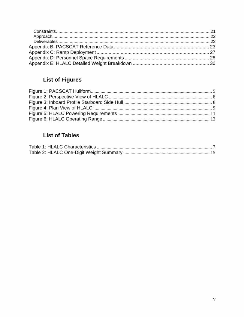
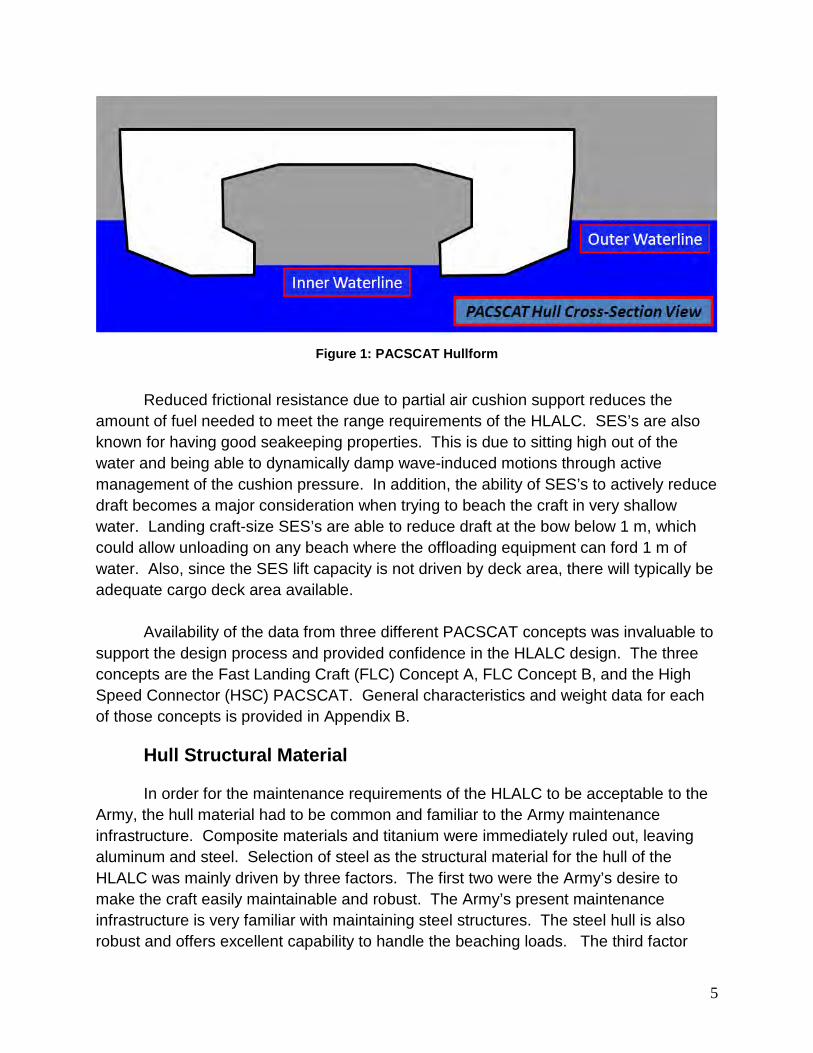
The PACSCAT hullform differs from other types of SES, in that it relies upon hull buoyancy to support a large fraction (35-50%) of the weight. This hullform provided the desired attributes of the T-Craft without the complexity of the ACV mode. Figure 1 shows the unique PACSCAT hullform.
5
Figure 1: PACSCAT Hullform
Reduced frictional resistance due to partial air cushion support reduces the
amount of fuel needed to meet the range requirements of the HLALC. SES’s are also known for having good seakeeping properties. This is due to sitting high out of the water and being able to dynamically damp wave-induced motions through active management of the cushion pressure. In addition, the ability of SES’s to actively reduce draft becomes a major consideration when trying to beach the craft in very shallow water. Landing craft-size SES’s are able to reduce draft at the bow below 1 m, which could allow unloading on any beach where the offloading equipment can ford 1 m of water. Also, since the SES lift capacity is not driven by deck area, there will typically be adequate cargo deck area available.
Availability of the data from three different PACSCAT concepts was invaluable to
support the design process and provided confidence in the HLALC design. The three concepts are the Fast Landing Craft (FLC) Concept A, FLC Concept B, and the High Speed Connector (HSC) PACSCAT. General characteristics and weight data for each of those concepts is provided in Appendix B.
Hull Structural Material
In order for the maintenance requirements of the HLALC to be acceptable to the Army, the hull material had to be common and familiar to the Army maintenance infrastructure. Composite materials and titanium were immediately ruled out, leaving aluminum and steel. Selection of steel as the structural material for the hull of the HLALC was mainly driven by three factors. The first two were the Army’s desire to make the craft easily maintainable and robust. The Army’s present maintenance infrastructure is very familiar with maintaining steel structures. The steel hull is also robust and offers excellent capability to handle the beaching loads. The third factor
6
was the selection of the PACSCAT hullform, which mitigates the increase in propulsion power resulting from the additional weight of a steel hull. As a result, the weight penalty does not affect the engine sizing or fuel load as much as it would in a high speed craft. The PACSCAT hulls are typically designed with sufficient buoyancy to support 35 to 50% of the craft full load displacement. This is a much higher buoyancy factor than is typical of an SES and, as a result, a PACSCAT has less powerful lift fans that consume less fuel. The fact that the HLALC is a medium speed craft (20-25 kts) also reduces the resistance penalty due to higher structural weight.
Hull Structural Evaluation
The HLALC structure was parametrically scaled from the three PACSCAT designs. The resulting HLALC structure was similar to if not heavier than the other PACSCAT designs. The cross deck structure that supports the vehicle deck and ties the two side hulls together is critical to the design. By linear scaling techniques, it was determined that the HLALC needed to have a minimum of 1.5 m cross-sectional height. Subsequently, it was determined that the spaces in the cross-deck structure could be used for functional purposes (stores, storage, service spaces, accommodations, etc) if the cross-sectional height were raised to 3 m. This cross-sectional height increase enabled a subsequent decision to house the one-piece ramp in a tunnel built in the cross-deck structure. By comparison, the 3 m new cross-deck structure exceeds the relationships established by the original PACSCAT HSC and FLC concepts. It also gives the HLALC a larger ratio of cross-sectional height to length (which is an indication of the craft’s ability to handle the transverse bending moment) and a larger ratio of cross-sectional height to beam (which gives some indication of the craft’s ability to handle the longitudinal bending moment). While the structural design needs to be developed further, it appears that the concept is achievable.
Propulsion
Gas turbines and diesel engines were considered for the HLALC. Though more expensive than diesel engines, gas turbines are small and would fit better because of the limited space in the hulls of an SES. However, diesel engines were selected because of the Army's preference for the diesel engine over gas turbines. In the current Army infrastructure, they generally do not teach the maintenance of gas turbines (other than for M1A1 tanks), so this technology would be less acceptable to them than diesel engines.
The HLALC propulsion power requirement is small enough to be met with
medium-speed diesel engines that fit into the side hulls of the craft. For consistency in
7
the type of fuel used on the craft, diesel engines were also selected to power the lift fans and electrical generators.
Concept Design
Principal Characteristics
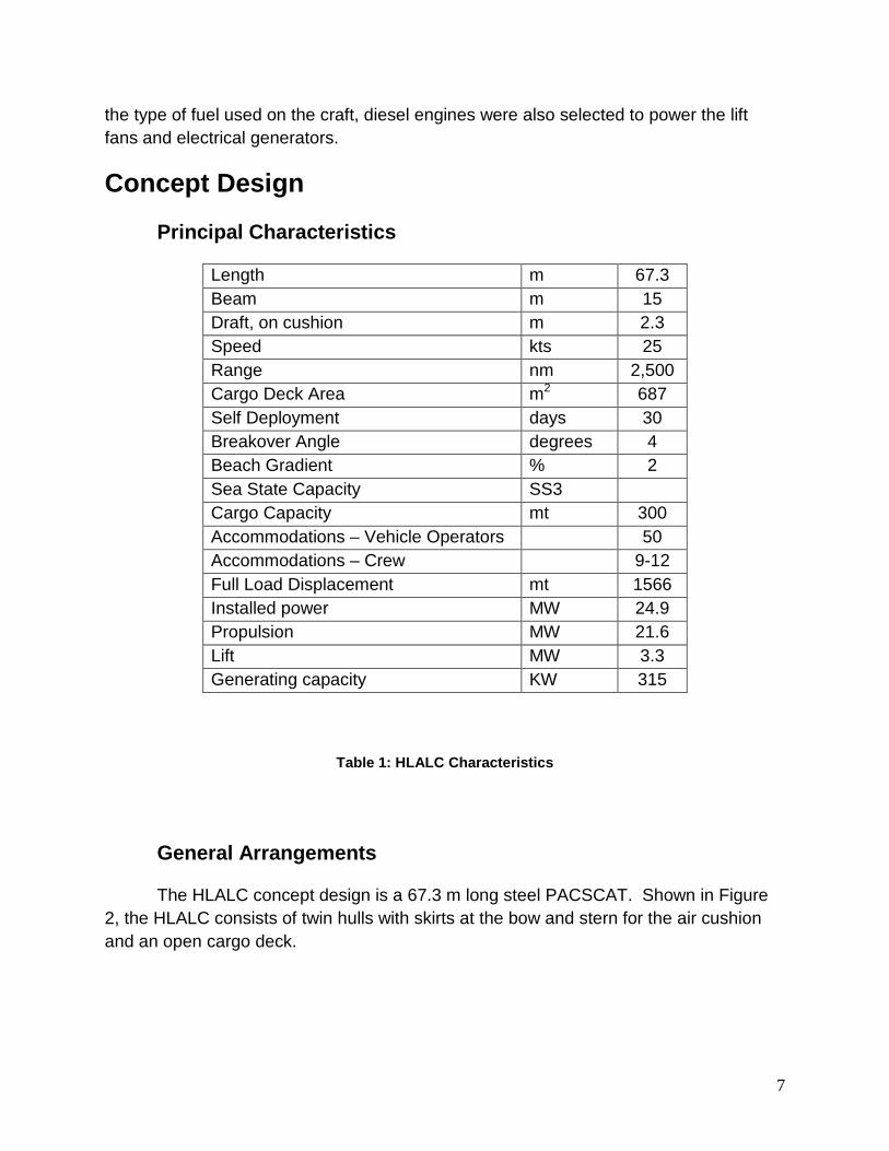
Length m 67.3 Beam m 15 Draft, on cushion m 2.3 Speed kts 25 Range nm 2,500 Cargo Deck Area m2 687 Self Deployment days 30 Breakover Angle degrees 4 Beach Gradient % 2 Sea State Capacity SS3 Cargo Capacity mt 300 Accommodations – Vehicle Operators 50 Accommodations – Crew 9-12 Full Load Displacement mt 1566 Installed power MW 24.9 Propulsion MW 21.6 Lift MW 3.3 Generating capacity KW 315
Table 1: HLALC Characteristics
General Arrangements
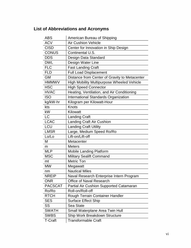
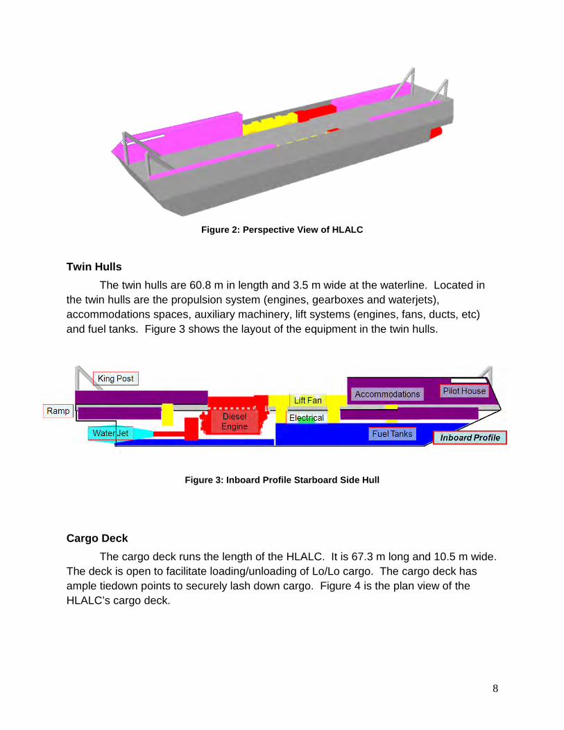
The HLALC concept design is a 67.3 m long steel PACSCAT. Shown in Figure 2, the HLALC consists of twin hulls with skirts at the bow and stern for the air cushion and an open cargo deck.
8
Figure 2: Perspective View of HLALC
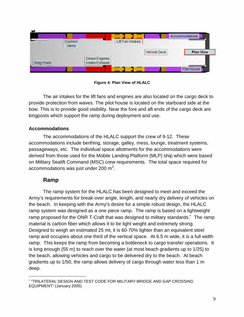
Twin Hulls
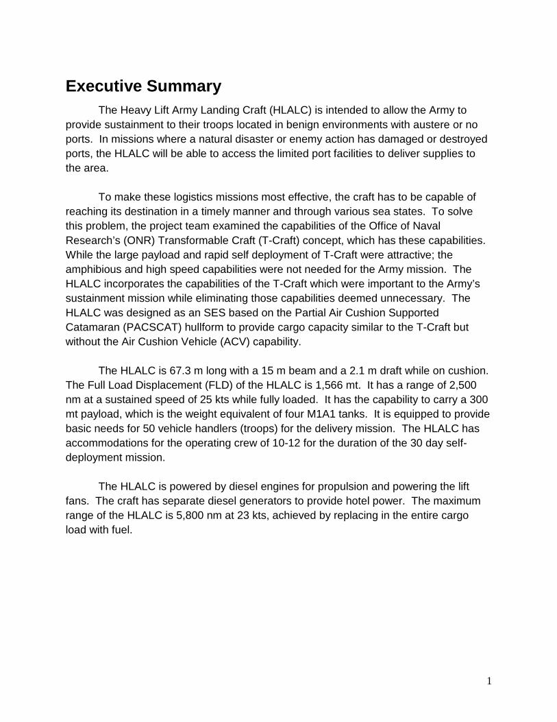
The twin hulls are 60.8 m in length and 3.5 m wide at the waterline. Located in the twin hulls are the propulsion system (engines, gearboxes and waterjets), accommodations spaces, auxiliary machinery, lift systems (engines, fans, ducts, etc) and fuel tanks. Figure 3 shows the layout of the equipment in the twin hulls.
Figure 3: Inboard Profile Starboard Side Hull
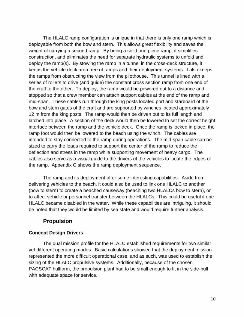
Cargo Deck
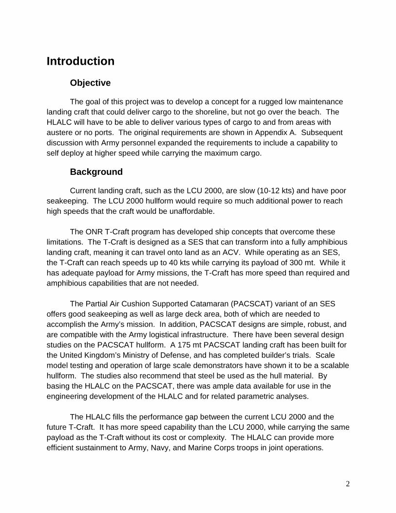
The cargo deck runs the length of the HLALC. It is 67.3 m long and 10.5 m wide. The deck is open to facilitate loading/unloading of Lo/Lo cargo. The cargo deck has ample tiedown points to securely lash down cargo. Figure 4 is the plan view of the HLALC’s cargo deck.
9
Figure 4: Plan View of HLALC
The air intakes for the lift fans and engines are also located on the cargo deck to
provide protection from waves. The pilot house is located on the starboard side at the bow. This is to provide good visibility. Near the fore and aft ends of the cargo deck are kingposts which support the ramp during deployment and use.
Accommodations
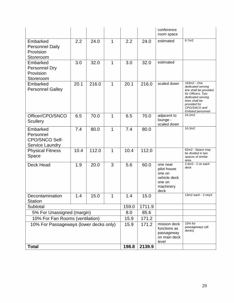
The accommodations of the HLALC support the crew of 9-12. These accommodations include berthing, storage, galley, mess, lounge, treatment systems, passageways, etc. The individual space allotments for the accommodations were derived from those used for the Mobile Landing Platform (MLP) ship which were based on Military Sealift Command (MSC) crew requirements. The total space required for accommodations was just under 200 m2.
Ramp
The ramp system for the HLALC has been designed to meet and exceed the Army’s requirements for break-over angle, length, and nearly dry delivery of vehicles on the beach. In keeping with the Army’s desire for a simple robust design, the HLALC ramp system was designed as a one piece ramp. The ramp is based on a lightweight ramp proposed for the ONR T-Craft that was designed to military standards.∗
∗ “TRILATERAL DESIGN AND TEST CODE FOR MILITARY BRIDGE AND GAP CROSSING EQUIPMENT” (January 2005)
The ramp material is carbon fiber which allows it to be light weight and extremely strong. Designed to weigh an estimated 25 mt, it is 60-70% lighter than an equivalent steel ramp and occupies about one third of the vertical space. At 6.5 m wide, it is a full width ramp. This keeps the ramp from becoming a bottleneck to cargo transfer operations. It is long enough (55 m) to reach over the water (at most beach gradients up to 1/25) to the beach, allowing vehicles and cargo to be delivered dry to the beach. At beach gradients up to 1/50, the ramp allows delivery of cargo through water less than 1 m deep.
10
The HLALC ramp configuration is unique in that there is only one ramp which is
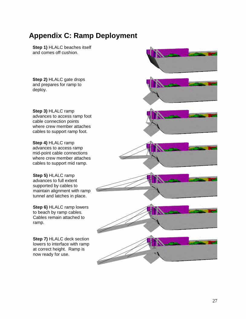
deployable from both the bow and stern. This allows great flexibility and saves the weight of carrying a second ramp. By being a solid one piece ramp, it simplifies construction, and eliminates the need for separate hydraulic systems to unfold and deploy the ramp(s). By stowing the ramp in a tunnel in the cross-deck structure, it keeps the vehicle deck area free of ramps and their deployment systems. It also keeps the ramps from obstructing the view from the pilothouse. This tunnel is lined with a series of rollers to drive (and guide) the constant cross section ramp from one end of the craft to the other. To deploy, the ramp would be powered out to a distance and stopped so that a crew member can attach support cables at the end of the ramp and mid-span. These cables run through the king posts located port and starboard of the bow and stern gates of the craft and are supported by winches located approximately 12 m from the king posts. The ramp would then be driven out to its full length and latched into place. A section of the deck would then be lowered to set the correct height interface between the ramp and the vehicle deck. Once the ramp is locked in place, the ramp foot would then be lowered to the beach using the winch. The cables are intended to stay connected to the ramp during operations. The mid-span cable can be sized to carry the loads required to support the center of the ramp to reduce the deflection and stress in the ramp while supporting movement of heavy cargo. The cables also serve as a visual guide to the drivers of the vehicles to locate the edges of the ramp. Appendix C shows the ramp deployment sequence.
The ramp and its deployment offer some interesting capabilities. Aside from delivering vehicles to the beach, it could also be used to link one HLALC to another (bow to stern) to create a beached causeway (beaching two HLALCs bow to stern), or to affect vehicle or personnel transfer between the HLALCs. This could be useful if one HLALC became disabled in the water. While these capabilities are intriguing, it should be noted that they would be limited by sea state and would require further analysis.
Propulsion
Concept Design Drivers
The dual mission profile for the HLALC established requirements for two similar yet different operating modes. Basic calculations showed that the deployment mission represented the more difficult operational case, and as such, was used to establish the sizing of the HLALC propulsive systems. Additionally, because of the chosen PACSCAT hullform, the propulsion plant had to be small enough to fit in the side-hull with adequate space for service.
11
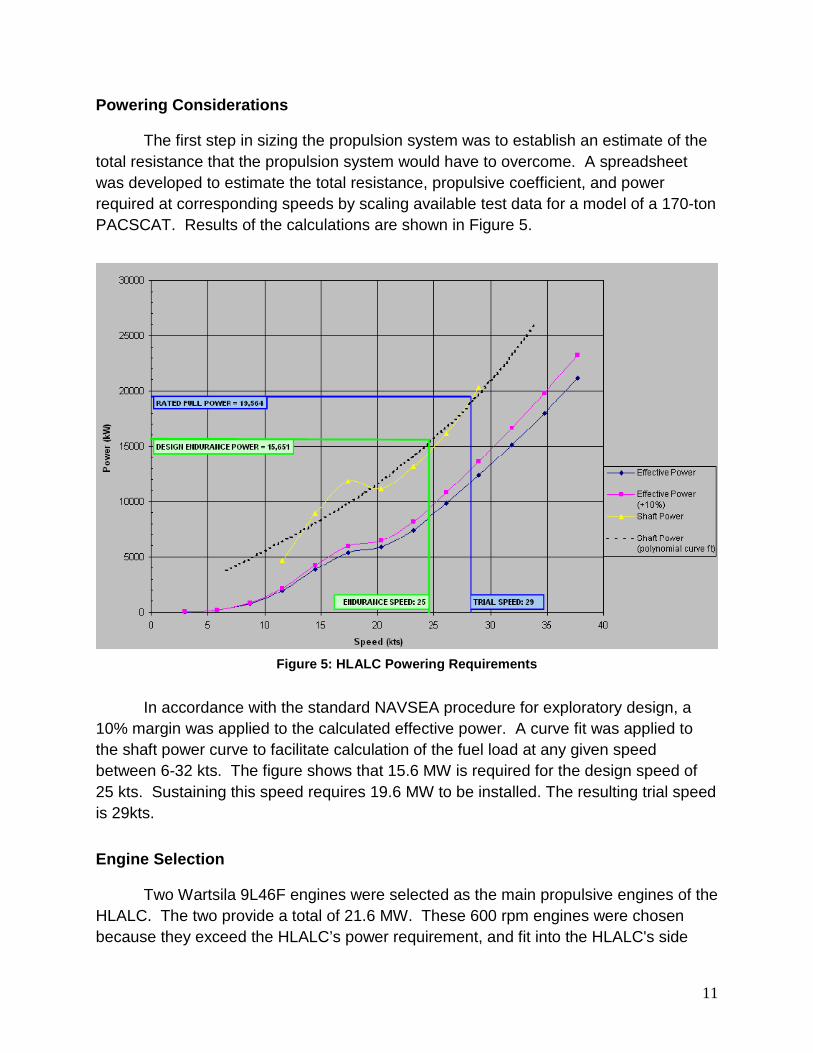
Powering Considerations
The first step in sizing the propulsion system was to establish an estimate of the total resistance that the propulsion system would have to overcome. A spreadsheet was developed to estimate the total resistance, propulsive coefficient, and power required at corresponding speeds by scaling available test data for a model of a 170-ton PACSCAT. Results of the calculations are shown in Figure 5.
Figure 5: HLALC Powering Requirements
In accordance with the standard NAVSEA procedure for exploratory design, a
10% margin was applied to the calculated effective power. A curve fit was applied to the shaft power curve to facilitate calculation of the fuel load at any given speed between 6-32 kts. The figure shows that 15.6 MW is required for the design speed of 25 kts. Sustaining this speed requires 19.6 MW to be installed. The resulting trial speed is 29kts.
Engine Selection
Two Wartsila 9L46F engines were selected as the main propulsive engines of the HLALC. The two provide a total of 21.6 MW. These 600 rpm engines were chosen because they exceed the HLALC’s power requirement, and fit into the HLALC's side
12
hulls. It should also be noted that they have a specific fuel consumption of 0.171 kg/kW-hr, which is less than most of the other engines investigated.
Two Caterpillar 3516 diesels, providing a total power of 3.28 MW, were selected to power the four lift fans. Taking up 12.9 cubic meters, these 1800 rpm engines have a specific fuel consumption of 0.225 kg/kW-hr.
The propulsion engines and lift fan engines together give the HLALC a total
installed power of 24.9 MW.
Propulsor Selection
Waterjet propulsion system was chosen over propellers because they are more efficient at the speeds intended for the HLALC, they offer greater maneuverability, and they are less prone to damage during beaching operations. Two Lips LJ142E waterjets (2.4 m diameter) were chosen as the propulsion for the HLALC. They typically require less draft than other forms of propulsion, which also means that there is less chance for damage during beaching. Waterjets operate with high thrust at low speeds which is necessary when de-beaching. Waterjets operate at a higher RPM than propellers resulting in smaller reduction gears. In addition, they do not require a reversing gear.
Auxiliary systems
Lift Fan Selection
The sizing of the lift fans was based on scaling three existing PACSCAT concepts to accommodate the size of the HLALC. Needing a total flow rate of 1,012,541 m3/h, four Witt C Type PRZ medium-pressure centrifugal lift fans were chosen to lift the HLALC, with each fan providing 126,568 m3/h.
Generators
The HLALC will have one Caterpillar 3406C generator set as the main generator to provide electrical power for the craft. A Caterpillar C6.6 ACERT generator set is provided as an emergency back-up generator should the main generator fail. The size of the main generator was scaled from the three existing PACSCAT concepts, yielding a required power of 270 kW. The emergency generator was sized to be 40% of the main generator, or 108 kW. The total generated power is 428 kW, with 315 kW supplied by the main generator and 113 kW in the emergency generator.
13
Range and Fuel
Range for the HLALC deployment mission is 2,500 nm at 25 kts with the full 300 mt payload onboard. Therefore HLALC needs enough fuel to operate for 100 hours at 25 kts. While the 2,500 nm range is required in seaways through SS4, PACSCAT model test resistance data is only available through SS3 for a 170-ton PACSCAT hull form. As a result, HLALC seaway performance has been evaluated only through SS3.
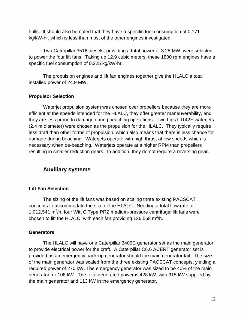
The required fuel load was calculated in accordance with DDS-200. It was estimated that 417 mt of fuel is needed to meet the HLALC’s deployment mission range requirement. Using this fuel load, a curve was plotted to show the ranges achievable at different speeds as shown in figure 6. The bottom curve of the lower band represents the range of the HLALC at a constant FLD with a full cargo load. However, SES’s do not have seawater ballast systems to burn-off fuel and maintain constant displacement. This means that it is more reasonable to estimate the HLALC range using the Breguet method of approximating the effect of reduction in displacement due to fuel burn-off. The upper curve in the bottom band yields a more realistic Breguet-based estimate of the potential range achievable by the HLALC.
Figure 6: HLALC Operating Range
14
There are three sets of curves on the HLALC operating range chart. The lower
bands of curves represent the variation in range baseline requirement of 2,500 nm, at 25 kts, with 300 mt payload. The figure shows that, regardless of payload, the HLALC has its greatest range when operated at a 23 kt speed. The HLALC has been designed with the fuel tank capacity to trade payload capacity for fuel load capacity to provide operational flexibility. This requires total fuel tank capacity for 717 mt of fuel. The second and third sets of curves show the ranges corresponding to the 150 mt payload, and in the unloaded condition respectively.
Figure 6 shows that the HLALC could self deploy fully loaded carrying 300 mt
payload and at a speed of 23 kts, and travel over 2,900 nm. Likewise, if it were required to travel up to 4,250 nm, it could achieve that range by reducing the payload to 150 mt and taking on the extra weight in fuel. By trading all the payload capacity for fuel, the HLALC is estimated to have a maximum range of nearly 5,800 nm. This offers a great deal of flexibility to rapidly deploy and deliver assets where and when needed.
It may also be concluded that the current HLALC concept is probably over-
designed in the areas of propulsion power and fuel load. During the next phase of design, the size of the propulsion system could probably be reduced to reduce ship size and cost. This potential reduction in the size of the propulsion system would have a cascading effect on many of the other ships systems.
Weight Estimation
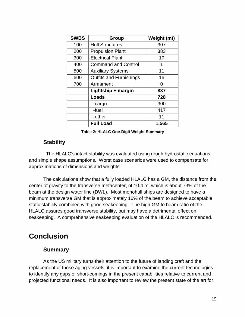
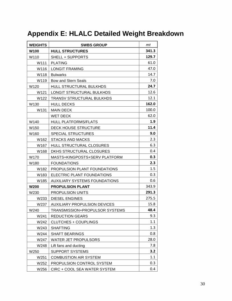
Lightship weight estimates for propulsion engines and waterjets were based on vendor data. The remaining lightship weights were parametrically scaled using data from the three PACSCAT designs. A 15% lightship weight margin was included. HLALC weights are summarized in Table 2. Weight estimate details are given in Appendix E.
15
SWBS Group Weight (mt)
100 Hull Structures 307 200 Propulsion Plant 383 300 Electrical Plant 10 400 Command and Control 1 500 Auxiliary Systems 11 600 Outfits and Furnishings 16 700 Armament 0
Lightship + margin 837 Loads 728 -cargo 300 -fuel 417 -other 11 Full Load 1,565
Table 2: HLALC One-Digit Weight Summary
Stability
The HLALC’s intact stability was evaluated using rough hydrostatic equations and simple shape assumptions. Worst case scenarios were used to compensate for approximations of dimensions and weights.
The calculations show that a fully loaded HLALC has a GM, the distance from the center of gravity to the transverse metacenter, of 10.4 m, which is about 73% of the beam at the design water line (DWL). Most monohull ships are designed to have a minimum transverse GM that is approximately 10% of the beam to achieve acceptable static stability combined with good seakeeping. The high GM to beam ratio of the HLALC assures good transverse stability, but may have a detrimental effect on seakeeping. A comprehensive seakeeping evaluation of the HLALC is recommended.
Conclusion
Summary
As the US military turns their attention to the future of landing craft and the replacement of those aging vessels, it is important to examine the current technologies to identify any gaps or short-comings in the present capabilities relative to current and projected functional needs. It is also important to review the present state of the art for
16
this type of craft. This project was the result of such an exercise. The Heavy Lift Army Landing Craft concept design utilizes the PACSCAT hull form, which is a variant of an SES. The HLALC concept design was developed to be a rugged, low maintenance landing craft that can deliver cargo to the shoreline at higher speeds with improved seakeeping. The HLALC concept is able to deliver various types of vehicles and cargo to and from beach areas as well as austere port facilities. It is also capable of long range self deployment. This will improve throughput for the sustainment mission.
Future Work
In future iterations of the HLALC concept evolution several issues should be further examined.
The effects of sea states upon the craft need to be studied, especially the effects of sea state on speed, stability, and cargo transfer. These effects need to be studied further to determine the operational limits of the HLALC and to assess its Joint Operations capabilities.
The weight estimate should be refined along with the center of gravity of the design, as the design progresses. A more detailed analysis of the hull structure should be made to ensure the structural adequacy and validate the weight estimate.
A more detailed structural analysis should be done on the ramp. The ramp deployment system also requires further development
What We Learned
The main purpose of the Naval Research Enterprise Intern Program (NREIP) is to develop naval engineers. This project successfully took a crew of mechanical engineers and taught them the basics of ship design.
The HLALC project team reviewed the design development work previously completed for the T-Craft project, particularly the new approaches that had been investigated. In addition, the mentors from the Center of Innovation in Ship Design (CISD) provided guidance from their valuable ship design experience to the group.
Lastly, we learned several principles of designing a ship concept from scratch. The first was to start working with reasonable assumptions based on past experience and similar vessels. This allowed the project to continually move forward and not get stuck at one phase. We also learned that the sooner the quantitative analysis begins the better the design can progress. Since design is an iterative process, more detailed

17
work will always come later and the initial assumptions will be confirmed or revised. A good example of this was the total ship size which we often changed due to better understanding of mission, new constraints from arrangements, changing margins, etc.
Overall this project was an excellent experience and will benefit each of the team members throughout their future careers. We wish to express our thanks at having been given the opportunity to work on this project, and we look forward to seeing what the future holds for the HLALC.
18
References 1. T-Craft Phase II Final Report. Textron. April 2010.
2. T-Craft Phase II Results and Phase III Plan Oral Presentation. Textron. May
2010.
3. ABS High Speed Naval Craft Rules. ABS. 2007.
4. Description of the PACSCAT High Speed Connector Ship. IMMA Ltd. Dec 2004 [Commercial in Confidence]
5. J.C. Lewthwaite & C Wagner. A German Littoral Combat Ship Based on the
PACSCAT Concept.
6. John C Lewthwaite. The PACSCAT High-Speed Connector Ship.
7. A Review of the PACSCAT in the MPF (F) Lighterage Role. IMMA Ltd. July 2003. [Commercial in Confidence]
8. John C Lewthwaite. Update on PACSCAT Technology. Multi-Agency Craft
Conference.
9. T-Craft Phase II QPR #5. Textron. Nov 2009.
10. IMAA develops LCS version of PACSCAT for German Navy. Warship Technology. July/August 2004 pg 14.
11. Sverre Steen. Experiences with Seakeeping Capabilities of SES Ships. Oct
2004.
12. Revised Operation Requirements Document for the Theater Support Vessel (TSV) ACAT II. Sept 2004.
13. Technical/Capability Demonstrator for a Fast Landing Craft. DSTL. March 2008.
14. R.A. Wilson, S.M. Wells, and C.E. Heber. Powering Prediction for Surface Effect
Ships Based on Model Results. July 1978. [Unclassified]
15. .Wartsila 46F Engine Technology. Wartsila. 2007.

19
16. Work Boats. Reintjes. Feb 2006.
17. Centrifugal Fans. Witt and Sohn. Dec 2000
20
Appendix A: Initial Brief
Introduction
1. The US Army, Navy and Marine Corp operate a range of smaller vessels which can be broadly described as Landing Craft (LC) designed for moving vehicles and cargo from ship to shore. Each service has, however, a different set of specific operation requirements and desirable capabilities.
2. Recent Navy LC programs have been focused on supporting over the horizon seabasing concepts and have focused on improving the overall speed and load capacity of LC. There is also a continuing desire for LC to be able to project beyond the shoreline and insert troops and equipment inland and critically dry. This is reflected in the current use of Landing Craft Air Cushion (LCAC – hovercraft) and in recent projects such as the T-Craft project, which has looked at alternative ways of designing fast sea-going vessels that can also operate as fully amphibious air cushion vehicles ashore.
3. The T-craft lift capabilities, range and speed are believed to be attractive to the Army, however the craft systems to support over the beach air cushioned operations are not necessary to meet the army’s operational objectives, and are likely to incur unnecessary complexity and critical cost.
4. This project shall develop a concept LC to meet the Army’s needs. It will be cognizant of the T-Craft program and some of the other future Landing Craft designs and concepts around the world in order to generate a viable design for the Army.
Aim
5. Develop a baseline requirements set for a future Army LC – agree these with Army Sponsor;
6. Develop a viable concept design for a rugged, low maintenance landing craft to meet these requirements;
7. Assess the concept against navy and marine requirement sets to assess its ‘joint service’ utility.
21
Ship Design Requirements
8. Proposed design must meet the following criteria:
a. Payload weight – 4 × M1A1 tanks (approximately 300 tonnes);
b. Payload deck area – 650 sq m equipped with suitable tie-down fittings and equipment;
c. Drive through cargo deck;
d. Maximum speed target of 25 knots with 250 nm range at maximum speed;
e. Sustained speed for maximum range of 14 knots; desired range 2,500 nm
f. Capable of delivering vehicles and troops dry to the beach and to austere ports;
g. Maneuverability suitable for beaching operations and working alongside at sea pontoons; ability to maintain slow speed loitering economically;
h. Must be self-deployable for 30 days;
i. Provide accommodations for 50 vehicle operators/troops during high speed operations;
j. Must support full range of Army combat and support land vehicles as well as palletized/containerized cargo.
Areas of Technology Exploration
9. The design team is likely to investigate the following areas:
a. Non-conventional hullforms;
b. Propulsion systems;
c. Ramps and rapidly deployable causeways;
d. Lightweight structures;
Constraints
10. The report and design shall be unclassified, including all supporting analysis and data amended as necessary.
22
Approach
11. The competing ideas shall be reduced to a preferred concept using a decision making process.
12. A system design synthesis model shall be developed. A complete system synthesis shall be undertaken. A balanced design shall result with a corresponding performance analysis.
13. The implications of any new technology or operational issues shall be noted. Recommendation for follow on work shall be documented.
Deliverables
14. All work will be documented in a CISD Project Technical Report. The final report and presentation shall be suitable for unclassified, public release.
15. During the first 2 weeks the team will produce a team project plan of actions, assignments and milestones to be presented to CISD leadership for approval. During the project this plan shall be maintained.
16. The team will develop and give informal intermediate presentations and a final project presentation.
17. The resulting design shall be detailed including a single sheet summary of characteristics including estimated performance, a comprehensive SWBS breakdown, an area/volume summary, and design drawings.
18. The team will be encouraged to produce a technical paper from the final report suitable for publishing at a professional society conference.
23
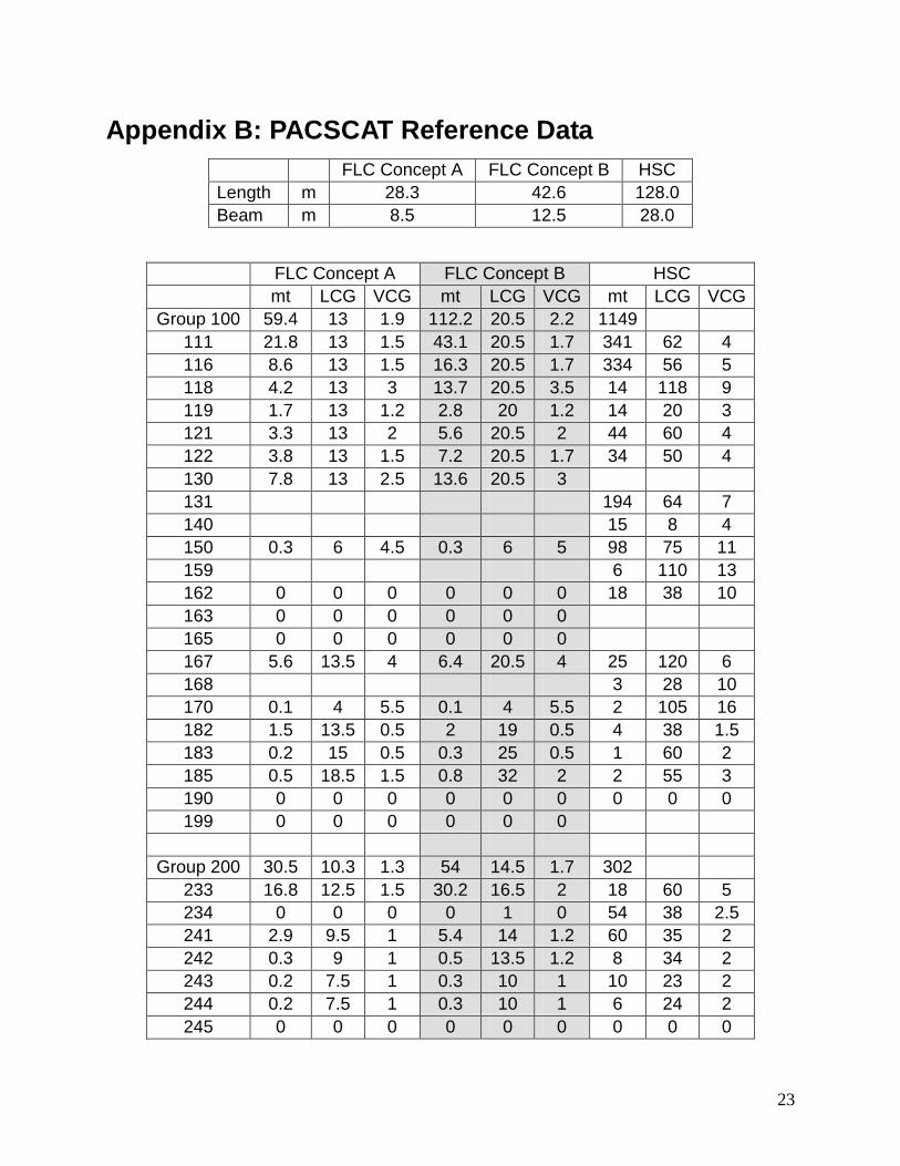
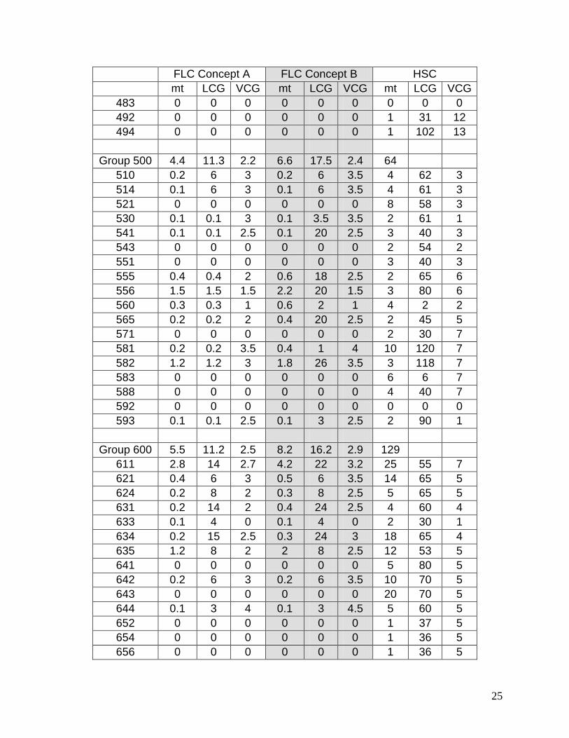
Appendix B: PACSCAT Reference Data FLC Concept A FLC Concept B HSC Length m 28.3 42.6 128.0 Beam m 8.5 12.5 28.0
FLC Concept A FLC Concept B HSC mt LCG VCG mt LCG VCG mt LCG VCG
Group 100 59.4 13 1.9 112.2 20.5 2.2 1149 111 21.8 13 1.5 43.1 20.5 1.7 341 62 4 116 8.6 13 1.5 16.3 20.5 1.7 334 56 5 118 4.2 13 3 13.7 20.5 3.5 14 118 9 119 1.7 13 1.2 2.8 20 1.2 14 20 3 121 3.3 13 2 5.6 20.5 2 44 60 4 122 3.8 13 1.5 7.2 20.5 1.7 34 50 4 130 7.8 13 2.5 13.6 20.5 3 131 194 64 7 140 15 8 4 150 0.3 6 4.5 0.3 6 5 98 75 11 159 6 110 13 162 0 0 0 0 0 0 18 38 10 163 0 0 0 0 0 0 165 0 0 0 0 0 0 167 5.6 13.5 4 6.4 20.5 4 25 120 6 168 3 28 10 170 0.1 4 5.5 0.1 4 5.5 2 105 16 182 1.5 13.5 0.5 2 19 0.5 4 38 1.5 183 0.2 15 0.5 0.3 25 0.5 1 60 2 185 0.5 18.5 1.5 0.8 32 2 2 55 3 190 0 0 0 0 0 0 0 0 0 199 0 0 0 0 0 0
Group 200 30.5 10.3 1.3 54 14.5 1.7 302
233 16.8 12.5 1.5 30.2 16.5 2 18 60 5 234 0 0 0 0 1 0 54 38 2.5 241 2.9 9.5 1 5.4 14 1.2 60 35 2 242 0.3 9 1 0.5 13.5 1.2 8 34 2 243 0.2 7.5 1 0.3 10 1 10 23 2 244 0.2 7.5 1 0.3 10 1 6 24 2 245 0 0 0 0 0 0 0 0 0
24
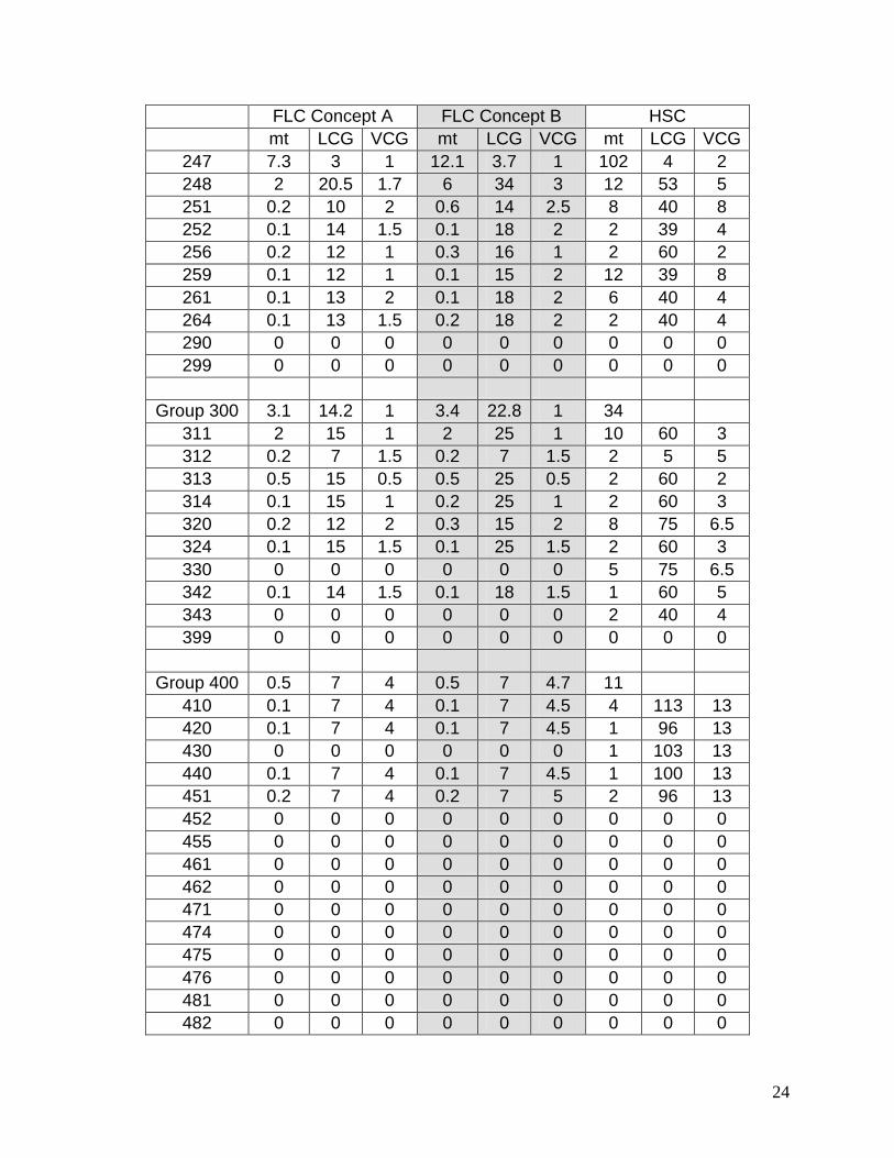
FLC Concept A FLC Concept B HSC mt LCG VCG mt LCG VCG mt LCG VCG
247 7.3 3 1 12.1 3.7 1 102 4 2 248 2 20.5 1.7 6 34 3 12 53 5 251 0.2 10 2 0.6 14 2.5 8 40 8 252 0.1 14 1.5 0.1 18 2 2 39 4 256 0.2 12 1 0.3 16 1 2 60 2 259 0.1 12 1 0.1 15 2 12 39 8 261 0.1 13 2 0.1 18 2 6 40 4 264 0.1 13 1.5 0.2 18 2 2 40 4 290 0 0 0 0 0 0 0 0 0 299 0 0 0 0 0 0 0 0 0
Group 300 3.1 14.2 1 3.4 22.8 1 34
311 2 15 1 2 25 1 10 60 3 312 0.2 7 1.5 0.2 7 1.5 2 5 5 313 0.5 15 0.5 0.5 25 0.5 2 60 2 314 0.1 15 1 0.2 25 1 2 60 3 320 0.2 12 2 0.3 15 2 8 75 6.5 324 0.1 15 1.5 0.1 25 1.5 2 60 3 330 0 0 0 0 0 0 5 75 6.5 342 0.1 14 1.5 0.1 18 1.5 1 60 5 343 0 0 0 0 0 0 2 40 4 399 0 0 0 0 0 0 0 0 0
Group 400 0.5 7 4 0.5 7 4.7 11
410 0.1 7 4 0.1 7 4.5 4 113 13 420 0.1 7 4 0.1 7 4.5 1 96 13 430 0 0 0 0 0 0 1 103 13 440 0.1 7 4 0.1 7 4.5 1 100 13 451 0.2 7 4 0.2 7 5 2 96 13 452 0 0 0 0 0 0 0 0 0 455 0 0 0 0 0 0 0 0 0 461 0 0 0 0 0 0 0 0 0 462 0 0 0 0 0 0 0 0 0 471 0 0 0 0 0 0 0 0 0 474 0 0 0 0 0 0 0 0 0 475 0 0 0 0 0 0 0 0 0 476 0 0 0 0 0 0 0 0 0 481 0 0 0 0 0 0 0 0 0 482 0 0 0 0 0 0 0 0 0
25
FLC Concept A FLC Concept B HSC mt LCG VCG mt LCG VCG mt LCG VCG
483 0 0 0 0 0 0 0 0 0 492 0 0 0 0 0 0 1 31 12 494 0 0 0 0 0 0 1 102 13
Group 500 4.4 11.3 2.2 6.6 17.5 2.4 64
510 0.2 6 3 0.2 6 3.5 4 62 3 514 0.1 6 3 0.1 6 3.5 4 61 3 521 0 0 0 0 0 0 8 58 3 530 0.1 0.1 3 0.1 3.5 3.5 2 61 1 541 0.1 0.1 2.5 0.1 20 2.5 3 40 3 543 0 0 0 0 0 0 2 54 2 551 0 0 0 0 0 0 3 40 3 555 0.4 0.4 2 0.6 18 2.5 2 65 6 556 1.5 1.5 1.5 2.2 20 1.5 3 80 6 560 0.3 0.3 1 0.6 2 1 4 2 2 565 0.2 0.2 2 0.4 20 2.5 2 45 5 571 0 0 0 0 0 0 2 30 7 581 0.2 0.2 3.5 0.4 1 4 10 120 7 582 1.2 1.2 3 1.8 26 3.5 3 118 7 583 0 0 0 0 0 0 6 6 7 588 0 0 0 0 0 0 4 40 7 592 0 0 0 0 0 0 0 0 0 593 0.1 0.1 2.5 0.1 3 2.5 2 90 1
Group 600 5.5 11.2 2.5 8.2 16.2 2.9 129
611 2.8 14 2.7 4.2 22 3.2 25 55 7 621 0.4 6 3 0.5 6 3.5 14 65 5 624 0.2 8 2 0.3 8 2.5 5 65 5 631 0.2 14 2 0.4 24 2.5 4 60 4 633 0.1 4 0 0.1 4 0 2 30 1 634 0.2 15 2.5 0.3 24 3 18 65 4 635 1.2 8 2 2 8 2.5 12 53 5 641 0 0 0 0 0 0 5 80 5 642 0.2 6 3 0.2 6 3.5 10 70 5 643 0 0 0 0 0 0 20 70 5 644 0.1 3 4 0.1 3 4.5 5 60 5 652 0 0 0 0 0 0 1 37 5 654 0 0 0 0 0 0 1 36 5 656 0 0 0 0 0 0 1 36 5
26
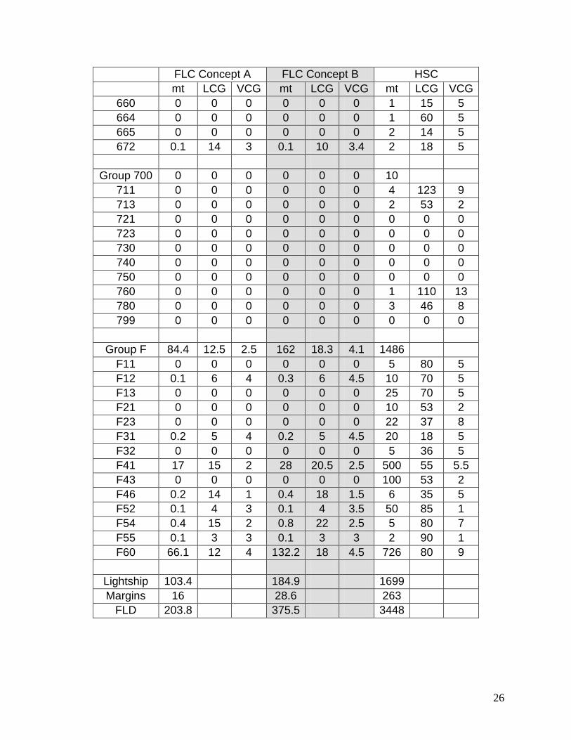
FLC Concept A FLC Concept B HSC mt LCG VCG mt LCG VCG mt LCG VCG
660 0 0 0 0 0 0 1 15 5 664 0 0 0 0 0 0 1 60 5 665 0 0 0 0 0 0 2 14 5 672 0.1 14 3 0.1 10 3.4 2 18 5
Group 700 0 0 0 0 0 0 10
711 0 0 0 0 0 0 4 123 9 713 0 0 0 0 0 0 2 53 2 721 0 0 0 0 0 0 0 0 0 723 0 0 0 0 0 0 0 0 0 730 0 0 0 0 0 0 0 0 0 740 0 0 0 0 0 0 0 0 0 750 0 0 0 0 0 0 0 0 0 760 0 0 0 0 0 0 1 110 13 780 0 0 0 0 0 0 3 46 8 799 0 0 0 0 0 0 0 0 0
Group F 84.4 12.5 2.5 162 18.3 4.1 1486
F11 0 0 0 0 0 0 5 80 5 F12 0.1 6 4 0.3 6 4.5 10 70 5 F13 0 0 0 0 0 0 25 70 5 F21 0 0 0 0 0 0 10 53 2 F23 0 0 0 0 0 0 22 37 8 F31 0.2 5 4 0.2 5 4.5 20 18 5 F32 0 0 0 0 0 0 5 36 5 F41 17 15 2 28 20.5 2.5 500 55 5.5 F43 0 0 0 0 0 0 100 53 2 F46 0.2 14 1 0.4 18 1.5 6 35 5 F52 0.1 4 3 0.1 4 3.5 50 85 1 F54 0.4 15 2 0.8 22 2.5 5 80 7 F55 0.1 3 3 0.1 3 3 2 90 1 F60 66.1 12 4 132.2 18 4.5 726 80 9
Lightship 103.4 184.9 1699 Margins 16 28.6 263
FLD 203.8 375.5 3448
27
Appendix C: Ramp Deployment
Step 1) HLALC beaches itself and comes off cushion.
Step 2) HLALC gate drops and prepares for ramp to deploy.
Step 3) HLALC ramp advances to access ramp foot cable connection points where crew member attaches cables to support ramp foot.
Step 4) HLALC ramp advances to access ramp mid-point cable connections where crew member attaches cables to support mid ramp.
Step 5) HLALC ramp advances to full extent supported by cables to maintain alignment with ramp tunnel and latches in place.
Step 6) HLALC ramp lowers to beach by ramp cables. Cables remain attached to ramp.
Step 7) HLALC deck section lowers to interface with ramp at correct height. Ramp is now ready for use.
28
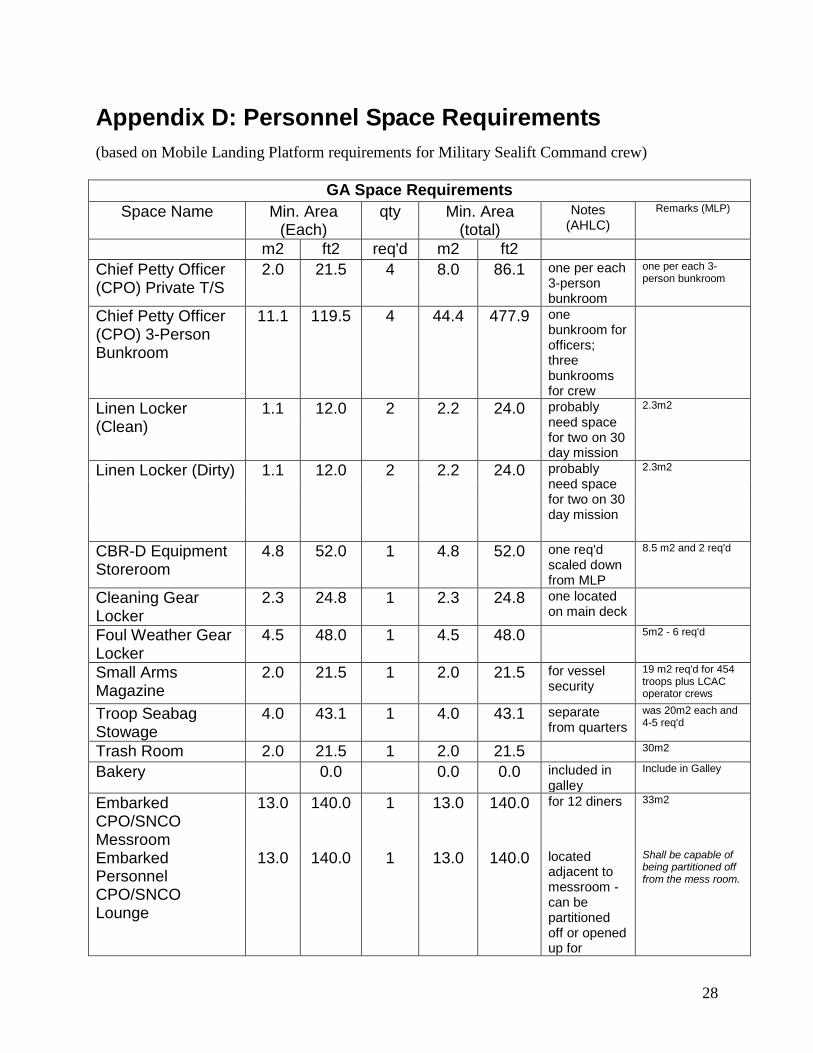
Appendix D: Personnel Space Requirements (based on Mobile Landing Platform requirements for Military Sealift Command crew)
GA Space Requirements Space Name Min. Area
(Each) qty Min. Area
(total) Notes
(AHLC) Remarks (MLP)
m2 ft2 req'd m2 ft2
Chief Petty Officer (CPO) Private T/S
2.0 21.5 4 8.0 86.1 one per each 3-person bunkroom
one per each 3-person bunkroom
Chief Petty Officer (CPO) 3-Person Bunkroom
11.1 119.5 4 44.4 477.9 one bunkroom for officers; three bunkrooms for crew
Linen Locker (Clean)
1.1 12.0 2 2.2 24.0 probably need space for two on 30 day mission
2.3m2
Linen Locker (Dirty) 1.1 12.0 2 2.2 24.0 probably need space for two on 30 day mission
2.3m2
CBR-D Equipment Storeroom
4.8 52.0 1 4.8 52.0 one req'd scaled down from MLP
8.5 m2 and 2 req'd
Cleaning Gear Locker
2.3 24.8 1 2.3 24.8 one located on main deck
Foul Weather Gear Locker
4.5 48.0 1 4.5 48.0 5m2 - 6 req'd
Small Arms Magazine
2.0 21.5 1 2.0 21.5 for vessel security
19 m2 req'd for 454 troops plus LCAC operator crews
Troop Seabag Stowage
4.0 43.1 1 4.0 43.1 separate from quarters
was 20m2 each and 4-5 req'd
Trash Room 2.0 21.5 1 2.0 21.5 30m2
Bakery 0.0 0.0 0.0 included in galley
Include in Galley
Embarked CPO/SNCO Messroom
13.0 140.0 1 13.0 140.0 for 12 diners 33m2
Embarked Personnel CPO/SNCO Lounge
13.0 140.0 1 13.0 140.0 located adjacent to messroom - can be partitioned off or opened up for
Shall be capable of being partitioned off from the mess room.
29
conference room space
Embarked Personnel Daily Provision Storeroom
2.2 24.0 1 2.2 24.0 estimated 6.7m2
Embarked Personnel Dry Provision Storeroom
3.0 32.0 1 3.0 32.0 estimated
Embarked Personnel Galley
20.1 216.0 1 20.1 216.0 scaled down 163m2 - One dedicated serving line shall be provided for Officers. Two dedicated serving lines shall be provided for CPO/SNCO and Enlisted personnel
Officer/CPO/SNCO Scullery
6.5 70.0 1 6.5 70.0 adjacent to lounge - scaled down
23.2m2
Embarked Personnel CPO/SNCO Self-Service Laundry
7.4 80.0 1 7.4 80.0 16.3m2
Physical Fitness Space
10.4 112.0 1 10.4 112.0 62m2 - Space may be divided in two spaces of similar area.
Deck Head 1.9 20.0 3 5.6 60.0 one near pilot house one on vehicle deck one on machinery deck
2.6m2 - 2 on each deck
Decontamination Station
1.4 15.0 1 1.4 15.0 13m2 each - 2 req'd
Subtotal 159.0 1711.9
5% For Unassigned (margin) 8.0 85.6
10% For Fan Rooms (ventilation) 15.9 171.2
10% For Passageways (lower decks only) 15.9 171.2 mission deck functions as passageway on main deck level
15% for passageways (all decks)
Total 198.8 2139.9
30
Appendix E: HLALC Detailed Weight Breakdown WEIGHTS SWBS GROUP mt
W100 HULL STRUCTURES 341.3
W110 SHELL + SUPPORTS 129.7
W111 PLATING 61.0
W116 LONGIT FRAMING 47.0
W118 Bulwarks 14.7
W119 Bow and Stern Seals 7.0
W120 HULL STRUCTURAL BULKHDS 24.7
W121 LONGIT STRUCTURAL BULKHDS 12.6
W122 TRANSV STRUCTURAL BULKHDS 12.1
W130 HULL DECKS 162.0
W131 MAIN DECK 100.0
WET DECK 62.0
W140 HULL PLATFORMS/FLATS 1.9
W150 DECK HOUSE STRUCTURE 11.4
W160 SPECIAL STRUCTURES 9.0
W162 STACKS AND MACKS 2.3
W167 HULL STRUCTURAL CLOSURES 6.3
W168 DKHS STRUCTURAL CLOSURES 0.4
W170 MASTS+KINGPOSTS+SERV PLATFORM 0.3
W180 FOUNDATIONS 2.3
W182 PROPULSION PLANT FOUNDATIONS 1.5
W183 ELECTRIC PLANT FOUNDATIONS 0.3
W185 AUXILIARY SYSTEMS FOUNDATIONS 0.6
W200 PROPULSION PLANT 343.9
W230 PROPULSION UNITS 291.3
W233 DIESEL ENGINES 275.5
W237 AUXILIARY PROPULSION DEVICES 15.8
W240 TRANSMISSION+PROPULSOR SYSTEMS 48.4
W241 REDUCTION GEARS 9.3
W242 CLUTCHES + COUPLINGS 1.1
W243 SHAFTING 1.3
W244 SHAFT BEARINGS 0.8
W247 WATER JET PROPULSORS 28.0
W248 Lift fans and ducting 7.8
W250 SUPPORT SYSTEMS 3.2
W251 COMBUSTION AIR SYSTEM 1.1
W252 PROPULSION CONTROL SYSTEM 0.3
W256 CIRC + COOL SEA WATER SYSTEM 0.4
31
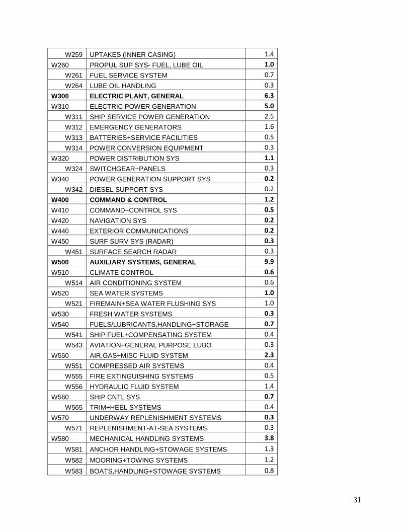
W259 UPTAKES (INNER CASING) 1.4
W260 PROPUL SUP SYS- FUEL, LUBE OIL 1.0
W261 FUEL SERVICE SYSTEM 0.7
W264 LUBE OIL HANDLING 0.3
W300 ELECTRIC PLANT, GENERAL 6.3
W310 ELECTRIC POWER GENERATION 5.0
W311 SHIP SERVICE POWER GENERATION 2.5
W312 EMERGENCY GENERATORS 1.6
W313 BATTERIES+SERVICE FACILITIES 0.5
W314 POWER CONVERSION EQUIPMENT 0.3
W320 POWER DISTRIBUTION SYS 1.1
W324 SWITCHGEAR+PANELS 0.3
W340 POWER GENERATION SUPPORT SYS 0.2
W342 DIESEL SUPPORT SYS 0.2
W400 COMMAND & CONTROL 1.2
W410 COMMAND+CONTROL SYS 0.5
W420 NAVIGATION SYS 0.2
W440 EXTERIOR COMMUNICATIONS 0.2
W450 SURF SURV SYS (RADAR) 0.3
W451 SURFACE SEARCH RADAR 0.3
W500 AUXILIARY SYSTEMS, GENERAL 9.9
W510 CLIMATE CONTROL 0.6
W514 AIR CONDITIONING SYSTEM 0.6
W520 SEA WATER SYSTEMS 1.0
W521 FIREMAIN+SEA WATER FLUSHING SYS 1.0
W530 FRESH WATER SYSTEMS 0.3
W540 FUELS/LUBRICANTS,HANDLING+STORAGE 0.7
W541 SHIP FUEL+COMPENSATING SYSTEM 0.4
W543 AVIATION+GENERAL PURPOSE LUBO 0.3
W550 AIR,GAS+MISC FLUID SYSTEM 2.3
W551 COMPRESSED AIR SYSTEMS 0.4
W555 FIRE EXTINGUISHING SYSTEMS 0.5
W556 HYDRAULIC FLUID SYSTEM 1.4
W560 SHIP CNTL SYS 0.7
W565 TRIM+HEEL SYSTEMS 0.4
W570 UNDERWAY REPLENISHMENT SYSTEMS 0.3
W571 REPLENISHMENT-AT-SEA SYSTEMS 0.3
W580 MECHANICAL HANDLING SYSTEMS 3.8
W581 ANCHOR HANDLING+STOWAGE SYSTEMS 1.3
W582 MOORING+TOWING SYSTEMS 1.2
W583 BOATS,HANDLING+STOWAGE SYSTEMS 0.8
32
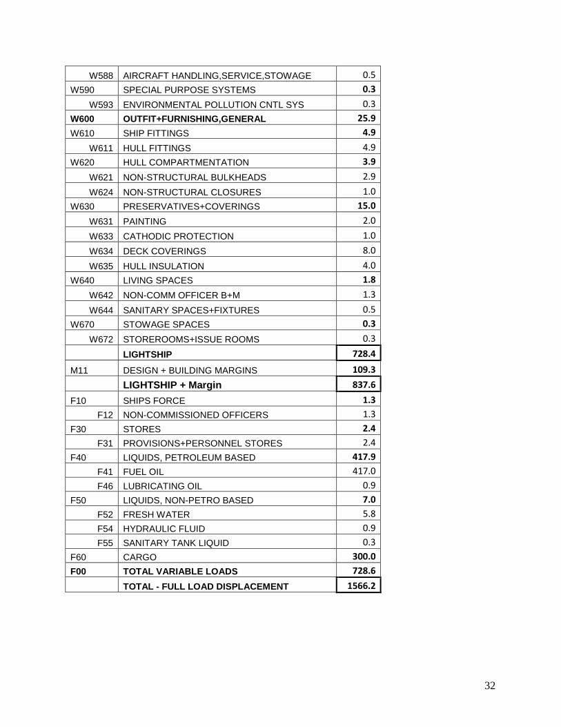
W588 AIRCRAFT HANDLING,SERVICE,STOWAGE 0.5
W590 SPECIAL PURPOSE SYSTEMS 0.3
W593 ENVIRONMENTAL POLLUTION CNTL SYS 0.3
W600 OUTFIT+FURNISHING,GENERAL 25.9
W610 SHIP FITTINGS 4.9
W611 HULL FITTINGS 4.9
W620 HULL COMPARTMENTATION 3.9
W621 NON-STRUCTURAL BULKHEADS 2.9
W624 NON-STRUCTURAL CLOSURES 1.0
W630 PRESERVATIVES+COVERINGS 15.0
W631 PAINTING 2.0
W633 CATHODIC PROTECTION 1.0
W634 DECK COVERINGS 8.0
W635 HULL INSULATION 4.0
W640 LIVING SPACES 1.8
W642 NON-COMM OFFICER B+M 1.3
W644 SANITARY SPACES+FIXTURES 0.5
W670 STOWAGE SPACES 0.3
W672 STOREROOMS+ISSUE ROOMS 0.3
LIGHTSHIP 728.4
M11 DESIGN + BUILDING MARGINS 109.3
LIGHTSHIP + Margin 837.6
F10 SHIPS FORCE 1.3
F12 NON-COMMISSIONED OFFICERS 1.3
F30 STORES 2.4
F31 PROVISIONS+PERSONNEL STORES 2.4
F40 LIQUIDS, PETROLEUM BASED 417.9
F41 FUEL OIL 417.0
F46 LUBRICATING OIL 0.9
F50 LIQUIDS, NON-PETRO BASED 7.0
F52 FRESH WATER 5.8
F54 HYDRAULIC FLUID 0.9
F55 SANITARY TANK LIQUID 0.3
F60 CARGO 300.0
F00 TOTAL VARIABLE LOADS 728.6
TOTAL - FULL LOAD DISPLACEMENT 1566.2