Embed Size (px)
Citation preview
G
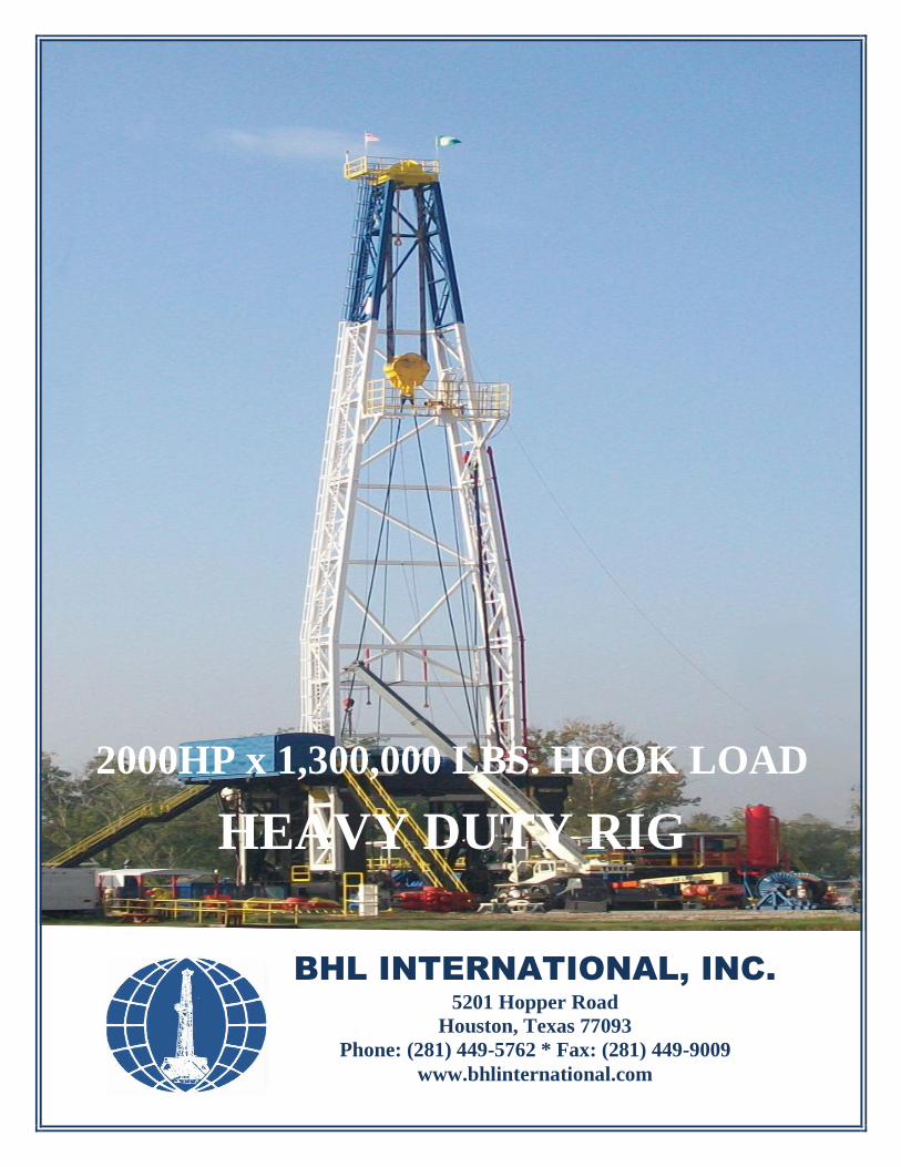
2000HP x 1,300,000 LBS. HOOK LOAD
HEAVY DUTY RIG
BHL INTERNATIONAL, INC.
5201 Hopper Road
Houston, Texas 77093
Phone: (281) 449-5762 * Fax: (281) 449-9009
www.bhlinternational.com
HEAVY DUTY LAND DRILLING RIG
2000 HP x 1,300,000 LBS. HOOK LOAD TECHNICAL PROPOSAL
Submitted By:
BHL INTERNATIONAL, INC. 5201 Hopper Rd.
Houston, Texas 77093
Phone: (281) 449-5762 * Fax: (281) 449-9009
www.bhlinternational.com
Page 2
TECHNICAL PRESENTATION February 27, 2014
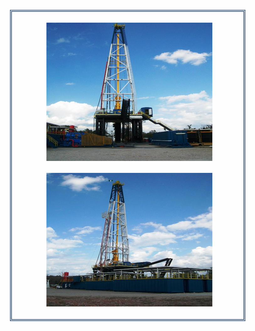
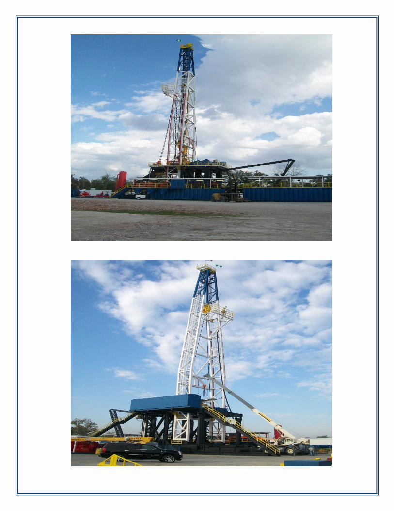
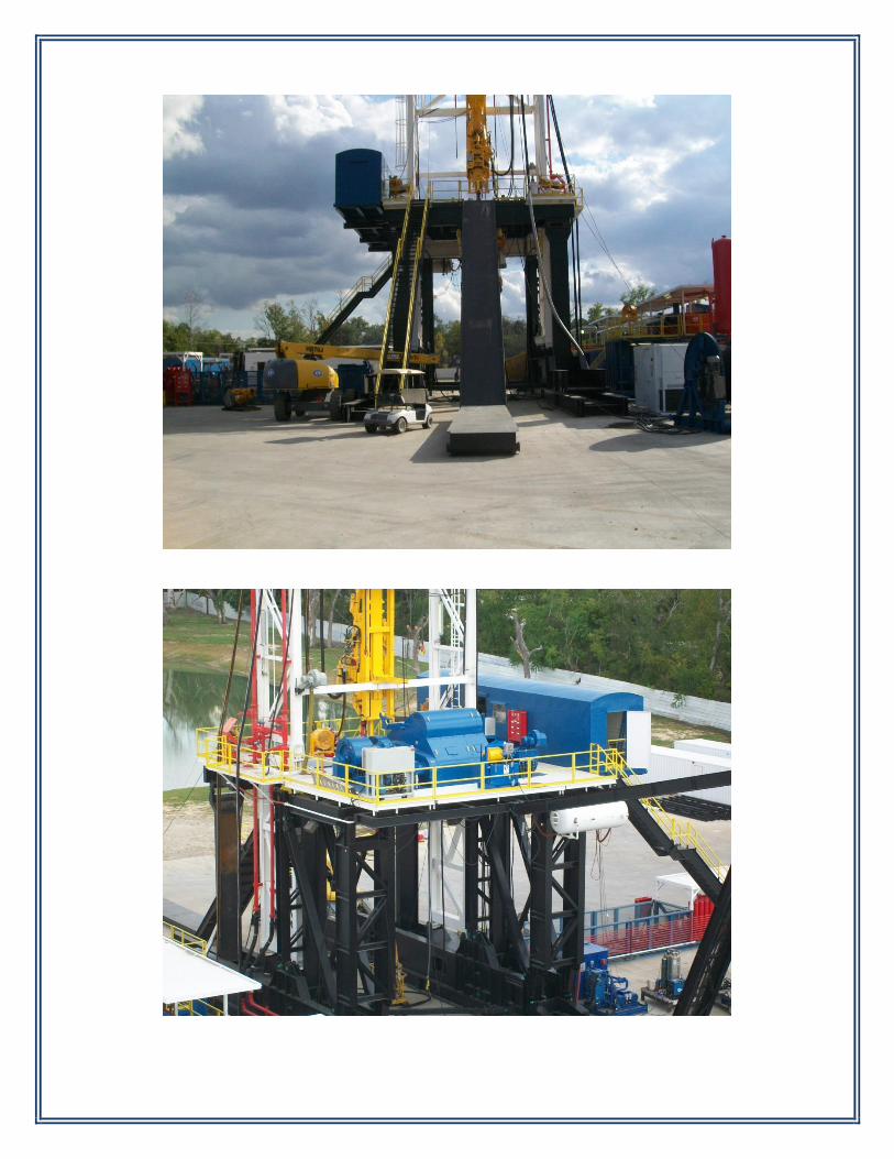
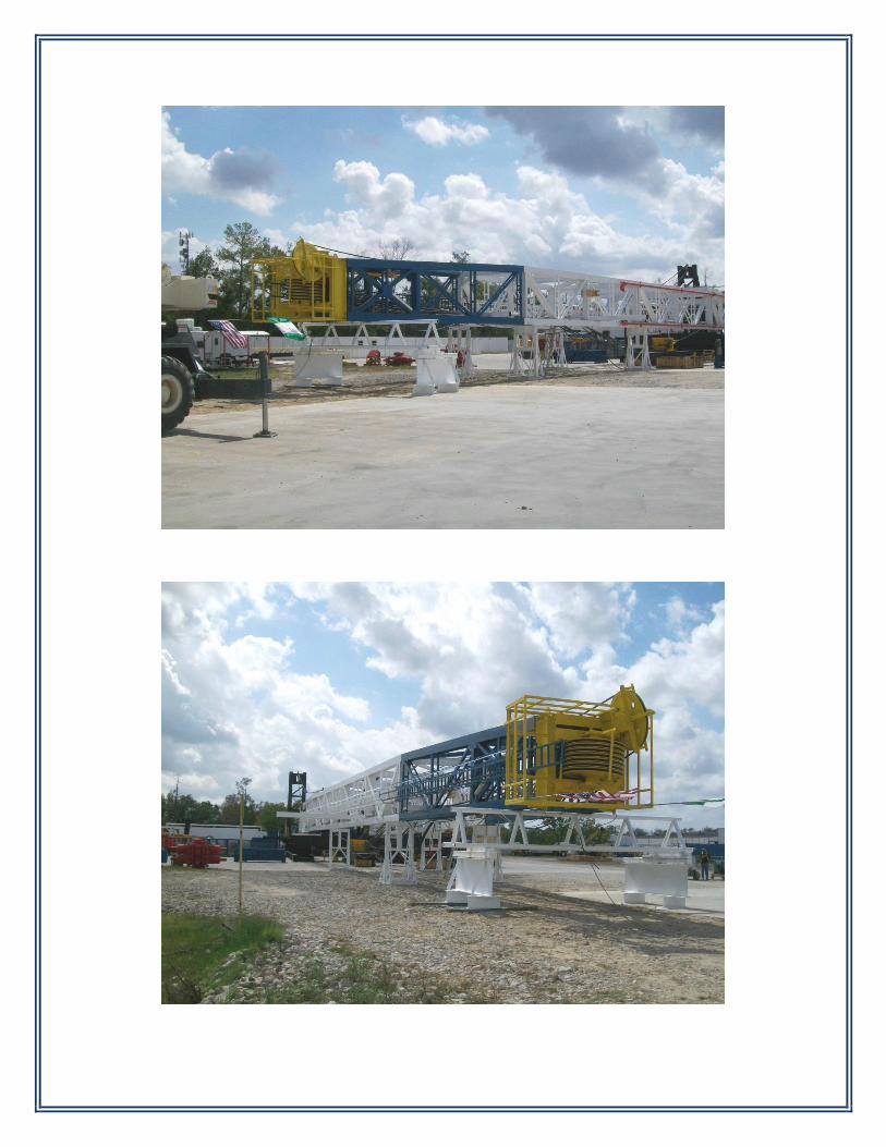
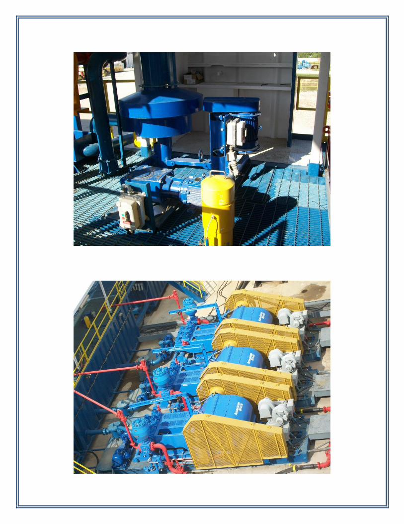
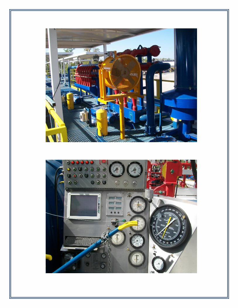
BHL International, Inc. (BHL) is pleased to submit this proposal for a Heavy Duty Land Drilling Rig. The Drilling Rig is capable of drilling, completion, testing, temporary abandonment and intervention work in connection with Land Drilling Rig operations. The maximum well depth is 20,000 ft. The Drilling Rig and its associated equipment where applicable, complies with recognized industry standards and relevant publications of the American Petroleum Institute (API), American Institute of Steel Construction (AISC), American Welding Society D1.1 (AWS D1.1), ISO 9001, ISO/TS 29001, International Association of Drilling Contractors (IADC), and ASME Boiler and Pressure Vessel Code. The Drilling Rig has a self-elevating mast and substructures. The mast raises to the vertical position together with the setback side of the substructures. The drawworks has a self-elevating substructure and is raised after the mast is up. The drawworks is located on the drill floor. The rotary table is independently driven and does not have to be connected to the drawworks. The brand new mast and substructure are designed and certified to API 4F latest Edition. This latest Edition has increased requirements for stability, overturning, sliding and higher wind loading that rigs built before 2008 do not have. To this date very few drilling structures have been built to this more stringent state of the art standards. RIG SKIDDING SYSTEM. The Rig Skidding System proposed is suited for projects where existing wellheads extend above ground level. The drilling rig is able to longitudinally skid off the ground on each side of the cellars and well heads. The Rig Skidding System is designed to take the full operating capacities of the rig during all drilling operations including all maximum combination wind loadings stipulated by API 4F. It shall be designed for erection loads, overturning and sliding as prescribed by API 4F. The equipment is furnished brand new. The rig skidding system is designed to skid the complete mast and substructure, fully assembled, complete with the drawworks, rotary table, top drive, traveling block, hook, all drill floor equipment and BOP stack. It shall be capable of skidding with full 600,00 lbs. of pipe setback. The entire assembly shall be able to skid together with the 11 ft. elevated pipe rack. MUD PUMPS. The three (3) mud pumps provided are all brand new with new fluid ends, new pulsation dampeners.
Page 3
THE DRAWWORKS is a newly refurbished 2000 HP, National 1320 UE Unit with new 7838 auxiliary brake, and all new bearings and clutches. THE SCR Unit is brand new with all new wiring and electrical cable distribution system for the entire rig. The SCR Unit is designed and engineered to provide the maximum degree of operational efficiency based on the power requirements of the rig. THE GENERATOR SETS are brand new Caterpillar 3512C's Tier III that are fuel efficient and environmentally emissions friendly. ALL INSTRUMENTATION EQUIPMENT are brand new. MUD PROCESSING EQUIPMENT equipment are new. AIR HOISTS & BOP HANDLING SYSTEM are brand new. The Drilling Rig is manufactured, rigged-up, tested, commissioned and packaged at BHL International, Inc. (BHL) Houston, Texas U.S.A. The rig components used are from established and reputable Oilfield Equipment Suppliers including National Oilwell Varco (NAT 1320 UE Drawworks), LeTourneau Technologies (500 Ton Top Drive), Forum AOI (Instrumentation and Automatic Driller), Caterpillar (CAT 3412C Engines), IEC (SCR Unit), Kemptron (Mud Processing Equipment and Centrifuges), Hydril (BOP's), Ingersol Rand (BOP Handling Systems and Air Hoists), etc. BHL is licensed, certified and registered under API 4F, API QI, ISO 9001 and ISO/TS 29001, ASME Boiler and Pressure Code; and the National Board of Boiler & Pressure Vessel Inspectors. BHL is a member of the American Petroleum Institute (API), International Associations of Drilling Contractors (IADC) and American Welding Society (AWS). BHL Personnel are members of the Society of Petroleum Engineers (SPE) and the American Association of Drilling Engineers (AADE). BHL's personnel are extensively experienced and current on drilling rig structures and equipment.
Page 4
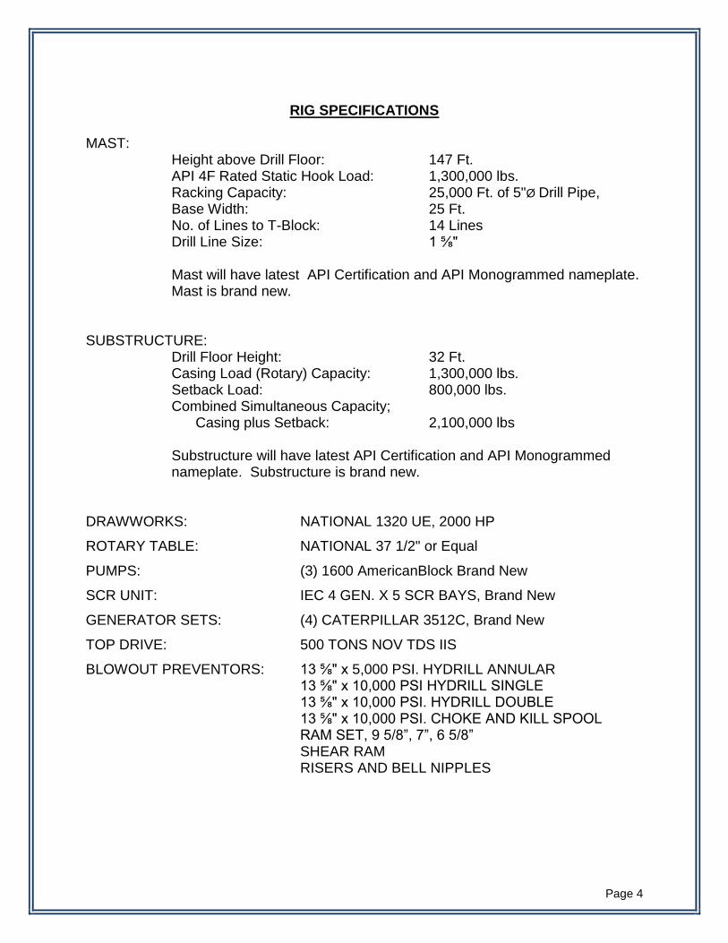
RIG SPECIFICATIONS
MAST: Height above Drill Floor: 147 Ft. API 4F Rated Static Hook Load: 1,300,000 lbs. Racking Capacity: 25,000 Ft. of 5"Ø Drill Pipe, Base Width: 25 Ft. No. of Lines to T-Block: 14 Lines Drill Line Size: 1 ⅝" Mast will have latest API Certification and API Monogrammed nameplate.
Mast is brand new. SUBSTRUCTURE: Drill Floor Height: 32 Ft. Casing Load (Rotary) Capacity: 1,300,000 lbs. Setback Load: 800,000 lbs. Combined Simultaneous Capacity; Casing plus Setback: 2,100,000 lbs Substructure will have latest API Certification and API Monogrammed
nameplate. Substructure is brand new. DRAWWORKS: NATIONAL 1320 UE, 2000 HP
ROTARY TABLE: NATIONAL 37 1/2" or Equal
PUMPS: (3) 1600 AmericanBlock Brand New
SCR UNIT: IEC 4 GEN. X 5 SCR BAYS, Brand New
GENERATOR SETS: (4) CATERPILLAR 3512C, Brand New
TOP DRIVE: 500 TONS NOV TDS IIS
BLOWOUT PREVENTORS: 13 ⅝" x 5,000 PSI. HYDRILL ANNULAR 13 ⅝" x 10,000 PSI HYDRILL SINGLE 13 ⅝" x 10,000 PSI. HYDRILL DOUBLE 13 ⅝" x 10,000 PSI. CHOKE AND KILL SPOOL RAM SET, 9 5/8”, 7”, 6 5/8” SHEAR RAM RISERS AND BELL NIPPLES
Page 5
LIQUID CAPACITIES:
ACTIVE MUD: 1500 BBLS
RESERVE MUD: 1500 BBLS
DRILL WATER 500 BBLS (80,000 Liters)
FUEL: 21,000 Gal. at rig site
Please refer to the detailed inventory for other equipment.
THE HEAVY DUTY LAND RIG PROPOSED COMPLIES WITH REQUIRED SPECIFICATIONS, SUPERIOR IN EFFICIENCY AND SAFETY THAN OTHER RIGS.
Page 6
BHL Ref. No. P-6184
February 27, 2014
PROPOSAL FOR:
MAST AND SUBSTRUCTURE 147ft. x 1,300,000 lbs. HOOK LOAD
API 4F-0167 MONOGRAMMED AND CERTIFIED
DRAWWORKS AT DRILL FLOOR LEVEL, SELF-ELEVATED AND
RAISED USING DRAWWORKS POWER (NO HYDRAULIC CYLINDERS REQUIRED)
BHL INTERNATIONAL, INC. 5223 Hopper Rd.
Houston, Texas 77093
Phone: (281) 449-5762 * Fax: (281) 449-9009
www.bhlinternational.com
Page 7
BHL Ref. No. P-5684H
BHL Ref. No. P-6184
February 27, 2014
PROPOSAL FOR MAST AND SUBSTRUCTURE
147FT. x 1,300,000 lbs. HOOK LOAD
ITEM QTY DESCRIPTION
A. 1 MAST Mast Assembly complete with 147’ clear height,
1,300,000 lbs. static hook load capacity, strung on 14 lines with 25’ base, ladders, lighting and crown assembly.
The setback substructure is also raised together with
the mast. The crown assembly is to be supplied complete with a
main cluster consisting of seven (7) sheaves, a fastline sheave each grooved for 1-5/8" wireline and arranged to accommodate a seven (7) sheave traveling block, handrails, bumper blocks, padeyes for block suspension line, tugger sheaves and top drive
The racking board is to be designed with a racking capacity of 20,000 of 5” drill pipe and ten (10) stands of 10” Drill Collars. The racking board shall be complete with an adjustable diving board, finger covers for the driller’s side fingers, a. pull back winch and mount, safety chains on each finger, 84” handrails,
BHL INTERNATIONAL, INC. 5201 Hopper Rd.
Houston, Texas 77093
Tel. (281) 449-5762 * Fax (281) 449-9009
www.bhlinternational.com
Page 8
ITEM QTY DESCRIPTION
racking board frame and a ladder landing platform with handrails.
Derrickman assist tugger at racking board to facilitate drill collars and drill pipe pull back.
Two (2) tong counterweights complete with buckets, guides, blocks and wirelines are to be included. Padeyes are to be mounted in the mast intermediate section.
Two (2) Tugger sheave units grooved for 9/16” diameter wireline.
Escape line, 9/16” x 1.5 x mast height with padeye and shackle.
The mast should contain all the necessary drive pins and bolts for assembly. Belly board, Mast stand.
SELF-ELEVATING SUBSTRUCTURE
The Self-Elevating type Substructure is to be supplied complete as per the following:
The substructure is rated for 1,300,000 lbs. casing load simultaneous with a setback of 800,000 lbs. (2,100,000 lbs. total capacity). The drill floor is 32' high from ground level.
The drawworks self-elevates to drill floor level using its own power. The setback elevates to drill floor level operating position together with the mast.
The structure is to be supplied with checkered floor plate, safety handrails with toe-boards.
BOP Trolley beams to extend to the front of the rig – under the V-door.
Features:
The Drill floor area is 32’ x 32’
Provision for independent rotary drive
Page 9
ITEM QTY DESCRIPTION
Three (3) sets of stairs from working floor, two (2) to the ground and one (1) to the trip tank landing complete with handrails.
One (1) Mousehole to be included for Range II pipe.
One (1) Rathole to be included for Range II pipe.
BOP stabilizer padeyes.
V door ramp with stairs.
Mast shoes.

Page 10
BHL Ref. No. P-6184 February 27, 2014
RIG SKIDDING SYSTEM
BHL INTERNATIONAL, INC.
5201 Hopper Rd.
Houston, Texas 77093
Phone: (281) 449-5762 * Fax: (281) 449-9009
www.bhlinternational.com
Page 11
BHL REF. NO. P-6184 February 27, 2014
RIG SKIDDING SYSTEM
BHL International, Inc. (BHL) is pleased to submit this proposal for a Drilling Rig Skidding System specified by the operator. The Client would like to use a land drilling rig for a project where existing wellheads extend 12 ft. above concrete pads and ground level. The drilling rig must be able to longitudinally skid off the concrete pads on each side of the cellars and well heads. The substructure, catwalk and pipe rack will have to clear wellheads up to 12 ft. requiring these structures to be elevated. BHL's mast and substructure design has a wide open area underneath the drill floor with no problem clearing the wellheads as specified. The skidding rails do not interfere with the existing wellheads. Rig Skidding System: The rig skidding system shall be designed to take the full operating capacities of the rig during all drilling operations including 1,300,000 lbs. hook load or casing load simultaneous with 800,000 lbs. full setback and all maximum combination wind loadings stipulated by API 4F. It shall be designed for erection loads, overturning and sliding as prescribed by API 4F. The rig skidding system is designed to skid the complete mast and substructure, fully assembled, complete with the drawworks, rotary table, top drive, traveling block, hook, all drill floor equipment and BOP stack. It shall be capable of skidding with 600,000 lbs. of pipe setback. The pipe rack maybe skidded with 600,000 lbs. of tubular but the setback will have to be empty (maximum 600,000 lbs. of pipe being moved but not 1,200,000 lbs. total). The rig shall be secured to the skid rails while drilling. Likewise with the elevated pipe rack. The substructure will have adequate guides while skidding. The guides will be capable of providing uplift stability in case of sudden wind gusts or other events that may produce overturning while skidding. The maximum allowable wind velocity while skidding is 30 MPH. Skidding shall stop and substructure clamped to the skid base for higher wind condition. The drilling rig and elevated pipe rack will skid longitudinally, drawworks side to pipe rack side or vice versa. Please refer to the drawings which further define our proposal.
Page 12
BHL SCOPE OF SUPPLY: A. One (1) Rig Skidding System as described in this proposal and the drawings. The Rig Skidding System is further described as follows:
The Skid Rail System requires 120 ft. of skid rails to set the substructure and elevated pipe rack for drilling operation plus space to set the hydraulic jacks and claw bases. The skid rails are 20 ft. long each section to allow for convenient "leap frogging" required for skidding. An extra 20 ft. leap frog section is needed to skid the rig forward or back, making the total length required along the concrete pad 140 ft. Seven (7) - 20 ft. leap frog sections on each of Driller's and Off-driller's side or a total of fourteen (14) - 20 ft. sections are required.
All sections are connected with double 100,000 psi high strength pins for fixity and continuity.
The top of the skid rails are slotted to anchor the jacking claw bases while skidding.
GUIDE BASES Guide Bases are included to guide and align the vertical extension and
elevated pipe rack on top of the skid rails. Each of the guide bases include a positive restraint to prevent uplift and overturning of the structures in the event of high wind and other events while skidding.
CLAMPS Clamps are provided to clamp and lock down the structures on the skid base
when not skidding.
SKIDDING JACKS Skidding jacks capable of skidding the rig are included in this proposal.
These jacks are push - pull types capable of pulling or pushing the rig.
CLAW BASES Claw Bases are provided to anchor the hydraulic jacks to the skid rail while
skidding.
CONTROL CONSOLE A portable console with its own stand is included for the skidding operation.
100 ft. long hoses are provided between the hydraulic jacks and the console. The existing Rig Hydraulic unit will be used and not included in this proposal.
Page 13
BHL RIG SKIDDING SYSTEM CAPABILITIES:
BHL personnel have designed extensive number of rig skidding systems for land, offshore and arctic rigs including over 40 offshore platform rig skidding systems. We worked on rig skidding for Union Platform Gilda (now Chevron Texaco) which has 96 well slots, the most number of wells on a platform. BHL is licensed, certified and registered under API Spec 4F, API Spec Q1, ISO 9001, TS 29001, ASME Boiler and Pressure Vessel Code; and The National Board of Boiler & Pressure Inspectors. Our certificates are attached.
Page 14
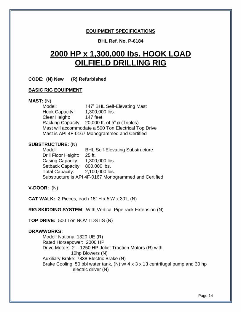
EQUIPMENT SPECIFICATIONS
BHL Ref. No. P-6184
2000 HP x 1,300,000 lbs. HOOK LOAD OILFIELD DRILLING RIG
CODE: (N) New (R) Refurbished BASIC RIG EQUIPMENT MAST: (N) Model: 147’ BHL Self-Elevating Mast Hook Capacity: 1,300,000 lbs. Clear Height: 147 feet Racking Capacity: 20,000 ft. of 5” ø (Triples) Mast will accommodate a 500 Ton Electrical Top Drive Mast is API 4F-0167 Monogrammed and Certified SUBSTRUCTURE: (N) Model: BHL Self-Elevating Substructure Drill Floor Height: 25 ft. Casing Capacity: 1,300,000 lbs. Setback Capacity: 800,000 lbs. Total Capacity: 2,100,000 lbs. Substructure is API 4F-0167 Monogrammed and Certified V-DOOR: (N) CAT WALK: 2 Pieces, each 18” H x 5’W x 30’L (N) RIG SKIDDING SYSTEM: With Vertical Pipe rack Extension (N) TOP DRIVE: 500 Ton NOV TDS IIS (N) DRAWWORKS: Model: National 1320 UE (R) Rated Horsepower: 2000 HP
Drive Motors: 2 – 1250 HP Joliet Traction Motors (R) with 10hp Blowers (N)
Auxiliary Brake: 7838 Electric Brake (N) Brake Cooling: 50 bbl water tank, (N) w/ 4 x 3 x 13 centrifugal pump and 30 hp
electric driver (N)
Page 15
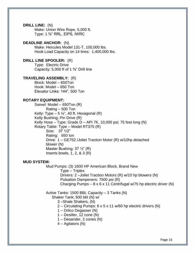
DRILL LINE: (N) Make: Union Wire Rope, 5,000 ft. Type: 1 ⅝” RRL, EIPS, IWRC DEADLINE ANCHOR: (N) Make: Hercules Model 131-T, 100,000 lbs. Hook Load Capacity on 14 lines: 1,400,000 lbs. DRILL LINE SPOOLER: (R) Type: Electric Drive Capacity: 5,000 ft of 1 ⅝” Drill line TRAVELING ASSEMBLY: (R) Block: Model – 650Ton Hook: Model – 650 Ton Elevator Links: 144”, 500 Ton ROTARY EQUIPMENT: Swivel: Model – 650Ton (R) Rating – 500 Ton Kelly: Type – 5 ¼", 40 ft. Hexagonal (R) Kelly Bushing; Pin Drive (R) Kelly Hose – Type: Grade D – API 7K, 10,000 psi; 75 feet long (N) Rotary Table: Type – Model RT375 (R) Size: 37 1/2” Rating: 650 ton Drive: 1 – GE752 /Joliet Traction Motor (R) w/10hp detached blower (N) Master Bushing: 37 ½” (R) Inserts bowls, 1, 2, & 3 (R) MUD SYSTEM: Mud Pumps: (3) 1600 HP American Block, Brand New Type – Triplex Drivers: 2 –Joliet Traction Motors (R) w/10 hp blowers (N) Pulsation Dampeners: 7500 psi (R) Charging Pumps – 8 x 6 x 11 Centrifugal w/75 hp electric driver (N) Active Tanks: 1500 BBL Capacity – 3 Tanks (N) Shaker Tank; 500 bbl (N) w/ 3 –Shale Shakers, (N) 2 – Circulating Pumps: 6 x 5 x 11 w/60 hp electric drivers (N) 1 – Drilco Degasser (N) 1 – Desilter, 12 cone (N) 1 – Desander, 2 cones (N) 4 – Agitators (N)
Page 16
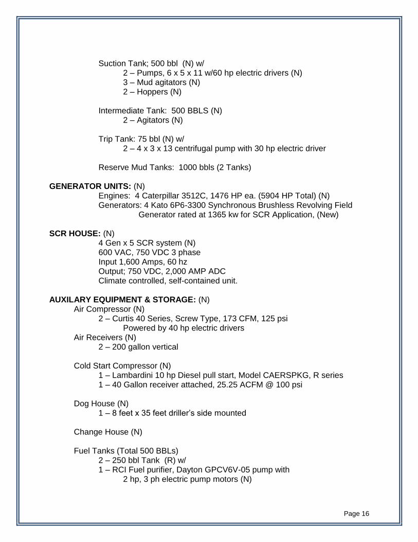
Suction Tank; 500 bbl (N) w/ 2 – Pumps, 6 x 5 x 11 w/60 hp electric drivers (N)
3 – Mud agitators (N) 2 – Hoppers (N) Intermediate Tank: 500 BBLS (N) 2 – Agitators (N) Trip Tank: 75 bbl (N) w/ 2 – 4 x 3 x 13 centrifugal pump with 30 hp electric driver Reserve Mud Tanks: 1000 bbls (2 Tanks)
GENERATOR UNITS: (N) Engines: 4 Caterpillar 3512C, 1476 HP ea. (5904 HP Total) (N) Generators: 4 Kato 6P6-3300 Synchronous Brushless Revolving Field
Generator rated at 1365 kw for SCR Application, (New) SCR HOUSE: (N)
4 Gen x 5 SCR system (N) 600 VAC, 750 VDC 3 phase Input 1,600 Amps, 60 hz Output; 750 VDC, 2,000 AMP ADC Climate controlled, self-contained unit. AUXILARY EQUIPMENT & STORAGE: (N) Air Compressor (N) 2 – Curtis 40 Series, Screw Type, 173 CFM, 125 psi
Powered by 40 hp electric drivers Air Receivers (N) 2 – 200 gallon vertical
Cold Start Compressor (N) 1 – Lambardini 10 hp Diesel pull start, Model CAERSPKG, R series
1 – 40 Gallon receiver attached, 25.25 ACFM @ 100 psi
Dog House (N) 1 – 8 feet x 35 feet driller’s side mounted
Change House (N)
Fuel Tanks (Total 500 BBLs) 2 – 250 bbl Tank (R) w/ 1 – RCI Fuel purifier, Dayton GPCV6V-05 pump with
2 hp, 3 ph electric pump motors (N)
Page 17
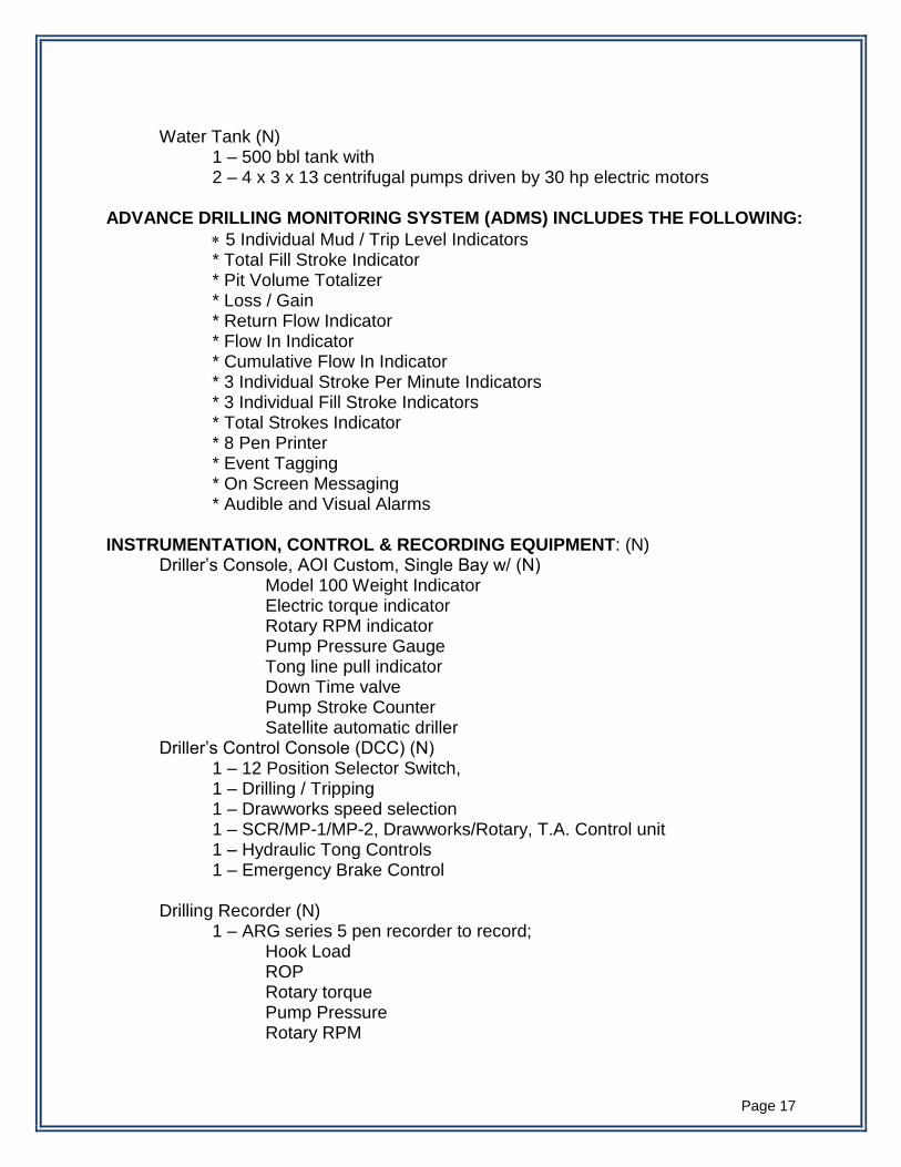
Water Tank (N)
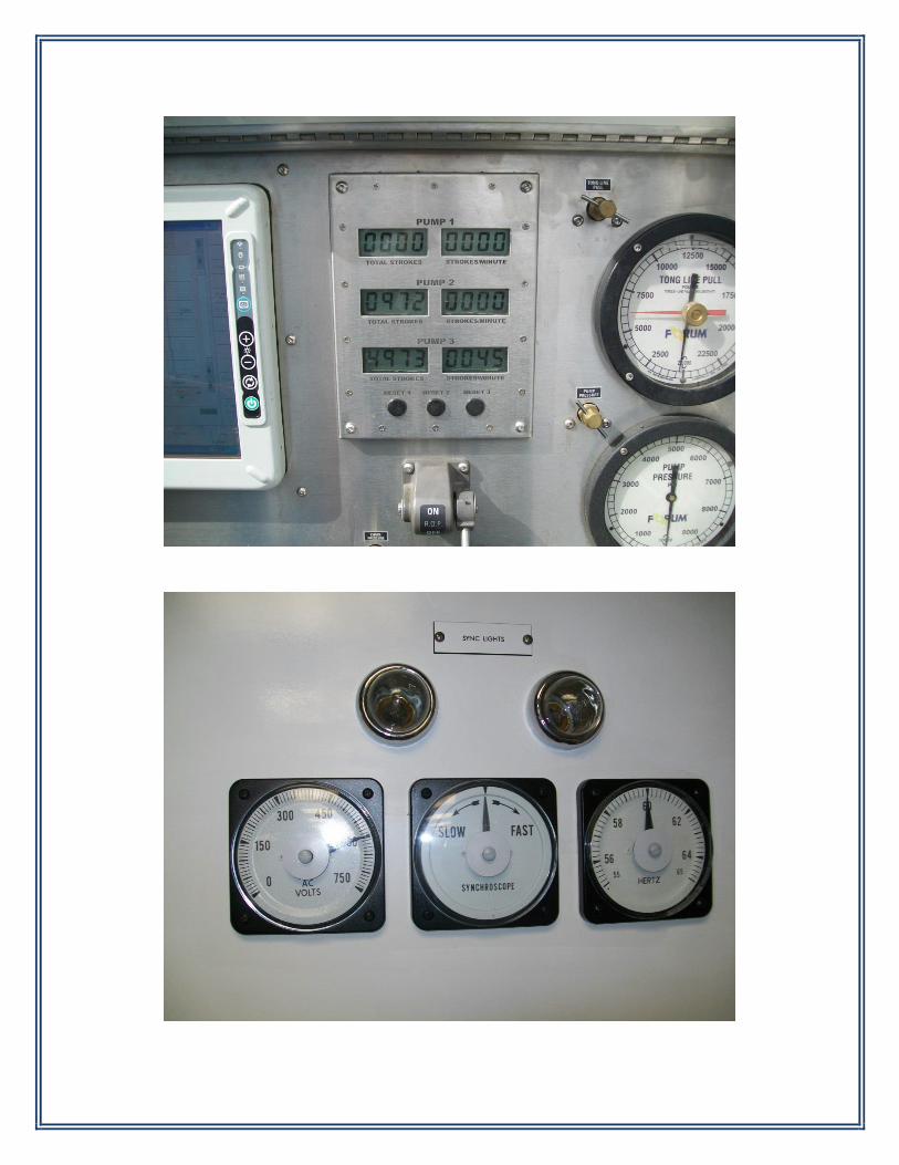
1 – 500 bbl tank with 2 – 4 x 3 x 13 centrifugal pumps driven by 30 hp electric motors ADVANCE DRILLING MONITORING SYSTEM (ADMS) INCLUDES THE FOLLOWING:
5 Individual Mud / Trip Level Indicators * Total Fill Stroke Indicator * Pit Volume Totalizer * Loss / Gain * Return Flow Indicator * Flow In Indicator * Cumulative Flow In Indicator * 3 Individual Stroke Per Minute Indicators * 3 Individual Fill Stroke Indicators * Total Strokes Indicator * 8 Pen Printer * Event Tagging * On Screen Messaging * Audible and Visual Alarms
INSTRUMENTATION, CONTROL & RECORDING EQUIPMENT: (N) Driller’s Console, AOI Custom, Single Bay w/ (N) Model 100 Weight Indicator Electric torque indicator Rotary RPM indicator Pump Pressure Gauge Tong line pull indicator Down Time valve Pump Stroke Counter Satellite automatic driller Driller’s Control Console (DCC) (N) 1 – 12 Position Selector Switch, 1 – Drilling / Tripping 1 – Drawworks speed selection 1 – SCR/MP-1/MP-2, Drawworks/Rotary, T.A. Control unit 1 – Hydraulic Tong Controls 1 – Emergency Brake Control
Drilling Recorder (N)
1 – ARG series 5 pen recorder to record; Hook Load ROP Rotary torque Pump Pressure Rotary RPM
Page 18
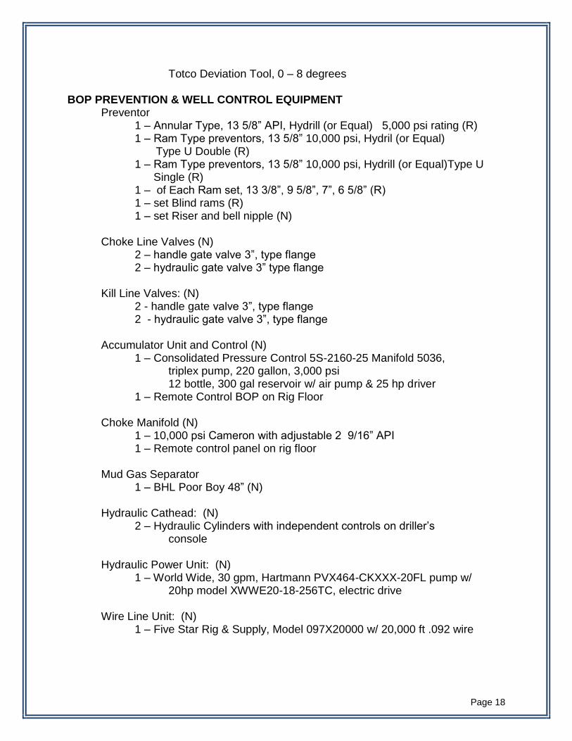
Totco Deviation Tool, 0 – 8 degrees BOP PREVENTION & WELL CONTROL EQUIPMENT Preventor 1 – Annular Type, 13 5/8” API, Hydrill (or Equal) 5,000 psi rating (R) 1 – Ram Type preventors, 13 5/8” 10,000 psi, Hydril (or Equal) Type U Double (R)
1 – Ram Type preventors, 13 5/8” 10,000 psi, Hydrill (or Equal)Type U Single (R)
1 – of Each Ram set, 13 3/8”, 9 5/8”, 7”, 6 5/8” (R) 1 – set Blind rams (R) 1 – set Riser and bell nipple (N) Choke Line Valves (N) 2 – handle gate valve 3”, type flange 2 – hydraulic gate valve 3” type flange Kill Line Valves: (N) 2 - handle gate valve 3”, type flange 2 - hydraulic gate valve 3”, type flange
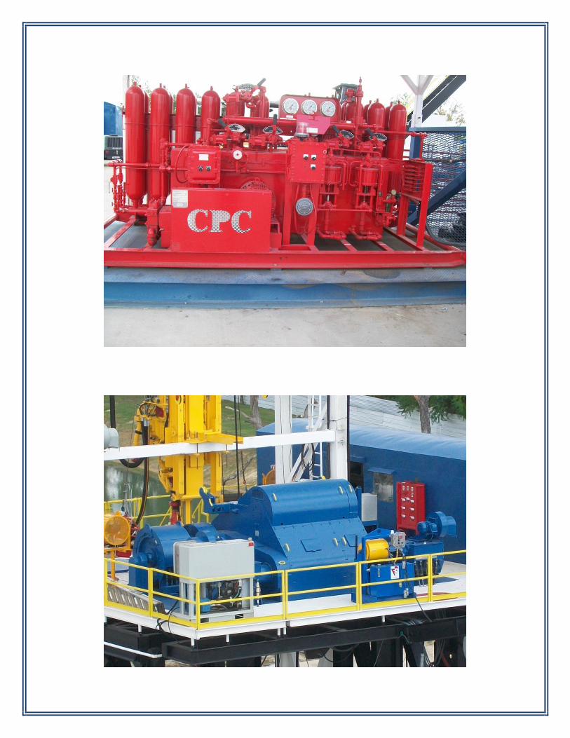
Accumulator Unit and Control (N) 1 – Consolidated Pressure Control 5S-2160-25 Manifold 5036, triplex pump, 220 gallon, 3,000 psi 12 bottle, 300 gal reservoir w/ air pump & 25 hp driver 1 – Remote Control BOP on Rig Floor
Choke Manifold (N) 1 – 10,000 psi Cameron with adjustable 2 9/16” API 1 – Remote control panel on rig floor
Mud Gas Separator 1 – BHL Poor Boy 48” (N)
Hydraulic Cathead: (N) 2 – Hydraulic Cylinders with independent controls on driller’s console
Hydraulic Power Unit: (N) 1 – World Wide, 30 gpm, Hartmann PVX464-CKXXX-20FL pump w/
20hp model XWWE20-18-256TC, electric drive
Wire Line Unit: (N) 1 – Five Star Rig & Supply, Model 097X20000 w/ 20,000 ft .092 wire

Page 19
Air Hoists: (N) 3 – Ingersoll Rand, Man Riding, for 5/8” line size
Tugger: 1 – Derrickman's Assist Tugger (N) at Racking Board
Kelly Spinner, Air drive, reversible (N)
Lift Assist Assembly, including Geronimo Seat and escape slide (N) Standpipe: (N) 5” Rated to 10,000 psi Standpipe Manifold: (N) Dual Stand Pipe Manifold rated to 10,000 psi. Rotary Hose: (N) 5” rated to 10,000 psi. BOP Handling System: (N)
40 Ton Capacity BOP Rails and Ingersol Rand (or Equal) Trolley and Hoist.
Headache Rack for Mast (R) ELECTRICAL DISTRIBUTION SYSTEM: (N)
All new cables, wirings, fittings, junction boxes, lighting, etc. for a complete drilling rig electrical distribution system in accordance and compliance with API specifications including API 500 Area and Hazardous Zone Classifications.
RIG PROCESS PIPING SYSTEM: (N)
All new process piping system including high pressure and low pressure mud systems, drill water, fuel, air, hydraulic, wash downs, drains and other piping required for a complete rig process piping system.
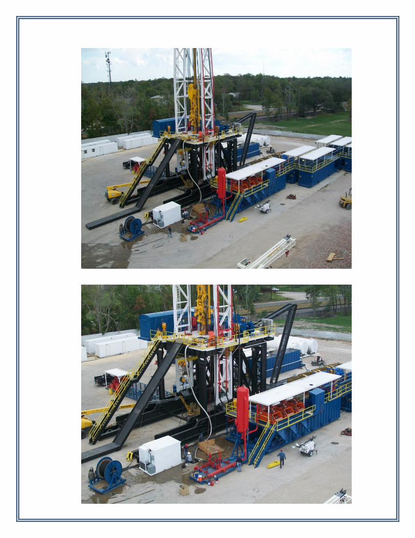
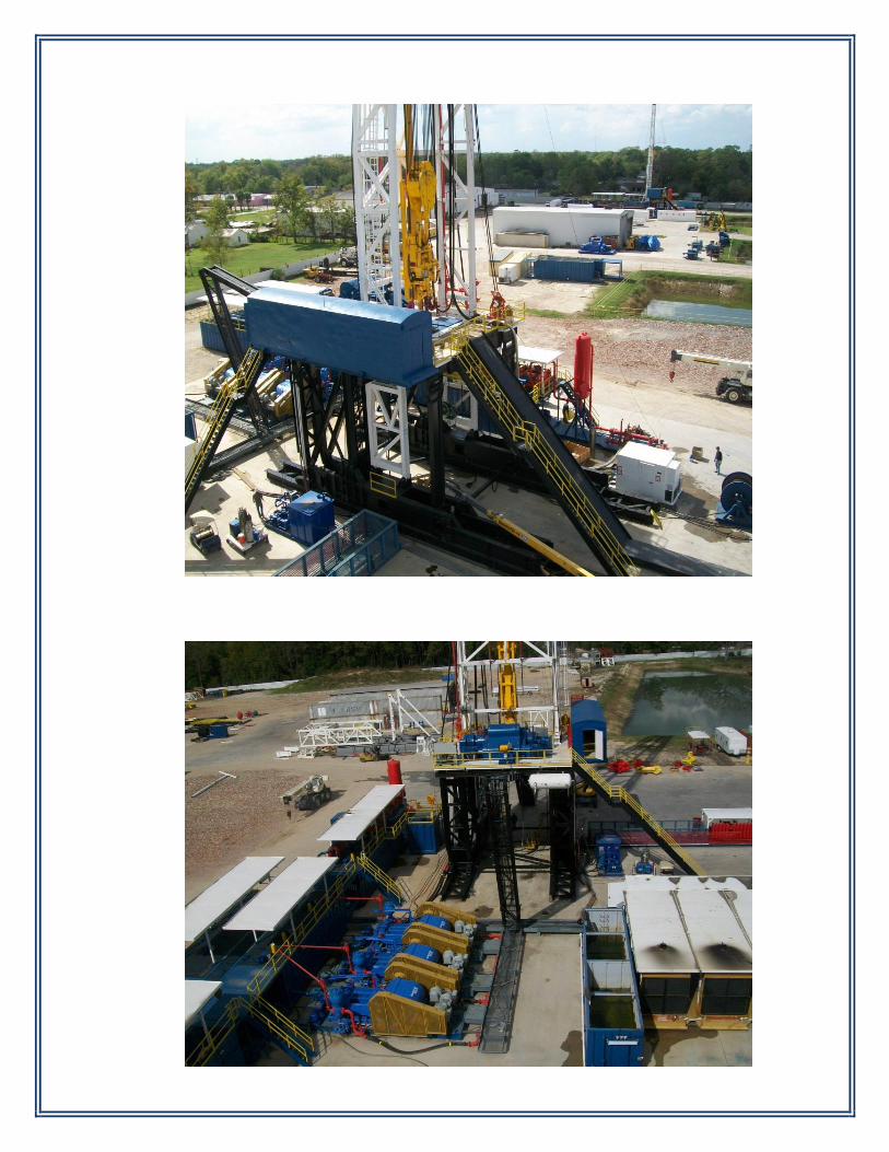
RIG STRUCTURES AND EQUIPMENT ASSEMBLY AND RIG-UP: The rig shall be assembled as close to actual rig site assembly with all
interconnections including accumulator lines, choke manifold lines, brake cooling system, flow lines from bell nipple to shale shaker. Equipment shall be laid out as shown on the rig layout drawing.
Page 20
TESTING:
The rig system shall be tested at the rig-up yard. Testing shall be witnessed by the Client and/or its representative.
DISASSEMBLY AND LOAD OUT:
After testing and acceptance, the rig shall be disassembled and cleaned –up for shipment. Touch-up painting and minor repairs of damage spots due to rig-up and handling shall be performed and then loaded out.
DOCUMENTATIONS, MANUALS, WARRANTIES, AND API CERTIFICATIONS:
BHL shall provide (3) sets of Operations and Maintenance Manuals, Drawing Arrangements and Assemblies of the rig components, Erection Procedures, Warranties, and API Certifications.
ENGINEERING PROJECT MANAGEMENT RIG SITE ACCOMMODATIONS: (NOT INCLUDED) FORKLIFTS: (R) (NOT INCLUDED) CRANES: (R) (NOT INCLUDED) MANLIFT: (R) (NOT INCLUDED)
END OF INVENTORY