Embed Size (px)
Citation preview
CV-900 / CV-1800 / CV-2800HEAVY DUTY PROFESSIONAL AMPLIFIERS
USER MANUAL
IMPORTANT SAFETY INSTRUCTIONS
1. Read Instructions – All the safety and operating instructions should be read beforethis product is operated.
2. Retain Instructions – The safety and operating instructions should be retained forfuture reference.
3. Heed Warnings – All warnings on the appliance and in the operating instructionsshould be adhered to.
4. Follow Instructions – All operating and use instructions should be followed.
5. Do not use this amplifier near water. The amplifier should not be used near wateror moisture or dripping or splashing — for example, in a wet basement, in therain, or near a swimming pool. Objects that contain liquids, such as vases, shallnot be placed on the ampllifier.
6. Clean only with dry cloth.
7. Do not block any ventilation openings. Pleaase install in a well ventilatedenvironment.
8. Do not install near any heat sources such as radiators, heat registers, stoves, orother apparatus (including amplifiers) that produce heat.
9. Do not defeat the safety purpose of the polarized or gounding plug. A polorizedplug has two lnades with one wider than the other. A grounding plug has twoblades and third prong. The wide blasde or the third prong is provided for safety.If the provided plug does not fit into your outllet, consult an electician forreplacement of the obsolete outlet.
10. WARNING: The mains plug or amplifier power inlet is used as a disconnetdevice, the disconnect device shall remain readily operable. Protect the powercord from being walkied on or pinched particularly at theplugs, conenience receptacles, and at the point where they exit from the amplifier.
11. Use only attachments/accessories specified by the manufacturer.
12. Use this amplifier only withcarts and rack equipment ratedfor this type of equipment. When a cart or rack is used usecaution when moving to avoid injury from a tip-over.
13. Unplug the amplifier during lightening storms or whenunused for longperiods of time.
14. Refer all servicing to qualified personnel. Servicing is required when theamplifier has been damaged in any way, such as the power cord is damaged,objects have fallen into the amplifier, the amplifier has been exposed to rain ormoisture, has been dropped or does not operate normally.
16.This amplifier should only be operated from the type of power source indicatedon the rating label. If you are not sure of the type of power coming from your wallsocket, consult your product dealer or local power company.
!7. WARNING: to prevent hazardous electrical shcok do not touch the conductiveparts of the out put terminals. The external wiring connected to these terminalsrequires installation by a qualified technician.
18. This product is in compliance with EU WEEEE regulations.Disposal of end of life of product shoud not be treated asmunicipal waste. Please refer to your local regulations forinstructions on proper disposal of this product.
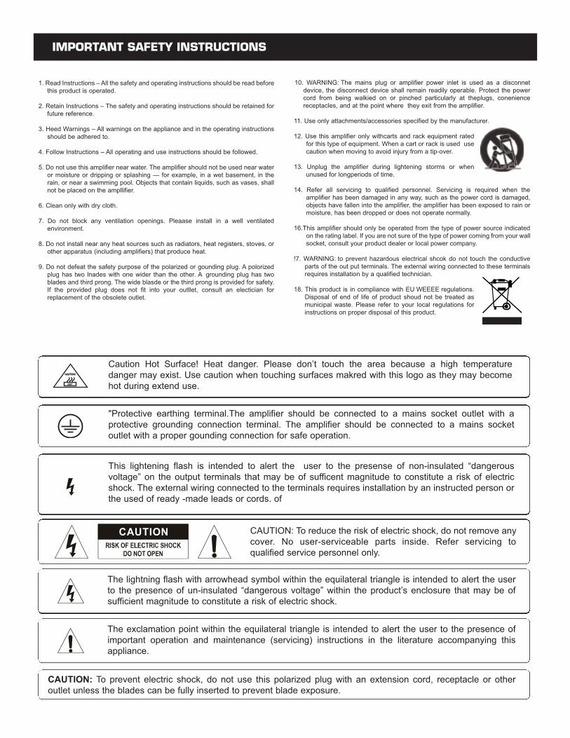
CAUTION: To reduce the risk of electric shock, do not remove anycover. No user-serviceable parts inside. Refer servicing to qualified service personnel only.
The lightning flash with arrowhead symbol within the equilateral triangle is intended to alert the userto the presence of un-insulated “dangerous voltage” within the product’s enclosure that may be ofsufficient magnitude to constitute a risk of electric shock.
The exclamation point within the equilateral triangle is intended to alert the user to the presence ofimportant operation and maintenance (servicing) instructions in the literature accompanying this appliance.
CAUTION: To prevent electric shock, do not use this polarized plug with an extension cord, receptacle or otheroutlet unless the blades can be fully inserted to prevent blade exposure.
"Protective earthing terminal.The amplifier should be connected to a mains socket outlet with aprotective grounding connection terminal. The amplifier should be connected to a mains socketoutlet with a proper gounding connection for safe operation.
Caution Hot Surface! Heat danger. Please don’t touch the area because a high temperature danger may exist. Use caution when touching surfaces makred with this logo as they may becomehot during extend use.
This lightening flash is intended to alert the user to the presense of non-insulated “dangerousvoltage” on the output terminals that may be of sufficent magnitude to constitute a risk of electricshock. The external wiring connected to the terminals requires installation by an instructed person orthe used of ready -made leads or cords. of
3
INTRODUCTION
Thank you for your decision to purchase Cerwin-vega’s innovative new CV Series professional power amplifier! Engineered for superiorsound reproduction, the CV Series line of professional amplifiers deliver top quality audio at an affordable price. The CV Series offer a stan-dard of reliability and efficiency that makes them the perfect solution for every DJ, musician, and sound engineer. Welcome to a new levelof professional quality sound performance!
UNPACKING & INSTALLATION
Although it is neither complicated to install, nor difficult to operate your amplifier, a few minutes of your time are required to read this man-ual for a properly wired installation, and to become familiar with the unit’s features. Please take great care in unpacking the unit and donot discard the carton and other packing materials. They may be needed when moving the unit and are required if it ever becomes nec-essary to return the unit for service. Never place the unit near a radiator, in front of heating vents, in direct sunlight, in excessive humid-ity, or dusty locations to avoid damages and to guaranty a long reliable use. Connect the unit with the system components according tothe description on the following pages.
FEATURES
• Cerwin-vega amplifiers deliver the following power ratings.
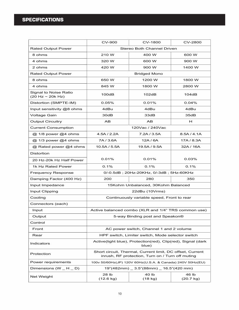
• CV-900 - 2 x 210 Watts at 8 ohm, 2 x 320 Watts at 4 ohm and 2 x 420 Watts at 2 ohm• CV-1800 - 2 x 400 Watts at 8 ohm, 2 x 600 Watts at 4 ohm and 2 x 900 Watts at 2 ohm• CV-2800 - 2 x 600 Watts at 8 ohm, 2 x 900 Watts at 4 ohm and 2 x 1400 Watts at 2 ohm
• 2-channel, parallel or bridged mono operating modes for flexible application 900 Watts for CV-900, 1800 Watts for CV-1800 and 2800Watts for CV-2800
• Independent limiters for each channel reduce overload distortion
• Independent input level controls for each channel allow precision adjustments
• Precise signal and clip LED indicators to monitor performance, allow you to correct for overloading (clipping) condition
• Low-frequency filters (40 Hz) remove rumble and subsonic frequencies
• Twin-tunnel and two temperature-sensitivity forced-air cooling system to maintain a low operating temperature during use
• Balanced XLR or balanced 1/4-inch TRS Combination input connector for each channel and LINK ports
• 5-way output binding posts or Speakon® connectors enable secure operation
• High-current toroidal transformer for absolute reliability
• Independent DC and thermal overload protection on each channel automatically protects amplifier and speaker from damage or failure
• The CV-Series can be mounted in any standard 19” rack
4
FRONT PANEL CONTROLS
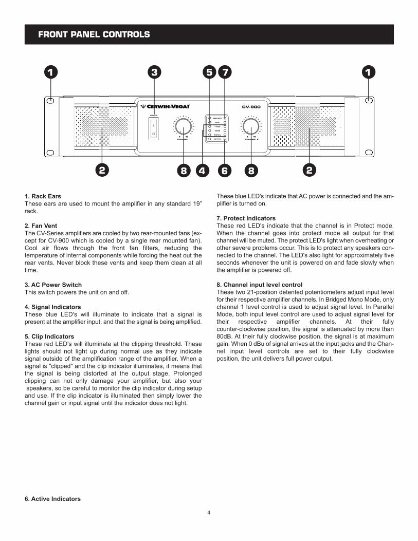
1. Rack EarsThese ears are used to mount the amplifier in any standard 19”rack.
2. Fan VentThe CV-Series amplifiers are cooled by two rear-mounted fans (ex-cept for CV-900 which is cooled by a single rear mounted fan).Cool air flows through the front fan filters, reducing thetemperature of internal components while forcing the heat out therear vents. Never block these vents and keep them clean at alltime.
3. AC Power SwitchThis switch powers the unit on and off.
4. Signal IndicatorsThese blue LED's will illuminate to indicate that a signal ispresent at the amplifier input, and that the signal is being amplified.
5. Clip IndicatorsThese red LED's will illuminate at the clipping threshold. Theselights should not light up during normal use as they indicatesignal outside of the amplification range of the amplifier. When asignal is "clipped" and the clip indicator illuminates, it means thatthe signal is being distorted at the output stage. Prolongedclipping can not only damage your amplifier, but also yourspeakers, so be careful to monitor the clip indicator during setupand use. If the clip indicator is illuminated then simply lower thechannel gain or input signal until the indicator does not light.
6. Active Indicators
These blue LED's indicate that AC power is connected and the am-plifier is turned on.
7. Protect IndicatorsThese red LED's indicate that the channel is in Protect mode.When the channel goes into protect mode all output for thatchannel will be muted. The protect LED's light when overheating orother severe problems occur. This is to protect any speakers con-nected to the channel. The LED's also light for approximately fiveseconds whenever the unit is powered on and fade slowly whenthe amplifier is powered off.
8. Channel input level controlThese two 21-position detented potentiometers adjust input levelfor their respective amplifier channels. In Bridged Mono Mode, onlychannel 1 level control is used to adjust signal level. In ParallelMode, both input level control are used to adjust signal level fortheir respective amplifier channels. At their fullycounter-clockwise position, the signal is attenuated by more than80dB. At their fully clockwise position, the signal is at maximumgain. When 0 dBu of signal arrives at the input jacks and the Chan-nel input level controls are set to their fully clockwiseposition, the unit delivers full power output.
5
REAR PANEL CONTROLS
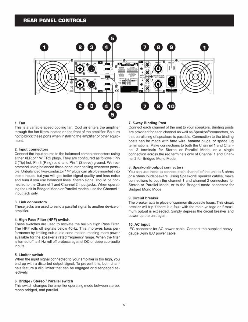
1. FanThis is a variable speed cooling fan. Cool air enters the amplifierthrough the fan filters located on the front of the amplifier. Be surenot to block these ports when installing the amplifier or other equip-ment.
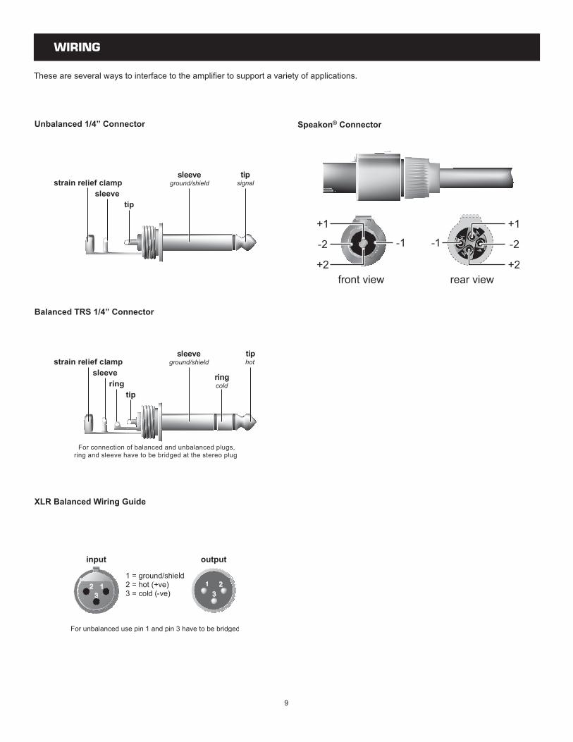
2. Input connectorsConnect the input source to the balanced combo connectors usingeither XLR or 1/4” TRS plugs. They are configured as follows : Pin2 (Tip) hot, Pin 3 (Ring) cold, and Pin 1 (Sleeve) ground. We rec-ommend using balanced three-conductor cabling wherever possi-ble. Unbalanced two-conductor 1/4” plugs can also be inserted intothese inputs, but you will get better signal quality and less noiseand hum if you use balanced lines. Stereo signal should be con-nected to the Channel 1 and Channel 2 input jacks. When operat-ing the unit in Bridged Mono or Parallel modes, use the Channel 1input jack only.
3. Link connectorsThese jacks are used to send a parallel signal to another device oramplifier.
4. High Pass Filter (HPF) switch.These switches are used to activate the built-in High Pass Filter.The HPF rolls off signals below 40Hz. This improves bass per-formance by limiting sub-audio cone motion, making more poweravailable for the speaker’s rated frequency range. When the filteris turned off, a 5 Hz roll off protects against DC or deep sub-audioinputs.
5. Limiter switchWhen the input signal connected to your amplifier is too high, youend up with a distorted output signal. To prevent this, both chan-nels feature a clip limiter that can be engaged or disengaged se-lectively.
6. Bridge / Stereo / Parallel switchThis switch changes the amplifier operating mode between stereo,mono bridged, and parallel.
7. 5-way Binding PostConnect each channel of the unit to your speakers. Binding postsare provided for each channel as well as Speakon® connectors, sothat paralleling of speakers is possible. Connection to the bindingposts can be made with bare wire, banana plugs, or spade lugterminations. Make connections to both the Channel 1 and Chan-nel 2 terminals for Stereo or Parallel Mode, or a singleconnection across the red terminals only of Channel 1 and Chan-nel 2 for Bridged Mono Mode.
8. Speakon® output connectorsYou can use these to connect each channel of the unit to 8 ohmsor 4 ohms loudspeakers. Using Speakon® speaker cables, makeconnections to both the channel 1 and channel 2 connectors forStereo or Parallel Mode, or to the Bridged mode connector forBridged Mono Mode.
9. Circuit breakerThe breaker acts in place of common disposable fuses. This circuitbreaker will trip if there is a fault with the main voltage or if maxi-mum output is exceeded. Simply depress the circuit breaker andpower up the unit again.
10. AC inputIEC connector for AC power cable. Connect the supplied heavy-gauge 3-pin IEC power cable.
6
PROTECTION
Every model in the CV-Series incorporates protection features. The front panel Protection LED indicates the activity of the speakerconnection relay circuitry in each channel. When the protection LED turns on, this circuitry is active, and all connected speakers are muted.
Initial power-up : For approximately five seconds after initialpower-up, the protection circuitry is activated and the speaker out-puts are muted. If everything is operating normally, you will hear anaudible click at the conclusion of this brief period, as the protectioncircuitry is deactivated and the unit begins delivering signal to theconnected speakers. It is normal for the Protection LED to fadegradually after the amplifier is powered off.
Thermal Protection : Abnormally high heat sink temperatures willengage the protection circuitry for the overheating channel only.An output relay disconnects the speakers until normal tempera-ture range is restored. The Protect indicator will light to show theprotection circuit is active. To guard against this problem, makesure the unit receives adequate ventilation on all sides and thatboth the front and rear panels are unobstructed. If the power trans-former gets too hot, its thermal switch will disconnect all of the sec-ondary power and disconnect both channel outputs.
Short circuit : If output is shorted due to faulty wiring, the thermalcircuitry will automatically protect the amplifier. If this occurs, theload will be disconnected by the thermal protection circuitry.
DC Voltage Protection : If an amplifier channel detects DC volt-age at the speaker output, the output relay will immediately opento prevent speaker damage.
Subsonic Frequency Protection : The built-in High Pass Filterprovides subsonic frequency protection for each channel.
Current limiting Protection : At the amplifier’s full power limit, orclipping point, the limiter circuitry will be activated. This is indicatedby illumination of the Clip LED. The channel gain is automaticallyreduced, protecting the speakers from high power. Uncontrolledfeedback, oscillations, or improper equipment gain setting may ac-tivate this circuitry, which is virtually transparent in operation as fullsignal bandwidth is maintained.
There is reason to be concerned any time the Protection LED lightsup (except for initial power-up during approximately five seconds).If this occurs, turn the amplifier off immediately and check all wiringand external equipment carefully in order to locate and correct thecondition.
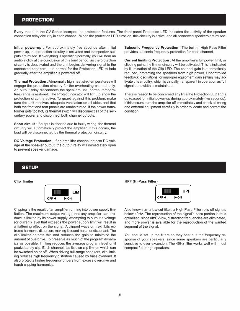
Clipping is the result of an amplifier running into power supply lim-itation. The maximum output voltage that any amplifier can pro-duce is limited by its power supply. Attempting to output a voltage(or current) level that exceeds the power supply limit will result ina flattening effect on the signal. A clipped waveform exhibits ex-treme harmonic distortion, making it sound harsh or dissonant. Theclip limiter detects this and reduces the gain to minimize theamount of overdrive. To preserve as much of the program dynam-ics as possible, limiting reduces the average program level untilpeaks barely clip. Each channel has its own clip limiter, which canbe switched on or off. When driving full-range speakers, clip limit-ing reduces high frequency distortion caused by bass overload. Italso protects higher frequency drivers from excess overdrive andharsh clipping harmonics.
Clip limiter
Also known as a low-cut filter, a High Pass Filter rolls off signalsbelow 40Hz. The reproduction of the signal’s bass portion is thusoptimized, since ultrCV-low, distracting frequencies are eliminated,and more power is available for the reproduction of the wantedsegment of the signal.
You should set up the filters so they best suit the frequency re-sponse of your speakers, since some speakers are particularlysensitive to over-excursion. The 40Hz filter works well with mostcompact full-range speakers.
HPF (Hi-Pass Filter)
SETUP
7
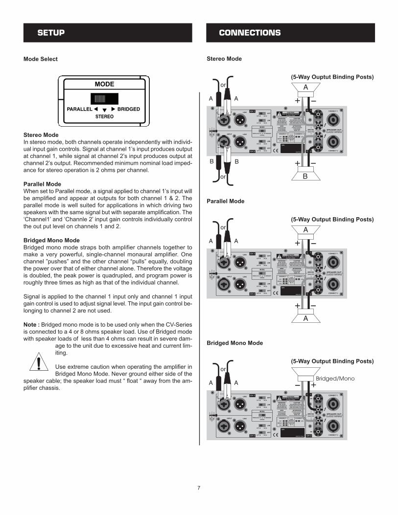
Stereo ModeIn stereo mode, both channels operate independently with individ-ual input gain controls. Signal at channel 1’s input produces outputat channel 1, while signal at channel 2’s input produces output atchannel 2’s output. Recommended minimum nominal load imped-ance for stereo operation is 2 ohms per channel.
Parallel ModeWhen set to Parallel mode, a signal applied to channel 1’s input willbe amplified and appear at outputs for both channel 1 & 2. Theparallel mode is well suited for applications in which driving twospeakers with the same signal but with separate amplification. The‘Channel1’ and ‘Channle 2’ input gain controls individually controlthe out put level on channels 1 and 2.
Bridged Mono ModeBridged mono mode straps both amplifier channels together tomake a very powerful, single-channel monaural amplifier. Onechannel ”pushes” and the other channel “pulls” equally, doublingthe power over that of either channel alone. Therefore the voltageis doubled, the peak power is quadrupled, and program power isroughly three times as high as that of the individual channel.
Signal is applied to the channel 1 input only and channel 1 inputgain control is used to adjust signal level. The input gain control be-longing to channel 2 are not used.
Note : Bridged mono mode is to be used only when the CV-Seriesis connected to a 4 or 8 ohms speaker load. Use of Bridged modewith speaker loads of less than 4 ohms can result in severe dam-
age to the unit due to excessive heat and current lim-iting.
Use extreme caution when operating the amplifier inBridged Mono Mode. Never ground either side of the
speaker cable; the speaker load must “ float “ away from the am-plifier chassis.
Stereo Mode
CONNECTIONS
(5-Way Ouptut Binding Posts)
Parallel Mode
(5-Way Output Binding Posts)
Bridged Mono Mode
(5-Way Output Binding Posts)
SETUP
Mode Select
8
CONNECTIONS
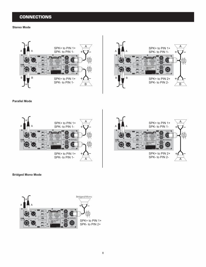
Stereo Mode
B
A
Parallel Mode
B
A
Bridged Mono Mode
B
B
SPK+ to PIN 1+SPK- to PIN 1-
SPK+ to PIN 1+SPK- to PIN 1-
SPK+ to PIN 1+SPK- to PIN 1-
SPK+ to PIN 2+SPK- to PIN 2-
SPK+ to PIN 1+SPK- to PIN 1-
SPK+ to PIN 1+SPK- to PIN 1-
SPK+ to PIN 1+SPK- to PIN 1-
SPK+ to PIN 2+SPK- to PIN 2-
SPK+ to PIN 1+SPK- to PIN 2+
9
WIRING
These are several ways to interface to the amplifier to support a variety of applications.
Unbalanced 1/4” Connector
Balanced TRS 1/4” Connector
XLR Balanced Wiring Guide
Speakon® Connector
10
SPECIFICATIONS
11
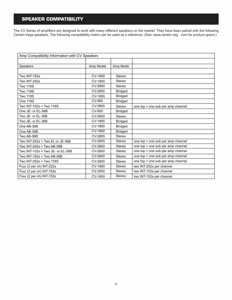
SPEAKER COMPATIBILITY
The CV Series of amplifiers are designed to work with many different speakers on the market. They have been paired with the followingCerwin-Vega speakers. The following compatibility matrix can be used as a reference. (See: www.cerwin-veg com for product specs.)