Embed Size (px)
Citation preview

HEAVY DUTY SERVICEINDUSTRIAL TIE ROD CONSTRUCTION
NOMINAL PRESSURE - 3000 PSI
STANDARD BORE SIZES 1.5” THROUGH 20”
PISTON ROD DIAMETERS 5/8” THROUGH 10”
18 STANDARD MOUNTING STYLES
STARNITETM AVAILABLE ON ALL STEEL PARTS
HEAVY DUTYHydraulic Cylinders
STAR6SERIES

Cylinder Design Features,Standard Piston
ST6 SERIES Heavy Duty Hydraulic Cylinders
STARCYL CYLINDERS PAGE 2
Piston Rod from 5/8” to 3” dia●High Strength Alloy Steel (SAE4140). STARNITETM (Nitrocarburation)
treatment on the rod gives better corrosion-resistant properties (out performs 12-micron, (.0005 in.) chromium electroplating by ratio up
to 20:1.), Improved wear resistance, better lubrication retention, dent resistance without induction hardening (65-70Rc), environmentally friendly, no surface pitting, flaking, or hydrogen embrittlement. The
finish created by the process is a lustrous black. (available up to 6 ft of stroke) (Available in Stainless Steel)
Piston Rod from 3.5”dia to 10” dia ●Induction Hard Chromed Steel (100Ksi Min Yiled)
Wiper ●The Hythane wiper is designed to wipe off abrasive dust and contami-
nants on the retract stroke to ensure long life for the seals, rod bushing and piston rod. (temperature: -50° to 230°F)
One-Piece Iron Piston (U-cup Design) Std. ● One piece design for maximum strength and bearing surface.
Anaerobic adhesive is used to permanently lock and seal the piston to the rod. 3 different styles of piston available.
***Piston Wear Ring *** ●Nylon material is designed for low friction, and to ensure minimum wear
in the cylinder’s tubing in side load application. Eliminates metal-to-metal contact.
O-ring/Backup Tube End Seals ●Nitrile O-ring design is pressure compensating and reusable. Pressure-
actuated cylinder body-to-head and cap. Backup ring to preventextrusion of the oring .
Rod lips seal ●Our New Design with a real rod u-cup (Hythane) is completely self com-pensating for zero leakage at all pressures (temperature: -50° to 230°F)
Self Centering Cushion Spud ●Self centering design allows for close tolerance and min. wear. For
faster cycle time and increased productivity, maximum performance, economical, flexible for even the most demanding applications, reduces shock and machine noise, lower maintenance costs, can be supplied at
head, cap or both ends.
Piston Lip Seal (std) ●Lip-type low friction Hythane piston seals are pressure energized and wear compensating for low friction and long life (temperature: -50° to
230°F)
*All Blue seals can withstand most chemical washdown, No Fluorocarbon Required
Porting ●SAE Straight thread “O”Ring Ports are standard. NPT ports are op-tional at no extra cost. Standard port position is number 1. Specify if another location is needed. SAE Code 61 ports are also available.

Cylinder Design Features, Hi-load Piston
ST6 SERIES Heavy Duty Hydraulic Cylinders
STARCYL CYLINDERS PAGE 3
Piston Seal (Hi-Load Option) ●Compact double acting piston seal assembly
designed for one piece pistons and is suitable for low to high pressure,medium to heavy duty applications.
The assembly comprises as standard
Tie rods ●Corrosion resistant STARNITE (Nitrocarburation), stress proof steel
maintains uniform compression on tube end seals (max 6 ft of stroke).
The Cylinder Body ●Heavy wall steel tubing, honed to a micro finish bore. Tube ends are
machined on the OD concentric with the ID. They are confined by the close tolerance machining of the head and cap which provides greater
hoop strength.(STARNITETM available for hard layer ID max 6ft of stoke),
Precision Steel Head & Cap ●Precision machined Concentric with flat and parallel surfaces. Provides
true aligment of tubing and rod gland. (available in STARNITETM)
Rod Gland ●Starnite Cast iron gland is externally removable without cylinder disas-
sembly for easy maintenance. Designed to provide maximum rod bearing. The New STARNITETM Cast Iron This bushing has been
designed for tough application with side load. The STARNITE Technol-ogy improves bearing resistance against wear with an hardened Layer
on both parts.
One-Piece Iron Piston (Hi-Load Option) ●One piece design for maximum strength and bearing surface.
Anaerobic adhesive is used to permanently lock and seal the piston to the rod. 3 different styles of piston available.
Extra Large Piston Wear Ring (Hi-Load Option) ●Nylon material is designed for low friction, and to ensure minimum wear
in the cylinder’s tubing in side load application. Eliminates metal-to-metal contact.
Hex. Rod Ends ●Standard 6 Flats Hexagonal rod end, for easy access of the rod with
tools
Adjustable screw for Cushion ●Adjustable Floating Stepped Cushions – For maximum
performance – economical and flexible for even the most demandingapplications – provides superior performance in reducing shock.
Cushions are optional and can be supplied at head end, cap end, orboth ends without change in envelope or mounting dimensions.

StarNite ProcessST6 SERIES Heavy Duty Hydraulic Cylinders
STARCYL CYLINDERS PAGE 4
88 h
88 h 336 h
0
10
20
30
40
50
60
70
80
90
100
SurfaceArea
Corroded (%)
Hard Chrome Electro-lessNickel
Nitrotec STARNITE
Surface Treatement
Corrosion Resistance EvaluationTest conditions; Spool Shaft, ASTM B-117,
(88h)test hours
88 h
High wear resistance, as well as excellent sliding and running properties, is obtained through STARNITETM treatment. The service life of cylinders parts is extended. The finish created by the STARNITETM process is a lustrous black.
During the process, which takes place at 1075°F, the metal surface is enriched with nitrogen and carbon. A two part nitride layer consisting of a monophase compound layer and a diffusion layer is formed. Total depth ranges from 0.008-0.040”, depending on composition of the base material and treating time. Hardness in the compound layer ranges from approximately HV 700 (60 Rc) to about HV 1600 for high alloyed tools steel. As part of the salt-bath nitriding and QPQP (Quench-Polish & Quench & Polish) sequence, finish-machine parts are polished and chemically processed to produce a highly corrosion-resistant surface with a finish suitable for bearing or seal-type applications.
Chromed plated cylinders STARNITETM
Process on cylinders• Chrome plate can flake and blister. • Superior corrosion resistance.
• Flakes and slivers will destroy seals and glands. • Improved wear resistance.
• Better lubrication retention.• Loose chrome will cause massive leaking and
rapid system failure. • Dent resistance without induction hardening.
• Environmentally Friendly
• Chrome lacks dimensional uniformity. • No surface pitting, flaking, or hydrogen embrittlement.
• INCREASED SERVICE LIFE.
Chrome plated Vs STARNITETM
Great concern exists in North America community regarding many critical materials because of North America’ reliance on metals that are not native to this continent. Some 91% of the chromium used here is imported (9% balance from recycling). STARNITETM process provides at least a partial solution to this problem and because it is not a plating or a coating but in the steel itself the process offers superior performance.
Corrosion resistance developed by the STARNITETM technique out performs 12-micron (.0005 in.) chromium electroplating by ratio up to 20:1, and 20 micron (.0008 in.) nickel plating by a factor of 8:1.
ENVIRONMENTALLY & ECONOMICALLY SAFE
STARNITE ThE ANSwER To wEAR, coRRoSIoN ANd fATIguE pRoblEmS
The STARNITETM process improves component properties.

Tie rods Head endST6X3
NFPA MX3 page 6
Tie rods Cap endST6X2
NFPA MX2 page 6
Tie rods Extended Both endsST6X1
NFPA MX1 page 6
Head Rectangular FlangeST6F1
NFPA MF1 page 8Head Square FlangeST6F5
NFPA MF5 page 8
Head Rectangular MountST6E5
NFPA ME5 page 8
Cap Rectangular FlangeST6F2
NFPA MF2 page 10
Cap Square FlangeST6F6
NFPA MF6 page 10Cap Rectangular MountST6E6
NFPA ME6 page 10
Side LugsST6S2
NFPA MS2 page 12
Center LugsST6S3
NFPA MS3 page 12
Side Tap ST6S4
NFPA MS4 page 12End AnglesST6S1
NFPA MS1 page 14
End LugsST6S7
NFPA MS7 page 14
Cap Fixed ClevisST6P1
NFPA MP1 page 14
Head TrunnionST6T1
NFPA MT1 page 16Cap TrunnionST6T2
NFPA MT2 page 16
Intermediate TrunnionST6T4
NFPA MT4 page 16
Spherical BearingST6SB
page 20
Double Rod CylindersST6D
page 23
Standard Specifications
HeavyDuty Service – ANSI/(NFPA) T3.6.7R2 - 1996Specifications and Mounting Dimensions StandardStandard Construction: Square Head, Tie Rod DesignNominal Pressure : 3000 PSI*Standard Fluid: Hydraulic OilStandard Temperature :-40°F to +230°F**Bore Sizes from 1.5” through 6”Piston Rod Diameter from 5/8” through 4”
Mounting Styles: 18 standard styles at various applica-tion ratingsStrokes : Available in any practical stroke lengthCushions : Optional at either end or both ends of stroke.Float Check at cap end.Rod Ends :Three Standard Choices – Specials to Order
* See page 63 for more details on Pressure rating per bore. ** See page 64 Viton seals for higher temperature service.
Specification & Mountings
See page 18, 19 and 20 For Spherical Bearing Mount Style ST6SB.
ST6 SERIES Heavy Duty Hydraulic Cylinders
STARCYL CYLINDERS PAGE 5

Tie rod Mountings 1 1/2 to 6” Bore Sizes
KK
D WRENCH FLATS
B
C
W
MM
A
V
LA
KK THDA DEEP
D WRENCH FLATS
B
CV
MM
W
D WRENCH FLATS
CC
V
W
C
MMB
LA
KK
D WRENCH FLATS
B
C
W
MM
A
V
LA
KK THDA DEEP
D WRENCH FLATS
B
CV
MM
W
D WRENCH FLATS
CC
V
W
C
MMB
LA
KK
D WRENCH FLATS
B
C
W
MM
A
V
LA
KK THDA DEEP
D WRENCH FLATS
B
CV
MM
W
D WRENCH FLATS
CC
V
W
C
MMB
LA
ST6 SERIES Heavy Duty Hydraulic Cylinders
STARCYL CYLINDERS
A high strength rod end stud is supplied on thread style #2 through 1” diameter rods and on thread style #1 through 1” diameter rods. Larger sizes or special rod ends are cut threads. Style #2 rod ends are recommended where the workpiece is secured against the rod shoulder. When the workpiece is not shouldered, style 4 rod ends are recommended through 2” piston rod diameters and style #1 rod ends are recommended on larger diameters. Use style #4 for applications where female rod end threads are required. If rod end is not specified, style #2 will be supplied
“Specials” Thread Style #XTo order, specify “Style #X” and give desired dimensions for CC or KK, A and LA. If otherwise special, furnish dimensional sketch.
Rod End Dimensions—see table 2
Thread Style #2(NFPA Style SM)Small Male
Thread Style #1(NFPA Style IM)Intermediate Male
Thread Style #4(NFPA Style SF)Small Female
PAGE 6
P + STROKE Y
EE
MM ROD DIA
EE DD
ZB + STROKE
K BBFGJ
LB + STROKE W
ZJ + STROKE
3
1
24 ER
Basic Mounting ST6X0 — NFPA MX0 — no tie rods extended can be supplied upon request.
Tie Rods Extended Head EndStyle ST6X3(NFPA Style MX3)
Tie Rods Extended Cap EndStyle ST6X2(NFPA Style MX2)
Tie Rods Extended Both EndStyle ST6X1(NFPA Style MX1)
P + STROKE Y
EE
MM ROD DIA
EE
DD
KBB
K
ZJ + STROKE
FGJ
LB + STROKE W
ZB + STROKE
WF
3
1
24 ER
P + STROKE Y
1
2
3
4 ER
MM ROD DIA
EE EE
DD
K
FGJ
LB + STROKE W
ZB + STROKE
BB BB
ZJ + STROKE

BORE AA BB DD EEE
F G J K RADD STROKE
NPTF* SAEstd LB P1 1/2 2.3 1 3/8 3/8-24 2 1/2 1/2 10 3/8 1 3/4 1 1/2 3/8 1.63 5 2 7/8
2 2.9 1 13/16 1/2-20 3 1/2 10 5/8 1 3/4 1 1/2 7/16 2.05 5 1/4 2 7/82 1/2 3.6 1 13/16 1/2-20 3 1/2 1/2 10 5/8 1 3/4 1 1/2 7/16 2.55 5 3/8 33 1/4 4.6 2 5/16 5/8-18 4 1/2 3/4 12 3/4 2 1 3/4 9/16 3.25 6 1/4 3 1/2
4 5.4 2 5/16 5/8-18 5 3/4 12 7/8 2 1 3/4 9/16 3.82 6 5/8 3 3/45 7.0 3 3/16 7/8-14 6 1/2 3/4 12 7/8 2 1 3/4 13/16 4.95 7 1/8 4 1/46 8.1 3 5/8 1-14 7 1/2 1 16 1 2 1/4 2 1/4 7/8 5.73 8 3/8 47/8
BORE ROD SIZE
Thread Style Rod Extensions and pilot dimensions
Y
Add StrokeSTYLE
#1CC
STYLE #2 
KK A±.001
B C D LA NA V W ZB ZJ1 1/2 std 5/8 1/2-20 7/16-20 3/4 1.123 3/8 1/2 1 3/8 9/16 1/4 5/8 2 6 5 5/8
1 7/8-14 3/4-16 1 1/8 1.498 1/2 7/8 2 1/8 15/16 1/2 1 2 3/8 6 3/8 6
2 std 1 7/8-14 3/4-16 1 1/8 1.498 1/2 7/8 1 7/8 15/16 1/4 3/4 2 3/8 6 7/16 61 3/8 1 1/4-12 1-14 1 5/8 1.998 5/8 1 1/8 2 5/8 1 5/16 3/8 1 2 5/8 6 11/16 6 1/4
2 1/2 std 1 7/8-14 3/4-16 1 1/8 1.498 1/2 7/8 1 7/8 15/16 1/4 3/4 2 3/8 6 9/16 6 1/81 3/8 1 1/4-12 1-14 1 5/8 1.998 5/8 1 1/8 2 5/8 1 5/16 3/8 1 2 5/8 6 13/16 6 3/81 3/4 1 1/2-12 1 1/4-12 2 2.373 3/4 1 1/2 3 1/4 1 11/16 1/2 1 1/4 2 7/8 7 1/16 6 5/8
3 1/4 std 1 3/8 1 1/4-12 1-14 1 5/8 1.998 5/8 1 1/8 2 1/2 1 5/16 1/4 7/8 2 3/4 7 11/16 7 1/81 3/4 1 1/2-12 1 1/4-12 2 2.373 3/4 1 1/2 3 1/8 1 11/16 3/8 1 1/8 3 7 15/16 7 3/82 1 3/4-12 1 1/2-12 2 1/4 2.623 7/8 1 11/16 3 1/2 1 15/16 3/8 1 1/4 3 1/8 8 1/16 7 1/2
4 std 1 3/4 1 1/2-12 1 1/4-12 2 2.373 3/4 1 1/2 3 1 11/16 1/4 1 3 8 3/16 7 5/82 1 3/4-12 1 1/2-12 2 1/4 2.623 7/8 1 11/16 3 3/8 1 15/16 1/4 1 1/8 3 1/8 8 5/16 7 3/42 1/2 2 1/4-12 1 7/8-12 3 3.123 1 2 1/16 4 3/8 2 3/8 3/8 1 3/8 3 3/8 8 9/16 8
5 std 2 1 3/4-12 1 1/2-12 2 1/4 2.623 7/8 1 11/16 3 3/8 1 15/16 1/4 1 1/8 3 1/8 9 1/16 8 1/42 1/2 2 1/4-12 1 7/8-12 3 3.123 1 2 1/16 4 3/8 2 3/8 3/8 1 3/8 3 3/8 9 5/16 8 1/23 2 3/4-12 2 1/4-12 3 1/2 3.748 1 2 5/8 4 7/8 2 7/8 3/8 1 3/8 3 3/8 9 5/16 8 1/23 1/2 3 1/4-12 2 1/2-12 3 1/2 4.248 1 3 4 7/8 3 3/8 3/8 1 3/8 3 3/8 9 5/16 8 1/2
6 std 2 1/2 2 1/4-12 1 7/8-12 3 3.123 1 2 1/16 4 1/4 2 3/8 1/4 1 1/4 3 1/2 10 1/2 9 5/83 2 3/4-12 2 1/4-12 3 1/2 3.748 1 2 5/8 4 3/4 2 7/8 1/4 1 1/4 3 1/2 10 1/2 9 5/83 1/2 3 1/4-12 2 1/2-12 3 1/2 4.248 1 3 4 3/4 3 3/8 1/4 1 1/4 3 1/2 10 1/2 9 5/8
4 3 3/4-12 3-12 4 4.748 1 3 3/8 5 1/4 3 7/8 1/4 1 1/4 3 1/2 10 1/2 9 5/8
Tie Rod Mountings 1 1/2 to 6” Bore Sizes
ST6 SERIES Heavy Duty Hydraulic Cylinders
STARCYL CYLINDERS PAGE 7
Table 1—Envelope and Mounting Dimensions
Table 2—Rod DimensionsTable 3—Envelope and Mounting Dimensions
std SAE straight thread ports will be furnished as standard and are indicated by port number.*NPTF ports are available at no extra charge.

KK
D WRENCH FLATS
B
C
W
MM
A
V
LA
KK THDA DEEP
D WRENCH FLATS
B
CV
MM
W
D WRENCH FLATS
CC
V
W
C
MMB
LA
KK
D WRENCH FLATS
B
C
W
MM
A
V
LA
KK THDA DEEP
D WRENCH FLATS
B
CV
MM
W
D WRENCH FLATS
CC
V
W
C
MMB
LA
KK
D WRENCH FLATS
B
C
W
MM
A
V
LA
KK THDA DEEP
D WRENCH FLATS
B
CV
MM
W
D WRENCH FLATS
CC
V
W
C
MMB
LA
ST6 SERIES Heavy Duty Hydraulic Cylinders
STARCYL CYLINDERS
A high strength rod end stud is supplied on thread style #2 through 1” diameter rods and on thread style #1 through 1” diameter rods. Larger sizes or special rod ends are cut threads. Style #2 rod ends are recommended where the workpiece is secured against the rod shoulder. When the workpiece is not shouldered, style 4 rod ends are recommended through 2” piston rod diameters and style #1 rod ends are recommended on larger diameters. Use style #4 for applications where female rod end threads are required. If rod end is not specified, style #2 will be supplied
“Specials” Thread Style #XTo order, specify “Style #X” and give desired dimensions for CC or KK, A and LA. If otherwise special, furnish dimensional sketch.
Rod End Dimensions—see table 2
Thread Style #2(NFPA Style SM)Small Male
Thread Style #1(NFPA Style IM)Intermediate Male
Thread Style #4(NFPA Style SF)Small Female
PAGE 8
Rectangular Flangeand Head Mountings
1 1/2 to 6” Bore Sizes
E
P + STROKE Y
3
1
24 R
TFUF
4 HOLESFB
EE
MM ROD DIA
EE
LB + STROKE W
ZB + STROKE
FGJKWF
Head Rectangular Flange mountingStyle ST6F1(NFPA Style MF1 )
Head Square Flange mountingStyle ST6F5(NFPA Style MF5)
Head Rectangular mountingStyle ST6E5(NFPA Style ME5)
P + STROKE Y
E
EE
MM ROD DIA
EE
LB + STROKE W
ZB + STROKE
FGJKWF
3
1
24
R
TFR
TFUF
UF
8 HOLESFB
E
P + STROKE Y
3
1
24 R
TFUF
4 HOLESFB
EE MM ROD DIAEER
D
K
LAF
GJWF
ZB + STROKE
LG + STROKE FG
KB
RT
C
Bore Size
Max PSI ▬ Push*Rod Size
5/8 1 1 3/8 1 3/4 21 1/2 1500 1000 - - -
2 - 2000 1200 - -2 1/2 - 2000 1100 15003 1/4 - - 1800 1300 1400
4 - - - 1800 13005 - - - - 1300
Rod sizeBore 2 1/2 3 3 1/2 4
4 1700 - - -5 800 1200 1000 -6 1200 800 1000 900
* Maximum pressure rating — push application.
Bore Size
Max PSI ▬ Push*Rod Size
5/8 1 1 3/8 1 3/4 21 1/2 3000 3000 - - -
2 - 3000 3200 - -2 1/2 - 3000 3000 30003 1/4 - - 3000 3000 3000
4 - - - 3000 30005 - - - - 3000
Rod sizeBore 2 1/2 3 3 1/2 4
4 3000 - - -5 3000 3000 3000 -6 3000 2700 3000 2700
* Maximum pressure rating — push application.
For Pressures exeeding those shown please use mounting style ST6F5 or ST6E5

ST6 SERIES Heavy Duty Hydraulic Cylinders
STARCYL CYLINDERS PAGE 9
BORE EEE
F FB G J K R TF UFADD STROKE
NPTF* SAEstd LB LG P1 1/2 2 1/2 1/2 10 3/8 7/16 1 3/4 1 1/2 3/8 1.63 3 7/16 4 1/4 5 4 5/8 2 7/8
2 3 1/2 10 5/8 9/16 1 3/4 1 1/2 7/16 2.05 4 1/8 5 1/8 5 1/4 4 5/8 2 7/82 1/2 3 1/2 1/2 10 5/8 9/16 1 3/4 1 1/2 7/16 2.55 4 5/8 5 5/8 5 3/8 4 3/4 33 1/4 4 1/2 3/4 12 3/4 11/16 2 1 3/4 9/16 3.25 5 7/8 7 1/8 6 1/4 5 1/2 3 1/2
4 5 3/4 12 7/8 11/16 2 1 3/4 9/16 3.82 6 3/8 7 5/8 6 5/8 5 3/4 3 3/45 6 1/2 3/4 12 7/8 15/16 2 1 3/4 13/16 4.95 8 3/16 9 3/4 7 1/8 6 1/4 4 1/46 7 1/2 1 16 1 1 1/16 2 1/4 2 1/4 7/8 5.73 9 7/16 11 1/4 8 3/8 7 3/8 47/8
BO
RE
ROD SIZE
Thread Style Rod Extensions and pilot dimensions
Y WF
Add Stroke
STYLE #1CC
STYLE #2 
KK A±.001
B C D KB LA LAF NA V W RD RT ZB1 1/2 std 5/8 1/2-20 7/16-20 3/4 1.123 3/8 1/2 0 1 3/8 1 3/4 9/16 1/4 5/8 2 1/8 3/8 2 1 6
1 7/8-14 3/4-16 1 1/8 1.498 1/2 7/8 0 2 1/8 2 1/2 15/16 1/2 1 2 1/2 3/8 2 3/8 1 3/8 6 3/8
2 std 1 7/8-14 3/4-16 1 1/8 1.498 1/2 7/8 0 1 7/8 2 1/2 15/16 1/4 3/4 2 1/2 3/8 2 3/8 1 3/8 6 7/161 3/8 1 1/4-12 1-14 1 5/8 1.998 5/8 1 1/8 1/4 2 5/8 3 1/4 1 5/16 3/8 1 3 3/8 2 5/8 1 5/8 6 11/16
2 1/2 std 1 7/8-14 3/4-16 1 1/8 1.498 1/2 7/8 0 1 7/8 2 1/2 15/16 1/4 3/4 2 1/2 3/8 2 3/8 1 3/8 6 9/161 3/8 1 1/4-12 1-14 1 5/8 1.998 5/8 1 1/8 1/4 2 5/8 3 1/4 1 5/16 3/8 1 3 3/8 2 5/8 1 5/8 6 13/161 3/4 1 1/2-12 1 1/4-12 2 2.373 3/4 1 1/2 1/4 3 1/4 3 7/8 1 11/16 1/2 1 1/4 3 1/2 3/8 2 7/8 1 7/8 7 1/16
3 1/4 std 1 3/8 1 1/4-12 1-14 1 5/8 1.998 5/8 1 1/8 1/4 2 1/2 3 1/4 1 5/16 1/4 7/8 3 3/8 2 3/4 1 5/8 7 11/161 3/4 1 1/2-12 1 1/4-12 2 2.373 3/4 1 1/2 1/4 3 1/8 3 7/8 1 11/16 3/8 1 1/8 3 1/2 3/8 3 1 7/8 7 15/162 1 3/4-12 1 1/2-12 2 1/4 2.623 7/8 1 11/16 1/8 3 1/2 4 1/4 1 15/16 3/8 1 1/4 4 5/8 3 1/8 2 8 1/16
4 std 1 3/4 1 1/2-12 1 1/4-12 2 2.373 3/4 1 1/2 1/4 3 3 7/8 1 11/16 1/4 1 3 1/2 3/8 3 1 7/8 8 3/162 1 3/4-12 1 1/2-12 2 1/4 2.623 7/8 1 11/16 1/8 3 3/8 4 1/4 1 15/16 1/4 1 1/8 4 5/8 3 1/8 2 8 5/162 1/2 2 1/4-12 1 7/8-12 3 3.123 1 2 1/16 1/4 4 3/8 5 1/4 2 3/8 3/8 1 3/8 4 1/2 5/8 3 3/8 2 1/4 8 9/16
5 std 2 1 3/4-12 1 1/2-12 2 1/4 2.623 7/8 1 11/16 1/8 3 3/8 4 1/4 1 15/16 1/4 1 1/8 4 5/8 3 1/8 2 9 1/162 1/2 2 1/4-12 1 7/8-12 3 3.123 1 2 1/16 1/4 4 3/8 5 1/4 2 3/8 3/8 1 3/8 4 1/2 5/8 3 3/8 2 1/4 9 5/163 2 3/4-12 2 1/4-12 3 1/2 3.748 1 2 5/8 1/4 4 7/8 5 3/4 2 7/8 3/8 1 3/8 5 1/4 5/8 3 3/8 2 1/4 9 5/163 1/2 3 1/4-12 2 1/2-12 3 1/2 4.248 1 3 1/4 4 7/8 5 3/4 3 3/8 3/8 1 3/8 5 3/4 5/8 3 3/8 2 1/4 9 5/16
6 std 2 1/2 2 1/4-12 1 7/8-12 3 3.123 1 2 1/16 1/4 4 1/4 5 1/4 2 3/8 1/4 1 1/4 4 1/2 5/8 3 1/2 2 1/4 10 1/23 2 3/4-12 2 1/4-12 3 1/2 3.748 1 2 5/8 1/4 4 3/4 5 3/4 2 7/8 1/4 1 1/4 5 1/4 5/8 3 1/2 2 1/4 10 1/23 1/2 3 1/4-12 2 1/2-12 3 1/2 4.248 1 3 1/4 4 3/4 5 3/4 3 3/8 1/4 1 1/4 5 3/4 5/8 3 1/2 2 1/4 10 1/24 3 3/4-12 3-12 4 4.748 1 3 3/8 1/4 5 1/4 6 1/4 3 7/8 1/4 1 1/4 6 1/2 5/8 3 1/2 2 1/4 10 1/2
Table 1—Envelope and Mounting Dimensions
Table 2—Rod Dimensions
Table 3—Envelope and Mounting Dimensions
std SAE straight thread ports will be furnished as standard and are indicated by port number.*NPTF ports are available at no extra charge.
Rectangular Flangeand Head Mountings
1 1/2 to 6” Bore Sizes

KK
D WRENCH FLATS
B
C
W
MM
A
V
LA
KK THDA DEEP
D WRENCH FLATS
B
CV
MM
W
D WRENCH FLATS
CC
V
W
C
MMB
LA
KK
D WRENCH FLATS
B
C
W
MM
A
V
LA
KK THDA DEEP
D WRENCH FLATS
B
CV
MM
W
D WRENCH FLATS
CC
V
W
C
MMB
LA
KK
D WRENCH FLATS
B
C
W
MM
A
V
LA
KK THDA DEEP
D WRENCH FLATS
B
CV
MM
W
D WRENCH FLATS
CC
V
W
C
MMB
LA
ST6 SERIES Heavy Duty Hydraulic Cylinders
STARCYL CYLINDERS
A high strength rod end stud is supplied on thread style #2 through 1” diameter rods and on thread style #1 through 1” diameter rods. Larger sizes or special rod ends are cut threads. Style #2 rod ends are recommended where the workpiece is secured against the rod shoulder. When the workpiece is not shouldered, style 4 rod ends are recommended through 2” piston rod diameters and style #1 rod ends are recommended on larger diameters. Use style #4 for applications where female rod end threads are required. If rod end is not specified, style #2 will be supplied
“Specials” Thread Style #XTo order, specify “Style #X” and give desired dimensions for CC or KK, A and LA. If otherwise special, furnish dimensional sketch.
Rod End Dimensions—see table 2
Thread Style #2(NFPA Style SM)Small Male
Thread Style #1(NFPA Style IM)Intermediate Male
Thread Style #4(NFPA Style SF)Small Female
PAGE 10
Rectangular Flangeand Cap Mountings
1 1/2 to 6” Bore Sizes
P + STROKE Y
EE
MM ROD DIA
EE
ZF + STROKE
F K
XF + STROKE
FGJ
LB + STROKE W
WF
E
TF
R
UF
4 HOLESFB
Cap Rectangular Flange mountingStyle ST6F2(NFPA Style MF2 )
Cap Square Flange mountingStyle ST6F6(NFPA Style MF6)
Cap Rectangular mountingStyle ST6E6(NFPA Style ME6)
P + STROKE Y
EEE
MM ROD DIA
EE
ZF + STROKE
WFF
KFGJ
LB + STROKE W
XF + STROKERTF
RTFUF
UF
8 HOLESFB
P + STROKE Y
E
EE
MM ROD DIA
EELB + STROKE W
XF + STROKE
KFGJWF
R
TFUF
4 HOLESFB
Bore Size
Max PSI ▬ Pull*Rod Size
5/8 1 1 3/8 1 3/4 21 1/2 2500 3000 - - -
2 - 3000 3000 - -2 1/2 - 3000 3000 30003 1/4 - - 3000 3000 3000
4 - - - 3000 30005 - - - - 2000
Rod sizeBore 2 1/2 3 3 1/2 4
4 3000 - - -5 3000 2000 3000 -6 1800 2500 2000 2000
* Maximum pressure rating — pull application.
For Pressures exeeding those shown please use mounting style ST6F6 or ST6E6

ST6 SERIES Heavy Duty Hydraulic Cylinders
STARCYL CYLINDERS PAGE 11
BORE EEE
F FB G J K R TF UFADD STROKE
NPTF* SAEstd LB P1 1/2 2 1/2 1/2 10 3/8 7/16 1 3/4 1 1/2 3/8 1.63 3 7/16 4 1/4 5 2 7/8
2 3 1/2 10 5/8 9/16 1 3/4 1 1/2 7/16 2.05 4 1/8 5 1/8 5 1/4 2 7/82 1/2 3 1/2 1/2 10 5/8 9/16 1 3/4 1 1/2 7/16 2.55 4 5/8 5 5/8 5 3/8 33 1/4 4 1/2 3/4 12 3/4 11/16 2 1 3/4 9/16 3.25 5 7/8 7 1/8 6 1/4 3 1/2
4 5 3/4 12 7/8 11/16 2 1 3/4 9/16 3.82 6 3/8 7 5/8 6 5/8 3 3/45 6 1/2 3/4 12 7/8 15/16 2 1 3/4 13/16 4.95 8 3/16 9 3/4 7 1/8 4 1/46 7 1/2 1 16 1 1 1/16 2 1/4 2 1/4 7/8 5.73 9 7/16 11 1/4 8 3/8 47/8
BO
RE
ROD SIZE
Thread Style Rod Extensions and pilot dimensions
Y WF
Add StrokeSTYLE
#1CC
STYLE #2 
KK A±.001
B C D LA NA V W XF ZF1 1/2 std 5/8 1/2-20 7/16-20 3/4 1.123 3/8 1/2 1 3/8 9/16 1/4 5/8 2 1 5 5/8 6
1 7/8-14 3/4-16 1 1/8 1.498 1/2 7/8 2 1/8 15/16 1/2 1 2 3/8 1 3/8 6 6 3/8
2 std 1 7/8-14 3/4-16 1 1/8 1.498 1/2 7/8 1 7/8 15/16 1/4 3/4 2 3/8 1 3/8 6 6 3/81 3/8 1 1/4-12 1-14 1 5/8 1.998 5/8 1 1/8 2 5/8 1 5/16 3/8 1 2 5/8 1 5/8 6 1/4 6 7/8
2 1/2 std 1 7/8-14 3/4-16 1 1/8 1.498 1/2 7/8 1 7/8 15/16 1/4 3/4 2 3/8 1 3/8 6 1/8 6 3/41 3/8 1 1/4-12 1-14 1 5/8 1.998 5/8 1 1/8 2 5/8 1 5/16 3/8 1 2 5/8 1 5/8 6 3/8 71 3/4 1 1/2-12 1 1/4-12 2 2.373 3/4 1 1/2 3 1/4 1 11/16 1/2 1 1/4 2 7/8 1 7/8 6 5/8 7 1/4
3 1/4 std 1 3/8 1 1/4-12 1-14 1 5/8 1.998 5/8 1 1/8 2 1/2 1 5/16 1/4 7/8 2 3/4 1 5/8 7 1/8 7 7/81 3/4 1 1/2-12 1 1/4-12 2 2.373 3/4 1 1/2 3 1/8 1 11/16 3/8 1 1/8 3 1 7/8 7 3/8 8 1/82 1 3/4-12 1 1/2-12 2 1/4 2.623 7/8 1 11/16 3 1/2 1 15/16 3/8 1 1/4 3 1/8 2 7 1/2 8 1/4
4 std 1 3/4 1 1/2-12 1 1/4-12 2 2.373 3/4 1 1/2 3 1 11/16 1/4 1 3 1 7/8 7 5/8 8 1/22 1 3/4-12 1 1/2-12 2 1/4 2.623 7/8 1 11/16 3 3/8 1 15/16 1/4 1 1/8 3 1/8 2 7 3/4 8 5/82 1/2 2 1/4-12 1 7/8-12 3 3.123 1 2 1/16 4 3/8 2 3/8 3/8 1 3/8 3 3/8 2 1/4 8 8 7/8
5 std 2 1 3/4-12 1 1/2-12 2 1/4 2.623 7/8 1 11/16 3 3/8 1 15/16 1/4 1 1/8 3 1/8 2 8 1/4 9 1/82 1/2 2 1/4-12 1 7/8-12 3 3.123 1 2 1/16 4 3/8 2 3/8 3/8 1 3/8 3 3/8 2 1/4 8 1/2 9 3/83 2 3/4-12 2 1/4-12 3 1/2 3.748 1 2 5/8 4 7/8 2 7/8 3/8 1 3/8 3 3/8 2 1/4 8 1/2 9 3/83 1/2 3 1/4-12 2 1/2-12 3 1/2 4.248 1 3 4 7/8 3 3/8 3/8 1 3/8 3 3/8 2 1/4 8 1/2 9 3/8
6 std 2 1/2 2 1/4-12 1 7/8-12 3 3.123 1 2 1/16 4 1/4 2 3/8 1/4 1 1/4 3 1/2 2 1/4 8 1/2 9 3/83 2 3/4-12 2 1/4-12 3 1/2 3.748 1 2 5/8 4 3/4 2 7/8 1/4 1 1/4 3 1/2 2 1/4 8 1/2 9 3/83 1/2 3 1/4-12 2 1/2-12 3 1/2 4.248 1 3 4 3/4 3 3/8 1/4 1 1/4 3 1/2 2 1/4 8 1/2 9 3/84 3 3/4-12 3-12 4 4.748 1 3 3/8 5 1/4 3 7/8 1/4 1 1/4 3 1/2 2 1/4 8 1/2 9 3/8
Table 1—Envelope and Mounting Dimensions
Table 2—Rod Dimensions
Table 3—Envelope and Mounting Dimensions
std SAE straight thread ports will be furnished as standard and are indicated by port number.*NPTF ports are available at no extra charge.
Rectangular Flangeand Cap Mountings
1 1/2 to 6” Bore Sizes

Side Lugs, Centerline Lugsand Side Tapped Mountings
1 1/2 to 6” Bore Sizes
KK
D WRENCH FLATS
B
C
W
MM
A
V
LA
KK THDA DEEP
D WRENCH FLATS
B
CV
MM
W
D WRENCH FLATS
CC
V
W
C
MMB
LA
KK
D WRENCH FLATS
B
C
W
MM
A
V
LA
KK THDA DEEP
D WRENCH FLATS
B
CV
MM
W
D WRENCH FLATS
CC
V
W
C
MMB
LA
KK
D WRENCH FLATS
B
C
W
MM
A
V
LA
KK THDA DEEP
D WRENCH FLATS
B
CV
MM
W
D WRENCH FLATS
CC
V
W
C
MMB
LA
ST6 SERIES Heavy Duty Hydraulic Cylinders
STARCYL CYLINDERS
A high strength rod end stud is supplied on thread style #2 through 1” diameter rods and on thread style #1 through 1” diameter rods. Larger sizes or special rod ends are cut threads. Style #2 rod ends are recommended where the workpiece is secured against the rod shoulder. When the workpiece is not shouldered, style 4 rod ends are recommended through 2” piston rod diameters and style #1 rod ends are recommended on larger diameters. Use style #4 for applications where female rod end threads are required. If rod end is not specified, style #2 will be supplied
“Specials” Thread Style #XTo order, specify “Style #X” and give desired dimensions for CC or KK, A and LA. If otherwise special, furnish dimensional sketch.
Rod End Dimensions—see table 2
Thread Style #2(NFPA Style SM)Small Male
Thread Style #1(NFPA Style IM)Intermediate Male
Thread Style #4(NFPA Style SF)Small Female
PAGE 12
P + STROKE Y
E/2
EE
MM ROD DIA
EE
SUFK
LB + STROKE W
ZB + STROKE
JSW
GSU SW
SS + STROKE XSWF
4
1
2
3
SB4 HOLES
SW SWTS
ST
E
SW SW
US
Side Lugs mountingStyle ST6S2(NFPA Style MS2 )
Center Lugs mountingStyle ST6S3(NFPA Style MS3)
Side Tapped mountingStyle ST6S4(NFPA Style MS4)
P + STROKE Y
EEMM ROD DIA
EE
SU
F
LB + STROKE W
ZB + STROKE
J
SW
G
SU SW
SS + STROKE XS
K
4
1
2
3
SB4 HOLES
SWTSUS
ST
SW SWSW
E
TN
E/2
YP + STROKE
SN + STROKE XT
4
1
2
3
NT THREAD, ND DEEP4 TAPPED MTG. HOLES
E
EE
MM ROD DIA
EE
K
LB + STROKE W
FGJ
ZB + STROKE

Side Lugs, Centerline Lugsand Side Tapped Mountings
1 1/2 to 6” Bore SizesST6 SERIES Heavy Duty Hydraulic Cylinders
STARCYL CYLINDERS PAGE 13
BORE EEE
F G J K NT SB1 ST SU SW TN TS USADD STROKE
NPTF* SAEstd LB P SN SS1 1/2 2 1/2 1/2 10 3/8 1 3/4 1 1/2 3/8 3/8-16 7/16 1/2 15/16 3/8 3/4 3 1/4 4 5 2 7/8 2 7/8 3 7/8
2 3 1/2 10 5/8 1 3/4 1 1/2 7/16 1/2-13 9/16 3/4 1 1/4 1/2 15/16 4 5 5 1/4 2 7/8 2 7/8 3 5/82 1/2 3 1/2 1/2 10 5/8 1 3/4 1 1/2 7/16 5/8-11 13/16 1 1 9/16 11/16 1 5/16 4 7/8 6 1/4 5 3/8 3 3 3 3/83 1/4 4 1/2 3/4 12 3/4 2 1 3/4 9/16 3/4-10 13/16 1 1 9/16 11/16 1 1/2 5 7/8 7 1/4 6 1/4 3 1/2 3 1/2 4 1/8
4 5 3/4 12 7/8 2 1 3/4 9/16 1-8 1 1/16 1 1/4 2 7/8 2 1/16 6 3/4 8 1/2 6 5/8 3 3/4 3 3/4 45 6 1/2 3/4 12 7/8 2 1 3/4 13/16 1-8 1 1/16 1 1/4 2 7/8 2 15/16 8 1/4 10 7 1/8 4 1/4 4 1/4 4 1/26 7 1/2 1 16 1 2 1/4 2 1/4 7/8 1 1/4-7 1 5/16 1 1/2 2 1/2 11/8 3 5/16 9 3/4 12 8 3/8 4 7/8 4 7/8 5 1/8
BO
RE
ROD SIZE
Thread Style Rod Extensions and pilot dimensions
ND XS XT Y
Add Stroke
STYLE #1CC
STYLE #2 
KK A±.001
B C D LA NA V W ZB1 1/2 std 5/8 1/2-20 7/16-20 3/4 1.123 3/8 1/2 1 3/8 9/16 1/4 5/8 3/8 1 3/8 2 2 6
1 7/8-14 3/4-16 1 1/8 1.498 1/2 7/8 2 1/8 15/16 1/2 1 3/8 1 3/4 2 3/8 2 3/8 6 3/8
2 std 1 7/8-14 3/4-16 1 1/8 1.498 1/2 7/8 1 7/8 15/16 1/4 3/4 7/16 1 7/8 2 3/8 2 3/8 6 7/161 3/8 1 1/4-12 1-14 1 5/8 1.998 5/8 1 1/8 2 5/8 1 5/16 3/8 1 7/16 2 1/8 2 5/8 2 5/8 6 11/16
2 1/2 std 1 7/8-14 3/4-16 1 1/8 1.498 1/2 7/8 1 7/8 15/16 1/4 3/4 1/2 2 1/16 2 3/8 2 3/8 9 9/161 3/8 1 1/4-12 1-14 1 5/8 1.998 5/8 1 1/8 2 5/8 1 5/16 3/8 1 1/2 2 5/16 2 5/8 2 5/8 6 13/161 3/4 1 1/2-12 1 1/4-12 2 2.373 3/4 1 1/2 3 1/4 1 11/16 1/2 1 1/4 1/2 2 9/16 2 7/8 2 7/8 7 1/16
3 1/4 std 1 3/8 1 1/4-12 1-14 1 5/8 1.998 5/8 1 1/8 2 1/2 1 5/16 1/4 7/8 11/16 2 5/16 2 3/4 2 3/4 7 11/161 3/4 1 1/2-12 1 1/4-12 2 2.373 3/4 1 1/2 3 1/8 1 11/16 3/8 1 1/8 11/16 2 9/16 3 3 7 15/162 1 3/4-12 1 1/2-12 2 1/4 2.623 7/8 1 11/16 3 1/2 1 15/16 3/8 1 1/4 11/16 2 11/16 3 1/8 3 1/8 8 1/16
4 std 1 3/4 1 1/2-12 1 1/4-12 2 2.373 3/4 1 1/2 3 1 11/16 1/4 1 11/16 2 3/4 3 3 8 3/162 1 3/4-12 1 1/2-12 2 1/4 2.623 7/8 1 11/16 3 3/8 1 15/16 1/4 1 1/8 11/16 2 7/8 3 1/8 3 1/8 8 5/162 1/2 2 1/4-12 1 7/8-12 3 3.123 1 2 1/16 4 3/8 2 3/8 3/8 1 3/8 11/16 3 1/8 3 3/8 3 3/8 8 9/16
5 std 2 1 3/4-12 1 1/2-12 2 1/4 2.623 7/8 1 11/16 3 3/8 1 15/16 1/4 1 1/8 1 2 7/8 3 1/8 3 1/8 9 1/162 1/2 2 1/4-12 1 7/8-12 3 3.123 1 2 1/16 4 3/8 2 3/8 3/8 1 3/8 1 3 1/8 3 3/8 3 3/8 9 5/163 2 3/4-12 2 1/4-12 3 1/2 3.748 1 2 5/8 4 7/8 2 7/8 3/8 1 3/8 1 3 1/8 3 3/8 3 3/8 9 5/163 1/2 3 1/4-12 2 1/2-12 3 1/2 4.248 1 3 4 7/8 3 3/8 3/8 1 3/8 1 3 1/8 3 3/8 3 3/8 9 5/16
6 std 2 1/2 2 1/4-12 1 7/8-12 3 3.123 1 2 1/16 4 1/4 2 3/8 1/4 1 1/4 1 1/4 3 3/8 3 1/2 3 1/2 10 1/23 2 3/4-12 2 1/4-12 3 1/2 3.748 1 2 5/8 4 3/4 2 7/8 1/4 1 1/4 1 1/4 3 3/8 3 1/2 3 1/2 10 1/23 1/2 3 1/4-12 2 1/2-12 3 1/2 4.248 1 3 4 3/4 3 3/8 1/4 1 1/4 1 1/4 3 3/8 3 1/2 3 1/2 10 1/24 3 3/4-12 3-12 4 4.748 1 3 3/8 5 1/4 3 7/8 1/4 1 1/4 1 1/4 3 3/8 3 1/2 3 1/2 10 1/2
Table 1—Envelope and Mounting Dimensions
Table 2—Rod Dimensions
Table 3—Envelope and Mounting Dimensions
std SAE straight thread ports will be furnished as standard and are indicated by port number.*NPTF ports are available at no extra charge.1 Upper suface spotfaced for S.H.C.S.

Side End Angles, Side End Lugsand Cap Fixed Clevis Mountings
1 1/2 to 6” Bore Sizes
KK
D WRENCH FLATS
B
C
W
MM
A
V
LA
KK THDA DEEP
D WRENCH FLATS
B
CV
MM
W
D WRENCH FLATS
CC
V
W
C
MMB
LA
KK
D WRENCH FLATS
B
C
W
MM
A
V
LA
KK THDA DEEP
D WRENCH FLATS
B
CV
MM
W
D WRENCH FLATS
CC
V
W
C
MMB
LA
KK
D WRENCH FLATS
B
C
W
MM
A
V
LA
KK THDA DEEP
D WRENCH FLATS
B
CV
MM
W
D WRENCH FLATS
CC
V
W
C
MMB
LA
ST6 SERIES Heavy Duty Hydraulic Cylinders
STARCYL CYLINDERS
A high strength rod end stud is supplied on thread style #2 through 1” diameter rods and on thread style #1 through 1” diameter rods. Larger sizes or special rod ends are cut threads. Style #2 rod ends are recommended where the workpiece is secured against the rod shoulder. When the workpiece is not shouldered, style 4 rod ends are recommended through 2” piston rod diameters and style #1 rod ends are recommended on larger diameters. Use style #4 for applications where female rod end threads are required. If rod end is not specified, style #2 will be supplied
“Specials” Thread Style #XTo order, specify “Style #X” and give desired dimensions for CC or KK, A and LA. If otherwise special, furnish dimensional sketch.
Rod End Dimensions—see table 2
Thread Style #2(NFPA Style SM)Small Male
Thread Style #1(NFPA Style IM)Intermediate Male
Thread Style #4(NFPA Style SF)Small Female
PAGE 14
AH
P + STROKE Y
4
1
2
3
AB6 HOLES E
E
S
EE
MM ROD DIA
EE
AT
SA + STROKE
ZA + STROKE
FGJ
LB + STROKE W
KAL AO
AT
ALAO
XA + STROKE
Side End Angles mountingStyle ST6S1(NFPA Style MS1 )
Side End Lugs mountingStyle ST6S7(NFPA Style MS7)
Cap Fixed Clevis mountingStyle ST6P1(NFPA Style MP1)
E/2
EL
SE + STROKE
XE + STROKE
EOEL
P + STROKE Y
EO
4
1
2
3
EB4 HOLES
E
E
ET
R
EE
MM ROD DIA
EELB + STROKE W
ZE + STROKE
FGJ
K
MR
P + STROKE Y
LR
EE
MM ROD DIA
EE
K
XC + STROKE
ZC + STROKE
FGJ
LB + STROKE W
CDPIN
LMWFCBCW CW
E
The maximum recommended operating pressure for Style ST6S1 (MS1) is 500 psi. The recommendedminimum stroke length is two times the bore size.
For this cylinder mounting style, both the mounting lugs and cylinder end caps must rest on a firm surface

Side End Angles, Side End Lugs and Cap Fixed Clevis Mountings
1 1/2 to 6” Bore SizesST6 SERIES Heavy Duty Hydraulic Cylinders
STARCYL CYLINDERS PAGE 15
BO
RE
AB AH AL AO AT CB
PIN+.000-.002CD CW E EB
EE
EL EO ES ET F G J K L LR M MR R S
ADD STROKE
NPT
F*
SAEst
d
LB P SA SE1 1/2 7/16 1 3/8 1 3/8 1/8 3/4 .501 1/2 2 1/2 7/16 1/2 10 7/8 3/8 7/8 3/4 3/8 1 3/4 1 1/2 3/8 3/4 9/16 1/2 5/8 1.63 1 3/4 5 2 7/8 7 6 3/4
2 9/16 1 11/16 1 1/4 1/2 1/8 1 1/4 .751 5/8 3 9/16 1/2 10 15/16 1/2 15/16 7/8 5/8 1 3/4 1 1/2 7/16 1 1/4 1 3/4 15/16 2.05 2 5 1/4 2 7/8 7 3/4 7 1/8
2 1/2 11/16 1 15/16 1 3/16 9/16 1/8 1 1/4 .751 5/8 3 1/2 9/16 1/2 10 15/16 1/2 15/16 7/8 5/8 1 3/4 1 1/2 7/16 1 1/4 15/16 3/4 15/16 2.55 2 3/8 5 3/8 3 7 3/4 7 1/4
3 1/4 13/16 2 9/16 1 13/16 11/16 1/4 1 1/2 1.001 3/4 4 1/2 11/16 3/4 12 1 1/8 5/8 1 1/4 1 1/4 3/4 2 1 3/4 9/16 1 1/2 1 1/4 1 1 3/16 3.25 3 1/8 6 1/4 3 1/2 9 7/8 8 1/2
4 1 1/16 2 13/16 2 1/8 7/8 1/4 2 1.376 1 5 11/16 3/4 12 1 1/8 5/8 1 1/4 1 1/4 7/8 2 1 3/4 9/16 2 1/8 1 3/4 1 3/8 1 5/8 3.82 3 1/4 6 5/8 3 3/4 10 7/8 8 7/8
5 1 1/16 3 11/16 2 1/8 7/8 5/16 2 1/2 1.751 1 1/4 6 1/2 15/16 3/4 12 1 1/2 3/4 1 1/2 1 1/2 7/8 2 1 3/4 13/16 2 1/4 2 1/16 1 3/4 2 1/8 4.95 4 3/4 7 1/8 4 1/4 11 3/8 10 1/8
6 1 5/16 4 1/4 2 7/16 1 1/16 3/8 2 1/2 2.001 1 1/4 7 1/2 1 1/16 1 16 1 11/16 7/8 1 3/4 1 3/4 1 2 1/4 2 1/4 7/8 2 1/2 5 5/16 2 2 3/8 5.73 5 3/8 8 3/8 4 7/8 13 1/4 11 3/4
BO
RE
ROD SIZE
Thread Style Rod Extensions and pilot dimensions
Y
Add Stroke
STYLE #1CC
STYLE #2 
KK A±.001
B C D LA NA V W XA XC XE ZA ZC ZE1 1/2 std 5/8 1/2-20 7/16-20 3/4 1.123 3/8 1/2 1 3/8 9/16 1/4 5/8 2 6 5/8 6 3/8 6 1/2 7 6 7/8 6 7/8
1 7/8-14 3/4-16 1 1/8 1.498 1/2 7/8 2 1/8 15/16 1/2 1 2 3/8 7 6 3/4 6 7/8 7 3/8 7 1/4 7 1/4
2 std 1 7/8-14 3/4-16 1 1/8 1.498 1/2 7/8 1 7/8 15/16 1/4 3/4 2 3/8 7 1/4 7 1/4 6 15/16 7 3/4 8 7 7/161 3/8 1 1/4-12 1-14 1 5/8 1.998 5/8 1 1/8 2 5/8 1 5/16 3/8 1 2 5/8 7 1/2 7 1/2 7 1/2 7 3/16 8 8 1/4
2 1/2 std 1 7/8-14 3/4-16 1 1/8 1.498 1/2 7/8 1 7/8 15/16 1/4 3/4 2 3/8 7 5/16 7 3/8 7 1/16 7 7/8 8 1/8 7 9/161 3/8 1 1/4-12 1-14 1 5/8 1.998 5/8 1 1/8 2 5/8 1 5/16 3/8 1 2 5/8 7 9/16 7 5/8 7 5/16 8 1/8 8 3/8 7 13/161 3/4 1 1/2-12 1 1/4-12 2 2.373 3/4 1 1/2 3 1/4 1 11/16 1/2 1 1/4 2 7/8 7 13/16 7 7/8 7 9/16 8 3/8 8 5/8 8 1/16
3 1/4 std 1 3/8 1 1/4-12 1-14 1 5/8 1.998 5/8 1 1/8 2 1/2 1 5/16 1/4 7/8 2 3/4 8 15/16 8 5/8 8 1/4 9 5/8 9 5/8 8 7/81 3/4 1 1/2-12 1 1/4-12 2 2.373 3/4 1 1/2 3 1/8 1 11/16 3/8 1 1/8 3 9 3/16 8 7/8 8 1/2 9 7/8 9 7/8 9 1/82 1 3/4-12 1 1/2-12 2 1/4 2.623 7/8 1 11/16 3 1/2 1 15/16 3/8 1 1/4 3 1/8 9 5/16 9 8 5/8 10 10 9 1/4
4 std 1 3/4 1 1/2-12 1 1/4-12 2 2.373 3/4 1 1/2 3 1 11/16 1/4 1 3 9 3/4 9 3/4 8 3/4 10 5/8 11 1/8 9 3/82 1 3/4-12 1 1/2-12 2 1/4 2.623 7/8 1 11/16 3 3/8 1 15/16 1/4 1 1/8 3 1/8 9 7/8 9 7/8 8 7/8 10 3/4 11 1/4 9 1/22 1/2 2 1/4-12 1 7/8-12 3 3.123 1 2 1/16 4 3/8 2 3/8 3/8 1 3/8 3 3/8 10 1/8 10 1/8 9 1/8 11 11 1/2 9 3/4
5 std 2 1 3/4-12 1 1/2-12 2 1/4 2.623 7/8 1 11/16 3 3/8 1 15/16 1/4 1 1/8 3 1/8 10 3/8 10 1/2 9 3/4 11 1/4 12 1/4 10 1/22 1/2 2 1/4-12 1 7/8-12 3 3.123 1 2 1/16 4 3/8 2 3/8 3/8 1 3/8 3 3/8 10 5/8 10 3/4 10 11 1/2 12 1/2 10 3/43 2 3/4-12 2 1/4-12 3 1/2 3.748 1 2 5/8 4 7/8 2 7/8 3/8 1 3/8 3 3/8 10 5/8 10 3/4 10 11 1/2 12 1/2 10 3/43 1/2 3 1/4-12 2 1/2-12 3 1/2 4.248 1 3 4 7/8 3 3/8 3/8 1 3/8 3 3/8 10 5/8 10 3/4 10 11 1/2 12 1/2 10 3/4
6 std 2 1/2 2 1/4-12 1 7/8-12 3 3.123 1 2 1/16 4 1/4 2 3/8 1/4 1 1/4 3 1/2 12 1/16 12 1/8 11 5/16 13 1/8 14 1/8 12 3/163 2 3/4-12 2 1/4-12 3 1/2 3.748 1 2 5/8 4 3/4 2 7/8 1/4 1 1/4 3 1/2 12 1/16 12 1/8 11 5/16 13 1/8 14 1/8 12 3/163 1/2 3 1/4-12 2 1/2-12 3 1/2 4.248 1 3 4 3/4 3 3/8 1/4 1 1/4 3 1/2 12 1/16 12 1/8 11 5/16 13 1/8 14 1/8 12 3/164 3 3/4-12 3-12 4 4.748 1 3 3/8 5 1/4 3 7/8 1/4 1 1/4 3 1/2 12 1/16 12 1/8 11 5/16 13 1/8 14 1/8 12 3/16
Table 1—Envelope and Mounting Dimensions
Table 2—Rod Dimensions
Table 3—Envelope and MountingDimensions
std SAE straight thread ports will be furnished as standard and are indicated by port number.*NPTF ports are available at no extra charge.

Trunnion Mountings 1 1/2 to 6” Bore Sizes
KK
D WRENCH FLATS
B
C
W
MM
A
V
LA
KK THDA DEEP
D WRENCH FLATS
B
CV
MM
W
D WRENCH FLATS
CC
V
W
C
MMB
LA
KK
D WRENCH FLATS
B
C
W
MM
A
V
LA
KK THDA DEEP
D WRENCH FLATS
B
CV
MM
W
D WRENCH FLATS
CC
V
W
C
MMB
LA
KK
D WRENCH FLATS
B
C
W
MM
A
V
LA
KK THDA DEEP
D WRENCH FLATS
B
CV
MM
W
D WRENCH FLATS
CC
V
W
C
MMB
LA
ST6 SERIES Heavy Duty Hydraulic Cylinders
STARCYL CYLINDERS
A high strength rod end stud is supplied on thread style #2 through 1” diameter rods and on thread style #1 through 1” diameter rods. Larger sizes or special rod ends are cut threads. Style #2 rod ends are recommended where the workpiece is secured against the rod shoulder. When the workpiece is not shouldered, style 4 rod ends are recommended through 2” piston rod diameters and style #1 rod ends are recommended on larger diameters. Use style #4 for applications where female rod end threads are required. If rod end is not specified, style #2 will be supplied
“Specials” Thread Style #XTo order, specify “Style #X” and give desired dimensions for CC or KK, A and LA. If otherwise special, furnish dimensional sketch.
Rod End Dimensions—see table 2
Thread Style #2(NFPA Style SM)Small Male
Thread Style #1(NFPA Style IM)Intermediate Male
Thread Style #4(NFPA Style SF)Small Female
PAGE 16
Head TrunnionStyle ST6T1(NFPA Style MT1)
Cap TrunnionStyle ST6T2(NFPA Style MT2)
Intermediate Fixed TrunnionStyle ST6T4(NFPA Style MT4)
**Dimension XI to be specified by customer.
P + STROKE Y
EE
MM ROD DIA
EE
ZB + STROKE
K FGJ
LB + STROKE W
XGWF
3
1
24
TD
1/8R
TLTL
E
UT
P + STROKE Y
3
1
24
TL
E
TLUT
TD
1/8 R
EE
MM ROD DIA
EE
ZB + STROKE
K FGJ
LB + STROKE W
XJ + STROKEWF
P + STROKE Y
EE
MM ROD DIA
EE
K
BD
Xi
FGJ
LB + STROKE W
ZB + STROKE
WF
3
1
24
TMTL
ETD
TL
1/8 R
UW
UM
Bore Size
Max PSI
1 1/2 30002 3000
2 1/2 30003 1/4 2800
4 18005 12006 1000
For MT1 Head trunnion Style Mount Maximum Pressure Rat-ing - PSI
Bore Size
Max PSI
1 1/2 30002 3000
2 1/2 30003 1/4 2800
4 18005 12006 1000
For MT2 Cap trunnion Mount Maximum Pressure Rating - PSI
Bore Size
Max PSI
1 1/2 30002 3000
2 1/2 30003 1/4 2800
4 18005 12006 1000
For MT4 Center trunnion Mount Maximum Pressure Rating - PSI

Trunnion Mountings 1 1/2 to 6” Bore Sizes
ST6 SERIES Heavy Duty Hydraulic Cylinders
STARCYL CYLINDERS PAGE 17
BORE BD E
EE
F G J K
+.000 -.001TD TL TM UM UT UW
ADD STROKE STYLE MT4MIN
STROKENPTF* SAEstd LB P1 1/2 1 1/4 2 1/2 1/2 10 3/8 1 3/4 1 1/2 3/8 1.000 1 3 5 4 1/2 3 3/8 5 2 7/8 0
2 1 1/2 3 1/2 10 5/8 1 3/4 1 1/2 7/16 1.375 1 3/8 3 1/2 6 1/4 5 3/4 4 1/8 5 1/4 2 7/8 1/42 1/2 1 1/2 3 1/2 1/2 10 5/8 1 3/4 1 1/2 7/16 1.375 1 3/8 4 6 3/4 6 1/4 4 5/8 5 3/8 3 1/83 1/4 2 4 1/2 3/4 12 3/4 2 1 3/4 9/16 1.750 1 3/4 5 8 1/2 8 5 13/16 6 1/4 3 1/2 3/8
4 2 5 3/4 12 7/8 2 1 3/4 9/16 1.750 1 3/4 5 1/2 9 8 1/2 6 3/8 6 5/8 3 3/4 1/85 2 6 1/2 3/4 12 7/8 2 1 3/4 13/16 1.750 1 3/4 7 10 1/2 10 7 3/4 7 1/8 4 1/4 06 3 7 1/2 1 16 1 2 1/4 2 1/4 7/8 2 2 8 1/2 12 1/2 11 1/2 10 3/8 8 3/8 4 7/8 1/4
Table 1—Envelope and Mounting Dimensions
Table 2—Rod DimensionsTable 3—Envelope and Mounting Dimensions
**Dimension XI to be specified by customer.
BO
RE
ROD SIZE
Thread Style Rod Extensions and pilot dimensions
XGMINXI* Y
Add Stroke
STYLE #1CC
STYLE #2 
KK A±.001
B C D LA NA V W XJ ZB1 1/2 std 5/8 1/2-20 7/16-20 3/4 1.123 3/8 1/2 1 3/8 9/16 1/4 5/8 1 7/8 3 7/16 2 4 7/8 6
1 7/8-14 3/4-16 1 1/8 1.498 1/2 7/8 2 1/8 15/16 1/2 1 2 1/4 3 13/16 2 3/8 5 1/4 6 3/8
2 std 1 7/8-14 3/4-16 1 1/8 1.498 1/2 7/8 1 7/8 15/16 1/4 3/4 2 1/4 3 15/16 2 3/8 5 1/4 6 7/161 3/8 1 1/4-12 1-14 1 5/8 1.998 5/8 1 1/8 2 5/8 1 5/16 3/8 1 2 1/2 4 3/16 2 5/8 5 1/2 6 11/16
2 1/2 std 1 7/8-14 3/4-16 1 1/8 1.498 1/2 7/8 1 7/8 15/16 1/4 3/4 2 1/4 3 15/16 2 3/8 5 3/8 9 9/161 3/8 1 1/4-12 1-14 1 5/8 1.998 5/8 1 1/8 2 5/8 1 5/16 3/8 1 2 1/2 4 3/16 2 5/8 5 5/8 6 13/161 3/4 1 1/2-12 1 1/4-12 2 2.373 3/4 1 1/2 3 1/4 1 11/16 1/2 1 1/4 2 3/4 4 7/16 2 7/8 5 7/8 7 1/16
3 1/4 std 1 3/8 1 1/4-12 1-14 1 5/8 1.998 5/8 1 1/8 2 1/2 1 5/16 1/4 7/8 2 5/8 4 11/16 2 3/4 6 1/4 7 11/161 3/4 1 1/2-12 1 1/4-12 2 2.373 3/4 1 1/2 3 1/8 1 11/16 3/8 1 1/8 2 7/8 4 15/16 3 6 1/2 7 15/162 1 3/4-12 1 1/2-12 2 1/4 2.623 7/8 1 11/16 3 1/2 1 15/16 3/8 1 1/4 3 4 15/16 3 1/8 6 5/8 8 1/16
4 std 1 3/4 1 1/2-12 1 1/4-12 2 2.373 3/4 1 1/2 3 1 11/16 1/4 1 2 7/8 4 15/16 3 6 3/4 8 3/162 1 3/4-12 1 1/2-12 2 1/4 2.623 7/8 1 11/16 3 3/8 1 15/16 1/4 1 1/8 3 5 1/16 3 1/8 6 7/8 8 5/162 1/2 2 1/4-12 1 7/8-12 3 3.123 1 2 1/16 4 3/8 2 3/8 3/8 1 3/8 3 1/4 5 5/16 3 3/8 7 1/8 8 9/16
5 std 2 1 3/4-12 1 1/2-12 2 1/4 2.623 7/8 1 11/16 3 3/8 1 15/16 1/4 1 1/8 3 5 1/16 3 1/8 7 3/8 9 1/162 1/2 2 1/4-12 1 7/8-12 3 3.123 1 2 1/16 4 3/8 2 3/8 3/8 1 3/8 3 1/4 5 5/16 3 3/8 7 3/8 9 5/163 2 3/4-12 2 1/4-12 3 1/2 3.748 1 2 5/8 4 7/8 2 7/8 3/8 1 3/8 3 1/4 5 5/16 3 3/8 7 3/8 9 5/163 1/2 3 1/4-12 2 1/2-12 3 1/2 4.248 1 3 4 7/8 3 3/8 3/8 1 3/8 3 1/4 5 5/16 3 3/8 7 3/8 9 5/16
6 std 2 1/2 2 1/4-12 1 7/8-12 3 3.123 1 2 1/16 4 1/4 2 3/8 1/4 1 1/4 3 3/8 6 1/16 3 1/2 8 3/8 10 1/23 2 3/4-12 2 1/4-12 3 1/2 3.748 1 2 5/8 4 3/4 2 7/8 1/4 1 1/4 3 3/8 6 1/16 3 1/2 8 3/8 10 1/23 1/2 3 1/4-12 2 1/2-12 3 1/2 4.248 1 3 4 3/4 3 3/8 1/4 1 1/4 3 3/8 6 1/16 3 1/2 8 3/8 10 1/24 3 3/4-12 3-12 4 4.748 1 3 3/8 5 1/4 3 7/8 1/4 1 1/4 3 3/8 6 1/16 3 1/2 8 3/8 10 1/2
std SAE straight thread ports will be furnished as standard and are indicated by port number.*NPTF ports are available at no extra charge.

ST6 SERIES Heavy Duty Hydraulic Cylinders
STARCYL CYLINDERS PAGE 18
Double Rod endStyle ST6D
BOREROD SIZE
Add Stroke Add 2X Stroke
LD ZL SSD SND SED XED ZED SAD XAD XAD ZM1 1/2 std 5/8 5 5/8 6 1/4 4 1/8 2 7/8 7 3/8 7 1/8 7 1/2 7 5/8 7 1/4 7 5/8 6 7/8
2 std 1 6 1/8 6 7/8 3 7/8 2 7/8 8 7 13/16 8 5/16 8 5/8 8 1/8 8 5/8 7 5/82 1/2 std 1 6 1/4 7 3 5/8 3 8 1/8 7 15/16 8 7/16 8 5/8 8 3/16 8 3/4 7 3/43 1/4 std 1 3/8 7 1/4 8 1/8 4 3/8 3 1/2 9 1/2 9 1/4 9 7/8 10 7/8 9 15/16 10 5/8 9
4 std 1 3/4 7 3/4 8 3/4 4 1/4 3 3/4 10 9 7/8 10 1/2 12 10 7/8 11 3/4 9 3/45 std 2 8 1/4 9 3/8 4 3/4 4 1/4 11 1/4 10 7/8 11 5/8 12 1/2 11 1/2 12 3/8 10 1/26 std 2 1/2 9 38 10 5/8 5 1/8 4 7/8 12 3/4 12 5/16 13 3/16 14 1/4 13 1/16 14 1/8 11 7/8
Replaces : LB ZB SS SN SE XE ZE SA XA XA --On single rod mounting
styles:All Mtgs. Style MS2,
MS3MS4 MS7 MS1 All Mtgs.
To determine dimensions for a double rod cylinder, first refer to the desired single rod mounting style cylinder shown on preceding pages of this catalog. After selecting necessary dimensions from that drawing, return to this page supplement the single rod dimensions with those shown on drawings above and dimen-sion table below. Note that double rod cylinders have a head (Dim. G) at both ends and that dimension LD replaces LB and ZL replaces ZB, etc. The double rod dimensions differ from, or are in addition to those for single rod cylinders shown on preceding pages and provide the information needed to completely dimen-sion a double rod cylinder. On a double rod cylinder where the two rod ends are different, be sure to clearly state which rod end is to be assembled at which end. Port position 1 is standard. If other than standard, specify pos. 2, 3 or 4 when viewed from rod end No1 only. (See port position information in Page 29.)
All dimensions are in inches and apply to standard rod sizes only.For alternate rod sizes, de-termine all envelope dimen-sions (within LD dim.) as described above and then use appropriate rod end di-mensions for proper rod size from single rod cylinder.
P + STROKE Y
MM ROD DIA
EE EE
FK
LD + STROKE
ZL + STROKEZM + 2 x STROKE
FG
W
GWF
Double Rod End and1 1/2 to 6” Bore Sizes
BORE EEE
F G KNPTF* SAEstd
1 1/2 2 1/2 1/2 10 3/8 1 1/2 3/82 3 1/2 10 5/8 1 1/2 7/16
2 1/2 3 3/4 1/2 10 5/8 1 1/2 7/163 1/4 4 1/2 3/4 12 3/4 1 3/4 9/16
4 5 1/2 3/4 12 7/8 1 3/4 9/165 6 1/2 3/4 12 7/8 1 3/4 13/166 7 1/2 1 16 1 2 7/8
Rod End No1Rod End No2
std SAE straight thread ports will be furnished as standard and are indicated by port number.*NPTF ports are available at no extra charge.
Standard Cushion position for double rod will be 2 and 4 looking at cylinder from Rod End #1

E
D
REFF
G
THRUST WASHER
J DRILL THRU2 PLACES
PLATECOVER
B
B
.060 45° X 2 PLACES
C
A
BUTTON HEAD1/4-20 x 1/2" LG.2 PLACES
TDTRUNNION DIA
L
6 W
RE
NC
H F
LATS
J
(MIN)K
THREADED SEAL
D THREADS
ST6 SERIES Heavy Duty Hydraulic Cylinders
STARCYL CYLINDERS PAGE 19
BORE D J K L (MAX)1 1/2 1/2-20 5/16 15/16 5
2 3/4-16 7/16 1 1/4 82 1/2, 3 1/4 1-14 5/8 1 11/16 9
4 1 1/2-12 15/16 2 1/8 185 2-12 1 5/16 2 11/16 206 2 1/2-12 1 11/16 3 1/8 207 3-12 2 3 1/4 208 3 1/2-12 2 3/8 3 1/2 20
ASU - ADJUSTABLE STROKE UPFor the requirement where adjusting the stroke is specified. Starcyl has several design to offer, one of which is shown below . This is suitable for infrequent adjusment and is economical.
Here a “ASU” stroke adjustment stroke up (retracting stroke adjuster) must be called for in specification, and the lenght of the adjustemnt must be specified. (ex: -ASU6)
BORE Part Number A B C D F G J TD1 1/2 6-1564-1000-FM 2.60 1.300 1.999 0.625 0.750 1.500 13/32 1.000
2, 2 1/2 6-2064-1375-FM 2.60 1.300 1.999 0.875 1.000 1.500 9/16 1.3753 1/4, 4, 5 6-3264-1750-FM 3.40 1.700 2.499 1.000 1.125 1.750 11/16 1.750
6 6-6064-2000-FM 3.80 1.900 2.999 1.250 1.375 2.000 13/16 2.000
TRUNNION BLOCK
Trunnion Block Accesoriesand Adjustable Stroke Option

Spherical Bearing MountStyle SB
1 1/2 to 6” Bore Sizes
Spherical Bearing MountStyle SB
Mounting InformationHead End Mounting
Mounting InformationCap End Mounting
ST6 SERIES Heavy Duty Hydraulic Cylinders
STARCYL CYLINDERS PAGE 20
Table 1 — Dimensions
A
X
X
A
XL + STROKE
A
X
X
A
XL + STROKE
A
X
X
A
XL + STROKE
A
X
X
A
XL + STROKE
BoreHead End Mount Cap End Mount
Angle A Tan. of A Angle A Tan. of A1 1/2 2º 0.035 2º 0.035
2 2 1/2º 0.044 4 1/2º 0.0792 1/2 2 1/2º 0.044 4 1/2º 0.0793 1/4 3º 0.052 3º 0.052
4 2 1/2º 0.044 3º 0.0525 3º 0.052 3º 0.0526 3º 0.052 3º 0.052
Recommended maximum swivel angle on each side of the cylinder centerline.
Note: Dimension X is the maximum off center mounting of the cylinder. To Determine dimension X for various stroke lengths multiply the distance between pivot pin holes by tangent of angle A. For extended position use X = XL times 2X stroke.

ST6 SERIES Heavy Duty Hydraulic Cylinders
STARCYL CYLINDERS PAGE 21
ANR
MS
XC + STROKE
4
1
3
2
EX
3
1
24
EX
KKFITTINGLUBRICATION
LUBRICATIONFITTING
LE
KE
W
ER
CD
CE
CD
MAZC + STROKE
WF
XL + STROKE
BOREROD SIZE
Thread Style
A W
Add Stroke
KE CD* CE ER EX LE MA MS NR
Max Oper. PSI **STYLE
#4KK
STYLE #7KK XC XL ZC ST6
1.5 std 5/8 7/16-20 - 3/4 5/8 6 3/8 7 1/4 7 1/8 1 1/2 -.0005.5000 7/8 13/16 7/16 3/4 3/4 15/16 5/8 1250
1 - 7/16-20 3/4 1 6 3/4 7 5/8 7 1/2 1 7/8
2 std 1 3/4-16 - 1 1/8 3/4 7 1/4 8 1/2 8 1/4 2 -.0005.7500 1 1/4 1 1/8 21/32 11/16 1 1 3/8 1 2200
1 3/8 - 3/4-16 1 1/8 1 7 1/2 8 3/4 8 1/2 2 1/4
2.5std 1 3/4-16 - 1 1/8 3/4 7 1/4 8 1/2 8 1/4 2
-.0005.7500 1 1/4 1 1/8 21/32 11/16 1 1 3/8 1 14501 3/8 - 3/4-16 1 1/8 1 7 1/2 8 3/4 8 1/2 2 1/4
1 3/4 - 3/4-16 1 1/8 1 1/4 7 7/8 9 1/8 8 7/8 2 1/2
3.25std 1 3/8 1-14 - 1 5/8 7/8 8 5/8 10 1/2 9 7/8 2 3/4
-.00051.0000 1 7/8 1 1/4 7/8 1 7/16 1 1/4 1 11/16 1 1/4 15001 3/4 - 1-14 1 5/8 1 1/8 8 7/8 10 3/4 10 1/8 3
2 - 1-14 1 5/8 1 1/4 9 10 7/8 10 1/4 3 1/8
4std 1 3/4 1 1/4-12 - 2 1 9 3/4 11 7/8 11 5/8 3 1/8
-.00051.3750 2 1/8 1 11/16 1 3/16 1 7/8 1 7/8 2 7/16 1 5/8 18502 - 1 1/4-12 2 1 1/8 9 7/8 12 11 3/4 3 1/4
2 1/2 - 1 1/4-12 2 1 3/8 10 1/8 12 1/4 12 3 1/2
5
std 2 1 1/2-12 - 2 1/4 1 1/8 10 1/2 13 13 3 5/8-.00051.7500 2 1/2 2 1/16 1 17/32 2 1/8 2 1/2 2 7/8 2 1/16 2000
2 1/2 - 1 1/2-12 2 1/4 1 3/8 10 3/4 13 1/4 13 1/4 3 7/83 - 1 1/2-12 2 1/4 1 3/8 10 3/4 13 1/4 13 1/4 3 7/8
3 1/2 - 1 1/2-12 2 1/4 1 3/8 10 3/4 13 1/4 13 1/4 3 7/8
6
std 2 1/2 1 7/8-12 - 3 1 1/4 12 1/8 14 7/8 14 5/8 4-.00052.0000 2 3/4 2 1/2 1 3/4 2 1/2 2 1/2 3 5/16 2 3/8 18003 - 1 7/8-12 3 1 1/4 12 1/8 14 7/8 14 5/8 4
3 1/2 - 1 7/8-12 3 1 1/4 12 1/8 14 7/8 14 5/8 44 - 1 7/8-12 3 1 1/4 12 1/8 14 7/8 14 5/8 4
Spherical Bearing MountStyle SB
1 1/2 to 6” Bore Sizes
* Dimension “CD” is hole diameter** Maximum operating pressure at 4:1 design factor is based on tensile strength of material. Pressure ratings are based on standard commercial bearing ratings

Cylinder accessoriesSpherical Bearing Mounting
ST6 SERIES Heavy Duty Hydraulic Cylinders
STARCYL CYLINDERS PAGE 22
NFPA SPHERICAL ROD EYE
Bore Size Part # CD A CE EX ER LE KK JL LOAD
1 1/2 RES-05 .5000-.0005 11/16 7/8 7/16 13/16 3/4 7/16-20 7/8 2644
2 & 2.5 RES-07 .7500-.0005 1 1 1/4 21/32 1 1/8 1 1/16 3/4-16 1 5/16 9441
3.25 RES-10 1.0000-.0005 1 1/2 1 7/8 7/8 1 1/4 1 7/16 1-14 1 1/2 16860
4 RES-13 1.3750-.0005 2 2 1/8 1 3/16 1 11/16 1 7/8 1 1/4-12 2 28562
5 RES-17 1.7500-.0005 2 1/8 2 1/2 1 17/32 2 1/16 2 1/8 1 1/2-12 2 1/4 43005
6 RES-20 2.000-.0005 2 7/8 2 3/4 1 3/4 2 1/2 2 1/2 1 7/8-12 2 3/4 70193
KKTHREADS
LUBEFITTING
A
ER (MAX)CD
CE
LE
JL(DIA)
EX
CL
CD
NFPA SPHERICAL PIVOT PIN
Bore Size Part # CD CL LOAD
1 1/2 PS-05 .5000-.0004 1 9/16 8600
2 & 2.5 PS-07 .7500-.0005 2 1/32 19300
3.25 PS-10 1.0000-.0005 2 1/2 34300
4 PS-13 1.3750-.0006 3 5/16 65000
5 PS-17 1.7500-.0006 4 7/32 105200
6 PS-20 2.000-.0007 4 15/16 137400
NFPA SPHERICAL CLEVIS BRACKET
Bore Size Part # CD CF CW DD E F FL LR M MR R LOAD
1 1/2 CBS-05 1/2+.004/+.002 7/16 1/2 13/32 3 1/2 1 1/2 15/16 1/2 5/8 2.05 5770
2 & 2.5 CBS-07 3/4+.004/+.002 21/32 5/8 17/32 3 3/4 5/8 2 1 3/8 7/8 1 2.76 9450
3.25 CBS-10 1+.004/+.002 7/8 3/4 17/32 5 1/2 3/4 2 1/2 1 11/16 1 1 3/16 4.10 14300
4 CBS-13 1 3/8+.004/+.002 1 3/16 1 21/32 6 1/2 7/8 3 1/2 2 7/16 1 3/8 1 5/8 4.95 20322
5 CBS-17 1 3/4+.004/+.002 1 17/32 1 1/4 29/32 8 1/2 1 1/4 4 1/2 2 7/8 1 3/4 2 1/16 6.58 37800
6 CBS-20 2+.004/+.002 1 3/4 1 1/2 29/32 10 5/8 1 1/2 5 3 5/16 2 2 3/8 7.92 50375
CD
MR
LRDD DIA
4 HOLES
E
CW CW
R
CF
FFL
R
M
E

Notes:
ST6 SERIES Heavy Duty Hydraulic Cylinders
STARCYL CYLINDERS PAGE 23

ST6 SERIES Heavy Duty Hydraulic Cylinders
STARCYL CYLINDERS PAGE 24
.820
1.28
0
.500.6901.590
.610
1.22
0
1.50
0
.350.800 1 5/32"
.410.6
40
.159
P
T
AB
1/4"3 HOLES(B, P, T)
SAE PORTS3 PLACES
1/4"THRU
#10-24 UNC4 PLACES
1.68
0
.4002.360 .660
.590
.440
.840
.970
.810
.5301.460
7/16" (B-P-T)3 PLACES
7/16" THRU
SAE PORTS3 PLACES
1/4-20 UNC4 PLACES
B
P
T
A
BOLT-ON MANIFOLDSStarcyl cylinders are available with bolt-on Manifolds. Manifolds can be mounted on the head or cap end of Starcyl STAR6 series
High Strength Anodized Aluminum 3000 psi Bolt-on Valve Manifold - 3 std Paterns D03, D05 and
D06, Others can be manufactured per request like DO7, DO8 and servo valve.
Pre-Plumbed Assembly Simplifies Installation, on Standard Star6 Cylinders.
No Leak plumbing assembly
NFPA D03 NFPA D05
NFPA D06
Features and Benefits
■ Minimum hydraulic line runs with closed cylinder and valve coupling■ Simplified machine design with integrated components■ Minimum interference with standard mounting dimensions■ Manifold may be mounted on head or cap end at any position not occupied by a mount■ 3 standard valve patterns, Others available■ Integral mounted valve eliminates assembly time and fittings.■ Custom manifolds available – consult factory
Replace port type and size by Manifold Number like D03, D05 or D06
.58 THRU
.58 (B-P-T)3 PLACES
.7501.375
1.125
2.750
.375
.688
.750
2.37
5
5.00
0
2.188
5.000
1.12
5
1.75
0
3.50
0
SAE 12 PORTS3 PLACES
B
P
T
A
3/8-16 UNC4 PLACES
ST6 D* F1 - 3.25 X 22.22 X 1.38 - #2 - DO31 DO31 COO - LU - FP
HOW TO ORDERST6 D* F1 - 3.25 X 22.22 X 1.38 - #2 - S121 S121 COO - LU - FP

ST6 SERIES Heavy Duty Hydraulic Cylinders
STARCYL CYLINDERS PAGE 25
LB + STROKE
HP
3"
G
MO
J
CP
F
1.58
MA
X
MF + STROKE
SAE 83 PLACES
3
1
24 E
3"E
2"R
J G F
LB + STROKE
HPCP
MA
X1.
58
3"MO
MF + STROKE
SAE 83 PLACES
E
E2"
R
3"
1
2
3
4
BORE E R HP CP MF MO G J LBMIN.
STROKE
1 1/2 2 1/2 1.63 25/32 3/4 4 1/16 .406 1.75 1.50 5.000 1.7502 3 2.05 25/32 3/4 4 1/16 .406 1.75 1.50 5.250 1.750
2 1/2 3 1/2 2.55 13/16 3/4 4 7/32 .406 1.75 1.50 5.375 1.6253 1/4 4 1/2 3.25 29/32 29/32 4 23/32 .312 2.00 1.75 6.250 1.000
4 5 1/2 3.82 29/32 29/32 4 31/32 .312 2.00 1.75 6.625 .7505 6 1/2 4.95 29/32 29/32 5 15/32 .312 2.00 1.75 7.125 .2506 7 1/2 5.73 1 1/32 1 6 1/16 N/A 2.25 2.25 8.375 0
NFPA D03Bolt-on ManifoldCap End
NFPA D03Bolt-on ManifoldHead End
BORE E R HP CP MF MO G J LBMIN.
STROKE
1 1/2 2 1/2 1.63 3/4 25/32 4 1/16 .406 1.75 1.50 5.000 1.7502 3 2.05 3/4 25/32 4 1/16 .406 1.75 1.50 5.250 1.750
2 1/2 3 1/2 2.55 3/4 13/16 4 7/32 .406 1.75 1.50 5.375 1.6253 1/4 4 1/2 3.25 29/32 29/32 4 23/32 .312 2.00 1.75 6.250 1.000
4 5 1/2 3.82 29/32 29/32 4 31/32 .312 2.00 1.75 6.625 .7505 6 1/2 4.95 29/32 29/32 5 15/32 .312 2.00 1.75 7.125 .2506 7 1/2 5.73 1 1 1/32 6 1/16 N/A 2.25 2.25 8.375 0
Bolt-On ManifoldDO3 Dimensions

ST6 SERIES Heavy Duty Hydraulic Cylinders
STARCYL CYLINDERS PAGE 26
SAE 123 PLACESMO
4.000
J G FLB + STROKE
CP
MA
X
HP
2.05
0
MF + STROKE
2
3
1
4
E
3.500
ER2.
500
BORE E R HP CP MF MO G J LBMIN.
STROKE
2 3 2.05 25/32 3/4 4.547 .891 1.75 1.50 5.250 1.7502 1/2 3 1/2 2.55 13/16 3/4 4.704 .891 1.75 1.50 5.375 1.6253 1/4 4 1/2 3.25 29/32 29/32 5.203 .797 2.00 1.75 6.250 1.125
4 5 1/2 3.82 29/32 29/32 5.453 .797 2.00 1.75 6.625 .8755 6 1/2 4.95 29/32 29/32 5.953 .797 2.00 1.75 7.125 .3756 7 1/2 5.73 1 1/32 1 6.547 .391 2.25 2.25 8.375 0
NFPA D05Bolt-on ManifoldCap End
Bolt-On ManifoldDO5 Dimensions
BORE E R HP CP MF MO G J LBMIN.
STROKE
2 3 2.05 3/4 25/32 4.547 .891 1.75 1.50 5.250 1.7502 1/2 3 1/2 2.55 3/4 13/16 4.704 .891 1.75 1.50 5.375 1.6253 1/4 4 1/2 3.25 29/32 29/32 5.203 .797 2.00 1.75 6.250 1.125
4 5 1/2 3.82 29/32 29/32 5.453 .797 2.00 1.75 6.625 .8755 6 1/2 4.95 29/32 29/32 5.953 .797 2.00 1.75 7.125 .3756 7 1/2 5.73 1 1 1/32 6.547 .391 2.25 2.25 8.375 0
J G FLB + STROKE
CP HP
MA
X2.
050
MO4"
MF + STROKESAE 12
3 PLACES
E
E
2 1/
2"R
3 1/2"
1
2
3
4
NFPA D05Bolt-on ManifoldHead End

ST6 SERIES Heavy Duty Hydraulic Cylinders
STARCYL CYLINDERS PAGE 27
Bolt-On ManifoldDO6 Dimensions
MO
CP HPJ G F
LB + STROKE
5"
MA
X2.
050
MF + STROKE
SAE 123 PLACES
R E2
1/2"
5"
NFPA D06Bolt-on ManifoldCap End
BORE E R HP CP MF MO G J LBMIN.
STROKE
6 7 1/2 5.73 1.000 1.000 6.745 .620 2.25 2.25 8.375 1.750
HPJ G F
LB + STROKE
5"MF + STROKE
2.05
0
MO
CP
SAE 123 PLACES
R E2
1/2"
5"
E
BORE E R HP CP MF MO G J LBMIN.
STROKE
6 7 1/2 5.73 1.000 1.000 6.745 .380 2.25 2.25 8.375 1.750
NFPA D06Bolt-on ManifoldHead End

ST6 SERIES Heavy Duty Hydraulic Cylinders
STARCYL CYLINDERS PAGE 28
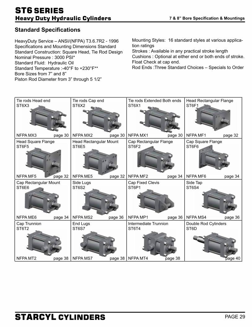
7” & 8” BOREHEAVY DUTY
HIGH PRESSUREHYDRAULIC CYLINDERS
Standard Specifications
HeavyDuty Service – ANSI/(NFPA) T3.6.7R2 - 1996Specifications and Mounting Dimensions StandardStandard Construction: Square Head, Tie Rod DesignNominal Pressure : 3000 PSI*Standard Fluid: Hydraulic OilStandard Temperature :-40°F to +230°F**Bore Sizes from 7” and 8”Piston Rod Diameter from 3” through 5 1/2”
Mounting Styles: 16 standard styles at various applica-tion ratingsStrokes : Available in any practical stroke lengthCushions : Optional at either end or both ends of stroke.Float Check at cap end.Rod Ends :Three Standard Choices – Specials to Order
7 & 8” Bore Specification & Mountings
Tie rods Head endST6X3
NFPA MX3 page 30
Tie rods Cap endST6X2
NFPA MX2 page 30
Tie rods Extended Both endsST6X1
NFPA MX1 page 30
Head Rectangular FlangeST6F1
NFPA MF1 page 32Head Square FlangeST6F5
NFPA MF5 page 32
Head Rectangular MountST6E5
NFPA ME5 page 32
Cap Rectangular FlangeST6F2
NFPA MF2 page 34
Cap Square FlangeST6F6
NFPA MF6 page 34Cap Rectangular MountST6E6
NFPA ME6 page 34
Side LugsST6S2
NFPA MS2 page 36
Cap Fixed ClevisST6P1
NFPA MP1 page 36
Side Tap ST6S4
NFPA MS4 page 36Cap TrunnionST6T2
NFPA MT2 page 38
End LugsST6S7
NFPA MS7 page 38
Intermediate TrunnionST6T4
NFPA MT4 page 38
Double Rod CylindersST6D
page 40
ST6 SERIES Heavy Duty Hydraulic Cylinders
STARCYL CYLINDERS PAGE 29

Tie rod Mountings 7 to 8” Bore Sizes
P + STROKE Y
EE
ROD DIA
DD
MM
EE
BB
KB
ZJ + STROKE
RTGJKWFLB + STROKE
ZB + STROKE
3
1
24 R E
Basic Mounting ST6X0 — NFPA MX0 — no tie rods extended can be supplied upon request.
Tie Rods Extended Head EndStyle ST6X3(NFPA Style MX3)
Tie Rods Extended Cap EndStyle ST6X2(NFPA Style MX2)
Tie Rods Extended Both EndStyle ST6X1(NFPA Style MX1)
P + STROKE Y
3
1
24 R E
EE
ROD DIA
DD
MM
EEKB
ZJ + STROKE
ZB + STROKE
RTGJBBWFLB + STROKE
BB
K
P + STROKE Y
EE
ROD DIA
DD
MM
EEKB
ZJ + STROKE
ZB + STROKE
RTGJ
WF
BBLB + STROKE K
K
3
1
24 R E
WF
RT
LAFWF
RT
LAFWF
RT
A
D WRENCHFLATS
KK
V C
A
BRD
MM
D WRENCHFLATS
CC
V C
A
BRD
MM
FLATSD WRENCH
KK THDA DEEP
V
RD
C
B MM
WF
RT
LAFWF
RT
LAFWF
RT
A
D WRENCHFLATS
KK
V C
A
BRD
MM
D WRENCHFLATS
CC
V C
A
BRD
MM
FLATSD WRENCH
KK THDA DEEP
V
RD
C
B MM
WF
RT
LAFWF
RT
LAFWF
RT
A
D WRENCHFLATS
KK
V C
A
BRD
MM
D WRENCHFLATS
CC
V C
A
BRD
MM
FLATSD WRENCH
KK THDA DEEP
V
RD
C
B MM
ST6 SERIES Heavy Duty Hydraulic Cylinders
STARCYL CYLINDERS
A high strength rod end stud is supplied on thread style #2 through 1” diameter rods and on thread style #1 through 1” diameter rods. Larger sizes or special rod ends are cut threads. Style #2 rod ends are recommended where the workpiece is secured against the rod shoulder. When the workpiece is not shouldered, style 4 rod ends are recommended through 2” piston rod diameters and style #1 rod ends are recommended on larger diameters. Use style #4 for applications where female rod end threads are required. If rod end is not specified, style #2 will be supplied. On 4 1/2” rod and above, 4 .515 spanner Wrench holes will be provided instead of wrench flats
“Specials” Thread Style #XTo order, specify “Style #X” and give desired dimensions for CC or KK, A and LA. If otherwise special, furnish dimensional sketch.
Rod End Dimensions—see table 2Thread Style #2(NFPA Style SM)Small Male
Thread Style #1(NFPA Style IM)Intermediate Male
Thread Style #4(NFPA Style SF)Small Female
PAGE 30

BORE AA BB DD EEE
G J K RADD STROKE
NPTF* SAEstd LB P7 9.3 4 1/8 1 1/8-12 8 1/2 1 1/4 20 2 3/4 2 3/4 1 1/4 6.58 8 1/2 5 1/28 10.6 4 1/2 1 1/4-12 9 1/2 1 1/2 24 3 3 1 1/2 7.50 9 1/2 6 1/4
BORE ROD SIZE
Thread Style Rod Extensions and pilot dimensions
Y
Add StrokeSTYLE
#1CC
STYLE #2 
KK A±.001
B C D KB LAF NA VMAXRD RT WF ZB ZJ
7 std 3 2 3/4-12 2 1/4-12 3 3.748 1 2 5/8 1/4 5 3/4 2 7/8 5/8 5 1/4 5/8 2 1/4 3 3/4 12 10 3/43 1/2 3 1/4-12 2 1/2-12 3 1/2 4.248 1 3 1/4 5 3/4 3 3/8 5/8 5 3/4 5/8 2 1/4 3 3/4 12 10 3/44 3 3/4-12 3-12 4 4.748 1 3 3/8 1/4 6 1/4 3 7/8 1/2 6 1/2 3/4 2 1/4 3 3/4 12 10 3/44 1/2 4 1/4-12 3 1/4-12 4 1/2 5.248 1 - 1/4 6 3/4 4 3/8 1/2 7 3/4 2 1/4 3 3/4 12 10 3/45 4 3/4-12 3 1/2-12 5 5.748 1 - 0 7 1/4 4 7/8 1/4 7 1/4 1 2 1/4 3 3/4 12 10 3/4
8 std 3 1/2 3 1/4-12 2 1/2-12 3 1/2 4.248 1 3 1/4 5 3/4 3 3/8 5/8 5 3/4 5/8 2 1/4 3 7/8 13 1/4 11 3/44 3 3/4-12 3-12 4 4.748 1 3 3/8 1/4 6 1/4 3 7/8 1/2 6 1/2 3/4 2 1/4 3 7/8 13 1/4 11 3/44 1/2 4 1/4-12 3 1/4-12 4 1/2 5.248 1 - 1/4 6 3/4 4 3/8 1/2 7 3/4 2 1/4 3 7/8 13 1/4 11 3/4
5 4 3/4-12 3 1/2-12 5 5.748 1 - 0 7 1/4 4 7/8 1/4 7 1/4 1 2 1/4 3 7/8 13 1/4 11 3/45 1/2 5 1/4-12 4-12 5 1/2 6.248 1 - 0 7 3/4 5 3/8 1/4 8 1/4 1 2 1/4 3 7/8 13 1/4 11 3/4
Tie Rod Mountings 7 to 8” Bore Sizes
Table 1—Envelope and Mounting Dimensions
Table 2—Rod Dimensions
Table 3—Envelope and MountingDimensions
std SAE straight thread ports will be furnished as standard and are indicated by port number.*NPTF ports are available at no extra charge.
ST6 SERIES Heavy Duty Hydraulic Cylinders
STARCYL CYLINDERS PAGE 31

WF
RT
LAFWF
RT
LAFWF
RT
A
D WRENCHFLATS
KK
V C
A
BRD
MM
D WRENCHFLATS
CC
V C
A
BRD
MM
FLATSD WRENCH
KK THDA DEEP
V
RD
C
B MM
WF
RT
LAFWF
RT
LAFWF
RT
A
D WRENCHFLATS
KK
V C
A
BRD
MM
D WRENCHFLATS
CC
V C
A
BRD
MM
FLATSD WRENCH
KK THDA DEEP
V
RD
C
B MM
WF
RT
LAFWF
RT
LAFWF
RT
A
D WRENCHFLATS
KK
V C
A
BRD
MM
D WRENCHFLATS
CC
V C
A
BRD
MM
FLATSD WRENCH
KK THDA DEEP
V
RD
C
B MM
ST6 SERIES Heavy Duty Hydraulic Cylinders
STARCYL CYLINDERS
A high strength rod end stud is supplied on thread style #2 through 1” diameter rods and on thread style #1 through 1” diameter rods. Larger sizes or special rod ends are cut threads. Style #2 rod ends are recommended where the workpiece is secured against the rod shoulder. When the workpiece is not shouldered, style 4 rod ends are recommended through 2” piston rod diameters and style #1 rod ends are recommended on larger diameters. Use style #4 for applications where female rod end threads are required. If rod end is not specified, style #2 will be supplied. On 4 1/2” rod and above, 4 .515 spanner Wrench holes will be provided instead of wrench flats
“Specials” Thread Style #XTo order, specify “Style #X” and give desired dimensions for CC or KK, A and LA. If otherwise special, furnish dimensional sketch.
Rod End Dimensions—see table 2Thread Style #2(NFPA Style SM)Small Male
Thread Style #1(NFPA Style IM)Intermediate Male
Thread Style #4(NFPA Style SF)Small Female
PAGE 32
Rectangular Flangeand Head Mountings
7 to 8” Bore Sizes
P + STROKE Y
EE
ROD DIAMM
EE
F
1/4"
WF
GJK
ZB + STROKE
LB + STROKE
W
3
1
24 E
TF
R
UF
4 HOLESFB
Head Rectangular Flange mountingStyle ST6F1(NFPA Style MF1 )
Head Square Flange mountingStyle ST6F5(NFPA Style MF5)
Head Rectangular mountingStyle ST6E5(NFPA Style ME5)
P + STROKE Y
E
EE
ROD DIAMM
EE
F
1/4"
LB + STROKEGJK
ZB + STROKE
WF
W
3
1
24
R
TFR
TFUF
UF
8 HOLESFB
P + STROKE YEE
ROD DIAMM
EE
RTLB + STROKE
WF
GJK
ZB + STROKE
KB 3
1
24 E
TF
R
UF
4 HOLESFB
* Maximum pressure rating — push application.
*For Pressures exceeding those shown please use mounting style ST6F5 or ST6E5
Bore Size
Max PSI ▬ Push*Rod Size
3 3 1/2 4 4 1/2 5 5 1/27 1500 1250 1000 800 500 -8 - 900 800 700 600 500

ST6 SERIES Heavy Duty Hydraulic Cylinders
STARCYL CYLINDERS PAGE 33
Table 1—Envelope and Mounting Dimensions
Table 2—Rod Dimensions
Table 3—Envelope and Mounting Dimensions
std SAE straight thread ports will be furnished as standard and are indicated by port number.*NPTF ports are available at no extra charge.
Rectangular Flangeand Head Mountings
7 to 8” Bore Sizes
BORE EEE
F FB G J K R TF UFADD STROKE
NPTF* SAEstd LB P7 8 1/2 1 1/4 20 1 1 3/16 2 3/4 2 3/4 1 1/4 6.58 10 5/8 12 5/8 8 1/2 5 1/28 9 1/2 1 1/2 24 1 1 3/16 3 3 1 1/2 7.5 11 13/16 14 9 1/2 6 1/4
BORE ROD SIZE
Thread Style Rod Extensions and pilot dimensions
Y
Add StrokeSTYLE
#1CC
STYLE #2 
KK A±.001
B C D KB LAF NA VMAXRD RT WF ZB
7 std 3 2 3/4-12 2 1/4-12 3 3.748 1 2 5/8 1/4 5 3/4 2 7/8 5/8 5 1/4 5/8 2 1/4 3 3/4 123 1/2 3 1/4-12 2 1/2-12 3 1/2 4.248 1 3 1/4 5 3/4 3 3/8 5/8 5 3/4 5/8 2 1/4 3 3/4 124 3 3/4-12 3-12 4 4.748 1 3 3/8 1/4 6 1/4 3 7/8 1/2 6 1/2 3/4 2 1/4 3 3/4 124 1/2 4 1/4-12 3 1/4-12 4 1/2 5.248 1 - 1/4 6 3/4 4 3/8 1/2 7 3/4 2 1/4 3 3/4 125 4 3/4-12 3 1/2-12 5 5.748 1 - 0 7 1/4 4 7/8 1/4 7 1/4 1 2 1/4 3 3/4 12
8 std 3 1/2 3 1/4-12 2 1/2-12 3 1/2 4.248 1 3 1/4 5 3/4 3 3/8 5/8 5 3/4 5/8 2 1/4 3 7/8 11 3/44 3 3/4-12 3-12 4 4.748 1 3 3/8 1/4 6 1/4 3 7/8 1/2 6 1/2 3/4 2 1/4 3 7/8 11 3/44 1/2 4 1/4-12 3 1/4-12 4 1/2 5.248 1 - 1/4 6 3/4 4 3/8 1/2 7 3/4 2 1/4 3 7/8 11 3/45 4 3/4-12 3 1/2-12 5 5.748 1 - 0 7 1/4 4 7/8 1/4 7 1/4 1 2 1/4 3 7/8 11 3/45 1/2 5 1/4-12 4-12 5 1/2 6.248 1 - 0 7 3/4 5 3/8 1/4 8 1/4 1 2 1/4 3 7/8 11 3/4

WF
RT
LAFWF
RT
LAFWF
RT
A
D WRENCHFLATS
KK
V C
A
BRD
MM
D WRENCHFLATS
CC
V C
A
BRD
MM
FLATSD WRENCH
KK THDA DEEP
V
RD
C
B MM
WF
RT
LAFWF
RT
LAFWF
RT
A
D WRENCHFLATS
KK
V C
A
BRD
MM
D WRENCHFLATS
CC
V C
A
BRD
MM
FLATSD WRENCH
KK THDA DEEP
V
RD
C
B MM
WF
RT
LAFWF
RT
LAFWF
RT
A
D WRENCHFLATS
KK
V C
A
BRD
MM
D WRENCHFLATS
CC
V C
A
BRD
MM
FLATSD WRENCH
KK THDA DEEP
V
RD
C
B MM
ST6 SERIES Heavy Duty Hydraulic Cylinders
STARCYL CYLINDERS
A high strength rod end stud is supplied on thread style #2 through 1” diameter rods and on thread style #1 through 1” diameter rods. Larger sizes or special rod ends are cut threads. Style #2 rod ends are recommended where the workpiece is secured against the rod shoulder. When the workpiece is not shouldered, style 4 rod ends are recommended through 2” piston rod diameters and style #1 rod ends are recommended on larger diameters. Use style #4 for applications where female rod end threads are required. If rod end is not specified, style #2 will be supplied. On 4 1/2” rod and above, 4 .515 spanner Wrench holes will be provided instead of wrench flats
“Specials” Thread Style #XTo order, specify “Style #X” and give desired dimensions for CC or KK, A and LA. If otherwise special, furnish dimensional sketch.
Rod End Dimensions—see table 2Thread Style #2(NFPA Style SM)Small Male
Thread Style #1(NFPA Style IM)Intermediate Male
Thread Style #4(NFPA Style SF)Small Female
PAGE 34
Rectangular Flangeand Cap Mountings
7 to 8” Bore Sizes
P + STROKE Y
E
TF
R
UF
4 HOLESFB EE
ROD DIAMM
EE
LB + STROKE
K
KBGJ
ZF + STROKE
WF
F RT
XF + STROKE
Cap Rectangular Flange mountingStyle ST6F2(NFPA Style MF2 )
Cap Square Flange mountingStyle ST6F6(NFPA Style MF6)
Cap Rectangular mountingStyle ST6E6(NFPA Style ME6)
P + STROKE Y
EE
ROD DIAMM
EE
LB + STROKE
K
KB
GJ
ZF + STROKE
WF
F RT
XF + STROKE
UF
8 HOLESFB
R
TF RE
TF
UF
P + STROKE Y
RE
TFUF
4 HOLESFB
MMROD DIA
EEEE
KBGJ
WF
RTLB + STROKE
K
XF + STROKE
Bore Size
Max PSI ▬ Pull*Rod Size
3 3 1/2 4 4 1/2 5 5 1/27 1500 1700 1800 1900 2000 -8 - 1500 1700 1800 1900 2000
* Maximum pressure rating — pull application.
For Pressures exceeding those shown please use mounting style ST6F6 or ST6E6

ST6 SERIES Heavy Duty Hydraulic Cylinders
STARCYL CYLINDERS PAGE 35
BORE EEE
F FB G J K R TF UFADD STROKE
NPTF* SAEstd LB P7 8 1/2 1 1/4 20 1 1 3/16 2 3/4 2 3/4 1 1/4 6.58 10 5/8 12 5/8 8 1/2 5 1/28 9 1/2 1 1/2 24 1 1 3/16 3 3 1 1/2 7.5 11 13/16 14 9 1/2 6 1/4
Table 1—Envelope and Mounting Dimensions
Table 2—Rod Dimensions
Table 3—Envelope and Mounting Dimensions
std SAE straight thread ports will be furnished as standard and are indicated by port number.*NPTF ports are available at no extra charge.
Rectangular Flangeand Cap Mountings
7 to 8” Bore Sizes
BORE ROD SIZE
Thread Style Rod Extensions and pilot dimensions
Y
Add StrokeSTYLE
#1CC
STYLE #2 
KK A±.001
B C D KB LAF NA VMAXRD RT WF XF ZF
7 std 3 2 3/4-12 2 1/4-12 3 3.748 1 2 5/8 1/4 5 3/4 2 7/8 5/8 5 1/4 5/8 2 1/4 3 3/4 10 3/4 11 3/43 1/2 3 1/4-12 2 1/2-12 3 1/2 4.248 1 3 1/4 5 3/4 3 3/8 5/8 5 3/4 5/8 2 1/4 3 3/4 10 3/4 11 3/44 3 3/4-12 3-12 4 4.748 1 3 3/8 1/4 6 1/4 3 7/8 1/2 6 1/2 3/4 2 1/4 3 3/4 10 3/4 11 3/44 1/2 4 1/4-12 3 1/4-12 4 1/2 5.248 1 - 1/4 6 3/4 4 3/8 1/2 7 3/4 2 1/4 3 3/4 10 3/4 11 3/45 4 3/4-12 3 1/2-12 5 5.748 1 - 0 7 1/4 4 7/8 1/4 7 1/4 1 2 1/4 3 3/4 10 3/4 11 3/4
8 std 3 1/2 3 1/4-12 2 1/2-12 3 1/2 4.248 1 3 1/4 5 3/4 3 3/8 5/8 5 3/4 5/8 2 1/4 3 7/8 11 3/4 12 3/44 3 3/4-12 3-12 4 4.748 1 3 3/8 1/4 6 1/4 3 7/8 1/2 6 1/2 3/4 2 1/4 3 7/8 11 3/4 12 3/44 1/2 4 1/4-12 3 1/4-12 4 1/2 5.248 1 - 1/4 6 3/4 4 3/8 1/2 7 3/4 2 1/4 3 7/8 11 3/4 12 3/45 4 3/4-12 3 1/2-12 5 5.748 1 - 0 7 1/4 4 7/8 1/4 7 1/4 1 2 1/4 3 7/8 11 3/4 12 3/45 1/2 5 1/4-12 4-12 5 1/2 6.248 1 - 0 7 3/4 5 3/8 1/4 8 1/4 1 2 1/4 3 7/8 11 3/4 12 3/4

WF
RT
LAFWF
RT
LAFWF
RT
A
D WRENCHFLATS
KK
V C
A
BRD
MM
D WRENCHFLATS
CC
V C
A
BRD
MM
FLATSD WRENCH
KK THDA DEEP
V
RD
C
B MM
WF
RT
LAFWF
RT
LAFWF
RT
A
D WRENCHFLATS
KK
V C
A
BRD
MM
D WRENCHFLATS
CC
V C
A
BRD
MM
FLATSD WRENCH
KK THDA DEEP
V
RD
C
B MM
WF
RT
LAFWF
RT
LAFWF
RT
A
D WRENCHFLATS
KK
V C
A
BRD
MM
D WRENCHFLATS
CC
V C
A
BRD
MM
FLATSD WRENCH
KK THDA DEEP
V
RD
C
B MM
ST6 SERIES Heavy Duty Hydraulic Cylinders
STARCYL CYLINDERS
A high strength rod end stud is supplied on thread style #2 through 1” diameter rods and on thread style #1 through 1” diameter rods. Larger sizes or special rod ends are cut threads. Style #2 rod ends are recommended where the workpiece is secured against the rod shoulder. When the workpiece is not shouldered, style 4 rod ends are recommended through 2” piston rod diameters and style #1 rod ends are recommended on larger diameters. Use style #4 for applications where female rod end threads are required. If rod end is not specified, style #2 will be supplied. On 4 1/2” rod and above, 4 .515 spanner Wrench holes will be provided instead of wrench flats
“Specials” Thread Style #XTo order, specify “Style #X” and give desired dimensions for CC or KK, A and LA. If otherwise special, furnish dimensional sketch.
Rod End Dimensions—see table 2Thread Style #2(NFPA Style SM)Small Male
Thread Style #1(NFPA Style IM)Intermediate Male
Thread Style #4(NFPA Style SF)Small Female
PAGE 36
Side Lugs, Side Tapped Mountings& Cap Fixed Clevis7 to 8” Bore Sizes
SWSW SW
TSSW
E/2
P + STROKE
XS
Y
SWSUSW SU
SS + STROKE
4
1
2
3
SB4 HOLES
ST
E
US
EE
ROD DIAMM
EE
WF
ZB + STROKE
RTGJK
KBLB + STROKE
Side Lugs mountingStyle ST6S2(NFPA Style MS2 )
Side Tapped mountingStyle ST6S4(NFPA Style MS4)
P + STROKE
XT
Y
SN + STROKE
TN
E/2
EE
ROD DIAMM
EE
WF
ZB + STROKE
RTGJK
KBLB + STROKE
4
1
2
3
NT THREAD, ND DEEP4 TAPPED MTG. HOLES
E
Cap Fixed Clevis mountingStyle ST6P1(NFPA Style MP1)
MR
P + STROKE Y
LR
EE
ROD DIAMM
EE
PINCD
LB + STROKE
GM
J RT
K
KB
WF
XC + STROKE
ZC + STROKE
CW CB CW
E
refer table 1b and 2b for dimensions

ST6 SERIES Heavy Duty Hydraulic Cylinders
STARCYL CYLINDERS PAGE 37
Side Lugs, Side Tapped Mountings& Cap Fixed Clevis7 to 8” Bore Sizes
Table 1a—Envelope and Mounting Dimensions
Table 2a—Rod Dimensions
std SAE straight thread ports will be furnished as standard and are indicated by port number.*NPTF ports are available at no extra charge.1 Upper suface spotfaced for S.H.C.S.
BORE EEE
G J K NT SB1 ST SU SW TN TS USADD STROKE
NPTF* SAEstd LB P SN SS7 8 1/2 1 1/4 20 2 3/4 2 3/4 1 1/4 1 1/2-6 1 9/16 1 3/4 2 7/8 1 3/8 3 3/4 11 1/4 14 8 1/2 5 1/2 5 7/8 5 3/48 9 1/2 1 1/2 24 3 3 1 1/2 1 1/2-6 1 9/16 1 3/4 2 7/8 1 3/8 4 1/4 12 1/4 25 9 1/2 6 1/4 6 5/8 6 3/4
BORE ROD SIZE
Thread Style Rod Extensions and pilot dimensions
Y ND XS XT
Add Stroke
STYLE #1CC
STYLE #2 
KK A±.001
B C D KB LAF NA VMAXRD RT WF ZB
7 std 3 2 3/4-12 2 1/4-12 3 3.748 1 2 5/8 1/4 5 3/4 2 7/8 5/8 5 1/4 5/8 2 1/4 3 13/16 123 1/2 3 1/4-12 2 1/2-12 3 1/2 4.248 1 3 1/4 5 3/4 3 3/8 5/8 5 3/4 5/8 2 1/4 3 3/4 1 1/8 3 5/8 3 13/16 124 3 3/4-12 3-12 4 4.748 1 3 3/8 1/4 6 1/4 3 7/8 1/2 6 1/2 3/4 2 1/4 3 3/4 1 1/8 3 5/8 3 13/16 124 1/2 4 1/4-12 3 1/4-12 4 1/2 5.248 1 - 1/4 6 3/4 4 3/8 1/2 7 3/4 2 1/4 3 3/4 1 1/8 3 5/8 3 13/16 125 4 3/4-12 3 1/2-12 5 5.748 1 - 0 7 1/4 4 7/8 1/4 7 1/4 1 2 1/4 3 3/4 1 1/8 3 5/8 3 13/16 12
8 std 3 1/2 3 1/4-12 2 1/2-12 3 1/2 4.248 1 3 1/4 5 3/4 3 3/8 5/8 5 3/4 5/8 2 1/4 3 3/4 1 1/8 3 5/8 3 15/16 11 3/44 3 3/4-12 3-12 4 4.748 1 3 3/8 1/4 6 1/4 3 7/8 1/2 6 1/2 3/4 2 1/4 3 7/8 1 1/8 3 5/8 3 15/16 11 3/44 1/2 4 1/4-12 3 1/4-12 4 1/2 5.248 1 - 1/4 6 3/4 4 3/8 1/2 7 3/4 2 1/4 3 7/8 1 1/8 3 5/8 3 15/16 11 3/45 4 3/4-12 3 1/2-12 5 5.748 1 - 0 7 1/4 4 7/8 1/4 7 1/4 1 2 1/4 3 7/8 1 1/8 3 5/8 3 15/16 11 3/45 1/2 5 1/4-12 4-12 5 1/2 6.248 1 - 0 7 3/4 5 3/8 1/4 8 1/4 1 2 1/4 3 7/8 1 1/8 3 5/8 3 15/16 11 3/4
BORE CB
+.000-.002CD* CW E
EE
G J K L LR M MR
ADD STROKE
NPTF* SAEstd LB P7 3 2.501 1 1/2 8 1/2 1 1/4 20 2 3/4 2 3/4 1 1/4 3 2 3/4 2 1/2 2 7/8 8 1/2 5 1/28 3 3.001 1 1/2 9 1/2 1 1/2 24 3 3 1 1/2 3 1/4 3 1/4 2 3/4 3 1/8 9 1/2 6 1/4
Table 1b—Envelope and Mounting Dimensions
Table 2b—Rod Dimensions
Table 3b—Envelope and Mounting Dimensions
BORE ROD SIZE
Thread Style Rod Extensions and pilot dimensions
Y
Add Stroke
STYLE #1
STYLE #2 
KK A±.001
B C D KB LAF NA VMAXRD RT WF XC ZC
7 std 3 2 3/4-12 2 1/4-12 3 3.748 1 2 5/8 1/4 5 3/4 2 7/8 5/8 5 1/4 5/8 2 1/4 3 3/4 13 3/4 16 1/43 1/2 3 1/4-12 2 1/2-12 3 1/2 4.248 1 3 1/4 5 3/4 3 3/8 5/8 5 3/4 5/8 2 1/4 3 3/4 13 3/4 16 1/44 3 3/4-12 3-12 4 4.748 1 3 3/8 1/4 6 1/4 3 7/8 1/2 6 1/2 3/4 2 1/4 3 3/4 13 3/4 16 1/44 1/2 4 1/4-12 3 1/4-12 4 1/2 5.248 1 - 1/4 6 3/4 4 3/8 1/2 7 3/4 2 1/4 3 3/4 13 3/4 16 1/45 4 3/4-12 3 1/2-12 5 5.748 1 - 0 7 1/4 4 7/8 1/4 7 1/4 1 2 1/4 3 3/4 13 3/4 16 1/4
8 std 3 1/2 3 1/4-12 2 1/2-12 3 1/2 4.248 1 3 1/4 5 3/4 3 3/8 5/8 5 3/4 5/8 2 1/4 3 3/4 3 7/8 17 3/44 3 3/4-12 3-12 4 4.748 1 3 3/8 1/4 6 1/4 3 7/8 1/2 6 1/2 3/4 2 1/4 3 7/8 3 7/8 17 3/7 4 1/2 4 1/4-12 3 1/4-12 4 1/2 5.248 1 - 1/4 6 3/4 4 3/8 1/2 7 3/4 2 1/4 3 7/8 3 7/8 17 3/7 5 4 3/4-12 3 1/2-12 5 5.748 1 - 0 7 1/4 4 7/8 1/4 7 1/4 1 2 1/4 3 7/8 3 7/8 17 3/7 5 1/2 5 1/4-12 4-12 5 1/2 6.248 1 - 0 7 3/4 5 3/8 1/4 8 1/4 1 2 1/4 3 7/8 3 7/8 17 3/7
Table 3a—Envelope and Mounting Dimensions

WF
RT
LAFWF
RT
LAFWF
RT
A
D WRENCHFLATS
KK
V C
A
BRD
MM
D WRENCHFLATS
CC
V C
A
BRD
MM
FLATSD WRENCH
KK THDA DEEP
V
RD
C
B MM
WF
RT
LAFWF
RT
LAFWF
RT
A
D WRENCHFLATS
KK
V C
A
BRD
MM
D WRENCHFLATS
CC
V C
A
BRD
MM
FLATSD WRENCH
KK THDA DEEP
V
RD
C
B MM
WF
RT
LAFWF
RT
LAFWF
RT
A
D WRENCHFLATS
KK
V C
A
BRD
MM
D WRENCHFLATS
CC
V C
A
BRD
MM
FLATSD WRENCH
KK THDA DEEP
V
RD
C
B MM
ST6 SERIES Heavy Duty Hydraulic Cylinders
STARCYL CYLINDERS
A high strength rod end stud is supplied on thread style #2 through 1” diameter rods and on thread style #1 through 1” diameter rods. Larger sizes or special rod ends are cut threads. Style #2 rod ends are recommended where the workpiece is secured against the rod shoulder. When the workpiece is not shouldered, style 4 rod ends are recommended through 2” piston rod diameters and style #1 rod ends are recommended on larger diameters. Use style #4 for applications where female rod end threads are required. If rod end is not specified, style #2 will be supplied. On 4 1/2” rod and above, 4 .515 spanner Wrench holes will be provided instead of wrench flats
“Specials” Thread Style #XTo order, specify “Style #X” and give desired dimensions for CC or KK, A and LA. If otherwise special, furnish dimensional sketch.
Rod End Dimensions—see table 2Thread Style #2(NFPA Style SM)Small Male
Thread Style #1(NFPA Style IM)Intermediate Male
Thread Style #4(NFPA Style SF)Small Female
PAGE 38
Trunnion Mountings 7 to 8” Bore Sizes
Head TrunnionStyle ST6T1(NFPA Style MT1)
Cap TrunnionStyle ST6T2(NFPA Style MT2)
Intermediate Fixed TrunnionStyle ST6T4(NFPA Style MT4)
**Dimension XI to be specified by customer.
P + STROKE Y
MMROD DIA
EEEELB + STROKE
RTGJK
KBWF
ZB + STROKE
XG
1
2
3
4
TL
ETD
1/8" R
TLUT
P + STROKE Y
3
1
24
TD
1/8" R
TL TL
E
UT
EE
ROD DIAMM
EE
ZB + STROKE
LB + STROKE
RTG
KB
JK
WF
XJ + STROKE
P + STROKE Y
EE
ROD DIAMM
EE
LB + STROKE
BD
WFRTGJK
WF
ZB + STROKE
KB
Xi
3
1
24
TL TM
ETD
TL
UW
UM

ST6 SERIES Heavy Duty Hydraulic Cylinders
STARCYL CYLINDERS PAGE 39
Trunnion Mountings 7 to 8” Bore Sizes
Table 1—Envelope and Mounting Dimensions
Table 2—Rod DimensionsTable 3—Envelope and Mounting Dimensions
**Dimension XI to be specified by customer.
std SAE straight thread ports will be furnished as standard and are indicated by port number.*NPTF ports are available at no extra charge.
BORE BD E
EE
F G J K
+.000-.002TD TL TM UM UT UW
ADD STROKE Style DDMinimum
StrokeNPTF* SAEstd LB P7 3 8 1/2 1 1/4 20 1 2 3/4 2 3/4 1 1/4 2.500 2 1/2 9 3/4 14 3/4 13 1/2 11 1/2 8 1/2 5 1/2 1/8”8 3 1/2 9 1/2 1 1/2 24 1 3 3 1 1/2 3.000 3 11 17 15 1/2 13 3/8 9 1/2 6 1/4 1/8”
BORE ROD SIZE
Thread Style Rod Extensions and pilot dimensions
XG
MIN.Xi Y
Add StrokeSTYLE
#1CC
STYLE #2 
KK A±.001
B C D KB LAF NA VMAXRD RT WF XJ ZB
7 std 3 2 3/4-12 2 1/4-12 3 1/2 3.748 1 2 5/8 1/4 5 3/4 2 7/8 5/8 5 1/4 5/8 2 1/4 3 5/8 6 9/16 3 3/4 9 3/8 123 1/2 3 1/4-12 2 1/2-12 3 1/2 4.248 1 3 1/4 5 3/4 3 3/8 5/8 5 3/4 5/8 2 1/4 3 5/8 6 9/16 3 3/4 9 3/8 124 3 3/4-12 3-12 4 4.748 1 3 3/8 1/4 6 1/4 3 7/8 1/2 6 1/2 3/4 2 1/4 3 5/8 6 9/16 3 3/4 9 3/8 124 1/2 4 1/4-12 3 1/4-12 4 1/2 5.248 1 - 1/4 6 3/4 4 3/8 1/2 7 3/4 2 1/4 3 5/8 6 9/16 3 3/4 9 3/8 125 4 3/4-12 3 1/2-12 5 5.748 1 - 0 7 1/4 4 7/8 1/4 7 1/4 1 2 1/4 3 5/8 6 9/16 3 3/4 9 3/8 12
8 std 3 1/2 3 1/4-12 2 1/2-12 3 1/2 4.248 1 3 1/4 5 3/4 3 3/8 5/8 5 3/4 5/8 2 1/4 3 3/4 7 1/16 3 7/8 10 1/4 13 1/44 3 3/4-12 3-12 4 4.748 1 3 3/8 1/4 6 1/4 3 7/8 1/2 6 1/2 3/4 2 1/4 3 3/4 7 1/16 3 7/8 10 1/4 13 1/44 1/2 4 1/4-12 3 1/4-12 4 1/2 5.248 1 - 1/4 6 3/4 4 3/8 1/2 7 3/4 2 1/4 3 3/4 7 1/16 3 7/8 10 1/4 13 1/45 4 3/4-12 3 1/2-12 5 5.748 1 - 0 7 1/4 4 7/8 1/4 7 1/4 1 2 1/4 3 3/4 7 1/16 3 7/8 10 1/4 13 1/45 1/2 5 1/4-12 4-12 5 1/2 6.248 1 - 0 7 3/4 5 3/8 1/4 8 1/4 1 2 1/4 3 3/4 7 1/16 3 7/8 10 1/4 13 1/4

ST6 SERIES Heavy Duty Hydraulic Cylinders
STARCYL CYLINDERS PAGE 40
Double Rod endStyle ST6D
BOREROD SIZE
Add Stroke Add 2X Stroke
LD ZL SSD SND ZM7 std 3 8 1/2 11 3/4 5 3/4 5 3/8 138 std 3 1/2 9 1/2 12 13/16 6 3/4 6 1/8 14
Replaces : LB ZB SS SN --On single rod mounting
styles:All Mtgs. Style MS2 MS4 All Mtgs.
To determine dimensions for a double rod cylinder, first refer to the desired single rod mounting style cylinder shown on preceding pages of this catalog. After selecting necessary dimensions from that drawing, return to this page supplement the single rod dimensions with those shown on drawings above and dimen-sion table below. Note that double rod cylinders have a head (Dim. G) at both ends and that dimension LD replaces LB and ZL replaces ZB, etc. The double rod dimensions differ from, or are in addition to those for single rod cylinders shown on preceding pages and provide the information needed to completely dimen-sion a double rod cylinder. On a double rod cylinder where the two rod ends are different, be sure to clearly state which rod end is to be assembled at which end. Port position 1 is standard. If other than standard, specify pos. 2, 3 or 4 when viewed from rod end No1 only. (See port position information in Page 29.)
All dimensions are in inches and apply to standard rod sizes only.For alternate rod sizes, determine all envelope dimensions (within LD dim.) as described above and then use appropriate rod end dimensions for proper rod size from single rod cylinder.
P + STROKE Y
EE
MM ROD DIA
EE
GRTLD + STROKE WF
KKB
ZL + STROKE
KBRTG
ZM + 2 x STROKE
Double Rod End and1 1/2 to 6” Bore Sizes
Rod End No1Rod End No2
Standard Cushion position for double rod will be 2 and 4 looking at cylinder from Rod End #1

Notes:
ST6 SERIES Heavy Duty Hydraulic Cylinders
STARCYL CYLINDERS PAGE 41

LARGE BOREHIGH PRESSURE
HYDRAULIC CYLINDERS
ST6 SERIES Heavy Duty Hydraulic Cylinders
STARCYL CYLINDERS PAGE 42

Standard Specifications
HeavyDuty Service –Specifications and Mounting Dimensions StandardStandard Construction: Square Head, Tie Rod DesignNominal Pressure : 3000 PSI*Standard Fluid: Hydraulic OilStandard Temperature :-40°F to +230°F**Bore Sizes from 10” throught 20”Piston Rod Diameter from 4 1/2” through 10”
Mounting Styles: 10 standard styles at various applica-tion ratingsStrokes : Available in any practical stroke lengthCushions : Optional at either end or both ends of stroke.Float Check at cap end.Rod Ends :Two Standard Choices – Specials to Order
Large Bore Specification & Mountings
Tie rods Head endST6X3
NFPA MX3 page 44
Tie rods Cap endST6X2
NFPA MX2 page 44
Tie rods Extended Both endsST6X1
NFPA MX1 page 44
Head RectangularST6E5
NFPA ME5 page 46Head Square FlangeST6F5
NFPA MF5 page 46
Cap Rectangular MountST6E6
NFPA ME6 page 48
Cap Square FlangeST6F6
NFPA MF6 page 48
Side LugsST6S2
NFPA MS2 page 50Center LugsST6S3
NFPA MS2 page 50
Cap Fixed ClevisST6P1
NFPA MP1 page 50
Head TrunnionST6T1
NFPA MT1 page 52
Cap TrunnionST6T2
NFPA MT2 page 52Intermediate TrunnionST6T4
NFPA MT4 page 52
Double Rod CylindersST6D
page 54
ST6 SERIES Heavy Duty Hydraulic Cylinders
STARCYL CYLINDERS PAGE 43

Tie rod Mountings Large Bore Sizes
P + STROKE Y
EEDD
EE
MMROD DIA
K
GJWFLB + STROKE
ZJ + STROKE
ZB + STROKE
F
BB
RD
3
1
24 E
E
Basic Mounting ST6X0 — NFPA MX0 — no tie rods extended can be supplied upon request.
Tie Rods Extended Head EndStyle ST6X3(NFPA Style MX3)
Tie Rods Extended Cap EndStyle ST6X2(NFPA Style MX2)
Tie Rods Extended Both EndStyle ST6X1(NFPA Style MX1)
P + STROKE Y
3
1
24 E
E
ROD DIA
EEEE
MMDD
BBGJ
WFLB + STROKE
ZJ + STROKE
ZB + STROKE
K
F
RD
P + STROKE Y
EE
ROD DIA
DD
MM
EE
GBB
JLB + STROKE
ZJ + STROKE
F
ZB + STROKE
K
WFBB
RD
2
3
1
4 E
E
KK
MM ROD
NA.516
x .750 DP.4 HOLES
RD
C
F
WF A
LAF
KK
MM ROD
NA.516
x .500 DP.4 HOLES
RD
C
F
WFA
ST6 SERIES - Large Bore Heavy Duty Hydraulic Cylinders
STARCYL CYLINDERS
“Specials” Thread Style #XTo order, specify “Style #X” and give desired dimensions for CC or KK, A and LA. If otherwise spe-cial, furnish dimen-sional sketch.
Rod End Dimensions—see table 2
Thread Style #2(NFPA Style SM)Small Male
Thread Style #4(NFPA Style SF)Small Female
PAGE 44
KK
MM ROD
NA.516
x .750 DP.4 HOLES
RD
C
F
WF A
LAF
KK
MM ROD
NA.516
x .500 DP.4 HOLES
RD
C
F
WFA

BORE BB DD E
EE
G J K
ADD STROKENPTF** SAE
flange port
SAEstd
Straight Thread
LB P
10 4 1/8 1 1/8-12 12 5/8 2 2 24 3 11/16 3 11/16 1 9/32 12 1/8 8 1/212 4 1/2 1 1/4-12 14 7/8 2 1/2 2 1/2 24 4 7/16 4 7/16 1 13/32 14 1/2 10 1/814 4 1/2 1 1/4-12 17 1/8 2 1/2 2 1/2 24 4 7/8 4 7/8 1 13/32 15 5/8 10 7/8
BORE ROD SIZE
Thread Rod Extensions and pilot dimensions
Y
Add StrokeSTYLE #2 
KK A
+.000 -.005
B C F LAF NA RR V WF ZB ZJ10 std 4 1/2 3 1/4-12 4 1/2 5.249 1 1 15/16 7 7/16 4 3/8 2 1/8 1//4 2 15/16 4 3/4 16 11/32 15 1/16
5 3 1/2-12 5 5.749 1 1 15/16 8 3/16 4 7/8 1/4 3 3/16 5 16 19/32 15 5/165 1/2 4-12 5 1/2 6.249 1 1 15/16 8 11/16 5 3/8 1/4 3 3/16 5 16 19/32 15 5/167 5-12 7 7.999 1 1 15/16 10 1/2 6 7/8 3/8 3 1/2 5 5/16 16 29/32 15 5/8
12 std 5 1/2 4-12 5 1/2 6.249 1 1 15/16 8 11/16 5 3/8 2 3/8 1/4 3 3/16 5 3/8 19 3/32 17 11/167 5-12 7 7.999 1 1 15/16 10 1/2 6 7/8 3/8 3 1/2 5 11/16 19 13/32 188 5 3/4-12 8 8.999 1 1 15/16 12 7 7/8 3/8 4 6 3/16 19 29.32 18 1/2
14 std 7 5-12 7 7.999 1 1 15/16 10 1/2 6 7/8 2 3/8 3/8 3 1/2 5 7/8 20 17/32 19 1/88 5 3/4-12 8 8.999 1 1 15/16 12 7 7/8 3/8 4 6 3/8 21 1/32 19 5/810 7 1/4-12 10 10.999 1 1 15/16 14 1/2 9 7/8 3/8 4 1/2 6 7/8 21 17/32 20 1/8
Tie Rod Mountings Large Bore Sizes
Table 1—Envelope and Mounting Dimensions
Table 2—Rod Dimensions
Table 3—Envelope and MountingDimensions
std SAE straight thread ports will be furnished as standard and are indicated by port number.* Optional SAE Flange ports may be specified - flange to be supplied by customer. see Table 4 for flange port patern dimensions**NPTF ports are available at extra charge.
ST6 SERIES Heavy Duty Hydraulic Cylinders
STARCYL CYLINDERS PAGE 45
Nom. Flange
Size A Q GG W X
ZThread UNC 2B
AA min. SAE
1 1/2 1.50 2.750 1.406 1.38 0.70 1/2-13 1.06 242 2.00 3.062 1.688 1.53 0.84 1/2-13 1.06 32
2 1/2 2.50 3.500 2.000 1.75 1.00 1/2-13 1.19 403 3.00 4.188 2.438 2.09 1.22 5/8-11 1.19 48 BORE 10 12 14 16 18 20
Tie rod Thread 1 1/8-12 1 1/4-12 1 1/4-12 1 1/2-12 1 1/2-12 1 1/2-12RA 5.291 6.270 7.485 8.086 9.589 10.437RB 3.775 4.555 6.143 6.093 7.910 8.750RC - - 4.409 - 5.761 6.649
Table 4— Optional SAEFlange port patern
Table 5— Tie Rod Info.
W
xGG
Q
A DIA
HEADOR CAP
Z - 4 HOLESAA MIN. THREAD DEPTH.
RC
RB
RBRA
RC
RA
RB R
A
RBRA
10”, 12”, 16 bore 14”, 18”, 20” bore
RR dia

KK
MM ROD
NA.516
x .750 DP.4 HOLES
RD
C
F
WF A
LAF
KK
MM ROD
NA.516
x .500 DP.4 HOLES
RD
C
F
WFA
ST6 SERIES - Large Bore Heavy Duty Hydraulic Cylinders
STARCYL CYLINDERS
“Specials” Thread Style #XTo order, specify “Style #X” and give desired dimensions for CC or KK, A and LA. If otherwise spe-cial, furnish dimen-sional sketch.
Rod End Dimensions—see table 2
Thread Style #2(NFPA Style SM)Small Male
Thread Style #4(NFPA Style SF)Small Female
PAGE 46
KK
MM ROD
NA.516
x .750 DP.4 HOLES
RD
C
F
WF A
LAF
KK
MM ROD
NA.516
x .500 DP.4 HOLES
RD
C
F
WFA
Head Rectangular Flangeand Square Mountings
Large Bore Sizes
P + STROKE Y
E
EE
ROD DIAMM
EE
RD
G F
ZB + STROKE
LB + STROKEJ
WF
K
4
1
2
3
FB4 HOLES
TF
R E
UF
Head Rectangular Mounting (10”-14” Bore)Style ST6E5(NFPA Style ME5 )
Head Rectangular Mounting (16”-20” Bore)Style ST6E5(NFPA Style ME5)
Head Square Flange MountingStyle ST6F5(NFPA Style MF5)
P + STROKE Y
E
E
MMROD DIA
EEEE
GJ
ZB + STROKE
LB + STROKE
RD
WFF
K
A
1
2
3
4
FB8 HOLES
R
TFUF
EJRA
EE
P + STROKE Y
3
4
1
2
EB8 HOLES
TEEX
RE
EX
RE
TE
ROD DIA
EE
MMEE
FWF
GJ
ZB + STROKE
LB + STROKEK
RD

ST6 SERIES Heavy Duty Hydraulic Cylinders
STARCYL CYLINDERS PAGE 47
Nom. Flange
Size A Q GG W X
ZThread UNC 2B
AA min. SAE
1 1/2 1.50 2.750 1.406 1.38 0.70 1/2-13 1.06 242 2.00 3.062 1.688 1.53 0.84 1/2-13 1.06 32
2 1/2 2.50 3.500 2.000 1.75 1.00 1/2-13 1.19 403 3.00 4.188 2.438 2.09 1.22 5/8-11 1.19 48 BORE 10 12 14 16 18 20
Tie rod Thread 1 1/8-12 1 1/4-12 1 1/4-12 1 1/2-12 1 1/2-12 1 1/2-12RA 5.291 6.270 7.485 8.086 9.589 10.437RB 3.775 4.555 6.143 6.093 7.910 8.750RC - - 4.409 - 5.761 6.649
Table 4— Optional SAEFlange port patern
Table 5— Tie Rod Info.
W
xGG
Q
A DIA
HEADOR CAP
Z - 4 HOLESAA MIN. THREAD DEPTH.
RC
RB
RBRA
RC
RA
RB R
A
RBRA
10”, 12”, 16 bore 14”, 18”, 20” bore
Head Rectangular Flangeand Square Mountings
Large Bore Sizes
BORE E EB
EE
EX FB G J K R RE TE TF UF
ADD STROKENPTF** SAE
flange port
SAEstd
Straight Thread
LB P
10 12 5/8 1 5/16 2 2 24 16 5/8 1 13/16 3 11/16 3 11/16 1 9/32 9.62 9.89 14.13 15 7/8 19 12 1/8 8 1/212 14 7/8 1 9/16 2 1/2 2 1/2 24 19 3/4 2 1/16 4 7/16 4 7/16 1 13/32 11.45 11.75 16.79 18 1/2 22 14 1/2 10 1/814 17 1/8 1 13/16 2 1/2 2 1/2 24 21 3/4 2 5/16 4 7/8 4 7/8 1 13/32 13.26 12.90 18.43 21 25 15 5/8 10 7/8
BORE ROD SIZE
Thread Rod Extensions and pilot dimensions
Y
Add Stroke
STYLE #2 
KK A
+.000 -.005
B C F LAF NA RD V WF ZB10 std 4 1/2 3 1/4-12 4 1/2 5.249 1 1 15/16 7 7/16 4 3/8 8 1/4 1/4 2 15/16 4 3/4 16 11/32
5 3 1/2-12 5 5.749 1 1 15/16 8 3/16 4 7/8 8 7/8 1/4 3 3/16 5 16 19/325 1/2 4-12 5 1/2 6.249 1 1 15/16 8 11/16 5 3/8 9 3/8 1/4 3 3/16 5 16 19/32
7 5-12 7 7.999 1 1 15/16 10 1/2 6 7/8 10 1/2 3/8 3 1/2 5 5/16 16 29/32
12 std 5 1/2 4-12 5 1/2 6.249 1 1 15/16 8 11/16 5 3/8 9 3/8 1/4 3 3/16 5 3/8 19 3/327 5-12 7 7.999 1 1 15/16 10 1/2 6 7/8 10 1/2 3/8 3 1/2 5 11/16 19 13/328 5 3/4-12 8 8.999 1 1 15/16 12 7 7/8 12 1/2 3/8 4 6 3/16 19 29.32
14 std 7 5-12 7 7.999 1 1 15/16 10 1/2 6 7/8 10 1/2 3/8 3 1/2 5 7/8 20 17/328 5 3/4-12 8 8.999 1 1 15/16 12 7 7/8 12 1/2 3/8 4 6 3/8 21 1/32
10 7 1/4-12 10 10.999 1 1 15/16 14 1/2 9 7/8 14 1/2 3/8 4 1/2 6 7/8 21 17/32
16 std 8 5 3/4-12 8 8.999 1 1 15/16 12 7 7/8 12 1/2 3/8 4 7 24 1/329 6 1/2-12 9 9.999 1 1 15/16 13 1/4 8 7/8 13 1/2 3/8 4 1/4 7 1/4 24 9/32
10 7 1/4-12 10 10.999 1 1 15/16 14 1/2 9 7/8 14 1/2 3/8 4 1/2 7 1/2 24 17/32
18 std 9 6 1/2-12 9 9.999 1 1 15/16 13 1/4 8 7/8 13 1/2 3/8 4 1/4 7 1/4 27 9/3210 7 1/4-12 10 10.999 1 1 15/16 14 1/2 9 7/8 14 1/2 3/8 4 1/2 7 1/2 27 17/32
20 std 10 7 1/4-12 10 10.999 1 1 15/16 14 1/2 9 7/8 14 1/2 3/8 4 1/2 7 1/2 30 1/32
Table 1—Envelope and Mounting Dimensions
Table 2—Rod Dimensions Table 3— Envelope and Mounting Dimensions
std SAE straight thread ports will be furnished as standard and are indicated by port number.* Optional SAE Flange ports may be specified - flange to be supplied by customer. see Table 4 for flange port patern dimensions**NPTF ports are available at extra charge.
BORE E EB
EE
EX EJ FB G J K R RA RE TE TF UF
ADD STROKENPTF
**SAE flange port
SAEstd
Straight Thread
LB P
16 19 1 13/16 2 1/2 24 3 24 1/2 20 1 13/16 5 7/8 5 7/8 1 29/32 15 1/2 8 15.28 21.03 21 24 1/2 18 1/8 12 1/818 22 2 1/16 2 1/2 24 3 26 1/2 23 2 1/16 6 7/8 6 7/8 1 29/32 18 7 1/4 16.45 22.65 24 1/4 28 1/4 21 1/8 15 1/820 24 2 1/16 2 1/2 24 3 29 25 2 1/16 7 7/8 7 7/8 1 29/32 20 8 18.07 24.87 16 1/2 26 1/2 23 5/8 17 5/8
Table 1A—Envelope and Mounting Dimensions

KK
MM ROD
NA.516
x .750 DP.4 HOLES
RD
C
F
WF A
LAF
KK
MM ROD
NA.516
x .500 DP.4 HOLES
RD
C
F
WFA
ST6 SERIES - Large Bore Heavy Duty Hydraulic Cylinders
STARCYL CYLINDERS
“Specials” Thread Style #XTo order, specify “Style #X” and give desired dimensions for CC or KK, A and LA. If otherwise spe-cial, furnish dimen-sional sketch.
Rod End Dimensions—see table 2
Thread Style #2(NFPA Style SM)Small Male
Thread Style #4(NFPA Style SF)Small Female
PAGE 48
KK
MM ROD
NA.516
x .750 DP.4 HOLES
RD
C
F
WF A
LAF
KK
MM ROD
NA.516
x .500 DP.4 HOLES
RD
C
F
WFA
Rectangular Flangeand Cap Mountings
Large Bore Sizes
E
P + STROKE Y
1
4
3
2
TF
R E
UF
FB4 HOLES EE
ROD DIAMM
EE
WFG
K
XF + STROKE
RD
LB + STROKEJ F
Cap Rectangular Mounting (10”-14” Bore)Style ST6E6(NFPA Style ME6 )
Cap Rectangular Mounting (16”-20” Bore)Style ST6E6(NFPA Style ME6)
Cap Square Flange MountingStyle ST6F6(NFPA Style MF6)
P + STROKE Y
E
E
EE
ROD DIAMM
EE
RD
GJWFLB + STROKE
K
XF + STROKE
F
1
3
4
FB8 HOLES
2
UF
R EJ
TF
RA
P + STROKE
E
E
3
1
24
TE
RE TE EX
8 HOLESEB
RE
EX
EE
ROD DIAMM
EEY
GJLB + STROKE
XF + STROKE
FWF
K
RD

ST6 SERIES Heavy Duty Hydraulic Cylinders
STARCYL CYLINDERS PAGE 49
Nom. Flange
Size A Q GG W X
ZThread UNC 2B
AA min. SAE
1 1/2 1.50 2.750 1.406 1.38 0.70 1/2-13 1.06 242 2.00 3.062 1.688 1.53 0.84 1/2-13 1.06 32
2 1/2 2.50 3.500 2.000 1.75 1.00 1/2-13 1.19 403 3.00 4.188 2.438 2.09 1.22 5/8-11 1.19 48 BORE 10 12 14 16 18 20
Tie rod Thread 1 1/8-12 1 1/4-12 1 1/4-12 1 1/2-12 1 1/2-12 1 1/2-12RA 5.291 6.270 7.485 8.086 9.589 10.437RB 3.775 4.555 6.143 6.093 7.910 8.750RC - - 4.409 - 5.761 6.649
Table 4— Optional SAEFlange port patern
Table 5— Tie Rod Info.
W
xGG
Q
A DIA
HEADOR CAP
Z - 4 HOLESAA MIN. THREAD DEPTH.
RC
RB
RBRA
RC
RA
RB R
A
RBRA
10”, 12”, 16 bore 14”, 18”, 20” bore
Rectangular Flangeand Cap Mountings
Large Bore Sizes
BORE E EB
EE
EX FB G J K R RE TE TF UF
ADD STROKENPTF** SAE
flange port
SAEstd
Straight Thread
LB P
10 12 5/8 1 5/16 2 2 24 16 5/8 1 13/16 3 11/16 3 11/16 1 9/32 9.62 9.89 14.13 15 7/8 19 12 1/8 8 1/212 14 7/8 1 9/16 2 1/2 2 1/2 24 19 3/4 2 1/16 4 7/16 4 7/16 1 13/32 11.45 11.75 16.79 18 1/2 22 14 1/2 10 1/814 17 1/8 1 13/16 2 1/2 2 1/2 24 21 3/4 2 5/16 4 7/8 4 7/8 1 13/32 13.26 12.90 18.43 21 25 15 5/8 10 7/8
BORE ROD SIZE
Thread Rod Extensions and pilot dimensions
Y
Add Stroke
STYLE #2 
KK A
+.000 -.005
B C F LAF NA RD V WF XF10 std 4 1/2 3 1/4-12 4 1/2 5.249 1 1 15/16 7 7/16 4 3/8 8 1/4 1/4 2 15/16 4 3/4 15 1/16
5 3 1/2-12 5 5.749 1 1 15/16 8 3/16 4 7/8 8 7/8 1/4 3 3/16 5 15 5/165 1/2 4-12 5 1/2 6.249 1 1 15/16 8 11/16 5 3/8 9 3/8 1/4 3 3/16 5 15 5/16
7 5-12 7 7.999 1 1 15/16 10 1/2 6 7/8 10 1/2 3/8 3 1/2 5 5/16 15 5/8
12 std 5 1/2 4-12 5 1/2 6.249 1 1 15/16 8 11/16 5 3/8 9 3/8 1/4 3 3/16 5 3/8 17 11/167 5-12 7 7.999 1 1 15/16 10 1/2 6 7/8 10 1/2 3/8 3 1/2 5 11/16 188 5 3/4-12 8 8.999 1 1 15/16 12 7 7/8 12 1/2 3/8 4 6 3/16 18 1/2
14 std 7 5-12 7 7.999 1 1 15/16 10 1/2 6 7/8 10 1/2 3/8 3 1/2 5 7/8 19 1/88 5 3/4-12 8 8.999 1 1 15/16 12 7 7/8 12 1/2 3/8 4 6 3/8 19 5/8
10 7 1/4-12 10 10.999 1 1 15/16 14 1/2 9 7/8 14 1/2 3/8 4 1/2 6 7/8 20 1/8
16 std 8 5 3/4-12 8 8.999 1 1 15/16 12 7 7/8 12 1/2 3/8 4 7 22 1/89 6 1/2-12 9 9.999 1 1 15/16 13 1/4 8 7/8 13 1/2 3/8 4 1/4 7 1/4 22 3/8
10 7 1/4-12 10 10.999 1 1 15/16 14 1/2 9 7/8 14 1/2 3/8 4 1/2 7 1/2 22 5/8
18 std 9 6 1/2-12 9 9.999 1 1 15/16 13 1/4 8 7/8 13 1/2 3/8 4 1/4 7 1/4 25 3/810 7 1/4-12 10 10.999 1 1 15/16 14 1/2 9 7/8 14 1/2 3/8 4 1/2 7 1/2 25 5/8
20 std 10 7 1/4-12 10 10.999 1 1 15/16 14 1/2 9 7/8 14 1/2 3/8 4 1/2 7 1/2 28 1/8
Table 1—Envelope and Mounting Dimensions
Table 2—Rod Dimensions Table 3— Envelope and Mounting Dimensions
std SAE straight thread ports will be furnished as standard and are indicated by port number.* Optional SAE Flange ports may be specified - flange to be supplied by customer. see Table 4 for flange port patern dimensions**NPTF ports are available at extra charge.
BORE E EB
EE
EJ EX FB G J K R RA RE TE TF UF
ADD STROKENPTF** SAE
flange port
SAEstd
Straight Thread
LB P
16 19 1 13/16 2 1/2 24 3 20 24 1/2 1 13/16 5 7/8 5 7/8 1 29/32 15 1/2 8 15.28 21.03 21 24 1/2 18 1/8 12 1/818 22 2 1/16 2 1/2 24 3 23 26 1/2 2 1/16 6 7/8 6 7/8 1 29/32 18 7 1/4 16.45 22.65 24 1/4 28 1/4 21 1/8 15 1/820 24 2 1/16 2 1/2 24 3 25 29 2 1/16 7 7/8 7 7/8 1 29/32 20 8 18.07 24.87 16 1/2 26 1/2 23 5/8 17 5/8
Table 1A—Envelope and Mounting Dimensions

KK
MM ROD
NA.516
x .750 DP.4 HOLES
RD
C
F
WF A
LAF
KK
MM ROD
NA.516
x .500 DP.4 HOLES
RD
C
F
WFA
ST6 SERIES - Large Bore Heavy Duty Hydraulic Cylinders
STARCYL CYLINDERS
“Specials” Thread Style #XTo order, specify “Style #X” and give desired dimensions for CC or KK, A and LA. If otherwise spe-cial, furnish dimen-sional sketch.
Rod End Dimensions—see table 2
Thread Style #2(NFPA Style SM)Small Male
Thread Style #4(NFPA Style SF)Small Female
PAGE 50
KK
MM ROD
NA.516
x .750 DP.4 HOLES
RD
C
F
WF A
LAF
KK
MM ROD
NA.516
x .500 DP.4 HOLES
RD
C
F
WFA
Side and Centerline Lug Mountings& Cap Fixed Clevis Large Bore Sizes
P + STROKE
SWSUSW SUSS + STROKE XS
Y
SW SWTSSW SW
E/2
MMROD DIA
EEEE
GJWF
ZB + STROKE
LB + STROKE
F
RD
K
1
2
3
4
SB4 HOLES
E
ST
US
Side Lugs mountingStyle ST6S2(NFPA Style MS2 )
Centerline Lugs MountingStyle ST6S3(NFPA Style MS3)
SW SWTS
SW SW
P + STROKE
SWSUSW SUSS + STROKE XS
Y
1
2
3
4
SB4 HOLES
EST
US
ROD DIA
EEMM
EE
ZB + STROKE
GWF
J
LB + STROKE
F
RD
K
Cap Fixed Clevis mountingStyle ST6P1(NFPA Style MP1) P + STROKE
MR
LR
Y
1
2
3
4
CW CB CW
E
MMROD DIA
EEEE
GJ
WF
M
PINCD
LB + STROKE
ZC + STROKE
L
K
RD
XC + STROKEF

ST6 SERIES Heavy Duty Hydraulic Cylinders
STARCYL CYLINDERS PAGE 51
Nom. Flange
Size A Q GG W X
ZThread UNC 2B
AA min. SAE
1 1/2 1.50 2.750 1.406 1.38 0.70 1/2-13 1.06 242 2.00 3.062 1.688 1.53 0.84 1/2-13 1.06 32
2 1/2 2.50 3.500 2.000 1.75 1.00 1/2-13 1.19 403 3.00 4.188 2.438 2.09 1.22 5/8-11 1.19 48 BORE 10 12 14 16 18 20
Tie rod Thread 1 1/8-12 1 1/4-12 1 1/4-12 1 1/2-12 1 1/2-12 1 1/2-12RA 5.291 6.270 7.485 8.086 9.589 10.437RB 3.775 4.555 6.143 6.093 7.910 8.750RC - - 4.409 - 5.761 6.649
Table 4— Optional SAEFlange port patern
Table 5— Tie Rod Info.
W
xGG
Q
A DIA
HEADOR CAP
Z - 4 HOLESAA MIN. THREAD DEPTH.
RC
RB
RBRA
RC
RA
RB R
A
RBRA
10”, 12”, 16 bore 14”, 18”, 20” bore
Side and Centerline Lug Mountings& Cap Fixed Clevis Large Bore Sizes
BORE E CB
+.001-.003CD CW
EE
G J SB ST SU L LR M MR SW TS US
ADD STROKENPTF** SAE
flange port
SAEstd
Straight Thread LB P SS
10 12 5/8 4 3.500 2 2 2 24 3 11/16 3 11/16 1 9/16 2 1/4 3 1/2 4 3 3/8 3 1/2 3 1/2 1 5/8 15 7/8 19 1/8 12 1/8 8 1/2 8 7/812 14 7/8 4 1/2 4.000 2 1/4 2 1/2 2 1/2 24 4 7/16 4 7/16 1 9/16 3 4 1/4 4 1/2 3 7/8 4 4 2 18 7/8 22 7/8 14 1/2 10 1/8 10 1/214 17 1/8 6 5.000 3 2 1/2 2 1/2 24 4 7/8 4 7/8 5 5/16 4 4 3/4 5 3/4 4 3/16 5 5 2 1/4 21 5/8 26 1/8 15 5/8 10 7/8 11 1/8
BORE ROD SIZE
Thread Rod Extensions and pilot dimensions
XS
Add Stroke
STYLE #2 
KK A
+.000 -.005
B C F LAF NA RD V WF XC ZB ZC10 std 4 1/2 3 1/4-12 4 1/2 5.249 1 1 15/16 7 7/16 4 3/8 8 1/4 1/4 2 15/16 4 9/16 19 1/16 16 11/32 22 9/16
5 3 1/2-12 5 5.749 1 1 15/16 8 3/16 4 7/8 8 7/8 1/4 3 3/16 4 13/16 19 5/16 16 19/32 22 13/165 1/2 4-12 5 1/2 6.249 1 1 15/16 8 11/16 5 3/8 9 3/8 1/4 3 3/16 4 13/16 19 5/16 16 19/32 22 13/16
7 5-12 7 7.999 1 1 15/16 10 1/2 6 7/8 10 1/2 3/8 3 1/2 5 1/8 19 5/8 16 29/32 23 1/8
12 std 5 1/2 4-12 5 1/2 6.249 1 1 15/16 8 11/16 5 3/8 9 3/8 1/4 3 3/16 5 3/16 23 3/16 19 3/32 26 3/167 5-12 7 7.999 1 1 15/16 10 1/2 6 7/8 10 1/2 3/8 3 1/2 5 1/2 22 1/2 19 13/32 26 1/28 5 3/4-12 8 8.999 1 1 15/16 12 7 7/8 12 1/2 3/8 4 6 23 19 29/32 27
14 std 7 5-12 7 7.999 1 1 15/16 10 1/2 6 7/8 10 1/2 3/8 3 1/2 5 3/4 24 7/8 20 17/32 29 7/88 5 3/4-12 8 8.999 1 1 15/16 12 7 7/8 12 1/2 3/8 4 6 1/4 25 3/8 21 1/32 30 3/8
10 7 1/4-12 10 10.999 1 1 15/16 14 1/2 9 7/8 14 1/2 3/8 4 1/2 6 3/4 25 7/8 21 17/32 30 7/8
16 std 8 5 3/4-12 8 8.999 1 1 15/16 12 7 7/8 12 1/2 3/8 4 CF 29 1/8 CF 35 1/89 6 1/2-12 9 9.999 1 1 15/16 13 1/4 8 7/8 13 1/2 3/8 4 1/4 CF 29 3/8 CF 35 3/8
10 7 1/4-12 10 10.999 1 1 15/16 14 1/2 9 7/8 14 1/2 3/8 4 1/2 CF 29 5/8 CF 35 5/8
18 std 9 6 1/2-12 9 9.999 1 1 15/16 13 1/4 8 7/8 13 1/2 3/8 4 1/4 CF 33 CF 39 1/210 7 1/4-12 10 10.999 1 1 15/16 14 1/2 9 7/8 14 1/2 3/8 4 1/2 CF 33 1/4 CF 39 3/4
20 std 10 7 1/4-12 10 10.999 1 1 15/16 14 1/2 9 7/8 14 1/2 3/8 4 1/2 CF 36 7/8 CF 44 3/8
Table 1—Envelope and Mounting Dimensions
Table 2—Rod Dimensions Table 3— Envelope and Mounting Dimensions
std SAE straight thread ports will be furnished as standard and are indicated by port number.* Optional SAE Flange ports may be specified - flange to be supplied by customer. see Table 4 for flange port patern dimensions**NPTF ports are available at extra charge.
BORE E
EE
CB CD CW G J K L LR M MR
ADD STROKENPTF** SAE
flange port
SAEstd
Straight Thread LB P
16 19 2 1/2 24 3 7 6 3 1/2 5 7/8 5 7/8 1 29/32 7 6 1/4 16 6 18 1/8 12 1/818 22 2 1/2 24 3 8 6 1/2 4 6 7/8 6 7/8 1 29/32 7 5/8 6 3/4 18 6 1/2 21 1/8 15 1/820 24 2 1/2 24 3 9 7 1/2 4 1/2 7 7/8 7 7/8 1 29/32 8 3/4 7 3/4 20 7 1/2 23 5/8 17 5/8
Table 1A—Envelope and Mounting Dimensions

KK
MM ROD
NA.516
x .750 DP.4 HOLES
RD
C
F
WF A
LAF
KK
MM ROD
NA.516
x .500 DP.4 HOLES
RD
C
F
WFA
ST6 SERIES - Large Bore Heavy Duty Hydraulic Cylinders
STARCYL CYLINDERS
“Specials” Thread Style #XTo order, specify “Style #X” and give desired dimensions for CC or KK, A and LA. If otherwise spe-cial, furnish dimen-sional sketch.
Rod End Dimensions—see table 2
Thread Style #2(NFPA Style SM)Small Male
Thread Style #4(NFPA Style SF)Small Female
PAGE 52
KK
MM ROD
NA.516
x .750 DP.4 HOLES
RD
C
F
WF A
LAF
KK
MM ROD
NA.516
x .500 DP.4 HOLES
RD
C
F
WFA
Trunnion Mountings Large Bore Sizes
Head Trunnion (10” to 14” bore)Style ST6T1(NFPA Style MT1)
Cap Trunnion (10” to 14” bore)Style ST6T2(NFPA Style MT2)
Intermediate Fixed TrunnionStyle ST6T4 (NFPA Style MT4)
**Dimension XI to be specified by customer.
P + STROKE Y
1
2
3
4 E
TL TLUT
TD
MMROD DIA
EEEE
GJ
WF
ZB + STROKE
LB + STROKE
XG
RD
K F
P + STROKE Y
1
2
3
4 E
TL TLUT
TD
MMROD DIA
EEEE
GJ
WF
ZB + STROKE
LB + STROKE
XJ + STROKE
RD
K F
P + STROKE Y
1
2
3
4 E TY
TL TM TLUM
TD
MMROD DIA
EEEE
GJ
WF
ZB + STROKE
LB + STROKE
BD
XiK F
RD

BORE BD E
EE
G J
+.000 -.001 TD TL TM TY UM UT UW K
ADD STROKENPTF** SAE
flange port
SAEstd
Straight Thread
LB P
10 4 1/2 12 5/8 2 2 24 3 11/16 3 11/16 3.500 3 1/2 14 13 21 19 5/8 17 1/2 1 9/32 12 1/8 8 1/212 5 1/2 14 7/8 2 1/2 2 1/2 24 4 7/16 4 7/16 4.000 4 16 1/2 15 1/2 24 1/2 22 7/8 20 3/4 1 13/32 14 1/2 10 1/814 5 1/2 17 1/8 2 1/2 2 1/2 24 4 7/8 4 7/8 4.500 4 1/2 19 1/2 19 1/4 28 1/2 26 1/8 24 3/4 1 13/32 15 5/8 10 7/8
BORE ROD SIZE
Thread Rod Extensions and pilot dimensions
Y XG
MIN. Xi*
Add StrokeSTYLE #2 
KK A
+.000 -.005
B C F LAF NA V WF ZB XJ10 std 4 1/2 3 1/4-12 4 1/2 5.249 1 1 15/16 7 7/16 4 3/8 1/4 2 15/16 4 3/4 4 3/4 9 1/16 16 11/32 13 3/8
5 3 1/2-12 5 5.749 1 1 15/16 8 3/16 4 7/8 1/4 3 3/16 5 5 9 5/16 16 19/32 13 5/85 1/2 4-12 5 1/2 6.249 1 1 15/16 8 11/16 5 3/8 1/4 3 3/16 5 5 9 5/16 16 19/32 13 5/8
7 5-12 7 7.999 1 1 15/16 10 1/2 6 7/8 3/8 3 1/2 5 5/16 5 5/16 5 5/8 16 29/32 13 15/16
12 std 5 1/2 4-12 5 1/2 6.249 1 1 15/16 8 11/16 5 3/8 1/4 3 3/16 5 3/8 5 3/8 10 5/8 19 3/32 15 1/27 5-12 7 7.999 1 1 15/16 10 1/2 6 7/8 3/8 3 1/2 5 11/16 5 11/16 10 15/16 19 13/32 15 13/168 5 3/4-12 8 8.999 1 1 15/16 12 7 7/8 3/8 4 6 3/16 6 3/16 11 1/2 19 29.32 16 5/16
14 std 7 5-12 7 7.999 1 1 15/16 10 1/2 6 7/8 3/8 3 1/2 5 7/8 5 11/16 11 7/16 20 17/32 16 11/168 5 3/4-12 8 8.999 1 1 15/16 12 7 7/8 3/8 4 6 3/8 6 7/16 11 15/16 21 1/32 17 3/1610 7 1/4-12 10 10.999 1 1 15/16 14 1/2 9 7/8 3/8 4 1/2 6 7/8 6 15/16 12 7/16 21 17/32 17 11/16
Table 1—Envelope and Mounting Dimensions
Table 2—Rod Dimensions
Table 3—Envelope and MountingDimensions
std SAE straight thread ports will be furnished as standard and are indicated by port number.* Optional SAE Flange ports may be specified - flange to be supplied by customer. see Table 4 for flange port patern dimensions**NPTF ports are available at extra charge.
ST6 SERIES Heavy Duty Hydraulic Cylinders
STARCYL CYLINDERS PAGE 53
Nom. Flange
Size A Q GG W X
ZThread UNC 2B
AA min. SAE
1 1/2 1.50 2.750 1.406 1.38 0.70 1/2-13 1.06 242 2.00 3.062 1.688 1.53 0.84 1/2-13 1.06 32
2 1/2 2.50 3.500 2.000 1.75 1.00 1/2-13 1.19 403 3.00 4.188 2.438 2.09 1.22 5/8-11 1.19 48 BORE 10 12 14 16 18 20
Tie rod Thread 1 1/8-12 1 1/4-12 1 1/4-12 1 1/2-12 1 1/2-12 1 1/2-12RA 5.291 6.270 7.485 8.086 9.589 10.437RB 3.775 4.555 6.143 6.093 7.910 8.750RC - - 4.409 - 5.761 6.649
Table 4— Optional SAEFlange port patern
Table 5— Tie Rod Info.
W
xGG
Q
A DIA
HEADOR CAP
Z - 4 HOLESAA MIN. THREAD DEPTH.
RC
RB
RBRA
RC
RA
RB R
A
RBRA
10”, 12”, 16 bore 14”, 18”, 20” bore
Trunnion Mountings Large Bore Sizes

ST6 SERIES Heavy Duty Hydraulic Cylinders
STARCYL CYLINDERS PAGE 54
Double Rod endStyle ST6D
P + STROKE Y
SW SUXSSS + STROKE
SU SW
ROD DIA
EEMM
EE
K G
ZM + 2 x STROKE
GWF
ZB + STROKE
LB + STROKE
F
RD
F
Double Rod EndLarge Bore Sizes
Rod End No1Rod End No2
Standard Cushion posi-tion for double rod will be 2 and 4 looking at cyl-inder from Rod End #1
BORE ROD SIZE
Thread ZMSTYLE #2 
KKAdd 2X stroke
10 std 4 1/2 3 1/4-12 185 3 1/2-12 18 1/2
5 1/2 4-12 18 1/27 5-12 19 1/8
12 std 5 1/2 4-12 20 7/87 5-12 21 1/28 5 3/4-12 22 1/2
14 std 7 5-12 22 5/88 5 3/4-12 23 5/810 7 1/4-12 24 5/8
16 std 8 5 3/4-12 26 1/89 6 1/2-12 26 5/810 7 1/4-12 27 1/8
18 std 9 6 1/2-12 29 5/810 7 1/4-12 30 1/8
20 std 10 7 1/4-12 32 5/8
To obtain dimensioning information on a double rod cylinder, first select the desired mounting style and refer to the corresponding single rod cylinder model shown on the preceding pages. (See table at left.) After you have determined all necessary dimensions from that drawing, turn back to this page and supplement those dimensions with ad-ditional ones from the drawing above and table at right. These added dimensions differ from, or are in addition to, those shown on the preceding pages and provide the additional information needed to completely dimension a double rod cylinder model.On a double rod cylinder where the two rod ends are different, be sure to clearly state which rod end is to be assembled at which end. Port position 1 is standard. If other than standard, specify pos. 2, 3 or 4 when viewed from rod end #1 only. See port position information in page 69
Mounting Recommendations and Other MountingsIn addition to the standard mountings dimensioned on the preceding pages, the following information covers mounting ideas that may prove helpful in your applications. When needed, special heads, caps, and flanges can be provided. Sketches of your requirements, together with specifications relative to the application and forces involved should be submitted.
Mounting Bolts — High tensile socket head screws are recommended for all mounting styles. Use 1/16” smaller than hole size.
Flange Mountings — Cylinders can be properly centered by measuring from piston rod diameter. After mounting the flange may be drilled for pins or dowels to prevent shifting.
Side Lug Mountings — Caution, cylinders which do not absorb force on their centerline (Group 3) tend to sway when under load. Short stroke, non-centerline mounted cylinders can subject mounting bolts to large tension forces which when combined with shear forces can overstress standard mounting bolts. Side lug mounted cylinders should always be prevented from shifting through use of shear keys so located as to resist the major load, whether push or pull.
Trunnion Mountings — Cylinders require lubricated pillow blocks with mini-mum bearing clearances. Pillow blocks should be carefully aligned and rigidly mounted so the trunnions will not be subjected to bending moments. The rod end connection should also be pivoted, with the customer’s pin in the piston rod knuckle parallel to the trunnions.
Clevis Mountings — Cylinders should be pivoted at both ends, with the customer’s pin in the piston rod knuckle parallel to the pivot pin supplied with the clevis.
Metallic Rod WiperWhen specified, metallic rod wipers can be supplied at extra cost, instead of the standard synthetic rubber wiperseal. Recommended in applications where atmospheric particles or splashings tend to cling to the extended piston rod and otherwise damage the synthetic rubber wiperseal. Installation of metallic rod wiper does not affect cylinder dimensions.
MountingStyles for
Single RodModels
MountingStyles for
CorrespondingDouble Rod
Models*
Dimension Shown
on This PageSupplementDimensions
onPages Listed
BelowMX0 DX0 38MX1 DX1 38MX2 DX2 38MX3 DX3 38ME5 DE5 42MF5 DF5 42MS2 DS2 44MS3 DS3 44MT1 DT1 46MT4 DT4 46

Notes:
ST6 SERIES Heavy Duty Hydraulic Cylinders
STARCYL CYLINDERS PAGE 55

ST6 SERIES Heavy Duty Hydraulic Cylinders
STARCYL CYLINDERS PAGE 56
Cyinder End-of-Stroke ProximitySensors
Flexible solutions for an often inflexible world Balluff’s Strokemaster® cylinder-position sensors provide precision end-of-stroke sensing for hydraulic/ pneumatic cylinders. They also eliminate post-installation cable management problems with 304o of rotational freedom on the connector.
Strokemaster® sensors allow infinitely adjustable and lockable cable positioning anytime after mounting to the cylinder. With-out breaking the seal, Strokemaster® enables quicker installation of the sensor and neat cable runs.
A high-pressure, inductive proximity sensor, the Strokemaster® provides a 2mm (0.8”) sensing range to pick up the “spud” of hydraulic/pneumatic cylinders and indicate fully retracted or extended position. It mounts with just two screws, and seals with an O-ring. Withstanding cylinder pressures to 3000psi (207 BAR), the embeddable design keeps most of the switch pro-tected within the cylinder, with only a 0.62” (16 mm) high housing exposed outside. The rotating housing can be locked in any desired position with either one of two set screws.
Strokemaster® sensors are available in 3-wire DC and 2- wire AC/DC versions, both with mini or micro connectors. Switch-ing frequency is 50 Hz in the AC/DC versions. All units are weld-field immune, short-circuit and reverse-polarity protected. They fit all popular cylinder designs, with standard probe lengths of 1.025” - 4.560” (26mm - 115.8mm), along with available custom probe lengths and spacers. Probes are made of stainless steel with a ceramic face. Both DC and AC/ DC sensors have all metal housings.
Strokemaster is CE-certified, and its housing is sealed to IP67 requirements.
Option Code H1(_)
GO Switches are simple and built to last. With only one moving part and no metal-to-metal contact forcing it to move, there is nothing to wear out!Must Indicate Position. Ex : H33 switch will be in position 3 head and cap
Options Available - Explosion Proof- SPDT or DPDT- HiTemp™ to 400°F- SubSea™ Submersible- Hermetically Sealed- High Pressure to 10,000 psi- English or metric threads
CYLINDER READY FOR END OF STROKE SENSOR
Option Code H1
2.58
.49
C1.
49
1
2
3
4

ST6 SERIES Heavy Duty Hydraulic Cylinders
STARCYL CYLINDERS PAGE 57
Sensors for Cylinders Strokemaster DC
≤
≤ ≤ ≤
≤ ≤
!

ST6 SERIES Heavy Duty Hydraulic Cylinders
STARCYL CYLINDERS PAGE 58
Sensors for Cylinders Strokemaster AC/DC
5.43www.balluff.com/cylinder
t TechnicalReference
pPartNumberIndex
7Accessories
6Connectors
5
Cylin
der &
Valve
Senso
rsCylinder &ValveSensors
oProductOverview
Flush2 mm
0...1.6 mm
BES 516-200-S 2/0.912"...4.560"-S5
110 Vac20...250 Vac/Vdc
≤ 6 V250 Vac500 mA5 mA
≤ 1.7 mA at 110 Vac3 A max./1 Hz
yesyes≤ 5 %
–25...+70 °C≤ 50 Hz
AC 140/DC 13yes/yesIP 67
1stainless steel/aluminum
ceramicmini connector
cULus207 bar (3000 psi)
see table on page 5.44C05 AE1-00-VY-150F
Strokemaster®
AC/DCsn 2 mm
Wiring Diagrams
AC/DC N/O w/ Gnd.1
2
3
GRN
RD/BLK
RD/WH
7
!PNP N/O
Flush2 mm
0...1.6 mm
BES 516-200-S 2/0.912"...4.560"-S 21
110 Vac20...250 Vac/Vdc
≤ 6 V250 Vac500 mA5 mA
≤ 1.7 mA at 110 Vac3 A max./1 Hz
yesyes≤ 5 %
–25...+70 °C≤ 50 Hz
AC 140/DC 13yes/yesIP 67
1stainless steel/aluminum
ceramicmicro connector
cULus207 bar (3000 psi)
see table on page 5.44C21 AE3-00-VY-150F
304
4837 37UNC 1/4”-20x3/4” 12.9 UNC 1/4”-20x3/4” 12.9
O-ring 17.13 X 2.62 O-ring 17.13 X 2.62
8 8L L
51
64
.2
O1
2.7
O1
2.7
35
25
LED 1
LED 2
½”UNF-20-2A
7/8”-16 UN
30
304
4837 37UNC 1/4”-20x3/4” 12.9 UNC 1/4”-20x3/4” 12.9
O-ring 17.13 X 2.62 O-ring 17.13 X 2.62
8 8L L
51
64
.2
O1
2.7
O1
2.7
35
25
LED 1
LED 2
½”UNF-20-2A
7/8”-16 UN
30
7
MountingRated operating distance sn
Assured operating distance sa
AC/DC Normally-open
Rated operational voltage Ue
Supply voltage UB
Voltage drop Ud at leRated insulation voltage Ui
Rated operational current IeMinimum operational current ImOff-state current IrInrush current Ik (t = 20 ms)Protected against polarity reversalShort circuit protectedRepeat accuracy RAmbient temperature range Ta
Operating frequency fUtilization categoriesFunction/Operating voltage indicationDegree of protection per IEC 60529Insulation classHousing materialMaterial of sensing faceConnectionApprovalsHigh pressure rated up toStandard lengths (L)Recommended connector
Contents
SelectionGuide
MagneticField Sensors– BMF 103– BMF 273– BMF 303– BMF 305– BMF 307– BMF 315– BMF 21– BMF 32– BMF Prox Style– Installation/
Mounting– BIL Magneto-
Inductive
Strokemaster®
Cylinder PositionSensors
High PressureSensors
Power Clamp &Gripper

Introducing the 953 VMAX LDT features:
• High Vibration Resistance to 30 Gs (lab tested)• High Shock Resistance to 1000 Gs (lab tested)• Wide Input Power Range of 7 to 30 VDC (no need to specify different models)• High Accuracy with High Resolution• Applications Include All Mobile/Stationary Equipment, or Both with the Same Sensor• Sensor Lengths up to 300”• Durability and Reliability Exceeds Competitive Offerings• Tri-Color Diagnostic LED Indicator• Gives Quick Indication on the Status of the LDT• Very Low Power Consumption, 1 Watt Typical, Allows Direct Connection to Display and Control Interface Modules• Removable Cartridge for Hydraulic Applications• Digital Output, Start/Stop, Variable Pulse (PWM), Control Pulse• SSI (Synchronous Serial Interface), 24, 25 or 26 Bit, Binary or Gray Code, Position Update• Analog Output, 0-10 VDC, +/-10 VDC, 0-5 VDC, +/-5 VDC, 4-20mA• Contaminant Resistant• IP68 Rated• Optional Stainless Steel Cover and Connector
Mobile Equipment and Stationary Processing Systems demand absolute ac-curacy and reliability in linear position feedback . . . Regardless. Innovation, proprietary technology and decades of experience were the key to the de-velopment of our 953 VMAX Linear Displacement Transducer. We know the manufacturing challenges of today are extreme, so we designed and built a sensor to meet and exceed these demands, regardless of the application or environment.
Applications Include Absolute lin-ear position feedback for equip-ment and process automation in extreme applications.
Process Automation• Steel Mills, Primary and Sec-ondary Metals Processing that includes Stamping, Roll Forming and Die-Casting Mobile Equipment• Lumber and Forest Products Processing• Refuse Collection, Vehicles, Recycling and Compaction• Off RoadStationary Machines• Sawmill, Plastic, Rubber, Injec-tion Molding, ExtrusionEquipment, Material Handling, Nonwoven, Dancers and Accu-mulators
953A - V0 - 0150 - S - X
ST6 SERIES Heavy Duty Hydraulic Cylinders
STARCYL CYLINDERS PAGE 59
ST6X Linear Displacement Transducer for Cylinders

CE
ER
CH
KK
CW CB CWCD
L
NFPA CLEVIS BRACKET
Part # CBCD
PIN DIA. CW DD E FL L M RE
load capacity
(lbs)CB-05 .765 1/2 1/2 3/8-24 2 1/2 1 1/8 3/4 1/2 1 5/8 7300CB-07 1.265 3/4 5/8 1/2-20 3 1/2 1 7/8 1 1/4 3/4 2 9/16 14000CB-10 1.515 1 3/4 5/8-18 4 1/2 2 1/4 1 1/2 1 3 1/4 19200CB-13 2.032 1 3/8 1 5/8-18 5 3 2 1/8 1 3/8 3 13/16 36900CB-17 2.531 1 3/4 1 1/4 7/8-14 6 1/2 3 1/8 2 1/4 1 3/4 4 15/16 34000CB-20 2.531 2 1 1/4 1-14 7 1/2 3 1/2 2 1/2 2 5 3/4 33000CB-25 3.032 2 1/2 1 1/2 1 1/8-12 8 1/2 4 3 2 1/2 6 19/32 34900CB-30 3.032 3 1 1/2 1 1/4-12 9 1/2 4 1/4 3 1/4 2 3/4 7 1/2 33800CB-35 4.032 3 1/2 2 1 3/4-12 12 5/8 5 11/16 4 3 1/2 9 5/8 83500CB-40 4.532 4 2 1/4 2-12 14 7/8 6 7/16 4 1/2 4 11 1/2 102600
NFPA EYE BRACKET Part # CB CD PIN DIA. DD E FL L M RE
load capacity
(lbs)EB-05 .750 1/2 13/32 2 1/2 1 1/8 3/4 1/2 1 5/8 4100EB-07 1.25 3/4 17/32 3 1/2 1 7/8 1 1/4 3/4 2 9/16 10500EB-10 1.50 1 21/32 4 1/2 2 1/4 1 1/2 1 3 1/4 17500
EB-10H 1.50 1 21/32 4 1/2 2 3/8 1 1/2 1 3 1/4 20400EB-13 2.00 1 3/8 21/32 5 3 2 1/8 1 3/8 3 13/16 21200EB-17 2.531 1 3/4 4 1/2 2 3/8 1 1/4 1 3/4 1 1/2-12 2 1/4 45000
EB-17H 2.50 1 3/4 29/32 6 1/2 3 3/8 2 1/4 1 3/4 4 15/16 49480EB-20 2.50 2 1 1/16 7 1/2 3 1/2 2 1/2 2 5 3/4 65000
EB-20H 2.50 2 1 1/16 7 1/2 4 2 1/2 2 5 3/4 70000EB-25 3.00 2 1/2 1 3/16 8 1/2 4 3 2 1/2 6 19/32 90000
EB-25H 3.00 2 1/2 1 3/16 8 1/2 4 3/4 3 2 1/2 6 19/32 94200EB-30H 3.00 3 1 5/16 9 1/2 5 1/4 3 1/4 3 7 1/2 121900
EB-35 4.00 3 1/2 1 13/16 12 5/8 5 11/16 4 3 1/2 9 5/8 57400
NFPA ROD CLEVIS
NFPA ROD EYEPart # A CA CB
CD PIN DIA. ER KK
loadcapacity
(lbs)RE-05 3/4 1 1/2 3/4 1/2 5/8 7/16-20 5000RE-07 1 1/8 2 1/16 1 1/4 3/4 7/8 3/4-16 12100RE-10 1 5/8 2 13/16 1 1/2 1 1 3/16 1-14 21700
RE-10H 1 1/8 2 3/8 1 1/2 1 1 7/16 1-14 21700RE-13 2 3 7/16 2 1 3/8 1 9/16 1 1/4-12 33500RE-17 2 1/4 4 2 1/2 1 3/4 2 1 1/2-12 45000RE-20 3 5 2 1/2 2 2 1/2 1 7/8-12 53500
RE-20H 2 1/4 4 3/8 2 1/2 2 2 7/8 1 3/4-12 75000RE-25 3 1/2 6 13/16 3 2 1/2 2 13/16 2 1/4-12 98700RE-30 3 1/2 6 1/8 3 3 3 1/4 2 1/2-12 110000
RE-30H 3 5/8 6 1/2 3 1/2 3 3 1/4 2 3/4-12 123300RE-35 4 1/2 7 5/8 4 3 1/2 3 7/8 3 1/4-12 161300
RE-35H 5 7 5/8 4 3 1/2 3 7/8 3 1/2-12 217300RE-40 5 1/2 9 1/8 4 1/2 4 4 7/16 4-12 273800
RE-40H 5 3/4 9 1/8 5 4 4 7/16 4 1/2-12 308500
NFPA PINPart # CD A B C D E F
P-05 1/2 2.281 2.094 1.875 0.106 0.172 1.938P-07 3/4 3.094 2.875 2.625 0.140 0.188 2.719P-10 1 3.594 3.375 3.125 0.140 0.188 3.219P-13 1 3/8 4.656 4.485 4.187 0.173 0.203 4.25P-17 1 3/4 5.656 5.547 5.188 0.173 0.219 5.250P-20 2 5.719 5.547 5.188 0.204 0.234 5.281P-25 2 1/2 2.360 6.625 6.188 0.219 0.219 6.313P-30 3 2.838 6.780 6.250 0.250 0.250 6.344P-35 3 1/2 3.316 8.845 8.125 0.312 0.282 8.406P-40 4 3.792 9.845 9.125 0.312 0.282 9.969
Part # CBCD
PIN DIA. CECH
HEX. CW ER KK Lload capac-
ity (lbs)RC-05 .765 1/2 1 1/2 1 1/2 1/2 7/16-20 3/4 4250RC-07 1.265 3/4 2 3/8 1 1/4 5/8 3/4 3/4-16 1 1/4 11200
RC-07H 1.265 3/4 2 1/8 1 3/8 5/8 3/4 3/4-16 1 11200RC-10 1.515 1 3 1/8 1 1/2 3/4 1 1-14 1 1/2 19500
RC-10H 1.515 1 2 15/16 1 1/2 3/4 1 1-14 1 5/16 19500RC-13 2.032 1 3/8 4 1/8 2 1 1 3/8 1 1/4-12 2 1/8 33500
RC-13H 2.032 1 3/8 3 3/4 2 1 1 3/8 1 1/4-12 1 3/4 33500RC-17 2.531 1 3/4 4 1/2 2 3/8 1 1/4 1 3/4 1 1/2-12 2 1/4 45600
RC-17-1.75 2.531 1 3/4 4 1/2 2 3/8 1 1/4 1 3/4 1 3/4-12 2 1/4 45600RC-20 2.531 2 5 1/2 2 15/16 1 1/4 2 1 7/8-12 2 1/2 65600RC-25 3.032 2 1/2 6 1/2 3 1/2 1 1/2 2 1/2 2 1/4-12 3 98200RC-30 3.032 3 6 3/4 3 7/8 1 1/2 2 3/4 2 1/2-12 3 1/4 98200
RC-30H 3.032 3 6 3/4 3 7/8 1 1/2 3 2 1/2-12 3 1/4 98200RC-35 4.032 3 1/2 8 1/2 5 2 3 1/2 3 1/4-12 4 156700
RC-35H 4.032 3 1/2 7 3/4 5 2 3 1/2 3 1/4-12 4 1/4 156700RC-40 4.532 4 10 6 1/8 2 1/4 4 4-12 4 1/2 221200
REE SQ
DD TAPCW CB CW
L
FL
CD
M
DD
REE SQ
CB
L
FL
CD
M
-H OPTION
Cutter pin included
CylinderAccessories
ST6 SERIES Heavy Duty Hydraulic Cylinders
STARCYL CYLINDERS PAGE 60

Cylinder Flange Coupling Rod End
Part #ROD DIA B C D H I J L M N P MAT’L
FC-063 0.625 0.406 1 1/2 9/16 45o 90o 7/32 4 1 1/8 1/4 9/16 1144 CDFC-100 1.000 0.750 2 7/8 30o 60o 9/32 6 1 1/2 3/8 1 1/16 1144 CDFC-138 1.375 0.938 2 1/2 1 30o 60o 11/32 6 2 3/8 1 7/16 1018 CDFC-175 1.750 1.187 3 1 1/4 22.5o 45o 11/32 8 2 3/8 1/2 1 13/16 1018 CDFC-200 2.000 1.438 3 1/2 1 5/8 15o 30o 13/32 12 2 11/16 5/8 2 1/16 1018 CDFC-250 2.500 1.875 4 1 7/8 15o 30o 13/32 12 3 3/16 3/4 2 5/8 1018 CDFC-300 3.000 2.375 5 2 3/8 15o 30o 17/32 12 4 7/8 3 1/8 1018 CDFC-350 3.500 2.625 5 7/8 2 5/8 15o 30o 21/32 12 4 11/16 1 3 5/8 C1119 MODFC-400 4.000 3.125 6 3/8 2 5/8 15o 30o 21/32 12 5 3/16 1 4 1/8 C1119 MODFC-450 4.500 3.625 6 7/8 3 1/8 15o 30o 21/32 12 5 11/16 1 1/2 4 5/8 C1119 MODFC-500 5.000 4.000 7 3/8 3 1/8 15o 30o 21/32 12 6 3/16 1 1/2 5 1/8 C1119 MODFC-550 5.500 4.500 8 1/4 3 7/8 15o 30o 25/32 12 6 7/8 1 7/8 5 5/8 C1119 MODFC-700 7.000 10 3/8 4 15o 30o 1-1/32 12 8.750 C1119 MODFC-800 8.000 11 3/8 4 15o 30o 1 1/32 16 9.750 C1119 MODFC-900 9.000 13 1/8 4 15o 30o 1 9/32 12 - C1119 MODFC-1000 10.000 14 1/8 4 1/2 15o 30o 1 9/32 16 12.125 C1119 MOD
Style #5 Piston Rod End FlangeRod End Flange Coupling For series ST6 Hydraulic
• Simplifies alignment• Reduces assembly
time• Allows full rated
hydraulic pressure in push and pull directions
• Available in 5/8” through 10” piston rod diameters
Rod End Flange Safety Couplers
ST6 SERIES Heavy Duty Hydraulic Cylinders
STARCYL CYLINDERS PAGE 61
MMROD DIA.
AE
1/16"R
F
B
VAD
AC
AF
WG
J HOLESL PLACES
B
H
I
B.C.M
S.H.C.S.
P DIA.C DIA.
ND
ROD DIA
ROD SIZEMM
Dimensions Style #5 Rod End
AM AD AE AF WG5/8 0.57 5/8 1/4 3/8 1 3/41 0.95 15/16 3/8 11/16 2 3/8
1 3/8 1.32 1 1/16 3/8 7/8 2 3/41 3/4 1.70 1 5/16 1/2 1 1/8 3 1/8
2 1.95 1 11/16 5/8 1 3/8 3 3/42 1/2 2.45 1 15/16 3/4 1 3/4 4 1/2
3 2.95 2 7/16 7/8 2 1/4 4 7/83 1/2 3.45 2 11/16 1 2 1/2 5 5/8
4 3.95 2 11/16 1 3 5 3/44 1/2 4.45 3 3/16 1 1/2 3 1/2 6 1/2
5 4.95 3 3/16 1 1/2 3 7/8 6 5/85 1/2 5.45 3 15/16 1 7/8 4 3/8 7 1/2
7 6.95 4 1/16 2 5 3//4 8 7/168 7.95 4 1/16 2 6 1/2 8 11/169 8.95 4 5/8 2 3/8 7 1/4 8 3/410 9.95 4 5/8 2 3/8 8 9 3/4
Style #6 Piston Rod End PlainMM
ROD DIA.
B
C1/8"
V
15°

ST6 SERIES Heavy Duty Hydraulic Cylinders
STARCYL CYLINDERS PAGE 62
20
30
40
5060708090
100
200
300
210
5/8
1
1 3/81 3/4
22 1/2
3 44 1/23 1/2
55 1/2
100 3 4 5 6 7 8 9 1000 2 3 4 5 6 7 8 9 10,000 2 3 4 5 6 7 8 9 100,000 2 3
BA
SIC
LE
NG
TH-IN
CH
ES
THRUST - POUNDS
INC
HE
S O
F S
TOP
TUB
E →
12
3
4567
CO
NS
ULT
FAC
TOR
Y
ROD DIAMETER
ROD SIZE SELECTION
To determine the minimum recommended piston rod dia for your application:1) Determine the cylinder thrust using the force volume chart. (Page 25) (Thrust equals bore area multiplied by the operating pressure.)2) Select from the diagram beside the type of mounting you will use. 3) Determine the basic length by multiplying the real stroke by the stroke factor. 4) Enter the graph along the values of “basic length“ and ”Thrust”.
The stripe within which these lines intersect represents the minimum recommended piston rod diameter.
MOUNTING STYLE ROD END CONNECTION STROKE FACTOR
Center line MountingCenterline mounting places the mounting bolts in simple shear or simple tension so that the mechanism is pro-tected from compound forces. Centerline mounting is a rigid mounting style and this requires accurate cylin-der alignment to prevent damage to the cylinder work-ing parts. Mountings are : MX1, MX2, MX3, MF1, MF2, ME3, ME4.
Foot MountingFoot mounting secures the cylinder along its side. Since the mounting surface plane is thus not centered directly on the line of force, the mounting bolts are subjected to a significant amount of shear stress. Because foot mounts are rigid, they require accurate cylinder align-ment. Mountings are : MS1, MS2, MS4, MS7.
0.50
0.70
2.00
4.00
Pivot MountingPivot mounting is used when the cyl-inder must pivot during piston motion. Clevis and Trunnion mounts are two methods used to allow this motion. The Clevis end design locates the pivot point at the cap end of the cylinder. Trunnion mounting uses the head or the cap of the cylinder to allow it to pivot at any of the two locations. The Mountings are: MP1, MP2, MP4, MT1, MT2, MT4.
MT1TRUNNION ON HEAD
END1.00
MT4 INTERMEDI-ATE TRUN-
NION1.50
MT2TRUNNION
ON CAP END 2.00
MP1, MP2, MP4 CLEVIS
ON CAP 2.00
Pivoted & Rigidly Guided
Fixed & Rigidly Guided
Pivoted & Rigidly Guided
Supported but not Rigidly Guided
Unsupported
Pivoted & Rigidly Guided
Pivoted & Rigidly Guided
Pivoted & Rigidly Guided
STOP TUBE SELECTION
Stop tubes are installed between the piston and the head on long stroke cylinders to reduce the load on the bearing. That, in turn, reduces bearing wear and tendency to buckle.
To determine if a stop tube is required and, if so, its length, first determine the “basic length” from the diagram . Step 1, 2 & 3 of The Rod Size Selection.
If the “basic length” is less than 40”, no stop tube is needed. If it’s over than 40”, a one-inch stop tube is recom-mended for every 10” (or fraction thereof) over 40”See Page 27 on Stop Tube Option and how to Order
Rod Size andStop Tube Selection

ST6 SERIES Heavy Duty Hydraulic Cylinders
STARCYL CYLINDERS PAGE 63
Bore Size Rod Size Pressure Rating at 4:1 Design Factor
(on Tensile)1 1/2 5/8 2530
2 1 29502.5 1 2340
3.25 1 3/8 22504 1 3/4 21305 2 21716 2 1/2 22707 3 1/2 20408 3 1/2 2040
ST6 series hydraulic cylinders are recomended for pressures to 3000 PSI for heavy duty services with hydraulic oil. The 4:1 design factor ratings shown here are based on tensile strength of the material and for the rod size shown below only. The rating is conservative for continuous severe applications. Design factors at other pressures can be calculated from those values. In addition please refer to mount-ing pages for additional ratings based per mount.
Bore Size
piston Area
Cylinder Push Force in pounds at various Pressures
Displacement Per inch of stroke
(Gallons)1000 1500 2000 2500 30001 1/2 1.767 1770 2655 3540 4417 5310 .00765
2 3.14 3140 4710 6280 7850 9420 .01362 1/2 4.91 4910 7365 9820 12275 14730 .02133 1/4 8.30 8300 12450 16600 20750 24900 .0359
4 12.57 12570 18855 25140 31425 37710 .05445 19.64 19640 29460 39280 49100 58920 .08506 28.27 28270 42405 56540 70675 848101 .12248 50.27 50270 75405 100540 125675 150810 .2176
Rod Size
Rod Area
Piston Rod Diameter Force in pounds at various Pressures
Displacement Per inch of stroke
(Gallons)1000 1500 2000 2500 30005/8 0.307 307 460 614 767 921 .00131 0.785 785 1177 1570 1962 2355 .0034
1 3/8 1.490 1490 2235 2980 3725 4470 .00651 3/4 2.410 2410 3615 4820 6025 7230 .0104
2 3.141 3141 4711 6280 7854 9420 .01362 1/2 4.910 4910 7365 9820 12275 14730 .0213
3 7.070 7070 10605 14140 17675 21210 .03063 1/2 9.620 9620 14430 19240 24050 28860 .0416
4 12.57 12570 23355 25140 31425 37710 .05444 1/2 15.90 15900 23850 31800 39750 47708 .0688
5 19.64 19640 23460 39280 49100 58920 .08505 1/2 23.76 23760 35640 47520 59400 71280 .1028
Push Force and Displacement
Deductions for Pull Force or DisplacementTo determine Cylinder Pull Force or displacement, deduct the follow-ing force or displacement corresponding to rod size, from selected push Force or displacement corresponding to Bore size in table above
Area Extended stroke Push : AE =.7854 BD2
Area Retracted stoke Pull : AR = (.7854 BD2 -.7854 RD2)Cylinder Push Force Formula : FE = P x AECylinder Pull Force Formula : FR = P x ARCylinder Volume (Gallons) : G = Net area (in2) x Stroke (in) 231
FE= Force Extended StrokeFR= Force Retracted StrokeP= Working PressureBD= Bore DiameterRD= Rod Diameter
Pressure Ratings andCylinder Force Calculation

CylinderOptions
ST6 SERIES Heavy Duty Hydraulic Cylinders
STARCYL CYLINDERS PAGE 64
Option code APiston Rod Thread Extension can be ordered over standard. To order add option code A=(_) and specify “A” length.
Option code CPiston Rod Extension can be order over standard. To order add option code C=(_) and specify “C” length
Option A1Aggressively Scrapes the exposed portion of the piston rod free of weld splatter, paint spray, abrasive powders or many other foreign materials that could damage the rod seal.
Option Code FNThe properties of Electroless nickel contribute to the multitude of uses. The coating provides an attractive finish, while exhibiting high abrasion and corrosion resistance. Its ability to uniform coat blind holes, threads, internal surfaces and sharp edges contributes to its effectiveness. It has a very high bonding strength to the base metal. Coating can be done on aluminum, steel, cast iron, etc
Option code LV & PVFluorocarbon will be chosen for higher temperature range from 200°F to 400°F (200°C)For Chemical resistance our standard Blue Seals will Outstand Viton by far in most chemical Application and wear resistance. Resists most wash down application. LV : U-cup Seals in Fluorocarbon With Teflon BackupPV : Polypack Ucup/oring loaded in Fluorocarbon
Chrome Rod Option Code R2Induction Hard Chrome Rod (R2), standard for stroke over 60” and rods over 2.5” diameter.
Air BleederOption Code Ba, BB and BCAn air bleed may be ordered at either or both ends of the cylinder as an option. To provide for maximum bleeding of air from the cylinder, STARCYL places its air bleeds in the end caps to bleed air from the tube/head or tube/cap juncture. The air is bleed from the cylinder by backing out the straight thread metallic seal plug to allow air to pass by the threads. When air bubbles stop and oil starts to flow, retighten plug. It is recommended that bleeding be done with pressure on the opposite end of the cylinder so that the bleed plug is not subjected to pump pressure when being backed out. Air bleeds should always be positioned at the highest point of the cylinder tube. Please specify positions of air bleeds by position number. (Ba11)
Thread Extension Rod Extension
Electroless Nickel
Viton Seals
Metallic Rod Scraper
Option Code FMThis option will give you a black finish resistant to corrosion for outside applications or caustic washdown, and really hard to scratch due to the hardness of the part after the chemical process of the StarNite. See page 4 for more detail.Tubing, tie rods and rod are already process with StarNite.
StarNite Head, Cap, Rod, Tubing and tie rods
Flange Ports (Code 61, 3000 psi) Bore Rod SAE # Y A P Q W X Z AA GG2.50 1 8 2.39 .5 2.97 1.5 .75 .34 5/16-18 .81 .69
3.251 3/8
122.80
.75 3.41 1.87 .94 .44 3/8-16 .75 .871 3/4 3.172 3.05
4.001 3/4
123.05
.75 3.72 1.87 .94 .44 3/8-16 .75 .872 3.392 1/2 3.17
5.00
2
12
3.17
.75 4.22 1.87 .94 .44 3/8-16 .75 .872 1/2 3.393 3.39
3 1/2 3.396.00 ALL 16 3.52 1.00 4.85 2.06 1.03 .52 3/8-16 .87 1.037.00 ALL 20 3.7 1.25 5.59 2.31 1.16 .59 7/16-14 1.00 1.198.00 ALL 24 3.84 1.5 6.31 2.75 1.37 .70 1/2-13 1.06 1.41
Option code F
Z UNC-2B THDAA MIN. DEPTH.4 HOLES
xGG
WQ
A DIA
P + STROKE Y
5/8"1/2"
ODRD
BL
ROD END BOOTSLF .13 .13 .13 .13 .13 .13 .10 .10 .10 .10 .10
OD 2 1/4 2 5/8 3 3 3/8 3 3/4 4 3/8 5 1/8 5 5/8 6 1/4 7 7 1/2
Rod 5/8 1 1 3/8 1 3/4 2 2 1/2 3 3 1/2 4 5 5 1/2
To determine extra lenght of piston rod required to accommodate boot, calculate:
BL = Stroke x LF + 1 1/8”BL + Std LA = length of piston rod to extend beyond the retainer.
Use BL + std C = New C in the part num-ber for the Rod extension required.
NOTE: Check all boot O.D.’s against std “E” dimension from catalog. This can be critical on foot mount cylinders

Stop Tube Design andAlignment couplers
ST6 SERIES Heavy Duty Hydraulic Cylinders
STARCYL CYLINDERS PAGE 65
Part # A B C D E F G H
MAX PULL
AT YIELD
AC-250F 1/4-28 7/8 1 1/4 1/4 5/8 0.245 3/16 13/16 6000
AC-312F 5/16-24 7/8 1 1/4 1/4 5/8 0.308 1/4 13/16 8300
AC-375C 3/8-16 7/8 1 1/4 1/4 5/8 0.369 5/16 13/16 5000
AC-375F 3/8-24 7/8 1 1/4 1/4 5/8 0.370 5/16 13/16 8300
AC-437F 7/16-20 1 1/4 2 1/2 3/4 5/8 9/16 1 1/8 10000
AC-500C 1/2-13 1 1/4 2 1/2 3/4 5/8 9/16 1 1/8 14000
AC-500F 1/2-20 1 1/4 2 1/2 3/4 5/8 9/16 1 1/8 14000
AC-625F 5/8-18 1 1/4 2 1/2 3/4 5/8 1/2 1 1/8 14000
AC-750C 3/4-10 1 3/4 2 5/16 5/16 1 1/8 31/32 7/8 1 1/2 34000
AC-750F 3/4-16 1 3/4 2 5/16 5/16 1 1/8 31/32 7/8 1 1/2 34000
AC-875F 7/8-14 1 3/4 2 5/16 5/16 1 1/8 31/32 7/8 1 1/2 34000
AC-1000C 1-8 2 1/2 2 15/16 1/2 1 5/8 1 3/8 1 1/4 2 1/4 64000
AC-1000F 1-14 2 1/2 2 15/16 1/2 1 5/8 1 3/8 1 1/4 2 1/4 64000
AC-1250F 1 1/4-12 2 1/2 2 15/16 1/2 1 5/8 1 3/8 1 1/4 2 1/4 64000
AC-1375F 1 3/8-12 2 1/2 2 15/16 1/2 1 5/8 1 3/8 1 1/4 2 1/4 64000
AC-1500F 1 1/2-12 3 1/4 4 3/8 13/16 2 1/4 1 3/4 1 1/2 3 134000
AC-1750F 1 3/4-12 3 1/4 4 3/8 13/16 2 1/4 1 3/4 1 1/2 3 134000
AC-1875F 1 7/8-12 3 3/4 5 7/16 11/16 3 2 1/4 1 7/8 3 1/2 240000
AC-2000F 2-12 3 3/4 5 7/16 11/16 3 2 1/4 1 7/8 3 1/2 240000
Linear Alignment Couplers
* Use jam nut to lock coupler to rod when used with full diameter threads.
Stop Tube DesignDrawing A - Cushion design Drawing B - Non Cushion design
Stop TubeOption Code ST(_) Enhances the transverse load carying capability of a long stroke cylinder by increasing the distance between the piston and the rod bearing at full extension when placed on head end. Ideal for applications requiring longer strokes or where additional rod stability is desired. Specify stop tube length when ordering.
How To Order Stop Tube optionex: ST6-3.25x60.00x1.38-S161S161C00-ST4 is a 3.25” bore with 60” Net stroke and a piston stop tube of 4” long, for a total gross stroke of 64” (must be used to calculate overall length “LB”).
Starcyl’s linear alignment couplers extend the bearing and seal life of your cylinders. Our couplers prevent binding and erratic movement that misalignment causes, which eventually wears down your cylinders. Not only do Starcyl couplers work equally well in “push” and “pull” applications, but they allow a greater tolerance between the cylinder center line and the mating member.
Thrust Key Mounting - Option code P
PD
or P
E
INTEGRAL KEY
PA FA
W
Bore Dim FA Dim PA
Dim PD Mounting style MS2, MS4, MS7
Dim PD Mounting style MS1
1.5 .312 +.000 3/16 1 7/16 1 9/16-.002
2.0 .562 +.000 5/16 1 13/16 2-.002
2.5 .562 +.000 5/16 2 1/16 2 1/4-.003
3.25 .687 +.000 3/8 2 5/8 2 15/16-.003
4.0 .812 +.000 7/16 2 15/16 3 1/4-.003
5.0 .812 +.000 7/16 3 11/16 4 1/8-.003
6.0 .937 +.000 1/2 4 1/4 4 3/4-.003
8.0 .937 +.000 1/2 5 1/4 6-.003
Thrust key mountings eliminate the need of using fitted bolts or external keys on side mounted cylinders. Starcyl Cylinders can provide on mounting styles such as ST6S1, ST6S2, ST6S4 and ST6S7 with the gland retainer plate extended below the mounting side of the cylinder (see drawing below). This ex-tended retainer plate can then be fitted into a keyway milled into the mounting surface of the machine.

STAR6 Parts and AssemblyST6 SERIES Heavy Duty Hydraulic Cylinders
STARCYL CYLINDERS PAGE 66
7a14
7b
42
41
8a
40
8b8c
8d
43
44
48 10 49 2950
01
4546
11
6132
47
17
02
0460
7c
Symbol Description Asssembly Symbol Description1 HEAD A1SB - Head cushion ass’y (1, 17, 47) 46 ORING END TUBE2 TUBING 47 NEEDLE VALVE ORING4 CAP A4SB - Cap Cushion ass’y ( 4,17,47) 48 ROD WIPER
49 ROD U-CUP7a PISTON UCUP TYPE “LU” A7ASB - Piston & rod Ass’y (7a,8,43,44) 50 GLAND ORING7b PISTON RING PACKED TYPE “RP” 60 STOVER NUTS7c PISTON HIGH LOAD TYPE “LH” 61 RETAINING RING
8a ROD WITH CUSHION A8ASB - Piston & rod Ass’y (7,8a,43,44,14)8b ROD HEAD CUSHION ONLY A8BSB - Piston & rod Ass’y (7,8b,43,44,14)8c ROD CAP CUSHION ONLY A8CSB - Piston & rod Ass’y (7,8c,43,44,)8d ROD NON CUSHION A8DSB - Piston & rod Ass’y (7,8d,43,44,)
10 ROD GLAND A10SB - rod gland Ass’y (10, 48, 49,50)11 TIE ROD14 CUSHION SPUD17 CUSHION NEEDLE VALVE A17SB - needle valve Ass’y (17,47)29 GLAND RETAINER32 CUSHION CHECK SEAL40 CAST IRON RING41 WEAR RING HIGH LOAD42 SYMETRIC SEALS HIGH LOAD43 U CUP SEALS44 WEAR RING (LU PISTON)45 BACKUP END TUBE

1 March 1, 2009
ST6
Bore Rod RodMS4, MF2, MF6, MF1,
MF5
MP1,MS2, MS1, MT1,
MT2Add Per Inch
Size Dia. Code MX0, MX3, MX2, MX1
MT4, MS3, MS7, ME6,
ME5of Stroke
5/8 1 7.8 9.0 0.5 9.7 10.8 0.61" 2 8.4 9.3 0.6 9.1 10.7 0.81" 1 11.6 13.2 0.8 14.6 16.8 1.0
1 3/8 2 13.5 17.1 1.0 19.4 20.6 1.41" 1 17.0 19.5 1.1 21.0 24.5 1.3
1 3/4 2 22.5 25.5 1.5 27.0 30.0 2.21 3/8 1 32.0 41.0 1.8 43.0 52.0 2.2
2" 2 37.0 46.0 2.2 48.0 57.0 3.11 3/4 1 48.0 53.0 2.5 59.0 63.0 3.22 1/2 2 52.0 58.0 3.2 92.0 97.0 4.6
2" 1 76.0 82.0 3.4 96.0 102.0 4.83 1/2 2 88.0 86.0 5.2 117.0 123.0 7.92 1/2 1 125.0 133.0 5.2 153.0 159.0 6.6
4" 2 133.0 140.0 7.3 182.0 190.0 10.93" 1 233.0 242.0 6.7 320.0 339.0 8.75" 2 240.0 253.0 10.3 341.0 360.0 15.9
3 1/2 1 262.0 276.0 9.0 323.0 331.0 11.75 1/2 2 300.0 309.0 13.0 390.0 411.0 19.7
Rod Extension Per Rod Diameter
Rod Dia.Piston
Rod Wt. Per Inch
5/8 0.091" 0.22
1 3/8 0.421 3/4 0.68
2" 0.892 1/2 1.40
3" 2.003 1/2 2.72
4" 3.564 1/2 4.51
5" 5.565 1/2 6.72
Double Rod CylindersBasic Wt. Zero Stroke
Single Rod CylindersBasic Wt. Zero Stroke
2 1/2''
1 1/2''
2''
5''
6''
7''
Add Per Inch of stroke
8''
3 1/4''
4''
STAR6 weight Chart
1 March 1, 2009
ST6
Bore Size Rod Dia. MT1 MT2MT4, ME5, ME6
MF5, MF6
MP1, MS2, MS3
Add Per Inch of stroke
Basic Wt. Zero Stroke
add to all mtg. Styles
Add Per Inch of Stroke
4 1/2 562.0 646.0 684.0 607.0 15.0 43.0 20.05 574.0 656.0 695.0 619.0 16.0 50.0 21.05 1/2 583.0 667.0 705.0 628.0 17.0 64.0 24.07 620.0 704.0 742.0 665.0 21.0 101.0 32.05 1/2 924.0 1057.0 1136.0 1000.0 22.0 64.0 29.07 961.0 1094.0 1173.0 1036.0 26.0 101.0 37.08 1022.0 1155.0 1234.0 1097.0 29.0 162.0 43.07 1335.0 1520.0 1582.0 1485.0 28.0 101.0 39.08 1398.0 1581.0 1683.0 1546.0 31.0 162.0 45.010 1496.0 1681.0 14743.0 1646.0 39.0 262.0 61.0
ME5, ME6
MF5, MF6 MP1
8 2073 2257 2226 35.0 149.0 50.09 2122.0 2305.0 2275.0 39.0 198.0 57.010 2181.0 2364.0 2334.0 43.0 258.0 65.09 3165.0 3256.0 3330.0 45.0 199.0 63.010 3224.0 3315.0 3390.0 50.0 258.0 72.0
20 10 4231.0 4406.0 4551.0 57.0 258.0 79.0
Rod Extension Per Rod Diameter
Rod Dia.Piston
Rod Wt. Per Inch
4 1/2 4.515" 5.56
5 1/2 6.727 10.898 14.229 18.1310 22.38
10
12
14
16
18
Single Rod Cylinders Double Rod CylindersBasic Wt. Zero Stroke Basic Wt. Zero Stroke
1 March 1, 2009
ST6
Bore Rod RodMS4, MF2, MF6, MF1,
MF5
MP1,MS2, MS1, MT1,
MT2Add Per Inch
Size Dia. Code MX0, MX3, MX2, MX1
MT4, MS3, MS7, ME6,
ME5of Stroke
5/8 1 7.8 9.0 0.5 9.7 10.8 0.61" 2 8.4 9.3 0.6 9.1 10.7 0.81" 1 11.6 13.2 0.8 14.6 16.8 1.0
1 3/8 2 13.5 17.1 1.0 19.4 20.6 1.41" 1 17.0 19.5 1.1 21.0 24.5 1.3
1 3/4 2 22.5 25.5 1.5 27.0 30.0 2.21 3/8 1 32.0 41.0 1.8 43.0 52.0 2.2
2" 2 37.0 46.0 2.2 48.0 57.0 3.11 3/4 1 48.0 53.0 2.5 59.0 63.0 3.22 1/2 2 52.0 58.0 3.2 92.0 97.0 4.6
2" 1 76.0 82.0 3.4 96.0 102.0 4.83 1/2 2 88.0 86.0 5.2 117.0 123.0 7.92 1/2 1 125.0 133.0 5.2 153.0 159.0 6.6
4" 2 133.0 140.0 7.3 182.0 190.0 10.93" 1 233.0 242.0 6.7 320.0 339.0 8.75" 2 240.0 253.0 10.3 341.0 360.0 15.9
3 1/2 1 262.0 276.0 9.0 323.0 331.0 11.75 1/2 2 300.0 309.0 13.0 390.0 411.0 19.7
Rod Extension Per Rod Diameter
Rod Dia.Piston
Rod Wt. Per Inch
5/8 0.091" 0.22
1 3/8 0.421 3/4 0.68
2" 0.892 1/2 1.40
3" 2.003 1/2 2.72
4" 3.564 1/2 4.51
5" 5.565 1/2 6.72
Double Rod CylindersBasic Wt. Zero Stroke
Single Rod CylindersBasic Wt. Zero Stroke
2 1/2''
1 1/2''
2''
5''
6''
7''
Add Per Inch of stroke
8''
3 1/4''
4''
1 March 1, 2009
ST6
Bore Size Rod Dia. MT1 MT2MT4, ME5, ME6
MF5, MF6
MP1, MS2, MS3
Add Per Inch of stroke
Basic Wt. Zero Stroke
add to all mtg. Styles
Add Per Inch of Stroke
4 1/2 562.0 646.0 684.0 607.0 15.0 43.0 20.05 574.0 656.0 695.0 619.0 16.0 50.0 21.05 1/2 583.0 667.0 705.0 628.0 17.0 64.0 24.07 620.0 704.0 742.0 665.0 21.0 101.0 32.05 1/2 924.0 1057.0 1136.0 1000.0 22.0 64.0 29.07 961.0 1094.0 1173.0 1036.0 26.0 101.0 37.08 1022.0 1155.0 1234.0 1097.0 29.0 162.0 43.07 1335.0 1520.0 1582.0 1485.0 28.0 101.0 39.08 1398.0 1581.0 1683.0 1546.0 31.0 162.0 45.010 1496.0 1681.0 14743.0 1646.0 39.0 262.0 61.0
ME5, ME6
MF5, MF6 MP1
8 2073 2257 2226 35.0 149.0 50.09 2122.0 2305.0 2275.0 39.0 198.0 57.010 2181.0 2364.0 2334.0 43.0 258.0 65.09 3165.0 3256.0 3330.0 45.0 199.0 63.010 3224.0 3315.0 3390.0 50.0 258.0 72.0
20 10 4231.0 4406.0 4551.0 57.0 258.0 79.0
Rod Extension Per Rod Diameter
Rod Dia.Piston
Rod Wt. Per Inch
4 1/2 4.515" 5.56
5 1/2 6.727 10.898 14.229 18.1310 22.38
10
12
14
16
18
Single Rod Cylinders Double Rod CylindersBasic Wt. Zero Stroke Basic Wt. Zero Stroke
ST6 SERIES Heavy Duty Hydraulic Cylinders
STARCYL CYLINDERS PAGE 67
Rod Extension per rod diameter
Rod Extension per rod diameter

ST6 SERIES Heavy Duty Hydraulic Cylinders
STARCYL CYLINDERS PAGE 68
HOW TO ORDER
FEATURE DESCRIPTION PAGE NO. SYMBOL
Piston Rod Select :End Style #1 Intermediate Male
6 to
16
#1Style #2 Small Male #2Style #3 Full Male #3Style #4 Short Female #4Style #5 Flange Coupling 61 #5Style #6 Plain 61 #6Style #7 Spherical female 20 #7
Style #X Special (Specify) #X
ST6 D* F1 - 3.25 X 22.22 X 1.38 - #2
1.5” to 6” Bore
7 &8” Bore
10 to 20”
Bore
FEATURE DESCRIPTION PAGE NO.
PAGE NO.
PAGE NO. SYMBOL
Mounting Style Head End Tie Rod Extended 6 30 44 X3Cap End Tie Rods Extended 6 30 44 X2Both End Tie Rod Extended 6 30 44 X1Head Rectangular Flange 8 32 - F1Head Square Flange 8 32 46 F5Head Rectangular Mount 8 32 46 E5Cap Rectangular Flange 10 34 - F2Cap Square Flange 10 34 48 F6Cap Rectangular Mount 10 34 48 E6Side Lugs 12 36 50 S2Centerline Lugs 12 - 50 S3Side Tapped 12 36 - S4End Angles 14 - - S1Side End Lugs 14 - - S7Cap Fixed Clevis 14 36 50 P1Head Trunnion 16 38 52 T1Cap Trunnion 16 38 52 T2Intermediate Fixed Trunnion Xi=(_) 16 38 52 T4Sperical Bearing Mount 18 SB
FEATURE DESCRIPTION SYMBOL
SERIES Used in All ST6 part number ST6
FEATURE DESCRIPTION PAGE NO. SYMBOL
Double rod End Used only if double rod cylinder is required 19 DBack-to-Back (must request drawing) B
Position Sensor LDT Ready *** 59 X
Thrust Key Thrust key mount (MS1, MS2, MS4 & MS7) 27 P
Bore* Stroke* Rod Dia*
* SEE CATALOG PAGES FOR SELECTION OF BORE AND ROD SIZES COMBINATIONS*** AVAILABLE STARTING AT 1.5” BORE, 1” ROD

HOW TO ORDERST6 SERIES Heavy Duty Hydraulic Cylinders
STARCYL CYLINDERS PAGE 69
Piston seals Option
Buna U-cup With Backup LB
Viton U-cup With Teflon Backup LVBlue Hythane asymetric U-cup seals (std) LUPolypack Urethane U-cup PUPolypack Viton U-cup PVHi-Load Piston 3 LHRing Packed RP
Options Rod Extension C= 64 C=(_)Thread Extension A= 64 A=(_)Rod Scraper 64 A1Bleeder (Captive Ball Bearing/Set screw) pos.1,2,3,4 64 BA(_)*Bleeder (philips screw type ) pos.1,2,3,4 64 BB(_)*Bleeder (standard Sae Port) pos.1,2,3,4 64 BC(_)*Go Switches Cylindicator, Pos, 1 2 3 4 56 H1Stop Tube (length) 65 ST(_)Rod Boot 64 RBChomed Rod (Induction Hard Chromed) 64 R2Stainless Steel Rod 17-4 PH chrome plated 64 S2Tie rods Support ( for stroke from 60” & +) TSAdjustable Stroke Up ( specify lenght ) 19 ASU=(_)
-S121 S101‡ C00 - LU - A1 - FP*
FEATURE DESCRIPTION SYMBOL
Cap Port NPT Port NSAE Straight Thread O-ring Port SFlange Port (C.61) FBritish Parallel GBritish Tappered R
Cap Port Size NPT use 1/4=04,3/8=06,...,1-1/4=20SAE use 04, 06, 08, 10, 12, 16 look at catalog for std port size
Cap Ports Location
Cap Location Std 1 (2,3,4 & 5*) 1* Backside
FEATURE DESCRIPTION SYMBOL
Head Port NPT Port NSAE Straight Thread O-ring Port SFlange Port (C.61) FBritish Parallel GBritish Tappered R
Head Port Size NPT use 1/4=04,3/8=06,...,1-1/4=20SAE use 04, 06, 08, 10, 12, 16 look at catalog for std port size
Head Ports Location
Head Location Std 1 (2,3,4) 1
FEATURE DESCRIPTION SYMBOLCushion Head Non Cushion, Cap Non Cushion C00& Location Head Cushion Only (where x = position 1,2,3,4) CX0
Cap Cushion Only (where x = position 1,2,3,4) C0XCushion both ends (where x = position 1,2,3,4) CXX
Port & Adjustable Cushion Location
FP = Finish Paint*FM = Finish StarniteTM
FN = Finish Nickel
*Supplied as Standard Finish
STD PORT PER BORE STD PORT LOCATION HEAD ,
CAPBORE
EE
NPTF CODE SAE CODE1 1/2 1/2 08 10 10 1,1
2 1/2 08 10 10 1,12 1/2 1/2 08 10 10 1,13 1/4 3/4 12 12 12 1,1
4 3/4 12 12 12 1,15 3/4 12 12 12 1,16 1 16 16 16 1,1
3
1
2
3
4
1
2
4
1
2
3
4
1
2
3
4
‡: for Bolt on Manifold, refer to page 24 on how to order and for more details.

Notes:
ST6 SERIES Heavy Duty Hydraulic Cylinders
STARCYL CYLINDERS PAGE 70

Offer of sales andWarranty
ST6 SERIES Heavy Duty Hydraulic Cylinders
STARCYL CYLINDERS PAGE 71
1. Terms and Conditions of Sale: All descriptions, quotations, proposals, offers, acknowledgments, acceptances and sales of Seller’s products are subject to and shall be governed exclusively by the terms and conditions stated herein. Buyer’s acceptance of any offer to sell is limited to these terms and conditions. Any terms or conditions in addition to, or inconsistent with those stated herein, proposed by Buyer in any acceptance of an offer by Seller, are hereby objected to. No such additional, dif-ferent or inconsistent terms and conditions shall become part of the contract between Buyer and Seller unless expressly accepted in writing by Seller. Seller’s acceptance of any offer to purchase by Buyer is expressly conditional upon Buyer’s assent to all the terms and conditions stated herein, including any terms in addition to, or inconsis-tent with those contained in Buyer’s offer. Acceptance of Seller’s products shall in all events constitute such assent.
2. Payment: Payment shall be made by Buyer net 30 days from the date of delivery of the items purchased hereunder. Amounts not timely paid shall bear interest at the maximum rate permitted by law for each month or portion thereof that Buyer is late in making payment. Any claims by Buyer for omissions or shortages in a shipment shall be waived unless Seller receives notice thereof within 30 days after Buyer’s re-ceipt of the shipment.
3. Delivery: Unless otherwise provided on the face hereof, delivery shall be made F. O. B. Seller’s plant. Regardless of the method of delivery, however, risk of loss shall pass to Buyer upon Seller’s delivery to a carrier. Any delivery dates shown are approximate only and Seller shall have no liability for any delays in delivery.
4. Warranty: Seller warrants that the items sold hereunder shall be free from defects in material or workmanship for a period of 18 months from date of ship-ment to Buyer. THIS WARRANTY COMPRISES THE SOLE AND ENTIRE WAR-RANTY PERTAINING TO ITEMS PROVIDED HEREUNDER. SELLER MAKES NO OTHER WARRANTY, GUARANTEE, OR REPRESENTATION OF ANY KIND WHAT-SOEVER. ALL OTHER WARRANTIES, INCLUDING BUT NOT LIMITED TO, MER-CHANTABILITY AND FITNESS FOR PURPOSE, WHETHER EXPRESS, IMPLIED, OR ARISING BY OPERATION OF LAW, TRADE USAGE, OR COURSE OF DEALING ARE HEREBY DISCLAIMED. NOTWITHSTANDING THE FOREGOING, THERE ARE NO WARRANTIESWHATSOEVER ON ITEMS BUILT OR ACQUIRED WHOLLY OR PARTIALLY, TO BUYER’S DESIGNS OR SPECIFICATIONS.
5. Limitation of Remedy: SELLER’S LIABILITY ARISING FROM OR IN ANY WAY CONNECTED WITH THE ITEMS SOLD OR THIS CONTRACT SHALL BE LIMITED EXCLUSIVELY TO REPAIR OR REPLACEMENT OF THE ITEMS SOLD OR REFUND OF THE PURCHASE PRICE PAID BY BUYER, AT SELLER’S SOLE OPTION. IN NO EVENT SHALL SELLER BE LIABLE FOR ANY INCIDENTAL, CON-SEQUENTIAL OR SPECIAL DAMAGES OF ANY KIND OR NATURE WHATSOEVER, INCLUDING BUT NOT LIMITED TO LOST PROFITS ARISING FROM OR IN ANY WAY CONNECTED WITH THIS AGREEMENT OR ITEMS SOLD HEREUNDER, WHETHER ALLEGED TO ARISE FROM BREACH OF CONTRACT, EXPRESS OR IMPLIED WARRANTY, OR IN TORT, INCLUDING WITHOUT LIMITATION, NEGLI-GENCE, FAILURE TO WARN OR STRICT LIABILITY.
6. Changes, Reschedules and Cancellations: Buyer may request to modify the designs or specifications for the items sold hereunder as well as the quanti-ties and delivery dates thereof, or may request to cancel all or part of this order, how-ever, no such requested modification or cancellation shall become part of the contract between Buyer and Seller unless accepted by Seller in a written amendment to this Agreement. Acceptance of any such requested modification or cancellation shall be at Seller’s discretion, and shall be upon such terms and conditions as Seller may require.
7. Special Tooling: A tooling charge may be imposed for any special tool-ing, including without limitation, dies, fixtures, molds and patterns, acquired to manu-facture items sold pursuant to this contract. Such special tooling shall be and remain Seller’s property notwithstanding payment of any charges therefor by Buyer. In no event will Buyer acquire any interest in apparatus belonging to Seller which is utilized in the manufacture of the items sold hereunder, even if such apparatus has been specially converted or adapted for such manufacture and notwithstanding any charges paid by Buyer therefor. Unless otherwise agreed, Seller shall have the right to alter, discard or otherwise dispose of any special tooling or other property in its sole discre-tion at any time.
8. Buyer’s Property: Any designs, tools, patterns, materials, drawings, confidential information or equipment furnished by Buyer or any other items which be-come Buyer’s property, may be considered obsolete and may be destroyed by Seller after two (2) consecutive years have elapsed without Buyer placing an order for the items which are manufactured using such property. Seller shall not be responsible for any loss or damage to such property while it is in Seller’s possession or control.
9. Taxes: Unless otherwise indicated on the face hereof, all prices and charges are exclusive of excise, sales, use, property, occupational or like taxes which may be imposed by any taxing authority upon the manufacture, sale or delivery of the items sold hereunder. If any such taxes must be paid by Seller or if Seller is liable for the collection of such tax, the amount thereof shall be in addition to the amounts for the items sold. Buyer agrees to pay all such taxes or to reimburse Seller therefore upon receipt of its invoice. If Buyer claims exemption from any sales, use or other tax imposed by any taxing authority, Buyer shall save Seller harmless from and against any such tax, together with any interest or penalties thereon which may be assessed if the items are held to be taxable.
10. Indemnity For Infringement of Intellectual Property Rights:Seller shall have no liability for infringement of any patents, trademarks, copyrights, trade dress, trade secrets or similar rights except as provided in this Part 10. Seller will defend and indemnify Buyer against allegations of infringement of U.S. patents, U.S. trademarks, copyrights, trade dress and trade secrets (hereinafter “Intellectual Property Rights”). Seller will defend at its expense and will pay the cost of any settle-ment or damages awarded in an action brought against Buyer based on an allegation that an item sold pursuant to this contract infringes the Intellectual Property Rights of a third party. Seller’s obligation to defend and indemnify Buyer is contingent on Buyer notifying Seller within ten (10) days after Buyer becomes aware of such allegations of infringement, and Seller having sole control over the defense of any allegations or ac-tions including all negotiations for settlement or compromise. If an item sold hereunder is subject to a claim that it infringes the Intellectual Property Rights of a third party, Seller may, at its sole expense and option, procure for Buyer the right to continue using said item, replace or modify said item so as to make it non-infringing, or offer to accept return of said item and return the purchase price less a reasonable allow-ance for depreciation. Notwithstanding the foregoing, Seller shall have no liability for claims of infringement based on information provided by Buyer, or directed to items delivered hereunder for which the designs are specified in whole or part by Buyer, or infringements resulting from the modification, combination or use in a system of any item sold hereunder. The foregoing provisions of this Part 10 shall constitute Seller’s sole and exclusive liability and Buyer’s sole and exclusive remedy for infringement of Intellectual Property Rights. If claim is based on information provided by Buyer or if the design for an item delivered hereunder is specified in whole or in part by Buyer, Buyer shall defend and indemnify Seller for all costs, expenses or judgments resulting from any claim that such item infringes any patent, trademark, copyright, trade dress, trade secret or any similar right.
11. Force Majeure: Seller does not assume the risk of and shall not be li-able for delay or failure to perform any of Seller’s obligations by reason of circumstanc-es beyond the reasonable control of Seller (hereinafter ‘Events of Force Majeure’). Events of Force Majeure shall include without limitation, accidents, act of God, strikes or labor disputes, acts, laws, rules or regulations of any government or government agency, fires, floods, delays or failures in delivery of carriers or suppliers, shortages of materials and any other cause beyond Seller’s control.
12. Entire Agreement/Governing Law: The terms and conditions set forth herein, together with any amendments, modifications and any different terms or conditions expressly accepted by Seller in writing, shall constitute the entire Agree-ment concerning the items sold, and there are no oral or other representations or agreements which pertain thereto. This Agreement shall be governed in all respects by the law of the Province of Quebec, Canada. No actions arising out of the sale of the items sold hereunder or this Agreement may be brought by either party more than two (2) years after the cause of the action accrues.
Offer of SaleThe items described in this document are hereby offered for sale at prices to be established by STARCYL Cylinder, and its authorized distributors. This offer and its acceptance by any customer (“Buyer”) shall be governed by all of the following Terms and Conditions.Buyer’s order for any item described in its document, when communicated to STARCYL cylinder, or an authorized distributor (“Seller”) verbally or in writ-ing, shall constitute acceptance of this offer.

YOUR STARCYL DISTRIBUTOR:
STARCYL CYLINDERS877-STARCYL
IN CANADA: PH: 450-688-0505 - FAX 514-221-3798
FAX: (630) 282-7142
WWW.STARCYL.COM
ST6-SEPT12-I
� Bore size from 1½" to 10"
� Stroke up to 40"
� Save Space up to 35% based on 4" Bore,1" Stroke
� 250 PSI AIR, OIL
� Two-Year Warranty
� Economic design
WWW.STARCYL.COM
STAR2 SERIES
...To boldly go where no cylinder has gone before ...
STAR3 SERIESWWW.STARCYL.COM
N.F.P.A. Interchangeable. Heavy Duty Air Cylinders Flush Mount standard.11 Bore sizes From 1.5” through 12” Strokes - available to any practical length 18 standard Mounting Styles Adjustable Air Cushion Standard 250 PSI AIR/OIL Two Year Warranty Economic Design
Maintains Accurate Positioning
Consistent Clamping Force
Suitable for Wash-Down Areas
High Cycle Rates, Accuracy
Precision Holding
Holds Load During Power/Pressure Loss
Long, Maintenance-Free Life
Compact Unit, Easy Integration
Broad Application
Benefits
features
No Rod Displacement on Engagement
Large Clamping Surface
IP67 Rated [exceeds NEMA 4X]
Fast Response Time
Extremely Low Backlash
Spring-Engaged Units
Rated for 2,750,000 Cycles
4 bar [60 psi] Release Pressure
st3rL option
nfParOD LOCK CYLinDer
MULTI-STAGES NFPA STYLE MOUNTHEAVY DUTY - HIGH FLOW
NOMINAL PRESSURE -AIR 250 PSI
STANDARD BORE SIZES 1.5” THROUGH 10”
STOKE UP TO 12”
NFPA STYLE MOUNT
TWO-YEAR WARRANTY
MULTI-STAGES
M3SERIES
MEDIUM DUTY SERVICESINDUSTRIAL TIE ROD CONSTRUCTION
STANDARD BORE SIZES 1.5” THROUGH 8”
PISTON ROD DIAMETERS 5/8” THROUGH 5-1/2”
20 STANDARD MOUNTING STYLE
STARNITE AVAILABLE ON EVERY STEEL PARTS
ST5 SERIES
MEDIUM DUTY HYDRAULICS
ISOMETRICAIR CYLINDER ISO/VDMA
SERIESISO 6432 & 15552WWW.STARCYL.COM
MAY THE FORCE BE WITH YOU !
STAR 1SERIES
SAVINGAIR CYLINDER
SPACE MULTI-STAGES
STAR1 - Multistage Upgradable air cylinders
STAR2 - NFPA style Mount spacesaver air cylinders
STAR3 - Heavy Duty NFPA interchangeable air cylindersAluminum construction
STAR4 - Heavy Duty NFPA interchangeable air cylindersSteel ConstructionSTAR5 - Medium Duty NFPA interchangeable Hydraulic cylindersSteel Construction
ST3RL - NFPA Rod Lock for STAR3 air cylin-ders
SO - Space One, Spacesaver Air Cylinder
STMM - Isometric series ISO 6432 & 15552Air Cylinder
M3 - Heavy Duty NFPA Multi-stages air cylindersHigh Flow