Embed Size (px)
Citation preview
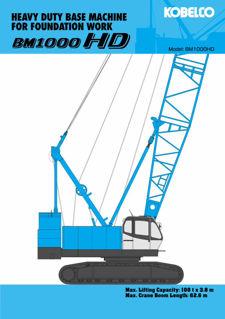
Max. Lifting Capacity: 100 t x 3.8 mMax. Crane Boom Length: 62.6 m
HEAVY DUTY BASE MACHINEFOR FOUNDATION WORK
Model: BM1000HD

1
CONFIGURATION
ClamshellMax. Lifting Capacity:
12.5 metric ton x 13.0 mMax. Boom Length:
26.0 m
Crane BoomMax. Lifting Capacity:
100 metric ton x 3.8 mMax. Boom Length:
62.6 m

2
CONTENTS
Configuration ··················· 1
Specifications ···················· 3
General Dimensions ········· 5
Boom Arrangements ········· 6
Working Ranges and Lifting Capacities
Crane Boom Working Ranges ············· 8
Crane Boom Lifting Capacity ·············· 9
Auxiliary Sheave Lifting Capacityfor Crane Boom ············ 10
Clamshell ·················· 11
Parts and Attachments ··· 12
Hammer GrabBoom Length:
23.0 mLifting Capacity at 7.0 m:
50.9 ton*Recommended Specificationfor Casing Diameter: 2,000 mm
SPECIFICATIONS
3
Model: Hino diesel engine P11C-UNType: Water-cooled, direct fuel injection, with turbochargerCompiles with NRMM (Europe) stage IIIA and US EPA Tier III.Displacement: 10.520 liters Rated Power: 247 kW at 2,000 min-1 {rpm} (ISO)Max. torque: 1,300 N•m/1,500 min-1
Cooling system: Liquid, recirculating bypassStarter: 24 V/6.0 kWRadiator: Corrugated type core, thermostatically controlledAir cleaner: Dry type with replaceable paper elementThrottle: Electric throttle control, twist grip typeFuel filter: Replaceable paper elementBatteries: Two 12V, 136 Ah/5HR capacity batteries, series con-nected.Fuel tank capacity: 400 liters
Three variable displacement piston pumps are driven by heavy-duty pump drive. Two of variable displacement pumps are usedin the main hook hoist circuit, boom hoist circuit, auxiliary hookhoist circuit and each propel circuit. The other is used in theswing circuit.Control: Full-flow hydraulic control system for infinitely variablepressure to front and rear drums, boom hoist brakes andclutches. Controls respond instantly to the touch, deliveringsmooth function operation.Cooling: Oil-to-air heat exchanger (plate-fin type)Filtration: Full-flow and bypass type with replaceable elementElectrical system: All wiring corded for easy servicing, individ-ual fused branch circuits.
Max. relief valve pressure:Load hoist, boom hoist and propel system: 31.9 MPa {325 kgf/cm2}Swing system: 27.5 MPa {280 kgf/cm2}Control system: 7.0 MPa {71 kgf/cm2}
Reservoir capacity: 440 liters
Powered by a hydraulic motor through a planetary reducer.Brake: A spring-set, hydraulically released multiple-disc brakeis mounted on the boom hoist motor and operated through acounter-balance valve.Drum lock: External ratchet for locking drumDrum: Single drum, grooved for 20 mm dia. wire ropeLine speed: Single line on first drum layer
Hoisting, Lowering: 50 to 3 m/min
Diameter of wire ropesBoom guy line: 34 mmBoom hoist reeving: 10 parts of 20 mm dia.high strengthwire rope
Boom backstops: Required for all boom lengths
Front and rear drums for load hoist powered by a hydraulic variable plunger motors, driven through planetary reducers.Positive & Negative Brake: Forced-circulation oil-cooled wet-type multi-disc brake, each using positive and negative actua-tion.The drums are manually locked by the control cable. Bothpositive and negative brake systems are available in lever neu-tral position.Drum lock: External ratchet for locking drum.Drums:
Front drum: 616 mm P.C.D. x 620 mm Lg. wide drum, grooved for 28 mm wire rope. Rope capacity is 200 m working length and 284 m storage length.Rear drum:616 mm P.C.D. x 620 mm Lg. wide drum, grooved for 28 mm wire rope. Rope capacity is 130 m working length and 284 m storage length.Note: Rope lengths listed above denote drum capacity and may differ from actual rope lengths supplied when machinery is shipped.
Line speed: Single line on the first drum layerHoisting, Lowering: 110 to 3 m/min
Line Pull (Single-line):Rated line pull: 132 kN {13.5 tf}Max. line pull: 252.9 kN {25.8 tf} (1st layer)Note: Max. line pull is theoretical values under certain test condition.
Swing unit is powered by hydraulic motor driving spur gearthrough planetary reducer, the swing system provides 360°rotation.Swing parking brakes: A spring-set, hydraulically releasedmultiple-disc brake is mounted on swing motor.Swing circle: Single-row ball bearing with an integral internallycut swing gear.Swing lock: Manually, four position lock for transportationSwing speed: 3.2 min-1 {rpm}
Torsion-free precision machined upper frame. All componentsare located clearly and service friendly. Engine with low noiselevel.Counterweight: 37.8 ton
Power Plant
Load Hoist System
Hydraulic System
Boom Hoisting System
Swing System
Upper Structure
Cab & Control
Totally enclosed, full vision cab with safety glass, fullyadjustable, high backed seat with a head-rest and armrests,and intermittent wiper and window washer (skylight and frontwindow).Cab fittings:Air conditioner, convenient compartment (for tool), cup holder,ashtray, cigarette lighter, sun visor, roof blind, tinted glass, floormat, foot-rest, shoe trayControls:Four adjustable levers for front drum, rear drum, boom drum andswing controls.
Steel-welded carbody with axles. Crawler assemblies aredesigned with quick disconnect feature for individual removalas a unit from axles. Also crawler assemblies can be hydrauli-cally extended for wide-track operation or retracted for trans-portation. Crawler belt tension is maintained by hydraulic jackforce on the track-adjusting bearing block.Carbody weight: 6.8 tCrawler weight: 3.2 tCrawler drive: Independent hydraulic propel drive is built intoeach crawler side frame. Each drive consists of a hydraulicmotor propelling a driving tumbler through a planetary gearbox. Hydraulic motor and gear box are built into the crawlerside frame within the shoe width.Crawler brakes: Spring-set, hydraulically released parkingbrakes are built into each propel drive.Steering mechanism: A hydraulic propel system provides bothskid steering (driving one track only) and counter-rotating steer-ing (driving each track in opposite directions).
4
Lower Structure
Main Specifications (Model: BM1000HD)
Track rollers: Sealed track rollers for maintenance-free opera-tion.Shoes (flat): 59 shoes, 900 mm wide each crawlerMax. travel speed: 1.5/1.0 km/hMax. gradeability: 30%
Including upper and lower machine, 37.8 ton counterweight, 6.8 t carbody weight, 3.2 t crawler weight, basic boom, hook,and other accessories.
Specification Weight Ground pressureCrane boom Approx. 107.4 ton, 109.7 kPa {1.12 kgf/cm2}
BoomWelded lattice construction using tubular, high-tensile steelchords with pin connections between sections.
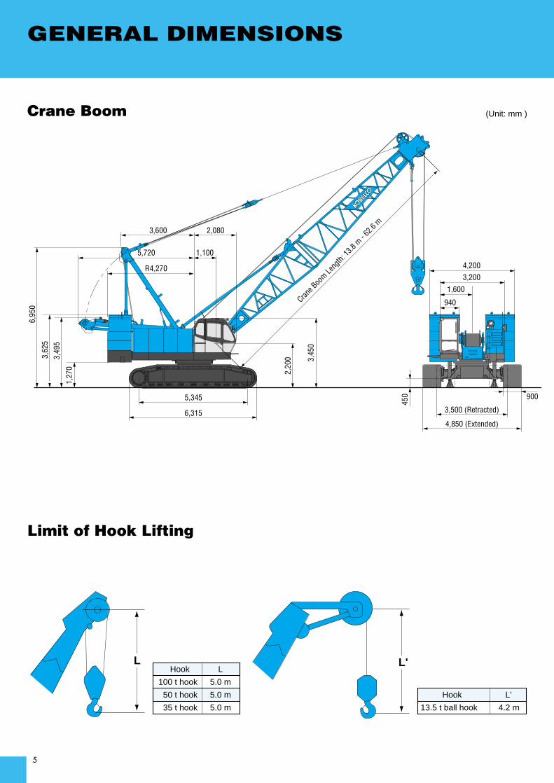
Boom LengthCrane Boom
Basic Boom 13.8 mMax. Boom 62.6 m
Weight
Attachment
Crane BoomMax. Lifting Capacity 100 t/3.8 mMax. Length 62.6 mMain & Aux. WinchMax. Line Speed 110 m/min (1st layer)Rated Line Pull (Single-line) 132 kN {13.5 tf}Max. Line Pull (Single-line)*** 252.9 kN {25.8 tf} (1st layer)Wire Rope Diameter 28 mmWire Rope Length 200 m (Main) 130 m (Aux.)
Brake TypeForced-circulation oil-cooled wet-typemulti-disc brake (Positive & Negative)
Working SpeedSwing Speed 3.2 min-1 {rpm}Travel Speed 1.5/1.0 km/hPower PlantModel Hino P11C-UNEngine Output 247 kW/2,000 min-1
Fuel Tank Capacity 400 liters
Hydraulic SystemMain Pumps 3 variable displacementMax. Pressure 31.9 MPa {325 kgf/cm2}Hydraulic Tank Capacity 440 litersWeightOperating Weight* Approx. 107.4 tGround Pressure* 109.7 kPa {1.12 kgf/cm2}Counterweight 37.8 t (Upper) + 6.8 t (Lower) + 3.2 t (Crawler)Transport Weight** Approx. 35.7 t
* Including upper and lower machine, 37.8 ton counterweight, 6.8 t carbody weight, 3.2 t crawler weight, basic boom, hook and other accessories.
** Base machine with gantry, boom base, carbody, main and aux. winch with wire ropes, lower spreader and upper spreader (Refer to notes P12).
*** Max. line pull is theoretical values under certain test condition.Units are SI units. { } indicates conventional units.
5
GENERAL DIMENSIONS6,
950
3,49
53,
625
6,315
5,345
1,27
0
2,080
1,100
3,600
5,720
R4,2703,2004,200
1,600
940
3,500 (Retracted)
4,850 (Extended)
3,45
0
450 900
Crane B
oom Le
ngth:
13.8
m - 62.6
m
2,20
0
Crane Boom
Limit of Hook Lifting
L L' Hook L
100 t hook 5.0 m
50 t hook 5.0 m
35 t hook 5.0 m
Hook L'
13.5 t ball hook 4.2 m
(Unit: mm )
6
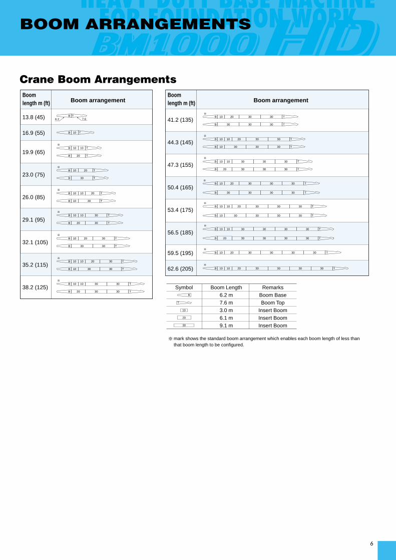
BOOM ARRANGEMENTS
Boom length m (ft) Boom arrangement
13.8 (45)
16.9 (55)
19.9 (65)
23.0 (75)
26.0 (85)
29.1 (95)
32.1 (105)
35.2 (115)
38.2 (125)
Boom length m (ft) Boom arrangement
41.2 (135)
44.3 (145)
47.3 (155)
50.4 (165)
53.4 (175)
56.5 (185)
59.5 (195)
62.6 (205)
mark shows the standard boom arrangement which enables each boom length of less than that boom length to be configured.
Symbol Boom Length6.2 m7.6 m3.0 m6.1 m9.1 m
RemarksBoom BaseBoom Top
Insert BoomInsert BoomInsert Boom
6.2 7.6B T
10B T
※ 10 10B T
20B T
30B T
10 20B T
3030B T
30B T10
※ 10 10 20B T
30B T20
3010 10B T
3030B T10
※ 20 3010B T
3030B T20
303030B T
※ 20 3010 10B T
303030B T10
※ 303010 10B T
※ 20 303010B T
303030B T20
※ 20 303010 10B T
※ 30303010 10B T
※ 20 30303010B T
※ 20 30303010 10B T
※ 3030303010 10B T
※ 20 3030303010B T
※ 10 20 3030303010B T
20
30
10
B
T
20 30303030B T
3030303010B T
30303030B T
※
※
Crane Boom Arrangements

7
A range of hook blocks can be specified, each with a safety latch.
Hook Blocks
No. of lines and max. rated loads (tons)Hooks Weight (kg) No. of
1 2 3 4 5 6 7 8sheaves
100-ton 1,730 4 - - - 50.0 62.5 75.0 87.5 100.050-ton 850 3 - 25.0 37.5 50.0 - - - -35-ton 700 1 - 25.0 35.0 - - - - -
13.5-ton 450 0 13.5 - - - - - - -ball hook
Symbols for Attachments:
Crane BoomAuxiliary Sheavefor Crane Boom

WORKING RANGESAND LIFTING CAPACITIES
8
Hei
gh
t ab
ove
gro
un
d (
m)
Radius from center of rotation (m)
1.1m
Center of rotation
62.6m BOOM
59.5m BOOM
56.5m BOOM
53.4m BOOM
50.4m BOOM
47.3m BOOM
44.3m BOOM
41.2m BOOM
38.2m BOOM
35.2m BOOM
32.1m BOOM
29.1m BOOM
26.0m BOOM
23.0m BOOM
19.9m BOOM
16.9m BOOM
13.8m BOOM
60˚65˚70˚75˚80˚ 55˚
2 4 6 8 10 12 14 16 18 20 22 24 26 28 30 32 34 36 38 40 42 44 46
66
64
24
26
18
28
30
32
34
36
38
40
42
44
46
48
50
52
54
56
58
60
62
16
14
20
22
2.2m
40˚
45˚
50˚
30˚
35˚
Crane Boom Working Ranges
NOTES:1. Ratings according to Japanese Construction Codes for Mobile Cranes
and Japanese Safety Ordinance on Cranes, etc.2. Ratings in metric tons for 360˚ working area.3. Operating radius is the horizontal distance from center of rotation to a
vertical line through the center of gravity of the load.4. Weight of hook block(s), slings and other load handling accessories is
included in rated load. Their total weight must be subtracted from ratedload to obtain weight that can be lifted.
5. Ratings shown are based on freely suspended loads and make noallowance for such factors as wind effect on lifted load, ground condi-tions, out-of-level, operating speeds or any other condition that could bedetrimental to the safe operation of this equipment. Operator, therefore,has the responsibility to judge the existing conditions and reduce liftedloads and operating speeds accordingly.
6. Ratings are for operation on a firm and level surface.7. At radii and boom lengths where no ratings are shown on chart, opera-
tion is not intended nor approved.
8. Boom inserts and guy lines must be arranged as shown in the“Operator's Manual”.
9. Boom hoist reeving is 10 part line.10. Gantry must be in raised position for all conditions.11. Boom backstops are required for all boom lengths.12. Crawler frames must be fully extended for all crane operations.13. Ratings shown in are determined by the strength of the boom
or other structural component.14. Instruction in the “Operator's Manual” must be strictly observed when
operating the machine.15. Crane boom ratings: Deduct weight of main hook block, slings, and all
other load handling accessories from crane boom ratings shown.16. Auxiliary sheave ratings for crane boom: Deduct weight of ball hook,
slings, and all other load handling accessories from auxiliary sheave rat-ings for crane boom shown.
17. Crane boom lengths for auxiliary sheave mounting are 13.8 m to 59.5 m.
9
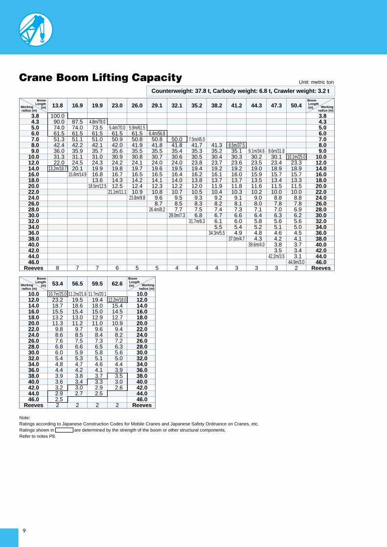
Unit: metric tonCrane Boom Lifting Capacity
Boom Length
(m)Working radius (m)
100.0 90.0 74.0 61.5 51.3 42.4 36.0 31.3 22.0
13.2m/18.7
8
87.574.061.551.142.235.931.124.520.1
15.8m/14.9
7
4.8m/78.073.561.551.042.135.731.024.319.916.813.6
18.5m/12.5
7
13.8 16.9 19.9 23.0
5.4m/70.061.550.942.035.630.924.219.816.714.312.5
21.1m/11.1
6
26.0
5.9m/61.561.550.841.935.530.824.119.716.514.212.410.9
23.8m/9.8
5
29.1
6.4m/56.850.841.835.530.724.019.616.514.112.310.8 9.6 8.7
26.4m/8.2
5
32.1
7.5m/45.041.735.330.523.819.416.213.812.010.5 9.3 8.3 7.5 6.8
31.7m/6.3
4
50.041.835.430.624.019.516.414.012.210.7 9.5 8.5 7.7
29.0m/7.3
4
35.2
3.8 4.3 5.0 6.0 7.0 8.0 9.010.012.014.016.018.020.022.024.026.028.030.032.034.036.038.040.042.044.046.0
Reeves
Boom Length (m) Working
radius (m)
3.8 4.3 5.0 6.0 7.0 8.0 9.010.012.014.016.018.020.022.024.026.028.030.032.034.036.038.040.042.044.046.0
Reeves
Boom Length
(m)Working radius (m)
38.2
41.335.230.423.719.216.113.711.910.4 9.2 8.2 7.4 6.7 6.1 5.5
34.3m/5.5
4
41.2
8.5m/37.535.130.323.619.216.013.711.810.3 9.1 8.1 7.3 6.6 6.0 5.4 4.9
37.0m/4.7
3
44.3
9.1m/34.630.223.519.015.913.511.610.2 9.0 8.0 7.1 6.4 5.8 5.2 4.8 4.3
39.6m/4.0
3
47.3
9.6m/31.830.123.418.915.713.411.510.0 8.8 7.8 7.0 6.3 5.6 5.1 4.6 4.2 3.8 3.5
42.2m/3.5
3
50.4
10.1m/25.023.318.915.713.311.510.0 8.8 7.8 6.9 6.2 5.6 5.0 4.5 4.1 3.7 3.4 3.1
44.9m/3.02
53.4
10.7m/25.023.218.715.513.211.3 9.8 8.6 7.6 6.8 6.0 5.4 4.8 4.4 3.9 3.6 3.2 2.9 2.5
2
59.556.5
11.2m/21.619.518.615.413.011.2 9.7 8.5 7.5 6.6 5.9 5.3 4.7 4.2 3.8 3.4 3.0 2.7
2
12.2m/18.015.414.512.710.9 9.4 8.2 7.2 6.3 5.6 5.0 4.4 3.9 3.5 3.0 2.6
2
11.7m/20.119.418.015.012.911.0 9.6 8.4 7.3 6.5 5.8 5.1 4.6 4.1 3.7 3.3 2.9 2.5
2
62.6
10.012.014.016.018.020.022.024.026.028.030.032.034.036.038.040.042.044.046.0
Reeves
Boom Length (m) Working
radius (m)
10.012.014.016.018.020.022.024.026.028.030.032.034.036.038.040.042.044.046.0
Reeves
Counterweight: 37.8 t, Carbody weight: 6.8 t, Crawler weight: 3.2 t
Note: Ratings according to Japanese Construction Codes for Mobile Cranes and Japanese Safety Ordinance on Cranes, etc.Ratings shown in are determined by the strength of the boom or other structural components.Refer to notes P8.

10
Auxiliary Sheave Lifting Capacity for Crane Boom(With 35 t Main Hook)
Note: Ratings according to Japanese Construction Codes for Mobile Cranes and Japanese Safety Ordinance on Cranes, etc.Ratings shown in are determined by the strength of the boom or other structural components.Refer to notes P8.
Boom Length
(m)Working radius (m)
5.2m/13.513.513.513.513.513.513.513.5
14.6m/12.5
1
5.2m/13.513.513.513.513.513.513.513.513.5
17.2m/12.5
1
5.7m/13.513.513.513.513.513.513.513.513.512.5
19.9m/11.4
1
13.8 16.9 19.9 23.0
6.3m/13.513.513.513.513.513.513.513.513.211.410.3
22.5m/10.0
1
26.0
6.8m/13.513.513.513.513.513.513.513.513.111.3 9.8 8.3
25.2m/7.4
1
29.1
7.3m/13.513.513.513.513.513.513.513.011.2 9.7 8.5 7.5
27.8m/6.6
1
32.1
8.4m/13.513.513.513.513.513.512.710.9 9.4 8.2 7.2 6.4 5.7 5.0
33.1m/4.6
1
7.9m/13.513.513.513.513.513.513.512.911.1 9.6 8.4 7.4 6.6 5.8
30.4m/5.6
1
35.2
5.0 6.0 7.0 8.0 9.010.012.014.016.018.020.022.024.026.028.030.032.034.036.038.040.042.044.0
Reeves
Boom Length (m) Working
radius (m)
5.0 6.0 7.0 8.0 9.010.012.014.016.018.020.022.024.026.028.030.032.034.036.038.040.042.044.0
Reeves
Boom Length
(m)Working radius (m)
38.2
8.9m/13.513.513.513.513.513.512.610.8 9.3 8.1 7.1 6.3 5.6 5.0 4.4
35.7m/3.9
1
41.2
9.4m/13.513.513.513.513.512.610.7 9.2 8.0 7.0 6.2 5.5 4.9 4.3 3.8 3.3
38.4m/3.2
1
44.3
13.513.513.513.512.410.5 9.1 7.9 6.9 6.0 5.3 4.7 4.1 3.7 3.2 2.7
41.0m/2.5
1
47.3
10.5m/13.513.513.513.512.310.4 8.9 7.7 6.7 5.9 5.2 4.5 4.0 3.5 3.1 2.7 2.4 2.2
1
50.4
11.0m/13.513.513.513.512.210.4 8.9 7.7 6.7 5.8 5.1 4.5 3.9 3.4 3.0 2.6 2.3 2.0
1
56.553.4
11.5m/13.513.513.513.512.110.2 8.7 7.5 6.5 5.7 4.9 4.3 3.7 3.3 2.8 2.5 2.1
1
12.6m/13.513.513.511.8 9.9 8.5 7.3 6.2 5.4 4.7 4.0 3.5 3.0 2.6 2.2
1
12.1m/13.513.513.511.910.1 8.6 7.4 6.4 5.5 4.8 4.2 3.6 3.1 2.7 2.3 1.9
1
59.5
10.012.014.016.018.020.022.024.026.028.030.032.034.036.038.040.042.044.0
Reeves
Boom Length (m) Working
radius (m)
10.012.014.016.018.020.022.024.026.028.030.032.034.036.038.040.042.044.0
Reeves
Unit: metric ton
Counterweight: 37.8 t, Carbody weight: 6.8 t, Crawler weight: 3.2 t
11
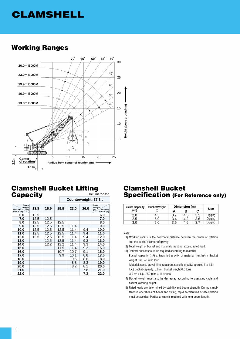
CLAMSHELL
20
2010
30
35˚
30˚
23.0m BOOM
19.9m BOOM
16.9m BOOM
13.8m BOOM
26.0m BOOM
55˚70˚ 65˚ 60˚ 50˚
45˚
40˚
25
15
10
5 15 25
5
1.1m
C
BA Hei
gh
t ab
ove
gro
un
d (
m)
Radius from center of rotation (m)2.2m
Center of rotation
Note:1) Working radius is the horizontal distance between the center of rotation
and the bucket’s center of gravity.2) Total weight of bucket and materials must not exceed rated load.3) Optimal bucket should be required according to material.
Bucket capacity (m3) x Specified gravity of material (ton/m3) + Bucketweight (ton) = Rated loadMaterial: sand, gravel, lime (apparent specific gravity: approx. 1 to 1.8)Ex.) Bucket capacity: 3.0 m3, Bucket weight 6.0 tons3.0 m3 x 1.8 + 6.0 tons = 11.4 tons
4) Bucket weight must also be decreased according to operating cycle andbucket lowering height.
5) Rated loads are determined by stability and boom strength. During simul-taneous operations of boom and swing, rapid acceleration or decelerationmust be avoided. Particular case is required with long boom length.
Working Ranges
Clamshell Bucket LiftingCapacity
Boom Length
(m)Working radius (m)
13.8
12.512.512.512.512.512.512.5
16.9
12.512.512.512.512.512.512.512.2
23.019.9
12.512.512.512.512.512.512.211.510.7 9.9
9.49.49.49.39.39.39.18.88.68.38.17.87.3
11.411.411.411.411.411.411.410.710.1 9.5 8.8 8.2
26.0
6.0 7.0 8.0 9.010.011.012.013.014.015.016.017.018.019.020.021.022.0
Boom Length (m) Working
radius (m)
6.0 7.0 8.0 9.010.011.012.013.014.015.016.017.018.019.020.021.022.0
Clamshell BucketSpecification (For Reference only)
Bucket Capacity(m3)
2.02.53.0
A3.73.43.6
DiggingDiggingDigging
B4.54.24.6
3.23.63.7
CBucket Weight
(t)Dimension (m)
Use
4.55.06.0
Unit: metric ton
Counterweight: 37.8 t

12
PARTS AND ATTACHMENTS
CrawlerWeight: 10,200 kg
1,145
6,315 1,025
900
GantryWeight: 1,400 kg
865
1,240
5,000
Boom BaseWeight: 1,580 kg
6,370 1,730
2,080
Base MachineWith main and aux. winch with wire ropeWeight: 56,100 kg Width: 3,500 mm
Base MachineWith main and aux. winch with wire ropeWeight: 35,700 kg Width: 3,200 mm
Boom TopWeight: 1,800 kg (with boom guy cables)
8,3201,680
1,690
1,700
L (mm) Weight (kg)*
3.0m 3,170 500
6.1m 6,210 800
9.1m 9,260 1100
1,180
950
715
4,200
Counterweight AWeight: 10,000 kg
1,130
800
1,440
Counterweight DWeight: 3,800 kg
1,140
800
1,485
Counterweight EWeight: 4,000 kg
1,180
555
4,200
Counterweight B, CWeight: : 7,500 kg
1,130
1,440
Counterweight FWeight: 2,430 kg
1,135
1,480
Counterweight GWeight: 2,570 kg
675
880 300
Crawler WeightWeight: 800 kg x 4 pieces
1,165
562
1,670
Carbody WeightWeight: 3,400 kg x 2 pieces
*with boom guy cables
Insert Boom
1,690
L 1,670
Dimensions: mm Weight: kg
Other AttachmentsAttachments Dimensions (L x W x H)
1,180 mm x 320 mm x 960 mm4,900 mm x 145 mm dia.
1,780 mm x 305 mm x 800 mm905 mm x 255 mm x 710 mm
700 mm x 540 mm x 2,140 mm700 mm x 430 mm x 1,680 mm700 mm x 470 mm x 1,575 mm
380 mm dia x 1,200 mm
Trans-lifterCrane backstopUpper spreaderLower spreader100-ton hook50-ton hook35-ton hookBall hook
Note: Estimated weights may vary ± 2%.
Weight350 kg130 kg300 kg200 kg
1,730 kg850 kg700 kg450 kg
(1 piece) (1 piece)
3,490
3,520
13,250
3,040
3,070
13,250
3,500

13

14
HEAVY DUTY BASE MACHINEFOR FOUNDATION WORK
Note: Standard equipment may vary depending on your areas or countries.Due to our policy of continual product improvements all designs and specifications are subject to change without advance notice.Copyright by KOBELCO CRANES CO., LTD. No part of this catalog may be reproduced in any manner without notice.
17-1, Higashigotanda 2-chome, Shinagawa-ku, Tokyo 141-8626 JAPANTel: +81-3-5789-2130 Fax: +81-3-5789-3372
Bulletin No. BM1000HD-SPEC-AO1 070501IF Printed in Japan
Inquiries To:
KOBELCO is the corporate mark used by Kobe Steel on a variety of productsand in the names of a number of Kobe Steel Group companies.
Standard Equipment
Upper Structure/Lower Structure
Cab Control
Safety Device
Counterweight: 37.8 ton (total weight)Carbody weight: 6.8 ton (total weight)Crawler weight: 3.2 ton (total weight)900 mm shoe crawlersBatteries (136 Ah/5 HR)Trans-lifter (jack system)Gantry raising/lowering cylinder Electric hand throttle gripVariable boom hoist speed controllerVariable main/aux. hoist speed controllerSide deck for cabSteps (crawlers)Two front working lightsTwo rear view mirrorsTools (for routine maintenance)Upper spreader storage guide
Air conditionerLuggage box Cup holderAshtrayCigar lighterIntermittent wiper & window washer (skylight and front window)Sun visorRoof blindFloor mat (cloth)Foot restShoe tray
Load Moment Indicator (with boom lowering slow stop function)LMI release key (for hook over-hoist prevention device and boom over-hoist prevention device)LCD multi displayUltimate stop function for boom over-hoistFunction lock leverPropel lever lockMechanical drum lock pawl (main, aux. and boom hoist)Signal hornSwing parking brakeMechanical swing lock pin (four positions)Swing flashers/warning buzzer