Embed Size (px)
Citation preview


Introduction 1
HEATLOCK Global Service 2-3
Why Hot Runner ? 4
Gate Diameter 5
Nozzel Features 6
Nozzel Selection Guide Table 7
A1-EN Series 8-9
A1-TP Series 10-11
A1-TN Series 12-13
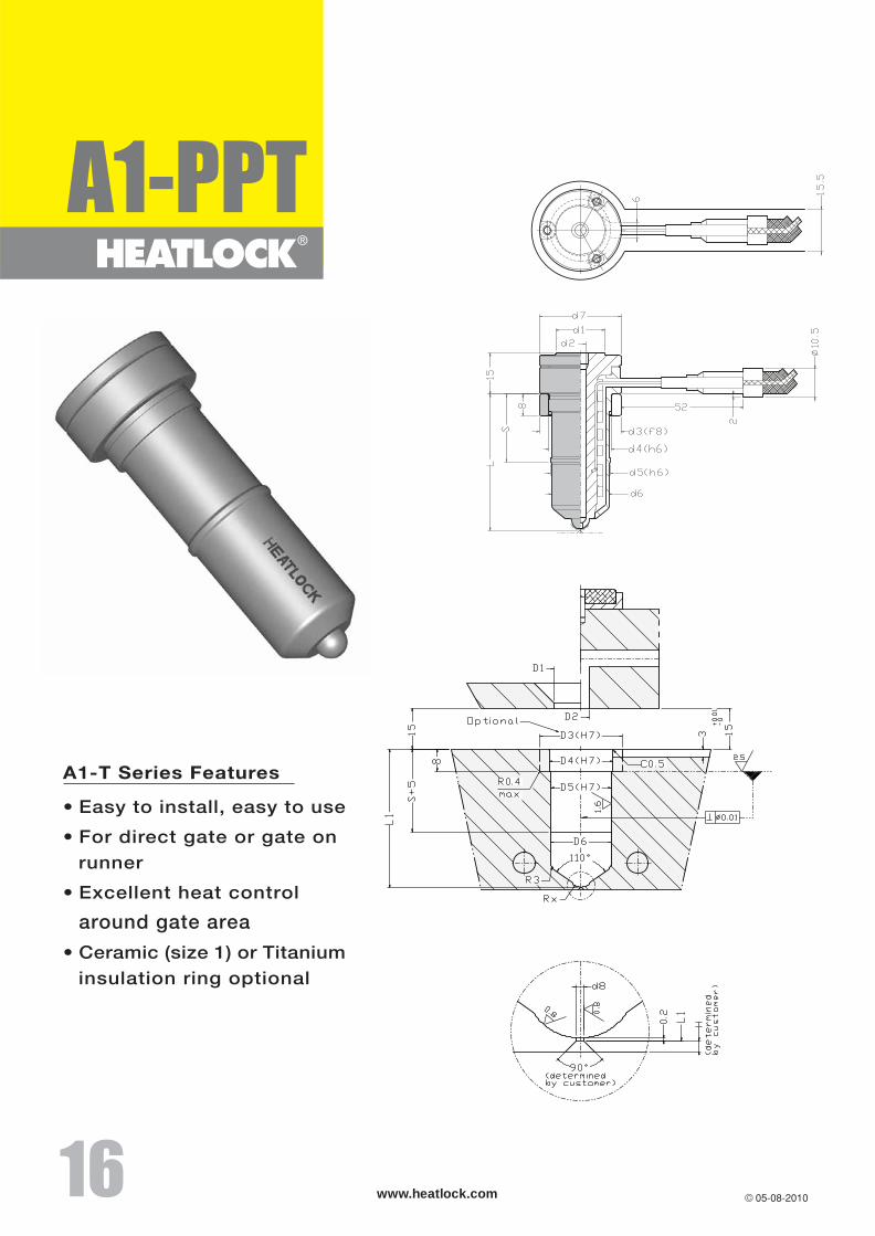
A1-T Series 14-17
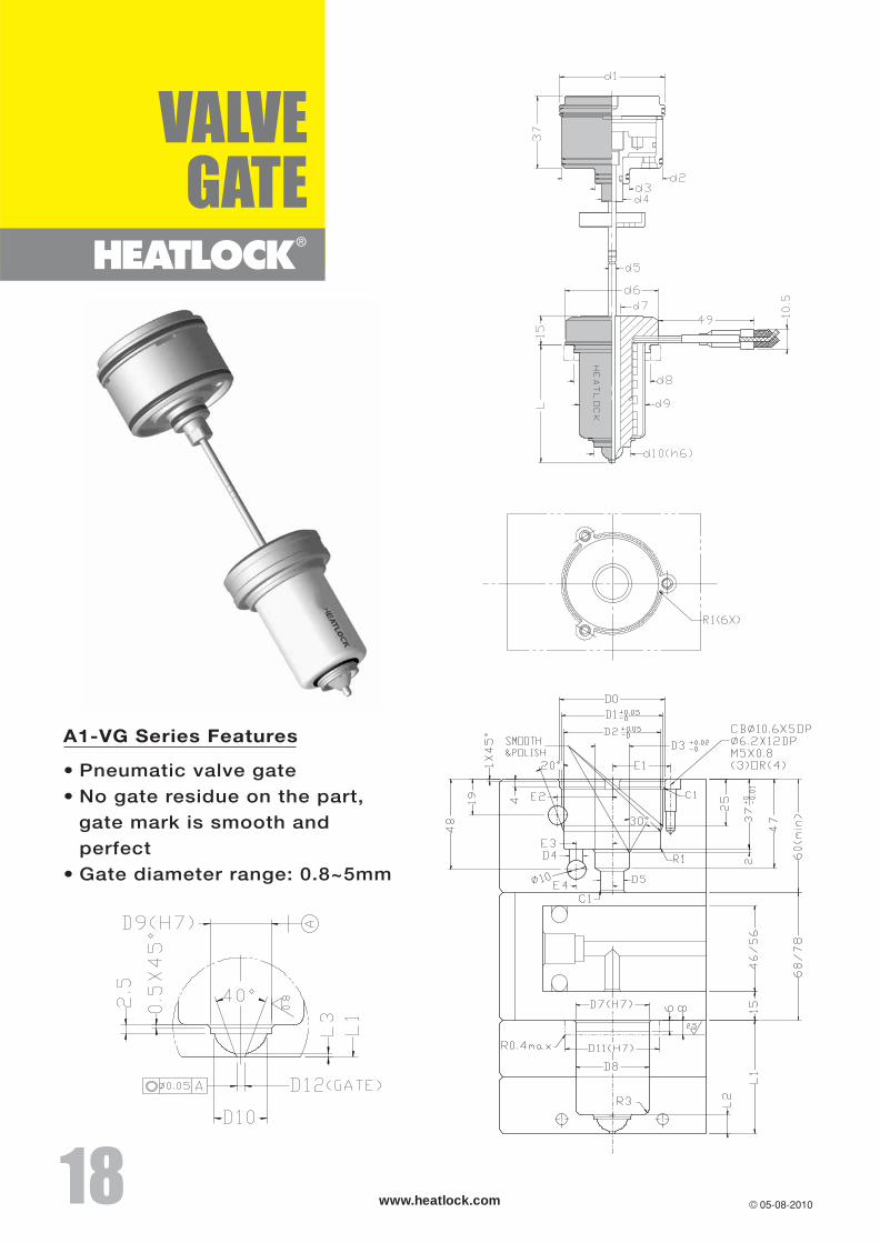
A1-VG Series 18-19
A2-MT Series 20-21
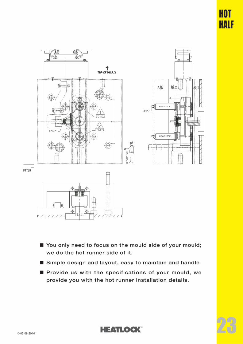
Hot Half 22-23
Hot Runner System Structure 24
Manifold Assembly 25
I(F type) Manifold 26
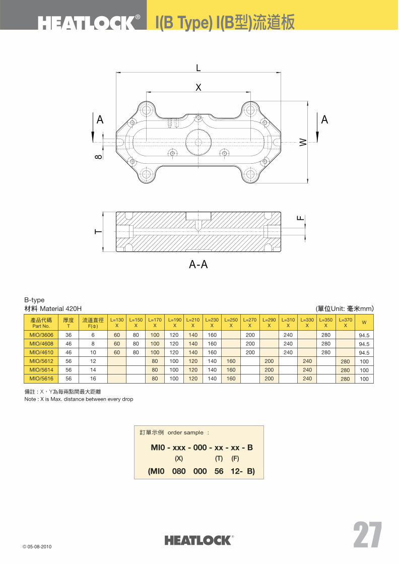
I(B type) Manifold 27
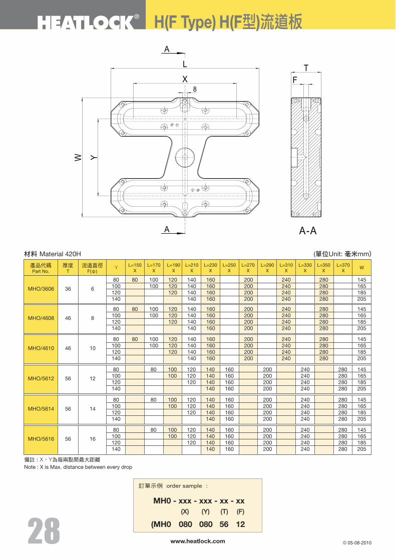
H(F type) Manifold 28
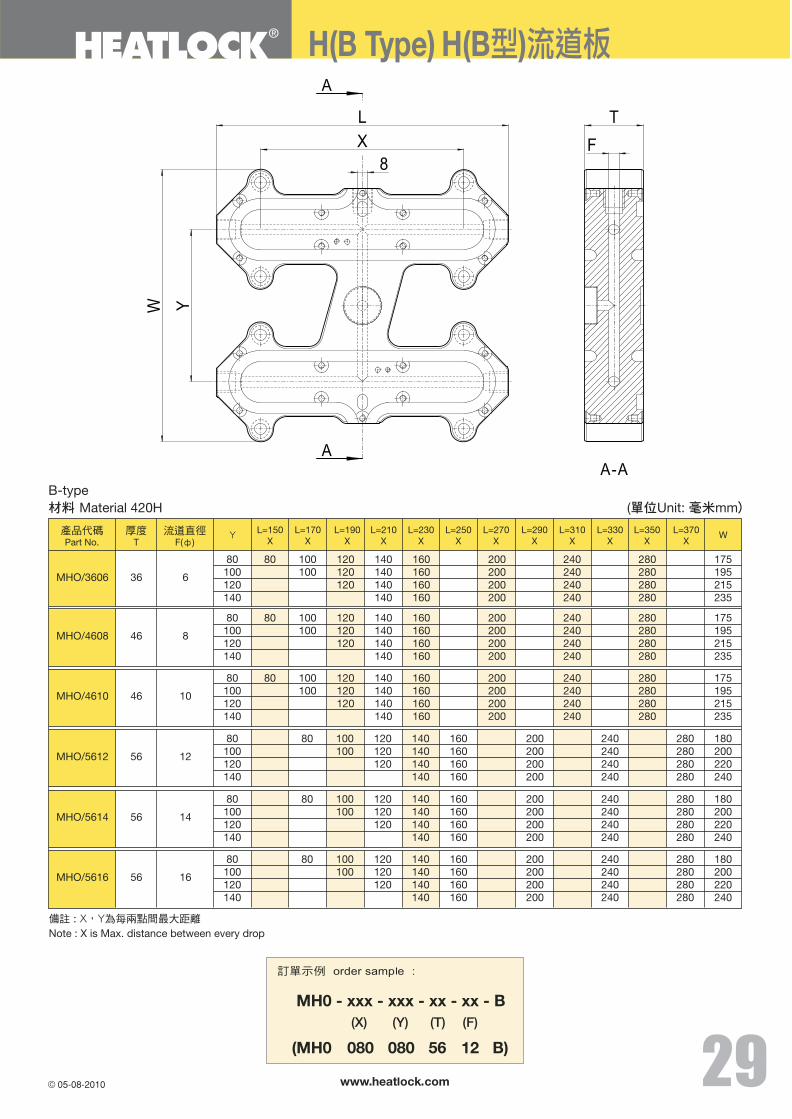
H(B type) Manifold 29
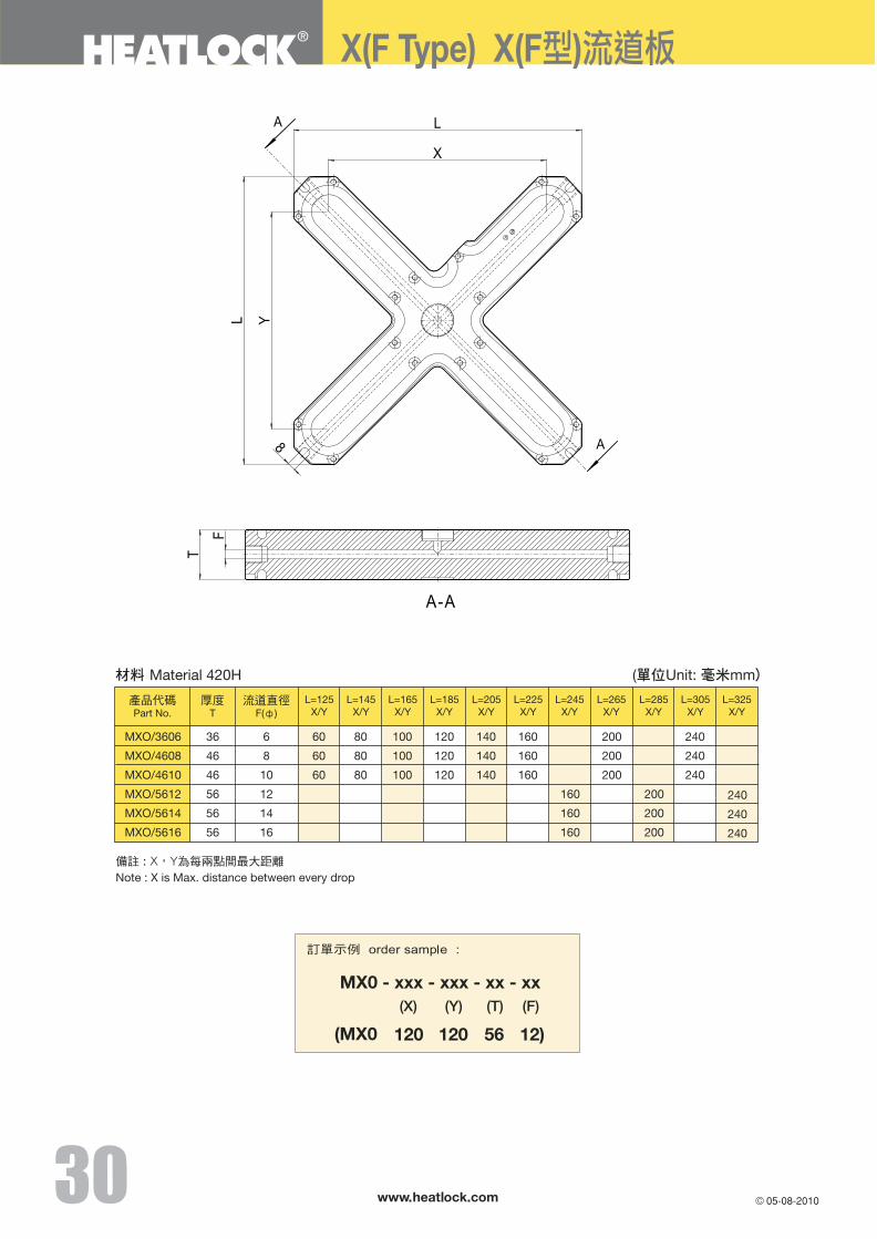
X(F type) Manifold 30
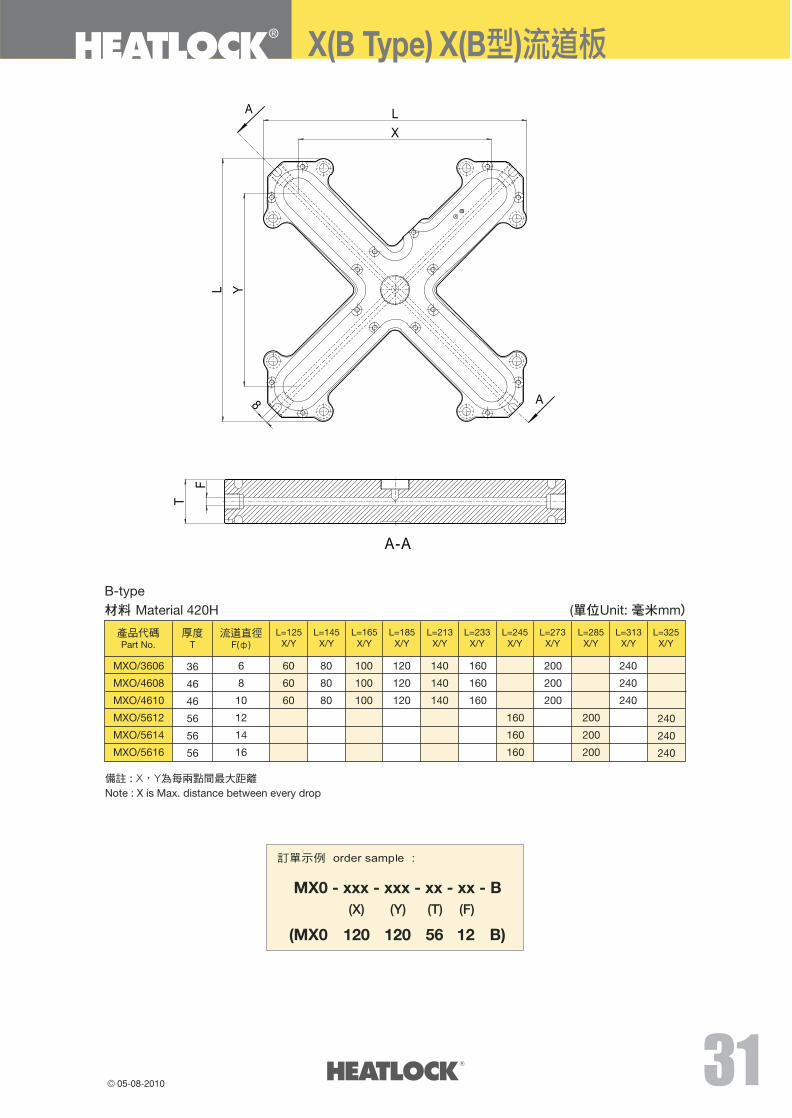
X(B type) Manifold 31
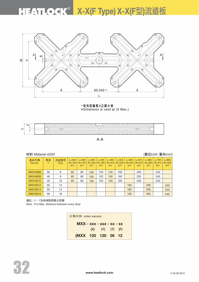
X-X(F type) Manifold 32
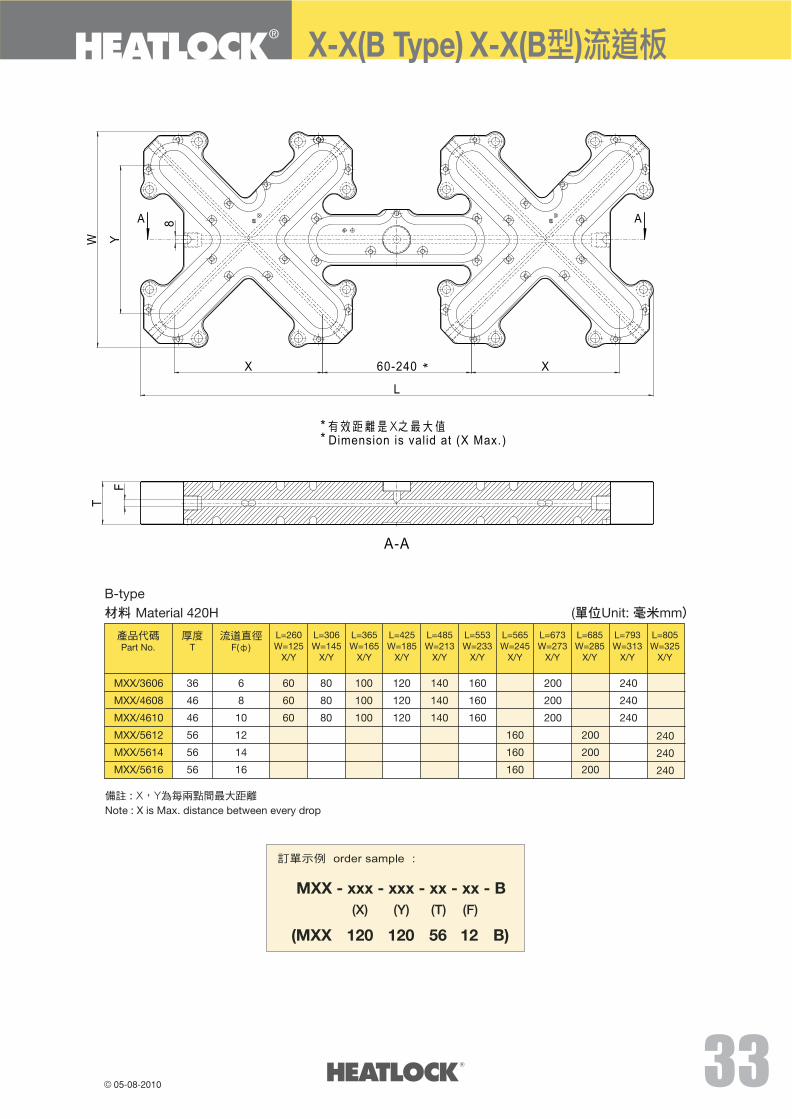
X-X(B type) Manifold 33
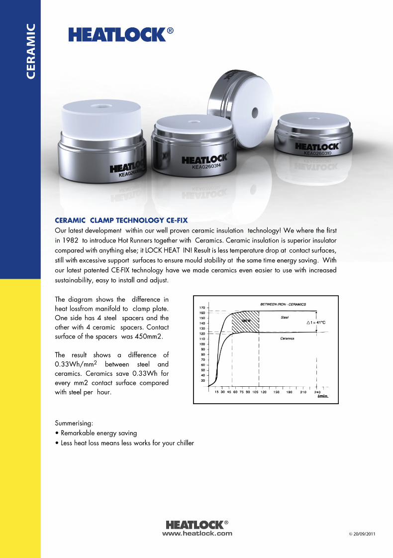
Ceramic 34-35
Titanium Ring 36
Feed Bush Heater 37-38
Connect Box 39-40
US Connect Box 41
Multi Connect Box 42-43
Connector 44
US Connector 45
HLDC-15A 46
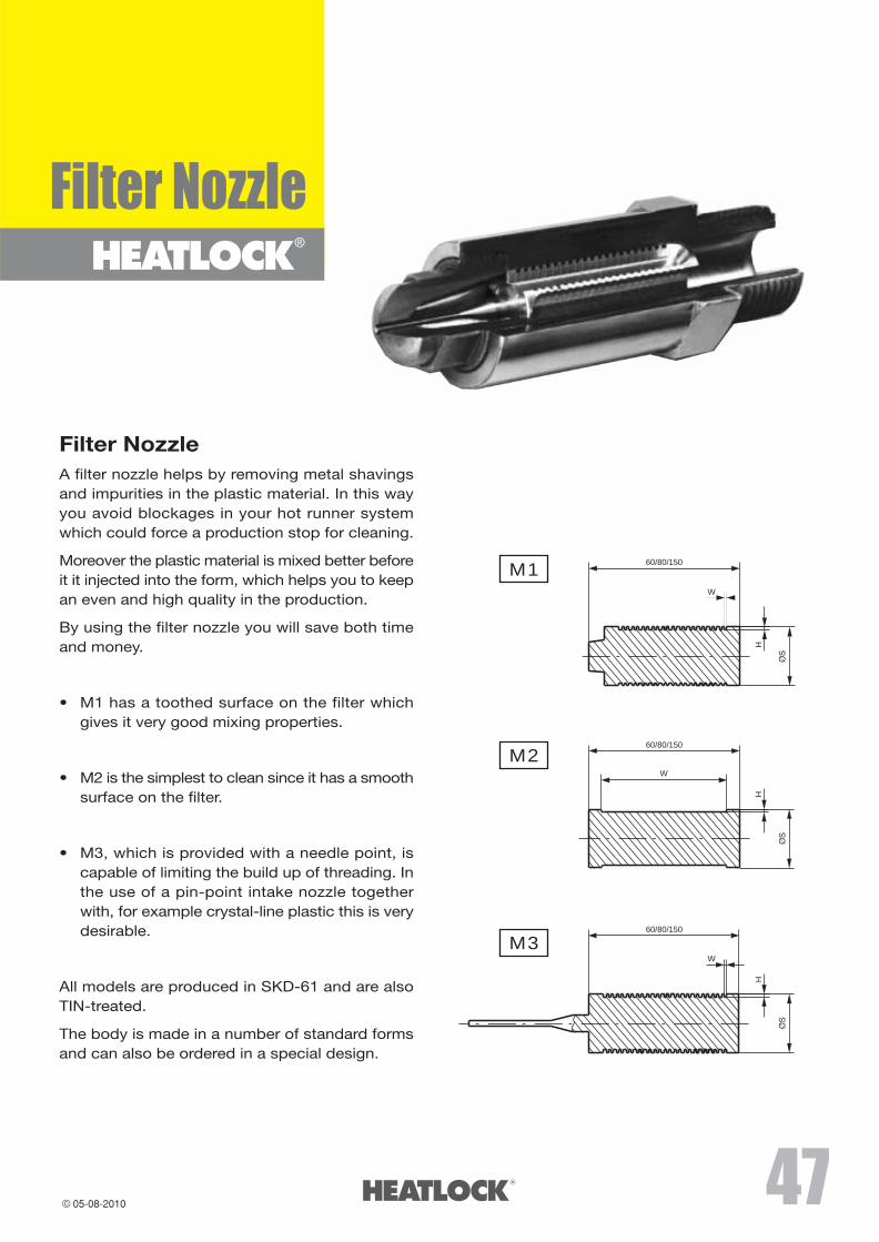
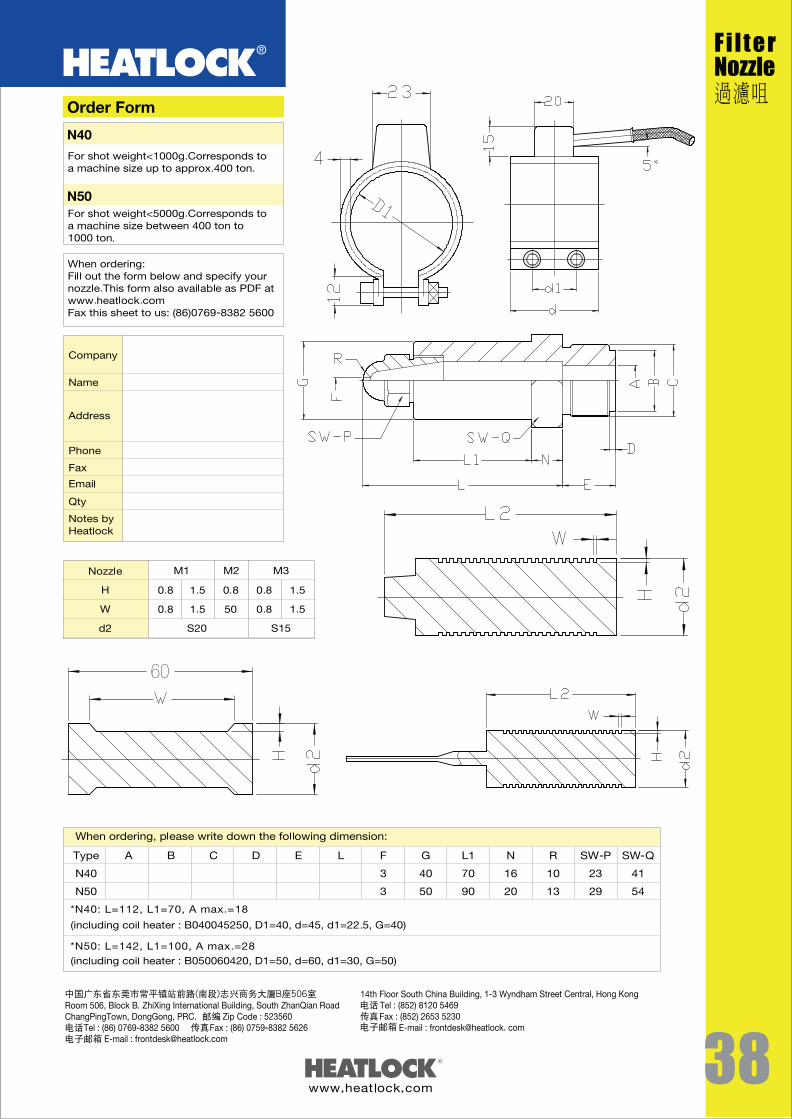
Filter Nozzles 47-48
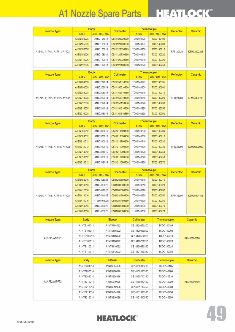
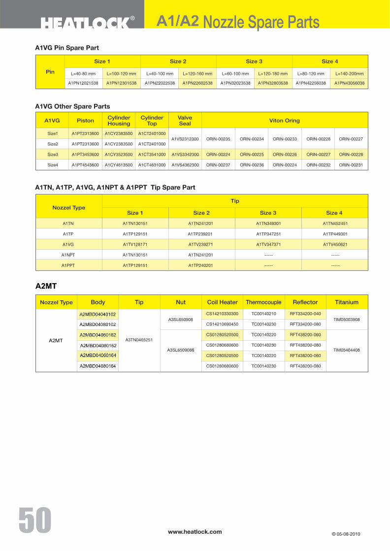
A1 Nozzle Spare Parts 49-50
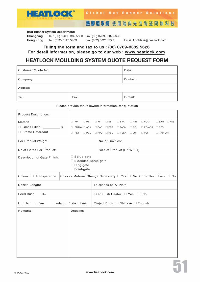
Inquiry Form 51

INTRODUCTIONWELCOME TOHEATLOCK
Your global partner for hot-runner
system technology.
We can offer you excellent localised
service throughout China; the biggest
mould making market in the world, as
well as through our global network of
sales offices and distributors.
Heatlock hot-runners are known for their
ceramic components used for insulating
all the contact points between the hot-
runner system and the mould. Ceramic
has only 7% of the heat conductivity of
steel making it an exceptional insulator.
We were the first in the world to use
this technology for hot-runners and
introduced it at the K82 Exhibition.
Today we deliver everything from single
cavity solutions to complete multi cavity
hot halves. If you require your system
to be proven with simulations do we
also provide it for you.
Our production facility in China is
equipped to manufacture components
and systems to the highest Heatlock
standard with exceptional delivery times
and competitive prices.
Heatlock: Your global partner with the
perfect China connection!

www.heatlock.com
For a complete list of our distributor around the world, please refer to our website :www.heatlock.com
Global Service
���������14th Floor, South China Building1-3 Wyndham StreetCentral Hong KongTel : (852) 8120 5469Fax : (852) 3020 1725E-mail : [email protected]
�Room 506, Block B,ZhiXing International Business BuildingSouth ZhanQian Road, Changping TownGuangdong, PRCZip Code���523560Tel���(86) 0769-8382 5600Fax���(86) 0769-8382 5626E-mail : [email protected]
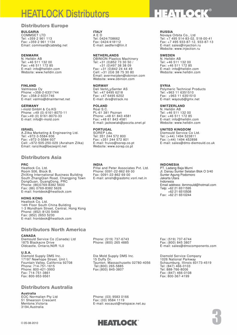
Distributors EuropeBULGARIA ITALY RUSSIACOMMSET LTD A E D Novaya Orbita Co., LtdTel: +359 2 961 113 Tel: 0424/708662 Tel: +7 495 514-83-02, 518-00-41Fax: +359 2 961 1134 Fax: 0424/418112 Fax: +7 495 933-87-12, 933-87-13Email: [email protected] E-mail: [email protected] E-mail: [email protected]
Website: www.injection.ru
DENMARK NETHERLANDS SWEDENN. Helldin AB OBINION Plastics Machinery N. Helldin ABTel: +46 511 132 00 Tel: +31 (0)852 73 30 50 / Tel: +46 511 132 00Fax: +46 511 172 85 +31 (0)497 38 38 09 Fax: +46 511 172 85E-mail: [email protected] Fax: +31 (0)842 24 44 49 E-mail: [email protected] Website: www.helldin.com Cell: +31 (0)6 38 75 30 80 Website: www.helldin.com
Email: [email protected]: www.obinion.com
FINLAND NORWAY SYRIAValmisosa Oy Deli Verkt¿ySenter AS Polymeric Technical ProductsPhone: +358-2-6331744 Tel: +47 6495 6218 Tel: +963 11 6351510Fax: +358-2-6331746 Fax: +47 6495 6202 Fax: +963 11 6351510E-mail: [email protected] E-mail: [email protected] E-mail: [email protected]
GERMANY POLAND SWITZERLANDi-mold GmbH & Co.KG Roal S.C. N. Helldin ABPhone: +49 (0) 6161-8070-11 PL-61 381 Poznan Tel: +46 511 132 00Fax:+49 (0) 6161-8070-33 Phone: +48 61 843 4581 Fax: +46 511 172 85E-mail: [email protected] Fax: +48 61 843 4581 E-mail: [email protected]
E-mail: [email protected] Website: www.helldin.com
ISRAEL PORTUGAL UNITED KINGDOMA.Zilka Marketing & Engineering Ltd. SOREP Lda, Diemould Service Co Ltd.Tel: +972-3-5584-936 Tel: 351 244 572 800 Tel: (+44) 1494 523811Fax: +972-3-5584-937 Fax: +351 244 572 801 Fax: (+44) 1494 452898Cell: +972-505-250-029 (Avraham Zilka) E-mail: [email protected] E-mail: [email protected]: [email protected] Website: www.sorep.co.pt
Distributors AsiaPRC INDIA INDONESIAHeatlock Co. Ltd. Pillai and Peter Associates Pvt. Ltd. PT. Ladang Baja MurniRoom 506, Block B. Phone: 0091-22-862 69 00 Jl. Danau Sunter Selatan Blok O 3/40ZhiXing International Business Building Fax: 0091-22-862 69 00 Sunter Agung PodomoroSouth ZhangQian Road, Changping Town E-mail: [email protected] Jakarta UtaraDongGuan, GuangDong, PRC IndonesiaPhone: (86)0769-8382 5600 Email address: [email protected]: (86) 0769-8382 5626 Telp: +62 21 6511595E-mail: [email protected] +62 21 6510508
Fax: +62 21 6510244HONG KONGHeatlock Co. Ltd.14th Floor South China Building1-3 Wyndham Street, Central, Hong KongPhone: (852) 8120 5469Fax: (852) 2653 5230E-mail: [email protected]
Distributors North AmericaCANADA Diemould Service Co (Canada) Ltd Phone: (519) 737-6743 Fax: (519) 737-67441875 Blackacre Drive Phone: (800) 265 4885 Fax: (800) 845 3807Oldcastle, Ontario,N0R 1L0 E-mail: [email protected]
U.S.A.Diemold Supply DMS Inc. Die Mold Supply DMS Inc. Diemold Service Company17197 Newhope Street, Unit I, 15 Duffy Dr. 1026 National ParkwayFountain Valley, California 92708 Taunton, Massachusetts 02780-4056 Schaumburg, Illinois 60173-4519Phone: 714-751-1615 Tel:(800) 265-5885 Tel: (847) 466-0103Phone: 800-421-3993 Fax:(800) 845-3807 Tel: 888-766-8006Fax: 714-751-3861 Fax: (847) 466-0108Fax: 800-953-9561 Fax: 800-367-4199
Distributors AustraliaAustraliaEOC Normalien Pty Ltd Phone: (03) 9583 0166 51 Shearson Crescent Fax: (03) 9584 1119Mentone,Victoria E-mail: [email protected],Australia
HEATLOCK Distributors
www.heatlock.com
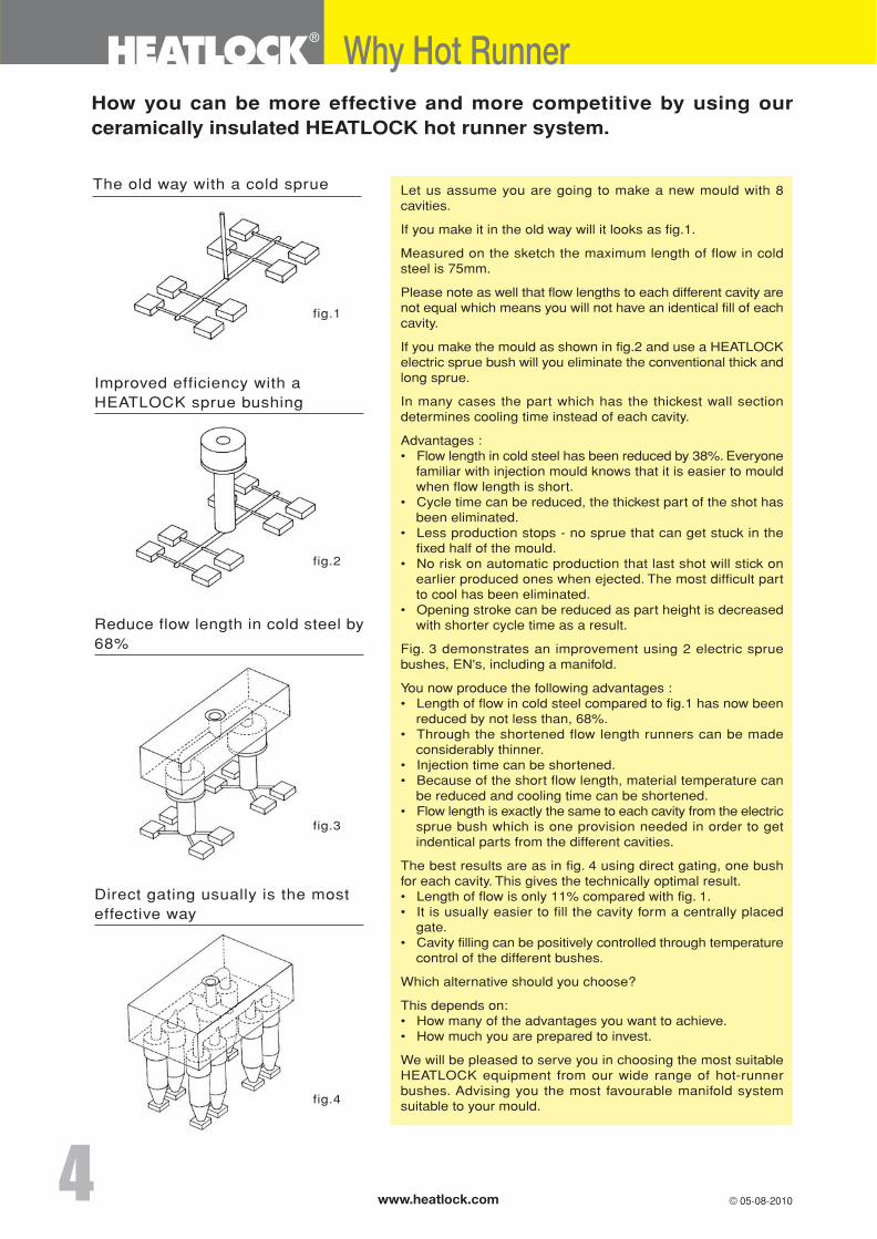
How you can be more effective and more competitive by using ourceramically insulated HEATLOCK hot runner system.
The old way with a cold sprue
fig.1
Improved efficiency with aHEATLOCK sprue bushing
Why Hot Runner
fig.2
Reduce flow length in cold steel by68%
Direct gating usually is the mosteffective way
fig.3
fig.4
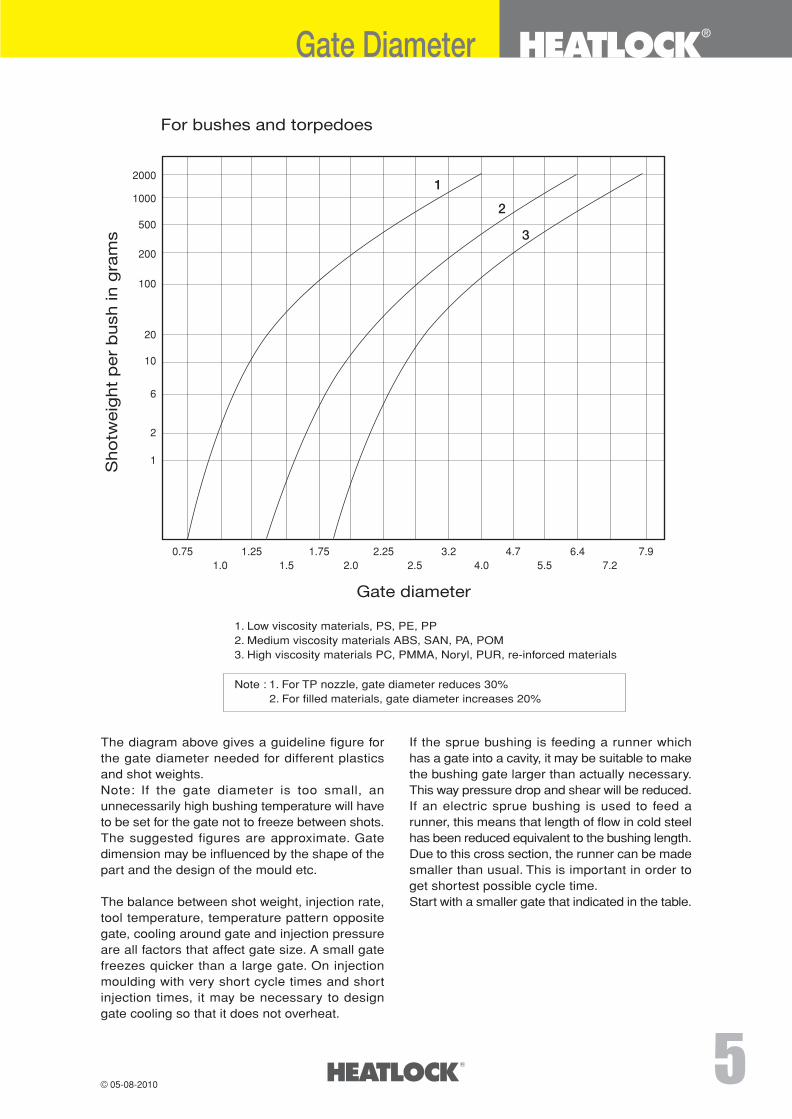
For bushes and torpedoes
0.75 1.25 1.75 2.25 3.2 4.7 6.4 7.91.0 1.5 2.0 2.5 4.0 5.5 7.2
1
2
3
Sh
otw
eig
ht
per
bush
in g
ram
s
Gate diameter
2000
1000
500
200
100
20
10
6
2
1
1. Low viscosity materials, PS, PE, PP2. Medium viscosity materials ABS, SAN, PA, POM3. High viscosity materials PC, PMMA, Noryl, PUR, re-inforced materials
Gate Diameter
The diagram above gives a guideline figure forthe gate diameter needed for different plasticsand shot weights.Note: If the gate diameter is too small, anunnecessarily high bushing temperature will haveto be set for the gate not to freeze between shots.The suggested figures are approximate. Gatedimension may be influenced by the shape of thepart and the design of the mould etc.
The balance between shot weight, injection rate,tool temperature, temperature pattern oppositegate, cooling around gate and injection pressureare all factors that affect gate size. A small gatefreezes quicker than a large gate. On injectionmoulding with very short cycle times and shortinjection times, it may be necessary to designgate cooling so that it does not overheat.
If the sprue bushing is feeding a runner whichhas a gate into a cavity, it may be suitable to makethe bushing gate larger than actually necessary.This way pressure drop and shear will be reduced.If an electric sprue bushing is used to feed arunner, this means that length of flow in cold steelhas been reduced equivalent to the bushing length.Due to this cross section, the runner can be madesmaller than usual. This is important in order toget shortest possible cycle time.Start with a smaller gate that indicated in the table.
Note : 1. For TP nozzle, gate diameter reduces 30%2. For filled materials, gate diameter increases 20%
www.heatlock.com
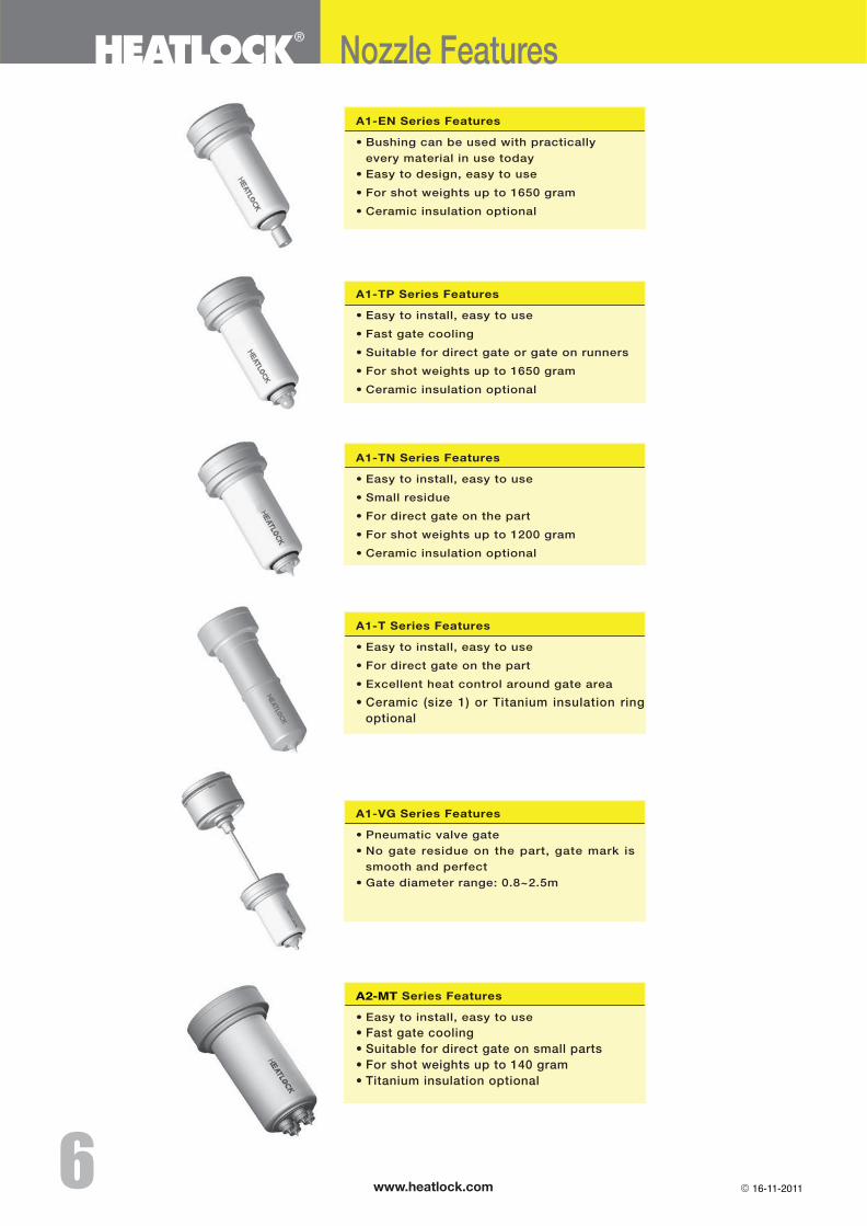
Nozzle Features
16-11-2011
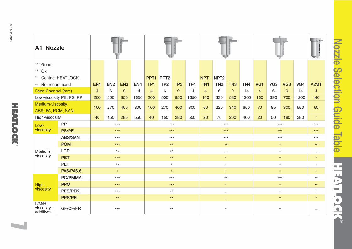
*** Good** Ok* Contact HEATLOCK-- Not recommendFeed Channel (mm)Low-viscosity PE, PS, PPMedium-viscosityABS, PA, POM, SANHigh-viscosity
Low-viscosity
Medium-viscosity
High-viscosity
L/M/Hviscosity +additives
EN1
4200
100
40
********************
***********
***
*****************
**********
**
***********--******----
*
PP
PS/PE
ABS/SAN
POM
LCP
PBT
PET
PA6/PA6.6
PC/PMMA
PPO
PES/PEK
PPS/PEI
GF/CF/FR
***********--*********
--
EN2
6500
270
150
EN3
9850
400
280
EN4
141650
800
550
TP1
4200
100
40
TP2
6500
270
150
TP3
9850
400
280
TP4
141650
800
550
TN1
4140
60
20
TN2
6330
220
70
TN3
9580
340
200
TN4
141200
650
400
A2MT
4140
60
*
VG1
4160
70
20
VG2
6390
85
50
VG3
9700
300
180
VG4
141200
550
380
**************
******
*
A1 Nozzle
Nozzle Selection Guide Table
PPT1 PPT2 NPT1 NPT2
16-11-2011
www.heatlock.com
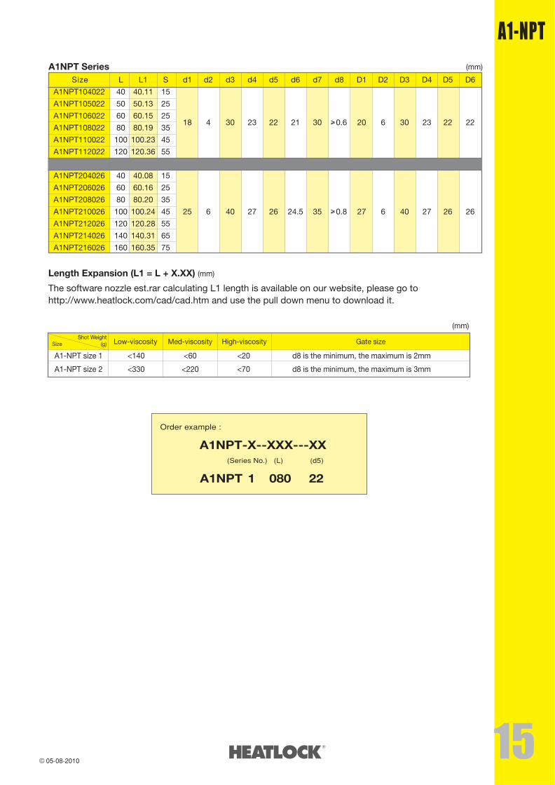
Order example :
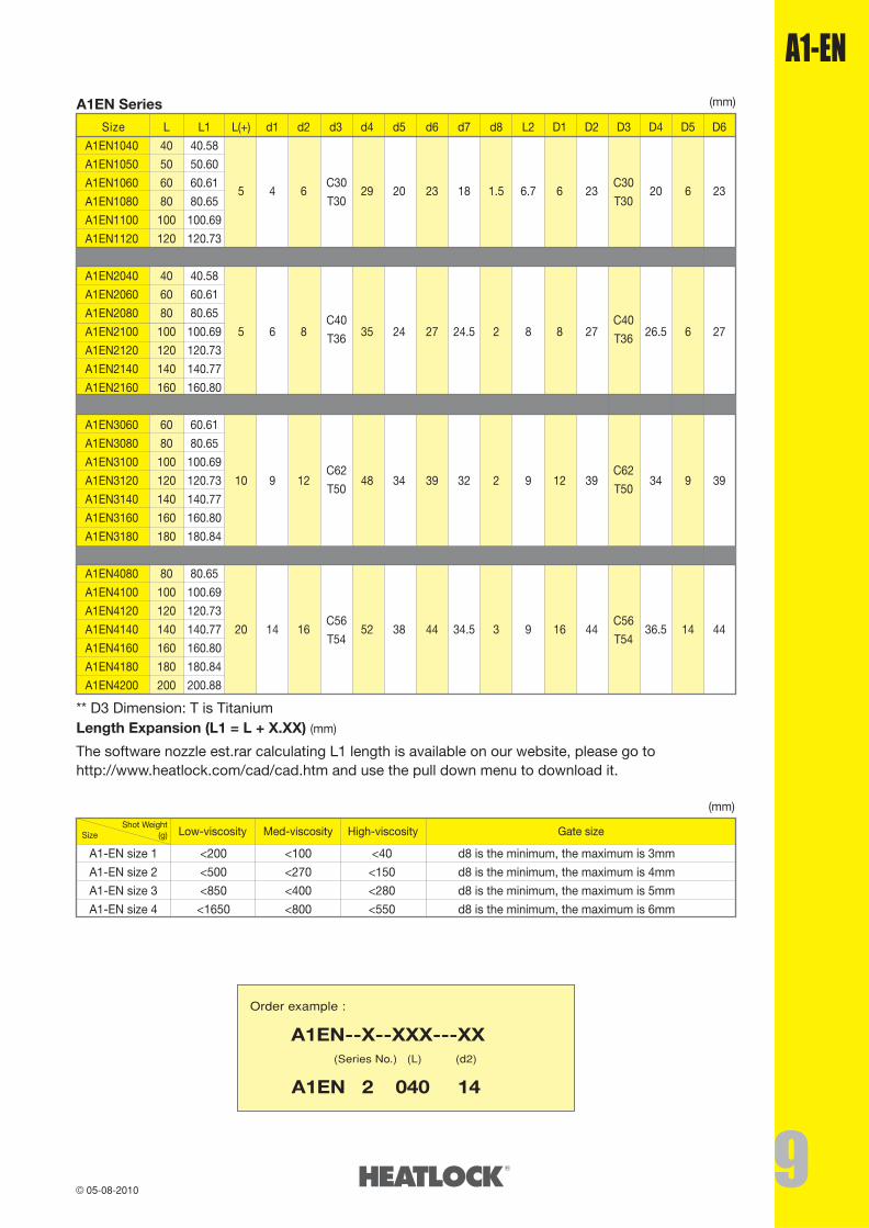
A1EN--X--XXX---XX (Series No.) (L) (d2)
�����������A1EN--2-- 040-- 14
A1EN Series (mm)
Size L L1 L(+) d1 d2 d3 d4 d5 d6 d7 d8 L2 D1 D2 D3 D4 D5 D6
A1EN1040 40 40.58
A1EN1050 50 50.60
A1EN1060 60 60.615 4 6 29 20 23 18 1.5 6.7 6 23 20 6 23
A1EN1080 80 80.65
A1EN1100 100 100.69
A1EN1120 120 120.73
A1EN2040 40 40.58
A1EN2060 60 60.61
A1EN2080 80 80.65
A1EN2100 100 100.69 5 6 8 35 24 27 24.5 2 8 8 27 26.5 6 27
A1EN2120 120 120.73
A1EN2140 140 140.77
A1EN2160 160 160.80
A1EN3060 60 60.61
A1EN3080 80 80.65
A1EN3100 100 100.69
A1EN3120 120 120.73 10 9 12 48 34 39 32 2 9 12 39 34 9 39
A1EN3140 140 140.77
A1EN3160 160 160.80
A1EN3180 180 180.84
A1EN4080 80 80.65
A1EN4100 100 100.69
A1EN4120 120 120.73
A1EN4140 140 140.77 20 14 16 52 38 44 34.5 3 9 16 44 36.5 14 44
A1EN4160 160 160.80
A1EN4180 180 180.84
A1EN4200 200 200.88
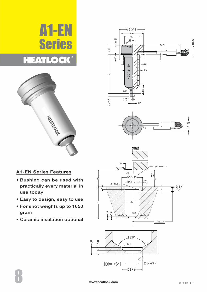
The software nozzle est.rar calculating L1 length is available on our website, please go tohttp://www.heatlock.com/cad/cad.htm and use the pull down menu to download it.
** D3 Dimension: T is Titanium
A1-EN size 1 <200 <100 <40 d8 is the minimum, the maximum is 3mm
A1-EN size 2 <500 <270 <150 d8 is the minimum, the maximum is 4mm
A1-EN size 3 <850 <400 <280 d8 is the minimum, the maximum is 5mm
A1-EN size 4 <1650 <800 <550 d8 is the minimum, the maximum is 6mm
Shot Weight(g)Size Low-viscosity Med-viscosity High-viscosity Gate size
(mm)
Length Expansion (L1 = L + X.XX) (mm)
C30
T30
C30
T30
C40
T36
C40
T36
C62
T50
C62
T50
C56
T54
C56
T54
www.heatlock.com
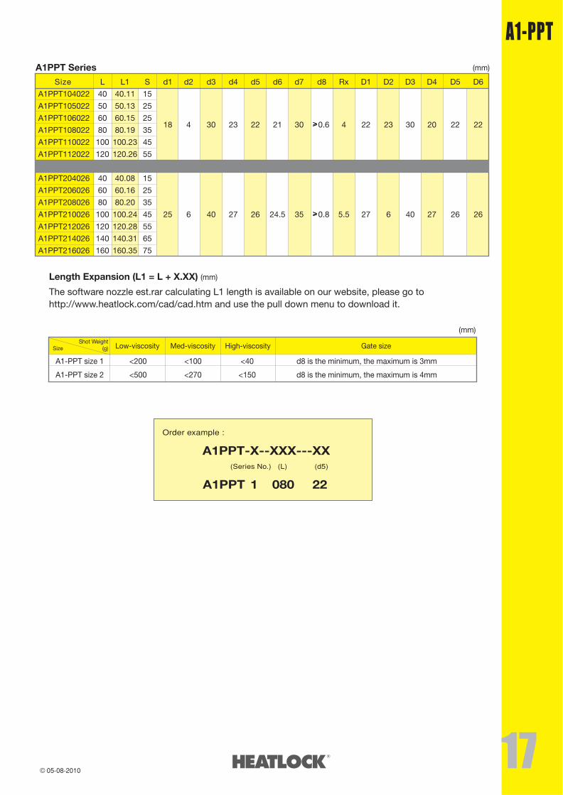
Order example :
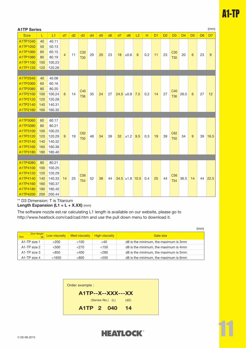
A1TP--X--XXX---XX (Series No.) (L) (d2)
�����������A1TP--2-- 040-- 14
A1TP Series (mm)
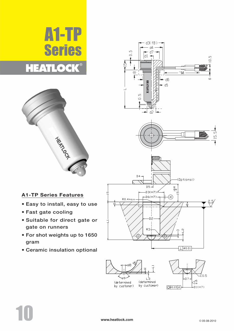
A1-TP size 1 <200 <100 <40 d8 is the minimum, the maximum is 3mm
A1-TP size 2 <500 <270 <150 d8 is the minimum, the maximum is 4mm
A1-TP size 3 <850 <400 <280 d8 is the minimum, the maximum is 5mm
A1-TP size 4 <1650 <800 <550 d8 is the minimum, the maximum is 6mm
Shot Weight(g)Size Low-viscosity Med-viscosity High-viscosity Gate size
(mm)
The software nozzle est.rar calculating L1 length is available on our website, please go tohttp://www.heatlock.com/cad/cad.htm and use the pull down menu to download it.
Length Expansion (L1 = L + X.XX) (mm)** D3 Dimension: T is Titanium
Size L L1 d1 d2 d3 d4 d5 d6 d7 d8 L2 H D1 D2 D3 D4 D5 D6 D7
A1TP1040 40 40.11
A1TP1050 50 50.13
A1TP1060 60 60.15
A1TP1080 80 80.194 11 29 20 23 18 �0.6 6 0.2 11 23 20 6 23 9
A1TP1100 100 100.23
A1TP1120 120 120.26
A1TP2040 40 40.08
A1TP2060 60 60.16
A1TP2080 80 80.20
A1TP2100 100 100.24 6 14 35 24 27 24.5 �0.8 7.5 0.2 14 27 26.5 6 27 12
A1TP2120 120 120.28
A1TP2140 140 140.31
A1TP2160 160 160.35
A1TP3060 60 60.17
A1TP3080 80 80.21
A1TP3100 100 100.25
A1TP3120 120 120.29 9 19 48 34 39 32 �1.2 9.5 0.3 19 39 34 9 39 16.5
A1TP3140 140 140.32
A1TP3160 160 160.36
A1TP3180 180 180.40
A1TP4080 80 80.21
A1TP4100 100 100.25
A1TP4120 120 120.29
A1TP4140 140 140.33 14 25 52 38 44 34.5 �1.8 10.5 0.4 25 44 36.5 14 44 22.5
A1TP4160 160 160.37
A1TP4180 180 180.40
A1TP4200 200 200.44
C30
T30
C30
T30
C40
T36
C40
T36
C62
T50
C62
T50
C56
T54
C56
T54
www.heatlock.com
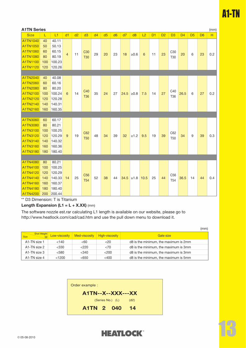
A1TN Series (mm)
The software nozzle est.rar calculating L1 length is available on our website, please go tohttp://www.heatlock.com/cad/cad.htm and use the pull down menu to download it.
Length Expansion (L1 = L + X.XX) (mm)
Size L L1 d1 d2 d3 d4 d5 d6 d7 d8 L2 D1 D2 D3 D4 D5 D6 H
A1TN1040 40 40.11
A1TN1050 50 50.13
A1TN1060 60 60.15
A1TN1080 80 80.194 11 29 20 23 18 �0.6 6 11 23 20 6 23 0.2
A1TN1100 100 100.23
A1TN1120 120 120.26
A1TN2040 40 40.08
A1TN2060 60 60.16
A1TN2080 80 80.20
A1TN2100 100 100.24 6 14 35 24 27 24.5 �0.8 7.5 14 27 26.5 6 27 0.2
A1TN2120 120 120.28
A1TN2140 140 140.31
A1TN2160 160 160.35
A1TN3060 60 60.17
A1TN3080 80 80.21
A1TN3100 100 100.25
A1TN3120 120 120.29 9 19 48 34 39 32 �1.2 9.5 19 39 34 9 39 0.3
A1TN3140 140 140.32
A1TN3160 160 160.36
A1TN3180 180 180.40
A1TN4080 80 80.21
A1TN4100 100 100.25
A1TN4120 120 120.29
A1TN4140 140 140.33 14 25 52 38 44 34.5 �1.8 10.5 25 44 36.5 14 44 0.4
A1TN4160 160 160.37
A1TN4180 180 180.40
A1TN4200 200 200.44
** D3 Dimension: T is Titanium
Order example :
A1TN--X--XXX---XX (Series No.) (L) (d2)
�����������A1TN--2-- 040-- 14
A1-TN size 1 <140 <60 <20 d8 is the minimum, the maximum is 2mm
A1-TN size 2 <330 <220 <70 d8 is the minimum, the maximum is 3mm
A1-TN size 3 <580 <340 <200 d8 is the minimum, the maximum is 3mm
A1-TN size 4 <1200 <650 <400 d8 is the minimum, the maximum is 5mm
Shot Weight(g)Size Low-viscosity Med-viscosity High-viscosity Gate size
(mm)
C30
T30
C30
T30
C40
T36
C40
T36
C62
T50
C62
T50
C56
T54
C56
T54
www.heatlock.com
www.heatlock.com
www.heatlock.com
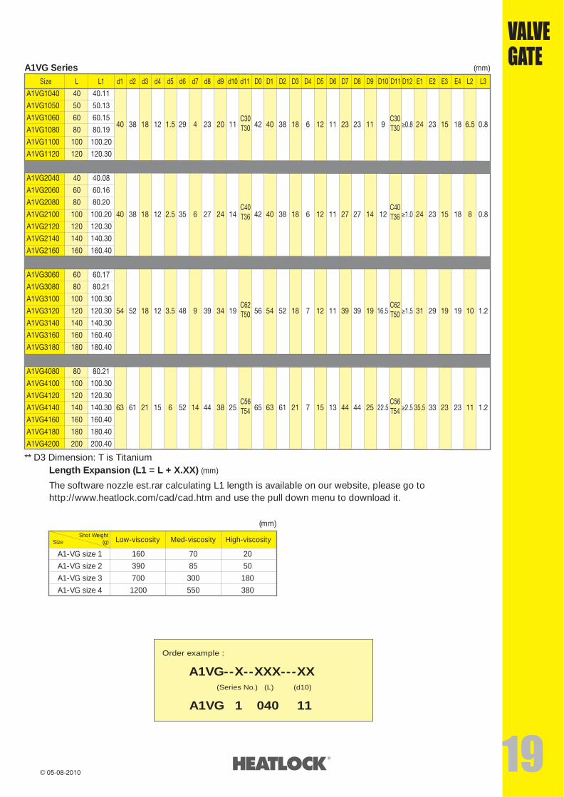
A1VG Series (mm)
The software nozzle est.rar calculating L1 length is available on our website, please go tohttp://www.heatlock.com/cad/cad.htm and use the pull down menu to download it.
Length Expansion (L1 = L + X.XX) (mm)
** D3 Dimension: T is Titanium
Order example :
A1VG--X--XXX---XX (Series No.) (L) (d10)
�����������A1VG--1-- 040-- 11
A1-VG size 1 160 70 20
A1-VG size 2 390 85 50
A1-VG size 3 700 300 180
A1-VG size 4 1200 550 380
Shot Weight(g)Size Low-viscosity Med-viscosity High-viscosity
(mm)
www.heatlock.com 16-11-2011
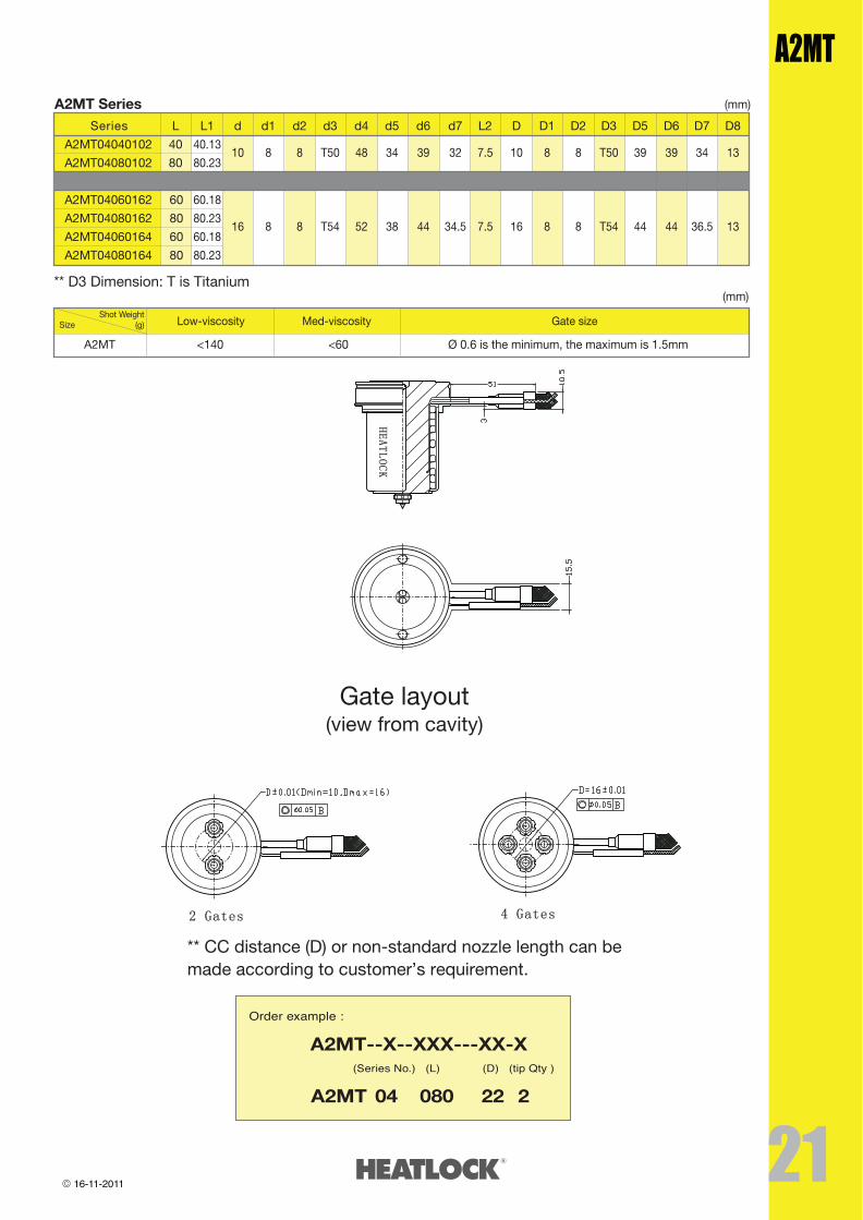
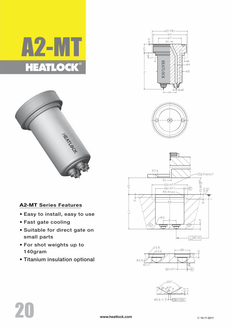
A2MT Series (mm)
Series L L1 d d1 d2 d3 d4 d5 d6 d7 L2 D D1 D2 D3 D5 D6 D7 D8
A2MT04040102 40 40.1310 8 8 T50 48 34 39 32 7.5 10 8 8 T50 39 39 34 13
A2MT04080102 80 80.23
A2MT04060162 60 60.18
A2MT04080162 80 80.2316 8 8 T54 52 38 44 34.5 7.5 16 8 8 T54 44 44 36.5 13
A2MT04060164 60 60.18
A2MT04080164 80
A2MT
80.23
** D3 Dimension: T is Titanium
Gate layout(view from cavity)
Order example :
Shot Weight(g)Size Low-viscosity Med-viscosity Gate size
(mm)
A2MT--X--XXX---XX-X (Series No.) (L) (D) (tip Qty )
A2MT-04-- 080-- 22- 2
16-11-2011
A2MT
www.heatlock.com��
��
www.heatlock.com
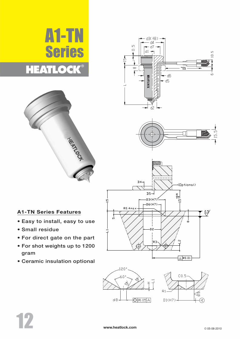
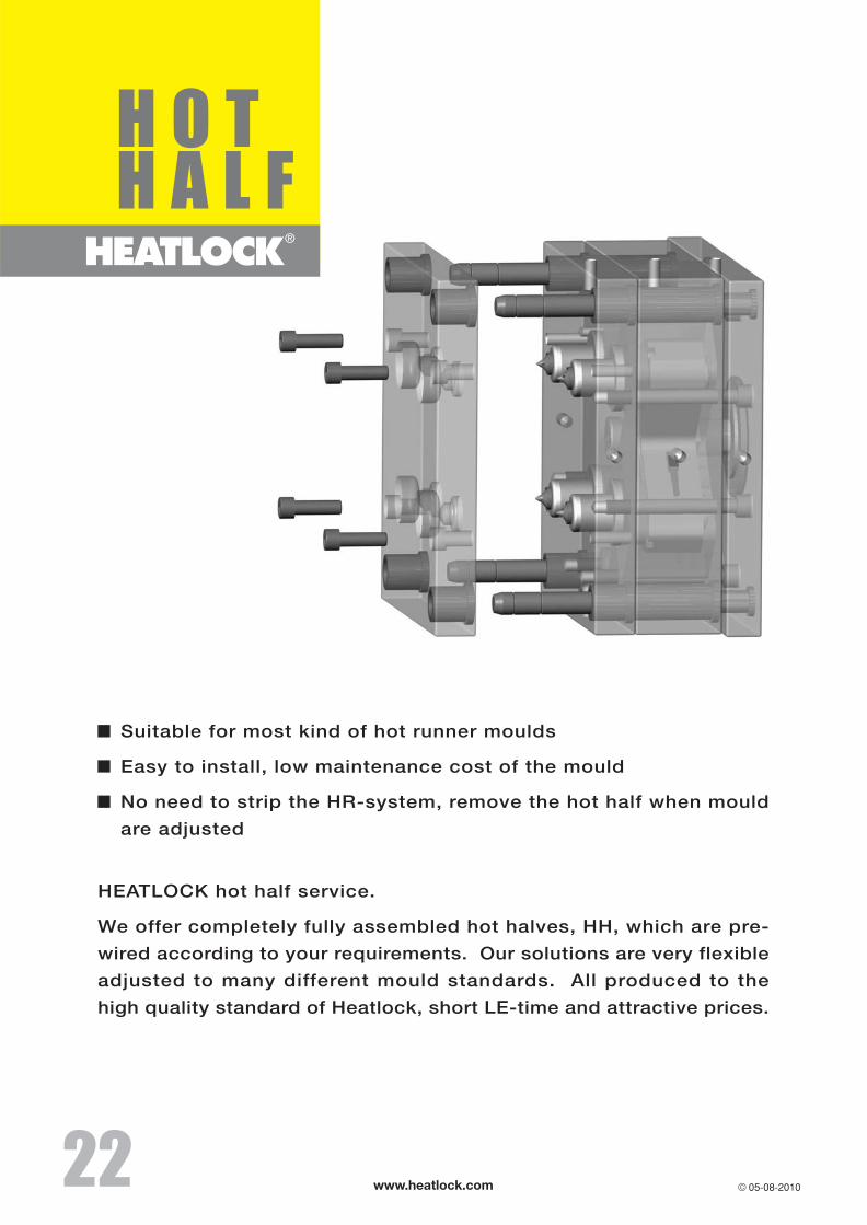
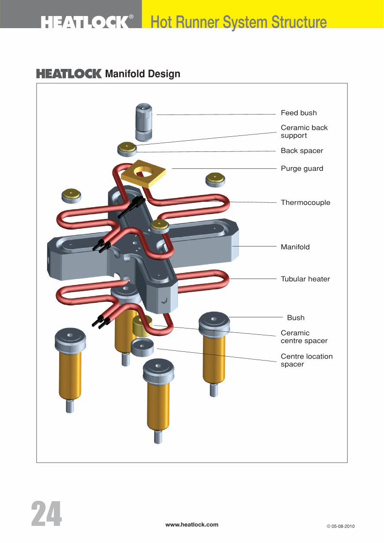
Manifold Design
Hot Runner System Structure
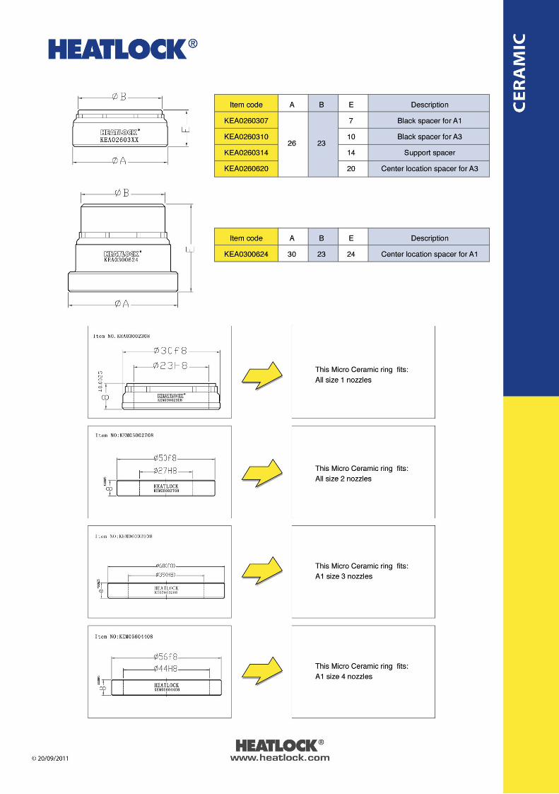
Feed bush
Ceramic backsupport
Back spacer
Purge guard
Thermocouple
Tubular heater
Bush
Ceramiccentre spacer
Centre locationspacer
Manifold
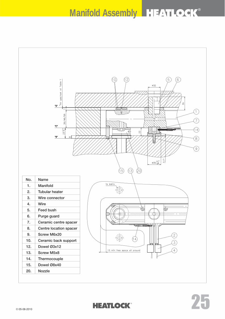
Manifold Assembly
��
��
��
��
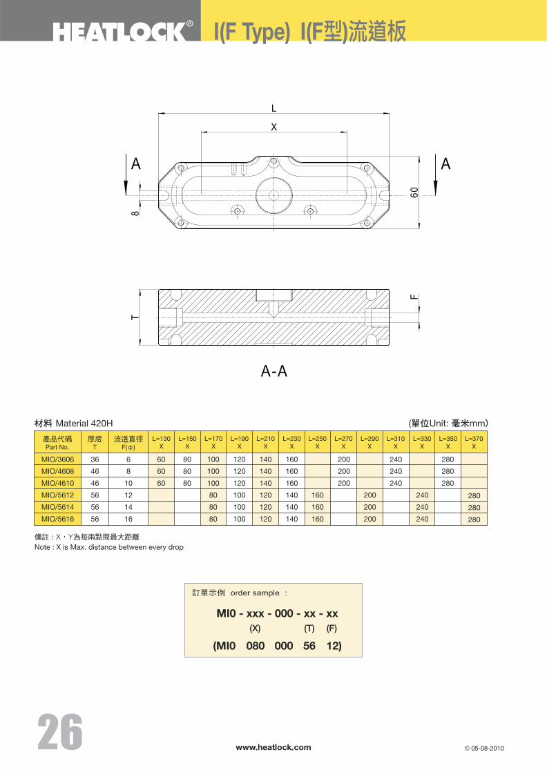
36
46
46
56
56
56
100
100
100
��
��
www.heatlock.com
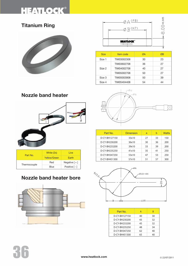
Titanium Ring
Nozzle band heater
Nozzle band heater bore
Size 1 TIM03002308 30 23
TIM03602708 36 27
Size 2 TIM04002708 40 27
TIM05002708 50 27
Size 3 TIM05003908 50 39
Size 4 TIM05404408 54 44
Item codeSize
White (2x)Part No.
Live
Yellow/Green Earth
ThermocoupleRed Negative [ + ]
Blue Positive [ - ]
22/07/2011
D-CY-BH127150 40 30 D-CY-BH230200 43 32 D-CY-BH233200 45 32 D-CY-BH235250 48 34 D-CY-BH347250 62 40 D-CY-BH451300 65 40
Part No. A B
D-CY-BH127150 33x10 27 33 150
D-CY-BH230200 36x10 30 36 200
D-CY-BH233200 39x10 33 39 200
D-CY-BH235250 41x10 35 41 250
D-CY-BH347250 53x10 47 53 250
D-CY-BH451300 57x10 51 57 300
DimensionPart No. a b Watts
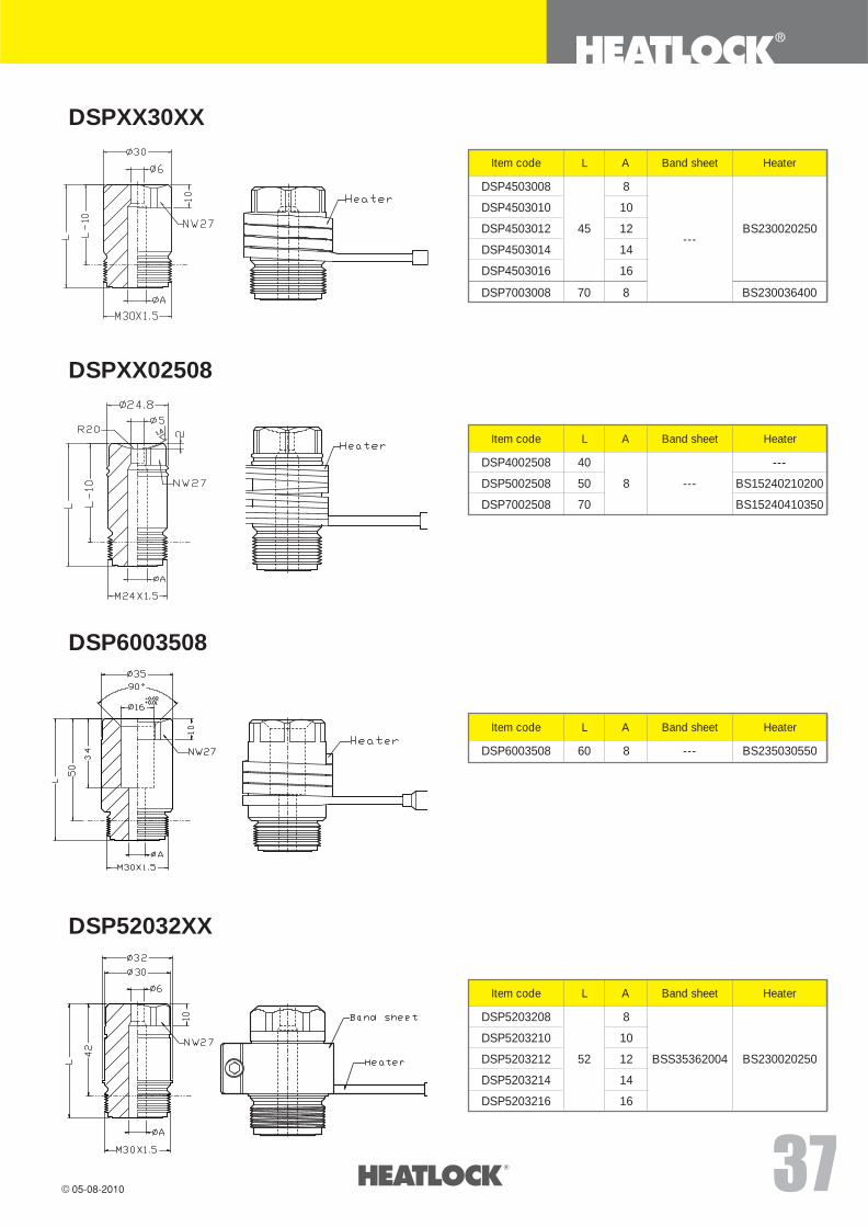
DSPXX30XX
DSP4503008
DSP4503010
DSP4503012
DSP4503014
DSP4503016
Item code L A Band sheet Heater
8
10
12
14
16
45---
BS230020250
DSP7003008 70 8 BS230036400
DSPXX02508
DSP4002508
DSP5002508
DSP7002508
Item code L A Band sheet Heater
8
40
50
70
---
---
BS15240210200
BS15240410350
DSP6003508
DSP6003508
Item code L A Band sheet Heater
860 --- BS235030550
DSP52032XX
DSP5203208
DSP5203210
DSP5203212
DSP5203214
DSP5203216
Item code L A Band sheet Heater
8
10
12
14
16
52 BSS35362004 BS230020250
www.heatlock.com
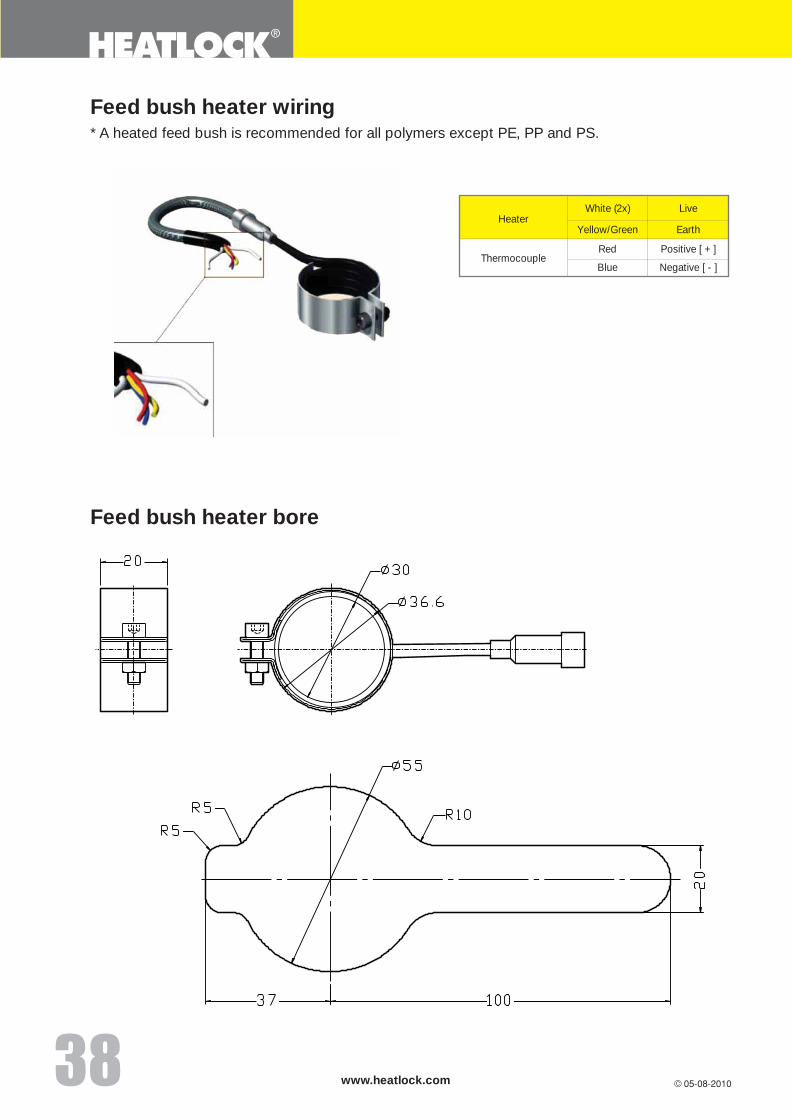
* A heated feed bush is recommended for all polymers except PE, PP and PS.
Feed bush heater wiring
White (2x)Heater
Live
Yellow/Green Earth
ThermocoupleRed Positive [ + ]
Blue Negative [ - ]
Feed bush heater bore
��
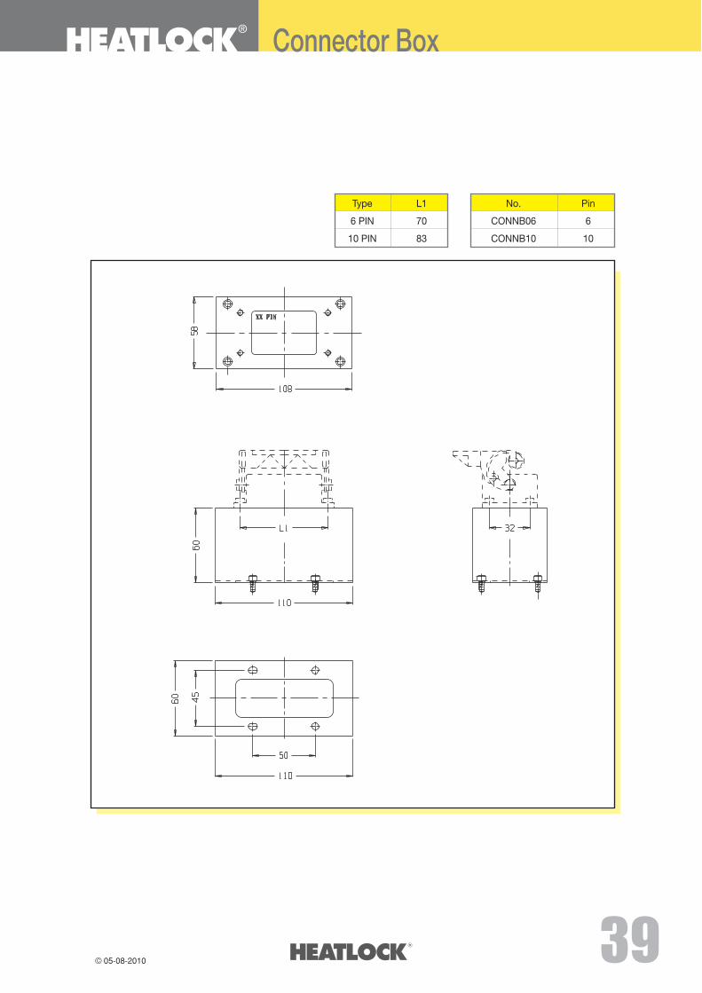
Connector Box
Type L1
6 PIN 70
10 PIN 83
No. Pin
CONNB06 6
CONNB10 10
www.heatlock.com��
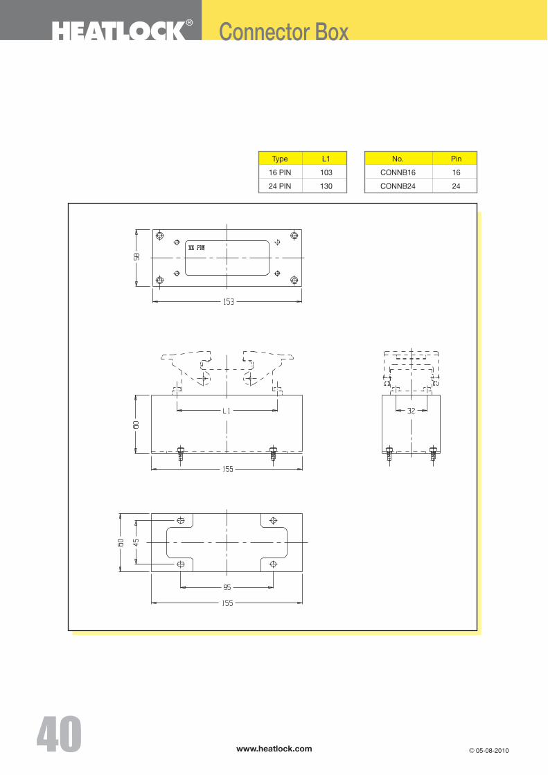
Connector Box
Type L1
16 PIN 103
24 PIN 130
No. Pin
CONNB16 16
CONNB24 24
��
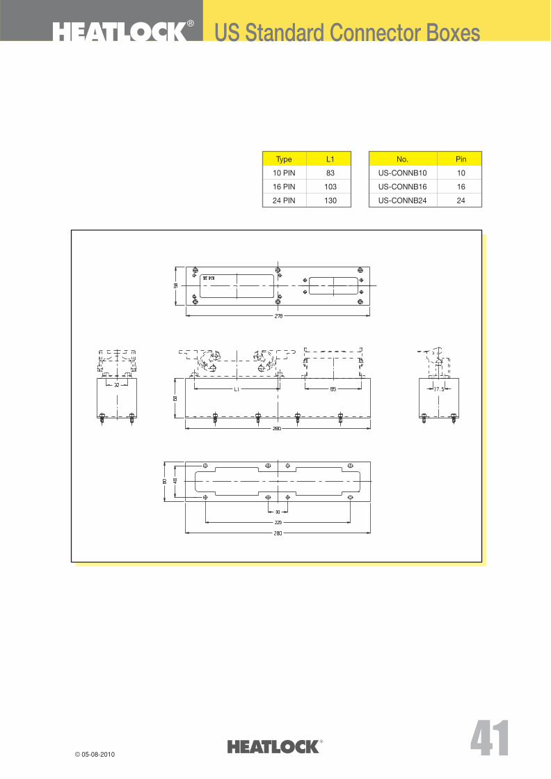
US Standard Connector Boxes
Type L1
10 PIN 83
16 PIN 103
24 PIN 130
No. Pin
US-CONNB10 10
US-CONNB16 16
US-CONNB24 24
www.heatlock.com��
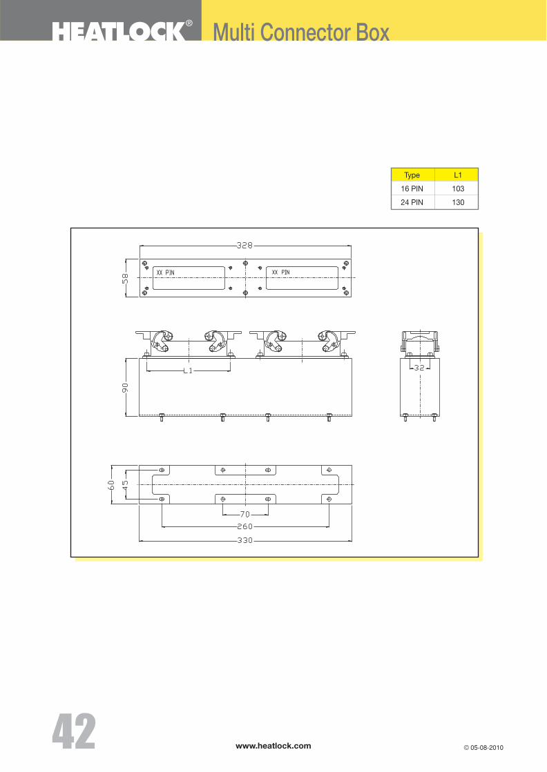
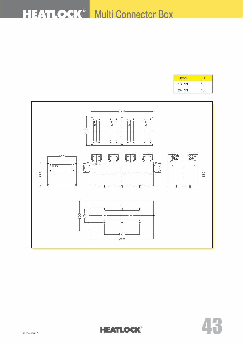
Multi Connector Box
Type L1
16 PIN 103
24 PIN 130
��
Multi Connector Box
Type L1
16 PIN 103
24 PIN 130
No.
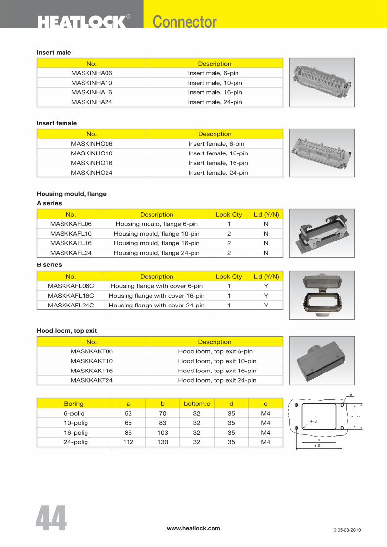
MASKINHA06
MASKINHA10
MASKINHA16
MASKINHA24
Description
Insert male, 6-pin
Insert male, 10-pin
Insert male, 16-pin
Insert male, 24-pin
Insert male
No.
MASKINHO06
MASKINHO10
MASKINHO16
MASKINHO24
Description
Insert female, 6-pin
Insert female, 10-pin
Insert female, 16-pin
Insert female, 24-pin
Insert female
Housing mould, flange
A series
B series
www.heatlock.com
Connector
No.
MASKKAKT06
MASKKAKT10
MASKKAKT16
MASKKAKT24
Description
Hood loom, top exit 6-pin
Hood loom, top exit 10-pin
Hood loom, top exit 16-pin
Hood loom, top exit 24-pin
Hood loom, top exit
a
52
65
86
112
Boring
6-polig
10-polig
16-polig
24-polig
b
70
83
103
130
bottom:c
32
32
32
32
d
35
35
35
35
e
M4
M4
M4
M4
e
c d
a
b–0.1
R=3
No.
MASKKAFL06
MASKKAFL10
MASKKAFL16
MASKKAFL24
Description
Housing mould, flange 6-pin
Housing mould, flange 10-pin
Housing mould, flange 16-pin
Housing mould, flange 24-pin
Lock Qty
1
2
2
2
Lid (Y/N)
N
N
N
N
No.
MASKKAFL06C
MASKKAFL16C
MASKKAFL24C
Description
Housing flange with cover 6-pin
Housing flange with cover 16-pin
Housing flange with cover 24-pin
Lock Qty
1
1
1
Lid (Y/N)
Y
Y
Y
��
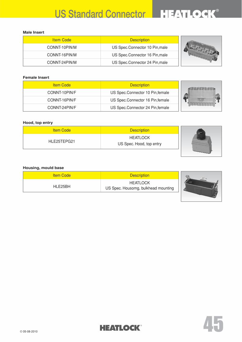
Description
US Spec.Connector 10 Pin,male
US Spec.Connector 16 Pin,male
US Spec.Connector 24 Pin,male
Male Insert
Item Code
CONNT-10PIN/M
CONNT-16PIN/M
CONNT-24PIN/M
Description
US Spec.Connector 10 Pin,female
US Spec.Connector 16 Pin,female
US Spec.Connector 24 Pin,female
Female Insert
Item Code
CONNT-10PIN/F
CONNT-16PIN/F
CONNT-24PIN/F
Description
HEATLOCK
US Spec. Hood, top entry
Hood, top entry
Item Code
HLE25TEPG21
Description
HEATLOCKUS Spec. Housomg, bulkhead mounting
Housing, mould base
Item Code
HLE25BH
US Standard Connector
��
www.heatlock.com
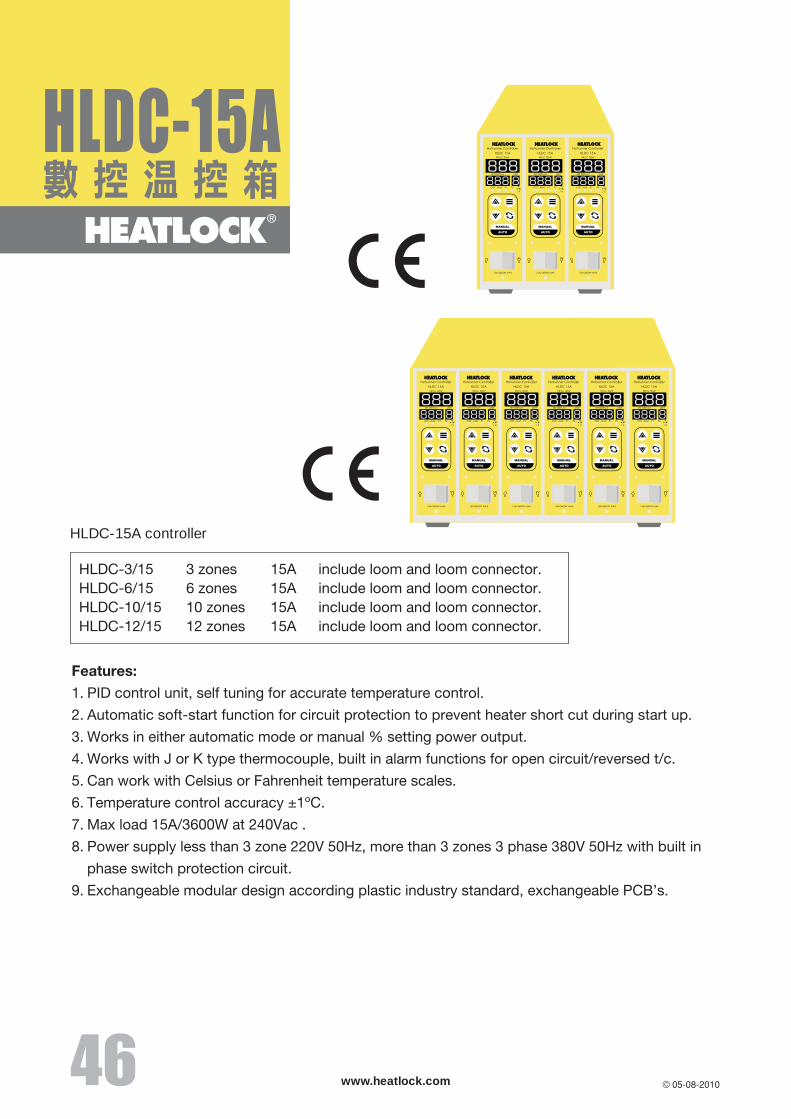
HLDC-15A controller
M1
M2
M3
60/80/150
W
H
60/80/150
W
H
60/80/150
W
H
38
Color or Material Change Necessary: Yes No
(Hot Runner System Department)Changping Tel : (86) 0769-8382 5600 Fax: (86) 0769-8382 5626Hong Kong Tel : (852) 8120 5469 Fax: (852) 3020 1725 Email: [email protected]
www.heatlock.com
Remarks:
HEATLOCK MOULDING SYSTEM QUOTE REQUEST FORM
Customer Quote No:
Company:
Address:
Date:
Contact:
Tel: Fax: E-mail:
Please provide the following information, for quotation
Product Description:
Material:
Glass Filled: %
Frame Retardant
Per Product Weight:
No.of Gates Per Product:
Description of Gate Finish:
No. of Cavities:
Size of Product (L * W * H):
Sprue-gate
Extended Sprue-gate
Ring-gate
Point-gate
Nozzle Length:
Feed Bush
Drawing:
Hot Half: Yes
Thickness of ’A’ Plate:
PP PE PS SB EVA ABS POM SAN PA6
PMMA ASA CAB PBT PA66 PC PC/ABS PPS
PET PES PPO PSU PEEK LCP PEI PVC S/H
Filling the form and fax to us : (86) 0769-8382 5626For detail information, please go to our web : www.heatlock.com
Feed Bush Heater: Yes No
Insulation Plate: Yes
Colour: Transparence
R=
Project Book: Chinese English
Controller: Yes No
��