Embed Size (px)
Citation preview
Heating and Air Conditioning
AFFINITYGEOTHERMAL HEAT PUMPSDUAL-CAPACITY HYDRONIC
MODELS:YAWT100 - 180
Due to continuous product improvement, specifications are subject to change without notice.
Visit us on the web at www.york.com
Additional rating information can found atwww.ahridirectory.org
FOR DISTRIBUTION USE ONLY - NOT TO BE USED AT POINT OF RETAIL SALE
SPECIFICATION CATALOG
YAWT100 - 180(8 THRU 15 NOMINAL TONS)

3
Table of Contents
Model Nomenclature . . . . . . . . . . . . . . . . . . . . . . . . . . . . . . . . . . . . . . . . . . . . . . . . . . . . . . . . . . . . . . 4
AHRI Data . . . . . . . . . . . . . . . . . . . . . . . . . . . . . . . . . . . . . . . . . . . . . . . . . . . . . . . . . . . . . . . . . . . . . 5-6
The Affinity Series. . . . . . . . . . . . . . . . . . . . . . . . . . . . . . . . . . . . . . . . . . . . . . . . . . . . . . . . . . . . . . . . 7-8
Inside the Affinity Series . . . . . . . . . . . . . . . . . . . . . . . . . . . . . . . . . . . . . . . . . . . . . . . . . . . . . . . . . . . . 9
Affinity Series Controls . . . . . . . . . . . . . . . . . . . . . . . . . . . . . . . . . . . . . . . . . . . . . . . . . . . . . . . . . . 10-14
Affinity Series Application Notes. . . . . . . . . . . . . . . . . . . . . . . . . . . . . . . . . . . . . . . . . . . . . . . . . . . 15-21
Flow Rates . . . . . . . . . . . . . . . . . . . . . . . . . . . . . . . . . . . . . . . . . . . . . . . . . . . . . . . . . . . . . . . . . . . . . 22
Water Quality . . . . . . . . . . . . . . . . . . . . . . . . . . . . . . . . . . . . . . . . . . . . . . . . . . . . . . . . . . . . . . . . . . . 23
Affinity Typical Application Piping . . . . . . . . . . . . . . . . . . . . . . . . . . . . . . . . . . . . . . . . . . . . . . . . . . . . 24
Dimensional Data . . . . . . . . . . . . . . . . . . . . . . . . . . . . . . . . . . . . . . . . . . . . . . . . . . . . . . . . . . . . . . . . 25
Physical Data . . . . . . . . . . . . . . . . . . . . . . . . . . . . . . . . . . . . . . . . . . . . . . . . . . . . . . . . . . . . . . . . . . . 26
Electrical Data . . . . . . . . . . . . . . . . . . . . . . . . . . . . . . . . . . . . . . . . . . . . . . . . . . . . . . . . . . . . . . . . . . 26
Antifreeze Correction . . . . . . . . . . . . . . . . . . . . . . . . . . . . . . . . . . . . . . . . . . . . . . . . . . . . . . . . . . . . . 27
Load and Source Pressure Drop . . . . . . . . . . . . . . . . . . . . . . . . . . . . . . . . . . . . . . . . . . . . . . . . . . . . 28
Reference Calculations . . . . . . . . . . . . . . . . . . . . . . . . . . . . . . . . . . . . . . . . . . . . . . . . . . . . . . . . . . . 29
Legend and Notes . . . . . . . . . . . . . . . . . . . . . . . . . . . . . . . . . . . . . . . . . . . . . . . . . . . . . . . . . . . . . . . 29
Performance Data . . . . . . . . . . . . . . . . . . . . . . . . . . . . . . . . . . . . . . . . . . . . . . . . . . . . . . . . . . . . . 30-37
Wiring Schematics . . . . . . . . . . . . . . . . . . . . . . . . . . . . . . . . . . . . . . . . . . . . . . . . . . . . . . . . . . . . . 38-40
Accessories and Options . . . . . . . . . . . . . . . . . . . . . . . . . . . . . . . . . . . . . . . . . . . . . . . . . . . . . . . . 41-43
Engineering Guide Specifications. . . . . . . . . . . . . . . . . . . . . . . . . . . . . . . . . . . . . . . . . . . . . . . . . . 44-45
Revision Guide . . . . . . . . . . . . . . . . . . . . . . . . . . . . . . . . . . . . . . . . . . . . . . . . . . . . . . . . . . . . . . . . . . 46
AFFINITY DUAL CAPACITY HYDRONIC SPECIFICATION CATALOG
4
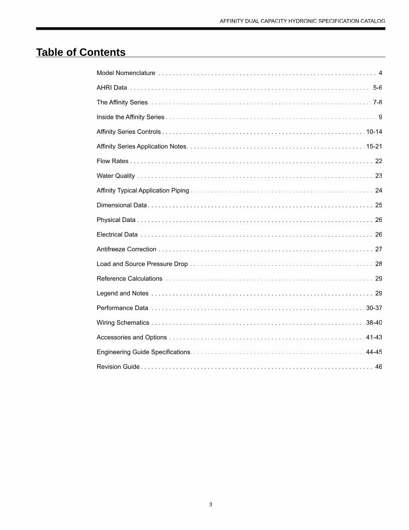
Model Nomenclature
Affinity Series hydronic units are Safety listed under UL1995 thru ETL and performance tested in accordance with standard AHRI/ISO 13256-2.
YAW T 100 T R 1 0 N N S 0 F *1-3 4 4-6 8 9 10 11 12 13 14 15 16 17
ModelYAW – Affinity Water-to-Water
StageT – Dual Capacity
Unit Capacity100, 120, 150, 180
Water ConfigurationT – TopB – Back
OperationR – Reversible
Voltage1 – 208-230/60/1
GeoStart Option0 – No GeoStart3 – GeoStart
Vintage* - Factory Use Only
ControlsF – FX10 with User Interface,
no Communication
Future Options0 – Standard
Future OptionsS – Standard
Water Coil OptionN – Standard
Future OptionN - None
Rev.: 28 May 2013D
AFFINITY DUAL CAPACITY HYDRONIC SPECIFICATION CATALOG
5
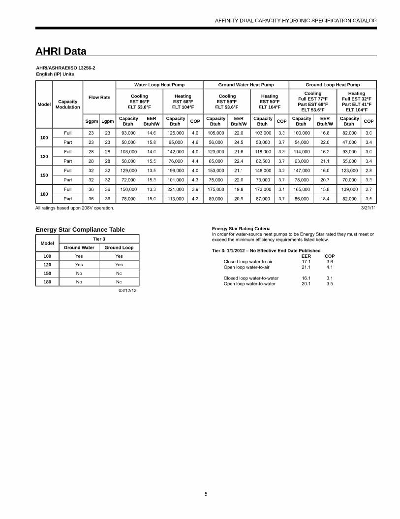
AHRI Data
Energy Star Compliance Table
ModelTier 3
Ground Water Ground Loop
100 Yes Yes
120 Yes Yes
150 No No
180 No No
03/12/13
Energy Star Rating CriteriaIn order for water-source heat pumps to be Energy Star rated they must meet or exceed the minimum efficiency requirements listed below.
Tier 3: 1/1/2012 – No Effective End Date Published EER COP
Closed loop water-to-air 17.1 3.6Open loop water-to-air 21.1 4.1
Closed loop water-to-water 16.1 3.1Open loop water-to-water 20.1 3.5
AHRI/ASHRAE/ISO 13256-2English (IP) Units
Model CapacityModulation
Flow Rate
Water Loop Heat Pump Ground Water Heat Pump Ground Loop Heat Pump
CoolingEST 86°F
ELT 53.6°F
HeatingEST 68°F ELT 104°F
CoolingEST 59°F
ELT 53.6°F
Heating EST 50°F ELT 104°F
CoolingFull EST 77°F Part EST 68°F
ELT 53.6°F
Heating Full EST 32°F Part ELT 41°F
ELT 104°F
Sgpm Lgpm CapacityBtuh
EERBtuh/W
CapacityBtuh COP Capacity
BtuhEER
Btuh/W Capacity
Btuh COP CapacityBtuh
EERBtuh/W
CapacityBtuh COP
100Full 23 23 93,000 14.6 125,000 4.0 105,000 22.0 103,000 3.3 100,000 16.8 82,000 3.0
Part 23 23 50,000 15.8 65,000 4.6 56,000 24.5 53,000 3.7 54,000 22.0 47,000 3.4
120Full 28 28 103,000 14.0 142,000 4.0 123,000 21.6 118,000 3.3 114,000 16.2 93,000 3.0
Part 28 28 58,000 15.5 76,000 4.4 65,000 22.4 62,500 3.7 63,000 21.1 55,000 3.4
150Full 32 32 129,000 13.5 199,000 4.0 153,000 21.1 148,000 3.2 147,000 16.0 123,000 2.8
Part 32 32 72,000 15.3 101,000 4.3 75,000 22.0 73,000 3.7 78,000 20.7 70,000 3.3
180Full 36 36 150,000 13.3 221,000 3.9 175,000 19.8 173,000 3.1 165,000 15.8 139,000 2.7
Part 36 36 78,000 15.0 113,000 4.2 89,000 20.9 87,000 3.7 86,000 18.4 82,000 3.5
3/21/11All ratings based upon 208V operation.
AFFINITY DUAL CAPACITY HYDRONIC SPECIFICATION CATALOG
6
The performance standard AHRI/ASHRAE/ISO 13256-2 became effective January 1, 2000. This new standard has three major categories:Water Loop, Ground Water, and Ground Loop.Unit of Measure: The Cooling COP
The cooling efficiency is measured in EER (US version measured in Btuh per Watt. The Metric version is measured in a cooling COP (Watt per Watt) similar to the traditional COP measurement.
Pump Power Correction CalculationWithin each model, only one water flow rate is specified for all three groups and pumping Watts are calculated using the followingformula. This additional power is added onto the existing power consumption.• Pump power correction = (gpm x 0.0631) x (Press Drop x 2990) / 300Where ‘gpm’ is waterflow in gpm and ‘Press Drop’ is the pressure drop through the unit heat exchanger at rated water flow in feetof head.
ISO Capacity and Efficiency CalculationsThe following equations illustrate cooling calculations:• ISO Cooling Capacity = Cooling Capacity (Btuh) x 3.412• ISO EER Efficiency (W/W) = ISO Cooling Capacity (Btuh) x 3.412 / [Power Input (Watts) + Pump Power Correction (Watt)]The following equations illustrate heating calculations:• ISO Heating Capacity = Heating Capacity (Btuh) x 3.412• ISO COP Efficiency (W/W) = ISO Heating Capacity (Btuh) x 3.412 / [Power Input (Watts) + Pump Power Correction (Watt)]
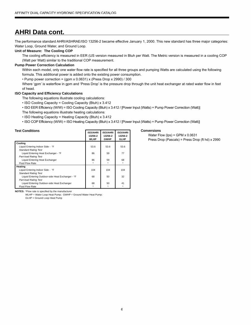
Test Conditions
AHRI Data cont.
ISO/AHRI13256-2WLHP
ISO/AHRI13256-2GWHP
ISO/AHRI13256-2GLHP
Cooling Liquid Entering Indoor Side - °F Standard Rating Test Liquid Entering Heat Exchanger - °F Part-load Rating Test Liquid Entering Heat Exchanger Fluid Flow RateHeating Liquid Entering Indoor Side - °F Standard Rating Test Liquid Entering Outdoor-side Heat Exchanger - °F Part-load Rating Test Liquid Entering Outdoor-side Heat Exchanger Fluid Flow Rate
53.6
86
86*
104
68
68*
53.6
59
59*
104
50
50*
53.6
77
68*
104
32
41*
NOTES: *Flow rate is specified by the manufacturer WLHP = Water Loop Heat Pump; GWHP = Ground Water Heat Pump; GLHP = Ground Loop Heat Pump
Conversions Water Flow (lps) = GPM x 0.0631 Press Drop (Pascals) = Press Drop (ft hd) x 2990
AFFINITY DUAL CAPACITY HYDRONIC SPECIFICATION CATALOG
7
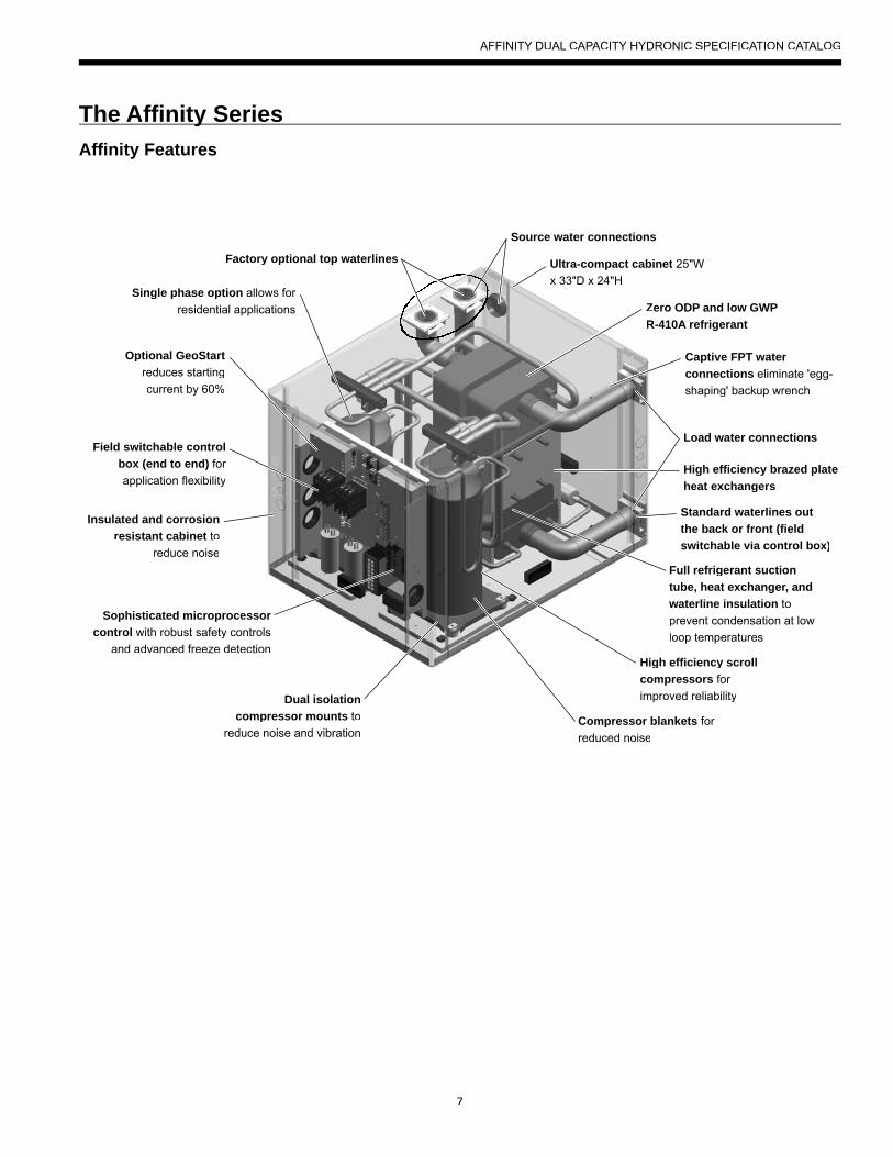
The Affi nity Seriesy
Factory optional top waterlinesry optional top waterlines
Optional GeoStartreduces startingcurrent by 60%
Field switchable controlbox (end to end) for application flexibility
Insulated and corrosionresistant cabinet to
reduce noise
Sophisticated microprocessoor control with robust safety controols
and advanced freeze detectioon
Full refrigerant suctiontube, heat exchanger, and waterline insulation to prevent condensation at lowloop temperatures
High efficiency brazed plate heat exchangers
Captive FPT water connections eliminate 'egg-shaping' backup wrench
Single phase option alloows for residential appliccations
Ultra-compact cabinet Ultra-compact cab 25"Wx 33"D x 24"H
Zero ODP and low GWP ZR-410A refrigerantR
gh efficiency scrollHicompressors for improved reliability
Compressor blankets for reduced noise
Dual isolation compressor mounts to
reduce noise and vibration
Standard waterlines out the back or front (fieldswitchable via control box)
Source water connections
Load water connections
Affinity Features
AFFINITY DUAL CAPACITY HYDRONIC SPECIFICATION CATALOG
8
High Efficiency The Affinity Series are the highest efficiency units available. Large oversized water to refrigerant heat exchangers and scroll compressorsprovide extremely efficient operation. This efficiency means the Affinity Series requires less loop than any product on the market. This can mean significant savings on commercial and residential projects.
Standard Features• Single phase is available. • Heavy gauge cabinet• Quiet scroll compressors in all models• Two-dimension refrigerant piping vibration loops to isolate
the compressor.• All interior cabinet surfaces are insulated with 1/2˝ [12.7mm]
thick 1-1/2lb [681g] density, surface coated, acoustic type glass fiber insulation.
• Optional GeoStart to reduce starting current• Field switchable control box• Advanced FX10 control• Ultra-compact cabinet• Optional top or back mounted water lines
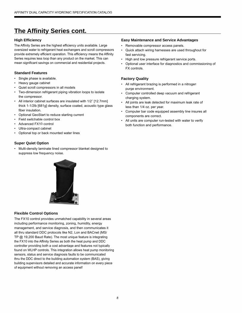
Super Quiet Option• Multi-density laminate lined compressor blanket designed to
suppress low frequency noise.
Flexible Control OptionsThe FX10 control provides unmatched capability in several areasincluding performance monitoring, zoning, humidity, energy management, and service diagnosis, and then communicates it all thru standard DDC protocols like N2, Lon and BACnet (MS/TP @ 19,200 Baud Rate). The most unique feature is integratingthe FX10 into the Affinity Series as both the heat pump and DDC controller providing both a cost advantage and features not typicallyfound on WLHP controls. This integration allows heat pump monitoringsensors, status and service diagnosis faults to be communicatedthru the DDC direct to the building automation system (BAS), givingbuilding supervisors detailed and accurate information on every pieceof equipment without removing an access panel!
Easy Maintenance and Service Advantages• Removable compressor access panels.• Quick attach wiring harnesses are used throughout for
fast servicing.• High and low pressure refrigerant service ports.• Optional user interface for diagnostics and commissioning of
FX controls.
Factory Quality• All refrigerant brazing is performed in a nitrogen
purge environment. • Computer controlled deep vacuum and refrigerant
charging system.• All joints are leak detected for maximum leak rate of
less than 1/4 oz. per year.• Computer bar code equipped assembly line insures all
components are correct.• All units are computer run-tested with water to verify
both function and performance.
The Affi nity Series cont.y
AFFINITY DUAL CAPACITY HYDRONIC SPECIFICATION CATALOG
9
Inside the Affi nity SeriesyRefrigerantAffinity Series products all feature zero ozone depletion and low global warming potential R-410A refrigerant.
CabinetAll units are constructed of corrosion resistant galvanized sheet metal with silver metallic powder coat paint rated for more than1000 hours of salt spray. Large lift-out access panels provide access to the compressor section from four sides. Back or topwater connection option is available.
CompressorsHigh efficiency R-410A scroll compressors are used on everymodel. Scrolls provide both the highest efficiency available andgreat reliability.
Electrical BoxUnit controls feature quick connect wiring harnesses for easyservicing. Separate knockouts for low voltage, and two for power on two sides allow easy access to the control box. A large 75VA transformer assures adequate control's power for accessories.Flexible Johnson Controls FX10 microprocessor control is included,featuring several innovations. See Affinity Series Controls section for more information.
Water ConnectionsFlush mount FPT water connection fittings allow one wrench leak-freeconnections and do not require a backup wrench. Factory installedthermistors are used on all water lines and can be viewed through themicroprocessor interface tool.
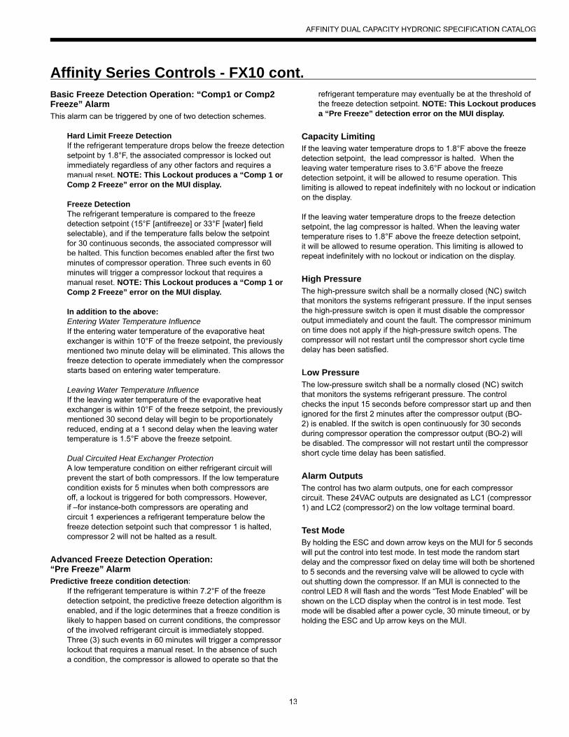
Thermostatic Expansion ValveAll Affinity Series models utilize a balancedport bi-directional thermostatic expansionvalve (TXV) for refrigerant metering. Thisallows precise refrigerant flow in a widerange of entering water variation (30 to 120°F [-1.1 to 49°C]) found in geothermalsystems. The TXV is located in the compressor compartment for easy access.
Water-to-Refrigerant Heat ExchangerLarge oversized stainless steel interlacedcopper-brazed plate water-to-refrigerant heatexchangers provide unparalleled efficiency. The heat exchangers have common water circuits wiisolated refrigerant circuits so that in part load operation, the full mass of the heat exchanger isutilized. All heat exchangers are pressure ratedto 450 psi water side and 650 psi refrigerant sideAll heat exchangers, water lines, and suction lineare insulated to prevent condensation during lowtemperature inlet water operation.
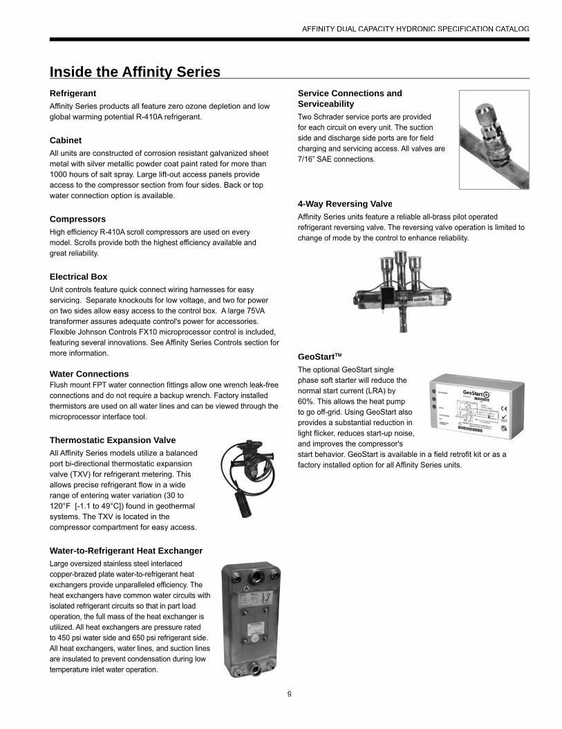
Service Connections and ServiceabilityTwo Schrader service ports are providedfor each circuit on every unit. The suctionside and discharge side ports are for fieldcharging and servicing access. All valves are7/16” SAE connections.
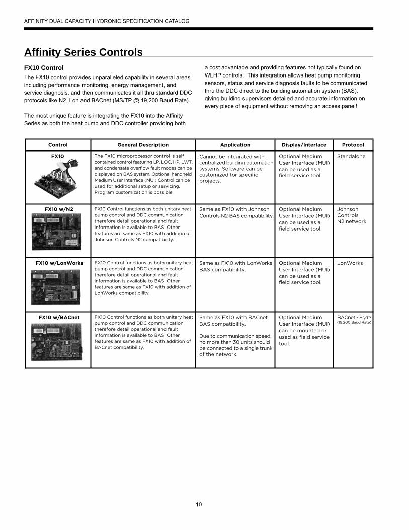
4-Way Reversing ValveAffinity Series units feature a reliable all-brass pilot operatedrefrigerant reversing valve. The reversing valve operation is limited tochange of mode by the control to enhance reliability.
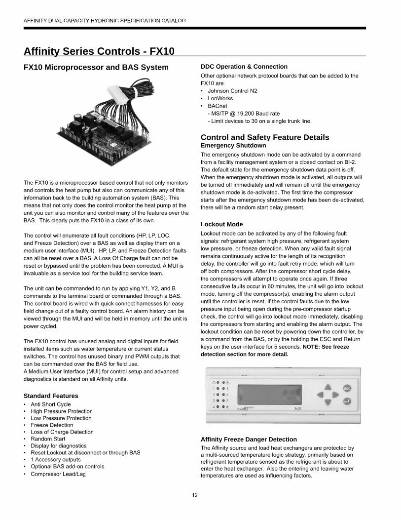
GeoStartTM
The optional GeoStart singlephase soft starter will reduce the normal start current (LRA) by60%. This allows the heat pump to go off-grid. Using GeoStart alsoprovides a substantial reduction inlight flicker, reduces start-up noise, and improves the compressor's start behavior. GeoStart is available in a field retrofit kit or as afactory installed option for all Affinity Series units.
ith
e. esw
AFFINITY DUAL CAPACITY HYDRONIC SPECIFICATION CATALOG
10
FX10 ControlThe FX10 control provides unparalleled capability in several areasincluding performance monitoring, energy management, andservice diagnosis, and then communicates it all thru standard DDCprotocols like N2, Lon and BACnet (MS/TP @ 19,200 Baud Rate).
The most unique feature is integrating the FX10 into the AffinitySeries as both the heat pump and DDC controller providing both
a cost advantage and providing features not typically found on WLHP controls. This integration allows heat pump monitoring sensors, status and service diagnosis faults to be communicatedthru the DDC direct to the building automation system (BAS),giving building supervisors detailed and accurate information onevery piece of equipment without removing an access panel!
Control General Description Application Display/Interface Protocol
The FX10 microprocessor control is self contained control featuring LP, LOC, HP, LWT, and condensate overflow fault modes can be displayed on BAS system. Optional handheld Medium User Interface (MUI) Control can be used for additional setup or servicing.Program customization is possible.
Cannot be integrated withcentralized building automationsystems. Software can becustomized for specificprojects.
Optional Medium User Interface (MUI) can be used as afield service tool.
Standalone
FX10 Control functions as both unitary heat pump control and DDC communication, therefore detail operational and fault information is available to BAS. Other features are same as FX10 with addition of Johnson Controls N2 compatibility.
Same as FX10 with Johnson Controls N2 BAS compatibility.
Optional Medium User Interface (MUI) can be used as afield service tool.
JohnsonControlsN2 network
FX10 Control functions as both unitary heat pump control and DDC communication, therefore detail operational and fault information is available to BAS. Other features are same as FX10 with addition of LonWorks compatibility.
Same as FX10 with LonWorks BAS compatibility.
Optional Medium User Interface (MUI) can be used as afield service tool.
LonWorks
FX10 Control functions as both unitary heat pump control and DDC communication, therefore detail operational and fault information is available to BAS. Other features are same as FX10 with addition of BACnet compatibility.
Same as FX10 with BACnet BAS compatibility.
Due to communication speed,no more than 30 units shouldbe connected to a single trunkof the network.
Optional Medium User Interface (MUI) can be mounted or used as field service tool.
BACnet - MS/TP(19,200 Baud Rate)
FX10
FX10 w/N2
FX10 w/LonWorks
FX10 w/BACnet
Affi nity Series Controlsy
AFFINITY DUAL CAPACITY HYDRONIC SPECIFICATION CATALOG

11
FX10 Advanced Control Overview• The Johnson Controls FX10 board is specifically designed for
commercial heat pumps and provides control of the entire unitas well as input ports for Open N2, LonTalk, BACnet (MS/TP @ 19,200 Baud Rate) communication protocols as well as aninput port for a user interface. The user interface can be used to aid in diagnostics and unit setup and is standard on all Affinityunits. A 16-pin low voltage terminal board provides terminals for common field connections. The FX10 Control provides:
• Operational sequencing• High and low-pressure switch monitoring• General lockout• Advanced Freeze Detection Temperature Sensing• Lockout mode control • Emergency shutdown mode • Random start and short cycle protection
Short Cycle ProtectionAllows a minimum compressor “off” time of five minutes and a minimum “on” time of two minutes.
Random StartA delay of 1 to 120 seconds is generated after each power- up to prevent simultaneous startup of all units within a building after the release from an unoccupied cycle or power loss.
Emergency Shutdown A field-applied dry contact can be used to place the control into emergency shutdown mode. During this mode, all outputs on theboard are disabled.
Freeze Detection Temperature Limit Field selectable for 15°F or 33°F (-9.4° or 0.6°C)
Installation Options• Standalone controlled by an aquastat• Integrated into BAS by adding communication module
Accessory Outputs Quantity 1. Cycled with the compressor. Field selectable for normally open (factory default) or normally closed through thebuilding automation system or user interface.
User Interface4 x 20 backlit LCD
Optional Plug-in Communication Modules -(compatible with standard BAS protocols)• Open N2• LonTalk• BACnet (MS/TP @ 19,200 Baud Rate)
Display One local display is standard on all Affinity units. Up to 2 displays, either 1 local and 1 remote, or 2 remote. (A 2-display configurationrequires identical displays.) Local display can be up to 3 meters from the controller, power supply, and data communication. Remote display can be up to 300 meters from the controller.Remote display must be independently powered with data communication done via 3 pole shielded cable.
Control Timing & Fault Recognition DelaysLead compressor “ON” delay ............................................90 seconds (not applicable for single compressor models)Minimum compressor “ON” time ...........................................2 minutes (except for fault condition)Short cycle delay ..................................................................5 minutesRandom start delay ......................................................0-120 secondsHigh pressure fault ............................................................. <1 secondLow pressure fault .............................................................30 secondsFreeze detection fault .....................................................0-30 secondsLow pressure fault bypass ....................................................2 minutes
Affi nity Series Controls - FX10y
Mainn FX 10 Board
AFFINITY DUAL CAPACITY HYDRONIC SPECIFICATION CATALOG
12
FX10 Microprocessor and BAS System
The FX10 is a microprocessor based control that not only monitorsand controls the heat pump but also can communicate any of this information back to the building automation system (BAS). This means that not only does the control monitor the heat pump at the unit you can also monitor and control many of the features over theBAS. This clearly puts the FX10 in a class of its own.
The control will enumerate all fault conditions (HP, LP, LOC, and Freeze Detection) over a BAS as well as display them on amedium user interface (MUI). HP, LP, and Freeze Detection faults can all be reset over a BAS. A Loss Of Charge fault can not be reset or bypassed until the problem has been corrected. A MUI is invaluable as a service tool for the building service team.
The unit can be commanded to run by applying Y1, Y2, and B commands to the terminal board or commanded through a BAS.The control board is wired with quick connect harnesses for easy field change out of a faulty control board. An alarm history can be viewed through the MUI and will be held in memory until the unit ispower cycled.
The FX10 control has unused analog and digital inputs for field installed items such as water temperature or current statusswitches. The control has unused binary and PWM outputs that can be commanded over the BAS for field use.A Medium User Interface (MUI) for control setup and advanced diagnostics is standard on all Affinity units.
Standard Features• Anti Short Cycle• High Pressure Protection• Low Pressure Protection• Freeze Detection• Loss of Charge Detection• Random Start• Display for diagnostics• Reset Lockout at disconnect or through BAS• 1 Accessory outputs• Optional BAS add-on controls• Compressor Lead/Lag
DDC Operation & ConnectionOther optional network protocol boards that can be added to theFX10 are:• Johnson Control N2• LonWorks• BACnet - MS/TP @ 19,200 Baud rate - Limit devices to 30 on a single trunk line.
Control and Safety Feature DetailsEmergency ShutdownThe emergency shutdown mode can be activated by a commandfrom a facility management system or a closed contact on BI-2.The default state for the emergency shutdown data point is off.When the emergency shutdown mode is activated, all outputs willbe turned off immediately and will remain off until the emergencyshutdown mode is de-activated. The first time the compressor starts after the emergency shutdown mode has been de-activated, there will be a random start delay present.
Lockout ModeLockout mode can be activated by any of the following faultsignals: refrigerant system high pressure, refrigerant systemlow pressure, or freeze detection. When any valid fault signalremains continuously active for the length of its recognitiondelay, the controller will go into fault retry mode, which will turn off both compressors. After the compressor short cycle delay,the compressors will attempt to operate once again. If three consecutive faults occur in 60 minutes, the unit will go into lockout mode, turning off the compressor(s), enabling the alarm outputuntil the controller is reset. If the control faults due to the low pressure input being open during the pre-compressor startup check, the control will go into lockout mode immediately, disabling the compressors from starting and enabling the alarm output. The lockout condition can be reset by powering down the controller, by a command from the BAS, or by the holding the ESC and Return keys on the user interface for 5 seconds. NOTE: See freezedetection section for more detail.
Affinity Freeze Danger DetectionThe Affinity source and load heat exchangers are protected by a multi-sourced temperature logic strategy, primarily based on refrigerant temperature sensed as the refrigerant is about toenter the heat exchanger. Also the entering and leaving water temperatures are used as influencing factors.
Affi nity Series Controls - FX10y
AFFINITY DUAL CAPACITY HYDRONIC SPECIFICATION CATALOG
13
Basic Freeze Detection Operation: “Comp1 or Comp2Freeze” AlarmThis alarm can be triggered by one of two detection schemes.
Hard Limit Freeze DetectionIf the refrigerant temperature drops below the freeze detection setpoint by 1.8°F, the associated compressor is locked outimmediately regardless of any other factors and requires amanual reset. NOTE: This Lockout produces a “Comp 1 or Comp 2 Freeze” error on the MUI display.
Freeze DetectionThe refrigerant temperature is compared to the freezedetection setpoint (15°F [antifreeze] or 33°F [water] fieldselectable), and if the temperature falls below the setpoint for 30 continuous seconds, the associated compressor will be halted. This function becomes enabled after the first two minutes of compressor operation. Three such events in 60minutes will trigger a compressor lockout that requires a manual reset. NOTE: This Lockout produces a “Comp 1 or Comp 2 Freeze” error on the MUI display.
In addition to the above: Entering Water Temperature InfluenceIf the entering water temperature of the evaporative heatexchanger is within 10°F of the freeze setpoint, the previouslymentioned two minute delay will be eliminated. This allows thefreeze detection to operate immediately when the compressor starts based on entering water temperature.
Leaving Water Temperature InfluenceIf the leaving water temperature of the evaporative heatexchanger is within 10°F of the freeze setpoint, the previouslymentioned 30 second delay will begin to be proportionatelyreduced, ending at a 1 second delay when the leaving water temperature is 1.5°F above the freeze setpoint.
Dual Circuited Heat Exchanger ProtectionA low temperature condition on either refrigerant circuit willprevent the start of both compressors. If the low temperaturecondition exists for 5 minutes when both compressors are off, a lockout is triggered for both compressors. However,if –for instance-both compressors are operating and circuit 1 experiences a refrigerant temperature below the freeze detection setpoint such that compressor 1 is halted,compressor 2 will not be halted as a result.
Advanced Freeze Detection Operation:“Pre Freeze” AlarmPredictive freeze condition detection:
If the refrigerant temperature is within 7.2°F of the freezedetection setpoint, the predictive freeze detection algorithm is enabled, and if the logic determines that a freeze condition is likely to happen based on current conditions, the compressor of the involved refrigerant circuit is immediately stopped.Three (3) such events in 60 minutes will trigger a compressor lockout that requires a manual reset. In the absence of such a condition, the compressor is allowed to operate so that the
refrigerant temperature may eventually be at the threshold of the freeze detection setpoint. NOTE: This Lockout produces a “Pre Freeze” detection error on the MUI display.
Capacity LimitingIf the leaving water temperature drops to 1.8°F above the freeze detection setpoint, the lead compressor is halted. When theleaving water temperature rises to 3.6°F above the freezedetection setpoint, it will be allowed to resume operation. Thislimiting is allowed to repeat indefinitely with no lockout or indication on the display.
If the leaving water temperature drops to the freeze detection setpoint, the lag compressor is halted. When the leaving water temperature rises to 1.8°F above the freeze detection setpoint, it will be allowed to resume operation. This limiting is allowed torepeat indefinitely with no lockout or indication on the display.
High PressureThe high-pressure switch shall be a normally closed (NC) switch that monitors the systems refrigerant pressure. If the input sensesthe high-pressure switch is open it must disable the compressor output immediately and count the fault. The compressor minimumon time does not apply if the high-pressure switch opens. Thecompressor will not restart until the compressor short cycle timedelay has been satisfied.
Low PressureThe low-pressure switch shall be a normally closed (NC) switch that monitors the systems refrigerant pressure. The control checks the input 15 seconds before compressor start up and thenignored for the first 2 minutes after the compressor output (BO-2) is enabled. If the switch is open continuously for 30 secondsduring compressor operation the compressor output (BO-2) willbe disabled. The compressor will not restart until the compressor short cycle time delay has been satisfied.
Alarm OutputsThe control has two alarm outputs, one for each compressor circuit. These 24VAC outputs are designated as LC1 (compressor 1) and LC2 (compressor2) on the low voltage terminal board.
Test ModeBy holding the ESC and down arrow keys on the MUI for 5 seconds will put the control into test mode. In test mode the random start delay and the compressor fixed on delay time will both be shortened to 5 seconds and the reversing valve will be allowed to cycle with out shutting down the compressor. If an MUI is connected to thecontrol LED 8 will flash and the words “Test Mode Enabled” will be shown on the LCD display when the control is in test mode. Test mode will be disabled after a power cycle, 30 minute timeout, or byholding the ESC and Up arrow keys on the MUI.
Affi nity Series Controls - FX10 cont.y
AFFINITY DUAL CAPACITY HYDRONIC SPECIFICATION CATALOG

14
Sequence of OperationPower Fail RestartWhen the controller is first powered up, the outputs will bedisabled for a random start delay. The delay is provided to preventsimultaneous starting of multiple heat pumps. Once the timer expires, the controller will operate normally.
Random Start DelayThis delay will be used after every power failure, as well as the first time the compressor is started after the control exitsthe unoccupied mode or the emergency shutdown mode. The delay should not be less than 1 second and not longer than 120 seconds. If the control is in test mode the random start delay will be shortened to 5 seconds.
Lead Compressor Start Delay TimeThe Lead Compressor Fixed On Delay Time will ensure thatthe lead compressor output is not enabled for 90 seconds after the control receives a call to start the compressor. This delay is adjustable from 30 – 300 seconds over a BAS or a MUI. If the control is in test mode the Lead Compressor Start Delay Timer will be shortened to 5 seconds.
Lag Compressor Start Delay TimeThe Lag Compressor Fixed On Delay Time will ensure that the lag compressor output is not enabled for 120 seconds after the control receives a call to start the compressor. If the control is intest mode the Lag Compressor Start Delay Timer will be shortenedto 5 seconds.
Compressor Minimum On DelayThe compressor minimum on delay will ensure that the compressor output is enabled for a minimum of two (2) minutes each time the compressor output is enabled. This will apply inevery instance except in the event the high pressure switch is tripped or emergency shutdown then the compressor output will be disable immediately.
Compressor Minimum Off Delay TimeThe compressor minimum time delay will ensure that the compressor output will not be enabled for a minimum of five (5) minutes after it is disabled. This allows for the system refrigerant pressures to equalize after the compressor is disabled.
Compressor Lead/LagCompressor lead/lag is a standard part of the FX10 controlsystem. The unit is shipped from the factory with lead/lag enabled.Lead/lag can be activated through the unit mounted user interface. Lead/lag will always start the compressor with the least amount of runtime and stop the compressor with the longest runtime.
Heating CycleThe control will position the reversing valve for heating mode whenthere is no command on the O/B terminal on the terminal board. The compressor will be commanded by Y1 and Y2.
Cooling CycleThe control will position the reversing valve for cooling mode whenthere is a command on the O/B terminal on the terminal board. The compressor will be commanded by Y1 and Y2.
MUI Alarm History ReportingIf a fault occurs the fault will be recorded in history for display onthe medium user interface in the History Menu. Each fault type willbe displayed in the history menu with a number between 0 and 3.A reading of 3+ will mean that fault has occurred more than three times in the past. The history menu can be cleared with a power cycle only. Alarm date and time are not included in the history.
Inputs and Outputs ConfigurationField Selectable Options
Load and Source Freeze Detection SetpointThe freeze detection setpoint input allows you to adjust thefreeze detection setpoint for either the load or source sidesof the heat pump. When the jumper is installed on BI-5 theload freeze detection setpoint is factory set for 33°F. When the jumper on BI-5 is removed the load freeze detectionsetpoint will be 15°F. When the jumper is installed on BI-4 the source freeze detection setpoint is factory set for 33°F. Whenthe jumper on BI-4 is removed the source freeze detectionsetpoint will be 15°F. NOTE: Piping circuit must be antifreeze protected to the set levels or the warranty will be voided.
Accessory OutputThe Accessory Output will be energized 90 seconds prior to the lead compressor output being energized. When bothcompressor outputs are turned off the accessory output will be deactivated immediately. This output is selectable for normallyopen or normally closed operation through the Medium User Interface or through the Building Automation System.
Control Accessories• A99 Sensor• MUI (LCD User interface) for diagnostics and commissioning• MUIK3 - Panel Mount, Portable• MUIK4 - Wall Mount
Affi nity Series Controls - FX10 cont.y
AFFINITY DUAL CAPACITY HYDRONIC SPECIFICATION CATALOG
15
The Closed Loop Heat Pump ConceptThe basic principle of a water source heat pump is the transfer of heat into water from the space during cooling, or the transfer of heat from water into the space during heating. Extremely highlevels of energy efficiency are achieved as electricity is used onlyto move heat, not to produce it. Using a typical Affinity Series, one unit of electricity will move four to five units of heat.
When multiple water source heat pumps are combined on acommon circulating loop, the ultimate in energy efficiency iscreated: Our geothermal units on cooling mode are adding heat to the loop which the units in heating mode can absorb, thusremoving heat from the area where cooling is needed, recovering and redistributing that heat for possible utilization elsewhere inthe system. In modern commercial structures, this characteristicof heat recovery from core area heat generated by lighting, officeequipment, computers, solar radiation, people or other sources, is an important factor in the high efficiency and low operating costs of our closed source heat pump systems.
In the event that a building's net heating and cooling requirementscreate loop temperature extremes, Affinity Series units have the extended range capacity and versatility to maintain a comfortableenvironment for all building areas. Excess heat can be storedfor later utilization or be added or removed in one of three ways;by ground-source heat exchanger loops: plate heat exchangersconnected to other water sources, or conventional cooler/boiler configurations. Your representative has the expertise and computer software to assist in determining optimum system typefor specific applications.
The Closed Loop AdvantageA properly applied water source heat pump system offers many advantages over other systems. First costs are low because units can be added to the loop on an "as needed basis"- perfectfor speculative buildings. Installed costs are low since units are self-contained and can be located adjacent to the occupied space, requiring minimal ductwork. Maintenance can be done
on individual units without system shut-down. Conditions remaincomfortable since each unit operates separately, allowing cooling in one area and heating in another. Tenant spaces can befinished and added as needed. Power billing to tenants is alsoconvenient since each unit can be individually metered: each paysfor what each uses. Nighttime and/or weekend uses of certainareas are possible without heating or cooling the entire facility.A decentralized system also means if one unit should fault, the rest of the system will continue to operate normally, as well as eliminating air cross-contamination problems and expensive high pressure duct systems requiring an inefficient electric resistancereheat mode.
Affinity Series ApproachThere are a number of proven choices in the type of Affinity Series system which would be best for any given application. Most oftenconsidered are:
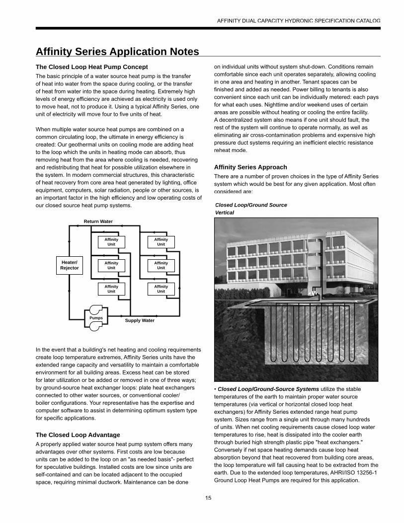
• Closed Loop/Ground-Source Systems utilize the stabletemperatures of the earth to maintain proper water sourcetemperatures (via vertical or horizontal closed loop heat exchangers) for Affinity Series extended range heat pump system. Sizes range from a single unit through many hundreds of units. When net cooling requirements cause closed loop water temperatures to rise, heat is dissipated into the cooler earth through buried high strength plastic pipe "heat exchangers."Conversely if net space heating demands cause loop heatabsorption beyond that heat recovered from building core areas,the loop temperature will fall causing heat to be extracted from theearth. Due to the extended loop temperatures, AHRI/ISO 13256-1 Ground Loop Heat Pumps are required for this application.
Affi nity Series Application Notesy pp
Supply Water
Return Water
Pumps
AffinityUnit
AffinityUnit
AffinityUnit
AffinityUnit
AffinityUnit
AffinityUnit
Heater/Rejector
Closed Loop/Ground SourceVertical
AFFINITY DUAL CAPACITY HYDRONIC SPECIFICATION CATALOG
16
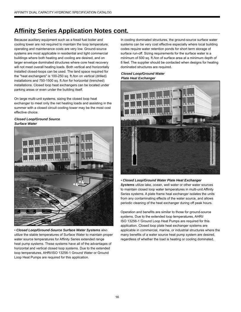
In cooling dominated structures, the ground-source surface water systems can be very cost effective especially where local buildingcodes require water retention ponds for short term storage of surface run-off. Sizing requirements for the surface water is aminimum of 500 sq. ft./ton of surface area at a minimum depth of 8 feet. The supplier should be contacted when designs for heating dominated structures are required.
• Closed Loop/Ground Water Plate Heat ExchangerSystems utilize lake, ocean, well water or other water sourcesto maintain closed loop water temperatures in multi-unit Affinity Series systems. A plate frame heal exchanger isolates the units from any contaminating effects of the water source, and allows periodic cleaning of the heat exchanger during off peak hours.
Operation and benefits are similar to those for ground-source systems. Due to the extended loop temperatures, AHRI/ISO 13256-1 Ground Loop Heat Pumps are required for this application. Closed loop plate heat exchanger systems are applicable in commercial, marine, or industrial structures where themany benefits of a water source heat pump system are desired, regardless of whether the load is heating or cooling dominated.
Because auxiliary equipment such as a fossil fuel boiler and cooling tower are not required to maintain the loop temperature,operating and maintenance costs are very low. Ground-source systems are most applicable in residential and light commercial buildings where both heating and cooling are desired, and onlarger envelope dominated structures where core heat recovery will not meet overall heating loads. Both vertical and horizontallyinstalled closed-loops can be used. The land space required for the "heat exchangers" is 100-250 sq. ft./ton on vertical (drilled) installations and 750-1500 sq. ft./ton for horizontal (trenched) installations. Closed loop heat exchangers can be located under parking areas or even under the building itself.
On large multi-unit systems, sizing the closed loop heatexchanger to meet only the net heating loads and assisting in thesummer with a closed circuit cooling tower may be the most costeffective choice.
• Closed Loop/Ground-Source Surface Water Systems alsoutilize the stable temperatures of Surface Water to maintain proper water source temperatures for Affinity Series extended rangeheat pump systems. These systems have all of the advantages of horizontal and vertical closed loop systems. Due to the extendedloop temperatures, AHRI/ISO 13256-1 Ground Water or GroundLoop Heat Pumps are required for this application.
Affi nity Series Application Notes cont.y pp
Closed Loop/Ground SourceSurface Water
Closed Loop/Ground WaterPlate Heat Exchanger
AFFINITY DUAL CAPACITY HYDRONIC SPECIFICATION CATALOG
17
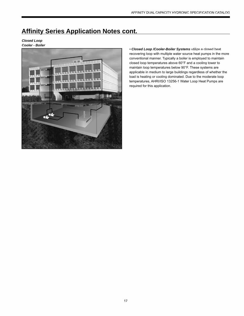
Affi nity Series Application Notes cont.y ppClosed LoopCooler - Boiler
• Closed Loop /Cooler-Boiler Systems utilize a closed heat recovering loop with multiple water source heat pumps in the moreconventional manner. Typically a boiler is employed to maintain closed loop temperatures above 60°F and a cooling tower to maintain loop temperatures below 90°F. These systems areapplicable in medium to large buildings regardless of whether the load is heating or cooling dominated. Due to the moderate looptemperatures, AHRI/ISO 13256-1 Water Loop Heat Pumps arerequired for this application.
AFFINITY DUAL CAPACITY HYDRONIC SPECIFICATION CATALOG
18
Heating with hot water is versatile because there are many waysof distributing the heat through the building. The options rangefrom heavy cast iron radiators seen in older buildings to modern,baseboard-style convection radiation, and from invisible radiant floor heating to forced air systems using fan coil units.
A boiler is often used to make domestic hot water and to heat swimming pools or hot tubs.
The various distribution systems have all been used successfully with a geothermal heat pump system. When designing or retrofitting an existing hydronic heating system, however, the water temperature produced by the heat pump is a major consideration.
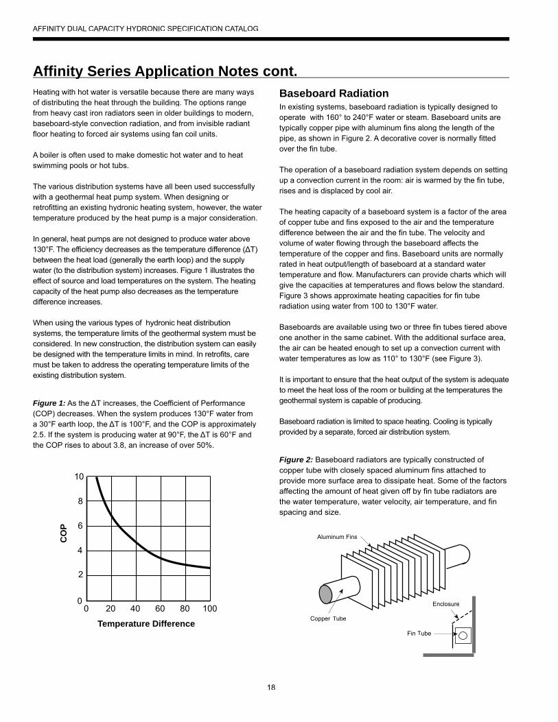
In general, heat pumps are not designed to produce water above130°F. The efficiency decreases as the temperature difference (ΔT)between the heat load (generally the earth loop) and the supplywater (to the distribution system) increases. Figure 1 illustrates the effect of source and load temperatures on the system. The heatingcapacity of the heat pump also decreases as the temperaturedifference increases.
When using the various types of hydronic heat distribution systems, the temperature limits of the geothermal system must be considered. In new construction, the distribution system can easily be designed with the temperature limits in mind. In retrofits, caremust be taken to address the operating temperature limits of the existing distribution system.
Figure 1: As the ΔT increases, the Coefficient of Performance(COP) decreases. When the system produces 130°F water froma 30°F earth loop, the ΔT is 100°F, and the COP is approximately 2.5. If the system is producing water at 90°F, the ΔT is 60°F and the COP rises to about 3.8, an increase of over 50%.
Figure 2: Baseboard radiators are typically constructed of copper tube with closely spaced aluminum fins attached toprovide more surface area to dissipate heat. Some of the factors affecting the amount of heat given off by fin tube radiators are the water temperature, water velocity, air temperature, and fin spacing and size.
Baseboard RadiationIn existing systems, baseboard radiation is typically designed to operate with 160° to 240°F water or steam. Baseboard units are typically copper pipe with aluminum fins along the length of thepipe, as shown in Figure 2. A decorative cover is normally fittedover the fin tube.
The operation of a baseboard radiation system depends on setting up a convection current in the room: air is warmed by the fin tube, rises and is displaced by cool air.
The heating capacity of a baseboard system is a factor of the area of copper tube and fins exposed to the air and the temperature difference between the air and the fin tube. The velocity and volume of water flowing through the baseboard affects thetemperature of the copper and fins. Baseboard units are normallyrated in heat output/length of baseboard at a standard water temperature and flow. Manufacturers can provide charts which will give the capacities at temperatures and flows below the standard.Figure 3 shows approximate heating capacities for fin tuberadiation using water from 100 to 130°F water.
Baseboards are available using two or three fin tubes tiered aboveone another in the same cabinet. With the additional surface area, the air can be heated enough to set up a convection current with water temperatures as low as 110° to 130°F (see Figure 3).
It is important to ensure that the heat output of the system is adequate to meet the heat loss of the room or building at the temperatures thegeothermal system is capable of producing.
Baseboard radiation is limited to space heating. Cooling is typically provided by a separate, forced air distribution system.
Temperature Difference
0 20 40 60 80 100
CO
P
2
4
6
8
10
0
Aluminum Fins
Enclosure
Fin Tube
Copper Tube
Affi nity Series Application Notes cont.y pp
AFFINITY DUAL CAPACITY HYDRONIC SPECIFICATION CATALOG
19
The heating capacity (Btuh/linear foot) of baseboard radiators drop as the water temperature is reduced. The heating capacityof most baseboard radiators is rated using 200°F water, 65°F air temperature. Listed in Figure 3 is the range of heating capacities of baseboard radiators at the standard temperatures and therange of capacities when the temperatures are reduced to theoperating range of a heat pump system. Some of the factors that affect the capacity of a radiator are:• Size of the fins - range from 2.75 in. x 3 in. to 4 in. x 4 in.• Fin spacing - 24 to 48/foot• Diameter of copper tube - range from .75 in. to 2 in.• Fin material - aluminum or steel• Configuration and height of the enclosure• Height unit is mounted from the floor• Water flow through the radiator
Generally, the smaller fins with fewer fins/foot will have lower heating capacity. Larger copper tube diameter and aluminum fins will have a higher capacity. Higher water flow will increasecapacity. Adding a second fin tube to the same enclosure will increase the capacity by 50 to 60%. Adding two fin tubes willincrease the capacity by 75 to 80%.
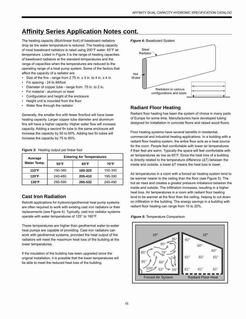
Cast Iron RadiationRetrofit applications for hydronic/geothermal heat pump systems are often required to work with existing cast iron radiators or their replacements (see Figure 4). Typically, cast iron radiator systemsoperate with water temperatures of 125° to 160°F.
These temperatures are higher than geothermal water-to-water heat pumps are capable of providing. Cast iron radiators canwork with geothermal systems, provided the heat output of theradiators will meet the maximum heat loss of the building at thelower temperatures.
If the insulation of the building has been upgraded since theoriginal installation, it is possible that the lower temperatures willbe able to meet the reduced heat loss of the building.
AverageWater Temp.
Entering Air Temperatures
55°F 65°F 70°F
110°F 190-380 160-320 150-300
120°F 240-480 205-410 195-390
130°F 295-590 265-532 245-490
Figure 3: Heating output per linear foot
Radiant Floor HeatingRadiant floor heating has been the system of choice in many partsof Europe for some time. Manufacturers have developed tubingdesigned for installation in concrete floors and raised wood floors.
Floor heating systems have several benefits in residential,commercial and industrial heating applications. In a building with aradiant floor heating system, the entire floor acts as a heat sourcefor the room. People feel comfortable with lower air temperaturesif their feet are warm. Typically the space will feel comfortable with air temperatures as low as 65°F. Since the heat loss of a buildingis directly related to the temperature difference (ΔT) between the inside and outside, a lower ΔT means the heat loss is lower.
Air temperatures in a room with a forced air heating system tend tobe warmer nearer to the ceiling than the floor (see Figure 5). The hot air rises and creates a greater pressure imbalance between the inside and outside. The infiltration increases, resulting in a higher heat loss. Air temperatures in a room with radiant floor heating tend to be warmer at the floor than the ceiling, helping to cut downon infiltration in the building. The energy savings in a building with radiant floor heating can range from 10 to 20%.
SteelRadiator
HotWater
Radiators in variousconfigurations and sizes
Figure 4: Baseboard System
Figure 5: Temperature Comparison
10° 10°
85°
95°
79°
68°
63° 81° 81° 81°
65° 65° 65°
60°60°
60°
Forced Air System Radiant Floor Heat
95°90°
74°
100° 59°
Affi nity Series Application Notes cont.y pp
AFFINITY DUAL CAPACITY HYDRONIC SPECIFICATION CATALOG
20
A floor heat system can be designed to heat a building with water temperatures as low as 90°F.
Figure 1 shows how a geothermal system operates more efficientlywith a lower ΔT between the source and the load. With only a60°F temperature difference, a geothermal heat pump will operate at COPs over 4, about 20% higher than a forced air geothermal system in the same installation.
Some of the factors affecting the heating capacity of a floor heatingsystem are as follows:• The type of finish flooring• The spacing of the pipe• The water flow through the pipe• The temperature of the supply water• The floor material (wood, concrete or poured Gypcrete™)• Insulation value under the floor• The piping layout
The spacing of the pipe in residential applications canvary from 4 in. to 12 in. If the spacing is too large, the temperature of the floor can vary noticeably. In industrial applications, variationin the floor temperature is not as important, and the spacing isrelated directly to the heat output required.
Radiant floor heating systems work well with geothermal heatpump systems. For efficient operation, the system must be designed with the lowest possible water temperatures.
There are some drawbacks with a radiant floor heating system. Air conditioning is only possible by adding a second system using forced air. This can add substantial cost to an installation whereair conditioning is also needed. A separate air handling system is needed to clean the air or to introduce fresh air.
Industrial buildings, especially those with high ceilings and large overhead doors, have an advantage with a radiant floor heating system. Heat is stored in the concrete floor, and when a door is opened, the stored heat is immediately released to the space. The larger the ΔT between the air in the space and the floor, the quicker the floor releases its heat to the space.
Maintenance garages benefit from radiant floor heating systems. Cold vehicles brought into the garage are warmed from underneath. The snow melts off the vehicle and dries much morequickly than when heated from above.
Some pipe manufacturers include an oxygen diffusion barrier in the pipe to prevent oxygen diffusion through thepipe. Good system design and careful installation, however, will eliminate virtually all of the problems encounteredwith air in the system. Like earth loop design, it is important todesign the system to facilitate flushing the air initially and ensuringthat the flows can be balanced properly.
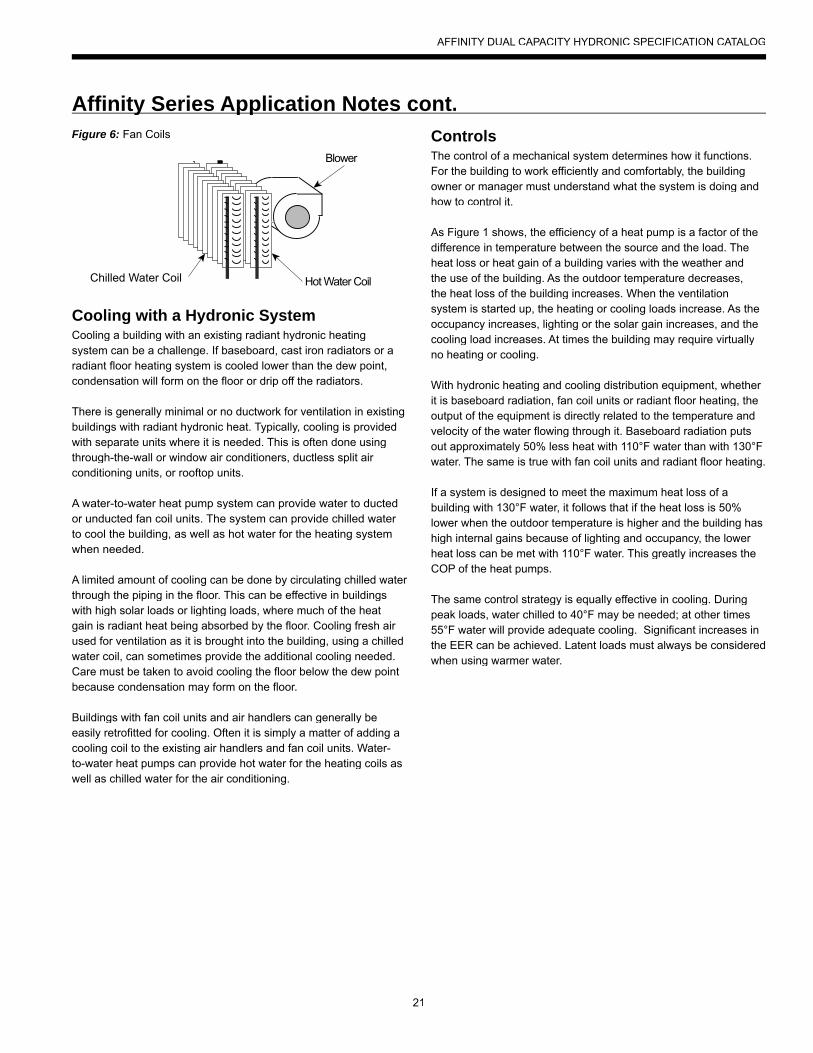
Fan Coil Units and Air HandlersFan coil units, air handlers, force flow units, etc. are all basicallya hot water radiator or coil (usually copper piping with aluminum fins) with a fan or blower to move the air over the coil (see Figure6). The term “fan coil units” typically applies to smaller units that are installed in the zone or area in which heating (or cooling)is needed. They are available in many different configurations, sizes and capacities. Fan coil units are designed to be connectedto a ductwork system and can be used to replace a forced air furnace. Other units are designed for use without ductwork andare mounted in a suspended ceiling space with only a grill showingin place of a ceiling tile. Some can be mounted on a wall under awindow, projecting 8 in. to 10 in. into the room or even flush to thewall surface, mounted between wall studs. Some are available with or without finished, decorative cabinets. For industrial applications,inexpensive “unit heaters” are available, with only a coil and an axial fan. Fan coil units and unit heaters are normally available with air handling capacities of 200 to 2,000 cfm.
The term “air handler” normally applies to larger units, mounted in mechanical rooms, mechanical crawl spaces or rooftops. Theytypically have an air handling capacity of over 2,000 cfm andare available for capacities of up to 50,000 cfm. Air handlers aretypically built for a specific installation and are available with many different types of heating and cooling coils. They can includeadditional coils for heating make-up air, dehumidification and exhaust air heat recovery.
Fan coils and air handlers typically have one or two coils and ablower. Air is heated by hot water circulated through the hot water coil. Chilled water is circulated through the coil if air conditioning is needed. Blowers can be provided to fit various applications,with or without duct-work. Unit heaters typically use axial fans inapplications where ductwork is not needed.
Fan coil units and air handlers are used in many different applications. They have been used to heat buildings using water temperatures as low as 90° to 100°F. New systems can be designed to operate very efficiently with a geothermal system.
Affi nity Series Application Notes cont.y pp
AFFINITY DUAL CAPACITY HYDRONIC SPECIFICATION CATALOG
21
Cooling with a Hydronic SystemCooling a building with an existing radiant hydronic heatingsystem can be a challenge. If baseboard, cast iron radiators or a radiant floor heating system is cooled lower than the dew point, condensation will form on the floor or drip off the radiators.
There is generally minimal or no ductwork for ventilation in existing buildings with radiant hydronic heat. Typically, cooling is providedwith separate units where it is needed. This is often done usingthrough-the-wall or window air conditioners, ductless split air conditioning units, or rooftop units.
A water-to-water heat pump system can provide water to ducted or unducted fan coil units. The system can provide chilled water to cool the building, as well as hot water for the heating systemwhen needed.
A limited amount of cooling can be done by circulating chilled water through the piping in the floor. This can be effective in buildingswith high solar loads or lighting loads, where much of the heat gain is radiant heat being absorbed by the floor. Cooling fresh air used for ventilation as it is brought into the building, using a chilledwater coil, can sometimes provide the additional cooling needed.Care must be taken to avoid cooling the floor below the dew pointbecause condensation may form on the floor.
Buildings with fan coil units and air handlers can generally be easily retrofitted for cooling. Often it is simply a matter of adding acooling coil to the existing air handlers and fan coil units. Water-to-water heat pumps can provide hot water for the heating coils aswell as chilled water for the air conditioning.
Hot Water Coil
Blower
Chilled Water Coil
Figure 6: Fan Coils ControlsThe control of a mechanical system determines how it functions. For the building to work efficiently and comfortably, the building owner or manager must understand what the system is doing and how to control it.
As Figure 1 shows, the efficiency of a heat pump is a factor of thedifference in temperature between the source and the load. The heat loss or heat gain of a building varies with the weather and the use of the building. As the outdoor temperature decreases, the heat loss of the building increases. When the ventilation system is started up, the heating or cooling loads increase. As theoccupancy increases, lighting or the solar gain increases, and thecooling load increases. At times the building may require virtually no heating or cooling.
With hydronic heating and cooling distribution equipment, whether it is baseboard radiation, fan coil units or radiant floor heating, theoutput of the equipment is directly related to the temperature and velocity of the water flowing through it. Baseboard radiation puts out approximately 50% less heat with 110°F water than with 130°Fwater. The same is true with fan coil units and radiant floor heating.
If a system is designed to meet the maximum heat loss of abuilding with 130°F water, it follows that if the heat loss is 50%lower when the outdoor temperature is higher and the building hashigh internal gains because of lighting and occupancy, the lower heat loss can be met with 110°F water. This greatly increases the COP of the heat pumps.
The same control strategy is equally effective in cooling. During peak loads, water chilled to 40°F may be needed; at other times 55°F water will provide adequate cooling. Significant increases inthe EER can be achieved. Latent loads must always be considered when using warmer water.
Affi nity Series Application Notes cont.y pp
AFFINITY DUAL CAPACITY HYDRONIC SPECIFICATION CATALOG
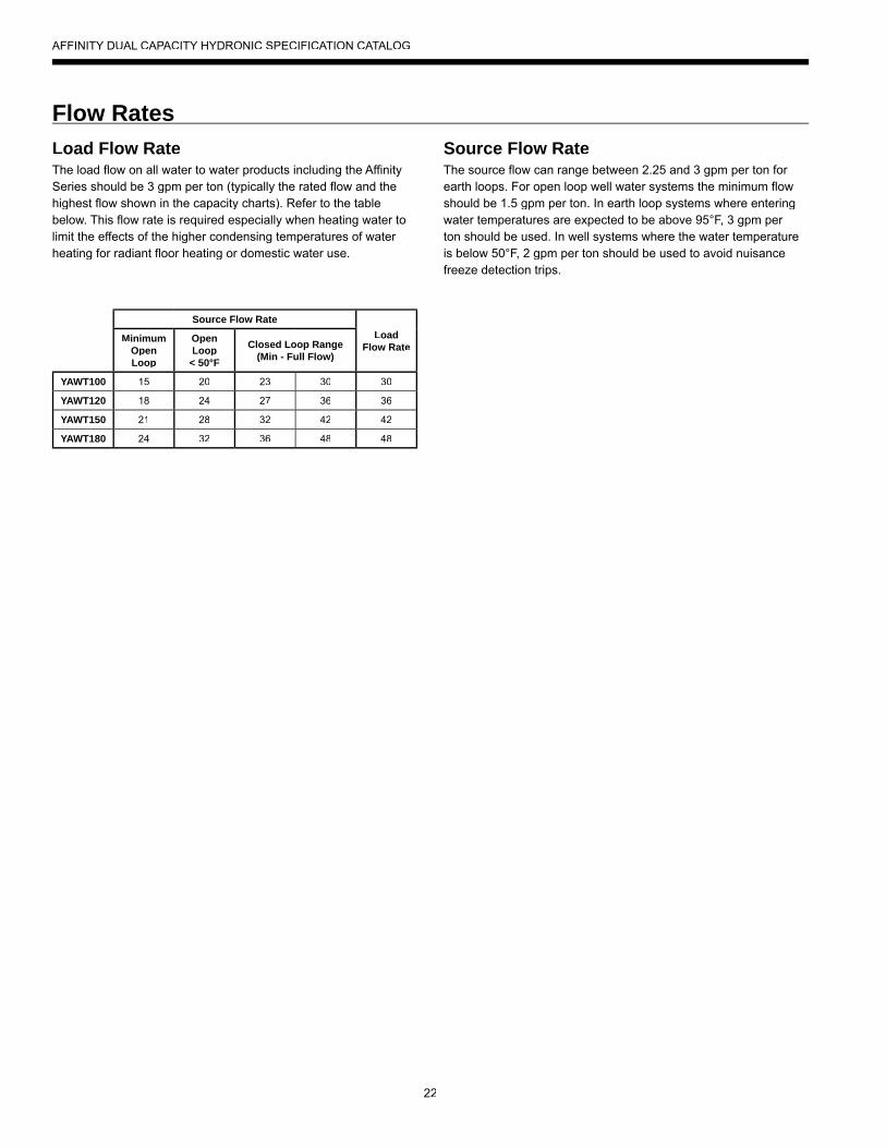
22
Load Flow RateThe load flow on all water to water products including the Affinity Series should be 3 gpm per ton (typically the rated flow and the highest flow shown in the capacity charts). Refer to the table below. This flow rate is required especially when heating water to limit the effects of the higher condensing temperatures of water heating for radiant floor heating or domestic water use.
Source Flow RateThe source flow can range between 2.25 and 3 gpm per ton for earth loops. For open loop well water systems the minimum flowshould be 1.5 gpm per ton. In earth loop systems where enteringwater temperatures are expected to be above 95°F, 3 gpm per ton should be used. In well systems where the water temperatureis below 50°F, 2 gpm per ton should be used to avoid nuisancefreeze detection trips.
Flow Rates
Source Flow RateLoad
Flow RateMinimum
Open Loop
OpenLoop < 50°F
Closed Loop Range(Min - Full Flow)
YAWT100 15 20 23 30 30
YAWT120 18 24 27 36 36
YAWT150 21 28 32 42 42
YAWT180 24 32 36 48 48
AFFINITY DUAL CAPACITY HYDRONIC SPECIFICATION CATALOG
23
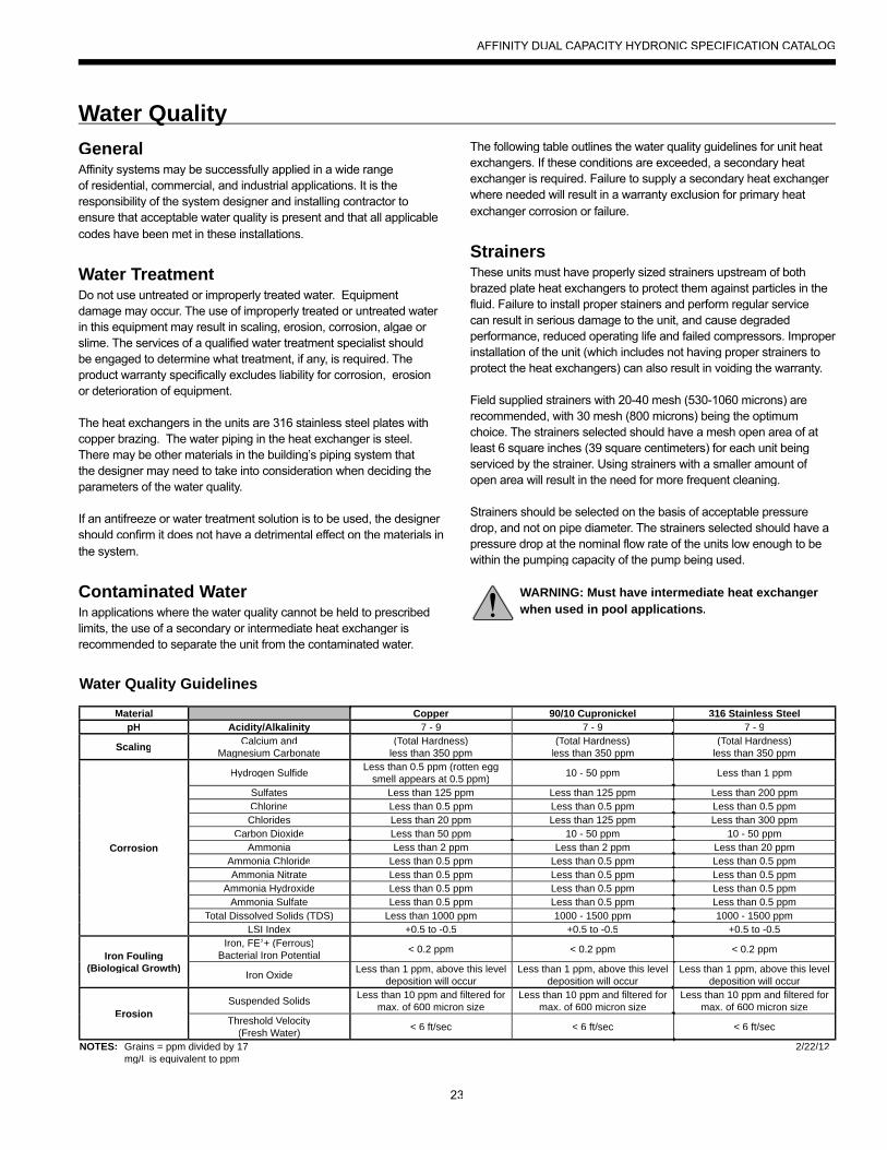
GeneralAffinity systems may be successfully applied in a wide range of residential, commercial, and industrial applications. It is theresponsibility of the system designer and installing contractor to ensure that acceptable water quality is present and that all applicable codes have been met in these installations.
Water TreatmentDo not use untreated or improperly treated water. Equipment damage may occur. The use of improperly treated or untreated water in this equipment may result in scaling, erosion, corrosion, algae or slime. The services of a qualified water treatment specialist shouldbe engaged to determine what treatment, if any, is required. Theproduct warranty specifically excludes liability for corrosion, erosion or deterioration of equipment.
The heat exchangers in the units are 316 stainless steel plates with copper brazing. The water piping in the heat exchanger is steel.There may be other materials in the building’s piping system that the designer may need to take into consideration when deciding the parameters of the water quality.
If an antifreeze or water treatment solution is to be used, the designer should confirm it does not have a detrimental effect on the materials in the system.
Contaminated WaterIn applications where the water quality cannot be held to prescribedlimits, the use of a secondary or intermediate heat exchanger is recommended to separate the unit from the contaminated water.
Material Copper 90/10 Cupronickel 316 Stainless SteelpH Acidity/Alkalinity 7 - 9 7 - 9 7 - 9
Scaling Calcium andMagnesium Carbonate
(Total Hardness)TTless than 350 ppm
(Total Hardness)TTless than 350 ppm
(Total Hardness)TTless than 350 ppm
Corrosion
Hydrogen Sulfide Less than 0.5 ppm (rotten eggsmell appears at 0.5 ppm) 10 - 50 ppm Less than 1 ppm
Sulfates Less than 125 ppm Less than 125 ppm Less than 200 ppmChlorine Less than 0.5 ppm Less than 0.5 ppm Less than 0.5 ppmChlorides Less than 20 ppm Less than 125 ppm Less than 300 ppm
Carbon Dioxide Less than 50 ppm 10 - 50 ppm 10 - 50 ppmAmmonia Less than 2 ppm Less than 2 ppm Less than 20 ppm
Ammonia Chloride Less than 0.5 ppm Less than 0.5 ppm Less than 0.5 ppmAmmonia Nitrate Less than 0.5 ppm Less than 0.5 ppm Less than 0.5 ppm
Ammonia Hydroxide Less than 0.5 ppm Less than 0.5 ppm Less than 0.5 ppmAmmonia Sulfate Less than 0.5 ppm Less than 0.5 ppm Less than 0.5 ppm
Total Dissolved Solids (TDS)TT Less than 1000 ppm 1000 - 1500 ppm 1000 - 1500 ppmLSI Index +0.5 to -0.5 +0.5 to -0.5 +0.5 to -0.5
Iron Fouling(Biological Growth)
Iron, FE2+ (Ferrous)Bacterial Iron Potential < 0.2 ppm < 0.2 ppm < 0.2 ppm
Iron Oxide Less than 1 ppm, above this level deposition will occur
Less than 1 ppm, above this level deposition will occur
Less than 1 ppm, above this leveldeposition will occur
ErosionSuspended Solids Less than 10 ppm and filtered for
max. of 600 micron sizeLess than 10 ppm and filtered for
max. of 600 micron sizeLess than 10 ppm and filtered for
max. of 600 micron sizeThreshold VelocityVV
(Fresh Water) < 6 ft/sec < 6 ft/sec < 6 ft/sec
NOTES: Grains = ppm divided by 17mg/L is equivalent to ppmL
2/22/12
Water QualityyThe following table outlines the water quality guidelines for unit heatexchangers. If these conditions are exceeded, a secondary heatexchanger is required. Failure to supply a secondary heat exchanger where needed will result in a warranty exclusion for primary heat exchanger corrosion or failure.
StrainersThese units must have properly sized strainers upstream of both brazed plate heat exchangers to protect them against particles in thefluid. Failure to install proper stainers and perform regular service can result in serious damage to the unit, and cause degraded performance, reduced operating life and failed compressors. Improper installation of the unit (which includes not having proper strainers to protect the heat exchangers) can also result in voiding the warranty.
Field supplied strainers with 20-40 mesh (530-1060 microns) arerecommended, with 30 mesh (800 microns) being the optimumchoice. The strainers selected should have a mesh open area of at least 6 square inches (39 square centimeters) for each unit beingserviced by the strainer. Using strainers with a smaller amount of open area will result in the need for more frequent cleaning.
Strainers should be selected on the basis of acceptable pressure drop, and not on pipe diameter. The strainers selected should have apressure drop at the nominal flow rate of the units low enough to bewithin the pumping capacity of the pump being used.
WARNING: Must have intermediate heat exchanger when used in pool applications.
Water Quality Guidelines
AFFINITY DUAL CAPACITY HYDRONIC SPECIFICATION CATALOG
24
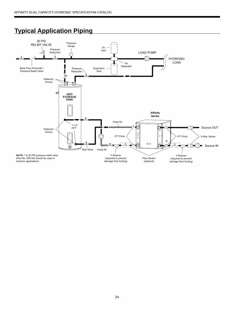
Typical Application Pipingyp pp p g
LOAD PUMP
HYDRONICLOAD
Source OUT
P/T Ports
Ball Valve
DielectricUnions
DielectricUnions
NOTE: * A 30 PSI pressure relief valve(Part No: SRV30) should be used inhydronic applications.
1-1/2˝FPT
ExpansionTank
AirVent
PressureGauge
30 PSIRELIEF VALVE
AirSeparator
Back Flow Preventer /Pressure Relief Valve
GEOSTORAGE
TANK
3-Way Valves
Y-Strainer(required to prevent
damage from fouling)
Hose Kit
PressureReduction
PressureReduction
Hose Kit
P/T Ports
Source IN
Y-Strainer(required to prevent
damage from fouling)Flow Switch
(optional)
AffinitySeries
AFFINITY DUAL CAPACITY HYDRONIC SPECIFICATION CATALOG
25
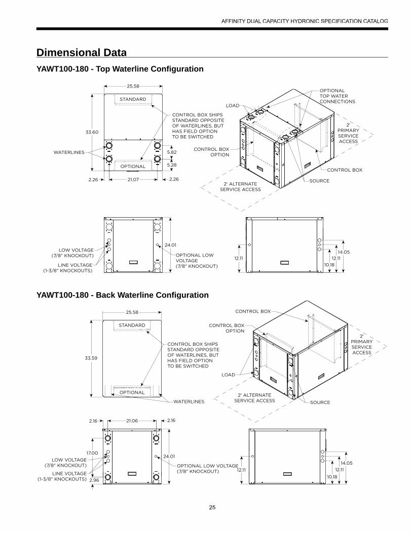
Dimensional DataYAWT100-180 - Top Waterline Configuration
YAWT100-180 - Back Waterline Configuration
AFFINITY DUAL CAPACITY HYDRONIC SPECIFICATION CATALOG
26
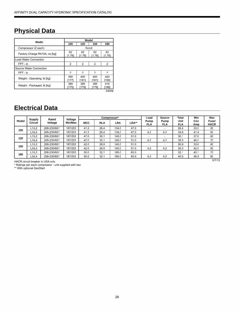
Physical Datay
Electrical Data
Model Model100 120 150 180
Compressor (2 each) Scroll
Factory Charge R410A, oz [kg] 62 [1.76]
62 [1.76]
62 [1.76]
62 [1.76]
Load Water Connection FPT - in 2 2 2 2Source Water Connection FPT - in 2 2 2 2
Weight - Operating, lb [kg] 390 [177]
400[181]
400[181]
420[190]
Weight - Packaged, lb [kg] 385 [175]
395[179]
395[179]
415[188]3/9/09
Model Supply Circuit
RatedVoltage
VoltageMin/Max
Compressor* LoadPumpFLA
SourcePumpFLA
TotalUnitFLA
MinCircAmp
MaxFuse/HACRMCC RLA LRA LRA**
100L1/L2 208-230/60/1 187/253 41.2 26.4 134.0 47.0 - - 26.4 33.0 50L3/L4 208-230/60/1 187/253 41.2 26.4 134.0 47.0 4.2 4.2 34.8 41.4 60
120L1/L2 208-230/60/1 187/253 47.0 30.1 145.0 51.0 - - 30.1 37.6 60L3/L4 208-230/60/1 187/253 47.0 30.1 145.0 51.0 4.2 4.2 38.5 46.0 70
150L1/L2 208-230/60/1 187/253 42.0 26.9 145.0 51.0 - - 26.9 33.6 60L3/L4 208-230/60/1 187/253 42.0 26.9 145.0 51.0 4.2 4.2 35.3 42.0 60
180L1/L2 208-230/60/1 187/253 50.0 32.1 185.0 65.0 - - 32.1 40.1 70L3/L4 208-230/60/1 187/253 50.0 32.1 185.0 65.0 4.2 4.2 40.5 48.5 80
3/7/13HACR circuit breaker in USA only* Ratings per each compressor - unit supplied with two** With optional GeoStart
AFFINITY DUAL CAPACITY HYDRONIC SPECIFICATION CATALOG
27
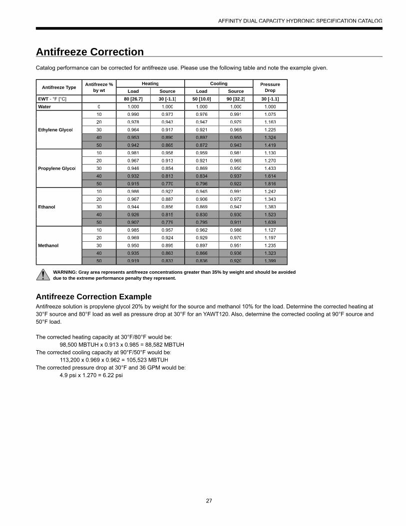
Antifreeze CorrectionCatalog performance can be corrected for antifreeze use. Please use the following table and note the example given.
Antifreeze Correction ExampleAntifreeze solution is propylene glycol 20% by weight for the source and methanol 10% for the load. Determine the corrected heating at 30°F source and 80°F load as well as pressure drop at 30°F for an YAWT120. Also, determine the corrected cooling at 90°F source and50°F load.
The corrected heating capacity at 30°F/80°F would be: 98,500 MBTUH x 0.913 x 0.985 = 88,582 MBTUHThe corrected cooling capacity at 90°F/50°F would be: 113,200 x 0.969 x 0.962 = 105,523 MBTUHThe corrected pressure drop at 30°F and 36 GPM would be: 4.9 psi x 1.270 = 6.22 psi
Antifreeze Type Antifreeze %by wt
Heating Cooling Pressure DropLoad Source Load Source
EWT - °F [°C] 80 [26.7] 30 [-1.1] 50 [10.0] 90 [32.2] 30 [-1.1]Water 0 1.000 1.000 1.000 1.000 1.000
Ethylene Glycol
10 0.990 0.973 0.976 0.991 1.07520 0.978 0.943 0.947 0.979 1.16330 0.964 0.917 0.921 0.965 1.22540 0.953 0.890 0.897 0.955 1.32450 0.942 0.865 0.872 0.943 1.419
Propylene Glycol
10 0.981 0.958 0.959 0.981 1.13020 0.967 0.913 0.921 0.969 1.27030 0.946 0.854 0.869 0.950 1.43340 0.932 0.813 0.834 0.937 1.61450 0.915 0.770 0.796 0.922 1.816
Ethanol
10 0.986 0.927 0.945 0.991 1.24220 0.967 0.887 0.906 0.972 1.34330 0.944 0.856 0.869 0.947 1.38340 0.926 0.815 0.830 0.930 1.52350 0.907 0.779 0.795 0.911 1.639
Methanol
10 0.985 0.957 0.962 0.986 1.12720 0.969 0.924 0.929 0.970 1.19730 0.950 0.895 0.897 0.951 1.23540 0.935 0.863 0.866 0.936 1.32350 0.919 0.833 0.836 0.920 1.399
WARNING: Gray area represents antifreeze concentrations greater than 35% by weight and should be avoideddue to the extreme performance penalty they represent.
AFFINITY DUAL CAPACITY HYDRONIC SPECIFICATION CATALOG
28
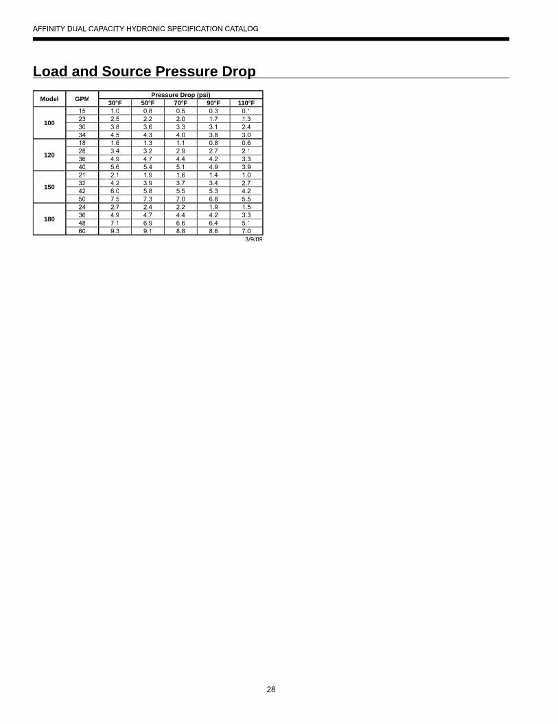
Load and Source Pressure DroppModel GPM Pressure Drop (psi)p (p )
30°F 50°F 70°F 90°F 110°F
100
15 1.0 0.8 0.5 0.3 0.123 2.5 2.2 2.0 1.7 1.330 3.8 3.6 3.3 3.1 2.434 4.5 4.3 4.0 3.8 3.0
120
18 1.6 1.3 1.1 0.8 0.628 3.4 3.2 2.9 2.7 2.136 4.9 4.7 4.4 4.2 3.340 5.6 5.4 5.1 4.9 3.9
150
21 2.1 1.9 1.6 1.4 1.032 4.2 3.9 3.7 3.4 2.742 6.0 5.8 5.5 5.3 4.250 7.5 7.3 7.0 6.8 5.5
180
24 2.7 2.4 2.2 1.9 1.536 4.9 4.7 4.4 4.2 3.348 7.1 6.9 6.6 6.4 5.160 9.3 9.1 8.8 8.6 7.0
3/9/09
AFFINITY DUAL CAPACITY HYDRONIC SPECIFICATION CATALOG
29
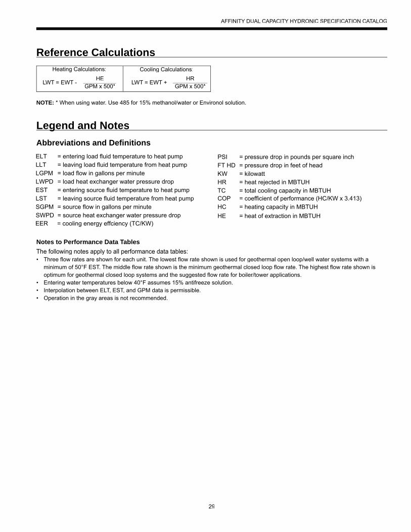
HEGPM x 500*
Legend and NotesgAbbreviations and Definitions
Reference CalculationsHeating Calculations: Cooling Calculations:
LWT = EWT + HR
GPM x 500*LWT = EWT -
NOTE: * When using water. Use 485 for 15% methanol/water or Environol solution.
ELT = entering load fluid temperature to heat pump
EER = cooling energy effciency (TC/KW)
LLT = leaving load fluid temperature from heat pump
PSI = pressure drop in pounds per square inch
LGPM = load flow in gallons per minuteFT HD = pressure drop in feet of head
LWPD = load heat exchanger water pressure dropKW = kilowatt
EST = entering source fluid temperature to heat pump
HR = heat rejected in MBTUH
LST = leaving source fluid temperature from heat pumpTC = total cooling capacity in MBTUH
SGPM = source flow in gallons per minuteCOP = coefficient of performance (HC/KW x 3.413)
SWPD = source heat exchanger water pressure dropHC = heating capacity in MBTUHHE = heat of extraction in MBTUH
Notes to Performance Data TablesThe following notes apply to all performance data tables:• Three flow rates are shown for each unit. The lowest flow rate shown is used for geothermal open loop/well water systems with a minimum of 50°F EST. The middle flow rate shown is the minimum geothermal closed loop flow rate. The highest flow rate shown is optimum for geothermal closed loop systems and the suggested flow rate for boiler/tower applications.• Entering water temperatures below 40°F assumes 15% antifreeze solution. • Interpolation between ELT, EST, and GPM data is permissible. • Operation in the gray areas is not recommended.
AFFINITY DUAL CAPACITY HYDRONIC SPECIFICATION CATALOG
30
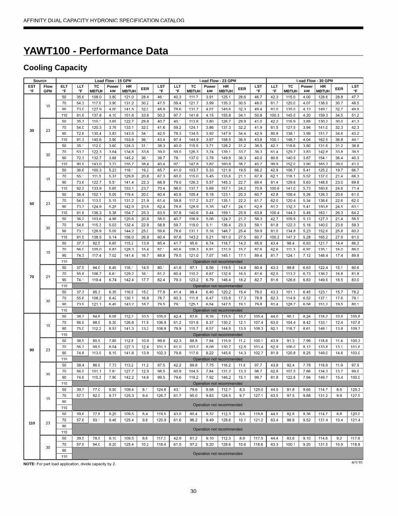
NOTE: For part load application, divide capacity by 2.
YAWT100 - Performance Data
AFFINITY DUAL CAPACITY HYDRONIC SPECIFICATION CATALOG
Cooling CapacitySource Load Flow - 15 GPM Load Flow - 23 GPM Load Flow - 30 GPM
EST°F
FlowGPM
ELT°F
LLT°F
TCMBTUH
PowerkW
HRMBTUH EER LST
°FLLT°F
TCMBTUH
PowerkW
HRMBTUH EER LST
°FLLT°F
TCMBTUH
PowerkW
HRMBTUH EER LST
°F
30
15
50 35.6 108.0 3.80 121.0 28.4 46.1 40.3 111.7 3.91 125.1 28.6 46.7 42.3 115.0 4.00 128.6 28.8 47.270 54.3 117.9 3.90 131.2 30.2 47.5 59.4 121.7 3.99 135.3 30.5 48.0 61.7 125.0 4.07 138.9 30.7 48.590 73.0 127.9 4.00 141.5 32.0 48.9 78.6 131.7 4.07 145.6 32.3 49.4 81.0 135.0 4.13 149.1 32.7 49.9110 91.6 137.8 4.10 151.8 33.6 50.2 97.7 141.6 4.15 155.8 34.1 50.8 100.3 145.0 4.20 159.3 34.5 51.2
23
50 35.3 110.1 3.69 122.7 29.8 40.7 40.1 113.8 3.80 126.7 29.9 41.0 42.2 116.9 3.89 130.2 30.0 41.370 54.0 120.3 3.76 133.1 32.0 41.6 59.2 124.1 3.86 137.3 32.2 41.9 61.5 127.5 3.94 141.0 32.3 42.390 72.6 130.4 3.83 143.5 34.1 42.5 78.3 134.5 3.92 147.9 34.4 42.9 80.8 138.1 3.99 151.7 34.6 43.2110 91.3 140.6 3.90 153.9 36.1 43.4 97.4 144.9 3.97 158.5 36.5 43.8 100.1 148.7 4.04 162.5 36.8 44.1
30
50 35.1 112.0 3.60 124.3 31.1 38.3 40.0 115.5 3.71 128.2 31.2 38.5 42.1 118.6 3.80 131.6 31.2 38.870 53.7 122.3 3.64 134.8 33.6 39.0 59.0 126.3 3.74 139.1 33.7 39.3 61.4 129.7 3.83 142.8 33.8 39.590 72.3 132.7 3.68 145.2 36.1 39.7 78.1 137.0 3.78 149.9 36.3 40.0 80.6 140.9 3.87 154.1 36.4 40.3110 90.9 143.0 3.72 155.7 38.4 40.4 97.1 147.8 3.82 160.8 38.7 40.7 99.9 152.0 3.90 165.3 39.0 41.0
50
15
50 36.6 100.3 5.23 118.1 19.2 65.7 41.0 103.7 5.33 121.9 19.5 66.2 42.9 106.7 5.41 125.2 19.7 66.770 55.1 111.5 5.37 129.8 20.8 67.3 60.0 115.0 5.45 133.6 21.1 67.8 62.1 118.1 5.52 137.0 21.4 68.390 73.6 122.7 5.51 141.4 22.3 68.9 79.0 126.3 5.57 145.3 22.7 69.4 81.4 129.6 5.63 148.8 23.0 69.8110 92.2 133.9 5.65 153.1 23.7 70.4 98.0 137.7 5.69 157.1 24.2 70.9 100.6 141.0 5.73 160.6 24.6 71.4
23
50 36.4 102.1 5.09 119.4 20.0 60.4 40.8 105.4 5.18 123.1 20.3 60.7 42.8 108.4 5.26 126.3 20.6 61.070 54.9 113.5 5.19 131.2 21.9 61.4 59.8 117.2 5.27 135.1 22.2 61.7 62.0 120.4 5.34 138.6 22.6 62.090 73.3 124.9 5.28 142.9 23.6 62.4 78.8 128.9 5.35 147.1 24.1 62.8 81.2 132.3 5.41 150.8 24.5 63.1110 91.8 136.3 5.38 154.7 25.3 63.5 97.8 140.6 5.44 159.1 25.9 63.8 100.4 144.3 5.49 163.1 26.3 64.2
30
50 36.2 103.6 4.98 120.6 20.8 58.0 40.7 106.9 5.06 124.2 21.2 58.3 42.7 109.9 5.13 127.3 21.4 58.570 54.6 115.3 5.03 132.4 22.9 58.8 59.7 119.0 5.11 136.4 23.3 59.1 61.8 122.3 5.18 140.0 23.6 59.390 73.1 126.9 5.09 144.2 25.0 59.6 78.6 131.1 5.16 148.7 25.4 59.9 81.0 134.8 5.23 152.6 25.8 60.2110 91.5 138.5 5.14 156.0 26.9 60.4 97.6 143.2 5.21 161.0 27.5 60.7 100.2 147.3 5.28 165.2 27.9 61.0
70
15
50 37.7 92.5 6.65 115.2 13.9 85.4 41.7 95.6 6.74 118.7 14.2 85.8 43.4 98.4 6.83 121.7 14.4 86.270 56.0 105.0 6.83 128.3 15.4 87.1 60.6 108.3 6.91 131.9 15.7 87.6 62.6 111.3 6.97 135.1 16.0 88.090 74.3 117.4 7.02 141.4 16.7 88.8 79.5 121.0 7.07 145.1 17.1 89.4 81.7 124.1 7.12 148.4 17.4 89.8110 Operation not recommended
23
50 37.5 94.0 6.49 116.1 14.5 80.1 41.6 97.1 6.56 119.5 14.8 80.4 43.3 99.8 6.63 122.4 15.1 80.670 55.8 106.7 6.61 129.2 16.1 81.2 60.4 110.2 6.67 132.9 16.5 81.6 62.5 113.2 6.73 136.2 16.8 81.890 74.1 119.4 6.74 142.4 17.7 82.4 79.3 123.2 6.79 146.4 18.2 82.7 81.6 126.6 6.83 149.9 18.5 83.0110 Operation not recommended
30
50 37.3 95.3 6.35 116.9 15.0 77.8 41.4 98.4 6.40 120.2 15.4 78.0 43.3 101.1 6.45 123.1 15.7 78.270 55.6 108.2 6.42 130.1 16.8 78.7 60.3 111.8 6.47 133.8 17.3 78.9 62.3 114.9 6.52 137.1 17.6 79.190 73.9 121.1 6.49 143.2 18.7 79.5 79.1 125.1 6.54 147.5 19.1 79.8 81.4 128.7 6.58 151.2 19.5 80.1110 Operation not recommended
90
15
50 38.7 84.8 8.08 112.3 10.5 105.0 42.4 87.6 8.16 115.5 10.7 105.4 44.0 90.1 8.24 118.2 10.9 105.870 56.9 98.5 8.30 126.8 11.9 106.9 61.2 101.6 8.37 130.2 12.1 107.4 63.0 104.4 8.42 133.1 12.4 107.890 75.0 112.2 8.53 141.3 13.2 108.8 79.9 115.7 8.57 144.9 13.5 109.3 82.1 118.7 8.61 148.1 13.8 109.7110 Operation not recommended
23
50 38.5 85.9 7.89 112.8 10.9 99.8 42.3 88.8 7.94 115.9 11.2 100.1 43.9 91.3 7.99 118.6 11.4 100.370 56.7 99.9 8.04 127.3 12.4 101.1 61.0 103.2 8.08 130.7 12.8 101.4 62.9 106.0 8.12 133.8 13.1 101.690 74.8 113.9 8.19 141.8 13.9 102.3 79.8 117.6 8.22 145.6 14.3 102.7 81.9 120.8 8.25 149.0 14.6 103.0110 Operation not recommended
30
50 38.4 86.9 7.73 113.2 11.2 97.5 42.2 89.8 7.75 116.2 11.6 97.7 43.8 92.4 7.78 118.9 11.9 97.970 56.5 101.1 7.81 127.7 12.9 98.5 60.9 104.5 7.84 131.2 13.3 98.7 62.8 107.5 7.86 134.3 13.7 99.090 74.6 115.3 7.90 142.2 14.6 99.5 79.6 119.2 7.92 146.2 15.1 99.7 81.8 122.6 7.94 149.7 15.4 100.0110 Operation not recommended
110
15
50 39.7 77.0 9.50 109.4 8.1 124.6 43.1 79.6 9.58 112.2 8.3 125.0 44.5 81.8 9.65 114.7 8.5 125.370 57.7 92.0 9.77 125.3 9.4 126.7 61.7 95.0 9.83 128.5 9.7 127.1 63.5 97.5 9.88 131.2 9.9 127.590
Operation not recommended110
23
50 39.6 77.8 9.29 109.5 8.4 119.5 43.0 80.4 9.32 112.3 8.6 119.8 44.5 82.8 9.36 114.7 8.8 120.070 57.6 93.1 9.46 125.4 9.8 120.9 61.6 96.2 9.49 128.6 10.1 121.2 63.4 98.9 9.52 131.4 10.4 121.490
Operation not recommended110
30
50 39.5 78.5 9.10 109.5 8.6 117.3 42.9 81.2 9.10 112.3 8.9 117.5 44.4 83.6 9.10 114.6 9.2 117.670 57.5 94.0 9.20 125.4 10.2 118.4 61.5 97.2 9.20 128.6 10.6 118.6 63.3 100.1 9.20 131.5 10.9 118.890
Operation not recommended110
4/1/10

31
YAWT100 - Performance Data
NOTE: For part load application, divide capacity by 2.
AFFINITY DUAL CAPACITY HYDRONIC SPECIFICATION CATALOG
Heating CapacitySource Load Flow - 15 GPM Load Flow - 23 GPM Load Flow - 30 GPM
EWT°F
FlowGPM
ELT°F
LLT°F
HCMBTUH
PowerkW
HEMBTUH COP LST
°FLLT°F
HCMBTUH
PowerkW
HEMBTUH COP LST
°FLLT°F
HCMBTUH
PowerkW
HEMBTUH COP LST
°F
30
23
60 72.2 91.3 5.01 74.2 5.3 20.1 68.2 94.5 4.85 78.0 5.7 23.2 66.5 97.3 4.71 81.2 6.1 24.680 91.9 89.2 6.64 66.6 3.9 21.1 88.0 92.1 6.46 70.1 4.2 23.9 86.3 94.7 6.31 73.2 4.4 25.1
100 111.6 87.2 8.28 58.9 3.1 22.1 107.8 89.8 8.08 62.2 3.3 24.6 106.1 92.1 7.91 65.1 3.4 25.7120 131.3 85.1 9.91 51.3 2.5 23.2 127.6 87.4 9.70 54.3 2.6 25.3 126.0 89.5 9.51 57.0 2.8 26.2
30
60 72.3 92.0 5.10 74.6 5.3 20.1 68.4 96.3 4.94 79.4 5.7 23.1 66.7 100.0 4.80 83.6 6.1 24.480 92.0 89.9 6.77 66.8 3.9 21.1 88.2 93.9 6.59 71.4 4.2 23.8 86.5 97.4 6.43 75.4 4.4 25.0
100 111.7 87.9 8.43 59.1 3.1 22.1 108.0 91.6 8.24 63.5 3.3 24.5 106.3 94.8 8.07 67.3 3.4 25.5120 131.4 85.8 10.10 51.3 2.5 23.2 127.8 89.2 9.89 55.5 2.6 25.2 126.1 92.2 9.70 59.1 2.8 26.1
50
15
60 73.6 102.2 5.00 85.1 6.0 38.7 69.2 105.4 4.84 88.9 6.4 42.3 67.2 108.3 4.70 92.3 6.8 43.880 93.3 100.1 6.62 77.5 4.4 39.7 89.0 103.1 6.44 81.1 4.7 42.9 87.0 105.7 6.29 84.2 4.9 44.4
100 113.1 98.1 8.20 69.9 3.5 37.4 108.8 100.7 8.00 73.3 3.7 43.6 106.9 103.1 7.88 76.2 3.8 44.9120 132.8 96.0 9.87 62.3 2.9 41.7 128.6 98.4 9.65 65.5 3.0 44.3 126.7 100.5 9.47 68.2 3.1 45.5
23
60 74.4 107.7 5.12 90.2 6.2 38.0 69.7 111.9 4.95 95.0 6.6 41.7 67.7 115.5 4.81 99.1 7.0 43.480 94.1 105.6 6.78 82.5 4.6 39.0 89.5 109.5 6.59 87.0 4.9 42.4 87.5 112.9 6.43 91.0 5.1 43.9
100 113.8 103.5 8.44 74.7 3.6 40.0 109.3 107.2 8.23 79.1 3.8 43.1 107.4 110.3 8.06 82.9 4.0 44.5120 133.5 101.5 10.10 67.0 2.9 41.1 129.1 104.8 9.87 71.1 3.1 43.8 127.2 107.7 9.68 74.7 3.3 45.0
30
60 75.0 112.4 5.23 94.6 6.3 37.4 70.2 117.5 5.06 100.2 6.8 41.3 68.1 121.9 4.90 105.1 7.3 43.080 94.7 110.4 6.92 86.8 4.7 38.4 90.0 115.1 6.73 92.2 5.0 42.0 88.0 119.3 6.56 96.9 5.3 43.5
100 114.4 108.3 8.61 78.9 3.7 39.5 109.8 112.8 8.40 84.1 3.9 42.7 107.8 116.7 8.21 88.7 4.2 44.1120 134.2 106.3 10.30 71.1 3.0 40.5 129.6 110.4 10.07 76.1 3.2 43.4 127.6 114.1 9.87 80.4 3.4 44.6
70
15
60 75.2 113.9 5.10 96.5 6.5 57.1 70.3 118.4 4.94 101.6 7.0 61.2 68.2 122.4 4.80 106.0 7.5 62.980 94.9 111.8 6.74 88.8 4.9 58.2 90.1 116.1 6.57 93.7 5.2 61.9 88.0 119.8 6.41 97.9 5.5 63.5
100 114.6 109.8 8.39 81.1 3.8 59.2 109.9 113.7 8.19 85.8 4.1 62.5 107.8 117.2 8.02 89.8 4.3 64.0120 134.4 107.7 10.03 73.5 3.1 60.2 129.7 111.4 9.82 77.9 3.3 63.2 127.6 114.6 9.63 81.7 3.5 64.6
23
60 76.5 124.0 5.24 106.1 6.9 55.8 71.2 129.2 5.06 111.9 7.5 60.3 68.9 133.8 4.91 117.0 8.0 62.280 96.3 122.0 6.92 98.3 5.2 56.9 91.0 126.9 6.73 103.9 5.5 61.0 88.7 131.2 6.55 108.8 5.9 62.7
100 116.0 119.9 8.60 90.6 4.1 57.9 110.8 124.5 8.39 95.9 4.4 61.7 108.6 128.6 8.20 100.6 4.6 63.3120 135.7 117.8 10.28 82.8 3.4 59.0 130.6 122.2 10.05 87.9 3.6 62.4 128.4 126.0 9.85 92.4 3.7 63.8
30
60 77.7 132.9 5.37 114.6 7.3 54.7 72.1 138.7 5.17 121.0 7.9 59.5 69.6 143.7 5.00 126.7 8.4 61.680 97.4 130.8 7.08 106.7 5.4 55.8 91.9 136.3 6.86 112.9 5.8 60.2 89.4 141.1 6.68 118.3 6.2 62.1
100 117.2 128.8 8.79 98.8 4.3 56.8 111.7 134.0 8.56 104.8 4.6 60.9 109.2 138.5 8.36 110.0 4.9 62.7120 136.9 126.7 10.50 90.9 3.5 57.9 131.4 131.6 10.25 96.7 3.8 61.6 129.1 135.9 10.03 101.7 4.0 63.2
90
15
60 76.7 125.6 5.20 107.9 7.1 75.6 71.4 131.4 5.04 114.2 7.6 80.1 69.1 136.5 4.90 119.8 8.2 82.080 96.5 123.5 6.87 100.1 5.3 76.7 91.2 129.1 6.69 106.2 5.7 80.8 88.9 133.9 6.53 111.6 6.0 82.6
100Operation not recommended
120
23
60 78.7 140.4 5.36 122.1 7.7 73.7 72.7 146.6 5.17 128.9 8.3 78.8 70.1 152.0 5.01 134.9 8.9 81.080 98.4 138.3 7.06 114.2 5.7 74.8 92.5 144.2 6.86 120.9 6.2 79.5 90.0 149.4 6.68 126.6 6.6 81.6
100Operation not recommended
120
30
60 80.4 153.3 5.50 134.6 8.2 72.1 73.9 159.9 5.29 141.8 8.9 77.7 71.0 165.6 5.10 148.2 9.5 80.180 100.2 151.3 7.23 126.6 6.1 73.1 93.7 157.5 7.00 133.6 6.6 78.4 90.9 163.0 6.80 139.8 7.0 80.7
100Operation not recommended
1203/7/13
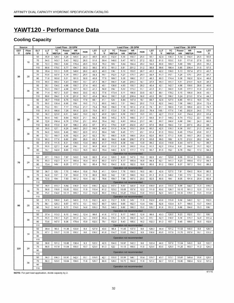
32
YAWT120 - Performance Data
NOTE: For part load application, divide capacity by 2.
AFFINITY DUAL CAPACITY HYDRONIC SPECIFICATION CATALOG
Cooling CapacitySource Load Flow - 18 GPM Load Flow - 28 GPM Load Flow - 36 GPM
EST°F
FlowGPM
ELT°F
LLT°F
TCMBTUH
PowerkW
HRMBTUH EER LST
°FLLT°F
TCMBTUH
PowerkW
HRMBTUH EER LST
°FLLT°F
TCMBTUH
PowerkW
HRMBTUH EER LST
°F
30
18
50 35.8 128.0 5.26 145.9 24.3 49.5 40.5 132.6 5.30 150.7 25.0 50.1 42.4 136.3 5.34 154.5 25.5 50.670 54.0 143.7 5.43 162.2 26.5 51.6 59.4 148.9 5.47 167.5 27.2 52.3 61.5 153.0 5.51 171.8 27.8 52.990 72.3 159.3 5.60 178.4 28.5 53.8 78.2 165.1 5.64 184.4 29.2 54.6 80.6 169.7 5.68 189.1 29.9 55.2110 90.6 175.0 5.77 194.7 30.3 56.0 97.0 181.3 5.81 201.2 31.2 56.8 99.6 186.4 5.85 206.4 31.9 57.5
28
50 35.4 131.3 5.05 148.6 26.0 42.9 40.3 136.1 5.10 153.5 26.7 43.3 42.2 139.9 5.13 157.4 27.3 43.770 53.6 147.6 5.18 165.2 28.5 44.4 59.1 152.9 5.22 170.7 29.3 44.8 61.3 157.1 5.26 175.1 29.9 45.290 71.8 163.8 5.31 181.9 30.9 45.8 77.9 169.7 5.35 188.0 31.7 46.3 80.3 174.4 5.38 192.8 32.4 46.8110 90.0 180.0 5.43 198.5 33.1 47.3 96.7 186.5 5.48 205.2 34.1 47.8 99.3 191.7 5.51 210.5 34.8 48.3
36
50 35.1 134.0 4.89 150.7 27.4 40.0 40.1 138.8 4.93 155.7 28.2 40.4 42.1 142.7 4.96 159.6 28.8 40.670 53.3 150.7 4.98 167.7 30.3 41.2 58.8 156.1 5.02 173.2 31.1 41.5 61.1 160.5 5.05 177.7 31.8 41.890 71.4 167.3 5.07 184.6 33.0 42.3 77.6 173.4 5.11 190.8 33.9 42.7 80.1 178.2 5.15 195.8 34.6 43.1110 89.6 184.0 5.16 201.6 35.7 43.4 96.4 190.7 5.20 208.4 36.6 43.9 99.1 196.0 5.24 213.9 37.4 44.3
50
18
50 36.7 119.8 6.79 142.9 17.6 69.1 41.1 124.1 6.84 147.4 18.1 69.7 42.9 127.5 6.89 151.0 18.5 70.170 55.0 135.4 6.95 159.1 19.5 71.2 60.0 140.3 7.01 164.2 20.0 71.9 62.0 144.2 7.06 168.3 20.4 72.490 73.2 151.1 7.12 175.4 21.2 73.4 78.8 156.5 7.18 181.0 21.8 74.1 81.1 160.9 7.23 185.6 22.3 74.7110 91.5 166.8 7.29 191.6 22.9 75.6 97.7 172.8 7.35 197.9 23.5 76.4 100.1 177.6 7.40 202.8 24.0 77.0
28
50 36.2 123.8 6.51 146.0 19.0 62.7 40.8 128.3 6.56 150.7 19.5 63.1 42.7 131.8 6.61 154.4 20.0 63.470 54.4 140.1 6.64 162.8 21.1 64.2 59.6 145.2 6.70 168.0 21.7 64.6 61.7 149.2 6.74 172.2 22.1 65.090 72.6 156.4 6.78 179.6 23.1 65.6 78.4 162.1 6.83 185.4 23.7 66.1 80.7 166.6 6.88 190.1 24.2 66.5110 90.8 172.8 6.91 196.3 25.0 67.1 97.2 179.0 6.97 202.8 25.7 67.6 99.8 184.0 7.01 207.9 26.2 68.1
36
50 35.9 127.1 6.29 148.5 20.2 59.9 40.6 131.6 6.34 153.3 20.8 60.2 42.5 135.3 6.38 157.1 21.2 60.570 54.0 143.9 6.40 165.7 22.5 61.0 59.4 149.1 6.45 171.1 23.1 61.4 61.5 153.2 6.49 175.4 23.6 61.790 72.1 160.7 6.50 182.9 24.7 62.2 78.1 166.5 6.55 188.9 25.4 62.6 80.5 171.2 6.60 193.7 26.0 62.9110 90.3 177.6 6.60 200.1 26.9 63.3 96.9 184.0 6.66 206.7 27.6 63.8 99.5 189.1 6.70 212.0 28.2 64.1
70
18
50 37.6 111.5 8.31 139.9 13.4 88.6 41.7 115.5 8.38 144.1 13.8 89.2 43.4 118.8 8.44 147.5 14.1 89.770 55.9 127.2 8.48 156.1 15.0 90.8 60.6 131.8 8.55 160.9 15.4 91.5 62.5 135.4 8.61 164.8 15.7 92.090 74.1 142.8 8.65 172.3 16.5 93.0 79.4 148.0 8.72 177.7 17.0 93.7 81.5 152.1 8.78 182.1 17.3 94.3110 Operation not recommended
28
50 37.1 116.3 7.97 143.5 14.6 82.5 41.4 120.5 8.03 147.9 15.0 82.9 43.1 123.8 8.09 151.4 15.3 83.270 55.3 132.7 8.11 160.4 16.4 83.9 60.2 137.5 8.17 165.4 16.8 84.4 62.1 141.3 8.23 169.4 17.2 84.790 73.4 149.1 8.25 177.2 18.1 85.4 79.0 154.5 8.32 182.9 18.6 85.9 81.2 158.8 8.37 187.3 19.0 86.3110 Operation not recommended
36
50 36.7 120.1 7.70 146.4 15.6 79.8 41.1 124.4 7.76 150.9 16.0 80.1 42.9 127.9 7.81 154.5 16.4 80.370 54.8 137.1 7.81 163.8 17.6 80.9 59.9 142.1 7.87 168.9 18.0 81.3 61.9 146.0 7.93 173.1 18.4 81.590 72.9 154.1 7.93 181.2 19.4 82.1 78.6 159.7 7.99 187.0 20.0 82.5 80.9 164.1 8.05 191.6 20.4 82.8110 Operation not recommended
90
18
50 38.5 103.3 9.84 136.8 10.5 108.2 42.4 107.0 9.92 140.8 10.8 108.8 43.9 110.0 9.98 144.0 11.0 109.270 56.8 118.9 10.00 153.0 11.9 110.4 61.2 123.2 10.09 157.6 12.2 111.0 63.0 126.7 10.15 161.3 12.5 111.590 75.0 134.6 10.17 169.3 13.2 112.6 80.0 139.4 10.25 174.4 13.6 113.3 82.0 143.3 10.32 178.5 13.9 113.8110 Operation not recommended
28
50 37.9 108.8 9.43 140.9 11.5 102.3 42.0 112.7 9.50 145.1 11.9 102.6 43.6 115.8 9.56 148.5 12.1 102.970 56.1 125.3 9.57 157.9 13.1 103.7 60.7 129.8 9.65 162.7 13.4 104.1 62.6 133.4 9.71 166.5 13.7 104.590 74.2 141.8 9.72 174.9 14.6 105.2 79.5 146.9 9.80 180.3 15.0 105.7 81.6 151.0 9.86 184.6 15.3 106.1110 Operation not recommended
36
50 37.4 113.2 9.10 144.2 12.4 99.6 41.6 117.2 9.17 148.5 12.8 99.9 43.3 120.5 9.23 152.0 13.1 100.170 55.5 130.3 9.23 161.8 14.1 100.8 60.4 135.0 9.30 166.8 14.5 101.1 62.3 138.8 9.36 170.7 14.8 101.490 73.6 147.5 9.36 179.4 15.8 102.0 79.1 152.8 9.43 185.0 16.2 102.3 81.3 157.1 9.49 189.5 16.5 102.6110 Operation not recommended
110
18
50 39.4 95.0 11.36 133.8 8.4 127.8 43.0 98.4 11.45 137.5 8.6 128.3 44.4 101.2 11.53 140.5 8.8 128.770 57.7 110.7 11.53 150.0 9.6 130.0 61.8 114.7 11.62 154.3 9.9 130.6 63.5 117.9 11.70 157.8 10.1 131.090
Operation not recommended110
28
50 38.8 101.2 10.88 138.4 9.3 122.0 42.5 104.9 10.97 142.3 9.6 122.4 44.0 107.8 11.04 145.5 9.8 122.770 56.9 117.8 11.04 155.5 10.7 123.5 61.3 122.1 11.13 160.0 11.0 123.9 63.0 125.5 11.20 163.7 11.2 124.290
Operation not recommended110
36
50 38.2 106.2 10.50 142.0 10.1 119.5 42.1 110.0 10.58 146.1 10.4 119.7 43.7 113.1 10.65 149.4 10.6 120.070 56.3 123.5 10.64 159.9 11.6 120.7 60.9 128.0 10.73 164.6 11.9 121.0 62.7 131.6 10.80 168.4 12.2 121.290
Operation not recommended110
4/1/10
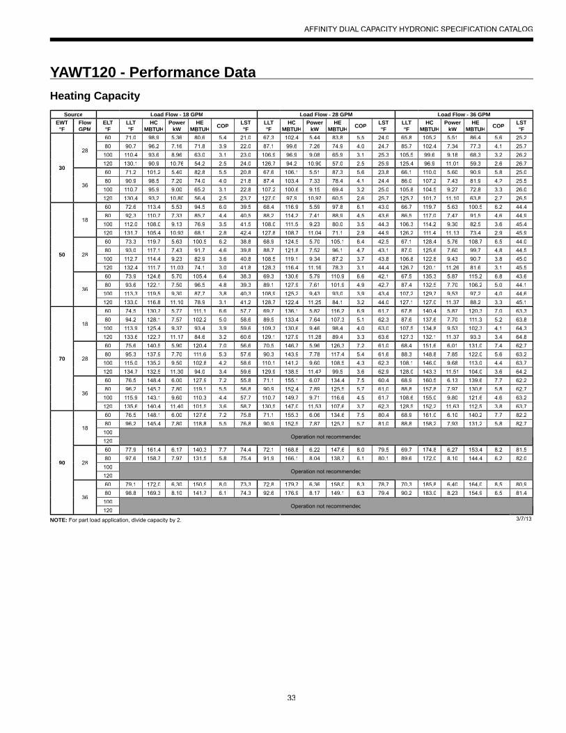
33
YAWT120 - Performance Data
NOTE: For part load application, divide capacity by 2.
AFFINITY DUAL CAPACITY HYDRONIC SPECIFICATION CATALOG
Heating CapacitySource Load Flow - 18 GPM Load Flow - 28 GPM Load Flow - 36 GPM
EWT°F
FlowGPM
ELT°F
LLT°F
HCMBTUH
PowerkW
HEMBTUH COP LST
°FLLT°F
HCMBTUH
PowerkW
HEMBTUH COP LST
°FLLT°F
HCMBTUH
PowerkW
HEMBTUH COP LST
°F
30
28
60 71.0 98.9 5.36 80.6 5.4 21.0 67.3 102.4 5.44 83.8 5.5 24.0 65.8 105.2 5.51 86.4 5.6 25.280 90.7 96.2 7.16 71.8 3.9 22.0 87.1 99.6 7.26 74.9 4.0 24.7 85.7 102.4 7.34 77.3 4.1 25.7100 110.4 93.6 8.96 63.0 3.1 23.0 106.9 96.9 9.08 65.9 3.1 25.3 105.5 99.6 9.18 68.3 3.2 26.2120 130.1 90.9 10.76 54.2 2.5 24.0 126.7 94.2 10.90 57.0 2.5 25.9 125.4 96.9 11.01 59.3 2.6 26.7
36
60 71.2 101.2 5.40 82.8 5.5 20.8 67.6 106.1 5.51 87.3 5.6 23.8 66.1 110.0 5.60 90.9 5.8 25.080 90.9 98.5 7.20 74.0 4.0 21.8 87.4 103.4 7.33 78.4 4.1 24.4 86.0 107.2 7.43 81.9 4.2 25.5100 110.7 95.9 9.00 65.2 3.1 22.8 107.2 100.6 9.15 69.4 3.2 25.0 105.8 104.5 9.27 72.8 3.3 26.0120 130.4 93.2 10.80 56.4 2.5 23.7 127.0 97.9 10.97 60.5 2.6 25.7 125.7 101.7 11.10 63.8 2.7 26.5
50
18
60 72.6 113.4 5.53 94.5 6.0 39.5 68.4 116.9 5.59 97.8 6.1 43.0 66.7 119.7 5.63 100.5 6.2 44.480 92.3 110.7 7.33 85.7 4.4 40.5 88.2 114.2 7.41 88.9 4.5 43.6 86.5 117.0 7.47 91.5 4.6 44.9100 112.0 108.0 9.13 76.9 3.5 41.5 108.0 111.5 9.23 80.0 3.5 44.3 106.3 114.2 9.30 82.5 3.6 45.4120 131.7 105.4 10.93 68.1 2.8 42.4 127.8 108.7 11.04 71.1 2.9 44.9 126.2 111.4 11.13 73.4 2.9 45.9
28
60 73.3 119.7 5.63 100.5 6.2 38.8 68.9 124.5 5.70 105.1 6.4 42.5 67.1 128.4 5.76 108.7 6.5 44.080 93.0 117.1 7.43 91.7 4.6 39.8 88.7 121.8 7.52 96.1 4.7 43.1 87.0 125.6 7.60 99.7 4.8 44.5100 112.7 114.4 9.23 82.9 3.6 40.8 108.5 119.1 9.34 87.2 3.7 43.8 106.8 122.8 9.43 90.7 3.8 45.0120 132.4 111.7 11.03 74.1 3.0 41.8 128.3 116.4 11.16 78.3 3.1 44.4 126.7 120.1 11.26 81.6 3.1 45.5
36
60 73.9 124.8 5.70 105.4 6.4 38.3 69.3 130.6 5.79 110.9 6.6 42.1 67.5 135.3 5.87 115.2 6.8 43.680 93.6 122.1 7.50 96.5 4.8 39.3 89.1 127.9 7.61 101.9 4.9 42.7 87.4 132.5 7.70 106.2 5.0 44.1100 113.3 119.5 9.30 87.7 3.8 40.3 108.9 125.2 9.43 93.0 3.9 43.4 107.2 129.7 9.53 97.2 4.0 44.6120 133.0 116.8 11.10 78.9 3.1 41.2 128.7 122.4 11.25 84.1 3.2 44.0 127.1 127.0 11.37 88.2 3.3 45.1
70
18
60 74.5 130.7 5.77 111.1 6.6 57.7 69.7 136.1 5.82 116.2 6.9 61.7 67.8 140.4 5.87 120.3 7.0 63.380 94.2 128.1 7.57 102.2 5.0 58.6 89.5 133.4 7.64 107.3 5.1 62.3 87.6 137.6 7.70 111.3 5.2 63.8100 113.9 125.4 9.37 93.4 3.9 59.6 109.3 130.6 9.46 98.4 4.0 63.0 107.5 134.8 9.53 102.3 4.1 64.3120 133.6 122.7 11.17 84.6 3.2 60.6 129.1 127.9 11.28 89.4 3.3 63.6 127.3 132.1 11.37 93.3 3.4 64.8
28
60 75.6 140.5 5.90 120.4 7.0 56.6 70.5 146.7 5.96 126.3 7.2 61.0 68.4 151.6 6.01 131.0 7.4 62.780 95.3 137.9 7.70 111.6 5.3 57.6 90.3 143.9 7.78 117.4 5.4 61.6 88.3 148.8 7.85 122.0 5.6 63.2100 115.0 135.2 9.50 102.8 4.2 58.6 110.1 141.2 9.60 108.5 4.3 62.3 108.1 146.0 9.68 113.0 4.4 63.7120 134.7 132.5 11.30 94.0 3.4 59.6 129.9 138.5 11.42 99.5 3.6 62.9 128.0 143.3 11.51 104.0 3.6 64.2
36
60 76.5 148.4 6.00 127.9 7.2 55.8 71.1 155.1 6.07 134.4 7.5 60.4 68.9 160.5 6.13 139.6 7.7 62.280 96.2 145.7 7.80 119.1 5.5 56.8 90.9 152.4 7.89 125.5 5.7 61.0 88.8 157.8 7.97 130.6 5.8 62.7100 115.9 143.1 9.60 110.3 4.4 57.7 110.7 149.7 9.71 116.6 4.5 61.7 108.6 155.0 9.80 121.6 4.6 63.2120 135.6 140.4 11.40 101.5 3.6 58.7 130.5 147.0 11.53 107.6 3.7 62.3 128.5 152.2 11.63 112.5 3.8 63.7
90
18
60 76.5 148.1 6.00 127.6 7.2 75.8 71.1 155.3 6.06 134.6 7.5 80.4 68.9 161.0 6.10 140.2 7.7 82.280 96.2 145.4 7.80 118.8 5.5 76.8 90.9 152.5 7.87 125.7 5.7 81.0 88.8 158.2 7.93 131.2 5.8 82.7100
Operation not recommended120
28
60 77.9 161.4 6.17 140.3 7.7 74.4 72.1 168.8 6.22 147.6 8.0 79.5 69.7 174.8 6.27 153.4 8.2 81.580 97.6 158.7 7.97 131.5 5.8 75.4 91.9 166.1 8.04 138.7 6.1 80.1 89.6 172.0 8.10 144.4 6.2 82.0100
Operation not recommended120
36
60 79.1 172.0 6.30 150.5 8.0 73.3 72.8 179.7 6.36 158.0 8.3 78.7 70.3 185.8 6.40 164.0 8.5 80.980 98.8 169.3 8.10 141.7 6.1 74.3 92.6 176.9 8.17 149.1 6.3 79.4 90.2 183.0 8.23 154.9 6.5 81.4100
Operation not recommended120
3/7/13

34
YAWT150 - Performance Data
NOTE: For part load application, divide capacity by 2.
AFFINITY DUAL CAPACITY HYDRONIC SPECIFICATION CATALOG
Cooling CapacitySource Load Flow - 21 GPM Load Flow - 32 GPM Load Flow - 42 GPM
EST°F
FlowGPM
ELT°F
LLT°F
TCMBTUH
PowerkW
HRMBTUH EER LST
°FLLT°F
TCMBTUH
PowerkW
HRMBTUH EER LST
°FLLT°F
TCMBTUH
PowerkW
HRMBTUH EER LST
°F
30
21
50 35.3 153.9 5.76 173.5 26.7 46.5 40.0 159.9 5.9 179.9 27.3 47.1 42.1 165.4 5.94 185.7 27.9 47.770 52.3 185.8 6.22 207.0 29.8 49.7 57.9 193.1 6.3 214.7 30.5 50.4 60.5 199.8 6.42 221.7 31.1 51.190 69.3 217.7 6.69 240.5 32.6 52.9 75.9 226.3 6.8 249.5 33.3 53.8 78.9 234.1 6.89 257.6 34.0 54.5110 86.2 249.6 7.15 274.0 34.9 56.1 93.8 259.5 7.3 284.2 35.7 57.1 97.2 268.4 7.37 293.5 36.4 58.0
32
50 34.3 164.4 5.5 183.1 30.0 41.4 39.3 171.1 5.6 190.1 30.7 41.9 41.6 177.3 5.7 196.6 31.3 42.370 51.1 198.7 5.93 218.9 33.5 43.7 57.1 206.7 6.0 227.3 34.3 44.2 59.8 214.0 6.11 234.9 35.0 44.790 67.8 233.1 6.37 254.8 36.6 45.9 74.9 242.4 6.5 264.4 37.5 46.5 78.1 250.8 6.57 273.2 38.2 47.1110 84.5 267.4 6.8 290.7 39.3 48.2 92.6 278.0 6.9 301.6 40.2 48.8 96.3 287.6 7.0 311.5 41.0 49.5
42
50 33.4 173.9 5.24 191.8 33.2 39.1 38.7 181.3 5.3 199.4 34.1 39.5 41.0 188.0 5.40 206.4 34.8 39.870 50.0 210.5 5.66 229.8 37.2 40.9 56.3 219.1 5.8 238.8 38.1 41.4 59.2 227.0 5.83 246.9 38.9 41.890 66.5 247.1 6.08 267.8 40.6 42.8 73.9 257.0 6.2 278.1 41.6 43.2 77.3 266.0 6.27 287.4 42.4 43.7110 83.0 283.7 6.50 305.8 43.6 44.6 91.6 294.8 6.6 317.4 44.6 45.1 95.5 305.0 6.70 327.9 45.5 45.6
50
21
50 36.4 143.2 7.49 168.8 19.1 66.1 40.7 148.9 7.6 174.9 19.6 66.7 42.7 154.0 7.73 180.4 19.9 67.270 53.3 175.2 8.02 202.5 21.9 69.3 58.6 182.1 8.1 209.9 22.4 70.0 61.0 188.4 8.26 216.6 22.8 70.690 70.3 207.2 8.54 236.3 24.3 72.5 76.5 215.3 8.7 244.9 24.8 73.3 79.4 222.7 8.80 252.8 25.3 74.1110 87.2 239.1 9.06 270.0 26.4 75.7 94.5 248.5 9.2 280.0 27.0 76.7 97.8 257.1 9.34 289.0 27.5 77.5
32
50 35.5 151.8 7.2 176.2 21.2 61.0 40.1 158.0 7.3 182.8 21.7 61.4 42.2 163.7 7.4 188.8 22.2 61.870 52.3 185.8 7.65 211.9 24.3 63.2 57.9 193.3 7.8 219.8 24.9 63.7 60.5 200.1 7.89 227.0 25.4 64.290 69.1 219.9 8.15 247.7 27.0 65.5 75.7 228.6 8.3 256.9 27.6 66.1 78.7 236.6 8.40 265.2 28.2 66.6110 85.8 253.9 8.6 283.4 29.4 67.7 93.5 263.9 8.8 293.9 30.0 68.4 97.0 273.0 8.9 303.4 30.6 69.0
42
50 34.8 159.6 6.84 182.9 23.3 58.7 39.6 166.3 6.9 190.1 23.9 59.1 41.8 172.5 7.05 196.6 24.5 59.470 51.4 195.5 7.32 220.5 26.7 60.5 57.3 203.5 7.4 228.9 27.4 60.9 60.0 210.8 7.54 236.6 28.0 61.390 68.0 231.4 7.79 258.0 29.7 62.3 75.0 240.7 7.9 267.7 30.4 62.7 78.1 249.2 8.03 276.6 31.0 63.2110 84.5 267.4 8.27 295.6 32.3 64.1 92.6 277.9 8.4 306.6 33.1 64.6 96.3 287.5 8.53 316.6 33.7 65.1
70
21
50 37.4 132.6 9.22 164.1 14.4 85.6 41.4 137.8 9.4 169.8 14.7 86.2 43.2 142.6 9.51 175.0 15.0 86.770 54.3 164.6 9.81 198.1 16.8 88.9 59.3 171.1 10.0 205.1 17.2 89.5 61.6 177.0 10.11 211.5 17.5 90.190 71.3 196.6 10.39 232.1 18.9 92.1 77.2 204.4 10.6 240.4 19.4 92.9 79.9 211.4 10.71 248.0 19.7 93.6110 Operation not recommended
32
50 36.7 139.2 8.8 169.3 15.8 80.6 40.9 144.9 9.0 175.5 16.2 81.0 42.9 150.1 9.1 181.1 16.5 81.370 53.5 172.9 9.37 204.9 18.5 82.8 58.8 179.9 9.52 212.4 18.9 83.3 61.1 186.2 9.66 219.2 19.3 83.790 70.3 206.7 9.93 240.5 20.8 85.0 76.6 214.9 10.09 249.3 21.3 85.6 79.4 222.4 10.23 257.3 21.7 86.1110 Operation not recommended
42
50 36.2 145.2 8.44 174.0 17.2 78.3 40.5 151.4 8.6 180.7 17.7 78.6 42.5 157.0 8.70 186.7 18.0 78.970 52.8 180.5 8.97 211.1 20.1 80.1 58.3 187.9 9.1 219.0 20.6 80.4 60.7 194.7 9.25 226.2 21.0 80.890 69.4 215.8 9.51 248.2 22.7 81.8 76.0 224.5 9.7 257.4 23.2 82.3 78.9 232.3 9.80 265.8 23.7 82.7110 Operation not recommended
90
21
50 38.4 122.0 10.96 159.3 11.1 105.2 42.1 126.8 11.1 164.8 11.4 105.7 43.8 131.1 11.30 169.7 11.6 106.270 55.3 154.0 11.60 193.6 13.3 108.4 60.0 160.1 11.79 200.3 13.6 109.1 62.1 165.6 11.96 206.4 13.8 109.790 72.3 186.1 12.24 227.8 15.2 111.7 77.9 193.4 12.44 235.9 15.5 112.5 80.5 200.1 12.62 243.1 15.8 113.2110 Operation not recommended
32
50 37.9 126.6 10.5 162.4 12.1 100.1 41.8 131.8 10.6 168.2 12.4 100.5 43.5 136.6 10.8 173.4 12.6 100.870 54.8 160.0 11.09 197.9 14.4 102.4 59.6 166.5 11.27 205.0 14.8 102.8 61.8 172.4 11.43 211.4 15.1 103.290 71.6 193.5 11.71 233.4 16.5 104.6 77.4 201.2 11.90 241.7 16.9 105.1 80.1 208.2 12.07 249.3 17.2 105.6110 Operation not recommended
42
50 37.5 130.9 10.04 165.1 13.0 97.9 41.5 136.4 10.2 171.3 13.4 98.2 43.3 141.5 10.35 176.8 13.7 98.470 54.2 165.5 10.63 201.8 15.6 99.6 59.2 172.3 10.80 209.2 16.0 100.0 61.5 178.5 10.96 215.9 16.3 100.390 70.9 200.2 11.22 238.5 17.8 101.4 77.0 208.2 11.40 247.1 18.3 101.8 79.7 215.5 11.57 255.0 18.6 102.1110 Operation not recommended
110
21
50 39.4 111.3 12.69 154.6 8.8 124.7 42.8 115.7 12.9 159.7 9.0 125.2 44.3 119.7 13.08 164.3 9.2 125.770 56.3 143.4 13.39 189.1 10.7 128.0 60.7 149.1 13.61 195.5 11.0 128.6 62.7 154.2 13.81 201.3 11.2 129.290
Operation not recommended110
32
50 39.1 114.1 12.1 155.5 9.4 119.7 42.6 118.7 12.3 160.8 9.6 120.1 44.1 123.0 12.5 165.7 9.8 120.470 56.0 147.2 12.81 190.9 11.5 121.9 60.4 153.1 13.02 197.5 11.8 122.3 62.5 158.5 13.21 203.5 12.0 122.790
Operation not recommended110
42
50 38.9 116.6 11.64 156.3 10.0 117.4 42.4 121.5 11.8 161.9 10.3 117.7 44.0 126.0 12.00 166.9 10.5 117.970 55.7 150.6 12.29 192.5 12.3 119.2 60.2 156.7 12.49 199.3 12.6 119.5 62.3 162.3 12.67 205.6 12.8 119.890
Operation not recommended110
2/15/10

35
YAWT150 - Performance Data
NOTE: For part load application, divide capacity by 2.
AFFINITY DUAL CAPACITY HYDRONIC SPECIFICATION CATALOG
Heating CapacitySource Load Flow - 21 GPM Load Flow - 32 GPM Load Flow - 42 GPM
EWT°F
FlowGPM
ELT°F
LLT°F
HCMBTUH
PowerkW
HEMBTUH COP LST
°FLLT°F
HCMBTUH
PowerkW
HEMBTUH COP LST
°FLLT°F
HCMBTUH
PowerkW
HEMBTUH COP LST
°F
30
32
60 72.6 132.7 7.7 106.4 5.0 19.9 68.4 133.8 7.6 107.9 5.2 23.3 66.4 134.7 7.4 109.3 5.3 24.880 92.0 126.1 11.0 88.6 3.4 21.6 88.0 127.6 10.8 90.8 3.5 24.3 86.1 128.9 10.6 92.7 3.6 25.6100 111.4 119.6 14.3 70.9 2.5 23.2 107.6 121.4 14.0 73.6 2.5 25.4 105.9 123.0 13.7 76.1 2.6 26.4120 130.8 113.0 17.6 53.1 1.9 24.9 127.2 115.2 17.2 56.5 2.0 26.5 125.6 117.1 16.9 59.6 2.0 27.2
42
60 72.9 135.9 7.8 109.4 5.1 19.6 68.6 137.0 7.6 111.0 5.3 23.1 66.6 138.0 7.5 112.4 5.4 24.680 92.3 129.2 11.1 91.5 3.4 21.3 88.2 130.7 10.9 93.6 3.5 24.1 86.3 132.0 10.7 95.6 3.6 25.4100 111.7 122.5 14.4 73.5 2.5 23.0 107.8 124.3 14.1 76.3 2.6 25.2 106.0 126.0 13.8 78.8 2.7 26.2120 131.0 115.8 17.7 55.5 1.9 24.7 127.4 118.0 17.3 58.9 2.0 26.3 125.7 120.0 17.0 62.0 2.1 27.0
50
21
60 75.6 163.4 8.3 135.3 5.8 37.1 70.3 164.7 8.1 137.1 6.0 41.4 67.9 165.9 8.0 138.7 6.1 43.480 94.9 156.0 11.2 117.8 4.1 38.8 89.9 157.8 11.0 120.3 4.2 42.5 87.6 159.4 10.8 122.6 4.3 44.2100 114.2 148.6 14.1 100.4 3.1 40.4 109.4 150.8 13.9 103.5 3.2 43.5 107.3 152.8 13.6 106.4 3.3 44.9120 133.4 141.2 17.1 82.9 2.4 42.1 129.0 143.9 16.7 86.8 2.5 44.6 127.0 146.3 16.4 90.3 2.6 45.7
32
60 76.0 168.0 8.3 139.6 5.9 36.7 70.6 169.3 8.2 141.4 6.1 41.2 68.1 170.5 8.0 143.1 6.2 43.280 95.3 160.3 11.3 121.8 4.2 38.4 90.1 162.1 11.1 124.4 4.3 42.2 87.8 163.8 10.9 126.7 4.4 44.0100 114.5 152.7 14.2 104.1 3.1 40.1 109.7 155.0 14.0 107.3 3.3 43.3 107.5 157.1 13.7 110.3 3.4 44.7120 133.8 145.1 17.2 86.4 2.5 41.8 129.2 147.8 16.9 90.3 2.6 44.4 127.2 150.3 16.5 93.9 2.7 45.5
42
60 76.4 172.0 8.4 143.4 6.0 36.3 70.8 173.4 8.2 145.3 6.2 40.9 68.3 174.7 8.1 147.0 6.3 43.080 95.6 164.2 11.4 125.5 4.2 38.1 90.4 166.1 11.2 128.0 4.4 42.0 88.0 167.8 11.0 130.4 4.5 43.8100 114.9 156.4 14.4 107.5 3.2 39.8 109.9 158.8 14.1 110.8 3.3 43.1 107.7 160.9 13.8 113.8 3.4 44.6120 134.2 148.6 17.3 89.5 2.5 41.5 129.5 151.4 17.0 93.5 2.6 44.2 127.3 154.0 16.7 97.1 2.7 45.4
70
21
60 78.8 197.8 8.9 167.5 6.5 54.0 72.5 199.3 8.7 169.6 6.7 59.4 69.6 200.8 8.6 171.5 6.9 61.880 98.0 189.3 11.5 150.1 4.8 55.7 92.0 191.4 11.3 153.0 5.0 60.4 89.2 193.4 11.1 155.6 5.1 62.6100 117.2 180.8 14.1 132.7 3.8 57.4 111.5 183.5 13.8 136.3 3.9 61.5 108.9 186.0 13.6 139.6 4.0 63.4120 136.4 172.3 16.7 115.3 3.0 59.0 131.0 175.6 16.4 119.7 3.1 62.5 128.5 178.6 16.1 123.7 3.3 64.1
32
60 79.4 203.2 8.9 172.7 6.7 53.6 72.8 204.8 8.8 174.9 6.8 59.1 69.8 206.3 8.6 176.8 7.0 61.680 98.5 194.5 11.6 155.0 4.9 55.2 92.3 196.7 11.4 157.9 5.1 60.1 89.5 198.7 11.2 160.6 5.2 62.4
100 117.7 185.8 14.2 137.3 3.8 56.9 111.8 188.6 13.9 141.0 4.0 61.2 109.1 191.1 13.7 144.4 4.1 63.1120 136.9 177.1 16.9 119.6 3.1 58.6 131.3 180.5 16.5 124.1 3.2 62.2 128.7 183.5 16.2 128.2 3.3 63.9
42
60 79.8 208.2 9.0 177.4 6.8 53.1 73.1 209.8 8.8 179.6 7.0 58.8 70.1 211.3 8.7 181.6 7.1 61.480 99.0 199.2 11.7 159.4 5.0 54.8 92.6 201.5 11.4 162.5 5.2 59.8 89.7 203.6 11.2 165.2 5.3 62.1100 118.1 190.3 14.3 141.5 3.9 56.5 112.1 193.2 14.0 145.3 4.0 60.9 109.3 195.8 13.8 148.7 4.2 62.9120 137.3 181.4 17.0 123.5 3.1 58.2 131.6 184.9 16.6 128.1 3.3 62.0 129.0 188.0 16.3 132.3 3.4 63.7
90
21
60 82.1 232.1 9.5 199.7 7.2 71.0 74.6 233.9 9.3 202.1 7.4 77.4 71.2 235.6 9.2 204.3 7.5 80.380 101.2 222.6 11.8 182.3 5.5 72.6 94.1 225.1 11.6 185.6 5.7 78.4 90.8 227.4 11.4 188.6 5.9 81.0100
Operation not recommended120
32
60 82.7 238.5 9.6 205.9 7.3 70.4 75.0 240.4 9.4 208.3 7.5 77.0 71.5 242.1 9.2 210.6 7.7 80.080 101.8 228.7 11.9 188.2 5.6 72.1 94.5 231.3 11.7 191.5 5.8 78.0 91.1 233.6 11.5 194.6 6.0 80.7100
Operation not recommended120
42
60 83.3 244.3 9.6 211.4 7.4 69.9 75.4 246.2 9.5 214.0 7.6 76.6 71.8 248.0 9.3 216.3 7.8 79.780 102.3 234.3 12.0 193.4 5.7 71.6 94.8 236.9 11.7 196.9 5.9 77.7 91.4 239.3 11.5 200.0 6.1 80.5100
Operation not recommended120
3/7/13
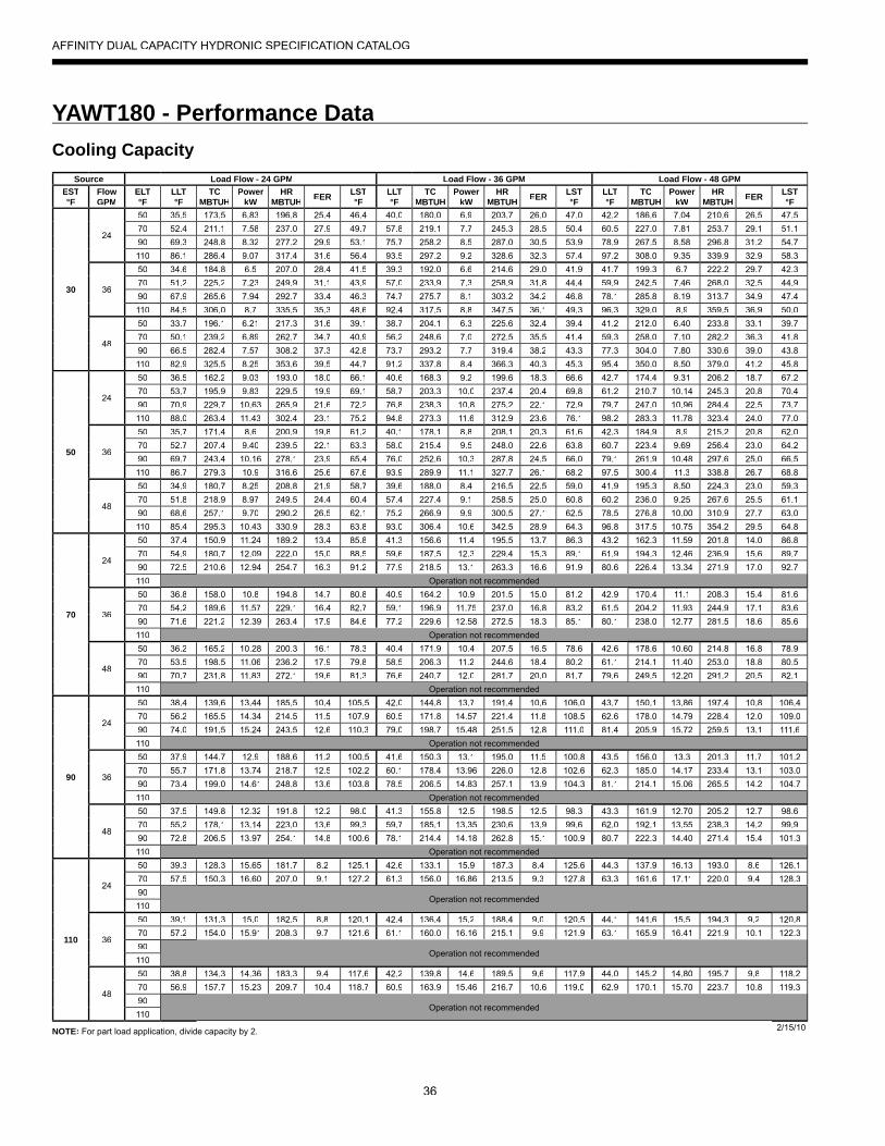
36
YAWT180 - Performance Data
NOTE: For part load application, divide capacity by 2.
AFFINITY DUAL CAPACITY HYDRONIC SPECIFICATION CATALOG
Cooling CapacitySource Load Flow - 24 GPM Load Flow - 36 GPM Load Flow - 48 GPM
EST°F
FlowGPM
ELT°F
LLT°F
TCMBTUH
PowerkW
HRMBTUH EER LST
°FLLT°F
TCMBTUH
PowerkW
HRMBTUH EER LST
°FLLT°F
TCMBTUH
PowerkW
HRMBTUH EER LST
°F
30
24
50 35.5 173.5 6.83 196.8 25.4 46.4 40.0 180.0 6.9 203.7 26.0 47.0 42.2 186.6 7.04 210.6 26.5 47.570 52.4 211.1 7.58 237.0 27.9 49.7 57.8 219.1 7.7 245.3 28.5 50.4 60.5 227.0 7.81 253.7 29.1 51.190 69.3 248.8 8.32 277.2 29.9 53.1 75.7 258.2 8.5 287.0 30.5 53.9 78.9 267.5 8.58 296.8 31.2 54.7110 86.1 286.4 9.07 317.4 31.6 56.4 93.5 297.2 9.2 328.6 32.3 57.4 97.2 308.0 9.35 339.9 32.9 58.3
36
50 34.6 184.8 6.5 207.0 28.4 41.5 39.3 192.0 6.6 214.6 29.0 41.9 41.7 199.3 6.7 222.2 29.7 42.370 51.2 225.2 7.23 249.9 31.1 43.9 57.0 233.9 7.3 258.9 31.8 44.4 59.9 242.5 7.46 268.0 32.5 44.990 67.9 265.6 7.94 292.7 33.4 46.3 74.7 275.7 8.1 303.2 34.2 46.8 78.1 285.8 8.19 313.7 34.9 47.4110 84.5 306.0 8.7 335.5 35.3 48.6 92.4 317.5 8.8 347.5 36.1 49.3 96.3 329.0 8.9 359.5 36.9 50.0
48
50 33.7 196.1 6.21 217.3 31.6 39.1 38.7 204.1 6.3 225.6 32.4 39.4 41.2 212.0 6.40 233.8 33.1 39.770 50.1 239.2 6.89 262.7 34.7 40.9 56.2 248.6 7.0 272.5 35.5 41.4 59.3 258.0 7.10 282.2 36.3 41.890 66.5 282.4 7.57 308.2 37.3 42.8 73.7 293.2 7.7 319.4 38.2 43.3 77.3 304.0 7.80 330.6 39.0 43.8110 82.9 325.5 8.25 353.6 39.5 44.7 91.2 337.8 8.4 366.3 40.3 45.3 95.4 350.0 8.50 379.0 41.2 45.8
50
24
50 36.5 162.2 9.03 193.0 18.0 66.1 40.6 168.3 9.2 199.6 18.3 66.6 42.7 174.4 9.31 206.2 18.7 67.270 53.7 195.9 9.83 229.5 19.9 69.1 58.7 203.3 10.0 237.4 20.4 69.8 61.2 210.7 10.14 245.3 20.8 70.490 70.9 229.7 10.63 265.9 21.6 72.2 76.8 238.3 10.8 275.2 22.1 72.9 79.7 247.0 10.96 284.4 22.5 73.7110 88.0 263.4 11.43 302.4 23.1 75.2 94.8 273.3 11.6 312.9 23.6 76.1 98.2 283.3 11.78 323.4 24.0 77.0
36
50 35.7 171.4 8.6 200.9 19.8 61.2 40.1 178.1 8.8 208.1 20.3 61.6 42.3 184.9 8.9 215.2 20.8 62.070 52.7 207.4 9.40 239.5 22.1 63.3 58.0 215.4 9.5 248.0 22.6 63.8 60.7 223.4 9.69 256.4 23.0 64.290 69.7 243.4 10.16 278.1 23.9 65.4 76.0 252.6 10.3 287.8 24.5 66.0 79.1 261.9 10.48 297.6 25.0 66.5110 86.7 279.3 10.9 316.6 25.6 67.6 93.9 289.9 11.1 327.7 26.1 68.2 97.5 300.4 11.3 338.8 26.7 68.8
48
50 34.9 180.7 8.25 208.8 21.9 58.7 39.6 188.0 8.4 216.5 22.5 59.0 41.9 195.3 8.50 224.3 23.0 59.370 51.8 218.9 8.97 249.5 24.4 60.4 57.4 227.4 9.1 258.5 25.0 60.8 60.2 236.0 9.25 267.6 25.5 61.190 68.6 257.1 9.70 290.2 26.5 62.1 75.2 266.9 9.9 300.5 27.1 62.5 78.5 276.8 10.00 310.9 27.7 63.0110 85.4 295.3 10.43 330.9 28.3 63.8 93.0 306.4 10.6 342.5 28.9 64.3 96.8 317.5 10.75 354.2 29.5 64.8
70
24
50 37.4 150.9 11.24 189.2 13.4 85.8 41.3 156.6 11.4 195.5 13.7 86.3 43.2 162.3 11.59 201.8 14.0 86.870 54.9 180.7 12.09 222.0 15.0 88.5 59.6 187.5 12.3 229.4 15.3 89.1 61.9 194.3 12.46 236.9 15.6 89.790 72.5 210.6 12.94 254.7 16.3 91.2 77.9 218.5 13.1 263.3 16.6 91.9 80.6 226.4 13.34 271.9 17.0 92.7110 Operation not recommended
36
50 36.8 158.0 10.8 194.8 14.7 80.8 40.9 164.2 10.9 201.5 15.0 81.2 42.9 170.4 11.1 208.3 15.4 81.670 54.2 189.6 11.57 229.1 16.4 82.7 59.1 196.9 11.75 237.0 16.8 83.2 61.5 204.2 11.93 244.9 17.1 83.690 71.6 221.2 12.39 263.4 17.9 84.6 77.2 229.6 12.58 272.5 18.3 85.1 80.1 238.0 12.77 281.5 18.6 85.6110 Operation not recommended
48
50 36.2 165.2 10.28 200.3 16.1 78.3 40.4 171.9 10.4 207.5 16.5 78.6 42.6 178.6 10.60 214.8 16.8 78.970 53.5 198.5 11.06 236.2 17.9 79.8 58.5 206.3 11.2 244.6 18.4 80.2 61.1 214.1 11.40 253.0 18.8 80.590 70.7 231.8 11.83 272.1 19.6 81.3 76.6 240.7 12.0 281.7 20.0 81.7 79.6 249.5 12.20 291.2 20.5 82.1110 Operation not recommended
90
24
50 38.4 139.6 13.44 185.5 10.4 105.5 42.0 144.8 13.7 191.4 10.6 106.0 43.7 150.1 13.86 197.4 10.8 106.470 56.2 165.5 14.34 214.5 11.5 107.9 60.5 171.8 14.57 221.4 11.8 108.5 62.6 178.0 14.79 228.4 12.0 109.090 74.0 191.5 15.24 243.5 12.6 110.3 79.0 198.7 15.48 251.5 12.8 111.0 81.4 205.9 15.72 259.5 13.1 111.6110 Operation not recommended
36
50 37.9 144.7 12.9 188.6 11.2 100.5 41.6 150.3 13.1 195.0 11.5 100.8 43.5 156.0 13.3 201.3 11.7 101.270 55.7 171.8 13.74 218.7 12.5 102.2 60.1 178.4 13.96 226.0 12.8 102.6 62.3 185.0 14.17 233.4 13.1 103.090 73.4 199.0 14.61 248.8 13.6 103.8 78.5 206.5 14.83 257.1 13.9 104.3 81.1 214.1 15.06 265.5 14.2 104.7110 Operation not recommended
48
50 37.5 149.8 12.32 191.8 12.2 98.0 41.3 155.8 12.5 198.5 12.5 98.3 43.3 161.9 12.70 205.2 12.7 98.670 55.2 178.1 13.14 223.0 13.6 99.3 59.7 185.1 13.35 230.6 13.9 99.6 62.0 192.1 13.55 238.3 14.2 99.990 72.8 206.5 13.97 254.1 14.8 100.6 78.1 214.4 14.18 262.8 15.1 100.9 80.7 222.3 14.40 271.4 15.4 101.3110 Operation not recommended
110
24
50 39.3 128.3 15.65 181.7 8.2 125.1 42.6 133.1 15.9 187.3 8.4 125.6 44.3 137.9 16.13 193.0 8.6 126.170 57.5 150.3 16.60 207.0 9.1 127.2 61.3 156.0 16.86 213.5 9.3 127.8 63.3 161.6 17.11 220.0 9.4 128.390
Operation not recommended110
36
50 39.1 131.3 15.0 182.5 8.8 120.1 42.4 136.4 15.2 188.4 9.0 120.5 44.1 141.6 15.5 194.3 9.2 120.870 57.2 154.0 15.91 208.3 9.7 121.6 61.1 160.0 16.16 215.1 9.9 121.9 63.1 165.9 16.41 221.9 10.1 122.390
Operation not recommended110
48
50 38.8 134.3 14.36 183.3 9.4 117.6 42.2 139.8 14.6 189.5 9.6 117.9 44.0 145.2 14.80 195.7 9.8 118.270 56.9 157.7 15.23 209.7 10.4 118.7 60.9 163.9 15.46 216.7 10.6 119.0 62.9 170.1 15.70 223.7 10.8 119.390
Operation not recommended110
2/15/10

37
YAWT180 - Performance Data
NOTE: For part load application, divide capacity by 2.
AFFINITY DUAL CAPACITY HYDRONIC SPECIFICATION CATALOG
Heating CapacitySource Load Flow - 24 GPM Load Flow - 36 GPM Load Flow - 48 GPM
EWT°F
FlowGPM
ELT°F
LLT°F
HCMBTUH
PowerkW
HEMBTUH COP LST
°FLLT°F
HCMBTUH
PowerkW
HEMBTUH COP LST
°FLLT°F
HCMBTUH
PowerkW
HEMBTUH COP LST
°F
30
36
60 72.7 152.0 9.7 119.1 4.6 20.1 68.5 153.2 9.5 120.8 4.7 23.3 66.4 154.3 9.3 122.5 4.8 24.980 92.0 143.7 12.6 100.6 3.3 21.6 88.1 145.2 12.4 102.9 3.4 24.3 86.1 146.8 12.2 105.2 3.5 25.6
100 111.3 135.4 15.6 82.1 2.5 23.2 107.6 137.3 15.3 85.0 2.6 25.3 105.8 139.2 15.0 87.9 2.7 26.3120 130.6 127.0 18.6 63.6 2.0 24.7 127.2 129.3 18.2 67.1 2.1 26.3 125.5 131.6 17.9 70.7 2.2 27.1
48
60 73.0 155.9 9.7 122.7 4.7 19.8 68.7 157.1 9.6 124.5 4.8 23.1 66.6 158.3 9.4 126.2 4.9 24.780 92.3 147.4 12.7 104.0 3.4 21.3 88.3 149.0 12.5 106.3 3.5 24.1 86.3 150.5 12.3 108.7 3.6 25.5
100 111.6 138.8 15.7 85.2 2.6 22.9 107.8 140.8 15.4 88.2 2.7 25.1 105.9 142.8 15.1 91.1 2.8 26.2120 130.9 130.3 18.7 66.4 2.0 24.5 127.4 132.6 18.4 70.0 2.1 26.1 125.6 135.0 18.0 73.6 2.2 26.9
50
24
60 75.6 187.3 10.1 152.8 5.4 37.3 70.5 188.8 10.0 154.8 5.6 41.4 67.9 190.2 9.8 156.8 5.7 43.580 94.8 177.3 13.1 132.6 4.0 39.0 90.0 179.3 12.9 135.3 4.1 42.5 87.5 181.2 12.7 138.0 4.2 44.3
100 113.9 167.4 16.1 112.3 3.0 40.6 109.4 169.7 15.8 115.8 3.1 43.6 107.2 172.1 15.5 119.2 3.3 45.0120 133.1 157.4 19.1 92.1 2.4 42.3 128.9 160.2 18.8 96.2 2.5 44.7 126.8 163.1 18.4 100.3 2.6 45.8
36
60 76.0 192.3 10.2 157.5 5.5 36.9 70.8 193.7 10.0 159.5 5.7 41.1 68.1 195.2 9.9 161.6 5.8 43.380 95.2 182.0 13.2 136.9 4.0 38.6 90.2 184.0 13.0 139.7 4.2 42.2 87.7 185.9 12.7 142.4 4.3 44.1
100 114.3 171.8 16.2 116.3 3.1 40.3 109.7 174.2 15.9 119.8 3.2 43.3 107.4 176.6 15.6 123.3 3.3 44.9120 133.5 161.5 19.3 95.8 2.5 42.0 129.1 164.4 18.9 100.0 2.6 44.4 127.0 167.4 18.5 104.2 2.6 45.7
48
60 76.4 197.2 10.3 162.1 5.6 36.5 71.0 198.7 10.1 164.2 5.8 40.9 68.3 200.2 9.9 166.3 5.9 43.180 95.6 186.7 13.3 141.2 4.1 38.2 90.5 188.7 13.1 144.0 4.2 42.0 87.9 190.7 12.8 146.9 4.4 43.9
100 114.7 176.2 16.4 120.3 3.2 40.0 109.9 178.7 16.1 123.9 3.3 43.1 107.5 181.2 15.8 127.4 3.4 44.7120 133.8 165.7 19.4 99.4 2.5 41.7 129.4 168.7 19.0 103.7 2.6 44.2 127.2 171.7 18.7 108.0 2.7 45.5
70
24
60 78.9 226.5 10.7 190.1 6.2 54.2 72.7 228.3 10.5 192.5 6.4 59.3 69.6 230.0 10.3 194.8 6.5 61.980 97.9 214.7 13.7 167.9 4.6 56.0 92.1 217.0 13.5 171.0 4.7 60.5 89.1 219.3 13.2 174.2 4.9 62.7
100 116.9 202.8 16.8 145.7 3.5 57.9 111.4 205.7 16.4 149.6 3.7 61.7 108.7 208.6 16.1 153.6 3.8 63.6120 135.9 191.0 19.8 123.4 2.8 59.7 130.8 194.5 19.4 128.2 2.9 62.9 128.2 197.9 19.0 132.9 3.0 64.5
36
60 79.4 232.5 10.8 195.8 6.3 53.7 73.0 234.3 10.6 198.2 6.5 59.0 69.8 236.0 10.4 200.6 6.7 61.680 98.4 220.3 13.8 173.2 4.7 55.6 92.4 222.7 13.6 176.4 4.8 60.2 89.4 225.1 13.3 179.6 5.0 62.5
100 117.3 208.2 16.9 150.6 3.6 57.5 111.7 211.1 16.6 154.6 3.7 61.4 108.9 214.1 16.3 158.6 3.9 63.4120 136.3 196.0 20.0 127.9 2.9 59.3 131.1 199.6 19.6 132.8 3.0 62.6 128.5 203.1 19.2 137.7 3.1 64.3
48
60 79.9 238.5 10.8 201.5 6.5 53.2 73.3 240.3 10.6 203.9 6.6 58.7 70.1 242.1 10.5 206.4 6.8 61.480 98.8 226.0 13.9 178.5 4.8 55.1 92.7 228.4 13.7 181.8 4.9 59.9 89.6 230.8 13.4 185.0 5.0 62.3
100 117.8 213.5 17.0 155.5 3.7 57.0 112.0 216.6 16.7 159.6 3.8 61.1 109.1 219.6 16.4 163.7 3.9 63.2120 136.8 201.0 20.1 132.4 2.9 59.0 131.4 204.7 19.7 137.4 3.0 62.4 128.7 208.3 19.3 142.4 3.2 64.1
90
24
60 82.1 265.8 11.2 227.5 6.9 71.0 74.9 267.8 11.0 230.2 7.1 77.2 71.2 269.8 10.8 232.8 7.3 80.380 101.0 252.0 14.3 203.2 5.2 73.1 94.2 254.7 14.0 206.8 5.3 78.5 90.7 257.5 13.8 210.4 5.5 81.2
100Operation not recommended
120
36
60 82.7 272.7 11.3 234.2 7.1 70.5 75.3 274.8 11.1 236.9 7.3 76.8 71.5 276.9 10.9 239.6 7.4 80.080 101.6 258.7 14.4 209.5 5.3 72.5 94.5 261.4 14.2 213.2 5.4 78.2 91.0 264.2 13.9 216.8 5.6 81.0
100Operation not recommended
120
48
60 83.3 279.7 11.4 240.9 7.2 69.9 75.7 281.9 11.2 243.7 7.4 76.5 71.8 284.0 11.0 246.5 7.6 79.780 102.1 265.3 14.5 215.7 5.4 72.0 94.9 268.2 14.3 219.5 5.5 77.8 91.3 271.0 14.0 223.2 5.7 80.7
100Operation not recommended
1203/7/13
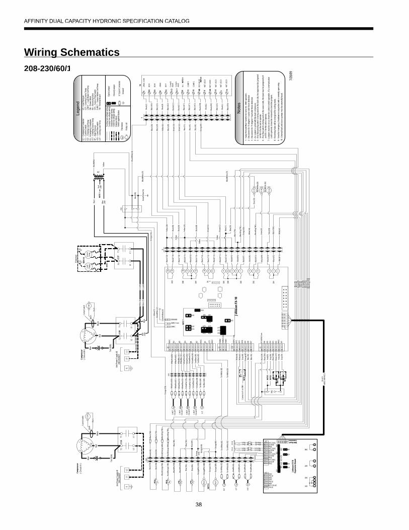
38
Wiring Schematicsg208-230/60/1
24V
Transformer
SFS
LFS
ES
John
son
FX-1
0
5VD
C
AI3
35 36 37 38
+- AI5
- + AI4
- + AI6
AI2
AI1
5VD
C
5VD
C
LED
- - -+ + +
24VAC
24VAC Com
GROUND
39 40 41
PWM
2
PWM
2 C
om
PWM
1
42 43 44 45 46 47 48
24VA
C C
om
DI1
2
DI1
1
DI1
0
DI9
DI8
DI7
49 50 51 52 53 54 55 56
DI 3
/4/5
/6/ C
om
DI6
DI5
DI4
DI3
DI2
DI1
9VD
C
20 19 18 17 16 15 14 13 12 11 10 9 8 7 6 5 4 3 2 1
D09
D08
D07 D0 6
D05
D04
D03
D02
D01
J8 J2 J10
J9
J7
NO
TE 7
A21A12
A25 A22
A32
A31A35
A23
A13
A11
A15
A14
A24
A34
A33
34
LP-A
LP-B
313029282726252423222120
AI4 EXP5Vdc Com
J2
5Vdc5Vdc Com
AI3 EXP5Vdc
5Vdc ComAI2 EXP
5Vdc5Vdc Com
AI1 EXP5Vdc
1716151413121110
DO324 Vac
DO4DO5
DO6
24 Vac24 Vac Com
J3
24 Vac
J1Main Board Connection
A41
A31
A23
A13
A43
A42
A32
A33
A21
A22
A12
A11
4
3
2
1
D02
D01
6
D07 5
8
D08 7
John
son
FX10
Expa
nsio
n B
oard
PB1 2 31
( Circ
uit B
)C
urre
nt S
witc
h
CSB
Blac
k
Blac
k
Com
pres
sor
Blac
k (F
1)
Blac
k (F2
)
Blac
k (F
3)
Blac
k (F4
)
Blac
k (F
5)
Blac
k (F6
)
Blac
k (F7
)
Blac
k (F
8)
Blac
k (F
9)
Blac
k (F
10)
Blac
k (F1
1)
Blac
k (F
12)
Blac
k (F1
3)
Blac
k (F1
4)
Blac
k (F
15)
Blac
k (F1
6)
Blac
k (F1
7)
Blac
k (F
18)
Blac
k (F
19)
Blac
k (F
20)
1234578910 611121316 15 141720 19 18A
33323130292827262524231 6 2 7 3 4 9 5 108
Whi
te/R
ed (8
0)
Whi
te/R
ed (8
1)
Whi
te/B
lue
(33)
Whi
te/B
lue
(34)
Yello
w/R
ed (3
5)
Yello
w/R
ed (3
6)
Yello
w/Bl
ue (3
7)
Yello
w/Bl
ue (3
8)
Tan/
Blac
k (84
)
Tan/
Blac
k (85
)
Whi
te/R
ed (8
0)
Whi
te/R
ed (8
1)T T TT
Whi
te/B
lue (
33)
Whi
te/B
lue (
34)
Yello
w/R
ed (3
5)
Yello
w/R
ed (3
6)
TYe
llow/
Blue
(37)
Yello
w/Bl
ue (3
8)
Tan/
Blac
k (84
)
Tan/
Blac
k (85
)
S-W
CT
Circ
uit A
L-W
CT
Circ
uit A
S-W
CT
Circ
uit B
L-W
CT
Circ
uit B
LLT
Blac
k
Red
208V
Blue
230V
Blac
k/Whi
te
Yello
w
Yello
w Yello
w
Yello
w
Yello
w (2
4)
Blac
k (95
)
Gre
en/Y
ello
w (2
3)
Yello
w (2
1)
Blac
k/Whi
te (2
2)
Y1C
OM
P 1
LC1
Com
p A
Alar
m
RS
DO-
9
X2
DO-
7
R24
VAC
SSD
O-8
LC2
Com
p B
Alar
m
X1Ac
c
C24
VAC
CO
M
TON
OT
USE
D
SCN
OT
USE
D
AIC
NO
T U
SED
LN
OT
USE
D
O/B
REV
VAL
VE
GN
OT
USE
D
Y2C
OM
P 2
1612829410 7531114 6 13151
TB
Blac
k (SS
)
Blac
k (C)
Blac
k (R
S)
Blac
k (R)
Blac
k (X
2)
Blac
k (LC
2)
Blac
k (LC
1)
Blac
k (X
1)
Blac
k (Y
1)
Blac
k (Y
2)
Blac
k (O
/B)
Blac
k (G
)
Blac
k (AI
C)
Blac
k (SC
)
Blac
k (L)
Blac
k (TO
)
B
7/28
/09
Blac
k/Whi
te (2
6)
Blac
k (30
)
Blac
k (30
)
Blac
k (29
)
Blac
k (29
)
Yello
w (2
5)
Yello
w (2
5)
Blac
k (28
)
Blac
k (28
)
Brow
n (53
)
Brow
n (53
)
Brow
n (52
)
Brow
n (52
)
Blue
(51)
Blue
(51)
Blac
k (75
A)
Blac
k/Org
(75B
)
CC-
B
CC-
A
Blac
k (64
A)
Viol
et (6
7)
Viol
et (6
6)
Blac
k/Whi
te (2
7)
Blac
k/Whi
te (2
7)
2 31PB
2
Blac
k (54
)
Red
(55)
Gra
y (56
)
Pink
(58)
Brow
n (57
)
Gra
y (59
)
6 15 7 16 9 8 17 14 518 13 4 1 31210 11 2T
EST
Brn/
Wht
(86)
Brn/
Wht
(87)
TLS
T
Brn/
Blk (
41)
Brn/
Blk (
42)
BlackBlack
CS-
AC
ircui
t A
BlackBlack
CS-
BC
ircui
t B
Blue
(45)
Blue
(45)
Blue
(46)
Blue
(46)
Blue
(45)
Blue
(46)
Ora
nge
(47)
Ora
nge
(47)
Ora
nge
(47)
Gra
y (48
)C
onne
ct to
R o
n PB
1-1
Whi
te (6
7)
Whi
te (6
7)
Whi
te (6
7)
Whi
te (6
6)
Whi
te (6
6)
Whi
te (6
6)
Blue
(50)
Ora
nge
(60)
Ora
nge
(60)
Ora
nge
(60)
Tan/
Whi
te (8
2)
Tan/
Whi
te (8
3)
Black (A)Black (A)
White (B)White (B)
Ora
nge
(61A
)
Ora
nge
(61A
)
Ora
nge
(61B
)
RV1
RV2
Ora
nge
(60A
)
Ora
nge
(61A
)
Ora
nge/W
ht (6
0B)
Ora
nge/W
ht (6
1B)
TEL
T
Tan/
Whi
te (8
2)
Tan/
Whi
te (8
3)
Tan/
Whi
te (8
2)
Tan/
Whi
te (8
3)
Blac
k (49
)
Blue
(76A
)
Blue
(76A
)
Blue
(76B
)
Blue
(76B
)
Blue
(49A
)
Blue
(76A
)
Blue
/Wht
(49B
)
Blue
/Wht
(76B
)
BLAC
KW
IRE
HAR
NES
S
Blac
k (70
A)
Blac
k/Org
(70B
)
NO
TE 2
NO
TE 3
Not
es
3 -D
isco
nnec
t for
15
degr
ee F
load
sid
e fre
eze
dete
ctio
n
4 -A
cc o
utpu
t is
cycl
ed w
ith th
e le
ad c
ompr
esso
r.5
-If n
o flo
w p
rovi
ng s
witc
h is
bei
ng u
sed
on th
e lo
ad s
ide,
the
inpu
t mus
t be
jum
pere
d
to
PB2-
3 fo
r the
uni
t to
oper
ate.
2 -D
isco
nnec
t for
15
degr
ee F
sou
rce
side
free
ze d
etec
tion
7 -J
umpe
rs m
ust b
e se
t as
show
n fo
r cor
rect
con
trol o
pera
tion.
If a
com
mun
icat
ion
c
ard
is p
rese
nt, i
t mus
t be
rem
oved
to c
heck
the
jum
pers
.
6 -I
f no
flow
sw
itch
is b
eing
use
d on
the
sour
ce s
ide,
the
inpu
t mus
t be
jum
pere
d to
R
o
n PB
1-1
for t
he u
nit t
o op
erat
e.
1 -S
wap
Red
and
Blu
e Tr
ansf
orm
er w
ires
for
208V
ope
ratio
n.
8 -R
ever
sing
Val
ve w
ill be
ene
rgiz
ed fo
r coo
ling
mod
e.
9 -U
sed
for E
mer
genc
y Sh
utdo
wn
in c
onju
nctio
n w
ith a
nor
mal
ly o
pen
rela
yNO
TE 4
NO
TE 5
NO
TE 6
NO
TE 8
NO
TE 8
NO
TE 9
NO
TE 1
Gro
und
Lege
ndC
C –
Com
pres
sor C
onta
ctor
CS
– C
urre
nt S
witc
hEL
T –
Ente
ring
Load
Tem
pES
– E
mer
genc
y Sh
utdo
wn
EST
– En
terin
g So
urce
Tem
pH
P –
Hig
h Pr
essu
reLF
S –
Load
Flo
w S
witc
hLL
T –
Leav
ing
Load
Tem
p
LP –
Low
Pre
ssur
eLS
T –
Leav
ing
Sour
ce T
emp
L-W
CT
– Lo
ad W
ater
Coi
l Tem
pPB
– P
ower
Blo
ckR
V –
Rev
ersi
ng V
alve
SFS
– So
urce
Flo
w S
witc
hS-
WC
T –
Sour
ce W
ater
Coi
l Tem
pTB
– T
erm
inal
Boa
rd
Fact
ory
low
vol
tage
wiri
ngFa
ctor
y lin
e vo
ltage
wiri
ngFi
eld
low
vol
tage
wiri
ngFi
eld
line
volta
ge w
iring
Opt
iona
l blo
ckFi
eld
Supp
lied
Opt
ion
Ther
mis
tor
Rel
ay c
oil
T
Ope
n Ju
mpe
r
Clo
sed
Jum
per
¼” Q
uick
Con
nect
or
HP-
A
HP-
BBl
ack/O
rang
e (7
4B)
Blac
k/Ora
nge
(73B
)
Blac
k (74
A)
Blac
k (73
A)
Blac
k (65
A)
Blac
k/Ora
nge
(64B
)
Blac
k/Ora
nge
(65B
)
Blac
k (70
A)
Blac
k/Org
(70B
)Bl
ack (
75A
)
Blac
k/Org
(75B
)
Blac
k (70
A)
Blac
k/Org
(70B
)
Blac
k (75
A)
Blac
k/Org
(75B
)
( Circ
uit A
)C
ompr
esso
r
Cur
rent
Sw
itch
CSA
Blac
k
Blac
k
Gre
en/Y
ello
w (1
6)
EX1
EX2
Ora
nge
(61A
)
C
R
S
C
R
S
Uni
t Pow
er S
uppl
y #2
208-
230/
60/1
GL1
L2
Uni
t Pow
er S
uppl
y #1
208-
230/
60/1
GL1
L2
CC
A
L1L2
T1T2
Blac
k
Tan
(52A
)
Blue
Red
CC
B
L1L2
T1T2
Red
Blac
k
CC
P
L1L2
T1T2
Blac
k/Whi
te (2
6)
Blac
k/Whi
te (6
2)
Blue
(50)
Tan
(52B
)
Blac
kBl
ue23
0V
Whi
te (8
)
Blac
k (7)
G
Load
Pu
mp
G
Ext
erna
l
Sour
cePu
mp
NO
TE 1
0
10 -
Exte
rnal
load
and
sou
rce
pum
ps m
ust b
e ex
tern
ally
fuse
d.
CC-
P
Blue
12 A
WB
12 A
WB
AFFINITY DUAL CAPACITY HYDRONIC SPECIFICATION CATALOG
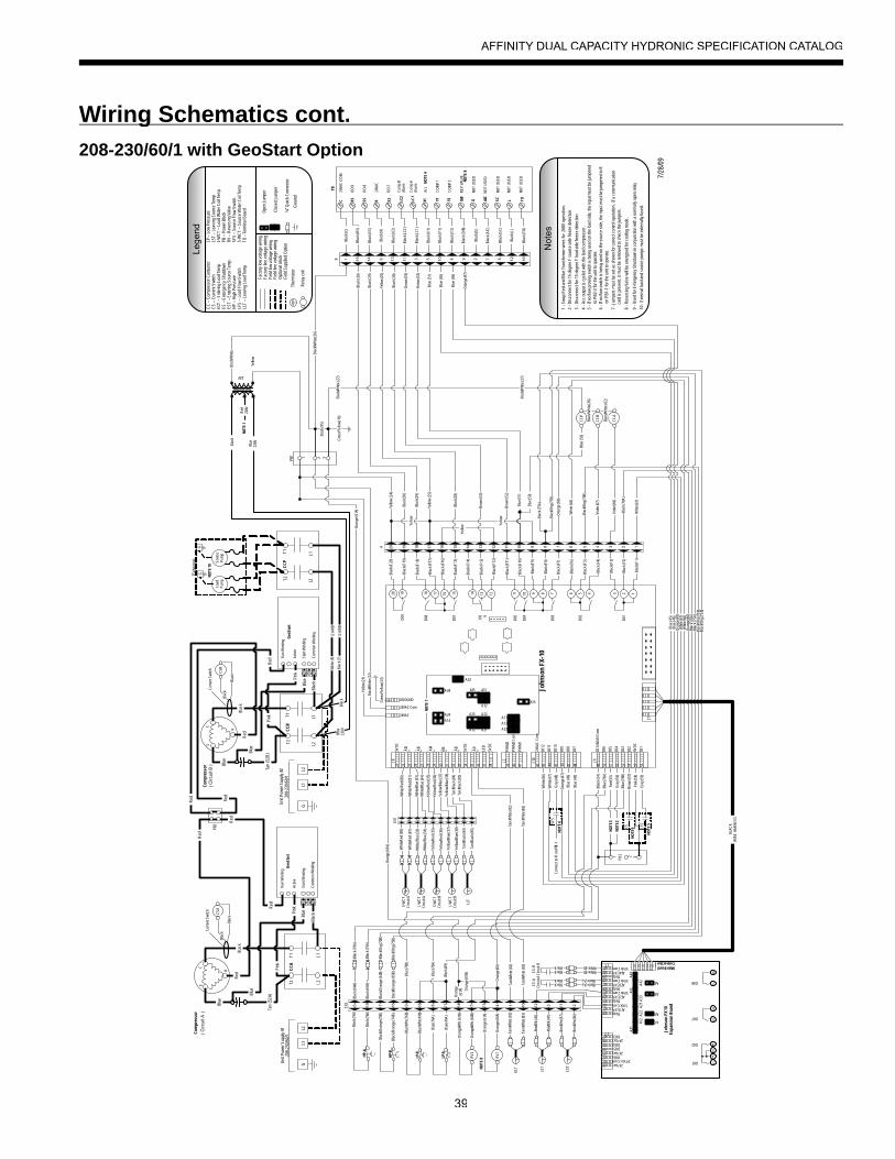
39
Wiring Schematics cont.g208-230/60/1 with GeoStart Option
24V
Transformer
SFS
LFS
ES
John
son
FX-1
0
5VD
C
AI3
35 36 37 38
+- AI5
- + AI4
- + AI6
AI2
AI1
5VD
C
5VD
C
LED
- - -+ + +
24VAC
24VAC Com
GROUND
39 40 41
PWM
2
PWM
2 C
om
PWM
1
42 43 44 45 46 47 48
24VA
C C
om
DI1
2
DI1
1
DI1
0
DI9
DI8
DI7
49 50 51 52 53 54 55 56
DI 3
/4/5
/6/ C
om
DI6
DI5
DI4
DI3
DI2
DI1
9VD
C
20 19 18 17 16 15 14 13 12 11 10 9 8 7 6 5 4 3 2 1
D09
D08
D07 D0 6
D05
D04
D03
D02
D01
J8 J2 J10
J9
J7
NO
TE 7
A21A12
A25 A22
A32
A31A35
A23
A13
A11
A15
A14
A24
A34
A33
34
LP-A
LP-B
313029282726252423222120
AI4 EXP5Vdc Com
J2
5Vdc5Vdc Com
AI3 EXP5Vdc
5Vdc ComAI2 EXP
5Vdc5Vdc Com
AI1 EXP5Vdc
1716151413121110
DO324 Vac
DO4DO5
DO6
24 Vac24 Vac Com
J3
24 Vac
J1Main Board Connection
A41
A31
A23
A13
A43
A42
A32
A33
A21
A22
A12
A11
4
3
2
1
D02
D01
6
D07 5
8
D08 7
John
son
FX10
Expa
nsio
n B
oard
PB1 2 31
( Circ
uit B
)C
urre
nt S
witc
h
CSB
Blac
k
Blac
k
Com
pres
sor
Blac
k (F
1)
Blac
k (F2
)
Blac
k (F
3)
Blac
k (F4
)
Blac
k (F
5)
Blac
k (F6
)
Blac
k (F7
)
Blac
k (F
8)
Blac
k (F
9)
Blac
k (F
10)
Blac
k (F1
1)
Blac
k (F
12)
Blac
k (F1
3)
Blac
k (F1
4)
Blac
k (F
15)
Blac
k (F1
6)
Blac
k (F1
7)
Blac
k (F
18)
Blac
k (F
19)
Blac
k (F
20)
1234578910 611121316 15 141720 19 18A
33323130292827262524231 6 2 7 3 4 9 5 108
Whi
te/R
ed (8
0)
Whi
te/R
ed (8
1)
Whi
te/B
lue
(33)
Whi
te/B
lue
(34)
Yello
w/R
ed (3
5)
Yello
w/R
ed (3
6)
Yello
w/Bl
ue (3
7)
Yello
w/Bl
ue (3
8)
Tan/
Blac
k (84
)
Tan/
Blac
k (85
)
Whi
te/R
ed (8
0)
Whi
te/R
ed (8
1)T T TT
Whi
te/B
lue (
33)
Whi
te/B
lue (
34)
Yello
w/R
ed (3
5)
Yello
w/R
ed (3
6)
TYe
llow/
Blue
(37)
Yello
w/Bl
ue (3
8)
Tan/
Blac
k (84
)
Tan/
Blac
k (85
)
S-W
CT
Circ
uit A
L-W
CT
Circ
uit A
S-W
CT
Circ
uit B
L-W
CT
Circ
uit B
LLT
Blac
k
Red
208V
Blue
230V
Blac
k/Whi
te
Yello
w
Yello
w Yello
w
Yello
w
Yello
w (2
4)
Blac
k (95
)
Gre
en/Y
ello
w (2
3)
Yello
w (2
1)
Blac
k/Whi
te (2
2)
Y1C
OM
P 1
LC1
Com
p A
Alar
m
RS
DO-
9
X2
DO-
7
R24
VAC
SSD
O-8
LC2
Com
p B
Alar
m
X1Ac
c
C24
VAC
CO
M
TON
OT
USE
D
SCN
OT
USE
D
AIC
NO
T U
SED
LN
OT
USE
D
O/B
REV
VAL
VE
GN
OT
USE
D
Y2C
OM
P 2
1612829410 7531114 6 13151
TB
Blac
k (SS
)
Blac
k (C)
Blac
k (R
S)
Blac
k (R)
Blac
k (X
2)
Blac
k (LC
2)
Blac
k (LC
1)
Blac
k (X
1)
Blac
k (Y
1)
Blac
k (Y
2)
Blac
k (O
/B)
Blac
k (G
)
Blac
k (AI
C)
Blac
k (SC
)
Blac
k (L)
Blac
k (TO
)
B
7/28
/09
Blac
k/Whi
te (2
6)
Blac
k (30
)
Blac
k (30
)
Blac
k (29
)
Blac
k (29
)
Yello
w (2
5)
Yello
w (2
5)
Blac
k (28
)
Blac
k (28
)
Brow
n (53
)
Brow
n (53
)
Brow
n (52
)
Brow
n (52
)
Blue
(51)
Blue
(51)
Blac
k (75
A)
Blac
k/Org
(75B
)
CC-
B
CC-
A
Blac
k (64
A)
Viol
et (6
7)
Viol
et (6
6)
Blac
k/Whi
te (2
7)
Blac
k/Whi
te (2
7)
2 31PB
2
Blac
k (54
)
Red
(55)
Gra
y (56
)
Pink
(58)
Brow
n (57
)
Gra
y (59
)
6 15 7 16 9 8 17 14 518 13 4 1 31210 11 2T
EST
Brn/
Wht
(86)
Brn/
Wht
(87)
TLS
T
Brn/
Blk (
41)
Brn/
Blk (
42)
BlackBlack
CS-
AC
ircui
t A
BlackBlack
CS-
BC
ircui
t B
Blue
(45)
Blue
(45)
Blue
(46)
Blue
(46)
Blue
(45)
Blue
(46)
Ora
nge
(47)
Ora
nge
(47)
Ora
nge
(47)
Gra
y (48
)C
onne
ct to
R o
n PB
1-1
Whi
te (6
7)
Whi
te (6
7)
Whi
te (6
7)
Whi
te (6
6)
Whi
te (6
6)
Whi
te (6
6)
Blue
(50)
Ora
nge
(60)
Ora
nge
(60)
Ora
nge
(60)
Tan/
Whi
te (8
2)
Tan/
Whi
te (8
3)
Black (A)Black (A)
White (B)White (B)
Ora
nge
(61A
)
Ora
nge
(61A
)
Ora
nge
(61B
)
RV1
RV2
Ora
nge
(60A
)
Ora
nge
(61A
)
Ora
nge/W
ht (6
0B)
Ora
nge/W
ht (6
1B)
TEL
T
Tan/
Whi
te (8
2)
Tan/
Whi
te (8
3)
Tan/
Whi
te (8
2)
Tan/
Whi
te (8
3)
Blac
k (49
)
Blue
(76A
)
Blue
(76A
)
Blue
(76B
)
Blue
(76B
)
Blue
(49A
)
Blue
(76A
)
Blue
/Wht
(49B
)
Blue
/Wht
(76B
)
BLAC
KW
IRE
HAR
NES
S
Blac
k (70
A)
Blac
k/Org
(70B
)
NO
TE 2
NO
TE 3
Not
es
3 -D
isco
nnec
t for
15
degr
ee F
load
sid
e fre
eze
dete
ctio
n
4 -A
cc o
utpu
t is
cycl
ed w
ith th
e le
ad c
ompr
esso
r.5
-If n
o flo
w p
rovi
ng s
witc
h is
bei
ng u
sed
on th
e lo
ad s
ide,
the
inpu
t mus
t be
jum
pere
d
to
PB2
-3 fo
r the
uni
t to
oper
ate.
2 -D
isco
nnec
t for
15
degr
ee F
sou
rce
side
free
ze d
etec
tion
7 -J
umpe
rs m
ust b
e se
t as
show
n fo
r cor
rect
con
trol o
pera
tion.
If a
com
mun
icat
ion
c
ard
is p
rese
nt, i
t mus
t be
rem
oved
to c
heck
the
jum
pers
.
6 -I
f no
flow
sw
itch
is b
eing
use
d on
the
sour
ce s
ide,
the
inpu
t mus
t be
jum
pere
d to
R
on
PB1
-1 fo
r the
uni
t to
oper
ate.
1 -S
wap
Red
and
Blu
e Tr
ansf
orm
er w
ires
for
208V
ope
ratio
n.
8 -R
ever
sing
Val
ve w
ill be
ene
rgiz
ed fo
r coo
ling
mod
e.
9 -U
sed
for E
mer
genc
y Sh
utdo
wn
in c
onju
nctio
n w
ith a
nor
mal
ly o
pen
rela
yNO
TE 4
NO
TE 5
NO
TE 6
NO
TE 8
NO
TE 8
NO
TE 9
NO
TE 1
Gro
und
Lege
ndC
C –
Com
pres
sor C
onta
ctor
CS
– C
urre
nt S
witc
hEL
T –
Ente
ring
Load
Tem
pES
– E
mer
genc
y Sh
utdo
wn
EST
– En
terin
g So
urce
Tem
pH
P –
Hig
h Pr
essu
reLF
S –
Load
Flo
w S
witc
hLL
T –
Leav
ing
Load
Tem
p
LP –
Low
Pre
ssur
eLS
T –
Leav
ing
Sour
ce T
emp
L-W
CT
– Lo
ad W
ater
Coi
l Tem
pPB
– P
ower
Blo
ckR
V –
Rev
ersi
ng V
alve
SFS
– So
urce
Flo
w S
witc
hS-
WC
T –
Sour
ce W
ater
Coi
l Tem
pTB
– T
erm
inal
Boa
rd
Fact
ory
low
vol
tage
wiri
ngFa
ctor
y lin
e vo
ltage
wiri
ngFi
eld
low
vol
tage
wiri
ngFi
eld
line
volta
ge w
iring
Opt
iona
l blo
ckFi
eld
Supp
lied
Opt
ion
Ther
mis
tor
Rel
ay c
oil
T
Ope
n Ju
mpe
r
Clo
sed
Jum
per
¼” Q
uick
Con
nect
or
HP-
A
HP-
BBl
ack/O
rang
e (7
4B)
Blac
k/Ora
nge
(73B
)
Blac
k (74
A)
Blac
k (73
A)
Blac
k (65
A)
Blac
k/Ora
nge
(64B
)
Blac
k/Ora
nge
(65B
)
Blac
k (70
A)
Blac
k/Org
(70B
)Bl
ack (
75A
)
Blac
k/Org
(75B
)
Blac
k (70
A)
Blac
k/Org
(70B
)
Blac
k (75
A)
Blac
k/Org
(75B
)
( Circ
uit A
)C
ompr
esso
r
Cur
rent
Sw
itch
CSA
Blac
k
Blac
k
Gre
en/Y
ello
w (1
6)
EX1
EX2
Ora
nge
(61A
)
C
R
S
C
R
S
Geo
Star
t
Run
Win
ding
Activ
e
Star
t Win
ding
Com
mon
Win
ding
Uni
t Pow
er S
uppl
y #2
208-
230/
60/1
GL1
L2
Uni
t Pow
er S
uppl
y #1
208-
230/
60/1
GL1
L2
CC
A
L1L2
T1T2
Blac
k
PB3
Tan
(52A
)
Blue
Blac
k
BluePi
nk
Blue
Pink
Red
Red
Red
Red
CC
B
L1L2
T1T2
Geo
Star
t
Run
Win
ding
Activ
e
Star
t Win
ding
Com
mon
Win
ding
Red Red
Red
Red
Blac
k
Pink
CC
P
L1L2
T1T2
Blac
k/Whi
te (2
6)
Blac
k/Whi
te (6
2)
Blue
(50)
Tan
(52B
)
Blac
kBl
ue23
0V
Whi
te (8
)
Blac
k (7)
G
Load
Pu
mp
GE
xter
nal
Sour
cePu
mp
NO
TE 1
0
10 -
Exte
rnal
load
and
sou
rce
pum
ps m
ust b
e ex
tern
ally
fuse
d.
CC-
P
Blue
Blac
k
Blue
Pink
Blue
12 A
WB
12 A
WB
AFFINITY DUAL CAPACITY HYDRONIC SPECIFICATION CATALOG
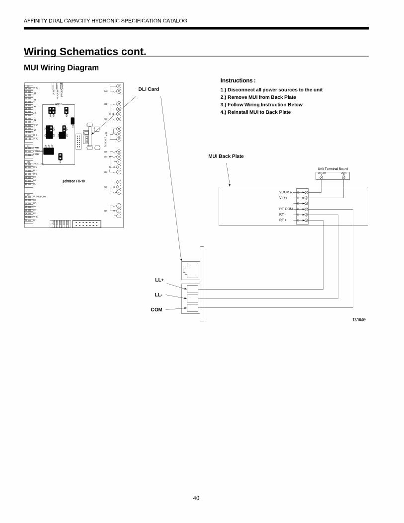
40
Wiring Schematics cont.gMUI Wiring Diagram
Johnson FX-10
5VDC
AI3
35
36
37
38
+
-
AI5-
+
AI4-
+
AI6
AI2
AI1
5VDC
5VDC
LED
-
-
-
+
+
+
24VA
C
24VA
C Com
GR
OU
ND
39
40
41
PWM2
PWM2 Com
PWM1
42
43
44
45
46
47
48
24VAC Com
DI12
DI11
DI10
DI9
DI8
DI7
49
50
51
52
53
54
55
56
DI 3/4/5/6/ Com
DI6
DI5
DI4
DI3
DI2
DI1
9VDC
20
19
18
17
16
15
14
13
12
11
10
9
8
7
6
5
4
3
2
1
D09
D08
D07
D06
D05
D04
D03
D02
D01
J8
J2
J10
J9
J7
NOTE 7
A21A12
A25
A22
A32
A31
A35
A23
A13
A11
A15
A14
A24
A34
A3334
33
32
31
30
29
28
27
26
25
24
23
12/10/09
DLI Card
LL+
LL-
COM
VCOM (-)V (+)
RT COMRT -RT +
Unit Terminal Board24VAC24V COM
RC
2.) Remove MUI from Back Plate3.) Follow Wiring Instruction Below4.) Reinstall MUI to Back Plate
MUI Back Plate
Instructions :1.) Disconnect all power sources to the unit
AFFINITY DUAL CAPACITY HYDRONIC SPECIFICATION CATALOG

41
Flow Proving SwitchThe FPS300 flow switch is designed to detect the presence or absence of flow in the piping of a water source heat pump. In water sourceheat pumps the flow switch is normally used to shut off the compressor whenever there is not circulation of the brine solution through thebraze plate or coaxial heat exchanger. A lack of circulation can damage braze plate or coaxial heat exchangers if freezing occurs.
Load and Source Piping ConnectionsThe Affinity has two connection options available. Each kit is intended to connect one piping connection. Therefore, two kits will be requiredfor each unit. The kits can be mixed for installer convenience, one onsource and the other on load.
CKNDW1 - Strainer Connection Kit includes a 2 in. copper teewith integral P/T plug and a 2 in. “Y” strainer. Other components to complete the all copper piping can be sourced locally.
HHK162S - Strainer Hose Kit set includes a 2 in. stainless steelSbraided hose with integral P/T plug and a 2 in. “Y” strainer.
Strainers
All units shall have a field-installed 2 in. Y-strainer with a self-aligning screen and 1 in.blow-off port to reduce debris that will enter the condenser/evaporator. Strainers should be made of a brass body with a 316 stainless steel 20-40 mesh screen.
WARNING: Warranty is void if strainers are not used on the entering side of the load and source.
Earth Loop and Load-side Pump Kits (Field Installed)A specially designed one or two-pump module provides all liquid flow, fill and connection requirements for independent single unitsystems (230/60/1 only).
Calculate the system pressure drop then refer to the pump curves to select the proper pump. All of the pump kits can be used for hydronic heating applications as long as they meet the flow requirements. If the flow requirements are outside the pumpcurve, an alternate pump will need to be obtained to maintain the necessary flow.
FCM2-3023 -3 UPS60-150 (x2), cast iron pump volute, 3-speed, 2 in.full-port
FCL1-5028 -8 UPS32-160, cast iron pump volute, 3-speed, 2 in.full-port
FCL1-5038 -8 UPS40-160, cast iron pump volute, 3-speed, 2 in.full-port
FCL1-5055 -5 UPS40-240, cast iron pump volute, 3-speed, 2 in.full-port
HydroZone Tank ControllerTank controller (HZC) that adds outdoor reset with warm weather shutdown, setpoint control, process control, and management of four compressor outputs for our water-to-water systems.
HZABThis is used in conjunction with the HydroZone to control the Geo-Storage tank electric heating element.
CKNDW1HHK162S
Accessories and Optionsp
AFFINITY DUAL CAPACITY HYDRONIC SPECIFICATION CATALOG
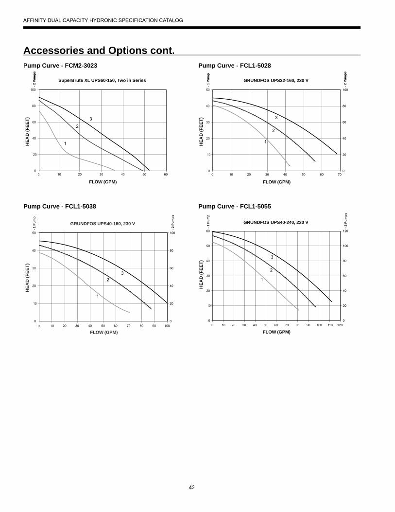
42
HEA
D (F
EET)
FLOW (GPM)
SuperBrute XL UPS60-150, Two in Series
- 2 P
umps
3
1
2
10 20 30 40 50 60 0
100
80
60
40
20
0
Pump Curve - FCL1-5028
Pump Curve - FCL1-5038H
EAD
(FEE
T)
FLOW (GPM)
GRUNDFOS UPS32-160, 230 V
- 1 P
ump
- 2 P
umps
3
1
2
100
10
20 30 40 50 70 60 0
80
60
40
20
0
50
40
30
20
10
0
HEA
D (F
EET)
FLOW (GPM)
GRUNDFOS UPS40-160, 230 V
- 1 P
ump
- 2 P
umps
100
10
20 30 40 50 70 60 0
80
60
40
20
80 90 100 0
50
40
30
20
10
0
1
2 3
Pump Curve - FCL1-5055H
EAD
(FEE
T)
FLOW (GPM)
3
1
2
100
10 20 30 40 50 70 60 0
80
60
40
20
80 90 100
120
110 120
GRUNDFOS UPS40-240, 230 V
0
50
40
30
20
10
60
0
- 1 P
ump
- 2 P
umps
Pump Curve - FCM2-3023
Accessories and Options cont.p
AFFINITY DUAL CAPACITY HYDRONIC SPECIFICATION CATALOG
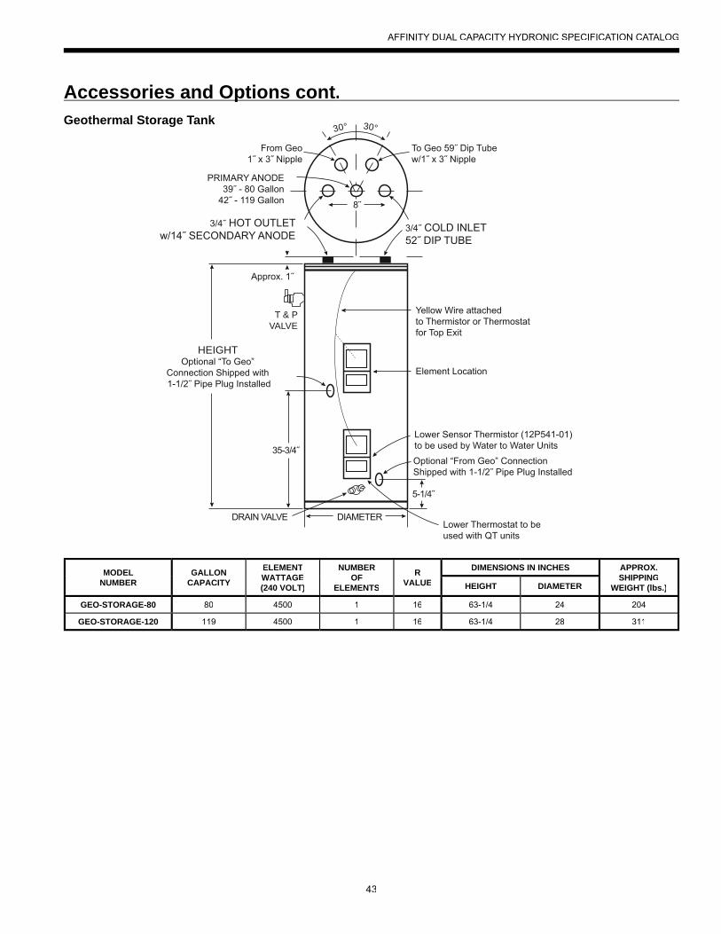
43
Geothermal Storage Tank30° 30°
T & PVALVE
HEIGHT
MODELNUMBER
GALLONCAPACITY
ELEMENTWATTAGE(240 VOLT)
NUMBEROF
ELEMENTS
RVALUE
DIMENSIONS IN INCHES APPROX.SHIPPING
WEIGHT (lbs.)HEIGHT DIAMETER
GEO-STORAGE-80 80 4500 1 16 63-1/4 24 204
GEO-STORAGE-120 119 4500 1 16 63-1/4 28 311
Accessories and Options cont.p
AFFINITY DUAL CAPACITY HYDRONIC SPECIFICATION CATALOG
44
Engineering Guide Specifi cationsg g pGeneralThe liquid source water-to-water heat pump shall be a single packaged reverse-cycle heating/cooling unit. The unit shall belisted by a nationally recognized safety-testing laboratory or agency, such as ETL Testing Laboratory, Underwriters Laboratory (UL), or Canadian Standards Association (CSA). The unit shall be rated in accordance with Air Conditioning, Heating, andRefrigeration Institute/International Standards Organization (AHRI/ISO) and Canadian Standards Association (CSA-US). The liquidsource water-to-water heat pump unit shall be designed to operatewith source liquid temperatures between 30°F [1.1°C] and 110°F [43.3°C] in cooling, and between 30°F [-1.1°C] and 90°F [32.2°C]in heating.
Casing and CabinetThe cabinet shall be fabricated from heavy-gauge galvanizedsteel and finished with corrosion-resistant powder coating. Thiscorrosion protection system shall meet the stringent 1,000 hour salt spray test per ASTM B117. The interior shall be insulated with1/2˝ thick, multi-density, coated glass fiber for noise suppression.
The control box shall have separate holes and knockouts for entrance of line voltage and low voltage control wiring. All factory-installed wiring passing through factory knockouts and openings shall be protected from sheet metal edges at openings by plasticferrules. The control box shall be field switchable from front to back for improved application flexibility with quick attach low voltageharnesses. The control box is shipped standard on the oppositeend of the water connections.
Refrigerant CircuitAll units shall contain two (2) sealed refrigerant circuits, eachcontaining a hermetic motor scroll compressor, bidirectional thermal expansion valve assemblies, reversing valve, braze plate heat exchangers, factory installed high and low pressuresafety switches, freeze detection, service ports, and liquid linefilter dryers. Compressors shall be scroll types designed for heat pump duty with internal isolation and mounted on rubber vibration isolators. Compressor motors shall have internaloverload protection. A high density sound attenuating blanketshall be factory installed around the compressor to reducesound. The water to refrigerant heat exchangers shall beinterlaced copper brazed, 316 stainless plate steel, capable of withstanding 650 psig [4489 kPa] working pressure on the refrigerant side and 450 psig [3108 kPa] on the water side.The thermal expansion valve assembly shall provide proper superheat over the liquid temperature range with minimal“hunting.” The assembly shall operate bidirectionally without theuse of check valves. Externally mounted pressure controlled water regulating flow valves are not acceptable.
Piping and ConnectionsSupply and return water connections shall be 2 in. [50.8 mm] FPT copper fittings fixed to the cabinet by use of a captive fitting, whicheliminates the need for backup pipe wrenches.
Optional Back/Top Mount Water Connections - shall be lfactory installed to the back corner post or top panel by use of a captive fitting, which eliminates the need for backuppipe wrenches.
WARNING: Warranty is void if strainers are not used on the entering side of the load and source.
ElectricalControls and safety devices will be factory wired and mountedwithin the unit. Controls shall include 24 Volt activated compressor contactors, 24VAC-75VA transformer with built in circuit breaker, reversing valve coils, and anti short-cycle protection. A terminalblock with screw in terminals will be provided for field control wiring.To prevent short cycling when the safety controls are activated, thereset relay shall provide a lockout circuit that requires resetting of low voltage supply or main circuit breaker. A lockout signal shall be provided to the display to indicate a lockout situation. Unitsshall be name-plated for use with time delay fuses or HACR circuitbreakers. Unit controls shall be 24 Volt and provide heating or cooling as required by the remote thermostat/sensor.
Optional GeoStart (Compressor Soft Starter) - shall be lfactory installed for use in applications that require low starting amps, reduced compressor start-up noise, off-grid, and improved start-up behavior. GeoStart shall reduce normalstarting current by 60% on 208/60/1 units.
Microprocessor ControlThe unit shall be controlled using an FX10 microprocessor which sequences all functions and modes of operations. The control shall interface with a (Y,B) thermostat, mechanical or electronic. The control shall have the ability to communicate with N2 Open, BacNet, or LonWorks protocols with optional communication card.The control system shall have the following features:1. Anti-short cycle time delay on compressor operation, time delay
shall be a minimum of 3 minutes2. Random start on power up mode3. Low voltage protection4. High voltage protection5. Unit shutdown on high or low refrigerant pressures6. Unit shutdown for low water temperature7. Source and Load heat exchanger low water temperature cutout
selectable for water or anti-freeze8. Automatic intelligent reset (Unit will automatically reset 5
minutes after trip if the fault has cleared. Should a fault reoccur 3 times sequentially then permanent lockout will occur.)
AFFINITY DUAL CAPACITY HYDRONIC SPECIFICATION CATALOG
45
Engineering Guide Specifi cations cont.g g p9. A 4 x 20 digit backlit LCD to display the following:
a. Entering and leaving water temperatures b. High pressure, low pressure, low voltage, high voltage, low water temperature cutout, and control status
10. The low pressure shall not be monitored for the first 120seconds after a compressor start command to preventnuisance safety trips.
11. Remote fault indication on the thermostat12. An accessory relay output tied to each compressor selectable
for normally open or normally closed
Optional N2 Open, BacNet or LonWorks - Units shall havelall the features listed above and the control board will be supplied with a interface card of choice. This will permit allunits to be daisy chain connected by a 2-wire twisted pair shielded cable. The following points must be available at a central or remote computer location:
• Source leaving water temperature• Load leaving water temperature• Emergency shutdown command• Cooling command• Heating command
AccessoriesFlow Proving SwitchP/N - FPS300A flow proving switch shall be available utilizing high reliability flow sensing technology.
Strainer Connection KitP/N - CKNDW1A strainer connection kit shall be available and includes a 2 in.[50.8 mm] Y-strainer with self-aligning screen and 1 in. [25.4 mm] blow-off port to reduce debris that will enter the heat exchanger. Strainers should be made of a brass body with a 316 stainless steel screen. Connection kit shall also include a 2 in. [50.8 mm]wrought copper tee with integral pressure/temperature port.
Strainer Hose Kit SetP/N - HHK162SA strainer hose kit set shall be available and includes a 2 in. strainer loaded with 20-40 mesh screen and blow down valve, 2in. stainless steel braid hose, 2 in. ball valve with integral pressure/temperature port and a JIC swivel fitting on the supply and 2 in. stainless steel braid hose and 2 in. ball valve with integralpressure/temperature port and a JIC swivel fitting on the return hose. The hose kit assembly shall be pressure rated at 300 psiworking pressure.
NOTE: A strainer kit is required on both sides to reduce heatexchanger fouling and potential damage.
AFFINITY DUAL CAPACITY HYDRONIC SPECIFICATION CATALOG

46
Revision GuidePages: Description: Date: By:
All First Published 19 Jun 2013 DS
AFFINITY DUAL CAPACITY HYDRONIC SPECIFICATION CATALOG


©2013 The manufacturer has a policy of continual product research and development and reserves the right to change design and specifi cations without notice.
Product: Affi nity SeriesType: Geothermal Hydronic Heat PumpsSize: 8-15 Ton Dual Capacity
Document Type: Specifi cation CatalogPart Number: SC1007WK6Release Date: 06/13
York and Affi nity are registered trademarks of Johnson Controls, Inc., and are used with permission.