Embed Size (px)
Citation preview
Energy Efficient BuildingsHeat Gain/Loss through Infiltration
Infiltration is air leakage into a building. Exfiltration is air leakage out of a building. By
continuity, mair,in=mair,out and it is common practice to refer to all air leakage as “infiltration”.
Infiltration DriversThe primary drivers of infiltration in buildings are stack effect, wind effect, combustion effect, exterior ducts, unbalanced supply and return air. These effects are discussed below.
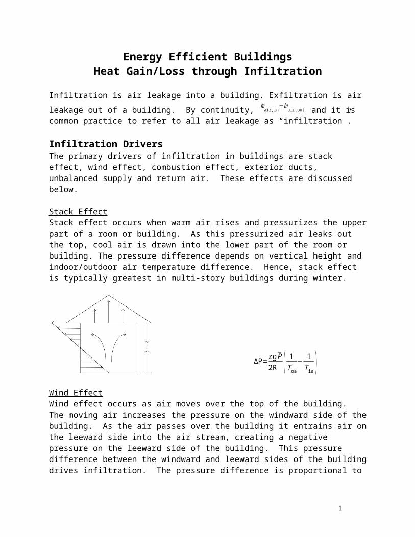
Stack EffectStack effect occurs when warm air rises and pressurizes the upper part of a room or building. As this pressurized air leaks out the top, cool air is drawn into the lower part of the room or building. The pressure difference depends on vertical height and indoor/outdoor air temperature difference. Hence, stack effect is typically greatest in multi-story buildings during winter.
ΔP=
zg P2R ( 1
T oa−
1T ia )
Wind EffectWind effect occurs as air moves over the top of the building. The moving air increases the pressure on the windward side of the building. As the air passes over the building it entrains air on the leeward side into the air stream, creating a negative pressure on the leeward side of the building. This pressure difference between the windward and leeward sides of the building drives infiltration. The pressure difference is proportional to the square of wind velocity V; hence wind effect is typically greater during winter when wind speeds are higher.
ΔP= ρ v2
2
1
PH PL
V V
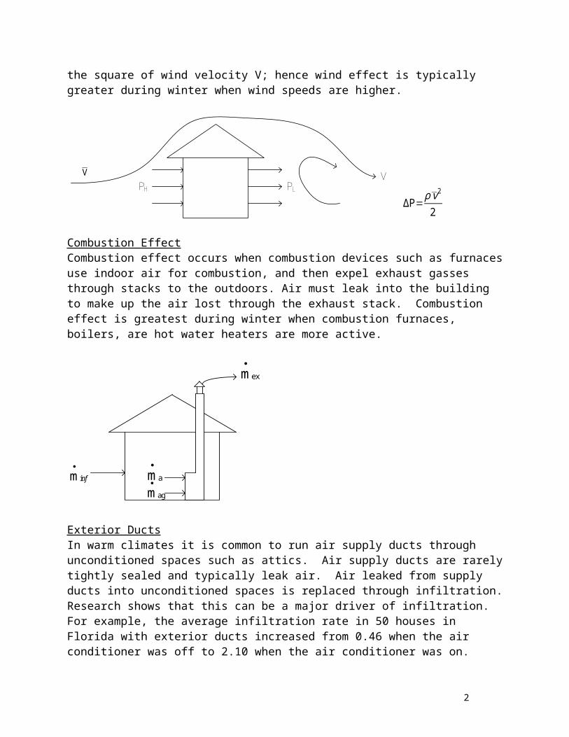
Combustion EffectCombustion effect occurs when combustion devices such as furnaces use indoor air for combustion, and then expel exhaust gasses through stacks to the outdoors. Air must leak into the building to make up the air lost through the exhaust stack. Combustion effect is greatest during winter when combustion furnaces, boilers, are hot water heaters are more active.
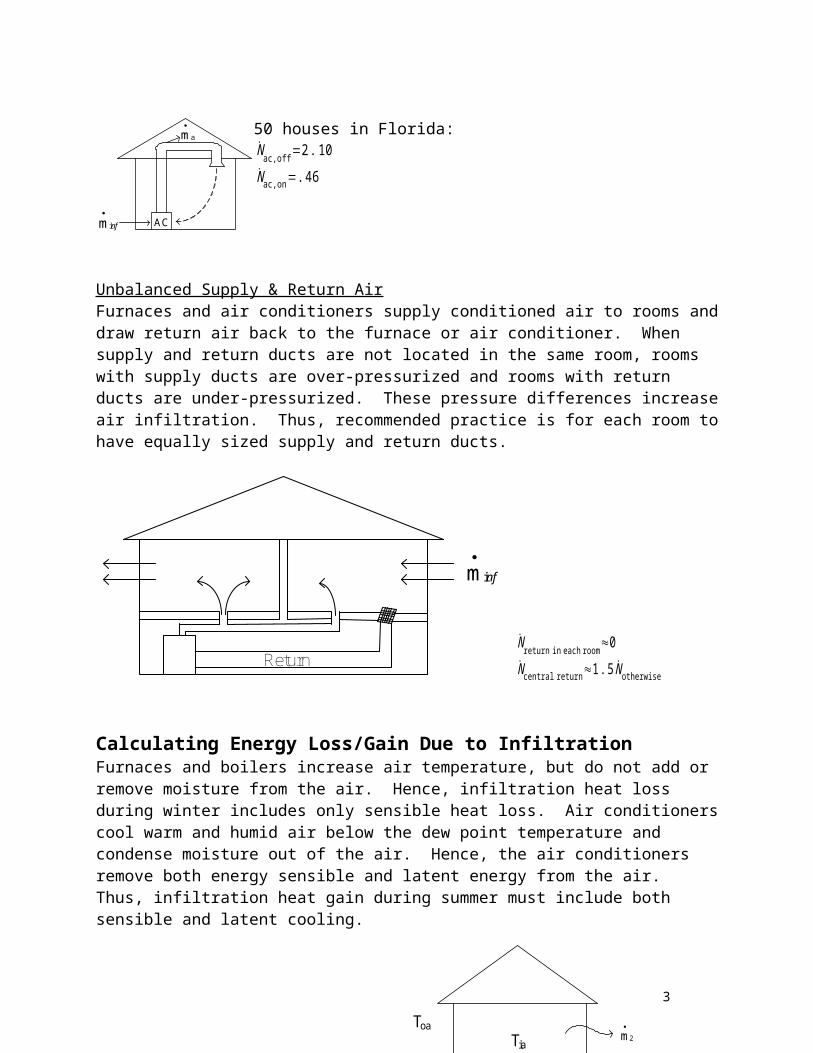
Exterior DuctsIn warm climates it is common to run air supply ducts through unconditioned spaces such as attics. Air supply ducts are rarely tightly sealed and typically leak air. Air leaked from supply ducts into unconditioned spaces is replaced through infiltration. Research shows that this can be a major driver of infiltration. For example, the average infiltration rate in 50 houses in Florida with exterior ducts increased from 0.46 when the air conditioner was off to 2.10 when the air conditioner was on.
50 houses in Florida:Nac,off=2. 10Nac,on=. 46
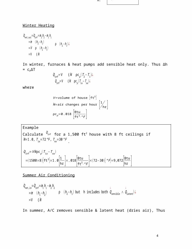
Unbalanced Supply & Return AirFurnaces and air conditioners supply conditioned air to rooms and draw return air back to the furnace or air conditioner. When supply and return ducts are not located in the same room, rooms with supply ducts are over-pressurized and rooms with return ducts are under-pressurized. These pressure differences increase air infiltration. Thus, recommended practice is for each room to have equally sized supply and return ducts.
2
am
nfim
AC
exm
nfim
am
agm
N return in each room≈0Ncentral return≈1 .5 Notherwise
Calculating Energy Loss/Gain Due to InfiltrationFurnaces and boilers increase air temperature, but do not add or remove moisture from the air. Hence, infiltration heat loss during winter includes only sensible heat loss. Air conditioners cool warm and humid air below the dew point temperature and condense moisture out of the air. Hence, the air conditioners remove both energy sensible and latent energy from the air. Thus, infiltration heat gain during summer must include both sensible and latent cooling.
Winter Heating
Qnet,out=Q inf=m2h2−m1h1
=m (h2−h1 )=V ρ (h2−h1 )=V { N
ρ (h2−h1 ) ¿
In winter, furnaces & heat pumps add sensible heat only. Thus Δh = cpΔT
Qinf=V { N ρcp (T2−T 1 )¿
Qinf=V { N ρcp (T ia−T oa )¿where
V=volume of house [ft3 ]N=air changes per hour [1 hr ]ρc p=0.018 [Btu
ft3⋅° F ]Example
Calculate Qinf for a 1,500 ft2 house with 8 ft ceilings if N=1 .0, T ia=72 °F, T oa=30 ° F .
3
1m
2m
Tia
Toa
Return
nfim
Qinf=V N ρcp (T ia−T oa )
=(1500×8 )[ft3 ]×1.0[1hr ]×.018 [Btuft3⋅° F ]×(72−30 ) [° F ]=9,072[Btu
hr ]Summer Air Conditioning
Qnet,in=Qinf=m1h1−m2h2
=m ( h1−h2 )=V { N
ρ (h2−h1 ) but h includes both Q¿
sensible ∧ Q¿
latent) ¿
In summer, A/C removes sensible & latent heat (dries air), Thus
Qinf=Qinf,sensible+Q inf,latent
Qinf,sensible=V { N ρc p(T 1−T2)=V { N ρc p(T oa−T ia) ¿ Q inf,latent=energy required to condense water from cooling coil ¿ =mwhfg=ma (ω1−ω2) hfg ¿ =V { N ¿ ρ (ω1−ω2 ) hfg ¿¿
where
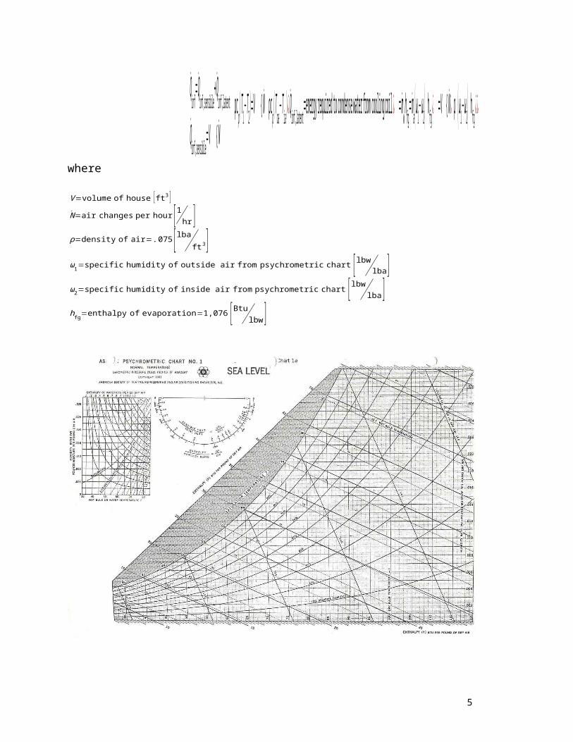
V=volume of house [ft3 ]N=air changes per hour [1 hr ]ρ=density of air=.075 [ lba
ft3]ω1=specific humidity of outside air from psychrometric chart [ lbw
lba ]ω2=specific humidity of inside air from psychrometric chart [ lbw
lba ]hfg=enthalpy of evaporation=1,076 [Btu
lbw ]
4
Example
Calculate the sensible & latent infiltration loads on a 1,500 ft2 house with 8 ft ceilings if
N=1 .0[1hr ] , T ia=70 °F, RHin=50%, T oa=90 °F, RHoa=80%
From the psychrometric chart:
ωia (T=70°F, RH=50% )=. 0078 [ lbwlba ]
ωoa (T=90 °F, RH=80%)=. 0248 [lbwlba]
Qinf,sensible=V { N ρc p (T oa−T ia ) ¿ =(1500×8 ) [ft3 ]×1 . 0[1hr ]×. 018[Btuft3⋅° F ]× (90−70 ) [° F ]=4,320[Btu
hr ] ¿¿
5
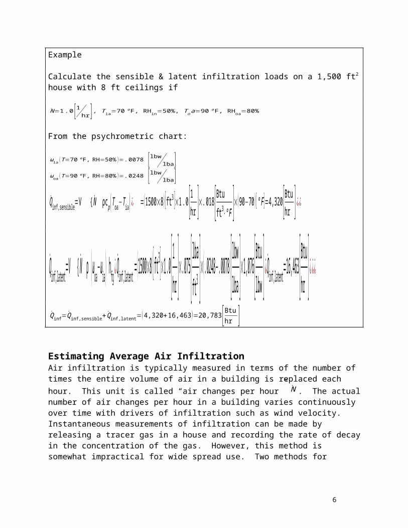
Qinf,latent=V { N ρ (ωoa−ωia ) hfg ¿ Q inf,latent =(1500×8 ) [ft3]×1 . 0[1hr ]×. 075[lbaft3 ]× (. 0248−.0078 ) [ lbw
lba ]×1,076 [Btulbw ] ¿ Q inf,latent=16,463[Btu
hr ] ¿ ¿¿
Qinf=Qinf,sensible+Q inf,latent=(4,320+16,463 )=20,783[Btuhr ]
Estimating Average Air Infiltration Air infiltration is typically measured in terms of the number of times the entire volume of air in a building is replaced each hour. This unit is called “air changes per hour” N . The actual number of air changes per hour in a building varies continuously over time with drivers of infiltration such as wind velocity. Instantaneous measurements of infiltration can be made by releasing a tracer gas in a house and recording the rate of decay in the concentration of the gas. However, this method is somewhat impractical for wide spread use. Two methods for estimating the average number of air changes per hour are described below.
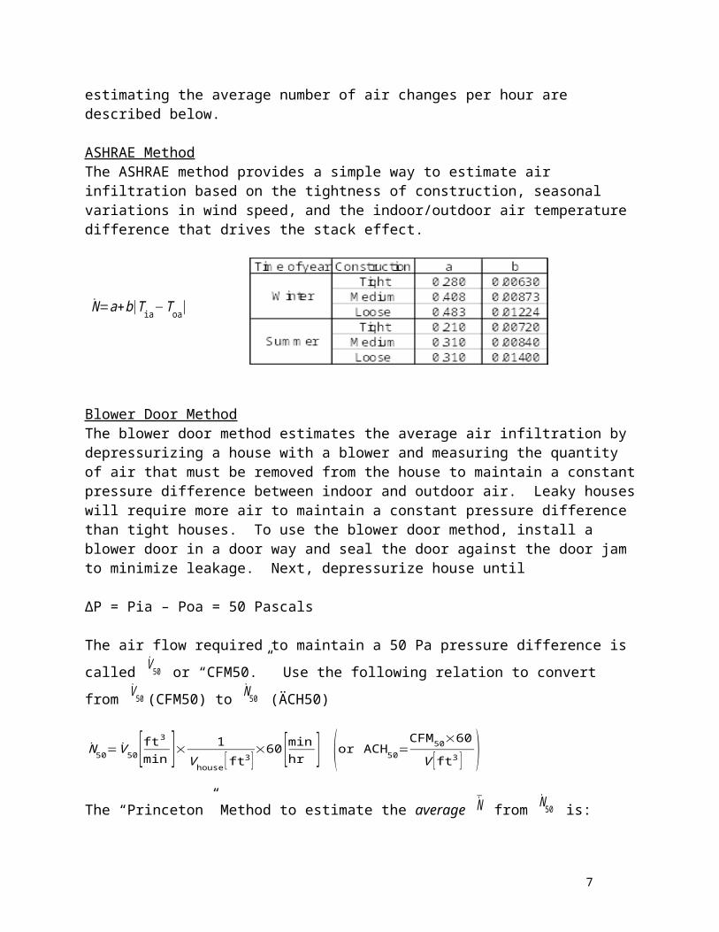
ASHRAE MethodThe ASHRAE method provides a simple way to estimate air infiltration based on the tightness of construction, seasonal variations in wind speed, and the indoor/outdoor air temperature difference that drives the stack effect.
N=a+b|T ia−T oa|
Blower Door MethodThe blower door method estimates the average air infiltration by depressurizing a house with a blower and measuring the quantity of air that must be removed from the house to maintain a constant pressure difference between indoor and outdoor air. Leaky houses will require more air to maintain a constant pressure difference than tight houses. To use the blower door method, install a blower door in a door way and seal the door against the door jam to minimize leakage. Next, depressurize house until
ΔP = Pia – Poa = 50 Pascals
6
The air flow required to maintain a 50 Pa pressure difference is called V 50 or “CFM50.” Use the
following relation to convert from V 50 (CFM50) to N50 (ÄCH50)
N50=V 50 [ft3
min ]× 1V house [ ft3 ]
×60[minhr ] (or ACH50=
CFM50×60
V [ft3 ] )The “Princeton” Method to estimate the average N from N50 is:
N=N50
20 (or ACH=ACH50
20 )The “Sherman” Method to estimate the average N from N50 is:
N=N 50
C×H×S×L (or ACH=ACH50
C×H×S×L )where the following coefficients can be estimated from the graph and tables that follow.
C = leakage infiltration ratio: 26 (hot climate) < C < 14 (cold climate)H = height correction factorS = wind shielding correction factorL = leakiness correction factor
7
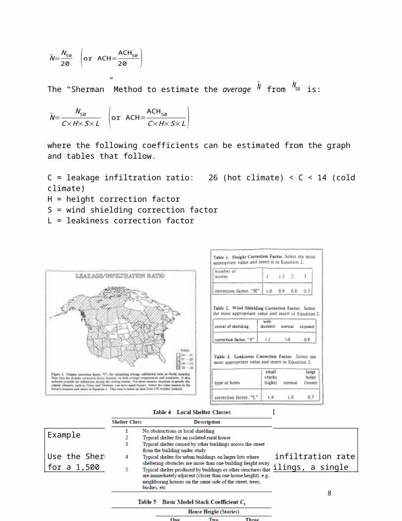
Coefficients for Sherman Method
Example
Use the Sherman method to calculate the average infiltration rate for a 1,500 ft2 house in Dayton, OH with 8 ft ceilings, a single story, average shielding, and average cracks, if the measured CFM50 = 1,800 cfm.
N50=ACH50=CFM50
V [ft3] [ft3
min ]×60[minhr ]=1800×60
1500×8=9 . 00 [1hr ]
N=ACH=ACH50
C×H×S×L=9 . 00
20×1.0×1. 0×1 .0=. 45 [1hr ]
LBNL Effective Air Leakage AreaThe LBNL method calculates an effective air leakage area, AL, at 0.016 inwc from a blower door test. The air flow due to infiltration is then calculated as:
Q = AL (Cs (Tia-Toa) + Cw U2)0.5
Where Cs is stack coefficient, Cw is wind coefficient and U is wind speed. Values of these coefficients are listed in the tables below.
Source: ASHRAE Fundamentals, 2005 p. 27.21
Typical Air Infiltration RatesAn independent study of air infiltration rates in new Minnesota houses found average rates of ACH50 = 4.2 and ACH = 0.27. ASHRAE research shows that 75% of newly constructed homes have infiltration rates between 0.25 and 0.75 air changes per hour. Older homes have higher infiltration rates.
8
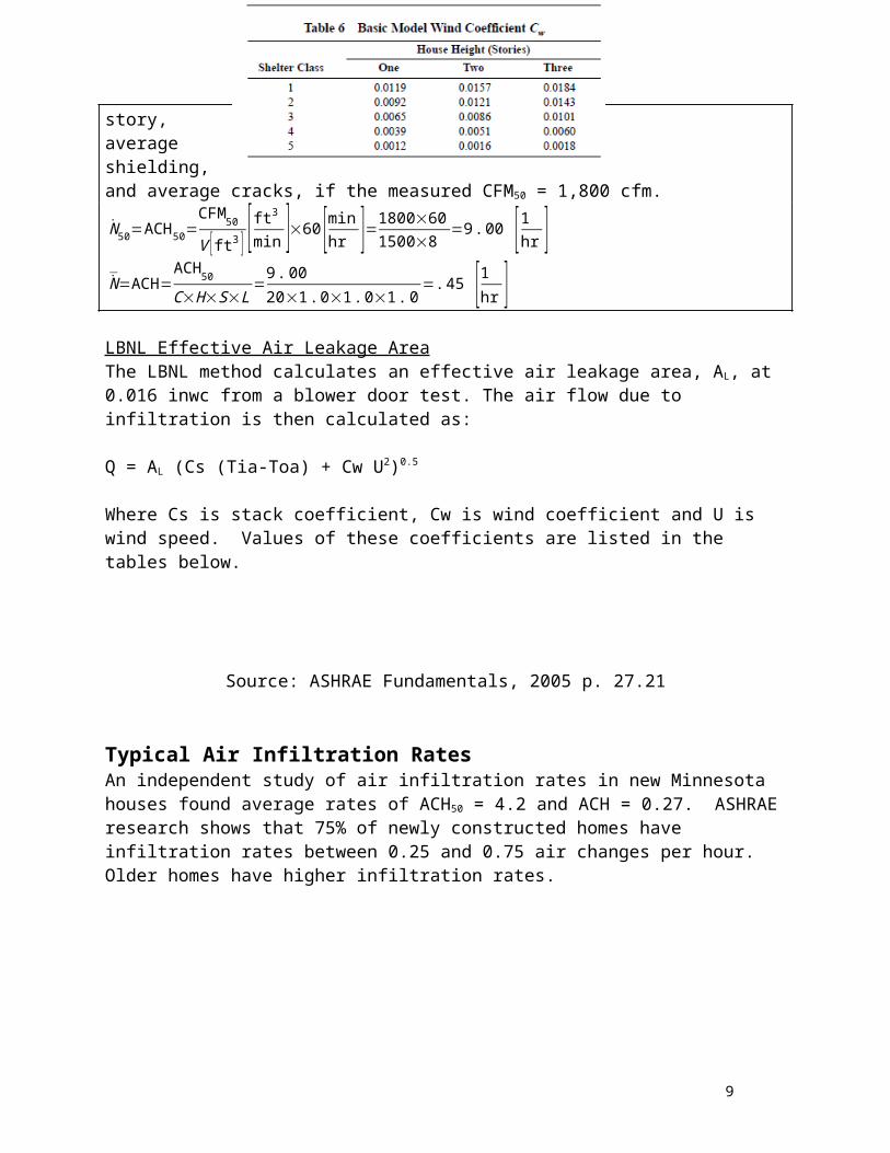
Source: ASHRAE Fundamentals, 2005 p. 27.15
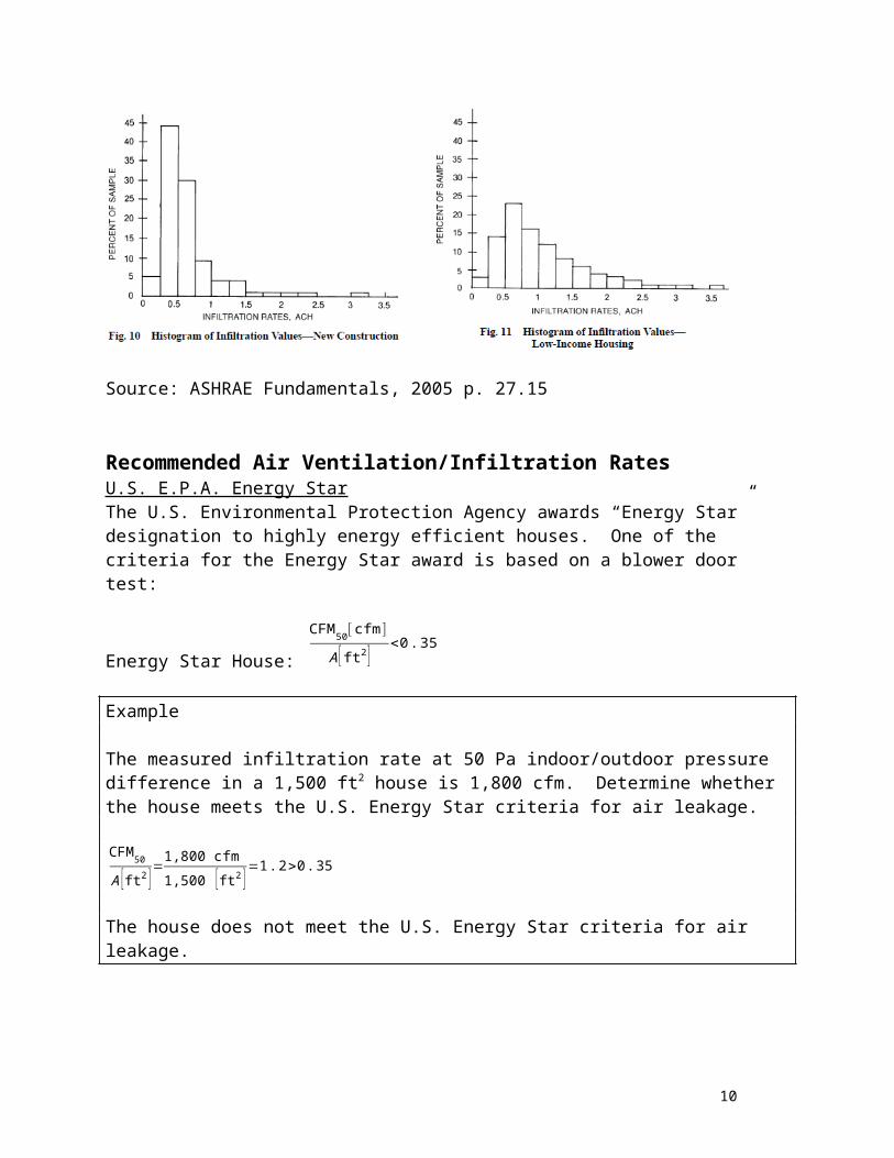
Recommended Air Ventilation/Infiltration RatesU.S. E.P.A. Energy StarThe U.S. Environmental Protection Agency awards “Energy Star” designation to highly energy efficient houses. One of the criteria for the Energy Star award is based on a blower door test:
Energy Star House:
CFM50 [ cfm ]
A [ft2 ]<0 .35
Example
The measured infiltration rate at 50 Pa indoor/outdoor pressure difference in a 1,500 ft2 house is 1,800 cfm. Determine whether the house meets the U.S. Energy Star criteria for air leakage.
CFM50
A [ft2]=1,800 cfm
1,500 [ft2]=1.2>0 . 35
The house does not meet the U.S. Energy Star criteria for air leakage.
ASHRAE Standard 62-1989ASHRAE Standard 62-1989 recommends that all houses have ventilation rates exceeding 0.35 ACH to remove air contaminants. Thus, in very tight houses in which the natural infiltration rate is less than 0.35 ACH, recommended practice is to install an air-to-air heat exchanger, which continually brings in and exhausts outdoor air but recovers energy between the two air streams.
9
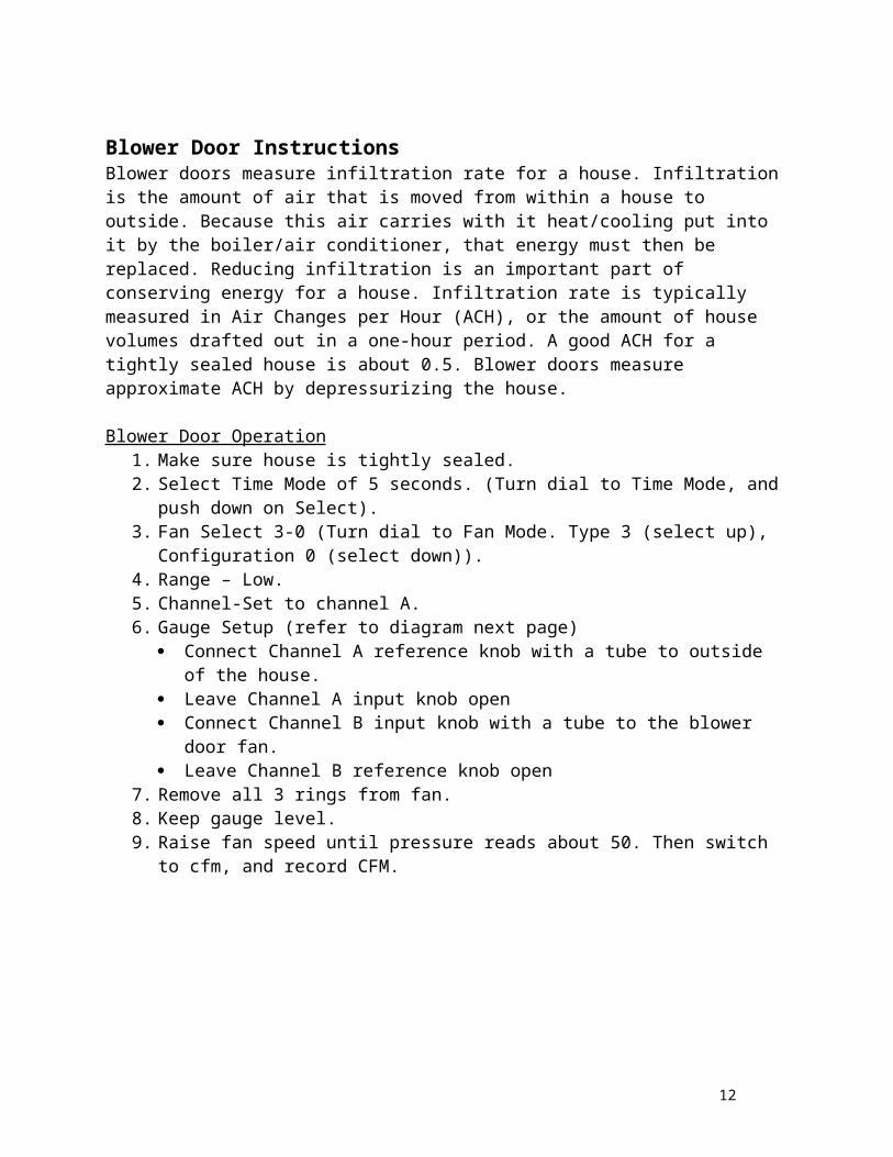
Blower Door InstructionsBlower doors measure infiltration rate for a house. Infiltration is the amount of air that is moved from within a house to outside. Because this air carries with it heat/cooling put into it by the boiler/air conditioner, that energy must then be replaced. Reducing infiltration is an important part of conserving energy for a house. Infiltration rate is typically measured in Air Changes per Hour (ACH), or the amount of house volumes drafted out in a one-hour period. A good ACH for a tightly sealed house is about 0.5. Blower doors measure approximate ACH by depressurizing the house.
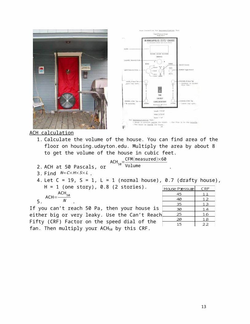
Blower Door Operation1. Make sure house is tightly sealed.2. Select Time Mode of 5 seconds. (Turn dial to Time Mode, and push down on Select).3. Fan Select 3-0 (Turn dial to Fan Mode. Type 3 (select up), Configuration 0 (select down)).4. Range – Low.5. Channel-Set to channel A.6. Gauge Setup (refer to diagram next page)
Connect Channel A reference knob with a tube to outside of the house. Leave Channel A input knob open Connect Channel B input knob with a tube to the blower door fan. Leave Channel B reference knob open
7. Remove all 3 rings from fan.8. Keep gauge level.9. Raise fan speed until pressure reads about 50. Then switch to cfm, and record CFM.
10
ACH calculation1. Calculate the volume of the house. You can find area of the floor on
housing.udayton.edu. Multiply the area by about 8 to get the volume of the house in cubic feet.
2. ACH at 50 Pascals, or ACH50=
CFM(measured )×60Volume .
3. Find N=C×H×S×L .4. Let C = 19, S = 1, L = 1 (normal house), 0.7 (drafty house), H = 1 (one story), 0.8 (2
stories).
5.ACH=
ACH50
N .If you can’t reach 50 Pa, then your house is either big or very leaky. Use the Can’t Reach Fifty (CRF) Factor on the speed dial of the fan. Then multiply your ACH50 by this CRF.
Example EEB Infiltration Measurements229 Lowes
Built ~1930Vol. = 14,120 ft3
CFM50 = 5704dP = 45 Pa (therefore factor of 1.1) Fan dP = 143 Pa;
ACH50=CFM50×60Volume
=24 . 21
N=ACH50
20=1 . 21
(Princeton Method)
435 Kiefaber
(Built 1999)Vol. = 15,683 ft3
CFM50 = 3255 Total dP = 50 PaFan dP = 46 Pa;
ACH50=CFM50×60Volume
=12 .45
N=ACH50
20=. 62
(Princeton Method)
11
Minimizing Infiltration Losses in Energy Efficient Buildings
Create Wind Shields Build an earthen berm, locate the garage, or plant trees and shrubs on the windward side of a building to shield it from the wind.
Supply Outside Air to Combustion Devices Use PVC piping to directly supply outside air for combustion to natural gas furnaces, boilers and water heaters. This will reduce drafts of cold air directly into the conditioned space.
Seal Air LeaksProbably the single most cost effective measure to improve energy efficiency is sealing leaks.
In new construction, the goal is to create a continuous air barrier. Typically this entails sealing joints between the foundation, sill plate, floor joist header, sub-floor, wall framing plates and upper rim joist. In addition, seal all penetrations in the wall and ceiling drywall including electrical boxes and plumbing. Finally, tape and seal all joints in the house wrap and moisture barriers. One study found that at 50 P pressure difference, air leakage in a sealed house averaged 1.24 air changes per hour compared with 2.41 air changes per hour in an identical but unsealed house (1).
In existing buildings, use weatherstripping to seal doors and windows. Felt and open cell foam are inexpensive. However, vinyl and metal weatherstripping tends to last longer and be more effective at reducing air flow. Use caulk to seal joints around plumbing and electrical fixtures and between walls, floors, ceilings, windows and doors. Also,
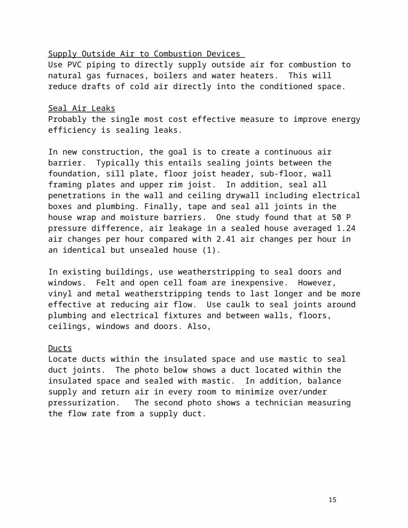
DuctsLocate ducts within the insulated space and use mastic to seal duct joints. The photo below shows a duct located within the insulated space and sealed with mastic. In addition, balance supply and return air in every room to minimize over/under pressurization. The second photo shows a technician measuring the flow rate from a supply duct.
12
Photos: NREL. http://www.nrel.gov/data/pix/
Air-to-Air Energy Recovery UnitsTo minimize heating and cooling energy losses associated with exhausting and replenishing outdoor air, heat can be exchanged between the entering and exiting air streams. All air-to-air energy recovery units transfer sensible heat from the warm air stream to the cool air stream, raising the temperature of the cool air stream and lowering the temperature of the hot air stream. Some air-to-air energy recovery units can also transfer latent heat, in the form of water vapor, between the air steams. In these units, moisture is transferred from the moist air stream to the dry air stream. In an air-conditioned building when the indoor air is dryer than the outdoor air, this decreases the humidity of air entering the building.
The schematic below shows an energy recovery unit that uses a heat exchange wheel. As the wheel slowly rotates through the hot side, fins within the wheel absorb heat from air and cool the exit air. When the fins rotate to the cool side, they give up this heat and heat the exit air. The performance of a typical sensible+latent air-to-air heat exchanger is depicted in the schematic. The picture below shows a different type an energy recovery unit with a fixed plate heat exchanger. One air stream is drawn diagonally from upper left to lower right. The other air stream is drawn diagonally from lower left to upper right. Sensible heat is transferred through plates between the two air streams.
Source of data: http://www.airxchange.com/
13
OUTDOOR AIR95°F DB78°F WB
EXHAUST AIR89°F DB73°F WB
SUPPLY AIR81°F DB68°F WB
RETURN AIR75°F DB63°F WB
SUMMER CONDITIONS
OUTDOOR AIR7°F DB6°F WB
EXHAUST AIR27°F DB73°F WB
SUPPLY AIR53°F DB40°F WB
RETURN AIR72°F DB54°F WB
WINTER CONDITIONS
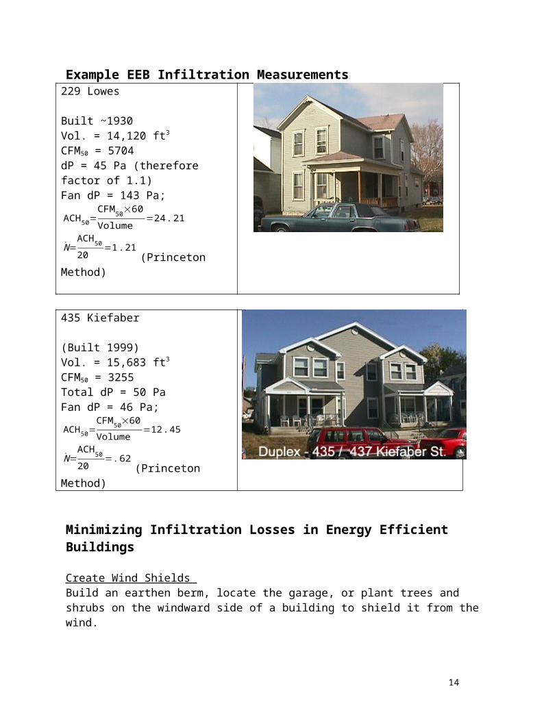
Photo: NREL. http://www.nrel.gov/data/pix/
Energy savings from air-to-air heat exchangers can be modeled using the heat exchanger effectiveness method as:
Sensible only: Q = e m cp (Th1 – Tc1) = e V (p cp) (Th1 – Tc1)Sensible + Latent: Q = e m (hh1 – hc1) = e V p (hh1 – hc1)
where e is heat exchanger effectiveness, m is mass flow rate, V is volume flow rate, p is density, cp is specific heat, T is temperature, h1 is the entering hot stream and c1 is the entering cold stream.
Example
Consider a sensible air-to-air heat exchanger moving 100 cfm into and out of a building with effectiveness = 0.70. The inside air temperature is 72 F and the outside air temperature is 30 F. The product of air density and specific heat, (p cp), is 0.018 Btu/ft3-F. Determine the energy reclaimed (Btu/hr) and the temperature of the pre-heated as it leaves the heat exchanger and enters the building.
The rate of heat reclaimed by the heat exchanger is:
Q = e V (p cp) (Th1 – Tc1) = 0.70 100 ft3/min 60 min/hr 0.018 Btu/ft3-F (72 – 30)Q = 3,175 Btu/hr
From an energy balance on the incoming cold air stream:
Q = V (p cp) (Tc2 – Tc1)Tc2 = Tc1 + Q / [ V (p cp) ] =30 F + 3,175 Btu/hr/[100 ft3/min 60 min/hr 0.018 Btu/ft3-F]Tc2 = 59.4 F
14
References :(1) (http://www.energysavers.gov/your_home/insulation_airsealing/index.cfm/
mytopic=11310).
15