Embed Size (px)
Citation preview

HEATH.7'11"6
TRI-POWER SUPPLY
Model SP-2718
595-1841-02
" I' 1 J1
__1
r""u..'~,L, __
r••L .....
o.""'-""J ."
HEATH COMPANY Copyright © 1976 BENTON HARBOR, MICHIGAN 49022
Heath Company All Rights Re.served
Page 2
TABLE OF CONTENTS
SPECIFICATIONS . . ... . ....... .. .. . . .. . .. . .. .. .. . . . . 3 CIRCUIT DESCRIPTION .. . .. . ... . . . . . . ... . . .. . ... 14
OPERATION .. . . . ...... . ............... . .. . . ...... .. 5
CONTROL AND SWITCH FUNCTIONS ... . . . . . . .... . . . 5
OPERATING PROCEDURES . .. .. . . .. .. .. . .. . . . . .. .. . 6
APPLICATIONS.. .. ... .. .. . ... .. . . .. ... . . . ... ..... 7 Circuit Board X-Ray View . . . . . . . ... . ....... . ... .. .. . . 20
Tracking Mode Applications . . . Schematic Diagram . . ... . .. .. .. .. . . .. .. .. . (Fold-in Page)
.... ... .. . .. . . .. . . .. . . 9
IN CASE OF DIFFICULTY .. . . .... .. ... . .. . ........ . . 10 General .. . . . .. . ... . ... . .. . . ... . ... . . .. .. . . " .. . .. . . 10
WARRANTY . ... . .. .. .. . . ... . . . .. . . . . Inside front cover
Primary Circuit . . . . . . . . . . . . . . . . . . . . . . . . . . . . . . . . . . .. 14 5-Volt Supply. . . . . . . . . . . . . . . . . . . . . . . . . . . . . . . . . . . . . 14 20-Volt 'A' and 'B' Supplies ...... . .. ... . . .... .. . . .. 15 Metering Circuit. . . . . . . . . . . . . . . . . . . . . . . . . . . . . . . . . . . 15
CALIBRATION .......... . ...... . ... ... .. . .. .... ... .16
APPENDIX ... . ........ . ... .. ........... . ..... . . . ... 18
Independent Mode Applications . . . . . . . . . . . . . . . . . . . . . . 7
Parts List .. . . ... . . ... ... . ... . ... . ... .. .... . . .. ..... 18
SERVICE INFORMATION ... . . .. .. . . . " Inside rear cover Troubleshooting Chart .. . ... ... . . . . . . ... . . .. .. ..12

Page 3
SPECIFICATIONS
Outputs . . ... . .. . ... .. . .. . . , .. . , .. . . . ... . , .... . .
'A' -Supply .. . . . . . .. . . . .. . .. .... .. . . . .. . . . .. .. . .
'8' -Supply .. .. . . . . . . . . . . .. . .. ...... . . . ..... . .. .
Regulation
Load . . . ..... . . . . ... . . .. . ... . . . . . . . . . .. . . . . . . .
Line .. . . . . . .. . . .... . . . ... " . ... .. .. ' " . . " . , .
Ripple and Noise . .. . . ... . .. . ...... . . . ... ... . . .
Current Limiting .. . . .. . .. . . . . ... .... . . . . .. .. . . . . .
Tracking Range .. . .. .. . . . .. .. . . . . . . . .. . ... . . . . . .
Tracking Error .. . . . . . . . . . . . . ........ . . . . . ... . .. . .
Series Operation ...... . . ... . . .... . . .. . . . . .... . . .
Parallel Operation . . .. . . . .. . .. . . .. . . .. .. . . . . . ... .
VOltage-Current Monitor Accuracy . .. .. . . .. ... . ... .
5 volts DC ::!:: 5% at 1.5 ampere.
0-20 volts DC at 0.5 ampere, continuously adj,ustable.
0-20 volts DC at 0.5 ampere, continuously adjustable.
Less than 0.1 % (20 mV) variation from no load to full load on 20-volt supplies.
Less than 3% (150 mV) variation from no load to full load on 5-volt supply.
20-volt Supplies : Less than 0.2% (40 mV) for a line voltage change of 10 volts.
5-volt Supply : Less than 0.2% (10 mV) for a line voltage change of 10 volts.
Less than 5 mV rms.
Limiting for each supply fixed slightly above rated current to provide short-circuit protection.
2 to 18 volts.
Less than 1 volt.
All three supplies may be connected in series.
20-volt supplies may be operated in parallel by adding 0.511 current-equalizing resistors (not supplied).
5% of full scale.

Page 4
Meter Ranges . . . ... . .... . .. ... .............. . . .
Power Requirements .. ... . . ... .. .. ... .. .. . . . . .. .
Power Switching Overshoot (On-Off) ... ... . . . . .. . .
Voltage Control, 20-Volt Supplies A and B . .. . . . . . . .
Dimensions . .. .. . . .. . .. . ..... . .. ... .. ... ... . . . . .
Weight ... .. .... . .. . . .. . . ... . ... . . ..... . .... . .. .
Voltages, 0-20 and 0-5.5. Current, 0-550 mA and 0-2A.
100-135 VAC or 200-270 VAC, 50/60 Hz, 100 watts at full load.
None.
Continuously variable, o to 20 volts.
4-1/2" high x 10-3/4" wide x 9" deep
(11.43 cm x 27.3 cm x 22 .86 cm).
10 Ibs (3.73 kg).
-The Heath Company reserves the right to discontinue products and to change specifications at any time without incurring any obligation to incorporate new features in products previously sold.

Page 5
OPERATION
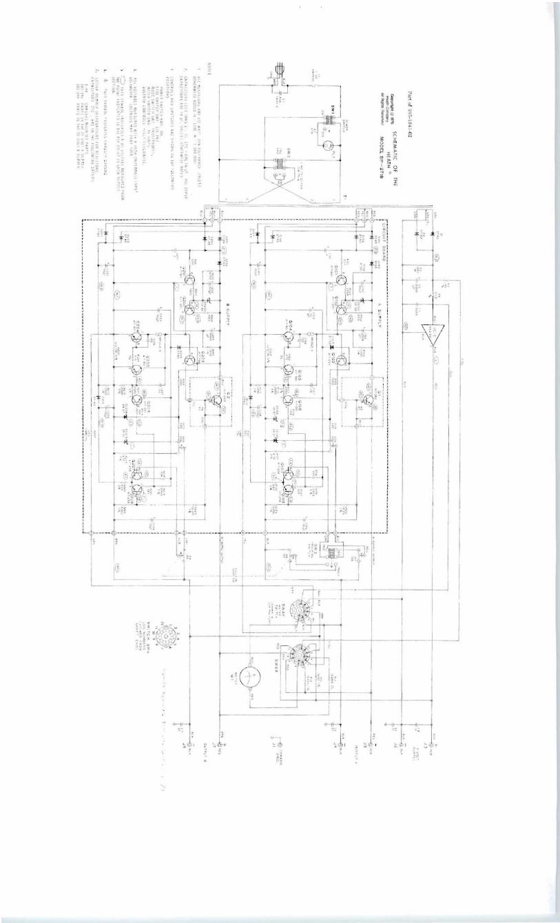
Refer to Figure 1 (on the fold-in).
Before you use your Tri-Power Supply, you should become entirely familiar with its capabilities, characteristics, and its features. Study Figure 1 to learn each control and switch function as you read this portion of the Manual.
CONTROL AN,o SWITCH FUNCTIONS
LINE AND POWER SWITCHES (SW2 and SW1)
Line switch SW2 is located on the underside of the chassis. If the line voltage in your area is 100-135 volts AC, use a screwdriver tip to push the switch slide to expose the "120" on the slide. If the line voltage in your area is 200-270 volts AC, push the switch slide to expose the "240."
The POWER switch on the front panel is a simple slide switch that applies the line voltage to the primary circuit of the power transformer when you push the switch to the ON position. At the same time, power is applied to the pilot light to indicate that power has been applied to the unit.
METER SWITCH (SW4)
It is important that you know that METER switch (SW4) does not switch any output voltage or current. The switch permits you to observe any of the Power Supply outputs on the meter, whether voltage or current. The METER switch thus allows you to monitor any of the variable outputs and to set them accurately to any desired levels.
METER
Note that the meter scales are printed in two colors. The lower scale, in red, corresponds to each of the METEr! switch functions that also are lettered in red : "A-AMPS" (current flowing to a load from the output of the A supply; uB-AMPS" (current flowing to a load from the output of the B supply; and, 5V-VOL TS (the voltage available at the output of the 5-volt supp.ly).
The l:Jpper meter scale, in black, corresponds to the following METER switch functions, also printed in black: "A-VOLTS"
(the voltage at the output of the A supply); "B-VOL TS" (the voltage at the output of the B supply); and, "5V-AMPS" (current flowing to a load from the output of the 5-volt supply) .
SUPPL Y A CONTROL (R7)
When you turn this control clockwise from its "0" position, the output of front panel jacks J4 and J5 (OUTPUT A) will increase from zero to any level up to 20 volts and a load current up to 500 milliamperes. Read these levels on the meter when the METER switch is either at "A-VOLTS" or at "A-AMPS." NOTE: In the TRACKING mode of operation, Supply A control R7 is disabled; control of the 20-volt A-supply is transferred to • A TRACKING B.control RS (the small red knob at the right side of the front panel, which operates as a clutched control with 0 SUPPLY B control R9) .
o SUPPLY B CONTROL (R9)
Control R9 is half of the dual control at the right side of the front panel. The other half of this control is turned with the small red knob and is labeled ". A TRACKING B" in red lettering above the two control knobs. The two controls are "clutched" together in such a manner that both controls will turn when either knob is turned. Note that black knob R9 corresponds to the black letters ("0 SUPPLY B") on the panel just above the control.
Control R9 adjusts the amount of voltage at OUTPUT B jacks J6 and J7. This control will vary the available B-supply voltage from zero to 20 volts DC and a load current up to 500 milliamperes. Read the output levels on the meter when the METER switch is turned to B-VOL TS and to B-AMPS.

Page 6
• A TRACKING B CONTROL (RS)
Control RS is "clutched" to "0 SUPPLY B" control A9. At any time either control is turned, the other will turn with it. Since it is a friction action, either control may be operated independently of the other, providing the other control is held in place. Control RS is enabled only when MODE switch SW3 is in the TRACKING position. In this manner, the A 20-volt supply is disabled at SUPPLY A control R7, and is controlled by the small red knob at RS. At no time are the electrical and electronic circuits of the A and B 20-volt power supplies connected together internally.
MODE SWITCH (SW3)
In the INDEPENDENT mode of operation, the 20-volt A supply is connected to SUPPLY A control R7 through the contacts of the Mode switch. In this mode, the A-supply is "floating" and control R9 (small red knob) is disconnected from the circuit. When MODE switch SW3 is in the TRACKING mode, control
A7 is removed from the circuit, and contro'l A9 is enabled and the A-supply will track with the B-supply through the clutch action of the dual control knobs.
OUTPUT JACKS (J1-J7)
Output jack J1 is a chassis ground connection. If, at any time, you wish to reference any of the three supplies to ground, external connections from the appropriate supply jacks may be connected to J 1 .
Jacks J2 and J3 are the connections for the fixed 5-volt, 1.5-ampere power supply.
Jacks J4 and J5 are the connections for the variable 20-volt, 500 milliampere A power supply.
Jacks J6 and J7 are the connections for the variable 20-volt, 500 milliampere B power supply.
OPERATING PROCEDURES
Two modes of operation are provided at the output jacks on the front panel. These are the "Independent" and the "Tracking" modes. Each will be discussed under separate headings.
INDEPENDENT MODE
Each of the three power supplies in the Tri-Power supply may be operated independently from one another, either floating or referenced to another AC or DC source, or referenced to the Tri-Power Supply ground connection at J1. In addition, any of the separate supplies may be connected in series with external jumpers to provide up to 45 volts DC, referenced to any external or internal level. NOTE: External references may not exceed 200 volts.
TRACKING MODE
In the TRACKING mode of operation, the 20-volt A and B supplies are clutched together at the front panel dual control RS/R9. As either of the controls is turned, the other will turn in
the same manner. To adjust the controls, the voltage output must be observed on the meter for each 20-volt supply, and the level of each set by controls AS and R9. For example, if you wish to have the A-supply referenced 5 vo.lts greater than the variable B-supply, you should proceed as follows : Turn dual controls R8 and R9 fully counterclockwise. Grasp the black knob at R9 and hold it as you turn the small red knob on R8 until A-VOLTS on the meter indicates +5 volts. Release the red knob. As you turn the black knob, the A-supply voltage will track the B-supply voltage, always at a potential of 5 volts (:t5%) higher than produced by the B-supply.
In the TRACKING mode, the A and B supplies may be operated in parallel as a tracking pair of output voltages, either referenced internally with jumpers, or to an external reference voltage not exceeding 200 volts. As in the INDEPENDENT mode, the three supplies may be connected as any combination in series, to supply up to 45 volts total at any desired reference.

Page 7
APPLICATIONS
The Tri-Power Supply is an ideal instrument for experimenters and engineers. As an example, at Heath Company an engineer developed a transistorized preamplifier circuit for which he needed supply voltages of - 16 volts DC and +16 volts DC in order to check out the circuit. Using the Tri-Power Supply, he connected A + to B-, and set the A and B supplies to 16 volts output. He then connected a jumper from the chassis GND reference to the common connection between the two supplies. In this manner, the A-supply output produced a -16 volts and the B-supply output produced +16 volts.
The following sections of the Manual will show you a number of examples of how you can use your Power Supply. The variety of uses is extensive, however, so only a few are given.
NOTE: Since 5 volts is used extensively in TTL logic applications, it is incorporated into the Tri-Power Supply as a fixed output. This 5 volts DC may be referenced to any other voltage up' to 200 volts, or to the Power Supply front panel GND jack at J1.
INDEPENDENT MODE APPLICATIONS
INDEPENDENT FLOATING SUPPLIES
Refer to Figure 2 as you read the following information.
Figure 2 illustrates each of the three Power Supply outputs connected to separate loads. Each of the supplies may be floated at a level up to 200 volts from ground, or from each other. In this example, the MODE switch is at INDEPENDENT; SUPPLY A control R7 controls the output level of one 0-20 volt circuit, and SUPPLY B (black) control R9 controls the output of the other 0-20 volt circuit.
Each of the supplies has fixed current Hmiting in all modes of operation at slightly above the rated current output. This provides infinite short-circuit protection to the Power Supply.
NOTE: Each circuit output has a .011LF capacitor connected from ,its negative terminal to chassis ground. The effect of this capacitance on the load circuit should be considered when you attempt to float any of the supplies at a level above chassis ground.
@m +oDbIQvQmQ+II I I I I
I I I I I I I I I I I I I I I I I I I I I I I I I I I I I I I I I I I I I I I I I I
1~ : LOAD I LOAD ~ ~ 0-500mA. 0-500mA .
Figure 2
Page 8
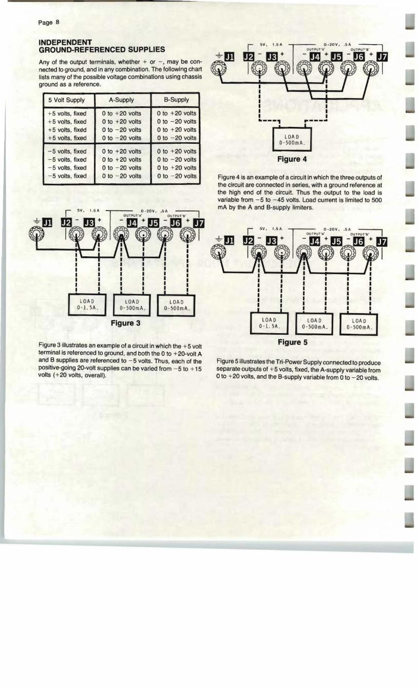
INDEPENDENT GROUND-REFERENCED SUPPLIES
Any of the output terminals, whether + or -, may be connected to ground, and in any combination. The following chart lists many of the possible voltage combinations using chassis ground as a reference.
I 5 Volt Supply A-Supply I B-Supply
+ 5 volts, fixed o to + 20 volts o to + 20 volts + 5 volts, fixed o to + 20 volts o to - 20 volts +5 volts, fixed o to - 20 volts o to + 20 volts + 5 volts, fixed o to - 20 volts o to - 20 volts
-5 volts, fixed o to + 20 volts o to + 20 volts -5 volts, fixed o to + 20 volts o to - 20 volts -5 volts, fixed o to - 20 volts o to + 20 volts -5 volts, fixed o to - 20 volts o to - 20 volts
. --I LOA D LOA D
O-SOOmA .I 0 - I.SA. LOAD
D- SOOmA.
Figure 3
Figure 3 illustrates an example of a circuit in which the + 5 volt terminal is referenced to ground, and both the 0 to + 20-volt A and B supplies are referenced to -5 volts. Thus, each of the positive-going 20-volt supplies can be varied from -5 to + 15 volts (+20 volts, overall).
.---~ r---~ r-Io--....
LOA D O- SODmA.
Figure 4
Figure 4 is an example of a circuit in which the three outputs of the circuit are connected in series, with a ground reference at the high end of the circuit. Thus the output to the load is variable from - 5 to -45 volts. Load current is limited to 500 mA by the A and B-supply limiters.
if ~Bt¥l~m<r?,'----I I 1 1 1 1
1 1 I 1 I I 1 I 1 I 1 1 I 1 I I 1 1 1 1 1 1 1 1 1 1 1 1 I 1 1 1
I I
I I I 1lit!
LOA D LOA D LOA D 0-1. SA . O-SOOmA. 0-500mA.
Figure 5
Figure 5 illustrates the Tri-Power Supply connected to produce separate outputs of + 5 volts, fixed, the A-supply variable from oto +20 volts, and the B-supply variable from 0 to -20 volts.

Page 9
TRACKING MODE APPLICATIONS
r- SV . 1 . SA 0-20V •.SAn @m ~omOI~m?~!m@+
I I I I I I I I I I I
i : fo . so", ~% I : : ,--..,.--~ I I .. -'I I ( NOT 5 U P P L I [D )
~~ ~~
Figure 6
NOTE: In the Tracking Mode of operation, as previously described, A-supply control is clutched to the B-supply control at R8/R9.
PARALLEL OPERATION
The purpose of connecting the two 20-volt power supplies in parallel is to provide higher current through the load. Figure 6 shows a typical Power Supply-to-Ioad connection in which up to 1 ampere of current is available to the load. Note that 0.5
ohm current-sharing resistors (not supplied) are used in the output connections. The output voltage of the circuit is reduced by the IR voltage drop across these equalizing resis-tors. Each supply is short-circuit and overload protected; either 20-volt supply may current-limit slightly before the other.
TRACKING-FLOATING CIRCUITS
NOTE: Each of the three power supplies is connected to a separate load as shown in Figure 7. Each supply is floating, and independent of reference levels. In this configuration, the MODE switch must be in TRACKING to produce the following outputs: 5 volts fixed and floating, B-supply 0 to +20 volts floating with the A-supply output floating, and tracking the B supply at any predetermined voltage differential. To create a tracking :t supply, the A+ terminal may be connected to the B- terminal, for example. The Power Supply may be wired in any manner of series connections of A, B, and 5-volt outputs in the Tracking mode.
@m ~Q.EQIQV~~ r I I I I I I I I I I I I I I I I I I II I I I I I I I I I I I I I I I I I I I I I I I
1~ : LOAD: ; LOAD
~ O-SOOmA . O-SOOmA .
Figure 7

Page 10
IN CASE OF DIFFICULTY
This part of the Manual will help you locate and correct any difficulty which might occur in your Power Supply. The information is divided into two sections. The first section, "General," contains suggestions of a general nature in the following areas :
A. Bench-testing precautions.
B. Repair techniques.
The second section consists of a "Troubleshooting Chart." It calls out specific problems that may occur and lists one or more conditions or components that could cause each difficulty. Capacitor C-numbers, transistor Q-numbers, etc., are identified in this chart by the same numbers that are used on the Schematic diagram. A "Circuit Board X-Ray View" (on Page 20) is also provided to help you locate the components.
NOTE: In an extreme case where you are unable to resolve a difficulty, refer to "Customer Service" information inside the rear cover of the Manual. Your Warranty is located inside the front cover.
GENERAL
BENCH TESTING
WARNING: The full AC line voltage and high voltage DC is present at several points in the Power Supply. Be careful to avoid personal shock when you work on the Power Supply. Refer to Figure 8.
• Be cautious when you test the transistors and integrated circuit. Although they have almost unlimited life when used properly, they are more susceptible to damage from excessive voltage and current than other circuit components.
• Do not short any terminals to ground when you make voltage measurements. If the probe should slip, for example, and short out a bias or voltage supply point, it may damage one or more components.
• Do not remove any components while the Power Supply line cord is connected to the AC outlet.
• When you make repairs to the Power Supply, make sure you eliminate the cause as well. as the effect of the trouble. If, for example, you should find a damaged resistor, be sure you find out what caused the resistor to become damaged. If the cause is not eliminated, the replacement resistor may also become damaged when the Power Supply is put back into operation.
• Refer to the X-Ray View on Page 20 and the "Schematic" to locate the various components.
• Use a high impedance-input voltmeter to make any voltage measurements.

Page 11
.. _---
Figure 8
REPAIR TECHNIQUES
Components
Faulty resistors or capacitors should first be clipped from component leads from the circuit board, heat the solder on the foiland allow the lead to fall out of the hole. Preshape the leads of the replacement part and insert them into the holes in the circuit board. Solder the leads to the foil and cut off the excess lead lengths.
Transistors can be removed in the same manner as previously described. The replacement transistor must be installed with its leads in the proper holes. Then quickly solder the leads to avoid heat damage. Cut off the excess lead lengths.
CAUTION: On several areas of the circuit boards, the foil patterns are quite narrow. When you unsolder a part for checking or replacement, avoid excessive heat while removing the part. A suction-type desoldering tool will make part removal easier.
Foil Repair
A break in a circuit board foil can be bridged by soldering across the break. Large gaps in the foil should be bridged with a length of bare wire . Lay the wire across the gap and solder each end to the foil.

Page 12
TROUBLESHOOTING CHART
GENERAL 20-VOLT A OR B SUPPLIES
CONDITION POSSIBLE CAUSE
Power Supply completely inoperative.
1. Fuse blown. 2. Power switch SW1. 3. Line switch SW2.
Fuse blows. 1. Integrated circuit IC1. 2. Capacitors C2, C103, C203,
C10B or C20B faulty .
NOTE: Since both of the 20-volt supplies are identical, troubleshooting for both supplies is the same. If one of the 20-volt supplies operates correctly, you may be able to compare in-circuit voltages to identify a problem. All 1 OO-series components are in the A-supply; all200-series components are in the B-supply.
5-VOLT SUPPLY
No Output 1. Diodes 01 or 02. 2. Resistor R4. 3. Integrated circuit IC1.
Output greater than 5.25 volts DC. Ii
1. Integrated circuit IC1.
Unable to get 1.5 amperes of current from supply.
1. Integrated circuit IC1 defective.
2. Resistor R4.
Excessive ripple at output jacks.
1. Integrated circuit IC1 . 2. Diodes 01 or 02 . 3. Capacitor C2.
5-volt supply not floating. Resistance from either output jack to chassis is less than 1 Mil.
I
1. Integrated circuit IC1 case contacting chassis.
2. Capacitor C5.
CONDITION POSSIBLE CAUSE I No output from 20-volt 1. Diodes 0101,0102,0103, or supply. diodes 0201, 0202, 0203
open. 2. Resistors R101, R103, R109,
or resistors R201 , R203, R209 open. ,
3. Transistors 0101, 0102, 0103, 0107, or transistors 0201, 0202, 0203, or 0207 open.
4. Capacitors C102, C109, or capacitors C202, C209 shorted.
5. Zener diodes ZD104, ZD10B, ZD109, or zener diodes ZD204, ZD20B, ZD209 shorted.
6. Transistors 0104, 0105, 0106, 010B, or transistors 0204,0205,0206,020B
I shorted.

I CONDITION POSSIBLE CAUSE
Output too high, cannot be adjusted.
1. Transistors 0102, 0103, 01 , 0107, or transistors 0202, 0203,02,0207 shorted.
2. Diodes 0105, 0110, or diodes 0205, 0210 open.
3. Zener diodes ZD1 08, ZD109, or zener diodes ZD208, ZD209 open.
4. Transistors 0106, 0 108, or transistors 0206, 0208 open.
Output current too low. 1. Resistor R109 or resistor R209 open.
2. Transistor 0104 or transistor 0204 faulty.
Page 13
1
CONDITION POSSIBLE CAUSE
Output current does not limit.
1. Solder bridge A or solder bridge B open.
2. Transistor 0104 or transistor 0204 faulty.
3. Resistors R108, R109 or resistors R208, R209 defective.
Excessive ripple in
I
1. Diodes 0101, 0102 or diodes output voltages. 0201 , 0202 open or faulty.
2. Capacitors C101, C103, C104, C105, C108 or capacitors C201, C203, C204, C205, C208 open or faulty.
Supply not floating. 1. Transistor 01 or transistor Resistance from either 02 case shorted to chassiS. output jack to chassis 2. Capacitor C6 or capacitor is less than 1 Mil. C7 faulty.
Page 14
CIRCUIT DESCRIPTION
Refer to the Schematic Diagram while you read this "Circuit Description." The part numbers on the Schematic are arranged in the following groups to help you locate specific parts on the Schematic, chassis, and circuit boards:
1- 99 Parts mounted on the chassis.
101-199 Parts mounted on the circuit board, and in the 20-volt 'A' Supply.
201-299 Parts mounted on the circuit board, and in the 20-volt '8' Supply.
The five principal sections of the Tn-Power Supply are the power primary circuit, the 5-volt supply, the 20-volt 'A' Supply, the 20-volt '.s' Supply, and the metering circuit.
PRIMARY CIRCUIT
The primary circuit of the Tri-Power Supply includes hash-filter capacitor C1 across the line cord input, fuse F1 , Power switch SW1, pilot lamp PL 1 and dropping resistor R1 , and Line switch SW2. The purpose of the Line switch is to allow you to switch from 120-VAC operation to 240-VAC operation without rewiring the primary circuit of power transformer T1 . To change from 120-VAC operation to 240-VAC operation, for example, you need only to push the slide of switch SW2 to indicate the voltage that agrees with the local AC service.
Three transformer secondary windings provide separate voltage sources for the three voltage regulators of the 5-volt supply and the two 20-volt supplies.
5-VOLT SUPPLY
One secondary winding on transformer T1 provides a voltage to rectifier diodes D1 and 02. The rectified DC voltage is filtered by capacitor C2. Resistor R4 is a current shunt for the metering circuit.
Regulation in the 5-volt circuit is accomplished in integrated circuit IC1 . The output voltage is fixed at 5 volts. The IC
provides internal overload, short-circuit, and high temperature protection. Capacitor C3 stabilizes the IC-regulator, and capacitor C4 lowers the high-frequency output impedance. Capacitor C5 provides an AC path to chassis ground for voltages induced when the 5-volt supply is used in the floating mode of operation.

Page 15
20-VOL T 'A' AND '8' SUPPLIES
NOTE: In the description of the 20-volt supplies, the "A" and "8" circuits are identical. One circuit will be described in this text which applies to either supply. Component callouts (R1 01, C111, 0103, etc.) in the 100-series are in the A-supply; component call outs in the 200-series are in the 8-supply.
RECTIFIER-FILTER CIRCUIT
One transformer secondary winding provides an AC voltage to full-wave rectifier diodes 0101 and 0102. The rectified voltage is routed through blocking diode 0103 and is filtered by capacitor C103. Resistor R103 is a bleeder resistor to discharge C103 when the Power Supply is turned off.
A negative voltage is derived through rectifier diodes 0106 and 0107. This voltage is filtered by capacitor C105, and is then routed to the voltage regulator.
CURRENT SOURCE
Current flows from the positive side of capacitor C 1 03, through zener diode ZD1 04, through resistor R1 03, to transistor 01 01 . The voltage drop across R104 is fixed at a constant value by ZD104 and the constant base-to-emitter voltage of transistor 0102. Thus, the current through R104 is constant. Since the collector current of 0102 is very nearly equal to its emitter current, the collector current will also be constant.
Transistor 0101 acts as a switch, to turn on quickly when the power supply is turned on. However, 0101 turn-off is delayed by the action of capacitor C101 to eliminate transients on the output of the supply when power is switched off.
OUTPUT AMPLIFIER
The output amplifier of the 20-volt supply consists of a power transistor which is driven by transistor 0103 in a Darlington connection. Resistor R5 stabilizes the output amplifier at higher operating temperatures.
VOLTAGE REGULATOR
The reference voltage for the regulator circuit is derived from zener diode ZD1 09. Constant current for ZD1 09 is provided by resistor R115 and zener diode ZD10B . ZD10B and resistor R106 are a pre-regulator for the reference source.
Differential transistors 0107 and 010B compare a portion of the reference voltage as set by control R7 with a portion of the output voltage sampled between resistors R123 and R124.
An example of the action of this regulator circuit might be as follows : If the output voltage rises due to a reduction in the load, the base voltage of transistor 0108 will increase. The collector voltage of 01 OB will drop, causing an increase in the base current of transistor 0106. This causes an increase in the base current of transistor 0105 and its collector current will also increase. Since transistor 01 02 provides a constant output current which is present both at 0103 and 0105, any increase in 0105 collector current will cause a reduction in 0103 base current. As 0103 base current decreases, its emitter current and that of transistor 01, will also decrease. This decrease in the current from 01 decreases the current from the Supply, and will lower the output voltage to the correct level. The regulator circuit is designed to hold the output constant within a few millivolts for a full range of loads at the output terminals.
Diode 0105, capacitors C1 02 and C1 04, with diode 0110 and capacitor C10B eliminate overshoot during turn-on and turnoff of the Supply. Resistor R113 sets a negative bias current through current-metering resistor R109 equal to the positive current drawn by the regulator. This allows the meter to indicate the true supply output current when the Meter switch is correctly positioned.
CURRENT LIMITER
Transistor 0104 senses the voltage drop across resistor R 109. This resistor carries the output current. As the voltage across R109 reaches approximately .55 volts, 0104 starts to conduct taking some of the current from the output of driver transistor 01 03. As the voltage across R1 09 increases further, 0104 will conduct fully, taking all of the current from source transistor 0102. This causes transistors 0103 and 01 to turn off. In this manner, output current limiting can be maintained indefinitely.
METERING CIRCUIT Switch SW4 selects any of the six output functions to be monitored by the meter. NOTE: This switch function does not select or affect any of the outputs at the front terminals of the Tri-Power Supply.

Page 16
CALIBRATION
( ) At the two sides of the cabinet top, .remove the six #6 x 1/4 screws from the Power Supply assembly. Set the screws and the top aside temporarily.
NOTE: Do not plug the Tri-Power Supply line cord into an AC outlet until you are instructed to do so.
( ) Locate the small hole in the front panel directly under the center of the meter. Using a small screwdriver, carefully and slowly turn the small meter adjust screw until the pointer is positioned over the "0" at the left side of the meter scale.
( ) Preset the front panel switches and controls as.follows:
POWER switch : OFF. METER switch: B VOLTS. SUPPLY A control: Fully clockwise. SUPPLY B and A TRACKING B controls: Fully clockwise. MODE switch: TRACKING.
CAUTION: WHEN THE LINE CORD IS CONNECTED TO AN I AC OUTLET, HAZARDOUS VOLTAGES ARE PRESENT INSIDE THE CHASSIS. REFER TO THE CHASSIS DRAWING ON PAGE 11 TO LOCATE THE AREAS WHERE THESE VOLTAGES ARE PRESENT. DO NOT PUT ANY PART OF YOUR BODY OR ANY TYPE OF TOOL IN THESE AREAS WHILE THE LINE CORD IS PLUGGED INTO AN AC OUTLET. I
I
Refer to Figure 9 for the following steps.
NOTE: Periorm the following steps only if the meter pointer is not directly over the "0" (zero) on the meter scale.
( ) Plug the line cord into an AC outlet and turn the POWER switch ON.
55
rEA~ '-____________~ __ S P~2 71 B
£::::0::' r "OlTS -L M,W S
r VO LT S
5~AMPS ~
10
METE R 5V . 1.5AT~I-POW"ER SUPPLYADJUST
HO LE POWER - + OfF O N o @miW-J @ ~@(
Figure 9

Page 17
Figure 10
( ) Refer to Figure 10 and adjust circuit board control R216 This completes the calibration of your Tri-Power Supply. until the painter is directly over the "20" on the upper meter scale. ( ) Turn the POWER switch OFF and remove the line cord
from the AC outlet. Turn the METER switch to A VOLTS.
On the circuit board, adjust control R116 until the painter ( ) Position the cabinet top onto the Power Supply assemis directly over "20" on the upper meter scale. bly, and secure each side with three of the #6 x 1/4"
screws previously removed. Set the MODE switch to INDEPENDENT. The painter should now indicate between "19" and "21" on the upper meter scale.

Page 18
APPEN'DIX
This section of the Manual includes a Parts List of all components necessary for instrument maintenance, a Circuit Board X-Ray View and a Schematic Diagram.
PARTS LIST Component values and circuit component numbers are those referred to on the Schematic Diagram, on the Circuit Board X-Ray View, and in related Figures.
CHASSIS-MOUNTED COMPONENTS
CIRCUIT PART DESCRIPTION Comp. No. Number
Resistors
Rl 1-25 47 kIl, 1/2-watt, 10% R2 1-19-1 220 n, 1-watt, 10% R3 2-296 150 n, 1/2-watt, 1% R4 2-94 0.1 n, 1/2-watt, 1% R5 1-1 41 n, 1/2-watt, 10% R6 1-1 47 n, 1/2-watt, 10% R7 10-281 10k.{} control R8/R9 12-156 Dual 10 kn control Rl0 NOT USED Rll 2-323 19.95 kIl, 1/2-watt, 1% R12 2-181 5490 n (5.49K), 1/2-watt, 1% R13 2-323 19.95 kIl, 1/2-watt, 1%
Capacitors
Cl 21-72 .005 JLF, 1.4 kV disc C2 25-822 12,000 JLF electrolytic C3 21-173 .0022 JLF disc C4 21-99 0.2JLF disc C5 21-16 .01 JLF disc C6 21 -16 .01 JLF disc C7 21-16 .01 JLF disc
CIRCUIT Compo Number
PART No.
DESCRIPTION
DJodes
01
02
57-42
57-42 3A 1 silicon rectifier
3A 1 silicon rec1ifier
Transistors and Integrated Circuit
01 417-282 MJ2841 transistor 02 417-282 MJ2841 transistor ICI 442-30 UA309K integrated circuit
Switches
SWI 60-2 Slide switch (Power) SW2 60-54 Slide switch (Line) SW3 60-2 Slide switch (Mode) SW4 63-1257 Rotary switch (Meter)
Miscellaneous
Tl 54-918 Power transformer Ml 407-718 Meter PL1 412-15 Neon lamp Fl 421-1 1-1/2-ampere fuse

Page 19
PART DESCRIPTION No.
CIRCUIT BOARD COMPONENTS
CIRCUIT PART Comp. No. Number
DESCRIPTION
CIRCUIT Compo Number
C106 C107
Resistors
R101 1-24 33 k!l, 1/2-watt, 10% C108
R102 1-16 4700 n, 1/2-watt, 10% C109
R103 1-46 3900 n, 1/2-watt, 10% C201
R104 1-8 820 n, 1/2-watt, 10% C202
R105 1-22-1 1500 n, 1-watt, 10% C203
R106 1-9 1000 n , 1/2-watt, 10% C204
R107 2-24-12 555 n, 1/4-watt, 1% C205
R108 1-157 470 n , 1/2-watt, 5% C206
R109 3-8-1 1.1 n, 3-watt, 5%, wire-wound C207
R110 NOT USED C208
R111 1-90 2000 n, 1/2-watt, 5% C209
R112 1-90 2000 n, 1/2-watt, 5% R113 1-56-1 R114 1-20
1200 n, 1-watt, 10% 10 k!l, 1/2-watt, 10%
Diodes
R115 1-48 R116 10-918 R117 1-157
390 n, 1/2-watt, 10% 500 n control 470 n, 1/2-watt, 5%
0101 0102 0103
R118 1-24 R119 1-89 R120 NOT USED R121 1-24
R122 1-128 R123 2-265 R124 2-247 R201 1-24 R202 1-16 R203 1-46 R204 1-8
33 k!l , 1/2-watt, 5% 2400 n, 1/2-watt, 5%
33 k!l , 1/2-watt, 5% 62 k!l, 1/2-watt, 5% 12.2 k!l, 1/2-watt, 1% 5000 n (5K), 1/2-watt, 1% 33 kn, 1/2-watt, 10% 4700 n, 1/2-watt, 10% 3900 n, 1/2-watt, 10% 820 n, 1/2-watt, 10%
ZD104 0105 0106 0107 ZD108 ZD109 0110 0201 0202 0203 ZD204
R205 1-22-1 R206 1-9
1500 n, 1-watt, 10% 1000 n, 1/2-watt, 10%
0205 D206
R207 2-24-12 R208 1-157
555 n, 1/4-watt, 1% 470 n, 1/2-watt, 5%
D207 ZD208
R209 3-8-1 R210 NOT USED R211 1-90
1.1 n, 3-watt, 5%, wire-wound
2000 n, 1/2-watt, 5%
ZD209 0210
R212 1-90 2000 n, 1/2-watt, 5% Transistors R213 1-56-1 12oon, 1-watt, 10% R214 1-20 10 k!l, 1/2-watt, 10%
0101 R215 1-48 390 n , 1/2-watt, 10%
0102 R216 10-918 500 n control
0103 R217 1-157 R218 1-24
470 n, 1/2-watt, 5% 33 kn, 1/2-watt, 5%
0104 0105
R219 1-89 2400 n, 1/2-watt, 5% 0106
R220 NOT USED 0107
R221 1-24 R222 1-128 R223 2-265
33 kn, 1/2-watt, 5% 62 k!l, 1/2-watt, 5% 12.2 k!l, 1/2-watt, 1%
0108 0201 0202
R224 2-247 5000 n (5K) , 1/2-watt, 1% 0203
CapaCitors 0204 0205
C101 27-47 0.1 J.'F Mylar' 0206 C102 25-116 50 J.'F electrolytic 0207 C103 25-192 2000 J.'F electrolytic 0208 C104 25-251 50 J.'F electrolytic C105 25-283 10 J.'F electrolytic
Capacitors (cont'd.)
21-9 100 pF disc 21-48 .05 J.'F disc 25-251 50 J.'F electrolytic 25-283 10 J.'F electrolytic 27-47 0.1 J.'F Mylar 25-116 50 J.'F electrolytic 25-192 2000 J-LF electrolytic 25-251 50 J.'F electrolytic 25-283 10 J.'F electrolytic 21-9 100 pF disc 21-48 .05 J.'F disc 25-251 50 J.'F electrolytic
25-283 10 J.'F electrolytic
57-65 1N4002 57-65 1N4oo2 57-65 1N4oo2 56-50 00-7 zener 57-65 1N4oo2 57-65 1N4oo2 57-65 1N4oo2 56-57 1 N716A zener 56-31 PS18775 zener 57-65 1N4oo2 57-65 1N4oo2 57-65 1N4oo2 57-65 1N4oo2 56-50 00-7 zener 57-65 1N4oo2 57-65 1N4oo2 57-65 1N4oo2 56-57 1 N716A zener 56-31 PS18775 zener 57-65 1N4oo2
417-801 MPSA20 417-201 X29A829 417-294 MPSA42 417-801 MPSA20 417-801 MPSA20 417-201 X29A829 417-258 TIS87 417-258 TIS87 417-801 MPSA20 417-201 X29A829 417-294 MPSA42 417-801 MPSA20 417-801 MPSA20 417-201 X29A829 417-258 TIS87 417-258 TIS87
'Registered Trademark, DuPont Corp.
Page 20
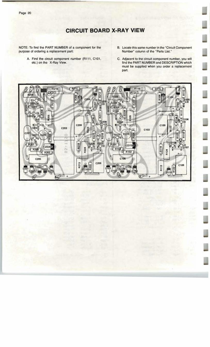
CIRCUIT BOARD X-RAY VIEW
NOTE: To find the PART NUMBER of a component for the purpose of ordering a replacement part :
A. Find the circuit component number (R111, C101, etc.) on the X-Ray View.
B. Locate this same number in the "Circuit Component Number" column of the "Parts List. "
C. Adjacent to the circuit component number, you will find the PART NUMBER and DESCRIPTION which must be supplied when you order a replacement part.
~ o
o~,..".. i--:
:;;a: :~ -~ ~; :!:"" ., u 1: ....
- =
I '.,~~ ~~ n ~ ~
I -7
~,~ ~ ~ .'" ~
[--,,,,,,,,,,,,,,,
;
i I I L.t
1'1 I !: !,: , l,,,,, :- !:J.. .. -~ -- ,

--
"'L.OT
A.:I~ -Cun.,-tII'l"' ,Io.' 11'(.
j.'Joit fMppty -3oIado.acaIt-l:",mlI"Il("" IJl j RH'IC<lI{· _ O(,;·J·....
,. 1
'")j r ,\
~. ~(J.' ~~ r- . ~\
>~'. = ,~, I) • I L .,'a ~
c, ~ II ,~ . './' 1I"...1oB~lIf;:"I'i lrvt"'l,.ll''\r"....on;;a'"ll''l~ , jl".FI.'''-'D
r
· ~ \' . ~- II Ilj"' " ' . MOOE-S'MT~. a Wl ' ~ ... tuPd>'r ", 19N*
.., - - - + + L2"""'",-._ _ ____...-J
~ . ._ 76-= .~_r~ ~i!~=~~g ~=~, ,JI
METER; . ~
,
~V~SL.iWW.
fir,.w;l:Io(atoI-O(' Jt'l""9'"
I POVIf.A swrrCH, SW1:
.,;.,rc:A :II po;orr.-~ ~4QY:IIIs~.,..,!t7\"
'''' '-'' ,,., ~fr ... , .......
UI'lE SNITCH. SW2 (UNOERSIOE Of' C",.SS&8~; s.a.c.r.nrrllCl~.I"".,~!Ooe WXlMOloDl'llnllr)
Cf.,lJT\O,"I Oo.tau,"f\ 01"1 ... II1··~ _~ ..,.,,.,,,,,
--------- -.-OlJT1I\I T"A'~S.JI_I'-l 'lItCl.r~;JttaJlh.. "",-, -ru.'tO/l' ,.~kI/I(:_.'Id"""*1\J:~S4oOfl~ ,.. .y0ll
lnIt.~or!~cgrroiI'4'1TIW~porMN"'or ,.4IgfitV'~~ "".,...~T.trl...,<nIlCI!'Cf(f.J'( o..~1r !bIC- .. ~f't«!r3*~~"" .;1_
~
Figure 1