Embed Size (px)
Citation preview

1
Heat Transfer Efficiency and Capital Cost Evaluation of a Three-Phase Direct
Contact Heat Exchanger for the Utilisation of Low-Grade Energy Sources
Hameed B. Mahood *1, 2, Alasdair N. Campbell1, Rex B. Thorpe1, and Adel O. Sharif 1,3
1Centre for Osmosis Research and Applications (CORA), Department Chemical and Process
Engineering, Faculty of Engineering and Physical Sciences, University of Surrey, Guildford GU2
7XH, UK
*e-mail: [email protected]
2University of Misan, Misan, Iraq, e-mail: [email protected]
3The Qatar Foundation, Qatar Energy and Environment Research Institute, Qatar
Abstract
Low-grade energy cycles for power generation require efficient heat transfer equipment.
Using a three-phase direct contact heat exchanger instead of a surface type exchanger, such
as a shell and tube heat exchanger, potentially makes the process more efficient and
economic. This is because of its ability to work with a very low temperature driving force, as
well as its low cost of construction. In this study, an experimental investigation of the heat
transfer efficiency, and hence cost, of a three-phase direct contact condenser has been carried
out utilising a short Perspex tube of 70 cm total height and 4 cm internal diameter. Only 48
cm was used for the direct contact condensation. Pentane vapour with three different initial
temperatures (40℃, 43.5℃ and 47.5℃) was contacted with water with an inlet temperature
of 19℃. In line with previous studies, the ratio of the fluid flow rates was shown to have a
controlling effect on the exchanger. Specifically, the heat transfer efficiency increased
virtually linearly with this ratio, with higher efficiencies also being observed with higher flow

2
rates of the continuous phase. The effect of the initial temperature of the dispersed phase was
shown to have a lower order impact than flow rate ratio. The capital cost of the direct contact
condenser was estimated and it was found to be less than the corresponding surface
condenser (shell and tube condenser) by 30 times. An optimum value of the continuous phase
flow rate was observed at which the cost of the condenser is at a minimum.
Keywords: Three-phase direct contact condenser, heat transfer efficiency, costing
1. Introduction
Energy usage is increasing around the world due to the development of technologies and
population growth. Recent research revealed that the demand for energy could rise by up to
1.7% annually until 2030 [1]. However, fossil fuels remain the dominant energy source,
producing about 80% of the gross energy required, while renewable energy contributes only
11%. Accordingly, many environmental problems such as global warming, ozone depletion
and air pollution will increase. Furthermore, the fossil fuel prices will likely rise. Hence,
industrial waste energy, especially from low-grade heat sources, for power production has
recently received more attention [1]. This can be efficiently achieved by using a direct
contact concept.
Most popular heat exchangers that are used in practice are surface type heat exchangers, in
which hot and cold fluids are separated completely by metallic barriers. Shell-and-tube heat
exchangers are a classic example of this type of exchanger. This, of course, results in a
reduction in the rate of heat exchange between fluids and consequently reduces the process’s
efficiency, and increases the capital and operational costs. As a result, the implementation of
such heat exchangers in heat recovery processes, or in low-grade thermal energy cycles for
power generation (e.g. in solar energy systems such as solar ponds and solar collectors), is
inefficient.

3
Thus, attempts to enhance the efficiency of conventional heat exchangers have recently
received more attention. For example, Dizaji et al. [2] have demonstrated experimentally that
the effectiveness of a shell-coiled type heat exchanger is significantly improved by the
injection of small air bubbles into the exchanger shell. In the same context, Rashidi et al. [3]
studied theoretically the effect of using a porous material inside a conventional heat
exchanger on its performance. Their exchanger was used for a solar energy application. They
concluded that using a porous substrate with a high Darcy number can improve the thermal
performance of the heat exchanger with an acceptable increase in pumping cost.
Alternatively, a direct contact heat exchanger allows working fluids to come into direct
physical contact by eliminating the solid barriers. A high heat transfer rate, an absence of
corrosion and fouling problems, a lower cost, a simple design and the potential to work at a
very low temperature driving force are the main advantages of using direct contact heat
exchangers. Accordingly, they can be found in many applications, for example water
desalination, geothermal power generation, solar energy [4-6] and in low cost hydrogen
generation from a direct mixing of water or gaseous hydrocarbons gas with Pb or Pb-Bi
heavy liquid metal [7] . The three-phase direct contact heat exchanger (used as an evaporator
or condenser) generally operates by injection of drops or bubbles as a dispersed phase into a
flowing column of another immiscible liquid, which acts as a continuous phase. The
temperature of the continuous phase must be above the boiling point of the drops for
evaporation, or less than the saturation temperature of the bubbles in the case of
condensation. An intimate mixing of the dispersed phase and the continuous phase can be
achieved. The drops or bubbles therefore evaporate or condense directly when they touch the
continuous phase, and two-phase bubbles are formed.
The main limitation of the direct contact heat exchanger is that a mutual mixing of fluids
occurs due to their intimate direct contact. This necessitates an additional cost for separation.

4
Practically, this problem can be all but eliminated by using two immiscible fluids, separation
of which can be achieved using gravity. A second, more problematic, limitation is the
difficulty in accurately predicting the direct contact heat exchanger’s performance. Due to the
mixing of the two fluids, a high, but difficult to predict, interfacial area for heat exchange is
created, especially when the process involves bubbles or drops [8]. The difficulty in
modelling the extent of this interfacial area means there is a general dearth of specialised
mathematical theory and, indeed, experimental measurements or correlations, which can be
used for design proposes. This is especially true for condensers. Furthermore, a detailed
understanding of the hydrodynamic phenomena is also required if a functional, plant-scale
exchanger is to be designed. Such direct contact devices can, potentially, suffer from
problems due to flooding and back mixing. Such problems can only be understood, and
ultimately overcome, through detailed experimental and theoretical study.
In spite of the great potential of the direct contact heat exchanger for use in fields such as
energy recovery and renewable energy it is, somewhat surprisingly [8, 9], not widely
mentioned in the heat transfer handbooks. Much attention has focussed on the simpler
problem of the heat transfer and the hydrodynamics in the direct contact condensation of
single bubbles [5, 6, 10-18] and trains of multiple bubbles [20-22]. Only Sideman and
Moalem [23] studied, theoretically, the parameters that control the performance of a direct
contact three-phase condenser. They exploited previous models of the condensation of a
single two-phase bubble in an immiscible liquid. Recently, Mahood et al. investigated the
three-phase direct contact condenser theoretically [21] and experimentally [24-29]. These
studies investigated various characteristics of the thermal performance of a lab.-scale direct
contact condenser during both transient and steady state operation. Specifically, the overall
volumetric heat transfer coefficient during transient operation [24] was measured. A model
was proposed for the steady state temperature distribution, which compared favourably with

5
the experimental measurements [25]. Furthermore, a model predicting the transient
temperature profile along the length of the direct contact column was also developed [26].
The effects of various parameters, such as the ratio of the mass flow rates of the continuous
and dispersed phases, on the outlet temperatures was also investigated [27]. In addition, the
variation of the volumetric heat transfer along the column [28], and the suitability of direct
contact condensation for use in desalination were also investigated [29].
These studies produced promising results, which showed the effect of key process parameters
on the thermal outputs of the condenser. The specifics of these thermal effects must,
however, be considered in totality by investigating the condenser’s efficiency and capital
cost; it is these parameters that will ultimately determine the industrial relevance of this
technology. These two critical measures of exchanger performance have not been
investigated previously. Therefore, this work reports these important properties of the three-
phase direct contact condenser for the first time.
Specifically, an experimental investigation of the heat transfer efficiency in a three-phase
direct contact is described in section 2. The effects of the operational parameters, such as the
dispersed phase mass flow rate, the continuous phase mass flow rate and the initial dispersed
phase temperature on the heat transfer efficiency are examined in section 3. Subsequently,
these results are used to estimate the capital cost of the direct contact condenser, which is
then compared to the cost of a traditional shell and tube condenser.
2. Experimental setup and procedure
A general view and a schematic layout of the experimental test rig are shown in Fig. 1(a).
The test section is a Perspex cylindrical column with a total height of 70 cm and 4 cm internal
diameter. The volume is thus 0.00352 m3. Only 48 cm (0.00241 m3) was used as the active
height (i.e. the height containing the continuous phase) during the experiments. The pentane,

6
in the vapour phase, was introduced into the bottom of the column via a tube of 6mm internal
diameter. Similarly, the continuous phase was removed from the bottom of the column via a
tube with 6 mm internal diameter. At the top of the column, a 6 mm tube introduced the
continuous phase, and a 6 mm tube, well above the initial water level, was used to remove the
condensed pentane. In addition, five equally spaced (12 cm spacing) holes along the height of
the column were used to insert thermocouples into the column to measure the temperature of
the continuous phase and the condensed material.
The heating vessel is a rectangular stainless steel vessel, of dimensions 50 cm × 40 cm ×
50 cm (0.1 m3 volume). Two electrical heaters are fixed near to its base; each one has a
power of 3kW, and is connected to a thermostatic controller. The vessel contains a long
copper coil (6.5 m long with 6 mm diameter) which can be completely immersed in water,
which is used as a heating medium. The temperature of this water was measured by a digital
thermometer. This coil was used to carry and vaporise the dispersed phase pentane. At the
base of the vessel, the coil connects to the liquid pentane storage tank, whilst at the top of the
vessel the coil joins with the condenser’s test section via an externally heated short tube and
sparger. The sparger is a conical shape, formed from Perspex with a circular plate attached to
its top. The total diameter of the sparger at the injection point is 34 mm and the sparger plate
diameter is 26 mm. The total height of the sparger is 42 mm. The plate contains 48 orifices
each of 0.5 mm diameter, and is fixed to the body of the sparger by 8 screws. The orifice
plate has a thickness of 3 mm. Eight radially aligned rows of 4 orifices appear in the pattern
shown in Fig. 1 (b). Additionally, two holes were added circumferentially in between the
rows.
The water supply system provides the continuous phase in the condenser. The water storage
tank is a large plastic rectangular shape tank with a volume of 160 L. A low flow rate
centrifugal pump (4 kg/min maximum mass flow rate) feeds the continuous phase from the

7
storage tank to the top of the condenser via a rotameter. The water flow was controlled
manually by a recirculation loop.
The liquid pentane storage tank is a 10 L plastic tank connected to the liquid pentane feed
pump via a short plastic tube. The pump is a centrifugal low flow rate pump (4 kg/min
maximum) which supplies pentane to the heating vessel. A recirculation loop controlled the
mass flow rate of liquid pentane. A pressure gauge (1 barg maximum) measured the liquid
pentane feed pressure, before it entered the heating vessel. In addition, the temperature and
pressure of the vapour pentane were measured before injection into the test section of the
condenser. This technique is described in more detail elsewhere [30] and was used in
previous studies [24-28]. The pentane was injected at a pressure of 0.2 barg. A large
temperature range trace heater (total power 10 W m2⁄ and a maximum working temperature
of 200℃) with controller maintained a constant vapour temperature in the line prior to
injection. The vapour temperature was measured just before injection into the test section by
a thermocouple. Calibrated K-Type thermocouples measured (i) the temperature of the
continuous phase along the test section, (ii) the dispersed phase vapour, (iii) the condensate
and (iv) the continuous phase inlet and outlet. All these thermocouples connect to an eight
channel data logger and PC.
Normal Pentane (C5H12) (Fisher Scientific, 99+ % purity) was used as the dispersed phase;
its general and physical properties are given in Table 1. Tap water was used as the continuous
phase. The experiments began with the preparation of the continuous phase by heating the
water to 19℃. The large storage tank size and short duration (2-3 minutes) of each individual
experimental run helped to maintain the continuous phase temperature at this value. The inlet
and outlet rotameters were set such that the flow rates of water into and out of the column
were identical. Concomitantly, the heating vessel was warmed by gradually increasing the
electrical power to the heaters until the desired temperature for the particular experiment was

8
reached. The liquid pentane was then vaporised in the coil, and injected into the direct contact
test section via the trace-heated pipe. The injection pressure and the vapour temperature were
measured using a pressure gauge and a thermocouple. At the point of vapour injection, the
temperature distribution along the direct contact test section (condenser) was measured and
read by the PC. The condensate formed (as a separated layer at the top of the column) well
above the water inlet, and after each run it was collected and sent back to the liquid pentane
storage tank, or stored and used in another run. The condenser was run for around 3 minutes
until a steady state was reached in the column. A separating conical flask was used for
separating the condensed pentane from any entrained water. The dispersed phase mass flow
rate was calculated using a mass balance for each individual run i.e. the collected pentane
was weighed and divided by the run duration. The initial conditions of the experiments
appear in Table 2. The uncertainty in the thermocouples appears in Tables 3. The uncertainty
of the continuous flow measurement depends on flow rate range. It was ±6.0% for flow rates
from 0 to 0.1kg min⁄ , ±9.7% for flows from 0.1kg min⁄ to 0.3kg min⁄ and finally ±4.7% for
continuous phase flow rates greater than 0.3kg min⁄ . For the dispersed phase mass flow rate
measurement, the mass balance after each run was used. The total error in the measurements,
which consisted of the error in the digital scale, the loss of condensate due to the miscibility
of pentane in water (which is very small), the time of the run and the possibility of draining
the condensate with the continuous phase was calculated. The inaccuracy of the dispersed
phase mass flow rate is estimated at ±11%.
Table 1 The physical properties of n-pentane at 1 bar and saturation temperature
Property Values
Saturation temperature (°𝑪) 36.0
Molar mass (𝒌𝒈 𝒌𝒎𝒐𝒍⁄ ) 72.15
Thermal diffusivity (𝒎𝟐 𝒔⁄ ) 7.953× 10⁻⁸

9
Specific heat of liquid (𝒌𝑱 𝒌𝒈 𝑲⁄ ) 2.363
Specific heat of vapour (𝒌𝑱 𝒌𝒈 𝑲⁄ ) 1.66
Thermal conductivity of liquid 𝑾 𝒎 𝑲⁄ 0.1136
Thermal conductivity of vapour(𝑾 𝒎 𝑲⁄ ) 0.015
Kinematic viscosity (𝒎𝟐 𝒔⁄ ) 2.87× 10⁻⁷
Viscosity (𝒌𝒈 𝒎 𝒔⁄ ) 1.735× 10⁻⁴
Latent heat of vaporisation (𝒌𝑱 𝒌𝒈⁄ ) 359.1
Density of liquid (𝒌𝒈 𝒎𝟑⁄ ) 621
Density of vapour (𝒌𝒈 𝒎𝟑⁄ ) 2.89
Surface tension (𝑵 𝒎⁄ ) 0.01432
Table 2 The initial conditions of the experiments.
𝑇𝑣𝑖(℃) 𝑇𝑐𝑖(℃) 𝐻𝑜(𝑚) ��𝑐 (𝑘𝑔
𝑚𝑖𝑛) 𝑅 =
��𝑣
��𝑐
× 100%
40 19 0.48
0.0564 16.134 31.028 49.64 58.51 66.595
0.107 11.186 13.983 18.178 22.373 32.628
0.2015 7.318 9.922 13.693 14.883 19.051
0.286 5.3497 7.447 8.95 10.56 14.335
0.38 4.8 6.037 7.427 8.46 9.366
43.5 19 0.4
0.0564 15.319 11.49 8.13 4.825 3.935
0.107 29.078 17.34 9.37 7.52 4.5
0.2015 37.234 25.58 11.41 8.82 5.07
0.286 41.666 26.7 14.25 10.489 6.776
0.38 52.766 29.94 18.6 13.986 8.366
47.5 19 0.48
0.0564 3.89 5.674 7.674 11.281 13.222
0.107 4.73 8.664 9.535 11.643 12.587
0.2015 7.918 10.567 15.628 17.711 19.3
0.286 11.606 16.92 22.876 26.708 28.582
0.38 25.37 30.32 35.561 45.266 54.415

10
Table 3 Inaccuracy of the thermocouples
T(℃) Inaccuracy %
𝑻𝑐𝟏 ±0.440
𝑻𝑐𝟐 ±0.508
𝑻𝑐𝟑 ±0.325
𝑻𝑐𝟒 ±0.359
𝑻𝒄𝒐𝒏𝒅 ±0.582
𝑻𝒅𝒊 ±0.480
𝑻𝒄𝒊 ±0.353
1

11
2
3
4
5
6
7
8
9
10
11
1
Water tank
Pump
Rotameter
Recycle
Trace heater controller Pump
Recycle
Tes
t se
ctio
n
(DC
C)
Thermocouples
Rotamete
Water out to
drain
Water inlet
Condensate
Two-phase bubbles Data logger
PC
Separator
Water out
Condensate
Collecting vessel
Electrical heaters (2) Heating vessel
Helical coil
Heater Controller
Sparger Vapour
pentane inlet
tube Pressure gauge
Water
Condensate
Pentane tank
Non-return valve Liquid pentane
Fig. 1 a. Schematic diagram of the experimental rig.
Valve

12
2
3
4
Fig. 1 b. Orifice plate configuration of the sparger.
207
3. Results and discussion 208
3.1 Heat Transfer Efficiency 209
The direct contact heat exchanger can save money, energy, and space because of its ability to 210
transfer heat between contacting fluids efficiently, due to the absence of heat transfer 211
surfaces. The efficient implementation of the three-phase direct contact condenser requires a 212
good knowledge of the impact of different operational parameters on the exchanger 213
performance. 214
Essentially, the direct contact condensation process is accomplished by mixing of the vapour 215
with a subcooled liquid. A simple heat balance can be used to determine the amount of vapour 216
condensed by a specific amount of liquid. Theoretically, the cooling fluid can be heated to any 217
Screw hole Orifice hole
26 mm
34 mm

13
desired temperature by controlling the pressure of the vapour and the liquid flow rates. The 218
following expression is used to calculate the three-phase direct contact efficiency: 219
𝑒𝑓𝑓𝑖𝑐𝑖𝑒𝑛𝑐𝑦 % =𝑇𝑐𝑜−𝑇𝑐𝑖
𝑇𝑑,𝑠𝑎𝑡−𝑇𝑐𝑖× 100% (1) 220
where 𝑇𝑐𝑜, 𝑇𝑐𝑖 and 𝑇𝑑,𝑠𝑎𝑡 represent the continuous phase outlet temperature, the continuous 221
phase inlet temperature and the vapour saturation temperature, respectively. This, of course, 222
assumes that no heat is lost to the surroundings. Given the short duration of the experiments, 223
and the small temperature difference across the insulating Perspex wall of the column, this 224
assumption is entirely reasonable in the current context. 225
The mass flow rate ratio has been shown to be an effective operational parameter for 226
controlling the heat transfer characteristics of the three-phase direct contact condenser [25, 227
26]. The effect of the mass flow rate ratio, for three different initial dispersed phase 228
temperatures, on the efficiency of the direct contact condenser is shown in Figs. 2-4. The 229
mass flow rate ratio was altered by varying the dispersed phase mass flow rate with a constant 230
continuous mass flow rate. As shown in Figs. 2-4 , the efficiency of the direct contact 231
condenser increases with increasing mass flow rate ratio. For example, in Fig. 2, for an initial 232
dispersed phase temperature of 40 °C it is clear that for each discrete value of continuous 233
phase flow rate the efficiency increases almost linearly with mass flow rate ratio. It is also 234
evident that the rate at which the efficiency increases with increased mass flow rate ratio 235
depends on the continuous phase flow rate. Thus, at the highest continuous phase flow rate 236
(0.38 kg/min) the efficiency increases above 50% when the mass flow rate ratio is 237
approximately 59%. In contrast, at the lowest flow rate, the efficiency reaches this level when 238
R ~ 12%. Unsurprisingly, the system is much more sensitive to variation in R when the 239
continuous phase flow rate is low. This makes intuitive sense, as there is less cooling 240
available via the continuous phase. Similar trends are evident in Figs. 3 and 4 for different 241
initial temperatures of the dispersed phase. Comparison of all three plots also reveals that 242

14
there is a slight increase in efficiency when a higher initial temperature is used. This effect is, 243
however, clearly second order when compared to the effect of mass flow rate ratio. As 244
discussed above, the key factor determining the efficiency is the energy gained by the cold 245
fluid (Tco − Tci) with increasing mass flow rate ratio, which was noted and discussed by 246
Mahood et al. [25]. Physically, the increase of the mass flow rate ratio means that more 247
heating medium is supplied to the condenser, which results in an enhancement of the heat 248
transfer process, and consequently an increase in the efficiency of the three-phase direct 249
contact condenser. Interestingly, and depending somewhat on the continuous phase mass 250
flow, the dispersed phase mass flow rate required to approach a relatively high efficiency 251
seems low. This is, of course, impacts the operational cost of the three-phase direct condenser, 252
because the process will be carried out using a relatively small quantity of working fluid. 253
The results presented above would suggest that the maximum efficiency can be achieved by 254
using a low continuous phase mass flow rate and a high mass flow rate ratio; however, 255
flooding is still the main shortcoming associated with the three-phase direct contact 256
condenser. The probability of flooding actually increases with increasing dispersed phase 257
mass flow rate, or decreasing continuous mass flow rate, i.e. when the mass flow ratio is 258
large. This clearly places an operational limit on the mass flow ratio that can be practically 259
employed, which compromises the efficiency somewhat. As with many engineering systems, 260
a compromise between these competing effects must be sought. To reduce or avoid the 261
negative effects of flooding, operation with a relatively high continuous phase mass flow rate 262
is required. Figs. 2-4 clearly show that operating in this manner leads to a reduction in the 263
efficiency of the condenser, but this can be offset by manipulation of the flow ratio and initial 264
temperature of the dispersed phase. The three-phase direct contact condenser therefore can be 265
operated more efficiently than the corresponding shell and tube condenser. As shown in Figs. 266
2-4 and for a constant mass flow rate ratio, a higher continuous phase mass flow rate results in 267

15
higher direct contact condenser efficiency. This could be due to an efficient condensation 268
process taking place when sufficient cooling water is available; otherwise, a fraction of 269
vapour is still not completely condensed. In the present study, these effects clearly appear at 270
low continuous mass flow rates (0.06 to 0.11 kg/min). They gradually decrease with 271
increasing continuous phase mass flow rate (0.11 - 0.20 kg/min) and nearly disappear at high 272
continuous mass flow rates (0.20 - 0.38 kg/min). Practically, for a given dispersed phase mass 273
flow rate, there is a continuous phase mass flow rate that is required to achieve a complete 274
direct contact condensation process. The additional coolant in the condenser results in a 275
reduction in the continuous phase outlet temperature, and subsequently, a reduction in the 276
efficiency of the three-phase direct contact condenser. 277
Figure 5 shows the variation of the three-phase direct contact condenser efficiency with the 278
temperature difference between the two-phases at their inlet conditions, for three different 279
continuous mass flow rates. A slight increase of the condenser efficiency with increasing 280
initial temperature difference between the contacting fluids is shown. A higher initial 281
temperature difference between the contacting fluids results in a higher convective heat 282
exchange, and increases the energy absorbed by the continuous phase. Again, it is quite clear 283
that at a given temperature difference, the efficiency of the direct contact condenser is higher 284
when the continuous mass flow rate is high. The error in the efficiency, which appears as 285
error bars in the Fig. (2-4) was estimated using a similar method to that outlined elsewhere 286
[31]. 287

16
288
Fig. 2. Direct contact heat exchanger efficiency versus mass flow rate ratio for an initial 289
dispersed phase temperature of 40 °C and five continuous phase flow rates 290
291
292
Fig. 3. Direct contact heat exchanger efficiency versus mass flow rate ratio for a dispersed 293
phase initial temperature of 43.5 °C and five continuous phase flow rates 294
295
0
10
20
30
40
50
60
70
0 10 20 30 40 50 60 70
Effi
cie
ncy
%
Mass Flow Rate Ratio (R%)
mc(kg/min)=0.0564 0.107 0.201 0.286 0.381
0
10
20
30
40
50
60
70
80
0 10 20 30 40 50 60
Effi
cie
ncy
%
Mass Flow Rate Ratio (R%)
mc(kg/min)=0.0564 0.107 0.201 0.286 0.381

17
296
Fig. 4. Direct contact heat exchanger efficiency versus mass flow rate ratio for a dispersed 297
phase initial temperature of 47.5 °C and five continuous phase flow rates 298
299
300
301
Fig. 5. Direct contact heat exchanger efficiency versus temperature difference between the 302
two-phases at (Tdi − Tci) for three different continuous mass flow rates 303
304
305
306
0
10
20
30
40
50
60
70
80
0 10 20 30 40 50 60 70
Effi
cie
ncy
%
Mass Flow Rate Ratio (R%)
mc(kg/min)=0.0564 0.107 0.201 0.286 0.381
0
10
20
30
40
50
60
70
19 21 23 25 27 29
Effi
cie
ncy
%
ΔT (oC)
mc(kg/min)=0.0564 0.107 0.201
18
3.2 Direct contact condenser costing 307
Beside the limitations of thermal energy extraction, the costs, both initial and operational, are 308
another problem encountered in the selection and use of the surface type heat exchanger. The 309
high initial cost results from the large surface area required to overcome the low heat transfer 310
rate, while the operational cost is mainly due to the expenses from the continuous 311
maintenance due to fouling and corrosion. Although such problems can be alleviated by 312
different technologies, an increase in capital and operational cost would result. For example, 313
implementation of special materials of construction, which are normally expensive, increases 314
the capital cost, and further treatment of feed water using e.g. corrosion inhibiters increases 315
the operational cost. Therefore, the direct contact heat exchanger may be used, potentially, in 316
fields when surface type heat exchangers are not economical. However, estimation of the 317
capital cost of a direct contact condenser and comparison with the cost of shell and tube type 318
of equivalent duty is very important to support this claim. 319
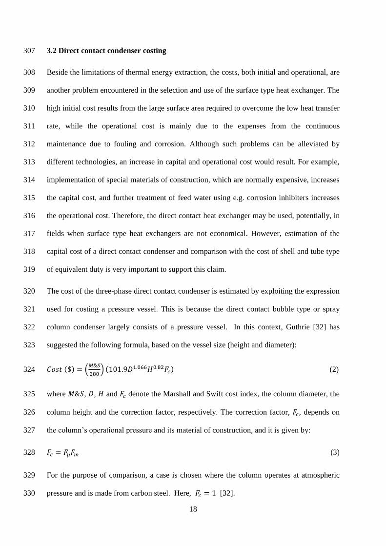
The cost of the three-phase direct contact condenser is estimated by exploiting the expression 320
used for costing a pressure vessel. This is because the direct contact bubble type or spray 321
column condenser largely consists of a pressure vessel. In this context, Guthrie [32] has 322
suggested the following formula, based on the vessel size (height and diameter): 323
𝐶𝑜𝑠𝑡 ($) = (𝑀&𝑆
280) (101.9𝐷1.066𝐻0.82𝐹𝑐) (2) 324
where 𝑀&𝑆, 𝐷, 𝐻 and 𝐹𝑐 denote the Marshall and Swift cost index, the column diameter, the 325
column height and the correction factor, respectively. The correction factor, 𝐹𝑐, depends on 326
the column’s operational pressure and its material of construction, and it is given by: 327
𝐹𝑐 = 𝐹𝑝𝐹𝑚 (3) 328
For the purpose of comparison, a case is chosen where the column operates at atmospheric 329
pressure and is made from carbon steel. Here, 𝐹𝑐 = 1 [32]. 330

19
The Six-Tenths Rule is used for pricing the shell and tube heat exchanger [33]. According to 331
this rule, the cost of new equipment can be estimated if the cost of similar equipment, but for 332
a different size, is available. The Six-Tenths Rule is given by: 333
𝐶𝐴 = 𝐶𝐵 (𝑆𝑖𝑧𝑒 𝐴
𝑆𝑖𝑧𝑒 𝐵)
0.6
(4) 334
where 𝐶𝐴 is the cost of new equipment (e.g. shell and tube heat exchanger) of size 𝐴, while 335
𝐶𝐵 represents the cost of equipment of another size, 𝐵. 336
To update the shell and tube heat exchanger cost, the following expression is used [34]: 337
𝐶𝐴−𝑛𝑒𝑤 = 𝐶𝐴−𝑜𝑙𝑑 (𝐼𝐴−𝑛𝑒𝑤
𝐼𝐴−𝑜𝑙𝑑) (5) 338
where I represents the cost index, in our case the Marshall and Swift index. 339
Thus, the cost of chemical engineering equipment, including heat exchangers is directly 340
proportional to its size (heat transfer area) raised to the power 0.6. The heat transfer area can 341
be calculated as: 342
𝐴 =𝑄
𝑈∆𝑇𝑙𝑚 (6) 343
where 𝑄, 𝑈 and ∆𝑇𝑙𝑚 represent the heat transfer rate, the heat transfer coefficient and the log 344
mean temperature difference, respectively. The log mean temperature difference may be 345
calculated from the experimentally measured temperatures. 346
Accordingly, the heat exchanger cost can be written as: 347
𝑐𝑜𝑠𝑡 = (𝑄
𝑈∆𝑇𝑙𝑚)
0.6
. 𝐾𝑐 (7) 348
The merit of the three-phase direct contact heat exchanger is its capability to offer a high heat 349
transfer coefficient and therefore, a low area and low cost. One way to compare the 350
performance of two different types of heat exchangers is to compare the heat transfer 351
20
coefficient (𝑈) values. However, 𝑈 is unbounded. The reciprocal of the heat transfer 352
coefficient (1 𝑈⁄ ) is another comparison, being the resistance to heat transfer, and for an 353
improved design this should lie between the existing design value and zero. This is also 354
convenient for graphical comparison. Hence, it is useful to rearrange Eq. (7) as: 355
𝐶𝑜𝑠𝑡1 0.6⁄ ∆𝑇𝑙𝑚
𝑄=
1
𝑈 (8) 356
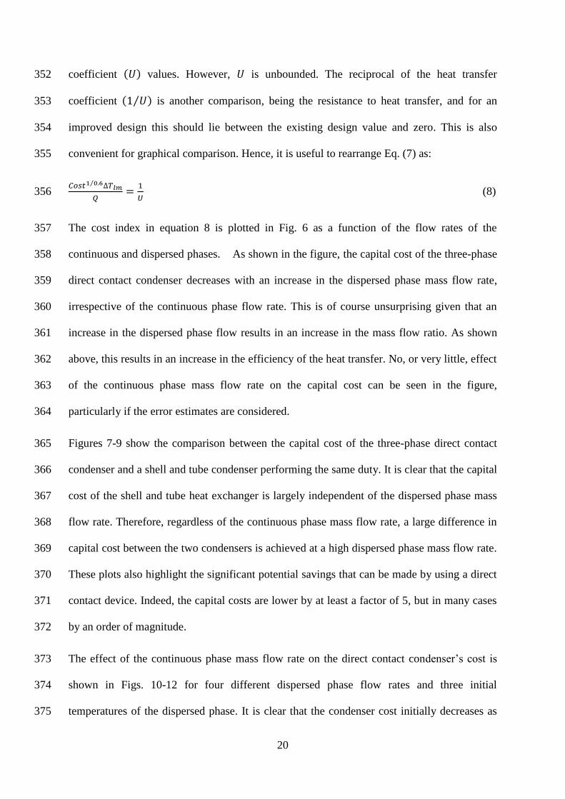
The cost index in equation 8 is plotted in Fig. 6 as a function of the flow rates of the 357
continuous and dispersed phases. As shown in the figure, the capital cost of the three-phase 358
direct contact condenser decreases with an increase in the dispersed phase mass flow rate, 359
irrespective of the continuous phase flow rate. This is of course unsurprising given that an 360
increase in the dispersed phase flow results in an increase in the mass flow ratio. As shown 361
above, this results in an increase in the efficiency of the heat transfer. No, or very little, effect 362
of the continuous phase mass flow rate on the capital cost can be seen in the figure, 363
particularly if the error estimates are considered. 364
Figures 7-9 show the comparison between the capital cost of the three-phase direct contact 365
condenser and a shell and tube condenser performing the same duty. It is clear that the capital 366
cost of the shell and tube heat exchanger is largely independent of the dispersed phase mass 367
flow rate. Therefore, regardless of the continuous phase mass flow rate, a large difference in 368
capital cost between the two condensers is achieved at a high dispersed phase mass flow rate. 369
These plots also highlight the significant potential savings that can be made by using a direct 370
contact device. Indeed, the capital costs are lower by at least a factor of 5, but in many cases 371
by an order of magnitude. 372
The effect of the continuous phase mass flow rate on the direct contact condenser’s cost is 373
shown in Figs. 10-12 for four different dispersed phase flow rates and three initial 374
temperatures of the dispersed phase. It is clear that the condenser cost initially decreases as 375

21
the continuous phase mass flow rate is increased. It reaches a minimum value, the magnitude 376
and location of which depends on the dispersed phase mass flow rate. Beyond the minimum 377
value, the cost increases once more as the continuous flow rate is increased. This optimum 378
value for the continuous phase clearly arises from the need to have sufficient continuous fluid 379
to fully condense the dispersed phase, without having too much, which would impair the 380
efficiency and therefore lead to an oversized exchanger. 381
382
Fig. 6. The variation of capital cost of the three-phase direct contact condenser with the 383
dispersed phase mass flow rate for a constant dispersed phase initial temperature (Tdi =384
40℃) and five different continuous phase mass flow rates. 385
386
387
388
389
0
100
200
300
400
500
600
700
800
900
0 0.01 0.02 0.03 0.04 0.05
Co
st1
/0.6
. ∆Tl
m/Q
($
1/0
.6.o
C/W
)
Dispersed Phase Mass Flow Rate (kg/min)
mc(kg/min)=0.0564 0.107 0.201 0.286 0.381

22
390
Fig. 7. Comparison between the three-phase direct contact condenser’s capital cost and shell 391
and tube condenser cost for five different continuous phase mass flow rates and dispersed 392
phase initial temperatures (Tdi = 40℃). 393
394
395
Fig. 8. Comparison between the three-phase direct contact condenser’s capital cost and shell 396
and tube condenser cost for five different continuous phase mass flow rates and dispersed 397
phase initial temperatures (Tdi = 43.5℃). 398
399
400
401
402
0
1000
2000
3000
4000
5000
0 0.01 0.02 0.03 0.04 0.05
Co
st1/
0.6. Δ
TLM
/Q (
$1/
0.6
.oC
/W)
Dispersed Phase Mass Flow Rate (kg/min)
mc(kg/min)=0.0564 0.107 0.201
0.286 0.381 Shell and Tube
0
1000
2000
3000
4000
5000
0 0.01 0.02 0.03 0.04
(Co
st1
/0.6
. ΔTl
m/Q
) ($
1/0
.6.o
C/W
)
Dispersed Phase Mass Flow Rate (kg/min)
mc(kg/min)=0.0564 0.107 0.2010.286 0.381 Shell and Tube

23
403
404
Fig. 9. Comparison between the three-phase direct contact condenser’s capital cost and shell 405
and tube condenser cost for five different continuous phase mass flow rates and dispersed 406
phase initial temperatures (Tdi = 47.5℃). 407
408
409
410
Fig. 10. Capital cost of three-phase direct contact condenser versus continuous mass flow rate 411
for Tdi = 40℃ and four different dispersed phase mass flow rates. 412
413
414
0
1000
2000
3000
4000
5000
0.005 0.015 0.025 0.035 0.045 0.055
(Co
st1/
0.6.Δ
Tlm
/Q)
($1/
0.6.o
C/W
)
Dispersed Phase Mass Flow Rate (kg/min)
mc(kg/min)=0.0564 0.107 0.2010.286 0.381 Shell and Tube
0
50
100
150
200
250
300
350
400
450
0 0.1 0.2 0.3 0.4
Co
st1
/0.6
. ΔT/
Q (
$1
/0.6
. oC
/W)
Continuous Phase Mass Flow Rate (kg/min)
md(kg/min)=0.02 0.025 0.03 0.035

24
415
Fig. 11. Capital cost of three-phase direct contact condenser versus continuous mass flow rate 416
for Tdi = 43.5℃ and four different dispersed phase mass flow rates. 417
418
419
420
Fig. 12. Capital cost of three-phase direct contact condenser versus continuous mass flow rate 421
for Tdi = 47.5℃ and four different dispersed phase mass flow rates. 422
423
424
425
426
427
0
50
100
150
200
250
300
350
400
450
0 0.1 0.2 0.3 0.4
Co
st1/
0.6.Δ
T/Q
($
1/0.
6.
oC
/W)
Continuous Phase Mass Flow Rate (kg/min)
md(kg/min)=0.02 0.025 0.03 0.035
0
100
200
300
400
500
0 0.1 0.2 0.3 0.4
Co
st1
/0.6
. ΔT/
Q (
$1
/0.6
. oC
/W)
Continuous Phase Mass Flow Rate (kg/min)
md(kg/min)=0.02 0.025 0.03 0.035

25
To further show the economic advantages of the three-phase direct contact condenser, the 428
ratio of the surface type (shell and tube condenser) to the three-phase direct contact condenser 429
cost is calculated and shown in Fig. 13. It was found that this ratio increased with increasing 430
dispersed phase mass flow rate. No significant impact of the continuous phase mass flow rate 431
on the cost ratio can be identified from the figure. Only at very low continuous mass flow 432
rates (��𝑐 = 0.06 kg min⁄ ) does the ratio seem a bit lower than at the other continuous phase 433
mass flow rates, for an initial dispersed phase temperature 40℃. What is, once again, 434
highlighted by this figure is that the very efficient heat transfer that is achieved in a direct 435
contact condenser renders such a device considerably cheaper than the conventional 436
equivalent. Fig 13 shows that there can be a difference of over an order of magnitude 437
between the respective costs. 438
The effect of the initial temperature of the dispersed phase on the cost ratio is also evident 439
from Fig. 13. Obviously, the effect of the initial dispersed phase temperature becomes more 440
significant when the dispersed phase mass flow rate is higher. The initial temperature of the 441
dispersed phase seems to have little effect at low to moderate dispersed phase mass flow rates 442
(��𝑑 ≤ 0.025 kg/min). It impact is more significant at a high dispersed phase mass flow 443
rates (��𝑑 > 0.025 kg/min ). In such cases, the higher the initial dispersed phase 444
temperature, the higher the cost ratio. Nevertheless, this increase in the cost ratio, in total, 445
seems confined to the effect of the dispersed phase mass flow rate. 446
447

26
448
Fig. 13. Cost ratio versus dispersed mass flow rate for three different dispersed phase initial 449
temperatures (Tdi = 40℃, 43.5℃ and 47.5℃) and five different continuous phase mass 450
flow rates (mc = 0.0564, 0.107, 0.201, 0.286 and 0.381 kg min⁄ ) for each Tdi. 451
452
453
The total heat transfer and the log-mean temperature difference are the parameters that can 454
most affect the capital cost estimate of the direct contact condenser. The calculation of these 455
parameters is strongly dependent on the different operational parameters of the condenser, 456
such as the continuous phase mass flow rate and the initial dispersed phase temperature. 457
Although an increase of the continuous phase mass flow rate results in an enhancement of the 458
direct contact condensation in the condenser, the increase in the total heat transfer is still 459
limited and constrained by the dispersed phase mass flow rate. At the same time, such a rise 460
in the total heat transfer might be balanced by an increase in the log-mean temperature 461
difference, which results from a high cooling rate. The results indicated (see sections above) 462
that there is no substantial effect of the initial temperature of the dispersed phase on the heat 463
transfer in the three-phase direct contact condenser, and consequently that latent heat is 464
dominant in such a process. As a result, the effect of these parameters on the capital cost 465
estimate of the direct contact condenser is less significant. This can be clearly demonstrated 466
0
5
10
15
20
25
30
35
40
0 0.01 0.02 0.03 0.04 0.05
Co
st R
atio
(-)
Dispersed Phase Mass Flow Rate (kg/min)
Tdi(oC)=40 43.5 47.5
27
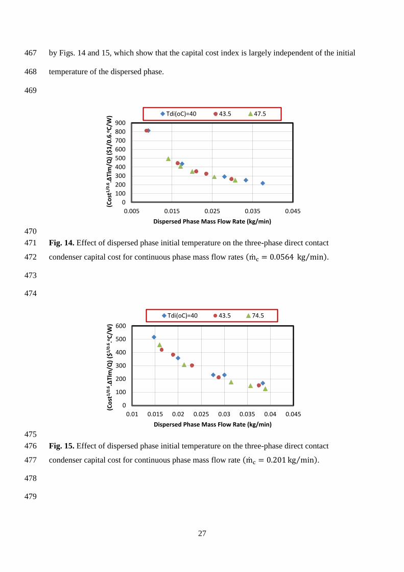
by Figs. 14 and 15, which show that the capital cost index is largely independent of the initial 467
temperature of the dispersed phase. 468
469
470
Fig. 14. Effect of dispersed phase initial temperature on the three-phase direct contact 471
condenser capital cost for continuous phase mass flow rates (mc = 0.0564 kg min⁄ ). 472
473
474
475
Fig. 15. Effect of dispersed phase initial temperature on the three-phase direct contact 476
condenser capital cost for continuous phase mass flow rate (mc = 0.201 kg min⁄ ). 477
478
479
0
100
200
300
400
500
600
700
800
900
0.005 0.015 0.025 0.035 0.045
(Co
st1/
0.6.Δ
Tlm
/Q)
($1
/0.6
.oC
/W)
Dispersed Phase Mass Flow Rate (kg/min)
Tdi(oC)=40 43.5 47.5
0
100
200
300
400
500
600
0.01 0.015 0.02 0.025 0.03 0.035 0.04 0.045
(Co
st1/
0.6.Δ
Tlm
/Q)
($1/
0.6.o
C/W
)
Dispersed Phase Mass Flow Rate (kg/min)
Tdi(oC)=40 43.5 74.5

28
4. Conclusions 480
The efficiency and the capital cost of the three-phase direct contact condenser have been 481
investigated experimentally. According to the experimental results, it is possible to conclude 482
that the condenser’s efficiency is significantly affected by the dispersed phase mass flow rate, 483
less so by the continuous phase mass flow rate and only slightly affected by the dispersed 484
phase initial temperature. Also, it was found that the condenser’s capital cost is mainly 485
affected by the dispersed phase mass flow rate. Very little effect of the continuous phase 486
mass flow rate is shown in the results. An optimal value of the continuous phase mass flow 487
rate at which the condenser’s capital cost was at a minimum was evident. No notable effect of 488
the dispersed phase initial temperature on the condenser’s capital cost was observed. 489
Finally, the insights gained about the direct contact condenser’s efficiency and capital cost 490
suggest that it is useful to operate at relatively high continuous phase mass flow rate and high 491
dispersed phase initial temperature. At these conditions, the efficiency of the condenser will 492
be high; its capital cost will be a minimum. Furthermore, the operation will be far from the 493
flooding limit of the column. 494
495
Nomenclture 496
A area (m2) 497
D diameter (m) 498
CA cost of equpment of size A ($) 499
CA cost of equpment of size B ($) 500
Fc total correction factor 501
Fm correction factor based on condenser operational pressure 502

29
Fp correction factor based on the condenser material 503
H total condenser height (m) 504
Ho active condenser height (water level) (m) 505
I cost index 506
Kc constant appearing in Eq. (7) 507
M&𝑆 Marshall and Swift cost index 508
mc continuous phase mass flow rate (kg min⁄ ) 509
md dispersed phase mass flow rate (kg min⁄ ) 510
R mass flow rate ratio 511
T temperature (℃) 512
∆Tlm log-mean temperature difference (℃) 513
U overall heat transfer coefficient (kJ m2s K⁄ ) 514
515
References 516
[1] Chen Y. Novel cycles using carbon dioxide as working fluid. Licenciate thesis, School of 517
Engineering and Management, Stockholm, 2006 518
[2] Dizaji H, S, Jafarmadar S, Abbasalizadeh M, Khorasani S. Experiments on air bubbles 519
injection into a vertical shell and coiled tube heat exchanger; exergy and NTU analysis. 520
Energy Conv Mang (2015); 103:973-980. 521
[3] Rashidi S, Bovand M, Esfahani J, A. Heat transfer enhancement and pressure drop 522
penalty in porous solar heat exchangers: A sensitivity analysis. Energy Conv Mang 523
(2015); 103:726-738. 524

30
[4] Dammel F, Beer H. Heat transfer from a continuous liquid to an evaporating drop: a 525
numerical analysis. Int J Therm Sci 2003; 4(7):677-686. 526
[5] Wanchoo R, Sharma S, Raina G. Drag coefficient and velocity of rise of a single 527
collasping two-phase bubble. AIChE J 1997;4(8):1955-1963. 528
[6] Wanchoo R. Forced convection heat transfer around large two-phase bubbles condensing 529
in an immiscible liquid. Heat Recovery Systems and CHP 1993; 13(5): 441-449. 530
[7] Gulevich A, Martynov P, Gulevsky V, Ulyanov V. Technologies for hydrogen 531
production based on direct contact of gaseous hydrocarbons and evaporated water with 532
molten Pb or Pb–Bi. Energy Conv Mang (2008); 49:1946-1950. 533
[8] Hewitt G, Shires G, Bott T. Process heat transfer, 1994, CRC Publication, New York. 534
[9] Vallario R, DeBellis D. State of technology of direct contact heat exchanging. 1984;84 535
NASA STI/Recon Technical Report N ,USA. 536
[10] Sideman S, Hirsch G. Direct contact heat transfer with change of phase: Condensation 537
of single vapor bubbles in an immiscible liquid medium. Preliminary studies, AIChE J 538
1965;11(6):1019-1025. 539
[11] Isenberg J, Sideman S. Direct contact heat transfer with change of phase: bubble 540
condensation in immiscible liquids. Int J Heat Mass Trans 1970;13(6):997-1011. 541
[12] Moalem D, Sideman S. The effect of motion on bubble collapse. Int J Heat Mass Trans 542
1973;16(12): 2321-2329. 543
[13] Higeta K, Mori Y, Komotori K. Condensation of a single vapor bubble rising in another 544
immiscible liquid. in AIChE Sym Ser1979; 75 (189), San Diego: 256-265. 545
[14] Higeta K, Mori Y, Komotori K. A novel direct-contact condensation pattern of vapour 546
bubbles in an immiscible liquid. The Canad J Chem Eng 1983; 61(6): 807-810. 547

31
[15] Lerner Y, Kalman H, Letan R. Condensation of an accelerating-decelerating bubble: 548
experimental and phenomenological analysis. J Heat Trans 1987;109(2): 509-517. 549
[16] Lerner Y, Letan R. Dynamics of condensing bubbles at intermediate frequencies of 550
injection. J Heat Trans 1990;112(3): 825-829. 551
[17] Kalman H, Mori Y. Experimental analysis of a single vapor bubble condensing in 552
subcooled liquid, Chem Eng J 2002;85(2): 197-206. 553
[18] Kalman H. Condensation of bubbles in miscible liquids. Int J Heat Mass Trans 2003; 554
46(18):3451-3463. 555
[19] Moalem D, Sideman S, Orell Hetsroni G. Direct contact heat transfer with change of 556
phase: condensation of a bubble train. Int J Heat Mass Trans 1973;16(12): 2305-2319. 557
[20] Kalman H. Condensation of a bubble train in immiscible liquids. Int J Heat Mass Trans 558
2006;49(13): 2391-2395. 559
[21] Mahood H B, Sharif A, Al-Ailbi S, Hossini A, Thorpe R B. Heat transfer modelling of 560
two-phase bubbles swarm condensing in three-phase direct-contact condenser. J Therm 561
Sci 2014; DOI: 10.2298/TSCI130219015M. 562
[22] Mahood H B, Campbell A N, Thorpe R B, Sharif A. A new model for the drag 563
coefficient of a swarm of condensing vapour–liquid bubbles in a third immiscible 564
liquid phase. Chem Eng Sci 2015;131:76-83. 565
[23] Sideman S, Moalem D. Direct contact heat exchangers: comparison of counter and co-566
current condensers. Int J Multiphase Flow 1974;1(4):555-572. 567
[24] Mahood H B, Sharif A, Thorpe R B. Transient volumetric heat transfer coefficient 568
prediction of a three-phase direct contact condenser. J Heat Mass trans 2015;52(2):165-569
170. 570

32
[25] Mahood H B, Sharif A, Al-Aibi S, Hawkins D, Thorpe R B. Analytical solution and 571
experimental measurements for temperature distribution prediction of three-phase 572
direct-contact condenser. Energy 2014; 67:538-547. 573
[26] Mahood H B, Thorpe R B, Campbell A N, Sharif A. Experimental measurements and 574
theoretical prediction for the transient characteristic of a three-phase direct contact 575
Condenser. Appl Them Eng 2015;87:161-174. 576
[27] Mahood H B, Thorpe R B, Campbell A N, Sharif A. Effect of various parameters on the 577
temperature measurements in a three-phase direct contact condenser. Int J Therm Tech 578
2015; 5(1) 23-27. 579
[28] Mahood H B, Campbell A N, Thorpe R B, Sharif A. Experimental measurements and 580
theoretical prediction for the volumetric heat transfer coefficient of a three-phase direct 581
contact condenser. Int Comm Heat Mass Trans 2015;66:180-188. 582
[29] Mahood H B, Sharif A, Thorpe R B, Campbell A N, Heat transfer measurements of a 583
three-phase direct contact condenser for application in energy production and water 584
desalination, 3rd Int. Conf. on Water, Energy and Environment, American University of 585
Sharjah, Sharjah, UAE, Paper-159, 24-27 March, 2015. 586
[30] Monning C, Numrich R. Condensation of vapours of immiscible liquids in the presence 587
of a non-condensable gas. Int J Therm Sci 1999;38:684e94. 588
[31] Farrington, R. B. and Wells, C. V., A thorough approach to measurement uncertainty 589
analysis applied to immersed heat exchanger testing, ASME Solar Energy Division 590
Conference, Anaheim, California, 14-17 April (1986). 591
[32] Guthrie K M. Data and techniques for preliminary capital cost estimating. Chem Eng 592
1969;76(6):114-126. 593

33
[33] Remer D S, Chai L H. Process Equipment, Cost Scale-up, Encyclopedia of Chemical 594
Processing and Design. Marcel Dekker, Inc., New York et al 1993; 306-317. 595
[34] Ulrich G D. A guide to chemical engineering process design and economics, New York: 596
John Wiley & Sons, Inc, 1984. 597
598
599


![· nbr nbr stl tnm ecm ecm fcm fcm ecm fcm ecm ecm ecm stl stl rip nbr nbr ny nbr cm szz szz stip nbr cc cc nbr fpm sng s description screw, i-ih 14) [3103]](https://img.pdfslide.us/doc/110x75/5be3e29109d3f25b628c4d3a/-nbr-nbr-stl-tnm-ecm-ecm-fcm-fcm-ecm-fcm-ecm-ecm-ecm-stl-stl-rip-nbr-nbr-ny-nbr.jpg)