Embed Size (px)
Citation preview

Heat Pumps - Technology Guide

Heat Pumps Technology Guide
SEAI
Heat Pumps Technology Guide August 2020 Report prepared for SEAI by: Ricardo Energy & Environment Disclaimer While every effort has been made to ensure the accuracy of the contents of this report, SEAI accepts no liability whatsoever to any third party for any loss or damage arising from any interpretation or use of the information contained in this report, or reliance on any views expressed therein. Public disclosure is authorised. This guide may be reproduced in full or, if content is extracted, then it should be fully credited to SEAI. Sustainable Energy Authority of Ireland SEAI is Ireland’s national energy authority investing in, and delivering, appropriate, effective and sustainable solutions to help Ireland’s transition to a clean energy future. We work with Government, homeowners, businesses and communities to achieve this, through expertise, funding, educational programmes, policy advice, research and the development of new technologies. SEAI is funded by the Government of Ireland through the Department of Communications, Climate Action and Environment. © Sustainable Energy Authority of Ireland Reproduction of the contents is permissible provided the source is acknowledged.

Heat Pumps Technology Guide
SEAI
Contents 1. Introduction 1
1.1. Purpose of this guide 1 1.2. Scope 1
2. Overview of heat pumps 2 2.1. Concepts 3 2.2. Heat pump cycle types 3
2.2.1. Vapour compression cycle heat pumps 3 2.2.2. Transcritical heat pumps 4 2.2.3. Absorption heat pumps 5
2.3. An efficient and reliable heat pump system 6 2.3.1. Heat pump 6 2.3.2. Other system components 6 2.3.3. The building 6 2.3.4. Thermal insulation of components 6
2.4. Measures of efficiency 7 2.4.1. Seasonal performance factor 7 2.4.2. Coefficient of performance 7 2.4.3. Seasonal coefficient of performance 7
3. Heat sources 8 3.1. Air-to-water 8 3.2. Ground-to-water and water-to-water 10
3.2.1. Types of system 10 3.2.2. Heat exchangers 12 3.2.3. Ground-to-water 12 3.2.4. Water-to-water 15 3.2.5. Shared ground- or water-source system 17 3.2.6. Other considerations 17
3.3. Air-to-air 17
4. Heat distribution systems and factors influencing their design 18 4.1. Accurate determination of heat load 18 4.2. Radiators 18
4.2.1. Oversizing standard steel radiators 18 4.2.2. Low-temperature radiators 19
4.3. Hydronic underfloor heating 19 4.3.1. Suspended timber floors 20 4.3.2. Floor coverings 20 4.3.3. Retrofit 20
4.4. Integrating heating, ventilation and air-conditioning 21 4.5. Hot water provision 21 4.6. Process and other heat use 22 4.7. Pipework and pumps 22 4.8. Antifreeze 23 4.9. Cooling 23
5. Integration with other heat sources 26 5.1. Bivalent parallel 27 5.2. Bivalent alternative 27

Heat Pumps Technology Guide
SEAI
6. Controls 28 6.1. Weather compensation 28 6.2. Speed control 28
7. Buffers tanks and thermal stores 29 7.1. Operation 30 7.2. Seasonal thermal stores 30
8. Metering 31 8.1. Heat metering 31
8.1.1. Principles and types of meter 31 8.1.2. Flow sensors 32 8.1.3. Temperature sensors 32 8.1.4. Integrators 32
8.2. Meter classifications 33 8.3. Installation 33 8.4. Maintenance and calibration 34 8.5. Electricity metering 35 8.6. Data logging 35
9. Electricity supply issues 36
Appendix 1: Heat pump concepts 37 A.1. Concepts 37 A.2. Heat pump cycles 37
A.2.1. Vapour compression cycle 38 A.2.2. Transcritical heat pumps 39
A.3. Absorption heat pumps 39

Heat Pumps Technology Guide
1
SEAI
1. Introduction Ireland has a long-term vision for a low-carbon energy system. It aims at reducing greenhouse gas emissions from the energy sector by between 80% and 90% (compared with 1990 levels) before 2050. Achieving this target will require a radical transformation of Ireland’s energy system, a reduction in energy demand, and a move away from fossil fuels to zero- or low-carbon fuels and energy sources. Air-, ground- and water-source heat pumps extract naturally occurring, renewable heat and upgrade it to a temperature at which it can be used for heating or cooling loads. Heat pumps use some electricity to operate, usually between 25% and 40% of the heat output, which means that efficiencies of 250% to 400% can be achieved. In other words, up to four units of heat are delivered for every unit of electricity used. Properly designed and installed heat pumps are cheaper, and have lower emissions, than fossil fuel or electric heating. Compared to other renewable heat solutions such as biomass, they also offer advantages such as significantly lower maintenance requirements and freedom from delivery charges. Correct preparation at the design, installation and operational stages, helps to ensure that a heat pump system is efficient and reliable, with optimised value for cost, and low emissions. The heat pump, the system to extract the renewable heat produced, and the heat distribution system must be designed and installed correctly. This guide is provided as part of a suite of three heat pump guides: an Implementation Guide, a Technology Guide, and an Operation & Maintenance Guide, which collectively aim at providing an understanding of heat pump technology, its implementation and operational management.
1.1. Purpose of this guide This guide is principally intended for owners, engineers and consultants, particularly those with limited experience of heat pump systems. It is also useful for facilities and engineering managers, environmental managers and technical maintenance staff, it: • Sets out good practice for implementing heat pump systems; and • Lists sources with more detailed information on aspects of the technology. This guide and its two companion guides do not replace existing publications; rather they are intended as a comprehensive starting point for those wishing to better understand the technology, its implementation and management.
1.2. Scope This is one of three guides: • The Implementation Guide focuses on the decisions associated with each stage of a heat pump project; • The Operation & Maintenance Guide gives information on operating a heat pump system; and • This Technology Guide describes in more detail the different parts of a heat pump system. These guides focus on heat pump systems for non-domestic premises, using packaged heat pumps with an installed capacity of 45 kW to 1 MW of heat output. Much of the guidance will also apply to smaller scale systems. Large bespoke heat pump systems and direct air heating systems are not within the scope of this guide. This guide focuses on heat pump systems that distribute heat through water-based systems for use in non-domestic space-, water- and process-heating. You should read the whole guide before implementing a heat pump system.

Heat Pumps Technology Guide
2
SEAI
2. Overview of heat pumps
Key messages
• A heat pump system is a sealed loop that contains a gas. It uses an electrically driven compressor to compress the gas, taking it from a low temperature and pressure to a higher temperature and pressure.
• One of the main factors that effects heat pump system efficiency is the difference between the mean temperature in the evaporator and the temperature in the condenser.
• Heat pump performance efficiency is measured by the coefficient of performance. This is the ratio of heat output to electricity input at a specified set of operating temperatures for the flow and return in the heat source system, and the flow and return in the heating system.
• The seasonal performance factor is the ratio of the units of heat delivered in kWh over one full year to the units of electricity consumed over that same period. It is a measure of the heat pump system’s operational performance.
Heat pumps are similar to refrigerators and air-conditioning systems: they use a refrigerant cycle to extract very low-grade heat (usually under 25 °C) and upgrade it to a higher temperature. A heat pump consists of three linked systems: • The source, from where heat is extracted, e.g. air or water; • The refrigeration system, which upgrades/generates the heat; and • The heat distribution system, which brings the heat to the points of use, e.g. radiators. Heat pumps can supply different types of heat distribution systems. Some heat air directly, whereas others provide heat through water. These ‘wet systems’ are normally used for space heating or hot water supply. This guide focuses on heat pumps that distribute heat through water. Figure 1: Basic diagram of a heat pump

Heat Pumps Technology Guide
3
SEAI
2.1. Concepts Heat pumps and refrigeration systems exploit the properties of gases. Compressing a gas increases its temperature. A heat pump heats gas slightly, and then compresses it to a high pressure so that it is hot enough to be useful. Once it has expanded back to its original pressure, it will be slightly colder than it was before it was compressed. Figure 2 shows the relationship between temperature and pressure for a common refrigerant gas. Figure 2: Relationship between temperature and pressure for a common refrigerant gas
2.2. Heat pump cycle types 2.2.1. Vapour compression cycle heat pumps Usually, a heat pump that is used for heating employs a vapour compression refrigeration cycle. This technology has been used commercially in refrigerators and air-conditioning units since the 1850s. It comprises the four stages shown in Figure 3: 1. Low-temperature and low-pressure refrigerant fluid is passed through a heat exchanger where it is heated by
around 5 °C and evaporates from a liquid into a gas. This part of the heat pump is called an evaporator. The source from which heat is drawn could be the air, the ground or a water body.
2. The gas is then compressed in a compressor to a high pressure. At this point, the gas reaches a much higher temperature (see Figure 2: Relationship between temperature and pressure for a common refrigerant gas).
3. The hot gas is passed through a heat exchanger that transfers heat to the distribution system. In doing so, the gas cools slightly (by around 5 °C). The lower temperature causes the gas to condense and the liquid refrigerant moves to the expansion valve. This part of the heat pump is called the condenser.
4. The warm liquid refrigerant is then expanded to a lower pressure. This pressure drop causes the temperature to reduce and the cycle starts again.
05
101520253035404550
-60°C -40°C -20°C 0°C 20°C 40°C 60°C 80°C
Pres
sure
(Bar
)
Temperature
Relationship between temperature and pressure R410
R410

Heat Pumps Technology Guide
4
SEAI
Figure 3: Heat pump refrigerant cycle
The closer the evaporator and condenser temperatures, the closer the gas pressure at these points, and the less work the compressor has to do to increase the gas pressure between them. The less work the compressor does, the less electricity it will consume. Therefore, the efficiency of the heat pump is closely linked to the difference in temperature between the heat source and the heat sink (heat distribution system).
2.2.2. Transcritical heat pumps Transcritical heat pumps use carbon dioxide (CO2, also known as R744). Transcritical heat pumps have the same basic configuration as any vapour compression heat pump. However, due to the different properties of CO2, a much larger temperature difference across the heat distribution system is necessary.
Thus, transcritical heat pumps require a low return temperature (usually below 30 °C) but can supply high flow temperatures (over 80 °C). They are suitable for heating hot water storage tanks. A system using a transcritical heat pump is designed to ensure that the return temperature is always within the acceptable range.
Heatsource
Heatdistribution
3Condenser
1Evaporator
2Compressor
4Expansion Valve
Compress Condense Ev
apor
ate
Expand

Heat Pumps Technology Guide
5
SEAI
2.2.3. Absorption heat pumps Instead of an electric compressor, absorption heat pumps use heat to drive the heat pump. Absorption heat pumps use two chemicals that can dissolve in one another, often ammonia and water. Heat is supplied to a vessel containing a solution of the ammonia and water at high pressure, as seen in Figure 4:
1. The heat causes the ammonia to vaporise, separating it from the water (1).2. The high-temperature ammonia vapour passes through the condenser where it supplies heat to the heat
distribution system. This loss of heat causes it to condense (4).3. The high-temperature liquid ammonia is then reduced in pressure by passing it though a throttle valve (5).4. The low-pressure, low-temperature liquid ammonia passes through an evaporator (6) that uses ambient
heat from the heat to evaporate the low-pressure ammonia.5. Meanwhile, the high-pressure water left after the ammonia has evaporated is reduced in pressure by a
throttle valve (2), where it is combined with the low-pressure ammonia vapour in the absorber (3).6. The solution is then pumped to high pressure again by an electrically driven pump (7), and the cycle starts
again.The energy required to pump the liquid is small compared with the heat supplied to the generator, so this process is considered to be thermal compression rather than mechanical compression.
Figure 4: Gas-absorption heat pump cycle
Absorption heat pumps are often used as part of a ‘trigeneration’ system, where the heat generated by a combined heat and power (CHP) plant is used to vaporise the ammonia. In a trigeneration system, the absorption heat pump is used to generate chilled water or refrigeration systems. Absorption heat pumps can also use renewable heat sourced from the air, ground, water, or waste heat.

Heat Pumps Technology Guide
6
SEAI
2.3. An efficient and reliable heat pump system 2.3.1. Heat pump One of the main influences on heat pump efficiency is the difference between the mean temperature in the evaporator and that in the condenser. Where possible, the temperature difference should be reduced by: • Increasing the temperature of the heat source, or • Decreasing the temperature of the heat distribution system. Heat pumps are much more sensitive to temperatures in the heat distribution system (and the temperature difference across it), than boilers. This is an important consideration for the design of the heat distribution system. Vapour compression cycle heat pumps (excluding transcritical ones) require the gas phase change (from liquid to gas and vice versa) in the evaporator and condenser to operate efficiently. Small temperature differences ensure that most of the heat absorbed (or emitted) takes place in this phase change. The smaller the temperature difference, the more efficient the heat pump operation.
2.3.2. Other system components The overall efficiency of a heat pump system also depends on the electricity consumption of other system components, including the circulation pumps and electric heaters during the defrost cycle or water temperature increase (e.g. Legionella cycle). Designing heat pump systems to minimise the electricity consumption of these components requires good hydraulic design (minimising the energy required for pumping), and selecting energy efficient components.
2.3.3. The building A heat pump system for space heating is more effective in a well-insulated and airtight building. The heat distribution system (such as radiators or underfloor heating) should be designed specifically to meet the building’s heat demand and to run at a low temperature. A thermally efficient building has more design options for heat emitters (radiators). The lower the flow temperatures from the heat pump, the lower the energy required to bring the heating system up to temperature. Lower energy requirements increase the thermal efficiency of the heat pump.
2.3.4. Thermal insulation of components To ensure the thermal efficiency of the system, it is important to minimise heat loss from system components (e.g. pipework, buffer tanks, heat exchangers, valves and flanges). Well-insulated pipework inside the building reduces heat loss and improves the heating system control. Building regulations set out the minimum requirements for pipework insulation.
Heat Pumps Technology Guide
7
SEAI
2.4. Measures of efficiency
2.4.1. Seasonal performance factor The seasonal performance factor (SPF) is the ratio of the units of heat delivered (in kWh) to the units of electricity consumed over the course of a year. The seasonal performance factor is calculated after one full year of operation, using readings from heat and electricity meters, and is a measure of the heat pump system’s performance in the real world. There are various ways of estimating heat pump system performance; but it is important to measure performance in practice by calculating the seasonal performance factor.
2.4.2. Coefficient of performance Another measure of heat pump efficiency is the coefficient of performance (COP). The coefficient of performance is the ratio of heat output to electricity input at a specified set of operating temperatures for the flow and return in the heat source system, and the flow and return in the heating system. A number of standard temperatures and a methodology for assessing the coefficient of performance are defined in Standard EN 14511. This means that different heat pumps can be compared to one another. In reality, these four temperatures (the flow and return in the heat source system, and the flow and return in the heating system) vary constantly throughout the year, so the coefficient of performance of a heat pump system will be constantly changing during its operation. Coefficient of performance is defined as:
Coefficient of performance = Rate of heat delivered (kWth)
Power input (kWe)
• Rate of heat delivered = the temperature difference at the inlet and outlet of the media being heated multiplied
by the flow rate, and • Power input = the total electrical input power to all components of the unit.
2.4.3. Seasonal coefficient of performance Standard EN 14825 describes a methodology for a projection of the average performance of a heat pump over a whole year, taking account of the coefficient of performance at the different conditions set out in EN14511. This theoretical average performance, the seasonal coefficient of performance (SCOP), is an estimate of the seasonal performance factor.

Heat Pumps Technology Guide
8
SEAI
3. Heat sources
Key messages
• Heat pumps may be categorised according to the source of heat and the heat transfer medium used in the heat distribution system.
• An air-to-water heat pump system extracts heat from outdoor air blown across an evaporator. Installation is more straightforward than for a ground- or water-source heat pump, and the annual heat output can be increased significantly without depleting the source. Typically, annual efficiency is lower than for ground- or water-source systems.
• Ground-source heat pumps use an evaporator linked with a water-based heat medium circulating in the source system. Ground-source heat pumps use loops of pipe (in horizontal trenches or vertical boreholes) connected together in a closed-loop system. Ground temperatures fluctuate less throughout the year than air temperatures, which means a higher efficiency for heating during winter, and a higher efficiency for cooling in summer. However, there is a finite thermal resource that can be depleted if not properly managed.
• Heat pumps can also extract heat from water sources (rivers, lakes, the sea, and from groundwater). • According to European legislation, for the heat to be renewable, it must be extracted from the air, the ground
(including water from below the ground) or from surface water, such as rivers, lakes and seas.
3.1. Air-to-water
Figure 5: Air-to-water heat pump In an air-to-water heat pump system, heat is extracted from outdoor air blown across an evaporator. This type of heat pump can continue to extract heat from air at temperatures as low as approximately -20 °C (depending on the model). However, the water temperature in the heating system and the total heat output may reduce if outside air temperatures are well below 0 °C. This in turn will affect the overall efficiency of the system, reducing the coefficient of performance. Some air-to-water heat pumps split the refrigeration cycles between two units: one unit (outside the building) houses the evaporator, and one inside the building houses the condenser. Refrigeration pipework connects the two units. This is a split unit heat pump system. A single evaporator connected to multiple condensers is a multi-split heat pump system. Packaged heat pumps have the entire refrigeration system in a single enclosure.
Several small air-source heat pumps can be connected together for a large capacity system. To configure this system, some models have built-in control functionality. Usually the upper limit is ten units connected together. Single, small packaged units can supply up to approximately 60 kW of heating. Cascaded units can supply up to around 500 kW.

Heat Pumps Technology Guide
9
SEAI
Figure 6: Air-source heat pump Larger, commercial-scale, packaged air-source heat pump systems are often designed for rooftop mounting. These are similar to air-cooled chiller systems and will often have a temperature range and efficiency similar to small air- source heat pumps. There are also bespoke air-source heat pump systems that can supply up to 500 kWth from a single unit, with improved efficiencies or higher temperatures. These are not covered in detail in this guide. You should work with a consultant when investigating and commissioning a bespoke system.
Advantages The advantages of air-to-water systems include: • Straightforward installation compared to ground- or water-source heat pumps; • Unlike ground-source heat pumps, the number of operating hours (and, therefore the heat delivered) can be
increased significantly without depleting the source; • The design process is considerably more straightforward; and • Operating problems are often less frequent and easier to solve. Air-source heat pumps can also be used in combination with other types of heat pump to provide top-up or to add capacity to the system retrospectively (e.g. where a ground-source system has been installed, but there is limited ground space available). The lower capital cost of an air-source heat pump means there is more budget for measures to reduce the flow and return temperature, improving the efficiency of the heat pump. Measures include fabric insulation and other energy efficiency measures to reduce the heat load or improve the heat emitter system. Disadvantages The main disadvantage of air-to-water systems is that the annual efficiency is usually lower than that of ground- or water-source systems. Air temperatures usually vary more than ground or water temperatures. In winter, lower air temperatures coincide with higher heat demand. Air-source heat pumps can be more efficient (than ground- or water- source pumps) during the summer months, but this is also a time when heat demand is low. The efficiency of reversible air-to-water heat pumps is often significantly lower when providing cooling than the efficiency of ground- or water-source versions. Air-source heat pumps cannot use direct cooling from the source in the way that ground- or water-source heat pumps can. Freezing and defrost cycle For the evaporator to work effectively, its surface temperature must be lower than the temperature of the outdoor air blown across it. This difference is what causes water vapour in the air to condense. Air-source heat pumps generate a lot of condensate. This must be directed to a drain or a soakaway. If it collects around the base of the heat pump, it can freeze due to the cold air coming off the evaporator, and cause a hazard.

Heat Pumps Technology Guide
10
SEAI
Figure 7: Air-source heat pump with excessive frost build-up The design of the condensate drainage system must take account of the fact that the condensate can freeze due to cold air from the heat pump itself. You should allow adequate space around the heat pump to avoid the development of a 'cold well' (localised area of very low temperature), which can exacerbate this effect. When the outdoor air temperature is a few degrees above freezing, the evaporator can be cold enough for water vapour to condense and then freeze to it. This layer of ice acts as an insulator, which lowers the heat pump system performance. Typically, air-source heat pumps incorporate a defrost cycle to melt this ice.
Usually, a defrost cycle involves reversing the heat pump cycle to heat the evaporator. The heat pump then extracts some heat from the heating system to melt the ice. If the temperature of the heating system fluid drops too low during the defrost cycle, an electric heating element in the water loop (usually built into the heat pump) prevents the water loop from freezing. There are other methods of defrosting (such as hot gas by-pass). EN 14511-4 includes a methodology for testing the heat pump defrost cycles. The rate of ice build-up and the frequency of the defrost cycle depend primarily on the outdoor air temperature and air humidity levels. The heat pump system design is also a factor. The frequency of the defrost cycle will affect overall system efficiency. Incorporating a thermal store or buffer tank into the heat distribution system can help avoid the need for the electric element in heat pumps that defrost using the reverse cycle method. This strategy can significantly improve the overall system efficiency. Reversible air-to-water heat pumps provide both heating and cooling (by using hot and chilled water respectively in the distribution system). This can eliminate the need for a separate chiller in cases where space cooling is required. For a heat pump providing cooling, there must be a chilled water circuit in the building and an appropriately designed mechanism for delivering the cooling. This could be a completely separate chilled water circuit supplying fan coil units, air handling units or chilled beams. An existing cooling system could be adapted or altered as required.
3.2. Ground-to-water and water-to-water Many models of heat pumps that are designed for a water-based medium in the evaporator can be used in both water- and ground-source systems.
3.2.1. Types of system
Closed loop system A heat exchanger, usually plastic loops or a metal plate, is placed directly into the body of water. These are more suited to small-to-medium-sized systems and have fewer limits on filtration and water temperature, so they are more reliable.

Heat Pumps Technology Guide
11
SEAI
Figure 8: Closed-loop systems A closed loop water-source system usually involves laying loops of pipework or metal heat exchangers in the water. The flow of water around the system is solely due to the natural flow of the water and convection currents from cooled water sinking around the heat exchangers. The heat exchangers must always be in contact with the water and not float to the surface. Often, they are fixed to weights such as concrete blocks. Inspection is required as part of a maintenance regime, and can be expensive, particularly in deep water. A closed loop system for use in the sea must be designed to withstand wave and tidal motion.
Open loop system Figure 9: Open-loop systems Water is pumped out of the body of water, through a heat exchanger and back into the body of water. These are more suited to larger capacity systems where a closed loop system would be too big. Additional information is available from CP3: Open loop groundwater-source heat pumps: Code of Practice for the UK Harnessing energy from water in the ground for heating and cooling by The Chartered Institution of Building Services Engineers (CIBSE). In an open loop system, water is pumped from a sea, river or lake, or from groundwater, passed through a heat exchanger and then returned to the source. The water must be filtered to ensure that the heat exchanger does not become blocked by debris. The water quality must also be analysed. Acidic water (e.g. peaty water) limits the choice of materials that can be used, and this can increase costs. Dissolved minerals also build up on system components, necessitating frequent cleaning.
Heat Pumps Technology Guide
12
SEAI
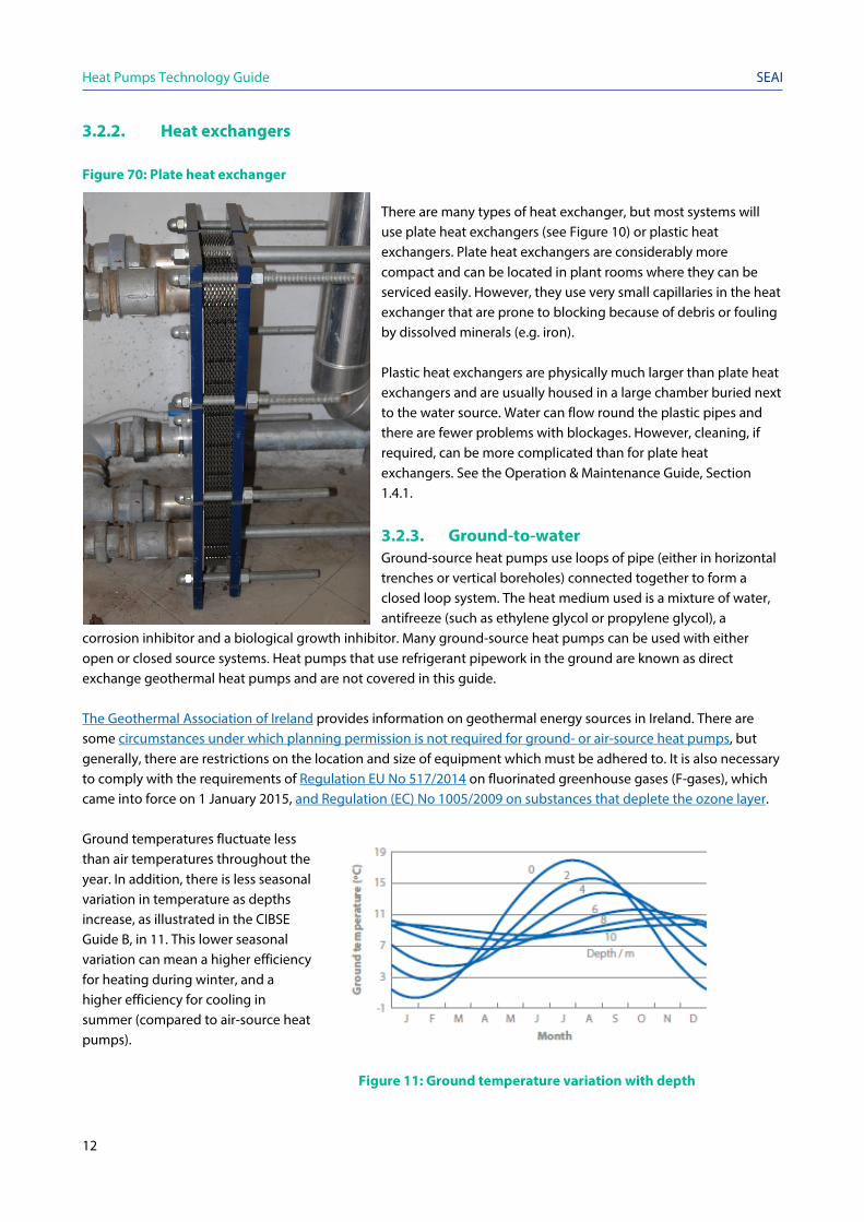
3.2.2. Heat exchangers Figure 70: Plate heat exchanger
There are many types of heat exchanger, but most systems will use plate heat exchangers (see Figure 10) or plastic heat exchangers. Plate heat exchangers are considerably more compact and can be located in plant rooms where they can be serviced easily. However, they use very small capillaries in the heat exchanger that are prone to blocking because of debris or fouling by dissolved minerals (e.g. iron). Plastic heat exchangers are physically much larger than plate heat exchangers and are usually housed in a large chamber buried next to the water source. Water can flow round the plastic pipes and there are fewer problems with blockages. However, cleaning, if required, can be more complicated than for plate heat exchangers. See the Operation & Maintenance Guide, Section 1.4.1.
3.2.3. Ground-to-water Ground-source heat pumps use loops of pipe (either in horizontal trenches or vertical boreholes) connected together to form a closed loop system. The heat medium used is a mixture of water, antifreeze (such as ethylene glycol or propylene glycol), a
corrosion inhibitor and a biological growth inhibitor. Many ground-source heat pumps can be used with either open or closed source systems. Heat pumps that use refrigerant pipework in the ground are known as direct exchange geothermal heat pumps and are not covered in this guide. The Geothermal Association of Ireland provides information on geothermal energy sources in Ireland. There are some circumstances under which planning permission is not required for ground- or air-source heat pumps, but generally, there are restrictions on the location and size of equipment which must be adhered to. It is also necessary to comply with the requirements of Regulation EU No 517/2014 on fluorinated greenhouse gases (F-gases), which came into force on 1 January 2015, and Regulation (EC) No 1005/2009 on substances that deplete the ozone layer. Ground temperatures fluctuate less than air temperatures throughout the year. In addition, there is less seasonal variation in temperature as depths increase, as illustrated in the CIBSE Guide B, in 11. This lower seasonal variation can mean a higher efficiency for heating during winter, and a higher efficiency for cooling in summer (compared to air-source heat pumps). Figure 11: Ground temperature variation with depth

Heat Pumps Technology Guide
13
SEAI
If you are considering installing a ground-source heat pump you should conduct a site visit. This informs the system design. Ideally, the site visit should include (see the accompanying Implementation Guide for a full list): • Site layout, ideally scale drawings showing the entire site and the types of ground cover (e.g. access roads,
hardstanding and grass); • Location and size of existing plant rooms and space for external heat pump components; • Information on the ground conditions of the site (test boreholes, trial pits, etc.); • Access for drill rigs and delivery of the system; and • Known environmental issues.
There are two types of ground-source heat pump systems: those which extract heat from the ground using pipework laid in horizontal trenches around 1 m to 2 m deep; and those which extract heat using loops of pipes installed in vertical boreholes. 3.2.3.1. Vertical boreholes Figure 12: Vertical boreholes
Vertical, closed loop collectors are installed in boreholes, each of around 100 m to 200 m deep. In each borehole, one or two loops of pipe are inserted vertically, and the borehole is backfilled with materials such as thermal grout. The number and depth of boreholes required depends on the heat pump capacity, the total amount of heat to be extracted per year and the type of rock/soil. Heat outputs typically vary from around 10 W/m to around 55 W/m of borehole. An indication of the different types of bedrock in Ireland can be found on the Geological Survey of Ireland website. Several factors affect the cost of boreholes. For example, on a site with solid consolidated rock overlain by superficial deposits, the greater the depth of superficial deposits (e.g. soil) that sit on top of the bedrock, the more casing is
needed and the greater the cost per borehole. Also, since some soil types can have poor thermal properties, more boreholes may be required. The thermal properties of the bedrock vary significantly depending on the rock type, but also depending on other factors: whether it is consolidated or highly fractured, and whether it is dry or there is a water flow through it. A borehole could penetrate through multiple rock types and superficial deposits. The heat output of each borehole depends on the thermal properties and the depth of the borehole. These have to be determined for each borehole in order to estimate heat output. A thermal response test may be performed on site in order to measure ground thermal properties, which may aid in system design and sizing. The heat recovery from closed loop boreholes in consolidated rock is from true geothermal energy (as well as from any groundwater flows). Therefore, the temperatures achieved tend to increase slightly with depth. However, there are practical limits to the depths of boreholes that can be drilled, depending on the rock type and the type of drilling used. You should conduct a desk-based assessment of the ground conditions to inform the feasibility and outline design, and then drill a test borehole to inform the detailed design.

Heat Pumps Technology Guide
14
SEAI
3.2.3.2. Horizontal loops
Figure 13: Vertical boreholes Horizontal ground loops can be installed in trenches of between 1 m and 2 m deep. Horizontal ground outputs are typically in the range of 5 W/m to 20 W/m of pipe but can be from 1 W/m to 40 W/m. The loops of pipe can be laid out in straight lengths or in coils, known as ‘slinkies’. Horizontal loops usually cost less to install than vertical boreholes, but they require a lot of ground area when providing space heating, usually several times the total floor area of a building being heated. For that reason, horizontal ground loops are typically not used for large systems. The soil type makes a big difference to the amount of heat that can be extracted per square metre. Soils that retain moisture tend to have higher heat outputs than well-draining soils (e.g. installations in dry sand will require several times more ground area than those in wet clay).
The specific heat extraction rate from ground loops can typically be between 10 W/m2 and 40 W/m2 of ground area.1 Horizontal trenches depend significantly on rainfall to replenish the heat extracted and cannot usually be installed under hardstanding. Closed loop system design In any closed loop system, the length and diameter of the ground loops are designed to cover sufficient ground area or include a sufficient number of boreholes. The hydraulic system design is also important. The number of pipe loops, the length of each pipe loop, the separation between pipes in the ground and the diameter of the pipe must all be determined to ensure sufficient flow through each loop. The flow must be fast enough to ensure good heat transfer, avoiding laminar flow and minimising pumping losses. Consideration should be given to how the choice of antifreeze affects the design. Some antifreeze products are more viscous than others and the viscosity can increase significantly at the temperatures reached in ground-source systems. The choice of antifreeze products must be considered with regard to environmental risk. There are other types of collectors, such as thermal piles, where pipework is installed in a building’s concrete piles. Advantages Since ground temperatures are lower in summer than air temperatures, ground-source heat pump systems have higher cooling efficiencies than air-source systems. Cooling is supplied directly (where the source system temperature is low and does not need further cooling), or by using a reversible heat pump system.
1 CIBSE TM51 2013b, Table 3.1.

Heat Pumps Technology Guide
15
SEAI
Injecting waste heat into the ground increases heat recovery, which improves heating efficiency. This strategy can also reduce the size requirements of the collector system, as heat is removed (in heating mode) and injected (in cooling mode) throughout the year. When a ground-source (or water-source) heat pump system replaces chillers for cooling, both cost and emissions can be significantly lower. The feasibility of this option should be considered at the design stage, to ensure that the design of the ground- (or water-) source system can accommodate it, the heat pump can be appropriately specified, and the hydraulic system in the building can be appropriately designed. Disadvantages In a ground-source heat pump system, particularly horizontal collectors, there is a finite thermal resource that can be depleted. Systems that extract only naturally occurring (renewable) heat depend on solar gain, rainfall or geothermal energy which may vary. That is why ground-source heat pumps are more sensitive to the operating hours, profile of heat supplied, and total heat delivered, than other types of heat pump. For example, particular care needs to be taken with delivering heat to dry out a new building after construction (e.g. if it has underfloor heating with solid floors). This can be a significant heat load that can deplete the ground energy store if it has not been not allowed for. Close to the surface, geothermal energy is negligible, so horizontal trenches rely on solar gain or rainfall to replace the heat extracted by the heat pump system. Excessive removal of heat (which exceeds the capacity of a site to recover the temperatures) can result in low ground temperatures around the heat source system, making the system inefficient. Solutions include: • Injecting waste heat; • Increasing the capacity of the ground-source system (if possible); and • Reducing the load on the ground-source system, for example by installing an air-source heat pump to provide
some of the heat.
Monitoring the amount of heat extracted (kWh) and the heat source temperatures using a heat meter can help to ensure that the system is operating within its design conditions. This also provides an early warning of any problems, so that remedial work can be planned. Ground-source heat pumps use antifreeze in the source loop to prevent it freezing. The viscosity of the antifreeze can vary significantly at low temperatures. So, if the source temperature does fall (e.g. because of lack of circulation caused by a blocked filter or an unexpectedly high heat load), this can increase the viscosity of the antifreeze, in turn increasing the pumping effort required. The increased pumping effort can mean that the optimum flow rates required are not achieved and the system stops working (low refrigerant pressure fault). The careful design and installation of monitoring equipment can identify these potential issues early on. More details are given in the accompanying Operation & Maintenance Guide.
3.2.4. Water-to-water Heat pumps can extract heat from surface water bodies including rivers, lakes and the sea, and from groundwater. Water-source heat pumps can be used at any scale, but the largest heat pump systems, which can be more than 10 MW, tend to use water sourced from the sea or major rivers.
Heat Pumps Technology Guide
16
SEAI
The amount of heat is typically constrained by: • The peak heat amount that can be extracted; and • The total amount of heat that can be extracted in a year. Rivers In a river system, the heat source is constantly replenished by the flow of the river. Therefore, the peak amount of heat that can be extracted under low river flow conditions will usually determine if a particular river can be used as a heat source. To calculate the peak amount of heat that can be extracted, it is necessary to know: • The capacity of the heat pump system; • Any environmental constraints, such as limits on the return temperature (cooling or heating the river); and • The flow rate of the river at different times of the year.
The river flow rate must be strong enough for the heat pump to work at all times of the year. The system is designed so that enough water from the river is pumped across the heat exchanger to prevent freezing. Several types of heat exchanger can be used. However, in general terms: • Water is extracted from the river and pumped through a heat exchanger; or • An array of pipework is laid in the river flow itself.
If the flow of water is insufficient or the heat exchanger is too small, then there is a risk of ice forming on the external heat pump unit. This can lead to system failure and heat transfer fluid leaks. Lakes and ponds In lakes and ponds, there is often no flow of water to replenish the heat extracted. Therefore, the main factor in determining whether the body of water is technically suitable is the total amount of heat that can be supplied by the heat pump in a year without lowering the source temperature to an unacceptable level. The sea For systems extracting heat from the sea, there is usually no limit on the total amount of heat that can be extracted. However, there are often major practical challenges. You should consult an experienced engineer if considering using this source. Groundwater When there is an aquifer beneath a site, boreholes can be drilled into the aquifer and water pumped out of it to extract heat. This is an open loop system. The water is usually then returned to the ground through a second borehole. Reinjecting the water into the same aquifer conserves the water resources. The capacity of a groundwater system depends on the water level recovery rate, the temperature of the groundwater and the nature of the groundwater flow. The amount of energy needed to pump the water can be significant and depends on factors such as the depth of the borehole and the permeability of the aquifer. The mapping tool on the Geological Survey of Ireland website shows the location of productive aquifers.

Heat Pumps Technology Guide
17
SEAI
3.2.5. Shared ground- or water-source system It is possible to connect multiple heat pumps to the same ground- or water-source system. This means that several buildings (or heat loads within a building) can share the source system and have individual heat pump and heat distribution systems suited to each building. Unlike heat networks, there is heat lost via the source pipework between buildings. Integrating heating and cooling loads into one source system can maximise energy efficiency through heat recovery, maximise the efficiency of the heat pump systems, and minimise the size and cost of the source array. Such systems have complex heat flow arrangements that will require software simulation of the loads to be met and the source system. You should seek professional engineering advice.
3.2.6. Other considerations
Intermediate brine loop On some open loop systems, an intermediate hydraulic loop is inserted between the heat pump and the open loop system. This protects the heat pump from the effects of freezing (if there is a lack of circulation and the heat pump does not turn off in time) and from being damaged by debris in the water. However, the intermediate circuit lowers efficiency, because the additional heat exchanger reduces the temperature in the evaporator by several degrees. Cooling Water-source heat pumps can be suitable for cooling in the same way as ground-source systems are (see the discussion in Section 3.2.1.). Large water-source systems that have open loop systems from the sea or a major river can have a much larger cooling capacity than similar ground-source systems.
3.3. Air-to-air There are air-source heat pump systems that can provide heat directly to air instead of through a water-based heat distribution system. These are often used for cooling (as air-conditioning systems) and are usually split or multi-split systems. This guide does not cover air-to-air heat pumps.

Heat Pumps Technology Guide
18
SEAI
4. Heat distribution systems and factors influencing their design
Key messages
• It is extremely important to accurately determine the heat load to be met by the heat pump. • Most heat pumps have a much lower flow and return temperatures than natural gas boilers, therefore
their mean radiator temperature is generally much lower than that of a boiler-fed system. For this reason, a heat pump system requires larger radiators. Correct sizing is very important.
• When installed in solid floors, underfloor heating systems are suitable for use with heat pumps in most instances due to the lower flow temperature of around 50 °C.
• Heating coils in air handling units should be sized on the flow and return temperatures of the heat pump.
• Some heat pumps cannot heat a hot water cylinder to 60 °C, the temperature at which Legionella is killed. In these cases, another method for controlling Legionella must be incorporated into the design of the system. This could be the periodic use of another heat source (such as an immersion heater) to heat the water to 60 °C, or the use of a specific high-temperature heat pump.
• Heat pumps tend to operate at lower temperature differences than many other heat sources. A smaller temperature difference requires a higher flow rate. As a result, it is important that (some or all of) the pipework diameter is large enough, and that the circulation pumps have enough capacity. This is true for new systems, and for retrofitting a heat pump to an existing property.
The design of the heat distribution system can significantly affect the heat pump performance. The first step in designing a heat distribution system is to determine the heating requirement. Data can then be obtained from manufacturers on the heat output of the heat pump at the required temperatures of the heat emitters. The lower the heat emitter temperature, the more efficient the system. Options for reducing these temperatures should be considered at an early stage of the design.
4.1. Accurate determination of heat load It is extremely important to accurately determine the heat load. For space heating and cooling, there is a methodology described in IS EN 12831 for calculating the design heat load of a building2 and design water load of a building.3 Process heating loads can be more difficult to determine and you should seek expert advice if considering this method.
4.2. Radiators
4.2.1. Oversizing standard steel radiators For a conventional boiler-fed system, radiators are typically sized using a temperature difference of 50 °C. This is the temperature difference between the space heating set point (e.g. 20 °C) and the mean radiator temperature (e.g. 70 °C). So, for example, with a natural gas boiler, the water temperature flowing to the radiator might be 75 °C and the exiting temperature 65 °C, giving a mean of 70 °C.
2 IS EN 12831 – 1 2017 3 IS EN 12831 – 1 2017

Heat Pumps Technology Guide
19
SEAI
As heat pumps have much lower flow and return temperatures than natural gas boilers, the mean radiator temperature is generally much lower than in boiler-fed systems, therefore the radiators often need to be larger. Standard steel radiators can be used with heat pumps, but they must have around three to seven times the output of a traditional boiler system, to allow for the lower flow temperature. This higher output can be achieved by increasing the length or height of a radiator, by increasing the number of panels, or by adding convector fins. Radiators are sized to meet the heating requirement of the space in which they are located, using manufacturers’ data for the appropriate smaller temperature difference (typical of heat pump systems). The manufacturers’ data is presented in tables of heat output at the lower temperature difference, or a conversion factor is provided to use with the data on heat output from standard boilers. The design process includes how the radiators will be mounted, e.g. wall-mounted or trench-heated.
4.2.2. Low-temperature radiators There are radiator types designed for higher heat output at low temperatures. Aluminium radiators provide better conductivity, and therefore higher heat output per area, than traditional steel radiators. This means that aluminium radiators can be more compact. However, they are usually more expensive. Radiators can be passive or active emitters. Passive radiators circulate air by free convection and are usually used in domestic properties. Active radiators force air flow by using fans. Radiators can be for heating only, or both heating and cooling. Fan-assisted active radiators for heating and cooling generally need two hydraulic circuits. Fan-assisted radiators are either wall-mounted or used in trench-heating systems (radiators in a trench around the periphery of a space, particularly at windows). Trench-heating radiators are suited to providing heating under large areas of glazing such as facades, either as the main source of heat or to supplement another heat emitter.
4.3. Hydronic underfloor heating
Figure 14: Installation of underfloor heating Wet (also known as hydronic) underfloor heating involves laying loops of plastic pipes (usually between 10 mm and 20 mm outside diameter) through which water is pumped. The pipes are either located inside a concrete floor or in grooved aluminium plates within a floor screed. The pipes are arranged in loops connected back to manifolds. A room can have one or more loops controlled by a thermostat. It is important that there is insulation under the heated screed to minimise downwards heat losses. Table 1 sets out the minimum level of floor insulation (m²·K/W) required to
minimise downward heat loss for different room types (according to BS EN 1264, the standard for designing underfloor heating).
Heat Pumps Technology Guide
20
SEAI
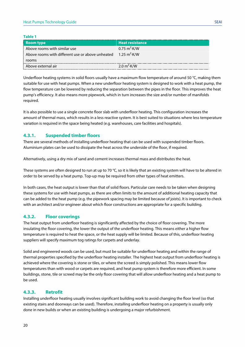
Table 1 Room type Heat resistance Above rooms with similar use 0.75 m²·K/W Above rooms with different use or above unheated rooms
1.25 m²·K/W
Above external air 2.0 m²·K/W Underfloor heating systems in solid floors usually have a maximum flow temperature of around 50 °C, making them suitable for use with heat pumps. When a new underfloor heating system is designed to work with a heat pump, the flow temperature can be lowered by reducing the separation between the pipes in the floor. This improves the heat pump’s efficiency. It also means more pipework, which in turn increases the size and/or number of manifolds required. It is also possible to use a single concrete floor slab with underfloor heating. This configuration increases the amount of thermal mass, which results in a less reactive system. It is best suited to situations where less temperature variation is required in the space being heated (e.g. warehouses, care facilities and hospitals).
4.3.1. Suspended timber floors There are several methods of installing underfloor heating that can be used with suspended timber floors. Aluminium plates can be used to dissipate the heat across the underside of the floor, if required. Alternatively, using a dry mix of sand and cement increases thermal mass and distributes the heat. These systems are often designed to run at up to 70 °C, so it is likely that an existing system will have to be altered in order to be served by a heat pump. Top-up may be required from other types of heat emitters. In both cases, the heat output is lower than that of solid floors. Particular care needs to be taken when designing these systems for use with heat pumps, as there are often limits to the amount of additional heating capacity that can be added to the heat pump (e.g. the pipework spacing may be limited because of joists). It is important to check with an architect and/or engineer about which floor constructions are appropriate for a specific building.
4.3.2. Floor coverings The heat output from underfloor heating is significantly affected by the choice of floor covering. The more insulating the floor covering, the lower the output of the underfloor heating. This means either a higher flow temperature is required to heat the space, or the heat supply will be limited. Because of this, underfloor heating suppliers will specify maximum tog ratings for carpets and underlay. Solid and engineered woods can be used, but must be suitable for underfloor heating and within the range of thermal properties specified by the underfloor heating installer. The highest heat output from underfloor heating is achieved where the covering is stone or tiles, or where the screed is simply polished. This means lower flow temperatures than with wood or carpets are required, and heat pump system is therefore more efficient. In some buildings, stone, tile or screed may be the only floor covering that will allow underfloor heating and a heat pump to be used.
4.3.3. Retrofit Installing underfloor heating usually involves significant building work to avoid changing the floor level (so that existing stairs and doorways can be used). Therefore, installing underfloor heating on a property is usually only done in new builds or when an existing building is undergoing a major refurbishment.

Heat Pumps Technology Guide
21
SEAI
Installing a solid floor on the ground floor of a building with a suspended timber floor can be one method of installing renewable heat in hard-to-treat buildings, particularly where stone or tiles are used. In this case, the floor is removed and the void below filled with a damp-proof membrane, hard core, insulation and a concrete slab. This requires an architect or structural engineer to design a system suitable for the specific building, one that is compliant with building regulations.
4.4. Integrating heating, ventilation and air-conditioning Air handling units regulate and circulate air as part of a heating, ventilation and air-conditioning system. They typically contain a fan to circulate air, a heating coil to supply heat to air and a cooling coil to remove heat from air as required. The heating coil should be sized according to the flow and return temperatures of the heat pump. Generally, this increases the size of the heating coil, compared to the boiler-fed system equivalent. When retrofitting a heat pump to an existing air handling unit, space constraints may restrict the size of the heating coil and the temperatures that can be achieved. In this case, it may be necessary to upgrade the unit. Ceiling cassettes can be refrigeration (multi-split air-to-air) or hydraulic. Like air handling units, ceiling cassettes provide heating and cooling to spaces. A key design consideration is the size of the coils.
4.5. Hot water provision The design of the hot water system depends on the temperature that can be supplied by the heat pump. Some heat pumps cannot heat a hot water cylinder to 60°C, the temperature at which Legionella is killed. As such, a method of controlling Legionella must be incorporated. This could be the periodic use of another heat source (such as an immersion heater) to heat the water to 60°C or a high-temperature heat pump. Similarly, it is necessary to heat any storage cylinders to 60°C. The frequency of this depends upon the situation, but it is usually done at least once per week. Refer to the National Guidelines for the Control of Legionellosis in Ireland, 20094 and the Approved Code of Practice on Legionnaires’ disease5 for further guidance. Legionellosis is a collective term for diseases caused by Legionella bacteria. The most serious of these is Legionnaires’ disease. Pontiac fever and Lochgoilhead fever are similar to Legionnaires’ disease, but less serious. Outbreaks are caused by exposure to Legionella, found in water maintained at a temperature high enough (20 °C to 45 °C) to encourage the growth of the bacteria. Examples include showers, cooling towers, evaporative condensers, hot- and cold-water systems, and spa pools. In all cases, it is essential to heat the storage cylinder to 60 °C, the temperature at which Legionella is killed. Water stored in a hot water cylinder must be heated frequently enough to eliminate Legionella. The required frequency varies according to each situation, but it is usually necessary to heat storage cylinders to 60 °C at least once a week. Some heat pumps cannot heat a hot water cylinder to 60 °C. In these cases, another method for controlling Legionella must be incorporated into the design of the system. This could be the periodic use of another heat source (such as an immersion heater), or the use of a specific high-temperature heat pump. The use of a backup heater lowers the overall efficiency of the system. Refer to the National Guidelines for the Control of Legionellosis in Ireland, 2009 and the Approved Code of Practice on Legionnaires’ disease for further guidance.

Heat Pumps Technology Guide
22
SEAI
Heating system design (including the hot water cylinder and the distribution pipework) must minimise the risk of Legionella. Design strategies include avoiding dead-legs (where water accumulates in a pipe that is seldom used, e.g. a shower at the end of a building that is no longer used). Where dead-legs cannot be avoided they must be flushed regularly. Thorough assessment is important when retrofitting a heating system. The hot water cylinder should be sized for the hot water load. A heat pump system may need a larger hot water cylinder than a natural gas boiler system, and will require a larger heat exchanger, so this should be checked if the original cylinder is to be retained. An alternative approach is to have a thermal store, typically in the same hydraulic circuit as that of the heating loop, with instantaneous water heating upon demand via a heat exchanger. This avoids hot water storage and reduces the risk of Legionella. The temperature of the hot water generated is typically 2 °C to 4 °C cooler than the temperature of the water in the thermal store. The heat exchanger should be sized for maximum flow rate, making it less suitable for very high flow rate applications.
4.6. Process and other heat use Where heat is used for process applications, the requirement of the process plant must be met. As when using a heat pump system for space heating, reducing the flow and return temperatures to the heat pump increases efficiency. Therefore, heat pumps are suited to processes with low temperature heat uses (e.g. swimming pools). Higher temperatures can be met efficiently at a larger scale (e.g. a seasonal performance factor of 3 can be achieved at 70 °C if the heat pump is greater than 1 MW, or at 90 °C if the heat pump is greater than 10 MW). These are specialist applications and should be discussed with a consultant.
4.7. Pipework and pumps In any heat distribution system, the circulating pumps must provide the required flow rate of water while overcoming the pressure loss across the system. If the flow rate increases, the pressure loss will also increase, often significantly. Heat pumps tend to operate at lower temperature differences than many other heat sources. A smaller temperature difference means that an increased flow rate is needed. Energy efficiency measures reduce heat load, this needs to be factored in when retrofitting, and increasing the size of the pipes should also be considered as part of the retrofit. It is important to minimise the pressure losses across the pipework and components. Circulating pumps have to be correctly specified and sufficient to distribute the heat required, to make sure the heat pump will stay within its optimum design. Minimisation of pressure losses can be tackled in a number of ways. Assuming that the length of the circuits and the pressure loss across all other items (e.g. radiators) in the existing heating distribution system stay the same when the heat pump is installed, then the choice is likely to be between: 1. Increasing the diameter of some or all of the pipework, or 2. Increasing the capacity of the circulation pumps. Changing the pumps is likely to change electricity consumption (it will drop if the new pump is more efficient). In practice, the pressure loss across the other system components is also likely to change, as some of the heat emitters are likely to change. Usually it is necessary to reassess the entire system. A pressure test of existing pipework and a power flush helps to determine what repairs or replacements are necessary.
Heat Pumps Technology Guide
23
SEAI
Another option is splitting one hydraulic circuit into several circuits. This means the system can operate at a lower temperature difference. This option is much cheaper than upgrading all the pipework and it can be combined with control improvements to provide further benefits. The system must have enough expansion capacity. A design engineer calculates the volume of the system, taking into account the working fluid and any additives (e.g. the antifreeze agent, ethylene glycol), and the temperature range of the system.
4.8. Antifreeze In some systems, particularly air-source heat pumps, part of the heating system is outdoors. This outside pipework must be insulated. However, there can be times (such as during a power cut) when the system will be off, which means that even with good insulation on the pipework, there is a risk of freezing. One way of mitigating this risk is to use antifreeze in the system. However, antifreeze usually has to be quite concentrated (20% to 40% by volume), meaning that it is expensive to treat the whole system. Adding antifreeze also changes the viscosity of the water. In turn this changes the pumping requirements and also means that heat meters should be recalibrated. For these reasons, some systems use an intermediate circuit (on the heat distribution system between a heat pump located outside and the plant room inside the building), and only use antifreeze in this intermediate circuit. A plate heat exchanger or coil in a buffer tank separate the intermediate circuit from the rest of the heat distribution system.
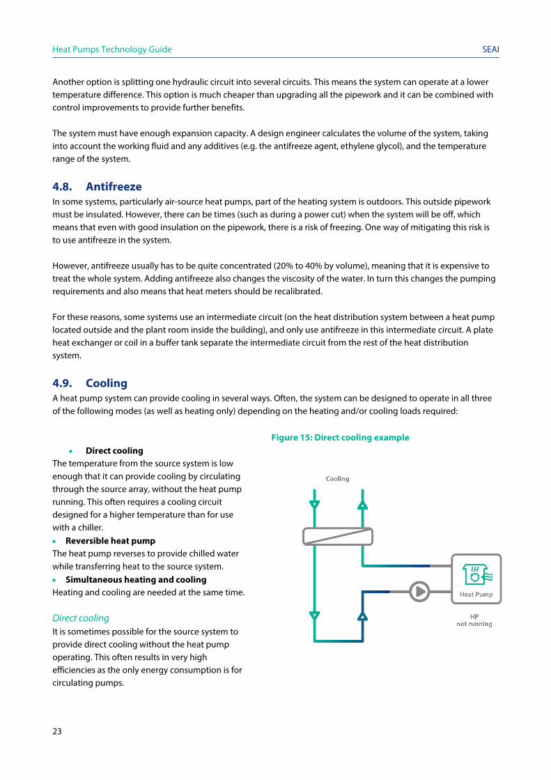
4.9. Cooling A heat pump system can provide cooling in several ways. Often, the system can be designed to operate in all three of the following modes (as well as heating only) depending on the heating and/or cooling loads required: Figure 15: Direct cooling example
• Direct cooling The temperature from the source system is low enough that it can provide cooling by circulating through the source array, without the heat pump running. This often requires a cooling circuit designed for a higher temperature than for use with a chiller. • Reversible heat pump The heat pump reverses to provide chilled water while transferring heat to the source system. • Simultaneous heating and cooling Heating and cooling are needed at the same time. Direct cooling It is sometimes possible for the source system to provide direct cooling without the heat pump operating. This often results in very high efficiencies as the only energy consumption is for circulating pumps.
Heat Pumps Technology Guide
24
SEAI
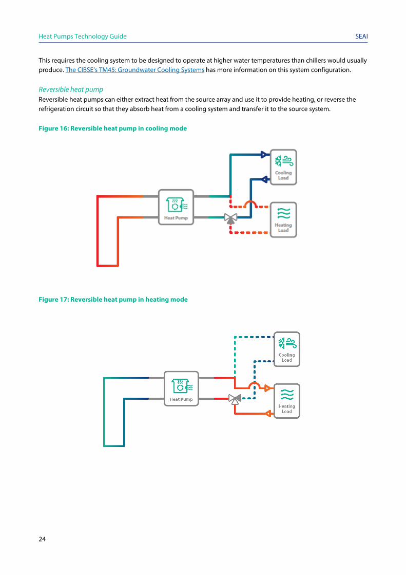
This requires the cooling system to be designed to operate at higher water temperatures than chillers would usually produce. The CIBSE’s TM45: Groundwater Cooling Systems has more information on this system configuration. Reversible heat pump Reversible heat pumps can either extract heat from the source array and use it to provide heating, or reverse the refrigeration circuit so that they absorb heat from a cooling system and transfer it to the source system. Figure 16: Reversible heat pump in cooling mode
Figure 17: Reversible heat pump in heating mode
Heat Pumps Technology Guide
25
SEAI
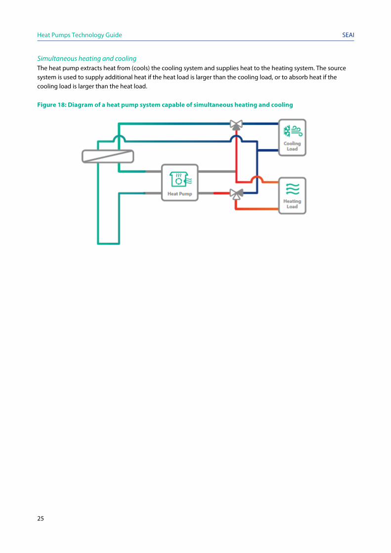
Simultaneous heating and cooling The heat pump extracts heat from (cools) the cooling system and supplies heat to the heating system. The source system is used to supply additional heat if the heat load is larger than the cooling load, or to absorb heat if the cooling load is larger than the heat load. Figure 18: Diagram of a heat pump system capable of simultaneous heating and cooling

Heat Pumps Technology Guide
26
SEAI
5. Integration with other heat sources
Key messages
• Particular care needs to be given to integrating higher temperature heat sources into a system containing a low-temperature heat pump. The hydraulic design and controls must enable the heat pump to operate within its performance envelope.
• There are two main operating modes for systems with another heat source: • Bivalent parallel The heat pump and backup heat source operate at the same time. • Bivalent alternative The heat pump and backup heat source operate alternately.
Heat pumps may be used alongside other heat sources for various reasons, such as: • The capacity of a heat pump system is limited due to electricity supply constraints and so another heat source
provides the extra heating capacity required; • A heating system or process may periodically require a temperature that the heat pump cannot achieve (e.g. for
a Legionella cycle); or • A backup system is needed. Particular care needs to be given to integrating higher temperature heat sources into a system containing a low-temperature heat pump. The hydraulic design and controls of a system must enable the heat pump to operate within its performance envelope and take account of the flow rate, the temperature difference across the system, and include the temperature difference and flow rate required for any other heat generator in the system. The temperature difference required for boilers is often much higher (e.g. over 50 °C) than that needed for a heat pump system. The different operating parameters of the two heat sources are usually accommodated by measures such as: • Using plate heat exchangers as a thermal break so that a boiler can maintain higher flow and return temperatures
than the system being heated; • Using low loss headers, which allow different flow rates between source and heat use; or • Using buffer vessels. Simply connecting a heat pump in parallel with a boiler without considering the differences in flow rates and temperatures results in operational problems. The heat pump may not be able to run or restart when the backup heat source is running. This means the heat pump does not provide the anticipated heat load and therefore reduces cost and carbon savings.

Heat Pumps Technology Guide
27
SEAI
There are two main operating modes for systems with another heat source (known as bivalent systems): • Bivalent parallel The heat pump and backup heat source operate at the same time. • Bivalent alternative The heat pump and backup heat source operate alternately.
Figure 19: Bivalent parallel and bivalent alternative
5.1. Bivalent parallel In theory, bivalent parallel mode maximises the use of the heat pump by ensuring constant use alongside the backup heat source. An example of this is where a building has a low-temperature heat distribution system, but a restriction on the available electricity supply prevents a heat pump of sufficient capacity from being installed. In practice, the system has to be carefully designed to allow both heat sources to operate in parallel. It is quite common for a backup boiler to exceed the operating temperature limits of the heat pump and prevent it from operating. Care needs to be taken with the heat distribution system. Some heating circuits require mixing arrangements to prevent exposure to higher temperatures than a heat pump can withstand. For example, in an underfloor heating system, the flow temperature in the system may need to be limited to 50 °C or 55 °C to avoid damage to the floor. While a heat pump cannot exceed this temperature, a boiler can. This risk must be managed.
5.2. Bivalent alternative In bivalent alternative mode, the heat pump switches off for a period of time and the load is met by other heat sources. An example of this is when the flow temperature required is higher than the heat pump can provide. In space heating systems, this could be triggered by the outside temperature dropping below a predetermined value. In process heating, it could be a request for a higher temperature from a system controlling a piece of the process plant. It is important to carefully control the temperatures in the system, so that once the flow temperature required reduces to the point where it can be supplied by the heat pump, then the heat pump takes over.
020406080
100120140160
00:0
0:00
01:3
0:00
03:0
0:00
04:3
0:00
06:0
0:00
07:3
0:00
09:0
0:00
10:3
0:00
12:0
0:00
13:3
0:00
15:0
0:00
16:3
0:00
18:0
0:00
19:3
0:00
21:0
0:00
22:3
0:00
Bivalent Alternative
Heat pump Backup
020406080
100120140160
00:0
0:00
01:3
0:00
03:0
0:00
04:3
0:00
06:0
0:00
07:3
0:00
09:0
0:00
10:3
0:00
12:0
0:00
13:3
0:00
15:0
0:00
16:3
0:00
18:0
0:00
19:3
0:00
21:0
0:00
22:3
0:00
Bivalent Parallel
Heat pump Backup

Heat Pumps Technology Guide
28
SEAI
6. Controls
Key messages
• Weather compensation can be used in any system. By avoiding the system cycling on and off, it improves energy efficiency and comfort.
• Some heat pump compressors have speed control, which enables the heat pump to reduce output. • Reducing the number of starts (by using controls) means less wear on the system’s components and
lower buffer capacity requirements.
6.1. Weather compensation The output of heat emitters depends on their mean water temperature. When the water temperature is lower, the heat emitter system produces less heat. Weather compensation means reducing the water temperature in the heat emitter system as the outside temperature increases. Deliberately reducing the temperature in the heating system can be useful when the outside temperature is relatively mild but the building still needs heating. Weather compensation can be used in any system to improve energy efficiency and comfort. It stops the system from cycling on and off. Weather compensation in a heat pump system has an added bonus because the heat pump operates more efficiently at a lower temperature. There are also disadvantages to weather compensation. The system can be slow to respond to changes in outside temperature, so if outdoor temperature changes rapidly there is usually a lag time in the system response. A weather compensation system has to be set up at the commissioning stage, and can be tweaked later on.
6.2. Speed control Some heat pump compressors have speed control to reduce heat pump output. These systems are different to a fixed output heat pump in a number of ways. They require a different expansion valve, for example. Retrofitting existing heat pumps to include speed control is usually not possible. Many heat pumps simply operate on an on/off basis, with no modulation possible in each circuit. In systems incorporating several heat pumps, or for heat pumps containing several refrigeration circuits, output is controlled by turning individual circuits on or off. These approaches reduce the number of starts needed, which means less wear on the system’s components and lower buffer capacity requirements.

Heat Pumps Technology Guide
29
SEAI
7. Buffers tanks and thermal stores
Key messages
• The purpose of a buffer tank is to decouple the operation of the heat pump from the building’s heat load. This optimises both comfort in the building and the heat pump operation.
• Thermal stores hold the heat generated by heat pumps for later use. The size of the thermal storage determines what can be achieved with a particular system. Most heat pumps operate with small differences between flow and return temperatures and therefore need large thermal stores.
• Heat can be stored under the ground using a ground array. This can be either in consolidated rock using closed loop boreholes or, in an open loop system, in an aquifer. In systems that are supplying a lot of cooling in summer and heating in winter, the design can be optimised to ensure that the system stores as much of the transferred heat as possible.
The terms ‘buffer tank’ and ‘thermal store’ are frequently used interchangeably. This is a source of confusion, as their purpose differs between renewable heat technologies. In these guides, the following definitions are used: Buffer tanks The purpose of a buffer tank is to decouple the operation of the heat pump from the heat load in the building, in order to optimise both comfort in the building and heat pump operation. In practice, this means reducing the number of heat pump stop-start cycles under part-load conditions since most heat pumps can only be on (full output) or off (no output). Also, heat pump manufacturers often set minimum run times for their products, during which the generated heat must be removed.
The buffer tank meets the heat load in the system and the heat pump turns on and off in a controlled manner to ensure that the buffer is kept sufficiently charged while reducing the number of stop-start cycles. This reduces wear and improves efficiency. Depending on the hydraulic design, a buffer can be connected in parallel with the heat pump flow and return, or just with the return. Thermal stores Thermal stores are used to store the heat generated by heat pumps for later use. While, like a buffer tanks, they reduce the number of stop-start cycles, thermal stores generally operate on a longer time frame, and tend to be significantly larger than a tank simply used as a buffer. Another difference between thermal stores and buffer capacity is the way in which the tank can be connected. A thermal store is connected so that the flow and return from the heat pump and to the heating system are connected to the tank. Where a thermal store is included in a design, it will normally be configured to also perform the role of a buffer tank. Thermal stores enable:
• A smaller heat pump to be specified to meet larger peak demands, provided the heat pump has enough time to recharge the store sufficiently between peaks (i.e. the peaks need to be relatively short);
• Domestic hot water (DHW) production by heating cold water via a plate heat exchanger that draws heat from the thermal store (typically between 55 ºC and 60 ºC) on demand. This allows the instantaneous domestic hot water production to be provided at around 45 ºC and reduces the risk of Legionella by eliminating the need for domestic hot water storage; and
• Heat to be generated at a time when electricity unit prices are lower, such as at night.

Heat Pumps Technology Guide
30
SEAI
7.1. Operation Manufacturers’ guidelines should be used to determine buffer capacity or minimum run time. Minimum run time should take into account a system’s ability to control a cascade of heat pumps (e.g. a 4 x 100 kW system would need a buffer for 400 kW or 100 kW depending on the manufacturer’s guidelines and the control system in place). As an example, a 100 kW heat pump operating at a temperature difference of 5 °C with a minimum run time of 20 minutes, would require a buffer of 5,700 litres. Whereas a 100 kW heat pump operating at a temperature difference of 7 °C with a minimum run time of 7 minutes, would require a buffer capacity of 2,050 litres. There are systems where the hot water in the heating system accounts for some of the buffer capacity, but this depends on the control system. If only one small area (such as an entrance hallway) is heated, then the actual volume circulating may be a very small proportion of the whole system. In this case, the total system volume does not contribute to the minimum buffer capacity. The size of the thermal storage determines what can be achieved with a particular system. As most heat pumps operate with small differences between flow and return temperatures, they require very large stores. Transcritical heat pumps (described in Section 2.2.2.), operating at higher temperature differences, can use smaller stores, but this can mean lower efficiency. Depending on the hydraulic design, a buffer can be connected in parallel with the heat pump flow and return, or just in the return. For air-source systems with a thermal store or buffer tank, the defrost cycle can use heat generated by the heat pumps. This reduces (or eliminates) the need for electrical resistant heaters for the defrost cycle.
7.2. Seasonal thermal stores Heat can be stored under the ground using a ground array. This is either in consolidated rock using closed loop boreholes or, in an open loop system, in an aquifer. In both cases, the principle is the same: waste heat (such as from cooling) is injected into the ground at one time of year (usually summer). This heats up the ground, and increases the source temperature for when the heat pump is in heating mode. In systems supplying a lot of cooling in summer and heating in winter, the design can be optimised to ensure that the system retains as much of the transferred heat as possible. Strategies here include designing the layout of the array of closed loop boreholes to ensure heat recovery is optimised. In a heating-only system, boreholes are often laid out in a line to maximise heat recovery. The same system using seasonal thermal storage can be designed so that the boreholes are in a triangular grid. For these systems, it is essential to run a simulation of the borehole system using appropriate borehole design software.
Heat Pumps Technology Guide
31
SEAI
8. Metering
Key messages
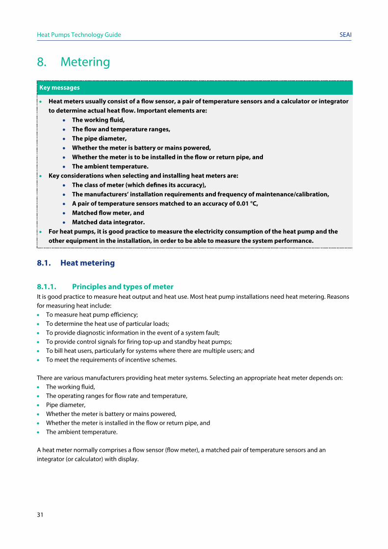
• Heat meters usually consist of a flow sensor, a pair of temperature sensors and a calculator or integrator to determine actual heat flow. Important elements are:
• The working fluid, • The flow and temperature ranges, • The pipe diameter, • Whether the meter is battery or mains powered, • Whether the meter is to be installed in the flow or return pipe, and • The ambient temperature.
• Key considerations when selecting and installing heat meters are: • The class of meter (which defines its accuracy), • The manufacturers’ installation requirements and frequency of maintenance/calibration, • A pair of temperature sensors matched to an accuracy of 0.01 °C, • Matched flow meter, and • Matched data integrator.
• For heat pumps, it is good practice to measure the electricity consumption of the heat pump and the other equipment in the installation, in order to be able to measure the system performance.
8.1. Heat metering
8.1.1. Principles and types of meter It is good practice to measure heat output and heat use. Most heat pump installations need heat metering. Reasons for measuring heat include: • To measure heat pump efficiency; • To determine the heat use of particular loads; • To provide diagnostic information in the event of a system fault; • To provide control signals for firing top-up and standby heat pumps; • To bill heat users, particularly for systems where there are multiple users; and • To meet the requirements of incentive schemes.
There are various manufacturers providing heat meter systems. Selecting an appropriate heat meter depends on: • The working fluid, • The operating ranges for flow rate and temperature, • Pipe diameter, • Whether the meter is battery or mains powered, • Whether the meter is installed in the flow or return pipe, and • The ambient temperature. A heat meter normally comprises a flow sensor (flow meter), a matched pair of temperature sensors and an integrator (or calculator) with display.

Heat Pumps Technology Guide
32
SEAI
8.1.2. Flow sensors Figure 20: Flow sensor
There are various types of flow sensor available, the most commonly used in heat meters are: • Ultrasonic flow sensors, which measure the transit time of the sound in the moving fluid between an upstream and downstream sensor. They are non-invasive and low maintenance. However, they need relatively long unimpeded upstream pipework for accurate measurement. • Fluid oscillatory flow sensors, which fall into two groups – vortex shedding
flow sensors and fluidic oscillatory flow sensors. In the former, a buff body in the fluid stream causes the shedding of vortices on alternate sides of the body; the frequency of which is proportional to the fluid velocity. In fluidic oscillatory flow sensors, a jet enters a separate chamber and oscillates between two feedback channels, at a frequency proportionate to the main fluid flow velocity.
The choice of flow sensor will depend on the heating medium, the accuracy required, and the cost and practicalities of fitting the flow sensor within the installation.
8.1.3. Temperature sensors Temperature sensors are supplied as matched pairs and are calibrated to minimise the margin of error in measuring the temperature difference between flow and return streams. Temperature sensors are normally of the platinum resistance temperature detector type PT100 or PT500.6 To maintain accuracy, it is important that the temperature sensors are positioned correctly, usually within thermal pockets and that their cables are not altered.
8.1.4. Integrators The heat meter integrator determines the instantaneous heat flow by using the flow rate of the heating fluid, the temperature difference between the flow and return, and the specific heat capacity of the heating fluid. Integrating this over time gives the cumulative heat consumption of the heating circuit (in kWh, MWh or GJ). As well as displaying the heat consumption, most integrators can provide other useful parameters, such as the instantaneous rate of heat use, flow and return temperatures, and the flow rate of the heating fluid. Furthermore, many integrators can store historical data (e.g. 18 months of month-end cumulative heat data), and also output/download their data to other monitoring systems, such as building management systems. Depending on the manufacturer, heat meters can be configured for a number of communication protocols (such as Meter-Bus (M-Bus) and RS 232) by adding modules to the integrator.
6 PT100 means that the RTD has a resistance of 100Ω at 0ºC. A PT500 RTD has a resistance of 500Ω at 0ºC. Higher resistance RTDs have lower errors for the same cable types, which is important where longer cable lengths are needed.

Heat Pumps Technology Guide
33
SEAI
Figure 21: Typical heat meters Heat meter calibration, depending on the meter type, is specific to the heat transfer fluid in the circuit being measured. This is normally water but can be water with antifreeze and/or a corrosion inhibitor. Generally, corrosion inhibitors do not require meter recalibration, but glycol antifreeze mixtures do. In either case, the heat meter supplier or manufacturer should be consulted. If additives are present for which meters have been specifically calibrated, then it is important that the level of concentration is maintained through regular checking and topping up. Automatic systems are available to achieve this. Some meters are specifically manufactured for use with water-glycol mixtures and the glycol concentration can be entered directly into the meter rather than having to be specifically calibrated by the manufacturer or authorised agent.
8.2. Meter classifications Heat meters should meet the requirements of the Measuring Instruments Directive (2004/22/EC) (MID). If they comply, then they will have a CE mark. IS EN 1434:2007, Parts 1 to 6 is the Irish implementation of EN 1434:2007, which is harmonised to the Measuring Instruments Directive. Part 1: General requirements and Part 6: Installation, commissioning, operational monitoring and maintenance will be of most value to readers of this guide. In addition, heat meter accuracy is specified by the Measuring Instruments Directive class notation, where accuracy is defined in terms of Class 1, 2, or 3 – 1 being the most accurate. The accuracy of the meter in practice will also depend on it being installed in line with the manufacturer’s instructions. A poorly installed meter will not be accurate. When selecting and installing heat meters, consider: • The accuracy class of meter; • The need for the flow sensor, temperature sensors and integrator to be matched; • The suitability for the static pressures and flow rates of the circuits where they are to be installed; • The fact that, for open vented systems, low pressure and the presence of air can mean that an ultrasonic flow
sensor is not appropriate; • The correct positioning of flow sensors in relation to pumps, bends, etc. and flow sensor orientation; and • The installation of temperature sensors in accordance with the manufacturer’s guidelines.
8.3. Installation Generally, heat meter integrators need to be protected from outside elements. This can be done by installing them on pipework in buildings or, if outside installation is necessary, housing them within weatherproof boxes (unless the heat meter integrators are suitably IP7 rated).
7 IP stands for ‘international protection’, but is commonly referred to as ‘ingress protection’

Heat Pumps Technology Guide
34
SEAI
Heat meter components must be installed correctly to ensure the accurate measurement of the target heat flow. Manufacturers will specify the requirements for each meter. Failure to observe these may lead to inaccurate measurements. For example: • Ultrasonic flow meters must normally be installed with the sensor head orientated within +/- 45 o of the
horizontal. • Flow meters may also be sensitive to the direction of flow. In such cases, the flow meter will have direction marks
on the body of the meter. These should match the direction of flow. • Heat meter manufacturers usually specify whether the flow sensor should be installed in the flow or return
pipework.
There may be restrictions on where flow meters can be fitted in the pipework system. Examples are: • Mechanical meters should not be located within five pipe diameters of bends or other disturbances, and the
manufacturer’s instructions should be adhered to. • Ultrasonic meters should not be placed where there is a risk of air build-up, nor near a pump inlet or discharge
point.
Temperature sensors are supplied as matching pairs, and the serial numbers on the hot and cold temperature sensors should match. Temperature sensors should be correctly installed within their thermal pockets. Thermal paste can be used to ensure good contact between the sensor and the wall of the thermal pocket. The sensors should not be able to move once installed. It is good practice for the meter installer to fit the temperature sensors and calculators with security tags. This shows that the meter has not been tampered with. Such practices may be required by a financial incentive scheme. Temperature sensors and their leads are particularly susceptible to damage, so care should be taken in the choice of location for the thermal pockets, and in the positioning and securing of the sensor leads. The detailed design and installation must ensure that the temperature sensors are located to measure the intended heat flow. Incorrect positioning of one or both sensors will lead to erroneous heat measurement.
8.4. Maintenance and calibration Heat meters should be supplied with calibration certificates. Ideally, these calibration certificates should be valid for a set time period. However, manufacturers do not always state recalibration intervals or expected meter lifetimes, even on their calibration certificates, and there is no requirement in the Measuring Instruments Directive or EN1434 to do so. In the absence of guidance from the manufacturer, a period of no more than 5 years between recalibrations would be considered good practice. The calibration should be appropriate to the heating medium. For example, if it is to be used to measure the flow of a water/glycol mixture then the flow meter should have been calibrated for that mixture. Flow meters also require maintenance in order to ensure that they do not become less accurate over time. Recalibration usually requires that the flow meter is removed and returned to the manufacturer or a test house approved by the manufacturer. This will result in downtime for the installation (drain-down, refill and re-pressurisation) unless there is a way of by-passing the meter. It may be more economical to buy a new meter, perhaps as part of an exchange with the manufacturer. Records of all meter calibrations, repairs and changes should be maintained.

Heat Pumps Technology Guide
35
SEAI
8.5. Electricity metering For heat pumps, it is good practice to measure the electricity consumption of the heat pump and other equipment in the heat pump installation. This helps to: • Determine heat output of the heat pump to monitor the coefficient of performance, seasonal performance factor,
and seasonal coefficient of performance; • Determine the cost of operating the heat pump system; • Provide diagnostic information in the event of a system fault; and • Meet the requirements of incentive schemes.
Consumption is measured via electricity meters installed to measure the electricity supplied to the heat pump system. Data from the meters should be synchronised with the metered heat generation/usage data. The following parameters should be checked to ensure that an electricity meter is suitable for a particular application: • Single or three-phase operation • Supply voltage • Current range Electricity meters must meet the requirements of the Measuring Instruments Directive. If they comply, they will have a CE mark. Under the Measuring Instruments Directive, electricity meters are classified according to their accuracy (Class A, B or C, with C being the most accurate).
8.6. Data logging As well as being useful for billing or compliance, heat meters and electricity meters provide valuable data on the heat pump system operation. This is very useful for monitoring system performance and detecting faults. Many meters can log data. Data loggers can be external, receiving an output through interfaces such as Meter-Bus (MBus) or Modbus. Alternatively, data loggers can be internal, storing data on built-in memory or removable storage (e.g. an SD card). On larger, more sophisticated systems, integrating heat meters into larger monitoring systems means they can be used for continuous monitoring. However, even on small, relatively straightforward systems, data logging from installed meters can be extremely valuable. When data logging functionality is being installed on a heat meter, it is often possible to log (in addition to the heat meter reading) the temperature from the two temperature sensors and the flow rate from the flow meter. This data is much more beneficial, particularly when combined with electricity meter readings. Using heat meter readings at the flow and return points of the source loop of ground-source systems enables monitoring and analysis of the temperatures (to check if they are reducing or increasing year on year), temperature difference (blockages can cause reduced flow rates and increased temperature differences across the source loop) and total heat extracted over a year.

Heat Pumps Technology Guide
36
SEAI
9. Electricity supply issues
Key messages
• The maximum import capacity of the incoming electrical supply to the site must be sufficient to accommodate the extra electricity demand of the heat pump system.
• Peak load depends on the size of heat pump and the motor controls installed. Generally, heat pumps with a rated thermal output of more than 15 kWth will require a three-phase supply.
Heat pumps are electrically powered and so any installation, including associated ancillary equipment (e.g. circulating pumps, cooling fans and defrost heaters) increases a site’s electricity supply load. That’s why it is important to make sure that the8 Maximum Import Capacity (MIC) of the incoming electrical supply is sufficient to accommodate the additional electricity demand of the heat pump system. Similarly, the site’s own internal distribution circuit(s) to which the system is to be connected must have sufficient capacity. The main electrical load in a heat pump is due to the motor that drives the compressor. At start-up, the compressor motor momentarily draws a higher current (and thus power) than in normal operational mode. This peak load depends on the size of the heat pump and the motor controls installed. The starting current of compressor motors is usually controlled by a soft starter or variable speed drive. Depending on existing loads, the site’s power factor could also be affected by a heat pump installation and may require correction. Generally, heat pumps with a rated thermal output of more than 15 kWth will require a three-phase supply. However, there are some systems available, with outputs of up to around 20 kWth and containing two heat pumps in one unit, which can automatically manage the current drawn so that a single-phase supply can be used. In marginal situations where a small increase in electrical supply capacity is required, but the cost of bringing in the extra electricity supply makes the heat pump system installation economically unviable, it may be possible to implement bespoke intelligent control of the heat pump operation to limit the maximum load. It is always necessary to discuss electricity supply with the prospective maximum import capacity heat pump supplier and the electricity distribution system operator (ESB Networks). This holds even when the Maximum Import Capacity ( and site distribution circuits appear to be adequate. It is important that the electrical loads are balanced for a three-phase motor (compressor) to run correctly. Loads on the phases must be balanced within the installation. It is important that the loads on the rest of the site are also balanced. This avoids significant differences between the phases, an important aspect, which can otherwise cause operating problems and compressor failure. The electricity tariff should be suited to the heat pump system and its operating schedule. For example, if night storage electric heaters are replaced by a heat pump system in a building that needs all of its heat during the day, then the new electricity tariff selected should take this into account. In this case, failing to change the tariff would mean unnecessarily expensive electricity.

Heat Pumps Technology Guide
37
SEAI
Appendix 1: Heat pump concepts
A.1. Concepts To upgrade heat, heat pumps and refrigeration systems exploit the following properties of gases: • When a gas expands it cools. If a gas is in a vessel at high pressure and at the temperature of the air around the
vessel, and the pressure is rapidly reduced, the temperature of the gas in the vessel will decrease. This effect can be observed by spraying an aerosol can: the can gets cooler as the gas rapidly expands from the high pressure inside the can to the atmospheric pressure outside.
• When a gas is compressed it gets warmer. If a gas is in a sealed container at ambient temperature and the
pressure is increased, the gas gets warmer. The amount that a gas heats up as the pressure is increased varies between gases. Figure 20 shows the relationship between temperature and pressure for common refrigerant gases.
Figure 22: Relationship between temperature and pressure for common refrigerant gases
A.2. Heat pump cycles A heat pump system is a sealed loop that contains a gas. It uses an electrically driven compressor to compress the gas, taking it from a low temperature and pressure to a higher temperature and pressure, and an expansion valve to expand it again, at which point the gas cools. Heat from the heat source is then used to raise the temperature of the cooled gas, so that the cycle can begin again. To make heat pumps more efficient, the pressure of the gas when it absorbs heat is set so that it starts as a liquid and evaporates. Conversely, the pressure at which heat is provided is chosen so that the gas condenses back to a liquid state.

Heat Pumps Technology Guide
38
SEAI
A.2.1. Vapour compression cycleThe vast majority of heat pumps used for heating use the vapour compression refrigeration cycle. This technology has been used commercially in refrigerators and air-conditioning units since the 1850s. It comprises four stages:
1. Low pressure, low-temperature refrigerant fluid is passed through a heat exchanger where it is heated byaround 5 °C and evaporates from a liquid into a gas. This part of the heat pump is called an evaporator. Thesource from which heat is drawn could be the air, the ground or a water body.
2. The gas is then compressed in a compressor to a high pressure at which point it reaches a much highertemperature (see Figure 24).
3. The hot gas is passed through a heat exchanger which it heats it up for the heat distribution system. In doing so,the gas cools slightly (by around 5 °C). The reduction in temperature causes the gas to condense and liquidrefrigerant moves to the expansion valve. This part of the heat pump is known as the condenser.
4. The warm liquid refrigerant is then expanded to a lower pressure. This pressure drop causes the temperature toreduce and the cycle starts again.
Figure 23: Heat pump refrigerant cycle
The closer the evaporator and condenser temperatures, the closer the gas pressures at these points, and the less work the compressor has to do to increase the gas pressure between them. The less work the compressor does, the less electricity it will consume. Therefore, the efficiency of the heat pump is closely linked to the difference in temperature between the heat source and the heat sink (heat distribution system).

Heat Pumps Technology Guide
39
SEAI
A.2.2. Transcritical heat pumpsTranscritical heat pumps use carbon dioxide (CO2, also known as R744) as the refrigerant gas. Transcritical heat pumps have the same basic configuration as any heat pump based on vapour compression. However, due to the different properties of CO2, a much larger temperature difference across the heat distribution system is necessary than for most vapour compression cycle heat pumps.
This means that transcritical heat pumps require a low return temperature (usually below 30 °C) but can supply high flow temperatures (over 80 °C). They are suitable for heating hot water storage tanks. A system using a transcritical heat pump is designed to ensure that the return temperature is always within the acceptable range.
A.3. Absorption heat pumpsInstead of an electric compressor, absorption heat pumps use heat to drive the process.
Absorption heat pumps use two chemicals that can dissolve in one another, often ammonia and water. Then:
1. Heat is supplied to a vessel containing a solution of the ammonia and water at high pressure (see Figure 24). Theheat causes the ammonia to vaporise, separating it from the water (1).
2. The high-temperature ammonia vapour passes through the condenser where it supplies heat to the heatdistribution system. This loss of heat causes it to condense (4).
3. The high-temperature liquid ammonia is then reduced in pressure by passing it though a throttle valve (5).4. The low-pressure, low-temperature liquid ammonia passes through an evaporator (6) that uses ambient heat
from the heat to evaporate the low-pressure ammonia.5. Meanwhile, the high-pressure water left after the ammonia has evaporated is reduced in pressure by a throttle
valve (2), where it is combined with the low-pressure ammonia vapour in the absorber (3).6. The solution is then pumped to high pressure again by an electrically driven pump (7), and the cycle starts again.
The energy required to pump the liquid is small compared with the heat supplied to the generator, and so this process is thermal compression rather than mechanical compression.
Figure 24: Gas-absorption heat pump cycle Absorption heat pumps are often used as part of a ‘trigeneration’ system, where the heat generated by a combined heat and power (CHP) plant is used to vaporise the ammonia. In a trigeneration system, the absorption heat pump is used to generate chilled water or refrigeration systems. Absorption heat pumps can also be used with renewable heat sourced from the air, ground, and water with recovered unavoidable waste heat.

Sustainable Energy Authority of IrelandThree Park PlaceHatch Street UpperDublin 2IrelandD02 FX65
e [email protected] www.seai.iet +353 1 808 2100
@seai_ie