Embed Size (px)
Citation preview
Heat Pumps - Operation and Maintenance Guide
Heat Pumps Operation & Maintenance Guide August 2020 Report prepared for SEAI by: Ricardo Energy & Environment Disclaimer While every effort has been made to ensure the accuracy of the contents of this report, SEAI accepts no liability whatsoever to any third party for any loss or damage arising from any interpretation or use of the information contained in this report, or reliance on any views expressed therein. Public disclosure is authorised. This guide may be reproduced in full or, if content is extracted, then it should be fully credited to SEAI. Sustainable Energy Authority of Ireland SEAI is Ireland’s national energy authority investing in, and delivering, appropriate, effective and sustainable solutions to help Ireland’s transition to a clean energy future. We work with Government, homeowners, businesses and communities to achieve this, through expertise, funding, educational programmes, policy advice, research and the development of new technologies. SEAI is funded by the Government of Ireland through the Department of Communications, Climate Action and Environment. © Sustainable Energy Authority of Ireland Reproduction of the contents is permissible provided the source is acknowledged.
Heat Pumps Operation & Maintenance Guide
SEAI
Contents
1. Introduction 1
1.1. Purpose of this guide 1
1.2. Scope 1
2. Developing a maintenance plan 2
2.1. Why is a maintenance plan important? 2
2.2. Staff training 4
2.3. Performance snapshot 4
2.4. Heat collector system – open and closed loop systems 4 2.4.1. Open loop system 4 2.4.2. Closed loop system 6
2.5. Heat pump gases 8
2.6. Heating/cooling system 8
2.7. Controls 8
2.8. Alarms 8
2.9. Maintenance logs 9
3. Verify performance using a monitoring system 10
3.1. Heat metering 10
3.2. Electricity metering 11
3.3. Verification of efficiency 12
3.4. Comparison with design conditions 13
3.5. F-gas responsibilities 13
4. Record keeping 15
4.1. Handover documentation 15
4.2. During operating life 15
4.3. End of life 16
5. Reporting 17
5.1. Environmental reporting 17
5.2. Internal/contractual reporting 17
6. Health and safety 18
6.1. Health and safety regulations 18
6.2. Areas of potential risk 19 6.2.1. Electrical 19 6.2.2. Refrigerant leakage 19
6.3. Legionella 20
6.4. Fire 20

Heat Pumps Operation & Maintenance Guide
SEAI
6.5. Water-source systems – suction risk 20
7. Environmental issues 21
7.1. ISO 14001 21
7.2. Temperature of watercourses 21
7.3. F-gas Regulation 21
7.4. Thermal transfer fluid leakage 22
7.5. Silt 22
7.6. Contaminated land 22
Heat Pumps Operation & Maintenance Guide
1
SEAI
1. Introduction Ireland has a long-term vision for a low-carbon energy system. It aims at reducing greenhouse gas emissions from the energy sector by between 80% and 90% (compared with 1990 levels) before 2050. Achieving this target will require a radical transformation of Ireland’s energy system, a reduction in energy demand, and a move away from fossil fuels to zero- or low-carbon fuels and energy sources. Air-, ground- and water-source heat pumps extract naturally occurring, renewable heat and upgrade it to a temperature at which it can be used for heating or cooling loads. Heat pumps use some electricity to operate, usually between 25% and 40% of the heat output, which means that efficiencies of 250% to 400% can be achieved. In other words, up to four units of heat are delivered for every unit of electricity used. Properly designed and installed heat pumps are cheaper, and have lower emissions, than fossil fuel or electric heating. Compared to other renewable heat solutions such as biomass, they also offer advantages such as significantly lower maintenance requirements and freedom from delivery charges. Correct preparation at the design, installation and operational stages, helps to ensure that a heat pump system is efficient and reliable, with optimised value for cost, and low emissions. The heat pump, the system to extract the renewable heat produced, and the heat distribution system must be designed and installed correctly. This guide is provided as part of a suite of three heat pump guides: an Implementation Guide, a Technology Guide, and an Operation & Maintenance Guide, which collectively aim at providing an understanding of heat pump technology, its implementation and operational management.
1.1. Purpose of this guide This guide is principally intended for site or facility owners who are interested in operating and maintaining a heat pump system, it: • Sets out good practice in operating and maintaining a heat pump system; and • Lists sources with more detailed information on specific aspects of the technology.
This guide and its two companion guides are intended as a comprehensive starting point for those wishing to better understand the technology, its implementation and management.
1.2. Scope This is one of three guides: • The Implementation Guide focuses on the decisions associated with each stage of a heat pump project; • The Technology Guide describes in more detail the different parts of a heat pump system; and • This Operation & Maintenance Guide gives information on operating a heat pump system. These guides focus on heat pump systems for non-domestic premises, using packaged heat pumps with an installed capacity of 45 kW to 1 MW of heat output. Much of the guidance will also apply to smaller scale systems. Large bespoke heat pump systems and direct air heating systems are not within the scope of this guide. This guide focuses on heat pump systems that distribute heat through water-based systems for use in non-domestic space-, water- and process-heating. You should read the whole guide before implementing a heat pump system.
Heat Pumps Operation & Maintenance Guide
2
SEAI
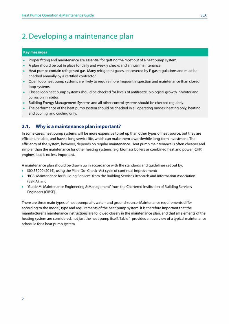
2. Developing a maintenance plan
Key messages
• Proper fitting and maintenance are essential for getting the most out of a heat pump system. • A plan should be put in place for daily and weekly checks and annual maintenance. • Heat pumps contain refrigerant gas. Many refrigerant gases are covered by F-gas regulations and must be
checked annually by a certified contractor. • Open loop heat pump systems are likely to require more frequent inspection and maintenance than closed
loop systems. • Closed loop heat pump systems should be checked for levels of antifreeze, biological growth inhibitor and
corrosion inhibitor. • Building Energy Management Systems and all other control systems should be checked regularly. • The performance of the heat pump system should be checked in all operating modes: heating only, heating
and cooling, and cooling only.
2.1. Why is a maintenance plan important? In some cases, heat pump systems will be more expensive to set up than other types of heat source, but they are efficient, reliable, and have a long service life, which can make them a worthwhile long-term investment. The efficiency of the system, however, depends on regular maintenance. Heat pump maintenance is often cheaper and simpler than the maintenance for other heating systems (e.g. biomass boilers or combined heat and power (CHP) engines) but is no less important. A maintenance plan should be drawn up in accordance with the standards and guidelines set out by: • ISO 55000 (2014), using the Plan–Do–Check–Act cycle of continual improvement; • ‘BG3: Maintenance for Building Services’ from the Building Services Research and Information Association
(BSRIA); and • ‘Guide M: Maintenance Engineering & Management’ from the Chartered Institution of Building Services
Engineers (CIBSE). There are three main types of heat pump: air-, water- and ground-source. Maintenance requirements differ according to the model, type and requirements of the heat pump system. It is therefore important that the manufacturer’s maintenance instructions are followed closely in the maintenance plan, and that all elements of the heating system are considered, not just the heat pump itself. Table 1 provides an overview of a typical maintenance schedule for a heat pump system.
Heat Pumps Operation & Maintenance Guide
3
SEAI
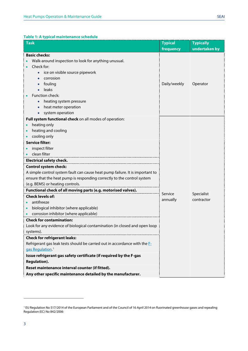
Table 1: A typical maintenance schedule Task Typical
frequency Typically undertaken by
Basic checks: • Walk-around inspection to look for anything unusual. • Check for:
• ice on visible source pipework • corrosion • fouling • leaks
• Function check: • heating system pressure • heat meter operation • system operation
Daily/weekly
Operator
Full system functional check on all modes of operation: • heating only • heating and cooling • cooling only
Service annually
Specialist contractor
Service filter: • inspect filter • clean filter
Electrical safety check. Control system check: A simple control system fault can cause heat pump failure. It is important to ensure that the heat pump is responding correctly to the control system (e.g. BEMS) or heating controls.
Functional check of all moving parts (e.g. motorised valves). Check levels of: • antifreeze • biological inhibitor (where applicable) • corrosion inhibitor (where applicable)
Check for contamination: Look for any evidence of biological contamination (in closed and open loop systems).
Check for refrigerant leaks: Refrigerant gas leak tests should be carried out in accordance with the F-gas Regulation.1
Issue refrigerant gas safety certificate (if required by the F-gas Regulation). Reset maintenance interval counter (if fitted). Any other specific maintenance detailed by the manufacturer.
1 EU Regulation No 517/2014 of the European Parliament and of the Council of 16 April 2014 on fluorinated greenhouse gases and repealing Regulation (EC) No 842/2006
Heat Pumps Operation & Maintenance Guide
4
SEAI
2.2. Staff training For a heat pump system to deliver the maximum benefits, it must be used correctly. Therefore, it is important that all relevant staff are trained in its proper care and use. Should any regulation changes occur (e.g. concerning F-gases, electrical safety, or the environment), staff should be informed immediately and, where necessary, suitable training should be provided. New staff must be trained before operating the system. It is common for buildings to use more energy than initially intended due to an oversized heating system, lack of heating controls, etc. Any alteration to the design of the building fabric, heat emitter system, heat pump system, or heat collector system, could have an impact on the overall functioning of the system. Staff must therefore be aware of any changes to the initial plan, assess how they may affect efficiency and try to mitigate the impact. For example, in a building with a heat pump system supplying underfloor heating, the building’s air infiltration rate might be higher than originally intended. The building would consequently have a higher heating requirement than planned for. In this case, the heating requirement would need to be recalculated, the system would have to be designed at a higher flow temperature and the settings for the heat pump may need to be changed. Were this issue to go unnoticed by staff (due to lack of training), the building may not heat properly. In such a scenario, a maintenance engineer would probably increase the heat pump flow temperature in an effort to increase the heat output. As a result, the heat pump would produce heat less efficiently, generating a lower Seasonal Performance Factor (SPF), higher running costs, lower carbon savings and an increased use of backup heat sources. Well-trained staff should understand the system well enough to prevent such an occurrence.
2.3. Performance snapshot When the system is up and running, a performance snapshot is taken to check that the system is as designed and working to its optimum efficiency. Ideally, this should include checks during different modes of operation: heating only; cooling only; and heating and cooling. It should also be system specific.
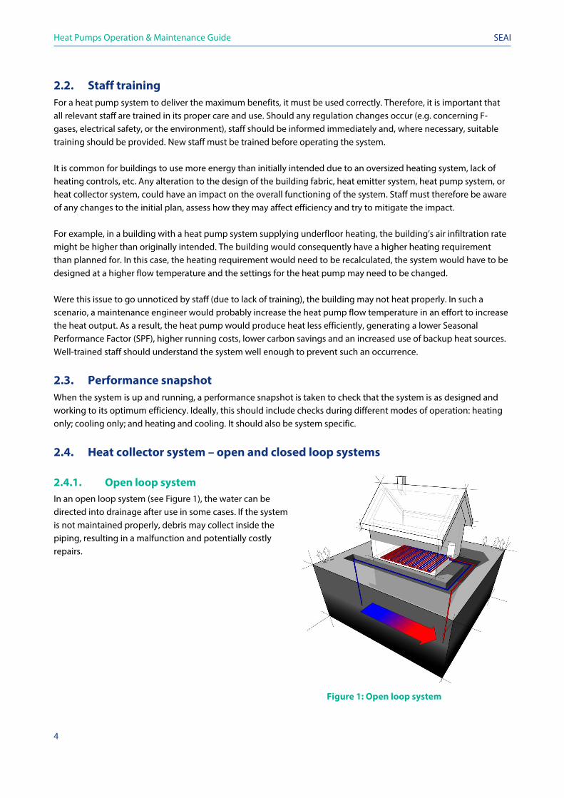
2.4. Heat collector system – open and closed loop systems 2.4.1. Open loop system In an open loop system (see Figure 1), the water can be directed into drainage after use in some cases. If the system is not maintained properly, debris may collect inside the piping, resulting in a malfunction and potentially costly repairs.
Figure 1: Open loop system
Heat Pumps Operation & Maintenance Guide
5
SEAI
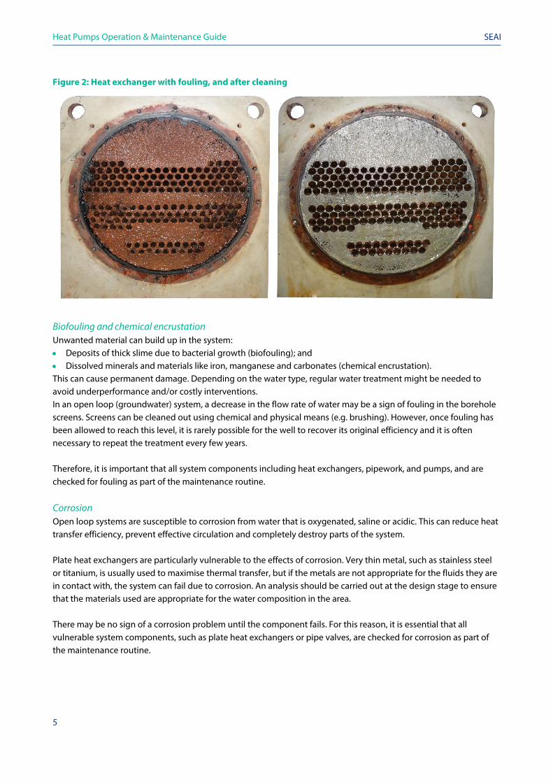
Figure 2: Heat exchanger with fouling, and after cleaning
Biofouling and chemical encrustation Unwanted material can build up in the system: • Deposits of thick slime due to bacterial growth (biofouling); and • Dissolved minerals and materials like iron, manganese and carbonates (chemical encrustation). This can cause permanent damage. Depending on the water type, regular water treatment might be needed to avoid underperformance and/or costly interventions. In an open loop (groundwater) system, a decrease in the flow rate of water may be a sign of fouling in the borehole screens. Screens can be cleaned out using chemical and physical means (e.g. brushing). However, once fouling has been allowed to reach this level, it is rarely possible for the well to recover its original efficiency and it is often necessary to repeat the treatment every few years. Therefore, it is important that all system components including heat exchangers, pipework, and pumps, and are checked for fouling as part of the maintenance routine. Corrosion Open loop systems are susceptible to corrosion from water that is oxygenated, saline or acidic. This can reduce heat transfer efficiency, prevent effective circulation and completely destroy parts of the system. Plate heat exchangers are particularly vulnerable to the effects of corrosion. Very thin metal, such as stainless steel or titanium, is usually used to maximise thermal transfer, but if the metals are not appropriate for the fluids they are in contact with, the system can fail due to corrosion. An analysis should be carried out at the design stage to ensure that the materials used are appropriate for the water composition in the area. There may be no sign of a corrosion problem until the component fails. For this reason, it is essential that all vulnerable system components, such as plate heat exchangers or pipe valves, are checked for corrosion as part of the maintenance routine.
Heat Pumps Operation & Maintenance Guide SEAI
If the composition of the water changes (e.g. the pH level), it may be necessary to replace some components with ones made from different materials or introduce other corrosion prevention measures. It is therefore important that the operator is alert to any changes in the water, and regular water quality analyses may be required.
Sand Sand in the water can cause damage to an open loop system, creating blockages and wearing out some of the system components.
If the system has not been appropriately designed, sand may enter through boreholes or poorly sealed rock fissures. Filters can be used in the building, and fine screens installed over the boreholes, to prevent the sand from entering. These maintenance strategies are preferable to pumping sand from the system, which can increase the risk of collapse or settlement and result in the borehole having to be abandoned.
Corrosion on the screening can allow sand through. This is another reason why it is important to check regularly for corrosion.
Testing of capacity For wells that are susceptible to clogging, it is recommended that a step-drawdown test is performed at intervals of between three and five years to accurately determine specific capacity, and check for any decline.
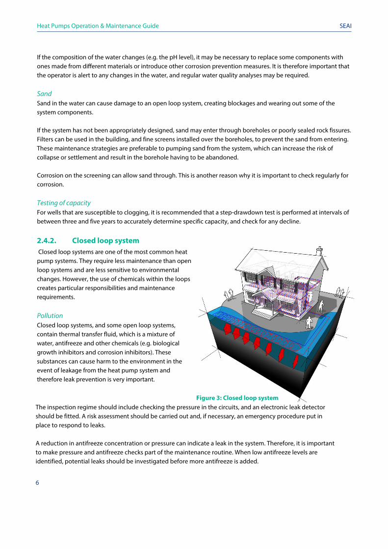
2.4.2. Closed loop system Closed loop systems are one of the most common heat pump systems. They require less maintenance than open loop systems and are less sensitive to environmental changes. However, the use of chemicals within the loops creates particular responsibilities and maintenance requirements.
Pollution Closed loop systems, and some open loop systems, contain thermal transfer fluid, which is a mixture of water, antifreeze and other chemicals (e.g. biological growth inhibitors and corrosion inhibitors). These substances can cause harm to the environment in the event of leakage from the heat pump system and therefore leak prevention is very important.
Figure 3: Closed loop system The inspection regime should include checking the pressure in the circuits, and an electronic leak detector should be fitted. A risk assessment should be carried out and, if necessary, an emergency procedure put in place to respond to leaks.
A reduction in antifreeze concentration or pressure can indicate a leak in the system. Therefore, it is important to make pressure and antifreeze checks part of the maintenance routine. When low antifreeze levels are identified, potential leaks should be investigated before more antifreeze is added.
6

Heat Pumps Operation & Maintenance Guide
7
SEAI
Antifreeze The viscosity of antifreeze is very different to that of water. If the antifreeze is not correctly mixed with water before it is added, there will be different concentration levels across the system. This can cause problems such as: • Freezing in areas with a lower concentration of antifreeze. This typically occurs in the heat pump evaporator. It is
expensive to rectify and, if not appropriately addressed, can result in the release of refrigerant gases with high global warming potential.
• Circulation problems. If undiluted antifreeze passes through the circulation pump, the flow rate may reduce due to blockages, which could result in lower temperatures in the evaporator.
• As the temperature drops, the antifreeze will become more viscous, causing a further reduction in circulation and a further drop in temperature.
• The glycol concentrate can prevent circulation entirely in some parts of the system (e.g. boreholes), resulting in the system needing to be flushed and re-filled.
This is why it is so important to follow the correct procedure when adding antifreeze to the system. A large vessel may be required for mixing the antifreeze with water. In large systems, for example, it may be necessary to pre-mix 10,000 litres or more to avoid circulation problems. Flow rates There are various factors that can cause low rates of circulation. This is why the flow rates should be checked regularly. The flow rate through the system should be checked, including, where possible, the flow rate through individual loops or boreholes. If a loop is not circulating, or there is a significant deviation from the commissioned flow rates (which should be stated in the operation and maintenance manual), this should be investigated and remedied. Clean filters All filters and screens should be cleaned as part of the maintenance regime. If there is more material being deposited than anticipated or the frequency of filters being clogged is increasing, the causes should be investigated. Material may not have been flushed out prior to commissioning. In such cases, the system should be appropriately flushed. During flushing, it is essential that the velocity of the fluid has the correct minimum value (according to BISRA guidance document BG 29/2012 Pre-Commission Cleaning of Pipework Systems). The system is often flushed before the addition of antifreeze. Submerged pipework When a closed loop system is extracting heat from a body of water (such as a river, lake or sea) through submerged pipework, the arrangements for protecting the pipework and the pipework anchor points from physical damage should be checked. Corrosion As with open loop systems, it is important to adhere to the corrosion prevention measures detailed by the manufacturer, such as chemical corrosion inhibitors or vacuum degassers. These should be checked regularly.
Heat Pumps Operation & Maintenance Guide
8
SEAI
2.5. Heat pump gases Heat pumps containing F-gases are covered by the F-gas Regulation (517/2014), and the ODS Regulation (1005/2009),2 which stipulate that certain systems using F-gases must be periodically checked for leaks. The frequency of the checks required depends on the quantity and global warming potential of the gas. It is important to incorporate these checks into the overall maintenance plan, along with the maintenance requirements set out by the manufacturer.3
2.6. Heating and cooling system It is important to check that the heat distribution system is functioning correctly, and that temperatures and flow rates are as anticipated. This should be part of the performance snapshot. The maintenance plan should include all relevant plant items, such as filters, motorised valves and pumps. Devices with moving parts are susceptible to failure and should be checked regularly.
2.7. Controls An efficient heat pump system depends on a specifically designed control system that allows the heating system to function correctly. The maintenance plan should include scheduled control system function checks. These checks are designed to make sure that the desired temperatures are being met and any necessary changes (e.g. in response to changing heat use loads or patterns) are being made. Control settings such as set points, operating times, the weather compensation curve and the switchover temperature between operating modes (in a bivalent system) should all be checked to ensure the system operates efficiently. Separate BEMS or separate process control systems should have their own maintenance regimes. The role of the heat pump system maintenance plan is to check the functioning of the heat pump system and verify that the interface between the two systems is operating correctly.
2.8. Alarms Many plant items can be linked to a system that raises an alarm when a fault occurs. These alerts are either identified by a central monitoring system or a call for manual checks. Many heat pump control systems incorporate a means of notifying the operator when necessary. Remote monitoring systems allow the system parameters to be viewed, and often make it possible to change the settings. Any event that triggers an alarm should be recorded and investigated. Problems such as a blocked filter, for example, or a broken motorised valve, take time to clean or replace. Although it may not always be possible to rectify the problem immediately, the alarm log should nonetheless be checked as part of the maintenance plan, to determine if additional remedial action is required. Heat pumps often have high- and low-pressure alarms. These notify the user if the pressure in the refrigerant circuit is too low (e.g. the source is too cold) or too high (e.g. the heating system is too hot). High or low pressure are often symptoms of a problem with one of the components. For example, a low-pressure alarm in a ground-source heat pump may be caused by the growth of the bacteria Pseudomonas impeding the circulation in an evaporator.
2 ODS Regulation 1005/2009 of the European Parliament and of the Council of 16 September 2009 on substances that deplete the ozone layer 3 EPA, 2015, Complying with Regulations Controlling Fluorinated Greenhouse Gases and Ozone Depleting Substances: A Guidance Note for Operators of Equipment Containing F-gases and ODS
Heat Pumps Operation & Maintenance Guide
9
SEAI
A high-pressure alarm could be triggered by a lack of flow through the condenser as a consequence of a faulty motorised valve.
2.9. Maintenance logs Changes made to the heat distribution system can affect the performance of the heat pump. Therefore, it is important to record not only the maintenance work carried out on the heat pump system, but also repair or improvement work on any of the systems on which it depends. These logs should be consulted as part of the maintenance plan, to ensure that all issues have been fully resolved and check if the system has been affected by remedial work. The heat distribution system may be maintained by a company that offers a specific maintenance package for heat pumps. A heat pump installation can also be an energy service company (ESCO). An ESCO is a firm that offers to reduce the client’s energy bill, and split the cost savings with them. Traditionally, ESCOs offer finance for their projects, will accept the risk of the project and are remunerated in proportion to the savings achieved. In both a maintenance and ESCO contractual arrangement, the heat pump operator should be notified of any planned changes so that any potential effects on the performance of the heat pump can be identified and addressed.
Heat Pumps Operation & Maintenance Guide
10
SEAI
3. Verify performance using a monitoring system
Key messages
• A monitoring system can be used to verify performance, alert operators to problems and identify solutions. • The seasonal performance factor can be calculated using a heat meter and an electricity meter (see Section
3.3.). • A heat meter can be used to provide further insight into the operation of the system. Using heat meters at both
the source and the output can provide an accurate picture of the performance of the heat pump and the systems on which it depends.
• Correct placement of electricity meters is important to ensure that only the electricity consumed by the heat pump and, if required, the associated plant, are being recorded.
• A system for recording the data is required. Larger operations require a supervisory control and data acquisition system.
• The seasonal performance factor and the heat delivered need to be compared with the design criteria. Where there is a significant difference, the potential consequences and appropriate actions must be identified. For example, if a ground loop system is providing more heat than it is designed to, additional capacity may be required, or the heat output should be capped to prevent ground temperatures from falling too low.
• F-gas regulations may require constant monitoring for leaks and annual checks by a certified contractor.
Once the system is in operation, it is important to monitor its performance to ensure that it is providing the benefits anticipated at the design and planning stage. It is essential to regularly measure the amount of heat produced by the system and the amount of electricity required to run it.
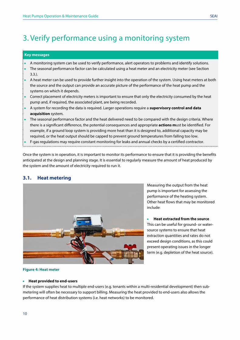
3.1. Heat metering Measuring the output from the heat pump is important for assessing the performance of the heating system. Other heat flows that may be monitored include: • Heat extracted from the source This can be useful for ground- or water-source systems to ensure that heat extraction quantities and rates do not exceed design conditions, as this could present operating issues in the longer term (e.g. depletion of the heat source).
Figure 4: Heat meter • Heat provided to end-users If the system supplies heat to multiple end-users (e.g. tenants within a multi-residential development) then sub-metering will often be necessary to support billing. Measuring the heat provided to end-users also allows the performance of heat distribution systems (i.e. heat networks) to be monitored.
Heat Pumps Operation & Maintenance Guide
11
SEAI
Dedicated heat meter units (see Figure 4) may be used to measure heat output. These typically comprise: • A flow sensor, measuring the flow rate of heat transfer fluid through the system; • Two sensors measuring the temperature of the heat transfer fluid before and after the heat source; and • A digital calculator unit that combines data from the above sensors with pre-programmed data on the thermal
properties of the heat transfer fluid to determine the amount of heat added to, or removed from, the fluid. Many meters incorporate data loggers that store readings. Others can be fitted with monitors that allow readings to be stored on an external data system. Trends in heat use can be examined using this data. This assists with fault finding and problem resolution. Examples of how heat monitoring can help identify faults include: • If return temperatures are higher than expected at times when the heat pump is not in operation, this may
indicate that a backup heat source has been activated; and • A higher or lower temperature difference than expected across the heat pump system may indicate that a
circulation pump is set at the wrong flow rate. More information on heat meters is provided in the accompanying Technology Guide.
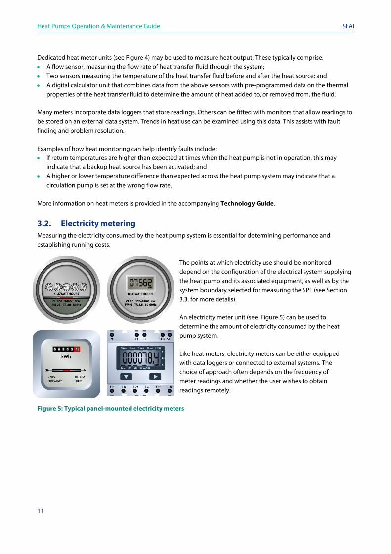
3.2. Electricity metering Measuring the electricity consumed by the heat pump system is essential for determining performance and establishing running costs.
The points at which electricity use should be monitored depend on the configuration of the electrical system supplying the heat pump and its associated equipment, as well as by the system boundary selected for measuring the SPF (see Section 3.3. for more details). An electricity meter unit (see Figure 5) can be used to determine the amount of electricity consumed by the heat pump system. Like heat meters, electricity meters can be either equipped with data loggers or connected to external systems. The choice of approach often depends on the frequency of meter readings and whether the user wishes to obtain readings remotely.
Figure 5: Typical panel-mounted electricity meters
Heat Pumps Operation & Maintenance Guide
12
SEAI
3.3. Verification of efficiency The principal metric used for measuring the performance of a heat pump system is the SPF. It is defined as follows:
𝑆𝑆𝑆𝑆𝑆𝑆𝑆𝑆𝑆𝑆𝑆𝑆𝑆𝑆𝑆𝑆 𝑝𝑝𝑆𝑆𝑝𝑝𝑝𝑝𝑆𝑆𝑝𝑝𝑝𝑝𝑆𝑆𝑆𝑆𝑝𝑝𝑆𝑆 𝑝𝑝𝑆𝑆𝑝𝑝𝑓𝑓𝑆𝑆𝑝𝑝 =𝑇𝑇𝑆𝑆𝑓𝑓𝑆𝑆𝑆𝑆 ℎ𝑆𝑆𝑆𝑆𝑓𝑓 𝑆𝑆𝑆𝑆𝑆𝑆𝑝𝑝𝑒𝑒𝑒𝑒 𝑆𝑆𝑜𝑜𝑓𝑓𝑝𝑝𝑜𝑜𝑓𝑓 𝑝𝑝𝑆𝑆𝑝𝑝 𝑆𝑆𝑆𝑆𝑆𝑆𝑜𝑜𝑝𝑝 (𝑘𝑘𝑘𝑘ℎ)𝑇𝑇𝑆𝑆𝑓𝑓𝑆𝑆𝑆𝑆 𝑆𝑆𝑆𝑆𝑆𝑆𝑝𝑝𝑓𝑓𝑝𝑝𝑒𝑒𝑝𝑝𝑒𝑒𝑓𝑓𝑒𝑒 𝑒𝑒𝑆𝑆𝑝𝑝𝑜𝑜𝑓𝑓 𝑝𝑝𝑆𝑆𝑝𝑝 𝑆𝑆𝑆𝑆𝑆𝑆𝑜𝑜𝑝𝑝 (𝑘𝑘𝑘𝑘ℎ)
If a building has a heat pump supplying 100,000 kWh of heat, and uses 25,000 kWh of electricity, the SPF will be 4.
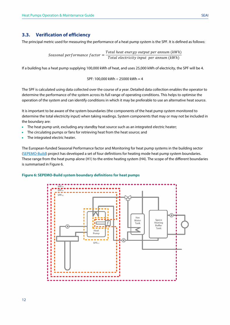
SPF: 100,000 kWh ÷ 25000 kWh = 4 The SPF is calculated using data collected over the course of a year. Detailed data collection enables the operator to determine the performance of the system across its full range of operating conditions. This helps to optimise the operation of the system and can identify conditions in which it may be preferable to use an alternative heat source. It is important to be aware of the system boundaries (the components of the heat pump system monitored to determine the total electricity input) when taking readings. System components that may or may not be included in the boundary are: • The heat pump unit, excluding any standby heat source such as an integrated electric heater; • The circulating pumps or fans for retrieving heat from the heat source; and • The integrated electric heater. The European-funded Seasonal Performance factor and Monitoring for heat pump systems in the building sector (SEPEMO-Build) project has developed a set of four definitions for heating mode heat pump system boundaries. These range from the heat pump alone (H1) to the entire heating system (H4). The scope of the different boundaries is summarised in Figure 6. Figure 6: SEPEMO-Build system boundary definitions for heat pumps
Heat Pumps Operation & Maintenance Guide
13
SEAI
When comparing the performance of different heat pump systems or tracking the performance of a heat pump system over time, it is important to ensure that the system boundaries stay the same. The choice of boundary depends on the configuration of an individual installation. Some heat pump control systems supply power to circulation pumps and backup electric heaters. In this case, a single electricity meter recording the amount of electricity supplied to the heat pump will automatically necessitate SPFH4 (in Figure 6) to be the boundary. In other systems, the components are distributed between different plant rooms or even different buildings, in which case SPFH2 may be the appropriate choice of boundary definition. It is important to understand the boundaries of the area and how the meter recording works, particularly if the SPF is to be reported for regulatory purposes or for an incentive scheme.
3.4. Comparison with design conditions There are several parameters to be regularly monitored and compared to design conditions. These include: • Heat source flow and return temperatures, and total heat extracted Monitoring these parameters verifies whether the rate of heat extraction matches the design rate. Exceeding the planned heat extraction rate might cause the heat source to deplete over time. If the flow temperature is lower than the design values for extended periods of time, this may cause problems, such as system fluids freezing. • Heat distribution system flow and return temperatures, and total heat provided This data can indicate if the system is operating in line with design conditions. An imbalance in the system can indicate an issue with the system set-up and lead to fluctuating temperatures in different zones/spaces. • Peak heat use and heat use profile Monitoring the pattern of heat demand enables the user to determine if the system is operating as intended. If peak or overall use is greater than it should be, then this might indicate the need to modify system settings or add capacity to the system. When discrepancies are found in these areas, further investigations may be required and remedial action should be taken. For example, in a building where the heat pump provides space heating only, room temperature probes can log the temperatures achieved and they can be compared to design conditions. This reveals if the building is being heated to a higher temperature than planned. It may be that the controls are set to a higher temperature, or the control system is not performing as required. The appropriate changes to the controls and/or to the heat distribution system required to address this can be calculated. When it is not possible to reach room temperatures in this way, or the control system is functioning correctly but a temperature above what can be met is required, it may be necessary to investigate ways of either increasing the capacity of the heat pump system, or limiting the use of the heat pump to the design scope.
3.5. F-gas responsibilities Most heat pumps use hydrofluorocarbons (HFCs), which are classed as an F-gas. F-gases can only be used in line with certain regulations. It is the responsibility of operators to keep up to date and comply with F-gas regulations. They must ensure that the system never releases these gases, and that it is disposed of correctly at the end of its life.
Heat Pumps Operation & Maintenance Guide
14
SEAI
The operator’s obligations include: • Determining if their equipment contains an F-gas or ozone depleting substance (ODS) regulated by the
EU. A full list of F-gases is provided in European Regulation No 517/2014 and includes HFC 404A and HFC 410A, both of which are commonly used in heat pump systems.
• Using appropriately trained technicians to install and maintain systems containing F-gases. A list of F-gas
certified contractors is available from F-Gas Registration Ltd. • Labelling equipment that contains F-gases and providing relevant information. Necessary information
includes the mass of gas in the equipment (in kg) and the global warming potential of the gas in question. • Checking for leaks at regular intervals. The maximum interval between leak checks will depend on the global
warming potential of the F-gas being used, and the amount of gas in the system. Typical intervals will be between three months and a year. Exceptions exist for systems that are ‘hermetically sealed’. Intervals can also be longer if a leak detector has been installed. If a leak is detected, then it must be repaired and the system rechecked within a month.
• Installing leak detection equipment. For systems containing quantities of F-gases that are equivalent to more
than 500 tonnes of carbon dioxide (CO2), the operator is required to install an automatic leak detection system. The system must be checked once a year to ensure it is working properly.
The CO2 equivalent of an F-gas is calculated by multiplying its mass in tonnes by its global warming potential. The quantity of F-gas that is equivalent to 500 tonnes of CO2 can be determined by dividing 500 by the global warming potential of the F-gas. In the case of HFC 404A (global warming potential 3,922), this would be 500 divided by 3,922, which is 0.126 tonnes (126kg) of HFC 404A. The global warming potentials of common refrigerants are given in Appendix 5 of the Environmental Protection Agency (EPA) guidance on complying with F-gas regulations. Keeping records Where the system is subject to mandatory leak checks, the following records must be kept:
• Quantity and type of F-gas held in the system; • Quantity and type of any F-gas added during maintenance; • Details of companies that have worked on the system, including, where applicable, their certificate
number (e.g. installer, maintenance contractor and decommissioning contractor); • Dates and results of all mandatory leak checks; and • Measures taken to recover and dispose of F-gases at the end of a system’s life (e.g. disposal through a
registered waste carrier). These records must be kept for five years and provided to the relevant authorities on request. Further information can be found in the EPA guidance for operators of equipment containing ODS and F-gases. You should install an automatic leak detector even when it is not mandatory. Identifying leaks early can prevent damage to the system. It can also avoid human exposure to gases that may pose a health and safety risk under certain circumstances (e.g. ammonia, which can be flammable).
Heat Pumps Operation & Maintenance Guide
15
SEAI
4. Record keeping It is the responsibility of the operator to develop and maintain adequate documentation that records all relevant information, from the handover of the plant through to its decommissioning. This is vital to ensuring that the equipment is operated and maintained in a safe and effective manner.
4.1. Handover documentation The installer should provide an operations and maintenance (O&M) file at the handover. Both a hard copy and an electronic copy of the file must be supplied. It must include: • Drawings and schematics showing how the plant has been installed, • Commissioning records documenting all checks and procedures carried out to date, • Certificates of conformity for the equipment • A list of all equipment, referencing compliance with the corresponding European product safety directives, • Procedures for operating and maintaining the plant, • The manufacturer’s full instructions, along with the corresponding legislative requirements and good practice
recommendations, • Details of any routine maintenance checks that need to be performed, and • Details of spare/replacement parts, including, where needed, a recommended spare parts holding list. Both hard copies and electronic copies of the file should be held on site for ease of access. This also enables records to be updated as necessary.
4.2. During operating life Records must be kept throughout the operating life of the plant so that evidence of proper maintenance can be shown. Examples of appropriate records include: • Updating drawings/schematics to reflect any amendments made to the system. This is necessary to help
with maintenance, fault identification and resolution. • Maintenance records. Records should cover planned and unplanned maintenance and range from electronic
planned preventive maintenance systems to on-site log books. This includes any records provided by contractors following service events (e.g. site visit reports).
• Meter records. This is to support performance monitoring (see Section 3.). The operator must ensure that the
meter data is accurate, particularly where records form the basis of billing, formal environmental reporting or incentives claims. Measures must be taken to avoid errors. Automated meter readings are a good way to ensure accuracy. In the case of manual readings, evidence such as date-stamped photographs should be kept to substantiate any data.
• Compliance records. These records should demonstrate that the operator has complied with all regulatory
requirements, including: • Recalibration and/or replacement records for meters, • F-gas Regulation records (see Section 3.5.), and • Environmental monitoring (e.g. water samples, calibration of monitoring equipment, records of
sample analyses and any surveys undertaken).

Heat Pumps Operation & Maintenance Guide
16
SEAI
4.3. End of life After the operating life of the plant, the operator should keep records demonstrating that the equipment has been decommissioned and disposed of in an appropriate manner. This includes evidence that the equipment has been sent to a competent party for the purposes of reuse, recycling or disposal. This is particularly important when the equipment falls under the F-gas Regulation (see Section 3.5.).
Heat Pumps Operation & Maintenance Guide
17
SEAI
5. Reporting The operator must be aware of their obligation to report notifiable incidents. Formal reporting processes must be put in place, and the task should be allocated to suitable staff members trained to know what, when, and to whom they need to report.
5.1. Environmental reporting There are various circumstances under which environmental reporting is obligatory. Reporting will normally be required either on a regular basis or in the event of an incident. Under F-gas regulations, a competent authority must be notified should refrigerant gas be released. Depending on the type of heat pump system, there may be requirements for monitoring and reporting the temperature of water discharged into a watercourse, or for reporting any thermal transfer fluid that may enter land or a watercourse.
5.2. Internal/contractual reporting A heat pump installation often results in a reduction in CO2 emissions, and it may be necessary to report the amount of renewable energy extracted or carbon saved. The system of record keeping and reporting must reflect any internal targets or those that are contractually obliged. A system that is part of an ESCO arrangement or similar, is likely to come with reporting requirements such as: • Total heat delivered • Total electricity consumed • Seasonal performance factor • Carbon footprint and intensity of heat delivered Government financial incentive schemes may have other requirements for reporting, and these must be identified and planned for.
Heat Pumps Operation & Maintenance Guide
18
SEAI
6. Health and safety
Key messages
• Risks associated with the heat pump system need to be identified, considered and mitigated. • Refrigerator gasses carry various health and safety risks. From the outset, operators must know which gases are
being used, and educate themselves on the particular risks. • Some refrigerants are explosive (e.g. propane) or toxic (e.g. ammonia) and should only be used by those
suitably qualified to do so. • Legionella is a health and safety risk of any hot or cold water distribution system. There is a particularly high risk
if the heat pump cannot heat water to 60 °C, and an additional heat source, such as an immersion heater, may be required.
Safety issues can arise from activities such as installation, servicing and operation, and the use of equipment on a building. The first step towards ensuring a healthy and safe workplace is to develop a risk assessment. Guidance on preparing risk assessments and safety statements can be found on the Health & Safety Authority (HSE) website. The risk assessment should be regularly reviewed and made available to relevant personnel and management. All relevant staff should be invited to contribute to the development of the risk assessment. Should any incidents or near misses occur, then the events leading up to them should be investigated. The risks identified should be recorded in the assessment alongside any mitigating actions taken. There is an international standard for health and safety, known as ISO 18001 (or ISO 45001), which can be used as a guide.
6.1. Health and safety regulations While the purpose of good safety practices is to prevent injury, it is also important to note that failure to follow safety regulations can lead to prosecution. Regulations are in place to ensure that proper risk assessments are in place and adhered to, and that safety requirements such as staff training and providing personal protective equipment (PPE) are respected. In Ireland, the main legislation is the Safety, Health and Welfare at Work Act 2005. When chemicals or hazardous substances are involved, then the Control of Substances Hazardous to Health (COSHH) regulations apply. Under these regulations, employers need to either prevent or reduce their workers' exposure to hazardous substances. The release of dangerous chemicals from heat pumps into the atmosphere can cause fire, explosion, and/or toxicity. There are various regulations on these at European level, which are implemented in Ireland by SI No. 299 of 2007: Safety, Health and Welfare at Work (General Application) Regulations 2007. More information on explosive atmospheres can be found in the Guide to the Safety, Health and Welfare at Work (General Application) Regulations 2007 Part 8: Explosive Atmospheres at Places of Work.
Heat Pumps Operation & Maintenance Guide
19
SEAI
6.2. Areas of potential risk When all of the installation, commissioning, operation and maintenance of the heat pump system is contracted to specialist providers, the contractor should also take responsibility for safety. In such cases, the role of the building/facility owner is to work with the service provider to ensure that an adequate risk assessment is undertaken and safety statements are developed. The host must then ensure that the appropriate staff on site are aware of these documents, read them and adhere to them. For instance, these statements may specifically preclude local staff from entering certain areas or touching certain equipment. When only some (or none) of the installation, operation or maintenance activities of the heat pump are contracted out, then each element under the responsibility of the host site will need its own risk assessments and safety statements. The sections below highlight the areas that might fall into this category
6.2.1. Electrical The Health and Safety Authority (HSA) provides a list of potential risks associated with electricity in the workplace, available at the HSE website and the HSE electrical safety guide for employers. Any electrical installation, maintenance or repair work must be undertaken by a suitably qualified electrician. All electrical installations must comply with the National Rules for Electrical Installations.
6.2.2. Refrigerant leakage All refrigeration systems are at risk of gas leakage. Operators must be aware of the specific risks associated with the gases used in their heat pump system and how to mitigate them. The risks presented by refrigerator gases include explosion, toxicity, air displacement, and cold burns. It is important that operation and maintenance staff follow all the recommended measures to reduce the possibility of leaks. This usually means avoiding any damage to pipework, ensuring the proper management of cylinders, and taking the necessary precautions during recharging. Leak detectors for the refrigerant in question should be used. It is good practice to fit these at suitable points (and as specified by the detector manufacturer). 6.2.2.1. Confined spaces – suffocation risk Working with gases other than air in an enclosed space always presents the risk of suffocation and death. Danger signs that staff should be made aware of include feeling unwell, dizziness and falling over. Working on a heat pump in a confined space requires preparation and adequate ventilation (ideally, never work alone in a confined space). More information on safety in confined spaces is available at the HSE website. 6.2.2.2. Explosive gases It is important that staff operating or maintaining the equipment are made aware of any flammable gases (e.g. ammonia). Naked flames should be avoided in the area, workers should be aware of any potential leaks, and the principles of the Dangerous Substances and Explosive Atmospheres Regulations 2002 (DSEAR) must be adhered to at all times.
Heat Pumps Operation & Maintenance Guide
20
SEAI
6.2.2.3. High-pressure systems Highly pressurised CO2 is central to the workings of a transcritical heat pump. This is why it is essential that anyone working with these systems complies with the regulations governing pressure systems published by the HSE. The maintenance of transcritical systems is likely to require specialist contractors who are familiar with working with high-pressure systems. 6.2.2.4. Rapid expansion – risk of freezing Another risk associated with refrigerants is rapid expansion leading to localised freezing, which can cause burns. Such events are normally the result of damage to the plant. While proper care should minimise this risk, all workers who could be affected should be made aware of this potential hazard and how to deal with it. Precautions include wearing safety goggles and gloves when handling refrigerants and servicing the refrigeration system. 6.2.2.5. Toxicity Some refrigerants, in particular ammonia, can cause fatal respiratory problems. Even low concentrations can lead to severe eye irritation. Any risk of ammonia being released should be identified and mitigating action should be taken. Large-scale systems often contain ammonia, and it has long been used in industrial refrigeration. Measures to mitigate these risks are likely to include: extraction and ventilation; vapour detectors to activate alarms and emergency extraction; procedures to ensure that there are always at least two people working (second person to help in an emergency); and appropriate staff training.
6.3. Legionella Any hot- or cold-water system is a potential source of Legionella, a bacterial growth that can cause fatalities. The accompanying SEAI Heat Pump Technology Guide discusses design solutions to mitigate the risk of Legionella. When the risks cannot be sufficiently mitigated by design measures alone, there may be operation and maintenance requirements. These may include actions such as flushing ‘dead legs’ (a length of pipe that water doesn't move through) in hot water distribution systems at an agreed frequency.
6.4. Fire Consideration should be given to what might happen to the installation if there was a fire at the facility, especially if it is a high-pressure system or one that contains flammable refrigerant. Suitable warning notices must be displayed, and the local fire service should be advised of the hazard where appropriate.
6.5. Water-source systems – suction risk There is a particular risk from heat pumps that draw water from a body of water. The suction required to take up the water can cause danger near the point of entry, even if it is guarded with a mesh. The disturbance to the water can be a problem for people using the water in the vicinity of the entry and exit points. The system developer is required to consider and mitigate these effects.
Heat Pumps Operation & Maintenance Guide
21
SEAI
7. Environmental issues There are a number of environmental issues that need to be managed during the lifetime of a heat pump system. Some of these arise at the installation and commissioning stages, and others during the operation phase. An assessment must be made of all environmental issues for a specific system on a specific site, including legal obligations.
7.1. ISO 14001 ISO 14001 is the international standard that specifies requirements for an effective environmental management system (EMS) and can help organisations identify, manage and control activities that have an environmental impact.
7.2. Temperature of watercourses The temperature at which water is discharged from an open loop system can be lower than the temperature of the watercourse, or higher when cooling is provided. This can have an impact on flora and fauna in the watercourse (e.g. a change in temperature could lead to algae growth). In view of this, appropriate limits on the temperature reduction or increase should be agreed at the outset. The temperature of the water being discharged should be monitored to ensure that any agreed limit on the temperature difference, or an absolute minimum/maximum temperature, is adhered to. In open loop collector systems, a change in temperature can lead to algae growth. Closed loop collector systems in ponds, rivers or lakes can freeze if too much heat is removed. It is important to monitor the temperatures in a closed loop system and to ensure that it does not freeze due to the heat pump operating outside of design conditions. There may also be minimum temperatures, agreed with the EPA for example, as a condition for permission to use the system.
7.3. F-gas Regulation Many refrigerant gases are F-gases with a high global warming potential, such as R407c, R134a and R410. These are covered by the F-gas Regulation. The release of gases with a high global warming potential (e.g. through leaks) can be detrimental to the overall carbon emissions reduction from operating the heat pump system. There are alternative refrigerant gases with lower global warming potentials. These may be appropriate for use in the heat pump system. Specifying a heat pump that uses one of these gases should be considered at the design or plant replacement stage. The European Union has implemented a series of regulations to phase out the use of certain F-gases and encourage the use of gases with a lower environmental impact. The F-gas Regulation: • Limits the total amount of F-gases that can be sold in the EU and is phasing them down to one-fifth of 2014 sales
by 2030; • Bans the use of F-gases in many new types of equipment when less harmful alternatives are widely available;
and • Prevents emissions of F-gases from existing equipment by requiring checks, proper servicing and recovery of the
gases at the end of the equipment's life. There are low or zero global warming potential alternatives that can be specified at the design stage, such as CO2 (R744) and ammonia (R717), and emerging refrigerants, such as HFO-1234yf and HFO-1234z, that can act as direct replacements for existing refrigerants.
Heat Pumps Operation & Maintenance Guide
22
SEAI
In Ireland, the F-gas Regulation and the ODS Regulation are implemented and enforced by the EPA. The EPA has produced guidance documents to provide clarification and assistance to contractors and end-users on refrigeration and air-conditioning equipment, and on how the legislation applies to them. The EPA also carries out inspections of premises to ensure compliance. Owners and operators of heat pumps are required to comply with the regulations. The requirements vary with the size and type of system and include well-kept records and regular leak checks.
7.4. Thermal transfer fluid leakage The thermal transfer fluid used in closed loop collector systems is most often based on either ethylene glycol or propylene glycol with other additives. While ethylene glycol is more toxic than propylene glycol, both pose dangers. It is important to avoid the discharge of chemicals like these into watercourses, groundwater or surface water. As discussed in Section 5.1., a monitoring system can be used to detect leaks early and prevent any unintended release of refrigerant. However, the storage of such chemicals on site and the procedures for handling them and dosing the system should be designed to minimise the chance of leaks.
7.5. Silt When works are being undertaken in or adjacent to rivers, including borehole drilling, there is a risk that silt can be disturbed in the watercourse or washed into it. This can de-oxygenate the water and result in the destruction of the habitats of fish and other fauna. Care must be taken to ensure that runoff water from the site works is not able to reach watercourses.
7.6. Contaminated land When land is contaminated, there is a risk that digging boreholes or horizontal trenches to install a system could allow the contamination to enter groundwater or surface water. More information on these risks is available on the EPA website.

Sustainable Energy Authority of IrelandThree Park PlaceHatch Street UpperDublin 2IrelandD02 FX65
e [email protected] www.seai.iet +353 1 808 2100
@seai_ie