Embed Size (px)
Citation preview

11
Heat-Pipe-Cooled LeadingEdges for Hypersonic
Vehicles
Workshop on Materials and Structures forHypersonic Flight
University of California Santa BarbaraJuly 12-13, 2006
David E. GlassNASA Falcon Lead
NASA Langley Research [email protected]

22
Agenda
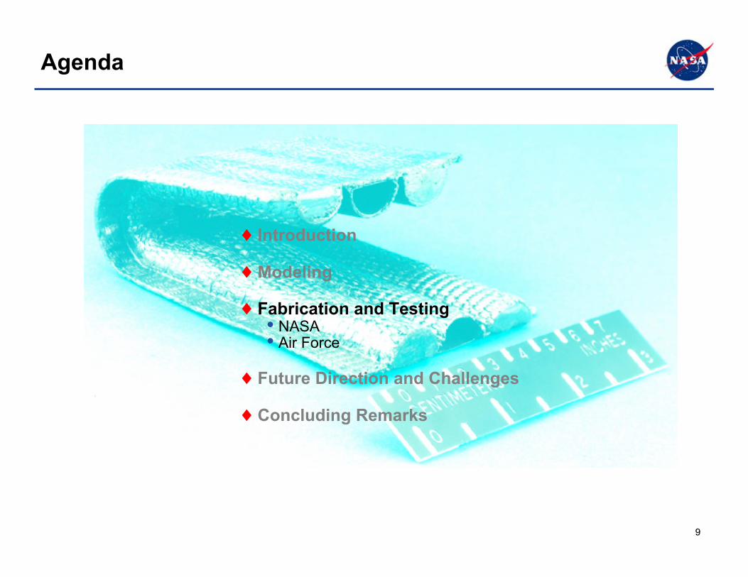
♦ Introduction
♦Modeling
♦Fabrication and Testing
♦Future Direction and Challenges
♦Concluding Remarks

33
♦ Heat pipes transfer heat isothermally by theevaporation and condensation of a working fluid.
Heat-Pipe Operation

44
Leading-Edge Heat-Pipe Operation
0
25
50
75
100
Heat flux,Btu/ft2-sec
-40 -30 -20 -10 0 10 20 30 40
Position, in.
Uppersurface
Lowersurface
NASP ascent(qmax = 495 Btu/ft2-sec)
ShuttleOrbiter
Sharp LE,hypersonic vehicle
55
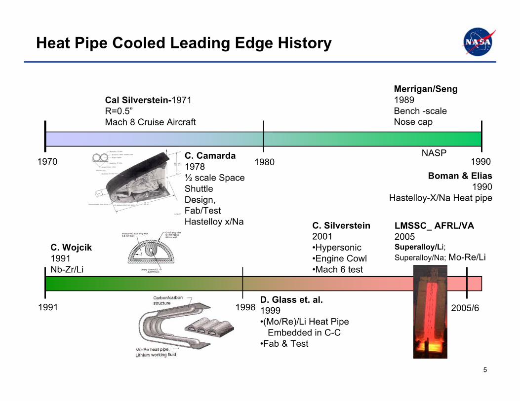
Heat Pipe Cooled Leading Edge History
1970 1990
1991D. Glass et. al.1999•(Mo/Re)/Li Heat Pipe Embedded in C-C•Fab & Test
C. Silverstein2001•Hypersonic •Engine Cowl•Mach 6 test
Cal Silverstein-1971R=0.5”Mach 8 Cruise Aircraft
C. Camarda1978½ scale SpaceShuttleDesign,Fab/TestHastelloy x/Na
NASP
Merrigan/Seng1989Bench -scaleNose cap
Boman & Elias1990
Hastelloy-X/Na Heat pipe
1980
2005/6
C. Wojcik1991Nb-Zr/Li
1998
LMSSC_ AFRL/VA2005Superalloy/Li;Superalloy/Na; Mo-Re/Li

66
Agenda
♦ Introduction
♦ Modeling
♦ Fabrication and Testing
♦ Future Direction and Challenges
♦ Concluding Remarks
77
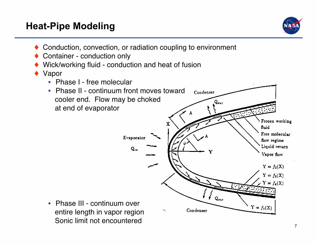
Heat-Pipe Modeling
♦ Conduction, convection, or radiation coupling to environment♦ Container - conduction only♦ Wick/working fluid - conduction and heat of fusion♦ Vapor
• Phase I - free molecular• Phase II - continuum front moves toward
cooler end. Flow may be choked at end of evaporator
• Phase III - continuum over entire length in vapor region Sonic limit not encountered

88
Heat-Pipe-Cooled Leading Edge Finite Element Analysis
Tmax
3-D finite element model(non linear properties)
Tmax = 2765°F
Thp = 2197°F
2765272626872648260925702531249224532415237623372298225922202181
°F
99
Agenda
♦ Introduction
♦ Modeling
♦ Fabrication and Testing• NASA• Air Force
♦ Future Direction and Challenges
♦ Concluding Remarks

1010
NASA Langley Heat-Pipe Leading-Edge Experience
• Shuttle - Hastelloy-X - Na working fluid - Circular heat pipes
• Advanced STS - Hastelloy-X - Na working fluid - Rectangular heat pipes
• NASP - Mo-Re embedded in C/C - Li working fluid - D-shaped heat pipes
• Experience in design, analysis, integration, and testing

1111
NASP Carbon/Carbon Heat-Pipe-CooledWing Leading Edge
Refractory composite structure
Mo-Re heat pipeLithium working fluid
Heat pipes passively reduceleading-edge temperatures to reuse limits of composite
1212
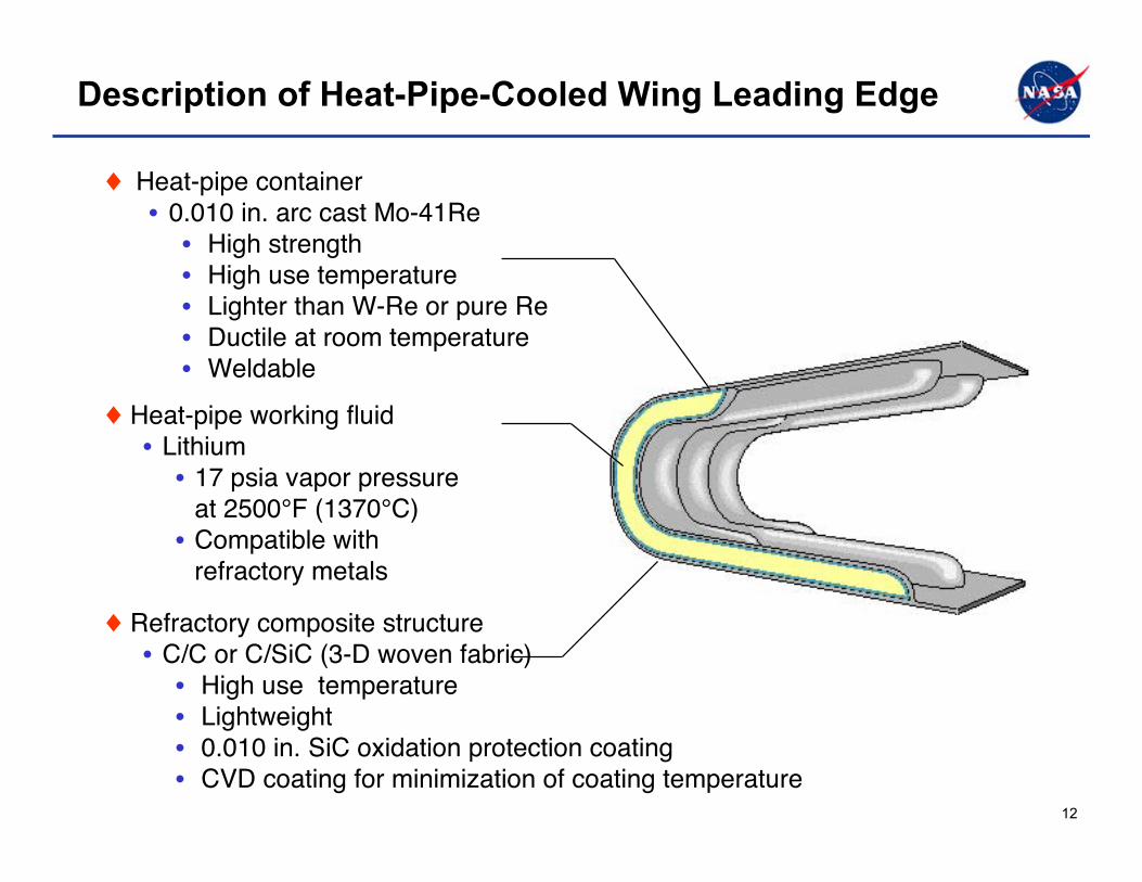
Description of Heat-Pipe-Cooled Wing Leading Edge
♦ Refractory composite structure• C/C or C/SiC (3-D woven fabric)• High use temperature• Lightweight• 0.010 in. SiC oxidation protection coating• CVD coating for minimization of coating temperature
♦ Heat-pipe working fluid• Lithium• 17 psia vapor pressure
at 2500°F (1370°C)• Compatible with
refractory metals
♦ Heat-pipe container• 0.010 in. arc cast Mo-41Re• High strength • High use temperature• Lighter than W-Re or pure Re• Ductile at room temperature• Weldable
1313
Heat-Pipe-Cooled Leading Edge Development
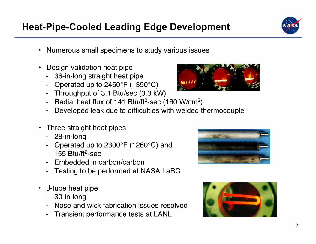
• Numerous small specimens to study various issues
• Design validation heat pipe - 36-in-long straight heat pipe - Operated up to 2460°F (1350°C) - Throughput of 3.1 Btu/sec (3.3 kW) - Radial heat flux of 141 Btu/ft2-sec (160 W/cm2) - Developed leak due to difficulties with welded thermocouple
• Three straight heat pipes - 28-in-long - Operated up to 2300°F (1260°C) and 155 Btu/ft2-sec - Embedded in carbon/carbon - Testing to be performed at NASA LaRC
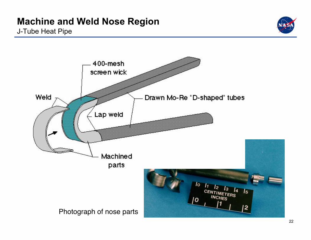
• J-tube heat pipe - 30-in-long - Nose and wick fabrication issues resolved - Transient performance tests at LANL

1414
Heat-Pipe Fabrication and TestingDesign Validation Heat Pipe
• Container: 0.01-in. arc cast Mo-41Re, 0.3-in. radius• Wick: 4 layers of 400 x 400 Mo-5Re screen
• Artery to reduce liquid pressure drop - 0.1-in. diameter, 400 x 400 mesh screen - Located on non-heated surface - Spring in artery for support - One end closed, pool at other end
• Heat pipe with thermocouples and induction heat coils

1515
Steady State Heat-Pipe Operation Design Validation Heat Pipe
Note: Thermocouples ~ 4 in. apart.
0
400
800
1200
1600
2000
2400
2800
Temp, °F
0 4 8 12 16 20 24 28 32 36
Position, in.
Q = 3.1 Btu/s
Q = 0.38 Btu/s
Q = 0.38 Btu/s
q

1616
Heat-Pipe Start-Up From the Frozen StateDesign Validation Heat Pipe
(~ 4-in. spacing)
0
500
1000
1500
2000
Temp., °F
0 500 1000 1500 2000
Time, sec.
TC 1 TC 2
TC 5
TC 6
TC 3
TC 10
TC 7
TC 8
TC 9
TC #1 TC #2 TC #5TC #3• • • •• Heat pipe
Induction heating
1717
Heat-Pipe-Cooled Leading Edge Development
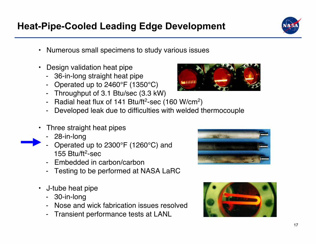
• Numerous small specimens to study various issues
• Design validation heat pipe - 36-in-long straight heat pipe - Operated up to 2460°F (1350°C) - Throughput of 3.1 Btu/sec (3.3 kW) - Radial heat flux of 141 Btu/ft2-sec (160 W/cm2) - Developed leak due to difficulties with welded thermocouple
• Three straight heat pipes - 28-in-long - Operated up to 2300°F (1260°C) and 155 Btu/ft2-sec - Embedded in carbon/carbon - Testing to be performed at NASA LaRC
• J-tube heat pipe - 30-in-long - Nose and wick fabrication issues resolved - Transient performance tests at LANL
1818
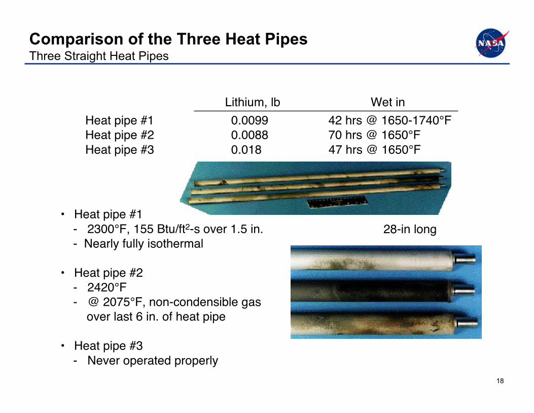
Comparison of the Three Heat PipesThree Straight Heat Pipes
Heat pipe #1 0.0099 42 hrs @ 1650-1740°FHeat pipe #2 0.0088 70 hrs @ 1650°FHeat pipe #3 0.018 47 hrs @ 1650°F
Lithium, lb Wet in
• Heat pipe #1 - 2300°F, 155 Btu/ft2-s over 1.5 in. - Nearly fully isothermal
• Heat pipe #2 - 2420°F - @ 2075°F, non-condensible gas over last 6 in. of heat pipe
• Heat pipe #3 - Never operated properly
28-in long
1919
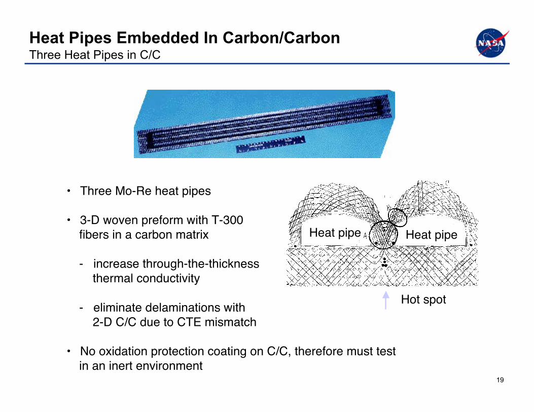
Heat Pipes Embedded In Carbon/CarbonThree Heat Pipes in C/C
• Three Mo-Re heat pipes
• 3-D woven preform with T-300 fibers in a carbon matrix
- increase through-the-thickness thermal conductivity
- eliminate delaminations with 2-D C/C due to CTE mismatch
• No oxidation protection coating on C/C, therefore must test in an inert environment
Hot spot
Heat pipeHeat pipe

2020
C/C Heat Pipe Transient Testing Three Heat Pipes in C/C
1400
1500
1600
1700
1800
1900
2000
Temp., °F
5000 5500 6000 6500
Time, sec
x = 30.0 in.
x = 27.4 in.
130 V
180 V
0
500
1000
1500
2000
2500
Temp, °F
0 600 1200 1800 2400 3000 3600
Time, sec.
Vertical
Horizontal
x = 2.9 in.,under
heaters
x = 30.0 in.

2121
• Numerous small specimens to study various issues
• Design validation heat pipe - 36-in-long straight heat pipe - Operated up to 2460°F (1350°C) - Throughput of 3.1 Btu/sec (3.3 kW) - Radial heat flux of 141 Btu/ft2-sec (160 W/cm2) - Developed leak due to difficulties with welded thermocouple
• Three straight heat pipes - 28-in-long - Operated up to 2300°F (1260°C) and 155 Btu/ft2-sec - Embedded in carbon/carbon - Testing to be performed at NASA LaRC
• J-tube heat pipe - 30-in-long - Nose and wick fabrication issues resolved - Transient performance tests at LANL
Heat-Pipe-Cooled Leading Edge Development
2222
Machine and Weld Nose RegionJ-Tube Heat Pipe
Photograph of nose parts

2323
Curved Wick Fabrication J-Tube Heat Pipe
Wick formedon mandrel
Nose portion of wickWick being formedaround machined part

2424
RF-Induction Heating of J-Tube Heat Pipe J-Tube Heat Pipe
• RF-induction coil/concentrator heating of nose region on outer surface • Test specific issue: Hot spot in nose region - Test - Curved surface not insulated, thus higher throughtput required - Flight vehicle - Curved surface is “insulated”

2525
J-Tube Heat-Pipe Checkout Tests
0
500
1000
1500
2000
Temp., °F
0 60 120 180 240 300 360 420 480
Time, min.
tc 1 - tc 8
Location of thermocouples
Start up of J-tube heat pipe Maximum temperature distribution(not steady state)
0
500
1000
1500
2000
Temp, °F
-5 0 5 10 15 20 25 30
Position, in.
Stagnation line
Test 1 Test 2
Test 4
Test 3
Test 1

2626
Test Induced Failure of Heat Pipe
• Nominal operation during 4 tests
• Test induced failure (concentrator arcing) during test 4 - Insulation outgassed during test (~0.1 Torr) - Ionization between heating coil and heat pipe
Burn through due toconcentrator arcing
J-tubeheat pipe
2727
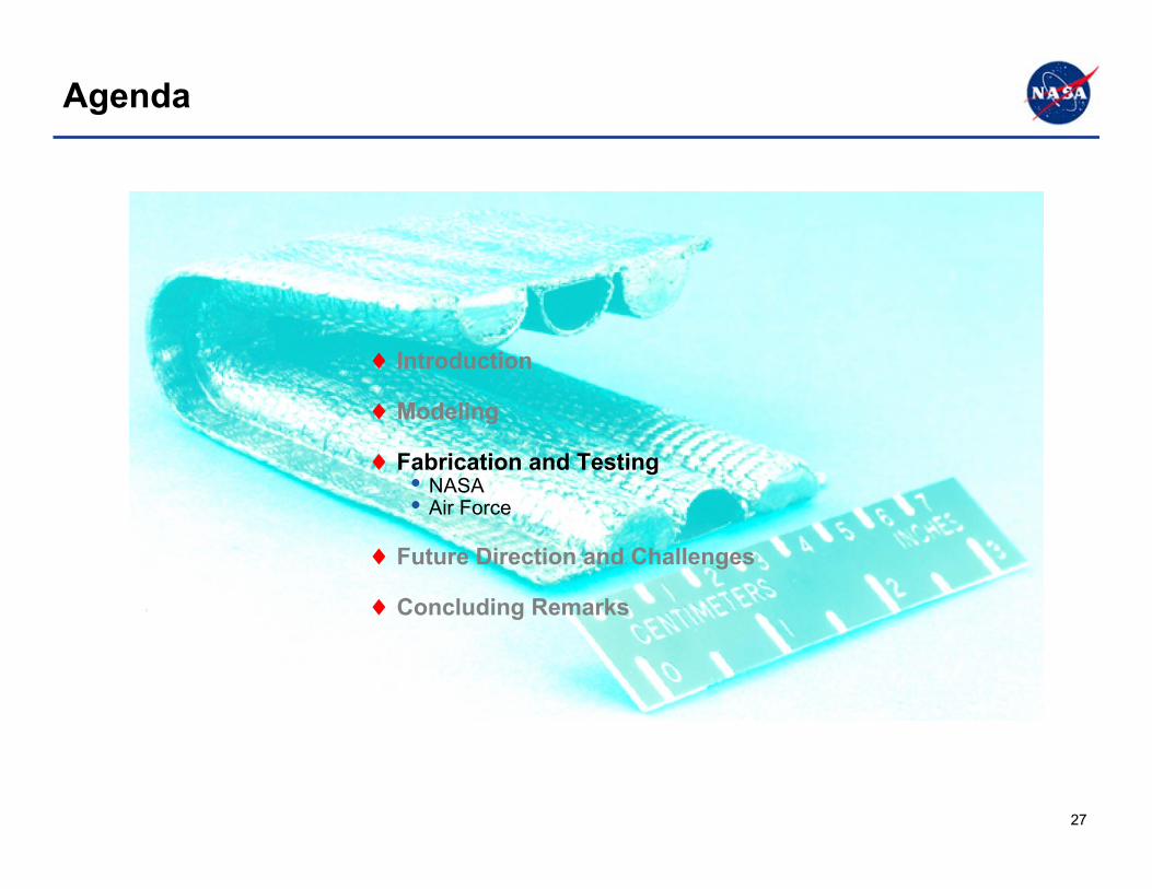
Agenda
♦ Introduction
♦ Modeling
♦ Fabrication and Testing• NASA• Air Force
♦ Future Direction and Challenges
♦ Concluding Remarks
2828
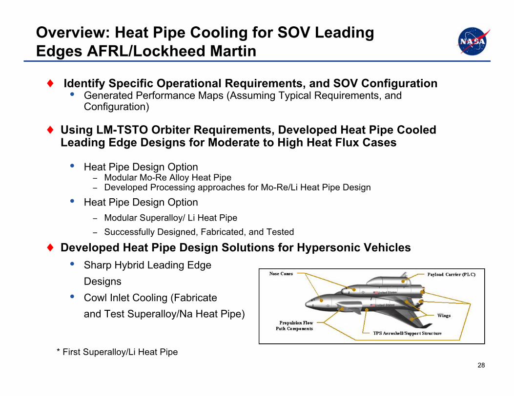
Overview: Heat Pipe Cooling for SOV LeadingEdges AFRL/Lockheed Martin
♦ Identify Specific Operational Requirements, and SOV Configuration• Generated Performance Maps (Assuming Typical Requirements, and
Configuration)
♦ Using LM-TSTO Orbiter Requirements, Developed Heat Pipe CooledLeading Edge Designs for Moderate to High Heat Flux Cases
• Heat Pipe Design Option− Modular Mo-Re Alloy Heat Pipe− Developed Processing approaches for Mo-Re/Li Heat Pipe Design
• Heat Pipe Design Option− Modular Superalloy/ Li Heat Pipe− Successfully Designed, Fabricated, and Tested
♦ Developed Heat Pipe Design Solutions for Hypersonic Vehicles• Sharp Hybrid Leading Edge
Designs• Cowl Inlet Cooling (Fabricate
and Test Superalloy/Na Heat Pipe)
* First Superalloy/Li Heat Pipe

2929
Performance Map for Heat Pipe Leading EdgeCooling
1000
1200
1400
1600
1800
2000
2200
2400
2600
2800
1500 1900 2000 2100 2200 2300 2400 2500 2600 2700 2800
Radiation Temperature, F
1000
1200
1400
1600
1800
2000
2200
2400
2600
2800
1500 1600 1700 1800 1900 2000 2100 2200 2300 2400 2500 2600 2700 2800
Rad
iatio
n Eq
uil.
Tem
p. o
n R
adia
ting
Surf
ace,
F
1.73
2.89
4.56
6.86
9.94
14.0
19.1
25.5
33.4
43.0
Hea
t Flu
x on
Rad
iatin
g Su
rfac
e, B
tu/ft
2 -se
c
0.5-in. radius0.8 emissivity65 Deb. Sweep angle
Stagnation Heat Flux50 Btu/ft2-sec
100 Btu/ft2-sec200 Btu/ft2-sec400 Btu/ft2-sec800 Btu/ft2-sec
Infinite Radiation length40-in. Radiation Length30-in. Radiation Length20-in. Radiation Length
Heat Source Zone for
Radiating Surface
• Generated Relationship Between the Cooling System Temperature and Radiation Length and Aerothermal Environment for Different Leading Edge Radii

3030
Technical Assessment of KeyHPCLE Design Options
♦ Key Design Options Very High Temp.• Modular Mo Alloy/Li Heat Pipe
• Modular (or D) Mo-Re/Li Heat Pipes Embedded in C-C or C/SiC
• Modular (or D) Mo-Re/Li Heat Pipe Design
♦ Key Design Options High Temp• Superalloy/ Li Heat Pipe
♦ Trade Study Criteria• Materials Cost• Machining• Joining• Heat Pipe Durability• Thermal Performance• Structural Performance• System Weight• Life Cycle Cost• Manufacturing Yield• Start-up Risk• Atmospheric Protection Risk• Repair/Rework
♦ Other System Level Concerns• Impact From Atmospheric Debris• Oxidation Resistance• Thermal Contact Resistance• Robustness in Flight of Ground• Toxicity of Li, in Case of Leak• Manufacturing and Ease of Integration• Comparison with Passive and Actively
Cooled Designs
Modular Mo-Re/LiHeat Pipe
Embedded C-C (Mo-Re Dshaped)/Li Heat Pipe
3131
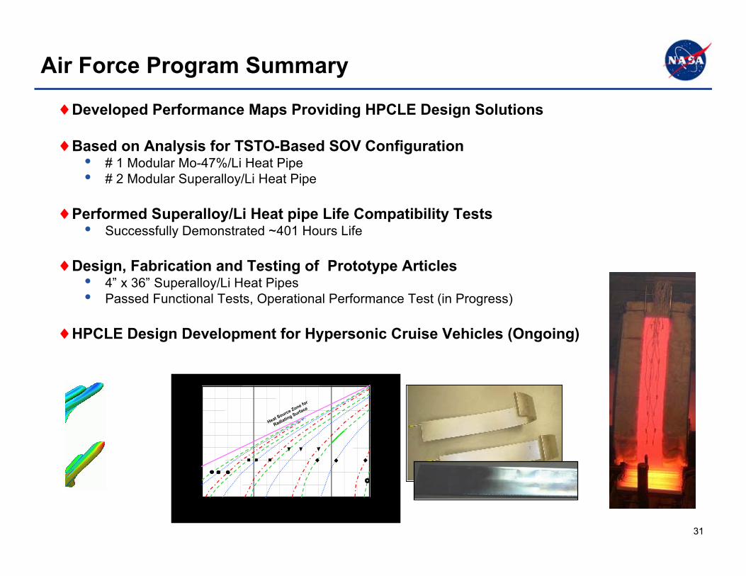
Air Force Program Summary
♦Developed Performance Maps Providing HPCLE Design Solutions
♦Based on Analysis for TSTO-Based SOV Configuration• # 1 Modular Mo-47%/Li Heat Pipe• # 2 Modular Superalloy/Li Heat Pipe
♦Performed Superalloy/Li Heat pipe Life Compatibility Tests• Successfully Demonstrated ~401 Hours Life
♦Design, Fabrication and Testing of Prototype Articles• 4” x 36” Superalloy/Li Heat Pipes• Passed Functional Tests, Operational Performance Test (in Progress)
♦HPCLE Design Development for Hypersonic Cruise Vehicles (Ongoing)
1000
1200
1400
1600
1800
2000
2200
2400
2600
2800
1500 1900 2000 2100 2200 2300 2400 2500 2600 2700 2800
Radiation Temperature, F
1000
1200
1400
1600
1800
2000
2200
2400
2600
2800
1500 1600 1700 1800 1900 2000 2100 2200 2300 2400 2500 2600 2700 2800
Rad
iati
on
Eq
uil. T
em
p. o
n R
ad
iati
ng
Su
rface, F
1.73
2.89
4.56
6.86
9.94
14.0
19.1
25.5
33.4
43.0
Heat
Flu
x o
n R
ad
iati
ng
Su
rface, B
tu/f
t2-s
ec
Heat Source Zone fo
r
Radiating Surfa
ce
1000
1200
1400
1600
1800
2000
2200
2400
2600
2800
1500 1900 2000 2100 2200 2300 2400 2500 2600 2700 2800
Radiation Temperature, F
1000
1200
1400
1600
1800
2000
2200
2400
2600
2800
1500 1600 1700 1800 19001500 1600 1700 1800 1900 2000 2100 2200 2300 2400 2500 2600 2700 2800
Rad
iati
on
Eq
uil. T
em
p. o
n R
ad
iati
ng
Su
rface, F
1.73
2.89
4.56
6.86
9.94
14.0
19.1
25.5
33.4
43.0
Heat
Flu
x o
n R
ad
iati
ng
Su
rface, B
tu/f
t2-s
ec
Heat Source Zone fo
r
Radiating Surfa
ce
3232
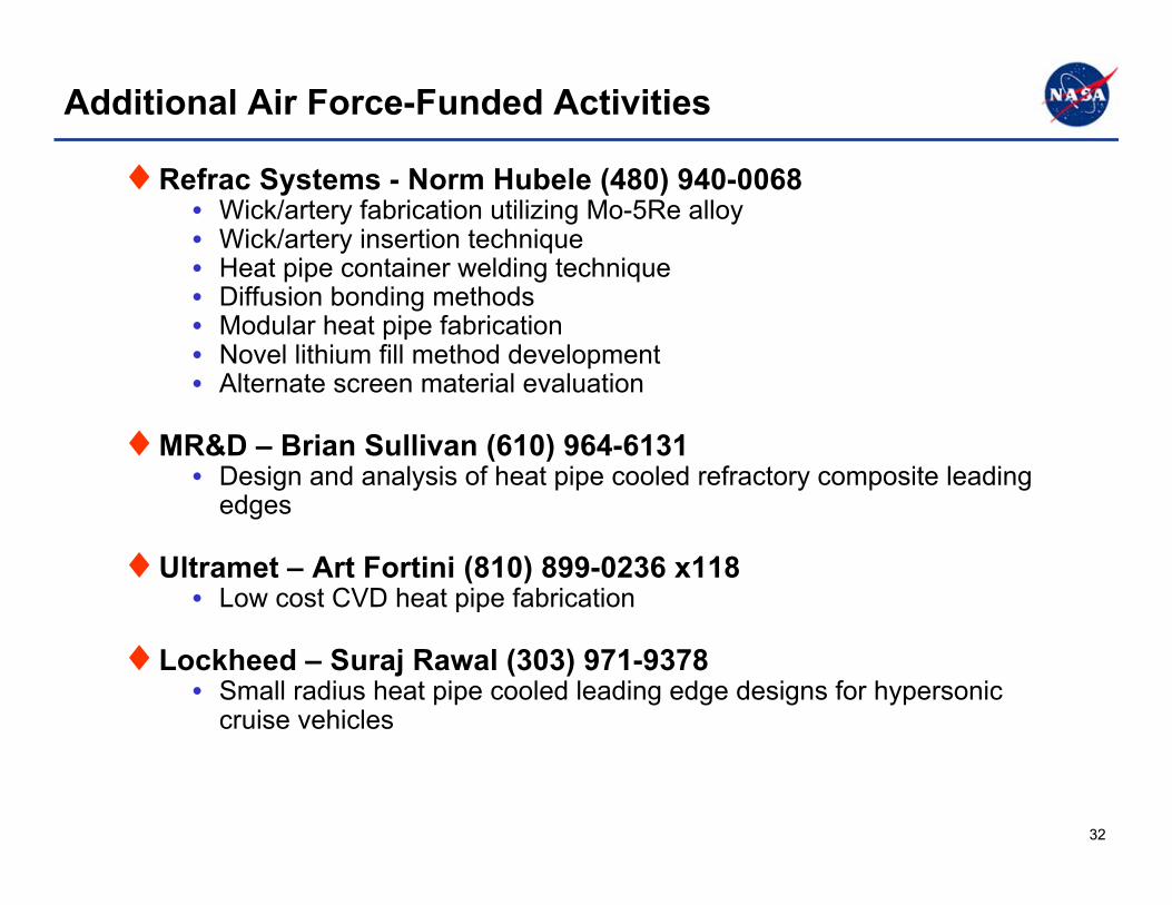
Additional Air Force-Funded Activities
♦Refrac Systems - Norm Hubele (480) 940-0068• Wick/artery fabrication utilizing Mo-5Re alloy• Wick/artery insertion technique• Heat pipe container welding technique• Diffusion bonding methods• Modular heat pipe fabrication• Novel lithium fill method development• Alternate screen material evaluation
♦MR&D – Brian Sullivan (610) 964-6131• Design and analysis of heat pipe cooled refractory composite leading
edges
♦Ultramet – Art Fortini (810) 899-0236 x118• Low cost CVD heat pipe fabrication
♦ Lockheed – Suraj Rawal (303) 971-9378• Small radius heat pipe cooled leading edge designs for hypersonic
cruise vehicles

3333
Agenda
♦ Introduction
♦Modeling
♦Fabrication and Testing
♦Future Direction and Challenges
♦Concluding Remarks

3434
Path Forward
♦For heat pipes to be utilized on the leading edges of flightvehicles•Designers must be willing to insert the technology•The payoff must be significant and the technical evolution not
♦High temperature heat pipe options•Superalloy or refractory metal•Embedded or not embedded
♦Superalloy heat pipes offer increased heat flux capability to thedesigner using “conventional” materials
♦Refractory metal heat pipes embedded in a refractorycomposite offer a significant increase in heat flux capability
3535
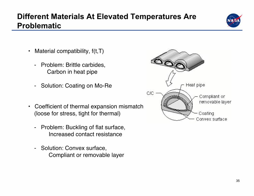
Different Materials At Elevated Temperatures AreProblematic
• Material compatibility, f(t,T)
- Problem: Brittle carbides, Carbon in heat pipe
- Solution: Coating on Mo-Re
• Coefficient of thermal expansion mismatch (loose for stress, tight for thermal) - Problem: Buckling of flat surface, Increased contact resistance
- Solution: Convex surface, Compliant or removable layer
3636
Agenda
♦ Introduction
♦Modeling
♦Fabrication and Testing
♦Future Direction and Challenges
♦Concluding Remarks
3737
Concluding Remarks
♦ Heat pipes can be used to effectively cool wing leadingedges of hypersonic vehicles
♦ Heat-pipe leading edge development• Design validation heat pipe testing confirmed design
• Three heat pipes embedded and tested in C/C• Single J-tube heat pipe fabricated and testing initiated
♦ HPCLE work is currently underway at several locations