Embed Size (px)
Citation preview
PEX Tubing Technical InformationINFO 5, page 1
L230
5 - N
ovem
ber 5
, 201
9
www.heatlink.com
®
Heat Link
The Material
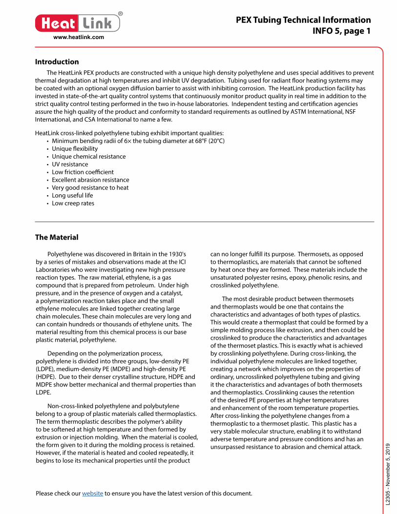
The HeatLink PEX products are constructed with a unique high density polyethylene and uses special additives to prevent thermal degradation at high temperatures and inhibit UV degradation. Tubing used for radiant floor heating systems may be coated with an optional oxygen diffusion barrier to assist with inhibiting corrosion. The HeatLink production facility has invested in state-of-the-art quality control systems that continuously monitor product quality in real time in addition to the strict quality control testing performed in the two in-house laboratories. Independent testing and certification agencies assure the high quality of the product and conformity to standard requirements as outlined by ASTM International, NSF International, and CSA International to name a few.
HeatLink cross-linked polyethylene tubing exhibit important qualities: • Minimum bending radii of 6× the tubing diameter at 68°F (20°C) • Unique flexibility • Unique chemical resistance • UV resistance • Low friction coefficient • Excellent abrasion resistance • Very good resistance to heat • Long useful life • Low creep rates
Polyethylene was discovered in Britain in the 1930's by a series of mistakes and observations made at the ICI Laboratories who were investigating new high pressure reaction types. The raw material, ethylene, is a gas compound that is prepared from petroleum. Under high pressure, and in the presence of oxygen and a catalyst, a polymerization reaction takes place and the small ethylene molecules are linked together creating large chain molecules. These chain molecules are very long and can contain hundreds or thousands of ethylene units. The material resulting from this chemical process is our base plastic material, polyethylene.
Depending on the polymerization process, polyethylene is divided into three groups, low-density PE (LDPE), medium-density PE (MDPE) and high-density PE (HDPE). Due to their denser crystalline structure, HDPE and MDPE show better mechanical and thermal properties than LDPE.
Non-cross-linked polyethylene and polybutylene belong to a group of plastic materials called thermoplastics. The term thermoplastic describes the polymer’s ability to be softened at high temperature and then formed by extrusion or injection molding. When the material is cooled, the form given to it during the molding process is retained. However, if the material is heated and cooled repeatedly, it begins to lose its mechanical properties until the product
can no longer fulfill its purpose. Thermosets, as opposed to thermoplastics, are materials that cannot be softened by heat once they are formed. These materials include the unsaturated polyester resins, epoxy, phenolic resins, and crosslinked polyethylene.
The most desirable product between thermosets and thermoplasts would be one that contains the characteristics and advantages of both types of plastics. This would create a thermoplast that could be formed by a simple molding process like extrusion, and then could be crosslinked to produce the characteristics and advantages of the thermoset plastics. This is exactly what is achieved by crosslinking polyethylene. During cross-linking, the individual polyethylene molecules are linked together, creating a network which improves on the properties of ordinary, uncrosslinked polyethylene tubing and giving it the characteristics and advantages of both thermosets and thermoplastics. Crosslinking causes the retention of the desired PE properties at higher temperatures and enhancement of the room temperature properties. After cross-linking the polyethylene changes from a thermoplastic to a thermoset plastic. This plastic has a very stable molecular structure, enabling it to withstand adverse temperature and pressure conditions and has an unsurpassed resistance to abrasion and chemical attack.
Introduction
Please check our website to ensure you have the latest version of this document.
PEX Tubing Technical InformationINFO 5, page 2
L230
5 - N
ovem
ber 5
, 201
9
www.heatlink.com
®
Heat Link
1 10 100 1 000 10 000 100 000 1 000 000
0
2
4
6
8
10
12(1740)
(1450)
(1160)
(870)
(580)
(290)
PEX (175˚F)
PEX (200˚F)
PB (200˚F) PB (175˚F)
1 10 255 50
Hours of Operation
Internal Pressure
Creep RuptureN/mm2
(psi)
Years
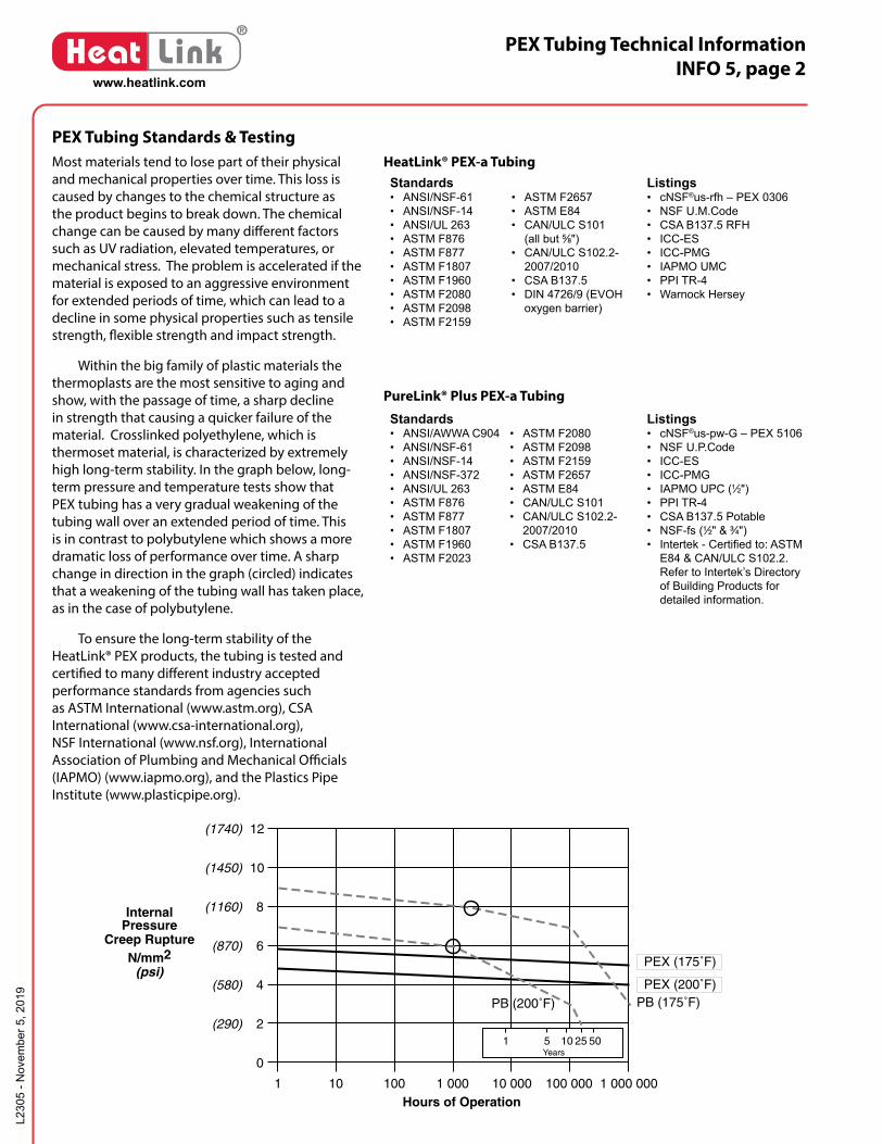
Most materials tend to lose part of their physical and mechanical properties over time. This loss is caused by changes to the chemical structure as the product begins to break down. The chemical change can be caused by many different factors such as UV radiation, elevated temperatures, or mechanical stress. The problem is accelerated if the material is exposed to an aggressive environment for extended periods of time, which can lead to a decline in some physical properties such as tensile strength, flexible strength and impact strength.
Within the big family of plastic materials the thermoplasts are the most sensitive to aging and show, with the passage of time, a sharp decline in strength that causing a quicker failure of the material. Crosslinked polyethylene, which is thermoset material, is characterized by extremely high long-term stability. In the graph below, long-term pressure and temperature tests show that PEX tubing has a very gradual weakening of the tubing wall over an extended period of time. This is in contrast to polybutylene which shows a more dramatic loss of performance over time. A sharp change in direction in the graph (circled) indicates that a weakening of the tubing wall has taken place, as in the case of polybutylene.
To ensure the long-term stability of the HeatLink® PEX products, the tubing is tested and certified to many different industry accepted performance standards from agencies such as ASTM International (www.astm.org), CSA International (www.csa-international.org), NSF International (www.nsf.org), International Association of Plumbing and Mechanical Officials (IAPMO) (www.iapmo.org), and the Plastics Pipe Institute (www.plasticpipe.org).
PEX Tubing Standards & Testing
®
LinkHeatwww.heatlink.com
All information is subject to change without notice.Please check our website to ensure you have the latest version of this document.
©2009-2019 HeatLink Group Inc.SUB94000
2019-05-24
HeatLink® PEX-a Tubing with Oxygen BarrierSubmittal - Page 2 of 2
InstallationInstallation of HeatLink® PEX tubing must follow all of HeatLink's instructions and guidelines, including those in the HeatLink Installation Guide, design information, and tubing layout drawings.
1 ⁄2" 5 ⁄8" 3 ⁄4" 1" 1-1 ⁄4"
1-1 ⁄2"
50 (11363)10 (2273)1 (227)0.1 (22.7)0.01 (2.27)
Water Flow Rate in US gpm (L/h)
0.05 (11.3) 0.5 (114) 5 (1137)
Pre
ssu
re D
rop
in f
t H
2O/1
00 f
t (m
bar
/m)
Can
als
o b
e u
sed
as
a P
erce
nt
Hea
dlo
ss (
%)
(eg
. 1%
Hea
dlo
ss =
1 f
t. H
2O/1
00 f
t o
f p
ipe)
10
1
0.1
0.01 (0.01)
(0.1)
(1)
(9.8)
0.05 (0.05)
0.5 (0.5)
5 (4.9)
Chart settings at 120˚F (49˚C)
PPI PEX Tubing Ratings
Temperature(°F / °C)
Plastics Pipe Institute - recommended HDB
(psi)
HydrostaticDesignStress(psi)
Resultant-pressure
Rating (psi)
73.4°F / 23°C* 1,250 630 160
180°F / 82.2°C* 800 400 100
200°F / 93.3°C 630 315 80
* HeatLink® PEX tubing is listed in PPI TR-4 for these pressure/temperature ratings.
Plenum RatingHeatLink PEX-a tubing has been tested in accordance with CAN/S102.2-2007/2010, Standard for Surface Burning Characteristics of Flooring, Floor Covering and Miscellaneous Materials and Assemblies and ASTM E84, Standard Test Method for Surface Burning Characteristics of Building Materials.
CAN/ULC 102.2-2007/2010 (Canada)
Product Size Flame Spread (FS)
SmokeDevelopment (SD)
Insulation Required
SpacingRequirements
HeatLink 1⁄2" <25 <50 No Min. 8" (20 cm)
HeatLink 1⁄2" - 1 1⁄4" <25 <50 Yes** None
ASTM E84 (United States)
Product Size Flame Spread (FS)
SmokeDevelopment (SD)
Insulation Required
SpacingRequirements
HeatLink 1⁄2" - 1 1⁄4" <25 <50 Yes** None
** Requires 1⁄2" thick fi berglass insulation
Related Documents• INFO 5 - PEX Tubing Technical Information (L2305)• HeatLink Installation Guide (L3390)• HeatLink Limited Heating Warranty
Standards• ANSI/NSF-61• ANSI/NSF-14• ANSI/UL 263• ASTM F876• ASTM F877• ASTM F1807• ASTM F1960• ASTM F2080• ASTM F2098• ASTM F2159
• ASTM F2657• ASTM E84• CAN/ULC S101
(all but 5⁄8")• CAN/ULC S102.2-
2007/2010• CSA B137.5• DIN 4726/9 (EVOH
oxygen barrier)
Listings• cNSF®us-rfh – PEX 0306• NSF U.M.Code• CSA B137.5 RFH• ICC-ES• ICC-PMG• IAPMO UMC• PPI TR-4• Warnock Hersey
Dimension Diagram
O.D.I.D.
Wall Thickness Length
SizeAverage O.D.
in (mm)
Min. Wall Thickness
in (mm)Average I.D.
in (mm)
Min. Bend Radiusin (mm)
Min. Coil I.D. in (mm)
PEX Weight lb/ft (kg/m)
Fluid Volume USG/ft (L/m)
PEX + Water Weight lb/ft (kg/m)
1⁄2" 0.625 (15.88) 0.070 (1.78) 0.475 (12.07) 3.0 (77) 15.7 (400) 0.053 (0.079) 0.0092 (0.114) 0.13 (0.193)5⁄8" 0.750 (19.05) 0.083 (2.12) 0.574 (14.56) 3.75 (95) 16.5 (420) 0.074 (0.110) 0.0134 (0.166) 0.19 (0.277)3⁄4" 0.875 (22.22) 0.097 (2.47) 0.671 (17.03) 4.5 (115) 18.9 (480) 0.100 (0.149) 0.0184 (0.228) 0.25 (0.377)1" 1.125 (28.58) 0.125 (3.18) 0.862 (21.89) 6.0 (153) 21.6 (550) 0.166 (0.248) 0.0303 (0.376) 0.42 (0.624)
1 1⁄4" 1.375 (34.92) 0.153 (3.88) 1.054 (26.78) 7.5 (191) 24.4 (620) 0.246 (0.367) 0.0453 (0.563) 0.62 (0.930)1 1⁄2" 1.625 (41.28) 0.181 (4.59) 1.244 (31.62) 9.0 (229) 31.5 (800) 0.345 (0.515) 0.0631 (0.785) 0.87 (1.300)®
LinkHeatwww.heatlink.com
All information is subject to change without notice.Please check our website to ensure you have the latest version of this document.
©2011-2019 HeatLink Group Inc.SUB20000
2019-05-24
PureLink® Plus Potable Water PEX-a Tubing (Blue)Submittal - Page 1 of 2
Chart settings at 120˚F (49˚C)
PPI PEX Tubing Ratings
Temperature(°F / °C)
Plastics Pipe Institute - recommended HDB
(psi)
HydrostaticDesignStress(psi)
Resultant-pressure
Rating (psi)
73.4°F / 23°C* 1,250 630 160
180°F / 82.2°C* 800 400 100
200°F / 93.3°C* 630 315 80
* PureLink Plus® PEX tubing is listed in PPI TR-4 for these pressure/temperature ratings.
InstallationInstallation of PureLink® and HeatLink® PEX tubing must follow all of HeatLink's instructions and guidelines.
Plenum RatingPureLink Plus PEX-a tubing has been tested in accordance with CAN/ULC S102.2-2007/2010, Standard for Surface Burning Characteristics of Flooring, Floor Covering and Miscellaneous Materials and Assemblies and ASTM E84, Standard Test Method for Surface Burning Characteristics of Building Materials.
CAN/ULC S102.2-2007/2010 (Canada)
Product Size Flame Spread (FS)
SmokeDevelopment (SD)
Insulation Required
SpacingRequirements
PureLink® Plus 1⁄2" <25 <50 No Min. 8" (20 cm)PureLink® Plus 1⁄2" - 2" <25 <50 Yes** None
ASTM E84 (United States)
Product Size Flame Spread (FS)
SmokeDevelopment (SD)
Insulation Required
SpacingRequirements
PureLink® Plus 1⁄2" & 3⁄4" <25 <50 No Min. 18" (46 cm)PureLink® Plus 1⁄2" - 2" <25 <50 Yes** None
Related Documents• INFO 5 - PEX Tubing Technical Information (L2305)• HeatLink Installation Guide (L3390)• Potable Water Systems Installation Guide (L3235)• HeatLink Limited Plumbing Warranty
** Requires 1⁄2" thick fi berglass insulation
Standards• ANSI/AWWA C904 • ANSI/NSF-61• ANSI/NSF-14• ANSI/NSF-372• ANSI/UL 263• ASTM F876• ASTM F877• ASTM F1807• ASTM F1960• ASTM F2023
• ASTM F2080• ASTM F2098• ASTM F2159• ASTM F2657• ASTM E84• CAN/ULC S101• CAN/ULC S102.2-
2007/2010• CSA B137.5
Listings• cNSF®us-pw-G – PEX 5106• NSF U.P.Code• ICC-ES• ICC-PMG• IAPMO UPC (1⁄2")• PPI TR-4• CSA B137.5 Potable• NSF-fs (1⁄2" & 3⁄4")• Intertek - Certifi ed to: ASTM
E84 & CAN/ULC S102.2. Refer to Intertek’s Directory of Building Products for detailed information.
SizeAverage O.D.
in (mm)
Min. Wall Thickness
in (mm)Average I.D.
in (mm)
Min. Bend Radiusin (mm)
Min. Coil I.D. in (mm)
PEX Weight lb/ft (kg/m)
Fluid Volume USG/ft (L/m)
PEX + Water Weight lb/ft (kg/m)
1⁄2" 0.625 (15.88) 0.070 (1.78) 0.475 (12.07) 3.0 (77) 15.7 (400) 0.053 (0.079) 0.0092 (0.114) 0.13 (0.193)3⁄4" 0.875 (22.22) 0.097 (2.47) 0.671 (17.03) 4.5 (115) 18.9 (480) 0.100 (0.149) 0.0184 (0.228) 0.25 (0.377)1" 1.125 (28.58) 0.125 (3.18) 0.862 (21.89) 6.0 (153) 21.6 (550) 0.166 (0.248) 0.0303 (0.376) 0.42 (0.624)
1 1⁄4" 1.375 (34.92) 0.153 (3.88) 1.054 (26.78) 7.5 (191) 24.4 (620) 0.246 (0.367) 0.0453 (0.563) 0.62 (0.930)1 1⁄2" 1.625 (41.28) 0.181 (4.59) 1.244 (31.62) 9.0 (229) 31.5 (800) 0.345 (0.515) 0.0631 (0.785) 0.87 (1.300)2" 2.125 (53.98) 0.236 (6.00) 1.629 (41.37) 12.0 (305) 39.4 (1000) 0.589 (0.878) 0.1083 (1.344) 1.49 (2.223)
Dimension Diagram
O.D.I.D.
Wall Thickness Length
HeatLink® PEX-a Tubing
PureLink® Plus PEX-a Tubing
PEX Tubing Technical InformationINFO 5, page 3
L230
5 - N
ovem
ber 5
, 201
9
www.heatlink.com
®
Heat Link
Standards ASTM F876/877, CSA B137.5, and NSF-14 cover the manufacture and testing of all PEX tubing. Multiple parameters are covered within these standards such as workmanship, dimensions and tolerances, density, pressure testing, and the degree of cross-linking. HeatLink® tubing meet and exceed the specified requirements in all cases.
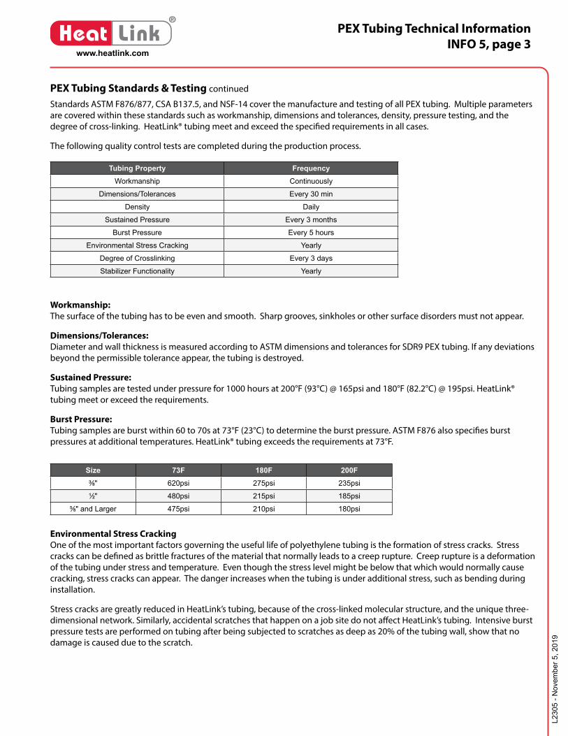
The following quality control tests are completed during the production process.
Workmanship:The surface of the tubing has to be even and smooth. Sharp grooves, sinkholes or other surface disorders must not appear.
Dimensions/Tolerances: Diameter and wall thickness is measured according to ASTM dimensions and tolerances for SDR9 PEX tubing. If any deviations beyond the permissible tolerance appear, the tubing is destroyed.
Sustained Pressure:Tubing samples are tested under pressure for 1000 hours at 200°F (93°C) @ 165psi and 180°F (82.2°C) @ 195psi. HeatLink® tubing meet or exceed the requirements.
Burst Pressure:Tubing samples are burst within 60 to 70s at 73°F (23°C) to determine the burst pressure. ASTM F876 also specifies burst pressures at additional temperatures. HeatLink® tubing exceeds the requirements at 73°F.
PEX Tubing Standards & Testing continued
Tubing Property FrequencyWorkmanship Continuously
Dimensions/Tolerances Every 30 min
Density Daily
Sustained Pressure Every 3 months
Burst Pressure Every 5 hours
Environmental Stress Cracking Yearly
Degree of Crosslinking Every 3 days
Stabilizer Functionality Yearly
Size 73F 180F 200F3⁄8" 620psi 275psi 235psi1⁄2" 480psi 215psi 185psi
5⁄8" and Larger 475psi 210psi 180psi
Environmental Stress CrackingOne of the most important factors governing the useful life of polyethylene tubing is the formation of stress cracks. Stress cracks can be defined as brittle fractures of the material that normally leads to a creep rupture. Creep rupture is a deformation of the tubing under stress and temperature. Even though the stress level might be below that which would normally cause cracking, stress cracks can appear. The danger increases when the tubing is under additional stress, such as bending during installation.
Stress cracks are greatly reduced in HeatLink’s tubing, because of the cross-linked molecular structure, and the unique three-dimensional network. Similarly, accidental scratches that happen on a job site do not affect HeatLink’s tubing. Intensive burst pressure tests are performed on tubing after being subjected to scratches as deep as 20% of the tubing wall, show that no damage is caused due to the scratch.

PEX Tubing Technical InformationINFO 5, page 4
L230
5 - N
ovem
ber 5
, 201
9
www.heatlink.com
®
Heat Link
Degree of Crosslinking:The outstanding properties of HeatLink® tubing is a result of crosslinking the polyethylene. The quality of the tubing depends on the degree of crosslinking. “Degree of crosslinking” represents the percentage of crosslinked material compared to the total mass. This value should not be below 70% for peroxide crosslinked tubing (PEX-a), 65% for vinyl-silane crosslinked tubing (PEX-b), and 65% for electron beam crosslinked tubing (PEX-c). At a lower percentage the characteristics of crosslinked material are not dominant. To test this percentage, a section cut from that sample that represents the entire wall thickness and it is boiled in a solvent, extracting the non-crosslinked portion of the material. Tubing that does not meet the set requirements is destroyed.
Stabilizer Functionality:Ensures that the antioxidant package used to protect the tubing is functioning properly. Samples are tested for 3000h at 120°C (248°F) and 101psi (0.70MPa).
PEX Pressure/Temperature RatingsAll PEX products are evaluated with ASTM D2837 as an indication of the long-term performance of the product. Through evaluation of the test data at The Plastics Pipe Institute (PPI), PEX products are assigned ratings that govern the maximum operating pressure and temperatures.
Temperature Pressure HDB HDS73F (23C) 1 160psi (1100kPa) 1 1250psi 630psi
180F (82C) 1 100psi (690kPa) 1 800psi 400psi
200F (93C) 2 80psi (550kPa) 2 630psi 315psi
1 PureLink Plus, and HeatLink PEX Tubing have been listed to these pressure/temperature ratings as per PPI TR4.2 PureLink Plus PEX Tubing has been listed to these pressure/temperature ratings as per PPI TR4.HDB - Hydrostatic Design BasisHDS - Hydrostatic Design Stress
PEX Tubing Standards & Testing continued
Interpolated & Extrapolated Pressure/Temperature RatingsAdditional pressure/temperature ratings are determined using a linear interpolation and polynomial trendline extrapolation.
The use of PEX tubing in a potable hot-water plumbing system with an operating temperature above 140°F (60°C) or system pressure above 80 psig (550 kPaG) or highly aggressive water quality or any combination thereof can significantly reduce the service life of the tubing. This statement does not apply to closed loop hydronic systems.
HeatLink requires following the guidelines described in Plastics Pipe Institute TN-53, Guide to Chlorine Resistance Ratings of PEX Pipes and Tubing for Potable Water Applications and HeatLink INFO 37, Domestic Hot Water Recirculation Systems.
Temperature Pressure200.0F (93.3C) 80psi (552kPa)190.0F (87.8C) 90psi (621kPa)
180.0F (82.2C) 100psi (689kPa)170.0F (76.7C) 106psi (731kPa)
160.0F (71.1C) 111psi (765kPa)
150.0F (65.6C) 117psi (807kPa)
140.0F (60.0C) 123psi (848kPa)
130.0F (54.4C) 128psi (883kPa)
120.0F (48.9C) 134psi (924kPa)
110.0F (43.3C) 139psi (958kPa)
100.0F (37.8C) 145psi (1000kPa)
90.0F (32.2C) 151psi (1041kPa)
80.0F (26.7C) 156psi (1076kPa)
73.4F (23.0C) 160psi (1103kPa)60.0F (15.6C) 162psi (1117kPa)
50.0F (10.0C) 162psi (1117kPa)
40.0F (4.4C) 162psi (1117kPa)
PEX Tubing Technical InformationINFO 5, page 5
L230
5 - N
ovem
ber 5
, 201
9
www.heatlink.com
®
Heat Link
No Minimum
½" Thick Fiberglass Insulation
½" to 1-¼" HeatLink PEX-a Tubing or½" to 2" PureLink Plus PEX-a Tubing
No Minimum
½" Thick Fiberglass Insulation
½" to 1-¼" HeatLink PEX-a Tubing or½" to 2" PureLink Plus PEX-a Tubing
Minimum 18" (46 cm)
½" or ¾" PureLink Plus PEX-a Tubing(no insulation)
Minimum 8" (20 cm)
½" PureLink Plus or HeatLink PEX-aTubing (no insulation)
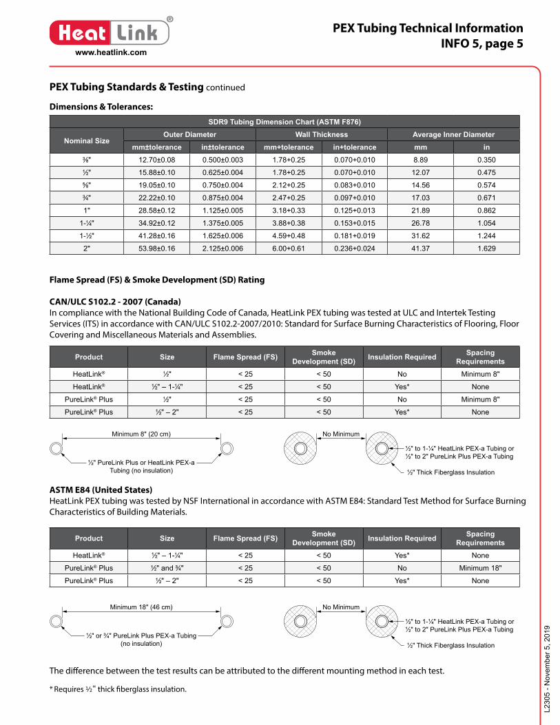
SDR9 Tubing Dimension Chart (ASTM F876)
Nominal SizeOuter Diameter Wall Thickness Average Inner Diameter
mm±tolerance in±tolerance mm+tolerance in+tolerance mm in3⁄8" 12.70±0.08 0.500±0.003 1.78+0.25 0.070+0.010 8.89 0.3501⁄2" 15.88±0.10 0.625±0.004 1.78+0.25 0.070+0.010 12.07 0.4755⁄8" 19.05±0.10 0.750±0.004 2.12+0.25 0.083+0.010 14.56 0.5743⁄4" 22.22±0.10 0.875±0.004 2.47+0.25 0.097+0.010 17.03 0.671
1" 28.58±0.12 1.125±0.005 3.18+0.33 0.125+0.013 21.89 0.862
1-1⁄4" 34.92±0.12 1.375±0.005 3.88+0.38 0.153+0.015 26.78 1.054
1-1⁄2" 41.28±0.16 1.625±0.006 4.59+0.48 0.181+0.019 31.62 1.244
2" 53.98±0.16 2.125±0.006 6.00+0.61 0.236+0.024 41.37 1.629
PEX Tubing Standards & Testing continued
Dimensions & Tolerances:
Product Size Flame Spread (FS) Smoke Development (SD) Insulation Required Spacing
RequirementsHeatLink® 1⁄2" < 25 < 50 No Minimum 8"
HeatLink® 1⁄2" – 1-1⁄4" < 25 < 50 Yes* None
PureLink® Plus 1⁄2" < 25 < 50 No Minimum 8"
PureLink® Plus 1⁄2" – 2" < 25 < 50 Yes* None
Product Size Flame Spread (FS) Smoke Development (SD) Insulation Required Spacing
RequirementsHeatLink® 1⁄2" – 1-1⁄4" < 25 < 50 Yes* None
PureLink® Plus 1⁄2" and 3⁄4" < 25 < 50 No Minimum 18"
PureLink® Plus 1⁄2" – 2" < 25 < 50 Yes* None
Flame Spread (FS) & Smoke Development (SD) Rating
CAN/ULC S102.2 - 2007 (Canada) In compliance with the National Building Code of Canada, HeatLink PEX tubing was tested at ULC and Intertek Testing Services (ITS) in accordance with CAN/ULC S102.2-2007/2010: Standard for Surface Burning Characteristics of Flooring, Floor Covering and Miscellaneous Materials and Assemblies.
ASTM E84 (United States) HeatLink PEX tubing was tested by NSF International in accordance with ASTM E84: Standard Test Method for Surface Burning Characteristics of Building Materials.
The difference between the test results can be attributed to the different mounting method in each test.
* Requires ½" thick fiberglass insulation.

PEX Tubing Technical InformationINFO 5, page 6
L230
5 - N
ovem
ber 5
, 201
9
www.heatlink.com
®
Heat Link
Technical SpecificationsMechanical Properties PEX-a
(Engel/Peroxide)PEX-b
(Silane)PEX-c
(Irradiation)Unit Standard
TestedDensity 930-938 947-950 942-945 kg/m3 ASTM F876
Flexibility for Installation Highest Lowest Middle
Tensile strength @ 20°C 20-26 ~20 23-26 N/mm2 DIN 53455
@ 100°C 9-13 ~12 9-13 N/mm2
Modulus of elasticity E @ 20°C 1150 ~750 600-900 N/mm2 DIN 53457
@ 80°C 560 N/A*** 400 N/mm2
Elongation on failure @ 20°C 300-450 >300 500-700 % DIN 53455
@ 100°C 500-700 N/A*** 750-900 %
Impact strength @ 20°C No failure No failure No failure kJ/m2 DIN 53453
@ -140°C No failure No failure No failure* kJ/m2
Moisture absorption @ 22°C 0.01 0.01 0.01 mg/4d DIN 53472
Coefficient of friction on steel 0.08-0.1 0.08-0.1 0.08-0.1 -
Surface energy 34 × 10-3 34 × 10-3 34 × 10-3 N/m
Oxygen permeability @ 20°C 0.7 × 10⁻³ 0.7 × 10⁻³ 0.7 × 10⁻³ g/m3 day DIN 4726
@ 55°C 2.6 × 10⁻³ 2.6 × 10⁻³ 2.6 × 10⁻³ g/m3 day
ESCR (environmental cracking) No failure No failure No failure ASTM F876
Degree of Crosslinking 70 to 89 65 to 89 65 to 89 % ASTM F876
Molecular Crosslink Bond Strength Carbon-Carbon - 144
Carbon-Silane - 104
Carbon-Carbon - 144
kcal/mol
Thermal Properties PEX-a (Engel/Peroxide)
PEX-b (Silane)
PEX-c (Irradiation)
Unit
Service temperature range -100, +120 -100, +120 -100, +120 °C
Coefficient of linear expansion** @ 20°C 1.4 × 10⁻⁴ 1.4 × 10⁻⁴ 1.4 × 10⁻⁴ m/m°C
@ 100°C 2.05 × 10⁻⁴ 2.05 × 10⁻⁴ 2.05 × 10⁻⁴ m/m°C
Softening temperature +133 +133 +133 °C
Specific heat 2.3 2.3 2.3 kJ/kg°C
Coefficient of thermal conductivity 0.38 0.38 0.38 W/m°C
Electrical Properties PEX-a (Engel/Peroxide)
PEX-b (Silane)
PEX-c (Irradiation)
Unit
Specific internal resistance @ 20°C 1015 1015 1015 -m
Dielectric constant @ 20°C 2.3 2.3 2.3 -
Dielectric loss factor @ 20°C / 50 Hz
1 × 10⁻³ 1 × 10⁻³ 1 × 10⁻³ -
Rupture voltage @ 20°C 60-90 60-90 60-90 kV/mm
* tested at - 80°C** Rule of thumb: PEX tubing will expand or contract approximately 1" every 100' of tubing for every 10°F of temperature change.*** Data not available at time of print
PEX Tubing Technical InformationINFO 5, page 7
L230
5 - N
ovem
ber 5
, 201
9
www.heatlink.com
®
Heat Link
PEX Tubing Physical Properties
PEX Tubing SizeWater Volume Content Rate of Thermal Conduction through the Tubing
Wall*US gal/ft Litres/m BTU/h/Ft/°F W/(m °C)
1⁄2" 0.0092 0.114 5.04 8.705⁄8" 0.0134 0.166 5.17 8.883⁄4" 0.0184 0.228 5.21 8.98
1" 0.0303 0.376 5.19 8.95
1-1⁄4" 0.0453 0.563 5.20 9.00
1-1⁄2" 0.0631 0.785 5.17 8.96
2" 0.1083 1.344 5.20 8.97
* Coefficient of Thermal Conductivity: 2.635 BTU/h/ft2/(°F/in) 0.38 W/(m °K)
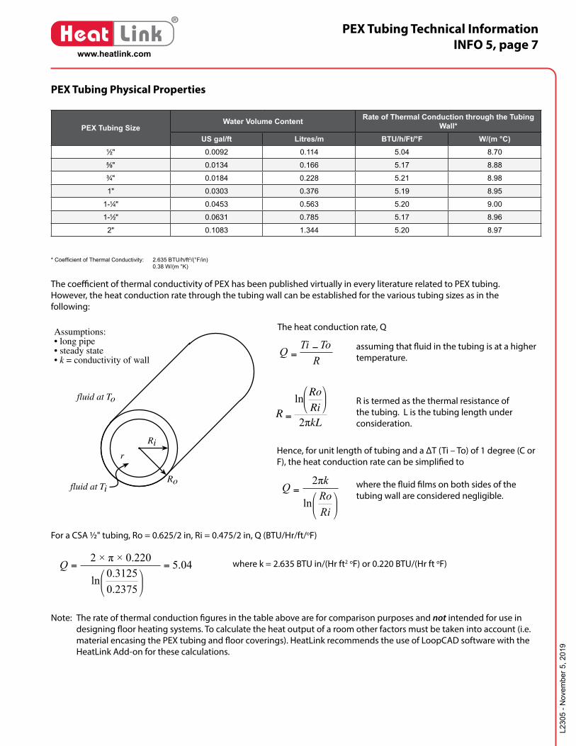
The coefficient of thermal conductivity of PEX has been published virtually in every literature related to PEX tubing. However, the heat conduction rate through the tubing wall can be established for the various tubing sizes as in the following:
RToTiQ −
=
R =
lnRo
Ri2πkL
5.04
0.23750.3125ln
2 × π × 0.220==Q
=
RiRo
Qln
2πk
Ri
Ro
fluid at To
fluid at Ti
r
Assumptions:• long pipe• steady state• k = conductivity of wall
The heat conduction rate, Q
R is termed as the thermal resistance of the tubing. L is the tubing length under consideration.
Hence, for unit length of tubing and a ∆T (Ti – To) of 1 degree (C or F), the heat conduction rate can be simplified to
assuming that fluid in the tubing is at a higher temperature.
where the fluid films on both sides of the tubing wall are considered negligible.
For a CSA ½" tubing, Ro = 0.625/2 in, Ri = 0.475/2 in, Q (BTU/Hr/ft/oF)
where k = 2.635 BTU in/(Hr ft2 oF) or 0.220 BTU/(Hr ft oF)
Note: The rate of thermal conduction figures in the table above are for comparison purposes and not intended for use in designing floor heating systems. To calculate the heat output of a room other factors must be taken into account (i.e. material encasing the PEX tubing and floor coverings). HeatLink recommends the use of LoopCAD software with the HeatLink Add-on for these calculations.
PEX Tubing Technical InformationINFO 5, page 8
L230
5 - N
ovem
ber 5
, 201
9
www.heatlink.com
®
Heat Link
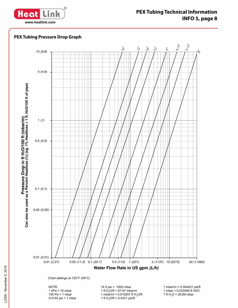
PEX Tubing Pressure Drop Graph
14.5 psi = 1000 mbar1 ft H2O/ft = 97.97 mbar/m1 mbar/m = 0.010207 ft H2O/ft1 ft H2O/ft = 0.4331 psi/ft
NOTE:1 kPa = 10 mbar100 Pa = 1 mbar0.0145 psi = 1 mbar
1 mbar/m = 0.004421 psi/ft1 mbar = 0.033456 ft H2O1 ft H2O = 29.89 mbar
3 ⁄8" 1 ⁄2" 5 ⁄8" 3 ⁄4" 1" 1-1 ⁄4"
1-1 ⁄2"
2"
50 (11363)10 (2273)1 (227)0.1 (22.7)0.01 (2.27)
Water Flow Rate in US gpm (L/h)
0.05 (11.3) 0.5 (114) 5 (1137)
Pre
ssu
re D
rop
in f
t H
2O/1
00 f
t (m
bar
/m)
Can
als
o b
e u
sed
as
a P
erce
nt
Hea
dlo
ss (
%)
(eg
. 1%
Hea
dlo
ss =
1 f
t. H
2O/1
00 f
t o
f p
ipe)
10
1
0.1
0.01 (0.01)
(0.1)
(1)
(9.8)
0.05 (0.05)
0.5 (0.5)
5 (4.9)
Chart settings at 120°F (49°C)
PEX Tubing Technical InformationINFO 5, page 9
L230
5 - N
ovem
ber 5
, 201
9
www.heatlink.com
®
Heat Link
Oxygen diffusion is the movement of oxygen across the wall of the polyethylene tubing over time. Oxygen can enter a closed loop hydronic heating system in many different ways such as through expansion tanks, air vents, fittings, in the makeup water and through the tubing. Plastic and rubber products are far more porous than metals. While air does not travel through the pores of these materials, an oxygen molecule can. There-fore the oxygen is not visible in the form of bubbles and cannot be eliminated by automatic air vents or air scoops. The operating pressure of the system does not affect the rate of diffusion because the oxygen starved water acts as a negative pressure as far as oxygen is concerned.
When corrosion of ferrous metals occurs in a closed loop heating system the water becomes “oxygen poor.” This occurs because the water gives up one of its oxygen molecules to the corrosion reaction. This oxygen poor water then needs to rebuild itself by drawing in oxygen from wherever it can. Oxygen is then pulled in through the porous walls of the polyethylene tubing and once replenished, the corrosion process continues.
The effects of oxygen diffusion in radiant heating systems can be limited to established standards by utilizing tubing with an oxygen barrier. HeatLink PEX tubing is available with an oxygen barrier that allows low gas permeability.
What is Oxygen Diffusion?
What are the answers?
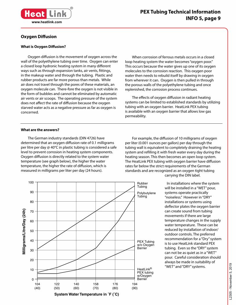
The German industry standards (DIN 4726) have determined that an oxygen diffusion rate of 0.1 milligrams per litre per day @ 40°C in plastic tubing is considered a safe level to prevent corrosion in heating system components. Oxygen diffusion is directly related to the system water temperature (see graph below), the higher the water temperature, the higher the rate of diffusion, which is measured in milligrams per liter per day (24 hours).
For example, the diffusion of 10 milligrams of oxygen per liter (0.001 ounces per gallon) per day through the tubing wall is equivalent to completely draining the heating system and refilling it with fresh water every day during the heating season. This then becomes an open loop system. The HeatLink PEX tubing with oxygen barrier have diffusion rates far below the strict requirements of the German standards and are recognized as an oxygen tight tubing
carrying the DIN label.
In installations where the system will be installed in a “WET” pour, systems operate practically “noiseless.” However in “DRY” installations or systems using deflector plates the oxygen barrier can create sound from tubing movements if there are large temperature changes in the supply water temperature. These can be reduced by installation of indoor/outdoor controls. The preferred recommendation for a “Dry” system is to use HeatLink standard PEX tubing. Even so the “DRY” system can not be as quiet as in a “WET” pour. Careful consideration should always be made in suitability of “WET” and “DRY” systems.
104(40)
122(50)
140(60)
158(70)
176(80)
194(90)
0
10
20
30
40
50
60
70
80
90
100
System Water Temperature in ˚F (˚C)
RubberTubing
PolybutyleneTubing
PEX Tubingw/o OxygenBarrier
HeatLink®
PEX tubingw/OxygenBarrier
Mill
igra
ms/
Lit
re/D
ay (
24h
)
Oxygen Diffusion

PEX Tubing Technical InformationINFO 5, page 10
L230
5 - N
ovem
ber 5
, 201
9
www.heatlink.com
®
Heat Link
Are there other solutions?
Heat exchangers may be used to isolate the tubing of the radiant system from the ferrous metals in the total system. The heat exchange method eliminates the need for a tube with an oxygen barrier. This alternative adds cost to the installation and therefore may not be economical. Also there are performance restrictions to heat exchangers that may not be acceptable in some installations.
Corrosion inhibitors such as molybdate or nitrite inhibitors must be added to the system to provide total corrosion control. Oxygen is not the only cause of corrosion. Corrosion can also occur in many other forms such as galvanic, caustic or acidic corrosion to name a few. The molybdate and nitrite operate by forming a thin film layer on all metallic parts in the water. This thin film is what provides the protection. See INFO 29 for dosages and details on the corrosion inhibitors. Even with the corrosion inhibitors in the system, oxygen continues to build in concentration but this should not be a concern as long as the inhibitor concentration is maintained. Homeowners and commercial operators must annually test these levels to ensure that
accelerated corrosion does not occur if inhibitors become diluted. Glycol freeze protection fluids can be purchased with inhibitors. These products are important in extreme climate applications and also in HeatLink® SnowMelt installations. A side benefit to these fluids is the lubrication/coating they provide to mixing valves and pumps.
In the above cases HeatLink® PEX may be used. This standard tubing has the same temperature and pressure performance capabilities as all of the HeatLink® PEX tubing that come with oxygen barrier.
For final tubing selections please see your HeatLink® representative who can give expert advice for your application.
Oxygen Diffusion
Kinked Tubing Repair
One of the most important features of PureLink® crosslinked tubing is its ability to “memorize” its structure and shape. As such, a kinked area can be heated with an electric hot air gun to approximately 260°F (125°C). Please note that open flame can not be used. Heat should be applied evenly until tubing appears clear around its entire circumference. Let the tubing cool undisturbed at room temperature. The repair is now complete.
Note: Colored tubing will not turn clear. O2 barrier will curl back from heated area.
Spray foam insulation
Spray foam insulation can be used in place of batt insulation in DryBelow™ applications. Direct contact of the PEX tubing and spray foam is not recommended. Use a foil barrier to separate them and to keep the foam from getting between the tubing, heat transfer plates, and the subfloor.
L230
5 - N
ovem
ber 5
, 201
9
www.heatlink.com
®
Heat Link PEX Tubing Chemical ResistanceINFO 5, page 11
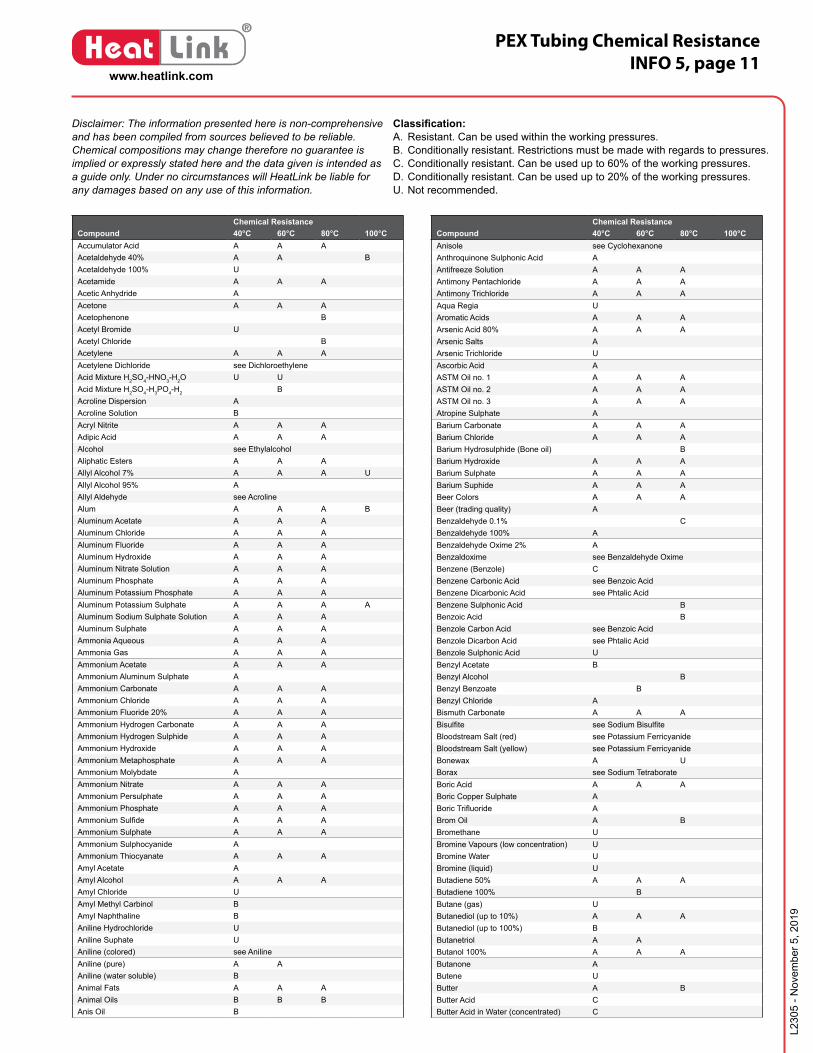
Disclaimer: The information presented here is non-comprehensive and has been compiled from sources believed to be reliable. Chemical compositions may change therefore no guarantee is implied or expressly stated here and the data given is intended as a guide only. Under no circumstances will HeatLink be liable for any damages based on any use of this information.
Classification:A. Resistant. Can be used within the working pressures.B. Conditionally resistant. Restrictions must be made with regards to pressures.C. Conditionally resistant. Can be used up to 60% of the working pressures.D. Conditionally resistant. Can be used up to 20% of the working pressures.U. Not recommended.
Chemical ResistanceCompound 40°C 60°C 80°C 100°CAccumulator Acid A A AAcetaldehyde 40% A A BAcetaldehyde 100% UAcetamide A A AAcetic Anhydride AAcetone A A AAcetophenone BAcetyl Bromide UAcetyl Chloride BAcetylene A A AAcetylene Dichloride see DichloroethyleneAcid Mixture H2SO4-HNO3-H2O U UAcid Mixture H2SO4-H3PO4-H2 BAcroline Dispersion AAcroline Solution BAcryl Nitrite A A AAdipic Acid A A AAlcohol see EthylalcoholAliphatic Esters A A AAllyl Alcohol 7% A A A UAllyl Alcohol 95% AAllyl Aldehyde see AcrolineAlum A A A BAluminum Acetate A A AAluminum Chloride A A AAluminum Fluoride A A AAluminum Hydroxide A A AAluminum Nitrate Solution A A AAluminum Phosphate A A AAluminum Potassium Phosphate A A AAluminum Potassium Sulphate A A A AAluminum Sodium Sulphate Solution A A AAluminum Sulphate A A AAmmonia Aqueous A A AAmmonia Gas A A AAmmonium Acetate A A AAmmonium Aluminum Sulphate AAmmonium Carbonate A A AAmmonium Chloride A A AAmmonium Fluoride 20% A A AAmmonium Hydrogen Carbonate A A AAmmonium Hydrogen Sulphide A A AAmmonium Hydroxide A A AAmmonium Metaphosphate A A AAmmonium Molybdate AAmmonium Nitrate A A AAmmonium Persulphate A A AAmmonium Phosphate A A AAmmonium Sulfide A A AAmmonium Sulphate A A AAmmonium Sulphocyanide AAmmonium Thiocyanate A A AAmyl Acetate AAmyl Alcohol A A AAmyl Chloride UAmyl Methyl Carbinol BAmyl Naphthaline BAniline Hydrochloride UAniline Suphate UAniline (colored) see AnilineAniline (pure) A AAniline (water soluble) BAnimal Fats A A AAnimal Oils B B BAnis Oil B
Chemical ResistanceCompound 40°C 60°C 80°C 100°CAnisole see CyclohexanoneAnthroquinone Sulphonic Acid AAntifreeze Solution A A AAntimony Pentachloride A A AAntimony Trichloride A A AAqua Regia UAromatic Acids A A AArsenic Acid 80% A A AArsenic Salts AArsenic Trichloride UAscorbic Acid AASTM Oil no. 1 A A AASTM Oil no. 2 A A AASTM Oil no. 3 A A AAtropine Sulphate ABarium Carbonate A A ABarium Chloride A A ABarium Hydrosulphide (Bone oil) BBarium Hydroxide A A ABarium Sulphate A A ABarium Suphide A A ABeer Colors A A ABeer (trading quality) ABenzaldehyde 0.1% CBenzaldehyde 100% ABenzaldehyde Oxime 2% ABenzaldoxime see Benzaldehyde OximeBenzene (Benzole) CBenzene Carbonic Acid see Benzoic AcidBenzene Dicarbonic Acid see Phtalic AcidBenzene Sulphonic Acid BBenzoic Acid BBenzole Carbon Acid see Benzoic AcidBenzole Dicarbon Acid see Phtalic AcidBenzole Sulphonic Acid UBenzyl Acetate BBenzyl Alcohol BBenzyl Benzoate BBenzyl Chloride ABismuth Carbonate A A ABisulfite see Sodium BisulfiteBloodstream Salt (red) see Potassium FerricyanideBloodstream Salt (yellow) see Potassium FerricyanideBonewax A UBorax see Sodium TetraborateBoric Acid A A ABoric Copper Sulphate ABoric Trifluoride ABrom Oil A BBromethane UBromine Vapours (low concentration) UBromine Water UBromine (liquid) UButadiene 50% A A AButadiene 100% BButane (gas) UButanediol (up to 10%) A A AButanediol (up to 100%) BButanetriol A AButanol 100% A A AButanone AButene UButter A BButter Acid CButter Acid in Water (concentrated) C
L230
5 - N
ovem
ber 5
, 201
9
www.heatlink.com
®
Heat Link PEX Tubing Chemical ResistanceINFO 5, page 12
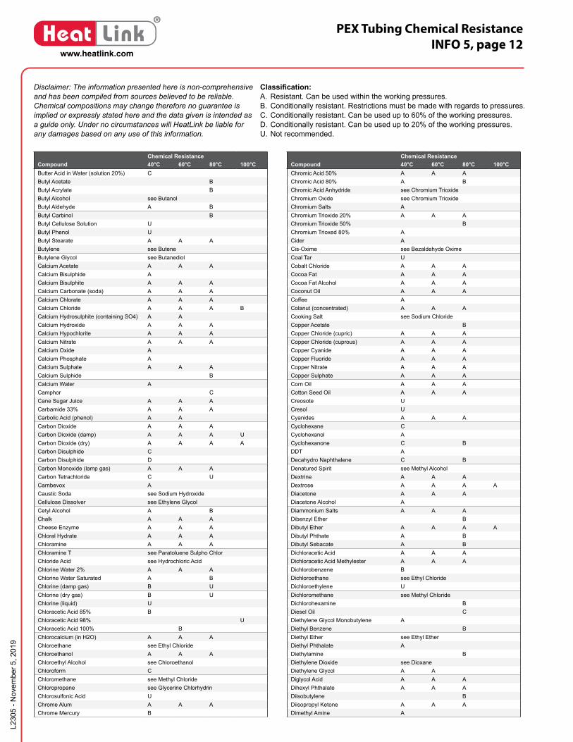
Disclaimer: The information presented here is non-comprehensive and has been compiled from sources believed to be reliable. Chemical compositions may change therefore no guarantee is implied or expressly stated here and the data given is intended as a guide only. Under no circumstances will HeatLink be liable for any damages based on any use of this information.
Classification:A. Resistant. Can be used within the working pressures.B. Conditionally resistant. Restrictions must be made with regards to pressures.C. Conditionally resistant. Can be used up to 60% of the working pressures.D. Conditionally resistant. Can be used up to 20% of the working pressures.U. Not recommended.
Chemical ResistanceCompound 40°C 60°C 80°C 100°CButter Acid in Water (solution 20%) CButyl Acetate BButyl Acrylate BButyl Alcohol see ButanolButyl Aldehyde A BButyl Carbinol BButyl Cellulose Solution UButyl Phenol UButyl Stearate A A AButylene see ButeneButylene Glycol see ButanediolCalcium Acetate A A ACalcium Bisulphide ACalcium Bisulphite A A ACalcium Carbonate (soda) A A ACalcium Chlorate A A ACalcium Chloride A A A BCalcium Hydrosulphite (containing SO4) A ACalcium Hydroxide A A ACalcium Hypochlorite A A ACalcium Nitrate A A ACalcium Oxide ACalcium Phosphate ACalcium Sulphate A A ACalcium Sulphide BCalcium Water ACamphor CCane Sugar Juice A A ACarbamide 33% A A ACarbolic Acid (phenol) A ACarbon Dioxide A A ACarbon Dioxide (damp) A A A UCarbon Dioxide (dry) A A A ACarbon Disulphide CCarbon Disulphide DCarbon Monoxide (lamp gas) A A ACarbon Tetrachloride C UCarnbevox ACaustic Soda see Sodium HydroxideCellulose Dissolver see Ethylene Glycol Cetyl Alcohol A BChalk A A ACheese Enzyme A A AChloral Hydrate A A AChloramine A A AChloramine T see Paratoluene Sulpho ChlorChloride Acid see Hydrochloric AcidChlorine Water 2% A A AChlorine Water Saturated A BChlorine (damp gas) B UChlorine (dry gas) B UChlorine (liquid) UChloracetic Acid 85% BChloracetic Acid 98% UChloracetic Acid 100% BChlorocalcium (in H2O) A A AChloroethane see Ethyl ChlorideChloroethanol A A AChloroethyl Alcohol see ChloroethanolChloroform CChloromethane see Methyl ChlorideChloropropane see Glycerine ChlorhydrinChlorosulfonic Acid UChrome Alum A A AChrome Mercury B
Chemical ResistanceCompound 40°C 60°C 80°C 100°CChromic Acid 50% A A AChromic Acid 80% A BChromic Acid Anhydride see Chromium TrioxideChromium Oxide see Chromium TrioxideChromium Salts AChromium Trioxide 20% A A AChromium Trioxide 50% BChromium Trioxed 80% ACider ACis-Oxime see Bezaldehyde OximeCoal Tar UCobalt Chloride A A ACocoa Fat A A ACocoa Fat Alcohol A A ACoconut Oil A A ACoffee AColanut (concentrated) A A ACooking Salt see Sodium ChlorideCopper Acetate BCopper Chloride (cupric) A A ACopper Chloride (cuprous) A A ACopper Cyanide A A ACopper Fluoride A A ACopper Nitrate A A ACopper Sulphate A A ACorn Oil A A ACotton Seed Oil A A ACreosote UCresol UCyanides A A ACyclohexane CCyclohexanol ACyclohexanone C BDDT ADecahydro Naphthalene C BDenatured Spirit see Methyl AlcoholDextrine A A ADextrose A A A ADiacetone A A ADiacetone Alcohol ADiammonium Salts A A ADibenzyl Ether BDibutyl Ether A A A ADibutyl Phthate A BDibutyl Sebacate A BDichloracetic Acid A A ADichloracetic Acid Methylester A A ADichlorobenzene BDichloroethane see Ethyl ChlorideDichloroethylene UDichloromethane see Methyl ChlorideDichlorohexamine BDiesel Oil CDiethylene Glycol Monobutylene ADiethyl Benzene BDiethyl Ether see Ethyl EtherDiethyl Phthalate ADiethylamine BDiethylene Dioxide see DioxaneDiethylene Glycol A ADiglycol Acid A A ADihexyl Phthalate A A ADiisobutylene BDiisopropyl Ketone A A ADimethyl Amine A

L230
5 - N
ovem
ber 5
, 201
9
www.heatlink.com
®
Heat Link PEX Tubing Chemical ResistanceINFO 5, page 13
Disclaimer: The information presented here is non-comprehensive and has been compiled from sources believed to be reliable. Chemical compositions may change therefore no guarantee is implied or expressly stated here and the data given is intended as a guide only. Under no circumstances will HeatLink be liable for any damages based on any use of this information.
Classification:A. Resistant. Can be used within the working pressures.B. Conditionally resistant. Restrictions must be made with regards to pressures.C. Conditionally resistant. Can be used up to 60% of the working pressures.D. Conditionally resistant. Can be used up to 20% of the working pressures.U. Not recommended.
Chemical ResistanceCompound 40°C 60°C 80°C 100°CDimethyl Aniline BDimethyl Benzole see XylolDimethyl Formamide A A ADimethyl Ketone see AcetoneDimethyl Phthalate A A ADioctyl Phthalate BDioctyl Sebacate BDioxalane BDioxane CDioxyethyl Ether see Diethylene GlycolDiphenyl BDiphenyl Amine ADiphenyl Oxide UDisodium Phosphate AEdible Oil AElectrolyte 10% A A AElementine (normal concentration) A A A AEmulsions (photographic) A A AEpichlorohydrin BEpoxy Ethane see Ethylene OxideEsteric Oils B B BEthanal see AcetaldehydeEthandiol see Ethylene GlycolEthane Diamine see Ethylene DiamineEthanol see Ethyl AlcoholEthanolamine BEther see Ethyl EtherEthoxyethane see Ethyl EtherEthyl Acetate CEthyl Alcohol A A B Debatured with 2% Toluol A plus Acetic Acid (quality use) AEthyl Benzene BEthyl Benzoate BEthyl Carbitol BEthyl Cellulose BEthyl Chloride AEthyl Ether C UEthyl Formate BEthyl Glycol BEthyl Methyl Ketone see ButanoneEthyl Oxalate A A AEthyl Pentachloro Benzene UEthyl Salicylate BEthyl Silicsate A A AEthyl Valeriate AEthylamine A A AEthylene Chlorohydrin U (see Chloroethanol)Ethylene Chloride BEthylene Diamine AEthylene Dichloride BEthylene Glycol 100% A A A B trading quality A A UEthylene Glycol Monoethyl Ether AEthylene Oxide (liquid) UEthylene Trichloride D"Eugenol" BFatty Acid A BFerric Chloride see Iron ChlorideFertilizer Salts A A A BFish Oil A A AFluorbenzene UFluorboric Acid A A AFluorides A A AFluorine (solution) U
Chemical ResistanceCompound 40°C 60°C 80°C 100°CFormaldehyde 40% A AFormaldehyde (diluted) A A AFormamide A A AFormic Acid A A AFreon 12 BFreon 13 A A AFreon 21 UFreon 22 A A AFreon 114 A A AFruit Juice A A A UFruit Mass A A AFruit Sugar AFuming Sulphuric Acid see OleumFuran DFurfural B UFurfural Alcohol AGas (natural) AGases Containing Carbon Dioxide, Carbonic Acid (all concentrations) A A A A Chlorine (all concentrations) A A A B Fluorine Traces A A A U Nitrous Oxide Traces A A A U Oleum (low concentrations) U Sulphur Dioxide 50% A A Sulphur Dioxide (low conc.) A A A B Sulphuric Acid (all conc.) A A AGasoline (pure; 100 octane) C BGasoline/Benzene mixture (80/20) C BGelatine A A AGin BGlucose see DextroseGlycerine Chlorhydrin A A AGlycerine, Glycerol A A AGlycine see GlycolGlycol 10% A AGlycol Dichloride see Ethylene ChlorideGlycol Ester A A AGlycolic Acid 37% A A AHeating Oil, Barrel Oil AHeavy Emulsion see Barium CarbonateHeavy Oil BHydrochloric Acid <30% A A A UHydrochloric Acid >30% A B UHydrochloric Acid 10% A A A UHydrochloric Acid 20% A A B UHydrocyanic Acid see Hydrogen CyanideHydrogen A A AHydrogen Bromide A A AHydrogen Chloride Gas A A AHydrogen Cyanide A A AHydrogen Fluoride 40% A AHydrogen Fluoride 70 % AHydrogen Peroxide 30% A A AHydrogen Peroxide 90% A A AHydrogen Sulphide (dry) A A AInk A A AIodine Ink AIodine (alcoholic solution) BIodine-Potassium Iodide 3%Iodine A UIron (II) Chloride A A AIron (II) Sulphate A A AIron (III) Chloride A A A AIron (III) Nitrate A A A
L230
5 - N
ovem
ber 5
, 201
9
www.heatlink.com
®
Heat Link PEX Tubing Chemical ResistanceINFO 5, page 14
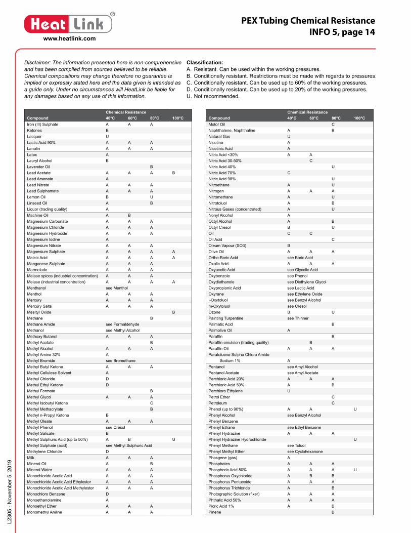
Disclaimer: The information presented here is non-comprehensive and has been compiled from sources believed to be reliable. Chemical compositions may change therefore no guarantee is implied or expressly stated here and the data given is intended as a guide only. Under no circumstances will HeatLink be liable for any damages based on any use of this information.
Classification:A. Resistant. Can be used within the working pressures.B. Conditionally resistant. Restrictions must be made with regards to pressures.C. Conditionally resistant. Can be used up to 60% of the working pressures.D. Conditionally resistant. Can be used up to 20% of the working pressures.U. Not recommended.
Chemical ResistanceCompound 40°C 60°C 80°C 100°CIron (III) Sulphate A A AKetones BLacquer ULactic Acid 90% A A ALanolin A A ALatex ALauryl Alcohol BLavender Oil BLead Acetate A A A BLead Arsenate ALead Nitrate A A ALead Sulphamate A A ALemon Oil B ULinseed Oil A BLiquor (trading quality) AMachine Oil A BMagnesium Carbonate A A AMagnesium Chloride A A AMagnesium Hydroxide A A AMagnesium Iodine AMagnesium Nitrate A A AMagnesium Sulphate A A A AMaleic Acid A A A AManganese Sulphate A A AMarmelade A A AMelase spices (industrial concentration) A A AMelase (industrial concentration) A A A AMenthanol see MentholMenthol A A AMercury A A AMercury Salts A A AMesityl Oxide BMethane BMethane Amide see FormaldehydeMethanol see Methyl AlcoholMethoxy Butanol A A AMethyl Acetate BMethyl Alcohol A A AMethyl Amine 32% AMethyl Bromide see BromethaneMethyl Butyl Ketone A A AMethyl Cellulose Solvent AMethyl Chloride DMethyl Ethyl Ketone DMethyl Formate BMethyl Glycol A A AMethyl Isobutyl Ketone CMethyl Methacrylate BMethyl n-Propyl Ketone BMethyl Oleate A A AMethyl Phenol see CresolMethyl Salicate BMethyl Sulphuric Acid (up to 50%) A B UMethyl Sulphate (acid) see Methyl Sulphuric AcidMethylene Chloride DMilk A A AMineral Oil A BMineral Water A A AMonochloride Acetic Acid A A AMonochloride Acetic Acid Ethylester A A AMonochloride Acetic Acid Methylester A A AMonochloro Benzene DMonoethanolamine AMonoethyl Ether A A AMonomethyl Aniline A A A
Chemical ResistanceCompound 40°C 60°C 80°C 100°CMotor Oil CNaphthalene, Naphthaline A BNatural Gas UNicotine ANicotinic Acid ANitric Acid <30% A ANitric Acid 30-50% CNitric Acid 40% UNitric Acid 70% CNitric Acid 98% UNitroethane A UNitrogen A A ANitromethane A UNitrotoluol A BNitrous Gases (concentrated) A UNonyl Alcohol AOctyl Alcohol A BOctyl Cresol B UOil C COil Acid COleum Vapour (SO3) BOlive Oil A A AOrtho-Boric Acid see Boric AcidOxalic Acid A A AOxyacetic Acid see Glycolic AcidOxybenzole see PhenolOxydiethanole see Diethylene GlycolOxypropionic Acid see Lactic AcidOxyrane see Ethylene Oxidel-Oxytoluol see Benzyl Alcoholm-Oxytoluol see CresolOzone B UPainting Turpentine see ThinnerPalmatic Acid BPalmolive Oil AParaffin BParaffin emulsion (trading quality) BParaffin Oil A A AParatoluene Sulpho Chloro Amide Sodium 1% APentanol see Amyl AlcoholPentanol Acetate see Amyl AcetatePerchloric Acid 20% A A APerchloric Acid 50% A BPerchloro Ethylene UPetrol Ether CPetroleum CPhenol (up to 90%) A A UPhenyl Alcohol see Benzyl AlcoholPhenyl BenzenePhenyl Ethane see Ethyl BenzenePhenyl Hydrazine A A APhenyl Hydrazine Hydrochloride UPhenyl Methane see ToluolPhenyl Methyl Ether see CyclohexanonePhosgene (gas) APhosphates A A APhosphoric Acid 80% A A A UPhosphorus Oxychloride A B BPhosphorus Pentaoxide A A APhosphorus Trichloride A BPhotographic Solution (fixer) A A APhthalic Acid 50% A A APicric Acid 1% A BPinene B

L230
5 - N
ovem
ber 5
, 201
9
www.heatlink.com
®
Heat Link PEX Tubing Chemical ResistanceINFO 5, page 15
Disclaimer: The information presented here is non-comprehensive and has been compiled from sources believed to be reliable. Chemical compositions may change therefore no guarantee is implied or expressly stated here and the data given is intended as a guide only. Under no circumstances will HeatLink be liable for any damages based on any use of this information.
Classification:A. Resistant. Can be used within the working pressures.B. Conditionally resistant. Restrictions must be made with regards to pressures.C. Conditionally resistant. Can be used up to 60% of the working pressures.D. Conditionally resistant. Can be used up to 20% of the working pressures.U. Not recommended.
Chemical ResistanceCompound 40°C 60°C 80°C 100°CPotassium Acetate BPotassium Bichromate 40% see Potassium DichromatePotassium Borate 1% A A APotassium Bromate A A APotassium Bromide A A APotassium Carbonate A A APotassium Chlorate A A APotassium Chloride A A APotassium Chromate A A APotassium Chromium Sulphate A A A BPotassium Cupro Cyanide A A APotassium Cyanide A A APotassium Dichromate 40% A A APotassium Ferricyanide A A A BPotassium Fluoride A A APotassium Hydrogen Carbonate A A APotassium Hydrogen Sulphate A A APotassium Hydrogen Sulphite Solution A A APotassium Hydroxide 50% UPotassium Hydroxide 60% A A APotassium Hypochlorite Solution A BPotassium Iodide (cold saturated) A A APotassium Nitrate A A APotassium Orthophosphate A A APotassium Perborate A A APotassium Perchlorate 1% A A A APotassium Perchlorate 10% APotassium Permanganate 18% A A APotassium Phosphate A A APotassium Sulphate A A APotassium Sulphate (cold saturated) A A APotassium Sulphide A A APotassium Sulphite APotassium Supersulphate A A A UPseudo Cumol A A APropane Acid see Propionic AcidPropane Diol see Propylene GlycolPropane Triol see GlycerinePropane (gas) APropane (liquid) BPropanol A A APropanone see AcetonePropene A A APropionic Acid A A APropyl Acetate BPropyl Alcohol see PropanolPropylene Dichloriole UPropylene Glycol A A APropylene Oxide APyridine CPyrol BResorcinol ARicine Oil A BRinser Loosener A A ARoad Tar USalicylic Acid A A ASelenic Acid ASilicone Fats A A ASilicone Oils A A ASilver Nitrate <80% A A A BSilver Salts (cold saturated) A A ASoap A A ASoap Loosener A A ASoap Solution A A ASoda see Sodium Carbonate
Chemical ResistanceCompound 40°C 60°C 80°C 100°CSodium Acetate A A ASodium Aluminate A A ASodium Benzoate A A ASodium Benzoate (up to 36%) A A ASodium Bicarbonate A A ASodium Bisulphate A A ASodium Bisulphite A A A ASodium Borate A A ASodium Bromide A A ASodium Carbonate A A ASodium Chlorate A A ASodium Chloride A A A ASodium Chlorite and Bleach A BSodium Chlorite and Water ASodium Cyanide A A ASodium Ferricyanide A A ASodium Ferrocyanide A A ASodium Fluoride A A ASodium Hydrogen Carbonate A A ASodium Hydrogen Phosphate A A ASodium Hydrogen Sulphite Solution A A ASodium Hydrosulphite 10% A A ASodium Hydroxide A A ASodium Hypochlorite A A ASodium HyposulphateSodium Metaphosphate A A ASodium Nitrate A A ASodium Nitrite A A ASodium Perborate A A ASodium Peroxide A A ASodium Phosphate A A ASodium Polycrylate (GR 894) A A ASodium Silicate A A ASodium Sulphate A A ASodium Sulphide A A ASodium Sulphite A A ASodium Tetraborate A A ASodium Thiosulphate A A ASoya Oil ASpinning Oil A BSpinning Bath Oil Containing Carbon Disulphide 0.01% A ASpinning Bath Oil Containing Carbon Disulphide 0.07% A ASpot Solvents A A AStarch A A AStarch Syrup A A A AStearic Acid BSucrose Solution A A ASulphur A A ASulphur Dioxide (dry) A A A BSulphur Dioxide (in water solution) A A ASulphur Solution ASulphur Trioxide CSulphuric Acid <50% A A ASulphuric Acid 70% A CSulphuric Acid 80-90% CSulphuric Acid 96% CSulphuryl Chloride BSuperchloric Acid see Perchloric AcidSynthetic Washing Powder (home quality) A A ATannin see Ascorbic Acid Tar UTertiary Butyl Alcohol A A A
L230
5 - N
ovem
ber 5
, 201
9
www.heatlink.com
®
Heat Link PEX Tubing Chemical ResistanceINFO 5, page 16
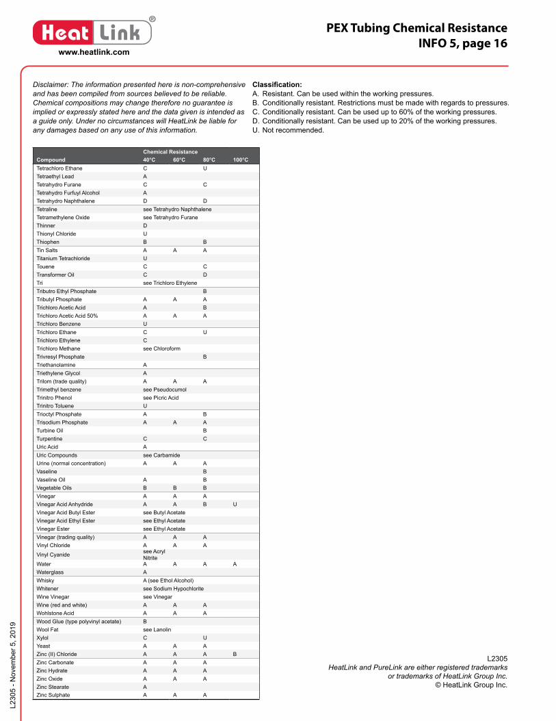
Disclaimer: The information presented here is non-comprehensive and has been compiled from sources believed to be reliable. Chemical compositions may change therefore no guarantee is implied or expressly stated here and the data given is intended as a guide only. Under no circumstances will HeatLink be liable for any damages based on any use of this information.
Classification:A. Resistant. Can be used within the working pressures.B. Conditionally resistant. Restrictions must be made with regards to pressures.C. Conditionally resistant. Can be used up to 60% of the working pressures.D. Conditionally resistant. Can be used up to 20% of the working pressures.U. Not recommended.
Chemical ResistanceCompound 40°C 60°C 80°C 100°CTetrachloro Ethane C UTetraethyl Lead ATetrahydro Furane C CTetrahydro Furfuyl Alcohol ATetrahydro Naphthalene D DTetraline see Tetrahydro NaphthaleneTetramethylene Oxide see Tetrahydro FuraneThinner DThionyl Chloride UThiophen B BTin Salts A A ATitanium Tetrachloride UTouene C CTransformer Oil C DTri see Trichloro EthyleneTributro Ethyl Phosphate BTributyl Phosphate A A ATrichloro Acetic Acid A BTrichloro Acetic Acid 50% A A ATrichloro Benzene UTrichloro Ethane C UTrichloro Ethylene CTrichloro Methane see ChloroformTrivresyl Phosphate BTriethanolamine ATriethylene Glycol ATrilom (trade quality) A A ATrimethyl benzene see PseudocumolTrinitro Phenol see Picric AcidTrinitro Toluene UTrioctyl Phosphate A BTrisodium Phosphate A A ATurbine Oil BTurpentine C CUric Acid AUric Compounds see CarbamideUrine (normal concentration) A A AVaseline BVaseline Oil A BVegetable Oils B B BVinegar A A AVinegar Acid Anhydride A A B UVinegar Acid Butyl Ester see Butyl AcetateVinegar Acid Ethyl Ester see Ethyl AcetateVinegar Ester see Ethyl AcetateVinegar (trading quality) A A AVinyl Chloride A A A
Vinyl Cyanide see Acryl Nitrite
Water A A A AWaterglass AWhisky A (see Ethol Alcohol)Whitener see Sodium HypochloriteWine Vinegar see VinegarWine (red and white) A A AWohlstone Acid A A AWood Glue (type polyvinyl acetate) BWool Fat see LanolinXylol C UYeast A A AZinc (II) Chloride A A A BZinc Carbonate A A AZinc Hydrate A A AZinc Oxide A A AZinc Stearate AZinc Sulphate A A A
L2305HeatLink and PureLink are either registered trademarks
or trademarks of HeatLink Group Inc.© HeatLink Group Inc.