Embed Size (px)
Citation preview
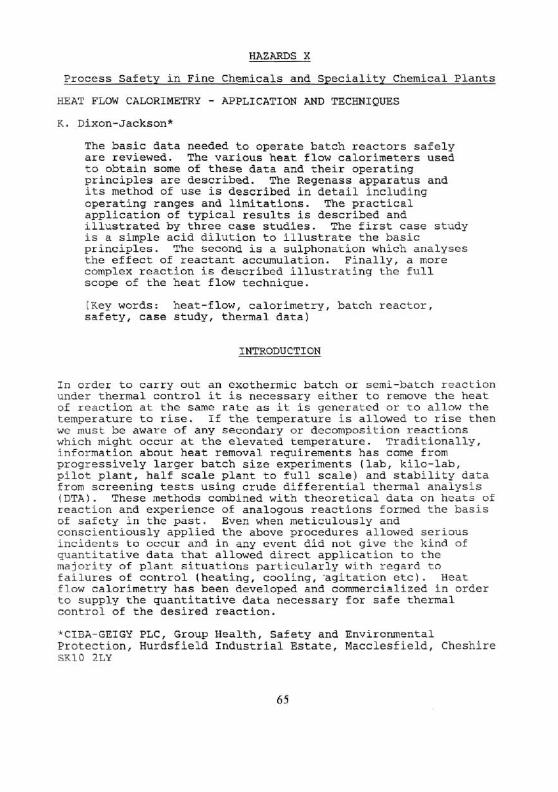
HAZARDS X
Process Safety in Fine Chemicals and Speciality Chemical Plants
HEAT FLOW CALORIMETRY - APPLICATION AND TECHNIQUES
K. Dixon-Jackson*
The basic data needed to operate batch reactors safely are reviewed. The various heat flow calorimeters used to obtain some of these data and their operating principles are described. The Regenass apparatus and its method of use is described in detail including operating ranges and limitations. The practical application of typical results is described and illustrated by three case studies. The first case study is a simple acid dilution to illustrate the basic principles. The second is a sulphonation which analyses the effect of reactant accumulation. Finally, a more complex reaction is described illustrating the full scope of the heat flow technique.
(Key words: heat-flow, calorimetry, batch reactor, safety, case study, thermal data)
INTRODUCTION
In order to carry out an exothermic batch or semi-batch reaction under thermal control it is necessary either to remove the heat of reaction at the same rate as it is generated or to allow the temperature to rise. If the temperature is allowed to rise then we must be aware of any secondary or decomposition reactions which might occur at the elevated temperature. Traditionally, information about heat removal requirements has come from progressively larger batch size experiments (lab, kilo-lab, pilot plant, half scale plant to full scale) and stability data from screening tests using crude differential thermal analysis (DTA). These methods combined with theoretical data on heats of reaction and experience of analogous reactions formed the basis of safety in the past. Even when meticulously and conscientiously applied the above procedures allowed serious incidents to occur and in any event did not give the kind of quantitative data that allowed direct application to the majority of plant situations particularly with regard to failures of control (heating, cooling, agitation etc). Heat flow calorimetry has been developed and commercialized in order to supply the quantitative data necessary for safe thermal control of the desired reaction.
*CIBA-GEIGY PLC, Group Health, Safety and Environmental Protection, Hurdsfield Industrial Estate, Macclesfield, Cheshire SK10 2LY
61
IChemE SYMPOSIUM SERIES No. 115
1. Bas i c Data
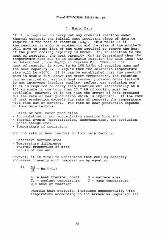
If it is required to carry out any chemical reaction under thermal control, the initial most important piece of data we require is the heat of reaction (AHR). This tells us if the reaction is endo or exothermic and the size of the exotherm will give us some idea of the time required to remove the heat if the plant cooling capacity is known. If, in addition to the heat of reaction, the heat capacity (Cp) is determined then the temperature rise due to an adiabatic reaction (no heat loss) can be determined [from AHR/Cp in degrees C]. Thus, if the heat of reaction is known to be 100 kJ/kg of reaction mass and the heat capacity 2.0 kJ/kg/°C then the adiabatic temperature rise will be +50°C. If it can be established that the reaction mass is stable 50°C above the start temperature, the reaction can be carried out without heat removal provided other factors do not intervene (product quality, reflux, gas evolution etc). If it is required to carry this reaction out isothermally on a 100 kg scale in one hour then 27.7 kw of cooling must be available. However, it is not just the amount of heat produced but the rate of heat production which is important. If the rate of heat production exceeds the rate of removal, the temperature will rise out of control. The rate of heat production depends on four main factors:
- Batch or semi-batch production - Accumulative or non accumulative reaction kinetics - Thermal events (precipitation, decomposition, gas evolution, phase-change etc)
- Temperature of operations
and the rate of heat removal on four main factors:
- Effective surface area - Temperature difference - Thermal properties of mass - Nature of coolant.
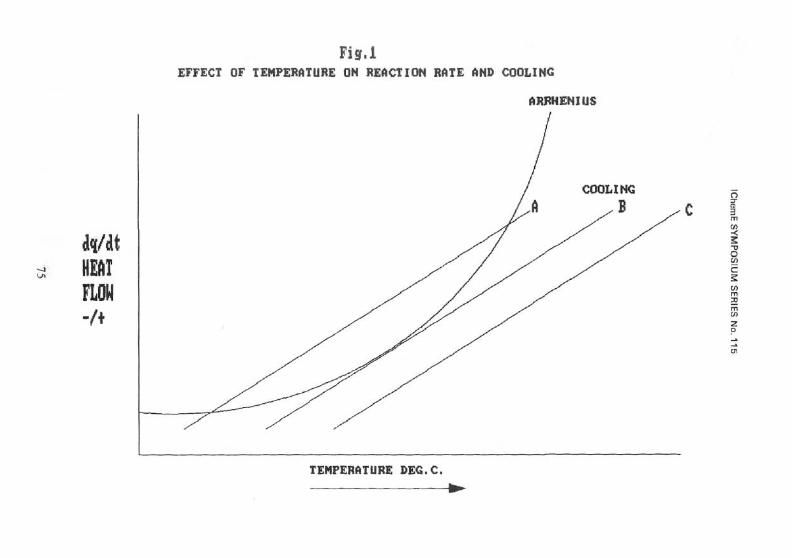
However, it is vital to understand that cooling capacity increases linearly with temperature by equation
i} g = hs( T- T A) h = heat transfer coeff S = surface area TA = coolant temperature T = mass temperature Q,= heat of reaction
whereas heat evolution increases exponentially with temperature acccording to the Arrhenius (equation ii)
66
IChemE SYMPOSIUM SERIES No. 115
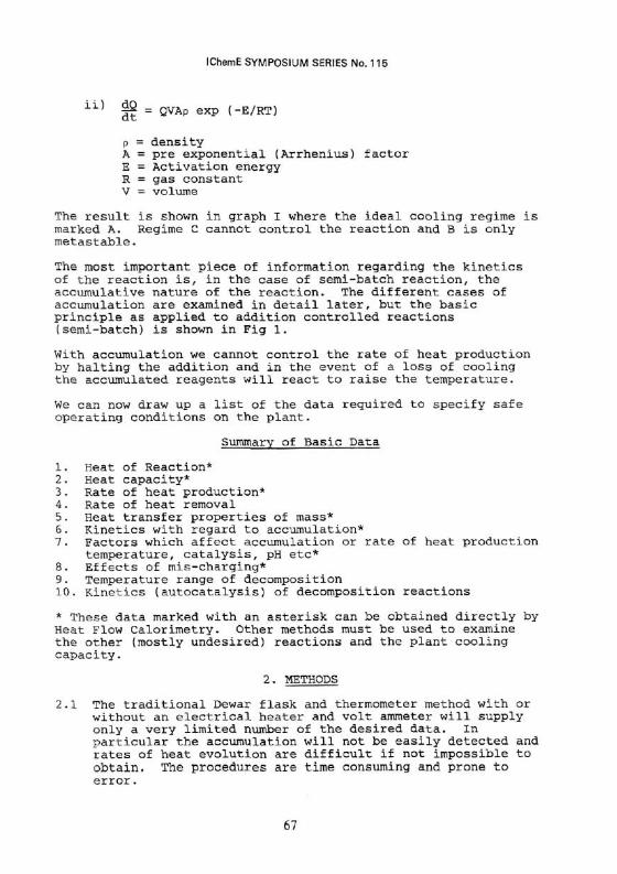
1 1 ] |2 = QVAp exp (-E/RT)
p = density A = pre exponential (Arrhenius) factor E = Activation energy R = gas constant V = volume
The result is shown in graph I where the ideal cooling regime is marked A. Regime C cannot control the reaction and B is only metastable.
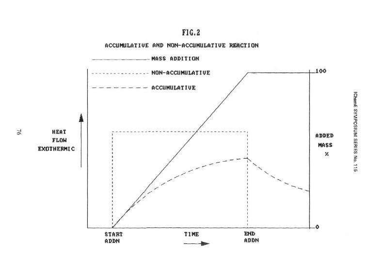
The most important piece of information regarding the kinetics of the reaction is, in the case of semi-batch reaction, the accumulative nature of the reaction. The different cases of accumulation are examined in detail later, but the basic principle as applied to addition controlled reactions (semi-batch) is shown in Fig 1.
With accumulation we cannot control the rate of heat production by halting the addition and in the event of a loss of cooling the accumulated reagents will react to raise the temperature.
We can now draw up a list of the data required to specify safe operating conditions on the plant.
Summary of Basic Data
1. Heat of Reaction* 2. Heat capacity* 3. Rate of heat production* 4. Rate of heat removal 5. Heat transfer properties of mass* 6. Kinetics with regard to accumulation* 7. Factors which affect accumulation or rate of heat production
temperature, catalysis, pH etc* 8. Effects of mis-charging* 9. Temperature range of decomposition 10. Kinetics (autocatalysis) of decomposition reactions
* These data marked with an asterisk can be obtained directly by Heat Flow Calorimetry. Other methods must be used to examine the other (mostly undesired) reactions and the plant cooling capacity.
2. METHODS
2.1 The traditional Dewar flask and thermometer method with or without an electrical heater and volt ammeter will supply only a very limited number of the desired data. In particular the accumulation will not be easily detected and rates of heat evolution are difficult if not impossible to obtain. The procedures are time consuming and prone to error.
67
IChemE SYMPOSIUM SERIES No. 115
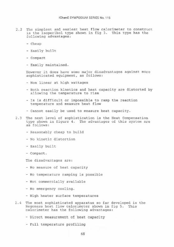
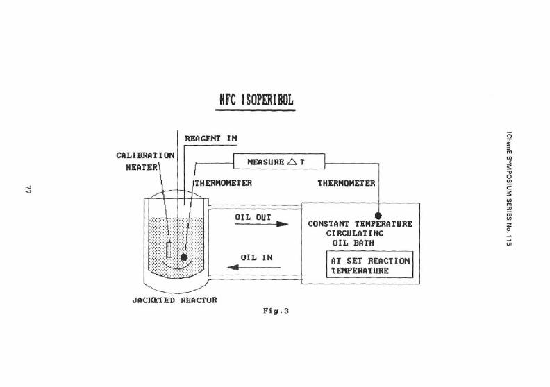
2 The simplest and easiest heat flow calorimeter to construct is the Isoperibol type shown in fig 3. This type has the following advantages:
- Cheap
- Easily built
- Compact
- Easily maintained.
However it does have some major disadvantages against more sophisticated equipment, as follows:
- Non linear at high wattages
- Both reaction kinetics and heat capacity are distorted by allowing the temperature to rise
- Is is difficult or impossible to ramp the reaction temperature and measure heat flow
- Cannot easily be used to measure heat capacity.
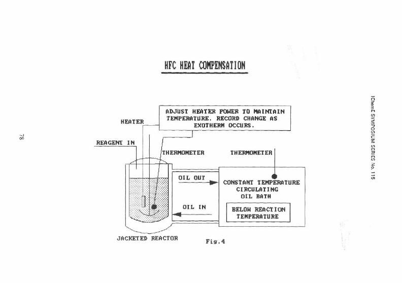
3 The next level of sophistication is the Heat Compensation type shown in figure 4. The advantages of this system are as follows:
- Reasonably cheap to build
- No kinetic distortion
- Easily built
- Compact.
The disadvantages are:
- No measure of heat capacity
- No temperature ramping is possible
- Not commercially available
- No emergency cooling.
- High heater surface temperatures
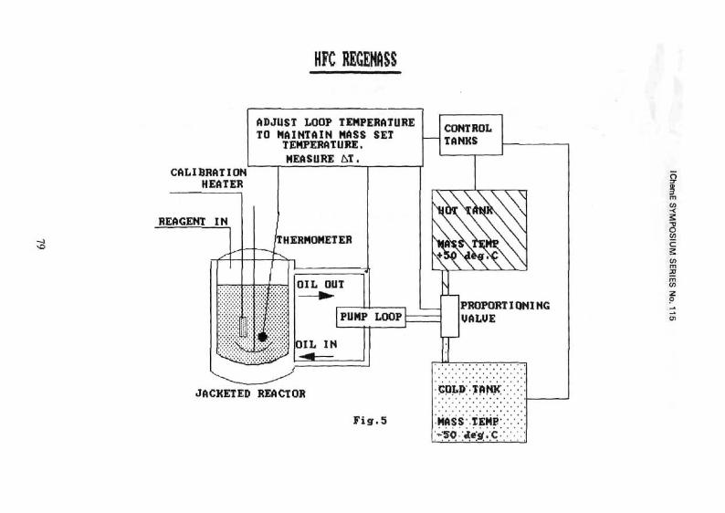
4 The most sophisticated apparatus so far developed is the Regenass heat flow calorimeter shown in fig 5. This calorimeter has the following advantages:
- Direct measurement of heat capacity
- Full temperature profiling
IChemE SYMPOSIUM SERIES No. 115
- No kinetic distortion
- Wide wattage range +ve and -ve
- High level of safety interlocks
- Commercially available
- Wide range of ancillaries available.
The advanced design and ease of use of this machine mean that its two disadvantages are:
- Cost
- Relatively large size.
Whichever heat flow calorimeter is chosen, they all share the following limitations:
- They only work with reasonably mobile systems (liguids and suspensions)
- Reflux must be suppressed by application of pressure (usually N2)
- Strongly alkaline or HF solutions are not compatible with glass reactors
- These systems are not suitable for the determination of heats of decomposition.
3. INTERPRETATION AND USE
The Regenass calorimeter is probably the most popular heat flow calorimeter in use today. There are at least 7 in use in the UK at the time of writing and scores are in use worldwide. The basic principle is shown in fig. 5 where the difference between the temperature of the heat transfer medium and the mass temperature is a direct and linear measure of the heat-flow (wattage). (Fuller treatments are also given in the literature references (1), (2), (3), (4) and (5)).
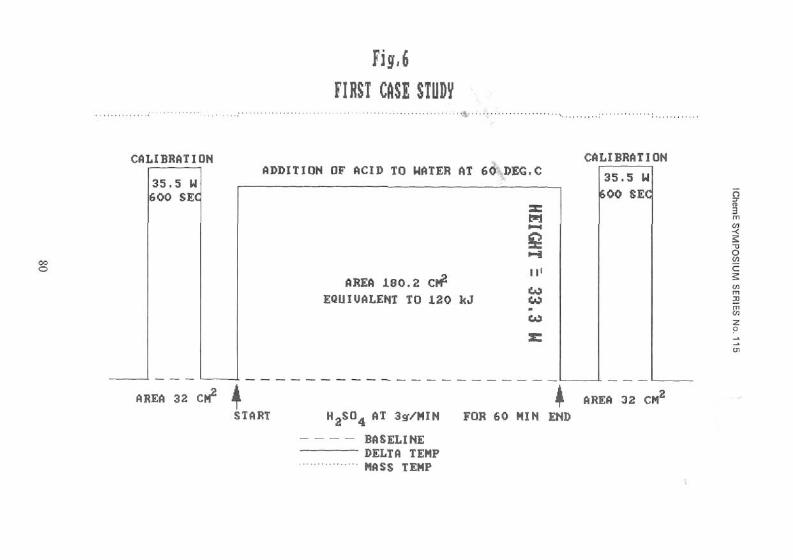
The example shown in fig 6 is a case study of a simple acid dilution. The values given are real and have been used to cross-calibrate calorimeters of different types. The reaction conditions are as follows:
1100 g of water at 60°C in reactor 180 g of H2S04 98.07%.
Addition rate 3.0 g/min over one hour with the acid at 25°C. Interpretation is extremely simple. The reaction area is related to the calibration areas at the start and end of the reaction to obtain the heat of reaction. The
69
IChemE SYMPOSIUM SERIES No. 115
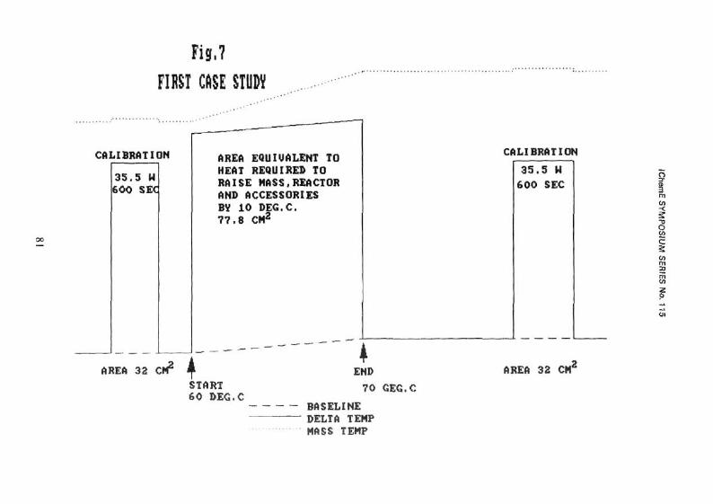
height of the reaction trace is related to the height of the calibration to give the wattage at any stage. The usual result for this reaction is 116 kJ ±5%. The corresponding wattage is therefore ca 33 W. In fig 7 the heat capacity is determined by measuring the heat required to ramp the mass temperature over a known range. Once the heat capacity of the reactor and its accessories (agitator, calibrator etc) have been found using a known liquid (water), this can be subtracted from the total heat to give an exact value.
Using the figures 6 and 7 the following data for this simple reaction can be calculated:
Heat of Reaction
35.5 W for 600 seconds is 21.3 kJ
21.3 kJ is 32 cm2 at 60°C and 70°C
Reaction area 180.2 cm2 = 1119.9 kJ
Mass at end of reaction is
1100 + 180 = 1280 g
so heat of reaction 93.7 kJ/kg
Rate of Heat Production
35.5 W gives 8.0 cm vertical displacement
Reaction gives 7.25 cm
so reaction wattage is
35.5 x 8_ = 32.8 W, or 25.6 W/kg. 7.25
Heat Capacity
The area required to ramp mass, reactor etc by 10°C
was 47.8 cm2.
As 21.3 kJ = 32 cm2
this represents a heat requirement of 51.78 kJ.
However, a previous calibration has shown the reactor, etc, to have a water equivalent of 100 g.
Thus 100 x 4.186 x 10 J were used to heat the reaction etc.
70
IChemE SYMPOSIUM SERIES No. 115
The heat required for the mass alone is
51.78-4.19 or 47.6 kJ.
This gives a heat capacity of 47.6/1.280/10 or 3.7 kJ/kg°K (specific heat 0.89).
Application
i) If this process were to be carried out on a 1000 times scale then the reactor system would need to have a total cooling capacity of 25.6 kW
ii) If cooling is not applied the mass will heat up by 93.7/3.7 = +25.3°C (from 60 to 85.3°C) irrespective of the scale
iii) As the rate of heat production was directly proportional to the rate of addition of H2S04, heat output can be controlled by the rate of addition of HzSOi on the plant.
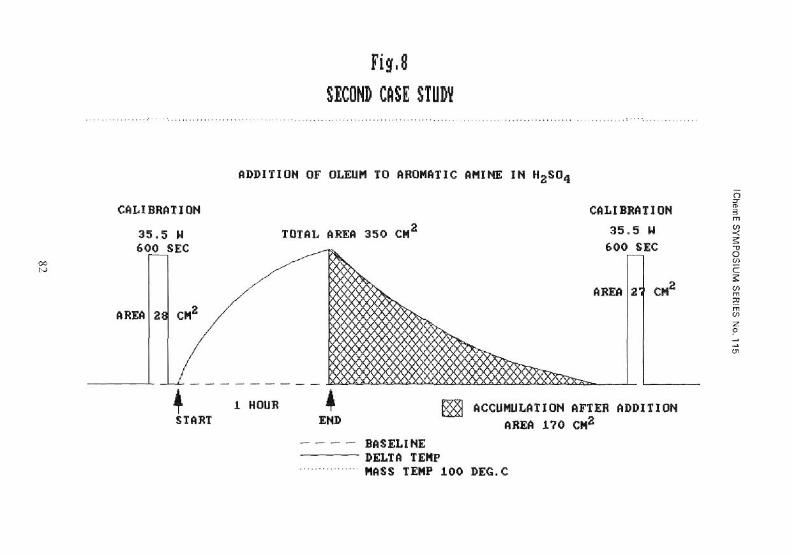
3.3 The example shown in fig 8 is the second case study where an aromatic amine is being sulphonated.
The aromatic amine 520 g in 800 g of H2S04 was held at 100°C and 560 g of Oleum 65% was added over 1 hour. The normal data can be obtained as shown above.
Heat of Reaction 144.2 kJ/kg [Calculated elsewhere, Heat Capacity 1.38 kJ/kg°K] Maximum wattage 200 W/kg Adiabatic temperature rise +104°C from 100°C gives a final mass temperature 204°C.
This reaction cannot be done adiabatically because a violent exothermic decomposition occurs at temperatures in excess of 150°C. But of even more significance is the shaded area due to accumulation of unreacted Oleum. There is sufficient heat of accumulation to raise the mass by +52°c to 152°C and induce the violent decomposition. The mass at the end of the 1 hour oleum addition is unstable and any loss of control will lead to a violent decomposition. The practical implications are that changes must be made to the reaction conditions (increase the addition time, increase the reaction temperature, or dilute in more H2SO«) such that the accumulation can never raise the mass temperature to a dangerous region. As an alternative, elaborate and fail-safe controls could be installed to render the mass safe (drown-out, dilution or emergency cooling/agitation). In practice it was found that addition of Oleum over 8 hours at 110°C reduced the accumulation to an adiabatic temperature rise of +6°C. (Final mass temperature 116°C). Kinetic studies of the decomposition showed that at 120°C at least 48 hours were available for remedial action to be taken to avoid a violent decomposition.
71
IChemE SYMPOSIUM SERIES No. 115
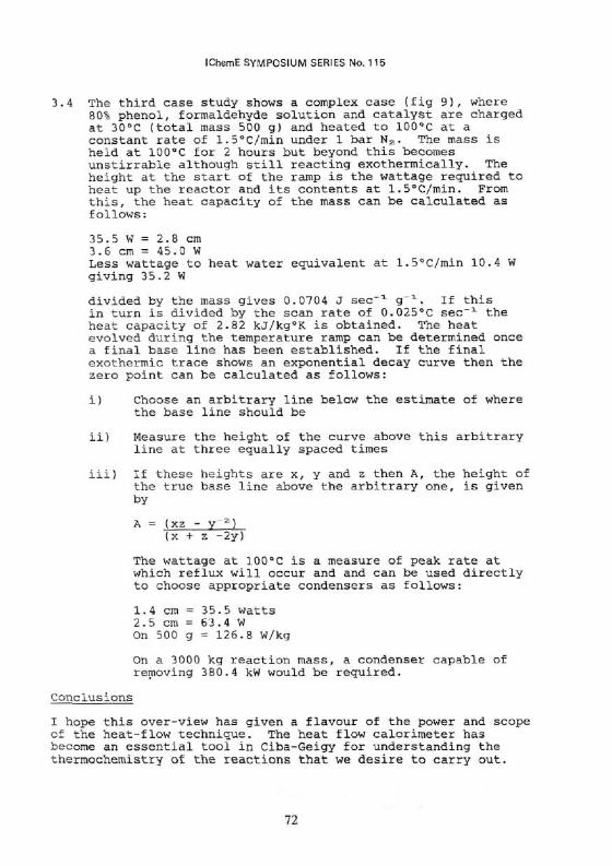
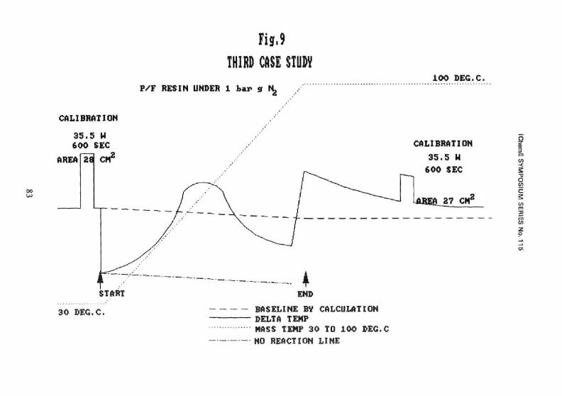
3.4 The third case study shows a complex case (fig 9), where 80% phenol, formaldehyde solution and catalyst are charged at 30°C (total mass 500 g) and heated to 100°C at a constant rate of 1.5°C/min under 1 bar N2. The mass is held at 100°C for 2 hours but beyond this becomes unstirrable although still reacting exothermically. The height at the start of the ramp is the wattage required to heat up the reactor and its contents at 1.5°C/min. From this, the heat capacity of the mass can be calculated as follows:
35.5 W = 2.8 cm 3.6 cm = 45.0 W Less wattage to heat water equivalent at 1.5°C/min 10.4 W giving 35.2 W
divided by the mass gives 0.0704 J sec-1 g_i. If this in turn is divided by the scan rate of 0.025°C sec-1 the heat capacity of 2.82 kJ/kg°K is obtained. The heat evolved during the temperature ramp can be determined once a final base line has been established. If the final exothermic trace shows an exponential decay curve then the zero point can be calculated as follows:
i) Choose an arbitrary line below the estimate of where the base line should be
ii) Measure the height of the curve above this arbitrary line at three equally spaced times
iii) If these heights are x, y and z then A, the height of the true base line above the arbitrary one, is given by
A = (xz - y 2 ) (x + z -2y)
The wattage at 100°C is a measure of peak rate at which reflux will occur and and can be used directly to choose appropriate condensers as follows:
1.4 cm = 35.5 watts 2.5 cm = 63.4 W On 500 g = 126.8 W/kg
On a 3000 kg reaction mass, a condenser capable of removing 380.4 kW would be required.
Conclusions
I hope this over-view has given a flavour of the power and scope of the heat-flow technique. The heat flow calorimeter has become an essential tool in Ciba-Geigy for understanding the thermochemistry of the reactions that we desire to carry out.
72

IChemE SYMPOSIUM SERIES No. 115
This power derives from the fact that in concept, the equipment mimics a successful plant reactor under temperature control (either via cooling or at reflux) which is how we carry out over 90% of our reactions. Neither scanning or adiabatic calorimeters meet this fundamental requirement. By concentrating here on the safety-related matters, the benefits of heat flow calorimetry in terms of process optimization, understanding and development have been understated but more and more instruments are being installed for just these purposes throughout the world.
73
IChemE SYMPOSIUM SERIES No. 115
REFERENCES
1. Regenass, W et al, 1974, Proc 4th Int Conf Thermal Anal, 3_/ 834, Budapest
2. Regenass, W, 1980, Proc 6th Int Conf Thermal Anal, 1, 561 Bagreuth
3. Regenass, W, 1977, Thermochim Acta, 2_0, 65
4. Regenass, W, 1978, ACS Symp Ser 65, 37
5. Brogli, F, et al, 1981, I Chem E Symp Series No 68, 3/Ml... 3/M10
74
IChem
E S
YM
PO
SIU
M S
ER
IES
No. 115
75
IChem
E S
YM
PO
SIU
M S
ER
IES
No. 115
76
IChem
E S
YM
PO
SIU
M S
ER
IES
No. 115
77
IChem
E S
YM
PO
SIU
M S
ER
IES
No. 115
78
IChem
E S
YM
PO
SIU
M S
ER
IES
No. 115
79
IChem
E S
YM
PO
SIU
M S
ER
IES
No. 115
m
3 °
JO
»
\0
O
6 w
A
©
SO
HEIG
HT
1 I 1
= 3
3.3 U
u
M
<x
fa
z w
o so
80
r o *-« H
> a x m
H
« a w
Hi
« z o
Hi
a *-> o
<c fa o
z o
1-4
Hi
H*
o
ft a *H
in
" .-
©
H2 ©
f ^D
<z u
N
©
05
H
<X
•1
face •̂
X
1
04
W
1
o
I H
H
Z
1 W
^
1 <x =
• j
HH
=3 fa
| i 1 1 1 1
K
O
fa
V
CO
Hi
•CC
a H
CC
<x H
-C
O
fa Z
fa
MU
Z
Z
Hi W
H
H
Hi
-J
<X
WH
« (A
»4 (A
«
fa <C
m
« z
o
•NS
PS
a fa fa <r
IChem
E S
YM
PO
SIU
M S
ER
IES
No. 1
15
81
IChem
E S
YM
PO
SIU
M S
ER
IES
No. 115
82
IChem
E S
YM
PO
SIU
M S
ER
IES
No. 115