Embed Size (px)
Citation preview
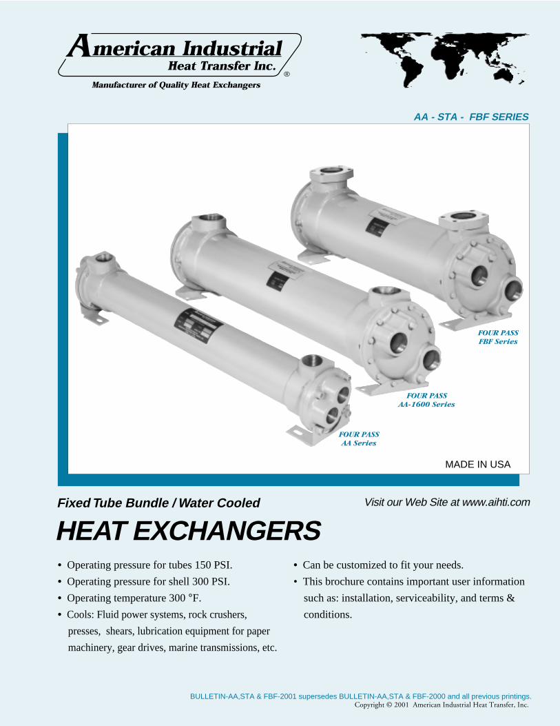
Fixed Tube Bundle / Water Cooled
HEAT EXCHANGERS• Operating pressure for tubes 150 PSI.
• Operating pressure for shell 300 PSI.
• Operating temperature 300 °F.
• Cools: Fluid power systems, rock crushers,
presses, shears, lubrication equipment for paper
machinery, gear drives, marine transmissions, etc.
AA - STA - FBF SERIES
• Can be customized to fit your needs.
• This brochure contains important user information
such as: installation, serviceability, and terms &
conditions.
FOUR PASSAA Series
FOUR PASSAA-1600 Series
FOUR PASSFBF Series
®
Visit our Web Site at www.aihti.com
MADE IN USA
Copyright © 2001 American Industrial Heat Transfer, Inc.BULLETIN-AA,STA & FBF-2001 supersedes BULLETIN-AA,STA & FBF-2000 and all previous printings.

Copyright © 2001 American Industrial Heat Transfer, Inc.
AA SERIES: used when non ferrous materials arerequired.
Fixed tube construction heat exchangers with NPT con-
nections are made of brass with copper tubing and cast iron
end bonnets. Sizes from 2" through 10" diameters, and from
1.4 to 540 sq.ft. Standard one, two, or four pass models are
available. Options include 90/10 copper nickel and 316 stain-
less steel tube, bronze bonnets and zinc anodes. Can be cus-
tomized to fit your requirements.
Commonly used for water processing, chillers, hydraulic
systems, lubrication oils, etc…
FBF SERIES: used when non ferrous materials arerequired.
Fixed tube construction heat exchangers with SAE O-
Ring or Four bolt flanges, made of brass with copper tubing
and cast iron end bonnets. Sizes from 2" through 10" diam-
eters, and from 1.4 to 540 sq.ft. Standard one, two or four
pass models are available. Options include 90/10 copper
nickel and 316 stainless steel tube, bronze bonnets and zinc
anodes. Can be customized to fit your requirements.
Commonly used in automotive plants, hydraulic power
units, oil processing, etc…
STA SERIES: used in applications requiringstainless steel construction.
Fixed tube construction heat exchangers are made of 316
stainless steel. Sizes from 2" through 10" diameters, and from
1.4 to 540 sq.ft. Standard one, two or four pass models are
available. Options include Viton, Teflon, EPR, Buna, and
Kalrez seals. Can be customized to fit your requirements.
Commonly used for chemical processing, food process-
ing, military systems, medical equipment, etc…
INTRODUCTION
2
Copyright © 2001 American Industrial Heat Transfer, Inc.
STANDARD CONSTRUCTION MATERIALS & RATINGS
Shell
Tubes
Baffle
Integral End Hub
End Bonnets
Mounting Brackets
Gasket
Flanges
AA Series STA Series FBF SeriesStandard Model
Brass
Copper
Brass
Forged Brass
Cast Iron
Steel
Hypalon Composite
-
316 Stainless Steel
316 Stainless Steel
316 Stainless Steel
316 Stainless Steel
316 Stainless Steel
Steel
Hypalon Composite
-
Brass
Copper
Brass
Forged Brass
Cast Iron
Steel
Hypalon Composite
Steel
Standard Unit Ratings
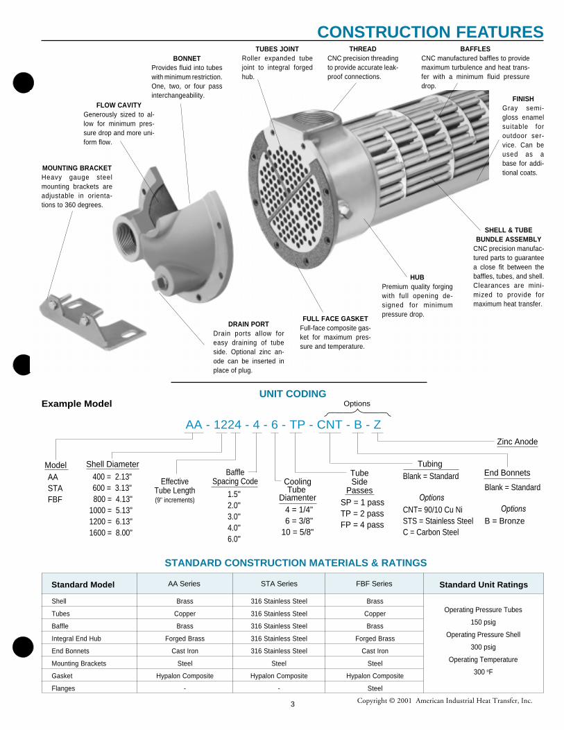
UNIT CODINGExample Model
AA - 1224 - 4 - 6 - TP - CNT - B - Z
Model Shell Diameter
EffectiveTube Length(9" increments)
TubeSide
Passes
AASTAFBF
BaffleSpacing Code
1.5"2.0" 3.0"4.0"6.0"
400 = 2.13"600 = 3.13"
800 = 4.13"1000 = 5.13" 1200 = 6.13"1600 = 8.00"
CoolingTube
Diamenter4 = 1/4"6 = 3/8"
10 = 5/8"
End Bonnets
Blank = Standard Options
B = Bronze
TubingBlank = Standard Options
CNT= 90/10 Cu NiSTS = Stainless SteelC = Carbon Steel
SP = 1 passTP = 2 passFP = 4 pass
Zinc Anode
Options
MOUNTING BRACKETHeavy gauge steelmounting brackets areadjustable in orienta-tions to 360 degrees.
BONNETProvides fluid into tubeswith minimum restriction.One, two, or four passinterchangeability.
TUBES JOINTRoller expanded tubejoint to integral forgedhub.
THREADCNC precision threadingto provide accurate leak-proof connections.
BAFFLESCNC manufactured baffles to providemaximum turbulence and heat trans-fer with a minimum fluid pressuredrop.
FINISHGray semi-gloss enamelsuitable foroutdoor ser-vice. Can beused as abase for addi-tional coats.
SHELL & TUBEBUNDLE ASSEMBLY
CNC precision manufac-tured parts to guaranteea close fit between thebaffles, tubes, and shell.Clearances are mini-mized to provide formaximum heat transfer.
FULL FACE GASKETFull-face composite gas-ket for maximum pres-sure and temperature.
FLOW CAVITYGenerously sized to al-low for minimum pres-sure drop and more uni-form flow.
DRAIN PORTDrain ports allow foreasy draining of tubeside. Optional zinc an-ode can be inserted inplace of plug.
HUBPremium quality forgingwith full opening de-signed for minimumpressure drop.
Operating Pressure Tubes
150 psig
Operating Pressure Shell
300 psig
Operating Temperature
300 oF
CONSTRUCTION FEATURES
3

Copyright © 2001 American Industrial Heat Transfer, Inc.
STEP 1: Calculate the heat load
The heat load in BTU/HR or (Q) can be derived by using several methods. To simplify things, we will consider general specifications forhydraulic system oils and other fluids that are commonly used with shell & tube heat exchangers.
For example purposes, a hydraulic system has a 125 HP (93Kw) electric motor installed coupled to a pump that produces a flow of 80 GPM @2500 PSIG. The temperature differential of the oil entering the pump vs exiting the system is about 5.3°F. Even though our return line pressureoperates below 100 psi, we must calculate the system heat load potential (Q) based upon the prime movers (pump) capability. We can use oneof the following equations to accomplish this:
To derive the required heat load (Q) to be removed by the heat exchanger, apply ONE of the following. Note: The calculated heat loads maydiffer slightly from one formula to the next. This is due to assumptions made when estimating heat removal requirements. The factor (v)represents the percentage of the overall input energy to be rejected by the heat exchanger. The (v) factor is generally about 30% for mosthydraulic systems, however it can range from 20%-70% depending upon the installed system components and heat being generated (ie. servovalves, proportional valves, etc…will increase the percentage required).
STEP 2: Calculate the Mean Temperature Difference
When calculating the MTD you will be required to choose a liquid flow rate to derive the cold side ∆T. If your water flow is unknown you mayneed to assume a number based on what is available. As a normal rule of thumb, for oil to water cooling a 2:1 oil to water ratio is used. Forapplications of water to water or 50 % Ethylene Glycol to water, a 1:1 ratio is common.
Tin
= Ho t Fluid entering temperature in degrees F Tin
= 125.3 °FTout = Ho t Fluid exiting temperature in degrees F T
out= 120.0 °F
tin
= Cold Fluid entering temperature in degrees F tin
= 70.0 °Ftout = Cold Fluid exiting temperature in degrees F t
out= 74.5 °F
Tout - t in S[smaller temperature difference] S 120.0°F -70.0°F = 50.0°F =
50.0°F = .984
Tin -
t
out
= L [larger temperature difference]
= L 125.3°F -74.5°F = 50.8°F 50.8°F
STEP 3: Calculate Log Mean Temperature Difference (LMTD)
To calculate the LMTD please use the following method;
L = Larger temperature difference from step 2.M = S/L number (LOCATED IN TABLE A).
LMTDi = L x M LMTD
i = 50.8 x .992 (FROM TABLE A) = 50.39
To correct the LMTDi for a multipass heat exchangers calculate R & K as follows:
TermsGPM = Gallons Per MinuteCN = Constant Number for a given fluid∆T = Temperature differential across the potentialPSI = Pounds per Square Inch (pressure) of the operating side of the systemMHP = Horsepower of the electric motor driving the hydraulic pump
Kw = Kilowatt (watts x 1000)T
in= Hot fluid entering temperature in °F
T out
= Hot fluid exiting temperature in °Ft
in= Cold fluid temperature entering in °F
t out
= Cold fluid temperature exiting in °FQ = BTU / HR
FORMULA
HOT FLUID ∆T = Q Oil CN x GPM
COLD FLUID ∆ t = BTU / hr Water CN x GPM
EXAMPLE
∆T = 89,090 BTU/hr (from step 1,item B) = 5.3°F = ∆T Rejected210 CN x 80GPM
∆ t = 89,090 BTU/hr = 4.45°F = ∆T Absorbed500 CN x 40GPM (for a 2:1 ratio)
( )
Locate the correction factor CFB
(FROM TABLE B)LMTD
c =LMTD
i x CF
B
LMTDc = 50.39 x 1 = 50.39
Constant for a given fluid ( CN )
1) Oil ..............................CN = 2102) Water .........................CN = 5003) 50% E. Glycol ...........CN = 450
FORMULA
A) Q = GPM x CN x actual ∆TB) Q = [ (PSI x GPM) / 1714 ] x (v ) x 2545C) Q = MHP x (v ) x 2545D) Q = Kw to be removed x 3415E) Q = HP to be removed x 2545
EXAMPLE
A) Q =80 x 210 x 5.3°F = 89,040 BTU/HR
B) Q =[(2500x80)/1714] x .30 x 2545 = 89,090 BTU/HR
C) Q =125 x .30 x 2545 = 95,347 BTU/HR
D) Q =28 x 3415 = 95,620 BTU/HR
E) Q =37.5 x 2545 = 95,437 BTU/HR
FORMULA
R =T
in - T
out
tout
- tin
K =tout
- tin
Tin
- tin
EXAMPLE
R =125.3°F
- 120°F
=5.3°F
= {1.17=R} 74.5°F - 70°F 4.5°F
K = 74.5°F
- 70°F
= 4.5°F
= {0.081=K}124.5°F - 70°F 55.4°F
4
ENGINEERING SELECTION
Copyright © 2001 American Industrial Heat Transfer, Inc.
TABLE A- FACTOR M/LMTD = L x M
TABLE B- LMTD Correction Factor For Multipass Exchangers
TABLE C
TABLE D- Surface Area
TABLE E- Flow Rate for Shell & Tube
.25 .541 .50 .721 .75 .870.01 .215 .26 .549 .51 .728 .76 .864.02 .251 .27 .558 .52 .734 .77 .879.03 .277 .28 .566 .53 .740 .78 .886.04 .298 .29 .574 .54 .746 .79 .890
.05 .317 .30 .582 .55 .753 .80 .896
.06 .334 .31 .589 .56 .759 .81 .902
.07 .350 .32 .597 .57 .765 .82 .907
.08 .364 .33 .604 .58 .771 .83 .913
.09 .378 .34 .612 .59 .777 .84 .918
.10 .391 .35 .619 .60 .783 .85 .923
.11 .403 .36 .626 .61 .789 .86 .928
.12 .415 .37 .634 .62 .795 .87 .934
.13 .427 .38 .641 .63 .801 .88 .939
.14 .438 .39 .648 .64 .806 .89 .944
.15 .448 .40 .655 .65 .813 .90 .949
.16 .458 .41 .662 .66 .818 .91 .955
.17 .469 .42 .669 .67 .823 .92 .959
.18 .478 .43 .675 .68 .829 .93 .964
.19 .488 .44 .682 .69 .836 .94 .970
.20 .497 .45 .689 .70 .840 .95 .975
.21 .506 .46 .695 .71 .848 .96 .979
.22 .515 .47 .702 .72 .852 .97 .986
.23 .524 .48 .709 .73 .658 .98 .991
.24 .533 .49 .715 .74 .864 .99 .995
S/L M S/L M S/L M S/L M
U TUBE FLUID SHELL FLUID
400 Water Water350 Water 50% E. Glycol100 Water Oil300 50% E. Glycol 50% E. Glycol90 50% E. Glycol Oil
AA-1224 – 23.6 11.8
AA-1236 – 35.3 17.7
AA-1248 – 47.1 23.6
AA-1260 – 58.9 29.5
AA-1272 – 70.6 35.4
AA-1284 – 82.3 41.3
AA-1296 – 94.0 47.2
AA-1624 – 40.1 23.6
AA-1636 – 60.1 35.3
AA-1648 – 80.1 47.1
AA-1660 – 100.1 58.9
AA-1672 – 120.2 70.7
AA-1684 – 140.2 82.5
AA-1696 – 160.2 94.3
AA-16108 – 180.2 106.1
AA-16120 – 200.2 117.9
1 / 4" O.D 3 / 8" O.D 5 / 8 O.D 1 / 4" O.D 3 / 8" O.D 5 / 8 O.DTubing Tubing Tubing Tubing Tubing Tubing
ModelNumber
Surface Area in Sq.ft. Surface Area in Sq.ft.ModelNumber
AA-408 1.3 – –
AA-608 2.6 – –
AA-614 4.6 – –
AA-624 7.9 – –
AA-636 11.2 – –
AA-814 8.3 – –
AA-824 14.1 – –
AA-836 21.2 – –
AA-848 28.3 – –
AA-1014 – 8.7 4.6
AA-1024 – 14.9 7.8
AA-1036 – 22.4 11.8
AA-1048 – 29.9 15.8
AA-1060 – 37.4 19.8
R
K
.05 .1 .15 .2 .25 .3 .35 .4 .45 .5 .6 .7 .8 .9 1.0.2 1 1 1 1 1 1 1 .999 .993 .984 .972 .942 .908 .845 .71
.4 1 1 1 1 1 1 .994 .983 .971 .959 .922 .855 .70
.6 1 1 1 1 1 .992 .980 .965 .948 .923 .840
.8 1 1 1 1 .995 .981 .965 .945 .916 .872
1.0 1 1 1 1 .988 .970 .949 .918 .867 .770
2.0 1 1 .997 .973 .940 .845 .740
3.0 1 1 .997 .933 .835
4.0 1 .993 .950 .850
5.0 1 .982 .917
6.0 1 .968 .855
8.0 1 .930
10.0 .996 .880
12.0 .985 .720
14.0 .972
16.0 .958
18.0 .940
20.0 .915
Shell Max. liquid Flow - Shell Side Liquid Flow - Tube Side
dia . Baffle Spacing SP TP FP
Code 1.5 2 3 4 6 Min. Max. Min. Max. Min. Max.
400 10 19 –– –– –– 3.5 20 –– –– –– ––
600 15 20 25 30 –– 7.5 48 3.5 24 2 12
800 20 35 45 60 –– 10 70 4.5 38 3 21
1000 24 35 60 70 –– 20 120 10 70 5.0 37
1200 35 45 70 100 120 30 220 15 112 7.5 56
1600 38 70 150 200 220 57 300 29 180 14 90
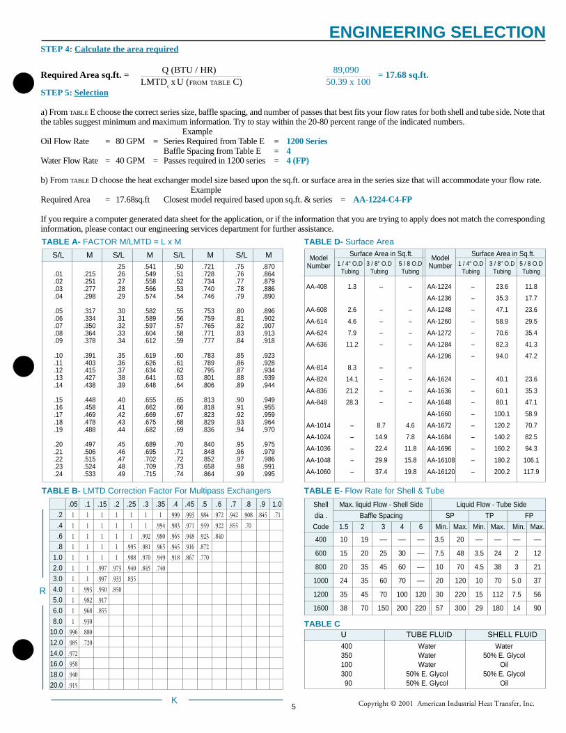
STEP 4: Calculate the area required
Required Area sq.ft. = Q (BTU / HR) 89,090 = 17.68 sq.ft.LMTD
c x
U (FROM TABLE C) 50.39 x 100
STEP 5: Selection
a) From TABLE E choose the correct series size, baffle spacing, and number of passes that best fits your flow rates for both shell and tube side. Note thatthe tables suggest minimum and maximum information. Try to stay within the 20-80 percent range of the indicated numbers.
ExampleOil Flow Rate = 80 GPM = Series Required from Table E =1200 Series
Baffle Spacing from Table E =4Water Flow Rate = 40 GPM = Passes required in 1200 series =4 (FP)
b) From TABLE D choose the heat exchanger model size based upon the sq.ft. or surface area in the series size that will accommodate your flow rate. Example
Required Area = 17.68sq.ft Closest model required based upon sq.ft. & series =AA-1224-C4-FP
If you require a computer generated data sheet for the application, or if the information that you are trying to apply does not match the correspondinginformation, please contact our engineering services department for further assistance.
ENGINEERING SELECTION
5
Copyright © 2001 American Industrial Heat Transfer, Inc.
GPM (Oil Through Cooler)
151258
1610
20
17
28
24
21
111914
22
25
23
26
27
34
31
30
3235
36
37
1
3
2
6
47
9
18
13
29
✙
✩
❍
✙
✩
✙
✩
✙
✩✙
✩✙
✙
✙
✙
✙
✙
✩
✩
✩✙✙
✙
✩✩
✩✙
✙
✙✙
❍
❍❍
❍✩
✩
✩✩
✩
✙ ✙
✙
✙ ✙❍
❍
❍
✩
✙✩ ✩
✩
❍
❍
❍❍
33
✙
✩
❍
✙
✩
✩
✙
✙
✩
✩
✩
✙
❍
✩
✩
✙
✙
❍
✙
300
200
1009080
70
60
50
40
30
20
10
15
987
6
5
4
3
23 4 5 6 7 8 9 10 15 20 40 60 80 100 200
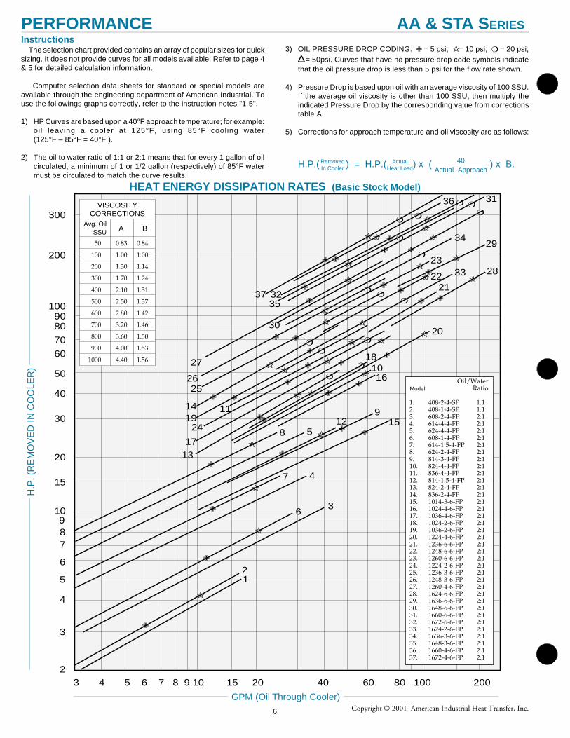
Oil/WaterRatio
1. 408-2-4-SP 1:12. 408-1-4-SP 1:13. 608-2-4-FP 2:14. 614-4-4-FP 2:15. 624-4-4-FP 2:16. 608-1-4-FP 2:17. 614-1.5-4-FP 2:18. 624-2-4-FP 2:19. 814-3-4-FP 2:110. 824-4-4-FP 2:111. 836-4-4-FP 2:112. 814-1.5-4-FP 2:113. 824-2-4-FP 2:114. 836-2-4-FP 2:115. 1014-3-6-FP 2:116. 1024-4-6-FP 2:117. 1036-4-6-FP 2:118. 1024-2-6-FP 2:119. 1036-2-6-FP 2:120. 1224-4-6-FP 2:121. 1236-6-6-FP 2:122. 1248-6-6-FP 2:123. 1260-6-6-FP 2:124. 1224-2-6-FP 2:125. 1236-3-6-FP 2:126. 1248-3-6-FP 2:127. 1260-4-6-FP 2:128. 1624-6-6-FP 2:129. 1636-6-6-FP 2:130. 1648-6-6-FP 2:131. 1660-6-6-FP 2:132. 1672-6-6-FP 2:133. 1624-2-6-FP 2:134. 1636-3-6-FP 2:135. 1648-3-6-FP 2:136. 1660-4-6-FP 2:137. 1672-4-6-FP 2:1
Model
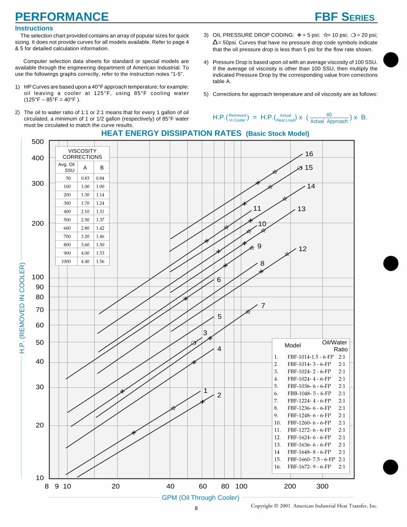
HEAT ENERGY DISSIPATION RATES (Basic Stock Model)
3) OIL PRESSURE DROP CODING: ✙ = 5 psi; ✩= 10 psi; ❍ = 20 psi;∆ = 50psi. Curves that have no pressure drop code symbols indicatethat the oil pressure drop is less than 5 psi for the flow rate shown.
4) Pressure Drop is based upon oil with an average viscosity of 100 SSU.If the average oil viscosity is other than 100 SSU, then multiply theindicated Pressure Drop by the corresponding value from correctionstable A.
5) Corrections for approach temperature and oil viscosity are as follows:
H.P.( ) = H.P.( ) x ( ) x B.RemovedIn Cooler
ActualHeat Load
The selection chart provided contains an array of popular sizes for quicksizing. It does not provide curves for all models available. Refer to page 4& 5 for detailed calculation information.
Computer selection data sheets for standard or special models areavailable through the engineering department of American Industrial. Touse the followings graphs correctly, refer to the instruction notes "1-5".
1) HP Curves are based upon a 40°F approach temperature; for example:oil leaving a cooler at 125°F, using 85°F cooling water(125°F – 85°F = 40°F ).
2) The oil to water ratio of 1:1 or 2:1 means that for every 1 gallon of oilcirculated, a minimum of 1 or 1/2 gallon (respectively) of 85°F watermust be circulated to match the curve results.
Instructions
40Actual Approach
H.P
. (R
EM
OV
ED
IN C
OO
LER
)
50 0.83 0.84
100 1.00 1.00
200 1.30 1.14
300 1.70 1.24
400 2.10 1.31
500 2.50 1.37
600 2.80 1.42
700 3.20 1.46
800 3.60 1.50
900 4.00 1.53
1000 4.40 1.56
Avg. OilSSU A B
VISCOSITYCORRECTIONS
PERFORMANCE AA & STA S ERIES
6
Copyright © 2001 American Industrial Heat Transfer, Inc.NOTES: We reserve the right to make reasonable design changes without notice.
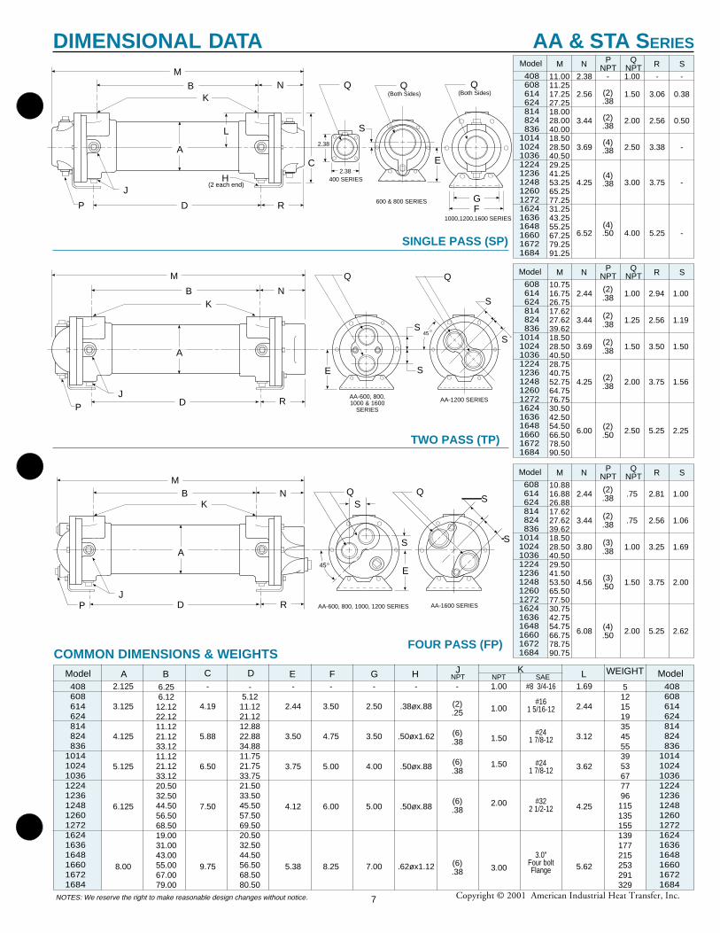
FOUR PASS (FP)
SINGLE PASS (SP)
TWO PASS (TP)
COMMON DIMENSIONS & WEIGHTSJ
NPT
6.256.12
12.1222.1211.1221.1233.1211.1221.1233.1220.5032.5044.5056.5068.5019.0031.0043.0055.0067.0079.00
2.125
3.125
4.125
5.125
6.125
8.00
-5.12
11.1221.1212.8822.8834.8811.7521.7533.7521.5033.5045.5057.5069.5020.5032.5044.5056.5068.5080.50
Model LF GEDCBA H408608614624814824836
10141024103612241236124812601272162416361648166016721684
-
4.19
5.88
6.50
7.50
9.75
-
2.44
3.50
3.75
4.12
5.38
-
3.50
4.75
5.00
6.00
8.25
-
2.50
3.50
4.00
5.00
7.00
-
.38øx.88
.50øx1.62
.50øx.88
.50øx.88
.62øx1.12
-
(2).25
(6).38
(6).38
(6).38
(6).38
1.69
2.44
3.12
3.62
4.25
5.62
51215193545553953677796
115135155139177215253291329
Model408608614624814824836
10141024103612241236124812601272162416361648166016721684
WEIGHTK
Model SRNM608614624814824836
10141024103612241236124812601272162416361648166016721684
10.7516.7526.7517.6227.6239.6218.5028.5040.5028.7540.7552.7564.7576.7530.5042.5054.5066.5078.5090.50
2.44
3.44
3.69
4.25
6.00
PNPT
QNPT
(2).38
(2).38
(2).38
(2).38
(2).50
1.00
1.25
1.50
2.00
2.50
2.94
2.56
3.50
3.75
5.25
1.00
1.19
1.50
1.56
2.25
Model SRNM608614624814824836
10141024103612241236124812601272162416361648166016721684
10.8816.8826.8817.6227.6239.6218.5028.5040.5029.5041.5053.5065.5077.5030.7542.7554.7566.7578.7590.75
2.44
3.44
3.80
4.56
6.08
PNPT
QNPT
(2).38
(2).38
(3).38
(3).50
(4).50
.75
.75
1.00
1.50
2.00
2.81
2.56
3.25
3.75
5.25
1.00
1.06
1.69
2.00
2.62
Model SRNM
408608614624814824836
10141024103612241236124812601272162416361648166016721684
11.0011.2517.2527.2518.0028.0040.0018.5028.5040.5029.2541.2553.2565.2577.2531.2543.2555.2567.2579.2591.25
2.38
2.56
3.44
3.69
4.25
6.52
PNPT
QNPT
-
(2).38
(2).38
(4).38
(4).38
(4).50
1.00
1.50
2.00
2.50
3.00
4.00
-
3.06
2.56
3.38
3.75
5.25
-
0.38
0.50
-
-
-
M
B
L
N
RD
J
C
QK
2.38
2.38400 SERIES
600 & 800 SERIES
(Both Sides)
F
H(2 each end)
Q(Both Sides)
Q
S
1000,1200,1600 SERIES
E
P
A
G
M
PR
N
AA-600, 800,1000 & 1600
SERIES
AA-1200 SERIES
Q
S
S
S
S
Q
45
A
BK
JD
E
AA-1600 SERIESAA-600, 800, 1000, 1200 SERIESR
MN
45
S
S
QS
S
Q
P
A
B
JD
K
E
SAE#8 3/4-16
#161 5/16-12
#241 7/8-12
#241 7/8-12
#322 1/2-12
3.0"Four boltFlange
NPT1.00
1.00
1.50
1.50
2.00
3.00
DIMENSIONAL DATA AA & STA S ERIES
7
Copyright © 2001 American Industrial Heat Transfer, Inc.
21
4
3
7
5
12
8
6
9
13
10
14
11
15
16
8 9 10 20 40 60 80 100 200 300
✙
✙
✩
✙
✙
✙
✙
✙
✙
✙
✙
✙
✙
✙
✩
✩✩
✩✩
✩
✩
✩
✩
❍
❍
✙
10
20
30
40
50
60
70
80
90
100
300
400
500
200
HEAT ENERGY DISSIPATION RATES (Basic Stock Model)
3) OIL PRESSURE DROP CODING: ✙ = 5 psi; ✩= 10 psi; ❍ = 20 psi;∆ = 50psi. Curves that have no pressure drop code symbols indicatethat the oil pressure drop is less than 5 psi for the flow rate shown.
4) Pressure Drop is based upon oil with an average viscosity of 100 SSU.If the average oil viscosity is other than 100 SSU, then multiply theindicated Pressure Drop by the corresponding value from correctionstable A.
5) Corrections for approach temperature and oil viscosity are as follows:
H.P.( ) = H.P.( ) x ( ) x B.RemovedIn Cooler
ActualHeat Load
The selection chart provided contains an array of popular sizes for quicksizing. It does not provide curves for all models available. Refer to page 4& 5 for detailed calculation information.
Computer selection data sheets for standard or special models areavailable through the engineering department of American Industrial. Touse the followings graphs correctly, refer to the instruction notes "1-5".
1) HP Curves are based upon a 40°F approach temperature; for example:oil leaving a cooler at 125°F, using 85°F cooling water(125°F – 85°F = 40°F ).
2) The oil to water ratio of 1:1 or 2:1 means that for every 1 gallon of oilcirculated, a minimum of 1 or 1/2 gallon (respectively) of 85°F watermust be circulated to match the curve results.
Instructions
40Actual Approach
Oil/Water Ratio
1. FBF-1014-1.5 - 6-FP 2:12. FBF-1014- 3 - 6-FP 2:13. FBF-1024- 2 - 6-FP 2:14. FBF-1024- 4 - 6-FP 2:15. FBF-1036- 6 - 6-FP 2:16. FBB-1048- 5 - 6-FP 2:17. FBF-1224- 4 - 6-FP 2:18. FBF-1236- 6 - 6-FP 2:19. FBF-1248- 6 - 6-FP 2:110. FBF-1260- 6 - 6-FP 2:111. FBF-1272- 6 - 6-FP 2:112. FBF-1624- 6 - 6-FP 2:113. FBF-1636- 6 - 6-FP 2:114 FBF-1648- 8 - 6-FP 2:115. FBF-1660- 7.5 - 6-FP 2:116. FBF-1672- 9 - 6-FP 2:1
Model
GPM (Oil Through Cooler)
H.P
. (R
EM
OV
ED
IN C
OO
LER
)
50 0.83 0.84
100 1.00 1.00
200 1.30 1.14
300 1.70 1.24
400 2.10 1.31
500 2.50 1.37
600 2.80 1.42
700 3.20 1.46
800 3.60 1.50
900 4.00 1.53
1000 4.40 1.56
Avg. OilSSU A B
VISCOSITYCORRECTIONS
PERFORMANCE FBF SERIES
8
Copyright © 2001 American Industrial Heat Transfer, Inc.
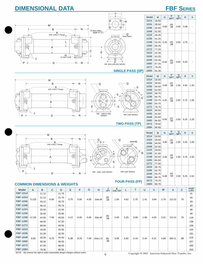
FOUR PASS (FP)
SINGLE PASS (SP)
TWO PASS (TP)
Model SRNM1014
1024
1036
1048
1224
1236
1248
1260
1272
1624
1636
1648
1660
1672
1684
18.50
28.50
40.50
52.50
28.75
40.75
52.75
64.75
76.75
30.50
42.50
54.50
66.50
78.50
90.50
3.69
4.25
6.00
PNPT
QNPT
(2).38
(2).38
(2).50
1.50
2.00
2.50
3.50
3.75
5.25
1.50
1.56
2.25
Model SRNM1014
1024
1036
1048
1224
1236
1248
1260
1272
1624
1636
1648
1660
1672
1684
18.50
28.50
40.50
52.50
29.50
41.50
53.50
65.50
77.50
30.75
42.75
54.75
66.75
78.75
90.75
3.80
4.56
6.08
PNPT
QNPT
(3).38
(3).50
(4).50
1.00
1.50
2.00
3.25
3.75
5.25
1.69
2.00
2.62
Model SRNM
1014
1024
1036
1048
1224
1236
1248
1260
1272
1624
1636
1648
1660
1672
1684
18.50
28.50
40.50
52.50
29.25
41.25
53.25
65.25
77.25
32.25
43.25
55.25
67.25
79.25
91.25
3.69
4.25
6.52
PNPT
QNPT
(4).38
(4).38
(4).50
2.00
3.00
4.00
3.38
3.75
5.25
-
-
-
NOTE: We reserve the right to make reasonable design changes without notice.
COMMON DIMENSIONS & WEIGHTSModel EC GBA F
FBF-1014
FBF-1024
FBF-1036
FBF-1048
FBF-1224
FBF-1236
FBF-1248
FBF-1260
FBF-1272
FBF-1624
FBF-1636
FBF-1648
FBF-1660
FBF-1672
FBF-1684
weight(LBS)
JNPTH TL U V W X ZD K
SAE FBF
11.12
21.12
33.12
45.12
20.50
32.50
44.50
56.50
68.50
19.00
31.00
43.00
55.00
67.00
79.00
5.125
6.125
8.00
11.75
21.75
33.75
45.75
21.50
33.50
45.50
57.50
69.50
20.50
32.50
44.50
56.50
68.50
80.50
6.50
7.50
9.75
3.75
4.12
5.38
5.00
6.00
8.25
4.00
5.00
7.00
.50øx.88
.50øx.88
.62øx1.12
(6).38
(6).38
(6).38
4.62
5.25
6.62
41
55
69
83
80
99
118
138
158
143
181
219
257
295
333
1.50
2.00
3.00
-
2.75
3.06
4.19
1.41
1.69
2.44
3.68
4.00
5.31
-
2.75
3.31
4.69
-
1/2-13
1/2-13
5/8-11
.75
.75
.88
M
B
L
A
N
RD
J
C
QK(Both Sides)
SAE 4-BOLT Flange
F
H(2 each end)
FBF 1000,1200,1600 SERIESP
G
TV
UW
X (four holes, depth of "Z")
E
FBF-1600 SERIESFBF - 1000, 1200 SERIESR
M
N
45
S
S
QS
S
Q
P
A
B
J
KSAE 4-BOLT Flange
D
E
M
P R
N
FBF - 1000 & 1600SERIES FBF-1200 SERIES
Q
S
S
S
SQ
45
A
B
J
KSAE 4-BOLT Flange
D
E
9
DIMENSIONAL DATA FBF S ERIES
Copyright © 2001 American Industrial Heat Transfer, Inc.
C
B
B
B
A
A
A
D
D
D
CC
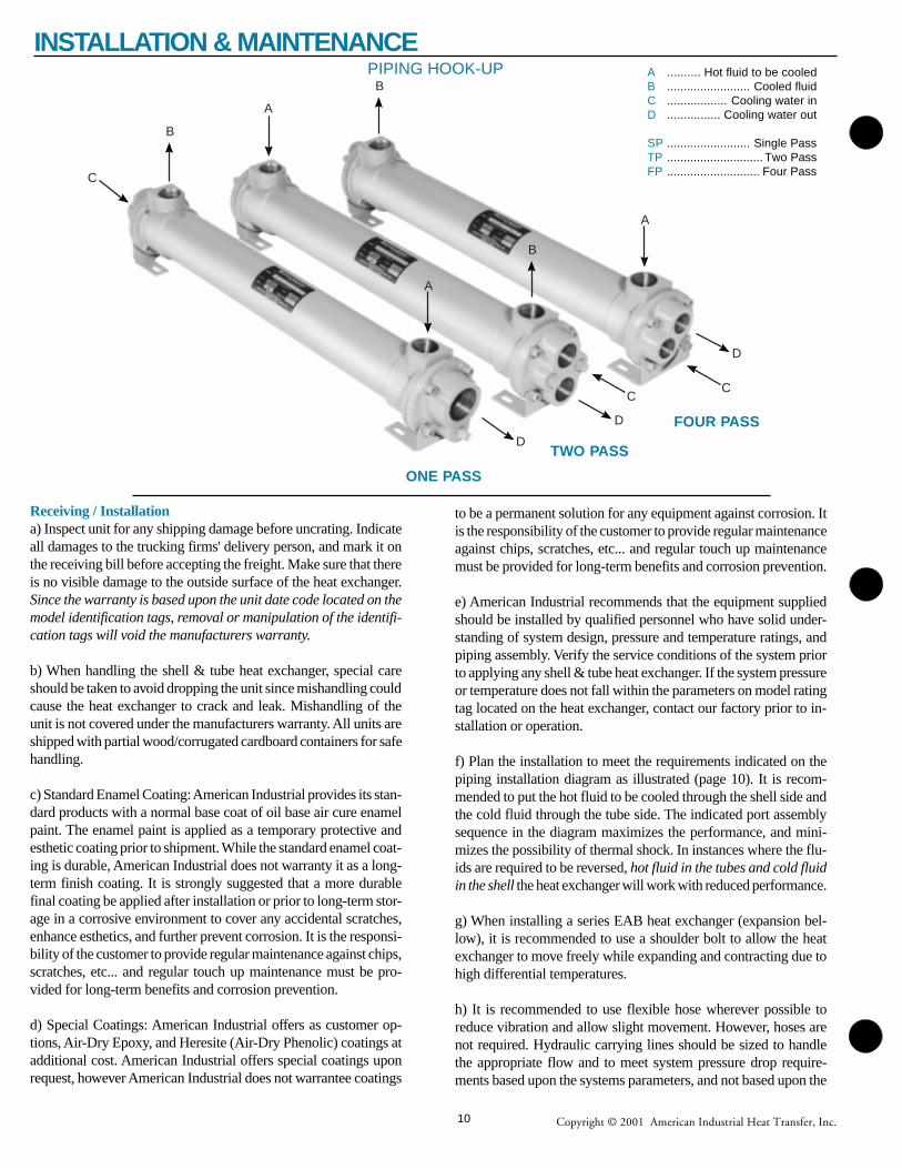
ONE PASS
TWO PASS
FOUR PASS
PIPING HOOK-UP A .......... Hot fluid to be cooledB ......................... Cooled fluidC .................. Cooling water inD ................ Cooling water out
SP ......................... Single PassTP ............................. Two PassFP ............................ Four Pass
Receiving / Installationa) Inspect unit for any shipping damage before uncrating. Indicateall damages to the trucking firms' delivery person, and mark it onthe receiving bill before accepting the freight. Make sure that thereis no visible damage to the outside surface of the heat exchanger.Since the warranty is based upon the unit date code located on themodel identification tags, removal or manipulation of the identifi-cation tags will void the manufacturers warranty.
b) When handling the shell & tube heat exchanger, special careshould be taken to avoid dropping the unit since mishandling couldcause the heat exchanger to crack and leak. Mishandling of theunit is not covered under the manufacturers warranty. All units areshipped with partial wood/corrugated cardboard containers for safehandling.
c) Standard Enamel Coating: American Industrial provides its stan-dard products with a normal base coat of oil base air cure enamelpaint. The enamel paint is applied as a temporary protective andesthetic coating prior to shipment. While the standard enamel coat-ing is durable, American Industrial does not warranty it as a long-term finish coating. It is strongly suggested that a more durablefinal coating be applied after installation or prior to long-term stor-age in a corrosive environment to cover any accidental scratches,enhance esthetics, and further prevent corrosion. It is the responsi-bility of the customer to provide regular maintenance against chips,scratches, etc... and regular touch up maintenance must be pro-vided for long-term benefits and corrosion prevention.
d) Special Coatings: American Industrial offers as customer op-tions, Air-Dry Epoxy, and Heresite (Air-Dry Phenolic) coatings atadditional cost. American Industrial offers special coatings uponrequest, however American Industrial does not warrantee coatings
to be a permanent solution for any equipment against corrosion. Itis the responsibility of the customer to provide regular maintenanceagainst chips, scratches, etc... and regular touch up maintenancemust be provided for long-term benefits and corrosion prevention.
e) American Industrial recommends that the equipment suppliedshould be installed by qualified personnel who have solid under-standing of system design, pressure and temperature ratings, andpiping assembly. Verify the service conditions of the system priorto applying any shell & tube heat exchanger. If the system pressureor temperature does not fall within the parameters on model ratingtag located on the heat exchanger, contact our factory prior to in-stallation or operation.
f) Plan the installation to meet the requirements indicated on thepiping installation diagram as illustrated (page 10). It is recom-mended to put the hot fluid to be cooled through the shell side andthe cold fluid through the tube side. The indicated port assemblysequence in the diagram maximizes the performance, and mini-mizes the possibility of thermal shock. In instances where the flu-ids are required to be reversed, hot fluid in the tubes and cold fluidin the shell the heat exchanger will work with reduced performance.
g) When installing a series EAB heat exchanger (expansion bel-low), it is recommended to use a shoulder bolt to allow the heatexchanger to move freely while expanding and contracting due tohigh differential temperatures.
h) It is recommended to use flexible hose wherever possible toreduce vibration and allow slight movement. However, hoses arenot required. Hydraulic carrying lines should be sized to handlethe appropriate flow and to meet system pressure drop require-ments based upon the systems parameters, and not based upon the
INSTALLATION & MAINTENANCE
10
Copyright © 2001 American Industrial Heat Transfer, Inc.
units supply and return connection size. We recommend that a lowcracking pressure direct acting relief valve be installed at the heatexchanger inlet to protect it from pressure spikes by bypassing oilin the event the system experiences a high flow surge. If preventa-tive filtration is used it should be located ahead of the cooler onboth shell and tube side to catch any scale or sludge from the sys-tem before it enters the cooler. Failure to install filters ahead of theheat exchanger could lead to possible heat exchanger failure due tohigh pressure if the system filters plug.
i) Standard shell & tube coolers are built with a rolled tube-sheetconstruction. However, the differential operating temperature be-tween the entering shell side fluid and the entering tube side fluidshould not exceed 150°F. If this condition exists, a severe thermalshock could occur leading to product failure and mixing of thefluids. For applications with a differential temperatures of 150°For more, we recommend using a series with a floating tube-sheet,u-tube, or expansion joint to reduce the potential for the effects ofthermal shock.
j) Water requirements vary from location to location. If the sourceof cooling water is from other than a municipal water supply, it isrecommended that a water strainer be installed ahead of the heatexchanger to prevent dirt and debris from entering and cloggingthe flow passages. If a water modulating valve is used it is recom-mended to be installed at the inlet to the cooler to regulate thewater flow.
k) For steam service, or other related applications, please consultour engineering department for additional information.
Maintenancea) Inspect the heat exchanger for loosened bolts, connections, rustspots, corrosion, and for internal or external fluid leakage. Anycorroded surfaces should be cleaned and recoated with paint.
b) Shell side: In many cases with clean hydraulic system oils it willnot be necessary to flush the interior of the shell side of the cooler.In circumstances where the quality of hydraulic fluid is in ques-tion, the shell side should be disconnected and flushed on a yearlybasis with a clean flushing oil/solvent to remove any sludge thathas been deposited. For severe cases where the unit is plugged andcannot be flushed clean with solvent, the heat exchanger should bereplaced to maintain the proper cooling performance.
c) Tube side: In many cases it will be necessary to clean the tubeside of the heat exchanger due to poor fluid quality, debris, cal-cium deposits, corrosion, mud, sludge, seaweed, etc.... To cleanthe tube side, flush with clean water or any good quality commer-cial cleaner that does not attack the particular material of construc-tion. With straight tube heat exchangers you can use a rod to care-fully push any debris out of the tubes.
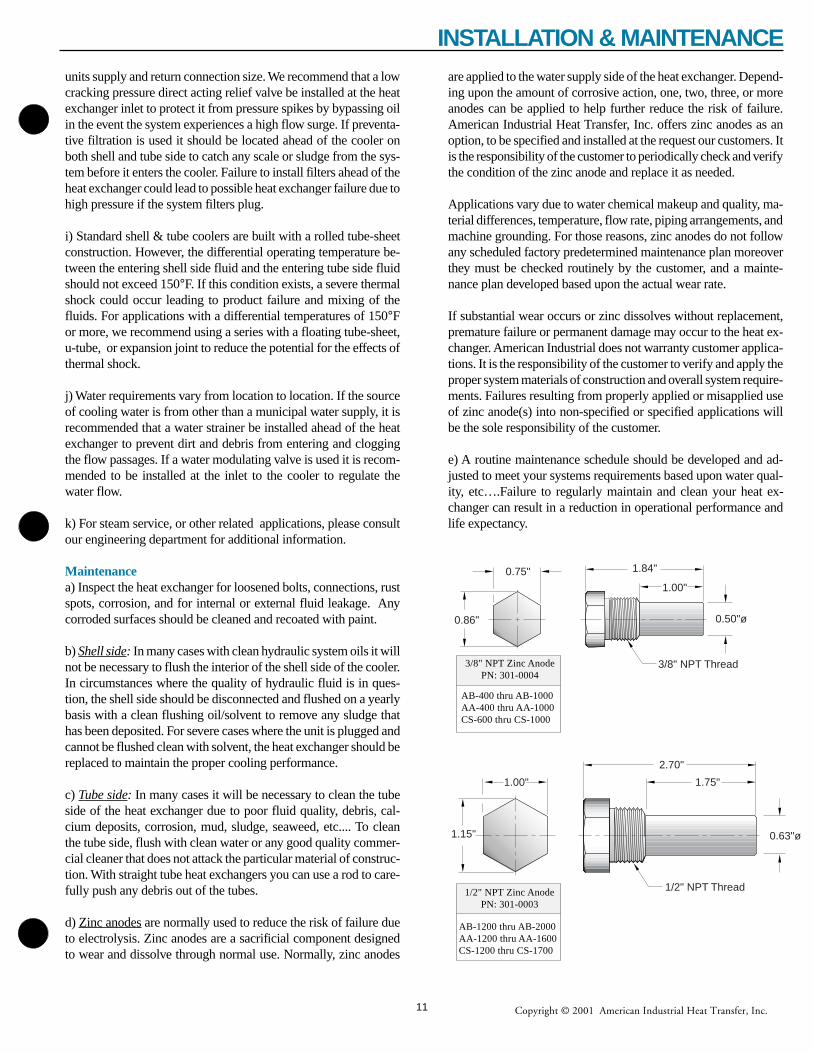
d) Zinc anodes are normally used to reduce the risk of failure dueto electrolysis. Zinc anodes are a sacrificial component designedto wear and dissolve through normal use. Normally, zinc anodes
are applied to the water supply side of the heat exchanger. Depend-ing upon the amount of corrosive action, one, two, three, or moreanodes can be applied to help further reduce the risk of failure.American Industrial Heat Transfer, Inc. offers zinc anodes as anoption, to be specified and installed at the request our customers. Itis the responsibility of the customer to periodically check and verifythe condition of the zinc anode and replace it as needed.
Applications vary due to water chemical makeup and quality, ma-terial differences, temperature, flow rate, piping arrangements, andmachine grounding. For those reasons, zinc anodes do not followany scheduled factory predetermined maintenance plan moreoverthey must be checked routinely by the customer, and a mainte-nance plan developed based upon the actual wear rate.
If substantial wear occurs or zinc dissolves without replacement,premature failure or permanent damage may occur to the heat ex-changer. American Industrial does not warranty customer applica-tions. It is the responsibility of the customer to verify and apply theproper system materials of construction and overall system require-ments. Failures resulting from properly applied or misapplied useof zinc anode(s) into non-specified or specified applications willbe the sole responsibility of the customer.
e) A routine maintenance schedule should be developed and ad-justed to meet your systems requirements based upon water qual-ity, etc….Failure to regularly maintain and clean your heat ex-changer can result in a reduction in operational performance andlife expectancy.
3/8" NPT Thread
1.84"
1.00"
0.86" 0.50"ø
0.75"
1/2" NPT Thread
2.70"
1.15" 0.63"ø
1.00" 1.75"
3/8" NPT Zinc AnodePN: 301-0004
AB-400 thru AB-1000AA-400 thru AA-1000CS-600 thru CS-1000
1/2" NPT Zinc AnodePN: 301-0003
AB-1200 thru AB-2000AA-1200 thru AA-1600CS-1200 thru CS-1700
11
INSTALLATION & MAINTENANCE
Copyright © 2001 American Industrial Heat Transfer, Inc.
APPLICATIONS & SPECS. ("Y" Strainers)These strainers are engineered for water or steam, and are adaptable for many other uses. Cleaning is accomplished by simply removing a pipeplug without disconnecting any piping. Or, if it is desirable to clean without interrupting service, a blow-off valve can be connected to theclean-out opening. Note: Pumps, control valves, traps, or other equipment controlling the flow of liquids or gases require proper protectionwith strainers for trouble free operation.
18 - Y BRASS STRAINERSThe 18 - Y strainer body is a sturdy red brass casting. Standard units have 50 mesh brass wire screens. Brazing connections are available onspecial order instead of pipe threads.
20 - Y STRAINERSThe 20 - Y strainer has a heavy cast iron body with accurately machined pipe thread inlet and outlet (National Pipe Thread N.P.T.). It containsa strainer screen of 0.02" thick brass with 100, 1/16" perforations per inch.
�������������������������������������������������
C
D
APipe Thread
INLET
OUTLET
EClean-outOpening
Pipe Thread
B
MODELSIZE
A(NPT)
DIMENSIONS (Inches) WT.(lbs.)B C D
E(NPT)
18 - Y
0.38"0.50"0.75"1.00"
2.50"2.50"3.50"3.50"
2.63"2.63"3.75"3.75"
2.00"2.00"2.75"2.75"
0.25"0.25"0.50"0.50"
0.750.751.751.75
20 - Y
0.50"0.75"1.00"1.25"1.50"2.00"
4.00"4.00"4.75"6.00"6.00"8.13"
3.25"3.25"4.38"5.13"5.13"6.38"
2.50"2.50"3.38"3.88"3.88"4.63"
0.38"0.38"0.75"0.75"0.75"0.75"
1.751.754.004.754.75
13.00
PRESSURE RATINGS, ALL MODELS: 125lbs. per Sq.In.
"Y" STRAINER (for Shell & Tube Heat Exchangers And Air/Oil Coolers)
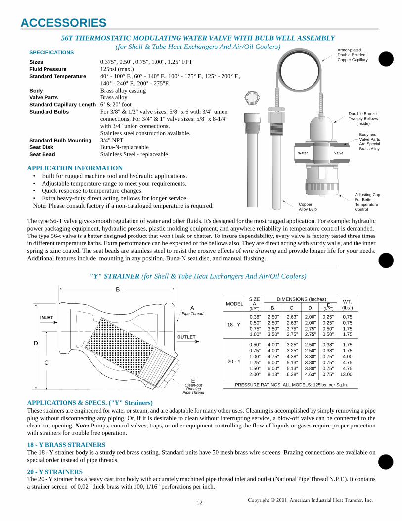
56T THERMOSTATIC MODULATING WATER VALVE WITH BULB WELL ASSEMBLY(for Shell & Tube Heat Exchangers And Air/Oil Coolers)
SPECIFICATIONS
Sizes 0.375", 0.50", 0.75", 1.00", 1.25" FPTFluid Pressure 125psi (max.)Standard Temperature 40° - 100° F., 60° - 140° F., 100° - 175° F., 125° - 200° F.,
140° - 240° F., 200° - 275°F.Body Brass alloy castingValve Parts Brass alloyStandard Capillary Length 6’ & 20’ footStandard Bulbs For 3/8" & 1/2" valve sizes: 5/8" x 6 with 3/4" union
connections. For 3/4" & 1" valve sizes: 5/8" x 8-1/4"with 3/4" union connections.Stainless steel construction available.
Standard Bulb Mounting 3/4" NPTSeat Disk Buna-N-replaceableSeat Bead Stainless Steel - replaceable Water Valve
Durable BronzeTwo-ply Bellows (inside)
Armor-platedDouble BraidedCopper Capillary
Body andValve PartsAre Special Brass Alloy
Adjusting Cap For BetterTemperatureControl
CopperAlloy Bulb
APPLICATION INFORMATION• Built for rugged machine tool and hydraulic applications.• Adjustable temperature range to meet your requirements.• Quick response to temperature changes.• Extra heavy-duty direct acting bellows for longer service.Note: Please consult factory if a non-cataloged temperature is required.
The type 56-T valve gives smooth regulation of water and other fluids. It's designed for the most rugged application. For example: hydraulicpower packaging equipment, hydraulic presses, plastic molding equipment, and anywhere reliability in temperature control is demanded.The type 56-t valve is a better designed product that won't leak or chatter. To insure dependability, every valve is factory tested three timesin different temperature baths. Extra performance can be expected of the bellows also. They are direct acting with sturdy walls, and the innerspring is zinc coated. The seat beads are stainless steel to resist the erosive effects of wire drawing and provide longer life for your needs.Additional features include mounting in any position, Buna-N seat disc, and manual flushing.
ACCESSORIES
12

Copyright © 2001 American Industrial Heat Transfer, Inc.
Since 1985, American Industrial Heat Transfer, Inc. is pleased to offer more than thirty fully manufactured product lines tomeet the requirements of most heat transfer needs. American Industrial manufactures all of the heat exchangers as advertised, so thatyour company is never compromised. Modern state-of-the-art CNC manufacturing machinery, top quality raw materials, andprofessional engineering services are all offered by American Industrial for the convenience of our customers.
Many innovative liquid and air-cooled heat exchanger designs are offered for a wide variety of mobile and industrial applica-tions. The latest technology data processing, manufacturing, and engineering systems are employed throughout our company.
American Industrial is proud to offer one of the strongest authorized distribution networks in the industry with worldwidecoverage. Direct access to professional engineering services, no service charge 24 hour expedite delivery, custom modifications,competitive pricing, etc... are just a few benefits of being an American Industrial customer.
We know that our future relies on the future of our customers. For that reason we have invested in high-technology automationand professional personnel to give us the competitive edge far into the future.
If you would like to know more about our products, please contact your local American Industrial distributor or contact ourcompany. You can see us on the web at www.aihti.com. We appreciate your business and we hope to share with you in yoursuccesses.
A full line of engineering services are available to assist withtechnical support, design, Cad drawings, etc…
Our courteous and professional staff is available to providequality customer service assistance.
MISSION STATEMENT
To manufacture Heat Transfer products by applying state-of-the-art technologies, with the ability to serve a widevariety of industries through professional distribution affiliations throughout North America and abroad.
American Industrial's state-of-the-art manufacturing facility.
13
COMPANY PROFILE
Copyright © 2001 American Industrial Heat Transfer, Inc.
MANUFACTURING
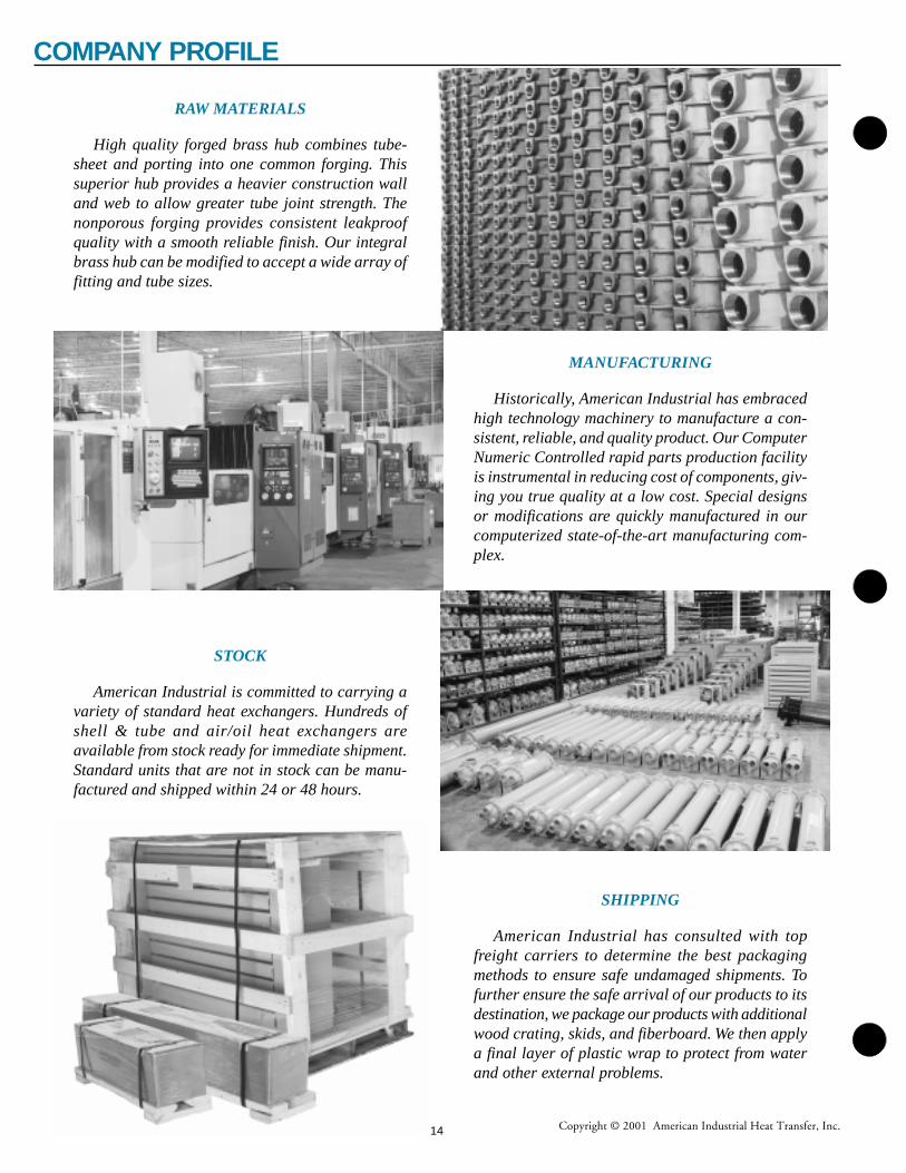
Historically, American Industrial has embracedhigh technology machinery to manufacture a con-sistent, reliable, and quality product. Our ComputerNumeric Controlled rapid parts production facilityis instrumental in reducing cost of components, giv-ing you true quality at a low cost. Special designsor modifications are quickly manufactured in ourcomputerized state-of-the-art manufacturing com-plex.
STOCK
American Industrial is committed to carrying avariety of standard heat exchangers. Hundreds ofshell & tube and air/oil heat exchangers areavailable from stock ready for immediate shipment.Standard units that are not in stock can be manu-factured and shipped within 24 or 48 hours.
SHIPPING
American Industrial has consulted with topfreight carriers to determine the best packagingmethods to ensure safe undamaged shipments. Tofurther ensure the safe arrival of our products to itsdestination, we package our products with additionalwood crating, skids, and fiberboard. We then applya final layer of plastic wrap to protect from waterand other external problems.
RAW MATERIALS
High quality forged brass hub combines tube-sheet and porting into one common forging. Thissuperior hub provides a heavier construction walland web to allow greater tube joint strength. Thenonporous forging provides consistent leakproofquality with a smooth reliable finish. Our integralbrass hub can be modified to accept a wide array offitting and tube sizes.
14
COMPANY PROFILE
Copyright © 2001 American Industrial Heat Transfer, Inc.
Limited WarrantySeller makes no warranties expressed or implied,
including but not by way of limitation, any implied warrantyof merchantability and any implied warranty of fitness for aparticular purpose, on any order except that seller warrantstitle to all goods furnished by seller and except that sellerwarrants for a period of one year from the date mark locatedon the seller's identification tag that all goods described onseller's acknowledgment of purchaser's purchase order will bemanufactured in accordance with the specifications, if any, setforth in said purchase order and expressly accepted in seller'sacknowledgment subject to seller's standard manufacturingvariations and practices. In the case of components oraccessories furnished by suppliers to seller, purchaser'swarranty from seller shall be limited to the warranty of thecomponent or accessory supplier. The foregoing warrantiesare the sole and exclusive warranties applicable to the goodsdelivered under this order, and all other warranties, express orimplied, including without limitation any warranty of mer-chantability, are hereby expressly disclaimed and negated.Without limiting the generality of the foregoing, purchaseracknowledges that seller's products are not packaged orprotected for long periods of storage and thus may corrode orrust over time.
Limitation of Purchaser's Remedies; Exclusive of Dam-ages
Purchaser's remedies with respect to any claimarising out of any order, any goods delivered pursuant to anyorder and expressly accepted in seller's acknowledgment, orseller's performance in connection with any order, including,without limitation, any claim arising out of any recall, defector alleged defect in any goods or services furnished by seller,shall be limited exclusively to the right of repair or replace-ment of such goods or services, at seller's option. Without inany way limiting the generality of the foregoing, in no eventshall seller be liable for any consequential or incidentaldamages, including, without limitation, any loss of antici-pated profits incurred by purchaser with respect to any goodsor services furnished by seller, or any damages arising frominjuries to persons as a result of purchaser's or a third party'snegligence. Seller's warranty does not cover failures resultingfrom the improper installation, mounting design or applica-tion or from corrosion. The provisions of this paragraph are amaterial term of this transaction.
DisputesSeller and purchaser agree to submit any disputes
regarding any order, any goods delivered pursuant to anyorder and expressly accepted in seller's acknowledgment, orseller's performance in connection with any order, includingwithout limitation seller's limited warranty obligation, tomediation by an independent mediator to be mutually agreedupon by seller and purchaser. The cost of such mediationshall be borne equally by seller and purchaser. In the eventsuch mediation does not resolve their dispute, seller andpurchaser agree to submit such dispute to an independentarbitrator, to be mutually agreed upon by seller and purchaseror, otherwise, chosen by the mediator. Seller and purchaseragree that all mediation and arbitration shall be conducted inZion, Illinois. The non-prevailing party at the arbitration
shall pay the prevailing party's attorneys' fees and costsincurred in participating in the arbitration.
Governing LawSeller and Purchaser's agreement shall be governed
by and interpreted in accordance with the laws of the State ofIllinois of the United States of America. Manufacture,shipment and delivery are subject to any prohibition, restric-tion, priority, allocation, regulation or condition imposed byor on behalf of the United States of America or any othergovernmental body with appropriate jurisdiction which mayprevent or interfere with fulfillment of any order.
Permissible VariationsGoods shipped by Seller shall be within the limits
and sizes published by Seller, subject, however, to Seller'sright to ship overages or underages in accordance withSeller's standard practices and goods shipped by Seller will besubject to standard variations provided such variations arenon-functional or are not material in nature.
Technical Assistance and AdviceSeller's warranty shall not be enlarged and no
obligation or liability shall arise out of Seller's rendering oftechnical assistance, technical advice facilities, service orrecommendations made by Seller in connection withPurchaser's purchases of the goods hereunder. Said technicalservices, advice, assistance or recommendations made bySeller or any representative of Seller concerning any use orapplication of any goods furnished hereunder is believed to bereliable, but SELLER MAKES NO WARRANTY, EXPRESSOR IMPLIED, AND THE SAME ARE HEREBY EX-PRESSLY DISCLAIMED as to the same and the results to beobtained. Purchaser assumes all responsibility for loss ordamage resulting from the use of any such goods.
For standard dimensional information please refer toour corresponding product brochure. For informationregarding a special engineered product please contact ourcompany. All specially engineered products specifying a 5-digit suffix will be supplied with a drawing for customerapproval at the time of purchase. Additional costs may beadded if requirements should change from the originalspecifications, or have been initially overlooked. Please beaware that "normal shipping" lead-times are estimated basedupon components in stock at the time of quotation, extendedshipping time up to as much as two weeks or more may berequired if changes to inventory availability occur. Cancella-tion charges will be incurred for special order equipment.
American Industrial Heat Transfer, Inc. provides acomplete installation manual included with each unit soldcontaining a complete copy of our 3 page"Terms and Condi-tions of Sale". If an installation manual was not received ormisplaced for your equipment additional copies may beacquired. To receive a copy of American Industrial HeatTransfer, Inc. Installation Manual including "Standard Termsand Conditions of Sale" please refer to the following sources.1) The American Industrial product catalog. 2) Our Internetsite www.aihti.com, 3) Contact American Industrial directlyat 1-847-731-1000.
PARTIAL TERMS & CONDITIONS
15
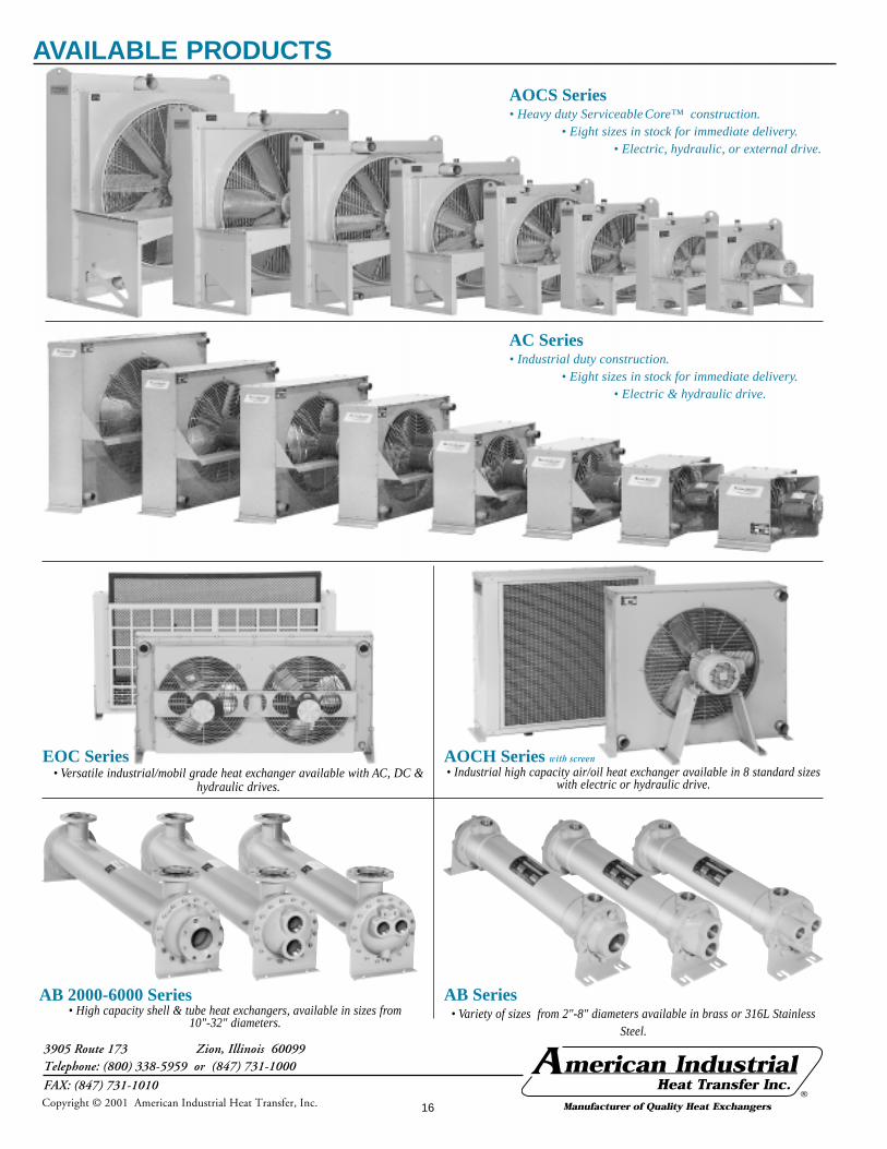
AB 2000-6000 Series• High capacity shell & tube heat exchangers, available in sizes from
10"-32" diameters.
AOCS Series• Heavy duty Serviceable Core™ construction.
• Eight sizes in stock for immediate delivery.• Electric, hydraulic, or external drive.
EOC Series• Versatile industrial/mobil grade heat exchanger available with AC, DC &
hydraulic drives.
AC Series• Industrial duty construction.
• Eight sizes in stock for immediate delivery.• Electric & hydraulic drive.
AB Series• Variety of sizes from 2"-8" diameters available in brass or 316L Stainless
Steel.
AOCH Series with screen
• Industrial high capacity air/oil heat exchanger available in 8 standard sizeswith electric or hydraulic drive.
3905 Route 173 Zion, Illinois 60099Telephone: (800) 338-5959 or (847) 731-1000
FAX: (847) 731-1010®
AVAILABLE PRODUCTS
Copyright © 2001 American Industrial Heat Transfer, Inc. 16