Embed Size (px)
Citation preview

User Training Workbook
HeartStart MRx M3535A/M3536A

Notice
About This EditionPublication number 453564045051
Edition 6
Printed in the USA
To determine the product level version to which this guide applies to, refer to the version level on the label of the User Documentation CD-ROM that accompanied the device. This information is subject to change without notice.
Philips shall not be liable for errors contained herein or for incidental or consequential damages in connection with the furnishing, performance, or use of this material.
Edition History
Copyright
Copyright © 2013
Koninklijke Philips N.V.
All rights are reserved. Permission is granted to copy and distribute this document for your organization’s internal educational use. Reproduction and/or distribution outside your organization in whole or in part is prohibited without the prior written consent of the copyright holder.
SMART Biphasic is a registered trademark of Philips.
Microstream® and FilterLine® are registered trademarks of Oridion Medical Ltd. Smart CapnoLine™ is a trademark of Oridion Medical Ltd.Q-CPR® is a registered trademark of Laerdal Medical.The HeartStart MRx contains an Ezurio PC Card with Bluetooth® wireless technology. The Bluetooth wordmark and logos are owned by the Bluetooth SIG, Inc. and any use of such marks by Ezurio is under license.
Other trademarks and trade names are those of their respective owners.
Use of supplies or accessories other than those recommended by Philips may compromise product performance.
THIS PRODUCT IS NOT INTENDED FOR HOME USE.
IN THE U.S., FEDERAL LAW RESTRICTS THIS DEVICE TO SALE ON OR BY THE ORDER OF A PHYSICIAN.
Medical Device Directive
The HeartStart MRx complies with the requirements of the Medical Device Directive 93/42/EEC and carries the
0123 mark accordingly.
Manufacturer:
Philips Healthcare3000 Minuteman RoadAndover, MA 01810
Authorized EU-representative:
Philips Medizin Systeme Böblingen GmbHHewlett Packard Str. 271034 BöblingenGermany
Canada EMC:ICES-001
U.S. FCC and Industry Canada Radio Compliance:
Contains FCC ID: PQC-WMTS-MODULE
When using the IntelliVue networking option, operation of this equipment requires the prior coordination with a frequency coordinator designated by the FCC for the Wireless Medical Telemetry Service. This device complies with Part 15 of the FCC rules and RSS-210 of Industry Canada. Operation is subject to the following conditions:
• This device may not cause harmful interference.
• This device must accept any interference received, including interference that may cause undesired operation.
Any changes or modifications to this equipment not expressly approved by Philips Medical Systems may cause harmful radio frequency interference and void your authority to operate this equipment.
Edition Print Date
1 September, 2006
2 February, 2007
3 August, 2007
4 May, 2009
5 December, 2011
6 August 2013
i

China:
After Sales Service: Beijing MEHECO-PHILIPS Medical Equipment Service Center.After Sales Service Address: No. 208, 2nd District, Wang Jing Li Ze Zhong Yuan, Chao Yang District, Beijing.Postal code: 100102.Telephone: 010-64392415.Registration number: SFDA(I)20043211207.Product Standard number: YZB/USA 52-21.
For the Declaration of Conformity Statement, please see the Philips Medical web site at http://incenter.medical.philips.com/PMSPublic. Scroll over the Quality and Regulatory Tab located in the upper left corner of the window. Click to select Regulatory by Modality. Then click to select Defibrillators and select the entry for Declaration of Conformity (DoC).
Warning
Radio frequency (RF) interference from nearby transmitting devices may degrade the performance of the HeartStart MRx. Electromagnetic compatibility with surrounding devices should be assessed prior to using the monitor/defibrillator.
ii

This workbook should be used primarily for HeartStart MRx instructor-based end-user training, along with the 453564045041 Instructor Guide. The workbook contains the following conventions:
"Voice" represents voice prompt messages
Text represents messages that appear on the HeartStart MRx display
Text represents options that appear on HeartStart MRx menus
[Soft key] represents soft key labels that appear on the display above thebutton to which they correspond
iii

iv
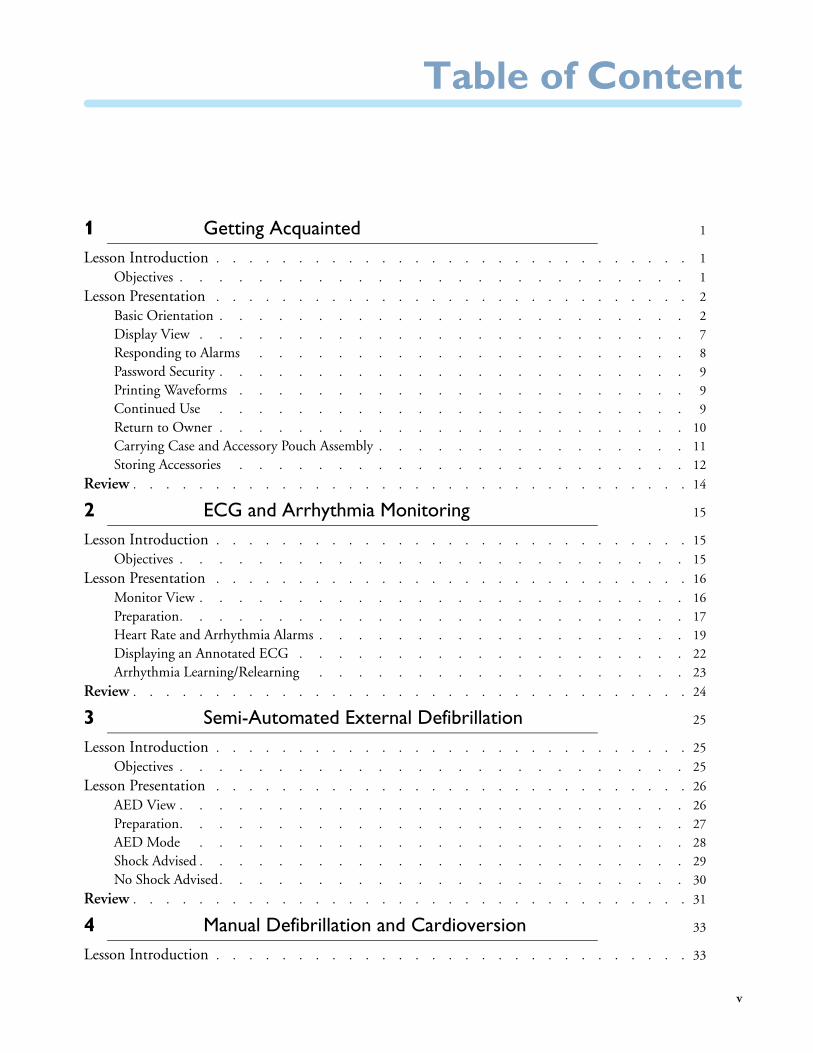
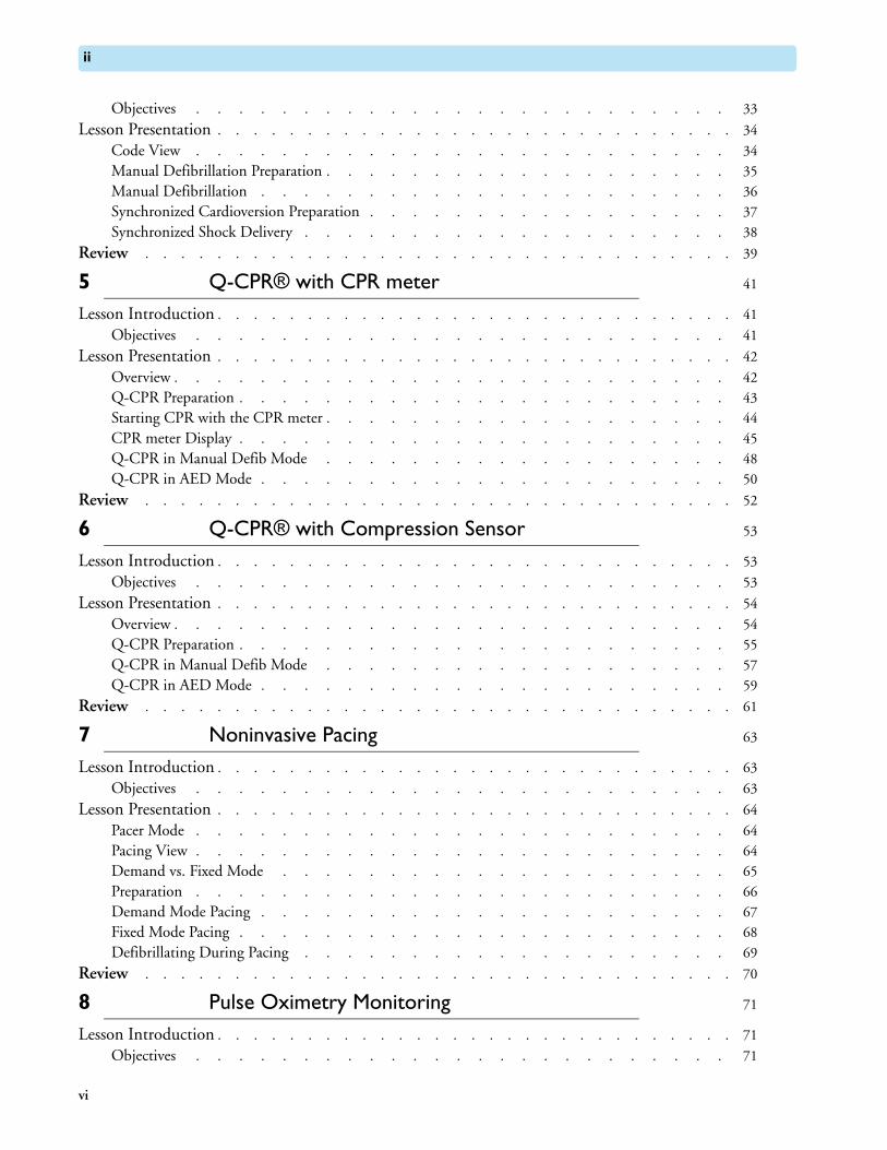
Table of Content
1 Getting Acquainted 1
Lesson Introduction . . . . . . . . . . . . . . . . . . . . . . . . . . . . . 1
Objectives . . . . . . . . . . . . . . . . . . . . . . . . . . 1
Lesson Presentation . . . . . . . . . . . . . . . . . . . . . . . . . . . . . 2
Basic Orientation . . . . . . . . . . . . . . . . . . . . . . . . 2
Display View . . . . . . . . . . . . . . . . . . . . . . . . . 7
Responding to Alarms . . . . . . . . . . . . . . . . . . . . . . 8
Password Security . . . . . . . . . . . . . . . . . . . . . . . . 9
Printing Waveforms . . . . . . . . . . . . . . . . . . . . . . . 9
Continued Use . . . . . . . . . . . . . . . . . . . . . . . . 9
Return to Owner . . . . . . . . . . . . . . . . . . . . . . . . 10
Carrying Case and Accessory Pouch Assembly . . . . . . . . . . . . . . . . 11
Storing Accessories . . . . . . . . . . . . . . . . . . . . . . . 12
Review . . . . . . . . . . . . . . . . . . . . . . . . . . . . . . . . . . 14
2 ECG and Arrhythmia Monitoring 15
Lesson Introduction . . . . . . . . . . . . . . . . . . . . . . . . . . . . . 15
Objectives . . . . . . . . . . . . . . . . . . . . . . . . . . 15
Lesson Presentation . . . . . . . . . . . . . . . . . . . . . . . . . . . . . 16
Monitor View . . . . . . . . . . . . . . . . . . . . . . . . . 16
Preparation. . . . . . . . . . . . . . . . . . . . . . . . . . 17
Heart Rate and Arrhythmia Alarms . . . . . . . . . . . . . . . . . . . 19
Displaying an Annotated ECG . . . . . . . . . . . . . . . . . . . . 22
Arrhythmia Learning/Relearning . . . . . . . . . . . . . . . . . . . 23
Review . . . . . . . . . . . . . . . . . . . . . . . . . . . . . . . . . . 24
3 Semi-Automated External Defibrillation 25
Lesson Introduction . . . . . . . . . . . . . . . . . . . . . . . . . . . . . 25
Objectives . . . . . . . . . . . . . . . . . . . . . . . . . . 25
Lesson Presentation . . . . . . . . . . . . . . . . . . . . . . . . . . . . . 26
AED View . . . . . . . . . . . . . . . . . . . . . . . . . . 26
Preparation. . . . . . . . . . . . . . . . . . . . . . . . . . 27
AED Mode . . . . . . . . . . . . . . . . . . . . . . . . . 28
Shock Advised . . . . . . . . . . . . . . . . . . . . . . . . . 29
No Shock Advised. . . . . . . . . . . . . . . . . . . . . . . . 30
Review . . . . . . . . . . . . . . . . . . . . . . . . . . . . . . . . . . 31
4 Manual Defibrillation and Cardioversion 33
Lesson Introduction . . . . . . . . . . . . . . . . . . . . . . . . . . . . . 33
v
ii
Objectives . . . . . . . . . . . . . . . . . . . . . . . . . 33
Lesson Presentation . . . . . . . . . . . . . . . . . . . . . . . . . . . . . 34
Code View . . . . . . . . . . . . . . . . . . . . . . . . . 34
Manual Defibrillation Preparation . . . . . . . . . . . . . . . . . . . 35
Manual Defibrillation . . . . . . . . . . . . . . . . . . . . . . 36
Synchronized Cardioversion Preparation . . . . . . . . . . . . . . . . . 37
Synchronized Shock Delivery . . . . . . . . . . . . . . . . . . . . 38
Review . . . . . . . . . . . . . . . . . . . . . . . . . . . . . . . . . 39
5 Q-CPR® with CPR meter 41
Lesson Introduction . . . . . . . . . . . . . . . . . . . . . . . . . . . . . 41
Objectives . . . . . . . . . . . . . . . . . . . . . . . . . 41
Lesson Presentation . . . . . . . . . . . . . . . . . . . . . . . . . . . . . 42
Overview . . . . . . . . . . . . . . . . . . . . . . . . . . 42
Q-CPR Preparation . . . . . . . . . . . . . . . . . . . . . . . 43
Starting CPR with the CPR meter . . . . . . . . . . . . . . . . . . . 44
CPR meter Display . . . . . . . . . . . . . . . . . . . . . . . 45
Q-CPR in Manual Defib Mode . . . . . . . . . . . . . . . . . . . 48
Q-CPR in AED Mode . . . . . . . . . . . . . . . . . . . . . . 50
Review . . . . . . . . . . . . . . . . . . . . . . . . . . . . . . . . . 52
6 Q-CPR® with Compression Sensor 53
Lesson Introduction . . . . . . . . . . . . . . . . . . . . . . . . . . . . . 53
Objectives . . . . . . . . . . . . . . . . . . . . . . . . . 53
Lesson Presentation . . . . . . . . . . . . . . . . . . . . . . . . . . . . . 54
Overview . . . . . . . . . . . . . . . . . . . . . . . . . . 54
Q-CPR Preparation . . . . . . . . . . . . . . . . . . . . . . . 55
Q-CPR in Manual Defib Mode . . . . . . . . . . . . . . . . . . . 57
Q-CPR in AED Mode . . . . . . . . . . . . . . . . . . . . . . 59
Review . . . . . . . . . . . . . . . . . . . . . . . . . . . . . . . . . 61
7 Noninvasive Pacing 63
Lesson Introduction . . . . . . . . . . . . . . . . . . . . . . . . . . . . . 63
Objectives . . . . . . . . . . . . . . . . . . . . . . . . . 63
Lesson Presentation . . . . . . . . . . . . . . . . . . . . . . . . . . . . . 64
Pacer Mode . . . . . . . . . . . . . . . . . . . . . . . . . 64
Pacing View . . . . . . . . . . . . . . . . . . . . . . . . . 64
Demand vs. Fixed Mode . . . . . . . . . . . . . . . . . . . . . 65
Preparation . . . . . . . . . . . . . . . . . . . . . . . . . 66
Demand Mode Pacing . . . . . . . . . . . . . . . . . . . . . . 67
Fixed Mode Pacing . . . . . . . . . . . . . . . . . . . . . . . 68
Defibrillating During Pacing . . . . . . . . . . . . . . . . . . . . 69
Review . . . . . . . . . . . . . . . . . . . . . . . . . . . . . . . . . 70
8 Pulse Oximetry Monitoring 71
Lesson Introduction . . . . . . . . . . . . . . . . . . . . . . . . . . . . . 71
Objectives . . . . . . . . . . . . . . . . . . . . . . . . . 71
vi
ii
Lesson Presentation . . . . . . . . . . . . . . . . . . . . . . . . . . . . . 72
Monitoring SpO2 . . . . . . . . . . . . . . . . . . . . . . . . 72
Setting SpO2 Alarms . . . . . . . . . . . . . . . . . . . . . . . 73
Setting Pulse Rate Alarms. . . . . . . . . . . . . . . . . . . . . . 74
Disabling SpO2 Monitoring . . . . . . . . . . . . . . . . . . . . . 75
Review . . . . . . . . . . . . . . . . . . . . . . . . . . . . . . . . . . 76
9 Noninvasive Blood Pressure Monitoring 77
Lesson Introduction . . . . . . . . . . . . . . . . . . . . . . . . . . . . . 77
Objectives . . . . . . . . . . . . . . . . . . . . . . . . . . 77
Lesson Presentation . . . . . . . . . . . . . . . . . . . . . . . . . . . . . 78
Preparing to Measure NBP . . . . . . . . . . . . . . . . . . . . . 78
Measuring NBP . . . . . . . . . . . . . . . . . . . . . . . . 79
Alarms . . . . . . . . . . . . . . . . . . . . . . . . . . . 80
Review . . . . . . . . . . . . . . . . . . . . . . . . . . . . . . . . . . 81
10 Carbon Dioxide Monitoring 83
Lesson Introduction . . . . . . . . . . . . . . . . . . . . . . . . . . . . . 83
Objectives . . . . . . . . . . . . . . . . . . . . . . . . . . 83
Lesson Presentation . . . . . . . . . . . . . . . . . . . . . . . . . . . . . 84
Measuring EtCO2 . . . . . . . . . . . . . . . . . . . . . . . . 84
Setting Up the EtCO2 and AwRR Alarms . . . . . . . . . . . . . . . . . 85
Disabling EtCO2 Monitoring . . . . . . . . . . . . . . . . . . . . 87
Review . . . . . . . . . . . . . . . . . . . . . . . . . . . . . . . . . . 88
11 Invasive Pressures Monitoring 89
Lesson Introduction . . . . . . . . . . . . . . . . . . . . . . . . . . . . . 89
Objectives . . . . . . . . . . . . . . . . . . . . . . . . . . 89
Lesson Presentation . . . . . . . . . . . . . . . . . . . . . . . . . . . . . 90
Overview . . . . . . . . . . . . . . . . . . . . . . . . . . 90
Pressure Measurement Set-up . . . . . . . . . . . . . . . . . . . . 90
Selecting a Pressure to Monitor . . . . . . . . . . . . . . . . . . . . 91
Pressure Waves. . . . . . . . . . . . . . . . . . . . . . . . . 91
Zeroing the Pressure Transducer . . . . . . . . . . . . . . . . . . . . 93
Alarms . . . . . . . . . . . . . . . . . . . . . . . . . . . 94
Pulse . . . . . . . . . . . . . . . . . . . . . . . . . . . 95
Review . . . . . . . . . . . . . . . . . . . . . . . . . . . . . . . . . . 97
12 Temperature Monitoring 99
Lesson Introduction . . . . . . . . . . . . . . . . . . . . . . . . . . . . . 99
Objectives . . . . . . . . . . . . . . . . . . . . . . . . . . 99
Lesson Presentation . . . . . . . . . . . . . . . . . . . . . . . . . . . . . 100
Overview . . . . . . . . . . . . . . . . . . . . . . . . . . 100
Selecting a Temperature Label . . . . . . . . . . . . . . . . . . . . 100
Monitoring Temperature . . . . . . . . . . . . . . . . . . . . . . 100
Setting Temperature Alarms . . . . . . . . . . . . . . . . . . . . . 101
Disabling Temperature Monitoring . . . . . . . . . . . . . . . . . . . 101
vii
ii
Review . . . . . . . . . . . . . . . . . . . . . . . . . . . . . . . . . 103
13 12-Lead ECG Monitoring 105
Lesson Introduction . . . . . . . . . . . . . . . . . . . . . . . . . . . . . 105
Objectives . . . . . . . . . . . . . . . . . . . . . . . . . 105
Lesson Presentation . . . . . . . . . . . . . . . . . . . . . . . . . . . . . 106
Preview Screen . . . . . . . . . . . . . . . . . . . . . . . . 106
Preparation . . . . . . . . . . . . . . . . . . . . . . . . . 107
Acquiring the 12-Lead ECG . . . . . . . . . . . . . . . . . . . . 108
Acquiring a 12-lead ECG with ACI-TIPI or ACI-TIPI/TPI Analysis . . . . . . . . . 109
12-Lead Report . . . . . . . . . . . . . . . . . . . . . . . . 110
Adjusting Wave Size . . . . . . . . . . . . . . . . . . . . . . . 111
Review . . . . . . . . . . . . . . . . . . . . . . . . . . . . . . . . . 112
14 Vital Signs Trending 113
Lesson Introduction . . . . . . . . . . . . . . . . . . . . . . . . . . . . . 113
Objectives . . . . . . . . . . . . . . . . . . . . . . . . . 113
Lesson Presentation . . . . . . . . . . . . . . . . . . . . . . . . . . . . . 114
Reviewing Trending Data . . . . . . . . . . . . . . . . . . . . . 114
Trending Report Intervals . . . . . . . . . . . . . . . . . . . . . 114
Scrolling in the Trending Report . . . . . . . . . . . . . . . . . . . 114
Printing the Trending Report . . . . . . . . . . . . . . . . . . . . 115
Exiting the Trending Report . . . . . . . . . . . . . . . . . . . . 115
Review . . . . . . . . . . . . . . . . . . . . . . . . . . . . . . . . . 116
15 IntelliVue Networking 117
Lesson Introduction . . . . . . . . . . . . . . . . . . . . . . . . . . . . . 117
Objectives . . . . . . . . . . . . . . . . . . . . . . . . . 117
Lesson Presentation . . . . . . . . . . . . . . . . . . . . . . . . . . . . . 118
Overview . . . . . . . . . . . . . . . . . . . . . . . . . . 118
IntelliVue Networking Display . . . . . . . . . . . . . . . . . . . . 118
Connecting to the Network. . . . . . . . . . . . . . . . . . . . . 120
Patient Admit, Discharge, and Transfer . . . . . . . . . . . . . . . . . 122
Sharing Information on the Network . . . . . . . . . . . . . . . . . . 124
Review . . . . . . . . . . . . . . . . . . . . . . . . . . . . . . . . . 127
16 Working with Data 129
Lesson Introduction . . . . . . . . . . . . . . . . . . . . . . . . . . . . . 129
Objectives . . . . . . . . . . . . . . . . . . . . . . . . . 129
Lesson Presentation . . . . . . . . . . . . . . . . . . . . . . . . . . . . . 130
Overview . . . . . . . . . . . . . . . . . . . . . . . . . . 130
Copying from Internal Memory . . . . . . . . . . . . . . . . . . . 131
Viewing and Erasing the External Data Card . . . . . . . . . . . . . . . . 131
Printing During a Patient Event . . . . . . . . . . . . . . . . . . . 132
Printing from Data Management Mode . . . . . . . . . . . . . . . . . 133
Marking Events . . . . . . . . . . . . . . . . . . . . . . . . 133
Review . . . . . . . . . . . . . . . . . . . . . . . . . . . . . . . . . 134
viii
ii
17 Data Transmission 135
Lesson Introduction . . . . . . . . . . . . . . . . . . . . . . . . . . . . . 135
Objectives . . . . . . . . . . . . . . . . . . . . . . . . . . 135
Lesson Presentation . . . . . . . . . . . . . . . . . . . . . . . . . . . . . 136
Overview . . . . . . . . . . . . . . . . . . . . . . . . . . 136
Preparing for Transmission . . . . . . . . . . . . . . . . . . . . . 138
Setting Up Bluetooth Transmissions (Optional topic) . . . . . . . . . . . . . . 139
Setting up Wireless Link Transmissions (Optional topic) . . . . . . . . . . . . . 140
Transmitting in 12-Lead Mode . . . . . . . . . . . . . . . . . . . . 141
Periodic Clinical Data Transmission (Optional topic) . . . . . . . . . . . . . . 142
Transmitting Post Events . . . . . . . . . . . . . . . . . . . . . . 145
Transmitting in Data Management Mode . . . . . . . . . . . . . . . . . 146
Tracking Data Transmission . . . . . . . . . . . . . . . . . . . . . 147
Cancelling a Transmission . . . . . . . . . . . . . . . . . . . . . 147
Queuing Transmissions . . . . . . . . . . . . . . . . . . . . . . 147
Finding Transmission Results . . . . . . . . . . . . . . . . . . . . 147
Batch LAN Data Transfer (Optional topic) . . . . . . . . . . . . . . . . . 149
Review . . . . . . . . . . . . . . . . . . . . . . . . . . . . . . . . . . 151
18 Maintenance 153
Lesson Introduction . . . . . . . . . . . . . . . . . . . . . . . . . . . . . 153
Objectives . . . . . . . . . . . . . . . . . . . . . . . . . . 153
Lesson Presentation . . . . . . . . . . . . . . . . . . . . . . . . . . . . . 154
Automated Tests . . . . . . . . . . . . . . . . . . . . . . . . 154
Ready For Use Indicator . . . . . . . . . . . . . . . . . . . . . . 154
Shift Check . . . . . . . . . . . . . . . . . . . . . . . . . 155
Weekly Shock Test . . . . . . . . . . . . . . . . . . . . . . . 155
Operational Check . . . . . . . . . . . . . . . . . . . . . . . 156
Battery Maintenance . . . . . . . . . . . . . . . . . . . . . . . 158
Cleaning Instructions . . . . . . . . . . . . . . . . . . . . . . . 159
Review . . . . . . . . . . . . . . . . . . . . . . . . . . . . . . . . . . 160
19 Review Answers 161
ix

ii
x

1
User Training Workbook
1Getting Acquainted
Lesson IntroductionThis lesson provides an overview of the HeartStart MRx controls, indicators, operational modes, and display views. It also provides general information on use of the device.
ObjectivesUpon completion of this lesson, you should be able to:
1. Identify the physical features, controls, and indicators of the MRx.
2. Identify the purpose of various controls and indicators.
3. Identify the display view characteristics associated with MRx’s operating modes.
Notes:
________________________________________________________________
________________________________________________________________
________________________________________________________________
________________________________________________________________
________________________________________________________________
1
1 Getting Acquainted Lesson Presentation
Lesson Presentation
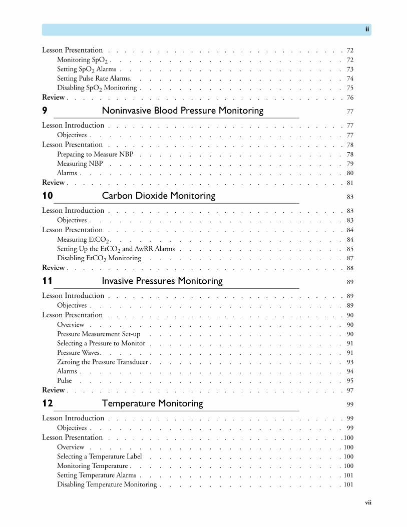
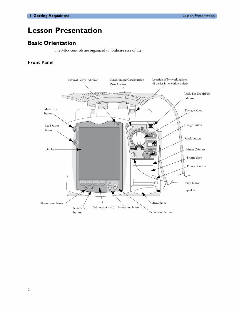
Basic OrientationThe MRx controls are organized to facilitate ease of use.
Front Panel
Sync
Shock
Charge
SelectEnergy 1
150
200
170120100
7050
30
20
15
1-10
AdultDose
Off On
AEDOn
M onitor
Pacer
3
2
Man
ual D
efib
Man
ual D
efib
Synchronized Cardioversion
(Sync) Button
Ready For Use (RFU)
Indicator
Therapy Knob
Charge button
Shock button
Printer (50mm)
Printer door latch
Speaker
Menu Select button
Navigation buttonsSoft keys (4 total)
Lead Select
button
Mark Event
button
Display
Print button
Printer door
External Power Indicator
Summary
button
Alarm Pause button Microphone
Location of Networking icon(if device is network enabled)
2

Lesson Presentation 1 Getting Acquainted
Notes:
________________________________________________________________
________________________________________________________________
________________________________________________________________
________________________________________________________________
________________________________________________________________
________________________________________________________________
________________________________________________________________
________________________________________________________________
________________________________________________________________
________________________________________________________________
3
1 Getting Acquainted Lesson Presentation
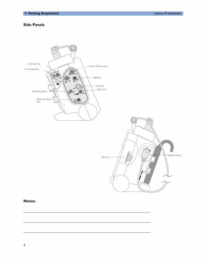
Side Panels
Notes:
________________________________________________________________
________________________________________________________________
________________________________________________________________
2
1
ECG
ECG
Microstream
CO 2
™
CO2 Inlet Port
CO2 Outlet Port
ECG Out (Sync) Jack
NBP Port
ECG Port
SpO2 Port
Invasive Pressure ports
Temperature Port
Data CardTherapy Connector
4
Lesson Presentation 1 Getting Acquainted
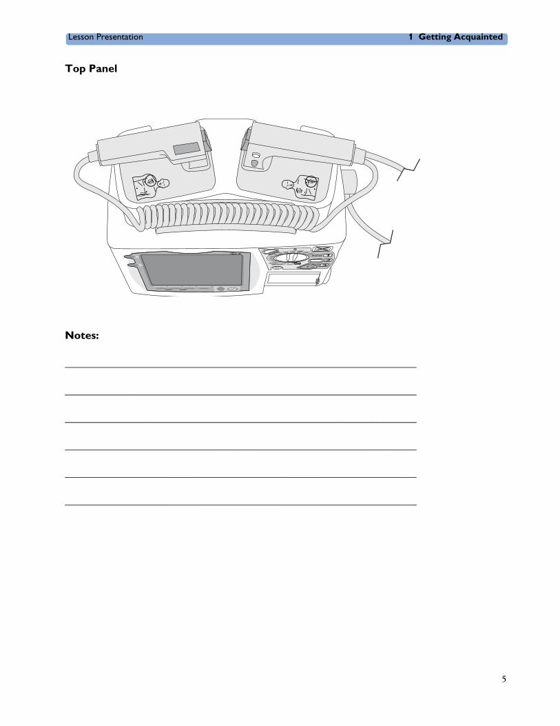
Top Panel
Notes:
________________________________________________________________
________________________________________________________________
________________________________________________________________
________________________________________________________________
________________________________________________________________
________________________________________________________________
5

1 Getting Acquainted Lesson Presentation
Back Panel
Notes:
________________________________________________________________
________________________________________________________________
________________________________________________________________
________________________________________________________________
________________________________________________________________
________________________________________________________________
Battery/AC Compartment B
LAN Connection
RS 232 Serial Port
AC Power ModuleDC Power Input
Battery
Battery Compartment A
Bed Rail Hook Mount
6
Lesson Presentation 1 Getting Acquainted
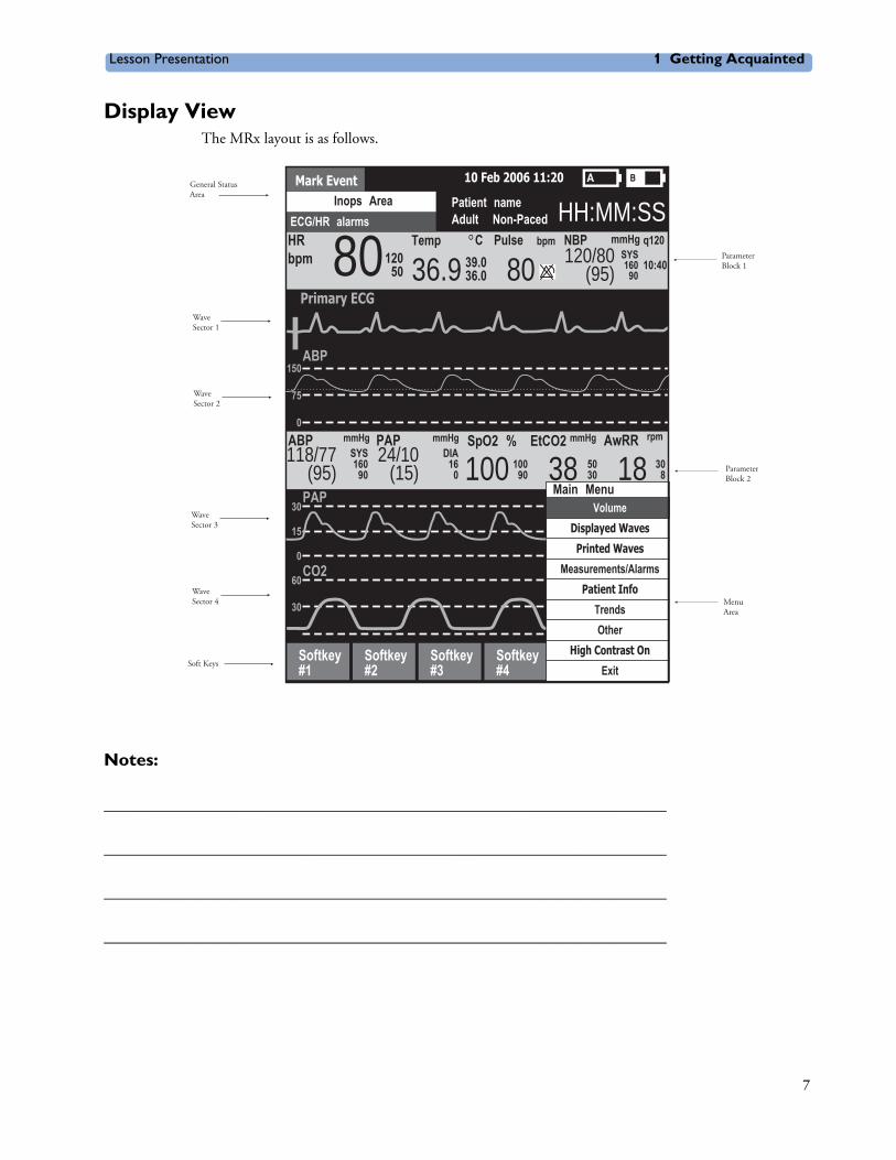
Display ViewThe MRx layout is as follows.
Notes:
________________________________________________________________
________________________________________________________________
________________________________________________________________
________________________________________________________________
ECG/HR alarms
Mark Event 10 Feb 2006 11:20
Patient nameAdult Non-Paced
Inops AreaHH:MM:SS
36.9 80 120/80(95)
Pulse NBP mmHg q120
10:40
bpm CTempSYS160
90
Primary ECG
HRbpm 80120
50 39.036.0
SpO2 % EtCO2
100AwRRmmHg rpmPAP ABP
150
75
0
ABP
PAP30
15
0CO2
60
30
0
160SYS118/77
(95)
mmHgmmHg
9024/10
(15) 16DIA
0100
90 38 5030 18 30
8
Softkey#1
Softkey#2
Softkey#3
Softkey#4
Main Menu
ExitHigh Contrast On
OtherTrends
Patient Info
Measurements/AlarmsPrinted Waves
Displayed Waves
Volume
Menu Area
Parameter Block 2
Parameter Block 1
Soft Keys
WaveSector 4
WaveSector 3
WaveSector 2
WaveSector 1
General StatusArea
7

1 Getting Acquainted Lesson Presentation
Responding to AlarmsFollow the steps below to respond to an alarm condition.
1. Attend to the patient.
2. Identify the alarm(s) indicated.
3. Silence the alarm(s) using the Navigation and Menu Select buttons.
4. Address the alarm condition.
Notes:
________________________________________________________________
________________________________________________________________
________________________________________________________________
________________________________________________________________
________________________________________________________________
8
Lesson Presentation 1 Getting Acquainted
Password SecurityAccess to Manual Defib and Pacer Modes may be password protected if enabled in Configuration. Failure to enter the correct Manual Therapy Security password prevents manual defibrillation/synchronized cardioversion delivery or pacing therapy. AED Mode is always available without a password.
Printing WaveformsTo change wave forms for the second wave printed with a 50mm printer:
1. Press the Menu Select button.
2. Using the Navigation buttons, select the Printed Waves option and press Menu Select.
3. Using the Navigation buttons, select the wave form you want to print in Wave 2 and press Menu Select.
To change wave forms for the second or third wave printed with a 75mm printer:
1. Press the Menu Select button.
2. Using the Navigation buttons, select the Printed Waves option and press Menu Select.
3. Using the Navigation buttons, select Wave 2 or Wave 3 and press Menu Select.
4. Using the Navigation buttons, select the wave form you want printed and press Menu Select.
5. Repeat Steps 2 through 4 for the other printed wave.
Continued UseMRx’s Continued Use feature facilitates continued treatment of the same patient by retaining current settings and the patient record when the MRx is turned off for less than 10 seconds or switching between modes (e.g., Monitor, AED, and Manual Defib).
9

1 Getting Acquainted Lesson Presentation
Return to OwnerTo enable the Return to Owner feature:
1. Press the Menu Select button.
2. Select Other and press Menu Select.
3. Select Return To Owner and press Menu Select.
4. Press the [Activate] soft key.
5. Enter the number of days in the loan period and press Menu Select.
6. Press the [Exit Return-To] soft key.
To disable the Return to Owner feature:
1. Press the Menu Select button.
2. Select Other and press Menu Select.
3. Select Return To Owner and press Menu Select.
4. Press the [Deactivate] soft key.
5. Enter the password and press Menu Select.
6. Press the [Exit Return-To] soft key.
Notes:
________________________________________________________________
________________________________________________________________
________________________________________________________________
________________________________________________________________
________________________________________________________________
10
Lesson Presentation 1 Getting Acquainted
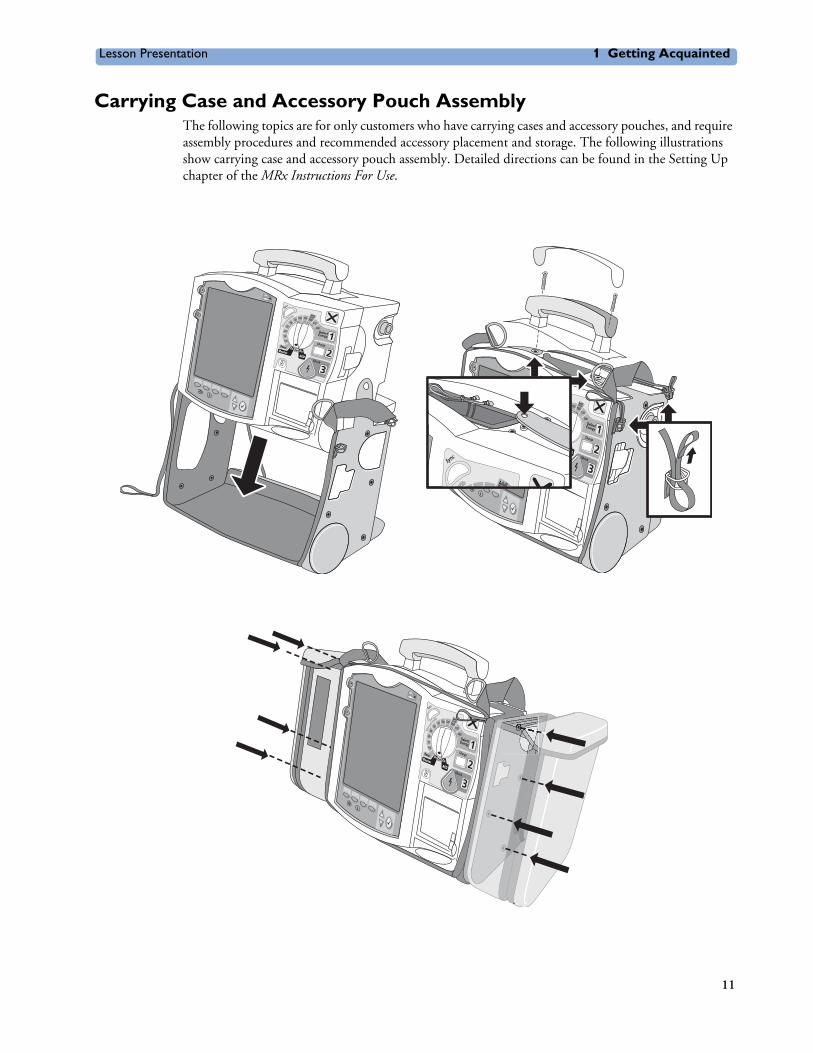
Carrying Case and Accessory Pouch AssemblyThe following topics are for only customers who have carrying cases and accessory pouches, and require assembly procedures and recommended accessory placement and storage. The following illustrations show carrying case and accessory pouch assembly. Detailed directions can be found in the Setting Up chapter of the MRx Instructions For Use.
11
1 Getting Acquainted Lesson Presentation
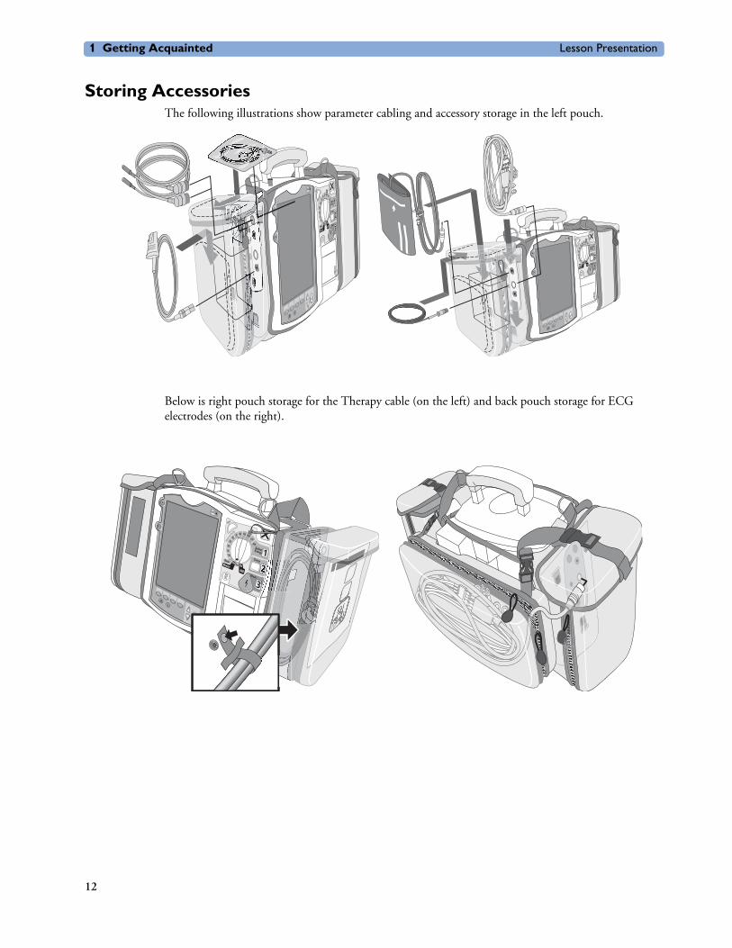
Storing AccessoriesThe following illustrations show parameter cabling and accessory storage in the left pouch.
Below is right pouch storage for the Therapy cable (on the left) and back pouch storage for ECG electrodes (on the right).
(((((((((((((((((((((((((
((((((((
((((((((
((((((((
((((((((((((((((
((((((((((((((((((((
((((((((((((((((((((
((((((((((((((((((
((((((((((((((((
((((((((((((((((((
((((((((((((((((((((
(((((
(((((((((((((((((((((((((((((
((((((((
((((((((
((((((((
((((((((((((((((((
((((((((
((((((((
((((((((
((((((((
((((((((
((((((((
((((((((
((((((((
((((((((
((((((((((((
((((((((((((((((((((
(((((((((((((((((((((
((((((((((((((((((((
((((((((((((((((((
((((((((((((((((
((((((((((((((((
((((((((((((((((
((((((((((((((((((((
((((((((((((((((((((
((((((((((((((((((((
((((((((((((((((((((
(((((((((((((((((((((
((((((((((((((((((((((
((((((((((((((((((((((((((((((((((((((
((((
((((
((((
((((
((((
((((
((((
((((
((((
((((
((
((((((((((((
((((((((
((((((((
((((((((
((((((((
((((((((
((((((((
(((
(((((
((((
((((
((((
(((((((
(((((
(((((((
(((((((((((
((((
(((((
((((((
((((((((
(((((
(((((
((((((
(((
(( (((((
(((((((((((((((((((((((((((
((((((((((((((((((((((((((((
(((((((((((((((((((((((((((((((((((((((((((((((((((((((((((((((((((((((((((((((((((((((((((((((((((((((((((((((((((((((((((((((((((((((((((((((((((((((((((((((((((((((((((((((((((((((((((((((((((((((((((((((((((((((((((((((((((((((((((((((((((((((((((((((((((((((((((((((((((((((((((((((((((((((((((((((((((((((((((((((((((((((((((((((((((((((((((((((((((((((((((((((((((((((((((((((((((((((((((((((((((((((((((((((((((((((( ((((((((((((((((((((((((((((((((((((((((((((
((((((((((((((((((((((((((((((((((((((((((((
((((((((((((((((((((((((((((((((((((((((((((((((
((((((((((((((((
((((((((((((
((((((((( (( (((( ((( ((( (( (((( ((( ((((((( (( (((( ((( ((((((((((((((((((( (( (((( ((( ((((((((((((((((((( (( (((( ((( ((((((((((((((((((((((
((((( (( (((( ((( ((((((((
((
((((
(((
(( (( (((( ((( (((((((((
((((
(((
((( (( (((( ((( ((
(((((((((((((((((((((((((((((
((((((((((((
((((((((((((
(((((((((
((((((((((((
((((((((((((
((((((
(((((
((((((((((((((((((((((((((( (((( ((((((((((((((( (((( (((((((((((((((((((((((((((((((((((((((((((((((((
(((((((((((((((
(((((((((((((((((((((((((((((((((((((((((((((((((((((((((((((((((((((((((((((((((((((((((((((((((((((((((((((((((((((((((((((((((((((((((((((((((((((((((((((((((((((((((((((((((((((((((((((((((((((((((((((((((((((((((((((((((((((((((((((((((((((((((((((((((((((((((((((((((((((((((((((((((((((((((((((((((((((
(((((((((((((((((((((((( (((( ((((((((
((((
((( (((( (((((((((((
(((( (((( (((
(((((((((((((((((((((((((
(
(((((((((((((((
(
(((((((((((
(((((((((((((((((((((((((
((((((((((((
((((((((((((
((((((((((((
(((((((((
(((((
(
(((((((((((((((((((((((((((((( (((( ((((((((((((((( (((( ((((((((((((((( (((( (((((((
(((((((((((((((((((((((((((((((
(((((((((
((((((((((((((((((((((((((((((((((((((((((((((((((((((((((((((((((((((((((((((((((((((((((((((((((((((((((((((((((((((((((((((((((((((((((((((((((((((((((((((((((((((((((((((((((((((((((((((((((((((((((((((((((((((((((((((((((((((((((((((((((((((((((((((((((((((((((((((((((((((((((((((((((((((((((((((((((((((((
(((((((((( (((( ((((((((
((((
((( (((( ((((((((
((((
((( (((( (((((((((((
(((( (((( (((
((((((((((((((((((((((((
((((((((((((((((((((((((
((((((((((((
((((((((((((
(((
(((((
(
((((((((((((((((((((((((((((((((((((( (((( ((((((((((((((( (((( ((((((((((((((( (((( ((((((((((((((((((((((((((((((((((
((((((((((((
((((((((((((((((((((((((((((((((((((((((((((((((((((((((((((((((((((((((((((((((((((((((((((((((((((((((((((((((((((((((((((((((((((((((((((((((((((((((((((((((((((((((((((((((((((((((((((((((((((((((((((((((((((((((((((((((((((((((((((((((((((((((((((((((((((((((((((((((((((((((((((((((((((((((((((((((((((((((((((((
((((((((((((((((((((
((((
((( (((( ((((((((
((((
((( (((( (((((((((((
(((( (((( (((
12
Lesson Presentation 1 Getting Acquainted
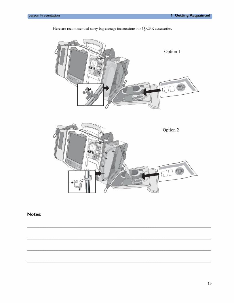
Here are recommended carry bag storage instructions for Q-CPR accessories.
Notes:
________________________________________________________________________________
________________________________________________________________________________
________________________________________________________________________________
________________________________________________________________________________
PHILIPS
PHILIPS
Option 1
Option 2
13

1 Getting Acquainted Review
ReviewPlease answer the following questions related to MRx features, controls, and display view.
1. Identify at least three controls or buttons on the MRx involved with defibrillation.
a. ______________________________________
b. ______________________________________
c. ______________________________________
2. What does a solid red "X" and periodic audio chirp indicate on the RFU?
a. No battery is present
b. No power is available
c. A low battery condition
d. Defibrillation therapy may not be available
3. The arrhythmia algorithm uses the ECG in which Wave Sector for analysis?
a. 1
b. 2
c. 3
d. all of the above
4. You can select the ECG lead for Wave Sector 2 using either the Lead Select button or Displayed Waves menu. T or F
5. You should respond to alarms primarily by pressing the Alarm Pause button. T or F
14

2
User Training Workbook
2ECG and ArrhythmiaMonitoring
Lesson IntroductionThis lesson describes the basic ECG and arrhythmia monitoring functions of the HeartStart MRx. It briefly examines Monitor View, monitoring preparation, alarms, annotated ECGs, and arrhythmia learning/relearning.
ObjectivesUpon completion of this lesson, you should be able to:
1. Locate pertinent information in Monitor View.
2. Prepare a patient for ECG and arrhythmia monitoring.
3. Set heart rate and arrhythmia alarms.
4. Display an annotated ECG.
5. Initiate manual relearning.
Notes:
________________________________________________________________
________________________________________________________________
________________________________________________________________
________________________________________________________________
________________________________________________________________
________________________________________________________________
15
2 ECG and Arrhythmia Monitoring Lesson Presentation
Lesson Presentation
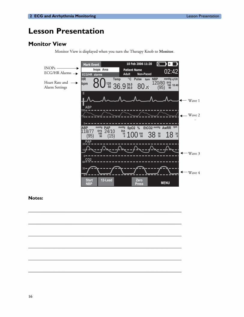
Monitor ViewMonitor View is displayed when you turn the Therapy Knob to Monitor.
Notes:
________________________________________________________________
________________________________________________________________
________________________________________________________________
________________________________________________________________
________________________________________________________________
________________________________________________________________
ECG/HR alarms
Mark Event 10 Feb 2006 11:20
Patient NameAdult Non-Paced
Inops Area 02:42
36.9 80 120/80(95)
Pulse NBP mmHg q120
10:40
bpm CTempSYS160
90
II
HRbpm 80120
50 39.036.0
SpO2 % EtCO2
100AwRRmmHg rpmPAP ABP
150
75
0
ABP
PAP30
15
0CO2
60
30
0
160SYS118/77
(95)
mmHgmmHg
9024/10
(15) 16DIA
0100
90 38 5030 18 30
8
StartNBP
12-Lead ZeroMENUPress
INOPsECG/HR Alarms
Heart Rate and Alarm Settings
Wave 1
Wave 2
Wave 3
Wave 4
16

Lesson Presentation 2 ECG and Arrhythmia Monitoring
PreparationFollow the steps below to prepare for monitoring using multifunction electrode pads or electrodes.
Multifunction electrode pads1. Prepare the patient’s chest (i.e., remove clothing, remove moisture from chest, and remove excessive
hair).
2. Apply multifunction electrode pads to the patient according to the pads package directions or your organization’s protocol.
3. If not pre-connected, insert the pads cable into MRx’s green Therapy port.
4. Connect the pads to the pads cable.
Electrodes1. Prepare the patient’s skin at appropriate electrode sites.
– If necessary, clip hair at the electrode sites (or shave sites if needed).
– Clean and abrade the skin at each electrode site.
– Dry the electrode sites briskly to increase capillary blood flow in the tissues and to remove oil and skin cells.
2. Attach the snaps to the electrodes.
3. Apply the electrodes.
4. If not pre-connected, connect the ECG patient cable to the MRx.
Lead SelectionUse the Lead Select button to select the ECG lead for Wave Sector 1. To select a lead for Wave Sectors 2-4:
1. Press the Menu Select button.
2. Select Displayed Waves and press Menu Select.
3. Select the appropriate Wave Sector and press Menu Select.
4. Select the desired lead (with the clearest signal) and press Menu Select.
17

2 ECG and Arrhythmia Monitoring Lesson Presentation
Practice Exercise 1Attach a simulator and 3-, 5-, and 10-Lead ECG set to the MRx (5- or 10-Lead set preferred), set the simulator to a normal sinus rhythm, and complete a variety of lead selections for Wave Sectors 2, 3, and 4, as appropriate.
Questions
1. How do Wave 2, 3, and/or 4 menus differ from each other in terms of available leads? From the Wave 1 menu?
2. What wave size(s) provide the clearest wave form?
3. What happens if you add a parameter?
Notes:
________________________________________________________________
________________________________________________________________
________________________________________________________________
________________________________________________________________
________________________________________________________________
18
Lesson Presentation 2 ECG and Arrhythmia Monitoring
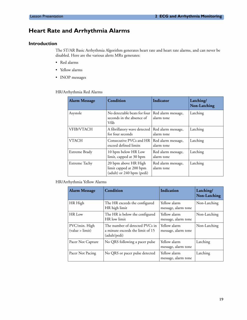
Heart Rate and Arrhythmia Alarms
IntroductionThe ST/AR Basic Arrhythmia Algorithm generates heart rate and heart rate alarms, and can never be disabled. Here are the various alerts MRx generates:
• Red alarms
• Yellow alarms
• INOP messages
HR/Arrhythmia Red Alarms
HR/Arrhythmia Yellow Alarms
Alarm Message Condition Indicator Latching/Non-Latching
Asystole No detectable beats for four seconds in the absence of Vfib
Red alarm message, alarm tone
Latching
VFIB/VTACH A fibrillatory wave detected for four seconds
Red alarm message, alarm tone
Latching
VTACH Consecutive PVCs and HR exceed defined limits
Red alarm message, alarm tone
Latching
Extreme Brady 10 bpm below HR Low limit, capped at 30 bpm
Red alarm message, alarm tone
Latching
Extreme Tachy 20 bpm above HR High limit capped at 200 bpm (adult) or 240 bpm (pedi)
Red alarm message, alarm tone
Latching
Alarm Message Condition Indication Latching/Non-Latching
HR High The HR exceeds the configured HR high limit
Yellow alarm message, alarm tone
Non-Latching
HR Low The HR is below the configured HR low limit
Yellow alarm message, alarm tone
Non-Latching
PVC/min. High(value > limit)
The number of detected PVCs in a minute exceeds the limit of 15 (adult/pedi)
Yellow alarm message, alarm tone
Non-Latching
Pacer Not Capture No QRS following a pacer pulse Yellow alarm message, alarm tone
Latching
Pacer Not Pacing No QRS or pacer pulse detected Yellow alarm message, alarm tone
Latching
19
2 ECG and Arrhythmia Monitoring Lesson Presentation
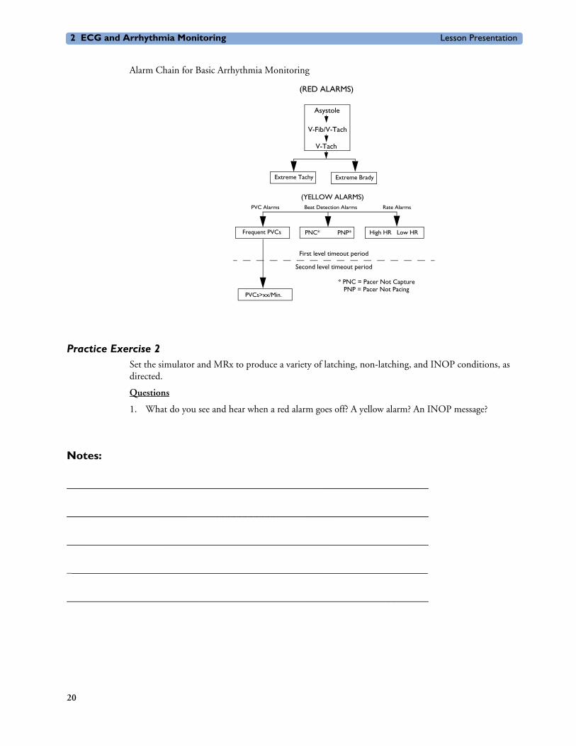
Alarm Chain for Basic Arrhythmia Monitoring
Practice Exercise 2Set the simulator and MRx to produce a variety of latching, non-latching, and INOP conditions, as directed.
Questions
1. What do you see and hear when a red alarm goes off? A yellow alarm? An INOP message?
Notes:
________________________________________________________________
________________________________________________________________
________________________________________________________________
________________________________________________________________
________________________________________________________________
(RED ALARMS)
Asystole
V-Fib/V-Tach
Extreme Tachy Extreme Brady
(YELLOW ALARMS)
PNC* PNP*
V-Tach
Beat Detection Alarms Rate AlarmsPVC Alarms
First level timeout period
Second level timeout period
Frequent PVCs High HR Low HR
PVCs>xx/Min.
* PNC = Pacer Not Capture PNP = Pacer Not Pacing
20
Lesson Presentation 2 ECG and Arrhythmia Monitoring
Setting Alarms• Alarms are automatically enabled in Monitor and Pacer Modes.
• In Manual Defib Mode, alarms are automatically enabled if the Sync function is enabled. If the Sync function is not enabled, alarms are enabled using the Alarm Pause button.
• Alarms alert you when values exceed or fall below defined limits.
• Heart rate (HR) and VTACH alarm settings are as configured but may be changed during operation for the current patient.
• The PVC rate limit setting may only be changed in response to a PVC rate alarm condition.
• Other HR and arrhythmia alarms may not be changed.
Changing Heart Rate or VTACH Alarm LimitsTo change HR or VTACH limits:
1. Press the Menu Select button.
2. Select Measurements/Alarms and press Menu Select.
3. Select HR/Arrhythmia and press Menu Select.
4. Select HR Limits and press Menu Select.
5. Select new values and press Menu Select.
6. Select VTACH Limits and press Menu Select.
7. Select new values and press Menu Select.
Enabling/Disabling Heart Rate and Arrhythmia AlarmsTo enable or disable HR and arrhythmia alarms:
1. Press Menu Select.
2. Select Measurements/Alarms and press Menu Select.
3. Select HR/Arrhythmia and press Menu Select.
4. Select Alarms On/Off and press Menu Select.
Note: Disabling alarms prevent all alarms associated with HR measurements from being annunciated. If an alarm condition occurs, no alarm indication will be given.
Responding to HR and Arrhythmia AlarmsTo respond to the Audio Pause label, press the Menu Select or Navigation buttons.
To respond to alarms:
1. Acknowledge the alarm condition.
2. Adjust the limits using the New Limits menu.
21

2 ECG and Arrhythmia Monitoring Lesson Presentation
Practice Exercise 3Change HR or VTACH limits, enable or disable alarms, and respond to HR and arrhythmia alarms.
Questions
1. What happens when you change a limit? Disable an alarm? Respond to the Audio Pause label or an alarm?
Notes:
________________________________________________________________
________________________________________________________________
________________________________________________________________
________________________________________________________________
________________________________________________________________
Displaying an Annotated ECG An annotated wave displays how the ST/AR Algorithm labels beats. To display an annotated ECG:
1. Press Menu Select.
2. Select Displayed Waves and press Menu Select.
3. Select Wave 2 and press Menu Select.
4. Select Annotated ECG and press Menu Select.
Practice Exercise 4Complete the steps to display an annotated ECG.
Question
Where does the annotation first appear?
Notes:
________________________________________________________________
________________________________________________________________
________________________________________________________________
22

Lesson Presentation 2 ECG and Arrhythmia Monitoring
Arrhythmia Learning/RelearningMRx automatically performs arrhythmia learning/relearning when the lead or mode of operation is changed so the ST/AR Algorithm can properly analyze the patient’s normal and/or paced complexes.
Initiate manual relearning if beat detection is not occurring or if beat classification is incorrect and results in a false alarm. To initiate relearning manually:
1. Press Menu Select.
2. Select Measurements/Alarms and press Menu Select.
3. Select HR/Arrhythmia and press Menu Select.
4. Select Relearn Rhythm and press Menu Select.
Practice Exercise 5Complete the steps to initiate manual relearning.
Notes:
________________________________________________________________
________________________________________________________________
________________________________________________________________
________________________________________________________________
________________________________________________________________
23
2 ECG and Arrhythmia Monitoring Review
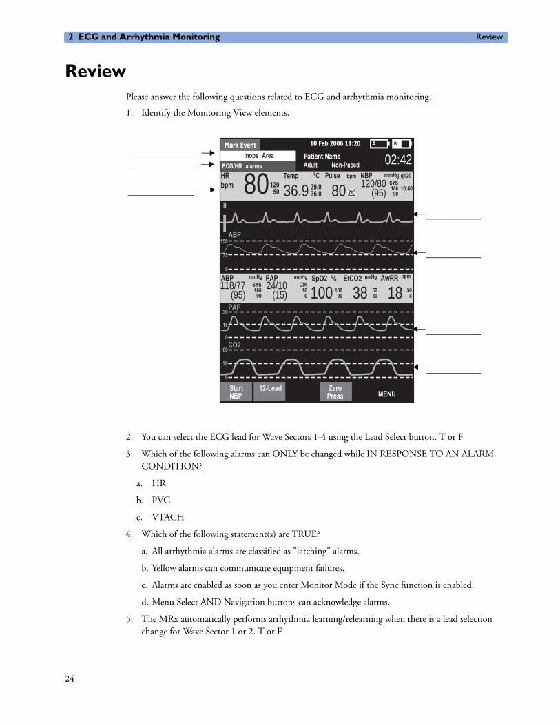
ReviewPlease answer the following questions related to ECG and arrhythmia monitoring.
1. Identify the Monitoring View elements.
2. You can select the ECG lead for Wave Sectors 1-4 using the Lead Select button. T or F
3. Which of the following alarms can ONLY be changed while IN RESPONSE TO AN ALARM CONDITION?
a. HR
b. PVC
c. VTACH
4. Which of the following statement(s) are TRUE?
a. All arrhythmia alarms are classified as "latching" alarms.
b. Yellow alarms can communicate equipment failures.
c. Alarms are enabled as soon as you enter Monitor Mode if the Sync function is enabled.
d. Menu Select AND Navigation buttons can acknowledge alarms.
5. The MRx automatically performs arrhythmia learning/relearning when there is a lead selection change for Wave Sector 1 or 2. T or F
ECG/HR alarms
Mark Event 10 Feb 2006 11:20
Patient NameAdult Non-Paced
Inops Area 02:42
36.9 80 120/80(95)
Pulse NBP mmHg q120
10:40
bpm CTempSYS160
90
II
HRbpm 80120
50 39.036.0
SpO2 % EtCO2
100AwRRmmHg rpmPAP ABP
150
75
0
ABP
PAP30
15
0CO2
60
30
0
160SYS118/77
(95)
mmHgmmHg
9024/10
(15) 16DIA
0100
90 38 5030 18 30
8
StartNBP
12-Lead ZeroMENUPress
__________
__________
__________
__________
________________________
____________
24

3
User Training Workbook
3Semi-Automated ExternalDefibrillation
Lesson IntroductionThis lesson describes how to use AED Mode. It highlights the AED display view and explains the steps and associated prompts that guide users through the defibrillation process.
ObjectivesUpon completion of this lesson, you should be able to:
1. Locate pertinent information in AED View.
2. Prepare a patient for AED defibrillation.
3. Defibrillate in AED Mode.
Notes:
________________________________________________________________
________________________________________________________________
________________________________________________________________
________________________________________________________________
________________________________________________________________
25
3 Semi-Automated External Defibrillation Lesson Presentation
Lesson Presentation
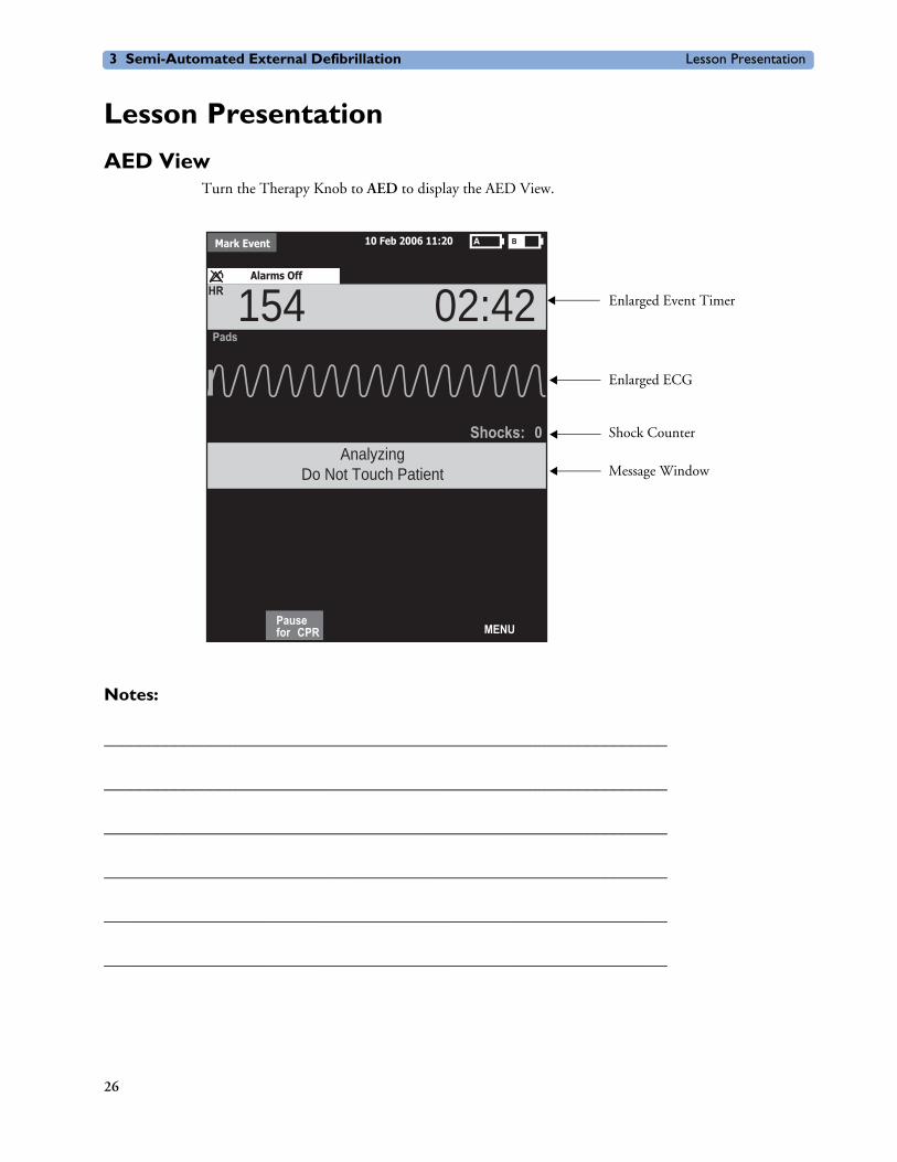
AED ViewTurn the Therapy Knob to AED to display the AED View.
Notes:
________________________________________________________________
________________________________________________________________
________________________________________________________________
________________________________________________________________
________________________________________________________________
________________________________________________________________
Alarms Off
Mark Event 10 Feb 2006 11:20
Pads
HR 154 02:42
AnalyzingDo Not Touch Patient
Pausefor CPR MENU
Shocks: 0
Enlarged Event Timer
Enlarged ECG
Shock Counter
Message Window
26

Lesson Presentation 3 Semi-Automated External Defibrillation
PreparationTo prepare for AED defibrillation:
1. Confirm the patient’s condition (i.e., unresponsive, not breathing, and/or pulseless).
2. Prepare the patient’s chest.
3. Apply multifunction electrode pads using the anterior-anterior electrode placement.
4. If not pre-connected, insert the pads cable into the green Therapy port.
5. Connect the pads to the pads cable.
Notes:
________________________________________________________________
________________________________________________________________
________________________________________________________________
________________________________________________________________
________________________________________________________________
________________________________________________________________
27

3 Semi-Automated External Defibrillation Lesson Presentation
AED ModeTo defibrillate in AED Mode:
1. Turn the Therapy Knob to AED.
2. Follow the voice and screen prompts.
3. Press the orange Shock button, if prompted.
Practice Exercise 1Turn the Therapy Knob to AED and to see what happens when your pads cable and/or pads are not connected.
Notes:
________________________________________________________________
________________________________________________________________
________________________________________________________________
________________________________________________________________
________________________________________________________________
________________________________________________________________
28

Lesson Presentation 3 Semi-Automated External Defibrillation
Shock Advised
Practice Exercise 2Attach an ECG simulator to the MRx via a hands-free (pads) cable, set the simulator to a shockable rhythm (e.g., VF), and follow the steps to defibrillate. Complete one shock.
Questions
1. What screen prompts do you see and voice prompts do you hear initially?
2. How do you know the device is ready to deliver a charge?
3. What do you see and hear after delivering a shock?
4. What happens when you press the [Resume Analyzing] soft key?
Notes:
________________________________________________________________
________________________________________________________________
________________________________________________________________
________________________________________________________________
________________________________________________________________
________________________________________________________________
29

3 Semi-Automated External Defibrillation Lesson Presentation
No Shock Advised
Practice Exercise 3Set the simulator to a normal sinus rhythm and see what happens.
Questions
1. What screen prompts do you see and voice prompts do you hear?
2. What happens when you press the [Pause for CPR] soft key?
Notes:
________________________________________________________________
________________________________________________________________
________________________________________________________________
________________________________________________________________
________________________________________________________________
________________________________________________________________
30
Review 3 Semi-Automated External Defibrillation
ReviewPlease answer the following questions related to AED.
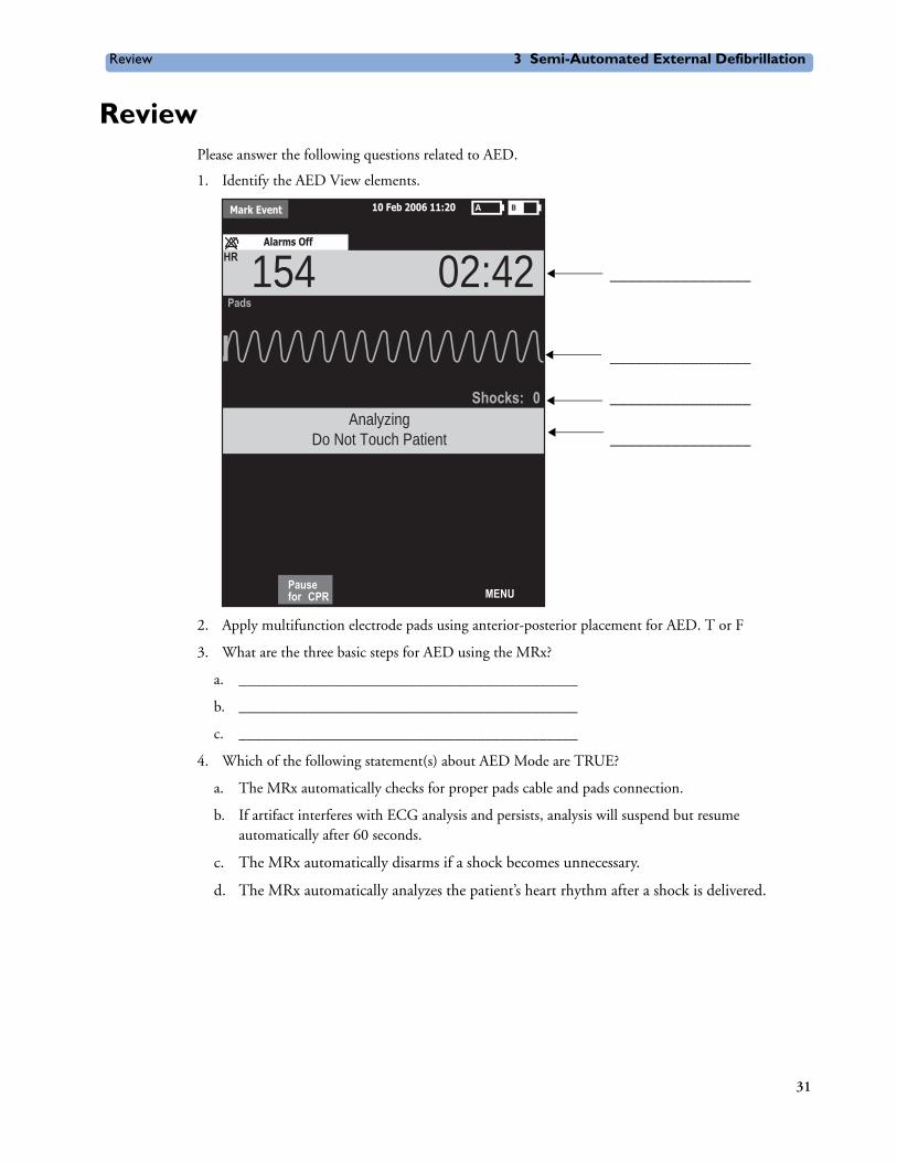
1. Identify the AED View elements.
2. Apply multifunction electrode pads using anterior-posterior placement for AED. T or F
3. What are the three basic steps for AED using the MRx?
a. ____________________________________________
b. ____________________________________________
c. ____________________________________________
4. Which of the following statement(s) about AED Mode are TRUE?
a. The MRx automatically checks for proper pads cable and pads connection.
b. If artifact interferes with ECG analysis and persists, analysis will suspend but resume automatically after 60 seconds.
c. The MRx automatically disarms if a shock becomes unnecessary.
d. The MRx automatically analyzes the patient’s heart rhythm after a shock is delivered.
Alarms Off
Mark Event 10 Feb 2006 11:20
Pads
HR 154 02:42
AnalyzingDo Not Touch Patient
Pausefor CPR MENU
Shocks: 0
________________
________________
________________
________________
31


4
User Training Workbook
4Manual Defibrillationand Cardioversion
Lesson IntroductionThis lesson explains how to prepare for and perform manual asynchronous and synchronous (cardioversion) defibrillation using multifunction electrode pads and external/internal paddles.
ObjectivesUpon completion of this lesson, you should be able to:
1. Locate pertinent information in Code View.
2. Prepare a patient for asynchronous and synchronous defibrillation.
3. Perform asynchronous and synchronous defibrillation.
Notes:
________________________________________________________________
________________________________________________________________
________________________________________________________________
________________________________________________________________
________________________________________________________________
________________________________________________________________
33
4 Manual Defibrillation and Cardioversion Lesson Presentation
Lesson Presentation
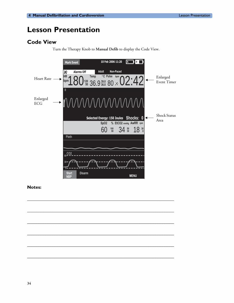
Code ViewTurn the Therapy Knob to Manual Defib to display the Code View.
Notes:
________________________________________________________________
________________________________________________________________
________________________________________________________________
________________________________________________________________
________________________________________________________________
________________________________________________________________
Mark Event 10 Feb 2006 11:20
36.9 CTemp
II
HR18012050
39.036.0
SpO2 % EtCO2
60AwRRmmHg rpm
Pleth
MENU
10090 34 50
30 18 308
StartNBP
Disarm
02:42Alarms Off
Shocks: 0
bpm
Adult Non-Paced
Selected Energy: 150 Joules
CO260
30
0
80Pulse bpm
Heart Rate
Enlarged ECG
Enlarged Event Timer
Shock Status Area
34

Lesson Presentation 4 Manual Defibrillation and Cardioversion
Manual Defibrillation PreparationFollow the steps below to prepare for manual defibrillation using multifunction electrode pads or external paddles.
Multifunction Electrode Pads1. Confirm the patient’s condition (i.e., unresponsive, not breathing, and/or pulseless).
2. Prepare the patient’s chest.
3. Apply multifunction electrode pads to the patient according to pads package directions or your organization’s protocol.
4. If not pre-connected, insert the pads cable into MRx’s green Therapy port.
5. Connect the pads to the pads cable.
External Paddles1. Confirm the patient’s condition (i.e., unresponsive, not breathing, and/or pulseless).
2. If not pre-connected, insert the paddles cable into the green Therapy port.
3. Remove the paddles from paddle tray. Clean any debris or residue (including dried electrode gel) off the surfaces of the paddles, if necessary.
4. Apply the paddles to patient’s bare chest, using the anterior-anterior placement or your organization’s protocol.
Internal Paddles1. Select the appropriate switched or switchless paddle electrode size.
2. If using switchless paddles, connect the paddles to the M4740A Paddle Adapter Cable.
3. Connect the paddles cable (or the paddle adapter cable) to the MRx.
Notes:
________________________________________________________________
________________________________________________________________
________________________________________________________________
________________________________________________________________
________________________________________________________________
________________________________________________________________
35

4 Manual Defibrillation and Cardioversion Lesson Presentation
Manual DefibrillationTo defibrillate in Manual Mode:
1. Turn the Therapy Knob to Manual Defib and select an energy setting.
2. Press the Charge button on the MRx (or external paddle).
3. Make sure no one is touching the patient or anything connected to the patient before shock; call out loudly and clearly “Stay Clear!”.
4. Press the orange Shock button on the MRx (or the shock buttons on the external or switched internal paddles).
Practice Exercise 1Attach a simulator and parameter accessories (if available and appropriate) to the MRx, set the simulator to a shockable rhythm (e.g., VF), and complete the manual defibrillation steps (with three shocks).
Questions
1. What do you see and hear during a charge?
2. How do you know the device is ready to deliver a charge?
3. What do you see and hear after delivering a shock?
4. What happens when you press the [Disarm] soft key?
Notes:
________________________________________________________________
________________________________________________________________
________________________________________________________________
________________________________________________________________
________________________________________________________________
________________________________________________________________
36

Lesson Presentation 4 Manual Defibrillation and Cardioversion
Synchronized Cardioversion PreparationFollow the steps below to prepare for synchronized cardioversion.
1. Perform the steps as described in the previous Manual Defibrillation Preparation topic.
2. If monitoring through a 3-, 5-, or 10-Lead ECG cable, plug the cable into MRx’s ECG port and apply monitoring electrodes to the patient.
3. Press the Lead Select button to select Pads, Paddles, or a lead from attached monitoring electrodes.
Notes:
________________________________________________________________
________________________________________________________________
________________________________________________________________
________________________________________________________________
________________________________________________________________
________________________________________________________________
37

4 Manual Defibrillation and Cardioversion Lesson Presentation
Synchronized Shock DeliveryTo deliver a synchronized shock:
1. Turn the Therapy Knob to Monitor position and press the Sync button.
2. Confirm that the Sync marker appears with each R-wave.
3. Turn the Therapy Knob to Manual Defib and select an energy setting.
4. Press the Charge button on the MRx (or external paddle).
5. Make sure no one is touching the patient or anything connected to the patient before shock; call out loudly and clearly “Stay Clear!”.
6. Press and hold the orange Shock button on the MRx (or the orange shock buttons on both paddles) until the shock is delivered.
Practice Exercise 2Attach a simulator and pads to the MRx, set the simulator to a shockable rhythm (e.g., VF), and complete synchronized cardioversion.
Questions
1. What do you see when you press the Sync button?
2. Once in Sync mode, what happens when you turn the Therapy Knob to a position other than Manual Defib?
3. What happens when you press the Sync button again?
Notes:
________________________________________________________________
________________________________________________________________
________________________________________________________________
________________________________________________________________
________________________________________________________________
________________________________________________________________
38
Review 4 Manual Defibrillation and Cardioversion
ReviewPlease answer the following questions related to manual defibrillation and synchronized cardioversion.
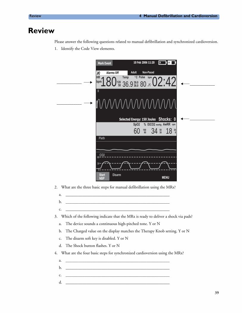
1. Identify the Code View elements.
2. What are the three basic steps for manual defibrillation using the MRx?
a. __________________________________________________
b. __________________________________________________
c. __________________________________________________
3. Which of the following indicate that the MRx is ready to deliver a shock via pads?
a. The device sounds a continuous high-pitched tone. Y or N
b. The Charged value on the display matches the Therapy Knob setting. Y or N
c. The disarm soft key is disabled. Y or N
d. The Shock button flashes. Y or N
4. What are the four basic steps for synchronized cardioversion using the MRx?
a. __________________________________________________
b. __________________________________________________
c. __________________________________________________
d. __________________________________________________
Mark Event 10 Feb 2006 11:20
36.9 CTemp
II
HR18012050
39.036.0
SpO2 % EtCO2
60AwRRmmHg rpm
Pleth
MENU
10090 34 50
30 18 308
StartNBP
Disarm
02:42Alarms Off
Shocks: 0
bpm
Adult Non-Paced
Selected Energy: 150 Joules
CO260
30
0
80Pulse bpm
____________
____________
____________
____________
39


5
User Training Workbook
5Q-CPR® with CPR meter
Lesson IntroductionThis lesson describes how to set-up and use the Q-CPR® option (with CPR meter) available on the HeartStart MRx.
Note: Q-CPR® is a trademark of Laerdal Medical AS.
ObjectivesUpon completion of this lesson, you should be able to:
1. Identify intended use and preparation for use related to Q-CPR.
2. Identify characteristics related to the CPR meter.
3. Identify characteristics related to Q-CPR in Manual Defib and AED Modes.
Notes:
________________________________________________________________
________________________________________________________________
________________________________________________________________
________________________________________________________________
________________________________________________________________
41

Lesson Presentation 5 Q-CPR® with CPR meter
Lesson Presentation
OverviewQ-CPR:
• Offers measurement and corrective feedback on:
– compression rate, depth, and complete release
– ventilation rate
– CPR inactivity
• Measures compressions through the CPR meter and acquires ventilation data through multifunction defib electrode pads
• Is used with only the HeartStart MRx
• Is not active in 12-Lead Mode
• Is not intended for use:
– on patients under 8 years of age or weighing less than 25 kg (55 lbs.)
– in a moving environment
– with any other CPR compression devices (aside from the CPR meter)
• Events related to Q-CPR are logged to the patient incident record but not stored in the MRx Event Summary.
Notes:
________________________________________________________________
________________________________________________________________
________________________________________________________________
________________________________________________________________
________________________________________________________________
42

Lesson Presentation 5 Q-CPR® with CPR meter
Q-CPR Preparation
Follow the steps below to prepare for Q-CPR use.
1. Connect the Pads/CPR cable to the MRx, aligning the white pointer on the cable with the white arrow on the green Therapy port, inserting the cable into the port, and pushing until you hear it click into place.
2. Connect the CPR meter to the Pads/CPR cable, aligning the key on the CPR meter cable with the key on the receptacle end of the Pads/CPR cable, and pushing until you feel it snap into place. There should be no gap between the two connectors.
3. Attach the CPR meter Adhesive Pad to the meter, aligning the channel on the adhesive is directly over the visible groove in the plastic and pressing the pad into place.
Note: Complete steps 1-3 before a rescue or resuscitation event to save time on set-up.
4. Prepare the patient’s chest and apply the multifunction electrode pads to the patient as directed on the pads package, using the anterior-anterior placement.
5. Connect the pads to the Pads/CPR cable.
6. Peel off the green liner from the CPR meter Adhesive Pad and position the CPR meter‘s compression area on the lower half of the sternum and on the centerline of the bare chest.
Notes:
________________________________________________________________
________________________________________________________________
________________________________________________________________
________________________________________________________________
________________________________________________________________
43

Lesson Presentation 5 Q-CPR® with CPR meter
Starting CPR with the CPR meterUse standard CPR technique and observe the CPR meter display area for feedback (See figure below). Provide chest compressions according to your organization’s CPR protocol.
Figure 1 CPR and Positioning
The display changes to enlarged compression indicators when the meter first detects compressions (as depicted blow).
Figure 2 Beginning Compressions on CPR meter
44
Lesson Presentation 5 Q-CPR® with CPR meter
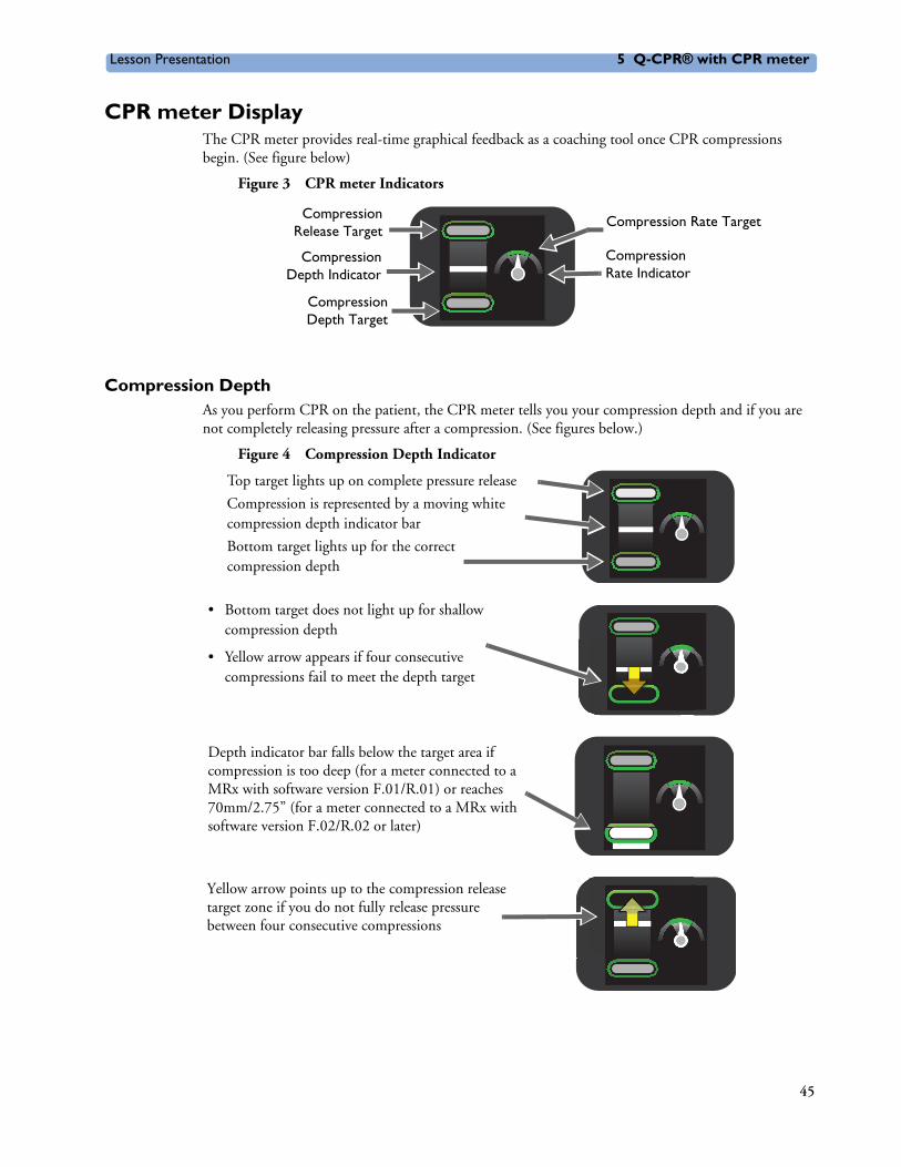
CPR meter DisplayThe CPR meter provides real-time graphical feedback as a coaching tool once CPR compressions begin. (See figure below)
Figure 3 CPR meter Indicators
Compression DepthAs you perform CPR on the patient, the CPR meter tells you your compression depth and if you are not completely releasing pressure after a compression. (See figures below.)
Figure 4 Compression Depth Indicator
Compression Rate Target
Compression Rate Indicator
CompressionRelease Target
CompressionDepth Indicator
CompressionDepth Target
Top target lights up on complete pressure release
Compression is represented by a moving white compression depth indicator bar
Bottom target lights up for the correct compression depth
Depth indicator bar falls below the target area if compression is too deep (for a meter connected to a MRx with software version F.01/R.01) or reaches 70mm/2.75” (for a meter connected to a MRx with software version F.02/R.02 or later)
Yellow arrow points up to the compression release target zone if you do not fully release pressure between four consecutive compressions
• Bottom target does not light up for shallow compression depth
• Yellow arrow appears if four consecutive compressions fail to meet the depth target
45
Lesson Presentation 5 Q-CPR® with CPR meter
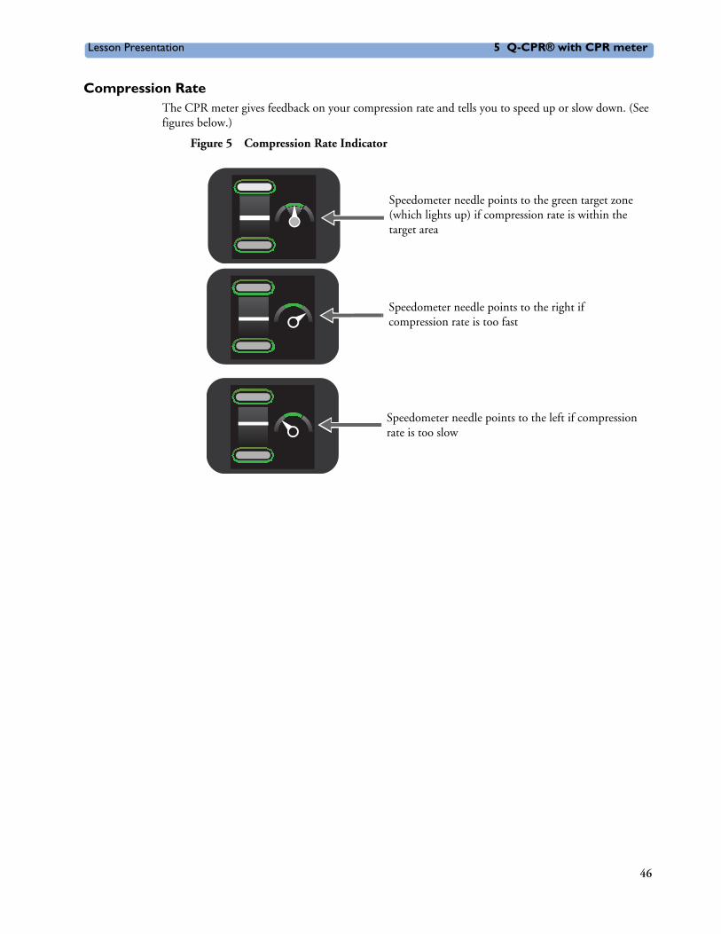
Compression RateThe CPR meter gives feedback on your compression rate and tells you to speed up or slow down. (See figures below.)
Figure 5 Compression Rate Indicator
Speedometer needle points to the green target zone (which lights up) if compression rate is within the target area
Speedometer needle points to the right if compression rate is too fast
Speedometer needle points to the left if compression rate is too slow
46
Lesson Presentation 5 Q-CPR® with CPR meter
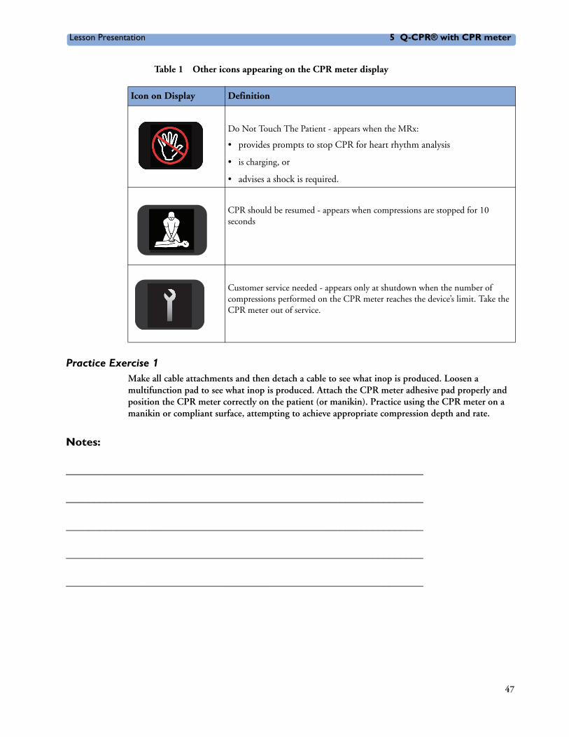
Table 1 Other icons appearing on the CPR meter display
Practice Exercise 1Make all cable attachments and then detach a cable to see what inop is produced. Loosen a multifunction pad to see what inop is produced. Attach the CPR meter adhesive pad properly and position the CPR meter correctly on the patient (or manikin). Practice using the CPR meter on a manikin or compliant surface, attempting to achieve appropriate compression depth and rate.
Notes:
________________________________________________________________
________________________________________________________________
________________________________________________________________
________________________________________________________________
________________________________________________________________
Icon on Display Definition
Do Not Touch The Patient - appears when the MRx:
• provides prompts to stop CPR for heart rhythm analysis
• is charging, or
• advises a shock is required.
CPR should be resumed - appears when compressions are stopped for 10 seconds
Customer service needed - appears only at shutdown when the number of compressions performed on the CPR meter reaches the device’s limit. Take the CPR meter out of service.
47
Lesson Presentation 5 Q-CPR® with CPR meter
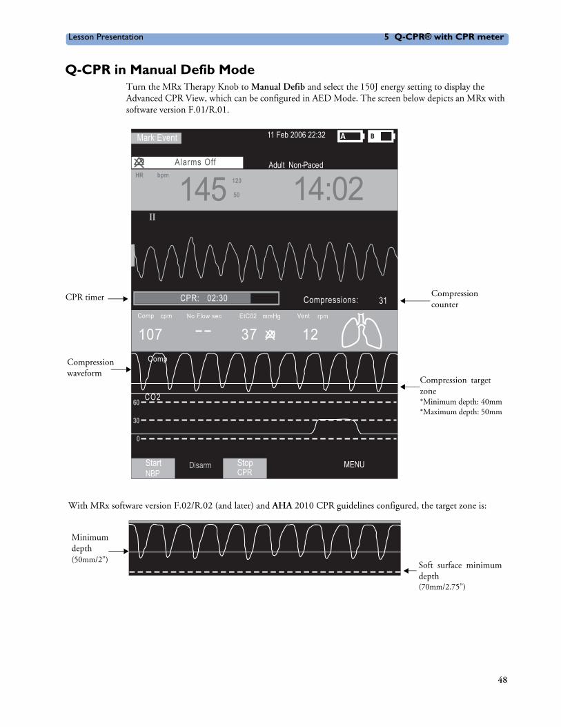
Q-CPR in Manual Defib ModeTurn the MRx Therapy Knob to Manual Defib and select the 150J energy setting to display the Advanced CPR View, which can be configured in AED Mode. The screen below depicts an MRx with software version F.01/R.01.
With MRx software version F.02/R.02 (and later) and AHA 2010 CPR guidelines configured, the target zone is:
11 Feb 2006 22:32
Adult Non- PacedAlarms OffHRHR
145 14:02120120
5050
StartNBP
Disarm MENUStopCPR
bpm
Mark Event
107cpm
CO2
12Vent rpm CompComp
Comp
Compressions: 31No Flow sec
II
EtC02 mmHg
37
60
30
0
CPR: 02:30
Compressionvtargetzone *Minimum depth: 40mm*Maximum depth: 50mm
CPR timer Compression counter
Compressionwaveform
Minimumdepth(50mm/2”)
Soft surface minimumdepth (70mm/2.75”)
48

Lesson Presentation 5 Q-CPR® with CPR meter
With MRx software version F.02/R.02 (and later) and ERC 2010 CPR guidelines configured, the target zone is:
Practice Exercise 2
Turn to the 150J adult manual defibrillation setting and practice performing CPR alone and with a another student on a manikin (to experience 1- and 2-rescue person situations) according to AHA or ERC guidelines for compression-to-ventilation ratio. Also, press the Sync and/or Alarm Pause button to see what happens to Q-CPR.
Questions
1. What voice prompts do you hear when performing CPR? What is the most frequently heard prompt?
2. How long can you perform CPR without getting a voice prompt? How long could you perform CPR before getting totally fatigued?
3. What range of compression rate do you achieve?
4. How often do you get ‘No Flow’ times and how long are those times?
5. What happens to Q-CPR when you press the Sync and/or Alarm Pause button?
Notes:
________________________________________________________________
________________________________________________________________
________________________________________________________________
________________________________________________________________
________________________________________________________________
________________________________________________________________
Minimumdepth(50mm/2”)
Maximumdepth(60mm/2.4”)
Softvsurfaceminimumdepth (70mm/2.75”)
49
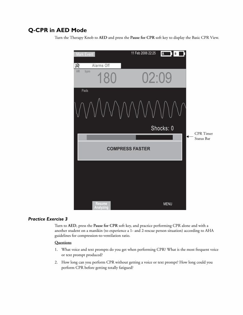
Q-CPR in AED ModeTurn the Therapy Knob to AED and press the Pause for CPR soft key to display the Basic CPR View.
Practice Exercise 3Turn to AED, press the Pause for CPR soft key, and practice performing CPR alone and with a another student on a manikin (to experience a 1- and 2-rescue person situation) according to AHA guidelines for compression-to-ventilation ratio.
Questions
1. What voice and text prompts do you get when performing CPR? What is the most frequent voice or text prompt produced?
2. How long can you perform CPR without getting a voice or text prompt? How long could you perform CPR before getting totally fatigued?
CPR Timer Status Bar
11 Feb 2006 22:25
Alarms OffHR
180 02:09
MENU
bpm
Mark Event
Shocks: 0
Pads
ResumeAnalyzing
COMPRESS FASTER

Lesson Presentation 5 Q-CPR® with CPR meter
Notes:
________________________________________________________________
________________________________________________________________
________________________________________________________________
________________________________________________________________
________________________________________________________________
________________________________________________________________
CPR Feedback Volume AdjustmentTo mute the CPR feedback voice prompts (once you start CPR):
1. Press Menu Select.
2. Select Mute CPR Voice and press Menu Select.
To resume voice prompts set at the previously selected volume:
1. Press Menu Select.
2. Select Resume CPR Voice and press Menu Select.
To adjust the volume of CPR feedback voice prompts:
1. Press the Menu Select button.
2. Select Volume and press Menu Select.
3. Select Voice and press Menu Select.
4. Select the desired volume level and press Menu Select.
51

Review 5 Q-CPR® with CPR meter
ReviewPlease answer the following questions related to Q-CPR.
1. Q-CPR can be used on patients 8 years and older. T or F
2. The multifunction pads should be placed in an anterior/posterior position to measure ventilation activity. T or F
3. The CPR meter can indicate whether you are doing good compressions, what your compression depth is, and what your compression rate is. T or F
4. In Manual Defib Mode, good compression depth is indicated by the downward “peak” of the waveform appearing between the horizontal lines representing the target zone. T or F
5. The ventilation detection icon indicates ventilation has been detected but not the actual filling of both lungs. T or F
6. Only AED Mode provides voice and text prompts associated with compression and ventilation activity. T or F
52

6
User Training Workbook
6Q-CPR® with CompressionSensor
Lesson IntroductionThis lesson describes how to set-up and use the Q-CPR® option (with Compression Sensor) available on the HeartStart MRx.
Note: Q-CPR® is a trademark of Laerdal Medical.
ObjectivesUpon completion of this lesson, you should be able to:
1. Identify intended use and preparation for use related to Q-CPR.
2. Identify characteristics related to Q-CPR in Manual Defib and AED Modes.
Notes:
________________________________________________________________
________________________________________________________________
________________________________________________________________
________________________________________________________________
________________________________________________________________
53

Lesson Presentation 6 Q-CPR® with Compression Sensor
Lesson Presentation
OverviewQ-CPR:
• Offers measurement and corrective feedback on:
– compression rate, depth, and duration time,
– ventilation rate, volume, and flow rate (inflation time)
– CPR inactivity
• Measures compressions through a Compression Sensor and ventilations through multifunction defib electrode pads
• Is used with only the HeartStart MRx
• Is contraindicated:
– on neonatal and pediatric patients (under 8 years of age or weighing less than 25 kg)
– when CPR is contraindicated
– in a moving environment
– with any other CPR compression devices (aside from the Q-CPR Compression Sensor)
• Events related to Q-CPR are not stored in the HeartStart MRx Event Summary.
Notes:
________________________________________________________________
________________________________________________________________
________________________________________________________________
________________________________________________________________
________________________________________________________________
54

Lesson Presentation 6 Q-CPR® with Compression Sensor
Q-CPR Preparation
Follow the steps below to prepare for Q-CPR use.
1. Connect the Pads/CPR cable to the MRx, aligning the white pointer on the cable with the white arrow on the green Therapy port, inserting the cable into the port, and pushing until you hear it click into place. Compression Sensor to the Pads/CPR Cable
2. Connect the Compression Sensor to the Pads/CPR cable, aligning the key marker on the Compression Sensor cable with the key marker on the receptacle end of the Pads/CPR cable, and pushing until you hear it click into place.
3. Attach the Compression Sensor Adhesive Pad to the Compression Sensor, peeling the white liner from the bottom of the Compression Sensor Adhesive Pad, aligning the Sensor Adhesive Pad with the yellow area of the sensor, and pressing into place.
Note: Complete steps 1-3 before a rescue or resuscitation event to save time on set-up.
4. Prepare the patient’s chest and apply the multifunction electrode pads to the patient as directed on the pads package, using the anterior-anterior placement.
5. Connect the pads to the Pads/CPR cable.
6. Place the Compression Sensor on the lower half of the patient’s sternum, which is at the normal CPR hand location.
Notes:
________________________________________________________________
________________________________________________________________
________________________________________________________________
________________________________________________________________
________________________________________________________________
55

Lesson Presentation 6 Q-CPR® with Compression Sensor
Practice Exercise 1Make all cable attachments and then detach a cable to see what inop is produced. Loosen a multifunction pad to see what inop is produced.
Notes:
________________________________________________________________
________________________________________________________________
________________________________________________________________
________________________________________________________________
________________________________________________________________
56
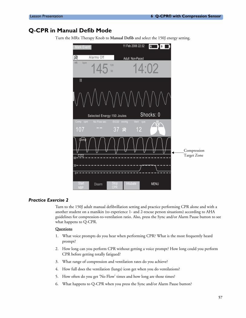
Lesson Presentation 6 Q-CPR® with Compression Sensor
Q-CPR in Manual Defib ModeTurn the MRx Therapy Knob to Manual Defib and select the 150J energy setting.
Practice Exercise 2Turn to the 150J adult manual defibrillation setting and practice performing CPR alone and with a another student on a manikin (to experience 1- and 2-rescue person situations) according to AHA guidelines for compression-to-ventilation ratio. Also, press the Sync and/or Alarm Pause button to see what happens to Q-CPR.
Questions
1. What voice prompts do you hear when performing CPR? What is the most frequently heard prompt?
2. How long can you perform CPR without getting a voice prompt? How long could you perform CPR before getting totally fatigued?
3. What range of compression and ventilation rates do you achieve?
4. How full does the ventilation (lungs) icon get when you do ventilations?
5. How often do you get ‘No Flow’ times and how long are those times?
6. What happens to Q-CPR when you press the Sync and/or Alarm Pause button?
CompressionTarget Zone
11 Feb 2006 22:32
Adult Non- PacedAlarms OffHRHR
145 14:02120120
5050
StartNBP
Disarm MENUStopCPR
Intubate
bpm
Mark Event
107cpm
CO2
12Vent rpm
Selected Energy:150 JoulesCompComp
Comp
Shocks: 0No Flow sec
II
EtC02 mmHg
37
60
30
0
57

Lesson Presentation 6 Q-CPR® with Compression Sensor
Notes:
________________________________________________________________
________________________________________________________________
________________________________________________________________
________________________________________________________________
________________________________________________________________
________________________________________________________________
________________________________________________________________
________________________________________________________________
________________________________________________________________
________________________________________________________________
58
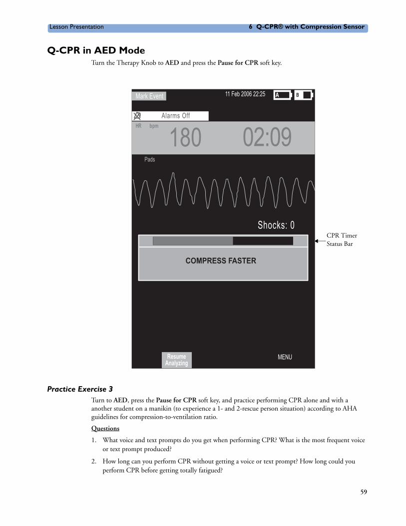
Lesson Presentation 6 Q-CPR® with Compression Sensor
Q-CPR in AED ModeTurn the Therapy Knob to AED and press the Pause for CPR soft key.
Practice Exercise 3Turn to AED, press the Pause for CPR soft key, and practice performing CPR alone and with a another student on a manikin (to experience a 1- and 2-rescue person situation) according to AHA guidelines for compression-to-ventilation ratio.
Questions
1. What voice and text prompts do you get when performing CPR? What is the most frequent voice or text prompt produced?
2. How long can you perform CPR without getting a voice or text prompt? How long could you perform CPR before getting totally fatigued?
CPR Timer Status Bar
11 Feb 2006 22:25
Alarms OffHR
180 02:09
MENU
bpm
Mark Event
Shocks: 0
Pads
ResumeAnalyzing
COMPRESS FASTER
59

Lesson Presentation 6 Q-CPR® with Compression Sensor
Notes:
________________________________________________________________
________________________________________________________________
________________________________________________________________
________________________________________________________________
________________________________________________________________
________________________________________________________________
CPR Feedback Volume AdjustmentTo mute the CPR feedback voice prompts (once you start CPR):
1. Press Menu Select.
2. Select Mute CPR Voice and press Menu Select.
To resume voice prompts set at the previously selected volume:
1. Press Menu Select.
2. Select Resume CPR Voice and press Menu Select.
To adjust the volume of CPR feedback voice prompts:
1. Press the Menu Select button.
2. Select Volume and press Menu Select.
3. Select Voice and press Menu Select.
4. Select the desired volume level and press Menu Select.
60

Review 6 Q-CPR® with Compression Sensor
ReviewPlease answer the following questions related to Q-CPR.
1. Q-CPR can be used on patients 8 years and older. T or F
2. The multifunction pads should be placed in an anterior/posterior position to ensure the ventilation algorithm interprets ventilations properly. T or F
3. The compression sensor should be positioned on the upper half of the patient’s sternum to perform compressions. T or F
4. In Manual Defib Mode, good compression depth is indicated by the downward “peak” of the waveform appearing between the horizontal lines representing the target zone. T or F
5. The ventilation volume icon indicates ventilation has been detected but not the actual filling of both lungs. T or F
6. Only AED Mode provides voice and text prompts associated with compression and ventilation activity. T or F
61


7
User Training Workbook
7Noninvasive Pacing
Lesson IntroductionThis lesson describes the noninvasive transcutaneous pacing option available with the HeartStart MRx and how to perform pacing.
ObjectivesUpon completion of this lesson, you should be able to:
1. Identify pertinent information in Pacing View.
2. Prepare a patient for pacing.
3. Perform demand or fixed mode pacing.
Notes:
________________________________________________________________
________________________________________________________________
________________________________________________________________
________________________________________________________________
________________________________________________________________
63
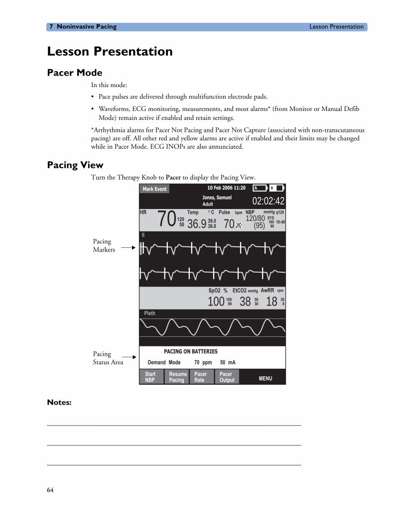
7 Noninvasive Pacing Lesson Presentation
Lesson Presentation
Pacer ModeIn this mode:
• Pace pulses are delivered through multifunction electrode pads.
• Waveforms, ECG monitoring, measurements, and most alarms* (from Monitor or Manual Defib Mode) remain active if enabled and retain settings.
*Arrhythmia alarms for Pacer Not Pacing and Pacer Not Capture (associated with non-transcutaneous pacing) are off. All other red and yellow alarms are active if enabled and their limits may be changed while in Pacer Mode. ECG INOPs are also annunciated.
Pacing ViewTurn the Therapy Knob to Pacer to display the Pacing View.
Notes:
________________________________________________________________
________________________________________________________________
________________________________________________________________
Mark Event 10 Feb 2006 11:20
Jones, SamuelAdult 02:02:42
36.9 70 120/80(95)
Pulse NBP mmHg q120
10:40
bpm CTempSYS160
90
II
HR 7012050 39.0
36.0
SpO2 % EtCO2
100AwRRmmHg rpm
Pleth
MENU
10090 38 50
30 18 308
StartNBP
ResumePacing
PacerRate
PacerOutput
PACING ON BATTERIES
Demand Mode 70 ppm 50 mA
Pacing Markers
Pacing Status Area
64

Lesson Presentation 7 Noninvasive Pacing
Demand vs. Fixed ModeDemand mode
• Pace pulses are delivered when the patient’s heart rate is lower than the selected pacing rate.
• This mode uses monitoring electrodes AND pads for pacing.
• Demand mode is the suggested pacing mode.
Fixed mode
• Pace pulses are delivered at a selected rate.
• Use when motion artifact or ECG noise makes R-wave detection unreliable or when monitoring electrodes are not available.
Notes:
________________________________________________________________
________________________________________________________________
________________________________________________________________
________________________________________________________________
________________________________________________________________
65

7 Noninvasive Pacing Lesson Presentation
PreparationFollow the steps below to prepare for pacing.
1. Prepare the patient’s chest. Wipe moisture away and, if necessary, clip or shave excessive chest hair.
2. Apply multifunction electrode pads to the patient as directed on the pads packaging or according to your organization’s protocol.
3. If not pre-connected, connect the pads cable to green Therapy port on the MRx.
4. Connect the pads connector to the pads cable.
5. If pacing in demand mode, apply monitoring electrodes and connect the ECG cable to the ECG port on the MRx.
Notes:
________________________________________________________________
________________________________________________________________
________________________________________________________________
________________________________________________________________
________________________________________________________________
66

Lesson Presentation 7 Noninvasive Pacing
Demand Mode PacingTo pace in demand mode:
1. Turn the Therapy Knob to the Pacer position.
2. Press the Lead Select button to select the best lead with an easily detectable R-wave.
3. Verify white R-wave markers appear above or on the ECG waveform, with a single marker for each R-wave. If no R-wave markers appear or coincide with the R-wave, select another lead or increase wave size.
4. Press the [Pacer Rate] soft key and use the Navigation and Menu Select buttons to select the desired number of pace pulses per minute.
5. If needed, adjust the initial pacer output. Press [Pacer Output] and use the Navigation and Menu Select buttons to select the desired output.
6. Press [Start Pacing].
7. Verify white pacing markers appear above or on the ECG waveform.
8. Press [Pacer Output]. Then use the Navigation and Menu Select buttons to adjust the output to the lowest level that still maintains capture.
9. Verify the presence of a peripheral pulse.
10. Press [Pause Pacing] to stop pacing. Press [Resume Pacing] to resume delivery, as appropriate.
Note: You may also stop pacing by turning the Therapy Knob from Pacer to another position.
Practice Exercise 1Attach pads and electrodes to the MRx and a simulator, set the simulator to bradycardia, and complete the demand mode pacing steps.
Questions
1. What display changes do you see when completing each step (i.e., turn on pacing, set pacing status, adjust pacer rate and output, and stop pacing)?
2. How do you know when pace pulses are being delivered?
Notes:
________________________________________________________________
________________________________________________________________
________________________________________________________________
________________________________________________________________
________________________________________________________________
67

7 Noninvasive Pacing Lesson Presentation
Fixed Mode PacingTo pace in fixed mode:
1. Turn the Therapy Knob to Pacer.
2. Change the pacer mode to Fixed.
3. Press the Lead Select button to select the desired lead.
Note: The remaining steps are similar to demand mode pacing.
4. Press [Pacer Rate] and use the Navigation and Menu Select buttons to select the desired number of pace pulses per minute.
5. If needed, adjust the initial pacer output by pressing [Pacer Output] and using the Navigation and Menu Select buttons to select the desired output.
6. Press [Start Pacing].
7. Verify the presence of a peripheral pulse.
8. Press [Pacer Output] and use the Navigation and Menu Select buttons to adjust the output, as needed.
9. Press [Pause Pacing] to stop pacing.
Practice Exercise 2Attach pads and electrodes to the MRx and a simulator, set the simulator to bradycardia, and complete the fixed mode pacing steps.
Questions
1. What display changes do you see when completing each step (i.e., turn on pacing, set pacing status, adjust pacer rate and output, and stop pacing)?
2. How do you know when pace pulses are being delivered?
Notes:
________________________________________________________________
________________________________________________________________
________________________________________________________________
________________________________________________________________
________________________________________________________________
68

Lesson Presentation 7 Noninvasive Pacing
Defibrillating During PacingTo defibrillate, turn the Therapy Knob to Manual Defib or AED. Note that:
• Pacing stops in either Manual Defib or AED Mode.
• Pacing settings selected prior to defibrillation are retained once pacing recommences.
Notes:
________________________________________________________________
________________________________________________________________
________________________________________________________________
________________________________________________________________
69

7 Noninvasive Pacing Review
ReviewPlease answer the following questions related to pacing.
1. Which of the following statement(s) are TRUE related to pacing with the MRx?
a. The device requires a 3-, 5- or 10-Lead ECG cable and monitoring electrodes during demand mode pacing.
b. The device always delivers pace pulses in demand mode.
c. The Pacing status area indicates pacing mode, status, rate, and output.
d. If you exit Pacing Mode to defibrillate and then return to pacing, the settings from the previous pacing session must be re-entered.
2. Which ONE of the following steps should be performed before pacing is initiated in demand mode?
a. Verify that a white pacing marker appears in front of each QRS complex.
b. Verify that white R-wave markers appear above or on the ECG waveform.
c. Increase pacer output until capture occurs.
d. Decrease pacer output to the lowest level that still maintains capture.
70

8
User Training Workbook
8Pulse Oximetry Monitoring
Lesson IntroductionThis lesson describes how to use the HeartStart MRx to monitor Pulse Oximetry (SpO2).
ObjectivesUpon completion of this lesson, you should be able to:
1. Monitor SpO2.
2. Set SpO2 and pulse rate alarms.
Notes:
________________________________________________________________
________________________________________________________________
________________________________________________________________
________________________________________________________________
________________________________________________________________
71

8 Pulse Oximetry Monitoring Lesson Presentation
Lesson Presentation
Monitoring SpO2To monitor SpO2:
1. Connect the appropriate sensor cable to the MRx.
2. Apply the sensor to the patient. If a finger sensor is used, the cable should come down the back of the hand.
3. Turn the Therapy Knob to Monitor.
Notes:
________________________________________________________________
________________________________________________________________
________________________________________________________________
________________________________________________________________
________________________________________________________________
72

Lesson Presentation 8 Pulse Oximetry Monitoring
Setting SpO2 Alarms
Changing Alarm LimitsTo change the SpO2 alarm limits:
1. Press the Menu Select button.
2. Using the Navigation buttons, select Measurements/Alarms and press Menu Select.
3. Select SpO2 and press Menu Select.
4. Select SpO2 Limits and press Menu Select.
5. Using the Navigation buttons, select the new high limit value and press Menu Select.
6. Select the new low limit value and press Menu Select.
Enabling/Disabling AlarmsTo enable the SpO2 alarms:
1. Press the Menu Select button.
2. Select Measurements/Alarms and press Menu Select.
3. Select SpO2 and press Menu Select.
4. Select Alarms On/Off and press Menu Select.
Practice Exercise 1Change the SpO2 limits, and enable/disable and respond to related alarms.
Questions
What happens when you change a limit? Disable an alarm? Respond to an alarm?
Notes:
________________________________________________________________
________________________________________________________________
________________________________________________________________
________________________________________________________________
________________________________________________________________
73

8 Pulse Oximetry Monitoring Lesson Presentation
Setting Pulse Rate Alarms
Changing Pulse Rate Alarm LimitsTo change pulse rate alarm limits:
1. Press the Menu Select button.
2. Using the Navigation buttons, select Measurements/Alarms and press Menu Select.
3. Select Pulse and press Menu Select.
4. Select Pulse Limits and press Menu Select.
5. Using the Navigation buttons, select the new high limit value and press Menu Select.
6. Select the new low limit value and press Menu Select.
Enabling/Disabling Pulse Rate AlarmsTo enable pulse rate alarms:
1. Press the Menu Select button.
2. Select Measurements/Alarms and press Menu Select.
3. Select Pulse and press Menu Select.
4. Select Alarms On/Off and press Menu Select.
Practice Exercise 2Change the pulse rate limits, and enable/disable and respond to related alarms.
Question
What happens when you change a limit? Disable an alarm? Respond to an alarm?
Notes:
________________________________________________________________
________________________________________________________________
________________________________________________________________
________________________________________________________________
________________________________________________________________
74

Lesson Presentation 8 Pulse Oximetry Monitoring
Disabling SpO2 MonitoringTo disable SpO2 monitoring:
• Disconnect the sensor cable from the SpO2 port. The message SpO2 Unplugged. Turn off SpO2? appears. Select Yes and press Menu Select.
• Should the sensor cable be disconnected accidentally, select No and press Menu Select. Then, secure the connection to re-enable the function.
Notes:
________________________________________________________________
________________________________________________________________
________________________________________________________________
________________________________________________________________
75

8 Pulse Oximetry Monitoring Review
ReviewAnswer the following questions related to SpO2 monitoring.
1. You can monitor SpO2 in all MRx modes (Monitor, Manual Defib, AED or Pacer). T or F
2. The pleth wave is auto scaled to grid lines when the signal quality is poor. T or F
3. SpO2 alarms are off unless turned on during use while pulse rate alarms are on unless turned off during use. T or F
4. How many seconds are SpO2 INOP messages suppressed during an NBP measurement?
a. 15
b. 30
c. 45
d. 60
76

9
User Training Workbook
9Noninvasive Blood PressureMonitoring
Lesson IntroductionThis lesson describes how to monitor noninvasive blood pressure (NBP) with the HeartStart MRx.
ObjectivesUpon completion of this lesson, you should be able to:
1. Monitor NBP.
2. Set NBP alarms.
Notes:
________________________________________________________________
________________________________________________________________
________________________________________________________________
________________________________________________________________
________________________________________________________________
77

9 Noninvasive Blood Pressure Monitoring Lesson Presentation
Lesson Presentation
Preparing to Measure NBPTo prepare to measure NBP:
1. Select the appropriately sized cuff.
2. Attach the cuff to the NBP tubing.
3. Insert the NBP tubing into the NBP port on the MRx.
4. Apply the blood pressure cuff to the patient’s arm.
5. Place the limb used for taking the measurement at the same level as the patient’s heart.
Notes:
________________________________________________________________
________________________________________________________________
________________________________________________________________
________________________________________________________________
________________________________________________________________
78

Lesson Presentation 9 Noninvasive Blood Pressure Monitoring
Measuring NBP To measure NBP:
1. Press the [Start NBP] soft key.
2. Press the [Stop NBP] soft key to stop a reading.
Changing the NBP ScheduleTo change the NBP schedule and/or the interval of automatic measurements:
1. Press the Menu Select button.
2. Using the Navigation buttons, select Measurements/Alarms and press Menu Select.
3. Select NBP and press Menu Select.
4. Select NBP Schedule and press Menu Select.
5. Using the Navigation buttons, select the desired interval and press Menu Select.
Practice Exercise 1Complete manual and automatic NBP measurements, including changing the NBP schedule.
Questions
1. What displays when you start a measurement? Stop a measurement?
2. How does the display differ between a manual and automatic measurement?
Notes:
________________________________________________________________
________________________________________________________________
________________________________________________________________
________________________________________________________________
________________________________________________________________
79

9 Noninvasive Blood Pressure Monitoring Lesson Presentation
Alarms
Changing NBP AlarmsTo change the NBP alarm source and/or limits:
1. Press the Menu Select button.
2. Using the Navigation buttons, select Measurements/Alarms and press Menu Select.
3. Select NBP and press Menu Select.
4. Select NBP Limits and press Menu Select.
5. Select the desired source for the alarm and press Menu Select.
6. Using the Navigation buttons, increase or decrease the high limit value and press Menu Select.
7. Set the new low limit value and press Menu Select.
Enabling/Disabling NBP AlarmsTo enable/disable NBP alarms:
1. Press the Menu Select button.
2. Using the Navigation buttons, select Measurements/Alarms and press Menu Select.
3. Select NBP and press Menu Select.
4. Select Alarms On/Off and press Menu Select.
Practice Exercise 2Change the alarm limits, and enable/disable and respond to related alarms.
Questions
1. What happens when you change a limit? Disable an alarm? Respond to an alarm?
Notes:
________________________________________________________________
________________________________________________________________
________________________________________________________________
________________________________________________________________
________________________________________________________________
80

Review 9 Noninvasive Blood Pressure Monitoring
ReviewAnswer the following questions related to monitoring NBP.
1. Which of the following items can display when monitoring NBP?
a. Systolic and diastolic pressure
b. Alarm limits
c. Automatic measurement schedule
d. Time stamp
2. You can take manual measurements during an automatic measurement schedule. T or F
3. NBP alarms are “on” unless disabled. T or F
81


10
User Training Workbook
10Carbon Dioxide Monitoring
Lesson IntroductionThis lesson describes how to monitor carbon dioxide (CO2) and measure end-tidal carbon dioxide (EtCO2) and Airway Respiration Rate (AwRR) with the HeartStart MRx using the Microstream® (sidestream) method.
Note: Microstream® is a trademark of Oridion Medical Ltd.
ObjectivesUpon completion of this lesson, you should be able to:
1. Monitor CO2.
2. Set EtCO2 and AwRR alarms.
Notes:
________________________________________________________________
________________________________________________________________
________________________________________________________________
________________________________________________________________
________________________________________________________________
83

10 Carbon Dioxide Monitoring Lesson Presentation
Lesson Presentation
Measuring EtCO2To prepare and measure EtCO2:
1. Select the appropriate Microstream accessories based on the type and airway status of the patient.
2. Set up the Microstream accessories.
Using the nasal FilterLine®
a. Attach the FilterLine tubing to the CO2 Inlet port.
b. Position the nasal FilterLine on the patient. If using dual purpose FilterLine tubing, connect the green tubing to the oxygen source.
Note: FilterLine® is a trademark of Oridion Medical Ltd.
Using the FilterLine and airway adapter
a. Attach the FilterLine tubing to the CO2 Inlet port.
b. Connect the wide end of the airway adapter to the endotracheal tube.
c. Connect the narrow end of the airway adapter to the ventilator tubing or manual resuscitator.
3. A measurement is automatically turned on when the FilterLine is connected to the CO2 Inlet port.
Note: The Outlet port is used for removing anesthetic gases from MRx.
Notes:
________________________________________________________________
________________________________________________________________
________________________________________________________________
________________________________________________________________
________________________________________________________________
84
Lesson Presentation 10 Carbon Dioxide Monitoring
Setting Up the EtCO2 and AwRR Alarms
Changing EtCO2 Alarm Limits
To change the EtCO2 alarm limits:
1. Press the Menu Select button.
2. Using the Navigation buttons, select Measurements/Alarms and press Menu Select.
3. Select EtCO2 and press Menu Select.
4. Select EtCO2 Limits and press Menu Select.
5. Using the Navigation buttons, increase or decrease the high limit value and press Menu Select.
6. Set the new low limit value and press Menu Select.
Enabling/Disabling EtCO2 Alarms
To enable or disable the EtCO2 alarms:
1. Press Menu Select. Using the Navigation buttons, select Measurements/Alarms and press Menu Select.
2. Select EtCO2 and press Menu Select.
3. Select Alarms On/Off and press Menu Select.
Changing AwRR Alarm LimitsTo change the AwRR alarm limits:
1. Press Menu Select.
2. Using the Navigation buttons, select Measurements/Alarms and press Menu Select.
3. Select AwRR and press Menu Select.
4. Select AwRR Limits and press Menu Select.
5. Using the Navigation buttons, increase or decrease the high limit value and press Menu Select.
6. Set the new low limit value and press Menu Select.
Changing Apnea Time Alarm LimitTo change the Apnea Time alarm limit:
1. Press Menu Select.
2. Using the Navigation buttons, select Measurements/Alarms and press Menu Select.
3. Select AwRR and press Menu Select.
4. Select Apnea Time and press Menu Select.
5. Using the Navigation buttons, increase or decrease the limit and press Menu Select.
85

10 Carbon Dioxide Monitoring Lesson Presentation
Enabling/Disabling AwRR AlarmsTo enable the AwRR alarms:
1. Press Menu Select.
2. Using the Navigation buttons, select Measurements/Alarms and press Menu Select.
3. Select AwRR and press Menu Select.
4. Select Alarms On/Off and press Menu Select.
Practice Exercise 1Change EtCO2, AwRR, and Apnea Time limits, and enable/disable and respond to related alarms.
Questions
1. What happens when you change a limit? Disable an alarm? Respond to an alarm?
Notes:
________________________________________________________________
________________________________________________________________
________________________________________________________________
________________________________________________________________
________________________________________________________________
________________________________________________________________
86

Lesson Presentation 10 Carbon Dioxide Monitoring
Disabling EtCO2 MonitoringTo disable EtCO2 monitoring:
• Disconnect the FilterLine from the CO2 inlet port. The message CO2 Unplugged - Turn Off EtCO2? appears. Select Yes and press Menu Select.
• Should the FilterLine be disconnected accidentally, select No in response to the message and press Menu Select. Then, secure the connection to re-enable the function.
Notes:
________________________________________________________________
________________________________________________________________
________________________________________________________________
________________________________________________________________
87

10 Carbon Dioxide Monitoring Review
ReviewAnswer the following questions related to monitoring CO2.
1. EtCO2 values may be significantly low if a patient is breathing through their mouth when using a nasal FilterLine. T or F
2. The CO2 waveform only displays in Wave Sector 3. T or F
3. FilterLine or exhaust tubing blockage can generate an apnea alarm. T or F
4. AwRR alarms are disabled unless turned enabled during use. T or F
88

11
User Training Workbook
11Invasive Pressures Monitoring
Lesson IntroductionThis lesson describes how to monitor invasive pressures using the HeartStart MRx.
ObjectivesUpon completion of this lesson, you should be able to:
1. Set up a pressure measurement.
2. Select a pressure to monitor.
3. Zero the pressure transducer.
4. Set pressure alarms and view related settings.
5. Identify how pulse works with the Invasive Pressures option.
89

11 Invasive Pressures Monitoring Lesson Presentation
Lesson Presentation
Overview• Two channels of real-time continuous invasive pressure measurements and waveforms are available
in Monitor, Manual Defib and Pacer Modes.
• Systolic, diastolic and mean pressure values display for pulsatile pressure signals and mean value for non-pulsatile pressure signals.
Pressure Measurement Set-upTo set up medical equipment to display a pressure measurement on the MRx:
1. Turn the HeartStart MRx to Monitor.
2. Connect the pressure cable to the MRx.
3. Connect the pressure cable to the transducer.
4. Prepare the flush solution.
5. Flush the system to expel air from the tubing. Make sure the stopcocks and transducer are also free of air bubbles.
6. Connect the pressure line to the patient catheter.
7. If you are using an infusion pressure cuff with the pressure line, attach the pressure cuff to the fluid to be infused. Inflate it according to your hospital’s standard procedure and then begin the infusion. Position the transducer so that it is level with the heart, approximately at the level of the midaxillary line.
Notes:
________________________________________________________________
________________________________________________________________
________________________________________________________________
________________________________________________________________
________________________________________________________________
90
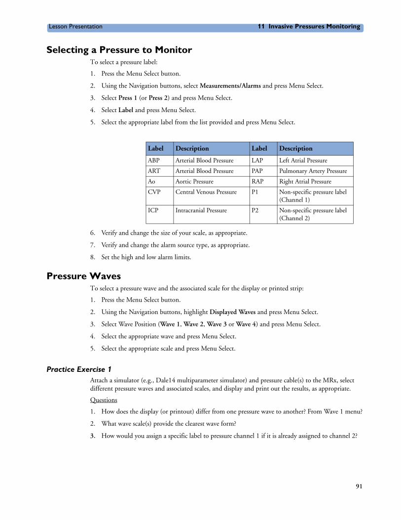
Lesson Presentation 11 Invasive Pressures Monitoring
Selecting a Pressure to MonitorTo select a pressure label:
1. Press the Menu Select button.
2. Using the Navigation buttons, select Measurements/Alarms and press Menu Select.
3. Select Press 1 (or Press 2) and press Menu Select.
4. Select Label and press Menu Select.
5. Select the appropriate label from the list provided and press Menu Select.
6. Verify and change the size of your scale, as appropriate.
7. Verify and change the alarm source type, as appropriate.
8. Set the high and low alarm limits.
Pressure WavesTo select a pressure wave and the associated scale for the display or printed strip:
1. Press the Menu Select button.
2. Using the Navigation buttons, highlight Displayed Waves and press Menu Select.
3. Select Wave Position (Wave 1, Wave 2, Wave 3 or Wave 4) and press Menu Select.
4. Select the appropriate wave and press Menu Select.
5. Select the appropriate scale and press Menu Select.
Practice Exercise 1Attach a simulator (e.g., Dale14 multiparameter simulator) and pressure cable(s) to the MRx, select different pressure waves and associated scales, and display and print out the results, as appropriate.
Questions
1. How does the display (or printout) differ from one pressure wave to another? From Wave 1 menu?
2. What wave scale(s) provide the clearest wave form?
3. How would you assign a specific label to pressure channel 1 if it is already assigned to channel 2?
Label Description Label Description
ABP Arterial Blood Pressure LAP Left Atrial Pressure
ART Arterial Blood Pressure PAP Pulmonary Artery Pressure
Ao Aortic Pressure RAP Right Atrial Pressure
CVP Central Venous Pressure P1 Non-specific pressure label (Channel 1)
ICP Intracranial Pressure P2 Non-specific pressure label (Channel 2)
91

11 Invasive Pressures Monitoring Lesson Presentation
Notes:
________________________________________________________________
________________________________________________________________
________________________________________________________________
________________________________________________________________
________________________________________________________________
92
Lesson Presentation 11 Invasive Pressures Monitoring
Zeroing the Pressure Transducer
Zeroing Using the Menu Select ButtonTo zero the transducer using the Menu Select button:
1. Place the transducer at the appropriate level for the measurement site.
2. Close the transducer stopcock to the patient and vent the transducer to atmospheric pressure.
3. Press the Menu Select button.
4. Using the Navigation buttons, select Measurements/Alarms and press Menu Select.
5. Select the pressure label you wish to zero.
6. Press Zero and press Menu Select. Zeroing begins.
Zeroing in Monitor ModeTo zero the transducer in Monitor Mode:
1. Place the transducer at the appropriate level for the measurement site.
2. Close the transducer stopcock to the patient and vent the transducer to atmospheric pressure.
3. Press the soft key under the [Zero Pressure] label.
4. Using the Navigation buttons, select the pressure(s) you wish to zero from the Zero menu and press Menu Select. Zeroing begins.
Last ZeroTo view dates and times for a channel’s last zero:
1. Press the Menu Select button.
2. Using the Navigation buttons, select Measurements/Alarms and press Menu Select.
3. Select the pressure label (channel: label) you want and press Menu Select.
4. The last zero dates and times are displayed.
Notes:
________________________________________________________________
________________________________________________________________
________________________________________________________________
________________________________________________________________
93
11 Invasive Pressures Monitoring Lesson Presentation
Alarms
Enabling/Disabling AlarmsTo enable/disable alarms:
1. Press the Menu Select button.
2. Using the Navigation buttons, select Measurements/Alarms and press Menu Select.
3. Select the pressure label (channel: label) you wish to modify alarm status on and press Menu Select.
4. Select Alarms On (or Alarms Off ) and press Menu Select.
Viewing/Changing/Setting Source for AlarmsTo view or change alarm settings for a given pressure label:
1. Press the Menu Select button.
2. Using the Navigation buttons, select Measurements/Alarms and press Menu Select.
3. Select the pressure label (channel: label) you wish to view/modify alarms on and press Menu Select.
4. Select pressure label Limits and press Menu Select.
5. If the pressure label is pulsatile, select the desired source of the alarm (Systolic, Diastolic or Mean) and press Menu Select.
6. Using the Navigation buttons, increase or decrease the high limit and press Menu Select.
7. Set the new low limit and press Menu Select.
Practice Exercise 2Change invasive pressure alarm limits, and enable/disable and respond to related alarms.
Questions
1. What happens when you change a limit? Disable an alarm? Respond to an alarm?
Notes:
________________________________________________________________
________________________________________________________________
________________________________________________________________
________________________________________________________________
94
Lesson Presentation 11 Invasive Pressures Monitoring
Pulse
Changing Pulse SourceTo change pulse source for the current incident:
1. Press the Menu Select button.
2. Using the Navigation buttons, select Measurements/Alarms and press Menu Select.
3. Select Pulse and press Menu Select.
4. Select Pulse Source and press Menu Select. Pick a source with an arterial or pulmonary waveform.
5. Using the Navigation buttons, highlight the pulse source desired and press Menu Select.
Enabling/Disabling the Pulse AlarmTo enable/disable the pulse alarm:
1. Press the Menu Select button.
2. Using the Navigation buttons, select Measurements/Alarms and press Menu Select.
3. Select Pulse and press Menu Select.
4. Select Alarms On/Off and press Menu Select.
Changing Pulse Alarm LimitsTo change pulse alarm limits:
1. Press the Menu Select button.
2. Using the Navigation buttons, select Measurements/Alarms and press Menu Select.
3. Select Pulse and press Menu Select.
4. Select Pulse Limits and press Menu Select.
5. Using the Navigation buttons, select the new high limit value and press Menu Select.
6. Select the new low limit and press Menu Select.
Practice Exercise 3Change pulse alarm limits, and enable/disable and respond to related alarms.
Questions
1. What happens when you change a limit? Disable an alarm? Respond to an alarm?
95

11 Invasive Pressures Monitoring Lesson Presentation
Notes:
________________________________________________________________
________________________________________________________________
________________________________________________________________
________________________________________________________________
96
Review 11 Invasive Pressures Monitoring
ReviewAnswer the following questions related to monitoring invasive pressures.
1. You must flush the tubing system to remove air bubbles to prevent potential incorrect readings. T or F
2. Which of the following statement(s) are TRUE regarding pressure selection and related wave scale adjustment?
a. When selecting a label, you need to specify its color, alarm source and limits, and scale.
b. Controls for scale and alarm settings automatically appear after selecting a new label.
c. You can not select the same label for both pressure channels.
d. The available pressure wave scale spans from 300 to -20 in mmHg and from 38 to -2.5 in kPa.
3. Which of the following statement(s) are TRUE regarding zeroing a pressure?
a. You must zero a pressure every time you reconnect the transducer cable to the MRx.
b. Before zeroing a pressure, you must vent pressure transducers to atmospheric pressure and close the stopcock to the patient.
c. Invasive pressure alarms are active while the transducer is zeroing.
d. The message Unable to zero message displays if the zeroing process fails.
4. Which of the following statement(s) are TRUE regarding pressure alarms?
a. All invasive pressure alarms cease when their alarm condition no longer exists.
b. The PAPd High message means the pulmonary artery diastolic pressure has exceeded the high alarm limit.
c. If the pressure label is non-pulsatile, you select either Systolic, Diastolic or Mean as the desired alarm source.
d. When CPP and ICP are displayed together, only one of them can have related alarms enabled.
5. If SpO2, as the default pulse source, is not active but the ABP source is, the pulse value displays but it is invalid. T or F
97


12
User Training Workbook
12Temperature Monitoring
Lesson IntroductionThis lesson describes how to monitor temperature using the HeartStart MRx.
ObjectivesUpon completion of this lesson, you should be able to:
1. Select a temperature to monitor.
2. Set temperature alarms and related limits.
Notes:
________________________________________________________________
________________________________________________________________
________________________________________________________________
________________________________________________________________
99
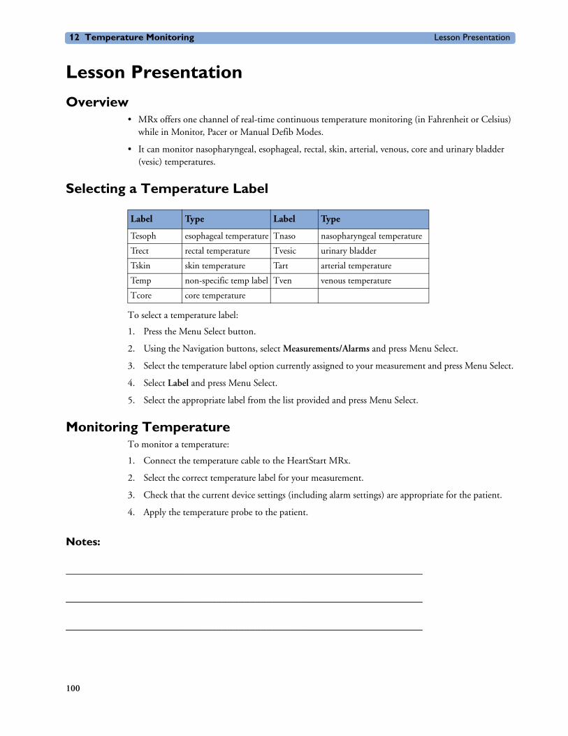
12 Temperature Monitoring Lesson Presentation
Lesson Presentation
Overview• MRx offers one channel of real-time continuous temperature monitoring (in Fahrenheit or Celsius)
while in Monitor, Pacer or Manual Defib Modes.
• It can monitor nasopharyngeal, esophageal, rectal, skin, arterial, venous, core and urinary bladder (vesic) temperatures.
Selecting a Temperature Label
To select a temperature label:
1. Press the Menu Select button.
2. Using the Navigation buttons, select Measurements/Alarms and press Menu Select.
3. Select the temperature label option currently assigned to your measurement and press Menu Select.
4. Select Label and press Menu Select.
5. Select the appropriate label from the list provided and press Menu Select.
Monitoring TemperatureTo monitor a temperature:
1. Connect the temperature cable to the HeartStart MRx.
2. Select the correct temperature label for your measurement.
3. Check that the current device settings (including alarm settings) are appropriate for the patient.
4. Apply the temperature probe to the patient.
Notes:
________________________________________________________________
________________________________________________________________
________________________________________________________________
Label Type Label Type
Tesoph esophageal temperature Tnaso nasopharyngeal temperature
Trect rectal temperature Tvesic urinary bladder
Tskin skin temperature Tart arterial temperature
Temp non-specific temp label Tven venous temperature
Tcore core temperature
100
Lesson Presentation 12 Temperature Monitoring
Setting Temperature Alarms
Changing Alarm LimitsTo change the temperature alarm limits for the current incident:
1. Press the Menu Select button.
2. Using the Navigation buttons, select Measurements/Alarms and press Menu Select.
3. Select the temperature label option currently assigned to your measurement and press Menu Select.
4. Select Temperature Limits and press Menu Select.
5. Using the Navigation buttons, change the high limit and press Menu Select.
6. Using the Navigation buttons, change the low limit and press Menu Select.
Disabling/Enabling AlarmsTo disable/enable temperature alarms:
1. Press the Menu Select button.
2. Using the Navigation buttons, select the Measurements/Alarms menu and press Menu Select.
3. Select the temperature label option currently assigned to your measurement and press Menu Select.
4. Select Alarms Off/Alarms On and press Menu Select.
Disabling Temperature MonitoringTo disable the Temperature monitoring:
• Disconnect the temperature cable from the MRx Temperature port. The message Temp (or the label currently activated) Unplugged. Turn Off Temp (or the label currently activated)? appears. Select Yes and press the Menu Select button.
• Should the temperature cable get disconnected accidentally or if the probe and cable separate, and you want to continue monitoring temperature, select No and press Menu Select. Reconnect the temperature cable to restart the temperature monitoring function.
Practice Exercise 1Change temperature alarm limits, and disable/enable and respond to related alarms.
Questions
1. What happens when you change a limit? Disable an alarm? Respond to an alarm?
101

12 Temperature Monitoring Lesson Presentation
Notes:
________________________________________________________________
________________________________________________________________
________________________________________________________________
102

Review 12 Temperature Monitoring
ReviewAnswer the following questions related to monitoring temperature.
1. When you change a temperature label, you need to activate its related alarm limits. T or F
2. Which of the following statement(s) are TRUE regarding temperature alarms?
a. All temperature alarms cease when their alarm condition no longer exists.
b. The Tesoph Low message means the esophageal temperature has fallen below the low alarm limit.
c. Temperature alarms default to off.
d. Changing the label may change the alarm limits.
103


13
User Training Workbook
1312-Lead ECG Monitoring
Lesson IntroductionThis lesson describes how to use the diagnostic 12-Lead ECG function of the HeartStart MRx.
ObjectivesUpon completion of this lesson, you should be able to:
1. Identify pertinent information in the 12-Lead Preview screen.
2. Perform 12-Lead ECG acquisition.
3. Identify characteristics of the ACI-TIPI and TPI algorithms. (Optional objective)
4. Identify important characteristics of the 12-Lead Report.
Notes:
________________________________________________________________
________________________________________________________________
________________________________________________________________
________________________________________________________________
________________________________________________________________
________________________________________________________________
105
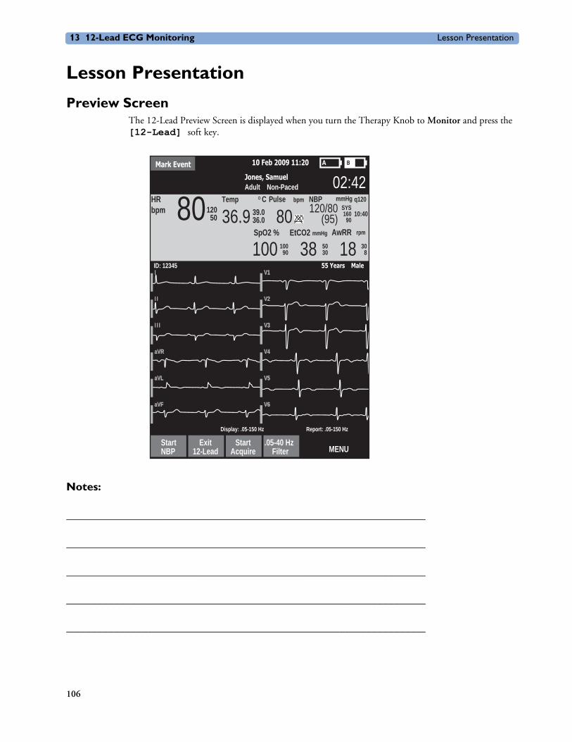
13 12-Lead ECG Monitoring Lesson Presentation
Mark Event 10 Feb 2009 11:20
Jones, SamuelAdult Non-Paced 02:42
36.9 80 120/80(95)
Pulse NBP mmHg q120
10:40
bpm CTempSYS16090
HRbpm 80120
5039.036.0
SpO2 % EtCO2
100AwRRmmHg rpm
10090 38 50
30 18 308
StartNBP
Exit12-Lead
StartAcquire
.05-40 HzFilter MENU
ID: 12345 55 Years MaleV1V1II
V2V2I II I
V3V3I I I I I I
V4V4aVRaVR
V5V5aVLaVL
V6V6aVFaVF
Display: .05-150 Hz Report: .05-150 Hz
Lesson Presentation
Preview ScreenThe 12-Lead Preview Screen is displayed when you turn the Therapy Knob to Monitor and press the [12-Lead] soft key.
Notes:
________________________________________________________________
________________________________________________________________
________________________________________________________________
________________________________________________________________
________________________________________________________________
106

Lesson Presentation 13 12-Lead ECG Monitoring
PreparationTo prepare for ECG acquisition:
1. Connect the 10-Lead cable to the MRx.
2. Prepare the patient’s skin at appropriate electrode sites.
– If necessary, clip hair at the electrode sites (or shave sites if needed).
– Wash sites thoroughly with soap and water.
– Dry the electrode sites briskly to increase capillary blood flow in the tissues and to remove oil and skin cells.
3. Attach the snaps to the electrodes.
4. Apply the electrodes to the patient. (Use the 10-Lead placement illustrated below.)
5. Turn the Therapy Knob to Monitor.
6. Enter the patient’s ID, name, age, and sex. Also, enter chest pain symptoms if the MRx is configured to run the ACI-TIPI and TPI algorithms.
7. Confirm the patient’s pacing status is correct.
Note: With software version F.xx, the paced status is determined by the DXL ECG Algorithm.
107

13 12-Lead ECG Monitoring Lesson Presentation
Notes:
________________________________________________________________
________________________________________________________________
________________________________________________________________
________________________________________________________________
________________________________________________________________
Acquiring the 12-Lead ECGTo acquire a 12-Lead ECG:
1. Press the [12-Lead] soft key.
2. Check the signal quality on each lead and, if necessary, make adjustments.
3. Press the [Start Acquire] soft key.
4. If the patient age and sex haven’t been entered, input this information using the Navigation and Menu Select buttons. If connected to the IntelliVue Network, you enter the patient’s date of birth (instead of age). Also, enter the patient’s chest pain symptoms if your MRx is configured to run the ACI-TIPI and TPI algorithms.
5. Keep the patient still while the message Acquiring 12-Lead is displayed.
6. ECG analysis begins once acquisition is complete.
7. Following analysis, the 12-Lead Report is displayed, printed, and stored internally.
8. Press [New 12-Lead] to acquire another 12-Lead ECG.
9. Press [Exit 12-Lead] to exit the 12-Lead function.
Practice Exercise 1Attach a 10-Lead set to the MRx and a simulator, set the simulator to a normal sinus rhythm (NSR), and complete 12-Lead acquisition.
Questions
What display changes occur when you press the [Start Acquire] soft key? When acquisition is completed? When analysis is completed?
108

Lesson Presentation 13 12-Lead ECG Monitoring
Notes:
________________________________________________________________
________________________________________________________________
________________________________________________________________
________________________________________________________________
________________________________________________________________
Acquiring a 12-lead ECG with ACI-TIPI or ACI-TIPI/TPI AnalysisTo acquire a 12-lead ECG with ACI-TIPI or ACI-TIPI and TPI analysis:
1. Perform steps 1-5 from the previous “Acquiring the 12-Lead ECG” procedure.
2. If the MRx is not configured for TPI analysis, the 12-Lead Report (including the ACI-TIPI predicted probability of acute ischemia percentage) is displayed, printed, and stored internally.
If the MRx is configured for TPI analysis, it performs a TPI screening test to see if the ECG is a candidate for TPI analysis. (Press the [Skip TPI] softkey to bypass TPI analysis.)
– If the ECG is not a candidate, the 12-Lead Report is displayed, printed, and stored internally.
– If the ECG is a candidate, you’re prompted to input more patient information. Continue with Step 3.
3. When required, the MRx displays a list of TPI patient data and related values that must be entered.
Press Menu Select to view possible values for the first highlighted topic.
4. Select and complete all inputs, and press the [Run TPI] softkey.
5. Select any thrombolytic therapy contraindications from a pre-configured list based on speaking with and observing the patient.
To change a contraindication:
1. When the list of contraindications appears on the MRx display, use the navigation arrows to highlight one of the contraindications and press the Menu Select button.
2. Use the Navigation arrows to select a new value for the contraindication and press Menu Select.
3. Use the Navigation arrows to select the next contraindication.
4. Complete steps 1-3 for the remaining contraindications in the list. Navigate to additional page(s) as needed.
5. Press the [Done] softkey to exit contraindications to thrombolytic therapy. The 12-Lead analysis is complete.
6. To acquire another 12-Lead ECG, press [New 12-Lead]. To exit the 12-lead function, press [Exit 12-Lead].
109
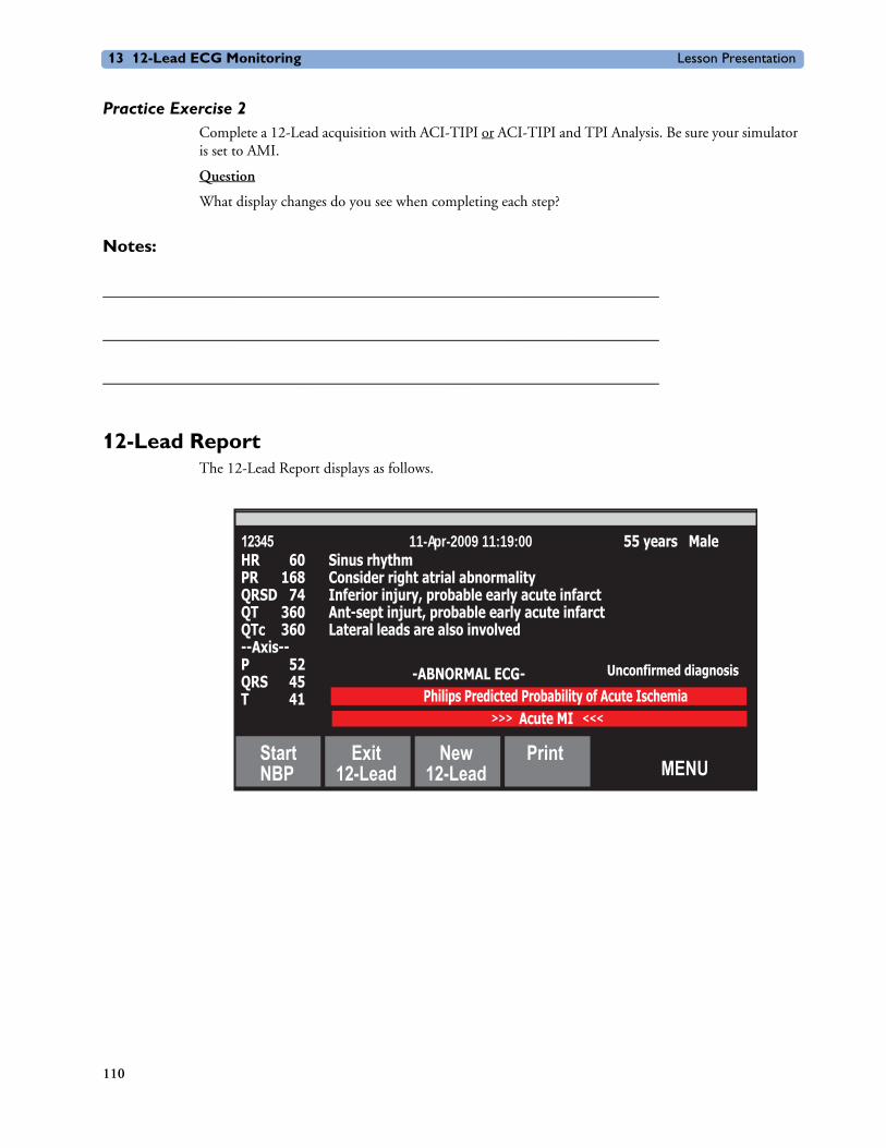
13 12-Lead ECG Monitoring Lesson Presentation
Practice Exercise 2Complete a 12-Lead acquisition with ACI-TIPI or ACI-TIPI and TPI Analysis. Be sure your simulator is set to AMI.
Question
What display changes do you see when completing each step?
Notes:
________________________________________________________________
________________________________________________________________
________________________________________________________________
12-Lead ReportThe 12-Lead Report displays as follows.
StartNBP
Exit12-Lead
New12-Lead
PrintMENU
HR 60PR 168QRSD 74QT 360QTc 360--Axis--P 52QRS 45T 41
12345 11-Apr-2009 11:19:00
-ABNORMAL ECG- Unconfirmed diagnosis
55 years MaleSinus rhythmConsider right atrial abnormalityInferior injury, probable early acute infarctAnt-sept injurt, probable early acute infarctLateral leads are also involved
Acute MI >>> <<<
Philips Predicted Probability of Acute Ischemia
110

Lesson Presentation 13 12-Lead ECG Monitoring
Notes:
________________________________________________________________
________________________________________________________________
________________________________________________________________
________________________________________________________________
________________________________________________________________
Accessing Stored ReportsTo access stored reports to print additional copies, copy them to a data card, or delete them from internal storage:
1. While in 12-Lead Mode, press the Menu Select button.
2. Use the Navigation buttons to select Reports.
3. Use the Navigation buttons to select a report and press Menu Select.
4. Select Print, Copy, or Delete and press Menu Select.
5. Press Exit to close the menu.
Adjusting Wave SizeTo adjust the ECG wave size:
1. While in 12-Lead Mode, press the Menu Select button.
2. Using the Navigation buttons, select ECG Size and press Menu Select.
3. Using the Navigation buttons, select the desired size value and press Menu Select.
Notes:
________________________________________________________________
________________________________________________________________
________________________________________________________________
________________________________________________________________
________________________________________________________________
111

ReviewAnswer the following questions related to 12-Lead ECG.
1. Which of the following statement(s) are FALSE? The 12-Lead Preview screen displays:
a. Patient ID, age, and sex.
b. Waveforms presented at a rate of 15mm/sec. for approximately 2.5 seconds.
c. A dotted line which indicates a lead can’t be derived.
d. SpO2, CO2, and NBP measurements in Parameter Blocks 1 and 2, if configured.
2. Once ECG acquisition is complete, you press the Start Analysis soft key to start ECG analysis.
T or F
3. The MRx acquires how many seconds of ECG data?
a. 5
b. 10
c. 12
d. 15
4. Which one of the following inputs is required by the ACI-TIPI algorithm?
a. blood pressure
b. history of hypertension
c. history of diabetes
d. chest pain symptoms
5. Which of the following statement(s) are TRUE regarding the 12-Lead Report?
a. It displays standard interval and duration measurements, as well as interpretive statements on waveform morphology.
b. It can be configured to include ALL 12 leads and related measurements.
c. Its printout can includes on-screen data and up to two rhythm strips.
d. An alarm strip is printed when an alarm condition occurs during printing.

14
User Training Workbook
14Vital Signs Trending
Lesson IntroductionThis lesson describes the HeartStart MRx Vital Signs Trending and related report data.
ObjectivesUpon completion of this lesson, you should be able to:
1. Identify data and functionality of the Vital Signs Trending Report.
Notes:
________________________________________________________________
________________________________________________________________
________________________________________________________________
________________________________________________________________
113
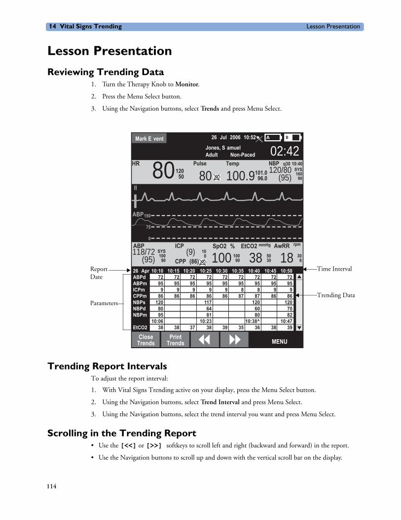
14 Vital Signs Trending Lesson Presentation
Lesson Presentation
Reviewing Trending Data1. Turn the Therapy Knob to Monitor.
2. Press the Menu Select button.
3. Using the Navigation buttons, select Trends and press Menu Select.
Trending Report IntervalsTo adjust the report interval:
1. With Vital Signs Trending active on your display, press the Menu Select button.
2. Using the Navigation buttons, select Trend Interval and press Menu Select.
3. Using the Navigation buttons, select the trend interval you want and press Menu Select.
Scrolling in the Trending Report• Use the [<<] or [>>] softkeys to scroll left and right (backward and forward) in the report.
• Use the Navigation buttons to scroll up and down with the vertical scroll bar on the display.
Mark E vent 26 Jul 2006 10:52
Jones, S amuelAdult Non-Paced 02:42
100.980 120/80(95)
Pulse NBP q30 10:40TempSYS160
90
II
HR 8012050 101.0
96.0
SpO2 % EtCO2
100AwRRmmHg rpmICP
CPP (86)
ABP
150
75
0
ABP
100SYS118/72
(95) 90(9) 100
90
100 38 50
30 18 308
CloseTrends
PrintTrends MENU
26 Apr 10:10 10:15 10:20 10:25 10:30 10:35 10:40 10:45 10:50ABPd 72 72 72 72 72 72 72 72 72ABPm 95 95 95 95 95 95 95 95 95ICPm 9 9 9 9 9 8 8 9 9 CPPm 86 86 86 86 86 87 87 86 86NBPs 120 117 120 120 NBPd 80 64 60 70 NBPm 95 81 80 82 10:06 10:23 10:38^ 10:47EtCO2 38 38 37 38 39 35 36 38 39
Time Interval
Trending Data
ReportDate
Parameters
114

Lesson Presentation 14 Vital Signs Trending
Printing the Trending ReportPrint the Trending Report two ways:
1. Press the soft key under the Print Trends label. A report for the displayed period and interval is printed.
2. Press the Summary button, select Trends, and then Trends Interval. A report for the entire incident period is printed.
Exiting the Trending ReportTo exit the Trending Report and return to a waveform display, simply press the [Close Trends] soft key. You will be returned to Monitor Mode.
Practice Exercise 1Change report time intervals, scroll through data, and print out sample reports.
Questions
1. Does the layout of a report change in any way when you increase or decrease the time interval?
2. Does the information on a printout differ from what you see on the display?
Notes:
________________________________________________________________
________________________________________________________________
________________________________________________________________
________________________________________________________________
________________________________________________________________
115

14 Vital Signs Trending Review
ReviewPlease answer the following questions related to the Vital Signs Trending Report.
1. Which of the following statement(s) are TRUE regarding data displayed on the Trending Report?
a. If you scroll left to view older data, the screen will not update to new data when available.
b. Questionable data is indicated by -?-.
c. Unavailable data is indicated by an empty space.
d. A ^ after the timestamp indicates multiple measurements taken during the interval.
2. For the one-minute time interval, data from continuous measurements is the average reading for that one-minute period. T or F
116

15
User Training Workbook
15IntelliVue Networking
Lesson IntroductionThis lesson describes the HeartStart MRx’s IntelliVue Networking Option.
ObjectivesUpon completion of this lesson, you should be able to:
1. Identify IntelliVue Networking display data.
2. Identify how to connect the MRx to the IntelliVue Network.
3. Admit, discharge, and transfer patients to or from the Philips IntelliVue Information Center.
4. Share information and data with the Information Center.
117
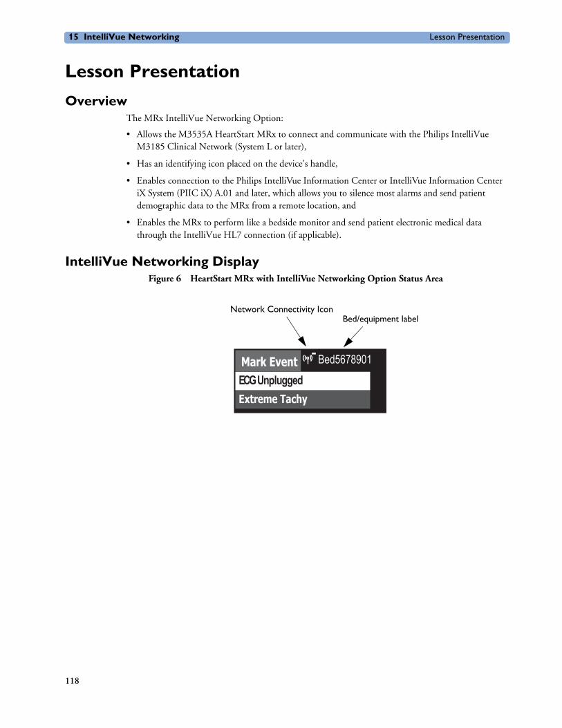
15 IntelliVue Networking Lesson Presentation
Lesson Presentation
OverviewThe MRx IntelliVue Networking Option:
• Allows the M3535A HeartStart MRx to connect and communicate with the Philips IntelliVue M3185 Clinical Network (System L or later),
• Has an identifying icon placed on the device’s handle,
• Enables connection to the Philips IntelliVue Information Center or IntelliVue Information Center iX System (PIIC iX) A.01 and later, which allows you to silence most alarms and send patient demographic data to the MRx from a remote location, and
• Enables the MRx to perform like a bedside monitor and send patient electronic medical data through the IntelliVue HL7 connection (if applicable).
IntelliVue Networking DisplayFigure 6 HeartStart MRx with IntelliVue Networking Option Status Area
Extreme Tachy
Mark Event Bed5678901
ECG Unplugged
Network Connectivity IconBed/equipment label
118

Lesson Presentation 15 IntelliVue Networking
Table 2 Icon Definitions
Notes:
________________________________________________________________
________________________________________________________________
________________________________________________________________
________________________________________________________________
________________________________________________________________
Symbol Definition
No symbol No connection/association with the Information Center is established.
Connected. A wired connection is established. The MRx is assigned to a sector and is being monitored by the Information Center.
Connected. A wireless connection is established. The MRx is assigned to a sector and is being monitored by the Information Center.
119
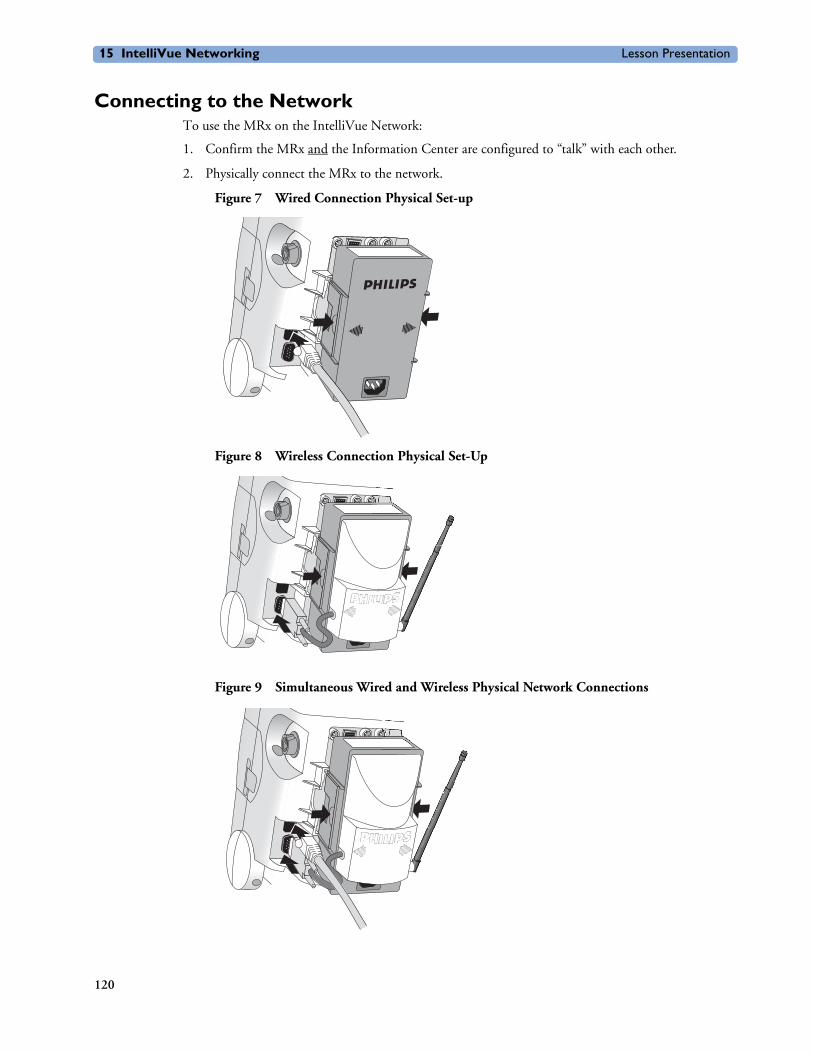
15 IntelliVue Networking Lesson Presentation
Connecting to the NetworkTo use the MRx on the IntelliVue Network:
1. Confirm the MRx and the Information Center are configured to “talk” with each other.
2. Physically connect the MRx to the network.
Figure 7 Wired Connection Physical Set-up
Figure 8 Wireless Connection Physical Set-Up
Figure 9 Simultaneous Wired and Wireless Physical Network Connections
120

Lesson Presentation 15 IntelliVue Networking
Note:
– The radio/AC module must be fully connected before turning on the MRx.
– If you lose the wired connection, the MRx automatically attempts to connect to the network via the wireless radio/AC module. If the radio/AC module is not connected to the MRx, plug the module in and restart the MRx to obtain a wireless connection.
Using the Device Location Option (optional topic)• Identifies the general location of the MRx by associating it with network access points installed in
the healthcare facility
• Not intended for use when attempting to locate a patient
Network Settings (optional topic)To view current network settings in Monitor, Pacer, and Manual Defib modes:
1. Press the Menu Select button.
2. Using the Navigation buttons, select Other and press Menu Select.
3. Select Network Settings and press Menu Select.
Table 3 Network Settings Parameters
Notes:
________________________________________________________________
________________________________________________________________
________________________________________________________________
________________________________________________________________
________________________________________________________________
Field Description
Connection Displays current connection status: Wired, Wireless, or Inactive
MAC Address HeartStart MRx MAC address
MAC Instr. Tele. Instrument Telemetry Radio Module MAC address
RF Access Code Used to identify which RF channel the HeartStart MRx-Information Center communications use (Set in Configuration Mode.)
IP Address Current IP address - HeartStart MRx (wired) or Radio Module (wireless)
Server IP Information Center IP address
Subnet Mask Subnet mask of wired or wireless network
RSSI Instrument Telemetry Radio’s Received Signal Strength Indicator (Value updates while window is open)
121
15 IntelliVue Networking Lesson Presentation
Patient Admit, Discharge, and Transfer
AdmitTo admit a patient from the MRx:
1. Press the Menu Select button.
2. Using the Navigation buttons, select Patient Info and press Menu Select.
3. Select Name, ID, Date Of Birth or Sex and press Menu Select.
4. Enter the appropriate information and press Menu Select.
A Patient Admitted momentary message displays on the MRx when a patient is admitted.
Note: The above procedure is easier to accomplish at the Information Center.
Practice Exercise 1Admit a patient on the MRx to the Information Center.
Questions
1. What is displayed on the MRx and Information Center once you complete the patient admittance? Is there any difference in the format of the information displayed between the MRx and Information Center?
DischargeTo discharge a patient:
1. Press the Menu Select button.
2. Using the Navigation buttons, select Patient Info and press Menu Select.
3. Select Discharge Patient and press Menu Select.
4. The MRx displays one of two Discharge Patient messages and prompts you with a Discharge Patient? question.
5. Select Yes to discharge the patient or No to cancel the discharge.
TransferTo access Transfer:
1. Confirm that the MRx is on the network, not already in Transfer Mode, and the patient has been admitted. (The patient’s name or “---” is displayed.)
2. Press the Menu Select button.
3. Using the Navigation buttons, select Patient Info and press Menu Select.
4. Select Transfer and press Menu Select.
5. The Transfer Patient message prompts you with a Transfer Patient? question.
6. Select Yes to transfer the patient or No to cancel transfer.
122

Lesson Presentation 15 IntelliVue Networking
Transfer ModeTransfer Mode allows hands off of patient data from one monitoring location to another.
Re-admit Patient
To re-admit a patient:
1. Press the Menu Select button.
2. Using the Navigation buttons, select Patient Info and press Menu Select.
3. Select Re-admit and press Menu Select.
4. When Re-admit is selected, a Re-admit Patient message displays, prompting with a Re-admit Patient? question. Select Yes to re-admit the patient or No to cancel re-admission.
Clear Transfer
To exit Transfer Mode after losing network connectivity:
1. While in Transfer Mode, press the Menu Select button.
2. Using the Navigation buttons, select Patient Info and press Menu Select.
3. Select Clear Transfer and press Menu Select.
4. The message “Transfer mode will be exited.” displays when Clear Transfer is selected, prompting with a Clear Transfer? question. Select Yes to clear transfer or No to remain in Transfer Mode
Automatic Re-Admit
If a lost network connection between the MRx and Information Center is restored while in Transfer Mode, the patient is automatically re-admitted from the transfer list.
Turning the MRx off
When the MRx is turned off or enters a non-clinical mode while in Transfer Mode, the current patient incident is closed and the MRx exits Transfer Mode.
Notes:
________________________________________________________________
________________________________________________________________
________________________________________________________________
________________________________________________________________
________________________________________________________________
123
15 IntelliVue Networking Lesson Presentation
Sharing Information on the Network
Patient InformationUpdates
After the MRx makes a network connection with the Information Center, patient information entered at one location is automatically reflected at the other.
Date Of Birth
To enter the date of birth:
1. Press the Menu Select button.
2. Using the Navigation buttons, select Patient Info and press Menu Select.
3. Select Date Of Birth and press Menu Select.
– If the patient type is adult, the default menu option is the current date, 50 years ago.
– If the patient type is pediatric, the default menu option is the current date, 7 years ago.
4. Using the Navigation buttons, enter the date of birth and press Menu Select.
Date and Time
Whenever the MRx’s date and time are not in agreement with the Information Center, the MRx automatically synchronizes its date and time to match the Information Center’s.
Conflict Handling• Conflicting patient information between the Information Center and the MRx is automatically
resolved when the MRx associates with the Information Center. If patient information on the MRx has changed as a result of a resolution, you can confirm or edit the information via a menu.
– To confirm the information, press Menu Select.
– To edit patient info, highlight Edit Patient Info and press Menu Select to display the Edit Patient Info menu. Any selection from this menu brings up a screen for modifying the selection. After modifying the information, the Patient Information merged menu reappears with the new patient information included. The Information Center is also updated with the modified information.
• If the MRx is connected to the PIIC iX and the PIIC iX can determine the likely outcome of the conflict, you answer a Smart Question to help resolve the conflict. If the PIIC iX cannot determine the likely resolution or if you answer No to the Smart Question, you have as many as four options to resolve the conflict via appropriate patient demographic changes.
Viewing Patient Incident Data • While at the Information Center, you can view patient incident data sent from the MRx. Refer to
the IntelliVue M3150 Information Center Instructions for Use for details.
• Up to 30 single-valued and/or tripled-valued parameters, up to four waveforms (excluding Q-CPR compression waveform), and up to seven alarms are viewable at the Information Center.
124
Lesson Presentation 15 IntelliVue Networking
Alarms• If configured, you can silence/reset most MRx alarms and INOPs from the Information Center.
Alarms re-sound after two minutes if a condition is not cleared.
• Pacing Stopped (occurring when leads or pads off), Batteries Low, and Defib Shutdown alarms result in Red INOPs that cannot be silenced at the Information Center. The Pacer Output Low alarm results in a Yellow INOP that cannot be silenced at the Information Center. All four alarms must be silenced at the MRx.
Printing• The MRx prints to the installed 50mm or 75mm printer, not to a printer located on the institution’s
network.
• Alarm recordings are configured at the MRx and sent to the Information Center central recorder (if present), where they can be recorded from the Record/Store tab under All Controls.
• Vital Signs Trending Reports generated by the MRx can only be printed at the MRx.
• Patient data on the Information Center can be printed from the Information Center.
Turning a Networked Device Off• If a networked MRx is turned off, wave and alarm data may be displayed at the Information Center
for 10 more seconds. After 10 seconds, a No data from bed INOP statement appears on the Information Center display. The current patient incident is closed at the MRx but the patient will not be discharged from the Information Center.
If the MRx is turned back on, the ADT state is initially set to Not Admitted and patient type, paced status and alarm limits are reset to their default settings. If the patient is still admitted at the Information Center, the MRx is updated with patient information from the Information Center. The ADT state is reset to “admitted.”
• In the event the MRx loses its network connection with the Information Center and both devices are still powered on, the devices retain the patient’s status and other settings when a network connection is restored.
Leaving a Clinical ModeIf a networked MRx is changed to a non-clinical mode*, the current patient incident is closed at the MRx but the patient will not be discharged from the Information Center. If you re-enter a clinical mode, the ADT state is initially set to Not Admitted and patient type (category), paced status and alarm limits are reset to their default settings. If the patient is still admitted at the Information Center, the MRx is updated with patient information from the Information Center. The ADT state is reset to “admitted.”
*Note: Be sure the MRx is not connected to a patient while in a non-clinical mode (e.g., Data Management or Operational Check).
125

15 IntelliVue Networking Lesson Presentation
Events LoggedThe MRx automatically creates an Event Summary for each patient incident.
INOPs, Alarms, and Messages at the Information CenterMost HeartStart MRx alarms, INOPs, and messages display at the Information Center in their entirety or in an abbreviated form.
Notes:
________________________________________________________________
________________________________________________________________
________________________________________________________________
________________________________________________________________
________________________________________________________________
126

Review 15 IntelliVue Networking
ReviewAnswer the following questions related to the IntelliVue Networking option.
1. The IntelliVue Information Center replaces the equipment label on the MRx display with a bed label when the MRx connects to the network. T or F
2. Which of the following statement(s) are FALSE regarding MRx connectivity to the IntelliVue Network?
a. If you connect the radio/AC power module to MRx after you turn it on, it takes 10 seconds for the MRx to detect the module.
b. If a MRx leaves the healthcare facility, disconnect the radio module from the device.
c. If you lose the wired connection, the MRx automatically attempts to connect to the network via the wireless radio/AC module.
d. The MRx provides the same level of network functionality for both wired or wireless connections.
3. Which of the following statement(s) are FALSE regarding patient admittance, discharge, and transfer?
a. The MRx admits patients via patient name, patient ID, patient type, date of birth, or sex.
b. Discharging a patient resets patient type, paced status, and other MRx settings to default values.
c. When a patient transfer is confirmed, the patient is discharged to the transfer list at the Information Center.
d. When the MRx enters a non-clinical mode (e.g., Data Management) while in Transfer Mode, the patient remains on the Information Center’s transfer list.
4. Which of the following statement(s) are TRUE regarding the type of information shared between the MRx and Information Center?
a. A patient’s weight and height entered on the Information Center are automatically updated on the MRx.
b. If the Information Center sends a neonatal patient type to the MRx, the MRx modifies the setting to pediatric.
c. If patient information changes on the MRx due to a conflict resolution, you will see a ’patient information merged’ message and a menu to confirm or edit patient info in all modes.
d. You can silence or reset most MRx alarms and INOPs from the Information Center.
127

15 IntelliVue Networking Review
128

16
User Training Workbook
16Working with Data
Lesson IntroductionThis lesson describes the data management features of the HeartStart MRx.
ObjectivesUpon completion of this lesson, you should be able to:
1. Identify MRx data management features.
2. Identify characteristics associated with printing Event Summaries.
3. Mark patient events.
Notes:
________________________________________________________________
________________________________________________________________
________________________________________________________________
________________________________________________________________
________________________________________________________________
129

16 Working with Data Lesson Presentation
Lesson Presentation
Overview• MRx creates Event Summaries that:
– Have an event ID number and date/time stamp.
– Contain parameter measurements.
– Include trending and associated 12-Lead Reports.
– Are stored in internal memory.
– Can be copied to an external data card.
– Can be transmitted to a remote PC.
– Can be printed out.
• New Event Summaries are initiated:
– on the arrival of a valid ECG signal, SpO2 data, CO2 data, invasive pressure data, temperature data, or CPR meter compression.
– when an NBP measurement is requested.
– when the Charge button is pressed.
– when the Mark Event button is pressed.
• Monitoring and defibrillation functions are disabled in Data Management Mode
Notes:
________________________________________________________________
________________________________________________________________
________________________________________________________________
________________________________________________________________
________________________________________________________________
130
Lesson Presentation 16 Working with Data
Copying from Internal MemoryTo copy Event Summaries and 12-Lead ECG Reports stored in internal memory to an external data card:
1. Insert a data card into MRx.
2. Turn the Therapy Knob to Monitor.
3. Press the Menu Select button.
4. Using the Navigation buttons, select Other and press Menu Select.
Note: Using T.00 software on the MRx M3536A, you can access Data Management Mode by pressing the Summary (i) button, thus eliminating steps 3 and 4 above.
5. Select Data Management and press Menu Select.
6. Press Menu Select to acknowledge the message Leaving Normal Operational Mode.
7. Use the [Prev Item] and [Next Item] soft keys to select an Event Summary.
8. Press Menu Select to display the Data Management menu.
9. Select Copy and press Menu Select.
Note: You can copy all event data or individual 12-Lead Reports at this point in the procedure if you have software Version 9.xx or greater (including Version F.xx).
Viewing and Erasing the External Data CardTo display a list of Event Summary and 12-Lead ECG Reports located on the data card:
1. Turn the Therapy Knob to Monitor.
2. Press the Menu Select button.
3. Using the Navigation buttons, select the Other menu and press Menu Select.
Note: Using T.00 software on the MRx M3536A, you can access Data Management Mode by pressing the Summary (i) button, thus eliminating steps 2 and 3 above.
4. Select Data Management and press Menu Select.
5. Press Menu Select to acknowledge the message Leaving Normal Operational Mode.
6. Press Menu Select to display the Data Management menu.
7. Select View Data Card and press Menu Select.
Use the [Prev Page] and [Next Page] soft keys to navigate to additional display pages. Use the Erase Card menu option to delete the data card contents.
Notes:
________________________________________________________________
________________________________________________________________
________________________________________________________________
131

16 Working with Data Lesson Presentation
Printing During a Patient Event
Event Summaries• Press the Summary button and select Event Summary from the Print menu to print the current or
most recent Event Summary.
Vital Signs Trending Reports• To print the current or previous Vital Signs Trending Report:
– press the Summary button, select Trends and then Trends Interval from the menu,
– press the soft key under the [Print Trends] label while in Trends Mode, or
– select Trends from the Print menu in Data Management Mode.
12-Lead ECG Reports• Print a current individual 12-Lead ECG Report by hitting the [Print] softkey in 12-Lead View.
• To print a recent 12-Lead ECG Report:
1. Press the Menu Select button and highlight Reports.
2. Use the Navigation buttons to highlight the report you want to print.
3. Press Menu Select and highlight Print.
4. Press Menu Select to print the report.
Notes:
________________________________________________________________
________________________________________________________________
________________________________________________________________
________________________________________________________________
________________________________________________________________
132

Lesson Presentation 16 Working with Data
Printing from Data Management ModeTo print a historical Event Summary, Vital Sign Trends Report or 12-Lead Report:
1. Turn the Therapy Knob to Monitor.
2. Press the Menu Select button.
3. Using the Navigation buttons, select the Other menu and press Menu Select.
Note: Using T.00 software on the MRx M3536A, you can access Data Management Mode by pressing the Summary (i) button, thus eliminating steps 2 and 3 above.
4. Select Data Management and press Menu Select.
5. Press Menu Select to acknowledge the message Leaving Normal Operational Mode.
6. Press Menu Select to display the Data Management menu.
7. Use the soft keys labeled [Prev Item] and [Next Item] to select the Event Summary you want to print.
8. Press Menu Select to display the Data Management menu.
9. Highlight Print and press Menu Select.
10. Select the data option listed that you want to print (Event Summary, Trends, or specific 12-Lead Report) and press Menu Select to print.
Note: If you are using a HeartStart MRx M3536A with software version R.03 and later, you can print four different Event Summary report lengths (short, medium, long, or full) based on device configuration.
Marking EventsTo annotate the Event Summary and the ECG strip with an event:
1. Press the Mark Event button.
2. Using the Navigation buttons, select the desired event from the Events menu and press Menu Select.
Notes:
________________________________________________________________
________________________________________________________________
________________________________________________________________
________________________________________________________________
________________________________________________________________
133

16 Working with Data Review
ReviewPlease answer the following questions related to MRx data management.
1. Which of the following statement(s) are TRUE related to MRx’s data management?
a. Data management includes Event Summaries that have a unique event identification number and are automatically stored in internal memory.
b. New Event Summaries are initiated by the arrival of valid SpO2, CO2, or invasive pressure data, along with other activities.
c. The amount of patient data collected is determined by the amount of data card space available.
d. When using the Data Management function, monitoring and defibrillation modes are disabled.
2. If an alarm condition occurs while an Event Summary is printing, any associated ECG waveform is not stored nor is an alarm strip printed. T or F
3. For a ‘Shock delivered’ or ‘Shock failed’ event, the MRx will print a 12-second string, if so configured. T or F
4. The Mark Event button can be configured to print a 6-second ECG strip real time or prepended with the previous 10 seconds of data leading up to the marked event. T or F
134

17
User Training Workbook
17Data Transmission
Lesson IntroductionThis lesson describes how to transmit data from the HeartStart MRx to various external devices using a suite of available data transmission options.
ObjectivesUpon completion of this lesson, students should be able to:
1. Identify characteristics of the MRx data transmission.
2. Set up for Bluetooth transmission. (Optional objective)
3. Transmit a 12-Lead Report.
4. Identify characteristics of a Periodic Clinical Data Transmission. (Optional objective)
5. Identify characteristics of MRx’s Data Management Mode. (Optional objective)
6. Identify characteristics of a Batch LAN Data Transfer. (Optional objective)
Notes:
________________________________________________________________
________________________________________________________________
________________________________________________________________
________________________________________________________________
________________________________________________________________
135
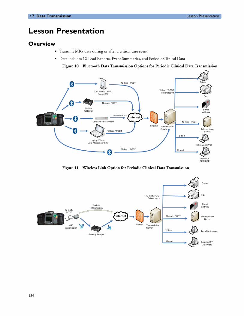
17 Data Transmission Lesson Presentation
Lesson Presentation
Overview• Transmit MRx data during or after a critical care event.
• Data includes 12-Lead Reports, Event Summaries, and Periodic Clinical Data
Figure 10 Bluetooth Data Transmission Options for Periodic Clinical Data Transmission
Figure 11 Wireless Link Option for Periodic Clinical Data Transmission
Internet
MobileGateway
LandLine / BT Modem
Laptop / TabletData Messenger S/W
Cell Phone / PDAPocket PC
12-lead / PCDT
12-lead / PCDT
12-lead / PCDT
Firewall TelemedicineServer
Printer
Fax
E-mailaddress
12-lead / PCDTPatient report
`
TraceMasterVue
`
Datamed FTGE MUSE
TelemedicineServer
12-lead / PCDT
12-lead / PCDT
12-lead
12-lead
12-lead / PCDT
Internet
Firewall TelemedicineServer
12-lead / PCDTPatient report
`
`
12-lead / PCDT
12-lead
12-lead
12-lead /PCDT
WiFitransmission
Cellulartransmission
Printer
Fax
E-mailaddress
TelemedicineServer
TraceMasterVue
Datamed FTGE MUSE
Gateway/hotspot
136

Lesson Presentation 17 Data Transmission
Notes:
________________________________________________________________
________________________________________________________________
________________________________________________________________
________________________________________________________________
________________________________________________________________
137

17 Data Transmission Lesson Presentation
Preparing for Transmission• Set up the MRx based on the type of transmission option selected (e.g., Bluetooth wireless, Wireless
Link, Batch LAN Data transfer).
• Test the transmission before using in a clinical situation.
• Waveforms for all monitored parameters can be viewed during the transmission process; however, the waveform appearing in Wave Sector 4 is partially obscured when the transmission status bar is displayed. Related alarms, measurements, and INOP messages remain active and are reported in Parameter Blocks 1 and 2 and the general status area.
• The MRx transmits data from internal memory only.
Modifying Reference IDsTo change the Reference ID of an MRx during an event:
1. Press the Menu Select button.
2. Use the Navigation buttons to highlight Other and press Menu Select.
3. Highlight Reference IDs and press Menu Select.
4. Select the Reference ID you want to use or Other to add an additional Reference ID.
Notes:
________________________________________________________________
________________________________________________________________
________________________________________________________________
________________________________________________________________
________________________________________________________________
138
Lesson Presentation 17 Data Transmission
Setting Up Bluetooth Transmissions (Optional topic)
Adding a Bluetooth DeviceTo add a Bluetooth device to the list of transmission devices:
1. Access 12-Lead Mode and press the Menu Select button.
2. From the 12-Lead Main Menu, select Bluetooth Devices and press Menu Select.
3. Select Add Device and press Menu Select. The message Searching for Bluetooth Devices displays. The search lasts for 30 seconds.
4. From the Add Device menu, select the desired Bluetooth device and press Menu Select.
The selected Bluetooth device must now go through the “pairing” process described below.
Pairing a Bluetooth Device and Selecting a ProfileTo pair a Bluetooth device with the MRx:
1. Use the Navigation buttons to enter the passkey on the MRx and select Done.
Note: The passkey is like a PIN number or password you create for a personal account.
2. Enter the same passkey on your Bluetooth device. See the documentation that came with your Bluetooth device for instructions.
3. Select a Bluetooth Service.. Highlight File Transfer or Dial-Up Networking and press the Menu Select button.
4. If you selected DUN, select the designated profile from the Phone/Modem Profiles menu. If you selected FT, proceed to the next step.
5. Once the Bluetooth device is paired with the MRx and the profile selected, the MRx performs a transmission test. After successfully connecting, the message Transmission Test Passed displays. Press Menu Select to acknowledge the message. If the transmission test fails, the message Transmission Test Failed displays, along with additional information about where the failure occurred. See “Transmission Problems (Bluetooth)” in the Troubleshooting chapter of the MRx Instructions for Use for support on failures.
Changing a Bluetooth ProfileTo change a Bluetooth device profile:
1. In 12-Lead Mode, press Menu Select.
2. From the 12-Lead Main Menu, select Bluetooth Devices and press Menu Select. A list of configured Bluetooth devices displays.
3. Use the Navigation buttons to select a device and press Menu Select.
4. Select Change Profile and press Menu Select. A menu of configured profiles for that device displays, with the current associated profile highlighted.
5. Select the profile you want to associate with the device.
The MRx tests the profile to determine if the Bluetooth device can communicate with the 12-Lead Transfer Station. If successful. press Menu Select to acknowledge the message. If unsuccessful, the message Transmission Test Failed displays, along with additional information about where the
139
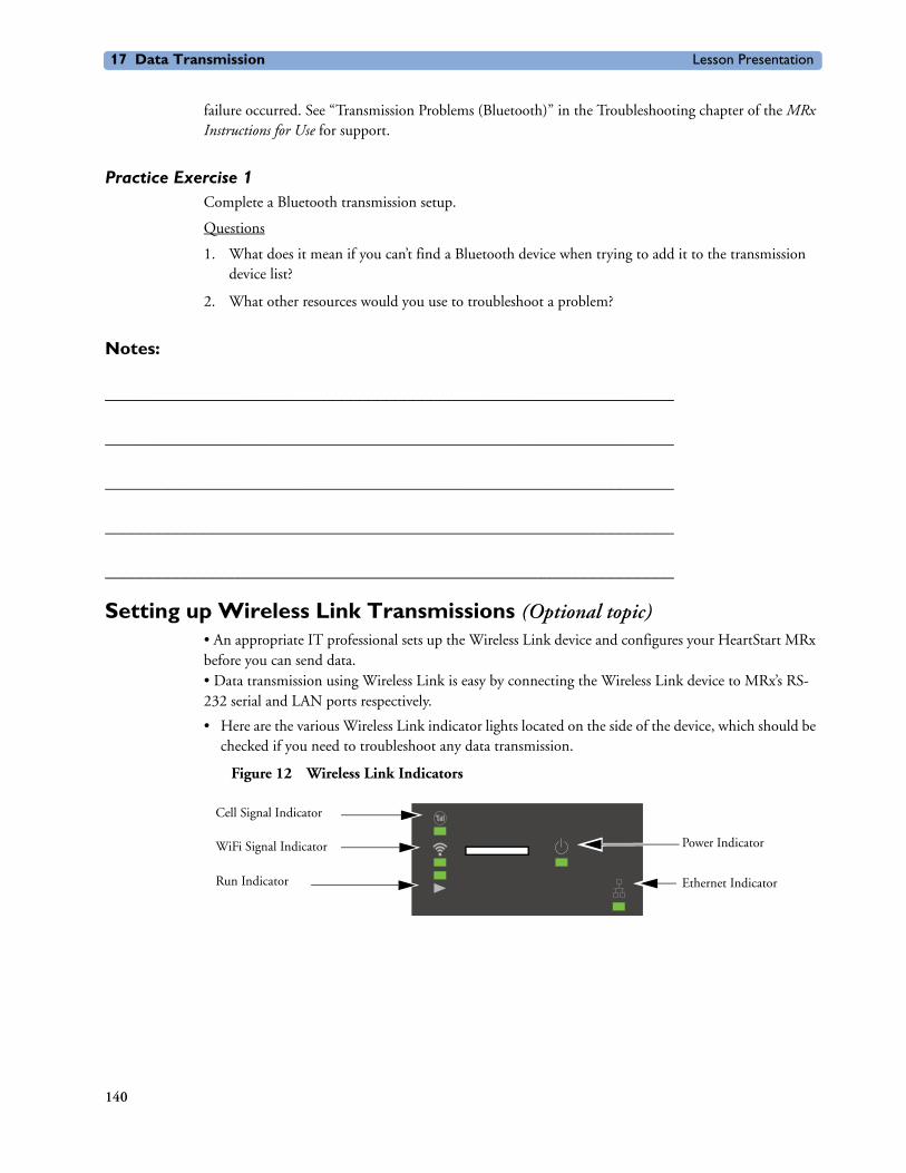
17 Data Transmission Lesson Presentation
failure occurred. See “Transmission Problems (Bluetooth)” in the Troubleshooting chapter of the MRx Instructions for Use for support.
Practice Exercise 1Complete a Bluetooth transmission setup.
Questions
1. What does it mean if you can’t find a Bluetooth device when trying to add it to the transmission device list?
2. What other resources would you use to troubleshoot a problem?
Notes:
________________________________________________________________
________________________________________________________________
________________________________________________________________
________________________________________________________________
________________________________________________________________
Setting up Wireless Link Transmissions (Optional topic)• An appropriate IT professional sets up the Wireless Link device and configures your HeartStart MRx before you can send data. • Data transmission using Wireless Link is easy by connecting the Wireless Link device to MRx’s RS-232 serial and LAN ports respectively.
• Here are the various Wireless Link indicator lights located on the side of the device, which should be checked if you need to troubleshoot any data transmission.
Figure 12 Wireless Link Indicators
Power Indicator
Ethernet Indicator
Cell Signal Indicator
Run Indicator
WiFi Signal Indicator
140

Lesson Presentation 17 Data Transmission
Notes:
________________________________________________________________
________________________________________________________________
________________________________________________________________
________________________________________________________________
Transmitting in 12-Lead ModeTo transmit a displayed 12-Lead Report:
1. From the 12-Lead Report screen, press the Menu Select button.
2. Select Send and press Menu Select.
3. Select the report destination from the Send To menu and press Menu Select.
4. Highlight the device you want to use and press Menu Select.
Transmitting to a Fax NumberTo transmit a displayed 12-Lead Report to a manually entered fax number:
1. Press Menu Select.
2. Using the Navigation buttons if necessary, select Send from the 12-Lead Main Menu and press Menu Select.
3. Select Fax Number from the Send To menu.
4. Enter the fax number from the numeric list using the Navigation buttons. Include any extra digits necessary (e.g., 9 for an outside line or 1 plus the area code for long distance).
5. Select Done and press Menu Select.
Transmitting to a Personal Computer• Using Bluetooth FTP, the MRx can send 12-leads and periodic data to a PC during an event and
send event summaries to a PC after an event.
• Transfer data is used by an ePCR or Event Review Pro on the receiving personal computer or forwarded on to a remote destination using HeartStart Data Messenger software.
Practice Exercise 2Complete a transmission in 12-Lead Mode to a configured site, fax number, and/or PC.
1. What display changes do you see when completing each transmission procedure?
2. What differences exist between each procedure?
141
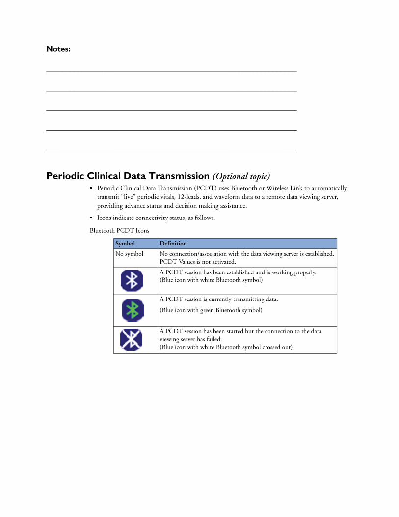
Notes:
________________________________________________________________
________________________________________________________________
________________________________________________________________
________________________________________________________________
________________________________________________________________
Periodic Clinical Data Transmission (Optional topic)• Periodic Clinical Data Transmission (PCDT) uses Bluetooth or Wireless Link to automatically
transmit “live” periodic vitals, 12-leads, and waveform data to a remote data viewing server, providing advance status and decision making assistance.
• Icons indicate connectivity status, as follows.
Bluetooth PCDT Icons
Symbol Definition
No symbol No connection/association with the data viewing server is established. PCDT Values is not activated.
A PCDT session has been established and is working properly.(Blue icon with white Bluetooth symbol)
A PCDT session is currently transmitting data.
(Blue icon with green Bluetooth symbol)
A PCDT session has been started but the connection to the data viewing server has failed.(Blue icon with white Bluetooth symbol crossed out)
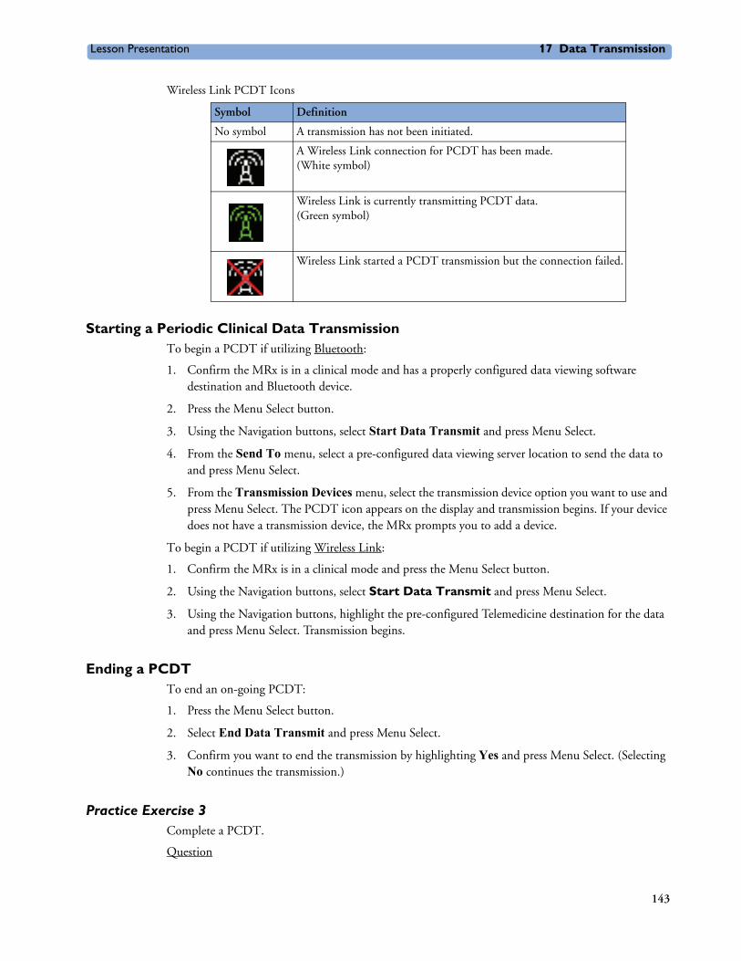
Lesson Presentation 17 Data Transmission
Wireless Link PCDT Icons
Starting a Periodic Clinical Data TransmissionTo begin a PCDT if utilizing Bluetooth:
1. Confirm the MRx is in a clinical mode and has a properly configured data viewing software destination and Bluetooth device.
2. Press the Menu Select button.
3. Using the Navigation buttons, select Start Data Transmit and press Menu Select.
4. From the Send To menu, select a pre-configured data viewing server location to send the data to and press Menu Select.
5. From the Transmission Devices menu, select the transmission device option you want to use and press Menu Select. The PCDT icon appears on the display and transmission begins. If your device does not have a transmission device, the MRx prompts you to add a device.
To begin a PCDT if utilizing Wireless Link:
1. Confirm the MRx is in a clinical mode and press the Menu Select button.
2. Using the Navigation buttons, select Start Data Transmit and press Menu Select.
3. Using the Navigation buttons, highlight the pre-configured Telemedicine destination for the data and press Menu Select. Transmission begins.
Ending a PCDTTo end an on-going PCDT:
1. Press the Menu Select button.
2. Select End Data Transmit and press Menu Select.
3. Confirm you want to end the transmission by highlighting Yes and press Menu Select. (Selecting No continues the transmission.)
Practice Exercise 3Complete a PCDT.
Question
Symbol Definition
No symbol A transmission has not been initiated.
A Wireless Link connection for PCDT has been made. (White symbol)
Wireless Link is currently transmitting PCDT data. (Green symbol)
Wireless Link started a PCDT transmission but the connection failed.
143

17 Data Transmission Lesson Presentation
What display changes do you see during the procedure?
Notes:
________________________________________________________________
________________________________________________________________
________________________________________________________________
________________________________________________________________
________________________________________________________________
144
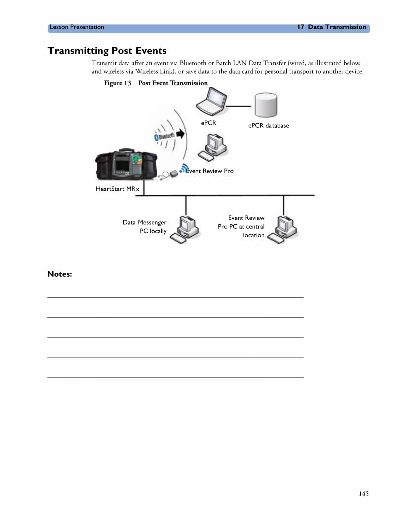
Lesson Presentation 17 Data Transmission
Transmitting Post EventsTransmit data after an event via Bluetooth or Batch LAN Data Transfer (wired, as illustrated below, and wireless via Wireless Link), or save data to the data card for personal transport to another device.
Figure 13 Post Event Transmission
Notes:
________________________________________________________________
________________________________________________________________
________________________________________________________________
________________________________________________________________
________________________________________________________________
ePCR
Event Review Pro
HeartStart MRx
Data MessengerPC locally
ePCR database
Event ReviewPro PC at central
location
145

17 Data Transmission Lesson Presentation
Transmitting in Data Management ModeTo transmit an Event Summary or 12-Lead Report from internal memory to a receiving device via Bluetooth FTP:
1. Press the Menu Select button.
2. Using the Navigation buttons, select Other and press Menu Select.
Note: Using T.00 software on the MRx M3536A, you can access Data Management Mode by pressing the Summary (i) button.
3. Select Data Management and press Menu Select.
4. Press Menu Select to acknowledge the message Leaving Normal Operational Mode.
5. Using the [Prev Item] and [Next Item] softkeys, highlight the Event Summary you want to transmit (or the Event Summary which contains the 12-Lead Report you want to transmit) and press Menu Select.
6. Highlight Send and press Menu Select.
7. Highlight the type of data you want to transmit on the Send menu and press Menu Select.
8. Depending upon which option you selected in Step 7, you are presented with different menus.
– If you selected a 12-Lead Report:
a. Select a destination for the 12-Lead Report from the Send To menu and press Menu Select.
b. If your device has more than one configured transmission device, highlight the transmission device you want to use and press Menu Select.
– If you selected an Event Summary:
If your device is configured with just one transmission device, transmission begins. If your device has more than one configured transmission device, highlight the option you want to use and press Menu Select.
Notes:
________________________________________________________________
________________________________________________________________
________________________________________________________________
________________________________________________________________
________________________________________________________________
146

Lesson Presentation 17 Data Transmission
Tracking Data TransmissionData transmission progress is displayed on the MRx, as follows:
• For events - Event ID, date, and time
• For 12-Lead reports - date and time
• The phrases Connecting to Device and Sending
• A percentage complete when MRx is sending data
• Once transmission is complete - Confirming. Stand by... message, followed by a Disconnecting message
Cancelling a TransmissionCancel a transmission in progress.
1. From either 12-Lead Mode or Data Management Mode, press the Menu Select button.
2. Highlight Cancel Transmission and press Menu Select.
3. Select Yes and press Menu Select to cancel or No and press Menu Select to continue the transmission.
Queuing Transmissions• Queue more than one 12-Lead Report or Event Summary for a non-BLDT transmission using the
same transmission device.
• Queue 12-Lead Reports to the same or different locations.
• Queue another transmission while a transmission is in progress.
• Complete the first transmission before initiating the next one if transmitting using different transmission devices,
• Queued transmissions are cancelled when a transmission fails or is cancelled.
Finding Transmission Results• Data transmitted from the MRx to a receiving device is placed in a “philipsMRx” folder and,
depending on the data sent, a sub-folder: “12-Leads” or “events”.
Practice Exercise 4Complete a transmission in Data Management Mode for a single Event Summary, all summaries, or a single 12-Lead Report, as appropriate.
Question
What display changes do you see during any of the transmission procedures?
147

17 Data Transmission Lesson Presentation
Notes:
________________________________________________________________
________________________________________________________________
________________________________________________________________
________________________________________________________________
________________________________________________________________
148
Lesson Presentation 17 Data Transmission
Batch LAN Data Transfer (Optional topic)• Batch LAN Data Transfer (BLDT) enables you to download either a single Event Summary or all
Event Summaries from the internal data card to an external personal computer running Data Messenger software for further review and archiving. When you download all summaries, they are erased from the MRx automatically.
• Data Messenger software communicates with the MRx to download Event Summaries, storing them in a folder locally or forwarding files to a remote Event Review Pro computer.
Setting Up for Batch LAN Data Transfer• Connect a cable from the LAN port on the back of the MRx to either a router or Network Interface
Card (NIC) on a local personal computer. Ask your IT support how your setup has been configured.
• Alternatively, accomplish BLDT using Wireless Link. Make sure that a PC running Data Messenger is connected to the same WiFi network as the MRx. Confirm with your IT support which wireless network you've been configured for.
Transferring Files with BLDTTo transfer data using the BLDT option:
1. Confirm the MRx is in Data Management Mode, Data Messenger is running on the receiving personal computer (as indicated by the Data Messenger icon in the task bar), and the LAN cable (or Wireless Link device) is securely connected to the MRx. For wireless transmission, the PC is on the same WiFi network as the MRx.
Note: When Wireless Link is used in access point mode (which is the standard configuration for sending cases to ePCRs), it will only broadcast its SSID when in Data Management mode. So, you need to ensure that they are connected to the same network as MRx when in Data Management mode.
2. Once the LAN cable is connected, the HeartStart MRx automatically communicates with the Data Messenger personal computer and prompts you to send data.For wireless transmission, once the MRx is in Data Management mode, the MRx automatically displays the Send menu once it has successfully communicated with the Data Messenger. This can take between 30-60 secs. During this time, you will observe a connecting message on the MRx.
• Once the transfer begins, the MRx tracks progress indicating the number of files sent and the percent complete.
• Press Menu Select to acknowledge the Transmission Complete message.
To transfer a single event:
3. Use the [Prev Item] and [Next item] softkeys to highlight the correct Event Summary to download.
4. Select Send Selected and press Menu Select.
5. Select the type of data you wish to download and press Menu Select.
To transfer all events:
3. Select Send All and press Menu Select.
149

17 Data Transmission Lesson Presentation
Cancelling a BLDTTo cancel a BLDT:
1. Press the Menu Select button, select Cancel Transmission, and press Menu Select.
Practice Exercise 5Complete a BLDT.
Question
What display changes do you see during the transfer?
Notes:
________________________________________________________________
________________________________________________________________
________________________________________________________________
________________________________________________________________
________________________________________________________________
150
Review 17 Data Transmission
ReviewAnswer the following questions related to data transmission from the HeartStart MRx to various external devices.
1. True or false? Excluding Wireless Link transmissions, MRx requires Bluetooth wireless technology to transmit a 12-Lead ECG to a personal PC.
2. Which one of the following statements is TRUE? To establish communication between a Bluetooth device and the MRx, a pass key is needed for:
a. only the Bluetooth device.
b. only the MRx
c. both the Bluetooth device and MRx.
3. Which one of the following statements is FALSE regarding 12-Lead Report transmission?
a. You can transmit reports to printers, fax machines, PDAs, and cell phones.
b. The MRx transmits reports from internal memory only.
c. If you are transmitting to a fax number, you may need to include a “9” for an outside line or “1” before the area code.
d. You must wait for one transmission to complete before initiating another one.
4. Which of the following statements is FALSE regarding Periodic Clinical Data Transmission?
a. A blue icon with a green Bluetooth symbol indicates a PCDT session is currently transmitting data.
b. All transmitted personal patient-identifiable data is encrypted to insure patient confidentiality.
c. For multiple transmissions, event summary transmissions are sent first, patient vital signs transmissions second, and 12-Lead Report transmissions third.
d. If you start a PCDT within 10 seconds of turning the MRx on, the first transmission contains no wave data.
5. True or false? The Send menu option transmits periodic clinical data if you are in clinical mode.
6. True or false? You can transmit all event data, a specific 12-Lead Report, audio data, and Q-CPR data from Data Management Mode.
7. Which of the following statements is FALSE regarding BLDT?
a. Batch LAN Data Transfer is simply a LAN cable between the MRx and a router or personal computer.
b. Data Messenger software serves as communication software between the MRx and PC.
c. You can queue a second BLDT while the first transfer is in progress.
d. After successfully sending all Event Summaries at once via BLDT, MRx’s internal memory card is erased.
151

17 Data Transmission Review
152

18
User Training Workbook
18Maintenance
Lesson IntroductionThis lesson describes how to care for your HeartStart MRx and includes a brief look at battery maintenance and cleaning.
ObjectivesUpon completion of this lesson, you should be able to:
1. Identify the meaning of each Ready For Use status.
2. Identify the appropriate steps to complete a shift check.
3. Perform the necessary steps to complete an operational check on the MRx.
4. Identify the appropriate steps related to battery maintenance.
5. Identify the appropriate steps to clean the MRx and its associated accessories.
Notes:
________________________________________________________________
________________________________________________________________
________________________________________________________________
________________________________________________________________
________________________________________________________________
153

18 Maintenance Lesson Presentation
Lesson Presentation
Automated TestsThree automated tests assess MRx’s operational performance and notify you of any problems.
• Hourly: Tests batteries, internal power supplies, and internal memory.
• Daily: Tests batteries, internal power supplies, internal memory, internal clock battery, defibrillation, pacing, monitoring parameters, Bluetooth, and printer.
• Weekly: Performs the Daily test and delivers a high energy internal discharge to further exercise the defibrillation circuitry.
Test results include Pass, Fail/DX (device error that may affect therapy), Fail/BF (battery failure), and Fail/D (device error that does not affect therapy).
Ready For Use IndicatorThe Ready For Use (RFU) indicator provides four statuses:
– Blinking black hourglass: sufficient battery power and is ready for use.
– Blinking red “X” with or without a periodic chirp: low battery or no battery.
– Solid red “X” and a periodic chirp: device failure that may prevent shock delivery, pacing, or ECG acquisition.
– Solid red “X” without a periodic chirp: no power or device failure.
Notes:
________________________________________________________________
________________________________________________________________
________________________________________________________________
________________________________________________________________
________________________________________________________________
________________________________________________________________
154
Lesson Presentation 18 Maintenance
Shift Check• The American Heart Association (AHA) recommends completion of a checklist (shift check) at the
beginning of each change in personnel to ensure that defibrillators are ready when needed.
• Checklist activities include:
– Device exterior
– Cables
– Connectors
– Paddles/Pads
– Monitoring electrodes
– Batteries
– AC/DC power
– Printer paper
– Data card
– SpO2 sensor
– NBP cuffs and tubing
– CO2 FilterLine
– Invasive pressure transducer– Temperature sensor
– CPR meter (or Compression Sensor for MRxs running software version 9.xx or lower)
– CPR meter adhesive pads (or Compression Sensor adhesive pads for MRxs running software version 9.xx or lower)
Weekly Shock TestPerform either a weekly shock test or an Operational Check (Op Check) once a week to verify the ability to deliver defibrillation therapy. To perform a weekly shock test:
1. If using:
– External paddles: Make sure the paddles and the paddle tray are thoroughly clean, there is no debris or residue (including all conductive material) on the electrode surfaces of the paddles and tray, the paddles are secure in their trays, and the Patient Contact Indicator (PCI) LEDs located on the sternum paddle are not lit. If the LEDs light, adjust the paddles in their pockets. If the LEDs continue to light, clean both the adult and pediatric paddle electrode surfaces.
Also, if the MRx has the Pacing option, test external paddles using the Weekly Shock test. You must run Operational Check with a pads cable in order to pass the Pacer test.
– Multifunction electrode pads: attach a test load to the end of the patient Therapy cable.
2. Turn the Therapy knob to 150J.
3. Press the Charge button.
If it is necessary to disarm the defibrillator, press the [Disarm] soft key.
4. If using:
– External paddles: simultaneously press the shock buttons located on the paddles to deliver a shock into the paddle tray.
– Pads: press the Shock button on the MRx to deliver a shock into the test load.
155

18 Maintenance Lesson Presentation
5. Confirm on the strip print that the energy delivered to the test load is 150J + 23J (127J to 173J). If not, take the device out of use and call for service.
Note: Detach the test load from the patient Therapy cable after performing the shock test.
Operational CheckThe Op Check verifies performance of a variety of device features, functions, and accessories.
To perform the Op Check:
1. Insert a charged battery (capacity of 20% or greater).
2. Turn the Therapy Knob to Monitor.
3. Press the Menu Select button.
4. Using the Navigation buttons, select Other and press Menu Select.
5. Select Operational Check and press Menu Select.
6. Select Run Op Check and press Menu Select.
7. Press Menu Select to acknowledge the Leaving Normal Operating Mode message.
8. Read and respond to setup instructions.
9. Read and respond to applicable test prompts.
Notes:
________________________________________________________________
________________________________________________________________
________________________________________________________________
________________________________________________________________
________________________________________________________________
________________________________________________________________
________________________________________________________________
156

Lesson Presentation 18 Maintenance
Operational Check SummaryTo display and print an Operational Check Summary:
1. Turn the Therapy Knob to Monitor.
2. Press the Menu Select button.
3. Using the Navigation buttons, select Other and press Menu Select.
4. Select Operational Check and press Menu Select.
5. Using the Navigation buttons, select Op Check Summary and press Menu Select.
6. Press Menu Select to acknowledge the message Leaving Normal Operating Mode.
The Operational Check Summary screen is displayed.
7. Press the [Print] soft key to print the report.
Notes:
________________________________________________________________
________________________________________________________________
________________________________________________________________
157

18 Maintenance Lesson Presentation
Battery Maintenance
Notes:
________________________________________________________________
________________________________________________________________
________________________________________________________________
________________________________________________________________
________________________________________________________________
________________________________________________________________
Activity: When to Perform:
Perform a visual inspection. As part of the Operational Check
Charge the battery. Upon receipt, after use, or if the message Batteries Low is displayed
Perform a calibration. When the Operational Check test results state Calibration Recommended, or every 6 months, whichever comes first
Store batteries in a state of charge in the range of 20% - 40%.
When not in use for an extended period of time
Discard the battery. When there are visual signs of damage or calibration reports less than 80% capacity
158

Lesson Presentation 18 Maintenance
Cleaning Instructions• Use isopropyl alcohol, mild soap and water, chlorine bleach, or quaternary ammonium compounds
on the exterior surfaces of the HeartStart MRx, as well as the batteries and data card.
• Use a soft cloth on the display to prevent scratching.
• The MRx, along with its accessories and supplies, may not be autoclaved, ultrasonically cleaned, or immersed unless otherwise indicated in the MRx Instructions for Use that accompany the accessories and supplies.
• Do not use abrasive cleaners or strong solvents such as acetone or acetone-based cleaners.
• Do not mix disinfecting solutions (such as bleach and ammonia) as hazardous gases may result.
• Do not clean electrical contacts or connectors with bleach.
• Disinfect the device as determined by your organization’s policy to avoid long-term damage to the device.
• To clean the printer printhead:
1. Push the printer door latch to open the door.
2. Remove the roll of paper.
3. Clean the printhead surface (above the brush) with a cotton swab dipped in isopropyl alcohol.
4. Replace the roll of paper.
• Refer to the Maintenance chapter of the MRx Instructions for Use for cleaning instructions on paddles and therapy cable, ECG cable, NBP cuff, SpO2 sensor and cable, invasive pressure cable, temperature probe and cable, CPR meter (or Compression Sensor), and carrying case.
Notes:
________________________________________________________________
________________________________________________________________
________________________________________________________________
________________________________________________________________
________________________________________________________________
________________________________________________________________
159

18 Maintenance Review
ReviewPlease answer the following questions related to MRx maintenance.
1. Which of the following RFU status indicates MRx may be unable to acquire ECG?
a. Blinking red X with a chirp
b. Blinking red X without a chirp
c. Solid red X with a chirp
d. Solid red X without a chirp
2. Which of the following statement(s) are TRUE related to the Operational Check?
a. It is automatic. You can start it, leave, and come back later when it’s done.
b. The Battery Compartment B test checks for BOTH capacity and calibration of battery B.
c. An ECG cable must be connected to the MRx to complete the Leads ECG test.
d. A pads cable must be connected to complete the Pads ECG test.
3. Which of the following statement(s) are TRUE related to battery maintenance?
a. Batteries should be inspected as part of the Operational Check.
b. Discard the battery when calibration reports less than 80% capacity.
c. Batteries charge automatically if they are in an MRx connected to AC or DC power.
d. Frequency and duration of use have a direct correlation on battery life.
4. Which of the following statement(s) are TRUE related to MRx and accessory cleaning?
a. You can clean the exterior of the MRx and the batteries with chlorine bleach.
b. You can clean the printer printhead surface with isopropyl alcohol.
c. You can ETO sterilize the external paddles.
d. You can clean the carrying case by hand or machine with mild soap and water.
160
19
User Training Workbook
19Review Answers
Getting Acquainted1. Therapy Knob, Charge button, Shock button, Sync button
2. d. Defibrillation therapy may not be available.
3. a. 1
4. False - You can only use the Displayed Waves menu to select the ECG lead for Wave Sector 2.
5. False - You should respond to alarms by acknowledging them and changing limits, if needed vs. pressing the Alarm Pause button.
ECG and Arrhythmia Monitoring1. Four wave sectors, INOP area, ECG/HR alarms, HR values, alarm settings
2. False - The Lead Select button can only be used with Sector 1.
3. b. PVC
4. c. Alarms are enabled as soon as you enter Monitor Mode Menu Select if the Sync function is enabled; d. Menu Select AND Navigation buttons can acknowledge alarms.
5. False - Automatic relearning takes places when there is a lead change for Wave Sector 1 only
Semi-Automated External Defibrillation1. Event timer, enlarged ECG, shock counter, message window
2. False - Use anterior-anterior placement.
3. a. Turn the Therapy Knob to AED.; b. Follow the voice and screen prompts.; c. Press the orange Shock button, if prompted.
4. a. The MRx automatically checks for proper pads cable and pads connection.; c. The MRx automatically disarms if a shock becomes unnecessary.; d. The MRx automatically analyzes the patient’s heart rhythm after a shock is delivered.
161
19 Review Answers
Manual Defibrillation and Cardioversion1. Event timer, heart rate, enlarged ECG, shock counter
2. a. Turn the Therapy Knob to Manual Defib on a desired energy level.; b. Press the Charge button.; c. Press the Shock button.
3. a. The device sounds a continuous high-pitched tone.; b. The Charged value on the display matches the Therapy Knob setting.; d. The Shock button flashes.
4. a. Turn the Therapy Knob to Monitor and press the Sync button.; b. Turn the Therapy Knob to Manual Defib on a desired energy level.; c. Press the Charge button.; d. Press and hold the Shock button.
Q-CPR with CPR meter1. True
2. False - The pads need to be in an anterior/anterior position for interpretation.
3. True
4. True
5. True
6. True
Q-CPR1. True
2. False - The pads need to be in an anterior/anterior position for interpretation.
3. False - The sensor should be placed on the lower half of the sternum, at the normal CPR hand location.
4. True
5. True
6. True
Noninvasive Pacing1. a. The device requires a 3-, 5- or 10-Lead ECG cable and monitoring electrodes during demand
mode pacing.; c. The Pacing status area indicates pacing mode, status, rate, and output.
2. b. Verify that white R-wave markers appear above or on the ECG waveform.
Pulse Oximetry Monitoring1. False - You cannot monitor SpO2 in AED Mode.
2. False - The wave is auto scaled with a good signal.
3. False - SpO2 alarms are on unless turned off during use while pulse rate alarms are off unless turned on.
4. d. 60
162

19 Review Answers
Noninvasive Blood Pressure Monitoring1. a. Systolic and diastolic pressure; b. Alarm limits; c. Automatic measurement schedule; d. Time
stamp
2. True
3. True
Carbon Dioxide Monitoring1. True
2. False - The CO2 waveform displays where it is configured to display; it fills the first available empty wave sector if the configured wave sector is full.
3. True
4. False - AwRR alarms are enabled unless disabled during use.
Invasive Pressures Monitoring1. True
2. b. Controls for scale and alarm settings automatically appear after selecting a new label.; c. You can not select the same label for both pressure channels.; d. The available pressure wave scale spans from 300 to -20 in mmHg and from 38 to -2.5 in kPa.
3. a. You must zero a pressure every time you reconnect the transducer cable to the MRx.; b.Before zeroing a pressure, you must vent pressure transducers to atmospheric pressure and close the stopcock to the patient.; d. The message Unable to zero message displays if the zeroing process fails.
4. a. All invasive pressure alarms cease when their alarm condition no longer exists.; b. The PAPd High message means the pulmonary artery diastolic pressure has exceeded the high alarm limit.; d. When CPP and ICP are displayed together, only one of them can have related alarms enabled.
5. True
Temperature Monitoring1. False - All settings (including alarm limits) associated with a label become active as soon as you
change the label.
2. a. All temperature alarms cease when their alarm condition no longer exists. b. The Tesoph Low message means the esophageal temperature has fallen below the low alarm limit. d. Changing the label may change the alarm limits.
12-Lead ECG Monitoring1. b. Waveforms are presented at a rate of 25mm/sec.; c. A dashed line which indicates a lead can’t be
derived.
2. False - Once ECG acquisition is complete, ECG analysis begins automatically.
3. b. 10
163
19 Review Answers
4. d. chest pain symptoms
5. a. It displays standard interval and duration measurements and waveform morphology.; b. It can be configured to include ALL 12 leads and related measurements.
Data Transmission1. True
2. c. both the Bluetooth device and MRx.
3. d. You must wait for one transmission to complete before initiating another one.
4. c. For multiple transmissions, event summary transmissions are sent first, patient vital signs transmissions second, and 12-Lead Report transmissions third.
5. False
6. True
7. c. You can queue a second BLDT while the first transfer is in progress.
IntelliVue Networking1. True
2. a. The radio/AC power module must be fully connected before turning on the MRx; otherwise, the MRx will not detect the module.
3. a. You can’t admit a patient by changing patient type.
4. b. If the Information Center sends a neonatal patient type to the MRx, the MRx modifies the setting to pediatric.; d. You can silence or reset most MRx alarms and INOPs from the Information Center.
Vital Signs Trending1. a. If you scroll left to view older data, the screen will not update to new data when available. c.
Unavailable data is indicated by an empty space. d. A ^ after the timestamp indicates multiple measurements taken during the interval.
2. True
Working with Data1. a. Data management includes Event Summaries that have a unique event identification number
and are automatically stored in internal memory.; b. New Event Summaries are initiated by valid SpO2, CO2, or invasive pressure data, along with other activities. d. When in Data Management Mode, monitoring and defibrillation modes are disabled.
2. F - The corresponding ECG waveform is stored and available in the Event Summary.
3. True
4. True
Maintenance1. c. Solid red X with a chirp
164

19 Review Answers
2. b. The Battery Compartment B test checks for BOTH capacity and calibration of battery B.; d. A pads cable must be connected to complete the Pads ECG test.
3. a. Batteries should be inspected as part of the Operational Check.; b. Discard the battery when calibration reports less than 80% capacity.; c. Batteries charge automatically if they are in an MRx connected to AC or DC power.; d. Frequency and duration of use have a direct correlation on battery life.
4. a. You can clean the exterior of the MRx and the batteries with chlorine bleach.; b. You can clean the printer printhead surface with isopropyl alcohol.
165

19 Review Answers
166


453564045051Edition 6Koninklijke Philips N.V.Printed in the U.S.A. Aug. 2013
*453564045051*
*6*