Embed Size (px)
Citation preview

Simple Unbelievable Arduino projects from theoryCIRCUIT.com
Arduino brings lot of possibilities in electronics for Electronic designers, Hobbyist, Makers and
students, the best way to learn arduino programming is just to try one more experiment. Hence we
given interesting top five easy to make Arduino projects with code and library link. Happy learning
Arduino
1. Heart Rate Monitor AD8232 Interface Arduino
2. Fingerprint sensor-scanner with Arduino
3. Giving Voice Recognition Ability to Arduino
4. Soil Moisture Sensor and Arduino
5. How to Interface RFID with Arduino?
Heart Rate Monitor AD8232 Interface Arduino
The AD8232 from Analog Devices is a deticated single lead heart rate monitor front end integrated circuit. The AD8232 is an integrated signal conditioning block for ECG and other biopotential measurement applications. It is designed to extract, amplify, and filter small biopotential signals in the presence of noisy conditions, such as those created by motion or remote electrode placement. This design allows for an ultralow power analog-to-digital
converter (ADC) or an embedded microcontroller to acquire the output signal easily.

Heart
Heart Diagram Credit : Wikipedia.org
Heart Beat with corresponding ECG signal
Heart Beat diagram Credit: Wikipedia.org
What is ECG?
Electrocardiography (ECG or EKG) is the method of recording the electrical activity of heart
over a period of time using the electrodes placed on the skin.

Image Credit: Wikipedia.org
This ECG wave has two sections as PR interval and QT interval, by using the AD8232 IC we
can get noise less information.
Heart Monitor AD8232 Board
The simple and easy to use breakout board for heart rate monitoring from Sparkfun. This board measures electrical activity of heart through the Electrode pads placed on the skin. By
Interfacing this board with Arduino we can get ECG graph through Processing IDE window.
Pin Configuration
Board Label Pin Function Arduino Connection
GND Ground GND
3.3v 3.3v Power Supply 3.3v
OUTPUT Output Signal A0
LO- Leads-off Detect – 11
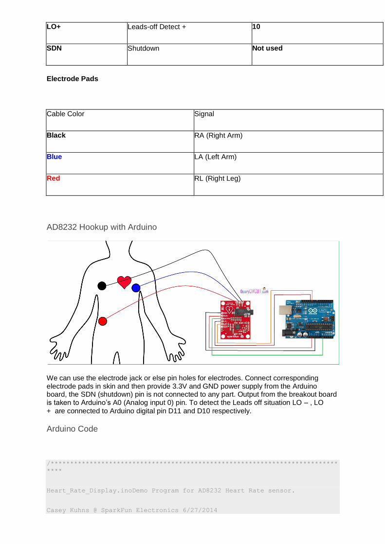
LO+ Leads-off Detect + 10
SDN Shutdown Not used
Electrode Pads
Cable Color Signal
Black RA (Right Arm)
Blue LA (Left Arm)
Red RL (Right Leg)
AD8232 Hookup with Arduino
We can use the electrode jack or else pin holes for electrodes. Connect corresponding electrode pads in skin and then provide 3.3V and GND power supply from the Arduino board, the SDN (shutdown) pin is not connected to any part. Output from the breakout board is taken to Arduino’s A0 (Analog input 0) pin. To detect the Leads off situation LO – , LO
+ are connected to Arduino digital pin D11 and D10 respectively.
Arduino Code
/**************************************************************************
****
Heart_Rate_Display.inoDemo Program for AD8232 Heart Rate sensor.
Casey Kuhns @ SparkFun Electronics 6/27/2014
https://github.com/sparkfun/AD8232_Heart_Rate_Monitor
***************************************************************************
***/
void setup() {
// initialize the serial communication:
Serial.begin(9600);
pinMode(10, INPUT); // Setup for leads off detection LO +
pinMode(11, INPUT); // Setup for leads off detection LO -
}
void loop() {
if((digitalRead(10) == 1)||(digitalRead(11) == 1)){
Serial.println('!');
}
else{
// send the value of analog input 0:
Serial.println(analogRead(A0));
}
//Wait for a bit to keep serial data from saturating
delay(1);
}
Processing Code
/**************************************************************************
****
Heart_Rate_Display.inoDemo Program for AD8232 Heart Rate sensor.
Casey Kuhns @ SparkFun Electronics 6/27/2014
https://github.com/sparkfun/AD8232_Heart_Rate_Monitor
***************************************************************************
***/
import processing.serial.*;
Serial myPort; // The serial port
int xPos = 1; // horizontal position of the graph
float height_old = 0;
float height_new = 0;
float inByte = 0;
void setup () {
// set the window size:
size(1000, 400);
// List all the available serial ports
println(Serial.list());
// Open whatever port is the one you're using.
myPort = new Serial(this, Serial.list()[0], 9600);
// don't generate a serialEvent() unless you get a newline character:
myPort.bufferUntil('\n');
// set inital background:
background(0xff);
}
void draw () {
// everything happens in the serialEvent()
}
void serialEvent (Serial myPort) {
// get the ASCII string:
String inString = myPort.readStringUntil('\n');
if (inString != null) {
// trim off any whitespace:
inString = trim(inString);
// If leads off detection is true notify with blue line
if (inString.equals("!")) {
stroke(0, 0, 0xff); //Set stroke to blue ( R, G, B)
inByte = 512; // middle of the ADC range (Flat Line)
}
// If the data is good let it through
else {

stroke(0xff, 0, 0); //Set stroke to red ( R, G, B)
inByte = float(inString);
}
//Map and draw the line for new data point
inByte = map(inByte, 0, 1023, 0, height);
height_new = height - inByte;
line(xPos - 1, height_old, xPos, height_new);
height_old = height_new;
// at the edge of the screen, go back to the beginning:
if (xPos >= width) {
xPos = 0;
background(0xff);
}
else {
// increment the horizontal position:
xPos++;
}
}
}
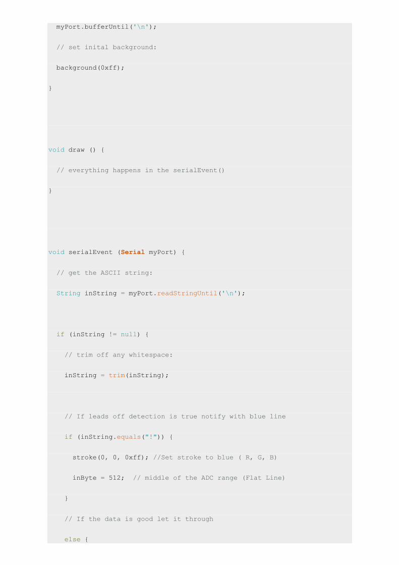
How to use Processing IDE to Plot Graph?
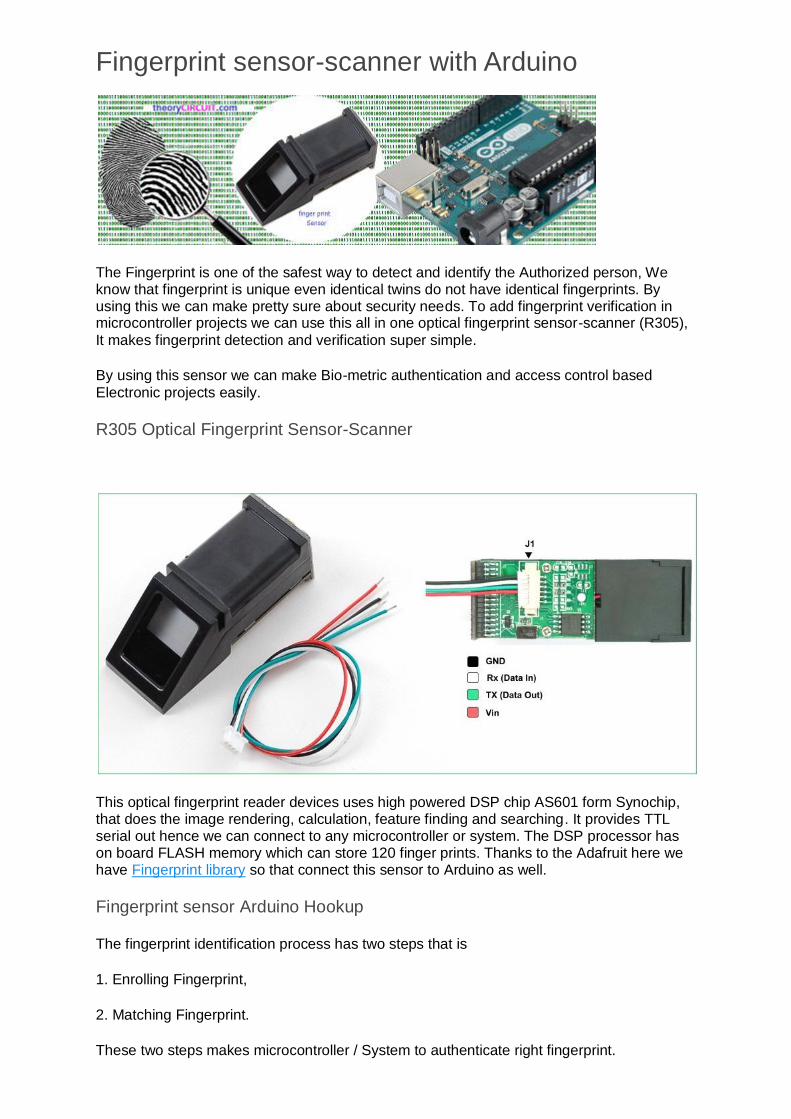
Fingerprint sensor-scanner with Arduino
The Fingerprint is one of the safest way to detect and identify the Authorized person, We know that fingerprint is unique even identical twins do not have identical fingerprints. By using this we can make pretty sure about security needs. To add fingerprint verification in microcontroller projects we can use this all in one optical fingerprint sensor-scanner (R305),
It makes fingerprint detection and verification super simple.
By using this sensor we can make Bio-metric authentication and access control based
Electronic projects easily.
R305 Optical Fingerprint Sensor-Scanner
This optical fingerprint reader devices uses high powered DSP chip AS601 form Synochip, that does the image rendering, calculation, feature finding and searching. It provides TTL serial out hence we can connect to any microcontroller or system. The DSP processor has on board FLASH memory which can store 120 finger prints. Thanks to the Adafruit here we have Fingerprint library so that connect this sensor to Arduino as well.
Fingerprint sensor Arduino Hookup
The fingerprint identification process has two steps that is
1. Enrolling Fingerprint,
2. Matching Fingerprint.
These two steps makes microcontroller / System to authenticate right fingerprint.

To use this sensor with Computer
(Only windows operating system)
Image credit: adafruit.com
Connect the white wire from the sensor to Arduino D0 pin and green wire to Arduino D1 pin. Put red & black in (+5V & GND) respectively. After the wiring over upload the following
sketch to Arduino board.
Arduino Code
// this sketch will allow you to bypass the Atmega chip
// and connect the fingerprint sensor directly to the USB/Serial
// chip converter.
// Red connects to +5V
// Black connects to Ground
// White goes to Digital 0
// Green goes to Digital 1
void setup() {}
void loop() {}
The “blank” sketch won’t work for ATmega32u4-based Arduinos hence use the following
sketch
Arduino Code for (ATmega32u4)
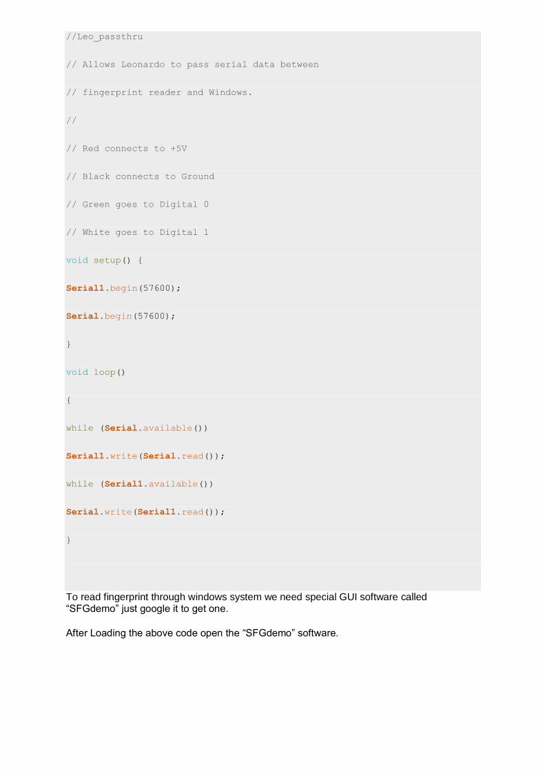
//Leo_passthru
// Allows Leonardo to pass serial data between
// fingerprint reader and Windows.
//
// Red connects to +5V
// Black connects to Ground
// Green goes to Digital 0
// White goes to Digital 1
void setup() {
Serial1.begin(57600);
Serial.begin(57600);
}
void loop()
{
while (Serial.available())
Serial1.write(Serial.read());
while (Serial1.available())
Serial.write(Serial1.read());
}
To read fingerprint through windows system we need special GUI software called “SFGdemo” just google it to get one.
After Loading the above code open the “SFGdemo” software.

Screenshot
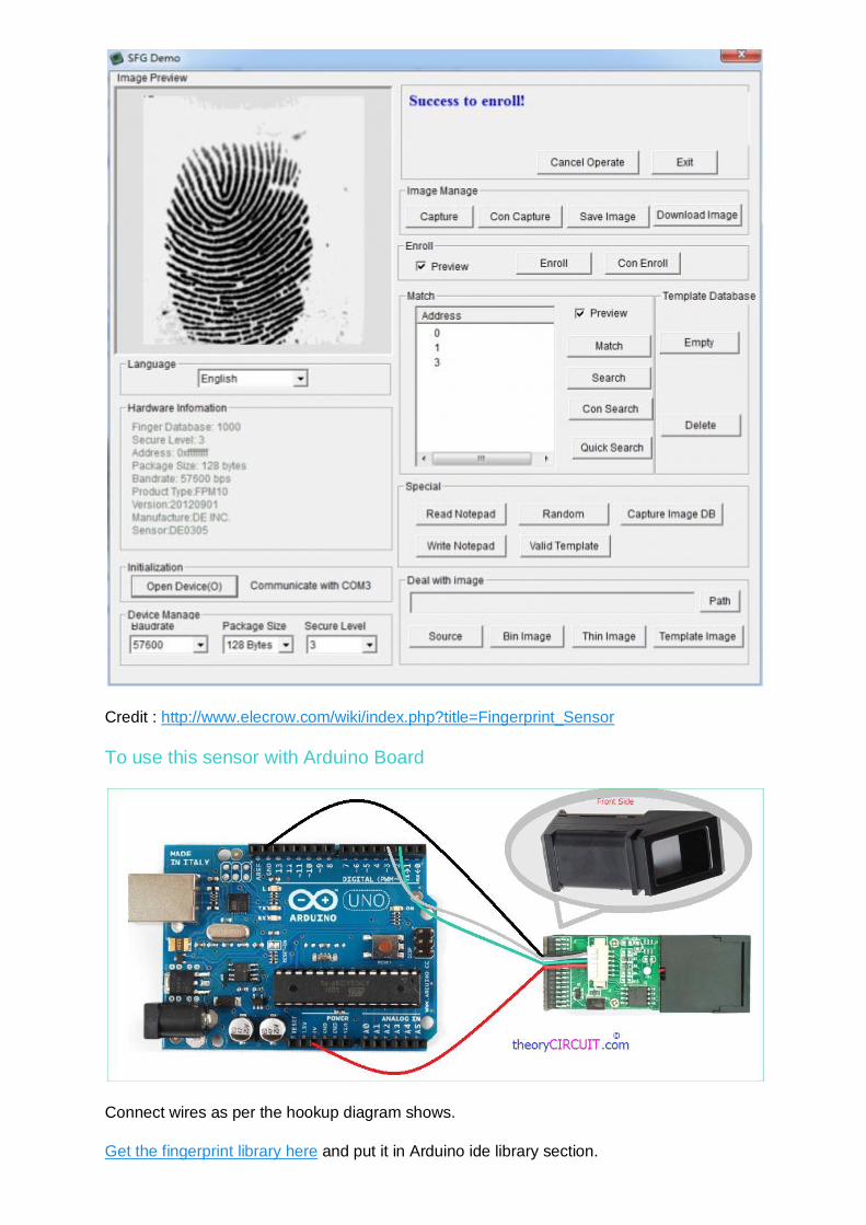
Credit : http://www.elecrow.com/wiki/index.php?title=Fingerprint_Sensor
To use this sensor with Arduino Board
Connect wires as per the hookup diagram shows.
Get the fingerprint library here and put it in Arduino ide library section.

Open the code directly by the path in Arduino IDE: File -> Example ->Adafruit_Fingerprint→enroll
Code to Enrolling with Arduino
#include <Adafruit_Fingerprint.h>
#include <SoftwareSerial.h>
uint8_t getFingerprintEnroll(int id);
// pin #2 is IN from sensor (GREEN wire)
// pin #3 is OUT from arduino (WHITE wire)
SoftwareSerial mySerial(2, 3);
Adafruit_Fingerprint finger = Adafruit_Fingerprint(&mySerial);
void setup()
{
Serial.begin(9600);
Serial.println("fingertest");
// set the data rate for the sensor serial port
finger.begin(57600);
if (finger.verifyPassword()) {
Serial.println("Found fingerprint sensor!");
} else {
Serial.println("Did not find fingerprint sensor :(");
while (1);
}
}
void loop() // run over and over again
{
Serial.println("Type in the ID # you want to save this finger as...");
int id = 0;
while (true) {
while (! Serial.available());
char c = Serial.read();
if (! isdigit(c)) break;
id *= 10;
id += c - '0';
}
Serial.print("Enrolling ID #");
Serial.println(id);
while (! getFingerprintEnroll(id) );
}
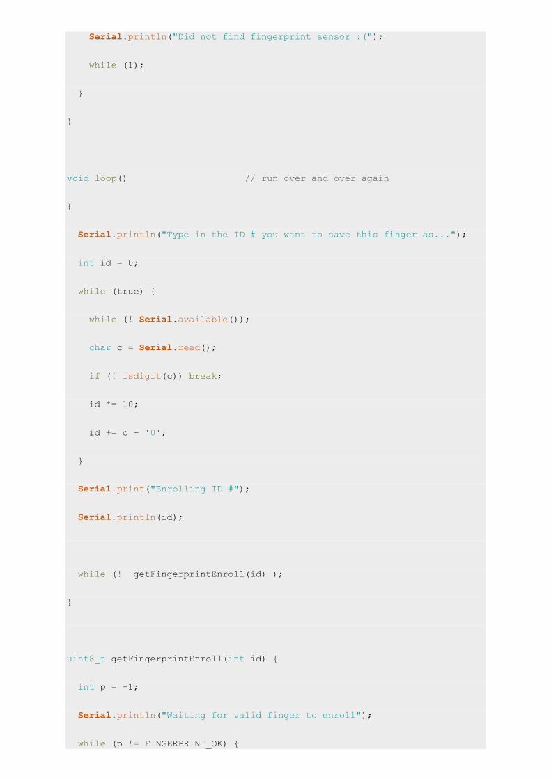
uint8_t getFingerprintEnroll(int id) {
int p = -1;
Serial.println("Waiting for valid finger to enroll");
while (p != FINGERPRINT_OK) {

p = finger.getImage();
switch (p) {
case FINGERPRINT_OK:
Serial.println("Image taken");
break;
case FINGERPRINT_NOFINGER:
Serial.println(".");
break;
case FINGERPRINT_PACKETRECIEVEERR:
Serial.println("Communication error");
break;
case FINGERPRINT_IMAGEFAIL:
Serial.println("Imaging error");
break;
default:
Serial.println("Unknown error");
break;
}
}
// OK success!
p = finger.image2Tz(1);
switch (p) {
case FINGERPRINT_OK:
Serial.println("Image converted");

break;
case FINGERPRINT_IMAGEMESS:
Serial.println("Image too messy");
return p;
case FINGERPRINT_PACKETRECIEVEERR:
Serial.println("Communication error");
return p;
case FINGERPRINT_FEATUREFAIL:
Serial.println("Could not find fingerprint features");
return p;
case FINGERPRINT_INVALIDIMAGE:
Serial.println("Could not find fingerprint features");
return p;
default:
Serial.println("Unknown error");
return p;
}
Serial.println("Remove finger");
delay(2000);
p = 0;
while (p != FINGERPRINT_NOFINGER) {
p = finger.getImage();
}
p = -1;

Serial.println("Place same finger again");
while (p != FINGERPRINT_OK) {
p = finger.getImage();
switch (p) {
case FINGERPRINT_OK:
Serial.println("Image taken");
break;
case FINGERPRINT_NOFINGER:
Serial.print(".");
break;
case FINGERPRINT_PACKETRECIEVEERR:
Serial.println("Communication error");
break;
case FINGERPRINT_IMAGEFAIL:
Serial.println("Imaging error");
break;
default:
Serial.println("Unknown error");
break;
}
}
// OK success!
p = finger.image2Tz(2);
switch (p) {
case FINGERPRINT_OK:
Serial.println("Image converted");
break;
case FINGERPRINT_IMAGEMESS:
Serial.println("Image too messy");
return p;
case FINGERPRINT_PACKETRECIEVEERR:
Serial.println("Communication error");
return p;
case FINGERPRINT_FEATUREFAIL:
Serial.println("Could not find fingerprint features");
return p;
case FINGERPRINT_INVALIDIMAGE:
Serial.println("Could not find fingerprint features");
return p;
default:
Serial.println("Unknown error");
return p;
}
// OK converted!
p = finger.createModel();
if (p == FINGERPRINT_OK) {
Serial.println("Prints matched!");
} else if (p == FINGERPRINT_PACKETRECIEVEERR) {

Serial.println("Communication error");
return p;
} else if (p == FINGERPRINT_ENROLLMISMATCH) {
Serial.println("Fingerprints did not match");
return p;
} else {
Serial.println("Unknown error");
return p;
}
Serial.print("ID "); Serial.println(id);
p = finger.storeModel(id);
if (p == FINGERPRINT_OK) {
Serial.println("Stored!");
} else if (p == FINGERPRINT_PACKETRECIEVEERR) {
Serial.println("Communication error");
return p;
} else if (p == FINGERPRINT_BADLOCATION) {
Serial.println("Could not store in that location");
return p;
} else if (p == FINGERPRINT_FLASHERR) {
Serial.println("Error writing to flash");
return p;
} else {
Serial.println("Unknown error");
return p;
}
}
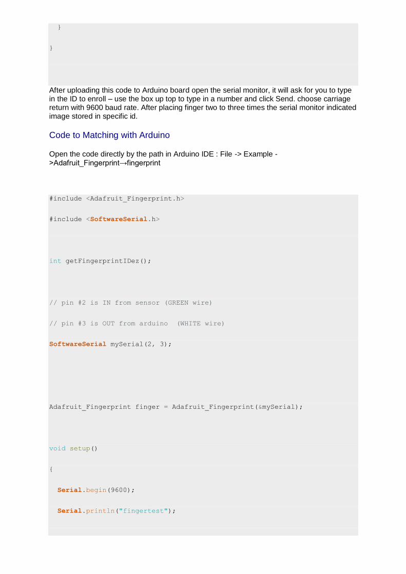
After uploading this code to Arduino board open the serial monitor, it will ask for you to type in the ID to enroll – use the box up top to type in a number and click Send. choose carriage return with 9600 baud rate. After placing finger two to three times the serial monitor indicated image stored in specific id.
Code to Matching with Arduino
Open the code directly by the path in Arduino IDE : File -> Example -
>Adafruit_Fingerprint→fingerprint
#include <Adafruit_Fingerprint.h>
#include <SoftwareSerial.h>
int getFingerprintIDez();
// pin #2 is IN from sensor (GREEN wire)
// pin #3 is OUT from arduino (WHITE wire)
SoftwareSerial mySerial(2, 3);
Adafruit_Fingerprint finger = Adafruit_Fingerprint(&mySerial);
void setup()
{
Serial.begin(9600);
Serial.println("fingertest");
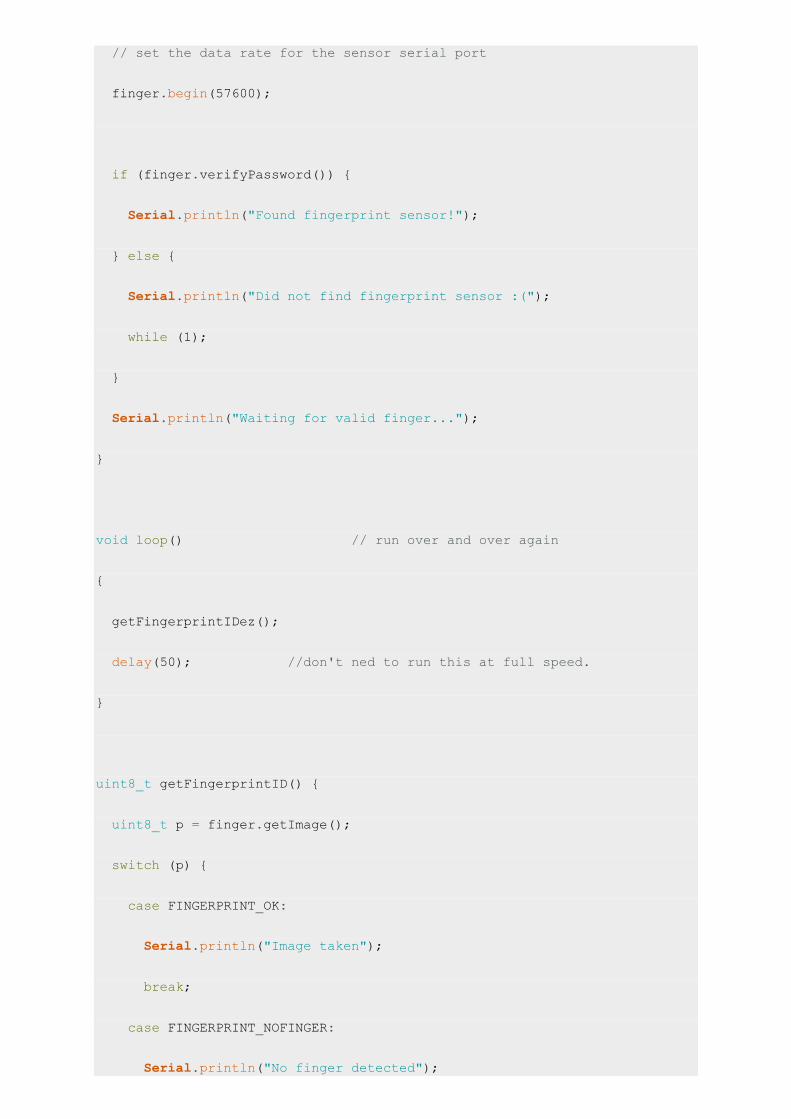
// set the data rate for the sensor serial port
finger.begin(57600);
if (finger.verifyPassword()) {
Serial.println("Found fingerprint sensor!");
} else {
Serial.println("Did not find fingerprint sensor :(");
while (1);
}
Serial.println("Waiting for valid finger...");
}
void loop() // run over and over again
{
getFingerprintIDez();
delay(50); //don't ned to run this at full speed.
}
uint8_t getFingerprintID() {
uint8_t p = finger.getImage();
switch (p) {
case FINGERPRINT_OK:
Serial.println("Image taken");
break;
case FINGERPRINT_NOFINGER:
Serial.println("No finger detected");

return p;
case FINGERPRINT_PACKETRECIEVEERR:
Serial.println("Communication error");
return p;
case FINGERPRINT_IMAGEFAIL:
Serial.println("Imaging error");
return p;
default:
Serial.println("Unknown error");
return p;
}
// OK success!
p = finger.image2Tz();
switch (p) {
case FINGERPRINT_OK:
Serial.println("Image converted");
break;
case FINGERPRINT_IMAGEMESS:
Serial.println("Image too messy");
return p;
case FINGERPRINT_PACKETRECIEVEERR:
Serial.println("Communication error");
return p;
case FINGERPRINT_FEATUREFAIL:
Serial.println("Could not find fingerprint features");
return p;
case FINGERPRINT_INVALIDIMAGE:
Serial.println("Could not find fingerprint features");
return p;
default:
Serial.println("Unknown error");
return p;
}
// OK converted!
p = finger.fingerFastSearch();
if (p == FINGERPRINT_OK) {
Serial.println("Found a print match!");
} else if (p == FINGERPRINT_PACKETRECIEVEERR) {
Serial.println("Communication error");
return p;
} else if (p == FINGERPRINT_NOTFOUND) {
Serial.println("Did not find a match");
return p;
} else {
Serial.println("Unknown error");
return p;
}
// found a match!
Serial.print("Found ID #"); Serial.print(finger.fingerID);
Serial.print(" with confidence of "); Serial.println(finger.confidence);
}
// returns -1 if failed, otherwise returns ID #
int getFingerprintIDez() {
uint8_t p = finger.getImage();
if (p != FINGERPRINT_OK) return -1;
p = finger.image2Tz();
if (p != FINGERPRINT_OK) return -1;
p = finger.fingerFastSearch();
if (p != FINGERPRINT_OK) return -1;
// found a match!
Serial.print("Found ID #"); Serial.print(finger.fingerID);
Serial.print(" with confidence of "); Serial.println(finger.confidence);
return finger.fingerID;
}
After Upload the Code,Open up the serial monitor at 9600 baud rate and when prompted place your finger against the sensor that was already enrolled. It shows found Id with number If it is the stored fingerprint.
Tutorial inspiration
http://www.elecrow.com/wiki/index.php?title=Fingerprint_Sensor
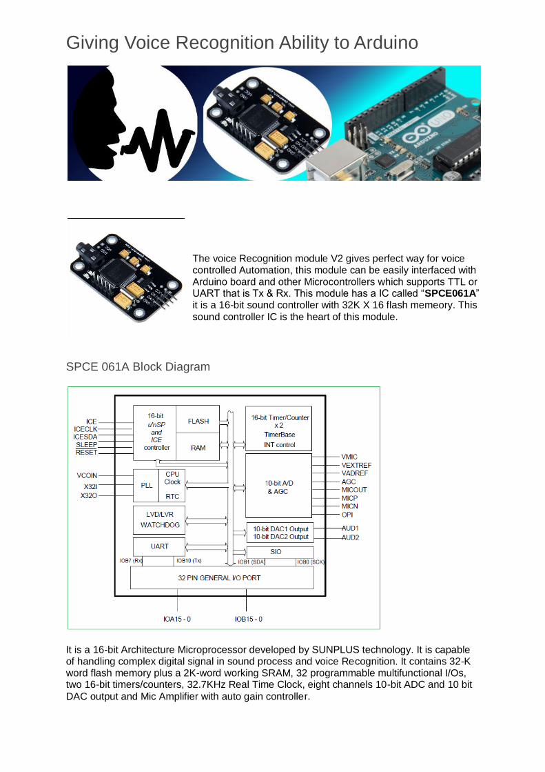
Giving Voice Recognition Ability to Arduino
The voice Recognition module V2 gives perfect way for voice controlled Automation, this module can be easily interfaced with Arduino board and other Microcontrollers which supports TTL or UART that is Tx & Rx. This module has a IC called “SPCE061A” it is a 16-bit sound controller with 32K X 16 flash memeory. This
sound controller IC is the heart of this module.
SPCE 061A Block Diagram
It is a 16-bit Architecture Microprocessor developed by SUNPLUS technology. It is capable of handling complex digital signal in sound process and voice Recognition. It contains 32-K word flash memory plus a 2K-word working SRAM, 32 programmable multifunctional I/Os, two 16-bit timers/counters, 32.7KHz Real Time Clock, eight channels 10-bit ADC and 10 bit
DAC output and Mic Amplifier with auto gain controller.

Voice Recognition Module V2
It can store 15 voice instructions in 3 groups with 5 voice instructions in one group. It has two power supply pins Vcc & Gnd and consumes 4.5 V to 5.5 Volt with less than 40mA current. The Tx & Rx pins makes UART communication possible to microcontrollers.
We cannot directly plug and play this module with Arduino or any other microcontrollers to
get Voice Recognition ability follow these steps.
1. Recording Voices 2. Making Hardware connections
3. Uploading Code
Recording Voices
Initially the module don’t know who you are? so we need to teach them and make our voice
as familiar one.
Connect the module with UART to USB converter and Interface with computer make sure
the following connections.
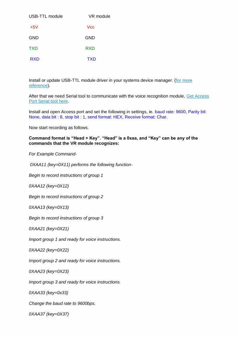
USB-TTL module VR module
+5V Vcc
GND GND
TXD RXD
RXD TXD
Install or update USB-TTL module driver in your systems device manager. (for more
reference).
After that we need Serial tool to communicate with the voice recognition module, Get Access Port Serial tool here.
Install and open Access port and set the following in settings, ie. baud rate: 9600, Parity bit:
None, data bit : 8, stop bit : 1, send format: HEX, Receive format: Char.
Now start recording as follows.
Command format is “Head + Key”. “Head” is a 0xaa, and “Key” can be any of the
commands that the VR module recognizes:
For Example Command-
0XAA11 (key=0X11) performs the following function-
Begin to record instructions of group 1
0XAA12 (key=0X12)
Begin to record instructions of group 2
0XAA13 (key=0X13)
Begin to record instructions of group 3
0XAA21 (key=0X21)
Import group 1 and ready for voice instructions.
0XAA22 (key=0X22)
Import group 2 and ready for voice instructions.
0XAA23 (key=0X23)
Import group 3 and ready for voice instructions.
0XAA33 (key=0x33)
Change the baud rate to 9600bps.
0XAA37 (key=0X37)

Switch to compact mode.
0XAA01 (key=0X01)
Delete the instructions of group 1.
0XAA02 (key=0X02)
Delete the instructions of group 2.
0XAA03 (key=0X03)
Delete the instructions of group 3.
0XAA04 (key=0X04)
Delete the instructions of all the three groups.
0XAA70 (key=0X70)
Reset serial port to 9600 baud rate, 8 data bits, no parity, 1 stop bit.
————————————————————————————————
Send: 0xaa11
Receive (in Common Mode):
START
No voice // I did not make any sound. So it replied such message
START
Speak now
Again
START
Speak again now
Different // I spoke another words for the second time. So it replied such message
START
Speak now
Again
START
Speak again now
Finish one // recording one instruction successfully
START

Again
START
Finish one
START
Again
START
Finish one
START
Again
START
Finish one
START
Again
START
Finish one
Group1 finished! // recording group 1 successfully
Now group 1 training is done and similarly you can train other groups.
Please record the following voice instrctions in order :
1.WHITE 2.RED 3.GREEN 4.BLUE
5.OFF
Then send command 0xAA21 to import group 1. Remove the voice recognition module after
successful recording with command hex code.
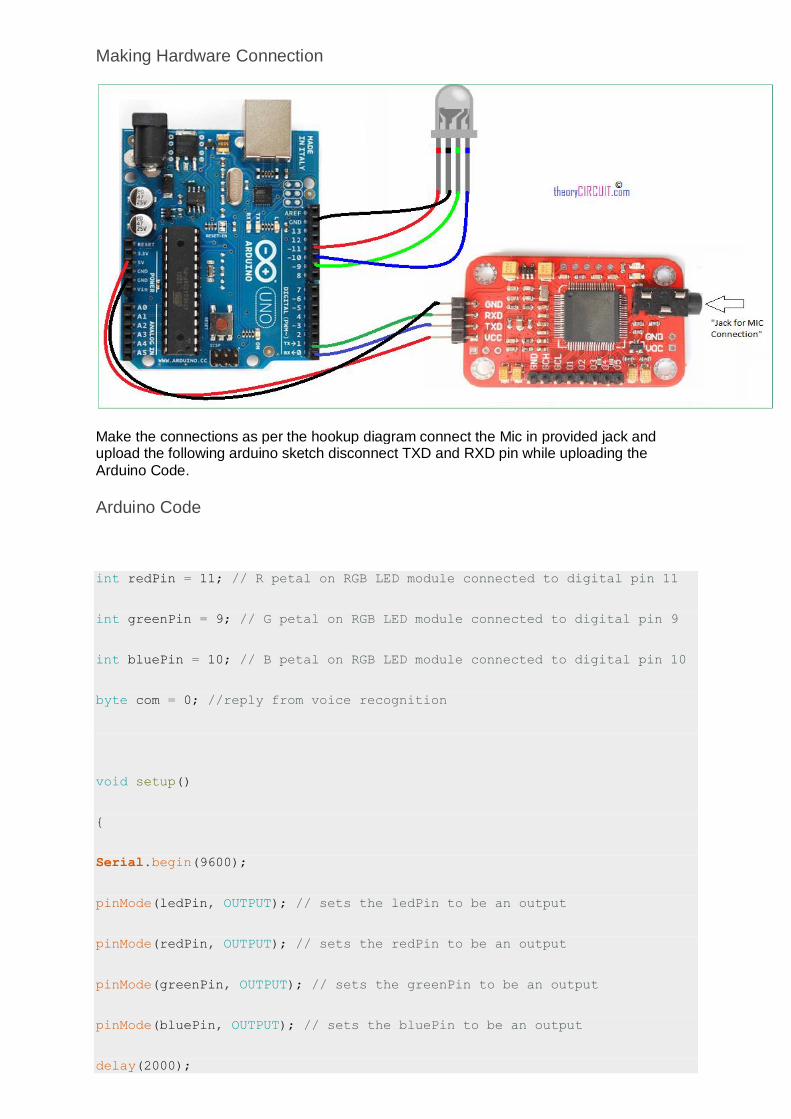
Making Hardware Connection
Make the connections as per the hookup diagram connect the Mic in provided jack and upload the following arduino sketch disconnect TXD and RXD pin while uploading the
Arduino Code.
Arduino Code
int redPin = 11; // R petal on RGB LED module connected to digital pin 11
int greenPin = 9; // G petal on RGB LED module connected to digital pin 9
int bluePin = 10; // B petal on RGB LED module connected to digital pin 10
byte com = 0; //reply from voice recognition
void setup()
{
Serial.begin(9600);
pinMode(ledPin, OUTPUT); // sets the ledPin to be an output
pinMode(redPin, OUTPUT); // sets the redPin to be an output
pinMode(greenPin, OUTPUT); // sets the greenPin to be an output
pinMode(bluePin, OUTPUT); // sets the bluePin to be an output
delay(2000);

Serial.write(0xAA);
Serial.write(0x37);
delay(1000);
Serial.write(0xAA);
Serial.write(0x21);
}
void loop() // run over and over again
{
while(Serial.available())
{
com = Serial.read();
switch(com)
{
case 0x11:
color(255,255,255); // turn RGB LED on -- white
break;
case 0x12:
color(255, 0, 0); // turn the RGB LED red
break;
case 0x13:
color(0,255, 0); // turn the RGB LED green
break;
case 0x14:
color(0, 0, 255); // turn the RGB LED blue
break;
case 0x15:
color(0,0,0); // turn the RGB LED off
break;
}
}
}
void color (unsigned char red, unsigned char green, unsigned char blue) //
the color generating function
{
analogWrite(redPin, red*102/255);
analogWrite(bluePin, blue*173/255);
analogWrite(greenPin, green*173/255);
}
DataSheet of SPCE061A
Soil Moisture Sensor and Arduino
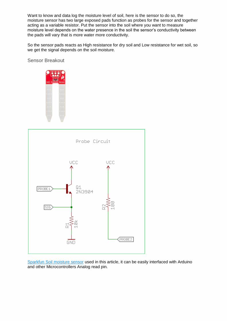
Want to know and data log the moisture level of soil, here is the sensor to do so, the moisture sensor has two large exposed pads function as probes for the sensor and together acting as a variable resistor. Put the sensor into the soil where you want to measure moisture level depends on the water presence in the soil the sensor’s conductivity between
the pads will vary that is more water more conductivity.
So the sensor pads reacts as High resistance for dry soil and Low resistance for wet soil, so we get the signal depends on the soil moisture.
Sensor Breakout
Sparkfun Soil moisture sensor used in this article, it can be easily interfaced with Arduino and other Microcontrollers Analog read pin.
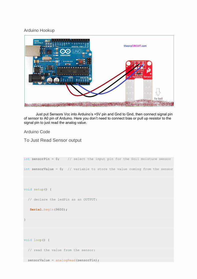
Arduino Hookup
Just put Sensors Vcc into Arduino’s +5V pin and Gnd to Gnd, then connect signal pin of sensor to A0 pin of Arduino. Here you don’t need to connect bias or pull up resistor to the
signal pin to just read the analog value.
Arduino Code
To Just Read Sensor output
int sensorPin = 0; // select the input pin for the Soil moisture sensor
int sensorValue = 0; // variable to store the value coming from the sensor
void setup() {
// declare the ledPin as an OUTPUT:
Serial.begin(9600);
}
void loop() {
// read the value from the sensor:
sensorValue = analogRead(sensorPin);

delay(1000);
Serial.print("sensor = " );
Serial.println(sensorValue);
}
Read Sensor Value for a While
The sensor pads gets corrosion when the current continuously passed through the sensor. Here is the code to take reading at particular
time for data logging.
Before that make the given circuit between Arduino board and Soil moisture sensor. Here the SL100 (NPN) transistor acts as a switch to control the supply to Sensor. When the D10 pin of Arduino goes high the sensor will get power supply if the D10 goes low the sensor disconnected from the power supply.
Code
int sensorPin = 0; // select the input pin for the Soil moisture sensor
int sensorValue = 0; // variable to store the value coming from the sensor
int sensorVCC = 10;
void setup() {
// declare the ledPin as an OUTPUT:
Serial.begin(9600);
pinMode(sensorVCC, OUTPUT);
digitalWrite(sensorVCC, LOW);

}
void loop() {
// power the sensor
digitalWrite(sensorVCC, HIGH);
delay(100); //make sure the sensor is powered
// read the value from the sensor:
sensorValue = analogRead(sensorPin);
//stop power
digitalWrite(sensorVCC, LOW);
//wait
delay(60*1000);//delay time change according to your need
Serial.print("sensor = " );
Serial.println(sensorValue);
}
Value Range
0 ~ 300 : Dry Soil
300 ~ 700 : Humid Soil
700 ~ 950 : in Water.
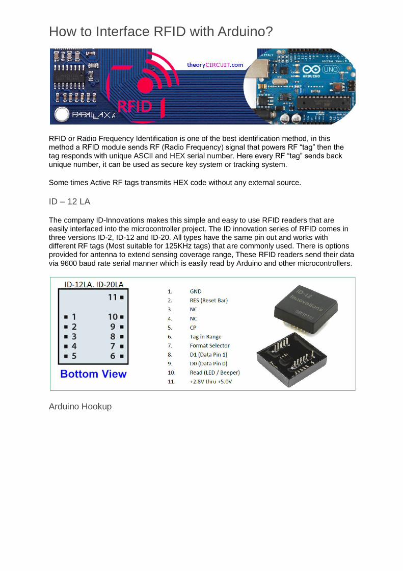
How to Interface RFID with Arduino?
RFID or Radio Frequency Identification is one of the best identification method, in this method a RFID module sends RF (Radio Frequency) signal that powers RF “tag” then the tag responds with unique ASCII and HEX serial number. Here every RF “tag” sends back unique number, it can be used as secure key system or tracking system.
Some times Active RF tags transmits HEX code without any external source.
ID – 12 LA
The company ID-Innovations makes this simple and easy to use RFID readers that are easily interfaced into the microcontroller project. The ID innovation series of RFID comes in three versions ID-2, ID-12 and ID-20. All types have the same pin out and works with different RF tags (Most suitable for 125KHz tags) that are commonly used. There is options provided for antenna to extend sensing coverage range, These RFID readers send their data
via 9600 baud rate serial manner which is easily read by Arduino and other microcontrollers.
Arduino Hookup

By the way it is very easy to connect ID 12-LA RFID reader with Arduino, but note that the pins on these readers are not spaced properly for use with bread board hence you may use sparkfun RFID breakout, the pin D0 is connected with Arduino D0/Rx pin (digital pin 0). This reader provides LED/Buzzer pin (reader pin 10) that will light/buzz when a
tag is read.
Arduino Code to Read Tag
/* RFID ID12 */
char val; // variable to store the data from the serial port
void setup() {
Serial.begin(9600); // connect to the serial port
}
void loop () {
// read the serial port
if(Serial.available() > 0) {
val = Serial.read();
Serial.print(val);
}
}
This simple Arduino code helps to read RF tag number through serial monitor.
After reading the tag code we can use that code to control Arduino pins for specific tag
controlled operations.
RFID ID-12LA Data sheet
-----------------------end of top five arduino projects from theoryCIRCUIT.com----------------------