Embed Size (px)
Citation preview
Heap Leach Facility Feasibility Design Eagle Gold Project
Prepared for:
80 Richmond St. West Suite 303 Toronto, Ontario M5H 2A4 Phone: (416) 866-8800 Fax: (416) 866-8801 Prepared by:
120 West Park Drive Grand Junction, Colorado 81505 (970) 986-3566 Fax (970) 241-3120 Tetra Tech Project No. 114-201045X
February 10, 2012
Heap Leach Facility Feasibility Design Victoria Gold
Tetra Tech February 10, 2012 i
TABLE OF CONTENTS
1.0 INTRODUCTION ............................................................................................................. 1 1.1 General ................................................................................................................ 1 1.2 Previous Studies and Supporting Documents ...................................................... 1
2.0 PROJECT DESCRIPTION .............................................................................................. 2
3.0 SITE CONDITIONS ......................................................................................................... 3 3.1 Climate ................................................................................................................ 3 3.2 Subsurface Conditions ......................................................................................... 3
3.2.1 Overburden ............................................................................................................ 4 3.2.2 Bedrock .................................................................................................................. 4 3.2.3 Groundwater .......................................................................................................... 5 3.2.4 Permafrost .............................................................................................................. 5 3.2.5 Geological Hazards ................................................................................................ 5
3.3 Hydrogeology ....................................................................................................... 5 3.4 Seismicity ............................................................................................................ 6
4.0 DESIGN CRITERIA AND APPROACH ........................................................................... 7 4.1 Permitting Considerations .................................................................................... 7 4.2 Design Requirements .......................................................................................... 7 4.3 Design Basis ........................................................................................................ 8 4.4 Engineering Design Criteria ................................................................................. 9
5.0 ENGINEERING ANALYSES ......................................................................................... 13 5.1 General .............................................................................................................. 13 5.2 Heap Leach Pad and Confining Embankment Design ........................................ 13
5.2.1 Design Criteria and Requirements ....................................................................... 13 5.2.2 Confining Embankment ........................................................................................ 14 5.2.3 In-Heap Pond ....................................................................................................... 14 5.2.4 In-Heap Pond Spillway ......................................................................................... 15
5.3 Event Ponds ...................................................................................................... 16 5.4 Liner System Design .......................................................................................... 16
5.4.1 General ................................................................................................................ 16 5.4.2 Liner Subgrade..................................................................................................... 17 5.4.3 Geomembrane Selection ..................................................................................... 17
5.5 Overliner Drain Fill ............................................................................................. 18 5.6 Solution Collection Piping .................................................................................. 18 5.7 Solution Collection Sump and Vertical Riser ...................................................... 19 5.8 Closure Outlet System ....................................................................................... 19 5.9 Slope Stability .................................................................................................... 20
5.9.1 Phreatic Conditions .............................................................................................. 20 5.9.2 Analysis Methodology .......................................................................................... 20 5.9.3 Impact of Mine Site Development of Frozen Ground Conditions ........................ 23 5.9.4 Geotechnical Stability Assessment ...................................................................... 23 5.9.5 Liquefaction .......................................................................................................... 24
Heap Leach Facility Feasibility Design Victoria Gold
Tetra Tech February 10, 2012 ii
5.10 Settlement Assessment ..................................................................................... 25 5.11 Heap Leach Facility Water Balance ................................................................... 26
5.11.1 Water Balance Model ........................................................................................... 26 5.11.2 Water Balance Model Results .............................................................................. 27
5.12 Surface Water Management of Heap Leach Pad ............................................... 31 5.13 Dublin Gulch Diversion Channel ........................................................................ 31
5.13.1 Hydrologic Design Flows ..................................................................................... 32 5.13.2 Channel Armoring ................................................................................................ 32 5.13.3 Channel Dimensions ............................................................................................ 33 5.13.4 Construction Considerations ................................................................................ 34
6.0 HEAP LEACH FACILITY CONSTRUCTION ................................................................. 35 6.1 Construction Staging .......................................................................................... 35 6.2 Foundation Preparation...................................................................................... 35
6.2.1 Foundation Improvement ..................................................................................... 35 6.2.2 Foundation Drainage ........................................................................................... 35
6.3 Dam Configuration and Zoning .......................................................................... 37 6.4 Liner System ...................................................................................................... 38 6.5 Drain Fill ............................................................................................................ 39 6.6 CQA Testing ...................................................................................................... 40 6.7 Borrow Development ......................................................................................... 40 6.8 Geotechnical Instrumentation ............................................................................ 40
7.0 HEAP LEACH OPERATIONS ....................................................................................... 42 7.1 General .............................................................................................................. 42 7.2 Cold Weather Considerations ............................................................................ 42 7.3 Solution Delivery System ................................................................................... 44
8.0 MATERIAL QUANTITIES ............................................................................................. 45
9.0 GENERAL INFORMATION ........................................................................................... 46 9.1 Applicability ........................................................................................................ 46 9.2 Acknowledgement of Key Internal Participants .................................................. 46 9.3 Quality Statement and Affirmation of Limitations ................................................ 46
10.0 REFERENCES .............................................................................................................. 47
Heap Leach Facility Feasibility Design Victoria Gold
Tetra Tech February 10, 2012 iii
LIST OF TABLES
Table 3.1: Probabilistic Ground Motions for Dublin Gulch NRCAN 2005 National Building Code of Canada Seismic Hazard Interpolation ..................................................................................... 6 Table 4.1: Summary of Design Requirements ............................................................................ 7 Table 4.2: Engineering Design Criteria ........................................................................................ 9 Table 5.1: In-Heap Pond Volume Requirements Summary ....................................................... 15 Table 5.2 Mechanical Properties of Site Construction Materials ................................................ 22 Table 5.3 Embankment Stability Analysis Results for Various Materials.................................... 24 Table 5.4: Total Freshwater Volume Requirements .................................................................. 31 Table 5.5: Dublin Gulch Diversion Channel Design Flows ......................................................... 32 Table 5.6: Dublin Gulch Diversion Channel Summary ............................................................... 33 Table 6.1: Foundation Preparation and Underdrains ................................................................. 36 Table 6.2: Dam Configuration and Zoning ................................................................................. 38 Table 6.3: Heap Leach Facility Liner System ............................................................................ 39 Table 6.4: Overliner System ...................................................................................................... 40 Table 7.1: Recorded Minimum Air Temperature Comparison .................................................... 43
LIST OF ILLUSTRATIONS
Illustration 5.1 Ann Gulch Heap Leach Pad General Arrangement with Embankment Analysis Locations ……………………………………………………………………………………………… 25 Illustration 5.2 Embankment Stability Analysis Section 1-8 ………………………………………..26 Illustration 5.3 Embankment Stability Analysis Section 1-11………………………………..……. 26 Illustration 5.4: Heap Leach Facility Water Balance Model Schematic …………………………..31 Illustration 5.5: Phase 1 Freshwater Make-up Requirements ……………………………………..32 Illustration 5.6: Phase 2 Freshwater Make-up Requirements ……………………………………..33 Illustration 5.7: Phase 3 Freshwater Make-up Requirements ..……………………………………34
LIST OF APPENDICES
Appendix A Figures
Figure 1 Location Map Figure 2 General Facilities Arrangement Figure 3 Heap Leach Pad Grading & Temporary Diversion Channels Figure 4 Heap Leach Pad Sections Figure 5 Heap Leach Pad Details Figure 6 Underdrain Pipes Layout Figure 7 Heap Confining Embankment Plan & Section Figure 8 PLS Sump Details Figure 9 Diversion Channel Embankment Plan & Section Figure 10 Drain Pipe Layout Figure 11 Drain Pipe Details Figure 12 Drain Pipe Details Figure 13 Spillway Plan & Profile Figure 14 Spillway Sections & Details Figure 15 Event Pond Layouts

Heap Leach Facility Feasibility Design Victoria Gold
Tetra Tech February 10, 2012 iv
Figure 16 Event Pond Sections Figure 17 Dublin Gulch Diversion Channel Plan & Profile Figure 18 Dublin Gulch Diversion Channel Plan & Profile Figure 19 Dublin Gulch Diversion Channel Plan & Profile Figure 20 Dublin Gulch Diversion Channel Sections & Details Figure 21 Dublin Gulch Diversion Channel Sections & Details Figure 22 Ultimate Heap Pile Plan
Appendix B Supporting Information by Others
Eagle Gold Project – Dublin Gulch, Yukon – 2011 Geotechnical Investigation for Mine Site Infrastructure, Factual Data Report, Final, BGC Engineering Inc., 19 October 2011
Eagle Gold – Mine Site Infrastructure, General Earthworks Guidance, BGC Engineering Inc., 14 October 2011
Eagle Gold – Heap Leach Pad, Water Diversion and Process Management Ponds DRAFT Foundation Report, BGC Engineering Inc., 21 April 2011
Eagle Gold – Borrow Evaluation Report, BGC Engineering Inc., 21 April 2011 Eagle Gold – Geotechnical Design Basis for Mine Site Infrastructure in the Project
Proposal, BGC Engineering Inc., 11 May 2011 Report on Seismic Refraction and Downhole Seismic Investigation and Proposed Mine
Site Facilities Eagle Gold – Frontier Geosciences Inc., Sept 2011 Eagle Gold Project – Dublin Gulch, Yukon – Site Facilities Geotechnical Investigation,
Factual Data Report, Final, BGC Engineering Inc., 5 March 2010 Appendix C Tetra Tech Technical Memorandums
Eagle Gold Heap Leach Facility Water Balance, 1 February, 2012 In-Heap Pond, Spillway and Event Pond Sizing, 9 February, 2012 Dublin Gulch Diversion Channel Design, 23 December, 2011 Dublin Gulch – Seismic Peak Ground Accelerations for Design, 3 May 2011 HLP Embankment Filter Design, 28 October 2011 Eagle Gold HLF – Drain Pipe Design, 10 February 2012 Heap Leach Facility Settlement Assessment, 30 August 2011
Appendix D Technical Specifications Appendix E Summary of Construction Quantities
Heap Leach Facility Feasibility Design Victoria Gold
Tetra Tech February 10, 2012 1
1.0 INTRODUCTION
1.1 General Victoria Gold Corp. (Victoria Gold) commissioned Tetra Tech to perform a Feasibility Study (FS) on the Eagle Gold Project (Project) in the central Yukon Territory, Canada. This report presents the FS-level design for the Heap Leach Facility (HLF), used to support the FS cost estimates. Summaries of meteorology, hydrology, seismicity, geological, geotechnical, and hydrogeological conditions that were used as inputs to those designs are also presented.
Planning for the heap leach is in the feasibility stage, and therefore, the plans as currently proposed are subject to change or modification as additional information becomes available from environmental studies, engineering analyses, and input from regulatory personnel and interested parties.
1.2 Previous Studies and Supporting Documents This document incorporates information from numerous sources as referenced herein. Geotechnical site investigations and recommendations are provided by BGC Engineering Inc. (BGC). Pertinent documents prepared by BGC are included in the appendices for reference.
Previous studies relevant to this report include the following:
• Victoria Gold Corp. – Pre-Feasibility Study on the Eagle Gold Project, Yukon Territory, Canada, Scott Wilson Roscoe Postle Associates, Inc. July 16, 2010.
• Technical Report on the Eagle Gold Project, Yukon Territory, Canada, Scott Wilson Roscoe Postle Associates, Inc. April 23, 2010.
• New Millinium Mining, LTD., Dublin Gulch Project, Rescan Engineering, February 1997.
• First Dynasty Mines, LTD., Dublin Gulch Project, Report on Feasibility of the Heap Leach Pad and Associated Structures, Knight Piesold, February 1996.
Heap Leach Facility Feasibility Design Victoria Gold
Tetra Tech February 10, 2012 2
2.0 PROJECT DESCRIPTION
The Eagle Gold Site is in the center of the Yukon Territory about 350 kilometers north of the capital, Whitehorse, and approximately 45 kilometers north of Mayo, a small village on the Stewart River. The proposed project site is located within the lower Dublin Gulch/Eagle Creek watershed (Figure 1).
The proposed Heap Leach Facility (HLF) is located approximately 1.2 km north of the Eagle Zone orebody. The majority of the HLF is located in the Ann Gulch catchment, a small ephemeral tributary to Dublin Gulch. The base of the HLF is in the valley floor of Dublin Gulch at an elevation of 840 masl, and at full height the HLF extends up Ann Gulch to an elevation of 1,080 masl. Facilities specific to the Heap Leach Facility Design can be seen in Figure 2.
The HLF comprises a number of elements: a rock-filled embankment to provide stability to the base of the HLF, a lined storage area for the ore to be leached, an in-heap storage pond to contain the pregnant solution, pumping wells for the extraction of solution, ponds to contain excess solution in extreme events, diversions, and leak detection, recovery and monitoring systems to ensure the containment of solution. An associated facility is the diversion structure and channel to relocate the Dublin Gulch waterway around the HLF. Engineering of these components is discussed in the following sections and design figures are presented in Appendix A. Pertinent supporting documentation by others is included in Appendix B and engineering calculations are presented in Appendix C. Material take off quantities to support capital and operating costs have been prepared and are included in Section 8.
Heap Leach Facility Feasibility Design Victoria Gold
Tetra Tech February 10, 2012 3
3.0 SITE CONDITIONS
A detailed description of the HLF site is provided in a report titled Eagle Gold – Heap Leach Pad, Water Diversion and Process Management Ponds DRAFT Foundation Report issued by BGC and dated 21 April 2011 (included as Appendix B) and is summarized below.
The site topography involves moderate to high relief, with ground elevation varying from approximately 800 to 1400 masl. Ground conditions can vary considerably across the site. Further, due to poor drill recovery and the evolution of the field investigation program to match the evolving general arrangement, there is limited information and significant uncertainty in the subsurface conditions at certain areas of the site.
Groundwater was observed at varying depths across the site, generally close to the elevation of streams in the valley bottoms (i.e. less than 2 to 3 m below grade), and often below the depth of test pit excavation (i.e. often 5 to 6 m depth) on the hillsides.
3.1 Climate The property lies within the Mayo Lake–Ross River Eco-region in central Yukon. The area is characterized by a “continental” type climate, with moderate annual precipitation and a large temperature range. Summers are short and can be hot, while winters are long and cold with moderate snowfall. Rainstorm events can occur frequently during the summer, and may contribute 30% to 40% of the annual precipitation. Higher elevations are snow-free by mid-June.
Frost action may occur at any time during the summer or fall. Climate monitoring began at Potato Hills station (located in the upper Dublin Gulch watershed) in August 2007 and at the Camp station (located close to the existing exploration camp) in August 2009. Both stations are still in operation.Regional climate data was collected from up to nine stations throughout the Yukon Territory.
The mean annual temperature for the area is approximately -3°C, with an annual range of 63.5°C for the period of record. The estimated mean annual precipitation in the study area ranges from 350 mm to over 600 mm. This range in annual estimated precipitation reflects the elevation changes at the site.
This climate description has been summarized from Stantec, 2011 Environmental Baseline Report: Climate.
3.2 Subsurface Conditions Today’s geologic conditions at the Dublin Gulch site have been strongly influenced by the geotectonic forces that produced the Eagle Zone deposit. The folding, faulting and plutonic activities have resulted in relatively weak rock mass with relatively poor mechanical properties. Further with frost fracturing and permafrost common at the latitude of the project site, shallow subsurface processes and rock/soil characteristics are more complex.
Overburden soils encountered on the sloping ground at the mine site typically consist of a veneer of organic soils overlying a blanket of colluvium, which overlies weathered bedrock.
Glacial till is generally only encountered on the lower flanks of the north and west-facing slopes located north and west of the proposed open pit, above Dublin Gulch and Haggart Creek. The till is often overlain by colluvium. Placer tailings (fill) cover most of the valley bottom of Dublin Gulch and Haggart Creek. Alluvial soils are occasionally encountered along undisturbed valley-bottom areas.
Heap Leach Facility Feasibility Design Victoria Gold
Tetra Tech February 10, 2012 4
The bedrock encountered in the mine site area is generally classified as metamorphosed sedimentary rock, with a variably deep weathering profile. The intact rock strength of the encountered rock types is highly variable, with strength ranging between R0 class (i.e. corresponding to < 1 MPa Unconfined Compressive Strength, UCS) and R4 (50-100 MPa UCS). The average intact strength is estimated to be approximately R2 (5-25 MPa) in the metasedimentary rock, depending upon the degree of weathering, but with significant variability across the site.
3.2.1 Overburden Overburden soil conditions are distinctly different in the Dublin Gulch valley bottom from those encountered above the valley bottom in Ann Gulch and south of Dublin Gulch along the southern edge of the proposed heap. In the Uplands above the valley bottom, the upper soil unit consists of a thin horizon of organic soil, rootlets, woody debris and plant matter ranging from 0.1 to 2.7 m thickness and averaging approximately 0.3 m. The organic cover above the valley bottom overlies colluvium ranging in thickness from 0.2 to 15.2 m, and averaging approximately 2.9 m. The colluvium consists of loose to compact angular gravel with occasional cobbles in a silt and sand matrix, derived from transported weathered metasedimentary bedrock. The colluvium may also include variable amounts of organics, which are often observed in distinct layers within the colluvium.
The overburden soils in the valley bottom have been reworked by historical placer mining activities. Placer tailings (fill) are observed from the ground surface to bedrock, with thicknesses ranging between 2.4 m and 16.5 m, and an average thickness of approximately 6.6 m. The material encountered is generally a well graded, loose to dense, silty sand and gravel, ranging to sand and gravel with some silt and occasional cobbles and boulders. Loose and moist zones have been encountered within the placer tailings. There is little to no vegetative cover on the placer tailings.
The placer tailings in the valley bottom have highly variable particle size distribution and density, and are generally saturated. Recorded Standard Penetrometer (SPT) blowcounts, N, are summarized in the BGC report (Appendix B) for the placer tailings within the footprint of the proposed process management ponds. No blowcount data are available within the footprint of the heap leach pad, but the placer tailings (fill) materials are expected to have a similar extreme variability in penetration resistance and associated strength and stiffness.
The overburden at the southern edge of the proposed HLF includes 4.4 m of placer tailings, and a variable thickness of till ranging between 1.5 m to 16.4 m. The till is a compact to dense sandy silt to silty sand with some gravel.
Seismic refraction surveys were performed to evaluate the variability of the overburden depth. Generally the thickness of the overburden transitions smoothly from very little at the top of the slopes increasing to the valley floor. This is the same trend with the depth of weathering.
3.2.2 Bedrock Bedrock was observed in the uplands above Dublin Gulch immediately below colluvium at depths ranging between 0.0 and 16.8 m below existing grade (average depth to bedrock at 3.5 m where observed). Bedrock was observed in the valley bottom at depths ranging between 1.5 and 16.5 m below existing grade, with an average depth to bedrock at 6.2 m where observed. The very limited amount of data at the southern edge of the HLF suggests that bedrock is relatively deep (i.e. greater than 8 m).
Observed bedrock consisted of highly to completely weathered metasedimentary rock (i.e.Type 3 rock) or moderately to highly weathered rock (i.e. Type 2 rock). The metasediments in general
Heap Leach Facility Feasibility Design Victoria Gold
Tetra Tech February 10, 2012 5
are observed as strongly foliated yellowish brown to dark grey phyllites interbedded with quartzites. The quartzites are variably gritty, micaceous, and massive. Phyllitic metasediments are composed of muscovite-sericite and chlorite.
The rock mass quality and characteristics have been inferred from observations in boreholes within the heap leach pad footprint. Rock Mass Rating values of 20 to 30 were determined from the observed rock core to about 10 m depth, then increased to about 45 to 50 at most locations.
The seismic refraction work confirmed the depth to bedrock to be relatively deep ranging from 5 to 15 m along the southeast limits of the HLP. The depth to moderately weathered bedrock ranged from 20 to 35 m.
3.2.3 Groundwater The observed groundwater depths on the open slopes in the upper Ann Gulch valley range from 6.1 m below grade close to the middle of Ann Gulch to 15.4 m in the headwaters of Ann Gulch. Water levels are typically about 2.5 m below ground surface in the Dublin Gulch valley bottom, but can be expected to be closer to ground surface near streams and deeper below piles of tailings. It is anticipated that these levels will vary seasonally.
For design purposes, it was assumed that the natural groundwater table is at approximately 10-15 m depth below grade in the uplands, and at close to the elevation of existing drainage courses in the valley bottom. However, groundwater can be expected to be encountered locally at shallower depths, specifically when approaching the main drainages. This variability should be considered in future detailed design and construction.
3.2.4 Permafrost Frozen ground was encountered in the upper part of the HLF footprint (i.e. Upland area) in various test pits. When observed in a plan view, many of the test pits are located on the eastern slope of Ann Gulch, and generally align in a NE trend, covering the entire HLF footprint, from its most eastern edge to its western end at the heap leach containment dike.
The reason for this connection between the frozen ground observations is unknown and might simply correspond to sporadic disconnected patches; nevertheless the continuity of the linear feature may deserve to be studied in more detail and accounted for during site preparation and construction. Frozen ground was typically encountered within colluvial gravels and gravels and sands with depths varying between 0.6 m to 2.8 m, and occasionally included excess ice with limited thickness.
Frozen ground was not encountered in the valley bottom nor on the southern edge of the proposed heap leach pad, but localized pockets of frozen ground may be present in these areas.
3.2.5 Geological Hazards Around the HLF site area, geological hazards as determined by Stantec (2010) mainly include permafrost processes in the west-facing slopes at the upper part of the valley and surface seepage at the bottom of the valley between the rockfill diversion berm and rockfill embankment. Some of the south-facing lower and steeper slopes above Dublin Gulch are affected by rockfall and rockslide hazards.
3.3 Hydrogeology The Eagle Gold project is located in the Dublin Gulch/Eagle Creek watershed, a northeast trending drainage that ranges in elevation from 790 m to over 1,500 m. The regional drainage
Heap Leach Facility Feasibility Design Victoria Gold
Tetra Tech February 10, 2012 6
patterns are largely controlled by the structural geologic features such as faults and folds. Near surface groundwater is recharged by precipitation and flows toward the valley floors through the alluvial/colluvial sediments and the fractured bedrock. Therefore the groundwater table mimics the topography. Surface seeps have been noted at the site; they are typically seasonal and may be structurally controlled by geologic contacts in places. Some of the larger seeps have caused surface depressions by destabilizing the soils locally.
3.4 Seismicity A seismic hazard analysis (SHA) was performed by Tetra Tech for the site. The SHA is presented in Appendix C of this report and includes results from both deterministic and probabilistic methods. Deterministic analyses were performed using five equally weighted attenuation relationships to evaluate seismic hazards for the property resulting from a maximum credible earthquake (MCE). A MCE, by definition, has no specific recurrence interval and is the largest reasonably conceivable earthquake that appears possible along a recognized fault or within a geographically defined tectonic province, under the presently known or presumed tectonic framework. Theoretically, no ground motion should occur which exceeds that of the MCE. A deterministic analysis therefore allows for a more conservative approach to the determination of risks associated with identified seismic hazards. Data published by Natural Resources Canada (NRCAN) were used in the probabilistic analysis to estimate the probability of exceedance of peak ground accelerations (PGA) at the site for various return periods.
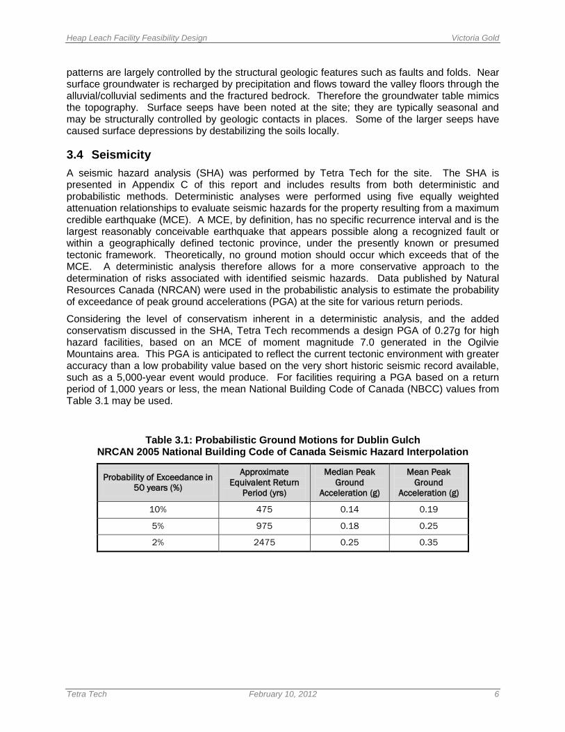
Considering the level of conservatism inherent in a deterministic analysis, and the added conservatism discussed in the SHA, Tetra Tech recommends a design PGA of 0.27g for high hazard facilities, based on an MCE of moment magnitude 7.0 generated in the Ogilvie Mountains area. This PGA is anticipated to reflect the current tectonic environment with greater accuracy than a low probability value based on the very short historic seismic record available, such as a 5,000-year event would produce. For facilities requiring a PGA based on a return period of 1,000 years or less, the mean National Building Code of Canada (NBCC) values from Table 3.1 may be used.
Table 3.1: Probabilistic Ground Motions for Dublin Gulch NRCAN 2005 National Building Code of Canada Seismic Hazard Interpolation
Probability of Exceedance in 50 years (%)
Approximate Equivalent Return
Period (yrs)
Median Peak Ground
Acceleration (g)
Mean Peak Ground
Acceleration (g)
10% 475 0.14 0.19
5% 975 0.18 0.25
2% 2475 0.25 0.35

Heap Leach Facility Feasibility Design Victoria Gold
Tetra Tech February 10, 2012 7
4.0 DESIGN CRITERIA AND APPROACH
4.1 Permitting Considerations Regulations and permitting requirements for Heap Leach Facilities in the Yukon Territory are not expressly stated; but rather, they have historically relied on regulations from other regions and on precedence established from other successful projects. Previous studies (Scott Wilson 2010) selected Brewery Creek, the gold mine (1996-2002) located approximately 55 km east of Dawson City, Canada as the example facility to follow for permitting guidelines. This was understood to be the only HLF permitted in the Yukon, the design of which (Sitka Corporation 1996) was based on the Nevada State guidelines and associated permitting limitations. This approach has been carried into the feasibility study along with best engineering practice.
The Heap Leach Facility design standards adopted for the project include:
• The regulatory requirements of Yukon and Canada;
• The Yukon Water Board Licensing Guidelines (2009);
• Guidelines from the Canadian Dam Association (2007); and
• Permitting requirements of the State of Nevada. These are not regulatory requirements in the Yukon, but are considered as standards for best practice.
4.2 Design Requirements There are currently no published international standards for the design and construction of the heap leach facility. Nevada State Guidelines provide minimum standards for heap leach facilities and have been adopted for the Project. North American standards for the design of embankment dams were used where applicable, specifically the Canadian Dam Association guidelines. Table 4.1 summarizes the main technical and permitting requirements for the State of Nevada for the key elements of the HLF design.
Table 4.1: Summary of Design Requirements
Heap Leach Feature Description
Leach Pad
System must have containment capability equal to or greater than that of a composite liner consisting of a synthetic liner over one foot of compacted soil at a permeability of 1 x 10⁻⁶ cm/s or 1 x 10⁻⁵ cm/s if a leak detection system is used beneath portions of the liner with the greatest potential for leakage Synthetic liners must be rated as having resistance to fluid passage equal to a permeability of less than or equal to 1 x 10-11 cm/s.
Solution Ponds
System must have a primary synthetic liner and a secondary liner that meet the above-described liner specifications. The synthetic liners must be separated by a fluid transmission layer which is capable of transmitting leaked fluids at a rate that will ensure that excessive head will not develop on the secondary liner
Heap Leach Facility Feasibility Design Victoria Gold
Tetra Tech February 10, 2012 8
Heap Leach Feature Description
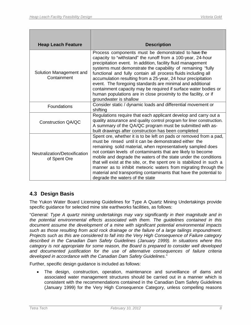
Solution Management and Containment
Process components must be demonstrated to have the capacity to “withstand” the runoff from a 100-year, 24-hour precipitation event. In addition, facility fluid management systems must demonstrate the capability of remaining “fully functional and fully contain all process fluids including all accumulation resulting from a 25-year, 24 hour precipitation event. The foregoing standards are minimal and additional containment capacity may be required if surface water bodies or human populations are in close proximity to the facility, or if groundwater is shallow
Foundations Consider static / dynamic loads and differential movement or shifting
Construction QA/QC Regulations require that each applicant develop and carry out a quality assurance and quality control program for liner construction. A summary of the QA/QC program must be submitted with as-built drawings after construction has been completed
Neutralization/Detoxification of Spent Ore
Spent ore, whether it is to be left on pads or removed from a pad, must be rinsed until it can be demonstrated either the remaining solid material, when representatively sampled does not contain levels of contaminants that are likely to become mobile and degrade the waters of the state under the conditions that will exist at the site, or, the spent ore is stabilized in such a manner as to inhibit meteoric waters from migrating through the material and transporting contaminants that have the potential to degrade the waters of the state
4.3 Design Basis The Yukon Water Board Licensing Guidelines for Type A Quartz Mining Undertakings provide specific guidance for selected mine site earthworks facilities, as follows:
“General: Type A quartz mining undertakings may vary significantly in their magnitude and in the potential environmental effects associated with them. The guidelines contained in this document assume the development of a mine with significant potential environmental impacts such as those resulting from acid rock drainage or the failure of a large tailings impoundment. Projects such as this are considered to fall into the Very High Consequence of Failure category described in the Canadian Dam Safety Guidelines (January 1999). In situations where this category is not appropriate for some reason, the Board is prepared to consider well developed and documented justification for the use of alternative consequences of failure criteria developed in accordance with the Canadian Dam Safety Guidelines.”
Further, specific design guidance is included as follows:
• The design, construction, operation, maintenance and surveillance of dams and associated water management structures should be carried out in a manner which is consistent with the recommendations contained in the Canadian Dam Safety Guidelines (January 1999) for the Very High Consequence Category, unless compelling reasons

Heap Leach Facility Feasibility Design Victoria Gold
Tetra Tech February 10, 2012 9
consistent with the Canadian Dam Safety Guidelines for a lower consequence category are provided.
• Long-term dams and associated water management structures should be designed to withstand the Maximum Credible Earthquake (MCE) and pass the Probable Maximum Flood (PMF). Shorter term structures may be built to lesser standards but a compelling rationale for the selected criteria must be provided.
• Heaps should be designed to have a minimum factor of safety under static loading of 1.3 for short term cases (i.e. within the mine life) and 1.5 for long term cases (i.e. abandonment) as described in the Investigation and Design of Mine Dumps (British Columbia Mine Dump Committee, 1991). The factor of safety for dams should be as recommended in the Canadian Dam Safety Guidelines (January 1999).
• Designs for dams and associated water management structures, rock dumps, and heaps should recognize the probable presence of permafrost and should include appropriate measures to manage permafrost and maximize the stability of the structures consistent with recommendations contained in the Canadian Dam Safety Guidelines (January 1999).
Although the 1999 CDA are referenced, the latest version of the CDA guidelines (2007) was used for the Project. Based on our judgment and application of the CDA dam classification guidelines, the HLF dam has been classified as "Significant" for the following reasons: dam not located above infrastructure, low potential for loss of life, inundation area is typically undeveloped, primary consequence of failure is loss of process and damage to the environment, however loss or significant deterioration of regional important fisheries habitat, wildlife habitat, rare and endangered species, unique landscapes or sites of cultural significance is not expected. However, the design standards for "Very High" classification, as required by CDA 2007 guidelines have been applied.
4.4 Engineering Design Criteria The parameters and criteria presented in T able 4.2 below form the basis of design for the HLF. Geotechnical design criteria were developed by BGC and are presented in a technical memorandum titled Eagle Gold – Geotechnical Design Basis for Mine Site Infrastructure in the Project Proposal dated April 2011. This memorandum is provided in Appendix B.
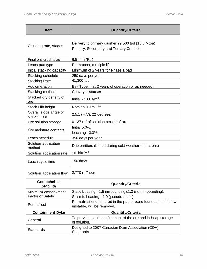
Table 4.2: Engineering Design Criteria
Item Quantity/Criteria
Mine Life 10 years Life of mine (LOM) ore quantity to be stacked on heap leach pad
92 Mt
Heap Leach Facility Feasibility Design Victoria Gold
Tetra Tech February 10, 2012 10
Item Quantity/Criteria
Crushing rate, stages Delivery to primary crusher 29,500 tpd (10.3 Mtpa) Primary, Secondary and Tertiary Crusher
Final ore crush size 6.5 mm (P80) Leach pad type Permanent, multiple lift Initial stacking capacity Minimum of 2 years for Phase 1 pad Stacking schedule 250 days per year Stacking Rate 41,300 tpd Agglomeration Belt Type, first 2 years of operation or as needed. Stacking method Conveyor-stacker Stacked dry density of ore Initial - 1.60 t/m3
Stack / lift height Nominal 10 m lifts Overall slope angle of stacked ore 2.5:1 (H:V), 22 degrees
Ore solution storage 0.137 m3 of solution per m3 of ore
Ore moisture contents Initial 5.0%, leaching 13.3%,
Leach schedule 350 days per year Solution application method Drip emitters (buried during cold weather operations)
Solution application rate 10 l/hr/m2
Leach cycle time 150 days
Solution application flow 2,770 m3/hour
Geotechnical Stability Quantity/Criteria
Minimum embankment Factor of Safety
Static Loading - 1.5 (impounding),1.3 (non-impounding), Seismic Loading - 1.0 (pseudo-static)
Permafrost Permafrost encountered in the pad or pond foundations, if thaw unstable, will be removed.
Containment Dyke Quantity/Criteria
General To provide stable confinement of the ore and in-heap storage of solution.
Standards Designed to 2007 Canadian Dam Association (CDA) Standards.
Heap Leach Facility Feasibility Design Victoria Gold
Tetra Tech February 10, 2012 11
Item Quantity/Criteria
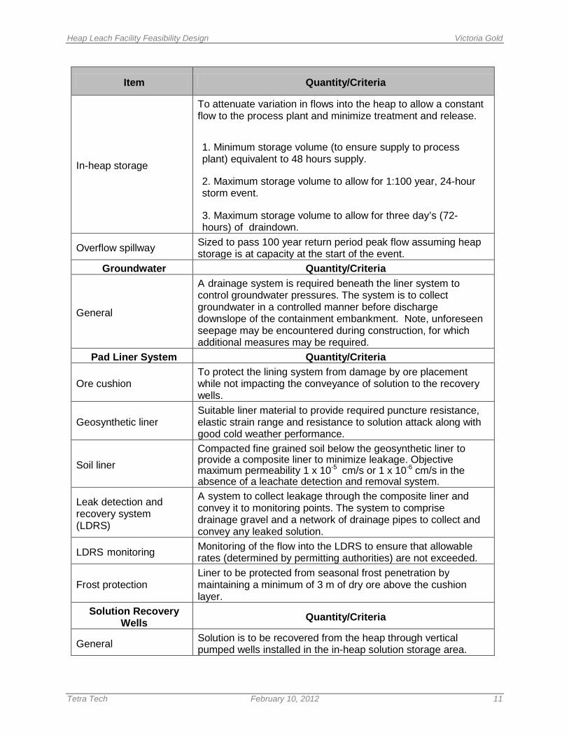
In-heap storage
To attenuate variation in flows into the heap to allow a constant flow to the process plant and minimize treatment and release. 1. Minimum storage volume (to ensure supply to process plant) equivalent to 48 hours supply. 2. Maximum storage volume to allow for 1:100 year, 24-hour storm event. 3. Maximum storage volume to allow for three day’s (72-hours) of draindown.
Overflow spillway Sized to pass 100 year return period peak flow assuming heap storage is at capacity at the start of the event.
Groundwater Quantity/Criteria
General
A drainage system is required beneath the liner system to control groundwater pressures. The system is to collect groundwater in a controlled manner before discharge downslope of the containment embankment. Note, unforeseen seepage may be encountered during construction, for which additional measures may be required.
Pad Liner System Quantity/Criteria
Ore cushion To protect the lining system from damage by ore placement while not impacting the conveyance of solution to the recovery wells.
Geosynthetic liner Suitable liner material to provide required puncture resistance, elastic strain range and resistance to solution attack along with good cold weather performance.
Soil liner Compacted fine grained soil below the geosynthetic liner to provide a composite liner to minimize leakage. Objective maximum permeability 1 x 10⁻⁵ cm/s or 1 x 10⁻⁶ cm/s in the absence of a leachate detection and removal system.
Leak detection and recovery system (LDRS)
A system to collect leakage through the composite liner and convey it to monitoring points. The system to comprise drainage gravel and a network of drainage pipes to collect and convey any leaked solution.
LDRS monitoring Monitoring of the flow into the LDRS to ensure that allowable rates (determined by permitting authorities) are not exceeded.
Frost protection Liner to be protected from seasonal frost penetration by maintaining a minimum of 3 m of dry ore above the cushion layer.
Solution Recovery Wells Quantity/Criteria
General Solution is to be recovered from the heap through vertical pumped wells installed in the in-heap solution storage area.
Heap Leach Facility Feasibility Design Victoria Gold
Tetra Tech February 10, 2012 12
Item Quantity/Criteria
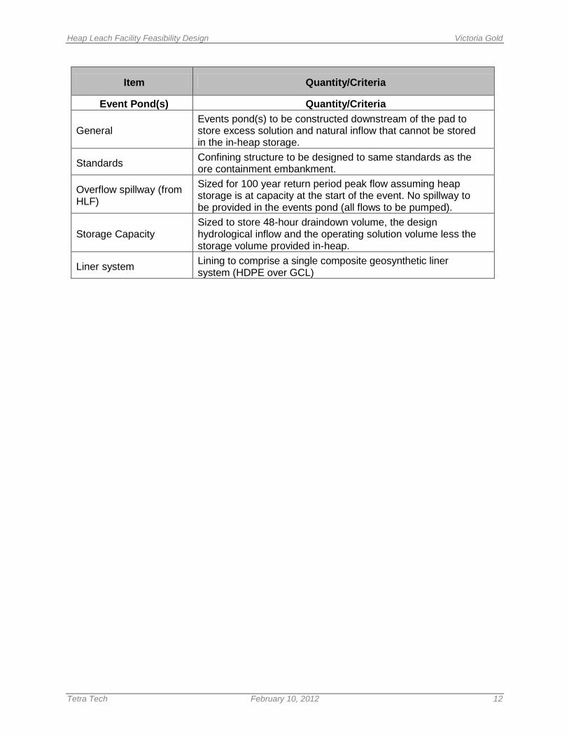
Event Pond(s) Quantity/Criteria
General Events pond(s) to be constructed downstream of the pad to store excess solution and natural inflow that cannot be stored in the in-heap storage.
Standards Confining structure to be designed to same standards as the ore containment embankment.
Overflow spillway (from HLF)
Sized for 100 year return period peak flow assuming heap storage is at capacity at the start of the event. No spillway to be provided in the events pond (all flows to be pumped).
Storage Capacity Sized to store 48-hour draindown volume, the design hydrological inflow and the operating solution volume less the storage volume provided in-heap.
Liner system Lining to comprise a single composite geosynthetic liner system (HDPE over GCL)
Heap Leach Facility Feasibility Design Victoria Gold
Tetra Tech February 10, 2012 13
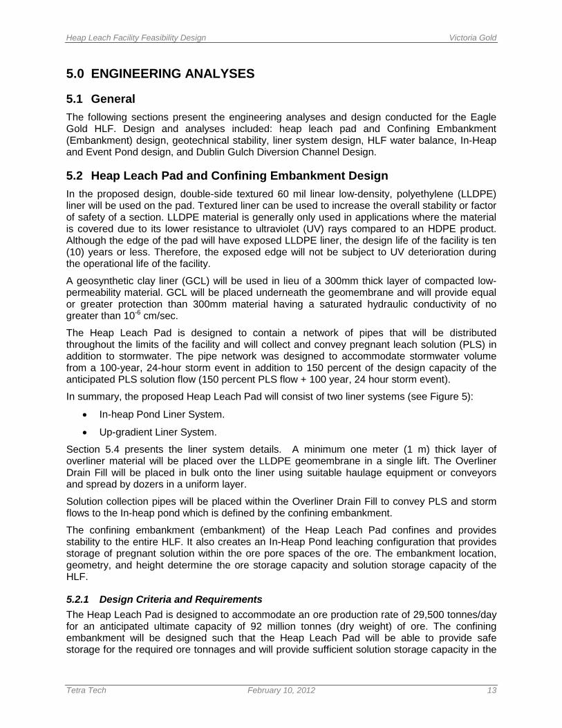
5.0 ENGINEERING ANALYSES
5.1 General The following sections present the engineering analyses and design conducted for the Eagle Gold HLF. Design and analyses included: heap leach pad and Confining Embankment (Embankment) design, geotechnical stability, liner system design, HLF water balance, In-Heap and Event Pond design, and Dublin Gulch Diversion Channel Design.
5.2 Heap Leach Pad and Confining Embankment Design In the proposed design, double-side textured 60 mil linear low-density, polyethylene (LLDPE) liner will be used on the pad. Textured liner can be used to increase the overall stability or factor of safety of a section. LLDPE material is generally only used in applications where the material is covered due to its lower resistance to ultraviolet (UV) rays compared to an HDPE product. Although the edge of the pad will have exposed LLDPE liner, the design life of the facility is ten (10) years or less. Therefore, the exposed edge will not be subject to UV deterioration during the operational life of the facility.
A geosynthetic clay liner (GCL) will be used in lieu of a 300mm thick layer of compacted low-permeability material. GCL will be placed underneath the geomembrane and will provide equal or greater protection than 300mm material having a saturated hydraulic conductivity of no greater than 10-6 cm/sec.
The Heap Leach Pad is designed to contain a network of pipes that will be distributed throughout the limits of the facility and will collect and convey pregnant leach solution (PLS) in addition to stormwater. The pipe network was designed to accommodate stormwater volume from a 100-year, 24-hour storm event in addition to 150 percent of the design capacity of the anticipated PLS solution flow (150 percent PLS flow + 100 year, 24 hour storm event).
In summary, the proposed Heap Leach Pad will consist of two liner systems (see Figure 5):
• In-heap Pond Liner System.
• Up-gradient Liner System.
Section 5.4 presents the liner system details. A minimum one meter (1 m) thick layer of overliner material will be placed over the LLDPE geomembrane in a single lift. The Overliner Drain Fill will be placed in bulk onto the liner using suitable haulage equipment or conveyors and spread by dozers in a uniform layer.
Solution collection pipes will be placed within the Overliner Drain Fill to convey PLS and storm flows to the In-heap pond which is defined by the confining embankment.
The confining embankment (embankment) of the Heap Leach Pad confines and provides stability to the entire HLF. It also creates an In-Heap Pond leaching configuration that provides storage of pregnant solution within the ore pore spaces of the ore. The embankment location, geometry, and height determine the ore storage capacity and solution storage capacity of the HLF.
5.2.1 Design Criteria and Requirements The Heap Leach Pad is designed to accommodate an ore production rate of 29,500 tonnes/day for an anticipated ultimate capacity of 92 million tonnes (dry weight) of ore. The confining embankment will be designed such that the Heap Leach Pad will be able to provide safe storage for the required ore tonnages and will provide sufficient solution storage capacity in the
Heap Leach Facility Feasibility Design Victoria Gold
Tetra Tech February 10, 2012 14
In-Heap Pond. The requirements for the In-Heap Pond and Confining Embankment are described in the following sections.
5.2.2 Confining Embankment The HLF confining embankment (Embankment) will be constructed during initial construction. It will provide heap stability and containment of process solutions in the In-Heap Pond. The embankment dam is designed as an earthfill/rockfill structure with a geomembrane lined upstream dam face and appropriate filter and transition zones to ensure containment integrity. Appendix C presents the filter design and Section 6.2 provides details of the foundation preparation; embankment fill materials and sources; and anticipated construction methods.
The Embankment height was determined in conjunction with the In-Heap Pond storage capacity. The embankment height depends on the In-Heap Pond storage capacity and vice versa. The capacity of the In-Heap Pond and embankment height are discussed further in Appendix C in the technical memorandum titled In-Heap Pond, Spillway and Event Ponds Sizing.
The Embankment section includes an 10 m crest width at Elevation 891 m for road and pipeline access and 2.5H:1V upstream and downstream slopes (see Figure 7). The fill types include compacted rockfill material taken from selective excavations for placement in the central and downstream section of the Embankment. The pre-production overburden removal excavations are estimated to include sufficient quantities of materials suitable for embankment fill and site grading fills. More competent durable rock for production of required drain rock will be quarried and crushed from required site excavations and filter materials will be produced from screening of placer fill materials in the Dublin Gulch valley bottom that require excavation.
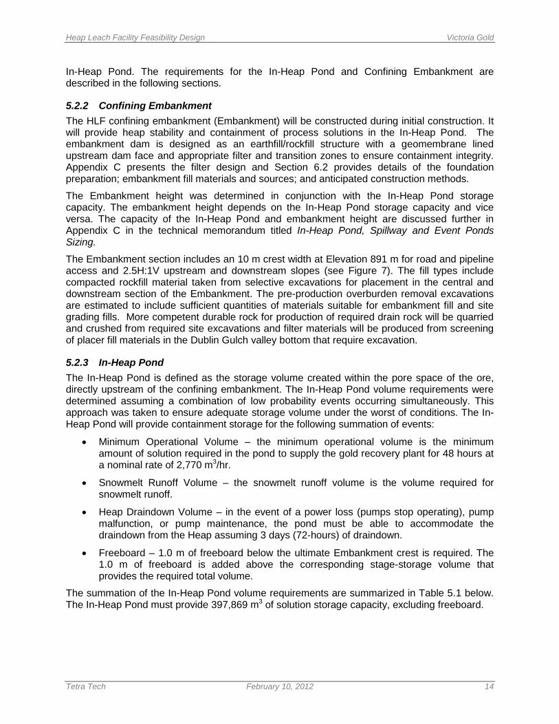
5.2.3 In-Heap Pond The In-Heap Pond is defined as the storage volume created within the pore space of the ore, directly upstream of the confining embankment. The In-Heap Pond volume requirements were determined assuming a combination of low probability events occurring simultaneously. This approach was taken to ensure adequate storage volume under the worst of conditions. The In-Heap Pond will provide containment storage for the following summation of events:
• Minimum Operational Volume – the minimum operational volume is the minimum amount of solution required in the pond to supply the gold recovery plant for 48 hours at a nominal rate of 2,770 m3/hr.
• Snowmelt Runoff Volume – the snowmelt runoff volume is the volume required for snowmelt runoff.
• Heap Draindown Volume – in the event of a power loss (pumps stop operating), pump malfunction, or pump maintenance, the pond must be able to accommodate the draindown from the Heap assuming 3 days (72-hours) of draindown.
• Freeboard – 1.0 m of freeboard below the ultimate Embankment crest is required. The 1.0 m of freeboard is added above the corresponding stage-storage volume that provides the required total volume.
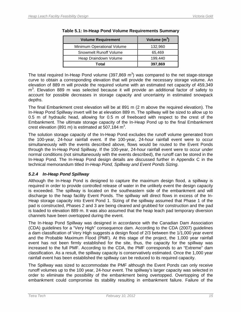
The summation of the In-Heap Pond volume requirements are summarized in Table 5.1 below. The In-Heap Pond must provide 397,869 m3 of solution storage capacity, excluding freeboard.
Heap Leach Facility Feasibility Design Victoria Gold
Tetra Tech February 10, 2012 15
Table 5.1: In-Heap Pond Volume Requirements Summary
Volume Requirement Volume (m3)
Minimum Operational Volume 132,960 Snowmelt Runoff Volume 65,469 Heap Draindown Volume 199,440
Total 397,869 The total required In-Heap Pond volume (397,869 m3) was compared to the net stage-storage curve to obtain a corresponding elevation that will provide the necessary storage volume. An elevation of 889 m will provide the required volume with an estimated net capacity of 459,349 m3. Elevation 889 m was selected because it will provide an additional factor of safety to account for possible decreases in storage capacity and uncertainty in estimated snowpack depths.
The final Embankment crest elevation will be at 891 m (2 m above the required elevation). The In-Heap Pond Spillway invert will be at elevation 889 m. The spillway will be sized to allow up to 0.5 m of hydraulic head, allowing for 0.5 m of freeboard with respect to the crest of the Embankment. The ultimate storage capacity of the In-Heap Pond up to the final Embankment crest elevation (891 m) is estimated at 507,184 m3.
The solution storage capacity of the In-Heap Pond excludes the runoff volume generated from the 100-year, 24-hour rainfall event. If the 100-year, 24-hour rainfall event were to occur simultaneously with the events described above, flows would be routed to the Event Ponds through the In-Heap Pond Spillway. If the 100-year, 24-hour rainfall event were to occur under normal conditions (not simultaneously with the events described), the runoff can be stored in the In-Heap Pond. The In-Heap Pond design details are discussed further in Appendix C in the technical memorandum titled In-Heap Pond, Spillway and Event Ponds Sizing.
5.2.4 In-Heap Pond Spillway Although the In-Heap Pond is designed to capture the maximum design flood, a spillway is required in order to provide controlled release of water in the unlikely event the design capacity is exceeded. The spillway is located on the southeastern side of the embankment and will discharge to the heap facility Event Ponds. The spillway will direct flows in excess of the In-Heap storage capacity into Event Pond 1. Sizing of the spillway assumed that Phase 1 of the pad is constructed, Phases 2 and 3 are being cleared and grubbed for construction and the pad is loaded to elevation 889 m. It was also assumed that the heap leach pad temporary diversion channels have been overtopped during the event.
The In-Heap Pond Spillway was designed in accordance with the Canadian Dam Association (CDA) guidelines for a “Very High” consequence dam. According to the CDA (2007) guidelines a dam classification of Very High suggests a design flood of 2/3 between the 1/1,000 year event and the Probable Maximum Flood (PMF). At this stage of the project, the 1,000 year rainfall event has not been firmly established for the site, thus, the capacity for the spillway was increased to the full PMF. According to the CDA, the PMF corresponds to an “Extreme” dam classification. As a result, the spillway capacity is conservatively estimated. Once the 1,000 year rainfall event has been established the spillway can be reduced to its required capacity.
The Spillway was sized to accommodate the PMF although the Event Ponds can only receive runoff volumes up to the 100 year, 24-hour event. The spillway’s larger capacity was selected in order to eliminate the possibility of the embankment being overtopped. Overtopping of the embankment could compromise its stability resulting in embankment failure. Failure of the
Heap Leach Facility Feasibility Design Victoria Gold
Tetra Tech February 10, 2012 16
embankment would be an even more catastrophic event as it would result in a much larger volume of solution to be released. A higher capacity spillway will ensure that any flows in excess of the In-Heap Pond capacity can be routed downstream.
The In-Heap Pond Spillway will be rectangular in shape and constructed of concrete. The spillway will have a bottom width of 5 m and a depth of 2 m. Should the PMF occur, the spillway will have 0.5 m of freeboard. The In-Heap Pond Spillway design details are discussed further in Appendix C in the technical memorandum titled In-Heap Pond, Spillway and Event Ponds Sizing. See Figures 13-14 for the spillway design.
5.3 Event Ponds The capacity of the Event Ponds are dependent on the events retained in the In-Heap Pond as described in section 5.0. The Event Ponds serve as an overflow containment area that provides additional storage in case the In-Heap Pond capacity is exceeded. The Event Ponds are sized to provide containment storage for the 100-year, 24-hour event assuming the In-Heap Pond is at maximum capacity. Assuming fully saturated conditions (no rainfall losses) upstream of the Embankment the estimated rainfall volume reporting to the Event Ponds is 132,200 m3. The Event Ponds layout can be seen in Figures 15-16.
The configuration of the Event Ponds have a combined operational storage capacity of approximately 182,846 m3 with 1 m of freeboard. Event Pond 1 (closest to the Embankment) has a storage capacity of 92,153 m3 and Event Pond 2 (farthest from the Embankment) has a storage capacity of 90,693 m3. The combined ultimate storage capacity of the Event Ponds without freeboard is 216,713 m3.
5.4 Liner System Design
5.4.1 General The liner for the leach pad and event ponds will consist of a composite geomembrane and underlying low-permeability bedding material, which is the state-of-practice liner system for heap leach facilities. The primary purpose of the composite liner system is to prevent the loss of HLF process solutions for both environmental and economic reasons. In addition to playing a role in preventing leakage, the underliner beneath the geomembrane is necessary as a transition layer between the geomembrane and the prepared foundation.
A geosynthetic clay liner (GCL) will be used in lieu of a 300mm thick layer of compacted low-permeability material due to the lack of suitable onsite soils in sufficient quantities. The GCL soil liner provides an equivalent 300 mm minimum thickness of 1x10⁻⁶ cm/sec or lower permeability soil layer.
Differential settlement on the liner system due to variable loading conditions was considered in the liner design. LaGatta et al. (1997) performed tests to measure the hydraulic conductivity (k) of GCLs exposed to differential settlement. They found that in most cases, needle-punched GCLs maintained a k ≤ 1x10⁻⁷ cm/sec even when exposed to tensile strains of up to 10 percent or more, depending on test conditions. Overlapped seams maintained the low k value even when slippage occurred along the overlap. Their literature review indicated that compacted clay subliner can experience failure at tensile strains as little as 0.1 to 4 percent. Thus GCLs may be more resistant to damage from differential settlement than compacted clay liners.
The higher cost for GCL can be offset by cost savings in construction time due to the relatively rapid deployment of the GCL rolls during geomembrane liner installation, where no moisture conditioning or compaction is required. The GCL surface provides rock puncture protection to
Heap Leach Facility Feasibility Design Victoria Gold
Tetra Tech February 10, 2012 17
the overlying geomembrane liner, and only requires a smoothed and compacted subgrade surface graded to drain and support the composite pad liner system.
Free-draining granular material will be placed on top of the pad liner together with a network of collection pipes to collect and drain process solutions and storm infiltration, and to minimize hydraulic heads on the liner, thereby reducing the risk of leakage. Piezometers will be installed within the liner cover fill at the strategic locations to monitor the hydraulic head on the liner system during pad operation.
The in-heap pond will have a double-geomembrane liner together with a leak detection system. The leak detection system will be installed between the two geomembranes to monitor and contain any leaks through the top geomembrane.
The event ponds will be lined with a single-geomembrane liner since it will be empty during normal HLPF operations except during short duration excess water balance conditions from storm events or upset operational flows. The design assumes that any solution in the storm pond will be pumped out and returned to the process circuit within 72 hours. Details of the pad and pond liner systems are shown on Figures 3 through 6.
5.4.2 Liner Subgrade
Subgrade preparation for the GCL placement will involve subgrade compaction to 95 percent of the maximum dry density based on ASTM D 698. Rocks larger than 38 mm in diameter will first be removed from the upper 150 mm of the subgrade prior to compaction. Areas to receive liner that consisted of weathered rock or site grading fill will require import of fine-grained material to cover the surface and form a suitable subgrade.
5.4.3 Geomembrane Selection
The critical aspects of geomembrane selection for this project include puncture resistance, elongation capacity (elasticity) to withstand the anticipated foundation settlement under the ore heap, adequate interface shear strength between the pad geomembrane and the underlying soil liner or GCL and overlying cover fill for heap stability, and satisfactory performance under exposure to climatic conditions (temperature expansion and contraction, wind forces, and sunlight ultraviolet (UV) effects).
The geomembrane types typically used for heap leach facilities are LLDPE, HDPE, and polyvinyl chloride (PVC). The more flexible LLDPE and PVC geomembranes are best for buried applications subjected to high loads such as the leach pad. HDPE geomembrane is best for exposed applications such as the ponds and ditches. LLDPE geomembranes were selected for the leach pad including the in-heap pond geomembrane, and HDPE geomembranes were selected for the event ponds for the following reasons:
• LLDPE geomembrane has significantly better elongation performance, puncture resistance, interface friction strength, and stress cracking resistance compared to HDPE geomembrane;
• LLDPE geomembrane remains flexible at temperatures well below freezing to about -25°C with a low temperature brittleness of -70°C according to ASTM D-746;
• HDPE geomembrane has better chemical and UV resistance; and
• LLDPE geomembrane can be readily seamed to HDPE geomembrane.
A 1.5-mm (60-mil) LLDPE geomembrane was selected for the leach pad, based on performance requirements and past design and construction experience. The geomembrane will be double-
Heap Leach Facility Feasibility Design Victoria Gold
Tetra Tech February 10, 2012 18
side textured above the GCL to enhance heap stability and construction safety. The event pond geomembrane will be 2.0-mm (80-mil) single-side textured HDPE with the textured side up for traction.
A geocomposite (drainage net) will be installed between the in-heap pond geomembranes and will tie to a corner leak detection sump and pipe system for collecting and removing any leaks through the top geomembrane. The geocomposite will consist of a 5-mm (200-mil) geonet heat-laminated on both sides with 270 gr/sq m (8 oz/sq yd) nonwoven geotextile. The geonet is a netlike polymeric material formed from intersecting ribs integrally joined at the junctions and is used to facilitate drainage between the gemembranes.
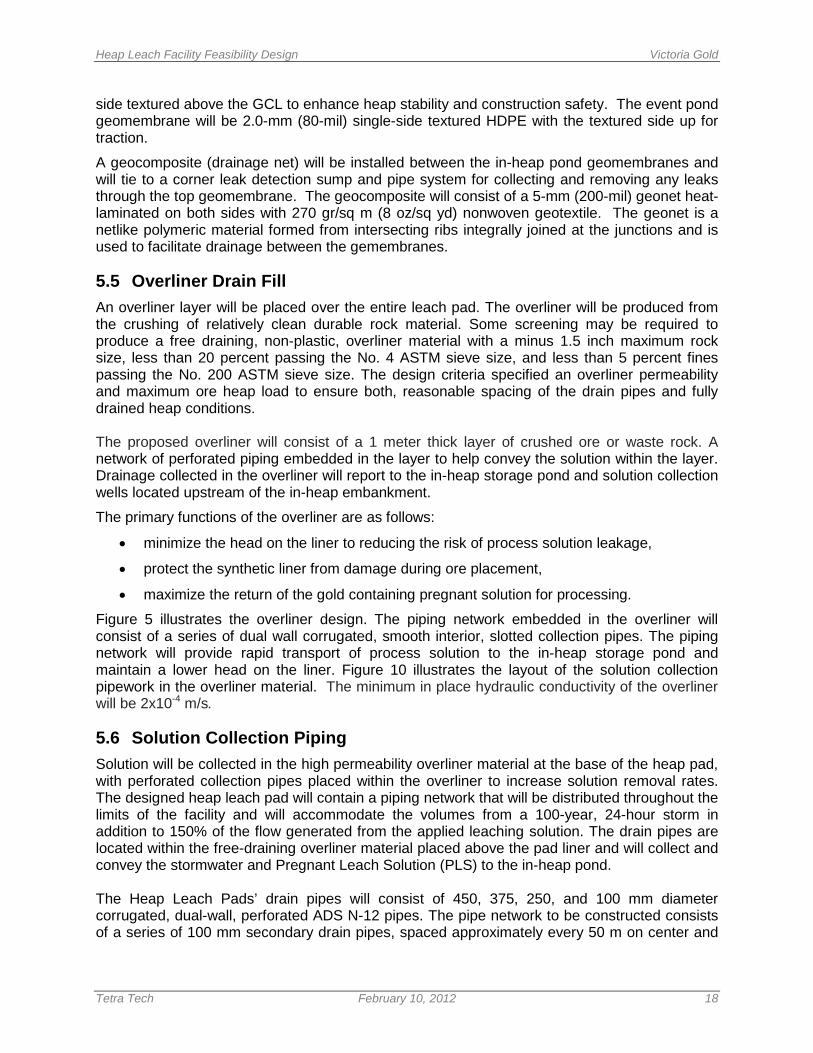
5.5 Overliner Drain Fill An overliner layer will be placed over the entire leach pad. The overliner will be produced from the crushing of relatively clean durable rock material. Some screening may be required to produce a free draining, non-plastic, overliner material with a minus 1.5 inch maximum rock size, less than 20 percent passing the No. 4 ASTM sieve size, and less than 5 percent fines passing the No. 200 ASTM sieve size. The design criteria specified an overliner permeability and maximum ore heap load to ensure both, reasonable spacing of the drain pipes and fully drained heap conditions. The proposed overliner will consist of a 1 meter thick layer of crushed ore or waste rock. A network of perforated piping embedded in the layer to help convey the solution within the layer. Drainage collected in the overliner will report to the in-heap storage pond and solution collection wells located upstream of the in-heap embankment.
The primary functions of the overliner are as follows:
• minimize the head on the liner to reducing the risk of process solution leakage,
• protect the synthetic liner from damage during ore placement,
• maximize the return of the gold containing pregnant solution for processing.
Figure 5 illustrates the overliner design. The piping network embedded in the overliner will consist of a series of dual wall corrugated, smooth interior, slotted collection pipes. The piping network will provide rapid transport of process solution to the in-heap storage pond and maintain a lower head on the liner. Figure 10 illustrates the layout of the solution collection pipework in the overliner material. The minimum in place hydraulic conductivity of the overliner will be 2x10⁻⁴ m/s.
5.6 Solution Collection Piping Solution will be collected in the high permeability overliner material at the base of the heap pad, with perforated collection pipes placed within the overliner to increase solution removal rates. The designed heap leach pad will contain a piping network that will be distributed throughout the limits of the facility and will accommodate the volumes from a 100-year, 24-hour storm in addition to 150% of the flow generated from the applied leaching solution. The drain pipes are located within the free-draining overliner material placed above the pad liner and will collect and convey the stormwater and Pregnant Leach Solution (PLS) to the in-heap pond. The Heap Leach Pads’ drain pipes will consist of 450, 375, 250, and 100 mm diameter corrugated, dual-wall, perforated ADS N-12 pipes. The pipe network to be constructed consists of a series of 100 mm secondary drain pipes, spaced approximately every 50 m on center and
Heap Leach Facility Feasibility Design Victoria Gold
Tetra Tech February 10, 2012 19
arranged in a “herringbone” pattern around the larger pipes that will convey the collected fluid, i.e., PLS and stormwater flows. The larger pipes mentioned consist of 250 mm collector pipes transmitting their flows to the 375 mm primary pipes which ultimately drain their collected and transmitting fluid to the 450 mm header pipes. In order to maximize the efficiency of the ore’s drainage and to minimize the potential for leakage through the pads’ liner system, the hydraulic head above the liner was designed to be less than a maximum height of 2.0 m. Calculating the hydraulic head the minimum secondary pipe spacing of 50 m on center will allow for efficient drainage and also represents a spacing that considers ease of placement during construction. The spacing of the space can vary depending on the slope of the contributing area.
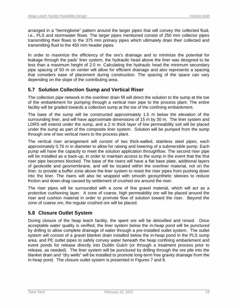
5.7 Solution Collection Sump and Vertical Riser The collection pipe network in the overliner drain fill will direct the solution to the sump at the toe of the embankment for pumping through a vertical riser pipe to the process plant. The entire facility will be graded towards a collection sump at the toe of the confining embankment.
The base of the sump will be constructed approximately 1.5 m below the elevation of the surrounding liner, and will have approximate dimensions of 15 m by 30 m. The liner system and LDRS will extend under the sump, and a 2 m thick layer of low permeability soil will be placed under the sump as part of the composite liner system. Solution will be pumped from the sump through one of two vertical risers to the process plant.
The vertical riser arrangement will consist of two thick-walled, stainless steel pipes, each approximately 0.76 m in diameter to allow for raising and lowering of a submersible pump. Each pump will have the capacity to meet the solution application throughflow. The second riser pipe will be installed as a back-up, in order to maintain access to the sump in the event that the first riser pipe becomes blocked. The base of the risers will have a flat base plate, additional layers of geotextile and geomembrane, and will be located within the overliner material, not on the liner, to provide a buffer zone above the liner system to resist the riser pipes from pushing down into the liner. The risers will also be wrapped with smooth geosynthetic sleeves to reduce friction and down-drag caused by settlement of crushed ore around the riser.
The riser pipes will be surrounded with a zone of fine gravel material, which will act as a protective cushioning layer. A zone of coarse, high permeability ore will be placed around the riser and cushion material in order to promote flow of solution toward the riser. Beyond the zone of coarse ore, the regular crushed ore will be placed.
5.8 Closure Outlet System During closure of the heap leach facility, the spent ore will be detoxified and rinsed. Once acceptable water quality is verified, the liner system below the in-heap pond will be punctured by drilling to allow complete drainage of water through a pre-installed outlet system. The outlet system will consist of a gravel blanket drain installed below the in-heap pond in the PLS sump area, and PE outlet pipes to safely convey water beneath the heap confining embankment and event ponds for release directly into Dublin Gulch (or through a treatment process prior to release, as needed). The liner system will be punctured by drilling through the ore pile into the blanket drain and “dry wells” will be installed to promote long-term free gravity drainage from the in-heap pond. The closure outlet system is presented in Figures 7 and 8.
Heap Leach Facility Feasibility Design Victoria Gold
Tetra Tech February 10, 2012 20
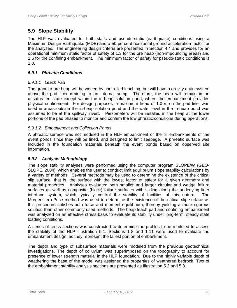
5.9 Slope Stability The HLF was evaluated for both static and pseudo-static (earthquake) conditions using a Maximum Design Earthquake (MDE) and a 50 percent horizontal ground acceleration factor for the analyses. The engineering design criteria are presented in Section 4.4 and provides for an operational minimum static factor of safety of 1.3 for the ore heap (non-impounding areas) and 1.5 for the confining embankment. The minimum factor of safety for pseudo-static conditions is 1.0.
5.9.1 Phreatic Conditions
5.9.1.1 Leach Pad The granular ore heap will be wetted by controlled leaching, but will have a gravity drain system above the pad liner draining to an internal sump. Therefore, the heap will remain in an unsaturated state except within the in-heap solution pond, where the embankment provides physical confinement. For design purposes, a maximum head of 1.0 m on the pad liner was used in areas outside the in-heap solution pond and the water level in the in-heap pond was assumed to be at the spillway invert. Piezometers will be installed in the heap at the lower portions of the pad phases to monitor and confirm the low phreatic conditions during operations.
5.9.1.2 Embankment and Collection Ponds A phreatic surface was not modeled in the HLF embankment or the fill embankments of the event ponds since they will be lined, and designed to limit seepage. A phreatic surface was included in the foundation materials beneath the event ponds based on observed site information.
5.9.2 Analysis Methodology The slope stability analyses were performed using the computer program SLOPE/W (GEO-SLOPE, 2004), which enables the user to conduct limit equilibrium slope stability calculations by a variety of methods. Several methods may be used to determine the existence of the critical slip surface, that is, the surface with the lowest factor of safety for a given geometry and material properties. Analyses evaluated both smaller and larger circular and wedge failure surfaces as well as composite (block) failure surfaces with sliding along the underlying liner interface system, which typically control the stability of facilities of this nature. The Morgenstern-Price method was used to determine the existence of the critical slip surface as this procedure satisfies both force and moment equilibrium, thereby yielding a more rigorous solution than other commonly used methods. The heap leach pad and confining embankment was analyzed on an effective stress basis to evaluate its stability under long-term, steady state loading conditions.
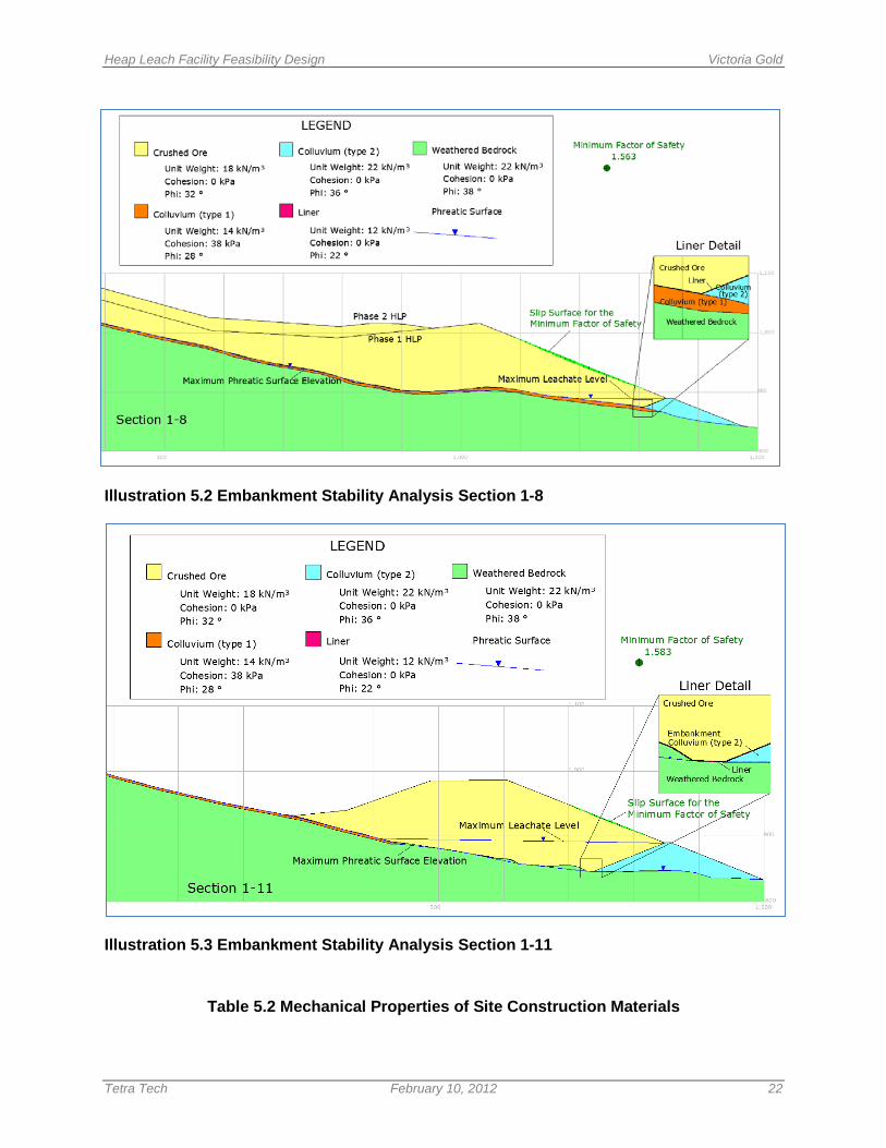
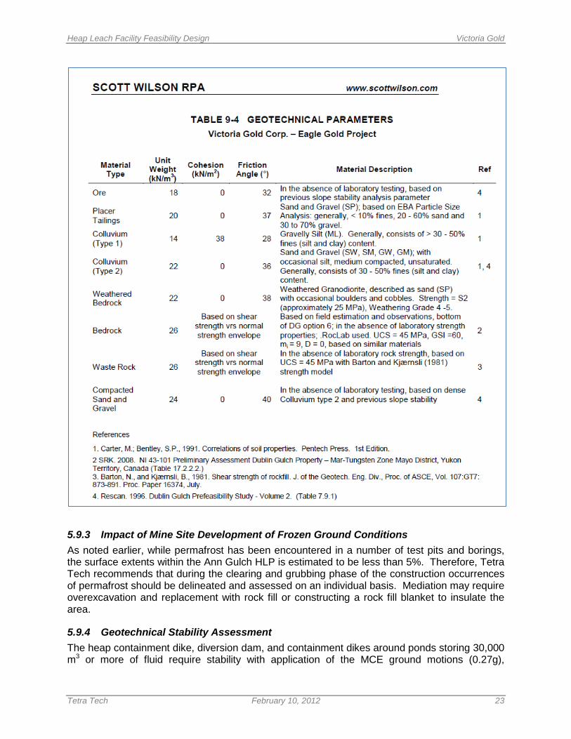
A series of cross sections was constructed to determine the profiles to be modeled to assess the stability of the HLP Illustration 5.1. Sections 1-8 and 1-11 were used to evaluate the embankment design, as they represent the tallest portion of embankment. The depth and type of subsurface materials were modeled from the previous geotechnical investigations. The depth of colluvium was superimposed on the topography to account for presence of lower strength material in the HLP foundation. Due to the highly variable depth of weathering the base of the model was assigned the properties of weathered bedrock. Two of the embankment stability analysis sections are presented as Illustration 5.2 and 5.3.
Heap Leach Facility Feasibility Design Victoria Gold
Tetra Tech February 10, 2012 21
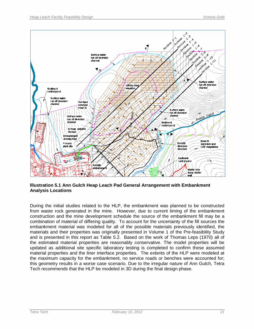
Illustration 5.1 Ann Gulch Heap Leach Pad General Arrangement with Embankment Analysis Locations
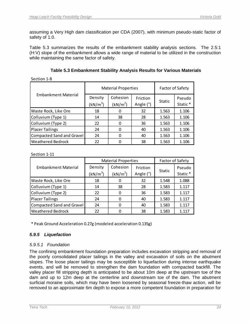
During the initial studies related to the HLP, the embankment was planned to be constructed from waste rock generated in the mine. However, due to current timing of the embankment construction and the mine development schedule the source of the embankment fill may be a combination of material of differing quality. To account for the uncertainty of the fill sources the embankment material was modeled for all of the possible materials previously identified, the materials and their properties was originally presented in Volume 1 of the Pre-feasibility Study and is presented in this report as Table 5.2. Based on the work of Thomas Leps (1970) all of the estimated material properties are reasonably conservative. The model properties will be updated as additional site specific laboratory testing is completed to confirm these assumed material properties and the liner interface properties. The extents of the HLP were modeled at the maximum capacity for the embankment, no service roads or benches were accounted for; this geometry results in a worse case scenario. Due to the irregular nature of Ann Gulch, Tetra Tech recommends that the HLP be modeled in 3D during the final design phase.
Heap Leach Facility Feasibility Design Victoria Gold
Tetra Tech February 10, 2012 22
Illustration 5.2 Embankment Stability Analysis Section 1-8
Illustration 5.3 Embankment Stability Analysis Section 1-11
Table 5.2 Mechanical Properties of Site Construction Materials
Heap Leach Facility Feasibility Design Victoria Gold
Tetra Tech February 10, 2012 23
5.9.3 Impact of Mine Site Development of Frozen Ground Conditions As noted earlier, while permafrost has been encountered in a number of test pits and borings, the surface extents within the Ann Gulch HLP is estimated to be less than 5%. Therefore, Tetra Tech recommends that during the clearing and grubbing phase of the construction occurrences of permafrost should be delineated and assessed on an individual basis. Mediation may require overexcavation and replacement with rock fill or constructing a rock fill blanket to insulate the area.
5.9.4 Geotechnical Stability Assessment The heap containment dike, diversion dam, and containment dikes around ponds storing 30,000 m3 or more of fluid require stability with application of the MCE ground motions (0.27g),
Heap Leach Facility Feasibility Design Victoria Gold
Tetra Tech February 10, 2012 24
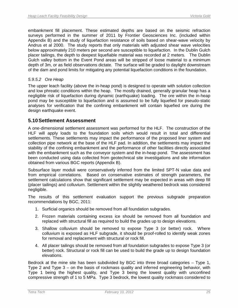
assuming a Very High dam classification per CDA (2007), with minimum pseudo-static factor of safety of 1.0. Table 5.3 summarizes the results of the embankment stability analysis sections. The 2.5:1 (H:V) slope of the embankment allows a wide range of material to be utilized in the construction while maintaining the same factor of safety.
Table 5.3 Embankment Stability Analysis Results for Various Materials
5.9.5 Liquefaction
5.9.5.1 Foundation The confining embankment foundation preparation includes excavation stripping and removal of the poorly consolidated placer tailings in the valley and excavation of soils on the abutment slopes. The loose placer tailings may be susceptible to liquefaction during intense earthquake events, and will be removed to strengthen the dam foundation with compacted backfill. The valley placer fill stripping depth is anticipated to be about 10m deep at the upstream toe of the dam and up to 12m deep at the centerline and downstream toe of the dam. The abutment surficial moraine soils, which may have been loosened by seasonal freeze-thaw action, will be removed to an approximate 6m depth to expose a more competent foundation in preparation for
Section 1-8
Density (kN/m3)
Cohesion (kN/m2)
Friction Angle (°)
StaticPseudo Static *
Waste Rock, Like Ore 18 0 32 1.563 1.106Colluvium (Type 1) 14 38 28 1.563 1.106Colluvium (Type 2) 22 0 36 1.563 1.106Placer Tailings 24 0 40 1.563 1.106Compacted Sand and Gravel 24 0 40 1.563 1.106Weathered Bedrock 22 0 38 1.563 1.106
Section 1-11
Density (kN/m3)
Cohesion (kN/m2)
Friction Angle (°)
StaticPseudo Static *
Waste Rock, Like Ore 18 0 32 1.548 1.088Colluvium (Type 1) 14 38 28 1.583 1.117Colluvium (Type 2) 22 0 36 1.583 1.117Placer Tailings 24 0 40 1.583 1.117Compacted Sand and Gravel 24 0 40 1.583 1.117Weathered Bedrock 22 0 38 1.583 1.117
* Peak Ground Acceleration 0.27g (modeled acceleration 0.135g)
Embankment MaterialMaterial Properties Factor of Safety
Factor of SafetyEmbankment Material
Material Properties
Heap Leach Facility Feasibility Design Victoria Gold
Tetra Tech February 10, 2012 25
embankment fill placement. These estimated depths are based on the seismic refraction surveys performed in the summer of 2011 by Frontier Geosciences Inc. (included within Appendix B) and the study of liquefaction resistance of soils based on shear-wave velocity by Andrus et al 2000. The study reports that only materials with adjusted shear wave velocities below approximately 210 meters per second are susceptible to liquefaction. In the Dublin Gulch placer tailings, the depth to deepest liquefiable material was recorded at 2 meters. The Dublin Gulch valley bottom in the Event Pond areas will be stripped of loose material to a minimum depth of 3m, or as field observations dictate. The surface will be graded to daylight downstream of the dam and pond limits for mitigating any potential liquefaction conditions in the foundation.
5.9.5.2 Ore Heap The upper leach facility (above the in-heap pond) is designed to operate with solution collection and low phreatic conditions within the heap. The mostly drained, generally granular heap has a negligible risk of liquefaction during dynamic (earthquake) loading. The ore within the in-heap pond may be susceptible to liquefaction and is assumed to be fully liquefied for pseudo-static analyses for verification that the confining embankment will contain liquefied ore during the design earthquake event.
5.10 Settlement Assessment A one-dimensional settlement assessment was performed for the HLF. The construction of the HLF will apply loads to the foundation soils which would result in total and differential settlements. These settlements may impact the performance of the proposed liner system and collection pipe network at the base of the HLF pad. In addition, the settlements may impact the stability of the confining embankment and the performance of other facilities directly associated with the embankment such as the conveyor system and the in-heap pond. The assessment has been conducted using data collected from geotechnical site investigations and site information obtained from various BGC reports (Appendix B).
Subsurface layer moduli were conservatively inferred from the limited SPT-N value data and from empirical correlations. Based on conservative estimates of strength parameters, the settlement calculations show that significant settlement may be expected in areas with deep fill (placer tailings) and colluvium. Settlement within the slightly weathered bedrock was considered negligible.
The results of this settlement evaluation support the previous subgrade preparation recommendations by BGC, 2011:
1. Surficial organics should be removed from all foundation subgrades.
2. Frozen materials containing excess ice should be removed from all foundation and replaced with structural fill as required to build the grades up to design elevations.
3. Shallow colluvium should be removed to expose Type 3 (or better) rock. Where colluvium is exposed as HLF subgrade, it should be proof-rolled to identify weak zones for removal and replacement with structural or rock fill.
4. All placer tailings should be removed from all foundation subgrades to expose Type 3 (or better) rock. Structural or rock fill can be used to build the grade up to design foundation elevations.
Bedrock at the mine site has been subdivided by BGC into three broad categories – Type 1, Type 2 and Type 3 – on the basis of rockmass quality and inferred engineering behavior, with Type 1 being the highest quality, and Type 3 being the lowest quality with unconfined compressive strength of 1 to 5 MPa. Type 3 bedrock, the lowest quality rockmass considered to
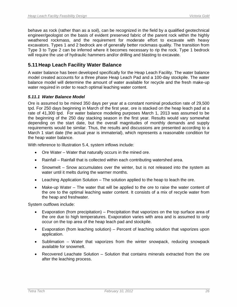
Heap Leach Facility Feasibility Design Victoria Gold
Tetra Tech February 10, 2012 26
behave as rock (rather than as a soil), can be recognized in the field by a qualified geotechnical engineer/geologist on the basis of evident preserved fabric of the parent rock within the highly weathered rockmass, and the requirement for moderate effort to excavate with heavy excavators. Types 1 and 2 bedrock are of generally better rockmass quality. The transition from Type 3 to Type 2 can be inferred where it becomes necessary to rip the rock. Type 1 bedrock will require the use of hydraulic hammers and/or drilling and blasting to excavate.
5.11 Heap Leach Facility Water Balance A water balance has been developed specifically for the Heap Leach Facility. The water balance model created accounts for a three phase Heap Leach Pad and a 100-day stockpile. The water balance model will determine the amount of water available for recycle and the fresh make-up water required in order to reach optimal leaching water content.
5.11.1 Water Balance Model Ore is assumed to be mined 350 days per year at a constant nominal production rate of 29,500 tpd. For 250 days beginning in March of the first year, ore is stacked on the heap leach pad at a rate of 41,300 tpd. For water balance modeling purposes March 1, 2013 was assumed to be the beginning of the 250 day stacking season in the first year. Results would vary somewhat depending on the start date, but the overall magnitudes of monthly demands and supply requirements would be similar. Thus, the results and discussions are presented according to a March 1 start date (the actual year is immaterial), which represents a reasonable condition for the heap water balance.
With reference to Illustration 5.4, system inflows include:
• Ore Water – Water that naturally occurs in the mined ore.
• Rainfall – Rainfall that is collected within each contributing watershed area.
• Snowmelt – Snow accumulates over the winter, but is not released into the system as water until it melts during the warmer months.
• Leaching Application Solution – The solution applied to the heap to leach the ore.
• Make-up Water – The water that will be applied to the ore to raise the water content of the ore to the optimal leaching water content. It consists of a mix of recycle water from the heap and freshwater.
System outflows include:
• Evaporation (from precipitation) – Precipitation that vaporizes on the top surface area of the ore due to high temperatures. Evaporation varies with area and is assumed to only occur on the top area of the heap leach pad and stockpile.
• Evaporation (from leaching solution) – Percent of leaching solution that vaporizes upon application.
• Sublimation – Water that vaporizes from the winter snowpack, reducing snowpack available for snowmelt.
• Recovered Leachate Solution – Solution that contains minerals extracted from the ore after the leaching process.
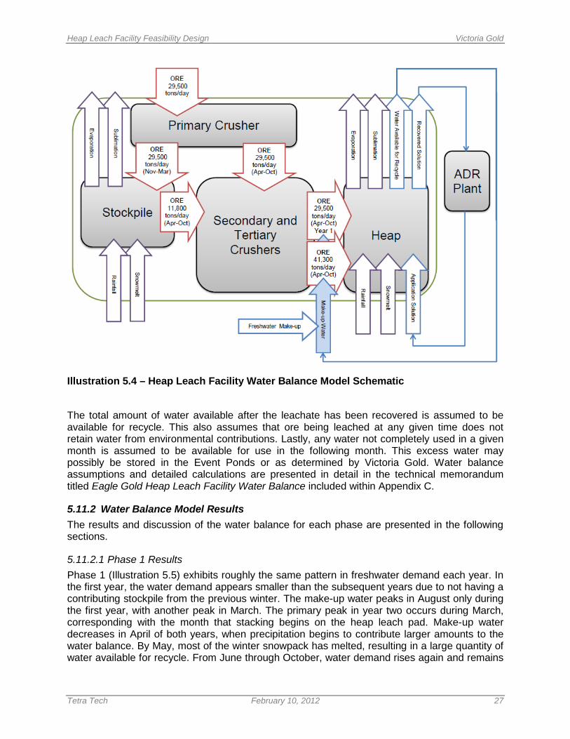
Heap Leach Facility Feasibility Design Victoria Gold
Tetra Tech February 10, 2012 27
Illustration 5.4 – Heap Leach Facility Water Balance Model Schematic
The total amount of water available after the leachate has been recovered is assumed to be available for recycle. This also assumes that ore being leached at any given time does not retain water from environmental contributions. Lastly, any water not completely used in a given month is assumed to be available for use in the following month. This excess water may possibly be stored in the Event Ponds or as determined by Victoria Gold. Water balance assumptions and detailed calculations are presented in detail in the technical memorandum titled Eagle Gold Heap Leach Facility Water Balance included within Appendix C.
5.11.2 Water Balance Model Results The results and discussion of the water balance for each phase are presented in the following sections.
5.11.2.1 Phase 1 Results Phase 1 (Illustration 5.5) exhibits roughly the same pattern in freshwater demand each year. In the first year, the water demand appears smaller than the subsequent years due to not having a contributing stockpile from the previous winter. The make-up water peaks in August only during the first year, with another peak in March. The primary peak in year two occurs during March, corresponding with the month that stacking begins on the heap leach pad. Make-up water decreases in April of both years, when precipitation begins to contribute larger amounts to the water balance. By May, most of the winter snowpack has melted, resulting in a large quantity of water available for recycle. From June through October, water demand rises again and remains
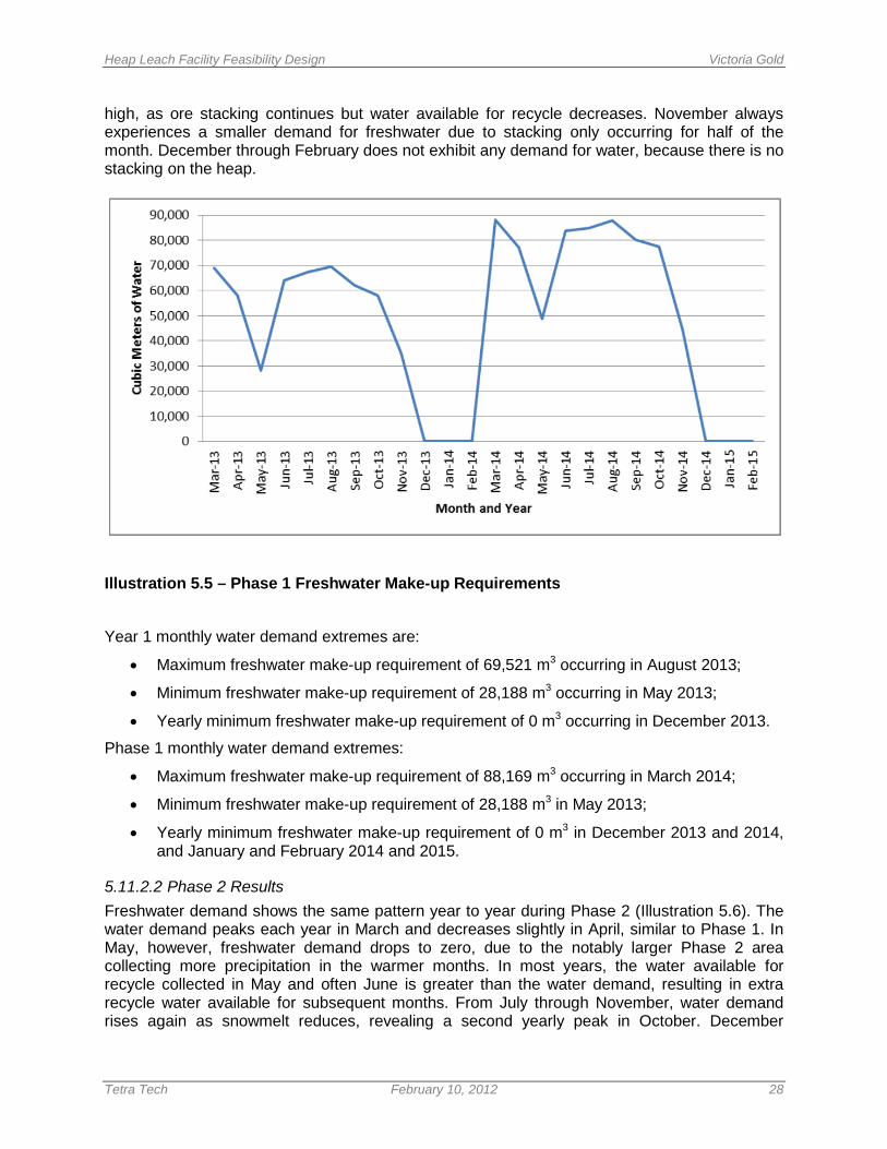
Heap Leach Facility Feasibility Design Victoria Gold
Tetra Tech February 10, 2012 28
high, as ore stacking continues but water available for recycle decreases. November always experiences a smaller demand for freshwater due to stacking only occurring for half of the month. December through February does not exhibit any demand for water, because there is no stacking on the heap.
Illustration 5.5 – Phase 1 Freshwater Make-up Requirements
Year 1 monthly water demand extremes are:
• Maximum freshwater make-up requirement of 69,521 m3 occurring in August 2013;
• Minimum freshwater make-up requirement of 28,188 m3 occurring in May 2013;
• Yearly minimum freshwater make-up requirement of 0 m3 occurring in December 2013.
Phase 1 monthly water demand extremes:
• Maximum freshwater make-up requirement of 88,169 m3 occurring in March 2014;
• Minimum freshwater make-up requirement of 28,188 m3 in May 2013;
• Yearly minimum freshwater make-up requirement of 0 m3 in December 2013 and 2014, and January and February 2014 and 2015.
5.11.2.2 Phase 2 Results Freshwater demand shows the same pattern year to year during Phase 2 (Illustration 5.6). The water demand peaks each year in March and decreases slightly in April, similar to Phase 1. In May, however, freshwater demand drops to zero, due to the notably larger Phase 2 area collecting more precipitation in the warmer months. In most years, the water available for recycle collected in May and often June is greater than the water demand, resulting in extra recycle water available for subsequent months. From July through November, water demand rises again as snowmelt reduces, revealing a second yearly peak in October. December
Heap Leach Facility Feasibility Design Victoria Gold
Tetra Tech February 10, 2012 29
through February again do not exhibit any demand for water, because there is no stacking on the heap.
Illustration 5.6 – Phase 2 Freshwater Make-up Requirements
Phase 2 monthly water demand extremes:
• Maximum freshwater make-up requirement of 87,585 m3 occurring in March 2015 through 2019;
• Secondary peak maximum freshwater make-up requirement of 62,708 m3 occurring in October 2018;
• Minimum freshwater make-up requirement of 0 m3 occurring in May 2015 through 2018, and June 2015;
• Yearly minimum freshwater make-up requirement of 0 m3 occurring in December 2015 through 2018, and January and February 2016 through 2019.
5.11.2.3 Phase 3 Results Freshwater demand exhibits the same pattern again year to year during Phase 3 (Illustration 5.7), with water demand peaks each year in March, followed by decreases in April. In May, freshwater demand drops to zero similar to Phase 2, but remains at zero through July or August. This is due to the increase of the Phase 3 area, which in turn increases precipitation and recycle water available. The second yearly peak occurs in October of each year, as it did during Phase 2. December through February again do not exhibit any demand for water, because there is no stacking taking place.
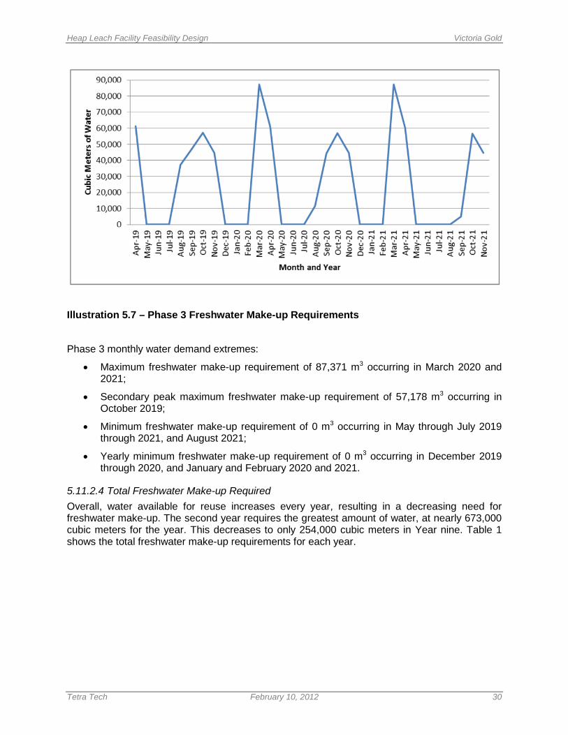
Heap Leach Facility Feasibility Design Victoria Gold
Tetra Tech February 10, 2012 30
Illustration 5.7 – Phase 3 Freshwater Make-up Requirements
Phase 3 monthly water demand extremes:
• Maximum freshwater make-up requirement of 87,371 m3 occurring in March 2020 and 2021;
• Secondary peak maximum freshwater make-up requirement of 57,178 m3 occurring in October 2019;
• Minimum freshwater make-up requirement of 0 m3 occurring in May through July 2019 through 2021, and August 2021;
• Yearly minimum freshwater make-up requirement of 0 m3 occurring in December 2019 through 2020, and January and February 2020 and 2021.
5.11.2.4 Total Freshwater Make-up Required Overall, water available for reuse increases every year, resulting in a decreasing need for freshwater make-up. The second year requires the greatest amount of water, at nearly 673,000 cubic meters for the year. This decreases to only 254,000 cubic meters in Year nine. Table 1 shows the total freshwater make-up requirements for each year.
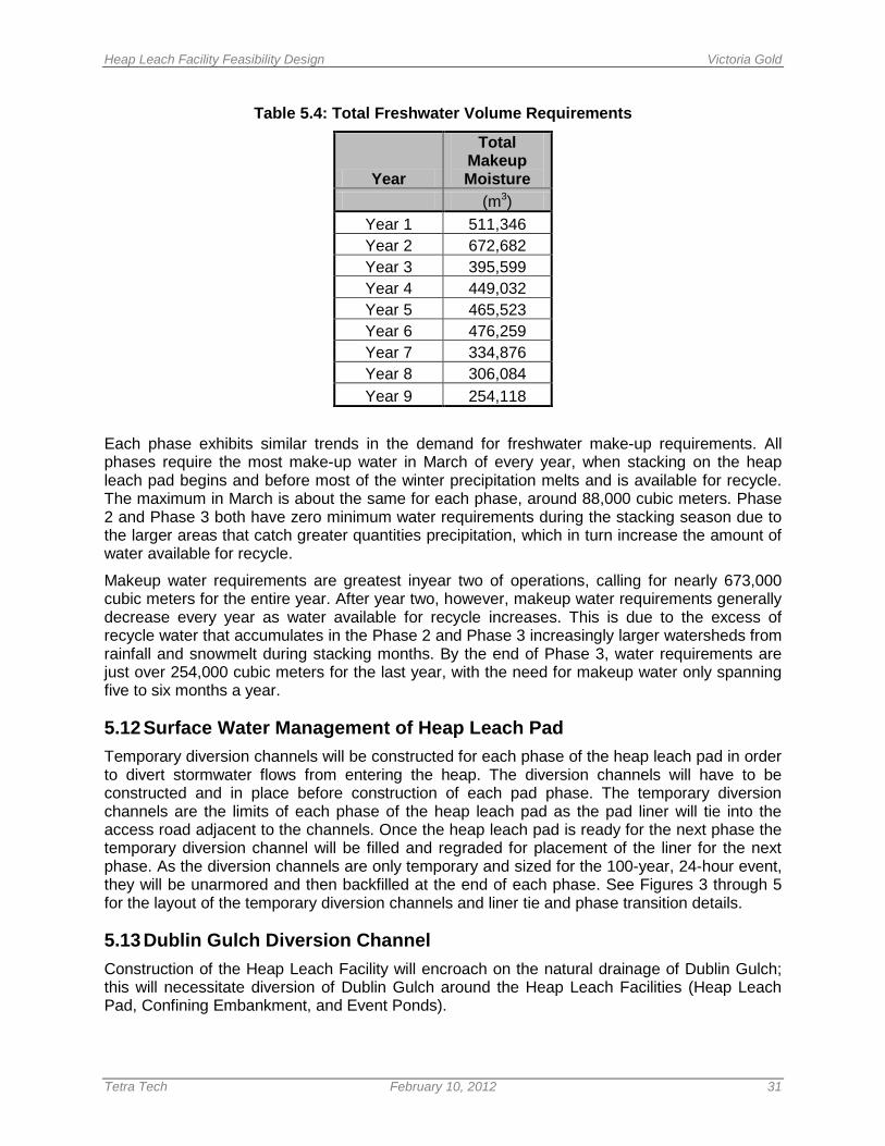
Heap Leach Facility Feasibility Design Victoria Gold
Tetra Tech February 10, 2012 31
Table 5.4: Total Freshwater Volume Requirements
Year
Total Makeup Moisture
(m3) Year 1 511,346 Year 2 672,682 Year 3 395,599 Year 4 449,032 Year 5 465,523 Year 6 476,259 Year 7 334,876 Year 8 306,084 Year 9 254,118
Each phase exhibits similar trends in the demand for freshwater make-up requirements. All phases require the most make-up water in March of every year, when stacking on the heap leach pad begins and before most of the winter precipitation melts and is available for recycle. The maximum in March is about the same for each phase, around 88,000 cubic meters. Phase 2 and Phase 3 both have zero minimum water requirements during the stacking season due to the larger areas that catch greater quantities precipitation, which in turn increase the amount of water available for recycle.
Makeup water requirements are greatest inyear two of operations, calling for nearly 673,000 cubic meters for the entire year. After year two, however, makeup water requirements generally decrease every year as water available for recycle increases. This is due to the excess of recycle water that accumulates in the Phase 2 and Phase 3 increasingly larger watersheds from rainfall and snowmelt during stacking months. By the end of Phase 3, water requirements are just over 254,000 cubic meters for the last year, with the need for makeup water only spanning five to six months a year.
5.12 Surface Water Management of Heap Leach Pad Temporary diversion channels will be constructed for each phase of the heap leach pad in order to divert stormwater flows from entering the heap. The diversion channels will have to be constructed and in place before construction of each pad phase. The temporary diversion channels are the limits of each phase of the heap leach pad as the pad liner will tie into the access road adjacent to the channels. Once the heap leach pad is ready for the next phase the temporary diversion channel will be filled and regraded for placement of the liner for the next phase. As the diversion channels are only temporary and sized for the 100-year, 24-hour event, they will be unarmored and then backfilled at the end of each phase. See Figures 3 through 5 for the layout of the temporary diversion channels and liner tie and phase transition details.
5.13 Dublin Gulch Diversion Channel Construction of the Heap Leach Facility will encroach on the natural drainage of Dublin Gulch; this will necessitate diversion of Dublin Gulch around the Heap Leach Facilities (Heap Leach Pad, Confining Embankment, and Event Ponds).

Heap Leach Facility Feasibility Design Victoria Gold
Tetra Tech February 10, 2012 32
In general, the Channel will redirect flow in Dublin Gulch to the south of the proposed Heap Leach Facility and then join with the Eagle Creek fish habitat compensation channel , which ultimately drains to Haggart Creek about 1.5 km downstream of the existing Dublin Gulch-Haggart Creek confluence (see Figures 17 through 21). The Dublin Gulch Diversion Channel is a large structure, and will consist of the following major components:
• A turf reinforced armored “upper channel reach” with a slope of 1.0%.
• A series of concrete armored stepped “drop structures”. A drop structure consists of: an approach inlet channel (1.0% slope); a drop chute channel (50.0% slope), an energy dissipation pool (0.0% slope); and an outlet channel (1.0% slope).
• A turf reinforced armored “lower channel reach” with a slope of 1.0% with intermediate drop structures.
The Channel will receive the majority of its flow at the inlet (flow from Dublin Gulch), in addition, it may also receive flow during large storm events that represents overflows from sediment control ponds that capture runoff from within the project footprint. The extent of the current design of the Dublin Gulch Diversion Channel is limited to immediately downstream of the Event Ponds. The remainder of the channel and it’s connection with the fish habitat compensation channel is subject to the final placement of facilities downstream and is to be completed by others as determined by Victoria Gold.
The diversion channel capacity and armoring is sized primarily for the 100-year, 24-hour storm event with 0.5 m of freeboard. Additionally, the channel will have the capacity to convey the 500-year, 24-hour event without freeboard. Armoring will not be sized to accommodate the 500-year event. The design of the diversion channels are presented in detail in Appendix C in the technical memorandum titled Dublin Gulch Diversion Channel Design.
5.13.1 Hydrologic Design Flows Hydrologic peak flows for the 100-year, 24-hour and 500-year, 24-hour events were calculated by Knight Piesold (2011) and are summarized in Table 5.5 below. The total design flow was used to size the entire length of the channel.
Table 5.5: Dublin Gulch Diversion Channel Design Flows
Contributing Basin/Gulch
100-year, 24-hour Design Flow (m3/s)
500-year, 24-hour Design Flow (m3/s)
Dublin Gulch 8.5 10.3 Eagle Pup Gulch 1.5 4.9
Stuttle Gulch 0.6 2.6 Total Design Flow 10.6 17.8
5.13.2 Channel Armoring Pyramat® armoring was selected to armor the 1.0% slopes of the channel. Pyramat® by Propex Geosynthetics is a three-dimensional, woven polypropylene geotextile turf reinforcement mat. When seeded properly, it allows vegetation to grow through the mat which increases its stability. As recommended by the vendor, Propex Geosynthetics would need to verify calculations and evaluate site specific applicability of Pyramat® for the channel.
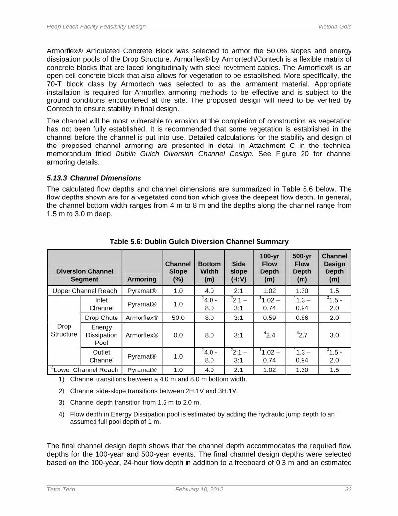
Heap Leach Facility Feasibility Design Victoria Gold
Tetra Tech February 10, 2012 33
Armorflex® Articulated Concrete Block was selected to armor the 50.0% slopes and energy dissipation pools of the Drop Structure. Armorflex® by Armortech/Contech is a flexible matrix of concrete blocks that are laced longitudinally with steel revetment cables. The Armorflex® is an open cell concrete block that also allows for vegetation to be established. More specifically, the 70-T block class by Armortech was selected to as the armament material. Appropriate installation is required for Armorflex armoring methods to be effective and is subject to the ground conditions encountered at the site. The proposed design will need to be verified by Contech to ensure stability in final design.
The channel will be most vulnerable to erosion at the completion of construction as vegetation has not been fully established. It is recommended that some vegetation is established in the channel before the channel is put into use. Detailed calculations for the stability and design of the proposed channel armoring are presented in detail in Attachment C in the technical memorandum titled Dublin Gulch Diversion Channel Design. See Figure 20 for channel armoring details.
5.13.3 Channel Dimensions The calculated flow depths and channel dimensions are summarized in Table 5.6 below. The flow depths shown are for a vegetated condition which gives the deepest flow depth. In general, the channel bottom width ranges from 4 m to 8 m and the depths along the channel range from 1.5 m to 3.0 m deep.
Table 5.6: Dublin Gulch Diversion Channel Summary
Diversion Channel Segment Armoring
Channel Slope
(%)
Bottom Width
(m)
Side slope (H:V)
100-yr Flow Depth
(m)
500-yr Flow Depth
(m)
Channel Design Depth
(m)
Upper Channel Reach Pyramat® 1.0 4.0 2:1 1.02 1.30 1.5
Drop Structure
Inlet Channel Pyramat® 1.0
14.0 - 8.0
22:1 – 3:1
11.02 – 0.74
11.3 – 0.94
31.5 - 2.0
Drop Chute Armorflex® 50.0 8.0 3:1 0.59 0.86 2.0 Energy
Dissipation Pool
Armorflex® 0.0 8.0 3:1 42.4 42.7 3.0
Outlet Channel Pyramat® 1.0
14.0 - 8.0
22:1 – 3:1
11.02 – 0.74
11.3 – 0.94
31.5 - 2.0
4Lower Channel Reach Pyramat® 1.0 4.0 2:1 1.02 1.30 1.5 1) Channel transitions between a 4.0 m and 8.0 m bottom width.
2) Channel side-slope transitions between 2H:1V and 3H:1V.
3) Channel depth transition from 1.5 m to 2.0 m.
4) Flow depth in Energy Dissipation pool is estimated by adding the hydraulic jump depth to an assumed full pool depth of 1 m.
The final channel design depth shows that the channel depth accommodates the required flow depths for the 100-year and 500-year events. The final channel design depths were selected based on the 100-year, 24-hour flow depth in addition to a freeboard of 0.3 m and an estimated
Heap Leach Facility Feasibility Design Victoria Gold
Tetra Tech February 10, 2012 34
super elevation effect of water of 0.1 m. The channel depths for the drop chute and energy dissipation pools were increased to account for increases in flow depth cause by possible air entrainment and wave action effects. These effects were only estimated for this level of design.
5.13.4 Construction Considerations Except for small fill areas along the channel, the majority of the channel was designed to be in cut in order to minimize construction complications. Final design of the Dublin Gulch Diversion Channel will include finalizing and verifying with the suppliers the selection of the proposed artificial armoring materials. This is highly dependent on soil conditions along the channel alignment.
Special construction considerations must be taken into account during construction of the diversion channel. The channel must be completed prior to construction of the Confining Embankment, Heap Leach Pad and Ponds. The entire channel must have adequate vegetation growth established prior to redirecting flows into the channel.
The final design of the channel is subject to further site investigation. The proposed armament materials and channel design are based on the available data, and additional data such as soil conditions and geology along the channel alignment are needed to finalize the design. Rock encountered along the alignment may eliminate the need for armament and can alter the geometry of the channel or drop structure design.
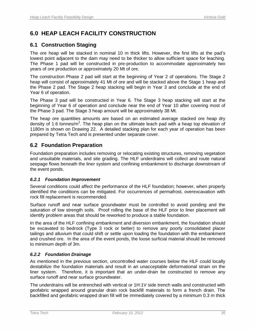
Heap Leach Facility Feasibility Design Victoria Gold
Tetra Tech February 10, 2012 35
6.0 HEAP LEACH FACILITY CONSTRUCTION
6.1 Construction Staging The ore heap will be stacked in nominal 10 m thick lifts. However, the first lifts at the pad’s lowest point adjacent to the dam may need to be thicker to allow sufficient space for leaching. The Phase 1 pad will be constructed in pre-production to accommodate approximately two years of ore production or approximately 20 Mt of ore.
The construction Phase 2 pad will start at the beginning of Year 2 of operations. The Stage 2 heap will consist of approximately 41 Mt of ore and will be stacked above the Stage 1 heap and the Phase 2 pad. The Stage 2 heap stacking will begin in Year 3 and conclude at the end of Year 6 of operation.
The Phase 3 pad will be constructed in Year 6. The Stage 3 heap stacking will start at the beginning of Year 6 of operation and conclude near the end of Year 10 after covering most of the Phase 3 pad. The Stage 3 heap amount will be approximately 38 Mt.
The heap ore quantities amounts are based on an estimated average stacked ore heap dry density of 1.6 tonnes/m3. The heap plan on the ultimate leach pad with a heap top elevation of 1180m is shown on Drawing 22. A detailed stacking plan for each year of operation has been prepared by Tetra Tech and is presented under separate cover.
6.2 Foundation Preparation Foundation preparation includes removing or relocating existing structures, removing vegetation and unsuitable materials, and site grading. The HLF underdrains will collect and route natural seepage flows beneath the liner system and confining embankment to discharge downstream of the event ponds.
6.2.1 Foundation Improvement Several conditions could affect the performance of the HLF foundation; however, when properly identified the conditions can be mitigated. For occurrences of permafrost, overexcavation with rock fill replacement is recommended.
Surface runoff and near surface groundwater must be controlled to avoid ponding and the saturation of low strength soils. Proof rolling the base of the HLF prior to liner placement will identify problem areas that should be reworked to produce a stable foundation.
In the area of the HLF confining embankment and diversion embankment, the foundation should be excavated to bedrock (Type 3 rock or better) to remove any poorly consolidated placer tailings and alluvium that could shift or settle upon loading the foundation with the embankment and crushed ore. In the area of the event ponds, the loose surficial material should be removed to minimum depth of 3m.
6.2.2 Foundation Drainage As mentioned in the previous section, uncontrolled water courses below the HLF could locally destabilize the foundation materials and result in an unacceptable deformational strain on the liner system. Therefore, it is important that an under-drain be constructed to remove any surface runoff and near surface groundwater.
The underdrains will be entrenched with vertical or 1H:1V side trench walls and constructed with geofabric wrapped around granular drain rock backfill materials to form a french drain. The backfilled and geofabric wrapped drain fill will be immediately covered by a minimum 0.3 m thick
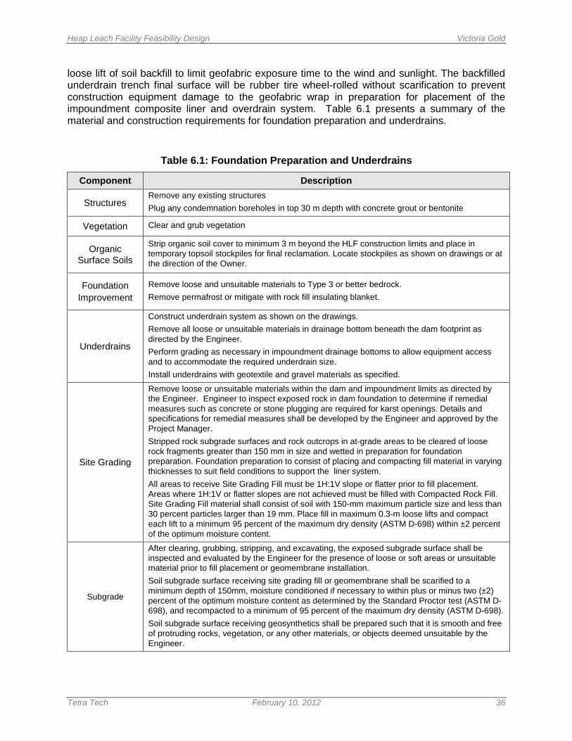
Heap Leach Facility Feasibility Design Victoria Gold
Tetra Tech February 10, 2012 36
loose lift of soil backfill to limit geofabric exposure time to the wind and sunlight. The backfilled underdrain trench final surface will be rubber tire wheel-rolled without scarification to prevent construction equipment damage to the geofabric wrap in preparation for placement of the impoundment composite liner and overdrain system. Table 6.1 presents a summary of the material and construction requirements for foundation preparation and underdrains.
Table 6.1: Foundation Preparation and Underdrains
Component Description
Structures Remove any existing structures Plug any condemnation boreholes in top 30 m depth with concrete grout or bentonite
Vegetation Clear and grub vegetation
Organic Surface Soils
Strip organic soil cover to minimum 3 m beyond the HLF construction limits and place in temporary topsoil stockpiles for final reclamation. Locate stockpiles as shown on drawings or at the direction of the Owner.
Foundation Improvement
Remove loose and unsuitable materials to Type 3 or better bedrock. Remove permafrost or mitigate with rock fill insulating blanket.
Underdrains
Construct underdrain system as shown on the drawings. Remove all loose or unsuitable materials in drainage bottom beneath the dam footprint as directed by the Engineer. Perform grading as necessary in impoundment drainage bottoms to allow equipment access and to accommodate the required underdrain size. Install underdrains with geotextile and gravel materials as specified.
Site Grading
Remove loose or unsuitable materials within the dam and impoundment limits as directed by the Engineer. Engineer to inspect exposed rock in dam foundation to determine if remedial measures such as concrete or stone plugging are required for karst openings. Details and specifications for remedial measures shall be developed by the Engineer and approved by the Project Manager. Stripped rock subgrade surfaces and rock outcrops in at-grade areas to be cleared of loose rock fragments greater than 150 mm in size and wetted in preparation for foundation preparation. Foundation preparation to consist of placing and compacting fill material in varying thicknesses to suit field conditions to support the liner system. All areas to receive Site Grading Fill must be 1H:1V slope or flatter prior to fill placement. Areas where 1H:1V or flatter slopes are not achieved must be filled with Compacted Rock Fill. Site Grading Fill material shall consist of soil with 150-mm maximum particle size and less than 30 percent particles larger than 19 mm. Place fill in maximum 0.3-m loose lifts and compact each lift to a minimum 95 percent of the maximum dry density (ASTM D-698) within ±2 percent of the optimum moisture content.
Subgrade
After clearing, grubbing, stripping, and excavating, the exposed subgrade surface shall be inspected and evaluated by the Engineer for the presence of loose or soft areas or unsuitable material prior to fill placement or geomembrane installation. Soil subgrade surface receiving site grading fill or geomembrane shall be scarified to a minimum depth of 150mm, moisture conditioned if necessary to within plus or minus two (±2) percent of the optimum moisture content as determined by the Standard Proctor test (ASTM D-698), and recompacted to a minimum of 95 percent of the maximum dry density (ASTM D-698). Soil subgrade surface receiving geosynthetics shall be prepared such that it is smooth and free of protruding rocks, vegetation, or any other materials, or objects deemed unsuitable by the Engineer.
Heap Leach Facility Feasibility Design Victoria Gold
Tetra Tech February 10, 2012 37
6.3 Dam Configuration and Zoning The embankment dam is designed as an earth fill/rock fill structure with a geomembrane lined upstream dam face and appropriate filter and transition zones to ensure containment integrity. The planned fill placement for the HLF structures includes the use of conventional earth moving equipment, water wagons, roller compactors for earth fills, and vibratory compactors for rock fills. Suitable fill materials will be produced from required excavations for the HLF structures, borrow areas and onsite mine pit excavations. Moisture conditioning will be performed as needed in the embankment fills for compaction.
The fill types include compacted rock fill material taken from selective excavations for placement in the central and downstream section of the HLF embankment. The pre-production overburden removal excavations are estimated to include sufficient quantities of materials suitable for embankment fill and site grading fills. More competent durable rock for production of required drain rock will be quarried and crushed from required site excavations and filter materials will be produced from screening of placer fill materials in the Dublin Gulch valley bottom that require excavation.
Rock fill material containing more than 30 percent of particles above 19 mm (3/4 inch) size may be considered for use as fill in areas for select applications where frost susceptibility and drainage are less important such as the HLF containment embankment and the Dublin Gulch diversion embankment.
It will likely be necessary to use relatively weak, non-durable rock for construction of rock fill in the embankments. Rock fill derived from weak rock will have high fines content, and therefore will not be suitable in applications where subsurface drainage is important, or where frost susceptibility is a concern. The construction of a rock fill developed with weak source rock will require careful quality control. The construction of a rock fill using locally derived metasediments will require the use of heavy vibratory rollers, use of thin lifts (i.e. 300 mm loose lifts) and application of water, similar to construction of an earth fill. Compaction control requirements for rock fill may be determined based on the results of a test fill. The test fill should be constructed and monitored in accordance with the U. S. Army Corps of Engineers’ (USACE) guidelines for test fill construction (USACE EM 1110-2-2301). In the event a source of higher quality rock is located capable of producing hard, durable rock particles, as expected from some of the waste rock derived from the open pit, the rock fill can be constructed in 1 m lifts and compacted by heavy construction traffic.
The rock fill specifications will require selection of competent waste rock with strength rating of R3 or harder as determined by International Society of Rock Mechanics (ISRM) procedures. Dozers will spread the dumped rock piles in controlled lifts for compaction by the loaded trucks or by large vibratory steel drum compactor rollers. The lift thickness and compactive effort for rock fill placement will be determined by the Engineer in test fills at the embankment site during startup of embankment construction and as required during construction or when material differing from the initial test materials is encountered.
The compacted earth and rock fill embankment section will use compacted rock fill materials in the compacted rock fill zone for dam slope stability. A low-permeability earth fill section will be placed in the upstream section for seepage control with filter zones to provide transition from the upstream seal zone fill to the downstream rock fill section. The dam configuration and fill descriptions are provided in Table 6.2.
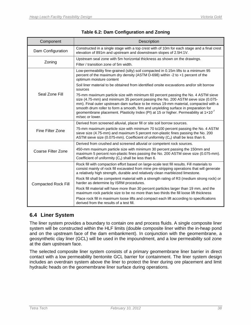
Heap Leach Facility Feasibility Design Victoria Gold
Tetra Tech February 10, 2012 38
Table 6.2: Dam Configuration and Zoning
Component Description
Dam Configuration Constructed in a single stage with a top crest with of 10m for each stage and a final crest elevation of 891m and upstream and downstream slopes of 2.5H:1V.
Zoning Upstream seal zone with 5m horizontal thickness as shown on the drawings. Filter / transition zone of 5m width.
Seal Zone Fill
Low-permeability fine-grained (silty) soil compacted in 0.15m lifts to a minimum 95 percent of the maximum dry density (ASTM D-698) within -2 to +1 percent of the optimum moisture content Soil liner material to be obtained from identified onsite excavations and/or silt borrow sources 75-mm maximum particle size with minimum 60 percent passing the No. 4 ASTM sieve size (4.75-mm) and minimum 35 percent passing the No. 200 ASTM sieve size (0.075-mm). Final outer upstream dam surface to be minus 19-mm material, compacted with a smooth drum roller to form a smooth, firm and unyielding surface in preparation for geomembrane placement. Plasticity Index (PI) at 15 or higher. Permeability at 1×10⁻⁷ m/sec or lower.
Fine Filter Zone
Derived from screened alluvial, placer fill or site soil borrow sources. 75-mm maximum particle size with minimum 70 to100 percent passing the No. 4 ASTM sieve size (4.75-mm) and maximum 5 percent non-plastic fines passing the No. 200 ASTM sieve size (0.075-mm). Coefficient of uniformity (Cu) shall be less than 6.
Coarse Filter Zone
Derived from crushed and screened alluvial or competent rock sources. 450-mm maximum particle size with minimum 30 percent passing the 150mm and maximum 5 percent non-plastic fines passing the No. 200 ASTM sieve size (0.075-mm). Coefficient of uniformity (Cu) shall be less than 6.
Compacted Rock Fill
Rock fill with compaction effort based on large-scale test fill results. Fill materials to consist mainly of rock fill excavated from mine pre-stripping operations that will generate a relatively high strength, durable and relatively clean marbleized limestone. Rock fill shall be competent material with a strength rating of R3 (medium strong rock) or harder as determine by ISRM procedures. Rock fill material will have more than 30 percent particles larger than 19 mm, and the maximum rock particle size to be no more than two thirds the fill loose lift thickness Place rock fill in maximum loose lifts and compact each lift according to specifications derived from the results of a test fill.
6.4 Liner System The liner system provides a boundary to contain ore and process fluids. A single composite liner system will be constructed within the HLF limits (double composite liner within the in-heap pond and on the upstream face of the dam embankment). In conjunction with the geomembrane, a geosynthetic clay liner (GCL) will be used in the impoundment, and a low permeability soil zone at the dam upstream face.
The selected composite liner system consists of a primary geomembrane liner barrier in direct contact with a low permeability bentonite GCL barrier for containment. The liner system design includes an overdrain system above the liner to protect the liner during ore placement and limit hydraulic heads on the geomembrane liner surface during operations.
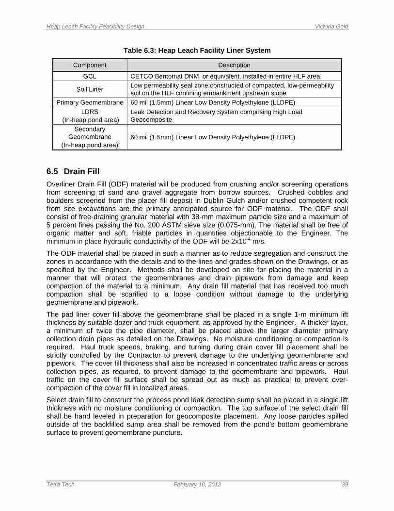
Heap Leach Facility Feasibility Design Victoria Gold
Tetra Tech February 10, 2012 39
Table 6.3: Heap Leach Facility Liner System
Component Description
GCL CETCO Bentomat DNM, or equivalent, installed in entire HLF area.
Soil Liner Low permeability seal zone constructed of compacted, low-permeability soil on the HLF confining embankment upstream slope
Primary Geomembrane 60 mil (1.5mm) Linear Low Density Polyethylene (LLDPE) LDRS
(In-heap pond area) Leak Detection and Recovery System comprising High Load Geocomposite
Secondary Geomembrane
(In-heap pond area) 60 mil (1.5mm) Linear Low Density Polyethylene (LLDPE)
6.5 Drain Fill Overliner Drain Fill (ODF) material will be produced from crushing and/or screening operations from screening of sand and gravel aggregate from borrow sources. Crushed cobbles and boulders screened from the placer fill deposit in Dublin Gulch and/or crushed competent rock from site excavations are the primary anticipated source for ODF material. The ODF shall consist of free-draining granular material with 38-mm maximum particle size and a maximum of 5 percent fines passing the No. 200 ASTM sieve size (0.075-mm). The material shall be free of organic matter and soft, friable particles in quantities objectionable to the Engineer. The minimum in place hydraulic conductivity of the ODF will be 2x10⁻⁴ m/s.
The ODF material shall be placed in such a manner as to reduce segregation and construct the zones in accordance with the details and to the lines and grades shown on the Drawings, or as specified by the Engineer. Methods shall be developed on site for placing the material in a manner that will protect the geomembranes and drain pipework from damage and keep compaction of the material to a minimum. Any drain fill material that has received too much compaction shall be scarified to a loose condition without damage to the underlying geomembrane and pipework.
The pad liner cover fill above the geomembrane shall be placed in a single 1-m minimum lift thickness by suitable dozer and truck equipment, as approved by the Engineer. A thicker layer, a minimum of twice the pipe diameter, shall be placed above the larger diameter primary collection drain pipes as detailed on the Drawings. No moisture conditioning or compaction is required. Haul truck speeds, braking, and turning during drain cover fill placement shall be strictly controlled by the Contractor to prevent damage to the underlying geomembrane and pipework. The cover fill thickness shall also be increased in concentrated traffic areas or across collection pipes, as required, to prevent damage to the geomembrane and pipework. Haul traffic on the cover fill surface shall be spread out as much as practical to prevent over-compaction of the cover fill in localized areas.
Select drain fill to construct the process pond leak detection sump shall be placed in a single lift thickness with no moisture conditioning or compaction. The top surface of the select drain fill shall be hand leveled in preparation for geocomposite placement. Any loose particles spilled outside of the backfilled sump area shall be removed from the pond’s bottom geomembrane surface to prevent geomembrane puncture.
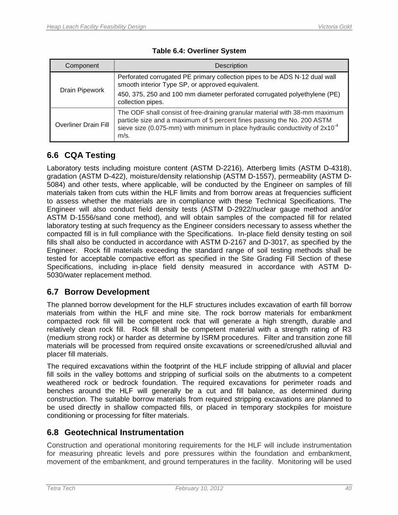
Heap Leach Facility Feasibility Design Victoria Gold
Tetra Tech February 10, 2012 40
Table 6.4: Overliner System
Component Description
Drain Pipework
Perforated corrugated PE primary collection pipes to be ADS N-12 dual wall smooth interior Type SP, or approved equivalent. 450, 375, 250 and 100 mm diameter perforated corrugated polyethylene (PE) collection pipes.
Overliner Drain Fill
The ODF shall consist of free-draining granular material with 38-mm maximum particle size and a maximum of 5 percent fines passing the No. 200 ASTM sieve size (0.075-mm) with minimum in place hydraulic conductivity of 2x10⁻⁴ m/s.
6.6 CQA Testing Laboratory tests including moisture content (ASTM D-2216), Atterberg limits (ASTM D-4318), gradation (ASTM D-422), moisture/density relationship (ASTM D-1557), permeability (ASTM D-5084) and other tests, where applicable, will be conducted by the Engineer on samples of fill materials taken from cuts within the HLF limits and from borrow areas at frequencies sufficient to assess whether the materials are in compliance with these Technical Specifications. The Engineer will also conduct field density tests (ASTM D-2922/nuclear gauge method and/or ASTM D-1556/sand cone method), and will obtain samples of the compacted fill for related laboratory testing at such frequency as the Engineer considers necessary to assess whether the compacted fill is in full compliance with the Specifications. In-place field density testing on soil fills shall also be conducted in accordance with ASTM D-2167 and D-3017, as specified by the Engineer. Rock fill materials exceeding the standard range of soil testing methods shall be tested for acceptable compactive effort as specified in the Site Grading Fill Section of these Specifications, including in-place field density measured in accordance with ASTM D-5030/water replacement method.
6.7 Borrow Development The planned borrow development for the HLF structures includes excavation of earth fill borrow materials from within the HLF and mine site. The rock borrow materials for embankment compacted rock fill will be competent rock that will generate a high strength, durable and relatively clean rock fill. Rock fill shall be competent material with a strength rating of R3 (medium strong rock) or harder as determine by ISRM procedures. Filter and transition zone fill materials will be processed from required onsite excavations or screened/crushed alluvial and placer fill materials.
The required excavations within the footprint of the HLF include stripping of alluvial and placer fill soils in the valley bottoms and stripping of surficial soils on the abutments to a competent weathered rock or bedrock foundation. The required excavations for perimeter roads and benches around the HLF will generally be a cut and fill balance, as determined during construction. The suitable borrow materials from required stripping excavations are planned to be used directly in shallow compacted fills, or placed in temporary stockpiles for moisture conditioning or processing for filter materials.
6.8 Geotechnical Instrumentation Construction and operational monitoring requirements for the HLF will include instrumentation for measuring phreatic levels and pore pressures within the foundation and embankment, movement of the embankment, and ground temperatures in the facility. Monitoring will be used
Heap Leach Facility Feasibility Design Victoria Gold
Tetra Tech February 10, 2012 41
to verify the facility components are performing as expected and to provide early warning of problematic conditions. Observations on the performance of the initial stages may provide useful information for optimizing subsequent stages of development. The following instrumentation is recommended to be installed within, and beneath the HLF:
• Vibrating Wire Piezometer: Piezometers allow measurement of water levels and pore pressures. Instruments: should be placed at strategic locations within the foundation materials, foundation drains, embankment fill materials, overliner, and at critical locations within the collection piping and sumps. These instruments will provide important information regarding pore pressures and phreatic levels in the embankment and solution levels within the heap leach ore pile.
• Slope Inclinometers: Inclinometers allow accurate measurement of ground movement and deformation. Inclinometer casings should be placed within the embankments as either construction progresses, or installed at the end of construction.
• Survey Monuments: Conventional survey monuments can installed at strategic locations for periodic survey to detect ground movement. Monuments should be installed on the finished surface of the structures, and potentially on select areas of the stacked ore.
• Thermistors: Thermistors are electronic instruments used to measure ground temperature. Instruments should be placed beneath the heap leach pad and embankments. Measurements will be used in assessing changes to frozen ground and permafrost conditions beneath the HLF, and the resulting impact to geotechnical stability and groundwater seepage conditions.
• Flow Meters: Flow meters are used to measure flow volume and velocity in pipes. Instruments should be installed at the outlets of the LDRS. The flow meters will provide a measure of leakage through the liner. Flow meters may also be installed at the outlets of the foundation drains in order to monitor the flow of water out of the foundations, which coupled with the temperature data may give some indication of settlement that is occurring beneath the base of the heap.
Heap Leach Facility Feasibility Design Victoria Gold
Tetra Tech February 10, 2012 42
7.0 HEAP LEACH OPERATIONS
7.1 General Ore will be crushed year round (350 days) at a nominal rate of 29,500 dry t/d. Ore placement on the HLF will occur over a 250 day period at a rate of 41,300 tpd and stored on a 100-day stockpile during the coldest time of the year (November to March). The HLF will be loaded using a grasshopper conveyor system that will run down a lined corridor in the initial phase of loading with a stacker. Ore will be stacked at an overall slope of 2.5:1 (H:V) with benches between angle of repose lifts. The ore heap will be stacked in nominal 10 m thick lifts. However, the first lifts at the pad’s lowest point adjacent to the dam may need to be thicker to allow sufficient space for leaching. Loading will begin at the toe of the embankment and progressively work upgradient and will alternate to permit sufficient time for leaching prior to placement of subsequent overlying lifts of ore. Drip emitters will be trenched into the top layer of the heap. Solution will be applied at an approximate irrigation rate of 2,770 m3/hour over an approximate area of 277,000 m2 for a planned leaching cycle estimated at 150 days. Proposed heap leach operations will involve crushing and stacking 10 Mt of ore during 250 days per year with ore leaching year-round with three active leach areas being leached in the winter months. The ore placement will be ahead of the active leaching areas during summer operations, then the emitters will be buried at the start of winter for frost protection and leaching will continue to "catch up" with the ore placement. A narrow ore bench (10 m wide) will be constructed at 888.5 m elevation adjacent to the HLF confining embankment crest for stormwater collection and conveyance of flows to the spillway which has an invert elevation of 889 m. In the event of an emergency or other unforeseen circumstance in which pumping of solution ceases, or in the event of excessive surface runoff from the heap leach pad, discharge of excess water or solution will be directed in a controlled manner through a lined spillway to the Events Pond. Solution levels within the heap are expected to be kept low during normal operations. However, during emergency situations, the lined spillway will prevent overtopping of the embankment, and will maintain containment of the solution at all times. Prior to operating the HLF, a Heap Leach Facility Operating Plan will be developed to set out procedures which are designed to ensure that all liquids are accounted for in the operation of the mine.
7.2 Cold Weather Considerations The Eagle Gold site is located in the Yukon where winter air temperatures can reach minus 35 degrees Celsius or colder in the winter months. A cursory review and comparison of heap leaching operations in cold climates indicates year-round leaching operations at Eagle Gold are considered feasible assuming design provisions are incorporated for adding and maintaining heat in the process solutions applied to the heap and proper operational provisions are incorporated. Operations in Alaska and northwest Canada include Fort Knox in Central Alaska, and Brewery Creek in Central Yukon. Table 7.1 compares minimum air temperatures for Brewery Creek, where heap leaching has been successful.
The Brewery Creek mine is in a climate with low temperatures to minus 40 C and utilized “in-heap” solution storage with no “open” process ponds, heated barren solutions, heat-traced and insulated barren tanks and pipelines, and buried emitters. Heap leach operations in this type of climate can be leached year-round with seasonal stacking (stockpiling and rehandling) due to the presence of frozen material on the heap leach during cold months. Frozen ore on a heap
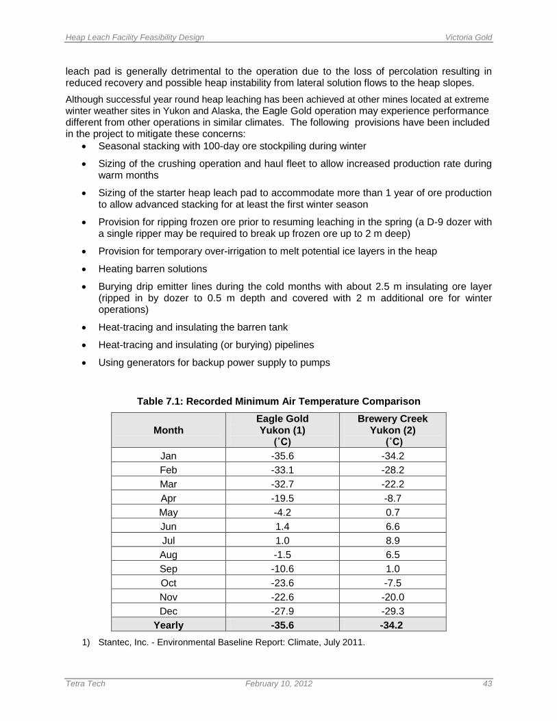
Heap Leach Facility Feasibility Design Victoria Gold
Tetra Tech February 10, 2012 43
leach pad is generally detrimental to the operation due to the loss of percolation resulting in reduced recovery and possible heap instability from lateral solution flows to the heap slopes. Although successful year round heap leaching has been achieved at other mines located at extreme winter weather sites in Yukon and Alaska, the Eagle Gold operation may experience performance different from other operations in similar climates. The following provisions have been included in the project to mitigate these concerns:
• Seasonal stacking with 100-day ore stockpiling during winter
• Sizing of the crushing operation and haul fleet to allow increased production rate during warm months
• Sizing of the starter heap leach pad to accommodate more than 1 year of ore production to allow advanced stacking for at least the first winter season
• Provision for ripping frozen ore prior to resuming leaching in the spring (a D-9 dozer with a single ripper may be required to break up frozen ore up to 2 m deep)
• Provision for temporary over-irrigation to melt potential ice layers in the heap
• Heating barren solutions
• Burying drip emitter lines during the cold months with about 2.5 m insulating ore layer (ripped in by dozer to 0.5 m depth and covered with 2 m additional ore for winter operations)
• Heat-tracing and insulating the barren tank
• Heat-tracing and insulating (or burying) pipelines
• Using generators for backup power supply to pumps
Table 7.1: Recorded Minimum Air Temperature Comparison
Month
Eagle Gold Yukon (1)
(˚C)
Brewery Creek Yukon (2)
(˚C) Jan -35.6 -34.2 Feb -33.1 -28.2 Mar -32.7 -22.2 Apr -19.5 -8.7 May -4.2 0.7 Jun 1.4 6.6 Jul 1.0 8.9 Aug -1.5 6.5 Sep -10.6 1.0 Oct -23.6 -7.5 Nov -22.6 -20.0 Dec -27.9 -29.3
Yearly -35.6 -34.2 1) Stantec, Inc. - Environmental Baseline Report: Climate, July 2011.
Heap Leach Facility Feasibility Design Victoria Gold
Tetra Tech February 10, 2012 44
2) Harper, Thomas, et.al., “Heap Leaching in Extreme Northern Climates, An Overview of the Brewery Creek Mine, Yukon, Canada”
7.3 Solution Delivery System The process pumping system will include pumps, pipelines, valves, and associated controls to move solutions between the plant and the heap leach facilities. The process pumping and solution delivery systems should include necessary provisions for frost protection including:
• Heated barren solutions
• Buried emitters (ripped in by dozer to 0.5m depth and covered with 2m additional ore is recommended for winter operations).
• Heat traced and insulated barren tank
• Heat traced and insulated (or buried) pipelines as needed
• Backup power supply to pumps via generators
• Provisions for pipeline draindown upon shutdown

Heap Leach Facility Feasibility Design Victoria Gold
Tetra Tech February 10, 2012 45
8.0 MATERIAL QUANTITIES
The material quantities for the construction of the Eagle Gold HLF phases including earthwork, geosynthetics and piping are presented in the table included in Appendix E. Material shrinkage or bulking was not considered in calculating the earthwork cut and fill quantities. A seven percent factor has been added to the geosynthetics take-offs for overlap and waste.
Heap Leach Facility Feasibility Design Victoria Gold
Tetra Tech February 10, 2012 46
9.0 GENERAL INFORMATION
The project site information and characteristics was provided by various consultants as referenced and acknowledged herein.
9.1 Applicability This report entitled “Eagle Gold Project, Heap Leach Facility Feasibility Design Report” has been prepared for the exclusive use of Victoria Gold for purposes of assessing the scope, feasibility and cost of heap leaching operations for the Project. No other parties shall be entitled to use this report without the written consent of Victoria Gold and Tetra Tech. The use of this report and information contained herein shall be at the sole risk of the user regardless of any fault or negligence of Victoria Gold or Tetra Tech. The design, construction methodologies and operating procedures described in the report are also intended to assist others in assessing environmental impacts of the project and to serve as supporting documentation for permitting by regulatory agencies.
9.2 Acknowledgement of Key Internal Participants The project engineering analyses and designs were conducted by several Tetra Tech staff members under the guidance of Mr. Troy Meyer, P.Eng., Geotechnical Engineer and Project Manager. Mr. David Hallman, P.E. provided input on the seismicity.
9.3 Quality Statement and Affirmation of Limitations This work has been completed to the level of detail and within the limits presented in this report. To the best of our knowledge, the information presented in this report is accurate to the limits specified herein. The material in the report reflects Tetra Tech’s best judgment in the light of information available to us at the time of preparation. Our services were performed in a prudent and diligent manner using reasonable skill, care, modern techniques and sound professional practice and standards.
Heap Leach Facility Feasibility Design Victoria Gold
Tetra Tech February 10, 2012 47
10.0 REFERENCES
British Columbia Mine Waste Rock Pile Research Committee (1991), Mined Rock and Overburden Piles Investigation and Design Manual
Canadian Dam Association (2007), Dam Safety Guidelines. Edmonton, Alberta, Canada.
GEO-SLOPE International, Ltd. (2004), User’s Guide – Slope\W for Slope Stability Analysis – Version 4, Calgary, Alberta, Canada.
Knight Piesold Ltd., Aurala, C. (2011). Email Correspondence Subject: Eagle Gold Design Precipitation Events. Email dated July 4, 2011.Spencer, E. (1967), A Method of Analysis of the Stability of Embankments Assuming Parallel Inter-Slice Forces. Geotechnique, Vol. 17, No. 1, pp. 11-26.
Stantec (2011), Eagle Gold Project, Environmental Baseline Report: Climate, prepared for Victoria Gold Corp., July 2011.
LaGatta, M. D., Boardman, B. T., Cooley, B. H. and Daniel, D. E. (1997), Geosynthetic Clay Liners Subjected to Differential Settlement. J. Geotech. Geoenv. Eng. 123(5), pp 402-411.
Leps, T. M. (1970), Review of shearing Strength of Rockfill. J. Soil Mechanics and Foundation Division Proceedings of the American Society of Civil Engineers.
Mining Association of Canada (1998), A Guide to the Management of Tailings Facilities. Ottowa, Ontario, Canada.
National Research Council Institute for Research in Construction (2005), National Building Code of Canada
Yukon Water Board (2009), Licensing Guidelines for Type A Quartz Mining Undertakings