Embed Size (px)
Citation preview
For queries on the status of this document contact [email protected] or telephone 029 2031 5512
October 2013
HEALTH TECHNICAL MEMORANDUM 2030
Washer disinfectors: Validation and verification
1997
STATUS IN WALES
ARCHIVED
This document was superseded by
Welsh Health Technical Memorandum 01-01 Decontamination of medical devices within acute
services
2013
Washer-disinfectors
Validation and verification
Health Technical Memorandum 2030
London: The Stationery Office
© Crown copyright 1997. Published with permission of NHS Estates, an Executive Agency of the Department of Health, on behalf of the Controller of Her Majesty’s Stationery Office.
Applications for reproduction should be made in writing to The Copyright Unit, Her Majesty’s Stationery Office, St Clements House, 2–16 Colegate, Norwich NR3 1BQ.
First published 1997
ISBN 0-11-322071-5
Standing order service
Are you making full use of The Stationery Office’sStanding Order Service?
The Standing Order Service is a free monitoring of thepublications of your choice from over 4000 classificationsin 30 major subject areas. We send you your books as theyare published, along with an invoice.
With a standing order for class 14.02.017 you can besupplied automatically with further titles in this series asthey are published.
The benefits to you are:
• automatic supply of your choice of classification onpublication;
• no need for time-consuming and costly research,telephone calls and scanning of daily publicationlists;
• saving on the need and the costs of placingindividual orders.
We can supply a wide range of publications on standingorder, from individual annual publications to allpublications on a selected subject. If you do not alreadyuse this free service, or think you are not using it to its full capacity, why not contact us and discuss yourrequirements?
You can contact us at:
The Stationery OfficeStanding Order DepartmentPO Box 276London SW8 5DT
Tel: 0171-873 8466; fax 0171-873 8222
We look forward to hearing from you.
Health Technical Memoranda (HTMs)
give comprehensive advice and
guidance on the design, installation and
operation of specialised building and
engineering technology used for the
delivery of healthcare.
They are applicable to new and existing
sites, and are for use at various stages
during the inception, design,
construction, refurbishment and
maintenance of a building.
Health Technical Memorandum 2030 is
being published in three volumes.
Operational management is a
summary of the information required by
personnel responsible for the
management of facilities in which
washer-disinfectors are used. It discusses
the various types of washer-disinfectors,
for both clinical and laboratory use, and
also contains guidance on legal and
policy matters, and on the appointment
and responsibilities of personnel. It
covers all aspects of routine operation
and maintenance stressing the need for
a planned maintenance programme
along with the type of records to be
kept. Advice on the safe and efficient
operation of washer-disinfectors is
given, as well as procedures for
reporting defects and accidents. It
should be read by anyone consulting
this memorandum for the first time;
Design considerations contains
information relevant to the specification
and installation of new washer-
disinfectors. It discusses the
requirements for each type of washer-
disinfector and outlines the
specifications to be included in any
contract. Practical considerations for the
installation of washer-disinfectors are
discussed including siting, heat
emission, ventilation, noise and
vibration, and mains services with an
emphasis on steam quality;
Validation and verification covers all
aspects of validation and periodic
testing of washer-disinfectors. It includes
detailed schedules and procedures for
tests and checks to be carried out for
commissioning and performance
qualification and for subsequent
periodic testing.
About this publication
Executive summary
HTM 2030 gives guidance on the choice, specification,purchase, installation, validation, periodic testing,operation and maintenance of washer disinfectors (WDs)in use in the National Health Service for processingmedical devices, laboratory ware and sanitary products.No guidance is given on WDs intended for use inprocessing textiles or for dishwashers in general cateringapplications.
This volume is intended as a guide for technical personnelwith appropriate training and experience and also forusers responsible for the day to day running of WDs. Itwill also be of interest to architects, planners, estatesmanagers, supplies officers, and others in both the publicand private sectors.
Detailed information on the planning and design of asterile services department, including the provision ofWDs, is given in Health Building Note 13 – ‘Sterile servicesdepartment’. (Scottish Hospital Planning Note 13 appliesto the NHS in Scotland.) Guidance for laboratoryinstallations can be found in Health Building Note 15 –‘Accommodation for pathology services’ (Scottish HospitalPlanning Note 15 applies to the NHS in Scotland).
Although this edition of HTM 2030 reflects current WDtechnology it is recognised that considerable scope existsfor improvements in the operational and managementtechnology used with WDs.
The current British Standards for WDs, although only inforce since 1993, are expected to be replaced byEuropean Standards within the next two to three years.These Standards include consideration of the requirementsarising as a result of European Union Directives on medicaldevices which are of concern for WDs in two ways; firstly,some WDs will themselves be considered to be medicaldevices and therefore must meet the relevantrequirements of the Medical Devices Directive andsecondly, the manufacturer of a medical device which isintended to be reprocessed is required to specify themethod to be used for reprocessing which will include anynecessary washing and disinfecting stage.
When practicable the information in this HTM has beenaligned with existing or anticipated Standards and adviceis offered when no standard has yet been formulated.
The WDs described in this HTM may not be suitable,without modification, for safely processing articlescontaminated with either Hazard Group 4 pathogens orwith agents which are unusually resistant to disinfection.
The guidance previously given in ‘Management policy’ hasbeen incorporated into ‘Operational management’.
1
About this publication
Executive summary
1.0 General page 51.1 Introduction1.4 Legal framework for washing and disinfection
1.7 Medicinal products1.11 Medicinal devices
1.16 Published Standards1.22 Personnel1.39 Water supply1.40 Safety
1.41 Chemical additives1.45 Infectious materials
2.0 Testing of washer-disinfectors page 102.1 Introduction2.11 Responsibilities
2.12 Purchaser2.16 Manufacturer2.18 Contractor
2.20 Validation 2.21 Works test2.24 Commissioning
2.26 Installation tests2.31 Operational tests
2.33 Performance qualification2.36 Documentation
2.37 Summary sheets2.40 Validation reports
2.46 Periodic tests2.50 Revalidation2.53 Repeat validation2.56 Types of test2.58 Procedure on failure of a test2.63 Inter-relationship of test programmes
3.0 Schedule of type tests and works testspage 193.1 Introduction
Table 1: Summary of manufacturer’s testprogrammes for WDs
4.0 Schedule of installation tests page 214.1 Introduction4.6 Checks on ancillary equipment
4.9 Engineering services4.10 Additional checks for WDs using a chemical
disinfectant4.14 Checks on the WD
4.14 Preliminary checks4.16 Functional checks4.18 Response to external faults
5.0 Schedule of operational tests page 255.1 Introduction
Table 2a: WDs for human-waste containersTable 2b: WDs for surgical instrumentsTable 2c: WDs for hollowwareTable 2d: WDs for anaesthetic accessoriesTable 2e: WDs for endoscopesTable 2f: WDs for laboratory useTable 2g: Ultrasonic cleaners
6.0 Schedule of performance qualification testspage 336.1 Introduction6.14 Loading conditions6.19 Surrogate devices6.24 Cleaning efficacy tests
6.24 Native soiling6.29 Test soils6.34 Standard test soils6.36 Process residues
6.40 Disinfection6.40 Thermometric tests6.42 Microbiological testsTable 3: Thermal disinfection temperature bands
6.44 Load dryness tests6.46 PQ report
6.49 Master Process Record6.54 Tests for performance requalification
Table 4a: WDs for human-waste containersTable 4b: WDs for surgical instrumentsTable 4c: WDs for hollowwareTable 4d WDs for anaesthetic accessoriesTable 4e: WDs for endoscopesTable 4f: WDs for laboratory useTable 4g: Ultrasonic cleaners
7.1 Introduction page 427.8 Weekly safety checks7.10 Yearly safety checks
Table 5a: WDs for human-waste containersTable 5b: WDs for surgical instrumentsTable 5c: WDs for hollowwareTable 5d WDs for anaesthetic accessoriesTable 5e: WDs for endoscopesTable 5f: WDs for laboratory useTable 5g: Ultrasonic cleaners
Contents
8.0 Test equipment and materials page 538.1 Introduction8.6 Calibration and sources of error8.11 Recorders8.18 Temperature measurement
8.18 Temperature sensors8.21 Thermometric recording instrument(s)8.26 Use of sensors8.31 Calibration8.35 Self-contained systems
8.42 Pressure measurement8.43 Transducers8.44 GaugesTable 6: Requirements for pressure measurement
8.50 Flow measurement8.50 Water8.55 Chemical additives
8.61 Volume measurement8.66 Humidity measurement8.68 Other instruments
8.68 Sound level meter8.69 Balance8.71 Gas monitoring equipment8.74 Aerosol generator8.76 Particle counting photometerTable 7: Particle size distribution for aerosolgenerator
9.0 Testing methods page 649.2 Terminology
9.3 Cycle variables9.8 Disinfection conditions
9.17 Drainage9.17 Drain seal integrity9.25 Blocked drain protection9.38 Free draining9.40 Purging of the trap9.43 Efficacy of discharge through the trap9.49 Estimation of dead volume of pipework
9.57 Venting system9.57 Steam venting9.61 Load contamination from ductwork
9.69 Water system9.89 Water supply temperature9.94 Water supply pressure9.100 Appearance9.106 pH9.112 Electrical conductivity9.123 Total dissolved solids9.140 Hardness9.153 Chloride9.164 Heavy metals9.167 Iron9.176 Phosphate9.188 Silicate9.201 Bacterial endotoxins9.213 Total viable count9.227 Environmental mycobacteria
9.237 Overflow test9.245 Volume of water used per stage
9.253 Doors and door interlocks9.253 Cycle start interlock9.257 In-cycle interlock9.260 Double ended WDs9.264 On sensor failure9.266 Door opening force9.271 Failed cycle interlock9.274 Fault indication on sensor failure
9.279 Chemical dosing9.279 Reproducibility of volume admitted9.285 Indication of insufficient chemical additives
9.290 Emissions9.290 Water vapour emission9.298 Aerosol emissions9.308 Chemical vapour emission
9.311 Instrumentation fitted to WD9.313 Load carriers9.316 Thermometric tests
9.317 Chamber wall temperature9.323 Load carrier temperature9.330 Over-temperature cut-out
9.336 Load dryness9.343 Residual chemical additives9.349 Air quality9.353 Sound pressure test9.360 Electromagnetic compatibility
10.0 Cleaning efficacy tests page 10610.1 Introduction10.2 Type tests10.7 Operational tests
10.9 Test soil10.14 Test loads10.16 Procedure for chamber walls and load
carriers10.20 Procedure for reference loads10.23 Results
10.25 Performance qualification tests10.37 Periodic tests
10.37 Tests for residual soil: the ninhydrin method10.50 Visual inspection
11.0 Disinfection efficacy tests page 11211.1 Introduction11.2 Test for thermal disinfection11.4 Thermometric test for disinfection11.12 Microbiological test for performance qualification
12.0 Automatic control test page 11912.1 Introduction12.4 Test procedure
13.0 Specific tests for WDs for human-wastecontainers page 12113.1 Introduction13.4 Test for flushing of toilet tissues
2
Contents
13.15 Test for flushing of non-absorbent materials13.21 Test for safety of loading and/or emptying of
containers13.26 Reference test loads13.29 Test soil
13.29 Bedpan soil13.36 Urine bottle soil
13.43 Performance qualification tests
14.0 Specific tests for WDs for surgical instrumentspage 12714.1 Introduction14.5 Water quality14.8 Reference test loads14.12 Test soil14.19 Performance qualification tests
15.0 Specific tests for WDs for hollowwarepage 13015.1 Introduction15.4 Reference test loads15.6 Test soil15.13 Performance qualification tests
16.0 Specific tests for WDs for anaestheticaccessories page 13316.1 Introduction16.5 Reference test loads16.6 Test soil16.14 Performance qualification tests
17.0 Specific tests for Wds for endoscopespage 13617.1 Introduction17.3 WD self-disinfection test17.16 Final rinse decontamination test17.19 Channel patency detection test17.23 Disinfectant concentration test17.33 Reference test loads17.34 Test soil17.41 Microbiological test of disinfection efficacy17.43 Performance qualification tests
18.0 Specific tests for WDs for laboratory usepage 14318.1 Introduction18.3 Reference test loads18.4 Test soil18.11 Performance qualification tests
19.0 Specific tests for ultrasonic cleaners page 14519.1 Introduction19.3 Test for ultrasonic activity19.18 Reference test loads19.22 Test soil19.29 Performance qualification tests
Appendix I: Glossary page 149
Appendix II: Abbreviations page 152
Appendix III: Useful addresses page 154
References page 156
About NHS Estates page 163
3
Contents
5
Introduction
1.1 This volume of HTM 2030 covers the validation and periodic testing ofthe various types of washer disinfectors (WDs) used in hospitals, laboratoriesand other healthcare facilities.
1.2 Terminology used in washing and disinfection has long beeninconsistent and this has often led to ambiguities. This HTM introduces a setof terms which, it is hoped, will provide workers in the field with a vocabularythat will be consistent with the European Union (EU) Standards that are to beintroduced in the near future. The glossary provides a definition of termsreferred to in this volume of HTM 2030.
1.3 References for all the documents referred to in this volume and otherselected documents that provide additional information of which the readershould be aware are contained at the end of this volume.
Legal framework for washing and disinfection
1.4 WDs are used in relation to both medical devices and medicinalproducts as well as for sanitary equipment, laboratory equipment andcutlery/crockery.
1.5 They may be used for reprocessing, within their intended use, medicaldevices, sanitary equipment, laboratory equipment, manufacturing equipment(for use in the manufacture of medicinal products or medical devices) orcutlery and crockery.
1.6 They may also be used as part of the manufacturing process formedical devices, medicinal products, in vitro diagnostics or laboratory productsin processing ‘single-use’ products or components such as bottles and vials.
Medicinal products
1.7 The manufacture and supply of medicinal products are controlled byextensive legislation based on EU Directives on medicinal products andenacted in the UK by the Medicines Act and a number of Regulations.
1.8 The requirements for the manufacture and supply of medicinalproducts are set out in the ‘Guide to good manufacturing practice formedicinal products’ (GGMP) published in Volume IV of ‘The rules governingmedicinal products in the European Community’.
1.9 The GGMP contains guidance on cleaning of components andmanufacturing equipment which have implications for the design, installationand operation of WDs. When a WD is to be installed for processingcontainers, components or manufacturing equipment for use with medicinalproducts the GGMP should be consulted at an early stage.
1.0 General
1.10 Guidance on the application of medicines legislation to particular casesis beyond the scope of this HTM and advice should be sought from theMedicines Control Agency (MCA) when necessary.
Medical devices
1.11 HTM 2030 ‘Operational management’ refers to the three EuropeanDirectives on the manufacture and supply of medical devices and in vitrodiagnostics.
1.12 Whether, and if so under what circumstances, the Medical DevicesDirective applies to medical devices which are being reprocessed for furtheruse, either within a particular healthcare facility or externally under a servicecontract, is a complex issue beyond the scope of this HTM. If necessary, furtherguidance is given in the MDA Directives Bulletin 18.
1.13 The essential requirements of the Medical Devices Directive require,inter alia:
• that devices and manufacturing processes be designed to eliminate orreduce as far as possible the risk of infection to the patient, user andthird parties (Annex I, paragraph 8.1)
• that devices must be designed manufactured and packed in such a wayas to minimise the risk posed by contaminants and residues to thepersons involved in the transport, storage and use of the devices and tothe patients (Annex I, paragraph 7.2)
1.14 There is no direct equivalent of the GGMP for medical devices. Thesame role is fulfilled by general Quality System Standards (the BS EN ISO 9000series), supplemented by Standards tailoring the requirements specified in thegeneral standard for medical devices (BS EN 46001 and BS EN 46002) andStandards providing guidance on compliance with these Standards (EN 724and EN 50103).
1.15 These are mandated Standards and as such compliance with themaffords the presumption of conformance with the relevant essentialrequirements of the Directive.
Published Standards
1.16 British Standard 2745: 1993 specifies requirements for WDs for medicalpurposes. The standard is in 3 parts; Part 1 ‘Specification for GeneralRequirements’, Part 2 ‘Specification for washer-disinfectors for human-wastecontainers’ and Part 3 ‘Specification for washer-disinfectors except those usedfor processing human-waste containers and laundry’.
1.17 There are no European Standards, as yet, for WDs. CEN TechnicalCommittee TC102 is developing a series of mandated Standards relevant tothe Medical Devices Directive for WDs. There are four parts with the workingtitles ‘General Requirements’, ‘Washer-disinfectors for human-wastecontainers’, ‘Washer-disinfectors for medical devices and surgical instruments’and ‘Washer-disinfectors for thermolabile medical devices (for exampleendoscopes)’.
1.18 IEC Technical Committee TC66 is developing Standards for ‘Safetyrequirements for washer-disinfectors’.
6
1.0 General
1.19 When published, compliance with these Standards may be used togive a presumption of conformance to the relevant requirements of theMedical Devices Directive.
1.20 This edition of HTM 2030 has been written while the new Standardsare in the course of development. The guidance given here is designed to bebroadly consistent with the emerging Standards but HTM 2030 should not beregarded as a substitute for the Standards themselves when ascertainingcompliance with the EU Directives and the UK Regulations that implementthem.
1.21 If the WD is purchased with the intention of processing both medicaldevices and components, or equipment for use in the manufacture of medicalproducts, purchasers should ensure that the requirements for both types ofload are met.
Personnel
1.22 The following personnel are referred to in this volume of HTM 2030.Further information, including qualifications and areas of responsibility, can befound in HTM 2030 ‘Operational management’ and in Part 1 of HTM 2010.
1.23 Management is defined as the owner, occupier, employer, generalmanager, chief executive or other person of similar authority who is ultimatelyaccountable for the operation of the premises. Depending on the nature ofthe organisation, this role may be filled by the general manager, chiefexecutive, laboratory director or other person of similar authority. In smallautonomous units the user may take on this function.
1.24 The User is defined as the person designated by management to beresponsible for the management of the WD. In a hospital the user could be asterile services manager, theatre manager, endoscopy clinic manager, wardmanager or laboratory manager; in primary care he or she could be a generalpractitioner, dentist or other health professional. When a WD is used toprocess equipment or containers for use in the preparation of medicinalproducts the user is normally the production manager in charge of themanufacturing process.
1.25 The Competent Person (Pressure Vessels) is defined as a person ororganisation designated by management to exercise certain legalresponsibilities with regard to the written scheme of examination of anypressure vessel associated with a WD described in the ‘Pressure Systems andTransportable Gas Containers Regulations 1989’. The shorter term ‘competentperson’ is used in this HTM.
1.26 The Authorised Person (Sterilizers) is defined as a persondesignated by management to provide independent auditing and advice onsterilizers and sterilization and to review and witness validation. (see HTM2010 Part 1 for a full definition of the responsibilities of the Authorised Person(Sterilizers) with respect to sterilizers and the qualifications and experiencerequired). Authorised Persons (Sterilizers) are also able to provide independentauditing and advice on washing and disinfection and WDs and to review andwitness validation of these processes and machines. The abbreviation AP(S) isused in this HTM.
A list of suitably qualifiedauthorised persons is maintainedby the Institute of HealthcareEngineering and EstatesManagement.
‘The Pressure Systems andTransportable Gas ContainersRegulations (Northern Ireland)1991’ apply to Northern Ireland.
7
1.0 General
1.27 At the discretion of management the function of the AP(S) may becarried out by an independent person, not registered as an AP(S), but who candemonstrate, to the satisfaction of management, previous training andexperience appropriate to carry out the designated tasks in respect of WDs.
1.28 The Test Person (Sterilizers) is defined as a person designated bymanagement to carry out validation and periodic testing of sterilizers. (seeHTM 2010 Part 1 for a full definition of the responsibilities of the Test Person(Sterilizers) with respect to sterilizers and the qualification and experiencerequired). Test Persons (Sterilizers) who have received appropriate trainingshould be designated to carry out validation and periodic testing of WDs. Theabbreviation TP(S) is used in this HTM.
1.29 The Maintenance Person (Sterilizers) is defined as a persondesignated by management to carry out maintenance and periodic testing onsterilizers. (see HTM 2010 Part 1 for a full definition of the responsibilities ofthe Maintenance Person (Sterilizers) with respect to sterilizers and thequalifications and experience required). Maintenance Persons (Sterilizers) whohave received appropriate training should be designated to carry out validationand periodic testing of WDs. The abbreviation MP(S) is used in this HTM.
1.30 The Microbiologist (Sterilizers) is defined as a person designated bymanagement to be responsible for advising the user on microbiological aspectsof the sterilization of non-medicinal products. They should also be defined asthe persons responsible for advising the user on the microbiological aspects ofhandling, washing and disinfecting used medical devices. The shorter term‘microbiologist’ is used in this HTM.
1.31 The Control of Infection Officer is defined as the person designatedby management to be responsible for advising the user on all infection controlaspects.
1.32 The Production Manager is defined as a person designated bymanagement to be responsible for the production of medicinal products ormedical devices.
1.33 The Quality Controller is defined as a person designated bymanagement to be responsible for quality control of medicinal products and/ormedical devices with the authority to establish, verify and implement all qualitycontrol and quality assurance procedures.
1.34 The Laboratory Safety Officer is defined as a person designated bymanagement to be responsible for all aspects of laboratory safety includingequipment, personnel and training relating to safety matters, and ensuringcompliance with safety legislation and guidelines.
1.35 An Operator is defined as any person with the authority to operate aWD. Their duties may include the noting of WD instrument readings,replenishment of consumable items such as detergent, and simplehousekeeping duties.
1.36 The Manufacturer is defined as the person or organisation responsiblefor the manufacture of a WD.
1.37 The Contractor is defined as a person or organisation designated bymanagement to be responsible for the supply and installation of the WD, andfor carrying out the installation checks and tests. The contractor is usually themanufacturer of the WD.
8
1.0 General
1.38 The Purchaser is defined as the person or organisation who orders theWD and is responsible or paying for it.
Water supply
1.39 All the organisations responsible for water supply have the statutorypower to make and enforce byelaws to prevent waste, excessive consumption,misuse or contamination of the water supply. The Model Water Byelaws formthe basis of such byelaws. WDs must be designed, constructed, installed,operated and maintained in accordance with the requirements of the relevantbyelaws.
Safety
1.40 Guidance on the safe operation of the various types of WD is given inHTM 2030 ‘Operational management’. As far as testing is concerned, normalsafety precautions are adequate except in the case of WDs using liquidchemical germicides. In this case users are recommended to operate a permit-to-work system to ensure that such WDs are declared safe to work on, andthat personnel working on them have documented authority to do so.
Chemical additives
1.41 Many of the chemical additives used in WDs and their associatedancillary equipment, for example water treatment plant, are corrosive, toxic orotherwise hazardous and require special provision for their storage and use.
1.42 The ‘Control of Substances Hazardous to Health (COSHH) Regulations’place upon management an obligation to ensure that suitable measures areadopted to protect their staff and others affected by the work activity. Thesemethods may include both safe systems of work and the provision of a specialventilation system.
1.43 Some of the substances which may be used in WDs, in particular thoseemploying chemical disinfection or sterilization, have Occupational ExposureLimits (OEL) set out in Guidance Note EH40 published annually by the Healthand Safety Executive. These limits are statutory maxima but should not beregarded as representing a safe working exposure. Employers have a legalobligation to ensure that exposure is reduced as far as reasonably practicable.
1.44 The WD, including any special ventilation equipment necessary for itssafe operation will be subject to the COSHH Regulations. These Regulationsintroduced controls on biological agents which are of relevance to purchasersof WDs. Detailed guidance on ventilation systems is provided in HTM 2025.
Infectious materials
1.45 All WDs have the potential to process infectious materials. The usershould therefore ensure that personnel working on WDs wear appropriateprotective clothing and are fully informed of any hazards that may be present.In case of doubt the microbiologist should be consulted.
Detailed guidance on the WaterSupply Byelaws is provided in aguide published by the WaterResearch Council.
9
1.0 General
Introduction
2.1 WDs are used to carry out the processes of cleaning and disinfectionconsecutively.
2.2 In some instances a visual inspection for residual contamination may beconsidered sufficient for monitoring the adequacy of the cleaning processbefore use. However, this is not true in all cases; for example, visual inspectionwill not detect soiling on the internal surfaces of instruments with lumens andwill not detect low, but potentially significant, concentrations of soiling (forexample proteins) or residual chemical additives from the WD remaining onload items.
2.3 There is no simple method to verify by inspection or test the efficacy ofthe disinfection process on product prior to use.
2.4 In consequence, cleaning and disinfection processes have to bevalidated before use, the performance of the process monitored during routineuse, the calibration of controls and instrumentation verified, and theequipment subjected to a suitable maintenance programme.
2.5 The control protocols described in this volume of HTM 2030 providethe means for ensuring that the WD is fit for its intended purpose and includestests and checks carried out during manufacture, after delivery, duringvalidation and periodically thereafter. Tests are also required before a WD isreturned to service after repairs that affect one or more components whichinfluence the attainment of critical process control variables or aftermodification.
2.6 The control protocol is based on four key aspects to ensure that therequired standards of performance and safety are met and sustained:
a. all WDs are subjected to a planned programme of tests to validate theirperformance, that is, to provide experimental evidence that, whenoperated under the specified conditions, the WD will reliably producecleaned and disinfected items to the standard required;
b. all WDs are subjected to a planned programme of tests to monitortheir performance;
c. all WDs are operated in accordance with an agreed procedure by stafftrained in the use of the WD;
d. all WDs are subjected to a planned programme of preventivemaintenance irrespective of whether a preventive maintenance schemeis operated on the premises.
2.7 Expertise on all aspects of the operation and testing of WDs should beavailable on two levels: the Authorised Person (Sterilizers) (AP(S)) and the TestPerson (Sterilizers) (TP(S)).
2.8 The scheduled test programmes include simple tasks to be undertakenby the user as well as more complex tests undertaken by the TP(S).
10
2.0 Testing of washer-disinfectors
11
2.0 Testing of washer-disinfectors
2.9 Schedules for pre-delivery works tests (when necessary), installationchecks, validation tests and periodic tests are presented in Chapters 3, 4, 5and 6 of this document, and discussed below. When appropriate, theschedules refer to detailed test procedures described in later chapters.
2.10 Maintenance of WDs is dealt with in HTM 2030 ‘Operationalmanagement’.
Responsibilities
2.11 WDs should be subjected to a planned programme of testing bothbefore delivery and on-site. The on-site testing should be carried out using theprocedures described in this HTM and should include installation qualification,operational qualification and process qualification. The purchaser,manufacturer and contractor have distinct responsibilities.
Purchaser
2.12 Management should nominate, when necessary, an AP(S) to provideadvice on validation and a TP(S) to carry out the checks and tests required.
2.13 The AP(S) should review the results of pre-delivery works tests carriedout by the manufacturer, and review the test instruments provided by eitheror both the contractor (see paragraph 1.37) and the TP(S) to ensure that theiraccuracy, calibration and condition meet the standards for test instrumentsdescribed in Chapter 8.
2.14 The TP(S) should witness the installation checks and tests carried outby the contractor, including ensuring that the calibration of each testinstrument provided by the contractor has been checked on site and issatisfactory and arrange for test loads to be supplied as required.
2.15 The TP(S) should carry out the operational qualification andperformance qualification tests.
Manufacturer
2.16 The manufacturer should ensure that the WD is designed,manufactured and tested within a quality system complying with therequirements of BS EN ISO 9001 or BS EN ISO 9002.
2.17 The manufacturer should carry out pre-delivery works testing. Theextent of testing will depend on whether the product is in serial production ora ‘one off’ and, for machines in serial production, whether the manufacturerhas obtained a certificate of compliance to a relevant British or EuropeanStandard by means of a type test for the particular type and size of WD.
Contractor
2.18 The contractor, who may also be the manufacturer, should completethe installation checks and tests specified in Chapter 4 to the satisfaction ofthe TP(S) before the WD can be accepted for use in accordance with thecontract.
12
2.19 The contractor should provide the test instruments and equipment (but,unless otherwise specified in the contract, should not be expected to providethe test loads). The test instruments provided should meet the standards fortest instruments described in Chapter 8.
Validation
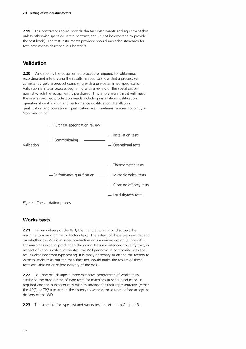
2.20 Validation is the documented procedure required for obtaining,recording and interpreting the results needed to show that a process willconsistently yield a product complying with a pre-determined specification.Validation is a total process beginning with a review of the specificationagainst which the equipment is purchased. This is to ensure that it will meetthe user’s specified production needs including installation qualification,operational qualification and performance qualification. Installationqualification and operational qualification are sometimes referred to jointly as‘commissioning’.
Figure 1 The validation process
Works tests
2.21 Before delivery of the WD, the manufacturer should subject themachine to a programme of factory tests. The extent of these tests will dependon whether the WD is in serial production or is a unique design (a ‘one-off’).For machines in serial production the works tests are intended to verify that, inrespect of various critical attributes, the WD performs in conformity with theresults obtained from type testing. It is rarely necessary to attend the factory towitness works tests but the manufacturer should make the results of thesetests available on or before delivery of the WD.
2.22 For ‘one-off’ designs a more extensive programme of works tests,similar to the programme of type tests for machines in serial production, isrequired and the purchaser may wish to arrange for their representative (eitherthe AP(S) or TP(S)) to attend the factory to witness these tests before acceptingdelivery of the WD.
2.23 The schedule for type test and works tests is set out in Chapter 3.
2.0 Testing of washer-disinfectors
Purchase specification review
Installation testsCommissioning
Validation Operational tests
Thermometric tests
Performance qualification Microbiological tests
Cleaning efficacy tests
Load dryness tests
13
Commissioning
2.24 Commissioning is defined as the process of obtaining anddocumenting evidence that the equipment has been provided and installedwithin the agreed purchase specification, and that it functions within pre-determined limits when operated in accordance with the manufacturer’sinstructions.
2.25 Commissioning consists of a series of installation tests to be carried outby the contractor and operational tests to be carried out by the TP(S).
Installation tests
2.26 The contractor should carry out the required installation checks ondelivery of the WD, to ensure that the WD has been supplied and installedcorrectly, is safe to operate, has been provided with satisfactory services thatdo not impair the performance of the WD, and that in operation the WD doesnot interfere with other equipment.
2.27 Ancillary equipment such as service supplies and ventilation systemsshould checked by the contractor responsible for their installation.
2.28 When these checks have been completed and found satisfactory thecontractor should carry out the installation tests necessary to demonstrate thatthe WD is working satisfactorily. The contractor is not required to carry outany thermometric tests unless these were specified in the purchase contract.Any assistance required from the purchaser should be agreed as part of thepurchase contract.
2.29 If any modification, maintenance or repair work is carried out on thesteam, water, compressed air ventilation or drainage systems after theinstallation tests have been completed, the relevant installation tests should berepeated before the operational tests are undertaken.
2.30 The schedule for installation checks and tests is set out in Chapter 4.
Operational tests
2.31 When the WD has been installed and accepted the TP(S) should carryout a sequence of operational performance tests to evaluate the basicperformance and safety of the WD. Some of these tests are identical to thosespecified as installation tests and need not be repeated if operational testingfollows within ten working days of the completion of the installation tests.
2.32 The schedule for operational tests is set out in Chapter 5.
Performance qualification
2.33 Performance qualification is defined as the process of obtainingdocumented evidence that the equipment, as commissioned, will produce anacceptable product when operated in accordance with the specification.
2.0 Testing of washer-disinfectors
2.34 Performance qualification consists of tests designed to show that:
a. soil removal and cleaning have been effective throughout the load andthe WD chamber, and the products are of the required standard ofcleanliness, free from process residues (when applicable);
b. disinfection conditions have been attained throughout the load and theWD chamber, and to the required standard for the type of load beingprocessed. A thermometric test is sufficient for WDs employing athermal disinfection process. Additional microbiological tests will berequired for WDs that use chemical disinfectants and may be necessaryfor WDs where the nature of the load or loading conditions do notpermit thermometric monitoring which accurately reflects theconditions pertaining in the load.
2.35 In principle, it might be argued that a performance qualification test isrequired for each loading condition that a WD is required to process. Inpractice, it is possible to identify reference loads and reference loadingconditions which present an equal or greater challenge to the process than theloads which may be encountered in normal use.
Documentation
2.36 Accurate and efficient record keeping is an essential part of themanagement of a WD. The extent and nature of the records that are necessaryvaries with the type of WD and the use to which it is put. Guidance is given inHTM 2030 ‘Operational management’.
Summary sheets
2.37 On completion of the validation process, and before leaving thepremises, the TP(S) should prepare a summary report containing the results ofthe commissioning and performance qualification tests and essential workingdata.
2.38 The summary report should be signed by the TP(S) and countersignedby the user to certify that the WD is fit for use.
2.39 Summary reports should be securely retained by the user and beavailable for ready reference.
Validation report
2.40 Within one month of the completion of the validation process the TP(S)should prepare a full validation report which should include:
a. all the data supplied by the contractor, collected during the installationchecks and tests with written confirmation that they meet themanufacturer’s specification;
b. written confirmation that the calibration of all measuring instrumentsfitted to the WD have been verified;
c. all the data collected during the commissioning tests, with writtenconfirmation that they meet the specified requirements;
d. data showing the correlation between the performance of themeasuring instruments fitted to the WD and the test instruments usedduring commissioning and performance qualification;
14
2.0 Testing of washer-disinfectors
e. reports containing all the data collected during the performancequalification tests with written confirmation from the TP(S) and the userof the loading conditions and types of load (including when necessaryreference to specific individual items) which may be satisfactorilyprocessed in the WD.
2.41 When data is in the form of electronic data files, the report shouldinclude copies of disks or tapes containing the data in a format agreed withthe user and a print out of the directory of each, annotated to show wherethe data for each test is to be found.
2.42 The TP(S) should certify that all necessary tests have been carried outand that the results were satisfactory.
2.43 The records of any microbiological tests should be signed by themicrobiologist.
2.44 The AP(S) should review and countersign the completed validationreport.
2.45 The validation report should be retained by the User. Copies may beretained as necessary by the TP(S), the AP(S), the microbiologist and, whereapplicable, the quality controller.
Periodic tests
2.46 After validation and when the WD is passed into service, it should besubject to a schedule of periodic tests at daily, weekly, quarterly and yearlyintervals.
2.47 The user and the TP(S) are responsible for the periodic tests.
2.48 The daily, weekly and quarterly test schedules provide evidence thatthe WD continues to operate within the limits established duringcommissioning.
2.49 The yearly test schedule is a revalidation procedure and provides amore comprehensive test programme than the other periodic tests; it serves todemonstrate that data collected during commissioning and the performancequalification remain valid.
Revalidation
2.50 In addition to annual revalidation, revalidation is required under thefollowing circumstances:
a. when the WD is to be returned to service after repair or componentreplacement of part of the systems which affect satisfactory attainmentof the pre-set variables of the operating cycle;
b. when the pre-set values of the cycle variables have been modified;
c. when the software in a programmable electronic system (PES), used forcontrol of the process, has been modified;
d. whenever the user or AP(S) advises that revalidation is necessary;
15
2.0 Testing of washer-disinfectors
16
2.0 Testing of washer-disinfectors
e. whenever it is required by an authorised inspectorate or licensingauthority.
2.51 The full revalidation procedure is identical to that specified for theyearly test. See Chapter 7.
2.52 It will not always be necessary to carry out a full revalidation and theadvice of the AP(S) should be sought on which tests are required following anyparticular event.
Repeat validation
2.53 Revalidation and periodic tests are designed to establish the continuedconformance of the equipment and its performance with data establishedduring the original validation study.
2.54 There are occasions when it may be necessary to repeat the full set oftests carried out during the initial validation in order to obtain a new set ofdata.
2.55 Repeat validation will be necessary:
a. when the WD is modified to such an extent that it must be presumedthat the original data is no longer valid;
b. when a WD, other than a table top machine, has been moved andinstalled at a new site;
c. when the WD has been dismantled or extensively overhauled;
d. whenever the user or AP(S) advises that repeat validation is necessary;
e. whenever it is required by an authorised inspectorate or licensingauthority;
f. whenever revalidation fails to confirm compliance with the originaldata and no cause for the discrepancy can be found.
It will not always be necessary to carry out a full repeat validation and theadvice of the AP(S) should be sought as to which tests are required followingany particular event.
Types of test
2.56 The tests listed in the schedules fall into the following categories.
a. Automatic control tests which are designed to verify the correctfunctioning of the operating cycle from the readings obtained from theinstruments fitted to the WD.
b. Thermometric tests which are designed to provide assurance that thetemperature requirements for disinfection are met by using accuratemeasuring equipment, independent of the instruments fitted to theWD to monitor the temperatures attained within the chamber andreference loads.
c. Microbiological tests which are designed to show that disinfection(sterilization) conditions are attained when thermometric methodsalone are inadequate for this purpose.
d. Cleaning efficacy tests which are designed to show, by monitoringthe removal of a test soil, that the process will effectively cleanproducts of the type to be processed.
2.57 Other performance tests specific to certain types of WD are designedto provide assurance that the WD will perform correctly under the anticipatedconditions of use.
Procedure on failure of a test
2.58 There should be no difficulty in ensuring that a correctly installed andmaintained WD will comply with both the validation tests and periodic testsdescribed.
2.59 Failure of a test generally indicates that a WD is not working tospecification and it should be withdrawn from service and the failureinvestigated.
2.60 In practice the action to be taken is a matter of judgement and willdepend on the nature of the failure and the use to which the WD is beingput. It may be acceptable for the WD to continue operating under carefullydefined restrictions until the cause of the failure can be established andrectified.
2.61 The AP(S) and the user should agree the course of action to be taken.
2.62 The user has the ultimate responsibility for certifying that the WD is fitfor use.
Inter-relationship of test programmes
2.63 The tests described in this volume of HTM 2030 are intended for use intype tests, works tests, commissioning (installation and operational tests), andperformance qualification (thermometric tests, microbiological tests, cleaningefficacy tests and load dryness tests), and routine periodic tests.
2.64 The inter-relationship of the various test programmes, the place wherethey would usually be conducted and the responsibility for conducting thetests are shown in Figure 2.
2.65 The circumstances under which each of the test schedules should beapplied is given in Table 1 ‘Summary of test programmes for washer-disinfectors’.
2.66 The programmes of tests should be applied to all WDs where relevant.Details are given under the test schedules for particular types of WD.
17
2.0 Testing of washer-disinfectors
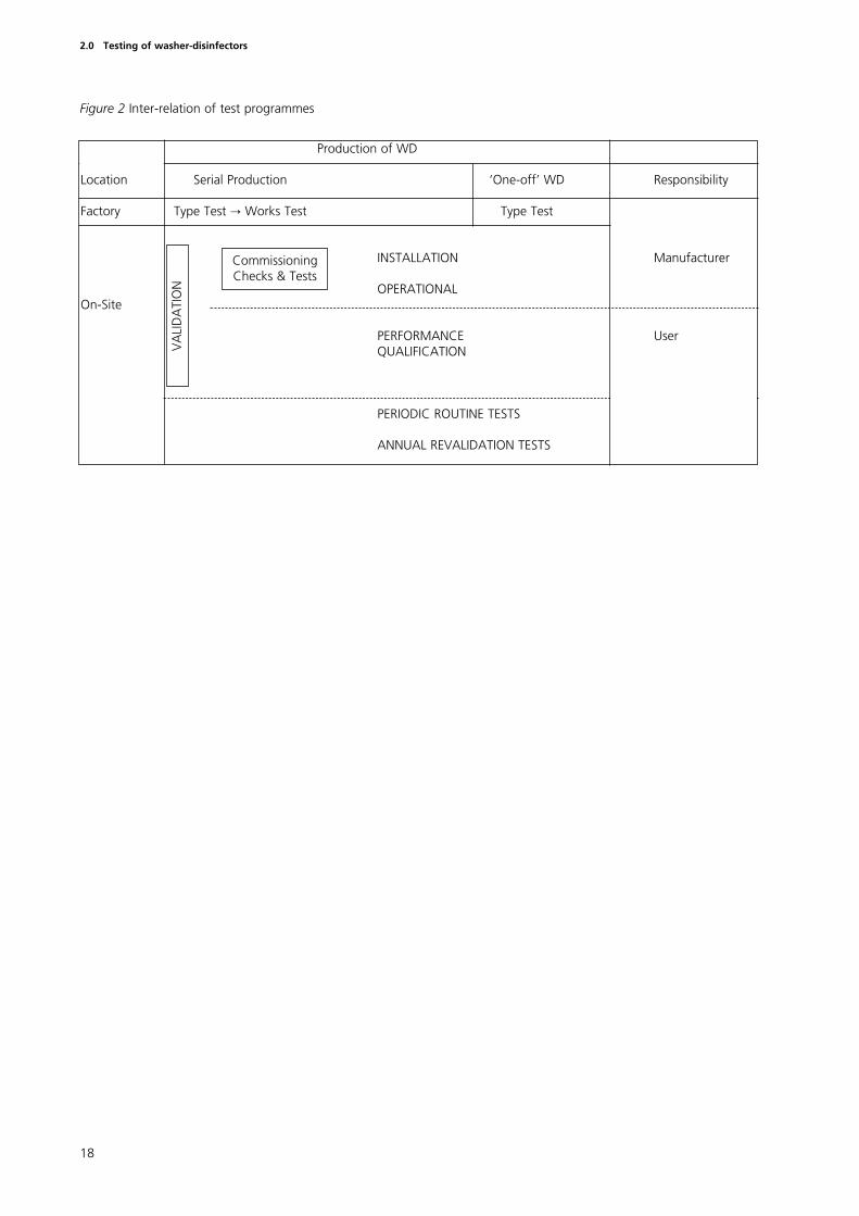
Figure 2 Inter-relation of test programmes
18
2.0 Testing of washer-disinfectors
Production of WD
Location Serial Production ‘One-off’ WD Responsibility
Factory Type Test Õ Works Test Type Test
INSTALLATION Manufacturer
OPERATIONALOn-Site
PERFORMANCE User QUALIFICATION
PERIODIC ROUTINE TESTS
ANNUAL REVALIDATION TESTS
Commissioning Checks & Tests
VA
LID
ATI
ON
Introduction
3.1 The manufacturer carries out type tests on representative samples ofWDs in serial production to demonstrate compliance of the WD design withits specification and/or published Standards as appropriate.
3.2 The manufacturer carries out works tests on each WD before it leavesthe manufacturing site to ensure that each WD meets specification.
3.3 For WDs in serial production the programme of tests required for theworks test is usually a reduced set of the tests in the schedule for type testing.
3.4 For WDs of ‘one-off’ design the schedule of works tests wouldnecessarily be the same as the schedule for type testing.
3.5 Type tests, and more rarely works tests on one-off designs, may becarried out or witnessed by a third party to allow certification of the productto a relevant standard eg BS 2745 Part 2 or Part 3. The product certificationscheme run by BSI leads to the award of the ‘kitemark’ for certified products.A similar scheme is operated through CEN for products complying withEuropean Standards and compliant products may carry the CEN ‘keymark’.Those clinical WDs which are classified as medical devices and are supplied on,or after, the 14 June 1998 will be required to bear the CEN marking.
3.6 The manufacturer should make available to the purchaser the resultsof type tests and works tests on or before delivery of the WD.
3.7 It will rarely be necessary for the purchaser, or their representative, tovisit the manufacturer’s works to witness works testing except, perhaps, in thecase of ‘one-off’ machines. The advice of the AP(S) should be sought.
3.8 A summary of the tests which should be included in a programme oftype tests and works tests is shown in Table 1.
19
3.0 Schedule of type tests and works tests
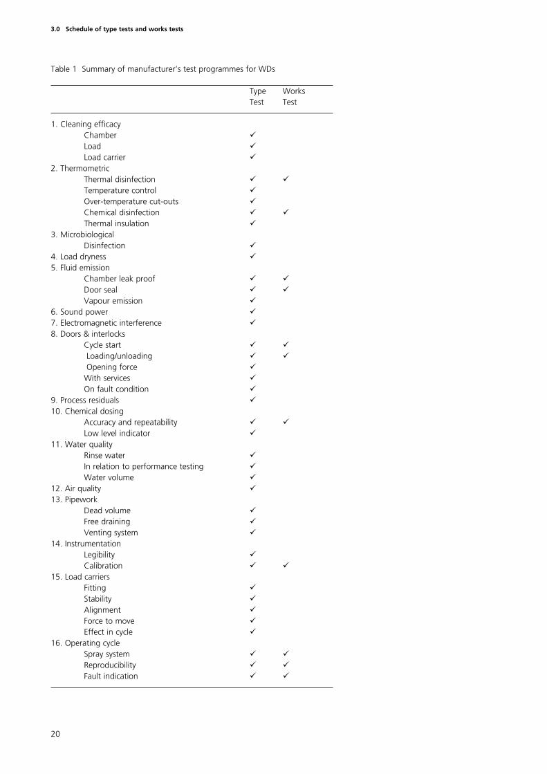
Table 1 Summary of manufacturer’s test programmes for WDs
Type WorksTest Test
1. Cleaning efficacyChamber üLoad üLoad carrier ü
2. Thermometric Thermal disinfection ü üTemperature control üOver-temperature cut-outs üChemical disinfection ü üThermal insulation ü
3. MicrobiologicalDisinfection ü
4. Load dryness ü5. Fluid emission
Chamber leak proof ü üDoor seal ü üVapour emission ü
6. Sound power ü7. Electromagnetic interference ü8. Doors & interlocks
Cycle start ü üLoading/unloading ü üOpening force ü
With services üOn fault condition ü
9. Process residuals ü10. Chemical dosing
Accuracy and repeatability ü üLow level indicator ü
11. Water quality Rinse water üIn relation to performance testing üWater volume ü
12. Air quality ü13. Pipework
Dead volume üFree draining üVenting system ü
14. Instrumentation Legibility üCalibration ü ü
15. Load carriers Fitting üStability üAlignment üForce to move üEffect in cycle ü
16. Operating cycle Spray system ü üReproducibility ü üFault indication ü ü
20
3.0 Schedule of type tests and works tests
Introduction
4.1 On delivery of the WD the contractor should carry out the installationchecks included in the contract and as set out in this chapter to establish that:
a. the WD has been provided and installed correctly;
b. the WD is safe to operate;
c. the WD does not interfere with other equipment;
d. all connected services are satisfactory and do not prevent attainment ofthe designed cleaning and disinfection performance of the WD.
4.2 The contractor responsible for installing the WD should carry outinstallation checks on services and other ancillary equipment. These checksshould be completed and all services and ancillary equipment found to besatisfactory before carrying out installation checks on the WD itself.
4.3 The contractor responsible for installing the WD should carry out anyadditional checks specified by the manufacturer.
4.4 The TP(S) should be carry out any checks specified in this chapterwhich were not included in the purchase contract for the WD.
4.5 As a safety precaution, checks on chemical dosing systems (forchemical additives such as detergents, disinfectants etc) should be carried outusing water. Checks on fume extract systems designed to eliminate personnelexposure to hazardous chemicals (for example glutaraldehyde) should becarried out using a non-hazardous substitute or a smoke test.
Checks on ancillary equipment
4.6 Ancillary equipment should, whenever practicable, be installed andcommissioned before validation of the WD begins.
4.7 When the checks on ancillary equipment require the WD to be inoperation, the TP(S) should carry them out in cooperation with the contractorfor the WD.
4.8 The contractor for the WD is not responsible for the correctfunctioning of services and ancillary equipment unless this was agreed in thepurchase contract.
21
4.0 Schedule of installation tests
Engineering services
4.9 Check that the following requirements are met.
a. The engineering services have been installed correctly, they areadequate to meet the demands of the WD, they do not leak and allnecessary isolating valves/switches and test points have beeninstalled.
b. Drains remove effluent effectively when all plant in the vicinity,including the WD, is connected and operating.
c. The water treatment plant (if fitted) operates correctly and thequality of water supplied for each stage of the process is inaccordance with the specification.
d. The provision for storage, handling and connection to the WD for allprocess chemicals, meets the requirements for safe handling ofpotentially hazardous chemicals.
e. The exhaust ventilation and/or condenser unit fitted to the WD isadequate to remove the hot, humid air evolved from the washing,thermal disinfection and drying and unloading processes.
f. For WDs employing volatile process chemicals, the exhaustventilation maintains the environmental concentration below anylimit specified for occupational exposure and that the discharge is toa safe place.
Additional checks for WDs using a chemical disinfectant
4.10 WDs using chemical disinfectants require further tests to the ventilationand safety systems because of the possible emission of toxic gases or vapours.
4.11 For WDs using a chemical disinfectant check that the ventilation systemwithin the loading (or unloading) area of the WD, the plant room (ifapplicable) and the storage area for the disinfectant meet the specifiedrequirements. Particular attention should be paid to the following:
a. the installation meets the manufacturer’s specifications;
b. air flow is from the operator towards the WD and air does not flowfrom the plant room (if applicable) or disinfectant storage area into theloading (or unloading) area;
c. exhaust systems are non-recirculating and their discharges comply withrelevant safety Regulations.
4.12 Check that local exhaust ventilation incorporated in the WD or installedas a dedicated accessory meets the specified requirements. Particular attentionshould be paid to the following:
a. air flow is from the operator towards the WD;
b. the rate of flow complies with the specified requirements;
c. the exhaust discharge complies with safety Regulations.
4.13 When the disinfectant solution is intended to be discharged to drainensure that the drainage system is trapped, sealed and vented to a safeposition. The drainage system should be checked to ensure that it is notpossible for toxic materials to be vented into any other part of the building.
The maximum permittedconcentration and the method ofdetection and analysis will depend onthe chemical being used.
22
4.0 Schedule of installation tests
Checks on the WD
Preliminary checks
4.14 Check that the electrical equipment on the WD is correctly connectedto the electrical service. Carry out the following electrical tests:
a. insulation resistance
b. phase sequence (for 3 phase installations)
c. polarity
d. bonding and earth continuity
e. emergency stop
4.15 After the WD has been installed, check that the followingrequirements are met:
a. the manufacturer has supplied all the documents specified in thecontract;
b. the WD has been supplied and installed in accordance with thecontract;
c. calibration verification certificates for the measuring instruments andcontroller(s) on the WD have been supplied;
d. no defects are apparent from a visual inspection of the WD;
e. all supports, bases and fixings are secure and without imposed strainfrom service connections;
f. thermal insulation is in good condition and securely attached;
g. security and settings of door safety switches are in compliance withdata supplied by the manufacturer;
h. keys, codes or tools required to operate locked controls and controlover-rides have been supplied, operate correctly and only operate thecontrol for which it is intended;
j. loading conveyors and trolleys, load carriers and load baskets areeffective and safe in use.
Functional checks
4.16 During an operating cycle, with an empty chamber, check that thefollowing requirements are met (several cycles may be necessary to completeall the checks).
a. The selection of automatic or manual control is by key code or tool.The selection of one control mode inactivates the other control mode.
b. Under automatic control, water, steam, compressed air or chemicaladditives cannot be admitted into the chamber, and the operating cyclecannot start until the door is closed.
c. Under manual control the operator can advance the cycle onlysequentially through each stage. Any stages designed to removechemical additives from the chamber and load cannot be circumvented.
d. Throughout the cycle the indicated and recorded values of cyclevariables are within the limits specified by the manufacturer.
23
4.0 Schedule of installation tests
e. Throughout the cycle there are no leaks of water, steam aerosols, toxicchemicals or effluent.
f. There is no evidence of interference to or from other equipmentconnected to the same services.
g. There is no evidence of electromagnetic interference to or from otherequipment.
h. Operation and reading of all instruments appear to be satisfactory.
j. The temperature of surfaces routinely handled by the operator doesnot exceed those specified in HTM 2030 ‘Design considerations’.
k. The effluent temperature does not exceed that specified in HTM 2030‘Design considerations’.
4.17 At the end of the cycle check that the following requirements are met.
a. The door opening system cannot be opened until the cycle has beencompleted, that is, the automatic controller has operated in accordancewith its specification.
b. For systems incorporating one or more cycle stages at pressures 200 mbar above or below atmospheric pressure,
(i) the door opening system cannot be operated until the chamberhas been vented to atmosphere and the chamber pressure is within200 mbar of atmospheric pressure;
(ii) the door retaining parts cannot be released until the seal betweenthe door and chamber has been broken, and the chamber iseffectively vented to atmospheric pressure.
Response to external faults
4.18 It is necessary to check that the WD reacts correctly and safely whenexposed to a number of external fault conditions; that is, a safety hazard is notcreated and a false indication of satisfactory completion of a cycle is notobtained.
4.19 During each stage of an operating cycle, check the response of the WDto the following simulated faults (as appropriate to the type of WD):
a. operation of the emergency stop button;
b. power failure;
c. water pressure too low;
d. water pressure too high;
e. steam pressure too low;
f. steam pressure too high;
g. compressed air pressure too low;
h. compressed air pressure too high;
j. failure of chemical additive supply (detergent, rinse aid, disinfectantetc);
k. failure of extract ventilation.
24
4.0 Schedule of installation tests
Introduction
5.1 To demonstrate compliance with specifications the contractor shouldcarry out installation checks and tests before operational tests are carried (seeChapter 4); these may be repeated by the TP(S) if required.
5.2 Operational tests and performance qualification (see Chapter 6) testsare carried out by the TP(S).
5.3 The schedules for the tests are set out for each type of WD in Tables 2a to 2g inclusive.
5.4 Each test is cross-referenced to a detailed description of the testprocedure in Chapter 9. Unless otherwise specified in Chapter 9 the testsshould be carried out with the WD at normal working temperature, whichmay require a ‘warm-up’ run to be carried out before commencement oftesting.
5.5 A number of the tests required can be carried out concurrently on thesame operating cycle and this is also indicated in Chapter 9.
5.6 The calibration of test equipment should be checked before and afteruse as described in Chapter 9.
5.7 In principle, performance qualification tests should be carried out afteroperational tests have been completed. However, for WDs employing athermal disinfection stage the performance qualification tests may beperformed while the temperature sensors used in the commissioning tests arestill in place.
25
5.0 Schedule of operational tests
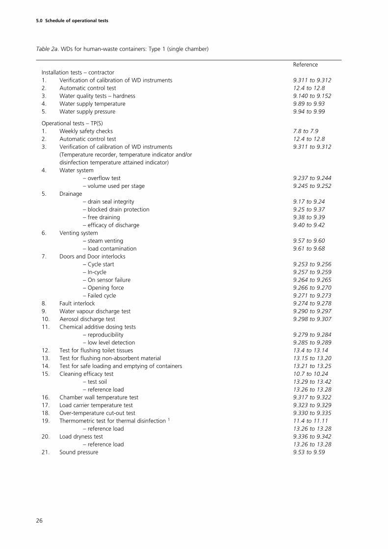
Table 2a. WDs for human-waste containers: Type 1 (single chamber)
ReferenceInstallation tests – contractor1. Verification of calibration of WD instruments 9.311 to 9.3122. Automatic control test 12.4 to 12.83. Water quality tests – hardness 9.140 to 9.1524. Water supply temperature 9.89 to 9.935. Water supply pressure 9.94 to 9.99
Operational tests – TP(S)1. Weekly safety checks 7.8 to 7.92. Automatic control test 12.4 to 12.83. Verification of calibration of WD instruments 9.311 to 9.312
(Temperature recorder, temperature indicator and/or disinfection temperature attained indicator)
4. Water system– overflow test 9.237 to 9.244– volume used per stage 9.245 to 9.252
5. Drainage– drain seal integrity 9.17 to 9.24– blocked drain protection 9.25 to 9.37– free draining 9.38 to 9.39– efficacy of discharge 9.40 to 9.42
6. Venting system– steam venting 9.57 to 9.60– load contamination 9.61 to 9.68
7. Doors and Door interlocks– Cycle start 9.253 to 9.256– In-cycle 9.257 to 9.259– On sensor failure 9.264 to 9.265– Opening force 9.266 to 9.270– Failed cycle 9.271 to 9.273
8. Fault interlock 9.274 to 9.2789. Water vapour discharge test 9.290 to 9.29710. Aerosol discharge test 9.298 to 9.30711. Chemical additive dosing tests
– reproducibility 9.279 to 9.284– low level detection 9.285 to 9.289
12. Test for flushing toilet tissues 13.4 to 13.1413. Test for flushing non-absorbent material 13.15 to 13.2014. Test for safe loading and emptying of containers 13.21 to 13.2515. Cleaning efficacy test 10.7 to 10.24
– test soil 13.29 to 13.42– reference load 13.26 to 13.28
16. Chamber wall temperature test 9.317 to 9.32217. Load carrier temperature test 9.323 to 9.32918. Over-temperature cut-out test 9.330 to 9.33519. Thermometric test for thermal disinfection 1 11.4 to 11.11
– reference load 13.26 to 13.2820. Load dryness test 9.336 to 9.342
– reference load 13.26 to 13.2821. Sound pressure 9.53 to 9.59
26
5.0 Schedule of operational tests
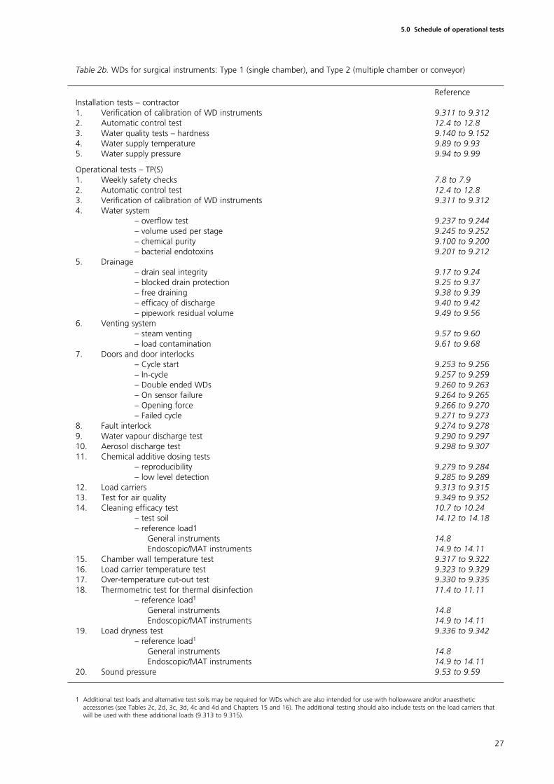
Table 2b. WDs for surgical instruments: Type 1 (single chamber), and Type 2 (multiple chamber or conveyor)
ReferenceInstallation tests – contractor1. Verification of calibration of WD instruments 9.311 to 9.3122. Automatic control test 12.4 to 12.83. Water quality tests – hardness 9.140 to 9.1524. Water supply temperature 9.89 to 9.935. Water supply pressure 9.94 to 9.99
Operational tests – TP(S)1. Weekly safety checks 7.8 to 7.92. Automatic control test 12.4 to 12.83. Verification of calibration of WD instruments 9.311 to 9.3124. Water system
– overflow test 9.237 to 9.244– volume used per stage 9.245 to 9.252– chemical purity 9.100 to 9.200– bacterial endotoxins 9.201 to 9.212
5. Drainage– drain seal integrity 9.17 to 9.24– blocked drain protection 9.25 to 9.37– free draining 9.38 to 9.39– efficacy of discharge 9.40 to 9.42– pipework residual volume 9.49 to 9.56
6. Venting system– steam venting 9.57 to 9.60– load contamination 9.61 to 9.68
7. Doors and door interlocks– Cycle start 9.253 to 9.256– In-cycle 9.257 to 9.259– Double ended WDs 9.260 to 9.263– On sensor failure 9.264 to 9.265– Opening force 9.266 to 9.270– Failed cycle 9.271 to 9.273
8. Fault interlock 9.274 to 9.2789. Water vapour discharge test 9.290 to 9.29710. Aerosol discharge test 9.298 to 9.30711. Chemical additive dosing tests
– reproducibility 9.279 to 9.284– low level detection 9.285 to 9.289
12. Load carriers 9.313 to 9.31513. Test for air quality 9.349 to 9.35214. Cleaning efficacy test 10.7 to 10.24
– test soil 14.12 to 14.18– reference load1
General instruments 14.8 Endoscopic/MAT instruments 14.9 to 14.11
15. Chamber wall temperature test 9.317 to 9.32216. Load carrier temperature test 9.323 to 9.32917. Over-temperature cut-out test 9.330 to 9.33518. Thermometric test for thermal disinfection 11.4 to 11.11
– reference load1
General instruments 14.8 Endoscopic/MAT instruments 14.9 to 14.11
19. Load dryness test 9.336 to 9.342– reference load1
General instruments 14.8 Endoscopic/MAT instruments 14.9 to 14.11
20. Sound pressure 9.53 to 9.59
1 Additional test loads and alternative test soils may be required for WDs which are also intended for use with hollowware and/or anaestheticaccessories (see Tables 2c, 2d, 3c, 3d, 4c and 4d and Chapters 15 and 16). The additional testing should also include tests on the load carriers thatwill be used with these additional loads (9.313 to 9.315).
27
5.0 Schedule of operational tests
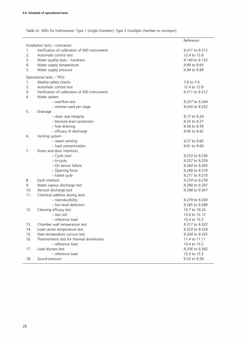
Table 2c. WDs for hollowware: Type 1 (single chamber), Type 2 (multiple chamber or conveyor)
ReferenceInstallation tests – contractor1. Verification of calibration of WD instruments 9.311 to 9.3122. Automatic control test 12.4 to 12.83. Water quality tests – hardness 9.140 to 9.1524. Water supply temperature 9.89 to 9.935. Water supply pressure 9.94 to 9.99
Operational tests – TP(S)1. Weekly safety checks 7.8 to 7.92. Automatic control test 12.4 to 12.83. Verification of calibration of WD instruments 9.311 to 9.3124. Water system
– overflow test 9.237 to 9.244– volume used per stage 9.245 to 9.252
5. Drainage– drain seal integrity 9.17 to 9.24– blocked drain protection 9.25 to 9.37– free draining 9.38 to 9.39– efficacy of discharge 9.40 to 9.42
6. Venting system– steam venting 9.57 to 9.60– load contamination 9.61 to 9.68
7. Doors and door interlocks– Cycle start 9.253 to 9.256– In-cycle 9.257 to 9.259– On sensor failure 9.264 to 9.265– Opening force 9.266 to 9.270– Failed cycle 9.271 to 9.273
8. Fault interlock 9.274 to 9.2789. Water vapour discharge test 9.290 to 9.29710. Aerosol discharge test 9.298 to 9.30711. Chemical additive dosing tests
– reproducibility 9.279 to 9.284– low level detection 9.285 to 9.289
12. Cleaning efficacy test 10.7 to 10.24– test soil 15.6 to 15.12– reference load 15.4 to 15.5
13. Chamber wall temperature test 9.317 to 9.32214. Load carrier temperature test 9.323 to 9.32915. Over-temperature cut-out test 9.330 to 9.33516. Thermometric test for thermal disinfection 11.4 to 11.11
– reference load 15.4 to 15.517. Load dryness test 9.336 to 9.342
– reference load 15.4 to 15.518. Sound pressure 9.53 to 9.59
28
5.0 Schedule of operational tests
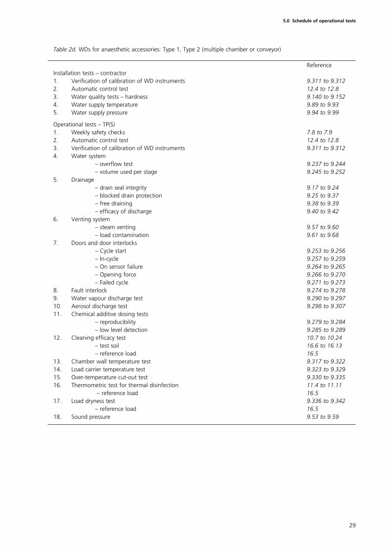
Table 2d. WDs for anaesthetic accessories: Type 1, Type 2 (multiple chamber or conveyor)
ReferenceInstallation tests – contractor1. Verification of calibration of WD instruments 9.311 to 9.3122. Automatic control test 12.4 to 12.83. Water quality tests – hardness 9.140 to 9.1524. Water supply temperature 9.89 to 9.935. Water supply pressure 9.94 to 9.99
Operational tests – TP(S)1. Weekly safety checks 7.8 to 7.92. Automatic control test 12.4 to 12.83. Verification of calibration of WD instruments 9.311 to 9.3124. Water system
– overflow test 9.237 to 9.244– volume used per stage 9.245 to 9.252
5. Drainage– drain seal integrity 9.17 to 9.24– blocked drain protection 9.25 to 9.37– free draining 9.38 to 9.39– efficacy of discharge 9.40 to 9.42
6. Venting system– steam venting 9.57 to 9.60– load contamination 9.61 to 9.68
7. Doors and door interlocks– Cycle start 9.253 to 9.256– In-cycle 9.257 to 9.259– On sensor failure 9.264 to 9.265– Opening force 9.266 to 9.270– Failed cycle 9.271 to 9.273
8. Fault interlock 9.274 to 9.2789. Water vapour discharge test 9.290 to 9.29710. Aerosol discharge test 9.298 to 9.30711. Chemical additive dosing tests
– reproducibility 9.279 to 9.284– low level detection 9.285 to 9.289
12. Cleaning efficacy test 10.7 to 10.24– test soil 16.6 to 16.13– reference load 16.5
13. Chamber wall temperature test 9.317 to 9.32214. Load carrier temperature test 9.323 to 9.32915. Over-temperature cut-out test 9.330 to 9.33516. Thermometric test for thermal disinfection 11.4 to 11.11
– reference load 16.517. Load dryness test 9.336 to 9.342
– reference load 16.518. Sound pressure 9.53 to 9.59
29
5.0 Schedule of operational tests
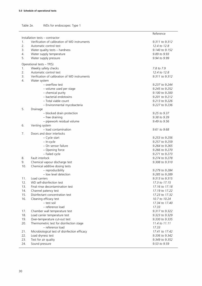
Table 2e. WDs for endoscopes: Type 1
ReferenceInstallation tests – contractor1. Verification of calibration of WD instruments 9.311 to 9.3122. Automatic control test 12.4 to 12.83. Water quality tests – hardness 9.140 to 9.1524. Water supply temperature 9.89 to 9.935. Water supply pressure 9.94 to 9.99
Operational tests – TP(S)1. Weekly safety checks 7.8 to 7.92. Automatic control test 12.4 to 12.83. Verification of calibration of WD instruments 9.311 to 9.3124. Water system
– overflow test 9.237 to 9.244– volume used per stage 9.245 to 9.252– chemical purity 9.100 to 9.200– bacterial endotoxins 9.201 to 9.212– Total viable count 9.213 to 9.226– Environmental mycobacteria 9.227 to 9.236
5. Drainage– blocked drain protection 9.25 to 9.37– free draining 9.38 to 9.39– pipework residual volume 9.49 to 9.56
6. Venting system– load contamination 9.61 to 9.68
7. Doors and door interlocks– Cycle start 9.253 to 9.256– In-cycle 9.257 to 9.259– On sensor failure 9.264 to 9.265– Opening force 9.266 to 9.270– Failed cycle 9.271 to 9.273
8. Fault interlock 9.274 to 9.2789. Chemical vapour discharge test 9.308 to 9.31010. Chemical additive dosing tests
– reproducibility 9.279 to 9.284– low level detection 9.285 to 9.289
11. Load carriers 9.313 to 9.31512. WD self-disinfection test 17.3 to 17.1513. Final rinse decontamination test 17.16 to 17.1814. Channel patency test 17.19 to 17.2215. Disinfectant concentration test 17.23 to 17.3216. Cleaning efficacy test 10.7 to 10.24
– test soil 17.34 to 17.40– reference load 17.33
17. Chamber wall temperature test 9.317 to 9.32218. Load carrier temperature test 9.323 to 9.32919. Over-temperature cut-out test 9.330 to 9.33520. Thermometric test for disinfection stage 11.4 to 11.11
– reference load 17.33 21. Microbiological test of disinfection efficacy 17.41 to 17.4222. Load dryness test 9.336 to 9.34223. Test for air quality 9.349 to 9.35224. Sound pressure 9.53 to 9.59
30
5.0 Schedule of operational tests
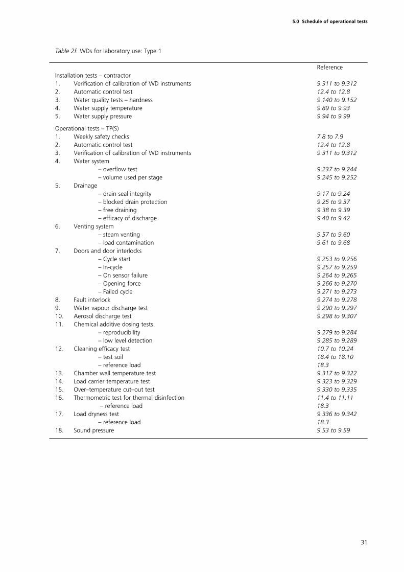
Table 2f. WDs for laboratory use: Type 1
ReferenceInstallation tests – contractor1. Verification of calibration of WD instruments 9.311 to 9.3122. Automatic control test 12.4 to 12.83. Water quality tests – hardness 9.140 to 9.1524. Water supply temperature 9.89 to 9.935. Water supply pressure 9.94 to 9.99
Operational tests – TP(S)1. Weekly safety checks 7.8 to 7.92. Automatic control test 12.4 to 12.83. Verification of calibration of WD instruments 9.311 to 9.3124. Water system
– overflow test 9.237 to 9.244– volume used per stage 9.245 to 9.252
5. Drainage– drain seal integrity 9.17 to 9.24– blocked drain protection 9.25 to 9.37– free draining 9.38 to 9.39– efficacy of discharge 9.40 to 9.42
6. Venting system– steam venting 9.57 to 9.60– load contamination 9.61 to 9.68
7. Doors and door interlocks– Cycle start 9.253 to 9.256– In-cycle 9.257 to 9.259– On sensor failure 9.264 to 9.265– Opening force 9.266 to 9.270– Failed cycle 9.271 to 9.273
8. Fault interlock 9.274 to 9.2789. Water vapour discharge test 9.290 to 9.29710. Aerosol discharge test 9.298 to 9.30711. Chemical additive dosing tests
– reproducibility 9.279 to 9.284– low level detection 9.285 to 9.289
12. Cleaning efficacy test 10.7 to 10.24– test soil 18.4 to 18.10– reference load 18.3
13. Chamber wall temperature test 9.317 to 9.32214. Load carrier temperature test 9.323 to 9.32915. Over–temperature cut–out test 9.330 to 9.33516. Thermometric test for thermal disinfection 11.4 to 11.11
– reference load 18.317. Load dryness test 9.336 to 9.342
– reference load 18.318. Sound pressure 9.53 to 9.59
31
5.0 Schedule of operational tests
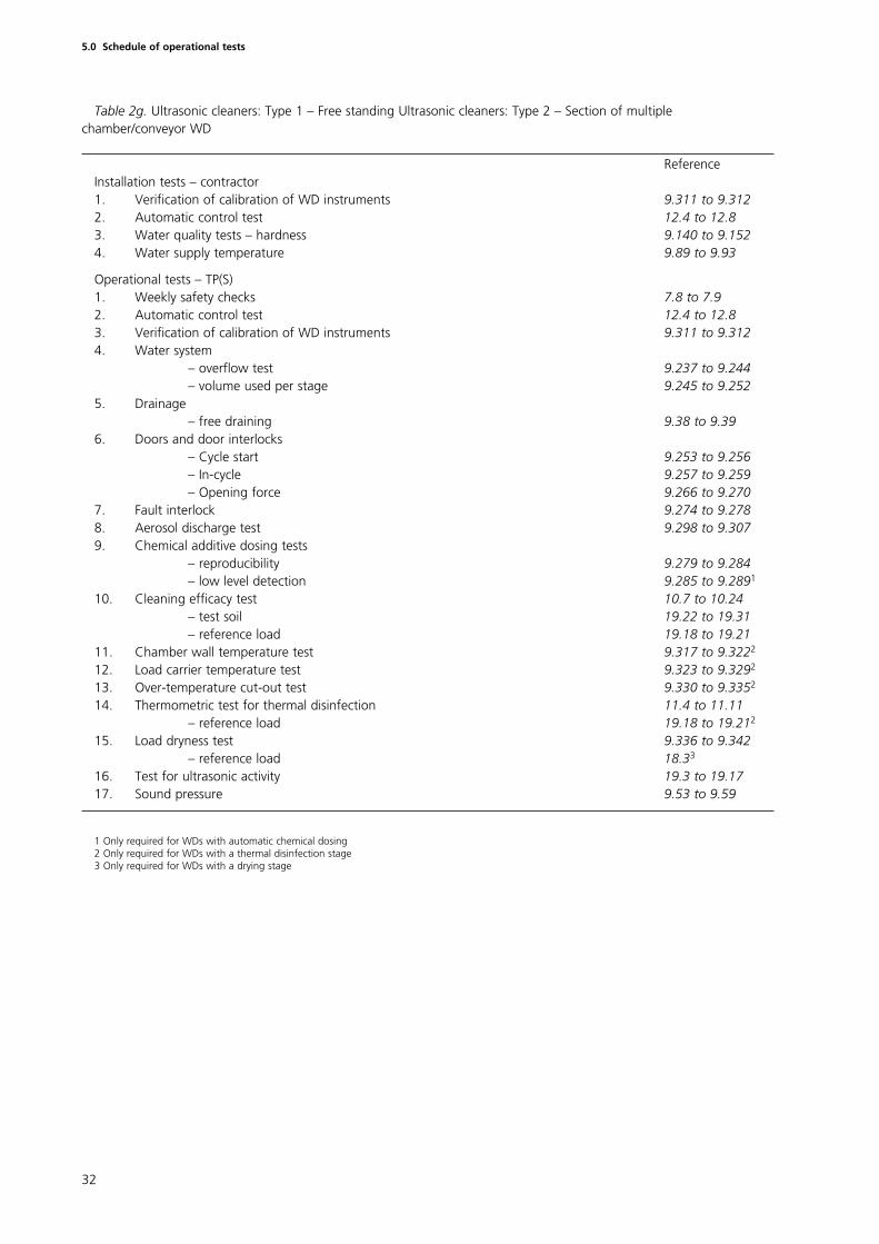
Table 2g. Ultrasonic cleaners: Type 1 – Free standing Ultrasonic cleaners: Type 2 – Section of multiplechamber/conveyor WD
ReferenceInstallation tests – contractor1. Verification of calibration of WD instruments 9.311 to 9.3122. Automatic control test 12.4 to 12.83. Water quality tests – hardness 9.140 to 9.1524. Water supply temperature 9.89 to 9.93
Operational tests – TP(S)1. Weekly safety checks 7.8 to 7.92. Automatic control test 12.4 to 12.83. Verification of calibration of WD instruments 9.311 to 9.3124. Water system
– overflow test 9.237 to 9.244– volume used per stage 9.245 to 9.252
5. Drainage– free draining 9.38 to 9.39
6. Doors and door interlocks– Cycle start 9.253 to 9.256– In-cycle 9.257 to 9.259– Opening force 9.266 to 9.270
7. Fault interlock 9.274 to 9.2788. Aerosol discharge test 9.298 to 9.3079. Chemical additive dosing tests
– reproducibility 9.279 to 9.284– low level detection 9.285 to 9.2891
10. Cleaning efficacy test 10.7 to 10.24– test soil 19.22 to 19.31– reference load 19.18 to 19.21
11. Chamber wall temperature test 9.317 to 9.3222
12. Load carrier temperature test 9.323 to 9.3292
13. Over-temperature cut-out test 9.330 to 9.3352
14. Thermometric test for thermal disinfection 11.4 to 11.11– reference load 19.18 to 19.212
15. Load dryness test 9.336 to 9.342– reference load 18.33
16. Test for ultrasonic activity 19.3 to 19.17 17. Sound pressure 9.53 to 9.59
1 Only required for WDs with automatic chemical dosing2 Only required for WDs with a thermal disinfection stage3 Only required for WDs with a drying stage
32
5.0 Schedule of operational tests
Introduction
6.1 Performance qualification (PQ) is the procedure for obtainingdocumented evidence that the WD, as commissioned, will produce cleanedand/or disinfected goods of the standard required when operated inaccordance with the operational instructions.
6.2 PQ tests are performed as part of the initial validation procedure, aspart of any repeat validation procedure and whenever the user, acting on theadvice of the AP(S), judges that new loading or operating conditions require anew PQ test.
6.3 Circumstances that may lead to new PQ tests would include changesto the quality of the water supply, changes to the chemical additives used inthe cleaning and disinfection process, changes to the loading system or therequirement to process a new type of product.
6.4 Performance qualification should not be undertaken on any WD untilthe requirements of the installation and operational tests specified in Chapters4 and 5 have been met.
6.5 Soil removal efficacy tests are required for all WDs as part of theperformance qualification (see Chapter 10).
6.6 Performance qualification tests are carried out by the TP(S).
6.7 The schedules for the tests are set out for each type of WD in Tables 4a to 4g inclusive.
6.8 Each test is cross-referenced to a detailed description of the testprocedure. Unless otherwise specified, the tests should be carried out with theWD at normal working temperature, which may require a ‘warm-up’ run tobe carried out before commencement of the tests.
6.9 Test data obtained from the PQ tests should be recorded in a writtenPQ report which clearly identifies the loading conditions, the operating cycles,the chemical additives and the water quality used at each stage of the cycle.
6.10 The user should employ the PQ report to confirm the suitability of theprocess for loads which are to be processed. It should be used by the TP(S)and AP(S) as the basis for comparison with subsequent performancerequalification tests.
6.11 Performance requalification (PRQ) is the process of confirming that theWD continues to meet the performance standards established during PQ andthat the working data established during PQ tests remain valid.
6.12 Performance requalification is carried out annually as part of the yearlytest schedule, as part of any revalidation or repeat validation study, orwhenever the user requests such confirmation.
33
6.0 Schedule of performance qualification tests
6.13 Before undertaking performance requalification tests the TP(S) shouldconfirm, either by testing or by reference to current test records, that the WDmeets the requirements of the installation and operational tests.
Loading conditions
6.14 A loading condition is a specified combination of the nature andnumber of load items, the items of chamber furniture, and their distributionwithin the chamber. For example, a load placed on the topmost level of a fourlevel load carrier constitutes a different loading condition from the same loadplaced on the lowest level.
6.15 In principle, validation is not complete until a PQ test has beenperformed for each loading condition that the WD is expected to process.
6.16 In practice, the loading conditions specified in the tests to be carriedout during commissioning are designed to represent the nature of productionloads and to present a greater challenge to the process than production loads.In these cases further PQ tests will not be required; the data obtained from thecommissioning tests will be sufficient.
6.17 PQ tests are required under the following conditions:
a. when the proposed production loading condition presents a greaterchallenge to the process than that presented by the commissioningtests; for example, WDs for surgical instruments will require PQ tests ifthe mass of metal instruments to be processed exceeds that of thestandard test load or if it is intended to process instruments withnarrow lumens;
b. when the nature of the load is not represented by the commissioningtests; for example, WDs for surgical instruments will require PQ tests ifit is intended to process instruments with narrow lumens such asendoscopes.
6.18 When PQ tests are required it is often possible to select a productionload that is known to be a greater challenge to the process than any of theothers. This reference load can then serve as a ‘worst case’ and allow one PQtest to be valid for a range of less demanding conditions.
Surrogate devices
6.19 Many of the devices that constitute the most difficult loads to processin a WD, which therefore require PQ, are difficult to monitor eitherthermometrically or microbiologically, are in short supply and are extremelyexpensive; examples include fibre-optic endoscopes, videoscopes etc.
6.20 A surrogate device is a test piece designed and constructed toemulate the characteristics of a device to facilitate appropriate monitoring ofthe cleaning and disinfecting processes.
6.21 An example of a surrogate device might be a rigid endoscope emulatedby a similar length of stainless steel tube of appropriate diameter and bore.The surrogate device can be constructed to incorporate the appropriatetemperature sensors and so that it may be separated into sections to facilitatethe evaluation of residual test soil or survivors from a microbial challenge.
34
6.0 Schedule of performance qualification tests
6.22 The surrogate device should have similar geometry and thermal massand, as far as may be practicable, should be constructed of the same materialsand with the same surface finishes as the device it is designed to emulate.
6.23 When an instrument presents particular problems in validation themanufacturer of the instrument should be requested to provide details of themethod by which they recommend that PQ studies should be performed.
Cleaning efficacy tests
Native soiling
6.24 Cleaning efficacy tests are intended to demonstrate the ability of theWD to remove or reduce to acceptable levels, soiling and contaminationwhich occurs during normal use of re-usable items.
6.25 Naturally occurring contamination shows considerable variation both inthe nature and proportion of constituents and also in the extent of soilingwhich may occur during use.
6.26 Test methods based on the detection of naturally occurring soiling aredifficult to standardise and show poor reproducibility due to:
• the variation in the composition of the soiling which may affect theease with which soiling is removed;
• the changes in sensitivity of detection which may occur due to variationin composition of the soiling;
• the variation in the extent of soiling.
6.27 A number of methods exist for estimating (both qualitatively andquantitatively) the residual levels of some important soils or components ofsoils. These include detection of blood (Hydrogen peroxide test, Kastle-Meyertest), protein (ninhydrin test, Biuret test) or bacterial endotoxins (LAL test).
6.28 Common practice in the past has been to rely solely upon visualinspection to detect unacceptable levels of residual soiling. This method haspoor sensitivity, is very subjective and can be greatly influenced by a numberof factors including the intensity and nature of the illumination in theinspection area.
Test soils
6.29 Artificial test soils are designed to simulate the nature of native soilingand to be equally, or more difficult to remove.
6.30 By incorporating appropriate marker substances, they can provideimproved sensitivity of detection.
6.31 Test soils can be used to give a quantified loading level, quantifieddetection and hence a quantified estimate of the soil removal which hasoccurred.
6.32 Test soils avoid any hazard which may be associated with native soiling(for example blood borne viruses) which may be of particular concern with themore extensive handling necessary for test work.
35
6.0 Schedule of performance qualification tests
6.33 Worldwide, many different test soils have been specified for testingWDs but they generally fail to meet the key criteria necessary for a test soil.These criteria include:
• a chemically defined formulation (the traditional soils use substancessuch as flour, wall paper paste, fresh egg yolk, horse blood, etc whichintroduce a significant variability);
• a quantitative method of applying the test soil to the surfaces of alltypes of item to be processed;
• a quantitative method of detection of soiling remaining after thewashing-disinfection process;
• validated with a known relationship to native soiling for ease of removal,relevant residual levels etc;
• safe to handle, easy and economical to use.
Standard test soils
6.34 Current proposals for the European standard for WDs are to specify atest method for the validation of test soils. This would allow acceptance of theuse of any test soil which meets the defined criteria and is validated asequivalent to a particular native soil or soils.
6.35 The test soils described in this HTM are those specified in BS 2745. It isapparent that they do not meet the criteria given above but, nevertheless,when used in conjunction with the test for residual soiling, they should be ableto demonstrate that an acceptable level of soil removal has been obtained.
Process residues
6.36 The nature of process residues and the level of such residues that maybe of concern depend on the chemical additives and quality of water usedduring the process and the intended use of the washed and disinfectedproduct.
6.37 The water used for the process may give rise to a number of chemicalresidues on processed items. The most obvious of these is the presence oflimescale from the use of hard water.
6.38 The water used for the process may give rise also to contaminants ofmicrobial origin. Bacterial endotoxins, primarily derived from the cell wall ofGram negative bacteria, may give rise to adverse (pyrogenic) reactions whenintroduced into the mammalian body. Items intended for surgically invasive useor for the preparation or administration of parenteral fluids should be freefrom, or have suitably low levels of, bacterial endotoxins.
6.39 The chemical additives used during the process (detergents, rinse aidsetc) may not be completely removed by the rinsing process. The residual levelwhich may be tolerated will depend upon the nature of the chemical and theintended use of the product. The supplier of any chemical agent used shouldprovide data on the chemical composition of the chemical agent and thebiocompatibility of the components of the chemical agent. The supplier shouldalso provide details of the method of detection, which may be used todetermine whether processed items are free from residuals at the specifiedlevels.
36
6.0 Schedule of performance qualification tests
Disinfection
Thermometric tests
6.40 Thermometric tests are required for both thermal disinfectionprocesses and chemical disinfection processes.
6.41 For thermal disinfection processes the time temperature relationshipswhich are generally regarded as acceptable are shown in Table 3.
Table 3 Thermal disinfection temperature bands
Disinfection Minimum exposure Maximum allowabletemperature (ºC)a time (minutes) temperature (ºC)
65 10 7073 3 7880 1 8590 0.2b 9593c 10 98
Note. a. The disinfection temperature is measured at the surface to be disinfected.b. The exposure time of 1 second (as specified in BS 2745 Part1) is too short for reliablemeasurement and a minimum time of 12 seconds (0.2 min) should be used.c. This time/temperature relationship is only used for items known to be contaminated with largeamounts of pathogenic organisms, for example in laboratories.
Microbiological tests
6.42 A microbiological PQ test is required, in addition to the thermometrictest, for WDs in which disinfection is carried out using a chemical germicidalagent (see Chapter 11).
6.43 Normally, microbiological testing is not required for thermaldisinfection processes. If particular circumstances make such testing necessaryor desirable the advice of the microbiologist should be sought. Directevaluation of microbial efficacy within the WD is difficult. Wheneverpracticable, microbiological testing should be carried out by:
a. undertaking a laboratory investigation of the inactivation characteristicsof the micro-organisms of interest (that is, by determination of the Dvalue and z value over the range 65ºC to 95ºC);
b. calculating from these data the exposure conditions necessary to givethe required assurance of disinfection;
c. determining attainment of the required exposure conditions in the WDby physical measurement (temperature, time etc).
Load dryness tests
6.44 The presence of residual water on cleaned and disinfected items isundesirable since it may interfere with the correct functioning of the item,promote re-contamination and microbial growth, or prevent attainment ofsterilizing conditions.
In many cases these data willalready be available from thepublished literature.
37
6.0 Schedule of performance qualification tests
6.45 The ability of the WD to dry the load may be evaluated either visually,when appropriate, or by drying to constant weight and determining the massof residual water present at the end of the WD process cycle (see paragraphs9.336 to 9.342).
PQ report
6.46 All the data collected during PQ tests should be filed in a PQ report, acopy of which should be kept with the plant history file.
6.47 The PQ report should contain or refer to the complete specification forthe washing/disinfection process. The specification should be sufficientlydetailed to allow the loading condition and the operating cycle (including thetype and volume of all chemical additives and the water quality) to bereplicated on any future occasion.
6.48 The report should include the following:
a. a specification of the loading condition defined by the nature andnumber of the load items, items of chamber furniture and theirdistribution within the chamber; photographs taken of the load arevaluable for future reference and can minimise the need for extensivedescriptive text;
b. a specification of the operating cycle, defined by the settings for thecycle variables; for microprocessor based control systems a copy of theprogram held independently on electro-magnetic storage media issuitable also;
c. a specification of the service supply, defined by reference to the natureand volume of all chemical additives and the quality of the waterservice(s);
d. a specification of any pre-test operation of the WD, for example awarm-up cycle;
e. a specification of any pre-treatment of the test load, for examplemanual cleaning, ultrasonic cleaning etc;
f. all the indicated, recorded and measured data from the test; theseshould be annotated with the target values and permitted tolerances ofelapsed time and other cycle variables at all significant points of theoperating cycle, for example at the beginning and end of each stage orsub-stage;
g. for WDs equipped with process recording, the original of the processrecord derived from the test should also form part of the record.
Master process record
6.49 A master process record (MPR) is a record of the values and permittedtolerances of cycle variables for a correctly functioning operational cycleagainst which test and production cycles can be checked.
6.50 It is derived from the process records obtained during a PQ test, orduring commissioning when no PQ test was required.
6.51 The MPR may be a 1:1 copy of the process record from a chartrecorder, a template derived from the process record or data stored in a
38
6.0 Schedule of performance qualification tests
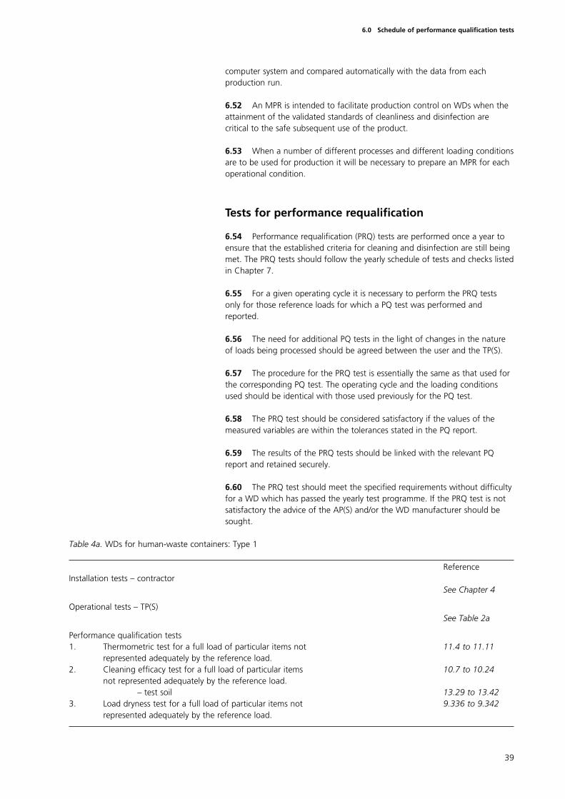
computer system and compared automatically with the data from eachproduction run.
6.52 An MPR is intended to facilitate production control on WDs when theattainment of the validated standards of cleanliness and disinfection arecritical to the safe subsequent use of the product.
6.53 When a number of different processes and different loading conditionsare to be used for production it will be necessary to prepare an MPR for eachoperational condition.
Tests for performance requalification
6.54 Performance requalification (PRQ) tests are performed once a year toensure that the established criteria for cleaning and disinfection are still beingmet. The PRQ tests should follow the yearly schedule of tests and checks listedin Chapter 7.
6.55 For a given operating cycle it is necessary to perform the PRQ testsonly for those reference loads for which a PQ test was performed andreported.
6.56 The need for additional PQ tests in the light of changes in the natureof loads being processed should be agreed between the user and the TP(S).
6.57 The procedure for the PRQ test is essentially the same as that used forthe corresponding PQ test. The operating cycle and the loading conditionsused should be identical with those used previously for the PQ test.
6.58 The PRQ test should be considered satisfactory if the values of themeasured variables are within the tolerances stated in the PQ report.
6.59 The results of the PRQ tests should be linked with the relevant PQreport and retained securely.
6.60 The PRQ test should meet the specified requirements without difficultyfor a WD which has passed the yearly test programme. If the PRQ test is notsatisfactory the advice of the AP(S) and/or the WD manufacturer should besought.
Table 4a. WDs for human-waste containers: Type 1
ReferenceInstallation tests – contractor
See Chapter 4
Operational tests – TP(S)See Table 2a
Performance qualification tests1. Thermometric test for a full load of particular items not 11.4 to 11.11
represented adequately by the reference load.2. Cleaning efficacy test for a full load of particular items 10.7 to 10.24
not represented adequately by the reference load.– test soil 13.29 to 13.42
3. Load dryness test for a full load of particular items not 9.336 to 9.342represented adequately by the reference load.
39
6.0 Schedule of performance qualification tests
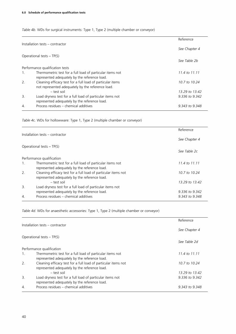
Table 4b. WDs for surgical instruments: Type 1, Type 2 (multiple chamber or conveyor)
ReferenceInstallation tests – contractor
See Chapter 4
Operational tests – TP(S)See Table 2b
Performance qualification tests1. Thermometric test for a full load of particular items not 11.4 to 11.11
represented adequately by the reference load. 2. Cleaning efficacy test for a full load of particular items 10.7 to 10.24
not represented adequately by the reference load. – test soil 13.29 to 13.42
3. Load dryness test for a full load of particular items not 9.336 to 9.342represented adequately by the reference load.
4. Process residues – chemical additives 9.343 to 9.348
Table 4c. WDs for hollowware: Type 1, Type 2 (multiple chamber or conveyor)
ReferenceInstallation tests – contractor
See Chapter 4
Operational tests – TP(S)See Table 2c
Performance qualification1. Thermometric test for a full load of particular items not 11.4 to 11.11
represented adequately by the reference load.2. Cleaning efficacy test for a full load of particular items not 10.7 to 10.24
represented adequately by the reference load.– test soil 13.29 to 13.42
3. Load dryness test for a full load of particular items notrepresented adequately by the reference load. 9.336 to 9.342
4. Process residues – chemical additives 9.343 to 9.348
Table 4d. WDs for anaesthetic accessories: Type 1, Type 2 (multiple chamber or conveyor)
ReferenceInstallation tests – contractor
See Chapter 4
Operational tests – TP(S)See Table 2d
Performance qualification1. Thermometric test for a full load of particular items not 11.4 to 11.11
represented adequately by the reference load. 2. Cleaning efficacy test for a full load of particular items not 10.7 to 10.24
represented adequately by the reference load. – test soil 13.29 to 13.42
3. Load dryness test for a full load of particular items not 9.336 to 9.342represented adequately by the reference load.
4. Process residues – chemical additives 9.343 to 9.348
40
6.0 Schedule of performance qualification tests
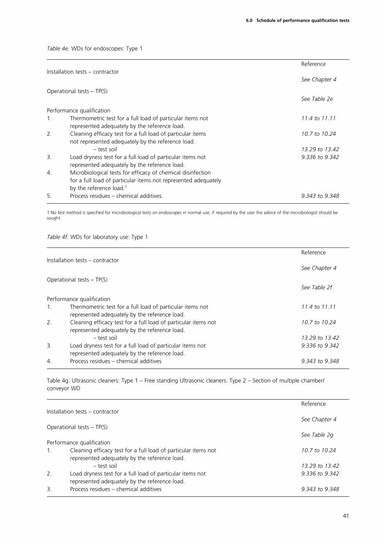
Table 4e. WDs for endoscopes: Type 1
ReferenceInstallation tests – contractor
See Chapter 4
Operational tests – TP(S)See Table 2e
Performance qualification1. Thermometric test for a full load of particular items not 11.4 to 11.11
represented adequately by the reference load. 2. Cleaning efficacy test for a full load of particular items 10.7 to 10.24
not represented adequately by the reference load. – test soil 13.29 to 13.42
3. Load dryness test for a full load of particular items not 9.336 to 9.342represented adequately by the reference load.
4. Microbiological tests for efficacy of chemical disinfection for a full load of particular items not represented adequately by the reference load.1
5. Process residues – chemical additives. 9.343 to 9.348
1 No test method is specified for microbiological tests on endoscopes in normal use; if required by the user the advice of the microbiologist should besought.
Table 4f. WDs for laboratory use: Type 1
ReferenceInstallation tests – contractor
See Chapter 4
Operational tests – TP(S)See Table 2f
Performance qualification1. Thermometric test for a full load of particular items not 11.4 to 11.11
represented adequately by the reference load. 2. Cleaning efficacy test for a full load of particular items not 10.7 to 10.24
represented adequately by the reference load.– test soil 13.29 to 13.42
3. Load dryness test for a full load of particular items not 9.336 to 9.342represented adequately by the reference load.
4. Process residues – chemical additives 9.343 to 9.348
Table 4g. Ultrasonic cleaners: Type 1 – Free standing Ultrasonic cleaners: Type 2 – Section of multiple chamber/conveyor WD
ReferenceInstallation tests – contractor
See Chapter 4Operational tests – TP(S)
See Table 2gPerformance qualification1. Cleaning efficacy test for a full load of particular items not 10.7 to 10.24
represented adequately by the reference load. – test soil 13.29 to 13.42
2. Load dryness test for a full load of particular items not 9.336 to 9.342represented adequately by the reference load.
3. Process residues – chemical additives 9.343 to 9.348
41
6.0 Schedule of performance qualification tests
Introduction
7.1 Periodic tests are carried out at daily, weekly, quarterly and yearlyintervals. They are the shared responsibility of the TP(S) and the user.
7.2 The yearly test schedule is identical to that required for revalidation. Itcontains the tests required for re-commissioning and for re-qualification of theperformance of the WD.
7.3 Tests should only be undertaken after completion of the plannedmaintenance tasks described in HTM 2030 ‘Operational management’.
7.4 The schedules for the tests are set out for each type of WD in Tables 5ato 5g inclusive.
7.5 Each test is cross-referenced to a detailed description of the testprocedure in Chapter 9. Unless otherwise specified in Chapter 9 the testsshould be carried out with the WD at normal working temperature, which mayrequire a ‘warm-up’ run to be carried out before commencement of testing.
7.6 A number of the tests required can be carried out concurrently on thesame operating cycle and this is also indicated in Chapter 9.
7.7 The results of periodic tests, whether carried out by the user or by theTP(S) should be filed securely, for example in the plant history file.
Weekly safety checks
7.8 The TP(S) should make the following safety checks before starting thesequence of weekly tests:
a. examine the door seal(s)
b. check the security and performance of door safety devices.
7.9 For WDs which include a pressure vessel or pressure system (forexample steam or compressed air) the following checks should be made:
a. that safety valves or other pressure limiting devices are free to operate;
b. make any other checks required by the competent person inconnection with the written scheme of examination for the pressurevessel.
Yearly safety checks
7.10 In order to ensure the continued safe functioning of the WD the TP(S)should conduct a series of safety checks before starting the yearly tests.
7.11 The AP(S) should draw up a documented programme of the yearlysafety checks necessary for a particular installation.
42
7.0 Schedule of periodic tests

7.12 The original installation checks and tests may be used as a basis for theyearly safety checks paying particular attention to those factors which affectsafety and especially to those which may have changed since the previousannual safety check (or installation test).
7.13 The adequacy and safe connection of all engineering services shouldbe verified.
43
7.0 Schedule of periodic tests
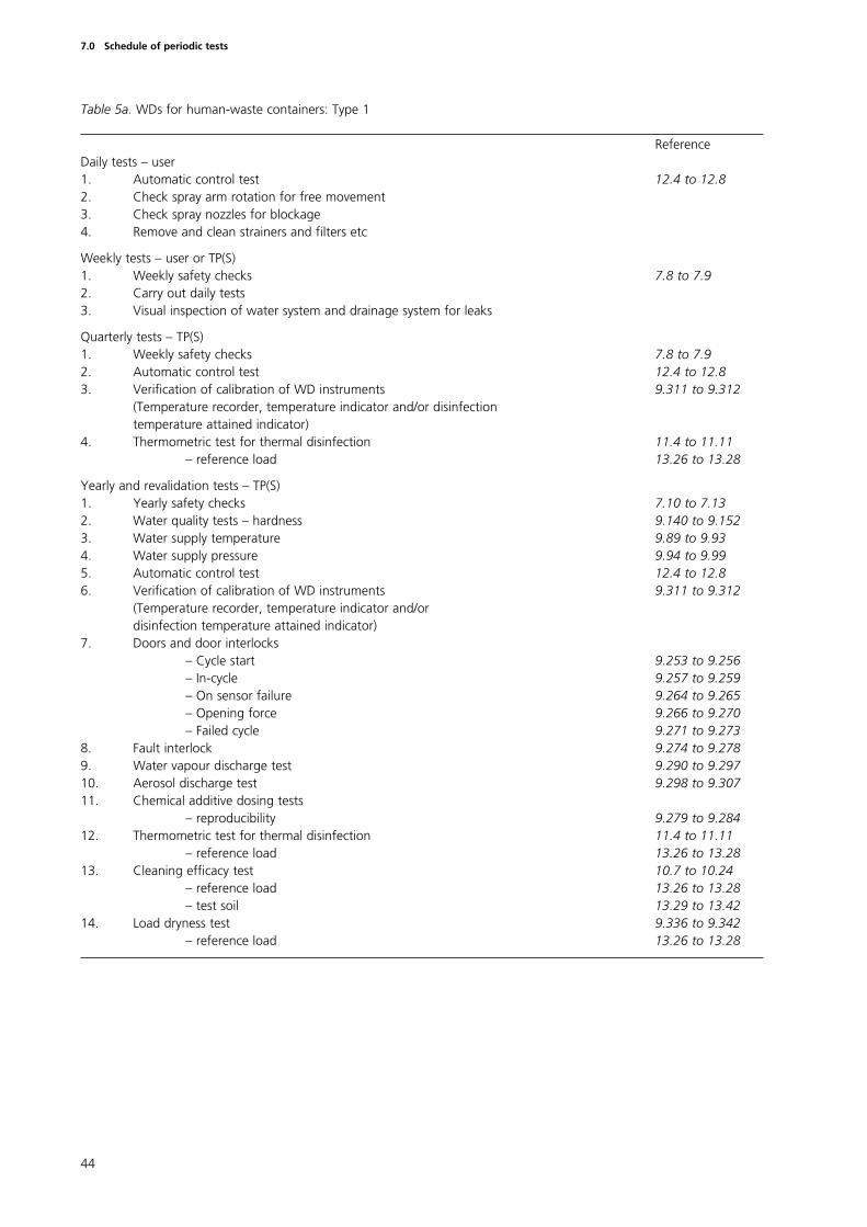
Table 5a. WDs for human-waste containers: Type 1
ReferenceDaily tests – user1. Automatic control test 12.4 to 12.82. Check spray arm rotation for free movement3. Check spray nozzles for blockage4. Remove and clean strainers and filters etc
Weekly tests – user or TP(S)1. Weekly safety checks 7.8 to 7.92. Carry out daily tests 3. Visual inspection of water system and drainage system for leaks
Quarterly tests – TP(S)1. Weekly safety checks 7.8 to 7.92. Automatic control test 12.4 to 12.83. Verification of calibration of WD instruments 9.311 to 9.312
(Temperature recorder, temperature indicator and/or disinfection temperature attained indicator)
4. Thermometric test for thermal disinfection 11.4 to 11.11– reference load 13.26 to 13.28
Yearly and revalidation tests – TP(S)1. Yearly safety checks 7.10 to 7.132. Water quality tests – hardness 9.140 to 9.1523. Water supply temperature 9.89 to 9.934. Water supply pressure 9.94 to 9.995. Automatic control test 12.4 to 12.86. Verification of calibration of WD instruments 9.311 to 9.312
(Temperature recorder, temperature indicator and/or disinfection temperature attained indicator)
7. Doors and door interlocks– Cycle start 9.253 to 9.256– In-cycle 9.257 to 9.259– On sensor failure 9.264 to 9.265– Opening force 9.266 to 9.270– Failed cycle 9.271 to 9.273
8. Fault interlock 9.274 to 9.2789. Water vapour discharge test 9.290 to 9.29710. Aerosol discharge test 9.298 to 9.30711. Chemical additive dosing tests
– reproducibility 9.279 to 9.28412. Thermometric test for thermal disinfection 11.4 to 11.11
– reference load 13.26 to 13.2813. Cleaning efficacy test 10.7 to 10.24
– reference load 13.26 to 13.28– test soil 13.29 to 13.42
14. Load dryness test 9.336 to 9.342– reference load 13.26 to 13.28
44
7.0 Schedule of periodic tests
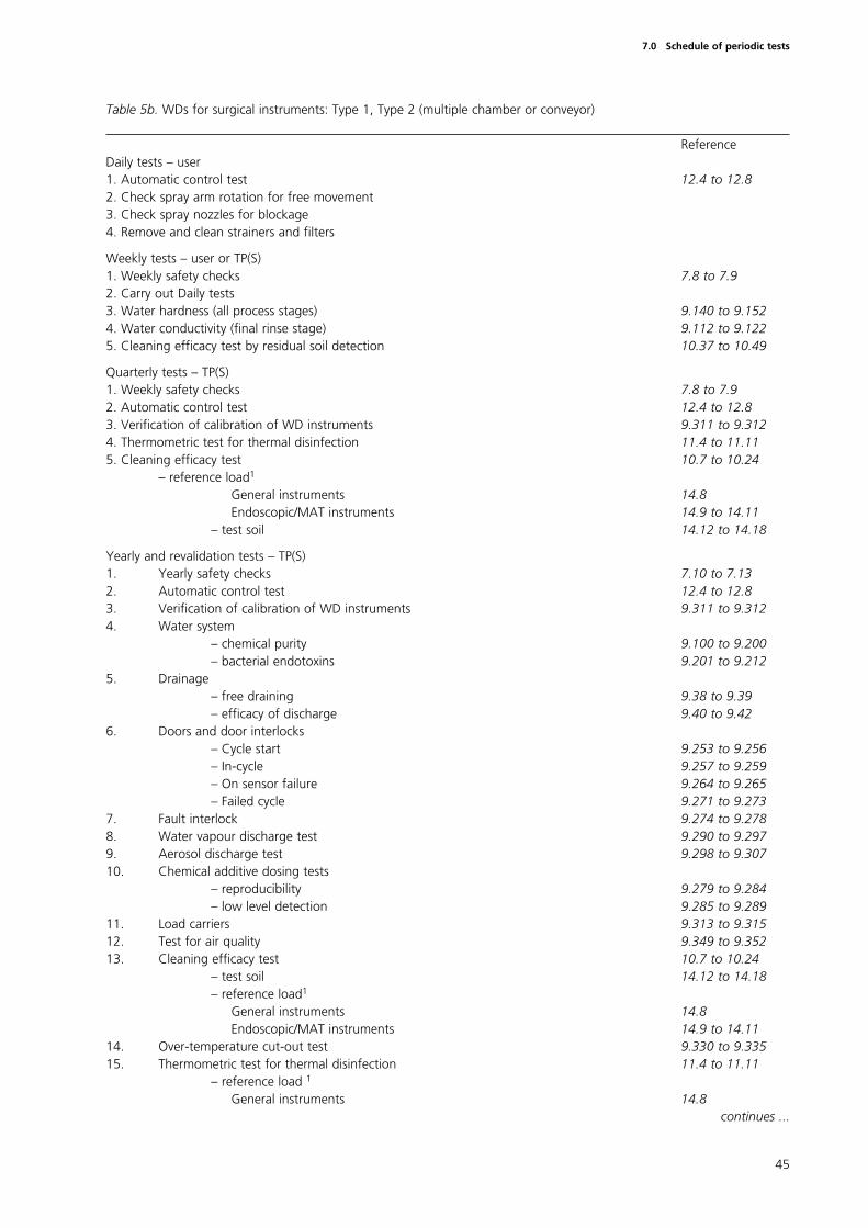
Table 5b. WDs for surgical instruments: Type 1, Type 2 (multiple chamber or conveyor)
ReferenceDaily tests – user1. Automatic control test 12.4 to 12.82. Check spray arm rotation for free movement3. Check spray nozzles for blockage4. Remove and clean strainers and filters
Weekly tests – user or TP(S)1. Weekly safety checks 7.8 to 7.92. Carry out Daily tests3. Water hardness (all process stages) 9.140 to 9.1524. Water conductivity (final rinse stage) 9.112 to 9.1225. Cleaning efficacy test by residual soil detection 10.37 to 10.49
Quarterly tests – TP(S)1. Weekly safety checks 7.8 to 7.92. Automatic control test 12.4 to 12.83. Verification of calibration of WD instruments 9.311 to 9.3124. Thermometric test for thermal disinfection 11.4 to 11.115. Cleaning efficacy test 10.7 to 10.24
– reference load1
General instruments 14.8 Endoscopic/MAT instruments 14.9 to 14.11
– test soil 14.12 to 14.18
Yearly and revalidation tests – TP(S)1. Yearly safety checks 7.10 to 7.132. Automatic control test 12.4 to 12.83. Verification of calibration of WD instruments 9.311 to 9.3124. Water system
– chemical purity 9.100 to 9.200– bacterial endotoxins 9.201 to 9.212
5. Drainage– free draining 9.38 to 9.39– efficacy of discharge 9.40 to 9.42
6. Doors and door interlocks– Cycle start 9.253 to 9.256– In-cycle 9.257 to 9.259– On sensor failure 9.264 to 9.265– Failed cycle 9.271 to 9.273
7. Fault interlock 9.274 to 9.2788. Water vapour discharge test 9.290 to 9.2979. Aerosol discharge test 9.298 to 9.30710. Chemical additive dosing tests
– reproducibility 9.279 to 9.284– low level detection 9.285 to 9.289
11. Load carriers 9.313 to 9.31512. Test for air quality 9.349 to 9.35213. Cleaning efficacy test 10.7 to 10.24
– test soil 14.12 to 14.18– reference load1
General instruments 14.8 Endoscopic/MAT instruments 14.9 to 14.11
14. Over-temperature cut-out test 9.330 to 9.33515. Thermometric test for thermal disinfection 11.4 to 11.11
– reference load 1
General instruments 14.8 continues ...
45
7.0 Schedule of periodic tests

Endoscopic/MAT instruments 14.9 to 14.1116. Load dryness test 9.336 to 9.342
– reference load1
General instruments 14.8 Endoscopic/MAT instruments 14.9 to 14.11
17. Process residues – chemical additives 9.343 to 9.348
1 Additional test loads and alternative test soils may be required for WDs which are also intended for use with hollowware and/or anaesthetic accessories(see Tables 2c, 2d, 3c, 3d, 4c and 4d and Chapters 15 and 16). The additional testing should also include tests on the load carriers that will be used withthese additional loads (9.313 to 9.315).
46
7.0 Schedule of periodic tests
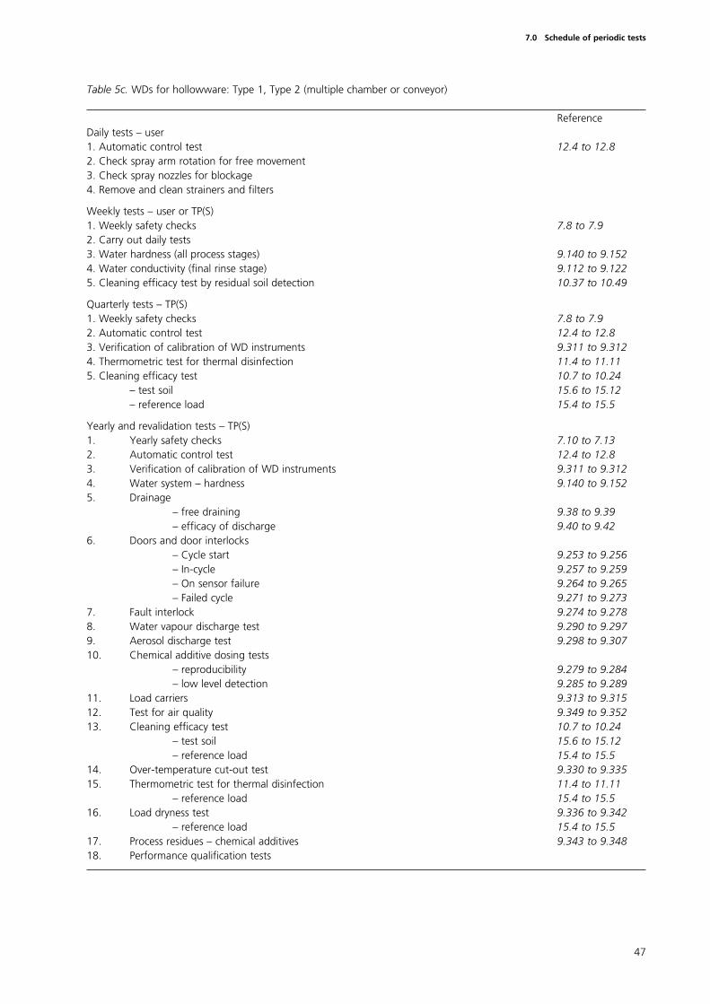
Table 5c. WDs for hollowware: Type 1, Type 2 (multiple chamber or conveyor)
ReferenceDaily tests – user1. Automatic control test 12.4 to 12.82. Check spray arm rotation for free movement3. Check spray nozzles for blockage4. Remove and clean strainers and filters
Weekly tests – user or TP(S)1. Weekly safety checks 7.8 to 7.92. Carry out daily tests3. Water hardness (all process stages) 9.140 to 9.1524. Water conductivity (final rinse stage) 9.112 to 9.1225. Cleaning efficacy test by residual soil detection 10.37 to 10.49
Quarterly tests – TP(S)1. Weekly safety checks 7.8 to 7.92. Automatic control test 12.4 to 12.83. Verification of calibration of WD instruments 9.311 to 9.3124. Thermometric test for thermal disinfection 11.4 to 11.115. Cleaning efficacy test 10.7 to 10.24
– test soil 15.6 to 15.12– reference load 15.4 to 15.5
Yearly and revalidation tests – TP(S)1. Yearly safety checks 7.10 to 7.132. Automatic control test 12.4 to 12.83. Verification of calibration of WD instruments 9.311 to 9.3124. Water system – hardness 9.140 to 9.1525. Drainage
– free draining 9.38 to 9.39– efficacy of discharge 9.40 to 9.42
6. Doors and door interlocks– Cycle start 9.253 to 9.256– In-cycle 9.257 to 9.259– On sensor failure 9.264 to 9.265– Failed cycle 9.271 to 9.273
7. Fault interlock 9.274 to 9.2788. Water vapour discharge test 9.290 to 9.2979. Aerosol discharge test 9.298 to 9.30710. Chemical additive dosing tests
– reproducibility 9.279 to 9.284– low level detection 9.285 to 9.289
11. Load carriers 9.313 to 9.31512. Test for air quality 9.349 to 9.35213. Cleaning efficacy test 10.7 to 10.24
– test soil 15.6 to 15.12– reference load 15.4 to 15.5
14. Over-temperature cut-out test 9.330 to 9.33515. Thermometric test for thermal disinfection 11.4 to 11.11
– reference load 15.4 to 15.516. Load dryness test 9.336 to 9.342
– reference load 15.4 to 15.517. Process residues – chemical additives 9.343 to 9.34818. Performance qualification tests
47
7.0 Schedule of periodic tests
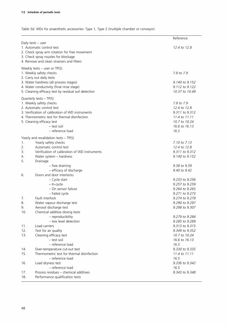
Table 5d. WDs for anaesthetic accessories: Type 1, Type 2 (multiple chamber or conveyor)
ReferenceDaily tests – user1. Automatic control test 12.4 to 12.82. Check spray arm rotation for free movement3. Check spray nozzles for blockage4. Remove and clean strainers and filters
Weekly tests – user or TP(S)1. Weekly safety checks 7.8 to 7.92. Carry out daily tests3. Water hardness (all process stages) 9.140 to 9.1524. Water conductivity (final rinse stage) 9.112 to 9.1225. Cleaning efficacy test by residual soil detection 10.37 to 10.49
Quarterly tests – TP(S)1. Weekly safety checks 7.8 to 7.92. Automatic control test 12.4 to 12.83. Verification of calibration of WD instruments 9.311 to 9.3124. Thermometric test for thermal disinfection 11.4 to 11.115. Cleaning efficacy test 10.7 to 10.24
– test soil 16.6 to 16.13– reference load 16.5
Yearly and revalidation tests – TP(S)1. Yearly safety checks 7.10 to 7.132. Automatic control test 12.4 to 12.83. Verification of calibration of WD instruments 9.311 to 9.3124. Water system – hardness 9.140 to 9.1525. Drainage
– free draining 9.38 to 9.39– efficacy of discharge 9.40 to 9.42
6. Doors and door interlocks– Cycle start 9.253 to 9.256– In-cycle 9.257 to 9.259– On sensor failure 9.264 to 9.265– Failed cycle 9.271 to 9.273
7. Fault interlock 9.274 to 9.2788. Water vapour discharge test 9.290 to 9.2979. Aerosol discharge test 9.298 to 9.30710. Chemical additive dosing tests
– reproducibility 9.279 to 9.284– low level detection 9.285 to 9.289
11. Load carriers 9.313 to 9.31512. Test for air quality 9.349 to 9.35213. Cleaning efficacy test 10.7 to 10.24
– test soil 16.6 to 16.13– reference load 16.5
14. Over-temperature cut-out test 9.330 to 9.33515. Thermometric test for thermal disinfection 11.4 to 11.11
– reference load 16.516. Load dryness test 9.336 to 9.342
– reference load 16.517. Process residues – chemical additives 9.343 to 9.34818. Performance qualification tests
48
7.0 Schedule of periodic tests
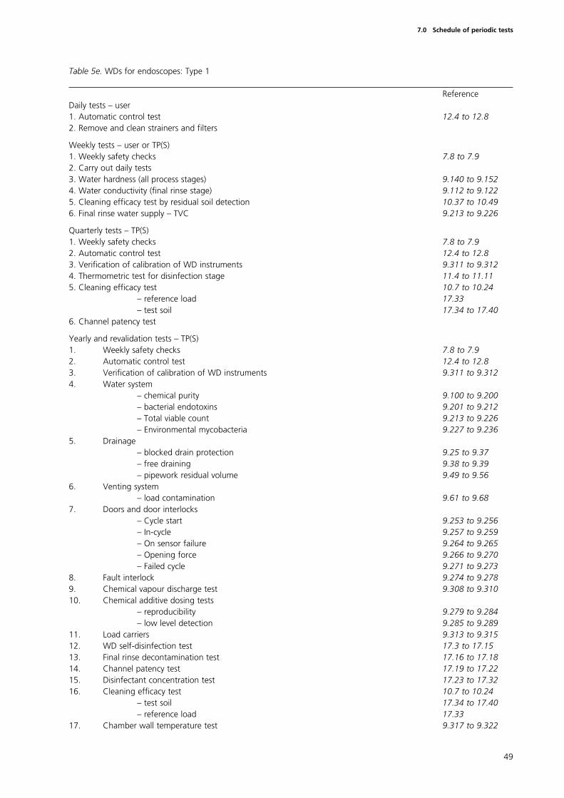
Table 5e. WDs for endoscopes: Type 1
ReferenceDaily tests – user1. Automatic control test 12.4 to 12.82. Remove and clean strainers and filters
Weekly tests – user or TP(S)1. Weekly safety checks 7.8 to 7.92. Carry out daily tests3. Water hardness (all process stages) 9.140 to 9.1524. Water conductivity (final rinse stage) 9.112 to 9.1225. Cleaning efficacy test by residual soil detection 10.37 to 10.496. Final rinse water supply – TVC 9.213 to 9.226
Quarterly tests – TP(S)1. Weekly safety checks 7.8 to 7.92. Automatic control test 12.4 to 12.83. Verification of calibration of WD instruments 9.311 to 9.3124. Thermometric test for disinfection stage 11.4 to 11.115. Cleaning efficacy test 10.7 to 10.24
– reference load 17.33– test soil 17.34 to 17.40
6. Channel patency test
Yearly and revalidation tests – TP(S)1. Weekly safety checks 7.8 to 7.92. Automatic control test 12.4 to 12.83. Verification of calibration of WD instruments 9.311 to 9.3124. Water system
– chemical purity 9.100 to 9.200– bacterial endotoxins 9.201 to 9.212– Total viable count 9.213 to 9.226– Environmental mycobacteria 9.227 to 9.236
5. Drainage– blocked drain protection 9.25 to 9.37– free draining 9.38 to 9.39– pipework residual volume 9.49 to 9.56
6. Venting system– load contamination 9.61 to 9.68
7. Doors and door interlocks– Cycle start 9.253 to 9.256– In-cycle 9.257 to 9.259– On sensor failure 9.264 to 9.265– Opening force 9.266 to 9.270– Failed cycle 9.271 to 9.273
8. Fault interlock 9.274 to 9.2789. Chemical vapour discharge test 9.308 to 9.31010. Chemical additive dosing tests
– reproducibility 9.279 to 9.284– low level detection 9.285 to 9.289
11. Load carriers 9.313 to 9.31512. WD self-disinfection test 17.3 to 17.1513. Final rinse decontamination test 17.16 to 17.1814. Channel patency test 17.19 to 17.2215. Disinfectant concentration test 17.23 to 17.3216. Cleaning efficacy test 10.7 to 10.24
– test soil 17.34 to 17.40– reference load 17.33
17. Chamber wall temperature test 9.317 to 9.322
49
7.0 Schedule of periodic tests
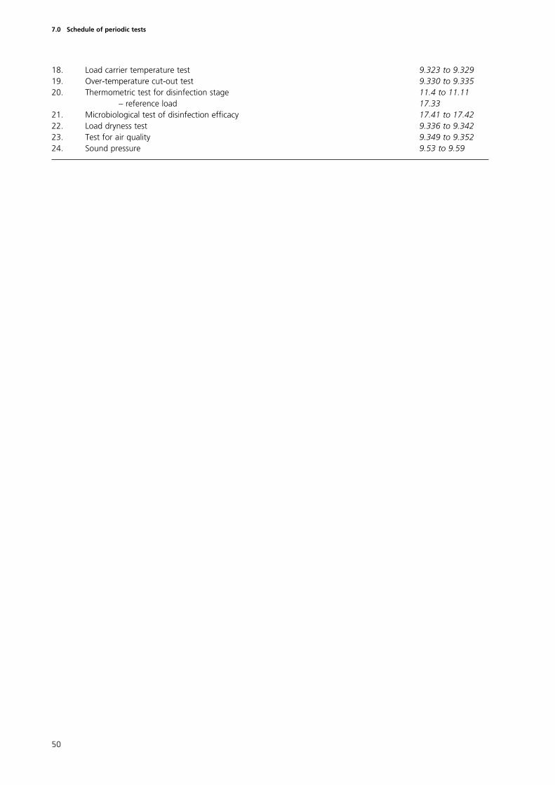
18. Load carrier temperature test 9.323 to 9.32919. Over-temperature cut-out test 9.330 to 9.33520. Thermometric test for disinfection stage 11.4 to 11.11
– reference load 17.33 21. Microbiological test of disinfection efficacy 17.41 to 17.4222. Load dryness test 9.336 to 9.34223. Test for air quality 9.349 to 9.35224. Sound pressure 9.53 to 9.59
50
7.0 Schedule of periodic tests
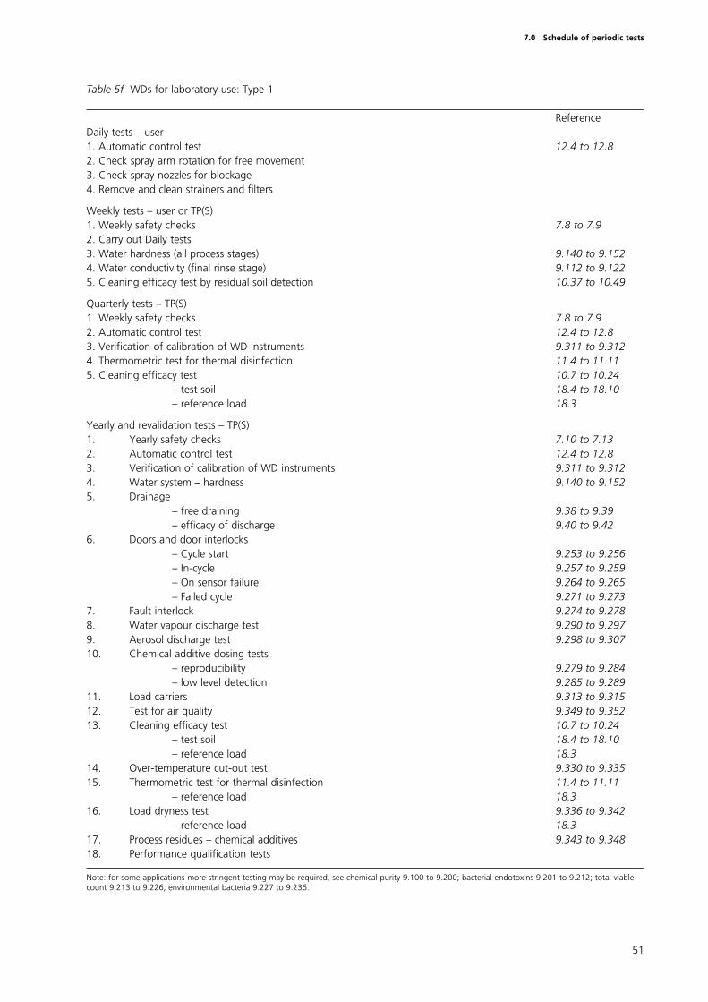
Table 5f WDs for laboratory use: Type 1
ReferenceDaily tests – user1. Automatic control test 12.4 to 12.82. Check spray arm rotation for free movement3. Check spray nozzles for blockage4. Remove and clean strainers and filters
Weekly tests – user or TP(S)1. Weekly safety checks 7.8 to 7.92. Carry out Daily tests3. Water hardness (all process stages) 9.140 to 9.1524. Water conductivity (final rinse stage) 9.112 to 9.1225. Cleaning efficacy test by residual soil detection 10.37 to 10.49
Quarterly tests – TP(S)1. Weekly safety checks 7.8 to 7.92. Automatic control test 12.4 to 12.83. Verification of calibration of WD instruments 9.311 to 9.3124. Thermometric test for thermal disinfection 11.4 to 11.115. Cleaning efficacy test 10.7 to 10.24
– test soil 18.4 to 18.10– reference load 18.3
Yearly and revalidation tests – TP(S)1. Yearly safety checks 7.10 to 7.132. Automatic control test 12.4 to 12.83. Verification of calibration of WD instruments 9.311 to 9.3124. Water system – hardness 9.140 to 9.1525. Drainage
– free draining 9.38 to 9.39– efficacy of discharge 9.40 to 9.42
6. Doors and door interlocks– Cycle start 9.253 to 9.256– In-cycle 9.257 to 9.259– On sensor failure 9.264 to 9.265– Failed cycle 9.271 to 9.273
7. Fault interlock 9.274 to 9.2788. Water vapour discharge test 9.290 to 9.2979. Aerosol discharge test 9.298 to 9.30710. Chemical additive dosing tests
– reproducibility 9.279 to 9.284– low level detection 9.285 to 9.289
11. Load carriers 9.313 to 9.31512. Test for air quality 9.349 to 9.35213. Cleaning efficacy test 10.7 to 10.24
– test soil 18.4 to 18.10– reference load 18.3
14. Over-temperature cut-out test 9.330 to 9.33515. Thermometric test for thermal disinfection 11.4 to 11.11
– reference load 18.316. Load dryness test 9.336 to 9.342
– reference load 18.317. Process residues – chemical additives 9.343 to 9.34818. Performance qualification tests
Note: for some applications more stringent testing may be required, see chemical purity 9.100 to 9.200; bacterial endotoxins 9.201 to 9.212; total viablecount 9.213 to 9.226; environmental bacteria 9.227 to 9.236.
51
7.0 Schedule of periodic tests
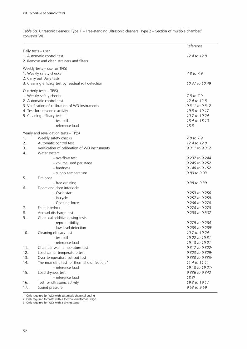
Table 5g. Ultrasonic cleaners: Type 1 – Free-standing Ultrasonic cleaners: Type 2 – Section of multiple chamber/conveyor WD
ReferenceDaily tests – user1. Automatic control test 12.4 to 12.82. Remove and clean strainers and filters
Weekly tests – user or TP(S)1. Weekly safety checks 7.8 to 7.92. Carry out Daily tests3. Cleaning efficacy test by residual soil detection 10.37 to 10.49
Quarterly tests – TP(S)1. Weekly safety checks 7.8 to 7.92. Automatic control test 12.4 to 12.83. Verification of calibration of WD instruments 9.311 to 9.3124. Test for ultrasonic activity 19.3 to 19.175. Cleaning efficacy test 10.7 to 10.24
– test soil 18.4 to 18.10– reference load 18.3
Yearly and revalidation tests – TP(S)1. Weekly safety checks 7.8 to 7.92. Automatic control test 12.4 to 12.83. Verification of calibration of WD instruments 9.311 to 9.3124. Water system
– overflow test 9.237 to 9.244– volume used per stage 9.245 to 9.252– hardness 9.140 to 9.152– supply temperature 9.89 to 9.93
5. Drainage– free draining 9.38 to 9.39
6. Doors and door interlocks– Cycle start 9.253 to 9.256– In-cycle 9.257 to 9.259– Opening force 9.266 to 9.270
7. Fault interlock 9.274 to 9.2788. Aerosol discharge test 9.298 to 9.3079. Chemical additive dosing tests
– reproducibility 9.279 to 9.284– low level detection 9.285 to 9.2891
10. Cleaning efficacy test 10.7 to 10.24– test soil 19.22 to 19.31– reference load 19.18 to 19.21
11. Chamber wall temperature test 9.317 to 9.3222
12. Load carrier temperature test 9.323 to 9.3292
13. Over-temperature cut-out test 9.330 to 9.3352
14. Thermometric test for thermal disinfection 1 11.4 to 11.11– reference load 19.18 to 19.212
15. Load dryness test 9.336 to 9.342– reference load 18.33
16. Test for ultrasonic activity 19.3 to 19.17 17. Sound pressure 9.53 to 9.59
1. Only required for WDs with automatic chemical dosing2. Only required for WDs with a thermal disinfection stage3. Only required for WDs with a drying stage
52
7.0 Schedule of periodic tests
Introduction
8.1 This chapter reviews the major items of portable test equipmentnecessary to carry out the test procedures described in this HTM.Specifications for instruments fitted permanently to WDs are given in therelevant British Standards and will be included in the forthcoming EuropeanStandards; they are discussed in HTM 2030 ‘Operational management’.
8.2 Instrumentation technology continues to advance rapidly making itincreasingly difficult and undesirable to provide detailed specifications for theequipment to be used in testing WDs. There is a clear trend towardscomputer controlled data loggers with software which enables the system toverify attainment of the required conditions and then to produce a detailedwritten report accompanied by tabulated or graphed data. Although thesenew systems may offer advantages in clarity of presentation, as well asreduced operator time, the traditional instruments, such as chart recorders,remain equally acceptable.
8.3 The objectives of this chapter are both to ensure that traditionalmeasurement methods are supported adequately and to define clearly theessential requirements that apply to the test equipment whether it is atraditional system or the latest technology.
8.4 When it is proposed to use measurement and/or recording techniquesthat are not covered in this HTM the advice of the AP(S) should be sought.
8.5 It has been assumed also that there will be ready access to standardlaboratory equipment and supplies.
Calibration and sources of error
8.6 Errors of measurement occur for a number of reasons. These includeinherent factors such as the design of the measuring equipment and otherproblems such as loose or imperfect connections and change in environmentaltemperature around the instrument. Variations in the sensors themselves, themethod of introducing the sensors into the WD and their location within theload may add to the error in the temperature measurement. Changes inconditions other than the one being sensed may also lead to errors, forexample temperature fluctuations within pressure sensing elements may leadto errors in pressure measurement.
8.7 Careful attention to detail including the location of the testinstruments, effective maintenance and the skill of personnel trained in theapplication, handling and use of the instruments are required to eliminate orminimise these errors. Systematic errors can be reduced by careful calibration.
8.8 Instruments should be subjected to a planned maintenance andcalibration programme in accordance with the instrument manufacturersrecommendations. Each instrument should be labelled with a calibration dateand a reference from which its current calibration status may be traced.
53
8.0 Test equipment and materials
8.9 The calibration of all test instruments should be verified yearly by usingreference instruments with a valid certificate of calibration traceable to anational standard. A history record should be kept for each instrument.
8.10 In use all electronic test instruments should be located in a positionprotected from draughts and not subjected to rapid temperature variations.Test instruments should be allowed a period of time to stabilise within theenvironment of the test site. The manufacturer’s instructions should befollowed.
Recorders
8.11 Test recorders are required to measure temperature in all types of WDand may also be required for the measurement of pressure, flow rates andhumidity. They should be designed for use with the appropriate sensors,independent of those fitted to the WD, as described later in this HTM. Most ofthe tests described in this HTM may be conducted with a single recordercombining both temperature and pressure functions showing both records onthe same chart or print-out. For WDs incorporating humidity control orhumidity monitoring of a hot air drying stage, the measurement of humidity isdesirable but not essential.
8.12 Analogue recorders should comply with the display requirements of BS3693. Recorders using a potentiometric system should comply with BS 5164.
8.13 Digital recorders (data loggers) have many advantages over traditionalpen recorders. Data may be presented graphically or as a listing of numericalvalues or as a combination of both. In many cases parts of the operating cyclecan be expanded and replotted for closer examination.
8.14 Digital recorders should have the facility to copy data onto tape or diskwhich can then be removed for secure storage. Software used with digitalrecorders should be developed under a quality system (such as BS EN ISO9001).
8.15 The detailed specification for a test recorder will depend upon therange of WDs with which it is to be used. The measurement system (recorderand sensors) should be capable of measuring cycle variables to an accuracyequal to, or greater than, the instruments fitted to the WD.
8.16 The accuracy with which a variable can be read from the recorder willbe affected not only by the sources of error discussed above but also by theprecision of the calibration, the scale range, the integration time, the samplinginterval and the intrinsic accuracy of the recorder. Digital instruments mayregister measurements with a precision greater than the accuracy of thesystem as a whole and care needs to be taken with the interpretation of suchmeasurements.
8.17 The accuracies quoted by recorder manufacturers are measured undercontrolled reference conditions and do not include the errors from connectedsensors. Temperature measurement errors due to ambient temperaturechanges should not exceed 0.04ºC per ºC rise.
54
8.0 Test equipment and materials
Temperature measurement
Temperature sensors
8.18 Temperature sensors should be used to sense the temperature inlocations specified in the tests described in this HTM. The sensors should beeither platinum resistance elements and comply with IEC 751 Class A orthermocouples and comply with the relevant international table specified inIEC 584 Tolerance Class 1.
8.19 The performance characteristics of the temperature sensor should notbe adversely affected by the environment in which it is placed, eg pressure,hot detergent solution etc.
8.20 In order to avoid undue disturbance of the system being measured themajor diameter of the temperature sensors and their connecting leads whichwill be located within the WD should not exceed 2 mm.
Thermometric recording instrument(s)
8.21 One or more thermometric recording instruments should be used inconjunction with the temperature sensors to record the temperaturesmeasured in the locations specified in the tests described in this HTM. Theymay also be used to verify the readings obtained from instruments fitted tothe WD.
8.22 The recording instrument(s) should record the temperature from aminimum of three temperature sensors. The channels may be multiplexed orindependent of one another. The data recording rate for each channel shouldnot exceed 2.5 s. All data sampled should be used for the interpretation ofresults.
8.23 The scale range should include the expected maximum and minimumvalues of the cycle variables throughout the operating cycle with sufficientallowance for any deviations resulting from a malfunctioning WD. This shouldnormally include at least the range 10ºC to 110ºC.
8.24 In some WDs the air temperature close to the heater bank during thedrying stage may considerably exceed the upper limit of the air dryingtemperature.
55
8.0 Test equipment and materials
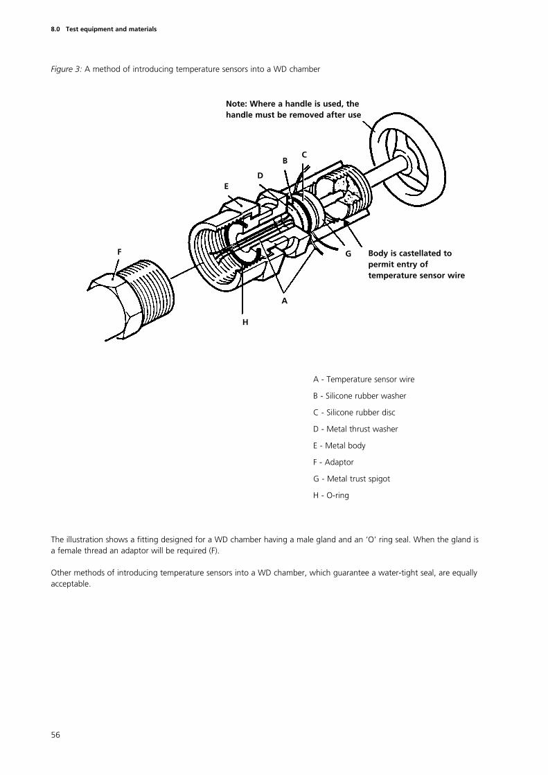
Figure 3: A method of introducing temperature sensors into a WD chamber
56
8.0 Test equipment and materials
A - Temperature sensor wire
B - Silicone rubber washer
C - Silicone rubber disc
D - Metal thrust washer
E - Metal body
F - Adaptor
G - Metal trust spigot
H - O-ring
The illustration shows a fitting designed for a WD chamber having a male gland and an ‘O’ ring seal. When the gland isa female thread an adaptor will be required (F).
Other methods of introducing temperature sensors into a WD chamber, which guarantee a water-tight seal, are equallyacceptable.
A
H
G
CB
DE
F Body is castellated topermit entry oftemperature sensor wire
Note: Where a handle is used, thehandle must be removed after use
8.25 The most critical stage of the WD operating cycle is the disinfectionstage. It is during this period that the values of the cycle variables are at theirmost critical and the recorder should be capable of measuring them tosufficient accuracy to confirm that the disinfection conditions have beenattained. The criteria are as follows.
a. For digital recorders, the sampling interval should be short enough forthe holding time to contain at least five independent measurements ineach recording channel.
b. The response time of the recorder should be short enough to enablethe output to follow significant fluctuations in the cycle variables and toensure that successive measurements are independent of each other. Itshould not be longer than the sampling interval.
c. The recorder must be accurate enough to show clearly whether themeasured temperatures are within the disinfection temperature band.The repeatability of the recorder should be ± 0.5ºC or better and thelimit of error of the complete measurement system including sensorsshould be no more than 1.0ºC when tested in an ambient temperatureof 20ºC ± 3K. The additional error due to changes in environmentaltemperature should not exceed 0.04 K/K.
d. For analogue instruments the minor mark interval should not exceed 1Kand the chart speed should be not less than 10 mm per minute. Theresolution should be not less than 0.5 K. Digital instruments shouldregister and record in increments of not more than 0.1 K.
Use of sensors
8.26 WDs conforming to BS 2745 are equipped with thermocouple entryglands of the same type as those used on sterilizer chambers. A typicalmethod of introducing sensors into the chamber is shown in Figure 3.
8.27 In older machines, having no dedicated entry port, entry may be madevia a tee which can usually be inserted into a service entry pipe to thechamber (for example the water supply pipe). Sensors should not beintroduced through a door seal.
8.28 Many of the tests require a sensor to be placed at the reference pointspecified by the manufacturer as representative of the conditions prevailingthroughout the chamber and load. This will usually be in the drain or sump ofthe chamber and will often be adjacent to the sensor used for the automaticcontroller.
8.29 The sensors may often be placed in positions where they aresubmerged for most of the cycle. Under these conditions water may migratealong the wire between the cores and the outer insulation sheath. To preventdamage to the recorder the outer sheath should either be punctured orstripped back a few centimetres from the end connected to the recorder toallow droplets of water to fall clear of the recorder.
8.30 Sensors used to monitor the temperature of load items and thechamber walls should be held securely in good thermal contact with theregion to be monitored using high temperature masking tape or autoclaveindicator tape.
For the shortest holding timerecommended (1 second at 90ºC)this would correspond to asampling interval of 0.2 second.However it is suggested that theminimum exposure time set shouldbe not less than 12 seconds forwhich a sampling interval of 1 second is then appropriate. For pen recorders the chart speedshould be fast enough to allowfluctuations on that scale to beclearly resolved. The duration of theholding time should be measurableto within ±10%.
57
8.0 Test equipment and materials
Calibration
8.31 Calibration should be carried out in accordance with the instrumentmanufacturers instructions by a validated method using a working or referencestandard which is traceable to a national standard.
8.32 The instrument should have a valid test certificate and the calibrationdata should include a temperature within the disinfection temperature band.
8.33 Before and after each series of tests on a WD the temperaturerecording system should be verified by comparison with an independenttemperature reference source at a temperature within the disinfectiontemperature band.
8.34 The temperature measured by all temperature sensors when immersedin a temperature source at a temperature known within ± 0.1K and within thedisinfection temperature band should not differ by more than 0.5K aftercalibration and adjustment.
Self-contained systems
8.35 Temperature measuring systems involving the use of leads from thesensing point within the load to an external measuring instrument are difficultor impractical to use within several designs of WD, for example continuousprocess machines consisting of several interconnecting cabins which areseparated by intermediate doors during processing.
8.36 A number of different designs of small self-contained single channeldata loggers for the measurement of temperature are commercially available.They are independently powered, may be programmed to take readings at therequired rate for the required duration and are downloaded onto a personalcomputer on completion of the data logging period. Those housed inprotective cases rated at IP68 are suitable for inclusion in washing machines.
8.37 Care needs to be taken in selecting units which are capable ofwithstanding the high temperature which may be found during the thermaldisinfection stage (≥ 90ºC) and drying stage (≥ 105ºC) of the cycle since manyof these devices are powered by batteries which will not withstandtemperatures above approximately 75ºC.
8.38 Data loggers with an external probe may be housed in an insulatedwater proof container through which the lead to the sensor passes by meansof a leak tight gland. A 25 mm thick layer of mineral wool insulation on allsurfaces of a datalogger contained within a 1000 ml screw top polypropylenejar has proved suitable.
8.39 The accuracy obtainable from these units is rarely to the standardspecified for conventional temperature recorders but the limit of error shouldnot exceed ± 0.8ºC when tested over the range 0ºC to 100ºC at an ambienttemperature of 20ºC ± 3K. The additional error due to changes inenvironmental temperature should not exceed 0.04 K/K instruments shouldregister and record in increments of not more than 1K.
8.40 The device should be capable of recording the sensed temperature atleast every 1 second and should be capable of storing not less than 1800records.
58
8.0 Test equipment and materials
8.41 For continuous process WDs not less than three such devices will beneeded together with a conventional temperature recorder.
Pressure measurement
8.42 Pressure may be required to be measured over the range fromatmospheric to 10 bar (for example for the water supply pressure). Differentialpressure of 1 –100 hectoPascals may be required to be measured (for examplefor the determination of the pressure drop across filters).
Transducers
8.43 Transducers for use with pressure recorders should conform with BS 6447, be suitable for the purpose and be of an accuracy equal to, or betterthan, the gauges specified below. The natural frequency of the sensor andconnected tubing should be not less than 10Hz and the time constant forrising pressure (0–63%) should be not greater than 0.04 seconds.
Gauges
8.44 Pressure gauges are required when the pressure recorder is unsuitableor for verifying the calibration of pressure instruments fitted to the WD.
8.45 Three gauges will normally be required to cover the whole pressurerange for all WDs and these are shown in Table 6.
8.46 Pressure gauges should be temperature compensated and except forthe differential pressure gauge be Bourdon-tube gauges conforming to BS837 Part 1 of nominal size 150 mm and accuracy class 0.25 (that is, the airshould not exceed 0.25% FSD).
Table 6 Requirements for pressure measurement
Scale range Mark Calibration Applicationinterval
0–100 kPa 1 kPa Liquid Differential pressureacross water filters
Flow through endoscopes
0–1000 kPA 5 kPa Liquid Water supply pressure
Recirculating pump pressure
0–50 kPa 1 kPa Air Differential pressureacross air filter
8.47 Gauges should be tested yearly by a recognised testing laboratory asdescribed in paragraph 5.2.1 of BS 1780.
8.48 The measurement of differential pressure across air filters may bemade with an inclined water manometer.
59
8.0 Test equipment and materials
8.49 The recorder for pressure measurement should have an overall limit oferror no more than 1% of the maximum specified operating pressure.
Flow measurement
Water
8.50 The volume of water used for each stage of the operating cycle may bemeasured using a water meter complying with ISO 4064 Part 1 Class A.
8.51 The meter should be designed to operate at temperatures up to 90ºCwith a supply pressure up to 16 bar.
8.52 The meter should have a minimum scale division of 0.1 litres or less andbe designed to measure flow rates over the range 1 litre per minute to 25 litres per minute.
8.53 A single jet turbine system is sufficiently accurate for the purpose.Other systems such as multi-jet turbine or semi-positive displacementsystems complying with ISO 4064 Part 1 Class B or Class C, or BS 5728 Class D, may also be used.
8.54 The calibration of the meter should be verified by determining theindicated volume flowing to a collecting vessel and comparing this with thecollected volume which may be determined by gravimetric or volumetricmeasurement.
Chemical additives
8.55 The volume of chemical additive used for each stage of the operatingcycle may be measured using a flow meter. There are a number ofcommercially available flow sensors designed to monitor flows in the range 0 to 2 litres/minute which are suitable for interfacing to a recorder ordatalogger.
8.56 The sensor should be suitable for use with fluids having viscosity inthe range 0.8 to 20 centiStokes and should be calibrated for the viscosity ofthe fluid to be measured.
8.57 The sensor should be designed to operate at temperatures up to70ºC with a supply pressure up to 10 bar.
8.58 The meter/recorder should have a minimum scale division of 10 millilitres or less and be designed to measure flow rates over the range 50 ml/min to 1500 ml/min.
8.59 The system should have an accuracy of ± 2.5% of full scale or better.
8.60 The calibration of the meter should be verified by determining theindicated volume flowing to a collecting vessel and comparing this with thecollected volume determined by gravimetric or volumetric measurement.
A meter of the rotating vane typecalibrated using water at 20ºC as theflowing medium and thensubsequently used to measure theflow of a detergent solution with aviscosity of 30 centiStokes would havean error of 15 to 20% if no correctionwas applied.
When the meter is connected inthe pipe there will be a noticeablepressure drop across the meter.Although this should be less than 1 bar it may interfere with thenormal operation of the WD andtherefore should not be usedduring tests for other characteristicsthan the volume of water used.
60
8.0 Test equipment and materials
Volume measurement
8.61 The volume of chemical additives and the volume of water used ineach stage are critical variables in the control of the washing-disinfectingprocess.
8.62 The volume used may be measured directly by collection in agraduated vessel of appropriate size.
8.63 Alternatively, for liquids of known density, the volume may bedetermined by collection in an appropriate size vessel of known mass (empty),determination of the mass of the vessel and contents, calculation of the massof the liquid and hence (by dividing this volume by the density) calculating thevolume of liquid.
8.64 Whichever method is used, the accuracy should be such that the erroris less than ± 2%.
8.65 Volumetric measuring containers complying with BS 5898: 1980 (ISO 384: 1978) are suitable.
Humidity measurement
8.66 Humidity is one of the cycle variables that may be used to control thedrying stage on WDs of various types. The level of humidity in the chamberand load at the end of the drying stage is ideally measured during validationby test instruments calibrated for relative humidity (RH) at atmosphericpressure. The accuracy of measurement should not be less than ± 10% RHover the range 30 to 80% RH.
8.67 There is no British Standard for humidity sensors but it isrecommended that the test sensors should function at temperatures of 10ºC to 100ºC and at pressures up to 2 bar absolute.
Other instruments
Sound level meter
8.68 An integrating sound level meter is required for the sound pressuretest. It should comply with Type 2 of BS 6698 (BS EN 60804: 1994specification for integrating-averaging sound level meters). Ten microphonesare required for the test on a single WD.
Balance
8.69 A laboratory balance may be required for load dryness tests and forcalibration of flow meters (for measuring the flow of water and/or chemicaladditives). It should be capable of measuring the mass of loads up to 4 kg toan accuracy of 0.1g and up to 400 g to an accuracy of 0.01 g.
8.70 An analytical balance is required for determination of the TotalDissolved Solids (Evaporative residue) in feed water. It should be capable ofmeasuring a mass of up to 100 g with an accuracy of 0.1 mg.
61
8.0 Test equipment and materials
62
8.0 Test equipment and materials
Gas monitoring equipment
8.71 A gas monitoring instrument is required for tests on WDs usingchemical additives which have a significant vapour pressure and are a potentialrisk.
8.72 The nature of the instrument will depend on the substance to bemonitored. In case of doubt advice should be sought from the manufacturer ofthe chemical additive or the AP(S).
8.73 The scale range of the measuring instrument should include theappropriate short term exposure limit or occupational exposure limit andextend to at least ten times that exposure limit.
Aerosol generator
8.74 An aerosol generator is required for tests on WDs incorporating airfilters intended to deliver air free from micro-organisms.
8.75 The device should be capable of generating a polydisperse aerosol withparticles having the size distribution shown in Table 7.
Particle counting photometer
8.76 A particle counter is required for tests on WDs incorporating air filtersintended to deliver air free from micro-organisms. The device should besuitable for estimation for comparison of mass concentration of airborneparticles as defined in Table 7.
8.77 It should have an accuracy of better than ±5% over the range of a five-expandable, six-decade resolution (that is 0.01% to 100% of the test cloud) asspecified in Appendix C of BS 5295 Part 1.
8.78 The photometer should have a minimum threshold sensitivity of 0.0001µg.l-1 and should be capable of measuring aerosol concentration in the range80-120 µg.l-1.
8.79 The sampling flow rate should be 0.40 ± 0.05 l s-1 and sampling shouldbe via a suitable probe.

63
8.0 Test equipment and materials
Table 7 Particle size distribution for aerosol generator
Particle size Fraction %µm by mass
< 0.5 > 20< 0.7 > 50< 1.0 > 75
Source: BS 5295 Part 1
64
9.1 This chapter discusses general principles and methods that are used inthe tests described in this HTM.
Terminology
9.2 For the purposes of this HTM the following definitions have beenadopted.
Cycle variables
9.3 The cycle variables are the physical and chemical properties such astime, temperature, pressure, flow rate, concentration, chemical compositionthat influence the efficacy of the cleaning and disinfection processes. Many ofthe test described in this HTM require the values of cycle variables to bedetermined experimentally and then compared with specified or standardvalues.
9.4 An indicated value is that shown by a visual display fitted to the WD.
9.5 A recorded value is that shown on the output of a recordinginstrument fitted permanently to the WD.
9.6 A measured value is that shown on a test instrument, for example atemperature recorder attached to the WD for test purposes.
9.7 A noted value is that written down following personal observation ofan indicated, recorded or measured value.
Disinfection conditions
9.8 Most operating cycles have a stage in which the load is exposed to thedisinfection conditions for a specified length of time. This period is known asthe holding time.
9.9 The disinfection conditions are the ranges of the cycle variableswhich may prevail throughout the chamber and load during the holding time.
9.10 The holding time is preceded by a period in which the disinfectionconditions are present in the chamber but have yet to be attained throughoutthe load. This is known as the equilibration time.
9.11 Together the equilibration time and the holding time constitute theplateau period. The plateau period can always be determined from theindicated or recorded temperature in the chamber during each cycle. Theequilibration and holding times cannot be ascertained unless the temperaturein that part of the load which is slowest to reach temperature is also beingmeasured.
9.0 Testing methods
65
9.12 For thermal (moist heat) disinfection the disinfection conditions arespecified by a disinfection temperature band, defined by a minimumacceptable temperature, known as the disinfection temperature, and amaximum allowable temperature.
9.13 The higher the disinfection temperature the shorter the holding timewhich will be required to achieve the same level of disinfection (see Table 3).
9.14 For liquid chemical disinfection, the disinfection conditions arespecified by a disinfection temperature band and a disinfectant contactconcentration range. The disinfection temperature band is defined by aminimum acceptable temperature, known as the disinfection temperature anda maximum allowable temperature. The disinfectant contact concentration isspecified by the minimum acceptable concentration in contact with the loadto be disinfected and the maximum allowable concentration.
9.15 For those WDs in which the chemical disinfection stage isthermostatically controlled at elevated temperature, the duration of theexposure to chemical germicide may be determined thermometrically. In mostcases, investigation of the performance of chemical disinfection processes canonly be carried out successfully using microbiological test methods inconjunction with physical testing.
9.16 The disinfection temperature band may also be quoted for liquidchemical disinfection/sterilization processes but is not a complete specificationof the disinfection conditions since the efficacy of such processes dependsalso on the concentration of the chemical agent.
Drainage
Drain seal integrity
Introduction
9.17 When it is impractical to vent the WD externally a condenser may beused to allow venting into the workspace without discharging hot, humid air.The restricted flow associated with this system may produce a back pressurein the chamber. If the back pressure is excessive the water seal between thechamber and drain may be broken.
9.18 The test is designed to establish that the seal integrity is maintainedunder normal operating conditions. The test is intended for use both as a typetest (and as such is a requirement of BS 2745: Part 2: 1993, Annex B) and asan operational or installation test.
Equipment
9.19 The following equipment is necessary:
• a full load of the type the WD is designed to process;
• a test trap, of the same type and dimensions as normally fitted, butmanufactured from a transparent material (Type test only).
9.0 Testing methods
66
Method for Type test
9.20 The transparent tap is fitted in place of the normal trap and connectedto a suitable outlet. Sufficient water is poured into the chamber to charge thetrap to the normal level. Verify that there are no leaks.
9.21 A full load is placed in the chamber, the door closed and an operatingcycle initiated. Without opening the door between cycles a further four cyclesare run. During each operating cycle observe the trap and establish whetherthe water seal in the trap has been broken.
Method for operational test
9.22 The test is carried out on the installed WD with all services connected.Verify that the trap is charged with water to the normal working level.
9.23 A full load is placed in the chamber, the door closed and an operatingcycle initiated. At the end of the cycle remove the load and examine the waterlevel in the trap. This may be done either visually or using a dipstick asappropriate. Without any delay which would allow the chamber or load tocool reload the machine with the same full load and run a further cycle.Repeat the same procedure until five consecutive cycles have been run. Aftereach operating cycle observe the trap and establish whether the water seal inthe trap has been broken.
Results
9.24 The water seal should not be broken during the test.
Blocked drain protection
Introduction
9.25 In the event that the drain from the chamber of the WD becameblocked continued operation of the WD would allow water and suspended soilto be discharged onto the floor either during the operating cycle or, forcabinet type WDs with sealed door(s), by sudden discharge when the door isopened at the end of the cycle.
9.26 The purpose of blocked drain protection is to prevent unacceptablespillage and minimise the risk of cross-infection.
9.27 In the test the drain is deliberately blocked and successive operatingcycles are run until the water level is above the level of the door seal. The testis intended for use both as a type test (and as such is a requirement of BS2745 Part 2 1993) and as an operational or installation test.
Equipment and materials
9.28 A solid metal sphere of diameter 10% to 15% greater than the internaldiameter of the trap or similar means of obstructing the discharge from thedrain is necessary.
9.0 Testing methods
67
Method for WDs with sealed doors
9.29 Introduce the metal sphere (or equivalent device) to block the drain.
9.30 Close the door and start the operating cycle. On completion of theoperating cycle attempt to open the WD door using the normal releaseprocedure.
9.31 If the door opens and the water level is below the door seal close thedoor and start another operating cycle.
9.32 Repeat the operating cycle as many times as necessary for either thewater level at the end of the cycle to be above the level of the door seal or fora fault to be indicated.
Method for WDs without sealed doors
9.33 Introduce the metal sphere (or equivalent device) to block the drain.
9.34 Start the operating cycle. On completion of the operating cycle if nowater has been spilled from the WD and no fault has been indicated startanother operating cycle.
9.35 Repeat the operating cycle as many times as necessary for either waterto be spilled from the WD or for a fault to be indicated.
Results for WDs with sealed doors
9.36 A fault should be indicated on, or before, the water level in thechamber reaching the level of the door seal. The door should not be capableof being opened by the normal release procedure; a tool, key or code shouldbe required.
Results for WDs without sealed doors
9.37 A fault should be indicated before water is spilled from the WD andthe operating cycle should be stopped preventing further inflow of water. Atool, key or code should be required to restart the WD.
Free draining (Tanks, chamber, load carriers, pipework)
Introduction
9.38 Residual water that does not drain from the internal pipework of theWD may provide an environment for microbial growth; these micro-organismsmay then be available to re-contaminate the disinfected load.
9.39 The following checks should be carried out during Type testing, workstesting and Installation testing to verify that as designed, built and installedthe WD will effectively discharge all the water from the system.
(i) Free draining of chamber and load carriers–test by visual observation at end of the cycle;
(ii) Free draining of tanks– test by visual observation on draining the tanks;
9.0 Testing methods
68
(iii) Pipework flow to discharge point– test by visual observation including use, when necessary, of aspirit level.
Purging of the trap (Type test only)
Introduction
9.40 The British Standard for WDs for human-waste containers requires thatthe mean volume of water discharged in each operating cycle shall exceed 15litres and that on completion of the washing stage of the operating cycle thetrap shall be clear of waste and soil.
9.41 The test method for determination of the volume of waterdischarged is described in BS 2745: Part 2: 1993 Annex D.
9.42 An alternative test method, applicable to all types of WD, isdescribed in paragraphs 9.43 to 9.48.
Efficacy of discharge through the trap
Introduction
9.43 The test is intended to verify that the operating cycle is effective inpurging the trap of all waste and soil.
Equipment and materials
9.44 The following equipment and materials are necessary.
a. test soil appropriate to the type of WD being tested (see Chapter10);
b. sampling tube of sufficient length to reach the water trap in the drainof the WD and a sampling pump (for example a pipette pump orsyringe).
Method
9.45 The test may be carried out as part of the cleaning efficacy test duringoperational testing.
9.46 On completion of an operating cycle to test the cleaning efficacy byprocessing a full load contaminated with an appropriate test soil place thesampling tube into the water trap and remove a sample for examination.
9.47 Examine the water sample from the trap for residual test soil using thedetection method appropriate to the test soil.
Results
9.48 The water in the trap should be free from residual soil at the same levelof detection as that specified for the load items.
Residual soil in the trap may presentan infection or recontaminationhazard.
In other European countries greatemphasis is placed on minimising thevolume of water used and it isunlikely that this requirement will beincluded in a European standard forWDs for human-waste containers.
9.0 Testing methods
Estimation of dead volume of pipework
Introduction
9.49 Residual water that does not drain from the internal pipework of theWD may provide an environment for microbial growth; these micro-organismsmay then be available to re-contaminate the disinfected load.
9.50 The test is intended primarily as a Type test but may also be of value asan operational test or when investigating microbial contamination occurring ina WD.
9.51 The test should only be carried out after completion of the checks forfree drainage described in paragraphs 9.38 to 9.39 have been satisfactorilycompleted.
Equipment
9.52 Volumetric measuring vessels of appropriate size are necessary.
Method
9.53 The pipework of the WD which is known to be dry (either followingdisassembly and re-assembly or purging with dry compressed air for not lessthan 30 minutes) is flushed with a known volume of water (simulating theflow that would occur in normal use).
9.54 The volume of water flushed through the system should be twice thatdetermined as the volume used per operating cycle (see paragraphs 9.201 to9.212) The volume of water discharged is measured and the dead volume,estimated as the volume retained, calculated from the difference between thetwo values.
9.55 When the WD has two or more pipework systems which are entirelyseparate (for example for flushing water, wash water, rinse water, chemicaldisinfectant solution) each system may be tested separately.
Results
9.56 The volume of retained water should be less than 1% of the volume ofwater used.
Venting system
Steam venting
Introduction
9.57 For WDs in which the load is heated and/or thermally disinfected bysteam heating the chamber should be protected against a rise in pressureabove the designed working pressure of the chamber and any discharge ofsteam should be only from the vent provided.
For WDs with chemical disinfectionsystems the retained volume in thepipework providing the final rinsevolume should be, as nearly aspossible, zero.
69
9.0 Testing methods
Equipment
9.58 A pressure gauge is necessary (if the WD chamber is not alreadyequipped with a pressure gauge in a known state of calibration).
Method
9.59 Close and seal the chamber of the WD in the manner specified by themanufacturer and start an operating cycle. Over-ride the automatic controllerto allow the continuous admission of steam to the chamber. Observe wheresteam is vented. Note the maximum value obtained on the pressure gauge.
Results
9.60 Steam discharge should occur solely through the vent. The noted valuefor the pressure within the chamber should not exceed the specified workingpressure or, for a chamber designed to work at atmospheric pressure, 200mbar (gauge).
Load contamination from ductwork
Introduction
9.61 The evolution of water vapour from the chamber during the washingstage, thermal disinfection stage and drying stage may result in condensationoccurring in the ductwork and in the condenser (if fitted). The ducting iscommonly arranged to allow this condensate to drain back into the chamber.Should this condensate become contaminated there is a risk that it couldcontaminate the load. The test is designed to establish that any condensatedraining back into the chamber will not contact the load. The test is intendedfor use both as a type test (and as such is a requirement of BS 2745) and as aninstallation or operational test.
Equipment and materials
9.62 The following equipment and materials are necessary.
a. vessel of not less than 500 ml capacity having a discharge port at itsbase connected to a flexible tube fitted with an on/off valve and a flowcontrol valve;
b. stopwatch;
c. load carrier and full load for the WD;
d. paper towels.
Method
9.63 Disconnect the external ducting to the WD 1 metre above the chamber.(If it is not possible to disconnect the ducting at this position the ductingshould be disconnected at the chamber and a spare 1 m length of ductingshould be connected to the chamber.
9.64 Position the vessel approximately 1 m above the level of the chamberdischarge to the vent.
70
9.0 Testing methods
70
With the on/off valve closed, fill the vessel with 200 ml ± 20 ml of cold water.Open the valve and adjust the flow control valve so that the contents of thevessel are discharged in 1 min ± 5 sec.
Refill the vessel with 200 ml ± 20 ml of cold water. Feed the flexible tube intothe ducting so that the open end of the flexible tube is 600 mm to 800 mmabove the top of the chamber.
9.65 Load the chamber with a full load of dry load items in accordance withthe manufacturer’s instructions. Close the chamber door and then open theon/off valve. Record the time required for the vessel to empty.
9.66 Within 1 minute of the vessel emptying open the chamber door andremove the load and any removable load containers. Place all the removeditems on absorbent paper and examine all surfaces of the load and theabsorbent paper for traces of water.
9.67 Repeat the above procedure for the full range of load carriers whichthe WD is designed to process.
Results
9.68 There should be no visible water on the load or load carriers
Water system
Introduction
9.69 A continuous supply of water of the specified chemical and microbialquality is essential to the correct functioning of all WDs. Water which is toohard or has too high a concentration of dissolved solids may impair theactivity of detergents (or require the use of increased quantities of chemicaladditives) and cause deposits, scaling or corrosion of items being processed.
9.70 Water containing high numbers of micro-organisms mayrecontaminate disinfected items. For all these tests the water should besampled from the water supply pipe to each WD. Additional samples mayneed to be taken from any water treatment plant when trying to identify thecause of a non-conformity.
Water samples
9.71 Water samples should be obtained from draw-off points installed atconvenient locations within the system.
9.72 The sampling procedure should be suitable for all the physical,chemical, and biological determinands of interest. It may be used for watersamples throughout the water distribution system.
9.73 The sampling containers used should be specific for the determinandsof interest. This should include, as appropriate:
a. 250 ml sterile, pyrogen free, single use containers ( for determinationof bacterial endotoxin levels and/or total viable count);
71
9.0 Testing methods
b. 1 litre acid washed, borosilicate bottles, (for determination of cations);
c. 1 litre polypropylene bottles, (for determination of anions, total dissolved solids);
d. 100 ml high density polyethylene bottles (for determination of pH, conductivity).
9.74 The first 50 ml of sample taken at each sampling point should be runto waste.
9.75 All samples should be taken in duplicate.
9.76 Samples should be tested within four hours of collection or stored at2ºC to 5ºC and tested within 48 hours of collection.
Water quality tests
9.77 The following sections describe analytical methods which may be usedto determine the various biological, physical and chemical properties of watersamples for the various qualities of feedwater to the WD.
9.78 The methods of analysis required to detect chemical contaminants atlow concentrations with a high level of accuracy require the use of alaboratory with appropriate expertise, facilities and experience. Other testscan be carried out on-site or with very simple laboratory facilities; these lackthe precision and sensitivity of the laboratory tests but are sufficient for mostpurposes.
9.79 This HTM contains detailed procedures for tests which may be carriedout on-site or with very simple laboratory equipment at, or shortly after, thetime of sampling.
9.80 The precision, accuracy, sensitivity and limits of detection of thesemethods are usually inferior to those of laboratory methods. They are useful,however, in that they provide evidence of any gross failure and the results areavailable straightaway making them of diagnostic value during a fault findingexercise. They are generally economical compared with more sophisticatedlaboratory analysis and can be carried out by non-specialist personnel afterthorough, but limited, training. The results should not however be used asevidence in cases of dispute.
Choice of method
9.81 For any given determinand there will usually be several methods whichare suitable and cover the range of concentrations of interest. The methodsgiven below are intended to be representative of those which may be suitable.They are chosen as examples of tests which may conveniently be carried outon site.
9.82 A number of test systems are available commercially. Before adoptingone of these methods care should be taken to ensure that the test(s) providesresults of sufficient accuracy and sensitivity.
9.83 It is not necessary to use experienced chemical analysts to undertakethe on-site analysis of water samples described. It is, however, essential thatpersonnel receive appropriate training before attempting to carry out thiswork.
Recourse to more precise analysis maybe needed in the event of a disputebetween two parties.
72
9.0 Testing methods
9.84 It is apparent that many contaminants will be detected by two or moreof the determinations normally carried out for laboratory analysis. For examplean increase in one or other of the ionic species present will cause an increasein electrical conductivity and an increase in the evaporative residue as well asshowing an increase in the concentration of that particular ion.
9.85 Further guidance on appropriate test methods may be obtained fromBS 1427: 1993
9.86 Tests suitable for use on-site fall into three main categories:
a. instrumental tests using portable instruments designed for on-site usefor example portable pH meters, ion selective electrodes etc;
b. spectrophotometric tests based on measurement of the absorbanceof a coloured reaction product; measurement may be visual orphotometric and may be against a precalibrated coloured disc oragainst standard reference solutions;
c. titrimetric tests these may be carried out using standard laboratoryequipment or with commercially available apparatus designed for fielduse; the latter is usually much simpler to use.
9.87 For all the instrumental methods described there is commerciallyavailable equipment specifically intended for field use. All the variables forwhich instrumental methods are described are temperature dependent. Theequipment used should be temperature compensated. Also the equipmentshould be allowed sufficient time on site, before it is put into use, toequilibrate to the local ambient temperature.
9.88 Commercially available test kits based on visual or photometriccomparison with coloured discs have become an accepted standard for on siteanalysis. Manufacturers usually supply a complete test system, including kits ofreagents. To ensure compatibility, and maintenance of the manufacturersclaimed sensitivity and accuracy for the method, the kit specified by themanufacturer should not be substituted.
Water supply temperature
Introduction
9.89 The water supplied to the various stages of the WD operating cycleshould be at an appropriate at temperature. If the temperature of the watersupplied to the flushing stage is too high (> 45ºC) there is a risk ofcoagulating proteinaceous soiling and inhibiting the cleaning process. If thetemperature of water supplied to the washing, rinsing and disinfection stagesis too low the WD cycle may be greatly extended, with a significant reductionin throughput, while the water is heated to the required temperature withinthe WD. Water supplied in the temperature range 25ºC to 40ºC presents aserious risk of microbial contamination of the system.
Equipment
9.90 An indicating or recording thermometer is necessary.
Method
9.91 The temperature of the water supply should be measured from a
73
9.0 Testing methods
sampling point as close to the WD as possible. Place the temperature sensor inthe middle of the flowing stream as close as practicable to the sampling point.Allow the water to flow for at least a minute before the temperature is read.
Alternative method (for periodic testing)
9.92 When it is not convenient, or practicable, to run the water to wastefrom a sampling point close to the WD the water temperature may beestimated by measurement of the temperature of the outer surface of thesupply pipe. When it is intended to use this method the correlation betweenthe temperature of the water flowing out of the pipe and the surfacetemperature of the pipe at a particular point should be established duringinstallation testing. The surface temperature should be measured using asensor designed for the purpose and the manufacturers instructions forensuring good thermal contact with the surface should be followed. Thetemperature should be noted or recorded during a normal operating cycle notless than 30 seconds after the start of water flow through the pipe to the WD.
Results
9.93 The noted value should be within the temperature range specified forthe installation.
Water supply pressure
Introduction
9.94 If the pressure of the water supply to the WD is below the minimumpressure specified by the manufacturer the performance and productivity ofthe WD will be affected adversely.
9.95 If the pressure of the water supply to the WD is above the maximumpressure specified by the manufacturer the capacity of overflow devices maybe inadequate, the designed performance characteristics of valves etc may beexceeded and in extreme cases there may be the risk of damage tocomponents of the WD or to products being processed. (For example manyflexible endoscopes are likely to be damaged if subjected to internal pressuresgreater than 35 kPa.)
9.96 The test should be carried out as an installation and/or operational test.The test should be repeated when any change is made to the water servicessupplying the WD (including the connection or removal of additionalmachines).
Equipment
9.97 Pressure indicator or recorder 0–10 bar is necessary.
Method
9.98 The pressure sensor should be connected to each of the water supplypipes to the WD, as close to the WD as may be practicable, on the supply sideof the WD isolating valve for that supply. The static pressure when the valve isclosed and the pressure indicated throughout a normal operating cycle shouldbe recorded or observed and noted. When the water service also supplies
74
9.0 Testing methods
other equipment on the same supply line, the test should be run both withthe other equipment operating throughout the test (or their operationsimulated by an appropriate discharge to waste) and with no other equipmentoperating.
Results
9.99 The water pressure should remain within the supply pressure limitsspecified by the WD manufacturer.
Appearance
Introduction
9.100 All the water supplied to the WD should be clean, colourless and freefrom visible particulate matter. The appearance of the sample is assessedvisually.
Equipment
9.101 The following equipment is necessary:
a. clean, clear glass bottle and stopper;
b. filter paper (qualitative grade), filter funnel and holder.
Method
9.102 An aliquot should be transferred to a clear colourless glass bottlewhich should then be tightly stoppered. The sample should be shaken welland examined visually against a white background, preferably in a north light.
9.103 If the sample is turbid it should be filtered through a qualitative gradefilter paper. The filter paper should be examined and a description of theretained material reported. The filtrate should then be visually examined aspreviously described.
9.104 The appearance should be reported in terms of both colour and theintensity of any colour. If the sample is coloured it should be examinedcarefully to see if there is visible evidence of colloidal material present.
Results
9.105 All the samples tested should be clear, bright and colourless.
pH
Introduction
9.106 Two suitable methods for on-site measurement of pH are available; thecolour disc comparator and portable pH meter.
75
9.0 Testing methods
Equipment
9.107 The following equipment is necessary.
a. pH meter
(i) There are several commercially available small, portable, pHmeters which cost only a few pounds. A number of theseinclude built in temperature compensation. Although theyprovide suitable accuracy for most general applications they arenot well suited to measurement of pH in solutions of low ionicstrength. Their use for the determination of pH in water of highpurity may give unstable or unreliable readings.
(ii) Only those pH meters specifically designed for the measurementof low ionic strength solutions should be used for determiningthe pH of DI or RO water
b. Colour disc comparator
(i) Colorimetric tests for pH are suitable for high purity, lowconductivity, water samples of the type required to be tested.
(ii) Since colorimeter methods are being used for other field teststhis may be the more appropriate method.
(iii) The accuracy is limited and discrimination may not be betterthen 0.2 pH units. This is, however, quite suitable for field tests.
(iv) Colour, turbidity or strong oxidants in the sample all interferewith the test.
(v) A narrow range indicator (or two for use on successive samples)should be chosen to cover the required range of pH 4 to pH 8.Manufacturers of colorimeters usually provide indicators to cover arange of 2 or 3 pH units. Wide range indicators should not be usedbecause of their poor discrimination.
Method
9.108 The test kit should be operated in accordance with the manufacturersinstructions. Particular attention should be paid to using accurate volumes ofboth sample and reagent, and monitoring both temperature and reaction time.
9.109 The colour of the reacted sample is matched against the calibratedcolour disc viewed through a blank sample. The value in pH units is read offdirectly from the disc.
9.110 The calibration should be verified using standard buffer solutions madeup in advance and kept in capped bottles until required. The buffer solutionsshould be chosen to have a pH in the midpoint of range of the calibratedcolour discs to be used in the determination.
Results
9.111 The indicated value should be in the range 5.5 to 8.0.
Photometric apparatus withsomewhat better discrimination is alsocommercially available.
76
9.0 Testing methods
Electrical conductivity
Equipment and materials
9.112 There is a wide variety of portable conductivity meters available. Theunit chosen should meet the performance criteria given below which willallow its use for measuring conductivity of very pure water through to boilerwater containing in excess of 5,000 ppm TDS.
9.113 Meters are available to cover the range 0.1 mS.m–1 to 20,000 mS.m–1
at 25ºC. Conductivity meters may also be calibrated in µS.cm–1 The meter, ormeters, used should cover the following ranges:
Range Resolution Accuracy
0.0 to 199 µS.cm–1 0.1 µS.cm–1 ± 1 % full scale
10 to 1990 µS.cm–1 1 µS.cm–1 ± 1.5 % full scale
100 to 19,900 µS.cm–1 10 µS.cm–1 ± 1.5 % full scale
and should be temperature compensated over the range 0ºC to 40ºC.
Method
9.114 The following method is used for electrical conductivity calibration.
9.115 The calibration of the meter should be verified against 0.001 molarand 0.0005 molar solutions of potassium chloride and pure water as workingstandards. These give conductivities at 25ºC of 14.7 mS.m–1 and 84 µS.cm–1
and < 0.06 µS.cm–1.
9.116 The potassium chloride solutions may be prepared by dilution of a 0.1 molar solution.
9.117 The working standards are stable for up to 1 week when stored in coolconditions, in a well stoppered container.
9.118 A comprehensive range of standard conductivity reference solutions,including pure water standards (also known as absolute water) are availablecommercially, standardised at 25ºC and traceable to national standardreference materials.
9.119 After calibration the sample cup, or immersion probe, should bethoroughly rinsed with pure water.
9.120 The sample should be collected in a high density polyethylene bottleand tested as soon as practicable.
9.121 An aliquot of the sample should be poured into the sample cup of theconductivity meter or, for meters with an immersion probe, into the cleanbeaker. The meter manufacturers instructions for making the measurementshould be followed; this will usually require a short stabilisation period beforenoting the reading.
77
9.0 Testing methods
Results
9.122 The conductivity at 25ºC should not exceed:
10 µS.cm–1 for Reverse Osmosis water
30 µS.cm–1 for De-ionised water
300 µS.cm–1 for Softened or mains water1
1 Conductivity levels in excess of this value are indicative of a high concentration of dissolved solids.
Total dissolved solids
Introduction
9.123 The laboratory test for the determination of dissolve solids is agravimetric method. This involves determining the weight of the residueobtained by evaporating a known sample volume to dryness.
9.124 When a water sample contains predominantly ionizable solids insolution, and the composition of the various constituents is reasonablyconstant, a good estimate of the total dissolved solids may be obtained fromthe electrical conductivity of the sample which may be used to determineconcentrations up to 10 000 mg/l total dissolved solids.
Method a: conductivity method
9.125 The following equipment and materials are necessary:
a. conductivity meter (see paragraphs 9.112 to 9.122);
b. phenolphthalein indicator;
c. 5% w/w acetic acid solution;
d. 5% w/w sodium hydroxide solution.
9.126 The test sample should be neutralised, using phenolphthalein as theindicator, by dropwise addition of 5% w/w sodium hydroxide solution or 5%w/w acetic acid solution. The conductivity of the sample should be measured(see paragraphs 9.112 to 9.122) and multiplied by the conversion factor togive an estimate of the TDS in mg/l.
9.127 The conversion factor can be derived experimentally for waters ofconsistent ionic composition by making direct comparison of the measuredmass of total dissolved solids and the electrical conductivity.
9.128 Alternatively, an arbitrary factor can be used. The one most commonlychosen is based on sodium sulphate being the ionic species.
9.129 For conductivity at 25ºC measured in mS.m–1 then,
TDS mg/l = electrical conductivity mS.m–1 x 6.7.
Calibration
9.130 Conductivity meters calibrated in TDS mg/l are also available. Careshould be taken to ensure that the conversion factor used is appropriate.
78
9.0 Testing methods
9.131 Standard salt solutions are available commercially as ready to use,standard solutions traceable to NIST standard reference materials. A TDSstandard solution such as 1382 ppm NaCl, and a tenfold dilution of it, may beused to verify the calibration.
Results
9.132 The estimate of total dissolved solids should not exceed 4 mg/100 mlfor purified water (RO or DI).
Method b: evaporative residue method
9.133 The following equipment and materials are necessary
a. silica or borosilicate dish or beaker of > 150 ml capacity;
b. oven set to 110ºC ± 2ºC;
c. boiling water bath or heating mantle set to 100ºC ± 2ºC;
d. 1 litre polypropylene bottle;
e. balance weighing to 0.1 mg;
f. 100 ml pipette or measuring cylinder.
9.134 Collect a 1 litre sample.
9.135 Take the silica dish (or equivalent), dried for 2 hours in the oven set to100ºC ± 2ºC and then cooled to ambient temperature and weigh it to thenearest 0.1 mg.
9.136 Dispense 100 ml of the sample into the weighed dish and evaporate itover the boiling water bath until visibly dry. Evaporate two further 100 mlaliquots of the sample in the same dish in the same manner.
9.137 Dry the dish in the oven to constant weight to an accuracy of 0.1 mg.
9.138 Calculate the mass of residue in the dish and hence calculate the massof residue per 100 ml of water.
Results
9.139 The evaporative residue should not exceed 4 mg/100 ml for purifiedwater (RO or DI).
Hardness (as CaCO3)
Introduction
9.140 Hardness of water is due to the presence of dissolved salts of thealkaline earth metals (Calcium, Magnesium and Strontium). Their presencecauses limescale formation from heated or evaporated water, may inactivatedetergents and disinfectants and causes scaling on load items.
79
9.0 Testing methods
Method a: ISE method
9.141 Ion selective electrodes are available for calcium and also for divalentcations (total hardness). Ion selective electrodes are not specific for a particularion but have a relative selectivity for a particular ion or group of ions. They aresensors which provide a potentiometric response to the activity of the ions insolution. The activity is proportional to the concentration for determinationscarried out in solutions of the same ionic strength.
9.142 Both analyte and calibration standard solutions must be adjusted to thesame ionic strength. To make the measurement a high impedancemillivoltmeter is used to measure the potential between the ion selectiveelectrode and a suitable reference electrode. The measured potential isproportional to the logarithm of the concentration of the ion(s) in solution.
9.143 The optimum working pH range is 4 to 9 and the ionic strength of thesample should be adjusted for ionic strength. An adjustment buffer consistingof 4M KCl solution is often used. Phosphate buffers must not be used sincethe calcium activity will be lowered by complexation or precipitation.
9.144 The electrodes are free from any major interference except Zinc ions.They are however poisoned by a number of biological fluids.
9.145 The calcium electrode requires a single junction reference electrode.Calibration is made against two or more standard solutions. These arecommercially available.
Range
9.146 The calcium selective electrodes which are available have a Nernstianresponse for concentrations from 1 M down to about 5 x 10⁻⁶M and aselectivity ratio of better than 2000 against Magnesium. This range is suitablefor analysis of softened water and purified water (RO or DI).
Method b: titrimetric method
9.147 Commercially available kits for the titrimetric determination of bothtotal hardness and calcium hardness are available. They are based on the samereaction in which divalent cations are complexed with the disodium salt ofethylenediaminetetra-acetic acid (EDTA). When the reaction is carried out, atpH 10 to 11, with Eriochrome Black as the complexiometric indicator, all thecalcium and magnesium ions are chelated by the EDTA and the absence offree calcium and magnesium ions causes a colour change in the indicator.
9.148 At pH values above 12 magnesium ions are precipitated as thehydroxide and do not react with the EDTA. Calcium hardness can bedetermined using Patton and Reeders indicator powder as a complexiometricindicator.
9.149 The commercially available kits often use novel titration methodsinstead of burettes. The test reagents are specific to each kit. Themanufacturers instructions should be followed.
9.150 Range: determinations within the range 5 mg/l to 400 mg/l can bemade. The method is not applicable to purified water or condensate fromclean or pure steam which should have Calcium concentrations well below therange for accurate determinations.
80
9.0 Testing methods
Results
9.151 The hardness expressed as mg/l CaCO3 should not exceed:
• mg/l for softened water
• mg/l for water used in the flushing stage (or all stages of a BedpanWD)
• mg/l for water used for Bedpan WDs (this will typically require the useof a descaler)
9.152 Water with values > 210 mg/l should be regarded as unsuitable foruse in WDs without treatment.
Chloride
Introduction
9.153 The presence of significant levels of chloride ions in water supplied toWDs will cause pitting and corrosion in metallic items in the load (includingstainless steel). Significant levels of chloride are present in untreated mainswater supplies to which it is added for its anti-microbial activity. High chlorideconcentrations are often associated with ‘breakthrough’ from a defective, orincorrectly operated, water softener or de-ioniser.
Method a: Ion selective electrode method
9.154 The commercially available chloride selective electrodes have a workingrange from 1M to 10–5M. They work over the pH range 3–10 and the sampleshould be adjusted for ionic strength using an adjustment buffer consisting of5M NaNO3 solution.
9.155 The electrodes show poor selectivity against other halides and cyanideions. Sulphide ions should be absent.
9.156 The chloride electrode requires a double junction 0.1M NaNO3reference electrode.
9.157 Calibration is made against two or more standard solutions. These arecommercially available.
Method b: Silver nitrate titration
9.158 Commercial titrimetric kits based on the method described in BS 6068Section 2.37 are available.
9.159 The method employs the titration of the sample at pH 5 to pH 9 withsilver nitrate using a potassium chromate indicator solution.
9.160 The analytical range extends from 5 mg/l to 150 mg/l.
9.161 The method is not quantitative for purified water which should havechloride concentrations well below the range for accurate determinations; itmay be used however as a limit test.
The BP limit test, based oncomparison of the turbidity obtainedfrom a known chlorideconcentration, may also be used.
81
9.0 Testing methods
Results
9.162 The chloride concentration in final rinse water for WDs processingmetal items should not exceed 10 mg/l.
9.163 The chloride concentration in other water supplies for WDs processingmetal items should not exceed 120 mg/l.
Heavy metals
Introduction
9.164 Heavy metals are generally toxic in low concentrations and, as far aspossible, should be absent from water used to process items that will be usedinvasively.
Method
9.165 These may be determined using the limit test described in the BritishPharmacopoeia. See also ISO 8288.
Results
9.166 The total concentration of heavy metals should not exceed 10 mg/ldetermined as lead.
Iron
Introduction
9.167 The presence of significant concentrations of iron in water used toprocess stainless steel items will promote corrosion of those items and willexacerbate the effect of any chloride ions which may be present.
Equipment and materials
9.168 The following equipment and materials are necessary.
a. colour disc comparator kit;(The analytical range depends on the calibrated colour disc suppliedwith the chosen test kit. A range of 0 to 5 mg/l is commerciallyavailable and provides adequate precision. Discs offering extendedranges are also available but the discrimination of intermediateconcentrations becomes unacceptably poor.)
b. reagents;(The prepackaged reagents available from the manufacturer of thecomparator should be used.)
c. a standard 0.702 g/l iron (II) ammonium sulphate solution(NH4)2Fe(SO4)2;
d. a mercury in glass thermometer graduated in 0.5ºC steps conformingto BS 1704: 1985.
82
9.0 Testing methods
Method
9.169 The recommended method is the use of one of the commerciallyavailable colour disc comparator kits. Typically these are based on thereference method described in BS 6068 Section 2.2. The reaction of iron (II)with 1,10 phenanthroline in solution yields a red complex with peakabsorption at around 510 nm. Most kits include methods and reagents forpretreatment to reduce any iron (III) compounds to the iron (II) form in whichthey can be analysed.
9.170 The method is generally suitable for determination of theconcentration of iron in untreated water but is not sufficiently accurate fordetermination of the concentration specified for steam condensate which at≤0.1 mg/l is at the limit of discrimination of most systems.
9.171 A standard 0.702 g/l iron (II) ammonium sulphate solution(NH4)2Fe(SO4)2 provides a standard solution of 100 mg/l iron. The solutionshould be prepared as required and not stored. Working standards spanningthe usable range of the colour disc comparator can be prepared byappropriate dilution.
9.172 It is important to measure the sample temperature before commencingthe analysis.
9.173 After the kit manufacturer’s specified reaction time has elapsed thecolour intensity of the sample is used to estimate the concentration of iron inthe sample.
9.174 For details of the colorimetric method see the description given in themethod for the determination of silicate.
Results
9.175 Untreated and softened water should have less than 2 mg/l ironpresent.
Phosphate
Equipment and materials
9.176 The following equipment and materials are necessary.
a. Colour disc comparator kit(The calibrated phosphate colour disc should be calibrated in P2O5 mg/l.A sensitivity range of 0 to 5 mg/l is commercially available and providesadequate precision. Discs offering extended ranges are also availablebut the discrimination of intermediate concentrations becomesunacceptably poor.)
b. Reagents (The prepackaged reagents available from the manufacturer of thecomparator should be used.)
c. Sample container(Phosphate is readily absorbed on to many plastic surfaces. Whenpolypropylene bottles are used as sample containers the sample forphosphate analysis should be transferred immediately to a glasscontainer and assayed as soon as possible.)
83
9.0 Testing methods
d. Glassware (This must be borosilicate which has been subject to acid hardening, iecleaned and allowed to stand overnight filled with sulphuric acid (d201.84) then rinsed several times and stored filled with water, in thedark at 0–4ºC until required for use. The glassware should not beallowed to come into contact with detergents or alkaline liquids.)
e. A standardised solution containing 100 mg/l Potassium dihydrogenorthophosphate for preparation of calibration standards.
Method
9.177 Commercially available kits are generally based on the referencemethod described in BS 6068 Section 2.28. The sample is reacted in acidicsolution with antimony and molybdate ions to form an antimonyphosphomolybdate complex. This is reduced with ascorbic acid to form amolybdenum blue complex.
9.178 The test method measures only orthophosphate and pre-treatmentwould be necessary if it was required to convert other forms of phosphate toorthophosphate. (Some other phosphates such as condensed phosphates andlabile organic phosphates are slowly hydrolysed under the acidic conditionsused for the test. Undue delay in reading the test may result in a gradualincrease in phosphate concentration as hydrolysis proceeds).
9.179 Suitable pre-treatment methods are described in BS 6068 Section 2.28,in ‘Phosphorus and Silicon in Waters, Effluents and Sludges, Methods for theExamination of Waters and Associated Materials’, 1992.
9.180 The method depends on the reaction of phosphate in acidic solutionwith molybdate and antimony ions to form an antimony phosphomolybdatecomplex, which on reduction with ascorbic acid forms a blue coloured complexhaving maximum absorbance at 882 nm. (Note: Some commercially availablecomparators work at 700 nm but this is less sensitive and should not be used.)
9.181 A stock standard solution containing 100 mg/l Potassium dihydrogenorthophosphate may be prepared and diluted to provide suitable workingstandards for calibration verification. The concentrated stock solution is stablefor several weeks.
9.182 The presence of oxidising agents and sulphides will interfere with thereaction. Otherwise there are no particularly sensitive interferences.
9.183 Samples should be tested as soon as possible after sampling. Ifsampling will be delayed by more than 4 hours the sample(s) should be storedin suitable glass bottles at 2ºC to 5ºC for up to 48 hours.
9.184 The manufacturer’s instructions should be followed precisely.
9.185 For details of the colorimetric method see the description given in themethod for the determination of silicate.
9.186 The temperature has a significant effect on reaction time, at 20ºC thereaction is typically completed within 3–4 minutes. Before making themeasurement it is necessary to ensure that the reaction is complete, but toavoid excessive delays which can cause errors from hydrolysis of otherphosphates. Reading the measurement at 10–15 minutes after the start of thereaction is generally suitable.
84
9.0 Testing methods
Results
9.187 The phosphate concentration of rinse water used for metal load itemsshould not exceed 0.2 mg/l expressed as P2O5.
Silicate
Introduction
9.188 Silicate will react with metal items, including stainless steel, causingcorrosion and discolouration. This is accentuated at elevated temperatures.
Equipment and materials
9.189 The following equipment and materials are necessary.
a. colour disc comparator kit;
b. reagents(The prepackaged reagents available from the manufacturer of thecomparator should be used.);
c. a standard 3.132 g/l disodium hexafluorosilicate solution (Na2SiF6);
d. a mercury in glass thermometer graduated in 0.5ºC steps conformingto BS 1704: 1985.
Method
9.190 The method is based on the use of one of the commercially availablecolour disc comparator kits. Typically these are based on the analytical methoddescribed in BS 2690 part 104, which is a recognised reference method.Reactive silica is reacted with ammonium molybdate under acidic conditions toform molybdosilicic acid which is then reduced to molybdenum blue.
9.191 The analytical range depends on the calibrated colour disc suppliedwith the chosen test kit. A range of 0 to 5 mg/l is commercially available andprovides adequate precision. Discs offering extended ranges are also availablebut the discrimination of intermediate concentrations becomes unacceptablypoor.
9.192 The method is generally suitable for determination of SiO2 level insoftened and untreated water but is only sufficiently sensitive to act as a limittest for purified (RO or DI) water.
9.193 A standard 3.132 g/l disodium hexafluorosilicate solution (Na2SiF6)provides a stock standard solution of 1000 mg/l as SiO2.
The solution is stable for several months after preparation stored in a sealedpolyethylene bottle. Working standards spanning the usable range of thecolour disc comparator can be prepared by appropriate dilution.
9.194 It is important to measure the sample temperature before commencingthe analysis. A mercury in glass thermometer graduated in 0.5ºC stepsconforming to BS 1704: 1985 is suitable for the purpose.
9.195 For most kits the temperature must be 15ºC to ensure that thereaction will go to completion. If the sample temperature is below this, or the
85
9.0 Testing methods
minimum temperature specified by the manufacturer, the sample should bewarmed.
9.196 After the kit manufacturer’s specified reaction time has elapsed thecolour intensity of the sample is used to estimate the concentration of silicatein the sample.
9.197 With the calibrated colour disc for silica in the comparator, anuntreated water sample in the blank cuvette, and the reacted sample in thesample cuvette, placed in the comparator cell holder, the colour densitydeveloped in the sample is visually matched against the calibrated colour discviewed through the untreated sample. The displayed value of SiO2concentration is read off from the calibrated disc.
9.198 Serial dilutions of the standard solution may be used to verify thecalibration of the comparator disc.
Results
9.199 Untreated and softened water should have less than 2 mg/l silicateexpressed as SiO2, determined as reactive silica, present.
9.200 Purified (DI or RO) water should have not more than 0.2 mg/l silicateexpressed as SiO2, determined as reactive silica, present.
Bacterial endotoxins
Introduction
9.201 When the intended use of the WD is for products that will be usedinvasively eg surgical instruments the water used for final rinsing should betested for bacterial endotoxins (Limulus amoebocyte lysate (LAL) test).
9.202 The method describes the detection of bacterial endotoxin by theLimulus Amoebocyte Lysate (LAL) gel formation method.
9.203 The water sample is incubated, in a test tube, with an equal volumeof lysate for 1 hour at 37ºC and examined for the formation of a solid clotwhich holds upon inversion of the test tube. The lysate, reconstituted fromlyophilised Limulus amoebocyte lysate, is selected with the required level ofsensitivity. Semi-quantitative results may be obtained by testing dilutions of thesample to be tested and by the use of lysates with different levels of sensitivity.
Equipment and materials
9.204 The following equipment and materials are necessary.
a. pyrogen free water;
b. LAL reagent (reconstituted Limulus amoebocyte lysate).
c. standard endotoxin;
d. reaction tubes;
e. dilution tubes;
f. hot air oven;
g. pipettes;
Other LAL methods (Chromogenic,Turbidimetric or Kinetic Turbidimetric)are equally suitable.
86
9.0 Testing methods
h. paraffin wax sealing film;
j. non-circulating water bath or dry block incubator capable ofmaintaining 37 ± 1ºC;
k. test tube racks for reaction tubes;
m. vortex mixer.
Method
9.205 Sample collection and preservation:
• All apparatus used for collecting samples must be pyrogen free; metalcomponents may be depyrogenated by dry heat. Samples should becollected in single-use sterile, apyrogenic polystyrene containers.
• Samples should be tested with four hours of collection. When this isnot practicable samples should be stored at 2ºC to 5ºC for not morethan 48 hours before testing.
9.206 Sample pre-treatment:
• The pH of the reaction mixture (sample + lysate) should be 6 to 8.
9.207 Reconstitution of the freeze dried reagent:
The LAL reagent should be selected for the required sensitivity to endotoxin;0.125 EU/ml is used to test for compliance with a maximum permittedendotoxin level of 0.25 EU/ml.
a. After gently tapping the vial to ensure that all the white powder is atthe bottom of the vial, remove the crimp cap and rubber stopper fromthe vial and discard them.
b. Add the required quantity of pyrogen free water (usually 5 ml), allowseveral minutes for the lyophilised reagent to go into solution and themix by gentle agitation and store on ice until used.
c. Re-seal the tube using paraffin wax film. Only the side in contact withthe paper backing should be regarded as pyrogen free.
d. If not all the reagent will be used immediately it may be subdivided intosuitable aliquots which may be frozen and stored at –20ºC, or below,for up to 3 months. Note: frozen reagent should only be thawed once.
e. Before use mix the contents of the vial gently to ensure homogeneity.Note: vigorous mixing may cause foaming and loss of sensitivity.
The following description of thetest method is intended forguidance only. Strict adherence tothe directions given by themanufacturer is essential.
The presence of substances thatdenature protein, chelate cations,adsorb, absorb or bind endotoxinor alter the hydrophobic nature ofthe endotoxin may interfere.Interference may be detected bythe indication of significantly moreor less endotoxin than thatexpected when the sample is testedafter the addition of a knownamount of standard endotoxin.
It is necessary to verify each batchof containers as non-pyrogenic.This may be done by takingrepresentative random samples,rinsing with pyrogen free water andtesting the rinse water.
87
9.0 Testing methods
9.208 Reconstitution of the Control Standard Endotoxin:
• Using a similar procedure to that described for the LAL reagentreconstitute a vial of freeze dried Control Standard Endotoxin, mix byrepeated vortexing and prepare working standards by serial dilutionusing pyrogen free water and pyrogen free dilution tubes.
9.209 Analytical procedure:
a. Dispense 0.1 ml of LAL reagent into each of six reaction tubes.
b. Add 0.1 ml of sample to each of two of these tubes.(duplicatedetermination).
c. Add 0.1 ml of pyrogen free water to each of two of these tubes.(negative controls).
d. Add 0.1 ml of the working dilution of Control Standard Endotoxin toeach of two of these tubes.(positive controls).
e. Incubate for 1 hour at 37ºC.
f. After 1 hour carefully remove each tube and invert slowly. If a firm clothas formed which does not move the sample contains at least 0.125EU/ml endotoxin.
9.210 Sources of error:
a. The various commercially available LAL reagents differ in their toleranceof interfering substances, their inhibition endpoints and in their buffercapacity. There may also be some lot to lot variation within suppliesfrom any one manufacturer. Revalidation is therefore necessary foreach change of lot and/or manufacturer and for water supply system.
b. Turbidity can be confused with initial stages of gelation. It is essentialthat all apparent gel formation is verified by demonstrating a stable gelon inversion through 180º.
c. Vibration during the incubation period can prevent stable gelformation. An unstirred water bath should be used since the vibrationfrom the stirrer motor may be sufficient to interfere with the reaction.
d. Different surfaces have different affinities for endotoxin. Newborosilicate glass test tubes have a relatively high affinity for endotoxinin aqueous solution and may give rise to artificially low readings if usedto make dilutions of endotoxin. Strict adherence to the reagentmanufacturer’s recommendations for choice and preparation of testequipment is necessary.
e. Standard deviation/Precision: for a given batch of LAL of calibratedsensitivity EU, a positive result indicates the presence of endotoxinwithin the range 0.5λ to 2λ EU.
f. Limit of detection: a limit of detection of 0.03 EU/ml is achievable usingthe gel formation method. (0.01 EU/ml and 0.001 EU/ml are achievablefor Chromogenic and Kinetic Turbidimetric methods respectively).
9.211 Safety information:
a. No hazardous component has been identified in commerciallyproduced Limulus Amoebocyte Lysate. However, since it containsproteinaceous material (including human serum albumin) the possibilityof allergic reaction, especially after prolonged or repeated exposure,should be considered.
88
9.0 Testing methods
b. Other reagents, although sterile and pyrogen free, are not intended foradministration to animals or humans.
c. The lyophilised endotoxin which is used to prepare reference standardshas a threshold limit value of 5 EU/kg/hour. Over exposure may result infever, nausea, shock. It is important to avoid inhalation of the powderand parenteral injection of the reconstituted solution.
d. Emergency first aid procedures. If endotoxin solution has beeninjected treat the patient as for endotoxin shock, if the lyophilisedendotoxin has been inhaled, remove the patient to fresh air and treatas for endotoxin shock.
Results
9.212 The endotoxin concentration in final rinse water for items intended forinvasive use, parenteral administration or the preparation of parenteralsshould not exceed 0.25 EU/ml.
Total viable count
Introduction
9.213 When the operating cycle of the WD requires that the product isrinsed after the disinfection stage the rinse water should be free frommicrobial contamination which could compromise the intended use of theload. A total viable count should be made on the final rinse water.
9.214 The following test will only detect the presence of mesophyllic aerobicbacteria which do not have specialised nutritional requirements. If particularmicro-organisms are of concern other recovery conditions (growth medium,incubation temperature etc) should be used as appropriate (see alsoparagraphs 9.227 to 9.236). The advice of the microbiologist should besought.
9.215 The following test should be carried out as an installation oroperational test and as a weekly periodic test for endoscope WDs.
9.216 For other WDs the test should be carried out when requested by theuser as an installation test and repeated annually thereafter.
9.217 The following test should be carried out by the microbiologist.
Equipment and materials
9.218 The following equipment and materials are necessary:
a. 250 ml sterile single use containers;
b. sterile filter membranes (47 mm diameter, >/ 0.45 µm pore size);
c. suction filtration apparatus;
d. incubator set at 35ºC ± 2ºC;
e. tryptone soya agar plates;(The medium should have been demonstrated as capable of recoveringan inoculum of 10–100 cells of Pseudomonas aeruginosa)
f. 70% isopropanol and non-woven wipes.
89
9.0 Testing methods
Method: Sample collection
9.219 Wipe the discharge surfaces of the sampling point thoroughly with70% isopropanol and allow to evaporate to dryness.
9.220 Run off not less than 50 ml through the sampling point and discard.
9.221 Using aseptic handling techniques collect not less than 200 ml ofsample in the sterile container and close the lid securely. Label the containerwith details of the sampling point and the time and date the sample wascollected.
9.222 The sample should be transferred to the laboratory and tested within 4 hours; if this is not possible the sample should be stored at 2ºC to 5ºC fornot more than 48 hours before testing.
Method: Testing
9.223 Filter a 100 ml aliquot of the sample through a 0.45 µm filter.Aseptically transfer the filter to the surface of a TSA plate and incubate at35ºC ± 2ºC for 48 to 72 hours. Carry out the test in duplicate.
9.224 Examine the filters daily and record the number of colony forming unitswhich are visible.
Results
9.225 For WDs in which the product is rinsed after the disinfection stagethere should be no recovery of micro-organisms from the rinse water.
9.226 All other water services supplied to WDs should have less than 100 cfu/100 ml of water (determined as the mean of the duplicate tests).
Environmental mycobacteria
Introduction
9.227 Environmental, non-pathogenic, mycobacteria present a particularproblem when they occur in the final rinse water of some instruments used fordiagnosis. Cells of the environmental mycobacteria are easily confused, oninitial detection, with pathogenic mycobacteria and may lead to mis-diagnosis.Other mycobacteria which occur in water, for example M. kansasii and M. chelonei, are opportunistic pathogens. The test is intended as aperformance qualification test and periodic test on WDs for endoscopes. Thetest should be carried out by the microbiologist.
Equipment and materials
9.228 The following equipment and materials are necessary:
a. 250 ml sterile single use containers;
b. sterile filter membranes (47 mm diameter, >/ 0.45 µm pore size);
c suction filtration apparatus;
d. incubator set at 30ºC ± 2ºC;
The sample should be takendownstream of any filter or otherdevice or equipment intended toremove or control microbialcontamination in the water supply.
90
9.0 Testing methods
e. Middlebrook 7H10 plates;(The medium should have been demonstrated as capable of recoveringan inoculum of 10–100 cells of M gordonae.)
f. 70% isopropanol and non-woven wipes.
Method: Sample collection
9.229 Wipe the discharge surfaces of the sampling point thoroughly with70% isopropanol and allow to evaporate to dryness.
9.230 Run off not less than 50 ml through the sampling point and discard.
9.231 Using aseptic handling techniques collect not less than 200 ml ofsample in the sterile container and close the lid securely. Label the containerwith details of the sampling point and the time and date the sample wascollected.
9.232 The sample should be transferred to the laboratory and tested within 4 hours; if this is not possible the sample should be stored at 2ºC to 5ºC fornot more than 48 hours before testing.
Method: Testing
9.233 Filter a 100 ml aliquot of the sample through a 0.45 µm filter.Aseptically transfer the filter to the surface of a Middlebrook 7H10 plate andincubate at 35ºC ± 2ºC for 28 days. Carry out the test in duplicate.
9.234 Examine the cultures weekly and record the number of colony formingunits which are visible.
9.235 If growth is observed the cultures should be transferred to a laboratorywith established expertise in Mycobacterial identification for identification ofthe strains isolated.
Results
9.236 For endoscope WDs, in which the product is rinsed after thedisinfection stage there should be no recovery of mycobacteria from the rinsewater.
Overflow test
Introduction
9.237 For WDs which incorporate one or more water storage tanks withinthe WD the capacity of the overflow(s) to discharge all excess water, asintended, without spillage into the WD or working area should be verified.
Method a: Type test or Works test
9.238 The WD should be connected to all necessary services and the watersupply pressure adjusted to not less than 6 bar under the conditions of flowwhich prevail with the supply valve(s) fully open.
9.239 Fully open the supply valve(s).
The sample should be takendownstream of any filter or otherdevice or equipment intended toremove or control microbialcontamination in the water supply.
91
9.0 Testing methods
9.240 Observe the level of water in each tank or cistern until this has beenunchanged for not less than 2 minutes.
Method b. Installation test
9.241 The WD should be connected to all necessary services.
9.242 Fully open the supply valve(s).
9.243 Observe the level of water in each tank or cistern until this has beenunchanged for not less than 2 minutes.
Results
9.244 The WD and installation should be regarded as satisfactory whenequilibrium conditions have been attained within the tank(s) without dischargeof water other than by the intended (piped) overflow.
Volume of water used per stage
Introduction
9.245 During type testing the manufacture should be required to determinethe volume of water used during each stage of the cycle. These data are usedin calculations of the service requirement (see HTM 2030 ‘Designconsiderations’).
9.246 In addition, during installation or operational testing, the volume ofwater used for each stage of should be verified. If the volume of water used isinsufficient the efficacy of the cleaning and disinfection process may beadversely affected. If the volume is greater than that specified an unexpectedheavy demand may be placed upon the water supply.
Equipment and materials
9.247 A water flow meter (or volumetric measuring equipment) is necessary.
Method
9.248 Three methods are available for determining the volume of water used.The method chosen will depend upon which is most convenient for theparticular installation.
9.249 A water flow meter may be fitted in each of the water supply pipes,consecutively or concurrently,and the volume used determined by comparisonof the reading before and after each stage of the process cycle. The WDshould be operated with the chamber empty apart from the chamberfurniture. The water meter manufacturers instructions for installation should befollowed. Particular attention needs to be paid to the length of uninterruptedstraight pipe required on either side of the meter.
9.250 When the WD is supplied from a readily accessible tanked supply themake-up to the tank may be interrupted and the water level marked. Thevolume of water required to restore the level after an operating cycle stagemay then be determined by the addition of a measured volume of water.
92
9.0 Testing methods
9.251 For those WDs which discharge all the water from each stage at theend of each stage a suitable estimate of the volume used may be obtained byvolumetric measurement of the discharge from the drain.
Results
9.252 The volume of water used for each stage of the cycle should be within± 5% of the volume specified by the manufacturer.
Doors and door interlocks
Cycle start interlock
Introduction
9.253 The interlock should prevent a cycle being started with the door open.
Method
9.254 Testing should be carried out as follows. The doors should be left openand unlocked. All services should be connected. An attempt should be madeto initiate an operating cycle.
9.255 The doors should then be closed and locked and a further attemptmade to initiate an operating cycle.
Results
9.256 It should not be possible to initiate a cycle with the door(s) left open.With the door(s) closed it should be possible to initiate an operating cycle
In-cycle interlock
Introduction
9.257 An interlock is required to ensure that the door(s) cannot bedeliberately or inadvertently opened while the WD is in operation.
Method
9.258 The door(s) should be closed and locked and the operating cyclestarted. While the operating cycle is in progress an attempt should be madeto unlock each of the doors.
Results
9.259 In these circumstances it should not be possible to unlock any of thedoors.
When practicable, the interlocksshould be visually inspected toverify engagement beforeattempting to open the door.
93
9.0 Testing methods
Double-ended WDs
Method
9.260 Both during and between cycles attempts should be made to openeither or both the loading door and unloading door of the double ended WD.
Results
9.261 It should not be possible to open the unloading door after initiation ofa cycle until a cycle has been completed satisfactorily.
9.262 It should not be possible for both doors to be opened at the same time.
9.263 It should not be possible to open the loading door until a cycle hasbeen satisfactorily completed and the unloading door has been opened andclosed.
On sensor failure
Method
9.264 Each sensor should be disabled in turn and an attempt made to openeach of the door(s).
Results
9.265 In each case it should not be possible to open the door(s).
Door opening force
Introduction
9.266 The mechanism for opening the WD door should not require the use ofexcessive force.
Equipment
9.267 The following equipment is necessary:
a. spring balance calibrated in kilograms with a range including 0 to 250 kg and with an accuracy of ± 1 kg over the range 0 to 250 kg;
b. non-extensible means of attachment of the spring balance to the doormechanism.
Method
9.268 The force required to initiate and sustain the movement of the dooropening mechanism is measured by interposing a spring balance, aligned co-axially with the direction of movement of the door opening mechanism,between the operator and the mechanism.
Where practicable, the undertaking ofchecks should be avoided during anoperating cycle.
94
9.0 Testing methods
9.269 Attach the spring balance to the door opening mechanism. Open thedoor, note the force required to initiate the movement and to sustain themovement.
Results
9.270 The indicated value required to initiate or sustain the movement of thedoor opening mechanism should not exceed 25 kg.
Failed cycle interlock
Introduction
9.271 The interlock should prevent an operator from removing a load in thenormal manner at the end of a cycle which failed.
Method
9.272 During an operating cycle one, or more, of the services to the WDshould be interrupted sufficiently to cause a cycle failure.
Results
9.273 A ‘fault’ should be indicated. It should not be possible to open theunloading door (if fitted); it should only be possible to open the loadingand/or unloading door by means of a special key, code or tool.
Fault indication on sensor failure
Introduction
9.274 A failure of any sensor used as part of the control system of the WDshould cause a fault to be indicated by the automatic controller.
Method
9.275 Each sensor providing information to the automatic controller isdisabled in turn to establish that a fault is indicated.
9.276 Testing of each sensor should be carried out as follows. An operatingcycle should be started. During, or before, the stage of the cycle at which thesensor is intended to provide data used to determine the control of the cyclethe sensor should be disabled.
9.277 Each sensor should be tested in both ‘open circuit’ and ‘short circuit’failure modes.
Result
9.278 A fault should be indicated during or at the end of the cycle. It shouldnot be possible to open the door on a single-ended WD or the unloadingdoor of a double-ended WD.
95
9.0 Testing methods
Chemical dosing
Reproducibility of volume admitted
Introduction
9.279 The test is intended to verify the setting for the dispensed volume ofchemical additive(s) and to ensure that it is reproducible within defined limits.The test should be carried out for each chemical dosing system on the WD.
Equipment
9.280 A measuring cylinder to BS 604: 1982 (1993) is necessary [or BS 5404:Part 2: 1977 (1994) when compatibility with the chemical additive to bemeasured has been established].The size of measuring cylinder should beappropriate to the volume of chemical additive to be dispensed.
9.281 Alternatively a flow meter of appropriate range may be used.
Method
9.282 Testing should be carried out as follows:
a. Disconnect the supply line to the chamber as close as possible to itsdischarge point into the chamber or water circulation system.
b. Actuate the dosing system and collect the discharged volume of thechemical solution in the measuring cylinder.
c. Repeat the test three more times. Record the volume dispensed oneach test.
Results
9.283 Ignore the result of the first test.
9.284 The mean collected volume from the final three tests should be within± 10% of the nominal dispensed volume.
Indication of insufficient chemical additives
Introduction
9.285 The use of the correct volume of chemical additive(s) is necessary forthe correct functioning of the WD. The WD should be equipped with means toensure that a cycle is not initiated when there is insufficient chemical additiveremaining in the reservoir to complete a cycle.
9.286 The test should be carried out for each chemical dosing system on theWD.
Method
9.287 A low level of additives is placed in the dispenser reservoir and repeatedcycles are run.
Care is required since many of theconcentrates used are irritant orcorrosive. Water may not be anacceptable substitute because, formany dosing systems, differences inviscosity can affect the dispensedvolume.
96
9.0 Testing methods
9.288 Fill an otherwise empty container with sufficient chemical for morethan 2 but less than 4 operational cycles. Run the WD on 3 consecutive cycles.Estimate the volume remaining at the end of each cycle (pre-markedcontainer, dipstick, or weight).
Results
9.289 The WD should indicate at the beginning of the third or fourth cyclethat there is insufficient chemical remaining to complete a cycle.
Emissions
Water vapour emission
Introduction
9.290 Faulty or damaged door seals, or faulty condensers, can give rise tovapour emission into the working area and the leakage of potentiallyinfectious material from the WD.
9.291 Excessive and persistent leakage carries the risk of scalding theoperator and causing deterioration of walls and their surface finishes.
Equipment
9.292 The following equipment is necessary:
a. absorbent paper wipes (of a type which change colour density whendamp);
b. one or more mirrors 50 mm x 50 mm or larger.
Method
9.293 Load the WD, close the door and wipe the joints between the doorand the door surround to remove any moisture. Carry out an operating cycle.
9.294 Throughout the operating cycle use the mirror(s) to check if watervapour escapes from the door seal or from the condenser (if fitted).
9.295 At the end of the operating cycle, with the door still closed, use theabsorbent wipes to wipe the joints between the door and the door surroundas close as possible to the door seal. Examine the wipes for dampness.
9.296 A further four operating cycles should be run with the checksdescribed above being carried out on the final cycle.
Results
9.297 There should be no misting of the mirror(s), which would be evidenceof vapour emission, and no dampness of the absorbent wipes, which wouldbe evidence of vapour or liquid emission.
97
9.0 Testing methods
Aerosol emissions
Introduction
9.298 Emissions of aerosols and water droplets presents a high risk oftransmitting infection from contaminated load items. The test is designed to becarried out as an operational test.
Equipment and materials
9.299 The following equipment and materials are necessary:
a. one or more sheets of white paper, saturated with cobalt chloridesolution, dried to an even white and kept under desiccation untilrequired;
b. one x 5 magnifying glass.
Method
9.300 This test should not be carried out until the WD has passed the vapouremission test.
9.301 The WD should be operated with the chamber empty except for anychamber furniture (for example load carrier).
9.302 Any chemical additives used should be replaced with water.
9.303 Close the door of the WD.
9.304 The cobalt chloride paper(s) of appropriate size and shape to cover thejoint between the door and its surround to 75 mm either side of the dooredge, should be placed at a distance of 50 mm to 100 mm from the door.
9.305 Initiate an operating cycle.
9.306 At the end of the cycle the paper should be carefully removed andexamined with a x5 magnifying glass for bright pink spots.
Result
9.307 There should be no bright pink spots visible. A bright pink spotindicates the discharge of a water droplet.
Chemical vapour emission
Introduction
9.308 When a WD employs chemical additives for which there are specifiedexposure limits (usually disinfectants) under the COSHH Regulations it isnecessary to determine that the emissions from the WD do not cause personalexposure to exceed the legal limits.
After use the indicator paper can berestored to an even white by heatingin an oven at 110ºC ± 2ºC for 2 hoursand may then be stored underdesiccation for subsequent re-use.
A general pale pink discolouration ofthe paper may occur when it isexposed to humid conditions.
98
9.0 Testing methods
Method
9.309 The method of sampling for airborne emissions and the method ofanalysis or detection will be specific to the chemical additive(s) being used.Advice should be sought from the WD manufacturer, the supplier of thechemical additive(s) and/or HSE in order to determine an appropriate testmethod.
Results
9.310 Emissions from the WD during normal operation and maintenance,including when opening the WD at the end of the cycle or when changing orre-filling chemical additive reservoirs, should not expose personnel toconcentrations in excess of the legal maxima.
Instrumentation fitted to WD
Verification of calibration
9.311 The calibration of instrumentation fitted to the WD should be verifiedby comparison with calibrated test instruments during steady state conditionseg the temperature during the disinfection hold period.
9.312 This may be carried out concurrently with other testing, for exampleduring the automatic control test during quarterly periodic testing (seeChapter 12).
Load carriers
Introduction
9.313 Load carriers come in a variety of forms including trolleys, carriagesand baskets. Their correct functioning is essential to the successful outcome ofa WD operating cycle. It is important that they cannot easily be misaligned,that they function correctly and that, when applicable, they make goodconnection with service supply points in the chamber and with load items(when necessary).
Method
9.314 The alignment of load carriers, their connection to water, air orchemical additive supply in the chamber (when applicable) and theirconnection to load items eg cannulated instruments (when applicable) shouldbe verified by visual observation.
9.315 Load carriers with rotary spray arms should be checked to ensure thatthe spray arms are free to rotate, both when the load carrier is empty andwhen fully loaded.
99
9.0 Testing methods
Thermometric tests
9.316 Thermometric tests are carried out to verify the attainment of thespecified conditions throughout the chamber and load during the operatingcycle. Continuous process WDs and multichamber WDs in which the use ofrecorders with fixed sensors is impractical should be tested using singlechannel data loggers that can be processed through the WD. The use ofbiological indicators as a substitute for thermometric testing is not acceptable.
Chamber wall temperature
Equipment and materials
9.317 A temperature recorder complying with the requirements specified inChapter 8 and having not less than 8 sensors is necessary.
Method
9.318 Thermocouples should be located one in each corner of the chamber,one in the centre of the two side walls, one in the centre of the roof of thechamber and one adjacent to the temperature sensor used as the referencesensor for chamber temperature.
9.319 The temperature attained should be measured throughout fouroperating cycles, the first of which should be at least 60 minutes since themachine was last used (a ‘cold start’) and the final three with not more than a15 minute interval between cycles (a ‘hot start’).
9.320 The WD should be operated empty except for chamber furniture (forexample load carriers).
9.321 Multi-chamber WDs may be tested with each chamber testedconsecutively or concurrently. In the latter case eight sensors will be requiredfor each chamber.
Results
9.322 The results should be the following:
a. The temperatures recorded on the surface of the chamber should bewithin the range 0ºC to 5ºC of the disinfection temperaturethroughout the holding period for the disinfection stage.
b. The temperatures recorded on the surface of the chamber should bewithin ± 5ºC of the set temperature for the relevant stage throughoutthe holding period for each of the other stages.
c. The temperature indicated/recorded by the WD instruments should bewithin ± 2ºC of that recorded by the test instrument from the sensoradjacent to the reference sensor throughout the holding period for thedisinfection stage.
d. The temperature profile obtained for the operating cycle should beconsistent within ± 2ºC for the last three test cycles.
100
9.0 Testing methods
101
9.0 Testing methods
Load carrier temperature
Equipment and materials
9.323 A temperature recorder complying with the requirements specified inChapter 8 and having not fewer than four sensors is necessary.
Method
9.324 Temperature sensors should be located at two diagonally oppositecorners of the load carrier, in the approximate geometric centre of the loadcarrier and adjacent to the temperature sensor used as the reference sensorfor chamber temperature.
9.325 The temperature attained should be measured throughout fouroperating cycles, the first of which should be at least 60 minutes since themachine was last used (a ‘cold start’) and the final three with not more than a15 minute interval between cycles (a ‘hot start’). The WD should be operatedempty except for chamber furniture (for example load carriers).
9.326 The load carrier should be replaced between cycles with a load carrierat ambient temperature.
9.327 Multi-chamber WDs may be tested with each chamber testedconsecutively using independent data loggers to record the temperature ofthe load carrier. A temperature recorder with fixed sensors may be used torecord the temperature adjacent to the reference sensor.
9.328 This test may be run simultaneously with the chamber walltemperature test.
Results
9.329 The results should be the following.
a. The temperatures recorded on the surface of the load carrier should bewithin the range 0ºC to 5ºC of the disinfection temperature throughoutthe holding period for the disinfection stage.
b. The temperatures recorded on the surface of the load carrier should bewithin ± 5ºC of the set temperature for the relevant stage throughoutthe holding period for each of the other stages.
c. The temperature indicated/recorded by the WD instruments should bewithin ± 2ºC of that recorded by the test instrument from the sensoradjacent to the reference sensor throughout the holding period for thedisinfection stage.
d. The temperature profile obtained for the operating cycle should beconsistent within ± 2ºC for the last three test cycles.
When the length of cycle and/orthe number of dataloggersavailable precludes re-use of thedataloggers with not more than 15 minutes between cycles the WDshould be kept in continuousoperation so that when the secondand subsequent tests are initiatednot more than 15 minutes haselapsed since the first chambercompleted a cycle.
Three independent data loggersand a temperature recorder havingat least one sensor may be used asan alternative.
Over-temperature cut-out
Introduction
9.330 The WD is fitted with an over-temperature cut-out to ensure that, inthe event of the automatic control failing to control the temperature in theWD, the temperature will not rise to a level which would damage the load inthe WD.
Equipment and materials
9.331 A temperature recorder complying with the requirements specified inChapter 8 and having not less than 4 sensors is necessary.
Method
9.332 Temperature sensors should be located at two diagonally oppositecorners of the load carrier, in the approximate geometric centre of the loadcarrier and adjacent to the temperature sensor used as the reference sensor forchamber temperature.
9.333 The WD, empty except for the load carrier, should be operated on anormal operating cycle. For multi-cycle machines the two cycles that have thehighest and lowest operating temperatures should be tested.
9.334 During the stage of the cycle when the maximum temperature isattained, the temperature control system should be disabled.
Results
9.335 The over-temperature cut-out should operate at a temperature notmore than 5ºC higher than that provided by any temperature control ortemperature limiting device.
Load dryness
Introduction
9.336 The presence of residual water on cleaned and disinfected items mayinterfere with the correct functioning of the item, promote re-contaminationand microbial growth or prevent attainment of sterilizing conditions.
9.337 The ability of the WD to dry the load may be evaluated either visually,when appropriate, or by drying to constant weight and determining the massof residual water present at the end of the WD process cycle.
9.338 The dryness of most items may be evaluated visually. The dryness of theinternal surface of lengths of tubing may be tested by blowing through withdry compressed air onto a mirror; misting of the mirror will indicate residualinternal moisture.
9.339 Drying to constant weight should be used to evaluate the dryingperformance of the WD with cannulated instruments with narrow lumens andsimilar items which are difficult to assess visually.
Three independent data loggers and atemperature recorder having at leastone sensor may be used as analternative.
102
9.0 Testing methods
Equipment and materials
9.340 The following equipment and materials are necessary:
a. balance weighing to 0.1 mg or better;
b. oven with recirculating and fan controlled at 110ºC ± 2ºC.
Method
9.341 At the end of the WD cycle the load item to be tested should beremoved and weighed. Record the weight and transfer the item to the ovenand dry at 110ºC ± 2ºC for not less than 30 minutes. Remove from the ovenand allow to cool to ambient temperature. Weigh and record the weight.
Results
9.342 The difference in weight of the instrument before and after drying inthe oven should not exceed 0.1 mg.
Residual chemical additives
Introduction
9.343 The nature of the residues and the level of such residues which may beof concern depend on the chemical additives used during the process and theintended use of the washed and disinfected product.
9.344 The chemical additives used during the process (detergents, rinse aidsetc) may not be completely removed by the rinsing process.
9.345 The residual level which may be tolerated will depend upon the natureof the chemical and the intended use of the product. The supplier of anychemical agent used should provide data on the chemical composition of thechemical agent and the biocompatibility of the components of the chemicalagent. The supplier should also provide details of the method of detectionwhich may be used to determine that processed items are free from residualsat the specified levels.
9.346 The sampling method and analytical method should be capable ofdetermining the presence of the chemical additive at concentrations belowthat specified as potentially harmful ie as the maximum acceptable level.
Method
9.347 The efficacy of the rinse process should be tested by using twice thenormal dose of the chemical additive on a normal operating cycle using a testload of the simulated product. Analysis, by the method recommended by themanufacturer, should be carried out on the final rinse water and on thesimulated product.
Results
9.348 The concentration on the simulated product should be lower than thespecified maximum acceptable level.
This method is not suitable for heatsensitive items which would bedamaged by heating to 112ºC
103
9.0 Testing methods
Air quality
Introduction
9.349 Many WDs are fitted with air filters to remove particulate material fromthe air supplied to the drying stage. These filters are often HEPA filters (forexample EU 12/13) of the type used to remove bacterial contamination fromthe air supply. When they are used as general particulate filters performancetests will not normally be required for the filter or the filter housing. The filterand filter housing should be tested when the intention is to provide air freefrom bacterial contamination when the load is intended for use withoutfurther processing (for example sterilization).
9.350 Microbial sampling will not normally be required for either systemunless otherwise specified.
Method
9.351 The complete installation should be tested using the method describedin BS 5295: Part 1 Appendix C: ‘Method of testing for the determination offilter installation leaks’. A challenge aerosol of inert particles of the typeproduced by a dispersed oil particle generator should be introduced into theair upstream of the filter. The downstream face of the filter and its housingshould then be scanned for leakage using a photometer.
Results
9.352 The reading on the photometer should be steady and repeatable andshould not exceed 0.01% of the upstream reading.
Sound pressure test
Introduction
9.353 The British Standard requires the manufacturer to carry out a soundpower test as a type test for the WD. This test measures the total sound powerradiated from the WD and must be performed in a specially designed andequipped test room. It is neither necessary nor practicable to repeat the test onan installed WD.
9.354 The perceived level of noise in the immediate vicinity of the WD duringoperation is however of concern. The perceived noise level depends not onlyupon the sound power level of the equipment but also on the acousticproperties of the environment and other sources of noise. It must necessarilybe determined with the WD installed and working normally.
9.355 A failure of the sound pressure test need not be an indication that theWD is faulty. The problem may lie in the acoustic properties of the room inwhich the WD is installed.
9.356 Information about sound reducing measures may be found in HTM2030 ‘Design considerations’.
9.357 The sound pressure test should be carried out in accordance with thedetailed instructions given in BS 4196 Part 6 by suitably trained and
104
9.0 Testing methods
experienced personnel. The information given below is intended only foradditional guidance and is not the complete test method.
Test procedure
9.358 Using the procedure described in clause 8.1 of BS 4196 Part 6, forboth the loading and unloading area if these are not common, determine thefollowing:
a. the mean A-weighted surface sound pressure level;
b. the peak A-weighted surface sound pressure level.
Results
9.359 The test should be considered satisfactory if the followingrequirements are met:
a. the mean A-weighted surface sound pressure level does not exceed:
(i) 55 dBA for a WD installed in an operating suite, ward, treatmentroom or other noise sensitive area;
(ii) 70 dBA for a WD installed in a sterile services department,laboratory or pharmacy production area;
b. in both the loading and unloading area the peak A-weighted surfacesound pressure does not exceed the mean A-weighted surface soundpressure level by more than 15 dBA.
Electromagnetic compatibility
9.360 The British Standard for WDs requires that:
• when tested by one of the methods in BS 6667: Part 3: 1985 thefunctioning of the automatic controller and the instrumentation shallbe unaffected by electromagnetic interference of severity level 3 asspecified in BS 6667: Part 3: 1985;
• when tested in accordance with BS 800: 1988 any RF interferencegenerated by the WD shall not exceed the limits specified in BS 800:1988.
9.361 The current proposal within the CEN TC102 committee preparingStandards for WDs would require compliance with the correspondingEuropean Standards, EN 50081 and 50082.
These tests are applicable as TypeTests or Works Tests only.
Prior to 13 June 1998, when WDswhich are medical devices will berequired to carry the CE markingunder the Medical DevicesDirective, any WD which bears CE marking solely under theElectromagnetic CompatibilityDirective should have the CEmarking identified as being appliedunder the EMC Directive.
105
9.0 Testing methods
Introduction
10.1 Cleaning efficacy tests are used to demonstrate the ability of the WD toremove or reduce to acceptable levels, soiling and contamination which occursduring normal use of re-usable items. Test soils are used to simulate naturallyoccurring contamination since the latter shows considerable variation and istherefore more difficult to use for standardised testing.
Type tests
10.2 The cleaning efficacy should be determined using the relevant test soilapplied to a reference load or simulated product of demonstrated relevance(see Chapters 13 to 19 or as specified in the relevant part of the British or(when published) European standard).
10.3 The test should be carried out using alternately purified water (DI orRO) and WHO water of standard hardness (see BS 6734 paragraph 5.2) withdetergents of the type recommended by the WD manufacturer. The detergentsshould be selected by the machine manufacturer and should include a choiceof at least two from different suppliers (one of which may be the WDmanufacturer). All tests should be run in triplicate and for each series of testseach of the three tests should meet or exceed the minimum acceptancecriteria.
10.4 The manufacturer should establish ‘worst case’ conditions oftemperature, detergent concentration and water pressure/flow rate for useduring testing.
10.5 By analysing the fraction of soil removed during the cleaning processwhen operated for various time periods shorter than those which will normallybe used a quantitative comparison of cleaning efficacy can be made.
10.6 The recommended minimum operating conditions given by themanufacturer should be based on these data which should be made availableto the user.
Operational tests
10.7 During operational tests of cleaning efficacy with test soils thethermal disinfection stage should be disabled.
10.8 The drying stage may also be disabled if this is necessary to facilitatethe detection of residual soil.
During thermal disinfection the actionof hot water and/or steam may alsoreduce the concentration of residualtest soil.
106
10.0 Cleaning efficacy tests
Test soil
10.9 The choice of test soil to be used should be based on the intended useof the WD and should be formulated to simulate the soiling which will beencountered in practice and which would be most difficult to remove.
10.10 Numerous test soil formulations are in use in various Europeancountries including those specified in the various British Standards.
10.11 None are entirely satisfactory since they do not meet all therequirements for an ideal test soil. The committee drafting the Europeanstandard is currently proposing a laboratory method against which test soilsmay be validated; this would then allow the use of any formulation that metthe required performance criteria.
10.12 These performance criteria include the following.
a. The test soil formulation should be validated as being of equal orgreater difficulty to remove than the naturally occurring soils which it isintended to simulate.
b. The method of application to give a level of soiling which isreproducible within specified limits should be validated anddocumented.
c. The method of detection of residual soil should be quantitative, visualassessment alone should not be regarded as satisfactory.
d. The limit of sensitivity of the detection method employed should beestablished and stated.
e. For tests on the chamber walls and load carrier, the detection methodshall include a validated method for quantitative detection of theresidual soil in situ or a validated method of removal eg by swabbing ,for subsequent evaluation.
10.13 In the interim the test soil formulations given in the British Standardshould be used; details are given in Chapters 13 to 19 for tests on specifictypes of WDs.
Test loads
10.14 The test load should consist of items of similar size, mass and materialsof construction to the range of products the WD is intended to process.
10.15 Details of suitable reference loads are given in Chapters 13 to 19 fortests on specific types of WDs.
Procedure for chamber walls and load carriers
10.16 The chamber walls and load carrier should be contaminated with thetest soil in accordance with the instructions for the test soil.
10.17 A normal operating cycle should be run.
10.18 After completion of the wash cycle, and before the disinfection stage(except where this is combined with the rinse stage) the cycle should beaborted. The chamber walls and load carrier should be examined for thepresence of residual soil by the method prescribed for the particular test soil.
It is important that the specifiedquantities are used and that anydrying stage is carried out in strictaccordance with the instructions.
107
10.0 Cleaning efficacy tests
10.19 The test should be carried out in duplicate for each type of operatingcycle available on the WD.
Procedure for reference loads
10.20 This test should be run only after satisfactory completion of the testfor the efficacy of soil removal from chamber walls and load carriers. Thetest load should be contaminated with the test soil in accordance with theinstructions for the test soil.
10.21 A normal operating cycle for the load type under test should be run.
10.22 After completion of the wash cycle, and before the disinfection stage(except where this is combined with the rinse stage) the cycle should beaborted. The test load, chamber walls and load carrier should be examined forthe presence of residual soil.
Results
10.23 The chamber walls and load carrier should be free from the test soil tothe extent specified for the test soil employed.
10.24 The test load should be free from the test soil to the extent specifiedfor the test soil employed and no test soil should have been transferred to thechamber walls or load carrier.
Performance qualification tests
Introduction
10.25 Performance qualification tests of cleaning efficacy are necessary onlywhen some of the items, or some of the loads, to be processed are moredifficult to clean than the reference load.
Method
10.26 The tests described above for reference loads should be repeated withactual loads to be processed specified by the user as being representative ofthe items or loads intended to be processed.
10.27 The items to be processed may need to be replaced by surrogatedevices when the design of the actual item makes subsequent examination forresidual soil impractical.
10.28 The test load should be contaminated with the test soil in accordancewith the instructions for the test soil.
10.29 A normal operating cycle for the load type under test should be run.
10.30 After completion of the wash cycle, and before the disinfection stage(except where this is combined with the rinse stage) the cycle should beaborted. The test load should be removed and examined for the presence ofresidual soil. These test should be run in duplicate.
It is important that the specifiedquantities are used and that anydrying stage is carried out in strictaccordance with the instructions.
It is important that the specifiedquantities are used and that anydrying stage is carried out in strictaccordance with the instructions.
108
10.0 Cleaning efficacy tests
10.31 On satisfactory completion of this part of the test a further 3 cyclesshould be operated with actual loads, of the type intended to be processed,contaminated with natural soiling ‘in-use’.
10.32 A normal operating cycle for the load type under test should be run.
10.33 After completion of the complete operating cycle the test load shouldbe removed and examined for cleanliness.
10.34 The cleanliness of the processed items should be assessed visually or bysuch other means as will be routinely used for acceptance testing (seeparagraphs 10.37 to 10.49).
Results
10.35 The test loads should be free from the test soil to the extent specifiedfor the test soil employed and no test soil should have been transferred to thechamber walls or load carrier.
10.36 The cleanliness of the processed items should be acceptable by themeans which will be used routinely for acceptance testing (see Periodic testingbelow).
Periodic tests
Tests for residual soil: the ninhydrin method
Equipment and materials
10.37 The following equipment and materials are required:
a. sterile purified water;
b. ninhydrin reagent (0.30 g ninhydrin in 100 ml 70% v/v isopropanol);
c. cotton swabs (plastic handles not wooden);(Alternatively a small quantity of cotton wool held in the jaws of cleanforceps may be used.)
d. glass microscope slide 25 mm x 75 mm;
e. oven set at 110ºC ± 2ºC;
f. 0.5 g/l arginine solution.
Method
10.38 The ninhydrin method utilises the reaction of amino acids, peptidesand proteins, with 1,2,3-indantrione monohydrate. (Chemical AbstractsService Reference Number 485-47-2)
10.39 The method will detect a broad spectrum of substances which mayoccur as residuals from body fluids and from microbiological studies and isthus suitable for detecting residuals in many of the applications for whichWDs are employed. Because only the cotton swab moistened with steriledistilled water comes into contact with the item being tested the item may beused after testing if necessary.
The swabs used for samplingshould not have a wooden handlesince the wood may interfere withthe reaction giving a false positive.
109
10.0 Cleaning efficacy tests
10.40 A defined area of the surface to be examined should be swabbed witha sterile cotton swab moistened with sterile water.
10.41 The swab may then be air dried and transferred to the laboratory forexamination or if suitable facilities exist on-site it may be examined on site.
10.42 The swab is tested for the presence of residual protein by adding adrop of ninhydrin reagent to the swab and heating the swab at 110ºC for 30 minutes. After heating the swab is examined for a purple colour.
10.43 Instruments with a lumen may be tested by using a ‘pipe-cleaner’ stylecleaning brush instead of the swab.
10.44 Each test, or series of tests, should be accompanied by a negativecontrol. A cotton swab of the same batch is moistened with sterile water ofthe same batch and then immediately tested using the ninhydrin reagent.
10.45 A positive control may also be carried out to establish the sensitivity ofthe test method. A microscope slide should be prepared by thorough cleaning,tested using the method and demonstrated to be negative. The surface shouldthen be inoculated with four 25 µl drops of a 0.5 g/l arginine solution, airdried and used as a positive control test surface.
Results
10.46 A purple discolouration on the swab will indicate the presence ofamino acid, peptide or protein residues.
10.47 The limit of detection for the method is equivalent to 2 mg.m–2
determined as arginine, or better.
10.48 There should be no purple discolouration on clean items.
Tests for residual soil: alternative methods
10.49 There are three alternative methods to the ninhydrin method:
a. Biuret test: commonly used as a test for the presence of proteins anddetects the presence of two or more adjacent peptide bonds. A violetcolour appears when a protein or tri-peptide is treated with sodiumhydroxide and copper (II) sulphate solutions.
The reagent solution may be flushed through the channels ofinstruments with a long narrow lumen to detect residuals within theinstrument. After testing the item should be cleaned to remove anyresidual reagent before it is used.
b. A 2% v/v hydrogen peroxide solution may be used to verify theabsence of blood and high levels of haemoglobin.
The solution should be applied dropwise to the surface to be testedand is then observed for the evolution of bubbles.
The presence of bubbles indicates the presence of significant levels ofprotein or residual blood. The method is at least one hundred-fold lesssensitive than the ninhydrin method.
110
10.0 Cleaning efficacy tests
c. Ortho phthallic dialdehyde may be used, in the presence of a thiolcompound, to detect α and ′ε terminal amino groups of human bloodproteins by formation of a fluorescent compound detectable at 360 nmin picomole quantities. The method is only applicable where there is asuitably equipped laboratory available. The sensitivity is similar to thatprovided by the ninhydrin method.
Details of the method are given in Frister and Michels, Hyg. Med. 1994; 19:673–688.
Visual inspection
10.50 High levels of residual soil, process chemical residues and residues frompoor quality water may be detected by visual inspection of the items whichhave been cleaned.
10.51 This should be done by unaided normal, or corrected, vision undersuitable illumination (not less than 400 lux at the work surface).
111
10.0 Cleaning efficacy tests
Introduction
11.1 Thermometric tests are required for both thermal disinfection processesand chemical disinfection processes. For thermal disinfection processes thetime temperature relationships which are generally regarded as acceptable areshown in Table 3. Microbiological testing is only required for chemicaldisinfection processes.
Test for thermal disinfection
11.2 During thermometric tests for thermal disinfection, the washingstages should be disabled or the controlled temperature reduced to ambient(20ºC ± 5ºC) in order to avoid pre-heating the load.
11.3 Temperature monitoring of the load should be used to determine theattainment of the required time-temperature conditions.
Thermometric test for disinfection
11.4 This test is suitable for all WDs and should be used to established theadequacy of temperature control during chemical disinfection as well as forverifying attainment of thermal disinfection conditions.
11.5 The load under test will consist of a reference load (see Chapters 13 to19) or a performance qualification load of discrete items of the type which theWD under test is intended to process, or of surrogate devices used to simulatesuch load items.
Reducing the wash temperature to20ºC creates the ‘worst case’conditions with which the disinfectionstage may be expected to cope andensures that disinfection conditionswill be attained in the event of afailure of the washing stage.
112
11.0 Disinfection efficacy tests
Equipment
11.6 The following equipment is necessary:
a. Temperature recorder (complying with the requirements specified inChapter 8);
b. Self-contained data loggers (complying with the requirements specifiedin Chapter 8).
Method
11.7 Temperature sensors should be placed in the following positions:
• at least one on an item at each level in the load carrier (up to amaximum of three if the load carrier accommodates load items onmore than one level);
• one on an item in the region known to be slowest to attain thedisinfection temperature*;
• one on an item in the region known to be fastest to attain thedisinfection temperature*;
• one adjacent to the automatic control temperature sensor;
• one adjacent to the process recorder sensor (if fitted) in each chamberor compartment.
11.8 The sensors should be in good thermal contact with the item orinstalled sensor which they are monitoring and placed, if possible, in or on thepart of the item which will be slowest to heat up.
11.9 The test should be performed in triplicate.
* These positions should bespecified by the manufacturer andsupported by data from Type tests.If these data are not available fromthe manufacturer preliminary teststo map the temperaturethroughout the load will benecessary.
1. For type 1 machines and type 2machines without physicalseparation of compartments(Conveyor WDs) sensors may bepassed into the chamber throughthe thermocouple entry port intothe chamber.
2. For type 2 (conveyor WDs) thesensors to fixed positions may bepassed into the chamber(s)through the thermocouple entryport; the sensors on the load mayhave to be fed in from one endand, when the load exits at otherend, detached and withdrawn theback through the WD. Care shouldbe taken to ensure that there issufficient length of cable for thisto happen.
When this is not possible themethod used for type 2 (multiplecabinet) WDs should be adopted.
3. For type 2 (multiple cabinet)WDs the sensors to fixed positionsmay be passed into the chambersthrough the thermocouple entryport; the sensors on the loadshould be provided from self-contained data loggers within theload.
113
11.0 Disinfection efficacy tests
Results
11.10 The test should be considered satisfactory if the following requirementsare met:
a. the requirements of the automatic control test are met;
b. the holding time, as determined from the measured temperatures onthe surface of the load items, is not less than that specified for theappropriate disinfection temperature band in Table 3;
c. during the holding time the measured temperatures are within thedisinfection temperature band specified for the operating cycle;
the indicated and recorded chamber temperatures are within 2ºC ofthe temperature measured at the automatic control sensor;
the temperature measured on the surface of each load item does notfluctuate by more than ± 2ºC and does not differ from that in otherload items by more than 4ºC;
d. at the end of the cycle:the temperature sensors have remained in position.
11.11 If having completed the commissioning tests based on a reference loadthe WD fails to meet the above requirements for the specific performancequalification load then it is possible that the WD is not capable of processingloads of the type intended. Advice should be sought from the AP(S).
Microbiological test for performance qualification
Introduction
11.12 Microbiological testing is only required for WDs employing a chemicaldisinfection stage.
11.13 There are a number of difficulties associated with microbiologicalmonitoring of the disinfection process in a WD. These include, but are notlimited to, the following.
a. The end-point which is desired in practice (no survivors) does not allowquantitative interpretation of the results and does not provideassurance that the recovery method used would detect survivingorganisms.
b. Artificial inoculation of surfaces to be disinfected may not adequatelysimulate the naturally occurring microflora because both the resistanceof the organisms and the adhesion of the organisms to the surfacemay be changed by in-vitro culture and preparative methods(harvesting, cleaning, inoculation etc).
c. ‘Worst-case’ conditions may be created by the use of high numberswhich are also necessary to give quantifiable results. However thesemay not be representative of naturally occurring populations due toclumping etc.
d. The addition of organic material (usually serum or blood) and/orinorganic material (usually the mineral salts causing hardness of water)may be used to simulate soiling but there are few data to support thecorrelation of these artificial soils with naturally occurring soiling.
114
11.0 Disinfection efficacy tests
e. The organisms which are normally of interest are pathogens (bothobligate and facultative (or opportunistic)) but the use of non-pathogenic strains is necessary for test purposes. In many cases theevidence correlating the behaviour and resistance of the differentspecies and strains is scant or absent.
f. The surfaces of particular interest are frequently the internal surfaces ofdevices with long narrow lumens. Their inaccessibility makesquantitative inoculation and recovery more difficult.
11.14 During normal processing the cleaning and rinsing stages of a WDcycle are designed to remove surface soiling and should therefore removemost of the contaminating micro-organisms.
11.15 In carrying out tests to verify the efficacy of the disinfection process itis therefore necessary either:
a. to evaluate the removal of micro-organisms which occurs during thecleaning and rinsing stages and demonstrate that this removal efficacyis reproducible within acceptable limits (ie such that for a known initialcontaminating population there will be a known residual populationpresent at the start of the disinfection stage), or
b. to eliminate the cleaning and rinsing stages of the cycle during the testruns for evaluation of chemical disinfection efficacy.
11.16 In either case the exposure to disinfectant solution and then itsremoval with rinse water will also cause the physical removal of micro-organisms and the extent to which this occurs should be evaluated as part ofthe validation of the test method.
11.17 Validation of the test method should demonstrate the following.
a. The ability to produce a reproducible population of micro-organisms(on the surface to be disinfected) by the chosen inoculation method.This should include determination of the loss of viable organisms as theinoculum dries onto the surface.
This may be undertaken by:
a. preparing a solution of surfactantand estimating its antimicrobialactivity against the test organismsusing an in vitro suspension test;
b. evaluating and comparing theextent of removal with water andwith a surfactant solution (aftercorrection for the ‘error’ caused bythe previously determinedinactivation effect);
c. the ability to neutralise thedisinfectant. The neutraliser solutionwill then be used instead of waterfor the post-disinfection rinse. (theextent to which organisms arephysically removed by theneutralising rinse will also need tobe evaluated);
d. the extent to which theremaining micro-organisms aredetected (or removed) by therecovery method.
115
11.0 Disinfection efficacy tests
b. The extent to which these organisms are lost from the surface by thephysical action of the disinfection and post-disinfection rinsingprocess. During evaluation of this effect it is necessary to ensure thatany surfactants/detergents normally present in the germicideformulation, or any similar effect of the germicidal moiety, areevaluated.
Microbiological test method
11.18 The method uses a surrogate device to simulate the load items andinoculated carriers are incorporated as part of the surrogate device to monitorthe efficacy of the disinfection process. A range of micro-organisms issuggested but others may be used at the discretion of the microbiologist, or atthe request of the user.
Test organisms
11.19 The following are the preferred species and the alternative species tobe used for test organisms.
Preferred species AlternativesPseudomonas aeruginosa Serratia marcescensStaphylococcus aureus E coli K12Mycobacterium terrae Mycobacterium gordonaeCandida albicans Aspergillus (spores) not
fumigatus which is thermophilic Bacillus stearothermophilus
Preparation of inoculum
11.20 Culture conditions:
a. The test organisms should be obtained from a 48 hour culture at 35 ± 2ºC on solid media for the vegetative bacteria (Tryptone SoyaAgar) and fungi (Mycological Agar).
b. For the mycobacteria a 14 to 21 day culture in Middlebrook 7H9 brothshould be used.
c. Bacterial spores are commercially available as aqueous suspensions.Bacillus stearothermophilus may be grown on nutrient agar,
Elimination of bacterial spores is notexpected from a disinfection process.The low level of activity against sporescompared with vegetative cells makesthe spores a useful indicator of theextent of removal compared with kill.The use of a thermophilic sporefacilitates recovery withoutinterference from mesophyllic micro-organisms which are also present.
Before undertaking this test, it shouldbe established that an alternativedisinfection method (for examplemoist heat) is available and could beused to decontaminate the WD in theevent of a failure of the chemicaldisinfection process.
Methods in which suspensions ofmicro-organisms are flushed throughthe lumen of a device and areassumed to adhere in large numbers;are then exposed to liquiddisinfectants flushed through thelumen which it is assumed do notphysically remove any of thedeposited micro-organisms; are thenevaluated for the lethal effect of thedisinfectant by flushing the lumenwith an eluate solution which it isassumed removes close to 100% ofthe surviving population areunacceptable in the absence ofsystematic validation and justificationfor each of the assumptions made.
116
11.0 Disinfection efficacy tests
supplemented with 10 mg/l Manganese sulphate, for 72 to 96 hours at56ºC ± 2ºC. The spores should be harvested in sterile distilled waterand separated from vegetative cells and sporangial debris by repeatedcentrifugation and water washing.
11.21 Suspending menstruum:
a. Bacterial spores should be suspended in sterile distilled water.
b. The other test organisms should be suspended in peptone water with10% w/v sodium glutamate.
11.22 Inoculum:
• The inoculum should contain known high numbers of the testorganism. The population in the original inoculum and deposited onthe test piece for exposure to the disinfection process should becounted. The inoculum should contain not less than 108 cfu per ml. If the suspension has a lower count than this the cells should beconcentrated by centrifugation and resuspension in a smaller volume.
• A number of counting methods are available. Direct counting using aHelber bacterial counting chamber and phase contrast microscopy withthe numbers confirmed by a viable plate count (by the spread plate orpour plate method) is preferred.
• Nephelometry or McFarland Barium Sulphate Standards may also beused for a more rapid assessment of numbers.
• Spectrophotometry is less accurate than nephelometry and generallyshould not be used.
Test pieces
11.23 A surrogate device for investigation of cleaning and disinfection maybe constructed from two lengths of 2 mm ID teflon (polytetrafluorethylene)tube and one length of 1 mm ID teflon tube. These should be bound togetherwith adhesive tape at intervals of approximately 15 cm.
11.24 Test pieces for inoculation may be formed from 150 mm lengths ofthe same diameters of tubing. These may then be positioned at each end andin the middle of the long lengths of tubing. They should be held in positionwith a sleeve made from a short length of tube of greater diameter. Theoverall length of each tube, including the three test pieces, should be not lessthan 1.5 metres.
Inoculation method
11.25 A microsyringe should be used to dispense 25 l aliquots into each ofthe 150 mm long test pieces. These should then be rotated until visibly dryand the procedure repeated three more times.
Recovery method
11.26 The test piece should be transferred to a sterile isotonic solutioncontaining a suitable neutraliser for the disinfectant. The tube should beremoved after 5 minutes. The 150 mm length of tube should be cut in halfand one half slit lengthwise with a sterile scalpel. The split halves should be
117
11.0 Disinfection efficacy tests
transferred to 20 ml of ¼ strength Ringers solution containing 0.05%polysorbate 80 in a thin walled glass universal and ultrasonicated for 10 minutes at 45 MHz. The eluate should be used to prepare a dilution seriesfrom which a viable count should be determined.
11.27 The other half of the test piece should be transferred to recoverymedium (growth/no growth test).
Test method
11.28 Evaluation of initial inoculum: Test pieces prepared as describedabove should be tested by the recovery method to establish the population ofeach test organism which can be recovered from the inoculum (Note. Therewill be some loss of viability during the drying down process).
11.29 Evaluation of physical removal: Surrogate devices incorporating testpieces inoculated with Bacillus spores should be exposed to the WD processand recovered by the method described.
11.30 A parallel study should be undertaken in which test pieces prepared inthe same manner are exposed to the disinfectant in the laboratory byimmersion in disinfectant solution of the same concentration, followed byrecovery in the manner described above. The difference in population betweenthe two groups of test pieces is a measure of the extent to which testorganisms are physically removed by the WD process.
11.31 There should be no significant reduction in the inoculum of thelaboratory exposed test pieces and not less than 105 spores remaining on eachof the test pieces exposed to the WD process.
11.32 If there is significant sporicidal activity from the disinfectant it will benecessary to evaluate the physical removal of test organisms by repeating thestudy in the WD with Bacillus spores but with the disinfectant solution replacedby water.
11.33 If, due to physical removal, there are less than 105 spores remaining onthe test piece the tests should be repeated without the initial washing and/orrinsing stage.
11.34 Evaluation of disinfection efficacy: The surrogate devicesincorporating test pieces inoculated with test organism should be exposed tothe WD process and recovered by the method described. Duplicate testsshould be carried out for each test organism. The tests using mycobacteriashould not be undertaken until satisfactory results have been obtained fromthe other test organisms.
Results
11.35 There should be not less than a 105 reduction for each of thevegetative test organisms.
11.36 Organisms should be recovered from at least three of the tests carriedout on vegetative organisms. If there was no recovery of vegetative organismsthe test should be repeated with reduced exposure time to the disinfectantuntil at least three of the tests carried out show recovery of vegetativeorganisms.
118
11.0 Disinfection efficacy tests
Introduction
12.1 The automatic control test is designed to show that the operating cyclefunctions correctly as shown by the values of the cycle variables indicated andrecorded by the instruments fitted to the WD.
12.2 It is carried out once a week on most WDs and is the main test forensuring that the WD continues to function correctly.
12.3 During the commissioning, yearly and quarterly test programmes thetemperature sensors for subsequent thermometric tests will be connected tothe chamber during this test. If a sensor is placed adjacent to each of thesensors connected to the installed temperature measuring instruments thecalibration of these instruments may be checked during periods of stabletemperature in the automatic control test.
Test procedure
12.4 Place the test load appropriate to the type of WD, contained withinany load furniture normally used, in the chamber.
12.5 For WDs equipped with multiple cycle capability select the operatingcycle to be tested. Start the cycle.
12.6 Ensure that a batch process record is made by the recordinginstrument fitted to the WD. If the WD does not have a recorder observe andnote the elapsed time indicated chamber temperatures and pressures at allsignificant points of the operating cycle, for example the beginning andending of each stage or sub-stage, and the maximum values during theholding time.
12.7 At the approximate mid-point of the disinfection hold time, note theelapsed time and the indicated chamber temperature.
12.8 The test should be considered satisfactory if the followingrequirements are met:
a. a visual display indicating ‘cycle complete’ occurs;
b. during the whole of the operational cycle the values of the cyclevariables as indicated by the instruments on the WD or shown on thebatch process record are within the limits established as givingsatisfactory results either by the manufacturer or during performancequalification;
c. during the disinfection hold period determined from the indicatedand/or recorded chamber temperature:
(i) the indicated and recorded chamber temperatures are within theappropriate disinfection temperature band specified in Table 3;
119
12.0 Automatic control test
(ii) the time for which the disinfection temperature is maintained isnot less than that previously established, by either themanufacturer or performance qualification tests, as necessary toensure that the load is maintained at temperatures within thedisinfection temperature band for the time specified in Table 3;
d. the door cannot be opened until the cycle is complete;
e. the person conducting the test does not observe any mechanical orother anomaly.
120
12.0 Automatic control test
Introduction
13.1 WDs for human-waste containers are used to process bedpans,commode bowls, vomitus bowls, urine bottles, suction bottles, kidney dishesand sputum cups etc. The WD is usually a dedicated machine intended solelyfor human-waste containers.
13.2 WDs for human-waste containers (Bedpan WDs) are Type 1 machinesonly. The following tests are specific to WDs for human-waste containers.
13.3 Thermal disinfection should be verified by thermometric measurement;the use of biological indicators for assessment of thermal disinfection is not asatisfactory alternative.
Test for flushing of toilet tissues
Introduction
13.4 This test is intended to be carried out as a type test (and as such is arequirement of BS 2745: Part 2: 1993, Annex F) and as an operational test. It is based on a similar test for WC pans described in Appendix A of BS 5503:Part 3: 1990. The test assesses the capability of the WD to flush away toilettissue sheets.
Equipment and materials
13.5 The following equipment and materials are necessary:
a. thermometer capable of measuring temperatures including the range7ºC to 20ºC to within ± 1ºC;
b. solids catchment sieve (type test only);
c. 100 mm diameter drainpipe 2 m long (type test only);
d. toilet tissue sheets with an absorbency conforming to A.2.1 of BS 5503: Part 3: 1990.
Method for Type test
13.6 The WD is mounted in an elevated position with connected to a 2 mlong 100 mm diameter drainage discharge system so arranged that thedischarge passes through a solids catchment sieve. All services except the hotwater supply are connected to the WD. Verify that the trap is charged withwater to the normal working level and that the temperature is between 7ºCand 20ºC.
13.7 For each bedpan that can be processed simultaneously in the WD taketwelve toilet tissue sheets. Crumple each sheet and drop it into the chamberof the WD. Close the door and start the cycle.
121
13.0 Specific tests for WDs for human-wastecontainers
13.8 At the end of the wash stage of the cycle record the number of sheetsof toilet tissue discharged from the WD into the sieve. Repeat the test a furtherfour times.
Method for operational test
13.9 The test is carried out on the installed WD with all services connected;the hot water supply to the WD should be isolated. Verify that the trap ischarged with water to the normal working level and that the temperature isbetween 7ºC and 20ºC.
13.10 For each bedpan that can be processed simultaneously in the WD taketwelve toilet tissue sheets. Crumple each sheet and drop it into the chamber ofthe WD. Close the door and start the cycle.
13.11 At the end of the wash stage of the cycle use the override facility toabort the cycle, open the door and examine the number of sheets of toilettissue remaining within the chamber and/or trap.
13.12 Repeat the test a further four times.
Results
13.14 All the sheets of toilet tissue should be discharged from the chamberand trap into the drainage system.
Test for flushing of non-absorbent materials
Introduction
13.15 The test is designed to assess the effectiveness of flushing of non-absorbent materials. It is intended to be carried out as a type test (and as suchis a requirement of BS 2745: Part 2: 1993, Annex F).
13.16 When necessary it may be carried out as an operational test but thedischarge from the WD must be disconnected from the building drainagesystem.
Equipment and materials
13.17 The following equipment and materials are necessary:
a. non-absorbent test spheres (relative density 1.075 to 1.080, diameter43 ± 0.5 mm);
b. a solids catchment sieve.
Method
13.18 Drop one non-absorbent test sphere (relative density 1.075 to 1.080,diameter 43 ± 0.5 mm) into the chamber for each bedpan that the WD isintended to process, close the door and start the WD. At the end of thecleaning (washing) stage and before the disinfection stage, stop the machineand examine the trap and the solids catchment sieve.
122
13.0 Specific tests for WDs for human-waste containers
13.19 Carry out the test in triplicate.
Results
13.20 All test spheres should be discharged from the chamber and the trapon each cycle.
Test for safety of loading and/or emptying of
containers
Introduction
13.21 The test is intended to ensure that containers can be emptied withoutspillage or splashing which would cause a hazard to the operator. The WDshould be tested for either manual or automatic emptying.
Equipment and materials
13.22 A full load of each type of container which the WD is intended toprocess is necessary.
Method: manual emptying
13.23 Each type of container which the WD is designed to process should betested. Fill each container to not less than 75% of its brim full capacity andempty it and locate it in the load carrier in accordance with the manufacturersinstructions. Load the chamber to the maximum recommended capacity.Close the door. Observe whether any liquid is spilled or splashed. Carry outthe test in triplicate on each type of container.
Method: automatic emptying
13.24 Each type of container which the WD is designed to process should betested. Fill each container to 75% ± 5% of its brim full capacity and locate itin the load carrier in accordance with the manufacturers instructions. Load thechamber to the maximum recommended capacity. Close the door. Observewhether any liquid is spilled or splashed. Carry out the test in triplicate oneach type of container.
Results
13.25 There should be no spillage or splashing of the contents of thecontainers during the emptying process.
Reference test loads
13.26 The reference test load(s), for both cleaning efficacy and disinfectionefficacy tests, should consist of a full load (as specified by the WDmanufacturer) of each of the containers that the WD is intended to process.When the WD is designed to process mixed loads the composition of themixed load should be determined by a preliminary study to establish the‘worst-case’ combination.
123
13.0 Specific tests for WDs for human-waste containers
13.27 During operational testing new containers should be used in order toobtain reproducible results. Performance qualification may need to be carriedout with used containers since surface damage may affect the ease with whichsoil can be removed.
13.28 These should include as appropriate:
a. bedpans (conforming to BS 2588:Part 1: 1992, or of the type specifiedby the user);
b. commode pans (conforming to BS 2588:Part 1: 1992);
c. urine bottles (polypropylene, polycarbonate, glass or porcelain,conforming to BS 3215:1995);
d. suction bottles (polypropylene, polycarbonate or glass);
e. supports for disposable bedpans;
f. other hollowware which it is intended to process.
Test soil
Bedpan soil
Constituents
13.29 The following ingredients are required:
a. 30 g unbleached plain wheat flour;
b. 15 g water soluble wallpaper adhesive powder (to BS 3046:1981(1991));
c. 1 hen’s egg (size 3);
d. 10 ml black ink (water tolerant/permanent to BS EN 26461 Part 11993);
e. 240 ml water (to BS EN ISO 3696 Type 1).
Preparation and storage
13.30 Mix all the ingredients together and agitate in a stomacher to blendthem and give a uniform thick paste.
13.31 Use immediately or store in an air-tight container at 2ºC to 5ºC for notmore than one month.
Application and use
13.32 If the soil has been stored allow it to equilibrate to room temperaturebefore use.
13.33 Apparatus required:
a. paintbrush, 25 mm in width, soft;
b. disposable gloves, for example latex.
124
13.0 Specific tests for WDs for human-waste containers
13.34 Method of application:
a. Clean and dry the bedpan thoroughly and warm it to a temperature of20 to 35ºC.
b. Don the protective gloves. Apply 200 g of the test soil, using thepaintbrush, to all areas of the bedpan which are likely to be in contactwith human waste or with the skin. This should include the whole ofthe inner surface, and when it is intended to process the perfectionstyle bed pan, up under the rim.
c. The base should be covered by an homogenous layer which may be upto approximately 20 mm deep in places; the other surfaces should becovered by an even layer not more than approximately 2 mm deep.
d. Rest the bedpan on its base and leave it to dry at room temperature(15ºC to 25ºC) for 30 to 35 minutes. Use the soil coated bedpan forthe cleaning efficacy test within the next 30 minutes.
e. The same soil may be used for other containers eg kidney bowls. Thequantity of soil used should be adjusted to give approximately the samequantity per unit are of surface.
Method of detection
13.35 Detection is by visual examination only.
Urine bottle soil
Constituents
13.36 The following ingredients are required:
• 10 ml defibrinated blood (horse or sheep’s);
• 5 g water soluble wallpaper adhesive powder (to BS 3046:1981(1991));
• 1 hen’s egg (size 3);
• 15 ml black ink (water tolerant/permanent to BS EN 26461 Part 1:1993);
• 200 ml water (to BS EN ISO 3696 Type 1).
Preparation and storage
13.37 Mix all the constituents together and agitate in a stomacher to give auniform liquid with the consistency of milk.
13.38 Use immediately or store in an air-tight container at 2ºC to 5ºC for notmore than one month.
Application and use
13.39 If the soil has been stored allow it to equilibrate to room temperaturebefore use.
13.40 Apparatus required:
a. syringe of capacity 20 ml or greater with graduations at 5 ml intervals;
125
13.0 Specific tests for WDs for human-waste containers
b. disposable gloves, for example latex.
13.41 Method of application:
a. Don the protective gloves. Using the syringe discharge 15 ml of thetest soil into a urine bottle. Shake and rotate the bottle to ensure thatthe test soil is distributed evenly on all the inner surface of the bottle.This should include the neck region of the bottle where, during use,the surface is likely to be in contact with the skin.
b. Use the coated bottle within 5 minutes; do not leave the soil to dry.
Method of detection
13.42 Detection is by visual examination only.
Performance qualification tests
13.43 For most applications the reference load tests will be sufficient.However, when extensive use is made of worn containers, particularly thosemade of plastic, the tests for cleaning efficacy may need to be repeated withworn containers. If the results are unsatisfactory every effort should be madeto persuade the user to replace badly worn containers.
126
13.0 Specific tests for WDs for human-waste containers
Introduction
14.1 WDs for surgical instruments may be Type 1 (double or single door) orType 2 (multiple cabinet or conveyor).
14.2 ‘WDs for surgical instruments’ is a description often given to a WD forgeneral purposes which is used for other specific applications by using suitableload carriers (for example hollowware, anaesthetic accessories, laboratoryware). The tests described for WDs for each of these specific purposes (seeChapters 15, 16 and 18) should be carried out in addition to the testdescribed in this Chapter, when relevant.
14.3 WDs for surgical instruments are used also to process those rigidendoscopes which able to withstand thermal disinfection. Specific tests forWDs used for this purpose are considered in this category.
14.4 Thermal disinfection should be verified by thermometric measurement;the use of biological indicators for assessment of thermal disinfection is not asatisfactory alternative.
Water quality
14.5 Water which is too hard or has too high a concentration of dissolvedsolids may impair the activity of detergents (or require the use of increasedquantities of chemical additives) and cause deposits, scaling or corrosion ofitems being processed. Water for washing and subsequent stages of theprocess should be tested to ensure that it is not hard (see paragraphs 9.140 to9.152).
14.6 Trace elements in the water supply may cause corrosion of surgicalinstruments. The water supplied for the final rinse stage should be of highpurity and this should be confirmed by testing (see paragraphs 9.100 to9.200).
14.7 Bacterial endotoxins are undesirable on items which are to be used ininvasive procedures, and for this reason are monitored in steam used forsterilization. For the same reasons the water used for the final rinse should betested to verify that it is free from bacterial endotoxins (see paragraphs 9.201to 9.212).
Reference test loads
14.8 The following general equipment is required:
a. 3 cuscoe speculae;
b. 3 artery forceps (Crile, Kelly or Spencer Wells) with box joints;
c. 3 No 3 scalpel handles;
127
14.0 Specific tests for WDs for surgical instruments
d. 3 Yankauers or Pooles suction tubes;
e. sufficient additional instruments to make up a full load.
14.9 The following endoscope/MAT instruments are required:
a. 2 Trochar and Cannulae;
b. 2 MAT forceps;
c. 2 surrogate endoscopes (see below);
d. sufficient additional instruments to make up a full load.
14.10 The surrogate endoscope should be constructed from 6 mm OD/4 mmID stainless steel tubing. The overall length should be 450 mm. At themidpoint of the tube should be a 50 mm length of tubing connected to thetubing on either side with compression fittings.
14.11 The 50 mm demountable length may be used to provide a more readilyvisible section for determination of cleaning efficacy.
Test soil
Constituents
14.12 The following ingredients are required:
a. fresh egg yolk 100 ml;
b. defibrinated blood, 100 ml (horse or sheep’s);
c. dehydrated hog mucin 2g.
Preparation and storage
14.13 Mix all the constituents together and agitate in a stomacher to give aliquid of uniform consistency.
14.14 Use immediately or store in an air-tight container at 2ºC to 5ºC for notmore than one week.
Application and use
14.15 If the soil has been stored, allow it to equilibrate to room temperaturebefore use.
14.16 The following apparatus is required:
• paintbrush, 25 mm in width, soft;
• disposable gloves, for example latex;
• drainage tray.
14.17 Method of application:
a. Don the protective gloves. Apply the soil to the test pieces by fullyimmersing the items it the soil or, for larger items, applying an evencoat of soil using the paint brush.
128
14.0 Specific tests for WDs for surgical instruments
b. Allow excess soil to drain from the items and allow them to dry atroom temperature (15ºC to 25ºC) for not less than 30 minutes and notmore than 2 hours.
Method of detection
14.18 Detection is by visual examination.
Performance qualification tests
Cleaning efficacy – hollow instruments, endoscopes
14.19 The inner surfaces of hollow instruments are often those for whichsuccessful cleaning and disinfection are most critical. Performance qualificationtests, in addition to the operational tests specified may be required for allaspects of the process. The use of surrogate devices may be advantageous.
Load dryness – hollow instruments and endoscopes
14.20 Items which are left warm and damp after an ineffective drying stagewill rapidly become recontaminated with micro-organisms. The presence ofdroplets of water within an instrument may seriously impair the efficacy ofsome sterilization processes (for example gas plasma processes)
14.21 The adequacy of the drying stage may be determined by drying thetest pieces to constant weight. A balance accurate to 0.1 mg should be used.
14.22 After removal from the WD the load item should be weighed and thenreturned for further drying (not less than 30 minutes) and re-weighed. Thisprocess should be continued until there is no further loss in weight betweenconsecutive weighings. The mass of residual water left after processing is thedifference between the first weighing and the final weighing.
Chemical additive compatibility with instruments
14.23 While most surgical instruments are constructed from stainless steel anumber are constructed from other materials which may be adversely affectedby various chemical additives. For example Auroscopes and other instrumentswith blackened, non-reflective surfaces, may have the surface treatmentremoved by exposure to strongly alkaline detergents. The instruments to beprocessed should be reviewed and the manufacturers advice sought whennecessary.
The scalpel handles included in thetest load are made from an alloywhich will also react with stronglyalkaline detergents to give a bluemetallic sheen.
129
14.0 Specific tests for WDs for surgical instruments
Introduction
15.1 WDs for hollowware are used to process bowls, receivers, instrumenttrays, containers and lids etc. The WD may be a dedicated machine intendedsolely for hollowware or a WD for surgical instruments with an appropriateload carrier and operating cycle. In the latter case the tests and reference loadsdescribed in this chapter should also be applied to the WD for surgicalinstruments (see Chapter 14)
15.2 WDs for holloware may be Type 1 (single or double door) or Type 2(multiple chamber or conveyor).
15.3 Thermal disinfection should be verified by thermometric measurement;the use of biological indicators for assessment of thermal disinfection is not asatisfactory alternative.
Reference test loads
15.4 Metal and plastic hollowware has significantly different dryingcharacteristics and may also have different carrier requirements since plasticcontainers are easily ‘flipped over’ and may then become filled with water.When this happens, not only are the containers impossible to dry but also,there may be a serious risk of scalding when unloading the WD. Plastic itemsare usually more difficult to dry and are therefore chosen for the standard testload.
15.5 The standard test load for hollowware should consist of itemsconforming to BS 5452: 1977 (1989) as follows:
a. 1 instrument tray 200 mm x 150 mm;
b. 1 instrument tray 300 mm x 250 mm;
c. 1 compartmented instrument tray 270 mm x 180 mm;
d. 1 kidney dish of 150 mm x 300 mm;
e. 1 wash bowl of 350 mm x 135 mm;
f. 1 lotion bowl of 100 mm x 45 mm;
g. 1 lotion bowl of 250 mm x 110 mm;
h. 1 gallipot of 40 mm (30 ml to 60 ml);
j. 1 gallipot of 80 mm (250 ml to 280 ml);
k. sufficient additional items of the same type to form a full load.
130
15.0 Specific tests for WDs for hollowware
Test soil
Constituents
15.6 The following ingredients are required:
a. fresh egg yolk 100 ml;
b. defibrinated blood, 100 ml (horse or sheep);
c. dehydrated hog mucin 2 g.
Preparation and storage
15.7 Mix all the constituents together and agitate in a stomacher to give aliquid of uniform consistency.
15.8 Use immediately or store in an air-tight container at 2ºC to 5ºC for notmore than one week.
Application and use
15.9 If the soil has been stored allow it to equilibrate to room temperaturebefore use.
15.10 The following apparatus is required:
a. paintbrush, 25 mm in width, soft;
b. disposable gloves, for example latex;
c. drainage tray.
15.11 Method of application:
a. Don the protective gloves. Apply the soil to the test pieces by fullyimmersing the items it the soil or, for larger items, applying an evencoat of soil using the paint brush.
b. Allow excess soil to drain from the items and allow them to dry atroom temperature (15ºC to 25ºC) for not less than 30 minutes and notmore than 2 hours.
Method of detection
15.12 Detection is by visual examination.
Performance qualification tests
15.13 Additional tests are unlikely to be required for particular load itemsother than for WDs which are used to clean and disinfect re-usable containersfor sterile products (see EN 868 Part 8 – Publication expected late 1997).
15.14 A test load consisting of the following should be used:
• 1 full size container (600 mm x 300 mm x 300 mm);
• 1 half height container (600 mm x 300 mm x 150 mm);
• 2 half-size half-height containers (300 mm x 300 mm x 150 mm).
131
15.0 Specific tests for WDs for hollowware

15.15 Further tests may be necessary also for particular loadingconfigurations. When load carriers are heavily loaded there may be‘shadowing’ of some parts of the load causing inefficient cleaning and/orfailure to achieve disinfection conditions throughout the load.
132
15.0 Specific tests for WDs for hollowware
Introduction
16.1 WDs for anaesthetic accessories are used to process breathing tubes,reservoir bags, connectors, endotracheal tubes, tracheostomy tubes, facemasks and similar items. The WD may be a dedicated machine intended solelyfor anaesthetic accessories or a WD for surgical instruments with anappropriate load carrier and operating cycle. In the latter case the tests andreference loads described in this chapter should be applied also to the WD forsurgical instruments (see Chapter 14).
16.2 WDs for anaesthetic accessories may be Type 1 (single or double door)or Type 2 (multiple chamber or conveyor).
16.3 Long lengths of tubing are difficult to clean internally and theattainment of cleanliness is difficult to verify. Anaesthetic tubing is alsodifficult to dry; this is particularly the case for plastic tubing which cannotwithstand high (100ºC+) drying temperatures.
16.4 Thermal disinfection should be verified by thermometric measurement;the use of biological indicators for assessment of thermal disinfection is not asatisfactory alternative.
Reference test loads
16.5 A test load consisting of the following should be used:
a. 2 Breathing tubes > 600 mm in length (conforming to BS 6151: 1992)(transparent/translucent tubing should be used);
b. 1 anaesthetic reservoir bag of 15 mm, 1.5 litre capacity (conforming toBS 3353: 1987);
c. 1 anaesthetic reservoir bag of 22 mm, 1.5 litre capacity (conforming toBS 3353: 1987);
d. 2 dis-assembled conical connectors of 15 mm, screw threaded withcone and socket joints (conforming to BS 3849);
e. 2 dis-assembled conical connectors of 22 mm, screw threaded withcone and socket joints (conforming to BS 3849);
f. tracheostomy tube and connector of 11 mm size (conforming to BS 6149);
g. endotracheal tube connector of 11 mm size (conforming to BS 6546:1984);
h. 4 face masks.
133
16.0 Specific tests for WDs for anaesthetic accessories
Test soil
Constituents
16.6 The following ingredients are necessary:
a. water 50 ml (conforming to BS EN ISO 3696 Type 1);
b. glycerol 30 ml (conforming to BS 2621-5 :1979 (1994) chemically pureglycerol);
c. horse serum 30 ml;
d. dehydrated hog mucin 5 g;
e. unbleached plain flour 2 g;
f. 2% m/m aq safranine solution 1 ml.
Preparation and storage
16.7 Mix all the constituents together and agitate in a stomacher to give aliquid of uniform consistency.
16.8 Use immediately or store in an air-tight container at 2ºC to 5ºC for notmore than one month.
Application and use
16.9 If the soil has been stored allow it to equilibrate to room temperaturebefore use.
16.10 The following apparatus is required:
a. paintbrush, 25 mm in width, soft;
b. disposable gloves, for example latex;
c. drainage tray;
d. syringe of capacity 20 ml or greater with graduations at 5 ml intervals.
16.11 Method of application:
a. Don the protective gloves. Apply the soil to the inner surface of thelarger test pieces (breathing tubes and reservoir bags) by pouring thesoil into the items; lay the items on a horizontal surface and roll theitems to distribute the soil over the inner surface.
b. Hold the item vertically to allow excess soil to drain away. Then applyan even coat of soil to the outer surface using the paint brush. Allowexcess soil to drain from the items and allow them to dry at roomtemperature (15ºC to 25ºC) for not less than 30 minutes and not morethan 2 hours.
16.12 Smaller items such as endotracheal tubes should be treated similarly butit may be necessary to use the syringe to introduce the test soil into the lumen.
134
16.0 Specific tests for WDs for anaesthetic accessories
Method of detection
16.13 Detection is by visual examination.
Performance qualification tests
Cleaning and disinfection
16.14 The inner surfaces of anaesthetic accessories are often those for whichsuccessful cleaning and disinfection are most critical. Some items may be usedafter disinfection without further decontamination (for example sterilization).Performance qualification tests, in addition to the operational tests specifiedmay be required for all aspects of the process. The use of surrogate devicesmay be advantageous.
Drying
16.15 Items which are left warm and damp after an ineffective drying stagewill rapidly become recontaminated with micro-organisms. The adequacy ofthe drying stage may be determined by drying the test pieces to constantweight. A balance accurate to 0.1 mg should be used.
16.16 After removal from the WD the load item should be weighed and thenreturned for further drying (not less than 30 minutes) and re-weighed. Thisprocess should be continued until there is no further loss in weight betweenconsecutive weighings. The mass of residual water left after processing is thedifference between the first weighing and the final weighing.
If necessary, disposable breathingtubes and endotracheal tubes maybe used and these may be cutopen after processing to facilitatevisual confirmation that the testsoil has been removed.
135
16.0 Specific tests for WDs for anaesthetic accessories
Introduction
17.1 WDs for flexible thermolabile endoscopes are machines of Type 1 only.(Rigid endoscopes able to tolerate terminal steam sterilization are consideredunder WDs for surgical instruments.)
17.2 These WDs are characterised by a chemical disinfection stage becausethe products which are intended to be processed will not withstand the hightemperatures required for thermal disinfection. It is necessary to ensure thatthe disinfectant is removed from the endoscope before it is used on a patient;this is achieved by a post-disinfection rinsing stage. It is apparent that themicrobiological control of this stage is of critical importance to the microbialstatus of the processed item. A number of additional tests are required toensure that this aspect of the process is properly controlled.
WD self-disinfection test
Introduction
17.3 To verify that the WD ‘machine disinfection’ mode will disinfect thoseparts of the WD which come into contact with fluids which are intended to,or may, contact the load.
17.4 The process is intended to deal with the situation where WD hasbecome contaminated. The piping used to convey rinse water to theendoscope, if contaminated, may easily develop a layer of biofilm containingmany micro-organisms in a state which is highly resistant to chemicaldisinfection. This tubing should normally be replaced at the interval specifiedby the manufacturer. Normally this should not exceed 500 operating cycle or3 months.
17.5 Thermal disinfection systems should be evaluated by thermometricmonitoring of the system with sensors placed at the parts of the systemmost remote from the heat source. The entire system should attain therequired disinfection temperature (see Table 3).
17.6 For chemical disinfection systems a microbiological test will be required.The test is designed to ensure that the self disinfection cycle will disinfectcontaminated tubing by evaluating the effect of the cycle against a biofilmcontaining Pseudomonas aeruginosa.
Production of biofilm test pieces
Equipment and materials
17.7 The following equipment and materials are necessary:
a. peristaltic pump;
The WD may be equipped with autoor manually selected ‘self-disinfect’mode. May be thermal or chemicaland in the latter case may be thesame or a different germicide fromthat used for chemical disinfection ofthe load. The preferred method isthermal disinfection or, if this is notpossible, the use of a differentgermicide. The use of the samegermicide carries the risk of allowingorganisms resistant to that particulargermicide to proliferate.
136
17.0 Specific tests for WDs for endoscopes
b. incubator at 30ºC ± 2ºC;
c. 1 litre conical flask fitted with rubber bung, air vent and two glasstubes;
d. connecting tubing;
e. 1.5 metre length of 6 mm ID Teflon tubing;
f. nutrient agar supplemented with 1 g/l sodium desoxycholate;
g. 0.025 g/l of 2.4.4’-trichlor-2’-hydroxydiphenylether;
h. pseudomonas aeruginosa ATCC 25619;
j. liquid growth medium: phosphate buffer (containing 1.2 g/l sodium
k. phosphate, dibasic and 0.5 g/l potassium phosphate, monobasic)
m. containing 0.25 g/l sodium glutamate and 0.1 g/l citric acid.
Method
17.8 A petri dish containing supplemented nutrient agar should beinoculated with Pseudomonas aeruginosa ATCC 25619 and incubated at 30°C± 2°C for 36 to 48 hours.
17.9 A 1 litre conical flask containing 500 ml of the sterile liquid growthmedium is inoculated with mucoid colonies of Pseudomonas aeruginosa fromthe agar plate and incubated at 30°C ± 2°C for 18 to 24 hours. The flask isthen fitted with a bung through which passes an air vent, filtered to 0.22 m,and two glass tubes one of which reaches to the bottom of the flask and oneof which terminates above the level of liquid in the flask.
17.10 The glass tubes are connected, via a peristaltic pump and short lengthsof flexible tubing, to a 1.5 to 2.0 metre length of 6 mm ID PTFE tubing. Theculture is pumped round the tubing system at 50–75 ml/min throughout theincubation period. The system is maintained in an incubator at 30°C ± 2°C for72 to 96 hours.
Evaluation of the self-disinfection cycle
17.11 A 30 cm section of the tubing suitably identified (for example T1)prepared with biofilm is subjected to the recovery procedure described below.
a. A section of the piping in the endoscope channel irrigation system ofthe WD is removed and replaced with the test system. The test systemconsists of two 30 cm lengths of the biofilm test piece tubingconnected via isolating valves and ‘Y’ piece connectors in place of theremoved section of pipework.
b. With the valves open the WD is set to operate a ‘self-disinfect’ cycle.
c. At the end of any wash stage, and immediately before the start of thechemical disinfection stage, close the valves isolating one of the testpieces (T2). On completion of the disinfection stage and anysubsequent rinse stage remove both test pieces (T2 and T3) and carryout the recovery procedure described below.
d. Replace the test pieces with two more sections of the tubing withbiofilm and carry out a further self-disinfect cycle. Isolate one of thetest pieces (T4) at the end of the disinfection stage and before anyrinsing process. On completion of the cycle remove both test pieces (T4and T5) and carry out the recovery procedure described below.
137
17.0 Specific tests for WDs for endoscopes
Recovery procedure
17.12 The 30 cm length of tube should be cut into 6 portions each ofapproximately 5 cm length. Three of these should be transferred into individualuniversal containers containing nutrient broth and incubated at 30ºC ± 2ºC.
17.13 The remaining 3 sections should be cut in half longitudinally and eachpair transferred to 10 ml of ¼ strength ringers solution containing 0.05%Polysorbate 80 in a thin walled universal container. The container should beultrasonicated for 10 minutes at 45 MHz. Tenfold serial dilutions should beprepared of the eluate obtained and these should be used for enumeration ofthe surviving organisms by the spread plate technique. All determinationsshould be carried out in duplicate.
Results
17.14 The data obtained give the following information:
• T1 – recoverable population on the original test piece;
• T2 – recoverable population after the washing stage;
• T3 – recoverable population after wash, disinfect and rinse stages;
• T4 – recoverable population after wash and disinfect stage;
• T5 – recoverable population after wash, disinfect and rinse stages
• T3 and T5 should have the same population within the limits ofexperimental error; the difference between them is a measure of thereproducibility of the system;
• T1 – T2 is the loss during the washing stage;
• T3 – T4 and T5 – T4 are the loss during the post-disinfection rinse;
• T2 – T4 is the loss due to the disinfection process.
17.15 On testing the full self-disinfect cycle there should be no recovery oforganisms from T3, T4 and T5. When this is the case the test should berepeated with the exposure time reduced to half the normal value. Thereduced exposure time should give a reduction of at least 103 in the numberof recoverable micro-organisms (T2 – T4 ≥ 103).
Final rinse decontamination test
17.16 Various methods are used to ensure that the final rinse water isdecontaminated before use. The test should verify the performance of theparticular system by the method specified by the manufacturer.
17.17 This may include:
a. verification of filter performance by a bubble point test or bymeasuring the differential pressure drop across the filter;
b. verification of thermal disinfection by thermometric testing;
c. verification of UV activity by confirmation that the illumination is at thewavelength and intensity specified by the manufacturer and that theresidence time is also as specified.
138
17.0 Specific tests for WDs for endoscopes
Microbiological test
17.18 In each case the decontamination system also should be challenged byinoculation with a test organism (E coli K12 is a suitable test organism)upstream of the decontamination system. The inoculum should be sufficientto produce a population of 106 organisms per ml in the final rinse water ifthere was no effect from the decontamination system. A 220 ml sample ofthe final rinse water should be collected during an operating cycle andanalysed for the number of remaining organisms by the filtration method (seeparagraphs 9.213 to 9.226). There should be less than 10 cfu of the testorganism recovered from a 100 ml sample.
Channel patency detection test
17.19 WDs for endoscopes should be fitted with means to ensure that eachof the channels is patent so that germicidal and rinse solutions will flowthrough each channel.
17.20 A surrogate device should be used to demonstrate that the system fordetermining the patency of each channel is function correctly. The surrogatedevice may be constructed by using a 1.5 metre length of 1 mm ID PTFEtubing.
17.21 For each channel (air/water, biopsy, elevator as relevant) connect a 1.5 metre length of tubing of the appropriate diameter and run an operatingcycle. On completion of the cycle replace one of the tubes with a similar tubewhich has a 100 mm long 1.1 mm OD 0.5 mm ID melting point tube(Borosilicate glass) inserted and secured in the distal end and run anotheroperating cycle. Repeat the test changing the position of the partiallyobstructed tube on each test.
17.22 The WD should indicate a fault for any channel to which the partiallyobstructed surrogate device is fitted.
Disinfectant concentration test
17.23 WDs employing a chemical disinfection stage may re-use the chemicalgermicide a number of times (see HTM 2030 ‘Operational management’).
17.24 When such a system is employed the WD should be equipped withmeans to establish that the concentration of the active ingredient(s) in thegermicide is above the concentration specified as the minimum acceptable.(This may be in the form of a test kit to be employed by the user)
17.25 The disinfectant concentration test is carried out to establish that themeans provided is effective.
17.26 The full strength solution, unused (and if necessary freshly prepared oractivated), should be prepared according to the manufacturers instructions.When this requires the addition of water only distilled or purified water shouldbe used.
17.27 A dilution series should be prepared using distilled or purified water.
139
17.0 Specific tests for WDs for endoscopes
17.28 When the concentration of fresh disinfectant is C1 and the minimumconcentration of usable disinfectant is C2.
17.29 The following dilutions should be prepared:
a. C2 + {(C1 – C2)/10}
b. C2
c. C2 – {(C1 – C2)/10}
17.30 For WDs with an automated detection system the test should be carriedout by transferring the dilute disinfectant to the disinfectant reservoir andattempting to start an operating cycle. The WD should indicate when theconcentration is insufficient.
17.31 For WDs in which the disinfectant concentration is intended to bedetermined by the user testing a sample from the WD reservoir the testsshould be carried out outside the WD.
17.32 The automated system or the user test should indicate an unsuitabledisinfectant concentration for dilution c. and a satisfactory disinfectantconcentration for dilution a.
Reference test loads
17.33 A surrogate device for investigation of cleaning and disinfection maybe constructed from two 1.5 metre lengths of 2mm ID teflon(polytetrafluorethylene) tube and one 1.5 metre length of 1 mm ID teflon tube.These should be bound together with adhesive tape at intervals ofapproximately 15 cm.
Test soil
Constituents
17.34 The following ingredients are necessary:
a. water 50 ml;
b. glycerol 30 ml;
c. horse serum 30 ml;
d. dehydrated hog mucin 5 g;
f. unbleached plain flour 2 g;
g. 2% m/m aq safranine solution 1 ml.
Preparation and storage
17.35 Mix all the constituents together and agitate in a stomacher to give aliquid of uniform consistency.
17.36 Use immediately or store in an air-tight container at 2ºC to 5ºC for notmore than one month.
Handling of disinfectant solutions mayneed to be carried out in a laboratorywith appropriate safety precautions.
140
17.0 Specific tests for WDs for endoscopes
Application and use
17.37 If the soil has been stored allow it to equilibrate to room temperaturebefore use.
17.38 The following apparatus is necessary:
a. disposable gloves, for example latex;
b. drainage tray;
c. syringe of capacity 20 ml or greater with graduations at 5 ml intervals.
17.39 Method of application:
a. Don the protective gloves. Apply the soil to the inner surface of the testpieces by injecting the soil into the tubes of the surrogate device(approximately 5 ml into the 1 mm ID tube and 20 ml into each of the2 mm ID tubes; lay the tubes on a horizontal surface and roll them todistribute the soil over the inner surface.
b. Hold them vertically to allow excess soil to drain away. Then apply aneven coat of soil to the outer surface using the paint brush. Allowexcess soil to drain from the items and allow them to dry at roomtemperature (15ºC to 25ºC) for not less than 30 minutes and not morethan 2 hours.
Method of detection
17.40 Detection is by visual examination.
Microbiological test of disinfection efficacy
17.41 Disinfection efficacy should be verified using the test described inparagraphs 11.12 to 11.36. The test should not be carried out until theadequacy of the WD self disinfection cycle has been established (see above).
17.42 The thermometric test for assessment of temperature controlthroughout the disinfection stage (see paragraphs 11.4 to 11.11) should becompleted satisfactorily before commence microbiological tests.
Performance qualification tests
Cleaning
17.43 The soil removal efficacy is tested with a surrogate device. Whennecessary the adequacy of the cleaning process on a load item may be verifiedby using a modification of the tests for residual soil described in paragraphs10.37 to 10.49.
17.44 The endoscope should be brushed through with a disposable cleaningbrush and then tested for traces of residual protein using the ninhydrinmethod (see paragraphs 10.37 to 10.48).
141
17.0 Specific tests for WDs for endoscopes

Disinfection
17.45 The disinfection efficacy has been tested during operational testingwith a surrogate device (see paragraphs 17.41 to 17.42 and Chapter 11).When necessary the adequacy of the disinfection process may be verified byusing the method given below.
17.46 The endoscope should be brushed through with a sterile disposablecleaning brush. The brush end should be aseptically cut from the handle andaseptically transferred to 10 ml of sterile peptone water containing 0.05%polysorbate 80 and ultrasonicated at 40 MHz for 10 minutes. The eluateshould then be filtered through a 47 mm diameter 0.45 m filter and thentested as described in paragraphs 9.213 to 9.226.
142
17.0 Specific tests for WDs for endoscopes
Introduction
18.1 WDs for laboratory use are generally of Type 1 only. Their major use isfor cleaning laboratory glassware and this is reflected in the reference loadspecified. However, there is a wide range of possible loads and load carriersadapted for particular purposes and specific performance qualification testsmay therefore be required.
18.2 The disinfection stage may not be required for many laboratoryapplications.
Reference test loads
18.3 The reference test load to be used in tests for cleaning efficacy,thermal disinfection efficacy and (when applicable) load dryness consists of afull load of glassware. This should contain:
a. 100 rimless test tubes of 16 mm x 150 mm with 1.2 mm wall thickness(conforming to BS 3218:1982);
b. 24 low form beakers, 1000 ml volume, 106 mm diameter by 145 mmhigh (conforming to BS 6523:1984);
c. additional items as may be required to fully load the chamber of theWD.
Test soil
Constituents
18.4 The following ingredients are necessary:
a. fresh egg yolk 100 ml;
b. defibrinated blood, 100 ml (horse or sheep’s);
c. dehydrated hog mucin 2g.
Preparation and storage
18.5 Mix all the constituents together and agitate in a stomacher to give aliquid of uniform consistency.
18.6 Use immediately or store in an air-tight container at 2ºC to 5ºC for notmore than one week.
Application and use
18.7 If the soil has been stored allow it to equilibrate to room temperaturebefore use.
143
18.0 Specific tests for WDs for laboratory use

18.8 The following apparatus is necessary:
a. paintbrush, 25 mm in width, soft;
b. disposable gloves, for example latex;
c. drainage tray.
18.9 Method of application:
a. Don the protective gloves. Apply the soil to the test pieces by fullyimmersing the items it the soil or, for larger items, applying an evencoat of soil using the paint brush.
b. Allow excess soil to drain from the items and allow them to dry atroom temperature (15ºC to 25ºC) for not less than 30 minutes and notmore than 2 hours.
Method of detection
18.10 Detection is by visual examination.
Performance qualification tests
Load items
18.11 For laboratory items other than general purpose glassware of the typeincluded in the reference load, or of other items (for example holloware) forwhich standard reference loads have been defined it will be necessary toreview how well they are represented by the items of which the referenceloads are composed. If the reference loads do not adequately represent theloads which will be used further tests should be carried out using loadscomposed of items which will be in normal production loads.
Nature of soiling
18.12 Laboratory items may be subjected to soiling of a variety of types manyof which are very difficult to remove. The test soil for operational testing ischosen to represent biological fluids which may be present. If other types ofsoiling will be encountered tests should be conducted using items soiled in themanner which will occur for normal production loads.
Process residue tests
18.13 In many cases there will be a need for laboratory items to be free fromresidues of chemical additives used during the cycle since these may interferewith the subsequent use of the load items. The manufacturer(s) of thechemical additives which it is intended to use should be asked to provideappropriate test methods for the determination of residual levels.
144
18.0 Specific tests for WDs for laboratory use
Introduction
19.1 Ultrasonic cleaners may be of the ‘stand-alone’ ultrasonic bath type ormay be WDs of Type 1 or Type 2 (multiple chamber or conveyor) or they maybe one stage of a Type 2 WD. Many Type 1 ultrasonic cleaners do notincorporate a disinfection stage and are intended for use as a pre-cleaningprocess before final cleaning and disinfection in a WD for surgical instruments(see Chapter 13)
19.2 Some ultrasonic cleaners are equipped with means to irrigate hollowinstruments such as endoscopes. These WDs should be tested both with thegeneral reference load and the endoscope/MAT reference load (see below).
Test for ultrasonic activity
Introduction
19.3 The activity of an ultrasonic cleaner may be investigated by the erosionpattern which is created on aluminium foil exposed in the bath for a shortperiod. The activity will not be uniform throughout the ultrasonic bath. Testscarried out during commissioning are intended to establish the variation inactivity at different positions and levels within the bath and the time requiredto obtain a characteristic erosion pattern.
19.4 The exposure time will depend on the thickness of the foil, thehardness of the foil, the operating frequency, the watt density and thetemperature of the ultrasonic bath.
Equipment and materials
19.5 The following equipment and materials are necessary:
a. aluminium foil of nominal thickness 0.015 mm to 0.025 mm (sold as analuminium foil wrap for cooking);
b. autoclave indicator tape;
c. stopwatch, graduated in 0.2 s and with an accuracy over a period of 15 min of ± 0.5 s, or better;
d. ruler/tape measure graduated in mm.
Method
19.6 Measure the depth of the bath from the level of the lid to the bottomof the bath. Let the depth be D mm.
19.7 Cut strips of aluminium foil 15 mm to 20 mm wide and {D + 120} mm.
145
19.0 Specific tests for ultrasonic cleaners
19.8 Carry out the manufacturer’s recommended start-up procedure; thiswill normally include a period of operation to eliminate dissolved gases fromthe solution in the bath (the de-gassing procedure).
19.9 Ensure that the water in the tank is at the required level, that therequired amount of any chemical additive specified by the manufacturer hasbeen added and that the water in the tank is at the specified operatingtemperature.
19.10 Using strips of autoclave indicator tape across the top of the bathsuspend nine strips of the prepared foil in the bath in a 3 x 3 grid.
19.11 The rolled end of each foil strip acts as a sinker weight to maintain thefoil in an approximately vertical position. The sinker weight should be not morethan 10 mm above, but not touching, the bottom of the bath
19.12 Operate the bath for the predetermined exposure time. This may varytypically between 30 seconds for a watt density of 20 watt.dm–3 and 10 minutes for a watt density of 5 w.dm–3.
19.13 Remove the strips from the bath, blot dry and examine.
19.14 The strips may be filed conveniently by sticking them to an A4 sheet ofplain paper using a transparent adhesive tape.
19.15 Drain the bath and clean to remove debris of eroded aluminium foil.
Results
19.16 The zones of maximum erosion should be at similar positions on allnine foils and each should be eroded to a similar extent (by visualinspection).
19.17 On re-testing the extent of erosion and the erosion pattern shouldhave remained consistent with those originally determined duringcommissioning.
Reference test loads
19.18 The test load should contain the following general equipment:
a. 3 cuscoe speculae;
b. 3 artery forceps (Crile, Kelly or Spencer Wells) with box joints;
c. 3 No 3 Scalpel handles;
d. 3 Yankauers or Pooles suction tubes;
e. sufficient additional instruments to make up a full load.
19.19 The test load should contain the following endoscope/MAT instruments:
a. 2 Trochar and Cannulae;
b. 2 MAT forceps;
c. 2 surrogate endoscopes (see below);
d. sufficient additional instruments to make up a full load.
For precise evaluation the foils shouldbe weighed before and after exposureto ultrasonication and the loss inweight recorded. The variation in lossof weight should be such that theweight of any one foil is within ± 20% of the mean loss of weight.
146
19.0 Specific tests for ultrasonic cleaners
19.20 The surrogate endoscope should be constructed from 6 mm OD/4 mmID stainless steel tubing. The overall length should be 450 mm. At themidpoint of the tube should be a 50 mm length of tubing connected to thetubing on either side with compression fittings.
19.21 The 50 mm demountable length may be used to provide a morereadily visible section for determination of cleaning efficacy.
Test soil
Constituents
19.22 The following ingredients are necessary:
a. fresh egg yolk 100 ml;
b. defibrinated blood, 100 ml (horse or sheep’s);
c. dehydrated hog mucin 2g.
Preparation and storage
19.23 Mix all the constituents together and agitate in a stomacher to give aliquid of uniform consistency.
19.24 Use immediately or store in an air-tight container at 2ºC to 5ºC for notmore than one week.
Application and use
19.25 If the soil has been stored allow it to equilibrate to room temperaturebefore use.
19.26 The following apparatus is required:
a. paintbrush, 25 mm in width, soft;
b. disposable gloves, for example latex;
c. drainage tray.
19.27 Method of application:
a. Don the protective gloves. Apply the soil to the test pieces by fullyimmersing the items it the soil or, for larger items, applying an evencoat of soil using the paint brush.
b. Allow excess soil to drain from the items and allow them to dry atroom temperature (15ºC to 25ºC) for not less than 30 minutes and notmore than 2 hours.
Method of detection
19.28 Detection is by visual examination.
147
19.0 Specific tests for ultrasonic cleaners
Performance qualification tests
Load items
19.29 For ‘difficult to clean’ laboratory items other than those of the typeincluded in the reference load, or of other items (for example holloware) forwhich standard reference loads have been defined it will be necessary toreview how well they are represented by the items of which the referenceloads are composed. If the reference loads do not adequately represent theloads which will be used further tests should be carried out using loadscomposed of items which will be in normal production loads.
Nature of soiling
19.30 Ultrasonic cleaners are often used for items which are contaminatedwith soiling which is difficult to remove by other cleaning processes.
19.31 The test soil for operational testing is chosen to represent biologicalfluids which may be present. If other types of soiling will be encountered (forexample orthopaedic bone cement) tests should be conducted using itemssoiled in the manner which will occur for normal production loads.
148
19.0 Specific tests for ultrasonic cleaners
Appendix I: Glossary
Automatic controller: Device that, in response to pre-determined cyclevariables, operates the WD sequentially through the required stages of thecycle(s)/process.
Calibration: The set of operations that establish, under specified conditions,the relationship between values of a quantity indicated by a measuringinstrument or measuring system, or values represented by a material measureor a reference material, and the corresponding values realised by standards.
Chamber: That part of the WD in which the load is processed.
Chemical additive: one or more chemicals added to the chamber and loadof a WD during one or more stages of the process
Chemical disinfection: disinfection achieved by the action of one or morechemicals the primary purpose of which is to be microbicidal.
Commissioning: obtaining and documenting evidence that equipment hasbeen provided and installed in accordance with its specifications and that itfunctions within pre-determined limits when operated in accordance withoperational instructions
Cycle variables: The physical and chemical properties (eg times,temperatures, disinfectant concentration, pressures and flows) that influencethe efficacy of the washing and processes.
D value: for a microbiological process the extent of exposure under definedconditions which cause a 90% decrease in the viable population of a specifiedmicro-organism.
Decontamination: the combination of processes, including cleaning anddisinfection and/or sterilization, used to render a re-usable item safe forfurther use.
Disinfection: the reduction of the number of viable micro-organisms on aproduct to a level previously specified as appropriate for its intended furtherhandling or use.
Door: Device provided as a means of closing and sealing the chamber.
Fail safe: Attribute of WD design, component or its associated services thatminimises a possible safety hazard.
Fault: Recognition by the automatic controller that the pre-set cyclevariables for the WD cycle have not been attained.
Installation qualification: see commissioning
Installation test: series of checks and tests performed after installation of theWD in the place of use
The chamber does not includesteam generators, pipework andfittings from which it can beisolated.
149
Load: A collective term used to describe all the goods equipment andmaterials that are put into a WD at any one time for the purpose of processingit by an operating cycle.
Medical device: see EN 46001: 1997.
Monitoring: the measurement of physical variables, such as the function ofthe automatic controller to check the attainment, or otherwise, of the pre-setcycle variables essential to the efficacy of the operating cycle.
Operating cycle: The complete set of stages of the process that is carried outin the sequence as regulated by the automatic controller.
Performance qualification: obtaining and documenting evidence that theequipment as commissioned will produce acceptable product when operatedin accordance with the process specification
Product compatibility: ability of the WD operational cycle to achieve theintended results without detrimental effect on the product or its intended use
Reference load: specified load made up to represent the most difficultcombination of items to be processed in a particular WD operational cycle
Routine test: series of tests intended to be performed by the user, or theirrepresentative, at various pre-determined intervals to demonstrate that theperformance of the WD remains within the limits established duringtype/works/installation and validation testing
Steam generator: vessel designed to contain water and a heating system (ega steam coil or a fully immersed electric element) which is used to heat waterto its vapour state.
Sterile: see EN 556.
Sterilization: process used to render a product sterile.
Surrogate device: a test piece designed and constructed to emulate thosecharacteristics of a device which influence the facility with which it may becleaned and disinfected
Tank: A process vessel, integral to the WD, designed to hold solutions duringprocessing.
Test soil: substance used to test the washing efficacy of WDs
Thermal disinfection: disinfection achieved by the action of moist or dryheat.
Type test: series of tests to establish the working data for a WD type
Validation: documented procedure for obtaining, recording and interpretingdata to show that a process will consistently produce product complying withpre-determined specifications
Viable micro-organism: micro-organisms, including viruses, which arecapable of multiplication under specified culture conditions.
150
Appendix I: Glossary

Washer-disinfector (WD): Machine intended to clean and disinfect medicaldevices and other articles used in the context of medical, dental,pharmaceutical and veterinary practice.
Works test: series of tests performed at the manufacturer’s works todemonstrate compliance of each WD with its specification
Z value: for a thermal microbicidal process the change in temperaturerequired to cause a tenfold change in D value.
This type of machine does notinclude those designed specificallyto wash linen or clothing.
151
Appendix I: Glossary

Appendix II: Abbreviations
AP(S) Authorised Person (Sterilizers)
BP British Pharmacopoeia
BS British Standard
C degrees Celsius
CEN Committee European de Normalisation
cfu colony forming unit
COSHH Control of Substances Hazardous to Health
DI De-ionised
EMC Electro-magnetic compatibility
EN European Norm
EU European Union or Endotoxin Unit
GGMP ‘Guide to good manufacturing practice for medicinal products’ (GGMP) published in Volume IV of ‘The rules governing medicinal products in the European Community’
HBN Health Building Note
HEPA High Efficiency Particulate Arrestance
HSE Health and Safety Executive
HTM Health Technical Memorandum
ID Internal Diameter
IEC International Electrotechnical Commission
ISE Iron selective electrodes
ISO International Standards Organisation
K degrees Kelvin
LAL Limulus Amoebocyte Lysate
MAT Minimal Access Therapy
MCA Medicines Control Agency
MDA Medical Devices Agency
MPR Master Process Record
MP(S) Maintenance Person (Sterilizers)
OD Outside diameter
OEL Occupational exposure limit
PES Programmable Electronic System
pH The inverse of the logarithm to base 10 of the hydrogen ion activity of a solution. (Solutions with pH values less than 7 are acidic and those with pH values greater than 7 are alkaline.)
PQ Performance qualification
152

PRQ Performance re-qualification
RO Reverse Osmosis
TC Technical committee
TDS Total Dissolved Solids
TP(S) Test Person (Sterilizers)
TVC Total viable count
WD washer-disinfector
WHO World Health Organisation
153
Appendix II: Abbreviations

Appendix III: Useful addresses
UK health agencies
NHS Estates, 1 Trevelyan Square, Boar Lane, Leeds LS1 6AE Tel 01132 547000
Medical Devices Agency (MDA)Hannibal House, Elephant and Castle, London, SE1 6TQTel 0171 972 8000
Medicines Control Agency (MCA)Market Towers, 1 Nine Elms Lane, London SW8 5NQ Tel 0171 273 3000
NHS in Scotland Management Executive, St Andrews House, Edinburgh EH1 3DG Tel 0131 556 8400
NHS in ScotlandHealthcare Engineering and Environment Unit, University of Strathclyde, Graham Hills Building, 50 George Street Glasgow G! 1QETel 0141 548 3446
Scottish Healthcare Supplies, Trinity Park House, South Trinity Road,Edinburgh, EH4 2RQTel 0131 552 6255
Welsh Office, Cathays Park, Cardiff CF1 3NQTel 01222 825111
Estate Policy, Health Estates, Stoney Road, Dundonald,Belfast BT16 0USTel 01232 520025Fax 01232 523900
Health and SafetyHealth and Safety Executive, Broad Lane, Sheffield S3 7HQ. Tel. 0114-289 2345
Note. Addresses of HSE area offices may be found in the local telephonedirectory
154
Standards organisations
British Standards InstitutionBritish Standards House, 389 Chiswick High Road, London W4 4ALTel 0181 996 9000
European Committee for Standardisationrue de Stassart 36, B-1050 Brussels
Other organisations
Institute of Healthcare Engineering and Estates Management.2 Abingdon House, Cumberland Business Centre,Northumberland Road, Portsmouth PO5 1DS. Tel. 01705 823186
155
Appendix III: Useful addresses
References
Acts and Regulations
Medicines Act 1968. The Stationery Office, 1986.
SI 2169: 1989 Pressure system and transportable gascontainers regulations. The Stationery Office, 1989.
SI 300: 1992 Workplace (Health, Safety and Welfare)Regulations. The Stationery Office, 1992.
SI 201: 1995 Public supply contracts regulations. TheStationery Office, 1995.
The model water byelaws 1986. The Stationery Office,1986.
European Union (EC) Directives
Council directive laying down the principles andguidelines of good manufacturing practice formedicinal products for human use (91/356/EEC).Official Journal of the European Communities, 17 Jul1991. No L193, p 30.
Council directive concerning medical devices(93/42/EEC). Official Journal of European Communities,12 Jul 1993, No L169, p 1.
Council directive relating to the quality of waterintended for human consumption (80/778/EEC).Official Journal of the European Communities, 17 Nov1981, No L319, p19.
British Standards
BS 604: 1982 (1993) Specification for graduated glassmeasuring cylinders.
BS EN 55014: 1993 Limits and methods ofmeasurement of radio disturbance characteristics ofelectrical motor-operated and thermal appliances forhousehold and similar purposes, electronic tools andsimilar electric apparatus.
BS 837: 1939 (withdrawn) Steel-cored copperconductors for overhead transmission purposes.
BS 853: 1990 Specification for vessels for use inheating systems.
BS 1427: 1993 Guide to field and on-site testmethods for the analysis of waters.
BS 1449 Steel plate, sheet and strip.
Part 2: 1983 Specification for stainless and heat-resisting steel plate, sheet and strip.
BS 1704: 1985 (1992) Specification for solid-stemgeneral purposes thermometers.
BS 1780: 1985 (1992) Specification for bourdon tubepressure and vacuum gauges.
BS 2588 Portable sanitary pans for use in healthcareestablishments.
BS 2621-5: 1979 (1994) Specification for glycerol.
BS 2745 Washer-disinfectors for medical purposes.
Part 1: 1993 Specification for general requirements.
Part 2: 1993 Specification for human-waste container washer-disinfectors.
Part 3: 1993 Specification for washer-disinfectors except those used for human-waste containers and laundry.
BS 3046: 1981 (1991) Specification for adhesives forhanging flexible wall coverings.
BS 3218: 1982 (1993) Specification for test tubes andboiling tubes.
BS 3353: 1987 (1992) Specification for anaestheticreservoir bags.
BS 3693: 1992 Recommendations for design of scalesand indexes on analogue indicating instruments.
BS 3849 Conical connectors for anaesthetic andrespiratory equipment.
BS 4196 Sound power levels of noise sources.
BS EN ISO 3746: 1996 Acoustics. Determination ofsound power levels of noise sources using sound
156
pressure. Survey method using an envelopingmeasurement surface over a reflecting plane.
BS 5164: 1975 (1993) Specification for indirect-actingelectrical indicating and recording instruments andtheir accessories.
BS 5295 Environmental cleanliness in enclosedspaces.
Part 1: 1989 Specification for clean rooms and clean air devices.
BS 5404 Specification for plastics laboratory ware.
Part 2: 1977 (1997) Graduated measuringcylinders.
BS 5452: 1977 (1989) Specification for hospitalhollow-ware made of plastics material.
BS 5503 Vitreous china washdown WC pans withhorizontal outlet.
Part 3: 1990 Specification for WC pans withhorizontal outlet for use with 7.5L maximum flushcapacity cisterns.
BS 5728 Measurement of flow of cold potable waterin closed circuits.
BS 5898: 1980 (1994) Specification for principles ofdesign and construction of volumetric glassware forlaboratory use.
BS 6060: 1981 Specification for nipple-typelubrication fittings for earth-moving machinery.
BS 6068 Water quality.
Part 2 Physical, chemical and biochemicalmethods.
Section 2.20: 1986 (1995) Methods for determination of cyanide by diffusion at pH 6.
Section 2.28: 1986 (1991) Method for the determination of phosphorus: ammoniummolybdate spectrometric method.
Section 2.37: 1990 (1995) Method for the determination of chloride via a silver nitratetitration with chromate indicator (Mohr’s method).
Part 6 Sampling.
Section 6.5: 1991 Guidance on sampling of drinking water and water used for food and beverage processing.
BS EN 25667 Water quality. Sampling.
BS EN 25667-1: 1994 (1990) Guidance on the designof sampling programmes.
BS EN 25667-2: 1993 Water quality. Sampling.Guidance on sampling techniques.
BS EN ISO 5667 Water quality. Sampling.
BS EN ISO 5667-3: 1996 Guidance on the preservationand handling of samples.
BS 6149 Tracheostomy tubes.
BS 6151: 1992 Specification for breathing tubes foruse with anaesthetic apparatus and ventilators.
BS 6447: 1984 (1992) Specification for absolute andgauge pressure transmitters with electrical outputs.
BS 6523: 1984 (1991) Methods for determination ofpercentage water saturation of insulating oil.
BS 6546: 1994 Specification for tracheal tubeconnectors.
BS 6667 Electromagnetic compatibility for industrial-process measurement and control equipment.
Part 3: 1985 Method of evaluating susceptibilityto radiated electromagnetic energy.
BS EN 60804: 1994 Specification for integrating-averaging sound level meters.
BS 6734: 1986 (1993) Method for determination ofthe antimicrobial efficacy disinfectants for veterinaryand agricultural use.
BS 1139 Metal scaffolding.
Part 2 Couplers.
Section 2.1: 1991 Specification for steelcouplers, loose spigots and base-platesfor use in working scaffolds and falsework made of steel tubes.
EN 50103: 1996 Guidance on the application of EN29001 and EN 46001 and of EN 29002 and EN 46002for the active (including active implantable) medicaldevice industry.
BS EN ISO 9001: 1994 Quality systems. Model forquality assurance in design, development,production, installation and servicing.
157
References
BS EN ISO 9002: 1994 Quality systems. Model forquality assurance in production, installation andservicing.
BS EN 46001: 1997 Specification for application of ENISO 9001 to the manufacture of medical devices.
BS EN 46002: 1997 Specification for application of ENISO 9002 to the manufacture of medical devices.
BS EN 50081 Electromagnetic compatibility. Genericemission standard.
EN 58001-1: 1992 Residential, commercial and lightindustry.
EN 58001-2: 1994 Industrial environment.
EN 50082 Electromagnetic compatibility. Genericimmunity standard.
EN 58002-1: 1992 Residential, commercial and lightindustry.
EN 58002-2: (Draft) Industrial environment.
EN 61010: Safety requirements for electricalequipment for measurement, control and laboratoryuse.
EN 61010-1: 1993 General requirements.
EN 61010-2-045 (Draft) Particular requirements forwasher disinfectors and other equipmentincorporating washing equipment for the treatmentof medical materials and for laboratory processes.
BS EN 60804: 1994 Specification for integrating-averaging sound level meters.
BS EN 26461 Water quality. Detection andenumeration of the spores of sulfice-reducinganaerobes (Clostridia).
BS EN 26461-1: 1993 Water quality. Detection andenumeration of the spores of sulfice-reducinganaerobes (Clostridia). Method by enrichment in aliquid medium.
BS EN ISO 3696: 1995 Water for analytical laboratoryuse. Specification and test methods.
BS 5898: 1980 Specification for principles of designand construction of volumetric glassware forlaboratory use.
IEC 584/BS EN 60584-1: 1996 Thermocouples.Reference tables.
IEC 751/BS EN 60751: 1996 Industrial platinumresistance thermometer sensors.
ISO 4064: Measure of water flow in closed conduit.Meters for cold portable water.
Part 1 Specifications.
ISO 8288/BS 6068: Part 2: Section 2.29: 1987(1991)Determination of cobalt, nickel, copper, zinc,cadmium and lead: flame atomic absorptionspectrometric methods.
EN (Draft)Washer-disinfectors.
Part 1: 1997 (Draft) General requirements andtests.
Part 2: 1997 (Draft) Requirements and tests beforewasher-disinfectors for surgical instruments andtrays, anaesthetic equipment, hailer andglassware.
Part 3: 1997 (Draft) Requirements and tests forwasher-disinfectors to human-waste containers.
Part 4: 1997 (Provisional) Requirements and testswasher-disinfectors for thermolabile reusableinstruments including endoscope.
NHS Estates publications
Model Engineering Specifications. NHS Estates. TheStationery Office, 1993 (amended 1995) (issued in 4volumes).
Concode
Contracts and commissions for the NHS Estate –Policy. NHS Estates. The Stationery Office, 1994.
Guide to contract procedures. NHS Estates. TheStationery Office, 1996.
Health Building Note (HBNs)
13. Sterile services department. NHS Estates, TheStationery Office, 1993.
Sup1 Ethylene oxide sterilization section. NHSEstates, The Stationery Office, 1994.
15. Accommodation for pathology services. NHSEstates, The Stationery Office, 1991.
26. Operating department. NHS Estates, The StationeryOffice, 1991. Out of print.
158
References
Health Technical Memoranda (HTMs)
2010. Sterilization. NHS Estates. The Stationery Office,1994-97. (issued in 6 parts).
2022. Medical gas pipeline systems. NHS Estates.The Stationery Office, 1994. (issued in 5 parts).
Sup 1 Dental compressed air and vacuum systems.NHS Estates. The Stationery Office, 1996.
Sup 2 Piped medical gases in ambulance vehicles.NHS Estates. The Stationery Office, 1997.
2025. Ventilation in healthcare premises. NHSEstates. The Stationery Office, 1994. (issued in 4 parts).
2027. Hot and cold water supply, storage andmains services. NHS Estates. The Stationery Office, 1995.(issued in 4 parts).
2040. The control of legionellae in healthcarepremises – a code of practice. NHS Estates. TheStationery Office, 1995. (issued in 5 parts).
Firecode
Health Technical Memoranda (HTMs)
83. Fire safety in healthcare premises: general fireprecautions. NHS Estates. The Stationery Office, 1994.
Scottish Office publications
Scottish Hospital Planning Notes (SHPNs)
13. Sterile services department. Scottish Office. TheStationery Office, 1994.
15. Accommodation for pathology services. TheScottish Office, 1994.
Firecode
Fire safety new health buildings in Scotland. ScottishOffice. The Stationery Office, 1988.
Firecode in Scotland: policy and principles. ScottishOffice. The Stationery Office, 1994.
Department of Health publications
Sterilization, disinfection and cleaning of medicalequipment, guidance on decontamination from theMicrobiology Advisory Committee to theDepartment of Health Medical Devices Directorate.Microbiology Advisory Committee, Department of Health,1993.
Microbiological safety cabinets: recommendationsconcerning their choice, installation routinemaintenance and use (Health Equipment Note 86).Medical Devices Agency, Department of Health, 1980.
Endoscope washer/disinfectors: recontamination ofequipment (SAB(93)32). Department of Health, 1993.
Compatibility of medical devices and theiraccessories and reprocessing units withcleaning,disinfecting and sterilizing agents (MDA SN9619). Medical Devices Agency, Department of Health,1996.
Health and Safety Executive
publications
Control of substances hazardous to health andcontrol of carcinogenic substances: Control ofsubstances hazardous to health regulations 1988:approved code of practice (L5). Health and SafetyCommission. HSE Books, 1993.
Manual handling: manual handling operationsregulations 1992: guidance on regulations (L23)Health and Safety Executive. HSE Books, 1992.
Occupational exposure limits (EH40). Health andSafety Executive. HSE Books, issued annually.Programmable electronic systems in safety relatedapplications: general technical guidelines. Health andSafety Executive. HSE Books, 1987.
Programmable electronic systems in safety relatedapplications: an introductory guide. Health and SafetyExecutive. HSE Books, 1987.
Work equipment. Provision and use of workequipment regulations 1992: guidance onregulations (L22). Health and Safety Executive. HSEBooks, 1992.
Workplace health, safety and welfare. Workplace(Health, Safety and Welfare) Regulations 1992:approved code of practice and guidance (L24). Healthand Safety Executive. HSE Books, 1992.
159
References
Safety in Health Service Laboratories: safe workingand the prevention of infection in clinicallaboratories. Health Services Advisory Committee. HSEBooks, 1991.
Miscellaneous publications
The building regulations 1991: approved documentB; fire safety. Department of the Environment and WelshOffice, 1991.
Code of practice for the prevention of infection inclinical laboratories and post-mortem rooms(HC(79)3. Department of Health, 1979.
Water supply byelaws guide. 2nd edition. WaterByelaws Advisory Service Water Research Centre, 1989
International standards for drinking water. WorldHealth Organisation (WHO), Geneva, 1971.
Measurements of Electrical conductivity and thelaboratory determination of the pH value of natural,treated and waste waters. Methods for theexamination of waters and associated materials.Department of Environment/National Water CouncilStanding Committee of Analysts. The StationeryOffice. Colour and turbidity of waters. Methods forthe examination of waters and associated materials.Department of Environment/National Water CouncilStanding Committee of Analysts. The Stationery Office,1981.
Phosphorous and silicon in waters, effluent andsludges. Methods for the examination of waters andassociated materials. Department ofEnvironment/National Water Council Standing Committeeof Analysts. The Stationery Office, 1992.
Iron in raw and potable waters byspectrophotometry (using 2,4,6-tripyridyl-1,3,5-triazine). Methods for the examination of watersand associated materials. Department ofEnvironment/National Water Council Standing Committeeof Analysts. The Stationery Office, 1977.
Chloride in waters, sewage and effluent. Methodsfor the examination of waters and associatedmaterials. Department of Environment/National WaterCouncil Standing Committee of Analysts. The StationeryOffice, 1981.
General principles of sampling and accuracy ofresults. Methods for the examination of waters andassociated materials. Department ofEnvironment/National Water Council Standing Committeeof Analysts. The Stationery Office, 1980.
Total hardness, calcium hardness and magnesiumhardness in raw and potable waters by EDTATitrimetry. Methods for the examination of watersand associated materials. Department ofEnvironment/National Water Council Standing Committeeof Analysts. The Stationery Office, 1981.
The Determination of alkalinity and acidity in water.Methods for the examination of waters andassociated materials. Department ofEnvironment/National Water Council Standing Committeeof Analysts. The Stationery Office, 1981.
The measurement of electrical conductivity and thelaboratory determination of the pH value of naturaltreated and waste waters. Methods for theexamination of waters and associated materials.Department of Environment/National Water CouncilStanding Committee of Analysts. The Stationery Office,1978.
The determination of pH in low ionic strengthwaters. Methods for the examination of waters andassociated materials. Department ofEnvironment/National Water Council Standing Committeeof Analysts. The Stationery Office, 1988.
Twohy C W, Nierman M L, Duran AP etal.Comparison of limulus amoebocyte lysates fromdifferent manufacturers. Journal of parental scienceand technology. 1983 May/Jun vol 37, no 3, p 93–96.
Dawson M, Novitsky T J, Gould M J. Microbes,endotoxin and water. Pharmaceutical Engineering.1988, Mar/Apr vol 8, no 2.
Guidelines on the validation of the LimulusAmoebocyte Lysate Test as an end-productEndotoxin test for human and animal parentaldrugs, biological products and medical devices.Center for dry evaluation and research US division ofmanufacturing and product quality. Food and DrugAdministration, 1987.
Bacterial Endotoxin Test. USP 8th Supplement.Pharmacopoeial Convention, 1993 Mar, XXII NF XVII, p3349–3350.
Tsuji K, Harrison S J. Dry-heat destruction of lipo-polysaccharide: dry heat destruction kinetics. AppliedEnvironmental Microbiology. 1978, vol 36, p 715.
Sweet B H, Huxsoll J F. Depyrogenation by dry heat.Depyrogenation (Technical Report No 7), ParentalDrug Association, ch 12, p 101-108.
160
References

The rules governing medicinal products in theEuropean Community. Vol IV Good manufacturingpractice for medicinal products. Commissions of theEuropean Communities, 1992.
Ninhydrin test. Analytical Biochemistry, 1993, Vol 211, pp 240–242.
161
References

70
About NHS Estates
NHS Estates is an Executive Agency of the Department ofHealth and is involved with all aspects of health estatemanagement, development and maintenance. The Agencyhas a dynamic fund of knowledge which it has acquiredduring over 30 years of working in the field. Using thisknowledge NHS Estates has developed products which areunique in range and depth. These are described below.NHS Estates also makes its experience available to the fieldthrough its consultancy services.
Enquiries about NHS Estates should be addressed to:NHS Estates, Publications Unit, Department of Health, 1 Trevelyan Square, Boar Lane, Leeds LS1 6AE.Telephone 0113 254 7000.http://www.nhsestates.gov.uk
Some NHS Estates products
Activity DataBase – a computerised briefing and designsystem for use in health buildings, applicable to both newbuild and refurbishment schemes. NHS Estates
Design Guides – complementary to Health BuildingNotes, Design Guides provide advice for planners anddesigners about subjects not appropriate to the HealthBuilding Notes series. SO
Estatecode – user manual for managing a health estate.Includes a recommended methodology for propertyappraisal and provides a basis for integration of the estateinto corporate business planning. SO
Concode – outlines proven methods of selecting contractsand commissioning consultants. Reflects official policy oncontract procedures. SO
Works Information Management System – a computerised information system for estatemanagement tasks, enabling tangible assets to be put intothe context of servicing requirements. NHS Estates
Health Building Notes – advice for project teamsprocuring new buildings and adapting or extendingexisting buildings. SO
Health Guidance Notes – an occasional series ofpublications which respond to changes in Department ofHealth policy or reflect changing NHS operationalmanagement. Each deals with a specific topic and iscomplementary to a related HTM. SO
Health Technical Memoranda – guidance on the design,installation and running of specialised building servicesystems, and on specialised building components. SO
Health Facilities Notes – debate current and topicalissues of concern across all areas of healthcare provision.SO
Encode – shows how to plan and implement a policy ofenergy efficiency in a building. SO
Firecode – for policy, technical guidance and specialistaspects of fire precautions. SO
Capital Investment Manual Database – softwaresupport for managing the capital programme. Compatiblewith Capital Investment Manual. NHS Estates
Model Engineering Specifications – comprehensiveadvice used in briefing consultants, contractors andsuppliers of healthcare engineering services to meetDepartmental policy and best practice guidance. NHS Estates
Quarterly Briefing – gives a regular overview on theconstruction industry and an outlook on how this mayaffect building projects in the health sector, in particularthe impact on business prices. Also provides informationon new and revised cost allowances for health buildings.Published four times a year; available on subscriptiondirect from NHS Estates. NHS Estates
Items noted “SO” can be purchased from The StationeryOffice Bookshops in London (post orders to PO Box 276,SW8 5DT), Edinburgh, Belfast, Manchester, Birminghamand Bristol or through good booksellers.
NHS Estates consultancy service
Designed to meet a range of needs from advice on theoversight of estates management functions to a muchfuller collaboration for particularly innovative or exemplaryprojects.
Enquiries should be addressed to: NHS Estates ConsultancyService (address as above).


![Undercounter washer-disinfectors PG 8583, PG 8593 and ... · PG 8583 and PG 8593 Washer-disinfectors PG 8583 Width 600 Height, Depth [mm] 835 (820*), 600 Shortest cycle** [mins.]](https://img.pdfslide.us/doc/110x75/5e85487bab2dfe34496c0256/undercounter-washer-disinfectors-pg-8583-pg-8593-and-pg-8583-and-pg-8593-washer-disinfectors.jpg)