Embed Size (px)
Citation preview
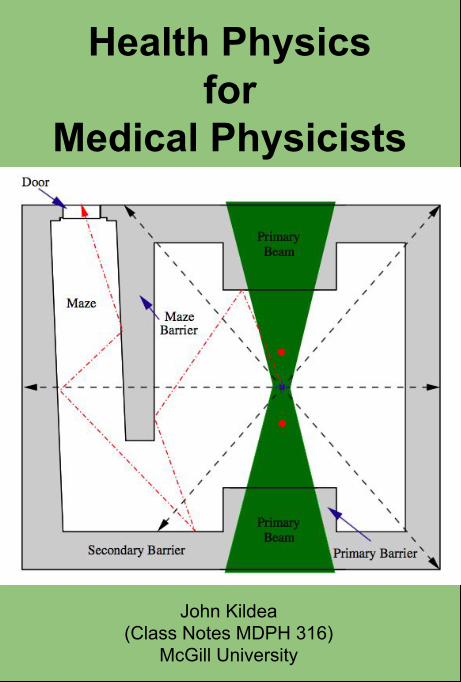
Health Physics for
Medical Physicists
John Kildea(Class Notes MDPH 316)
McGill University
Health Physics Notes - MDPH 613
Student Notes
John Kildea, PhD
Medical Physics Unit
McGill University
Montreal,Quebec
Fall 2015 Semester
Not for distribution beyond members of the Health Physics class.
c� John Kildea 2015
TABLE OF CONTENTS
LIST OF FIGURES . . . . . . . . . . . . . . . . . . . . . . . . . . . . v
LIST OF TABLES . . . . . . . . . . . . . . . . . . . . . . . . . . . . . x
1 Introduction . . . . . . . . . . . . . . . . . . . . . . . . . . . . . . 1
1.1 Overview of Course . . . . . . . . . . . . . . . . . . . . . . 11.2 Radiation and Radiation Protection . . . . . . . . . . . . . 11.3 Health Physics . . . . . . . . . . . . . . . . . . . . . . . . . 2
1.3.1 Public and Private Health . . . . . . . . . . . . . . 21.3.2 Health Physics and Medical Physics . . . . . . . . . 21.3.3 Health Physicists . . . . . . . . . . . . . . . . . . . 3
2 Radiation, its Origins and Interactions . . . . . . . . . . . . . . . 5
2.1 Definition of Radiation . . . . . . . . . . . . . . . . . . . . 52.2 The Inverse Square Law . . . . . . . . . . . . . . . . . . . 62.3 Ionization and Ionizing Radiation . . . . . . . . . . . . . . 8
2.3.1 The Bohr-Rutherford Atomic Model . . . . . . . . . 82.3.2 Ionization . . . . . . . . . . . . . . . . . . . . . . . 82.3.3 Ionizing Radiation . . . . . . . . . . . . . . . . . . . 8
2.4 Classification of Ionizing Radiation . . . . . . . . . . . . . 92.4.1 Radiation by Place of Origin . . . . . . . . . . . . . 10
Nuclear Radiation . . . . . . . . . . . . . . . . . . . . 10Non-nuclear Radiation . . . . . . . . . . . . . . . . . . 11
2.4.2 Indirectly Ionizing Radiation . . . . . . . . . . . . . 12Photons . . . . . . . . . . . . . . . . . . . . . . . . . . 12Neutrons . . . . . . . . . . . . . . . . . . . . . . . . . . 14
2.4.3 Directly Ionizing Radiation . . . . . . . . . . . . . . 162.4.4 Light Charged Particles . . . . . . . . . . . . . . . . 162.4.5 Intermediate Mass Charged Particles . . . . . . . . 172.4.6 Density of Ionization . . . . . . . . . . . . . . . . . 18
Radiation Penetrability . . . . . . . . . . . . . . . . . . 202.5 Background Radiation Exposure . . . . . . . . . . . . . . . 20
2.5.1 Natural Background Radiation . . . . . . . . . . . . 21Cosmic Radiation . . . . . . . . . . . . . . . . . . . . . 22Cosmogenic Radioactivity . . . . . . . . . . . . . . . . 22Primordial Radioactivity . . . . . . . . . . . . . . . . . 23Enhanced Natural Background Radiation . . . . . . . . 26
i
2.5.2 Artificial Background Radiation . . . . . . . . . . . 26Anthropogenic Background Radiation . . . . . . . . . . 26Medical Background Radiation . . . . . . . . . . . . . 26
2.6 The Physics of Radiation Protection . . . . . . . . . . . . . 272.6.1 Distance, Time and Shielding . . . . . . . . . . . . . 272.6.2 Scatter Radiation . . . . . . . . . . . . . . . . . . . 272.6.3 Bremsstrahlung . . . . . . . . . . . . . . . . . . . . 28
3 Quantification and Detection of Radiation . . . . . . . . . . . . . 29
3.1 Radiation Quantification . . . . . . . . . . . . . . . . . . . 293.1.1 Physical Quantities . . . . . . . . . . . . . . . . . . 30
Fluence and Flux . . . . . . . . . . . . . . . . . . . . . 30Exposure . . . . . . . . . . . . . . . . . . . . . . . . . 32Kerma . . . . . . . . . . . . . . . . . . . . . . . . . . . 33The Linear Attenuation Coe�cient . . . . . . . . . . . 35Half Value Layer and Tenth Value Layer . . . . . . . . 36Linear Energy Transfer . . . . . . . . . . . . . . . . . . 37Stopping Power . . . . . . . . . . . . . . . . . . . . . . 38Activity . . . . . . . . . . . . . . . . . . . . . . . . . . 39The Law of Radioactive Decay . . . . . . . . . . . . . . 39Half-Life . . . . . . . . . . . . . . . . . . . . . . . . . . 41Specific Activity . . . . . . . . . . . . . . . . . . . . . 42Carrier-Free Specific Activity . . . . . . . . . . . . . . 42Exposure Rate Constant . . . . . . . . . . . . . . . . . 43Air Kerma Rate Constant . . . . . . . . . . . . . . . . 43
3.1.2 Dosimetric Quantities . . . . . . . . . . . . . . . . . 44Absorbed Dose . . . . . . . . . . . . . . . . . . . . . . 46Equivalent Dose . . . . . . . . . . . . . . . . . . . . . . 47E↵ective Dose . . . . . . . . . . . . . . . . . . . . . . . 48Collective Equivalent Dose and Collective E↵ective Dose 48Operational Quantities for Area and Individual Moni-toring . . . . . . . . . . . . . . . . . . . . . . . . . . 49
3.1.3 Biological Quantities . . . . . . . . . . . . . . . . . 52Biological and E↵ective Half Life . . . . . . . . . . . . 52Committed Dose . . . . . . . . . . . . . . . . . . . . . 53The Annual Limit of Intake . . . . . . . . . . . . . . . 54Relative Biological E↵ectiveness . . . . . . . . . . . . . 54
3.1.4 Legal/Regulatory Quantities . . . . . . . . . . . . . 54Exemption Quantity . . . . . . . . . . . . . . . . . . . 55Transport Index . . . . . . . . . . . . . . . . . . . . . . 55
3.2 Radiation Detectors and Dosimeters . . . . . . . . . . . . . 553.2.1 Gas-Filled Detectors . . . . . . . . . . . . . . . . . . 56
Ionization Chambers . . . . . . . . . . . . . . . . . . . 58Proportional Counters and Neutron Detectors . . . . . 58
ii
Geiger-Muller Detectors . . . . . . . . . . . . . . . . . 593.2.2 Themoluminescent Dosimeters . . . . . . . . . . . . 603.2.3 Scintillation Detectors . . . . . . . . . . . . . . . . . 623.2.4 Semiconductor Detectors . . . . . . . . . . . . . . . 633.2.5 Photographic Emulsion Detectors . . . . . . . . . . 643.2.6 Bubble Detectors . . . . . . . . . . . . . . . . . . . 653.2.7 Calibration of Radiation Detectors . . . . . . . . . . 663.2.8 Radiation Detection in Practice . . . . . . . . . . . 68
4 Biological E↵ects of Radiation . . . . . . . . . . . . . . . . . . . . 70
4.1 Sources of Information . . . . . . . . . . . . . . . . . . . . 704.2 The Human Organism . . . . . . . . . . . . . . . . . . . . 714.3 Sequence of Radiation Damage . . . . . . . . . . . . . . . . 744.4 Radiation Damage at the Cellular Level . . . . . . . . . . . 75
4.4.1 Direct and Indirect Action in Cell Damage by Radiation 754.4.2 DNA Strand Breaks . . . . . . . . . . . . . . . . . . 764.4.3 Fate of Irradiated Cells . . . . . . . . . . . . . . . . 77
4.5 Radiation Injury at the Macroscopic Level . . . . . . . . . 784.5.1 Deterministic E↵ects . . . . . . . . . . . . . . . . . 79
LD50 . . . . . . . . . . . . . . . . . . . . . . . . . . . . 79Acute Whole Body Radiation Sickness . . . . . . . . . 80
4.5.2 Stochastic E↵ects . . . . . . . . . . . . . . . . . . . 82The ALARA Principle . . . . . . . . . . . . . . . . . . 83Cancer . . . . . . . . . . . . . . . . . . . . . . . . . . . 83
4.5.3 E↵ects of In-utero Irradiation . . . . . . . . . . . . . 84
5 Radiation Protection Organisations . . . . . . . . . . . . . . . . . 86
5.1 Historical Perspective . . . . . . . . . . . . . . . . . . . . . 865.2 Modern Organizations for Radiation Protection . . . . . . 87
5.2.1 International . . . . . . . . . . . . . . . . . . . . . . 895.2.2 National/Provincial . . . . . . . . . . . . . . . . . . 895.2.3 Municipal/Institutional . . . . . . . . . . . . . . . . 90
6 Radiation Protection Regulations . . . . . . . . . . . . . . . . . . 916.0.1 The Nuclear Safety and Control Act . . . . . . . . . 916.0.2 CNSC Regulations of Interest . . . . . . . . . . . . 93
Radiation Protection Regulations . . . . . . . . . . . . 93Nuclear Substances and Radiation Devices Regulations 96Class I Nuclear Facilities Regulations . . . . . . . . . . 97Class II Nuclear Facilities and Prescribed EquipmentRegulations . . . . . . . . . . . . . . . . . . . . . . . 97
6.0.3 Radiation Emitting Devices . . . . . . . . . . . . . . 1006.0.4 Transport Regulations for Radioactive Material and
Devices . . . . . . . . . . . . . . . . . . . . . . . . 101
iii
CANUTEC . . . . . . . . . . . . . . . . . . . . . . . . 102
6.1 Quebec Regulations Pertaining to Radiation Safety inMedicine . . . . . . . . . . . . . . . . . . . . . . . . . . . 102
7 Radiation Protection In Practice . . . . . . . . . . . . . . . . . . 104
7.1 Context . . . . . . . . . . . . . . . . . . . . . . . . . . . . 1047.1.1 Type of Exposure Situation . . . . . . . . . . . . . . 1057.1.2 Category of Exposed Individuals . . . . . . . . . . . 106
Workers . . . . . . . . . . . . . . . . . . . . . . . . . . 106Members of the Public . . . . . . . . . . . . . . . . . . 106Patients . . . . . . . . . . . . . . . . . . . . . . . . . . 107
7.1.3 Regulatory Jurisdiction . . . . . . . . . . . . . . . . 1077.2 Applying the Three Main Principles of Radiation Protection 107
7.2.1 The Principle of Justification . . . . . . . . . . . . . 107Decision Making and Licensing . . . . . . . . . . . . . 110Cost-Benefit Analysis . . . . . . . . . . . . . . . . . . . 110
7.2.2 The Principle of Optimization . . . . . . . . . . . . 1117.2.3 The Principle of Application of Dose Limits . . . . . 113
7.3 Implementing a Radiation Protection Program . . . . . . . 114Management Structure . . . . . . . . . . . . . . . . . . 115Radiation Protection Committee . . . . . . . . . . . . 116Radiation Safety O�cer . . . . . . . . . . . . . . . . . 117Radiation Safety Manual . . . . . . . . . . . . . . . . . 118Components of a Radiation Safety Program . . . . . . 118
8 Radiation in Healthcare . . . . . . . . . . . . . . . . . . . . . . . 120
9 Radiation Shielding for Medical Linear Accelerators . . . . . . . . 121
9.1 Equivalent and E↵ective Doses . . . . . . . . . . . . . . . . 1219.2 Production of Therapeutic Radiation Beams . . . . . . . . 1229.3 Treatment Room Geometry and Sources of Radiation . . . 1239.4 Shielding Materials . . . . . . . . . . . . . . . . . . . . . . 1279.5 Overview of Shielding Calculations . . . . . . . . . . . . . 127
9.5.1 Determination of the Barrier Attenuation Factor B 1309.5.2 Determination of the Number of TVLs and Barrier
Thickness . . . . . . . . . . . . . . . . . . . . . . 1329.6 Primary Barrier Calculation . . . . . . . . . . . . . . . . . 1339.7 Secondary Barrier Calculation . . . . . . . . . . . . . . . . 133
Shielding Calculation for Leakage Radiation . . . . . . 134Shielding Calculation for Patient Scattered Radiation . 135The Two Source Rule . . . . . . . . . . . . . . . . . . . 135
9.8 Maze and Door Calculations . . . . . . . . . . . . . . . . . 1369.8.1 Door Design . . . . . . . . . . . . . . . . . . . . . . 136
9.9 Radiation Shielding Evaluation . . . . . . . . . . . . . . . 137
iv
LIST OF FIGURESFigure page
1.1 An overview of the subjects encompassed by health physics. . 3
1.2 A concept map of the Health Physics material covered in thiscourse. . . . . . . . . . . . . . . . . . . . . . . . . . . . . . . 4
2.1 The old and new ionizing radiation warning signs. . . . . . . . 6
2.2 Illustration of the physical basis for the inverse-square law.If point source of radiation is held at the center of the twoconcentric spheres ↵ and �, then the radiation particle fluencemeasured on the surface of � will be less than that measuredon the surface of ↵ due to the spreading out (dilution) in alldirections of the radiation as it “radiates” outwards from thesource. . . . . . . . . . . . . . . . . . . . . . . . . . . . . . . 7
2.3 Classification of radiation. Figure adapted from Podgorsak(2010). . . . . . . . . . . . . . . . . . . . . . . . . . . . . . . 10
2.4 Spectral lines of four alpha-emitting radionuclides. Note that,for some radionuclides, the daughter nucleus may be left inan excited state such that the alpha particle does not receivethe maximum energy available. The remaining energy istypically emitted almost immediately (<12�12 s) as a gammaray. Figure from wikipedia.org. . . . . . . . . . . . . . . . . 11
2.5 The nuclear decay scheme and electron energy spectrum of Cs-137. The continuous beta particle spectrum and the discreteline resulting from K-shell conversion-electron are clearlyseen. Figures from Martin (2006) . . . . . . . . . . . . . . . 12
2.6 Regions of relative photon interaction predominance as afunction of h⌫ and Z. Figure from Podgorsak (2010) . . . . 14
2.7 Collision types in the Coulomb interaction: (a) Hard collision,in which the impact parameter b is of the order of the atomicradius, (b) Soft collision, in which b � a, and (c) Radiationcollision, where b ⌧ a. . . . . . . . . . . . . . . . . . . . . . 17
v
2.8 Schematic of a cosmic ray air shower, showing the soft (elec-tromagnetic), hard (penetrating) and nucleonic components.Cosmic ray muons form a significant portion of the back-ground radiation at the Earth’s surface. . . . . . . . . . . . 18
2.9 Ionization density associated with di↵erent types of radiation.The background is an electron micrograph of a human cell.The white dots are a computer simulation of ionizationtracks. Figure from Hall and Giaccia (2006). . . . . . . . . . 19
2.10 Illustration of the penetrability of various radiation beams.Figure from Baylor College of Medicine website. . . . . . . . 20
2.11 Breakdown of the estimated annual background radiation fora member of the population of the United States. Note: thecorresponding e↵ective dose values for Canada are estimatedat approximately 20% lower. Data from NCRP Report 93(1987). . . . . . . . . . . . . . . . . . . . . . . . . . . . . . . 21
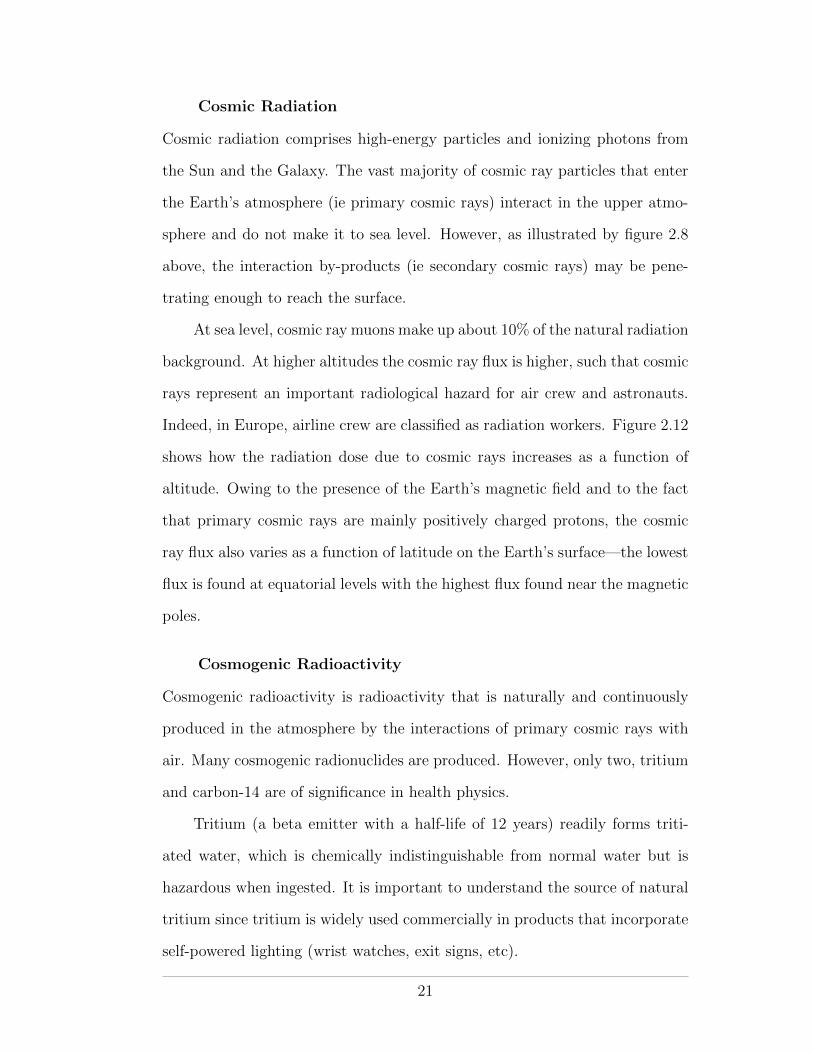
2.12 The increase in cosmic radiation exposure as a function ofaltitude above sea level. These data are for a latitude of 60�
north. Figure from Barish (2009). . . . . . . . . . . . . . . . 23
2.13 The four radioactive series. Figures from the HyperPhysicswebsite. . . . . . . . . . . . . . . . . . . . . . . . . . . . . . 25
3.1 The mass attenuation coe�cient for lead as a function of photonbeam energy. Photon beams with energy spectra in the pair-production regime may undergo beam softening. Figure fromPodgorsak (2010). . . . . . . . . . . . . . . . . . . . . . . . 38
3.2 Radioactive decay. The activity of a radioactive sample de-creases exponentially as a function of time. . . . . . . . . . . 41
3.3 The system of dosimetric units as laid out by the ICRP. . . . . 46
3.4 The system of operational dosimetric quantities as defined bythe ICRU and used in ICRP report 103 (ICRP Publication103, 2007). . . . . . . . . . . . . . . . . . . . . . . . . . . . 50
3.5 The ICRU sphere showing the dose delivery depths used inthe definitions of the ambient dose equivalent H⇤(d) (ICRPPublication 103, 2007). . . . . . . . . . . . . . . . . . . . . . 51
3.6 Basic leaky-capacitor circuit of a gas-filled detector. Typicalvoltage is about 250 V. . . . . . . . . . . . . . . . . . . . . . 57
vi
3.7 The voltage dependence of charge collection in a gas-filleddetector. Region A is known as the recombination region.Region B is the ionization chamber or saturation region.Region C is the proportional counter region. Region D isthe Geiger-Muller plateau and region E is the continuousdischarge region. . . . . . . . . . . . . . . . . . . . . . . . . 58
3.8 Energy-level diagram for a thermoluminescent material, show-ing electron and hole traps contained within the energy gapbetween the valence and conduction bands. (a) When irradi-ated, an electron may be excited from the valence band or ahole trap to the conduction band. Likewise, a hole may beexcited from the conduction band or from an electron trapto the valence band. (b) When heated su�ciently, a trappedelectron may gain enough energy to escape its trap. It maythen move within the conduction band until it encounters ahole trap where it will combine with a hole and emit a visualor UV photon. Likewise, a trapped hole may escape to thevalence band and move until it encounters an electron trap. 61
3.9 Schematic of a liquid scintillation detector with two PMTsoperating in coincidence mode. Figure from Cherry et al.(2003). . . . . . . . . . . . . . . . . . . . . . . . . . . . . . . 63
3.10 Cross-sectional view of a well-type scintillation detector. . . . 64
3.11 Simple overview of a semiconductor radiation detector. . . . . 65
3.12 Illustration of the shadow-cone technique, as carried out atthe MUHC. A survey meter is positioned at distance d froma radioactive source of known air kerma strength. (a) Thesurvey meter is exposed to direct primary radiation (dottedline) and scattered radiation (dashed line) from the source.(b) With a lead block in front of the source, the survey meteris exposed only to the scattered radiation. In both cases,the source travels distance x from the remote afterloaderunit to the measurement position through a catheter. Thetechnique facilitates measurement of the primary and scattercomponents of the radiation reaching the survey meter. . . . 67
4.1 The construction of organisms. . . . . . . . . . . . . . . . . . . 72
4.2 Overview of cell division by mitosis and meiosis. (a) In mitosisone parent cell duplicates and splits into two daughter cells.(b) In meiosis, one parent cell duplicates and then splits intofour daughter cells. . . . . . . . . . . . . . . . . . . . . . . . 73
vii
4.3 Overview of sequence of radiation damage. . . . . . . . . . . . 74
4.4 Overview of sequence of radiation damage. Figure from Halland Giaccia (2006). . . . . . . . . . . . . . . . . . . . . . . . 75
4.5 Illustration of the direct (top) and indirect (bottom) action ofradiation in damaging DNA. . . . . . . . . . . . . . . . . . . 76
4.6 The relationship between LET and RBE and an illustration ofthe reason for it. . . . . . . . . . . . . . . . . . . . . . . . . 77
4.7 The probability of the biological e↵ects of radiation againstdose. (a) Deterministic e↵ects have a threshold dose beyondwhich the probability of occurrence is 100% (b) Stochastice↵ects have no threshold. In the LNT model, the observedlinear dose-dependence at high doses is extrapolated back tothe origin. . . . . . . . . . . . . . . . . . . . . . . . . . . . . 80
6.1 The four placards used in the packaging and transport of Class7 radioactive materials. . . . . . . . . . . . . . . . . . . . . . 103
7.1 A process of optimization for radiation protection can beconsidered as a search for the level of protection S0 thatresults in the minimum of the sum of the radiation protectioncost X(S) and the cost of the detriment Y(S). S is thecollective e↵ective dose due to the residual radiation exposureto the population and is one quantity that may be used torepresent the level of protection. Figure based on the IAEAbasic safety standards IAEA (1982). . . . . . . . . . . . . . 112
7.2 Organigram showing the organization of communication andreporting for a generic hospital radiation safety program. . . 115
9.1 The main components of a linear accelerator used to producemegavoltage therapeutic photon and electron beams. . . . . 123
9.2 Schematics showing the geometry of a typical radiation therapytreatment room. (a) Front elevation view. (b) Plan view.The location of the isocenter is shown by a blue cross andthe source positions for beam directions perpendicular to theviewing angle are marked by red dots. . . . . . . . . . . . . 124
viii
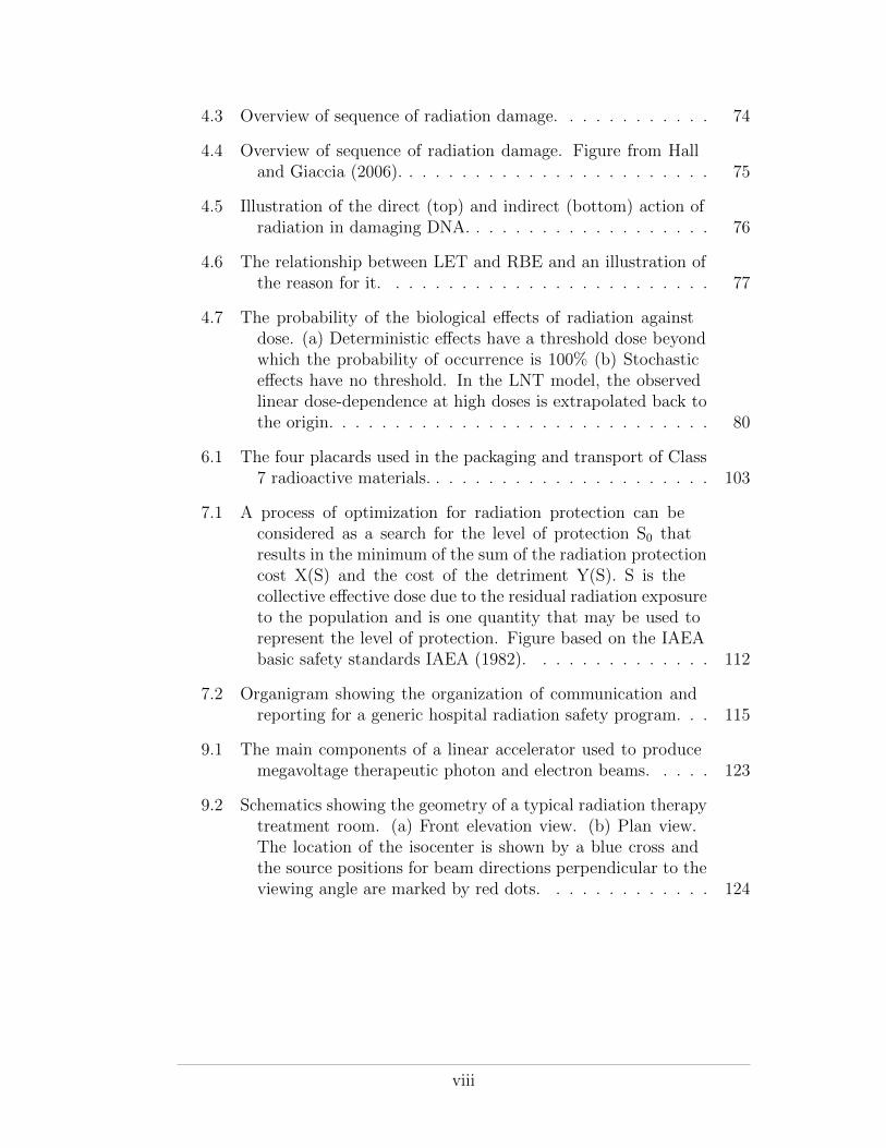
9.3 The primary (shaded green) and secondary (lines) radiationbeams produced inside a radiation therapy room and thebarriers used to provide shielding against them. Several sec-ondary beams are shown—the black dashed line representsleakage and scatter, the dot-dashed line represents photoneu-trons. As described in the text, all appear to emanate fromthe isocenter when all gantry angles are accounted for. Thelocation of the isocenter is shown by a blue cross and thesource locations for 180� gantry rotations are marked by reddots. . . . . . . . . . . . . . . . . . . . . . . . . . . . . . . . 126
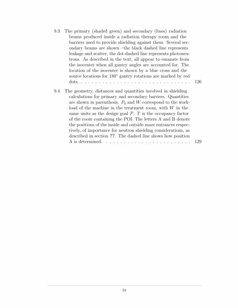
9.4 The geometry, distances and quantities involved in shieldingcalculations for primary and secondary barriers. Quantitiesare shown in parenthesis. P0 and W correspond to the work-load of the machine in the treatment room, with W in thesame units as the design goal P . T is the occupancy factorof the room containing the POI. The letters A and B denotethe positions of the inside and outside maze entrances respec-tively, of importance for neutron shielding considerations, asdescribed in section ??. The dashed line shows how positionA is determined. . . . . . . . . . . . . . . . . . . . . . . . . 129
ix
LIST OF TABLESTable page
1.1 Examples of the beneficial uses of radiation in modern society. 2
1.2 Examples of public health concerns in society. . . . . . . . . . . 2
2.1 The eight ways by which an atom may be ionized. . . . . . . . 9
2.2 The electromagnetic spectrum and photon applications in mod-ern society. Figure from Martin (2006) . . . . . . . . . . . . 13
2.3 LET values for various high and low LET radiation beams.Table from Podgorsak (2010). . . . . . . . . . . . . . . . . . 19
3.1 Physical quantities used to quantify radiation. . . . . . . . . . 31
3.2 Exposure rate constants for a number of radionuclides. Figurefrom Cember and Johnson (2009). . . . . . . . . . . . . . . 44
3.3 Dosimetric quantities and units used in radiation protection.These quantities apply equal to external and internal sourcesof exposure. . . . . . . . . . . . . . . . . . . . . . . . . . . . 45
3.4 Radiation weighting factors WR, as recommended by the ICRP. 47
3.5 Tissue weighting factors WT , as recommended by the ICRP. . . 49
3.6 The types of radiation detector most commonly used in fields ofmedical physics and health physics. . . . . . . . . . . . . . . 56
4.1 Deterministic and stochastic e↵ects of radiation damage. . . . . 79
4.2 The three whole-body radiation sickness syndromes. . . . . . . 80
5.1 A list of international and national organizations involved inradiation protection. . . . . . . . . . . . . . . . . . . . . . . 88
6.1 CNSC e↵ective and equivalent dose limits. ⇤ One-year dosimetryperiod is defined as beginning on January 1st and ending onDecember 31st. ⇤⇤ One calendar year is defined simply as aperiod of 12 months. . . . . . . . . . . . . . . . . . . . . . . 96
x
6.2 The nine classes of dangerous goods defined by the UN. Thedescriptions of each class and the appropriate placards areprovided on the Transport Canada website. . . . . . . . . . . 102
6.3 The signs used for the packaging of Class 7 radioactive materials,according to measured dose rate at the external surface andthe transport index. . . . . . . . . . . . . . . . . . . . . . . . 102
9.1 Summary of the properties of the shielding materials encoun-tered in NCRP 151. Primary barrier thicknesses equivalentto 2.5 m of ordinary concrete are provided. . . . . . . . . . . 128
9.2 NCRP 151 suggested occupancy factors. . . . . . . . . . . . . . 131
xi
CHAPTER 1Introduction
1.1 Overview of Course
Health physics is the area of public health that concerns itself with radiation
protection. In this course we will review the physics that governs the produc-
tion and interaction of ionizing radiation and the biolological consequences of
its interaction with living cells and tissue. We will then apply our knowledge
to the safe use of ionizing radiation, as codified in national regulations and
national and international memoranda. Although the concepts and principles
of radiation protection that we will cover in this course relate to the use of ion-
izing radiation generally, we will focus in particular on the safe use of ionizing
radiation in medicine.
1.2 Radiation and Radiation Protection
The use of ionizing radiation1 o↵ers great benefits to society. As detailed
in table 1.1, these benefits are realized in medicine, science/academia, indus-
try and power generation. However, radiation may be detrimental to human
health and its use necessarily involves management of risk so as to mitigate
injury to the individual user and to society in general. Radiation risk may
be controlled but not eliminated; any use of radiation entails an associated
non-zero risk. The goal of radiation protection is, thus, to minimize the risk
while maintaining the overall benefit to society.
1 From this point forward we will use the word radiation to mean ionizingradiation. This course does not deal with non-ionizing radiation.
1
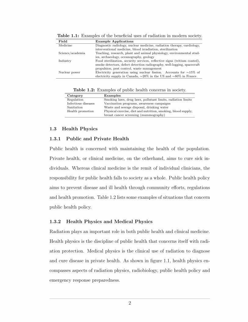
Table 1.1: Examples of the beneficial uses of radiation in modern society.Field Example ApplicationsMedicine Diagnostic radiology, nuclear medicine, radiation therapy, cardiology,
interventional medicine, blood irradiation, sterilizationScience/academia Teaching, research, plant and animal physiology, environmental stud-
ies, archaeology, oceanography, geologyIndustry Food sterilization, security services, reflective signs (tritium coated),
smoke detectors, defect detection radiography, well-logging, spacecraftpropulsion, pest control, waste management
Nuclear power Electricity generation using nuclear fission. Accounts for ⇠15% ofelectricity supply in Canada, ⇠20% in the US and ⇠80% in France
Table 1.2: Examples of public health concerns in society.Category ExamplesRegulation Smoking laws, drug laws, pollutant limits, radiation limitsInfectious diseases Vaccination programs, awareness campaignsSanitation Waste and sewage disposal, drinking waterHealth promotion Physical exercise, diet and nutrition, smoking, blood supply,
breast cancer screening (mammography)
1.3 Health Physics
1.3.1 Public and Private Health
Public health is concerned with maintaining the health of the population.
Private health, or clinical medicine, on the otherhand, aims to cure sick in-
dividuals. Whereas clinical medicine is the remit of individual clinicians, the
responsibility for public health falls to society as a whole. Public health policy
aims to prevent disease and ill health through community e↵orts, regulations
and health promotion. Table 1.2 lists some examples of situations that concern
public health policy.
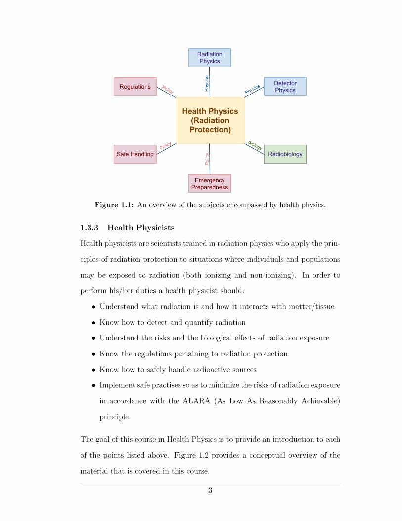
1.3.2 Health Physics and Medical Physics
Radiation plays an important role in both public health and clinical medicine.
Health physics is the discipline of public health that concerns itself with radi-
ation protection. Medical physics is the clinical use of radiation to diagnose
and cure disease in private health. As shown in figure 1.1, health physics en-
compasses aspects of radiation physics, radiobiology, public health policy and
emergency response preparedness.
2
Health Physics (Radiation Protection)
Regulations
Safe Handling
Emergency Preparedness
Radiation Physics
Detector Physics
Radiobiology
Phys
ics
Policy
Polic
y
Policy Physics
Biology
Figure 1.1: An overview of the subjects encompassed by health physics.
1.3.3 Health Physicists
Health physicists are scientists trained in radiation physics who apply the prin-
ciples of radiation protection to situations where individuals and populations
may be exposed to radiation (both ionizing and non-ionizing). In order to
perform his/her duties a health physicist should:
• Understand what radiation is and how it interacts with matter/tissue
• Know how to detect and quantify radiation
• Understand the risks and the biological e↵ects of radiation exposure
• Know the regulations pertaining to radiation protection
• Know how to safely handle radioactive sources
• Implement safe practises so as to minimize the risks of radiation exposure
in accordance with the ALARA (As Low As Reasonably Achievable)
principle
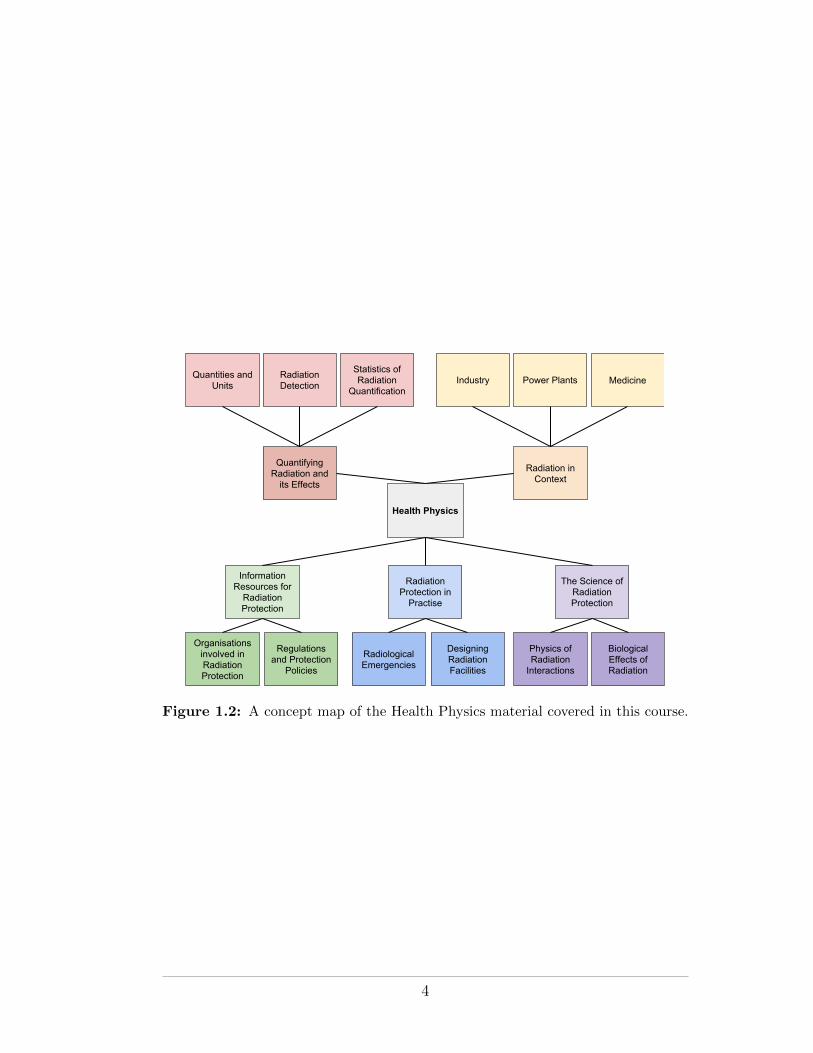
The goal of this course in Health Physics is to provide an introduction to each
of the points listed above. Figure 1.2 provides a conceptual overview of the
material that is covered in this course.
3
Health Physics
Organisations involved in Radiation Protection
Information Resources for
Radiation Protection
Regulations and Protection
Policies
Quantities and Units
Quantifying Radiation and
its Effects
Radiation Detection
Statistics of Radiation
Quantification
Radiation in Context
MedicineIndustry Power Plants
Radiological Emergencies
Radiation Protection in
Practise
Designing Radiation Facilities
The Science of Radiation Protection
Biological Effects of Radiation
Physics of Radiation
Interactions
Figure 1.2: A concept map of the Health Physics material covered in this course.
4
CHAPTER 2Radiation, its Origins and Interactions
The goal of this chapter is to review the physics of radiation and its interac-
tions. We will discuss what radiation is, how it is produced, how we classify
it and how it interacts with matter. We will also examine the sources of ra-
diation that society is exposed to. By the end of the chapter we should be
able to describe radiation to a member of the public and use our understand-
ing of radiation to explain the physics behind the three tenets of radiation
protection—distance, time and shielding.
2.1 Definition of Radiation
The term radiation has its origin in the Latin word radius, which was the name
for the spoke of a wheel. Radii (or rays) pointed outward from the center of
the wheel. Likewise, the term radius describes the distance from the center
of a circle to its circumference. Radiation, in the modern sense, describes a
stream of particles that emanate outward from a source. The particles may
be elementary or composite and can be charged or uncharged. However, all
radiating particles share the property that, as they move away from their
source, they carry kinetic energy that was imparted to them at the source.
The concept of radiation radiating out from a source was incorporated
into the original ionizing radiation warning sign. Known as the trefoil sign, it
was first used at the University of California Radiation Laboratory in Berkeley
in 1946. In 2007, the International Atomic Energy Agency (IAEA) drew up a
new ionizing radiation warning sign that incorporates the original but which
is supposed to better signify the danger of radiation (as opposed to resembling
5
(a) The original sign. (b) The new IAEA sign.
Figure 2.1: The old and new ionizing radiation warning signs.
a benign propeller!). The old and new ionizing radiation warning signs are
shown in figure 6.1.
2.2 The Inverse Square Law
The inverse-square law is a simple but important practical manifestation of the
definition of radiation. Using the definition of radiation as a stream of particles
carrying energy that emanate outwards from a source, we can understand the
inverse-square law.
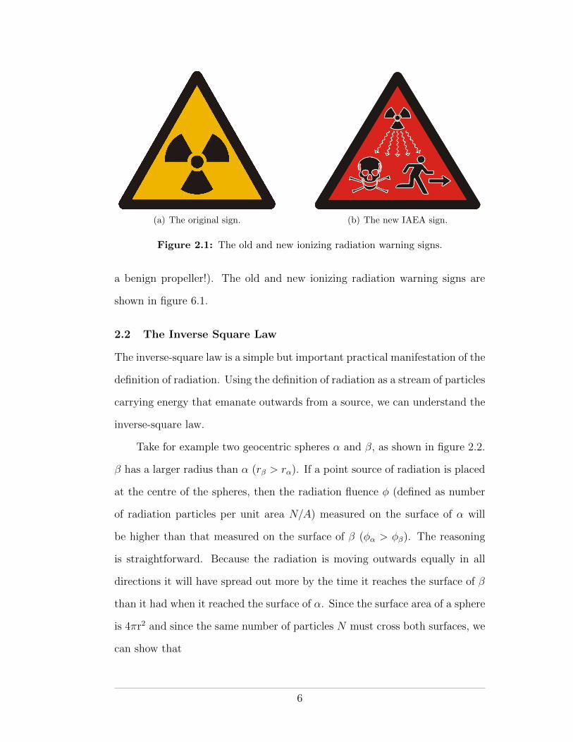
Take for example two geocentric spheres ↵ and �, as shown in figure 2.2.
� has a larger radius than ↵ (r� > r↵). If a point source of radiation is placed
at the centre of the spheres, then the radiation fluence � (defined as number
of radiation particles per unit area N/A) measured on the surface of ↵ will
be higher than that measured on the surface of � (�↵ > ��). The reasoning
is straightforward. Because the radiation is moving outwards equally in all
directions it will have spread out more by the time it reaches the surface of �
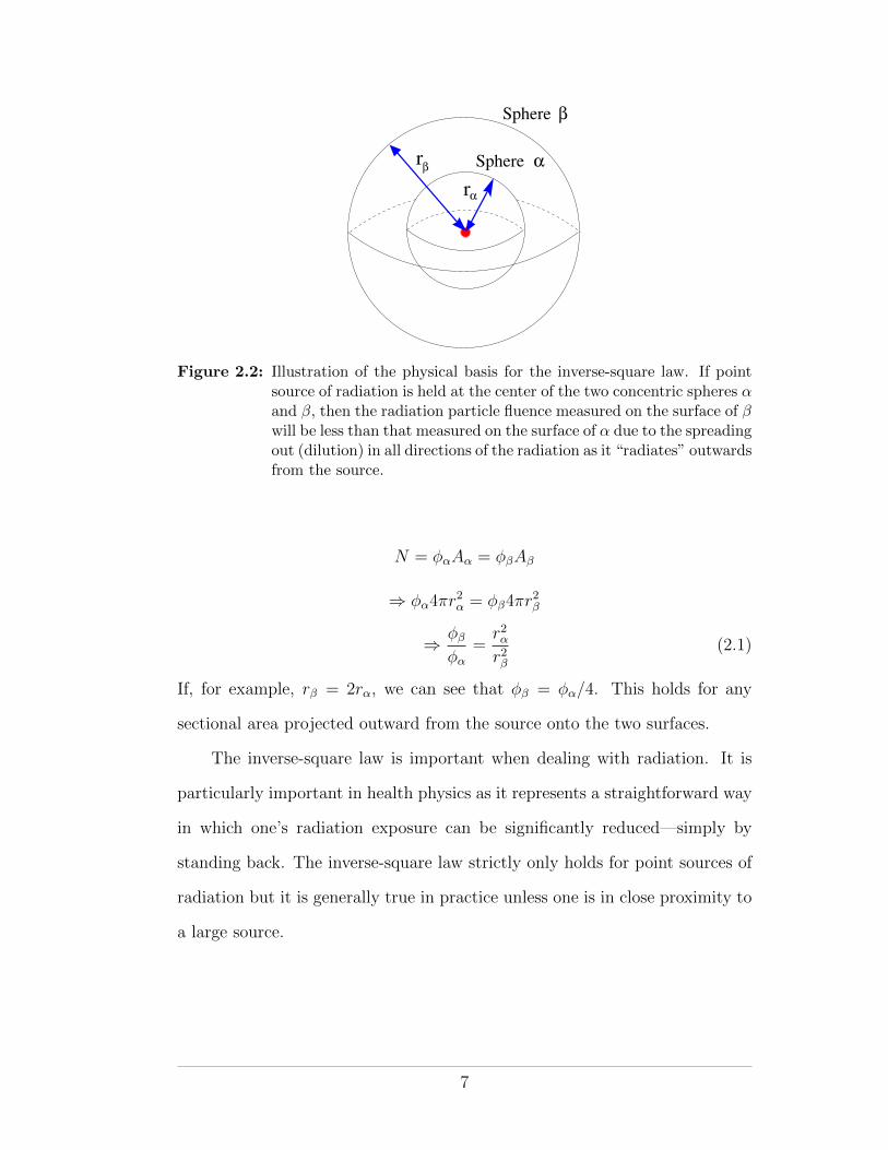
than it had when it reached the surface of ↵. Since the surface area of a sphere
is 4⇡r2 and since the same number of particles N must cross both surfaces, we
can show that
6
r
r
Sphere
Sphere
α
β
β
α
Figure 2.2: Illustration of the physical basis for the inverse-square law. If pointsource of radiation is held at the center of the two concentric spheres ↵and �, then the radiation particle fluence measured on the surface of �will be less than that measured on the surface of ↵ due to the spreadingout (dilution) in all directions of the radiation as it “radiates” outwardsfrom the source.
N = �↵A↵ = ��A�
) �↵4⇡r2↵ = ��4⇡r
2�
) ��
�↵
=r2↵r2�
(2.1)
If, for example, r� = 2r↵, we can see that �� = �↵/4. This holds for any
sectional area projected outward from the source onto the two surfaces.
The inverse-square law is important when dealing with radiation. It is
particularly important in health physics as it represents a straightforward way
in which one’s radiation exposure can be significantly reduced—simply by
standing back. The inverse-square law strictly only holds for point sources of
radiation but it is generally true in practice unless one is in close proximity to
a large source.
7
2.3 Ionization and Ionizing Radiation
2.3.1 The Bohr-Rutherford Atomic Model
An atom is the basic unit of matter. In the Rutherford-Bohr atomic model, an
atom comprises a central, dense, positively charged nucleus containing nucle-
ons (at least one positively charged proton and zero or more neutral neutrons)
surrounded by a cloud of negatively charged electrons that are bound to the
atom by the attractive positive charge of the nucleus. The electron cloud is
arranged into discrete shells, with electrons in the inner shells being more
tightly bound to the nucleus than those in the outer shells.
2.3.2 Ionization
Under normal circumstances, the positive charge of the nucleus and the neg-
ative charge of the electrons balance one another making the atom neutral.
However, if su�cient kinetic energy is given to a bound electron, it may over-
come the attractive electromagnetic force of the nucleus and escape the atom,
leaving behind a shell vacancy. The process of electron escape is known as
ionization and an ionized atom is called an ion. The energy required to eject
an electron from an atom is known as the electron’s binding energy. Electronic
binding energies are quantized according to atomic shell. The ionization po-
tential of an atom refers to the energy of its least bound electron, i.e., the
minimum energy needed to eject an electron from the atom. Ionization po-
tentials range from a few electron volts for the alkali elements to 24.6 eV for
helium.
2.3.3 Ionizing Radiation
Radiating neutral or charged particles with su�cient energy to eject electrons
from the matter they encounter are called ionizing radiation. The process of
8
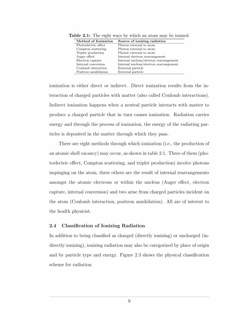
Table 2.1: The eight ways by which an atom may be ionized.Method of Ionization Source of ionizing radiationPhotoelectric e↵ect Photon external to atomCompton scattering Photon external to atomTriplet production Photon external to atomAuger e↵ect Internal electron rearrangementElectron capture Internal nucleus/electron rearrangementInternal conversion Internal nucleus/electron rearrangementCoulomb interaction External particlePositron annihilation External particle
ionization is either direct or indirect. Direct ionization results from the in-
teraction of charged particles with matter (also called Coulomb interactions).
Indirect ionization happens when a neutral particle interacts with matter to
produce a charged particle that in turn causes ionization. Radiation carries
energy and through the process of ionization, the energy of the radiating par-
ticles is deposited in the matter through which they pass.
There are eight methods through which ionization (i.e., the production of
an atomic shell vacancy) may occur, as shown in table 2.1. Three of them (pho-
toelectric e↵ect, Compton scattering, and triplet production) involve photons
impinging on the atom, three others are the result of internal rearrangements
amongst the atomic electrons or within the nucleus (Auger e↵ect, electron
capture, internal conversion) and two arise from charged particles incident on
the atom (Coulomb interaction, positron annihilation). All are of interest to
the health physicist.
2.4 Classification of Ionizing Radiation
In addition to being classified as charged (directly ionizing) or uncharged (in-
directly ionizing), ionizing radiation may also be categorized by place of origin
and by particle type and energy. Figure 2.3 shows the physical classification
scheme for radiation.
9
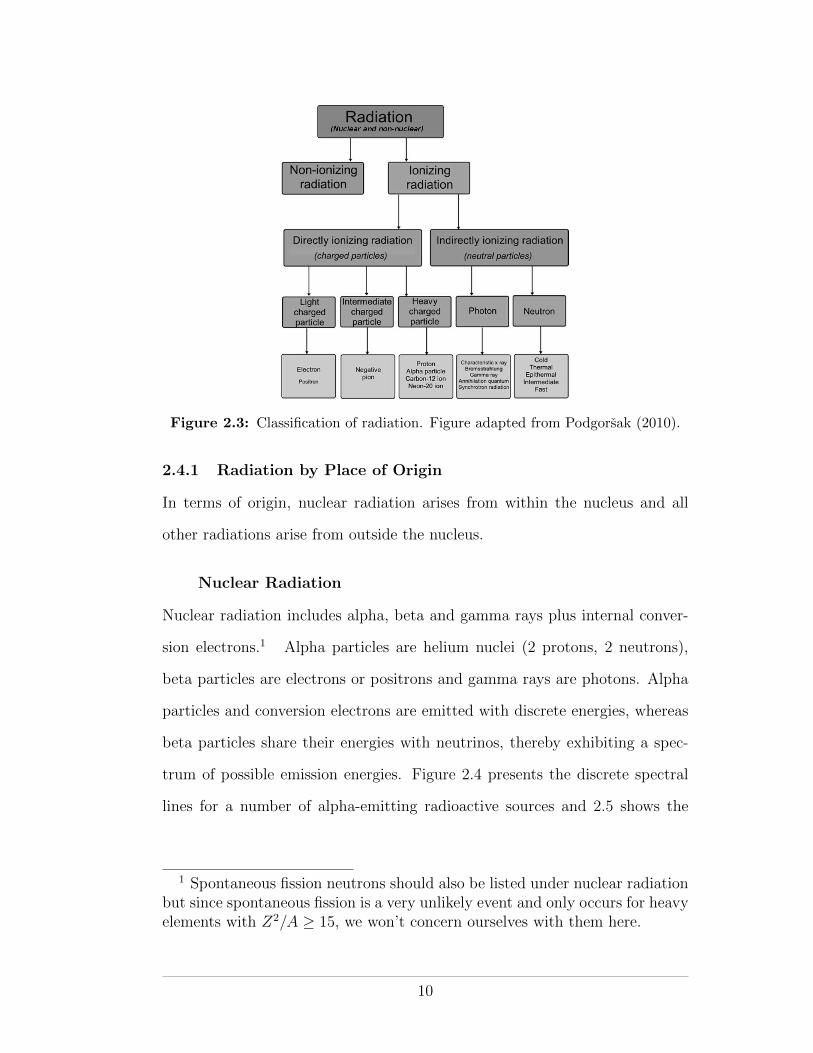
Figure 2.3: Classification of radiation. Figure adapted from Podgorsak (2010).
2.4.1 Radiation by Place of Origin
In terms of origin, nuclear radiation arises from within the nucleus and all
other radiations arise from outside the nucleus.
Nuclear Radiation
Nuclear radiation includes alpha, beta and gamma rays plus internal conver-
sion electrons.1 Alpha particles are helium nuclei (2 protons, 2 neutrons),
beta particles are electrons or positrons and gamma rays are photons. Alpha
particles and conversion electrons are emitted with discrete energies, whereas
beta particles share their energies with neutrinos, thereby exhibiting a spec-
trum of possible emission energies. Figure 2.4 presents the discrete spectral
lines for a number of alpha-emitting radioactive sources and 2.5 shows the
1 Spontaneous fission neutrons should also be listed under nuclear radiationbut since spontaneous fission is a very unlikely event and only occurs for heavyelements with Z2/A � 15, we won’t concern ourselves with them here.
10
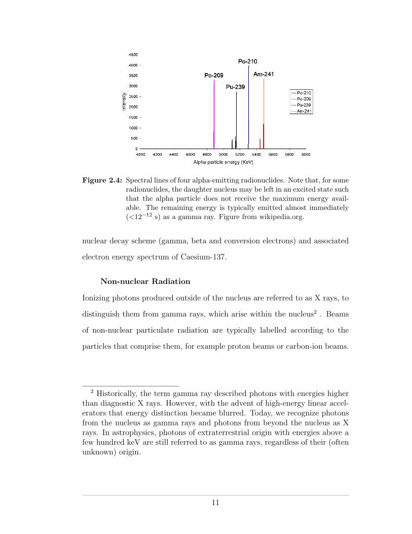
Figure 2.4: Spectral lines of four alpha-emitting radionuclides. Note that, for someradionuclides, the daughter nucleus may be left in an excited state suchthat the alpha particle does not receive the maximum energy avail-able. The remaining energy is typically emitted almost immediately(<12�12 s) as a gamma ray. Figure from wikipedia.org.
nuclear decay scheme (gamma, beta and conversion electrons) and associated
electron energy spectrum of Caesium-137.
Non-nuclear Radiation
Ionizing photons produced outside of the nucleus are referred to as X rays, to
distinguish them from gamma rays, which arise within the nucleus2 . Beams
of non-nuclear particulate radiation are typically labelled according to the
particles that comprise them, for example proton beams or carbon-ion beams.
2 Historically, the term gamma ray described photons with energies higherthan diagnostic X rays. However, with the advent of high-energy linear accel-erators that energy distinction became blurred. Today, we recognize photonsfrom the nucleus as gamma rays and photons from beyond the nucleus as Xrays. In astrophysics, photons of extraterrestrial origin with energies above afew hundred keV are still referred to as gamma rays, regardless of their (oftenunknown) origin.
11
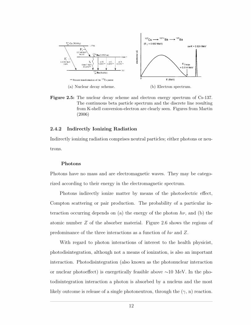
(a) Nuclear decay scheme. (b) Electron spectrum.
Figure 2.5: The nuclear decay scheme and electron energy spectrum of Cs-137.The continuous beta particle spectrum and the discrete line resultingfrom K-shell conversion-electron are clearly seen. Figures from Martin(2006)
2.4.2 Indirectly Ionizing Radiation
Indirectly ionizing radiation comprises neutral particles; either photons or neu-
trons.
Photons
Photons have no mass and are electromagnetic waves. They may be catego-
rized according to their energy in the electromagnetic spectrum.
Photons indirectly ionize matter by means of the photoelectric e↵ect,
Compton scattering or pair production. The probability of a particular in-
teraction occurring depends on (a) the energy of the photon h⌫, and (b) the
atomic number Z of the absorber material. Figure 2.6 shows the regions of
predominance of the three interactions as a function of h⌫ and Z.
With regard to photon interactions of interest to the health physicist,
photodisintegration, although not a means of ionization, is also an important
interaction. Photodisintegration (also known as the photonuclear interaction
or nuclear photoe↵ect) is energetically feasible above ⇠10 MeV. In the pho-
todisintegration interaction a photon is absorbed by a nucleus and the most
likely outcome is release of a single photoneutron, through the (�, n) reaction.
12
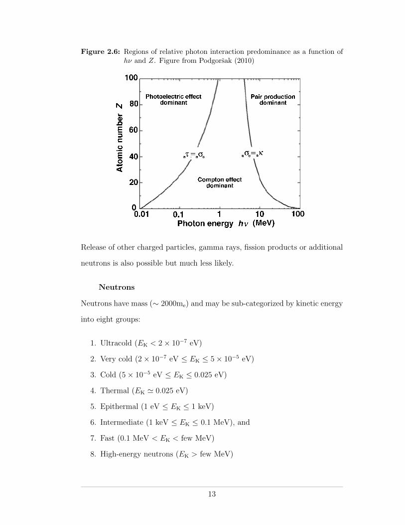
Figure 2.6: Regions of relative photon interaction predominance as a function ofh⌫ and Z. Figure from Podgorsak (2010)
Release of other charged particles, gamma rays, fission products or additional
neutrons is also possible but much less likely.
Neutrons
Neutrons have mass (⇠ 2000me) and may be sub-categorized by kinetic energy
into eight groups:
1. Ultracold (EK < 2⇥ 10�7 eV)
2. Very cold (2⇥ 10�7 eV EK 5⇥ 10�5 eV)
3. Cold (5⇥ 10�5 eV EK 0.025 eV)
4. Thermal (EK ' 0.025 eV)
5. Epithermal (1 eV EK 1 keV)
6. Intermediate (1 keV EK 0.1 MeV), and
7. Fast (0.1 MeV < EK < few MeV)
8. High-energy neutrons (EK > few MeV)
13
Neutrons are indirectly ionizing particles that interact through nuclear inter-
actions. Dose deposition by neutron beams is a two step process in which
(a) the neutrons produce charged particles by nuclear interactions and (b) the
charged particles deposit dose by Coulomb interactions.
Thermal, epithermal and fast neutrons have applications in medicine.
Thermal neutrons are used in boron-neutron capture therapy (BNCT) and
fast neutrons are used in external beam radiation therapy. Fast neutrons are
also used for in-vivo neutron activation analysis (for example, to quantify the
amount of calcium in the body for the diagnosis of osteopenia or osteoporosis)
and neutron radiography.
In industry, cold, thermal and hot neutrons are used in scattering and ra-
diography experiments to study the properties and the structure of materials.
Applications are found in the academic sciences (condensed matter physics,
biology, solid state chemistry, geology, mineralogy, etc) and in the nuclear,
aerospace and weapons industries. Neutrons are also produced and used in
nuclear power reactors.
High-energy neutrons have no direct application but are encountered in
the atmosphere, resulting from cosmic ray interactions, and at high-energy
particle accelerators.
There are five main processes through which neutrons may interact with
matter. They are elastic (neutron deflected without energy loss) and inelastic
(neutron deflected with change in energy) scattering, neutron capture, spalla-
tion and fission. The first three have important application in the moderation
(slowing down) and absorption of neutrons within the shielding of high-energy
radiation therapy installations. Neutron production and shielding in radiation
therapy will be discussed in detail later in this course.
14
2.4.3 Directly Ionizing Radiation
Numerous charged particles fall under the category of directly ionizing radia-
tion. In general three main groups are recognized, according to mass: light,
intermediate and heavy. Electrons/positrons are light charged particles. Pions
and muons are considered to have intermediate mass and all charged particles
with mass equal to or greater than the proton are considered heavy.
2.4.4 Light Charged Particles
Electrons and other charged particles interact through Coulomb interactions.
Coulomb interactions are either collisional or radiative. In collision interac-
tions (also known as ionization interactions), the charged particle energy is
lost to the absorbing medium, whereas in radiation interactions it is lost to
bremsstrahlung photons. Collision losses occur when the incident charged par-
ticle interacts with orbital electrons. Collisions can be hard (impact parameter
of the order of the atomic radius) or soft (impact parameter much greater than
the atomic radius). Hard collisions result in an ionized target atom, whereas
soft collisions cause atomic excitation. Radiation loss occurs when the inci-
dent charged particle is decelerated by the Coulomb field of the target nucleus.
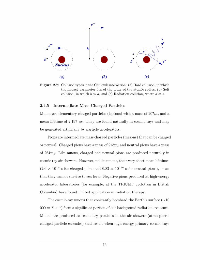
Hard, soft and radiation collisions are illustrated in Figure 2.7.
In medicine, electron beams are used in external beam radiation therapy
for the treatment of superficial lesions. In society, electron beams are most
frequently encountered in cathode ray tubes (CRTs), and until the advent of
solid-state electronics, in vacuum tubes. Although the electron beams gen-
erated by the CRTs of TVs and computer monitors are not in themselves a
radiation hazard, the bremsstrahlung beams (⇠40 kV) they produce may be.
Indeed, the US Food and Drug Administration regulates that the X-ray ra-
diation from TVs should not exceed 0.5 mR/hr. Modern TVs and computer
monitors employ liquid crystal displays and so are not a radiation hazard.
15
e−
e−
e−
e−
Nucleus
γ
b
b
b
(a) (b) (c)
Figure 2.7: Collision types in the Coulomb interaction: (a) Hard collision, in whichthe impact parameter b is of the order of the atomic radius, (b) Softcollision, in which b � a, and (c) Radiation collision, where b ⌧ a.
2.4.5 Intermediate Mass Charged Particles
Muons are elementary charged particles (leptons) with a mass of 207me and a
mean lifetime of 2.197 µs. They are found naturally in cosmic rays and may
be generated artificially by particle accelerators.
Pions are intermediate mass charged particles (mesons) that can be charged
or neutral. Charged pions have a mass of 273me and neutral pions have a mass
of 264me. Like muons, charged and neutral pions are produced naturally in
cosmic ray air showers. However, unlike muons, their very short mean lifetimes
(2.6 ⇥ 10�8 s for charged pions and 0.83 ⇥ 10�16 s for neutral pions), mean
that they cannot survive to sea level. Negative pions produced at high-energy
accelerator laboratories (for example, at the TRIUMF cyclotron in British
Columbia) have found limited application in radiation therapy.
The cosmic-ray muons that constantly bombard the Earth’s surface (⇠10
000 m�2 ·s�1) form a significant portion of our background radiation exposure.
Muons are produced as secondary particles in the air showers (atmospheric
charged particle cascades) that result when high-energy primary cosmic rays
16
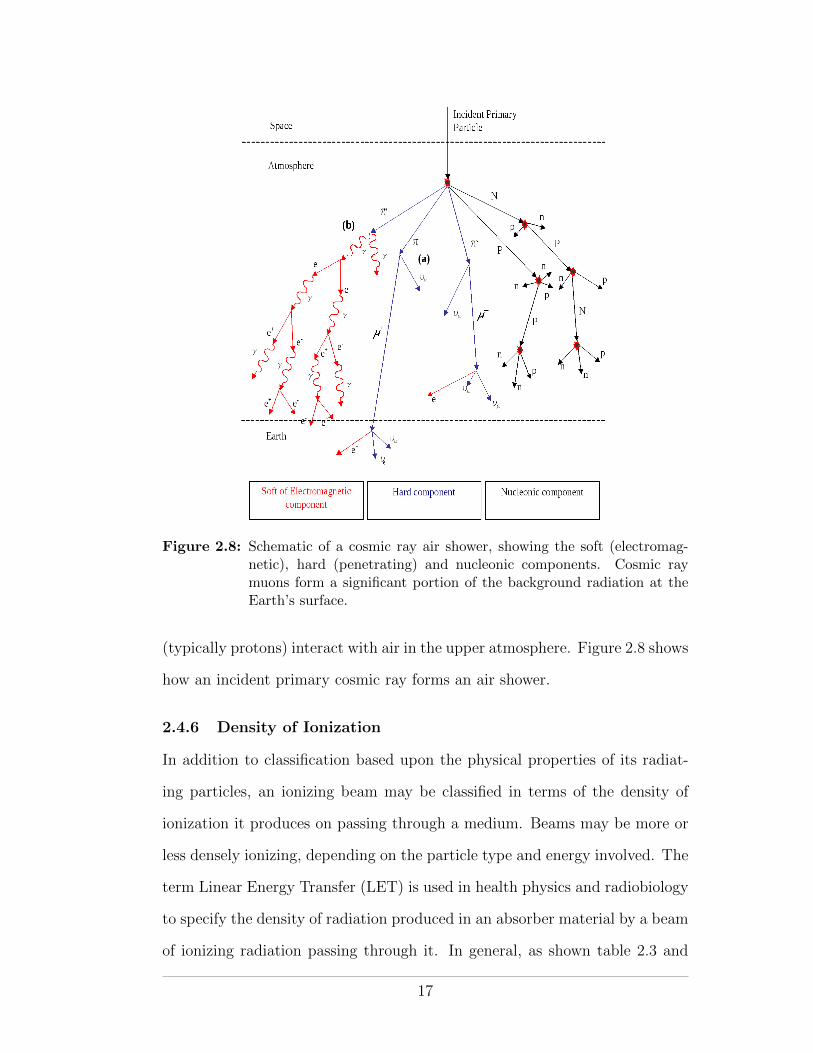
Figure 2.8: Schematic of a cosmic ray air shower, showing the soft (electromag-netic), hard (penetrating) and nucleonic components. Cosmic raymuons form a significant portion of the background radiation at theEarth’s surface.
(typically protons) interact with air in the upper atmosphere. Figure 2.8 shows
how an incident primary cosmic ray forms an air shower.
2.4.6 Density of Ionization
In addition to classification based upon the physical properties of its radiat-
ing particles, an ionizing beam may be classified in terms of the density of
ionization it produces on passing through a medium. Beams may be more or
less densely ionizing, depending on the particle type and energy involved. The
term Linear Energy Transfer (LET) is used in health physics and radiobiology
to specify the density of radiation produced in an absorber material by a beam
of ionizing radiation passing through it. In general, as shown table 2.3 and
17
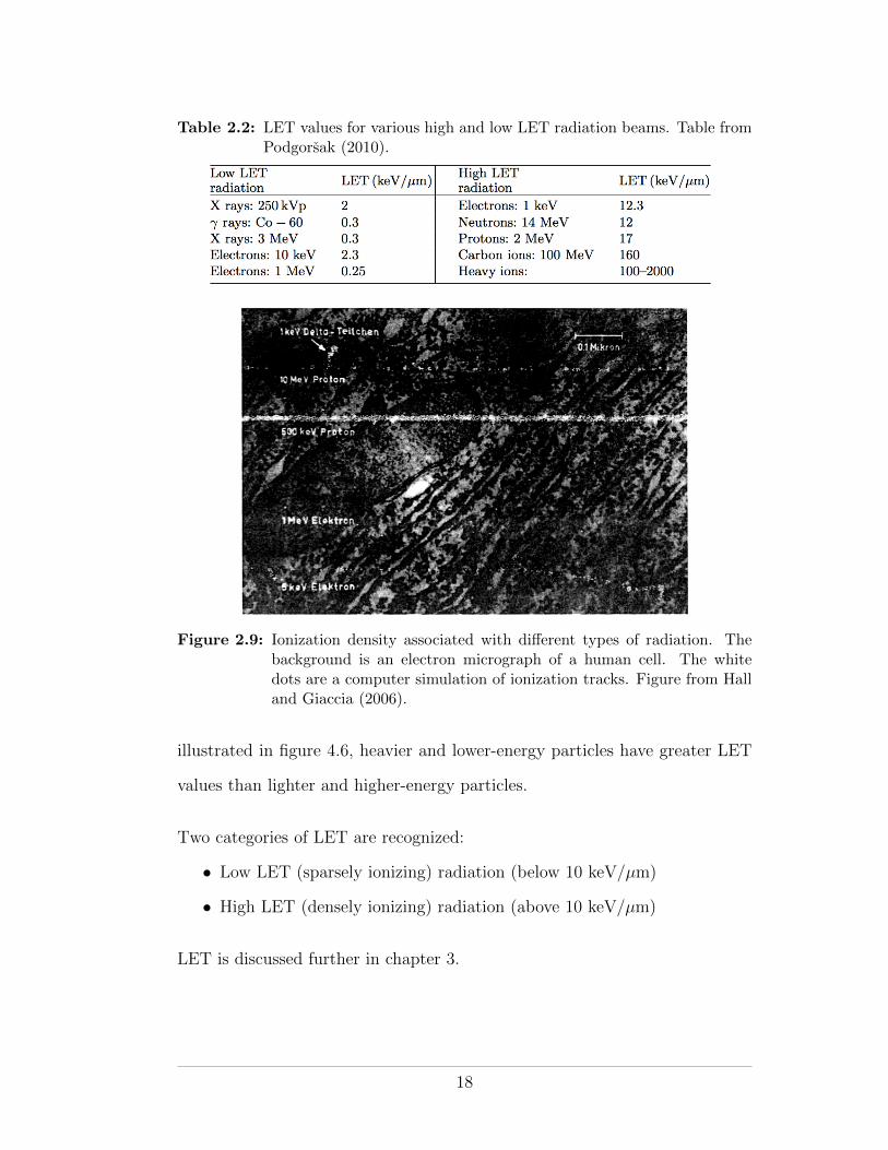
Table 2.2: LET values for various high and low LET radiation beams. Table fromPodgorsak (2010).
Figure 2.9: Ionization density associated with di↵erent types of radiation. Thebackground is an electron micrograph of a human cell. The whitedots are a computer simulation of ionization tracks. Figure from Halland Giaccia (2006).
illustrated in figure 4.6, heavier and lower-energy particles have greater LET
values than lighter and higher-energy particles.
Two categories of LET are recognized:
• Low LET (sparsely ionizing) radiation (below 10 keV/µm)
• High LET (densely ionizing) radiation (above 10 keV/µm)
LET is discussed further in chapter 3.
18
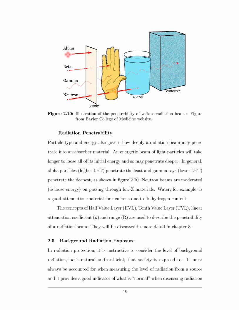
Figure 2.10: Illustration of the penetrability of various radiation beams. Figurefrom Baylor College of Medicine website.
Radiation Penetrability
Particle type and energy also govern how deeply a radiation beam may pene-
trate into an absorber material. An energetic beam of light particles will take
longer to loose all of its initial energy and so may penetrate deeper. In general,
alpha particles (higher LET) penetrate the least and gamma rays (lower LET)
penetrate the deepest, as shown in figure 2.10. Neutron beams are moderated
(ie loose energy) on passing through low-Z materials. Water, for example, is
a good attenuation material for neutrons due to its hydrogen content.
The concepts of Half Value Layer (HVL), Tenth Value Layer (TVL), linear
attenuation coe�cient (µ) and range (R) are used to describe the penetrability
of a radiation beam. They will be discussed in more detail in chapter 3.
2.5 Background Radiation Exposure
In radiation protection, it is instructive to consider the level of background
radiation, both natural and artificial, that society is exposed to. It must
always be accounted for when measuring the level of radiation from a source
and it provides a good indicator of what is “normal” when discussing radiation
19
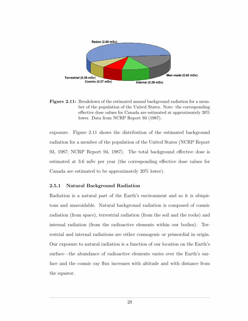
Figure 2.11: Breakdown of the estimated annual background radiation for a mem-ber of the population of the United States. Note: the correspondinge↵ective dose values for Canada are estimated at approximately 20%lower. Data from NCRP Report 93 (1987).
exposure. Figure 2.11 shows the distribution of the estimated background
radiation for a member of the population of the United States (NCRP Report
93, 1987; NCRP Report 94, 1987). The total background e↵ective dose is
estimated at 3.6 mSv per year (the corresponding e↵ective dose values for
Canada are estimated to be approximately 20% lower).
2.5.1 Natural Background Radiation
Radiation is a natural part of the Earth’s environment and so it is ubiqui-
tous and unavoidable. Natural background radiation is composed of cosmic
radiation (from space), terrestrial radiation (from the soil and the rocks) and
internal radiation (from the radioactive elements within our bodies). Ter-
restrial and internal radiations are either cosmogenic or primordial in origin.
Our exposure to natural radiation is a function of our location on the Earth’s
surface—the abundance of radioactive elements varies over the Earth’s sur-
face and the cosmic ray flux increases with altitude and with distance from
the equator.
20
Cosmic Radiation
Cosmic radiation comprises high-energy particles and ionizing photons from
the Sun and the Galaxy. The vast majority of cosmic ray particles that enter
the Earth’s atmosphere (ie primary cosmic rays) interact in the upper atmo-
sphere and do not make it to sea level. However, as illustrated by figure 2.8
above, the interaction by-products (ie secondary cosmic rays) may be pene-
trating enough to reach the surface.
At sea level, cosmic ray muons make up about 10% of the natural radiation
background. At higher altitudes the cosmic ray flux is higher, such that cosmic
rays represent an important radiological hazard for air crew and astronauts.
Indeed, in Europe, airline crew are classified as radiation workers. Figure 2.12
shows how the radiation dose due to cosmic rays increases as a function of
altitude. Owing to the presence of the Earth’s magnetic field and to the fact
that primary cosmic rays are mainly positively charged protons, the cosmic
ray flux also varies as a function of latitude on the Earth’s surface—the lowest
flux is found at equatorial levels with the highest flux found near the magnetic
poles.
Cosmogenic Radioactivity
Cosmogenic radioactivity is radioactivity that is naturally and continuously
produced in the atmosphere by the interactions of primary cosmic rays with
air. Many cosmogenic radionuclides are produced. However, only two, tritium
and carbon-14 are of significance in health physics.
Tritium (a beta emitter with a half-life of 12 years) readily forms triti-
ated water, which is chemically indistinguishable from normal water but is
hazardous when ingested. It is important to understand the source of natural
tritium since tritium is widely used commercially in products that incorporate
self-powered lighting (wrist watches, exit signs, etc).
21
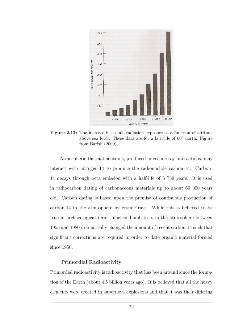
Figure 2.12: The increase in cosmic radiation exposure as a function of altitudeabove sea level. These data are for a latitude of 60� north. Figurefrom Barish (2009).
Atmospheric thermal neutrons, produced in cosmic ray interactions, may
interact with nitrogen-14 to produce the radionuclide carbon-14. Carbon-
14 decays through beta emission with a half-life of 5 730 years. It is used
in radiocarbon dating of carbonaceous materials up to about 60 000 years
old. Carbon dating is based upon the premise of continuous production of
carbon-14 in the atmosphere by cosmic rays. While this is believed to be
true in archaeological terms, nuclear bomb tests in the atmosphere between
1955 and 1980 dramatically changed the amount of recent carbon-14 such that
significant corrections are required in order to date organic material formed
since 1950.
Primordial Radioactivity
Primordial radioactivity is radioactivity that has been around since the forma-
tion of the Earth (about 4.5 billion years ago). It is believed that all the heavy
elements were created in supernova explosions and that it was their di↵ering
22
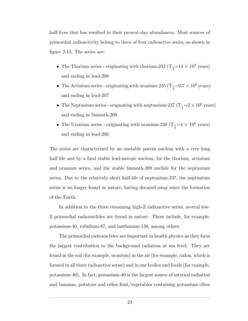
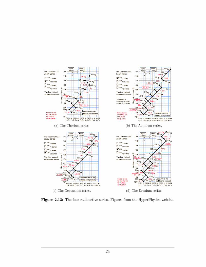
half-lives that has resulted in their present-day abundances. Most sources of
primordial radioactivity belong to three of four radioactive series, as shown in
figure 2.13. The series are:
• The Thorium series - originating with thorium-232 (T 12=14 ⇥ 109 years)
and ending in lead-208
• The Actinium series - originating with uranium-235 (T 12=0.7⇥ 109 years)
and ending in lead-207
• The Neptunium series - originating with neptunium-237 (T 12=2⇥ 106 years)
and ending in bismuth-209
• The Uranium series - originating with uranium-238 (T 12=4 ⇥ 109 years)
and ending in lead-206
The series are characterized by an unstable parent nucleus with a very long
half life and by a final stable lead-isotope nucleus, for the thorium, actinium
and uranium series, and the stable bismuth-209 nuclide for the neptunium
series. Due to the relatively short half-life of neptunium-237, the neptunium
series is no longer found in nature, having decayed away since the formation
of the Earth.
In addition to the three remaining high-Z radioactive series, several low-
Z primordial radionuclides are found in nature. These include, for example,
potassium-40, rubidium-87, and lanthanum-138, among others.
The primordial radionuclides are important in health physics as they form
the largest contribution to the background radiation at sea level. They are
found in the soil (for example, uranium) in the air (for example, radon, which is
formed in all three radioactive series) and in our bodies and foods (for example,
potassium-40). In fact, potassium-40 is the largest source of internal radiation
and bananas, potatoes and other fruit/vegetables containing potassium often
23
(a) The Thorium series. (b) The Actinium series.
(c) The Neptunium series. (d) The Uranium series.
Figure 2.13: The four radioactive series. Figures from the HyperPhysics website.
24
set o↵ security radiation detectors at ports and border crossings. As shown
in figure 2.11, radon alone is believed to account, on average, for half of the
background radiation (both natural and man-made) at sea-level.
Enhanced Natural Background Radiation
Enhanced sources of natural background radiation are sources that are natural
in origin but which result in increased levels of exposure due to human activity.
Examples include enhancement of cosmic radiation by flying at high-altitude
and enhancement of radon by living in insulated buildings where radon gas
levels may build up.
2.5.2 Artificial Background Radiation
In addition to natural background radiation, modern society is exposed to
radiation from artificial (man-made) sources. These include radiation exposure
for medical purposes, low-level radiation exposure from nuclear power plants
and radiation exposure from consumer goods (such as smoke detectors, wrist-
watches and CRT TV screens). Unlike natural background radiation, which
cannot be controlled, artificial background radiation levels can be controlled
and so are generally regulated by radiological or environmental authorities.
Anthropogenic Background Radiation
Artificial background radiation that does not include medical exposure (which
can be considered private exposure) is referred to as anthropogenic background
radiation. Many national and international bodies seek to understand, mea-
sure and reduce the levels of anthropogenic background radiation. These bod-
ies will be discussed in chapter 6.
Medical Background Radiation
Radiation exposure for medical purposes accounts for the vast majority of
modern society’s exposure to man-made radiation.
25
2.6 The Physics of Radiation Protection
2.6.1 Distance, Time and Shielding
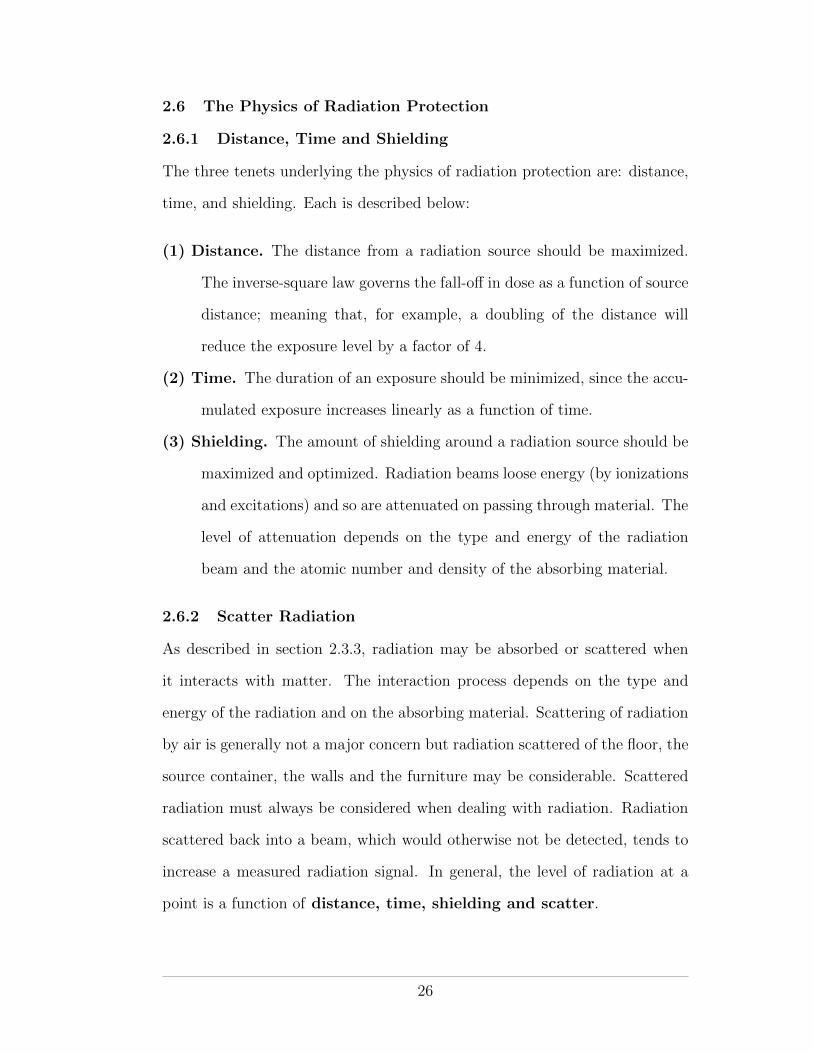
The three tenets underlying the physics of radiation protection are: distance,
time, and shielding. Each is described below:
(1) Distance. The distance from a radiation source should be maximized.
The inverse-square law governs the fall-o↵ in dose as a function of source
distance; meaning that, for example, a doubling of the distance will
reduce the exposure level by a factor of 4.
(2) Time. The duration of an exposure should be minimized, since the accu-
mulated exposure increases linearly as a function of time.
(3) Shielding. The amount of shielding around a radiation source should be
maximized and optimized. Radiation beams loose energy (by ionizations
and excitations) and so are attenuated on passing through material. The
level of attenuation depends on the type and energy of the radiation
beam and the atomic number and density of the absorbing material.
2.6.2 Scatter Radiation
As described in section 2.3.3, radiation may be absorbed or scattered when
it interacts with matter. The interaction process depends on the type and
energy of the radiation and on the absorbing material. Scattering of radiation
by air is generally not a major concern but radiation scattered of the floor, the
source container, the walls and the furniture may be considerable. Scattered
radiation must always be considered when dealing with radiation. Radiation
scattered back into a beam, which would otherwise not be detected, tends to
increase a measured radiation signal. In general, the level of radiation at a
point is a function of distance, time, shielding and scatter.
26
2.6.3 Bremsstrahlung
An energetic beam of radiating charged particles such as beta rays or electrons
may be completely stopped in an absorber material but may nevertheless
represent a radiation risk due to secondary bremsstrahlung radiation. For
example, the bremsstrahlung X rays produced by energetic beta particles are
generally much more penetrating than the beta particles that produced them.
Since bremsstrahlung beams are more e�ciently produced in high-Z materials,
beta-emitting radionuclides should be doubly-shielded, first by an inner layer
of low-Z material to absorb the beta particles, followed by an outer layer of
high-Z material to absorb the secondary X rays.
A similar double-shield is required to guard against gamma rays produced
by neutron capture events in the door of a high-energy radiation therapy room.
Neutron doors will be discussed later in the course.
27
CHAPTER 3Quantification and Detection of Radiation
In order to manage the exposure of individuals and society to radiation, ra-
diation levels must be measurable and their physical and biological e↵ects
quantifiable. Radiation dosimetry is the science of measuring and quantifying
radiation exposure in a way that allows for a meaningful dose-based assess-
ment of its biological e↵ects. Radiobiology is the science of understanding
those biological e↵ects.
In this chapter we will examine both the quantification and the detection
of radiation. By the end of the chapter we will be able to quantify radiation
both from a general physics point of view and from a radiation protection
perspective. We will be able to list the various types of radiation detector
available and, if presented with a particular radiation exposure scenario, de-
termine the most suitable radiation detector to use in order to quantify the
exposure.
3.1 Radiation Quantification
The “strength” of a particular radiation may quantified from a number of
di↵erent perspectives. Physicists and engineers working with radiation for
physical purposes (for example at a nuclear power plant or in a radiation
laboratory) are interested in purely physical quantities, such as the amount of
the radioactive substance or the rate at which it decays. Medical physicists
are generally interested in the radiation dose deposited in living tissue or in
a phantom. Health physicists are similarly interested in dose to tissue but
they are concerned not just with single tissues or individuals but rather with
28

multiple tissues, populations and perhaps multiple radiations and multiple
exposures. The choice of radiation quantity to use in any particular situation
depends on the type of radiation involved and the purpose of the measurement.
3.1.1 Physical Quantities
Physical quantities used in radiation physics allow for quantification of the
strength of a radiation source (or radiation field) without reference to biological
systems. As such, they are free of biological uncertainties and are generally
straightforward to measure. Table 3.1 lists the physical quantities of interest
in radiation physics. For convenience, a distinction is made between quantities
concerning radiation generally and quantities concerning radioactivity.
Fluence and Flux
Particle fluence � is defined as the number of particles (charged particles or
photons) crossing unit area
� =dN
dA
Particle flux, or fluence rate � is defined as the number of particles crossing
unit area per unit time.
� =d�
dt=
d
dt
✓dN
dA
◆
Particle fluence has units of m�2 and particle flux has units of m�2 · s�1
For a monoenergetic beam, the energy fluence is the product of the
particle fluence and the energy of the particles, and the energy flux (also
known as the intensity) is the energy fluence per unit time. The unit of energy
fluence is J ·m�2 and the unit of energy flux is J ·m�2 · s�1
For polyenergetic beams, the particle fluence and energy fluence spectra
are respectively defined as
29
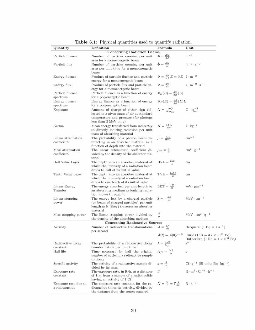
Table 3.1: Physical quantities used to quantify radiation.Quantity Definition Formula Unit
Concerning Radiation Beams
Particle fluence Number of particles crossing per unitarea for a monoenergetic beam
� = dNdA m�2
Particle flux Number of particles crossing per unitarea per unit time for a monoenergeticbeam
� = d�dt
m�2 · s�2
Energy fluence Product of particle fluence and particleenergy for a monoenergetic beam
= dN
dA
E = �E J ·m�2
Energy flux Product of particle flux and particle en-ergy for a monoenergetic beam
= d dt
J ·m�2 · s�1
Particle fluencespectrum
Particle fluence as a function of energyfor a polyenergetic beam
�E
(E) = d�dE
(E)
Energy fluencespectrum
Energy fluence as a function of energyfor a polyenergetic beam
E
(E) = d�dE
(E)E
Exposure Amount of charge of either sign col-lected in a given mass of air at standardtemperature and pressure (for photonsless than 3 MeV only)
X = �Q
�mairC · kg�1
air
Kerma Mean energy transferred from indirectlyto directly ionizing radiation per unitmass of absorbing material
K = dEtrdm J · kg�1
Linear attenuationcoe�cient
The probability of a photon beam in-teracting in an absorber material as afunction of depth into the material
µ = ln2HVL cm�1
Mass attenuationcoe�cient
The linear attenuation coe�cient di-vided by the density of the absorber ma-terial
µm
= µ
⇢
cm2 · g�1
Half Value Layer The depth into an absorber material atwhich the intensity of a radiation beamdrops to half of its initial value
HVL = ln2µ
cm
Tenth Value Layer The depth into an absorber material atwhich the intensity of a radiation beamdrops to one tenth of its initial value
TVL = ln10µ
cm
Linear EnergyTransfer
The energy absorbed per unit length byan absorbing medium as ionizing radia-tion moves through it
LET = dEdl keV · µm�1
Linear stoppingpower
The energy lost by a charged particle(or beam of charged particles) per unitlength as it (they) traverses an absorbermaterial
S = � dE
dx
MeV · cm�1
Mass stopping power The linear stopping power divided bythe density of the absorbing medium
S
⇢
MeV · cm2 · g�1
Concerning Radioactive Sources
Activity Number of radioactive transformationsper second
A = dNdt Becquerel (1 Bq = 1 s�1)
A(t) = A(0)e��t Curie (1 Ci = 3.7⇥ 1010 Bq)Rutherford (1 Rd = 1⇥ 106 Bq)
Radioactive decayconstant
The probability of a radioactive decaytransformation per unit time
� = ln2t1/2
s�1
Half life Time necessary for half the originalnumber of nuclei in a radioactive sampleto decay
t1/2 = ln2�
s
Specific activity The activity of a radioactive sample di-vided by its mass
a = Am
Ci · g�1 (SI unit: Bq · kg�1)
Exposure rateconstant
The exposure rate, in R/h, at a distanceof 1 m from a sample of a radionuclidehaving an activity of 1 Ci
� R ·m2 · Ci�1 · h�1
Exposure rate due toa radionuclide
The exposure rate constant for the ra-dionuclide times its activity, divided bythe distance from the source squared
X = X
t
= � Ad
2 R · h�1
30
Particle fluence spectrum = �E(E) =d�
dE(E)
Energy fluence spectrum = E(E) =d�
dE(E)E
Integration of the area under the particle fluence spectrum and under the en-
ergy fluence spectrum yields the total particle fluence and total energy fluence,
respectively, of a polyenergetic beam.
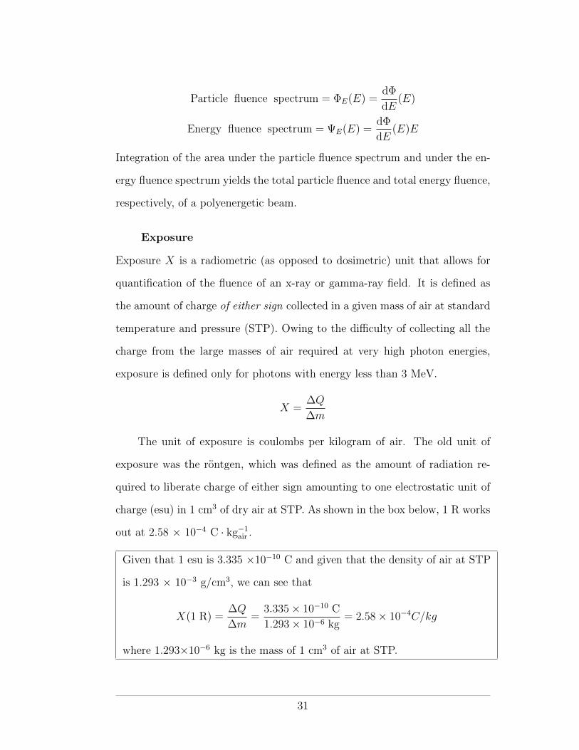
Exposure
Exposure X is a radiometric (as opposed to dosimetric) unit that allows for
quantification of the fluence of an x-ray or gamma-ray field. It is defined as
the amount of charge of either sign collected in a given mass of air at standard
temperature and pressure (STP). Owing to the di�culty of collecting all the
charge from the large masses of air required at very high photon energies,
exposure is defined only for photons with energy less than 3 MeV.
X =�Q
�m
The unit of exposure is coulombs per kilogram of air. The old unit of
exposure was the rontgen, which was defined as the amount of radiation re-
quired to liberate charge of either sign amounting to one electrostatic unit of
charge (esu) in 1 cm3 of dry air at STP. As shown in the box below, 1 R works
out at 2.58 ⇥ 10�4 C · kg�1air .
Given that 1 esu is 3.335 ⇥10�10 C and given that the density of air at STP
is 1.293 ⇥ 10�3 g/cm3, we can see that
X(1 R) =�Q
�m=
3.335⇥ 10�10 C
1.293⇥ 10�6 kg= 2.58⇥ 10�4C/kg
where 1.293⇥10�6 kg is the mass of 1 cm3 of air at STP.
31
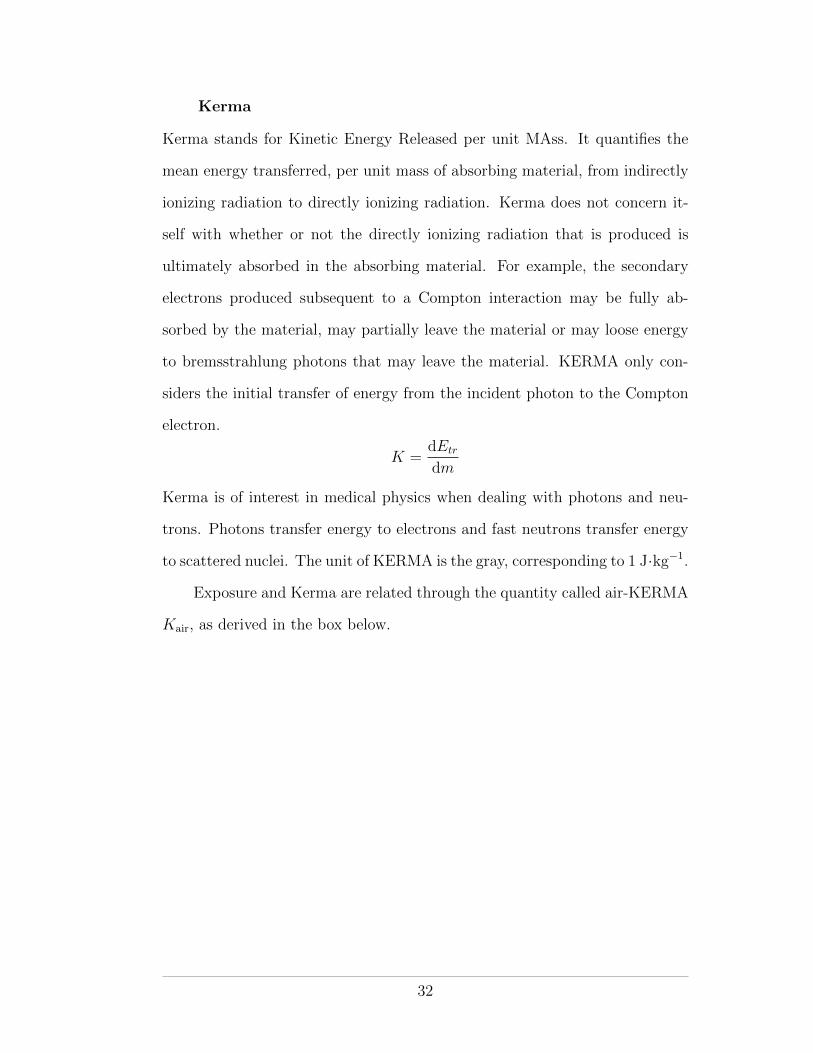
Kerma
Kerma stands for Kinetic Energy Released per unit MAss. It quantifies the
mean energy transferred, per unit mass of absorbing material, from indirectly
ionizing radiation to directly ionizing radiation. Kerma does not concern it-
self with whether or not the directly ionizing radiation that is produced is
ultimately absorbed in the absorbing material. For example, the secondary
electrons produced subsequent to a Compton interaction may be fully ab-
sorbed by the material, may partially leave the material or may loose energy
to bremsstrahlung photons that may leave the material. KERMA only con-
siders the initial transfer of energy from the incident photon to the Compton
electron.
K =dEtr
dm
Kerma is of interest in medical physics when dealing with photons and neu-
trons. Photons transfer energy to electrons and fast neutrons transfer energy
to scattered nuclei. The unit of KERMA is the gray, corresponding to 1 J·kg�1.
Exposure and Kerma are related through the quantity called air-KERMA
Kair, as derived in the box below.
32
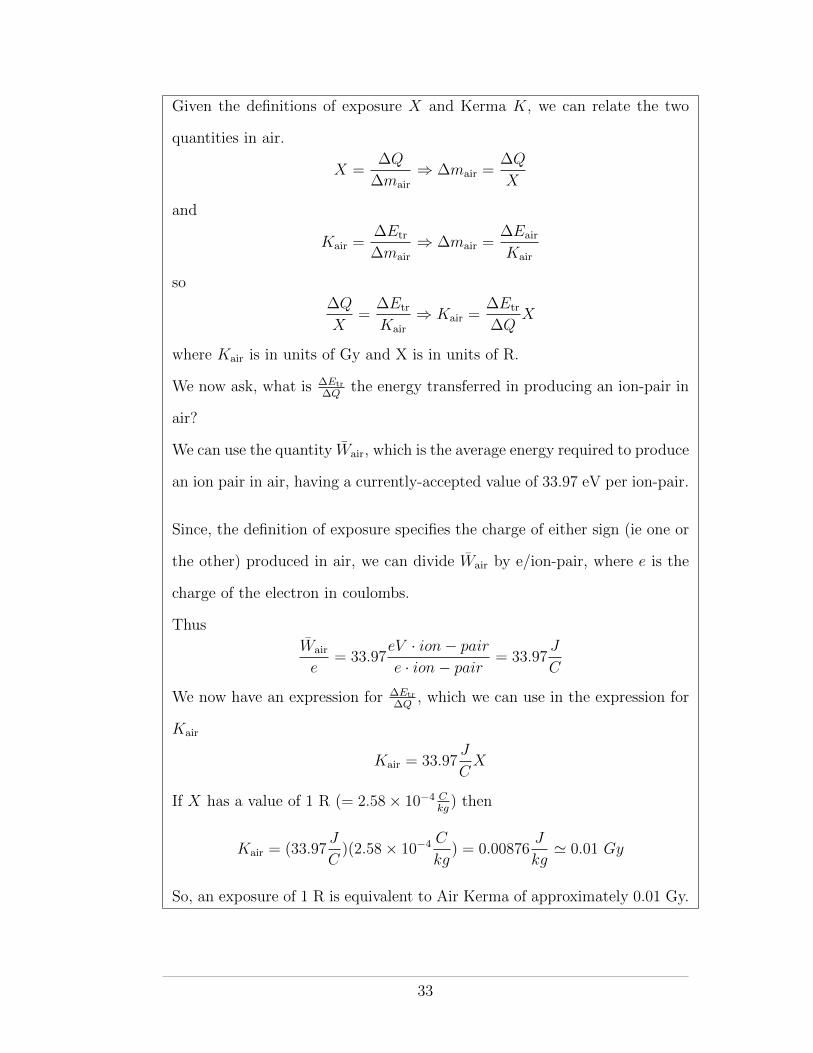
Given the definitions of exposure X and Kerma K, we can relate the two
quantities in air.
X =�Q
�mair) �mair =
�Q
X
and
Kair =�Etr
�mair) �mair =
�Eair
Kair
so�Q
X=�Etr
Kair) Kair =
�Etr
�QX
where Kair is in units of Gy and X is in units of R.
We now ask, what is �Etr�Q
the energy transferred in producing an ion-pair in
air?
We can use the quantity Wair, which is the average energy required to produce
an ion pair in air, having a currently-accepted value of 33.97 eV per ion-pair.
Since, the definition of exposure specifies the charge of either sign (ie one or
the other) produced in air, we can divide Wair by e/ion-pair, where e is the
charge of the electron in coulombs.
ThusWair
e= 33.97
eV · ion� pair
e · ion� pair= 33.97
J
C
We now have an expression for �Etr�Q
, which we can use in the expression for
Kair
Kair = 33.97J
CX
If X has a value of 1 R (= 2.58⇥ 10�4 Ckg) then
Kair = (33.97J
C)(2.58⇥ 10�4 C
kg) = 0.00876
J
kg' 0.01 Gy
So, an exposure of 1 R is equivalent to Air Kerma of approximately 0.01 Gy.
33
The Linear Attenuation Coe�cient
The linear attenuation coe�cient µ is described as the probability per unit
path length that a photon will have an interaction with the material through
which it is passing. It is synonymous with the radiation decay constant �
and may be derived in a similar manner (see below). The linear attenuation
coe�cient has units of cm�1. Its value depends on the energy of the photon
and on the density rho and atomic number Z of the absorbing material.
The Beer-Lambert law governs the exponential attenuation of a photon
beam as it passes through an absorbing material. In terms of µ, the Beer-
Lambert law may be expressed as
I(x) = I(0)e�µx, (3.1)
where I(x) is the intensity of the photon beam at depth x in the material and
I(0) is the incident intensity.
The linear attenuation coe�cient is normally determined using narrow-
beam geometry, in which the beam under study arises from a narrowly col-
limated source. Although narrow beams are seldom encountered in applied
radiation physics, they are practically useful, since they are more reproducible
than broad beams.
A linear attenuation coe�cient is defined for all photon interaction types,
with the overall coe�cient µ equalling the sum of the individual coe�cients:
µ = �R + ⌧ + �C + p + t + �PN (3.2)
where
• �R is the attenuation coe�cient for Rayleigh scattering
• ⌧ is the attenuation coe�cient for the photoelectric e↵ect
• �C is the attenuation coe�cient for Compton scattering
34
• p is the attenuation coe�cient for pair production
• t is the attenuation coe�cient for triplet production
• �PN is the attenuation coe�cient for photodisintegration
The mass attenuation coe�cient µm is equal to the linear attenuation
coe�cient divided by the mass per unit volume (ie density ⇢) of absorber ma-
terial. Since the mass attenuation coe�cient is independent of the density of
the absorber material it is a useful quantity when comparing the Z dependen-
cies of photon attenuation in various absorber materials. The SI unit for µm
is m2/kg, although the older unit of cm2/g is more often used in practice.
Half Value Layer and Tenth Value Layer
The Half Value Layer (HVL) is the depth into an absorber material at which
the intensity of a radiation beam drops to half of its initial intensity. It is
synonymous with the half-life of a radioactive material (see below). Likewise,
the Tenth Value Layer (TVL) is the depth at which the incident radiation
level is reduced to one tenth of its initial value. The relationship between the
HVL and the TVL is derived in the box below.
As is the case for half-life and the radioactive decay constant, the re-
lationship between HVL and TVL and the linear attenuation coe�cient is
straightforward to derive. The end results are
HV L =ln2
µ(3.3)
TV L =ln10
µ(3.4)
35
Since HV L = ln2µ
and TV L = ln10µ,
µ =ln2
HV L=
ln10
TV L
) HV L
TV L=
ln2
ln10
Both HVL and TVL are frequently encountered in health physics. They are
most often used in the context of shielding design.
Multiple HVLs (HVL1, HVL2, HVL3, etc) are defined. For a monoener-
getic beam, each HVL is of equal depth. For a polyenergetic beam, however,
beam hardening (or softening) will result in longer (or shorter) consecutive
HVLs. Similarly for TVL.
In beam hardening, lower energy photons are preferentially removed from
the beam as it is attenuated, leaving more penetrating higher-energy photons
behind. In beam softening, it is the higher energy photons that are removed.
Beam softening is seldom an issue in health physics but it may be encountered
when using very high-energy photon beams and high-Z materials, for which
pair-production may preferentially remove higher-energy photons. Figure 3.1
below shows how the mass attenuation coe�cient µ/⇢ for lead varies as a
function of photon energy. At low energies, µ/⇢ decreases with increasing
energy but at high energies (above about 2 MeV) it increases slowly as a
function of energy.
Linear Energy Transfer
Linear energy transfer (LET) is defined as the rate of energy absorption by an
absorbing medium as ionizing radiation moves through the medium.
LET =dE
dl
LET has units of keV/µm. It was discussed qualitatively in section ??.
36
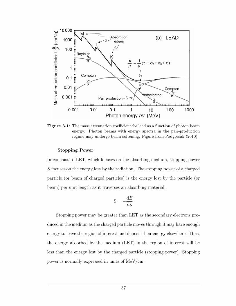
Figure 3.1: The mass attenuation coe�cient for lead as a function of photon beamenergy. Photon beams with energy spectra in the pair-productionregime may undergo beam softening. Figure from Podgorsak (2010).
Stopping Power
In contrast to LET, which focuses on the absorbing medium, stopping power
S focuses on the energy lost by the radiation. The stopping power of a charged
particle (or beam of charged particles) is the energy lost by the particle (or
beam) per unit length as it traverses an absorbing material.
S = �dE
dx
Stopping power may be greater than LET as the secondary electrons pro-
duced in the medium as the charged particle moves through it may have enough
energy to leave the region of interest and deposit their energy elsewhere. Thus,
the energy absorbed by the medium (LET) in the region of interest will be
less than the energy lost by the charged particle (stopping power). Stopping
power is normally expressed in units of MeV/cm.
37
The mass stopping power S⇢is equal to the (linear) stopping divided by
the density of the absorbing medium. The units of S⇢are MeV·cm2
g (ie MeV/cmg/cm3 ).
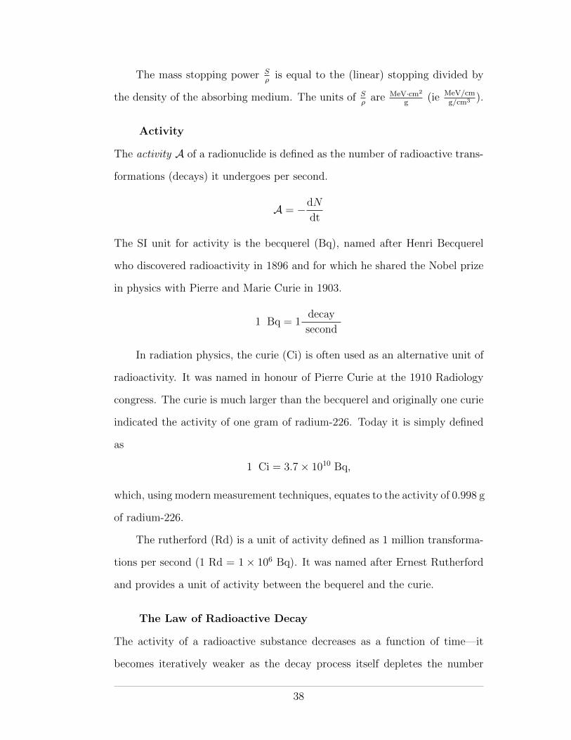
Activity
The activity A of a radionuclide is defined as the number of radioactive trans-
formations (decays) it undergoes per second.
A = �dN
dt
The SI unit for activity is the becquerel (Bq), named after Henri Becquerel
who discovered radioactivity in 1896 and for which he shared the Nobel prize
in physics with Pierre and Marie Curie in 1903.
1 Bq = 1decay
second
In radiation physics, the curie (Ci) is often used as an alternative unit of
radioactivity. It was named in honour of Pierre Curie at the 1910 Radiology
congress. The curie is much larger than the becquerel and originally one curie
indicated the activity of one gram of radium-226. Today it is simply defined
as
1 Ci = 3.7⇥ 1010 Bq,
which, using modern measurement techniques, equates to the activity of 0.998 g
of radium-226.
The rutherford (Rd) is a unit of activity defined as 1 million transforma-
tions per second (1 Rd = 1⇥ 106 Bq). It was named after Ernest Rutherford
and provides a unit of activity between the bequerel and the curie.
The Law of Radioactive Decay
The activity of a radioactive substance decreases as a function of time—it
becomes iteratively weaker as the decay process itself depletes the number
38
of unstable nuclei available for future decay. As such, one can state that
the (decreasing) rate of change in the number of nuclei (ie the activity) is
proportional to the number of nuclei present
A = �dN
dt/ N
) A = �dN
dt= �N
where A is the activity, �dN/dt is the rate of decrease in the number N of
radioactive nuclei at any time t and � is a constant of proportionality known as
the radioactive decay constant. Rearranging an integrating the above equation
we get Z N(t)
N0
dN
N= ��
Z t
0
dt,
which, when integrated gives
lnN(t)� lnN(0) = ��t
this may be further rearranged to give
lnN(t) = ��t+ lnN(0)
which, as shown in figure 3.2, is recognized as the equation of a straight line
with slope �� and intercept lnN(0).
Using the rules of logarithms, we can see that
ln
✓N(t)
N(0)
◆= ��t
which, using the definition of a logarithm, gives
N(t)
N(0)= e��t
39
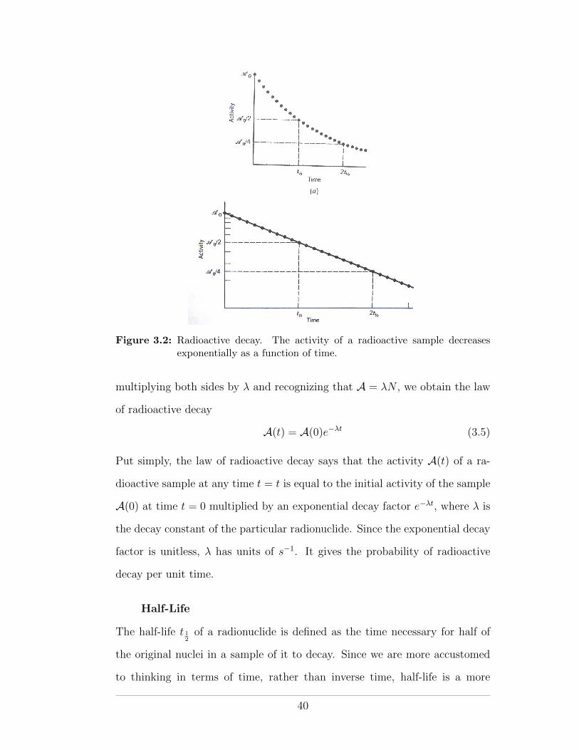
Figure 3.2: Radioactive decay. The activity of a radioactive sample decreasesexponentially as a function of time.
multiplying both sides by � and recognizing that A = �N , we obtain the law
of radioactive decay
A(t) = A(0)e��t (3.5)
Put simply, the law of radioactive decay says that the activity A(t) of a ra-
dioactive sample at any time t = t is equal to the initial activity of the sample
A(0) at time t = 0 multiplied by an exponential decay factor e��t, where � is
the decay constant of the particular radionuclide. Since the exponential decay
factor is unitless, � has units of s�1. It gives the probability of radioactive
decay per unit time.
Half-Life
The half-life t 12of a radionuclide is defined as the time necessary for half of
the original nuclei in a sample of it to decay. Since we are more accustomed
to thinking in terms of time, rather than inverse time, half-life is a more
40
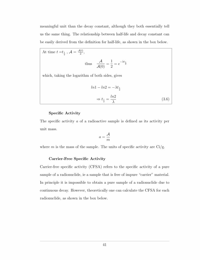
meaningful unit than the decay constant, although they both essentially tell
us the same thing. The relationship between half-life and decay constant can
be easily derived from the definition for half-life, as shown in the box below.
At time t =t 12, A = A(0)
2 ,
thusA
A(0)=
1
2= e
��t 12
which, taking the logarithm of both sides, gives
ln1� ln2 = ��t 12
) t 12=
ln2
�(3.6)
Specific Activity
The specific activity a of a radioactive sample is defined as its activity per
unit mass.
a =Am
where m is the mass of the sample. The units of specific activity are Ci/g.
Carrier-Free Specific Activity
Carrier-free specific activity (CFSA) refers to the specific activity of a pure
sample of a radionuclide, ie a sample that is free of impure “carrier” material.
In principle it is impossible to obtain a pure sample of a radionuclide due to
continuous decay. However, theoretically one can calculate the CFSA for each
radionuclide, as shown in the box below.
41
CFSA =Am
=�N
m
For one mole of pure radionuclide, we can say that N = NA and m = M,
where NA is Avogadro’s number and M is the atomic mass of the radionu-
clide.
) CFSA =�NA
M (3.7)
Exposure Rate Constant
The exposure rate constant � is defined as the exposure rate, in R/h, at a
distance of 1 m from a sample of a radionuclide having an activity of 1 Ci.
Its unit is R·m2
Ci·h . The exposure rate constant accounts for photons only but
includes all photons arising from decay of the nucleus, including gamma rays,
characteristic X rays (following electron capture) and bremsstrahlung photons
(following beta decay).
Each radionuclide has a unique value of � that may be calculated by
considering all of the photon producing decay modes, their energies and their
attenuations in air. Table 3.2 presents � values for some commonly used
radionuclides. Knowing � one can determine the expected exposure rate of a
source at a given distance from the source.
X =X
t= �
Ad2
Considering the definition of �, one can see that it incorporates the three tenets
of radiation protection, distance, time and shielding (by air in this case) and
the activity of a radioactive sample.
Air Kerma Rate Constant
The Air Kerma rate constant �AKR is defined as the Air Kerma rate, in Gy/h,
at a distance of 1 m from a sample of a radionuclide having an activity of
42

Table 3.2: Exposure rate constants for a number of radionuclides. Figure fromCember and Johnson (2009).
1 MBq. In Health Physics its unit is Sv·m2
MBq·h . It provides the same information
as the exposure rate constant but expressed in more modern units. Like the
exposure rate constant, it accounts for photons only but includes all photons
arising from decay of the nucleus, including gamma rays, characteristic X
rays (following electron capture) and bremsstrahlung photons (following beta
decay). Table 3.2 presents �AKR values for some commonly used radionuclides.
3.1.2 Dosimetric Quantities
In the early days of radiation usage, dosimetric quantities (quantities used to
quantify dose to tissue) were poorly defined. Two very simple quantities were
employed. The first was known as the paper-clip unit and it referred to the
amount of radiation required to produce a detectable shadow of a paper clip on
a piece of film. A radiation worker would carry a piece of film with a paper clip
while carrying out his duties and examine it at the end of each day to quantify
his exposure. For larger radiation doses, such as those used in therapy, the skin
erythema unit was defined. It was the amount of radiation needed to produce
skin redness. Nowadays we can recognize that neither quantity is really useful
as neither is biologically meaningful and both are energy dependent.
43
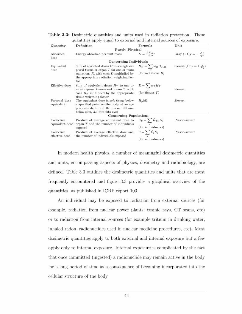
Table 3.3: Dosimetric quantities and units used in radiation protection. Thesequantities apply equal to external and internal sources of exposure.
Quantity Definition Formula UnitPurely Physical
Absorbeddose
Energy absorbed per unit mass D = �Eabs�m
Gray (1 Gy = 1 J
kg
)
Concerning Individuals
Equivalentdose
Sum of absorbed doses D to a single ex-posed tissue or organ T for one or moreradiations R, with each D multiplied bythe appropriate radiation weighting fac-tor
HT
=X
R
wR
DT,R
(for radiations R)
Sievert (1 Sv = 1 J
kg
)
E↵ective dose Sum of equivalent doses HT
to one ormore exposed tissues and organs T , witheach H
T
multiplied by the appropriatetissue weighting factor
E =X
T
wT
HT
(for tissues T )Sievert
Personal doseequivalent
The equivalent dose in soft tissue belowa specified point on the body at an ap-propriate depth d (0.07 mm or 10.0 mmbelow skin, 3.0 mm into eye)
Hp
(d) Sievert
Concerning Populations
Collectiveequivalent dose
Product of average equivalent dose toorgan T and the number of individualsexposed
ST
=X
i
HT,i
Ni
(for individuals i)
Person-sievert
Collectivee↵ective dose
Product of average e↵ective dose andthe number of individuals exposed
S =X
i
Ei
Ni
(for individuals i)
Person-sievert
In modern health physics, a number of meaningful dosimetric quantities
and units, encompassing aspects of physics, dosimetry and radiobiology, are
defined. Table 3.3 outlines the dosimetric quantities and units that are most
frequently encountered and figure 3.3 provides a graphical overview of the
quantities, as published in ICRP report 103.
An individual may be exposed to radiation from external sources (for
example, radiation from nuclear power plants, cosmic rays, CT scans, etc)
or to radiation from internal sources (for example tritium in drinking water,
inhaled radon, radionuclides used in nuclear medicine procedures, etc). Most
dosimetric quantities apply to both external and internal exposure but a few
apply only to internal exposure. Internal exposure is complicated by the fact
that once committed (ingested) a radionuclide may remain active in the body
for a long period of time as a consequence of becoming incorporated into the
cellular structure of the body.
44
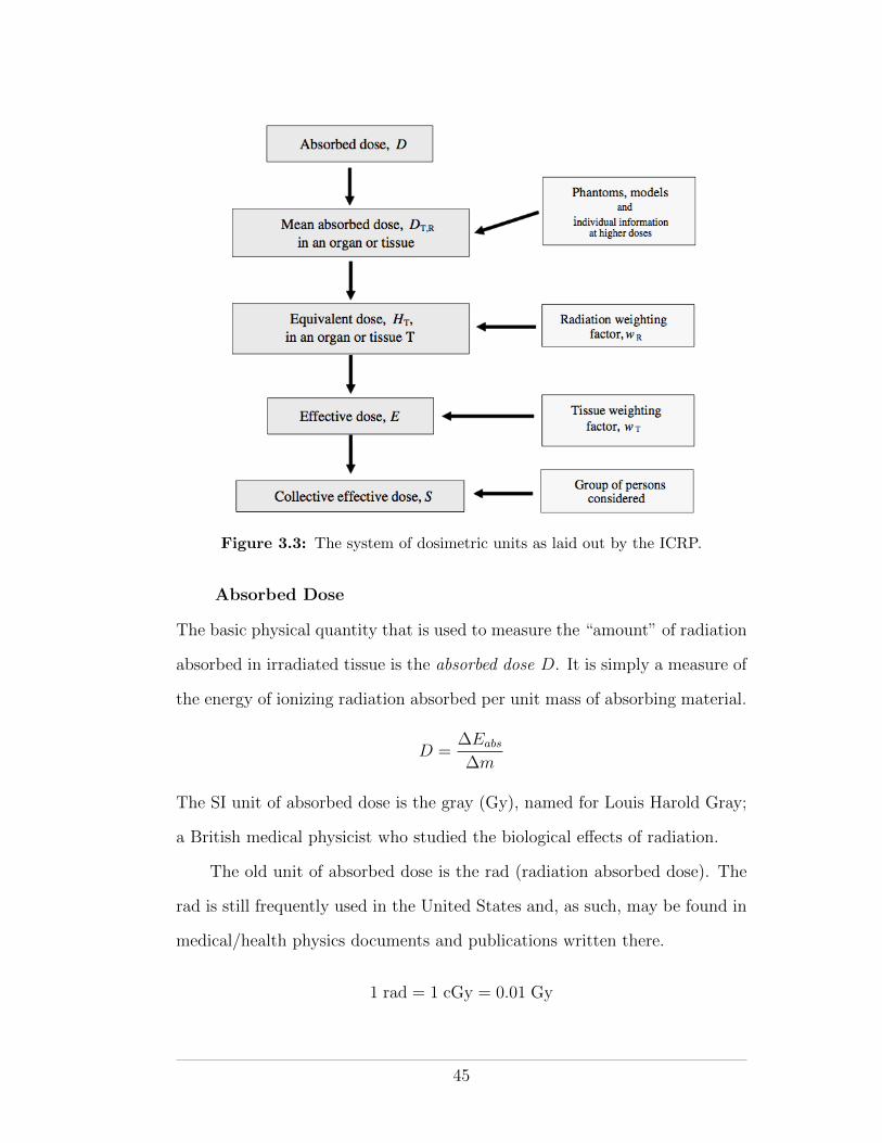
Figure 3.3: The system of dosimetric units as laid out by the ICRP.
Absorbed Dose
The basic physical quantity that is used to measure the “amount” of radiation
absorbed in irradiated tissue is the absorbed dose D. It is simply a measure of
the energy of ionizing radiation absorbed per unit mass of absorbing material.
D =�Eabs
�m
The SI unit of absorbed dose is the gray (Gy), named for Louis Harold Gray;
a British medical physicist who studied the biological e↵ects of radiation.
The old unit of absorbed dose is the rad (radiation absorbed dose). The
rad is still frequently used in the United States and, as such, may be found in
medical/health physics documents and publications written there.
1 rad = 1 cGy = 0.01 Gy
45
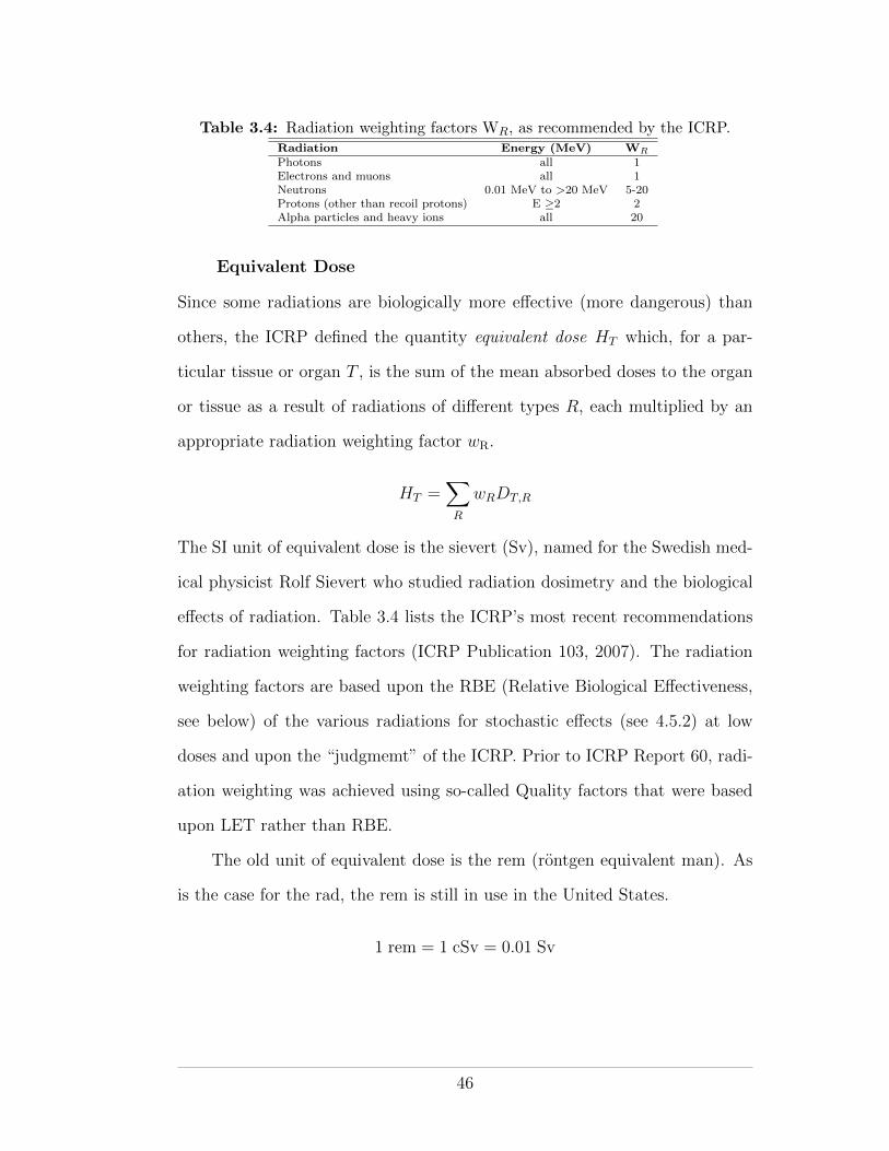
Table 3.4: Radiation weighting factors WR, as recommended by the ICRP.Radiation Energy (MeV) W
R
Photons all 1Electrons and muons all 1Neutrons 0.01 MeV to >20 MeV 5-20Protons (other than recoil protons) E �2 2Alpha particles and heavy ions all 20
Equivalent Dose
Since some radiations are biologically more e↵ective (more dangerous) than
others, the ICRP defined the quantity equivalent dose HT which, for a par-
ticular tissue or organ T , is the sum of the mean absorbed doses to the organ
or tissue as a result of radiations of di↵erent types R, each multiplied by an
appropriate radiation weighting factor wR.
HT =X
R
wRDT,R
The SI unit of equivalent dose is the sievert (Sv), named for the Swedish med-
ical physicist Rolf Sievert who studied radiation dosimetry and the biological
e↵ects of radiation. Table 3.4 lists the ICRP’s most recent recommendations
for radiation weighting factors (ICRP Publication 103, 2007). The radiation
weighting factors are based upon the RBE (Relative Biological E↵ectiveness,
see below) of the various radiations for stochastic e↵ects (see 4.5.2) at low
doses and upon the “judgmemt” of the ICRP. Prior to ICRP Report 60, radi-
ation weighting was achieved using so-called Quality factors that were based
upon LET rather than RBE.
The old unit of equivalent dose is the rem (rontgen equivalent man). As
is the case for the rad, the rem is still in use in the United States.
1 rem = 1 cSv = 0.01 Sv
46
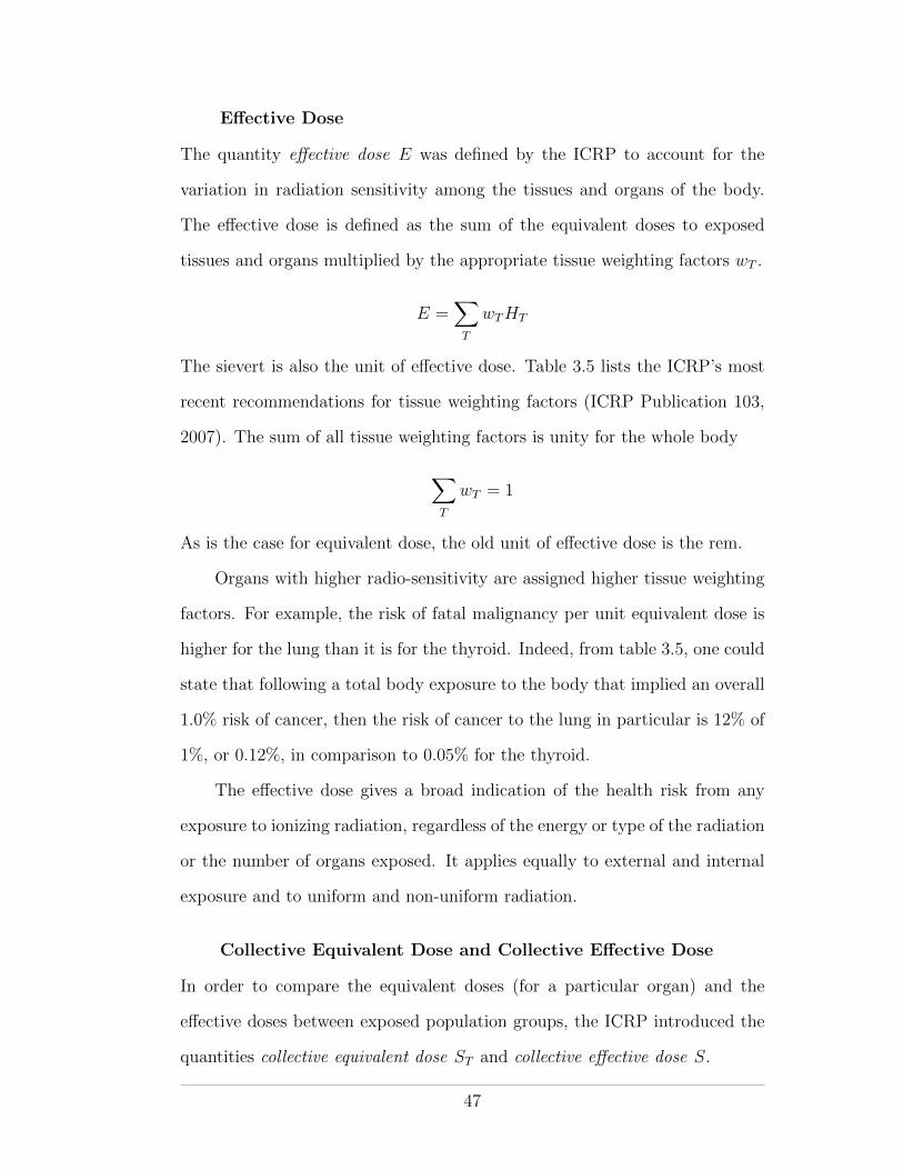
E↵ective Dose
The quantity e↵ective dose E was defined by the ICRP to account for the
variation in radiation sensitivity among the tissues and organs of the body.
The e↵ective dose is defined as the sum of the equivalent doses to exposed
tissues and organs multiplied by the appropriate tissue weighting factors wT .
E =X
T
wTHT
The sievert is also the unit of e↵ective dose. Table 3.5 lists the ICRP’s most
recent recommendations for tissue weighting factors (ICRP Publication 103,
2007). The sum of all tissue weighting factors is unity for the whole body
X
T
wT = 1
As is the case for equivalent dose, the old unit of e↵ective dose is the rem.
Organs with higher radio-sensitivity are assigned higher tissue weighting
factors. For example, the risk of fatal malignancy per unit equivalent dose is
higher for the lung than it is for the thyroid. Indeed, from table 3.5, one could
state that following a total body exposure to the body that implied an overall
1.0% risk of cancer, then the risk of cancer to the lung in particular is 12% of
1%, or 0.12%, in comparison to 0.05% for the thyroid.
The e↵ective dose gives a broad indication of the health risk from any
exposure to ionizing radiation, regardless of the energy or type of the radiation
or the number of organs exposed. It applies equally to external and internal
exposure and to uniform and non-uniform radiation.
Collective Equivalent Dose and Collective E↵ective Dose
In order to compare the equivalent doses (for a particular organ) and the
e↵ective doses between exposed population groups, the ICRP introduced the
quantities collective equivalent dose ST and collective e↵ective dose S.
47
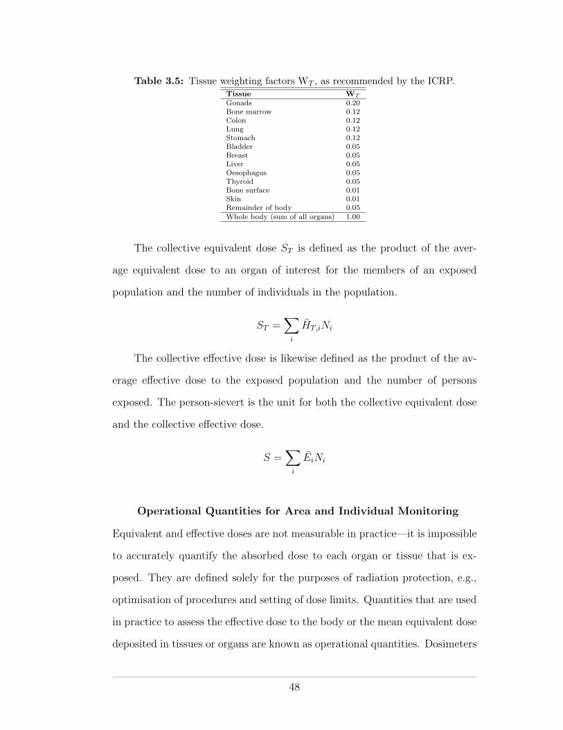
Table 3.5: Tissue weighting factors WT , as recommended by the ICRP.Tissue W
T
Gonads 0.20Bone marrow 0.12Colon 0.12Lung 0.12Stomach 0.12Bladder 0.05Breast 0.05Liver 0.05Oesophagus 0.05Thyroid 0.05Bone surface 0.01Skin 0.01Remainder of body 0.05Whole body (sum of all organs) 1.00
The collective equivalent dose ST is defined as the product of the aver-
age equivalent dose to an organ of interest for the members of an exposed
population and the number of individuals in the population.
ST =X
i
HT,iNi
The collective e↵ective dose is likewise defined as the product of the av-
erage e↵ective dose to the exposed population and the number of persons
exposed. The person-sievert is the unit for both the collective equivalent dose
and the collective e↵ective dose.
S =X
i
EiNi
Operational Quantities for Area and Individual Monitoring
Equivalent and e↵ective doses are not measurable in practice—it is impossible
to accurately quantify the absorbed dose to each organ or tissue that is ex-
posed. They are defined solely for the purposes of radiation protection, e.g.,
optimisation of procedures and setting of dose limits. Quantities that are used
in practice to assess the e↵ective dose to the body or the mean equivalent dose
deposited in tissues or organs are known as operational quantities. Dosimeters
48
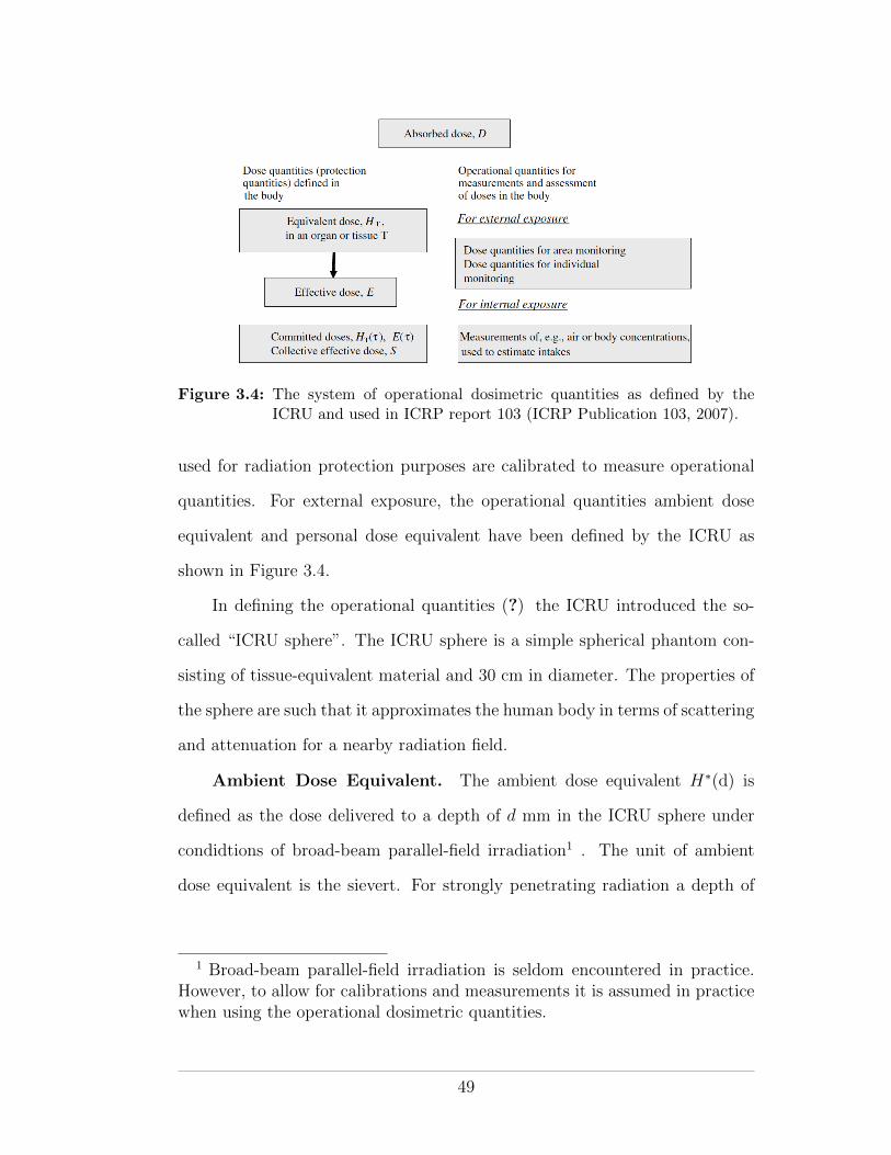
Figure 3.4: The system of operational dosimetric quantities as defined by theICRU and used in ICRP report 103 (ICRP Publication 103, 2007).
used for radiation protection purposes are calibrated to measure operational
quantities. For external exposure, the operational quantities ambient dose
equivalent and personal dose equivalent have been defined by the ICRU as
shown in Figure 3.4.
In defining the operational quantities (?) the ICRU introduced the so-
called “ICRU sphere”. The ICRU sphere is a simple spherical phantom con-
sisting of tissue-equivalent material and 30 cm in diameter. The properties of
the sphere are such that it approximates the human body in terms of scattering
and attenuation for a nearby radiation field.
Ambient Dose Equivalent. The ambient dose equivalent H⇤(d) is
defined as the dose delivered to a depth of d mm in the ICRU sphere under
condidtions of broad-beam parallel-field irradiation1 . The unit of ambient
dose equivalent is the sievert. For strongly penetrating radiation a depth of
1 Broad-beam parallel-field irradiation is seldom encountered in practice.However, to allow for calibrations and measurements it is assumed in practicewhen using the operational dosimetric quantities.
49
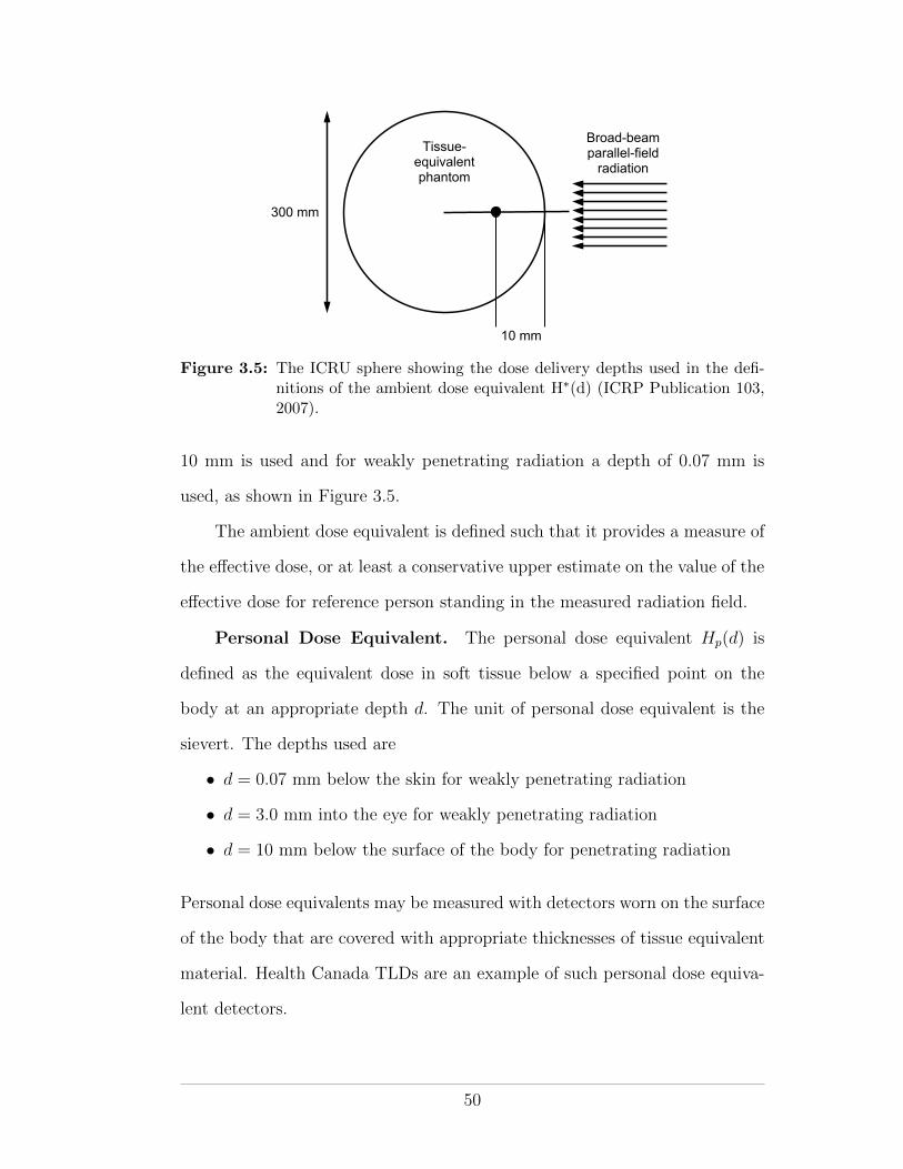
300 mm
10 mm
Broad-beam parallel-field
radiationTissue-
equivalent phantom
Figure 3.5: The ICRU sphere showing the dose delivery depths used in the defi-nitions of the ambient dose equivalent H⇤(d) (ICRP Publication 103,2007).
10 mm is used and for weakly penetrating radiation a depth of 0.07 mm is
used, as shown in Figure 3.5.
The ambient dose equivalent is defined such that it provides a measure of
the e↵ective dose, or at least a conservative upper estimate on the value of the
e↵ective dose for reference person standing in the measured radiation field.
Personal Dose Equivalent. The personal dose equivalent Hp(d) is
defined as the equivalent dose in soft tissue below a specified point on the
body at an appropriate depth d. The unit of personal dose equivalent is the
sievert. The depths used are
• d = 0.07 mm below the skin for weakly penetrating radiation
• d = 3.0 mm into the eye for weakly penetrating radiation
• d = 10 mm below the surface of the body for penetrating radiation
Personal dose equivalents may be measured with detectors worn on the surface
of the body that are covered with appropriate thicknesses of tissue equivalent
material. Health Canada TLDs are an example of such personal dose equiva-
lent detectors.
50
3.1.3 Biological Quantities
Some quantities of interest to the health physicist depend on biological factors
as well as physical factors. For example, radium-226 has chemical properties
similar to calcium. If ingested (as was the case for the radium dial workers,
see later in the course) radium may remain in the body for a long period of
time. The body treats it like calcium and deposits it in the bones. With its
long half-life (1 601 years) and long-term deposition in the body, radium-226
has the potential to cause radiation injury for the rest of the a↵ected person’s
life.
In health physics, several quantities are defined that take into account
both the physical and biological aspects of radiation exposure.
Biological and E↵ective Half Life
The biological half life of a substance is the time it takes for half of the sub-
stance to leave a compartment of a living organism. A compartment may be
an organ or a part of the body of interest. The biological decay constant is
synonymous with the radioactive decay constant and it gives the probability
of a unit substance leaving a biological compartment in unit time.
t 12 b
=ln2
�b
The e↵ective half life of a radionuclide in a compartment of a living or-
ganism accounts for both the biological and radioactive half lives of the ra-
dionuclide.
Inverse physical and biological half-lives add to give the inverse e↵ective
half life1
t 12 e
=1
t 12p
+1
t 12 b
51
Physical and biological decay constants add to give the e↵ective decay
constant
�e = �p + �b
Committed Dose
Upon injestion, a radionuclide will deliver dose for as long as it remains a
radioactive substance within the host’s body—either until the host dies or
the substance decays away (physicically or biologically or both), whichever
comes first. The commited dose is a quantity that accounts for the total
dose delivered to the host due to the injested radionuclide. In calculating the
committed dose the e↵ective half-life of the radionuclide in the host’s body is
used:
Dcom =
Z t
0
D0 ⇥ e��e
t dt
where D0 is the initial dose rate due to the radionuclide upon injestion, t is
the time since injestion and �e is the e↵ective half-life of the radionuclide.
When integrated, the committed dose is
Dcom =D0
�e
⇥1� e��t
⇤(3.8)
Two extreme situations are easily identified:
After an infinitely long time
When t ! 1 equation 3.8 reduces to
Dcom =D0
�e
For a long e↵ective half-life
For a long te, the radionuclide decays little over the time t and so
Dcom = D0 ⇥ t
52
In general t represents the remaining lifespan of the exposed individual.
For occupationally-exposed indviduals t is set at 50 years after injestion and
for a member of the public t is set up to age 70 years.
The Annual Limit of Intake
The annual limit of intake (ALI) is defined as that quantity of activity of a
radionuclide that would lead to the annual dose limit if inhaled or ingested by
a “reference person”. ALI considers the e↵ective half life of the radionuclide
as per the committed dose. It will be discussed later in relation to dose limits.
Relative Biological E↵ectiveness
The relative biological e↵ectiveness (RBE) is a quantity that is used in radio-
biology and health physics to compare the e↵ectiveness of di↵erent radiations
at producing biological damage. It uses the damage (of a particular type) due
to 250 keV X rays, as a normalization factor. RBE for a particular radiation is
defined as the ratio of the dose from 250 keV X rays needed to produce a given
biological e↵ect to the dose of the particular radiation needed to produce the
same biological e↵ect.
RBE =Dose from 250 keV to a tissue
Dose from a test radiation for same biological e↵ect
For example, it only takes one sixteenth of the dose of 14 MeV neutrons
to kill cockroach embryos as it does for 250 keV X rays to kill them. Thus,
the RBE for cockroach embryo lethality is 16 for 14 MeV neutrons.
The RBE for 250 keV X rays is, by definition, always one for any biological
e↵ect.
3.1.4 Legal/Regulatory Quantities
Several quantities are defined for legal/regulatory convenience. They are gen-
erally based on physical quantities and are used to set regulatory limits. They
53
will depend on the jurisdiction where they are defined. Two quantities of inter-
est to health physicists in Canada, the Exemption Quantity and the Transport
Index are discussed here.
Exemption Quantity
An exemption quantity (EQ) is defined as the quantity of a radionuclide (ex-
pressed in Bq) below which conditions are not imposed by the Canadian Nu-
clear Safety Commission. Licenses and radiation warning signs are mandated
when EQs are exceeded. The following conditions apply:
• For a quantity of radionuclide with an EQ < 1, no special conditions are
attached
• For a quantity of radionuclide with an EQ > 1, a license is required
• For a quantity of radionuclide with an EQ > 100, a radiation warning
sign is required
• For a quantity of radionuclide with an EQ > 10 000, written approval
(licensing) from the CNSC is required before the radionuclide may be
used
Transport Index
The transport index (TI) is defined as the maximum radiation level in mrem/h
at one meter from the surface of a single, isolated, undamaged package con-
taining radioactive material.
The definition of the TI can be found in Transport Canada’s Emergency
Response Guidebook 2008, which is available online. The TI will be discussed
again in relation to radiation regulations.
3.2 Radiation Detectors and Dosimeters
Under normal circumstances, humans cannot see, feel, or otherwise detect
radiation. As such, we rely on specially-designed instruments to detect and
54
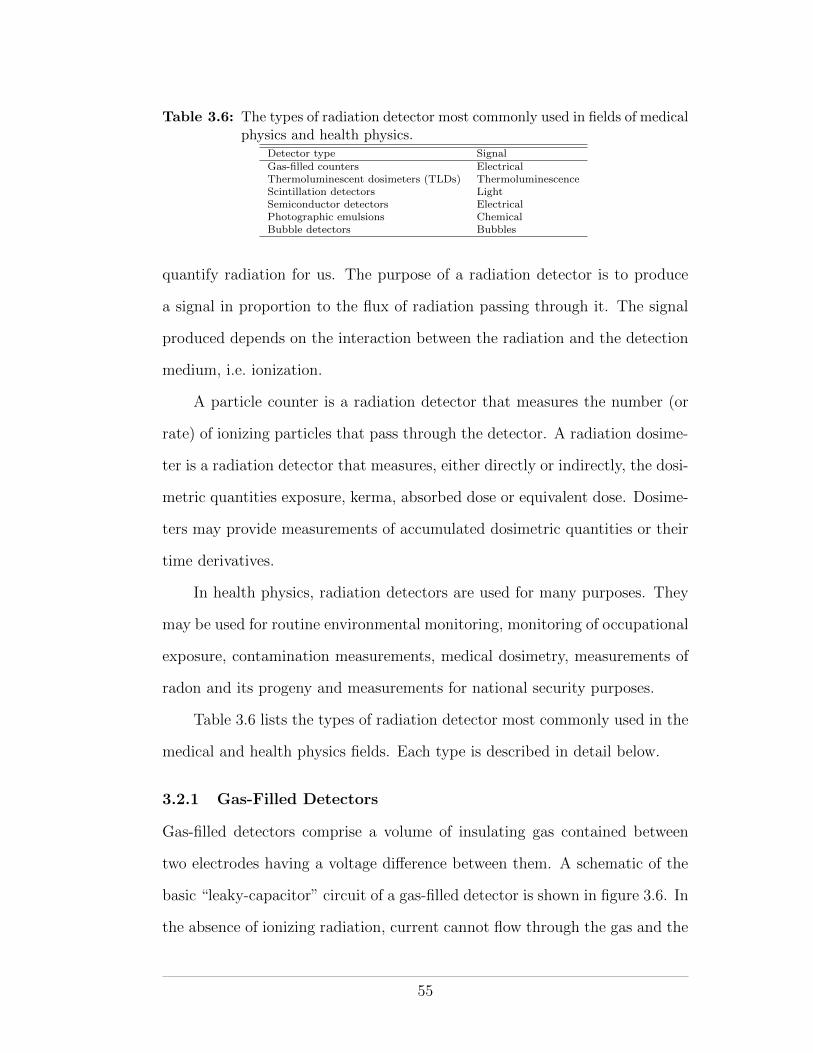
Table 3.6: The types of radiation detector most commonly used in fields of medicalphysics and health physics.
Detector type SignalGas-filled counters ElectricalThermoluminescent dosimeters (TLDs) ThermoluminescenceScintillation detectors LightSemiconductor detectors ElectricalPhotographic emulsions ChemicalBubble detectors Bubbles
quantify radiation for us. The purpose of a radiation detector is to produce
a signal in proportion to the flux of radiation passing through it. The signal
produced depends on the interaction between the radiation and the detection
medium, i.e. ionization.
A particle counter is a radiation detector that measures the number (or
rate) of ionizing particles that pass through the detector. A radiation dosime-
ter is a radiation detector that measures, either directly or indirectly, the dosi-
metric quantities exposure, kerma, absorbed dose or equivalent dose. Dosime-
ters may provide measurements of accumulated dosimetric quantities or their
time derivatives.
In health physics, radiation detectors are used for many purposes. They
may be used for routine environmental monitoring, monitoring of occupational
exposure, contamination measurements, medical dosimetry, measurements of
radon and its progeny and measurements for national security purposes.
Table 3.6 lists the types of radiation detector most commonly used in the
medical and health physics fields. Each type is described in detail below.
3.2.1 Gas-Filled Detectors
Gas-filled detectors comprise a volume of insulating gas contained between
two electrodes having a voltage di↵erence between them. A schematic of the
basic “leaky-capacitor” circuit of a gas-filled detector is shown in figure 3.6. In
the absence of ionizing radiation, current cannot flow through the gas and the
55
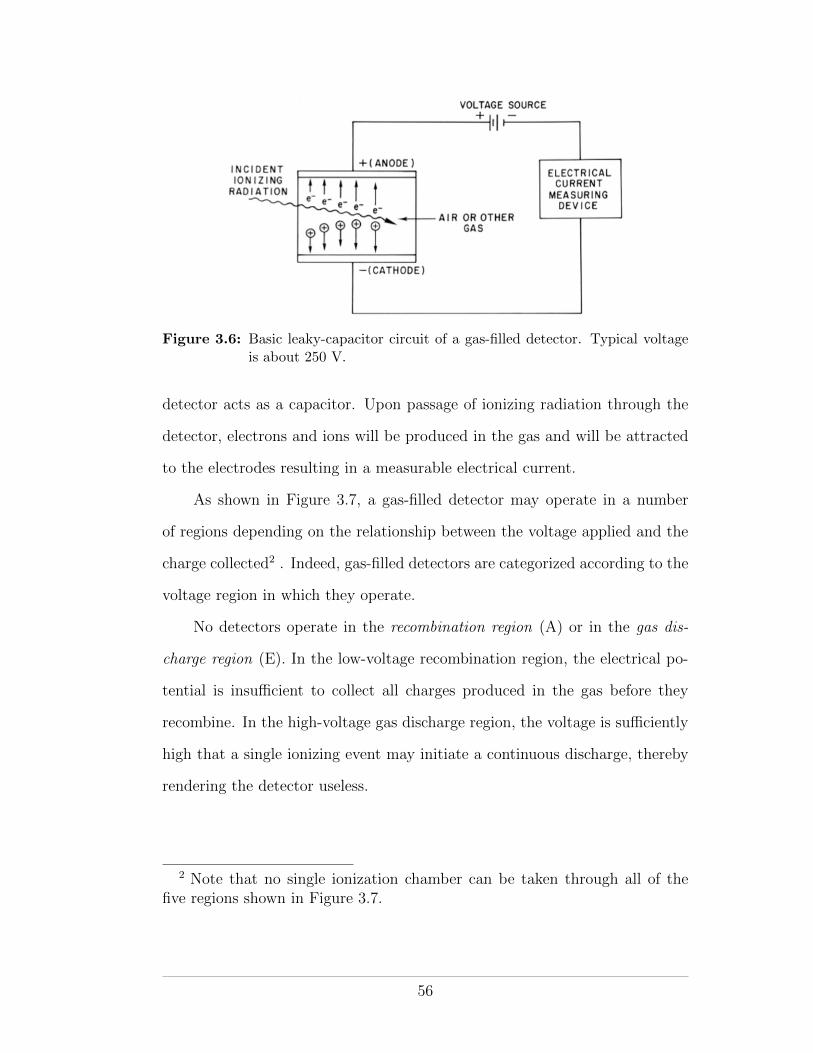
Figure 3.6: Basic leaky-capacitor circuit of a gas-filled detector. Typical voltageis about 250 V.
detector acts as a capacitor. Upon passage of ionizing radiation through the
detector, electrons and ions will be produced in the gas and will be attracted
to the electrodes resulting in a measurable electrical current.
As shown in Figure 3.7, a gas-filled detector may operate in a number
of regions depending on the relationship between the voltage applied and the
charge collected2 . Indeed, gas-filled detectors are categorized according to the
voltage region in which they operate.
No detectors operate in the recombination region (A) or in the gas dis-
charge region (E). In the low-voltage recombination region, the electrical po-
tential is insu�cient to collect all charges produced in the gas before they
recombine. In the high-voltage gas discharge region, the voltage is su�ciently
high that a single ionizing event may initiate a continuous discharge, thereby
rendering the detector useless.
2 Note that no single ionization chamber can be taken through all of thefive regions shown in Figure 3.7.
56
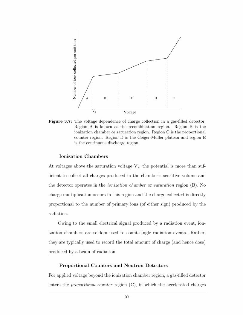
Num
ber
of
ions
coll
ecte
d p
er u
nit
tim
e
VoltageVS
A B C D E
Figure 3.7: The voltage dependence of charge collection in a gas-filled detector.Region A is known as the recombination region. Region B is theionization chamber or saturation region. Region C is the proportionalcounter region. Region D is the Geiger-Muller plateau and region Eis the continuous discharge region.
Ionization Chambers
At voltages above the saturation voltage Vs, the potential is more than suf-
ficient to collect all charges produced in the chamber’s sensitive volume and
the detector operates in the ionization chamber or saturation region (B). No
charge multiplication occurs in this region and the charge collected is directly
proportional to the number of primary ions (of either sign) produced by the
radiation.
Owing to the small electrical signal produced by a radiation event, ion-
ization chambers are seldom used to count single radiation events. Rather,
they are typically used to record the total amount of charge (and hence dose)
produced by a beam of radiation.
Proportional Counters and Neutron Detectors
For applied voltage beyond the ionization chamber region, a gas-filled detector
enters the proportional counter region (C), in which the accelerated charges
57
have su�cient kinetic energy to induce further ionizations through collision
interactions. At any given voltage, the output electrical signal is directly pro-
portional to the energy deposited by the primary radiation and primary parti-
cle identification, through the use of an appropriate discriminator, is possible.
Compared to ionization chambers (for which primary particle identification
is also possible, for the same reason), proportional counters produce larger
output signals and so require less amplification, making them more practical.
In radiation protection, proportional counters are frequently encountered
as neutron detectors. Since primary particle identification is possible, the
photon background can easily be discriminated against. The slow neutron sig-
nal (from indirect neutron ionization) is enhanced by coating the chamber wall
with a boron compound, or by filling the detector volume with BF3 gas. Alpha
particles produced in the 10B(n,↵)7Li reaction are easily discriminated from
any gamma-ray background. Fast neutrons may be moderated by surrounding
the detector with a moderator of hydrogenous material.
Geiger-Muller Detectors
At high voltages, gas-filled detectors operate in the Geiger-Muller (GM) re-
gion (D). In this plateau region, accelerated electrons excite gas molecules and
produce UV radiation. The UV radiation, in turn, induces further ionization
such that an avalanche of electron-ion pairs propagates through the gas vol-
ume. The output electrical pulse is very strong but is independent of the type
or energy of the primary radiation. Accordingly, GM detectors are very sen-
sitive and can detect all forms of ionizing radiation. They are commonly used
as survey meters for radiation protection purposes.
Despite their excellent sensitivity, GM detectors have several disadvan-
tages for surveying radiation therapy installations. They are unable to identify
particle type since all radiations produce the same signal, and they su↵er from
58
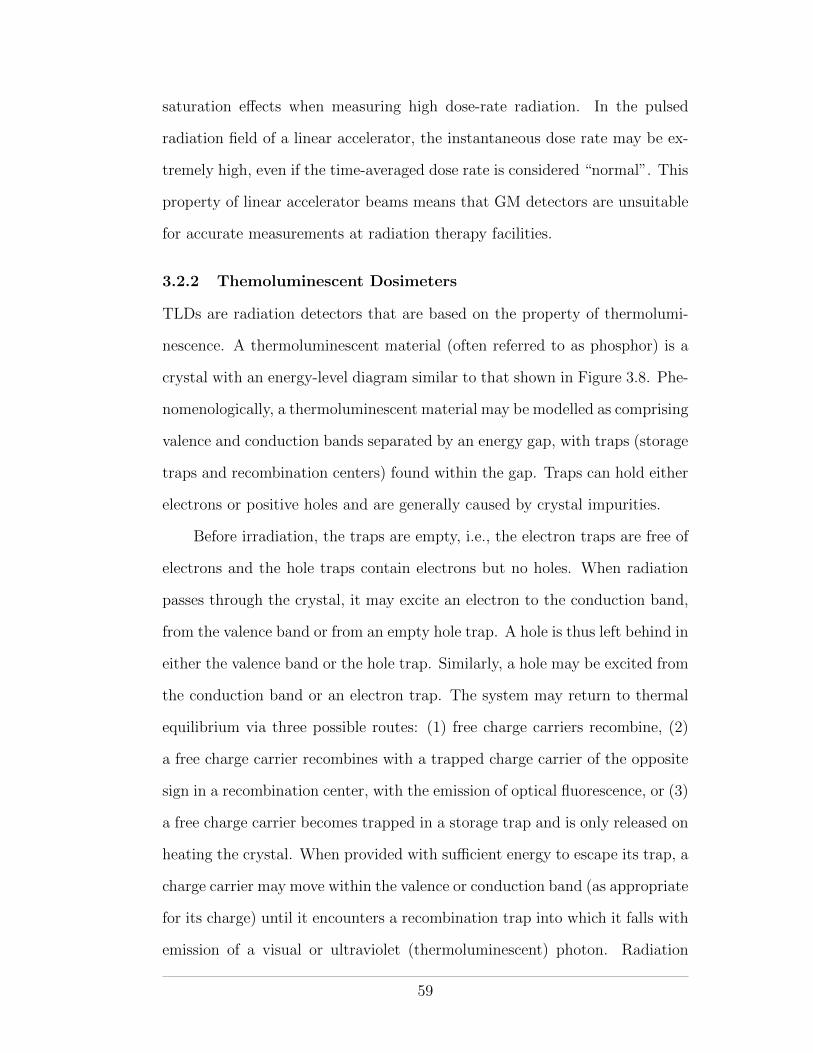
saturation e↵ects when measuring high dose-rate radiation. In the pulsed
radiation field of a linear accelerator, the instantaneous dose rate may be ex-
tremely high, even if the time-averaged dose rate is considered “normal”. This
property of linear accelerator beams means that GM detectors are unsuitable
for accurate measurements at radiation therapy facilities.
3.2.2 Themoluminescent Dosimeters
TLDs are radiation detectors that are based on the property of thermolumi-
nescence. A thermoluminescent material (often referred to as phosphor) is a
crystal with an energy-level diagram similar to that shown in Figure 3.8. Phe-
nomenologically, a thermoluminescent material may be modelled as comprising
valence and conduction bands separated by an energy gap, with traps (storage
traps and recombination centers) found within the gap. Traps can hold either
electrons or positive holes and are generally caused by crystal impurities.
Before irradiation, the traps are empty, i.e., the electron traps are free of
electrons and the hole traps contain electrons but no holes. When radiation
passes through the crystal, it may excite an electron to the conduction band,
from the valence band or from an empty hole trap. A hole is thus left behind in
either the valence band or the hole trap. Similarly, a hole may be excited from
the conduction band or an electron trap. The system may return to thermal
equilibrium via three possible routes: (1) free charge carriers recombine, (2)
a free charge carrier recombines with a trapped charge carrier of the opposite
sign in a recombination center, with the emission of optical fluorescence, or (3)
a free charge carrier becomes trapped in a storage trap and is only released on
heating the crystal. When provided with su�cient energy to escape its trap, a
charge carrier may move within the valence or conduction band (as appropriate
for its charge) until it encounters a recombination trap into which it falls with
emission of a visual or ultraviolet (thermoluminescent) photon. Radiation
59
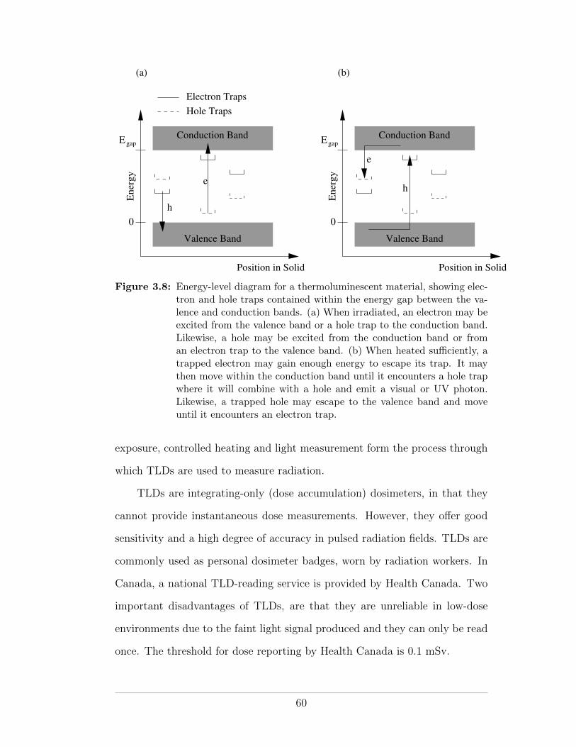
Egap EgapConduction Band
Valence Band
Position in Solid
Ener
gy
0
Conduction Band
Valence Band
Position in Solid
Ener
gy
0
Electron Traps
Hole Traps
e
h
h
e
(a) (b)
Figure 3.8: Energy-level diagram for a thermoluminescent material, showing elec-tron and hole traps contained within the energy gap between the va-lence and conduction bands. (a) When irradiated, an electron may beexcited from the valence band or a hole trap to the conduction band.Likewise, a hole may be excited from the conduction band or froman electron trap to the valence band. (b) When heated su�ciently, atrapped electron may gain enough energy to escape its trap. It maythen move within the conduction band until it encounters a hole trapwhere it will combine with a hole and emit a visual or UV photon.Likewise, a trapped hole may escape to the valence band and moveuntil it encounters an electron trap.
exposure, controlled heating and light measurement form the process through
which TLDs are used to measure radiation.
TLDs are integrating-only (dose accumulation) dosimeters, in that they
cannot provide instantaneous dose measurements. However, they o↵er good
sensitivity and a high degree of accuracy in pulsed radiation fields. TLDs are
commonly used as personal dosimeter badges, worn by radiation workers. In
Canada, a national TLD-reading service is provided by Health Canada. Two
important disadvantages of TLDs, are that they are unreliable in low-dose
environments due to the faint light signal produced and they can only be read
once. The threshold for dose reporting by Health Canada is 0.1 mSv.
60
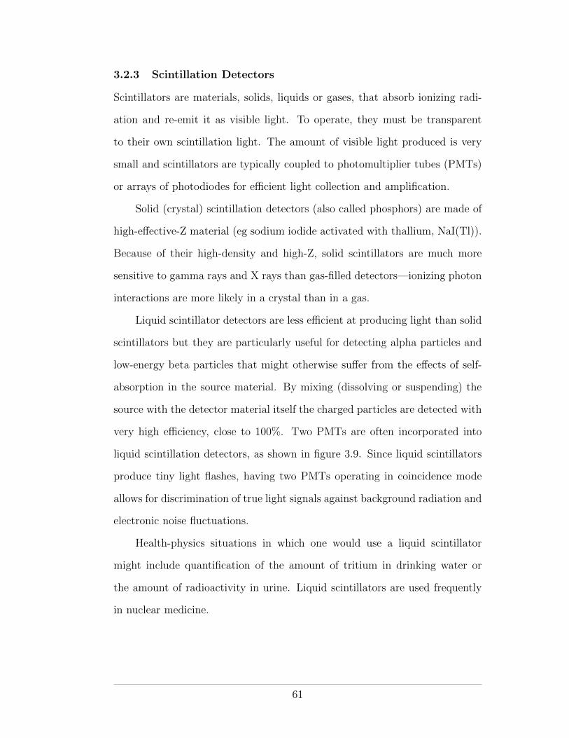
3.2.3 Scintillation Detectors
Scintillators are materials, solids, liquids or gases, that absorb ionizing radi-
ation and re-emit it as visible light. To operate, they must be transparent
to their own scintillation light. The amount of visible light produced is very
small and scintillators are typically coupled to photomultiplier tubes (PMTs)
or arrays of photodiodes for e�cient light collection and amplification.
Solid (crystal) scintillation detectors (also called phosphors) are made of
high-e↵ective-Z material (eg sodium iodide activated with thallium, NaI(Tl)).
Because of their high-density and high-Z, solid scintillators are much more
sensitive to gamma rays and X rays than gas-filled detectors—ionizing photon
interactions are more likely in a crystal than in a gas.
Liquid scintillator detectors are less e�cient at producing light than solid
scintillators but they are particularly useful for detecting alpha particles and
low-energy beta particles that might otherwise su↵er from the e↵ects of self-
absorption in the source material. By mixing (dissolving or suspending) the
source with the detector material itself the charged particles are detected with
very high e�ciency, close to 100%. Two PMTs are often incorporated into
liquid scintillation detectors, as shown in figure 3.9. Since liquid scintillators
produce tiny light flashes, having two PMTs operating in coincidence mode
allows for discrimination of true light signals against background radiation and
electronic noise fluctuations.
Health-physics situations in which one would use a liquid scintillator
might include quantification of the amount of tritium in drinking water or
the amount of radioactivity in urine. Liquid scintillators are used frequently
in nuclear medicine.
61
Figure 3.9: Schematic of a liquid scintillation detector with two PMTs operatingin coincidence mode. Figure from Cherry et al. (2003).
Scintillators are commonly used as gamma-ray spectrometers since the
amount of light emitted is proportional to the energy deposited by the incident
ionizing radiation.
Well-type scintillation counters are solid scintillator counters designed
such that a test-tube holding a sample radioactive substance may be inserted
into a hole in the scintillator. A cross-sectional view of a well-counter detector
is shown in figure 3.10. Well counters have excellent geometric e�ciency and
are typically surrounded by lead shielding to reduce background contamina-
tion. They are used frequently in health physics and nuclear medicine.
3.2.4 Semiconductor Detectors
Semiconductor detectors are essentially solid-state ionization chambers—ionizing
radiation interacts in the sensitive volume to produce ions than in turn produce
a measurable electronic pulse. Compared with gas-filled detectors, however,
semiconductor detectors o↵er greater sensitivity and higher energy resolution.
Only ⇠3.5 eV is required to produce an ion-pair (electron and hole) in a semi-
conductor, whereas 33.97 eV is required to produce an ion-pair in air. The
62
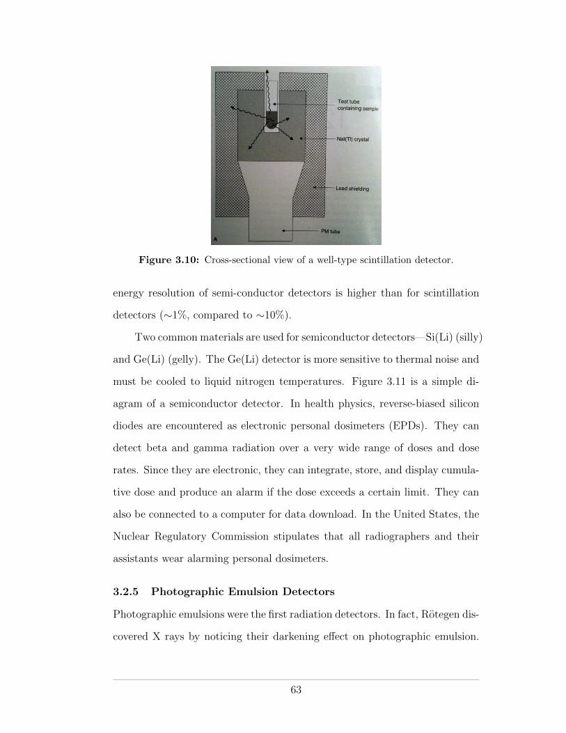
Figure 3.10: Cross-sectional view of a well-type scintillation detector.
energy resolution of semi-conductor detectors is higher than for scintillation
detectors (⇠1%, compared to ⇠10%).
Two common materials are used for semiconductor detectors—Si(Li) (silly)
and Ge(Li) (gelly). The Ge(Li) detector is more sensitive to thermal noise and
must be cooled to liquid nitrogen temperatures. Figure 3.11 is a simple di-
agram of a semiconductor detector. In health physics, reverse-biased silicon
diodes are encountered as electronic personal dosimeters (EPDs). They can
detect beta and gamma radiation over a very wide range of doses and dose
rates. Since they are electronic, they can integrate, store, and display cumula-
tive dose and produce an alarm if the dose exceeds a certain limit. They can
also be connected to a computer for data download. In the United States, the
Nuclear Regulatory Commission stipulates that all radiographers and their
assistants wear alarming personal dosimeters.
3.2.5 Photographic Emulsion Detectors
Photographic emulsions were the first radiation detectors. In fact, Rotegen dis-
covered X rays by noticing their darkening e↵ect on photographic emulsion.
63
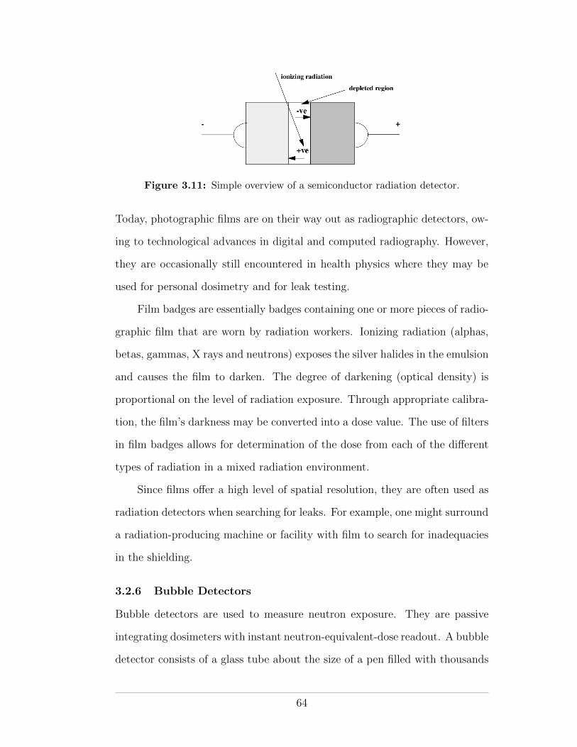
Figure 3.11: Simple overview of a semiconductor radiation detector.
Today, photographic films are on their way out as radiographic detectors, ow-
ing to technological advances in digital and computed radiography. However,
they are occasionally still encountered in health physics where they may be
used for personal dosimetry and for leak testing.
Film badges are essentially badges containing one or more pieces of radio-
graphic film that are worn by radiation workers. Ionizing radiation (alphas,
betas, gammas, X rays and neutrons) exposes the silver halides in the emulsion
and causes the film to darken. The degree of darkening (optical density) is
proportional on the level of radiation exposure. Through appropriate calibra-
tion, the film’s darkness may be converted into a dose value. The use of filters
in film badges allows for determination of the dose from each of the di↵erent
types of radiation in a mixed radiation environment.
Since films o↵er a high level of spatial resolution, they are often used as
radiation detectors when searching for leaks. For example, one might surround
a radiation-producing machine or facility with film to search for inadequacies
in the shielding.
3.2.6 Bubble Detectors
Bubble detectors are used to measure neutron exposure. They are passive
integrating dosimeters with instant neutron-equivalent-dose readout. A bubble
detector consists of a glass tube about the size of a pen filled with thousands
64
of superheated liquid drops in a stabilizing matrix. When struck by a neutron
the potential energy contained within an individual drop is released via a
vaporising explosion that produces an audible pop and a visible bubble. The
number of bubbles produced is directly proportional to the neutron-equivalent
dose H. The bubbles may be counted visually or by a machine. Bubble
detectors have a useful lifetime of about three months during which they may
be recycled and reused many times. A screw at the end of the tube may be
used to re-pressurize the matrix and remove the bubbles.
3.2.7 Calibration of Radiation Detectors
Calibration of radiation detectors used for health physics measurements should
be carried out at least once per year by a qualified expert. Calibration is
achieved by exposing a detector to a known radiation level and adjusting the
detector to read the radiation level. The “known” radiation level should be
confirmed using a detector with a calibration of its own traceable to an o�cial
standards laboratory, such as the National Research Council (NRC) in Ottawa,
Ontario.
Calibration of radiation survey meters is typically performed using some
form of shadow-cone technique. Using the shadow-cone technique, a radioac-
tive source with a known exposure rate constant (or air-kerma strength) may
be used to calibrate a radiation detector positioned at a measured distance
away. The method is illustrated in Figure 3.12. Accounting for the fall-o↵ in
exposure as a function of distance, due to the inverse-square law and atten-
uation in the intervening medium (air), and considering the time over which
the source is exposed, the exposure reading on the detector may be predicted.
The actual reading on the device, however, will be larger than that predicted,
owing to radiation scattered o↵ the surroundings and back to the detector. Al-
though very di�cult to predict, the scatter component is easily measured by
65
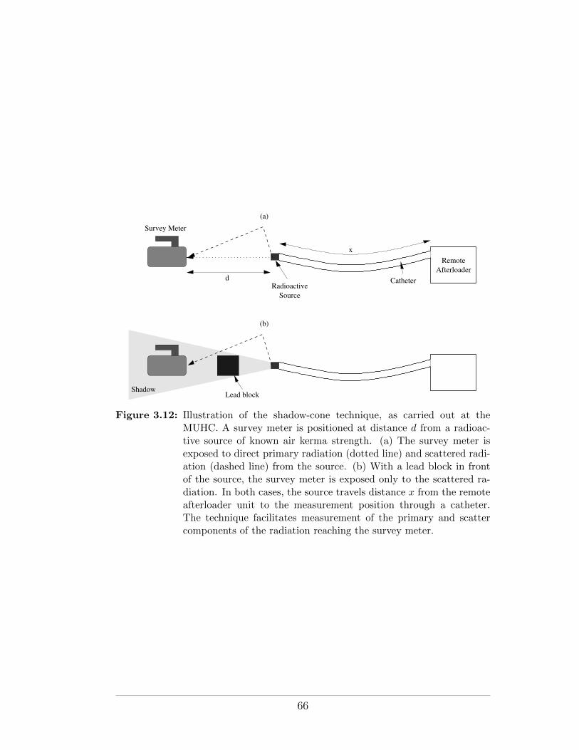
Remote
Afterloader
Radioactive
Source
x
Survey Meter
Catheter
ShadowLead block
d
(a)
(b)
Figure 3.12: Illustration of the shadow-cone technique, as carried out at theMUHC. A survey meter is positioned at distance d from a radioac-tive source of known air kerma strength. (a) The survey meter isexposed to direct primary radiation (dotted line) and scattered radi-ation (dashed line) from the source. (b) With a lead block in frontof the source, the survey meter is exposed only to the scattered ra-diation. In both cases, the source travels distance x from the remoteafterloader unit to the measurement position through a catheter.The technique facilitates measurement of the primary and scattercomponents of the radiation reaching the survey meter.
66
placing a block of attenuating material between source and detector, such that
the detector is within the “shadow” of the block and the primary radiation is
prevented from reaching the detector. The resulting scatter-subtracted expo-
sure may be compared with the predicted value and hence used to calibrate
the detector.
The shadow-cone technique is a nice example of how the radiation level at
a point (the detector) depends on distance from the source, the exposure time,
the shielding (in this case, attenuation in the air) and scatter. The technique
also illustrates the use of the exposure-rate constant.
3.2.8 Radiation Detection in Practice
Radiation detectors come in a variety of flavors. Particle counting detectors
measure counts and are useful for measuring half-lives and activities. Solid
scintillation counters have high e�ciencies for measuring gamma rays and liq-
uid scintillation counters are useful for measuring radiation from liquid sources
or weak, self-absorbing, sources. Well counters are used for wipe testing and
high-e�ciency counting. Survey meters are used when checking for leaks or
looking for a source of radiation. Ionization chambers are used for accurate
dose measurements. Films are used when spatial resolution is needed, semi-
conductors and scintillators when energy resolution is important.
Regardless of detector type or function, the following checks should be
performed before a detector is used for health physics purposes:
• The detector should be sensitive to the type of radiation to be measured
• The detector must have been calibrated within the last year by a qualified
expert
• The detector should pass a battery test, if appropriate
• The detector should pass a rate test (using a pulse generator), if appro-
priate
67
• The detector should pass a self-check using a check source
68
CHAPTER 4Biological E↵ects of Radiation
Ionizing radiation has, by definition, the potential to alter the material through
which it passes—it may ionize the atoms and molecules it encounters. This is
true regardless of the material, be it organic or inorganic, alive or dead. For
biological materials, however, ionizing radiation has the particular ability to
a↵ect lethal injury.
When absorbed in biological systems, radiation may cause initial injury
at the microscopic level. In some cases the microscopic damage may be re-
paired and go unnoticed, in other cases, it may ultimately manifest itself
macroscopically as an observable e↵ect. Macroscopic e↵ects may result from
a large radiation exposure that causes su�cient microscopic damage to be no-
ticeable at the macroscopic level, or they may be the propagated long-term
consequences of just a single radiation-induced error in the genetic code.
The e↵ects of radiation exposure, particularly at relatively large doses, are
well studied. Indeed, the biological e↵ects of radiation exposure are the basis
of radiation therapy. In this chapter we will examine the biological e↵ects of
radiation and the relationship between dose and radiation-induced injury.
4.1 Sources of Information
Quality data for studies into the e↵ects of radiation exposure are hard to
come by. On one hand, data pertaining to very high doses of radiation are
rare since very large exposures seldom occur. On the other hand, low-dose
data are compromised by a dearth of etiologic (causative) evidence pointing
exclusively to radiation. The following sources of information do exist:
69
• Atomic bomb survivors from Hiroshima and Nagasaki (thousands of peo-
ple)
• Marshall islanders exposed to fallout from atmospheric nuclear weapons
tests (hundreds-thousands of people)
• Victims of accidents at nuclear installations (eg Chernobyl, USSR/Ukraine,
115 cases of acute radiation sickness and 28 deaths)
• Victims of accidents involving medical radiation devices (eg Goiania,
Brazil, 48 hospitalizations and 4 deaths)
• Patients exposed to medical radiation for treatment or diagnosis of dis-
ease
• Miners exposed to uranium/radon and its decay products
• Residents exposed to radon in the home
• Workers exposed to radium-226 in luminous paint
• Workers exposed to medical radiation
• Animal studies
4.2 The Human Organism
Human beings are organisms. As shown in figure 4.1, we comprise organs
that comprise tissues that are made up of cells. Cells consist of cytoplasm
containing organelles and a nucleus containing DNA. At the most basic level,
cells are made up of protoplasm—organic and inorganic compounds. After all,
we are what we eat!
It is our DNA that allows us to survive as individuals and as a species.
It enables our cells to divide and multiply (ie growth) and it encodes the
genes that we pass to our descendants when we reproduce. Human cells are
doubly-coded with DNA (one set of DNA from each parent) and they are
either somatic or germ cell. Somatic cells divide by mitosis, germ cells by
meiosis.
70
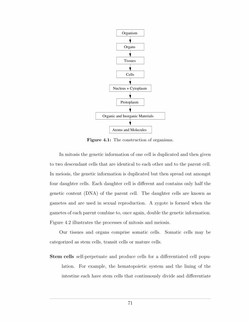
Organism
Organs
Tissues
Cells
Nucleus + Cytoplasm
Protoplasm
Atoms and Molecules
Organic and Inorganic Materials
Figure 4.1: The construction of organisms.
In mitosis the genetic information of one cell is duplicated and then given
to two descendant cells that are identical to each other and to the parent cell.
In meiosis, the genetic information is duplicated but then spread out amongst
four daughter cells. Each daughter cell is di↵erent and contains only half the
genetic content (DNA) of the parent cell. The daughter cells are known as
gametes and are used in sexual reproduction. A zygote is formed when the
gametes of each parent combine to, once again, double the genetic information.
Figure 4.2 illustrates the processes of mitosis and meiosis.
Our tissues and organs comprise somatic cells. Somatic cells may be
categorized as stem cells, transit cells or mature cells.
Stem cells self-perpetuate and produce cells for a di↵erentiated cell popu-
lation. For example, the hematopoietic system and the lining of the
intestine each have stem cells that continuously divide and di↵erentiate
71
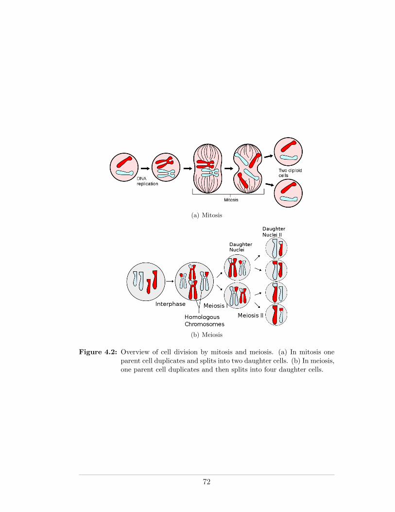
(a) Mitosis
(b) Meiosis
Figure 4.2: Overview of cell division by mitosis and meiosis. (a) In mitosis oneparent cell duplicates and splits into two daughter cells. (b) In meiosis,one parent cell duplicates and then splits into four daughter cells.
72
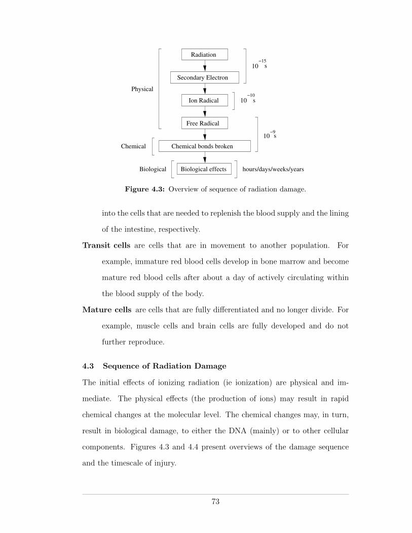
Radiation
Ion Radical
Free Radical
Chemical bonds broken
Biological effects
Secondary Electron
Physical
Chemical
Biological
10
10−15
−10
hours/days/weeks/years
10−9
s
s
s
Figure 4.3: Overview of sequence of radiation damage.
into the cells that are needed to replenish the blood supply and the lining
of the intestine, respectively.
Transit cells are cells that are in movement to another population. For
example, immature red blood cells develop in bone marrow and become
mature red blood cells after about a day of actively circulating within
the blood supply of the body.
Mature cells are cells that are fully di↵erentiated and no longer divide. For
example, muscle cells and brain cells are fully developed and do not
further reproduce.
4.3 Sequence of Radiation Damage
The initial e↵ects of ionizing radiation (ie ionization) are physical and im-
mediate. The physical e↵ects (the production of ions) may result in rapid
chemical changes at the molecular level. The chemical changes may, in turn,
result in biological damage, to either the DNA (mainly) or to other cellular
components. Figures 4.3 and 4.4 present overviews of the damage sequence
and the timescale of injury.
73
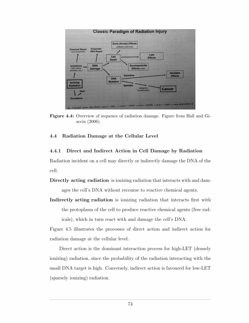
Figure 4.4: Overview of sequence of radiation damage. Figure from Hall and Gi-accia (2006).
4.4 Radiation Damage at the Cellular Level
4.4.1 Direct and Indirect Action in Cell Damage by Radiation
Radiation incident on a cell may directly or indirectly damage the DNA of the
cell.
Directly acting radiation is ionizing radiation that interacts with and dam-
ages the cell’s DNA without recourse to reactive chemical agents.
Indirectly acting radiation is ionizing radiation that interacts first with
the protoplasm of the cell to produce reactive chemical agents (free rad-
icals), which in turn react with and damage the cell’s DNA.
Figure 4.5 illustrates the processes of direct action and indirect action for
radiation damage at the cellular level.
Direct action is the dominant interaction process for high-LET (densely
ionizing) radiation, since the probability of the radiation interacting with the
small DNA target is high. Conversely, indirect action is favoured for low-LET
(sparsely ionizing) radiation.
74
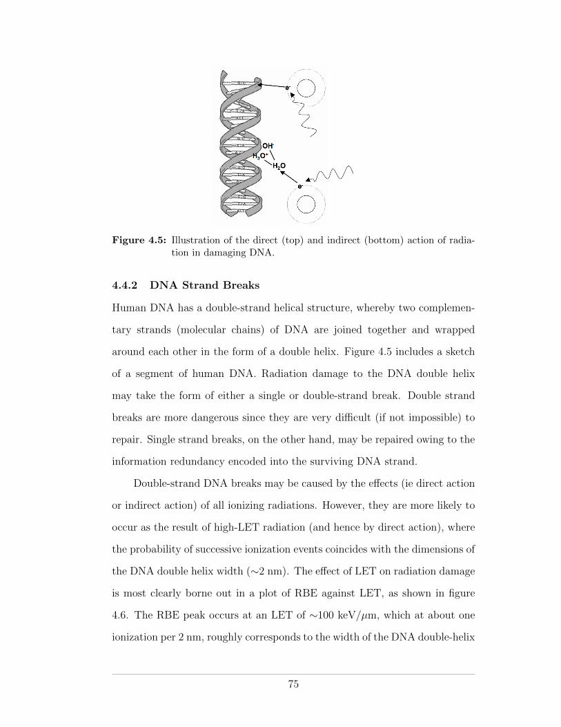
Figure 4.5: Illustration of the direct (top) and indirect (bottom) action of radia-tion in damaging DNA.
4.4.2 DNA Strand Breaks
Human DNA has a double-strand helical structure, whereby two complemen-
tary strands (molecular chains) of DNA are joined together and wrapped
around each other in the form of a double helix. Figure 4.5 includes a sketch
of a segment of human DNA. Radiation damage to the DNA double helix
may take the form of either a single or double-strand break. Double strand
breaks are more dangerous since they are very di�cult (if not impossible) to
repair. Single strand breaks, on the other hand, may be repaired owing to the
information redundancy encoded into the surviving DNA strand.
Double-strand DNA breaks may be caused by the e↵ects (ie direct action
or indirect action) of all ionizing radiations. However, they are more likely to
occur as the result of high-LET radiation (and hence by direct action), where
the probability of successive ionization events coincides with the dimensions of
the DNA double helix width (⇠2 nm). The e↵ect of LET on radiation damage
is most clearly borne out in a plot of RBE against LET, as shown in figure
4.6. The RBE peak occurs at an LET of ⇠100 keV/µm, which at about one
ionization per 2 nm, roughly corresponds to the width of the DNA double-helix
75
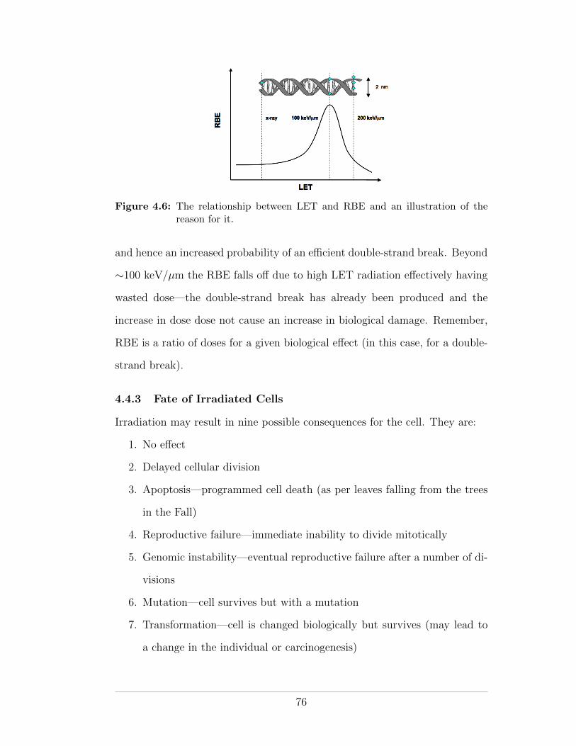
Figure 4.6: The relationship between LET and RBE and an illustration of thereason for it.
and hence an increased probability of an e�cient double-strand break. Beyond
⇠100 keV/µm the RBE falls o↵ due to high LET radiation e↵ectively having
wasted dose—the double-strand break has already been produced and the
increase in dose dose not cause an increase in biological damage. Remember,
RBE is a ratio of doses for a given biological e↵ect (in this case, for a double-
strand break).
4.4.3 Fate of Irradiated Cells
Irradiation may result in nine possible consequences for the cell. They are:
1. No e↵ect
2. Delayed cellular division
3. Apoptosis—programmed cell death (as per leaves falling from the trees
in the Fall)
4. Reproductive failure—immediate inability to divide mitotically
5. Genomic instability—eventual reproductive failure after a number of di-
visions
6. Mutation—cell survives but with a mutation
7. Transformation—cell is changed biologically but survives (may lead to
a change in the individual or carcinogenesis)
76
8. Bystander e↵ects—the irradiated cell sends signal to neighbouring unir-
radiated cells that induces genetic damage in them
9. Adaptive responses—the irradiated cell adapts to radiation and becomes
more resistant to subsequent radiation
4.5 Radiation Injury at the Macroscopic Level
Biological damage to a large number of cells may be significant enough to
be macroscopically noticeable in the short to medium term (hours to days).
This is particularly true in the case of damage to stem cells that may result
in an inability to replenish a needed supply of mature cells. For example, the
hematopoietic syndrome (described below) becomes noticeable in an individual
about 3 weeks after exposure as mature circulating blood cells die o↵ but are
not replaced due to the depletion of hematopoietic stem cells.
Biological damage to just one or a few cells is not immediately noticeable
at the macroscopic level. However, even a small amount of DNA damage,
if propagated through cell division, may result in long-term e↵ects. Such
long-term e↵ects may include cancer if somatic cells are injured, or steril-
ity/generational e↵ects if germ cells are injured.
Depending on the number of cells a↵ected, the macroscopic biological
e↵ects of radiation can be divided into deterministic and stochastic e↵ects.
Deterministic e↵ects are generally (but not always) the result of large radiation
doses in which many cells are simultaneously injured. Stochastic e↵ects involve
generally (but, again, not always) smaller radiation doses, few cells, and entail
radiation-induced carcinogenesis.
In all cases, the likelihood of a macroscopic biological e↵ect occurring
increases with increasing microscopic damage. Table 4.1 lists and contrasts
the properties of deterministic and stochastic e↵ects of radiation.
77
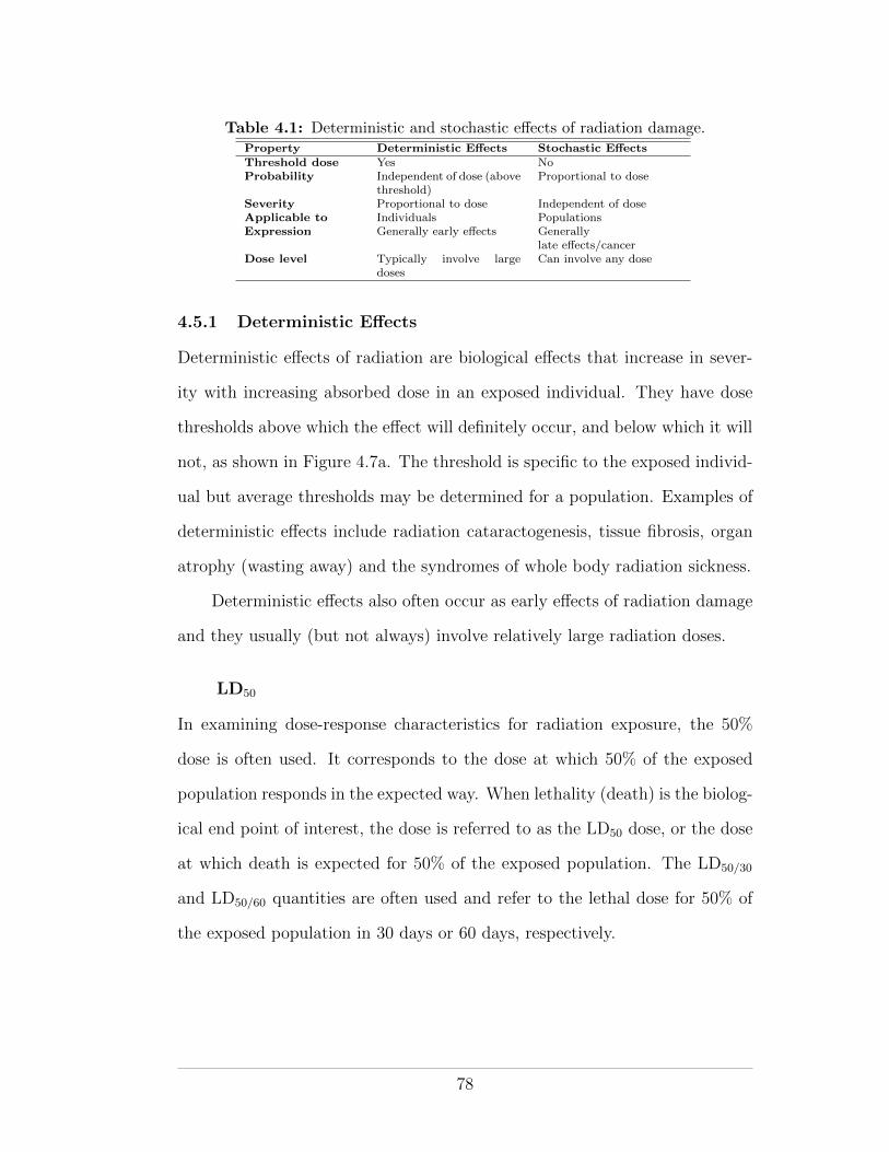
Table 4.1: Deterministic and stochastic e↵ects of radiation damage.Property Deterministic E↵ects Stochastic E↵ectsThreshold dose Yes NoProbability Independent of dose (above
threshold)Proportional to dose
Severity Proportional to dose Independent of doseApplicable to Individuals PopulationsExpression Generally early e↵ects Generally
late e↵ects/cancerDose level Typically involve large
dosesCan involve any dose
4.5.1 Deterministic E↵ects
Deterministic e↵ects of radiation are biological e↵ects that increase in sever-
ity with increasing absorbed dose in an exposed individual. They have dose
thresholds above which the e↵ect will definitely occur, and below which it will
not, as shown in Figure 4.7a. The threshold is specific to the exposed individ-
ual but average thresholds may be determined for a population. Examples of
deterministic e↵ects include radiation cataractogenesis, tissue fibrosis, organ
atrophy (wasting away) and the syndromes of whole body radiation sickness.
Deterministic e↵ects also often occur as early e↵ects of radiation damage
and they usually (but not always) involve relatively large radiation doses.
LD50
In examining dose-response characteristics for radiation exposure, the 50%
dose is often used. It corresponds to the dose at which 50% of the exposed
population responds in the expected way. When lethality (death) is the biolog-
ical end point of interest, the dose is referred to as the LD50 dose, or the dose
at which death is expected for 50% of the exposed population. The LD50/30
and LD50/60 quantities are often used and refer to the lethal dose for 50% of
the exposed population in 30 days or 60 days, respectively.
78
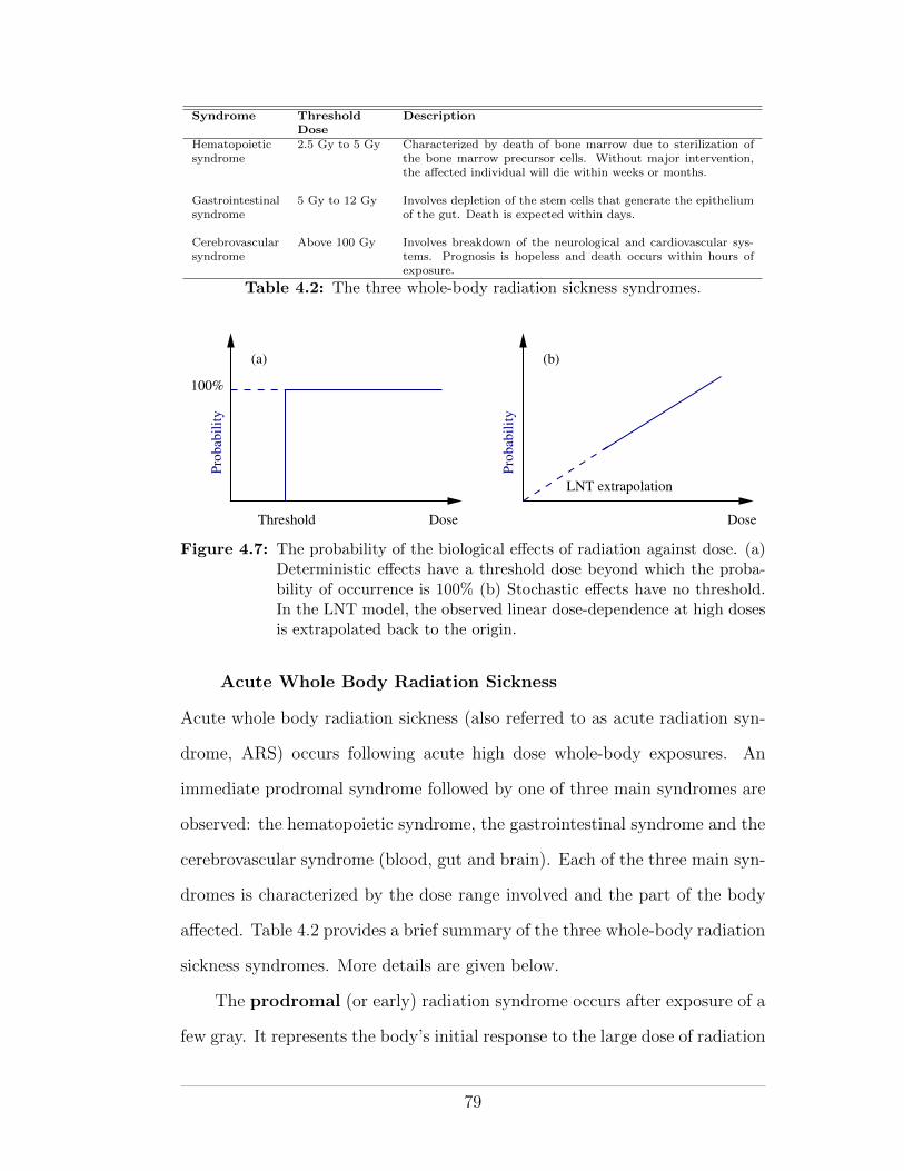
Syndrome ThresholdDose
Description
Hematopoieticsyndrome
2.5 Gy to 5 Gy Characterized by death of bone marrow due to sterilization ofthe bone marrow precursor cells. Without major intervention,the a↵ected individual will die within weeks or months.
Gastrointestinalsyndrome
5 Gy to 12 Gy Involves depletion of the stem cells that generate the epitheliumof the gut. Death is expected within days.
Cerebrovascularsyndrome
Above 100 Gy Involves breakdown of the neurological and cardiovascular sys-tems. Prognosis is hopeless and death occurs within hours ofexposure.
Table 4.2: The three whole-body radiation sickness syndromes.
Threshold
(a)
100%
Dose Dose
LNT extrapolation
Pro
bab
ilit
y
Pro
bab
ilit
y
(b)
Figure 4.7: The probability of the biological e↵ects of radiation against dose. (a)Deterministic e↵ects have a threshold dose beyond which the proba-bility of occurrence is 100% (b) Stochastic e↵ects have no threshold.In the LNT model, the observed linear dose-dependence at high dosesis extrapolated back to the origin.
Acute Whole Body Radiation Sickness
Acute whole body radiation sickness (also referred to as acute radiation syn-
drome, ARS) occurs following acute high dose whole-body exposures. An
immediate prodromal syndrome followed by one of three main syndromes are
observed: the hematopoietic syndrome, the gastrointestinal syndrome and the
cerebrovascular syndrome (blood, gut and brain). Each of the three main syn-
dromes is characterized by the dose range involved and the part of the body
a↵ected. Table 4.2 provides a brief summary of the three whole-body radiation
sickness syndromes. More details are given below.
The prodromal (or early) radiation syndrome occurs after exposure of a
few gray. It represents the body’s initial response to the large dose of radiation
79
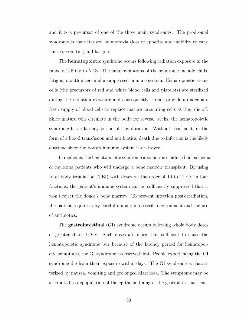
and it is a precursor of one of the three main syndromes. The prodromal
syndrome is characterized by anorexia (loss of appetite and inability to eat),
nausea, vomiting and fatigue.
The hematopoietic syndrome occurs following radiation exposure in the
range of 2.5 Gy to 5 Gy. The main symptoms of the syndrome include chills,
fatigue, mouth ulcers and a suppressed immune system. Hematopoietic stems
cells (the precursors of red and white blood cells and platelets) are sterilized
during the radiation exposure and consequently cannot provide an adequate
fresh supply of blood cells to replace mature circulating cells as they die o↵.
Since mature cells circulate in the body for several weeks, the hematopoietic
syndrome has a latency period of this duration. Without treatment, in the
form of a blood transfusion and antibiotics, death due to infection is the likely
outcome since the body’s immune system is destroyed.
In medicine, the hematopoietic syndrome is sometimes induced in leukaemia
or myleoma patients who will undergo a bone marrow transplant. By using
total body irradiation (TBI) with doses on the order of 10 to 12 Gy in four
fractions, the patient’s immune system can be su�ciently suppressed that it
won’t reject the donor’s bone marrow. To prevent infection post-irradiation,
the patient requires very careful nursing in a sterile environment and the use
of antibiotics.
The gastrointestinal (GI) syndrome occurs following whole body doses
of greater than 10 Gy. Such doses are more than su�cient to cause the
hematopoietic syndrome but because of the latency period for hematopoi-
etic symptoms, the GI syndrome is observed first. People experiencing the GI
syndrome die from their exposure within days. The GI syndrome is charac-
terized by nausea, vomiting and prolonged diarrhoea. The symptoms may be
attributed to depopulation of the epithelial lining of the gastrointestinal tract
80
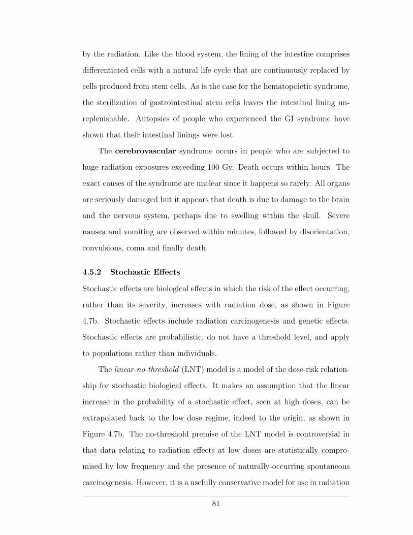
by the radiation. Like the blood system, the lining of the intestine comprises
di↵erentiated cells with a natural life cycle that are continuously replaced by
cells produced from stem cells. As is the case for the hematopoietic syndrome,
the sterilization of gastrointestinal stem cells leaves the intestinal lining un-
replenishable. Autopsies of people who experienced the GI syndrome have
shown that their intestinal linings were lost.
The cerebrovascular syndrome occurs in people who are subjected to
huge radiation exposures exceeding 100 Gy. Death occurs within hours. The
exact causes of the syndrome are unclear since it happens so rarely. All organs
are seriously damaged but it appears that death is due to damage to the brain
and the nervous system, perhaps due to swelling within the skull. Severe
nausea and vomiting are observed within minutes, followed by disorientation,
convulsions, coma and finally death.
4.5.2 Stochastic E↵ects
Stochastic e↵ects are biological e↵ects in which the risk of the e↵ect occurring,
rather than its severity, increases with radiation dose, as shown in Figure
4.7b. Stochastic e↵ects include radiation carcinogenesis and genetic e↵ects.
Stochastic e↵ects are probabilistic, do not have a threshold level, and apply
to populations rather than individuals.
The linear-no-threshold (LNT) model is a model of the dose-risk relation-
ship for stochastic biological e↵ects. It makes an assumption that the linear
increase in the probability of a stochastic e↵ect, seen at high doses, can be
extrapolated back to the low dose regime, indeed to the origin, as shown in
Figure 4.7b. The no-threshold premise of the LNT model is controversial in
that data relating to radiation e↵ects at low doses are statistically compro-
mised by low frequency and the presence of naturally-occurring spontaneous
carcinogenesis. However, it is a usefully conservative model for use in radiation
81
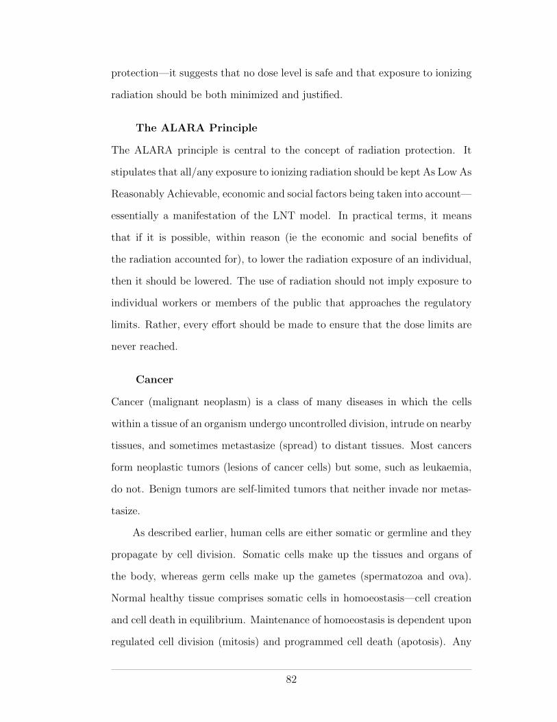
protection—it suggests that no dose level is safe and that exposure to ionizing
radiation should be both minimized and justified.
The ALARA Principle
The ALARA principle is central to the concept of radiation protection. It
stipulates that all/any exposure to ionizing radiation should be kept As Low As
Reasonably Achievable, economic and social factors being taken into account—
essentially a manifestation of the LNT model. In practical terms, it means
that if it is possible, within reason (ie the economic and social benefits of
the radiation accounted for), to lower the radiation exposure of an individual,
then it should be lowered. The use of radiation should not imply exposure to
individual workers or members of the public that approaches the regulatory
limits. Rather, every e↵ort should be made to ensure that the dose limits are
never reached.
Cancer
Cancer (malignant neoplasm) is a class of many diseases in which the cells
within a tissue of an organism undergo uncontrolled division, intrude on nearby
tissues, and sometimes metastasize (spread) to distant tissues. Most cancers
form neoplastic tumors (lesions of cancer cells) but some, such as leukaemia,
do not. Benign tumors are self-limited tumors that neither invade nor metas-
tasize.
As described earlier, human cells are either somatic or germline and they
propagate by cell division. Somatic cells make up the tissues and organs of
the body, whereas germ cells make up the gametes (spermatozoa and ova).
Normal healthy tissue comprises somatic cells in homoeostasis—cell creation
and cell death in equilibrium. Maintenance of homoeostasis is dependent upon
regulated cell division (mitosis) and programmed cell death (apotosis). Any
82
interruption in the regulation process may result in malignant progression from
homoeostasis to metastasis and thus the development of cancer. Three groups
of genes, proto-oncogenes, tumor-suppressor genes and DNA stability genes,
regulate the division and death of somatic cells.
It is at the DNA-level that carcinogenesis manifests itself: DNA damage
within the three groups of control genes may permit uncontrolled growth and
cellular immortality. Carcinogenesis may occur spontaneously through ran-
dom errors in DNA replication or may result from exposure to carcinogenic
agents such as chemical mutagens, ionizing radiation, UV and viruses.
Cancer may a↵ect people (and animals) of all ages, although the risk for
most types of cancer increases with age. It is estimated (Canadian Cancer
Society, 2009) that 40% of Canadian women and 45% of Canadian men will
develop some form of cancer during their lifetime. According to the Canadian
Cancer Society, 75 300 deaths due to cancer were expected in Canada during
2009. Indeed, the current cancer incidence in developed countries is about
5 000 new cancers per one million population, with the rate steadily increasing
by some 3% per year.
4.5.3 E↵ects of In-utero Irradiation
The developing embryo is highly sensitive to ionizing radiation due to exten-
sive cell division and rapid growth. Gestation may be divided into three main
stages: pre-implantation (up to 9 days following conception), major organo-
genesis (2nd to 8th week after conception) and fetal growth (end of major
organogenesis until term). Each stage is characterized by a di↵erent response
to radiation.
At the pre-implantation stage, the conceptus, which is still a small num-
ber of undi↵erentiated cells, is generally a↵ected in an all-or-nothing manner.
Either the radiation causes fatal damage, or the cells survive. During major
83
organogenesis, cellular di↵erentiation and the formation of tissues and organs
occurs. Each organ and tissue is most sensitive at the peak of its di↵erentia-
tion. The CNS appears to be particularly sensitive during major organogenesis
and microcephaly was observed in the children born by Hiroshima survivors
who were exposed at this stage. The final stage of development, fetal growth,
appears to be the least sensitive to radiation, although behavioural alterations
and reduced intelligence later in life have been observed. The biological e↵ects
of prenatal radiation were studied by the ICRP and reported in publication
90 (ICRP Publication 90, 2003).
84
CHAPTER 5Radiation Protection Organisations
As we have seen, radiation o↵ers great benefits to society but presents sig-
nificant health risks. It is an toxic agent undetectable to our senses, the
deterministic and stochastic consequences of which are delayed, such that our
repulsive reflexes cannot warn and protect us. To mitigate the, non-obvious,
risks, public health policy mandates maximum radiation dose limits for non-
background exposure. Two sets of limits are imposed; one set for members of
the public and another, less restrictive, set for people who are likely to become
exposed at work and who accept the higher risk posed by their occupation.
In this chapter we will review the organizations that recommend and set
dose limits for radiation exposure.
5.1 Historical Perspective
The science of radiation protection (ie health physics) grew in parallel to devel-
opments in diagnostic radiology and radiation therapy, following the discovery
of radiation by Rontgen in 1895. The earliest recorded biologic e↵ects of ra-
diation were reported within a year of Rontgen’s discovery and included skin
“burns”, epilation and eye irritation (Hall and Giaccia, 2006). In 1915, the
British Rontgen Society introduced the first formal proposals for radiation
protection. A little over a decade later, in 1928, the British proposals were
internationally adopted at the Second International Congress of Radiology in
Stockholm. At the same congress, the International X-Ray and Radium Pro-
tection Committee (IXRPC) was established. Following World War II, and
the renewed urgency for radiation protection precipitated by the nuclear arms
85
race, the IXRPC was reconstituted as two separate commissions: the Interna-
tional Commission on Radiological Protection (ICRP) and the International
Commission on Radiation Units and Measurements (ICRU), both of which
still operate.
The US equivalent of the IXRPC was the Advisory Committee on X-Ray
and Radium Protection, which operated from 1929 until the end of World War
II. In 1946, it was replaced by the National Council on Radiation Protection
and Measurements (NCRP), a non-governmental public service organization
with a congressional charter to provide recommendations regarding radiation
protection. NCRP reports form the basis of radiation protection policy within
the United States and are consulted internationally for their scientific value.
In Canada, the Atomic Energy Control Board (AECB) was established
under the Atomic Energy Control Act of 1946, with a charge to assist the
Canadian government in matters pertaining to radiation in regulation, mining
and research. In 2000, the Canadian Nuclear Safety Commission (CNSC)
replaced the AECB. The commission’s mandate is stipulated in the Nuclear
Safety and Control Act of 1997 and it serves to regulate the use of nuclear
energy and materials in Canada.
5.2 Modern Organizations for Radiation Protection
Today, numerous organizations are involved in matters pertaining to radiation
protection. Table 5.1 provides a list of the most important organizations with
a summary of the services they provide. All levels of organization are encoun-
tered; international, national, provincial/state, municipal and institutional.
86
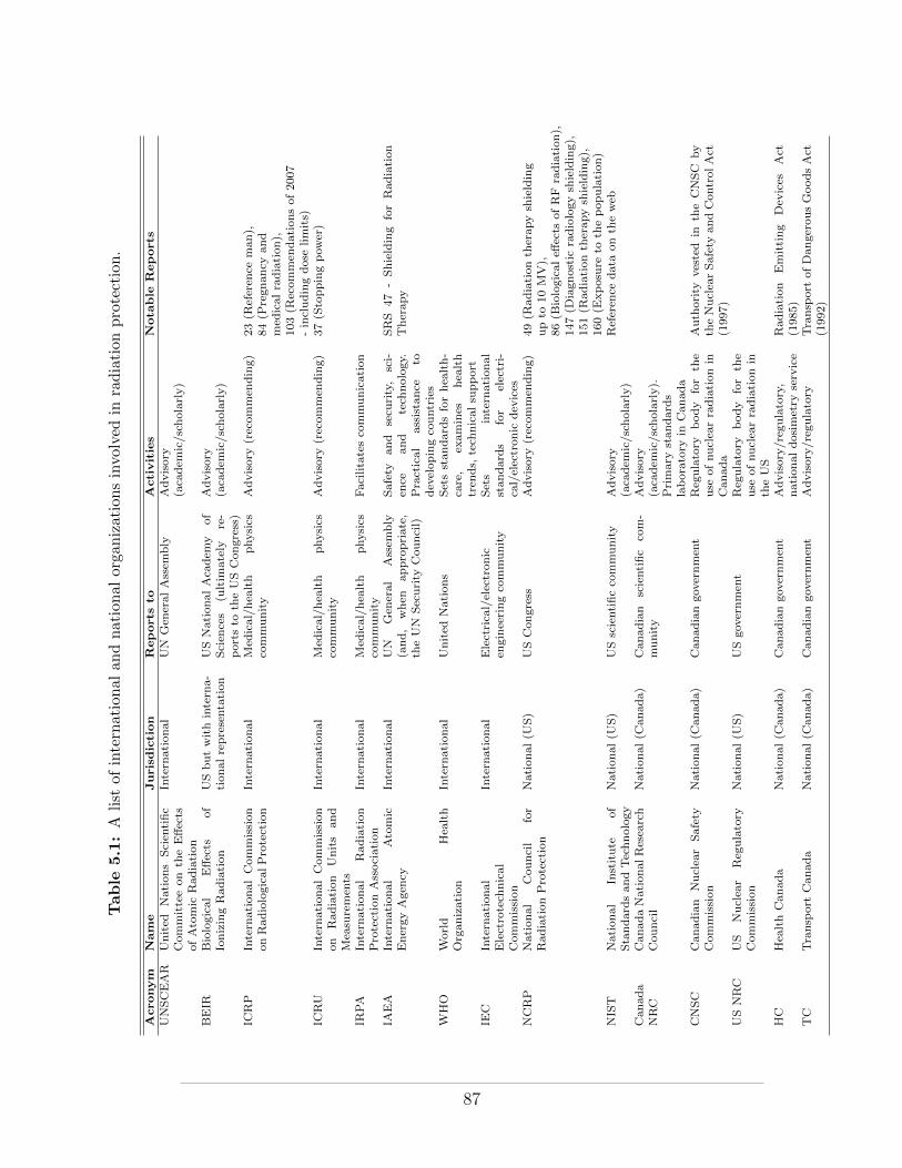
Table
5.1:A
list
ofinternational
andnational
orga
nizationsinvolved
inradiation
protection.
Acronym
Nam
eJurisdiction
Reports
toActivities
Nota
ble
Reports
UNSCEAR
United
Nations
Scien
tific
Committeeon
theE↵ects
ofAtomic
Radiation
Intern
ational
UN
Gen
eral
Assem
bly
Advisory
(aca
dem
ic/scholarly)
BEIR
Biological
E↵ects
of
IonizingRadiation
USbutwithintern
a-tionalrepresentation
USNational
Aca
dem
yof
Scien
ces
(ultim
ately
re-
ports
toth
eUSCongress)
Advisory
(aca
dem
ic/scholarly)
ICRP
Intern
ationalCommission
onRadiologicalProtection
Intern
ational
Med
ical/hea
lth
physics
community
Advisory(recom
men
ding)
23(R
eferen
ceman
),84(P
regnancy
and
med
icalradiation),
103(R
ecommen
dationsof2007
-includingdose
limits)
ICRU
Intern
ationalCom
mission
on
Radiation
Units
and
Mea
suremen
ts
Intern
ational
Med
ical/hea
lth
physics
community
Advisory(recom
men
ding)
37(S
toppingpow
er)
IRPA
Intern
ational
Radiation
ProtectionAssociation
Intern
ational
Med
ical/hea
lth
physics
community
Facilitatesco
mmunication
IAEA
Intern
ational
Atomic
EnergyAgen
cyIntern
ational
UN
Gen
eral
Assem
bly
(and,
when
appropriate,
theUN
Security
Council)
Safety
and
secu
rity,
sci-
ence
and
tech
nology.
Practical
assistance
todev
elopingco
untries
SRS
47
-Shielding
forRadiation
Therapy
WHO
World
Hea
lth
Organization
Intern
ational
United
Nations
Setsstandard
sforhea
lth-
care,
examines
hea
lth
tren
ds,
tech
nicalsu
pport
IEC
Intern
ational
Electrotech
nical
Commission
Intern
ational
Electrica
l/electronic
engineeringco
mmunity
Sets
intern
ational
standard
sfor
electri-
cal/electronic
dev
ices
NCRP
National
Cou
ncil
for
RadiationProtection
National
(US)
USCon
gress
Advisory(recom
men
ding)
49(R
adiation
therap
ysh
ielding
upto
10MV),
86(B
iologicale↵
ects
ofRF
radiation),
147(D
iagnostic
radiologysh
ielding),
151(R
adiationth
erapysh
ielding),
160(E
xposure
toth
epopulation)
NIST
National
Institute
ofStandard
sandTechnology
National
(US)
USscientificco
mmunity
Advisory
(aca
dem
ic/scholarly)
Referen
cedata
onth
eweb
Canada
NRC
CanadaNationalResea
rch
Council
National
(Can
ada)
Can
adian
scientific
com-
munity
Advisory
(aca
dem
ic/scholarly).
Primary
standard
slaboratory
inCanada
CNSC
Canadian
Nuclea
rSafety
Commission
National
(Can
ada)
Can
adiango
vernmen
tReg
ulatory
body
for
the
use
ofnuclea
rradiation
inCanada
Auth
ority
vested
inth
eCNSC
by
theNuclea
rSafety
andCon
trolAct
(1997)
USNRC
US
Nuclea
rReg
ulatory
Commission
National
(US)
USgo
vernmen
tReg
ulatory
body
for
the
use
ofnuclea
rradiation
inth
eUS
HC
Hea
lthCan
ada
National
(Can
ada)
Can
adiango
vernmen
tAdvisory/reg
ulatory,
nationaldosimetry
service
Radiation
Emitting
Dev
ices
Act
(1985)
TC
Transp
ort
Canada
National(C
anada)
Canadiangov
ernmen
tAdvisory/regulatory
Transp
ort
ofDangerou
sGoodsAct
(1992)
87
5.2.1 International
Organizations interested in radiation protection at the international level are
advisory in statute. They may provide recommendations based on their sci-
entific findings (for example, the ICRP and the IAEA) or they may simply
present scholarly reports of their scientific investigations (for example, UN-
SCEAR). A number of international organizations (for example the IAEA, the
WHO and the IRPA) also provide practical scientific support for member coun-
tries, particularly for developing countries that do not have well-established
national radiation protection organizations of their own.
5.2.2 National/Provincial
At the national level, radiation protection organizations may provide non-
binding advice and/or scientific analysis or they may draft nationally binding
regulations. Examples include the CNSC, Health Canada’s Radiation Protec-
tion Bureau and Transport Canada in Canada and the NCRP and NRC in
the United States. Provincial/state organizations typically draft binding reg-
ulations that have jurisdiction over areas of radiation protection not covered
by national regulations.
In Canada, radioactive materials (including all nuclear substances, nu-
clear medicine and high-energy radiation therapy, which involves induced-
radioactivity) are regulated at the federal level by the CNSC, while x-ray pro-
duction (diagnostic radiology) is the responsibility of the provinces. In Quebec,
regulations pertaining to the use of radiation-emitting devices were drawn up
by the Service de Radioprotection of the Ministere de l’Environnement and
are stipulated in the Quebec civil code.
88
5.2.3 Municipal/Institutional
At the municipal and institutional levels, radiation protection is generally
a matter of solicitation and involves radiation safety committees established
for the purpose of coordinating radiation protection programs in accordance
with provincial/national regulations. For example, two radiation safety o�cers
(physicists) are employed at the McGill University Health Centre, one with
responsibility over radiation safety in the department of Radiation Oncology
and the other with general responsibility for radiation safety throughout the
hospital.
89
CHAPTER 6Radiation Protection Regulations
In Canada, the CNSC regulates radiation dose limits and the production and
use of radioactive materials using the authority vested in it by the “Nuclear
Safety and Control Act” (NSCA) of 1997. The import/export and sale of
radiation-emitting devices (including diagnostic x-ray equipment and x-ray
imaging machines for airport security) are regulated by Health Canada under
the “Radiation Emitting Devices Act” (RED Act) of 1985. The transport
of radioactive material is regulated by Transport Canada according to the
“Transport of Dangerous Goods Act” (TDG Act) of 1992.
6.0.1 The Nuclear Safety and Control Act
The NSCA was approved by the Canadian Parliament in 1997 and came into
force in May 2000. It replaced the Atomic Energy Control Act of 1946 and
replaced the Atomic Energy Control Board with the, more powerful, CNSC, as
the sole authority to regulate the production and use of radioactive materials
in Canada. CNSC jurisdiction covers the following uses of radiation:
• Power reactors
• Non-power reactors
• Nuclear research and test establishments
• Uranium mines and mills
• Processing and fuel fabrication facilities
• Heavy water production plants
• Nuclear substance processing facilities
• Particle accelerators
90
• Waste management facilities
• Packaging and transportation of nuclear substances
• Nuclear substances and radiation devices
• Lands under evaluation
• Irradiators
• Imports and exports of nuclear items
• Exports of nuclear-related dual-use items
• Dosimetry service providers
The NSCA provides the legal definition of a “nuclear energy worker” (NEW)
in Canada. A NEW is defined as
A person who is required, in the course of the person’s business or occupation
in connection with a nuclear substance or nuclear facility, to perform duties
in such circumstances that there is a reasonable probability that the person
may receive a dose of radiation that is greater than the prescribed limit for
the general public.
The NSCA also provides the legal definitions for nuclear facility, nuclear sub-
stance, prescribed equipment (ie equipment that is controlled by the act) and
radiation, amongst other terms.
The main purpose of the NSCA is to provide a legal basis and framework
of operation for the CNSC, which was established under the act. The makeup
of the CNSC and the powers vested in it are detailed within the act. Notable
powers of the commission include the power to act as a court of record, the
power to establish classes of licences for the use of radioactive materials within
Canada, the power of inspection and the power to search without warrant in
order to ensure compliance with the NSCA. The CNSC is also provided with
the power to regulate the use of radioactive materials, the use of prescribed
91
equipment, the disclosure of prescribed information, the setting of radiation
dose limits and the protection of nuclear energy workers, amongst other details.
6.0.2 CNSC Regulations of Interest
In this section we will examine several of the CNSC regulations and highlight
certain points of interest relevant to this course in Health Physics. The regu-
lations and the NSCA itself are quite readable and may be downloaded from
the CNSC website (www.cnsc-ccsn.gc.ca).
Radiation Protection Regulations
The radiation protection regulations apply generally to all licensed uses of
radiation covered by the NSCA, except to the medical administration of ra-
dioactive substances to a patient or to a biomedical research volunteer (for
which there is a sole requirement to advise the person, to whom the radioac-
tive substance has been administered, of the methods by which he/she may
reduce the exposure to others upon leaving the hospital/clinic). Some high-
lights of the radiation protection regulations include:
• The requirement to put in place a radiation protection program when
using CNSC-licensed substances/equipment.
• The requirement to keep e↵ective and equivalent doses ALARA, social
and economic factors being taken into account.
• The requirement to monitor and record e↵ective and equivalent doses.
• The definition of an “action level”, as the level of radiation dose that, if
reached, may indicate loss of control of the radiation protection program.
– the action level is set, as appropriate, in each individual license
• The requirement to undertake the following actions should an action
level be reached:
– investigate the cause
92
– fix the problem
– notify the CNSC within the time period specified in the licence
• The setting of dose limits from man-made radiation in Canada.
– the Canadian limits on e↵ective dose and equivalent doses, as set
by the CNSC, are listed in table 6.1
• The requirement to inform nuclear energy workers, in writing, that they
are nuclear energy workers, explain to them the associated risks and dose
limits and to provide them with their radiation dose levels.
• The requirement to obtain from nuclear energy workers written acknowl-
edgement (i.e., signature) that he/she has received the information.
• The requirement to inform each female nuclear energy worker, in writing,
of the rights and obligations of pregnant nuclear energy workers.
– the licensee must make any accommodation, that does not hurt
his/her business, to ensure that the pregnant nuclear energy worker
does not exceed the dose limits set for pregnant nuclear energy
workers.
– a pregnant nuclear energy worker is required to inform the licensee,
in writing, immediately when she becomes aware that she is preg-
nant
• The requirement to use a licensed dosimetry service (e.g, the National
Dosimetry Service of Health Canada) to measure and monitor the doses
of radiation recived by and committed to nuclear energy workers who
have a reasonable probability of recieving an e↵ective dose greater than
5 mSv in a one-year dosimetry period.
– The licensed dosimetry service is in turn required to file all mea-
sured and monitored doses with the National Dose Registry that is
maintained by Health Canada.
93
• During an emergency, the dose limits for non-pregnant nuclear energy
workers, are increased to 500 mSv e↵ective dose and 5 000 mSv equiva-
lent dose (essentially a 10-fold increase on the non-emergency limits).
– Since the limits for pregnant nuclear energy workers are not in-
creased during an emergency, it is common practisee to remove
pregnant nuclear energy workers from work situations in which
emergencies may occur. For example, at the Montreal General
Hospital pregnant nuclear energy workers do not work with nu-
clear substances (Colbalt teletherapy or brachytherapy), for which
emergency situations may present the possibility of increased dose.
An emergency situatioin with a linac, on the otherhand, should not
present the risk of increased dose as a linac can simply be turned
o↵ in an emergency.
• A person can exceed all dose limits when acting voluntarily to save or
protect human life.
• When a dose limit is exceeded specific actions are required. These in-
clude:
– Immediately notify the person and the CNSC
– Require the person to leave any work that may add to the dose
– Conduct an investigation to determine the magnitude of the dose
and to establish the cause of the exposure
– Identify and take any action required to prevent a similar incident
from occuring again
– Report to the CNSC within 21 days the results or progress of the
investigation
• The person who has exceeded the dose limit may not return to work
until authorized by the CNSC. Authorization may include restrictions.
94
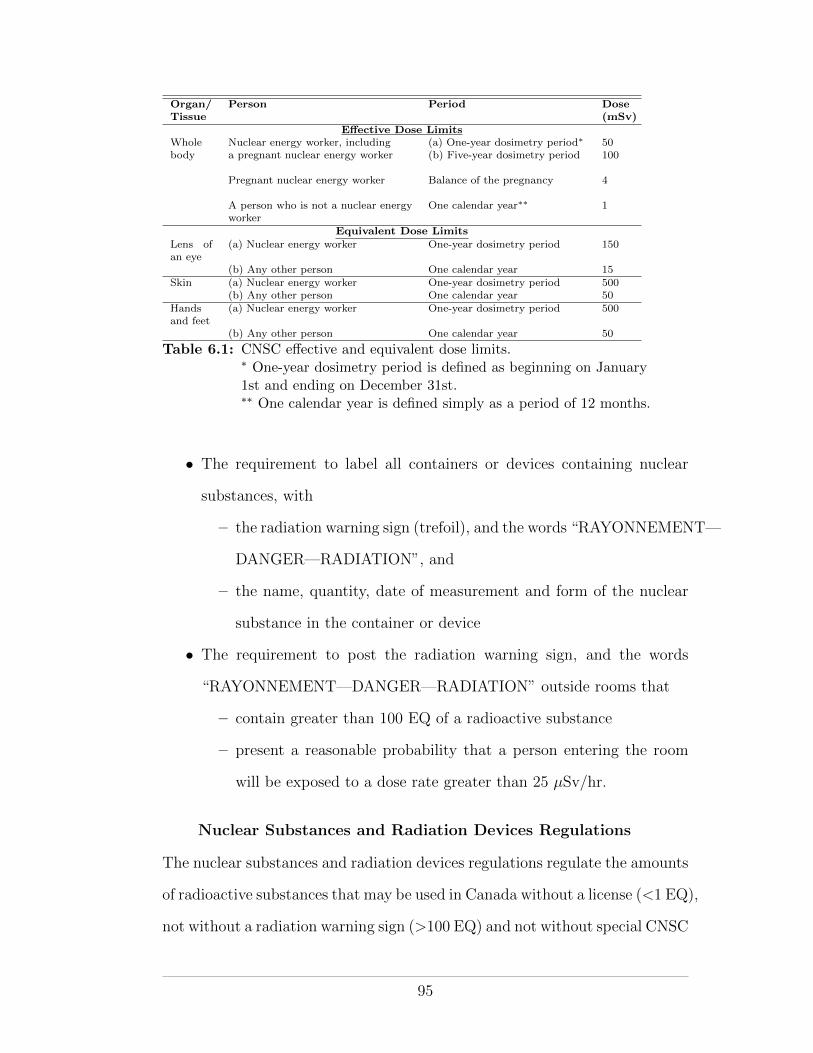
Organ/Tissue
Person Period Dose(mSv)
E↵ective Dose LimitsWhole Nuclear energy worker, including (a) One-year dosimetry period⇤ 50body a pregnant nuclear energy worker (b) Five-year dosimetry period 100
Pregnant nuclear energy worker Balance of the pregnancy 4
A person who is not a nuclear energyworker
One calendar year⇤⇤ 1
Equivalent Dose Limits
Lens ofan eye
(a) Nuclear energy worker One-year dosimetry period 150
(b) Any other person One calendar year 15Skin (a) Nuclear energy worker One-year dosimetry period 500
(b) Any other person One calendar year 50Handsand feet
(a) Nuclear energy worker One-year dosimetry period 500
(b) Any other person One calendar year 50
Table 6.1: CNSC e↵ective and equivalent dose limits.⇤ One-year dosimetry period is defined as beginning on January1st and ending on December 31st.⇤⇤ One calendar year is defined simply as a period of 12 months.
• The requirement to label all containers or devices containing nuclear
substances, with
– the radiation warning sign (trefoil), and the words “RAYONNEMENT—
DANGER—RADIATION”, and
– the name, quantity, date of measurement and form of the nuclear
substance in the container or device
• The requirement to post the radiation warning sign, and the words
“RAYONNEMENT—DANGER—RADIATION” outside rooms that
– contain greater than 100 EQ of a radioactive substance
– present a reasonable probability that a person entering the room
will be exposed to a dose rate greater than 25 µSv/hr.
Nuclear Substances and Radiation Devices Regulations
The nuclear substances and radiation devices regulations regulate the amounts
of radioactive substances that may be used in Canada without a license (<1 EQ),
not without a radiation warning sign (>100 EQ) and not without special CNSC
95
permission (>10 000 EQ). Special exemptions are made for smoke detectors,
tritium safety signs, and check sources (such as those used with survey meters).
These regulations also mandate leak tests, to be performed on sealed
sources containing 50 MBq or more. A leak test should be performed imme-
diately before using the sealed source, if it has been in storage for the last
12 months, or every 24 months if the source is in long-term storage. Fur-
thermore, leak tests should be performed immediately if a source is damaged.
Sealed sources contained within radiation devices (for example, a Cobalt-60
teletherapy device) must be leak-tested every 12 months.
Class I Nuclear Facilities Regulations
Class I facilities are sub-categorized as class IA and Class IB facilities. Class
IA facilities refer to facilities that contain nuclear reactors. Class IB facilities
are facilities that process uranium, thorium or plutonium or they are facilities
that are not covered under the definition of Class II facilities, as defined in the
Class II regulations.
Interesting highlights of the class I nuclear facilities regulations include:
• The definition of an “exclusion zone” as a parcel of land within or sur-
rounding a nuclear facility on which there is no permanent dwelling and
over which a licensee has the legal authority to exercise control.
• The requirement that the licensee undertake measures to prevent acts of
sabotage or attempted sabotage (ie nuclear terrorism).
Class II Nuclear Facilities and Prescribed Equipment Regula-tions
Class II nuclear facilities and prescribed equipment regulations are of most
interest to medical physicists. A class II nuclear facility is defined as a facility
96
that includes Class II prescribed equipment. Class II prescribed equipment is
defined to cover many types of radiation-emitting devices including
• Irradiators with more than 1015 Bq of nuclear substance
• Irradiators that require external shielding and which can deliver dose
rates of more than 1 cGy/min at 1 m.
• A radioactive source teletherapy machine.
• Particle accelerators up to 50 MeV if the particles have a mass less than
or equal to 4 atomic mass units.
• Particle accelerators up to 15 MeV if the particles have a mass greater
than 4 atomic mass units.
• A brachytherapy remote afterloader.
An exact list of class II prescribed equipment certified by the CNSC for
use in Canada, as of September 2010, can be found on the CNSC’s website.
After defining the types of equipment that fall under the class II category,
some details regarding license applications for class II facilities are outlined.
Class II facilities are required to apply for a license to construct before con-
struction of the facility begins, a license to operate before the equipment can
be used at the facility and a license to decommission before the equipment can
be un-installed. The equipment itself must also be certified (ie approved by
the CNSC) before it may be used.
The class II nuclear facilities and prescribed equipment regulations pro-
vide detailed requirements pertaining to radiation protection at class II facil-
ities. The radiation protection requirements mandate the following for rooms
containing class II prescribed equipment:
• A door interlock that prevents the equipment from being used while the
door is open.
97
• Last-person out safety check buttons that must be pressed, in the correct
sequence, inside the room and then outside the room, in order to operate
the equipment.
• A mechanism to ensure that no person can be locked inside the room.
• A system to allow the operator to view the interior of the room during
operation of the equipment.
• A visible display (ie warning light) outside of a room that indicates the
irradiation state of the equipment contained within it.
• An area radiation monitoring system if the room contains prescribed
equipment other than a particle accelerator.
– the reason for area monitoring in rooms not containing particle ac-
celerators is to provide a visual warning, independent of the device,
that the source is in the unshielded position. Particle accelerators,
since they require electricity to function, can be reliably stopped
by simply removing the power supply.
• Emergency stop buttons at various locations inside and outside the room.
• Posting of emergency contact details at the entrance to the facility.
Radiation Safety O�cers (RSOs) are mandated by the class II nuclear
facilities and prescribed equipment regulations. An RSO must be certified by
the CNSC after having undergone a CNSC examination.
Some special regulations pertaining to brachytherapy remote afterloaders
are specified:
• All patients who undergo brachytherapy treatments must be surveyed
with a survey meter before they are released.
• A room containing a brachytherapy remote afterloader should contain a
shielded storage container and remote handling tools to recover radioac-
tive sources in an emergency.
98
Radiation survey meters must be made available to each worker in a class
II nuclear facility. The survey meter must meet the following requirements:
1. Have been calibrated within the last 12 months.
2. Must be cable of measuring the x-ray, gamma-ray and, if applicable,
neutron radiation from the equipment.
3. Must have a battery power-level indicator.
Class II prescribed equipment cannot be used on a person (ie patient)
unless directed by a qualified medical practitioner.
Various records regarding the details of the class II prescribed equipment
and its usage must be retained. Such records include the daily output of the
machine and details of worker training. All records should be kept for three
years after the expiry date of the class II license.
6.0.3 Radiation Emitting Devices
The import, export, leasing, buying and selling of radiation-emitting devices
for certain medical, industrial and consumer applications are controlled by
the Radiation Emitting Devices (RED) Act of 1985 and associated regula-
tions drawn up by Health Canada. The RED regulations to not apply to
devices that are designed for the production of nuclear energy (such devices
are regulated by the CNSC under the NSCA). They also do not regulate the
use of radiation-emitting devices, once purchased. They do, however, cover the
purchase of x-ray tubes (for diagnostic radiology), x-ray machines and linear
accelerators (for radiation therapy) as well as UV tanning equipment. Manu-
facturers intending to sell radiation emitting devices within Canada must first
obtain Health Canada approval in order to do so.
99
6.0.4 Transport Regulations for Radioactive Material and Devices
The packaging and transport of radioactive substances within Canada is regu-
lated by the CNSC in cooperation with Transport Canada. The transportation
of dangerous goods, in general, is regulated by the Transportation of Danger-
ous Goods (TDG) Act of 1992 and associated regulations, while the regulations
governing the transport of radioactive material, in particular, is codified in the
CNSC’s “Packaging and Transport of Nuclear Substances Regulations”.
The TDG Act stipulates certain requirements for the labelling and trans-
port of a package containing dangerous goods. Since dangerous goods are
frequently shipped internationally, Canada adheres to the recommendations
drawn up by the United Nations Sub-Committee of Experts on the Transport
of Dangerous Goods . Specific international recommendations for the trans-
port of radioactive substances are found in the IAEA Safety Standards reports
pertaining to transportation.
UN recommendations specify a coloured diamond-shaped label for the
packaging of dangerous goods and nine classes of goods. The nine classes are
listed in table 6.2. Radioactive materials fall under class 7. Four categories
of class 7 goods are defined, each with a di↵erent placard. Categories I, II
and III include radioactive materials with increasing activities and transport
indices. The fourth category is for fissile material. Class 7 radioactive goods
must display a label that specifies the following information:
• the name(s) or symbol(s) of the nuclear material,
• the activity of the nuclear material, and
• the transport index of the nuclear material.
The category into which the radioactive goods fall, and hence the labelling
of the package used to transport them, is determined by the dose rate at the
external surface of the package and the transport index of the package (ie dose
100
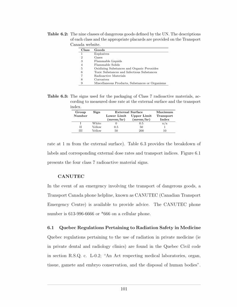
Table 6.2: The nine classes of dangerous goods defined by the UN. The descriptionsof each class and the appropriate placards are provided on the TransportCanada website.
Class Goods1 Explosives2 Gases3 Flammable Liquids4 Flammable Solids5 Oxidizing Substances and Organic Peroxides6 Toxic Substances and Infectious Substances7 Radioactive Materials8 Corrosives9 Miscellaneous Products, Substances or Organisms
Table 6.3: The signs used for the packaging of Class 7 radioactive materials, ac-cording to measured dose rate at the external surface and the transportindex.
Group Sign External Surface MaximumNumber Lower Limit Upper Limit Transport
(mrem/hr) (mrem/hr) IndexI White 0 0.5 n/aII Yellow 0.5 50 1III Yellow 50 200 10
rate at 1 m from the external surface). Table 6.3 provides the breakdown of
labels and corresponding external dose rates and transport indices. Figure 6.1
presents the four class 7 radioactive material signs.
CANUTEC
In the event of an emergency involving the transport of dangerous goods, a
Transport Canada phone helpline, known as CANUTEC (Canadian Transport
Emergency Centre) is available to provide advice. The CANUTEC phone
number is 613-996-6666 or *666 on a cellular phone.
6.1 Quebec Regulations Pertaining to Radiation Safety in Medicine
Quebec regulations pertaining to the use of radiation in private medicine (ie
in private dental and radiology clinics) are found in the Quebec Civil code
in section R.S.Q. c. L-0.2; “An Act respecting medical laboratories, organ,
tissue, gamete and embryo conservation, and the disposal of human bodies”.
101
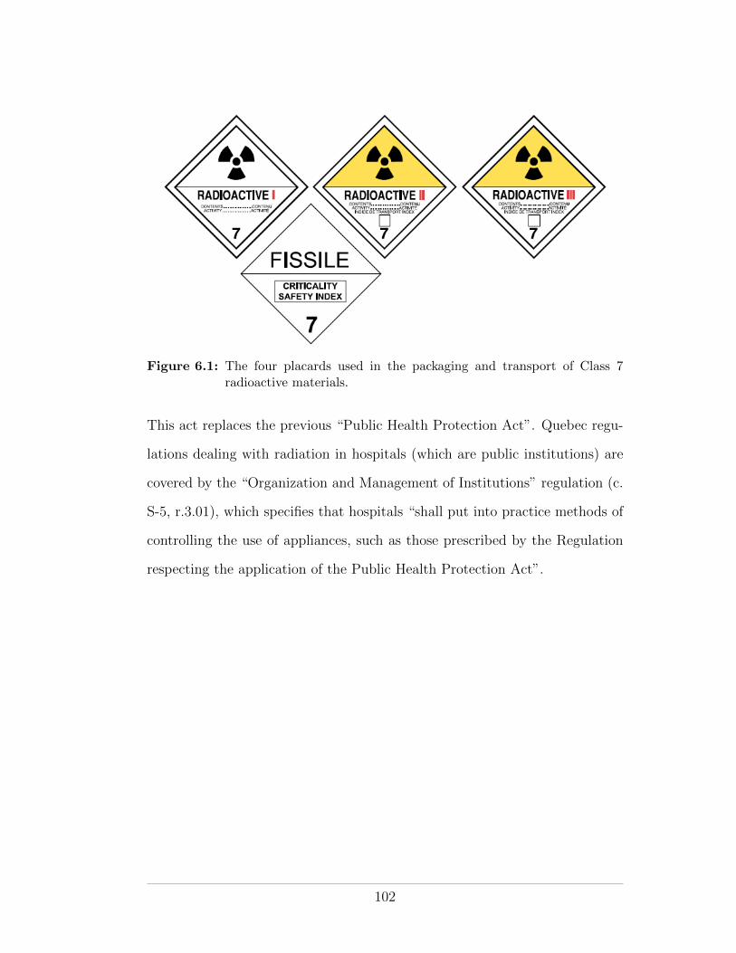
Figure 6.1: The four placards used in the packaging and transport of Class 7radioactive materials.
This act replaces the previous “Public Health Protection Act”. Quebec regu-
lations dealing with radiation in hospitals (which are public institutions) are
covered by the “Organization and Management of Institutions” regulation (c.
S-5, r.3.01), which specifies that hospitals “shall put into practice methods of
controlling the use of appliances, such as those prescribed by the Regulation
respecting the application of the Public Health Protection Act”.
102
CHAPTER 7Radiation Protection In Practice
At this stage we should have a good understanding of what radiation is, how
it can a↵ect our health and how we can detect and quantify it. We have seen
that there are legal restrictions on the use and handling of radioactive sub-
stances and radiation emitting devices - imposed by the federal and provincial
governments for our safety. We have also seen that there are scientific and
regulatory organizations available to guide us in our radiation protection ef-
forts. With radiation protection theory examined, it is now time to focus on
how we can apply radiation protection principles to practical situations where
radiation is encountered.
According to the ICRP (reports 103, 60, etc), the three principles of ra-
diation protection - justification, optimization and application of dose limits
- apply to all situations in which radiation is used. Similarly the three tenets
of physical radiation protection - distance, time, and shielding - apply to all
instances of actual radiation exposure. In this chapter we will use these two
triads of radiation protection together with practical recommendations from
various guidance documents and federal and provincial regulations to enumer-
ate the main components of a practical radiation protection program.
7.1 Context
In approaching the task of implementing a radiation protection program it is
important to first put the planned radiation exposure situation into context.
Three questions help contextualize the exposure situation:
1. What type of exposure situation is expected?
103
2. What category of individuals will or might be exposed?
3. Which regulations apply?
7.1.1 Type of Exposure Situation
According to the ICRP, three main types of exposure situation can be envis-
aged; planned, emergency and existing exposure situations. Additionally, the
ICRP recommend that medical exposure, although it technically falls under
planned exposure, should be dealt with separately owing to the di↵erent radi-
ation protection considerations involved. The following definitions are taken
directly from ICRP report 103:
Planned exposure situations are situations involving the deliberate intro-
duction and operation of sources. Planned exposure situations may give
rise both to exposures that are anticipated to occur (normal exposures)
and to exposures that are not anticipated to occur (potential exposures).
Emergency exposure situations are situations that may occur during the
operation of a planned situation, or from a malicious act, or from any
other unexpected situation, and require urgent action in order to avoid
or reduce undesirable consequences.
Existing exposure situations are exposure situations that already exist when
a decision on control has to be taken, including prolonged exposure sit-
uations after emergencies.
Medical exposure situations are exposure situations that are planned in
advance for the purpose of diagnosis, intervention, therapy or biomedical
research.
104
7.1.2 Category of Exposed Individuals
The ICRP distinguish between three categories of exposed individuals—occupationally
exposed workers, members of the public and patients exposed for medical rea-
sons. While recognizing that workers might also be exposed to ionizing radi-
ation as members of the public or as patients, the commission recommends
against attempting to combine, for regulatory purposes, exposures from each
category.
Workers
A worker is defined by the ICRP as
any person who is employed, whether full time, part time, or tem-
porarily, by an employer and who has recognized rights and duties
in relation to occupational radiological protection.
Although no distinction is made between the sexes, special consideration is
recommended for female workers who are pregnant or nursing. Additional
radiation protection controls are must be considered in order to protect the
embryo/fetus.
Members of the Public
In ICRP report 103, a member of the public is defined as
as any individual who receives an exposure that is neither occupa-
tional nor medical.
In considering measures to protect members of the public the ICRP recom-
mend use of the concept of the Representative Person, who is representative of
the group of individuals in the population who are most exposed to background
radiation sources - both man-made and natural.
105
Patients
The ICRP define a patient as
an individual who receives an exposure associated with a diagnos-
tic, interventional, or therapeutic procedure.
Dose limits are not recommended for patients but the principles of justification
and optimization of dose still apply, see section 7.2 below.
7.1.3 Regulatory Jurisdiction
As outlined in chapter 6, in Canada all matters pertaining to the control
of exposure due to nuclear substances (ie the control of practices involving
radioactive materials and radiation devices that may induce activation) are
regulated on behalf the federal government by the CNSC. Jurisdiction for
the control of exposure due to radiation-emitting devices that do not induce
activation (eg medical and dental x-ray tubes, CT scanners and fluoroscopes)
are regulated by provincial governments. Any practice involving radiation
exposure and associated protection programs must adhere to the appropriate
federal and/or provincial regulations, as appropriate.
7.2 Applying the Three Main Principles of Radiation Protection
The three main principles of radiation protection as promulgated and refined
in numerous ICRP publications apply to all types of exposure situation and to
all categories of exposed individuals. Actual implementation of the principles
will depend on the exposure context (ie, exposure type and category of exposed
individuals).
7.2.1 The Principle of Justification
The principle of justification plays a pivotal role in the establishment of any
radiation protection program. Is the proposed exposure activity justified? Is
106
the radiation really needed? Is there another, safer, way of performing the
activity without the use of radiation? In their most recent recommendations
(ICRP Report 103) the ICRP present the principle of justification as follows:
The principle of justification: Any decision that alters the
radiation exposure situation should do more good than harm.
It is interesting that the ICRP use the word alter rather than increase. Essen-
tially they recognize that the consequences of a justification decision are not
confined solely to the use of the radiation. Rather, the activity as a whole,
of which the use of radiation may be just one part, needs to be considered
comprehensively.
Application of the principle of justification depends on whether the ac-
tivity involving radiation exposure is planned in advance, is unplanned or is
for medical purposes.
Planned Exposure. Introduction of a planned activity (ie a new ac-
tivity) should not proceed unless it o↵ers su�cient net positive benefit to the
individuals exposed or to society as a whole to o↵set the radiation detriment
it causes. The introduction of a planned exposure activity will only increase
the dose (and hence detriment) to the exposed population. As such, radiation
protection measures should be planned in advance and applied directly to the
source of the radiation from the outset.
Unplanned exposure. Action should not be taken to change an un-
planned exposure situation (ie an emergency or an existing exposure situation)
unless the action causes net positive benefit. It is recognized here that any
actions taken to avert future exposure may also have disadvantages in terms
of the resultant balance of good versus harm to society.
107
Medical exposure. The aim of medical exposure is to do more good
than harm to the patient (or to society as a whole through the exposure of
volunteers for biomedical research). As such, medical exposure should be
intrinsically justified, with due regard for the well-being of the medical sta↵
involved.
Unjustified Exposure. Some exposure situations are never justified.
Three categories of unjustified exposure are identified by the ICRP:
1. Exposure due to the deliberate addition of radioactive substances to food
and personal objects such as toys, clothing and jewellery.
2. Radiological exposure for non-medical purposes. Examples might in-
clude examinations for employment, health insurance and legal purposes.
Examinations for important security purposes may be justified in cer-
tain circumstances. Owing to increased airport security following the
terrorist attacks of September 11 2001, exposure due to airport screen-
ing is of interest to the ICRP. Presently a draft report on the subject of
radiation protection in security screening is presented for consultation
on the ICRP’s website (www.icrp.org).
3. Medical screening of asymptomatic population groups. Medical screen-
ing to search for disease is considered unjustified unless the expected
advantages to the individuals examined and to society as a whole are
su�cient to compensate for the radiation detriment involved. Of in-
terest here might be considerations such as the frequency at which a
woman should receive a mammogram or the acceptability of whole body
CT screening for desiring individuals who are willing to pay for it.
108
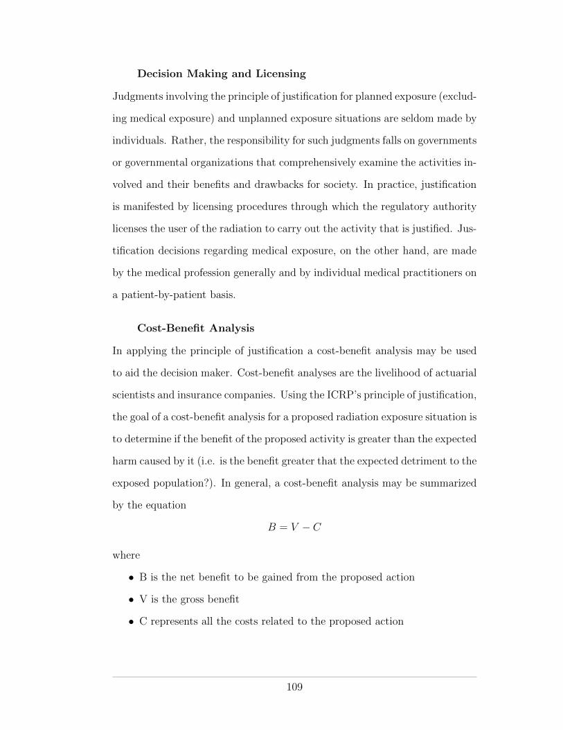
Decision Making and Licensing
Judgments involving the principle of justification for planned exposure (exclud-
ing medical exposure) and unplanned exposure situations are seldom made by
individuals. Rather, the responsibility for such judgments falls on governments
or governmental organizations that comprehensively examine the activities in-
volved and their benefits and drawbacks for society. In practice, justification
is manifested by licensing procedures through which the regulatory authority
licenses the user of the radiation to carry out the activity that is justified. Jus-
tification decisions regarding medical exposure, on the other hand, are made
by the medical profession generally and by individual medical practitioners on
a patient-by-patient basis.
Cost-Benefit Analysis
In applying the principle of justification a cost-benefit analysis may be used
to aid the decision maker. Cost-benefit analyses are the livelihood of actuarial
scientists and insurance companies. Using the ICRP’s principle of justification,
the goal of a cost-benefit analysis for a proposed radiation exposure situation is
to determine if the benefit of the proposed activity is greater than the expected
harm caused by it (i.e. is the benefit greater that the expected detriment to the
exposed population?). In general, a cost-benefit analysis may be summarized
by the equation
B = V � C
where
• B is the net benefit to be gained from the proposed action
• V is the gross benefit
• C represents all the costs related to the proposed action
109
In the case of a radiation exposure situation, V would be the clear benefit
derived from the radiation usage (for example electricity from a nuclear power
plant or images from a diagnostic radiology procedure). C would represent the
sum of the production costs P (for example the cost of constructing a power
plant or radiology room and paying salaries) and the costs of both the level
of radiation protection X that is implemented and the cost of the detriment
Y resulting from residual radiation exposure beyond the level of protection.
Accordingly, for a given radiation exposure situation an appropriate cost-
benefit analysis equation might be
B = V � [P +X + Y ] (7.1)
A cost-benefit analysis of this type is described in ICRP report 37.
7.2.2 The Principle of Optimization
The principle of optimization comes into play if and when an exposure situ-
ation has been justified. It is the principle of most practical interest to the
health physicist. The principle of optimization of protection is defined by the
ICRP as follows:
The principle of optimization: The likelihood of incurring ex-
posure, the number of people exposed, and the magnitude of their
individual doses should all be kept as low as reasonably achievable,
taking into account economic and societal factors.
It is clear from the wording that the principle of optimization is in essence the
ALARA principle. In theory the cost-benefit analysis outlined above can be
extended to perform an optimization analysis. The gross benefit V and the
production costs P are fixed and presumably quantifiable for any radiation
exposure situation. The cost of radiation protection X and the cost of the
110
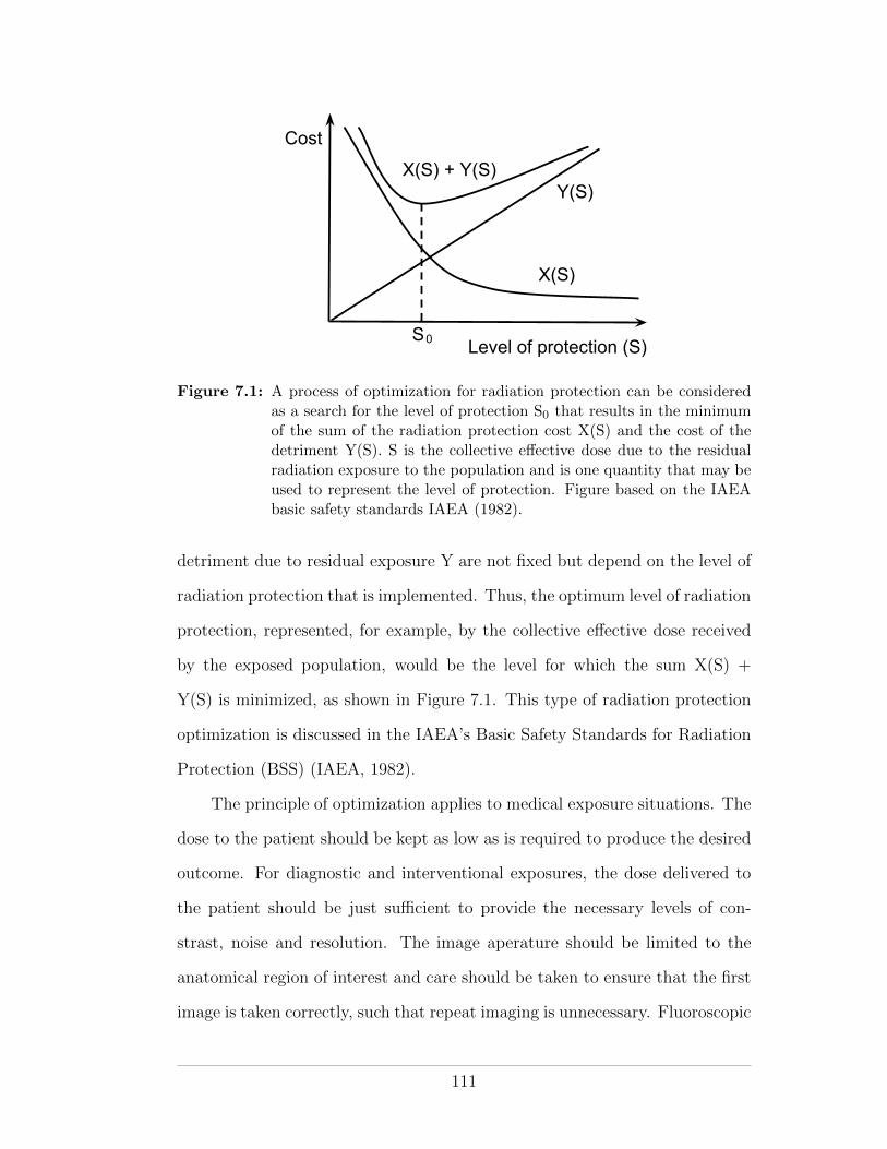
Cost
Level of protection (S)S0
X(S)
Y(S)X(S) + Y(S)
Figure 7.1: A process of optimization for radiation protection can be consideredas a search for the level of protection S0 that results in the minimumof the sum of the radiation protection cost X(S) and the cost of thedetriment Y(S). S is the collective e↵ective dose due to the residualradiation exposure to the population and is one quantity that may beused to represent the level of protection. Figure based on the IAEAbasic safety standards IAEA (1982).
detriment due to residual exposure Y are not fixed but depend on the level of
radiation protection that is implemented. Thus, the optimum level of radiation
protection, represented, for example, by the collective e↵ective dose received
by the exposed population, would be the level for which the sum X(S) +
Y(S) is minimized, as shown in Figure 7.1. This type of radiation protection
optimization is discussed in the IAEA’s Basic Safety Standards for Radiation
Protection (BSS) (IAEA, 1982).
The principle of optimization applies to medical exposure situations. The
dose to the patient should be kept as low as is required to produce the desired
outcome. For diagnostic and interventional exposures, the dose delivered to
the patient should be just su�cient to provide the necessary levels of con-
strast, noise and resolution. The image aperature should be limited to the
anatomical region of interest and care should be taken to ensure that the first
image is taken correctly, such that repeat imaging is unnecessary. Fluoroscopic
111
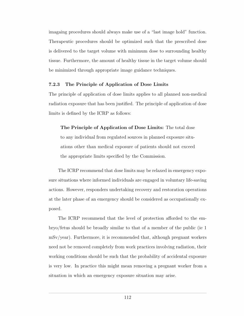
imagaing procedures should always make use of a “last image hold” function.
Therapeutic procedures should be optimized such that the prescribed dose
is delivered to the target volume with minimum dose to surrounding healthy
tissue. Furthermore, the amount of healthy tissue in the target volume should
be minimized through appropriate image guidance techniques.
7.2.3 The Principle of Application of Dose Limits
The principle of application of dose limits applies to all planned non-medical
radiation exposure that has been justified. The principle of application of dose
limits is defined by the ICRP as follows:
The Principle of Application of Dose Limits: The total dose
to any individual from regulated sources in planned exposure situ-
ations other than medical exposure of patients should not exceed
the appropriate limits specified by the Commission.
The ICRP recommend that dose limits may be relaxed in emergency expo-
sure situations where informed individuals are engaged in voluntary life-saving
actions. However, responders undertaking recovery and restoration operations
at the later phase of an emergency should be considered as occupationally ex-
posed.
The ICRP recommend that the level of protection a↵orded to the em-
bryo/fetus should be broadly similar to that of a member of the public (ie 1
mSv/year). Furthermore, it is recommended that, although pregnant workers
need not be removed completely from work practices involving radiation, their
working conditions should be such that the probability of accidental exposure
is very low. In practice this might mean removing a pregnant worker from a
situation in which an emergency exposure situation may arise.
112
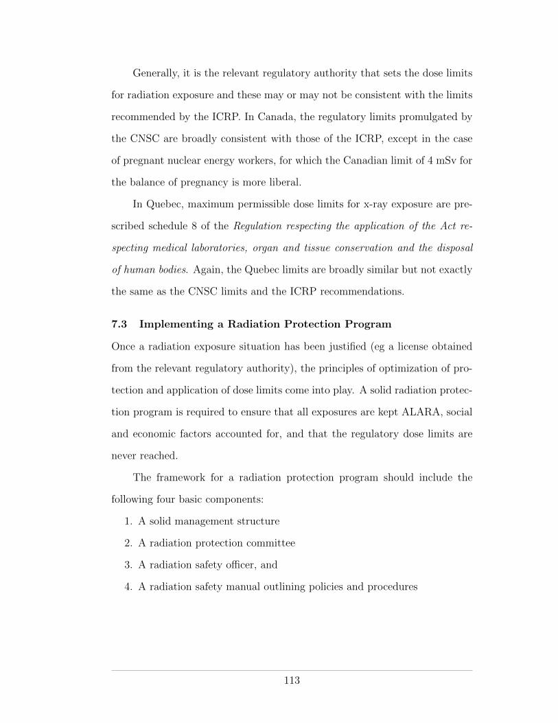
Generally, it is the relevant regulatory authority that sets the dose limits
for radiation exposure and these may or may not be consistent with the limits
recommended by the ICRP. In Canada, the regulatory limits promulgated by
the CNSC are broadly consistent with those of the ICRP, except in the case
of pregnant nuclear energy workers, for which the Canadian limit of 4 mSv for
the balance of pregnancy is more liberal.
In Quebec, maximum permissible dose limits for x-ray exposure are pre-
scribed schedule 8 of the Regulation respecting the application of the Act re-
specting medical laboratories, organ and tissue conservation and the disposal
of human bodies. Again, the Quebec limits are broadly similar but not exactly
the same as the CNSC limits and the ICRP recommendations.
7.3 Implementing a Radiation Protection Program
Once a radiation exposure situation has been justified (eg a license obtained
from the relevant regulatory authority), the principles of optimization of pro-
tection and application of dose limits come into play. A solid radiation protec-
tion program is required to ensure that all exposures are kept ALARA, social
and economic factors accounted for, and that the regulatory dose limits are
never reached.
The framework for a radiation protection program should include the
following four basic components:
1. A solid management structure
2. A radiation protection committee
3. A radiation safety o�cer, and
4. A radiation safety manual outlining policies and procedures
113
Chief Executive Officer
Director Quality and Safety
Director Medical Physics
Administrative Director Patient
Services
Radiation Safety Officer
Radiation Safety Committee
Departmental directors and/or representatives of
professionals that use radiation for medical purposes
Reports to
Line of communication
Sits on
Figure 7.2: Organigram showing the organization of communication and reportingfor a generic hospital radiation safety program.
Management Structure
Just as is the case for other health and safety programs, a radiation protection
program cannot exist unless it is underpinned by a solid management struc-
ture. Roles and responsibilities with regard to radiation protection should be
clearly delineated. Organigrams are often used for this purpose. An organ-
igram is a chart that illustrates the relationships between di↵erent members
of an organization. Figure 7.2 presents a generic radiation safety organigram
that might be used in a hospital.
114
A radiation safety o�cer with competency in radiation protection should
be appointed. Indeed, an RSO is usually mandated by the applicable regula-
tions. A multi-professional radiation safety committee should also be formed
and entrusted with the tasks of monitoring the radiation protection program
and reaching consensus on important radiation protection decisions. The roles
of the RSO and RPC are discussed in greater detail below.
Commitment to the principle of ALARA by senior management is vital in
order for a radiation protection program to succeed. Often a statement of sup-
port is written into the radiation safety manual. The commitment should be
backed up with practical support in terms of the resources needed (man-power,
time and money) to implement an optimized radiation protection program.
Radiation Protection Committee
The role of the radiation protection committee is to oversee the radiation pro-
tection program, to ensure compliance with the principle of ALARA and with
federal and provincial regulations. The committee is responsible for reach-
ing consensus on important decisions regarding radiation protection and for
procuring, from senior management, the resources necessary to maintain the
radiation protection program.
The radiation protection committee is the focal point for the radiation
protection program and as such it should be multi-professional in composition.
It should include the RSO and representatives of all the radiation users within
the organization. For example, in a hospital the radiation protection commit-
tee might include representatives of physicians, nurses, therapists, physicists,
senior management and the department of quality and safety. The committee
should meet regularly, for example once per quarter, to review the radiation
safety program.
115
Radiation Safety O�cer
The RSO is responsible for the implementation, coordination, and day-to-
day oversight of the radiation protection program (AAPM Task Group 160,
2010). The RSO is not normally responsible for the direct supervision of
radiation users in their daily work but he/she should have the authority to
enforce policies and procedures dealing with radiation safety and regulatory
compliance. RSO responsibilities include the following:
• Sit on the radiation protection committee
• Oversee the operational aspects of the radiation protection program and
delegate tasks as appropriate
• Ensure compliance with applicable regulations and license requirements
• Help identify and resolve radiation protection problems
• Stop unsafe practises
• Notify management and the regulatory authorities of radiation safety
problems and corrective actions, as appropriate
• Liaise with the regulatory authorities (ie paperwork)
• Act as the contact person for all matters related to radiation safety
• Perform leak checks as mandated in the CNSC regulations and submit
compliance reports as appropriate
• Coordinate education and training of sta↵ for matters pertaining to ra-
diation safety
• Maintain a calibrated working inventory of radiation safety equipment
• Designate nuclear energy workers
• Edit/maintain the radiation safety manual
The the presence of an RSO may be mandated by the applicable regula-
tions. For example, the CNSC Class II regulations mandate an RSO who is
116
certified by the CNSC after undergoing a CNSC certification exam. Accord-
ing to the regulations, the RSO must have a designated replacement (DR),
essentially a second person in the institution who is qualified to perform the
duties of the RSO in his/her absence. The RSO or DR must be present at
the licensed Class II facility for at least a portion of each day and must be
contactable o↵-hours when the class II equipment is operated by “qualified
persons”. Backup RSOs are also mandated but need not be certified by the
CNSC. Backup RSOs may perform some of the duties of the RSO (such as
dealing with shipping/receiving, emergencies, pregnant nuclear energy worker
designation and minor contact with the CNSC) when neither the RSO nor the
DR are on site.
Radiation Safety Manual
An updated radiation safety manual is a very useful reference within an or-
ganization regarding radiation protection policies and procedures. It should
cover all aspects of radiation safety policy within the organization and copies
should be accessible to all members of sta↵.
Components of a Radiation Safety Program
The following is a list of items and activities (some of which have been
mentioned already) that comprise a typical radiation safety program:
• ALARA policy
• Radiation safety o�cer
• Radiation safety committee
• Radiation safety manual
• Education/training for sta↵
• Shipping/receiving of radioactive substances
• Waste disposal
117
• Dose limits including limits for pregnant nuclear energy workers
• Nuclear energy worker designation
• Dose monitoring (personnel and area)
• Emergency planning
• Paperwork (e.g., regulatory communications, records)
• Signage
• Inventory and calibration of radiation protection equipment
• Facility design and modification
• Incident reporting
• Emergency planning/response
• Leak testing
118
CHAPTER 8Radiation in Healthcare
The discovery of x-rays at the end of 1895 represents one of the finest examples
of translational science - Roentgen’s demonstration that he could image human
anatomy (namely his wifes hand) went from laboratory experiment to medical
practise within weeks of his reporting it. In fact, the first Canadian x-ray
image was taken in early 1896 at the Montreal General Hospital by McGill
physics professor John Cox just a few months after Roentgen’s publication.
Today the use of ionizing radiation is firmly established in diagnostic and
therapeutic medicine. Currently approximately 4 billion medical procedures
with ionizing radiation are performed annually worldwide, making medical
radiation the largest, and still growing, artificial contribution to background
radiation.
Radiation has three main applications in medicine:
• Diagnosis
• Intervention, and
• Therapy
Additionally radiation is used in healthcare for biomedical research, for the
sterilization of blood and medical equipment and in the production of radionu-
clides for nuclear medicine.
In this chapter we will briefly examine each of the above modalities and
outline associated radiation protection considerations.
Please refer to the notes presented in class.
119
CHAPTER 9Radiation Shielding for Medical Linear Accelerators
Internationally accepted guidelines for the design of structural shielding for
radiation therapy installations are laid out in the National Council for Ra-
diation Protection report number 151 (NCRP, 2005) and in the Institute of
Physics and Engineering in Medicine (IPEM) report number 75 (IPEM, 1997),
herein referred to as just NCRP 151 and IPEM 75, respectively. These reports
detail the calculations involved in determining the barrier thickness needed to
shield an individual from a source of radiation such that his/her e↵ective doses
are kept well below the appropriate maximum permissible values. They also
provide general recommendations for the design of shielding around radiation
therapy installations. A third report, the IAEA Safety Reports Series (SRS)
No. 47. (IAEA, 2006), draws upon both NCRP 151 and IPEM 75 and is
available free of charge on the IAEA website1 .
This chapter describes the calculation methodology of the NCRP report,
currently the standard shielding design document used for radiation therapy
facilities in North America. This report, along with the NCRP report number
49, was used in the design calculations for the Radiation Oncology department
at the Montreal General Hospital.
9.1 Equivalent and E↵ective Doses
The NCRP 151 authors use equivalent dose H as the single dose quantity
of interest in all shielding calculations. They do so, despite the fact that
1 http://www-pub.iaea.org/MTCD/publications/PDF/Pub1223 web.pdf
120
the ICRP and NCRP dose limit recommendations and the legal maxima pre-
scribed by regulatory bodies, including the CNSC, are for both equivalent
dose and e↵ective dose. The reason to use equivalent dose alone is a matter of
practicality—it is simply unfeasible to estimate e↵ective dose values without
exact prior knowledge of quantities such as the position, size and posture of
the person who is exposed.
9.2 Production of Therapeutic Radiation Beams
Megavoltage therapeutic photon and electron beams are typically produced
using linear accelerators. To produce an X-ray beam, a linear accelerator ac-
celerates electrons toward a target whereupon bremsstrahlung X-ray photons
and heat are produced. To produce an electron beam, the target is removed.
As shown in Figure 9.1, there are several major components to a therapeutic
linear accelerator: the gantry, the gantry stand and support, the head, the
patient couch and the control console.
Depending on the type of linear accelerator involved, the radiation beam
may be formed in the gantry stand or within the gantry itself (as is the case
in Figure 9.1). Electrons are produced by means of thermionic emission and
acceleration o↵ a heated cathode within a device known as an electron gun.
From the electron gun, the electrons drift into an accelerating RF waveguide.
Within the waveguide they are accelerated to MeV energies as a result of
energy transfer to them from the high-power RF field. The beam transport
system controls delivery of the energetic pulsed electron beam from the waveg-
uide to the target (for an X-ray beam) or to a scattering foil (for an electron
beam). The purpose of the scattering foil is to spread out the otherwise nar-
row electron beam. Before reaching the patient, the beam is shaped within
the head of the unit using collimating jaws made of high-Z material or using a
121
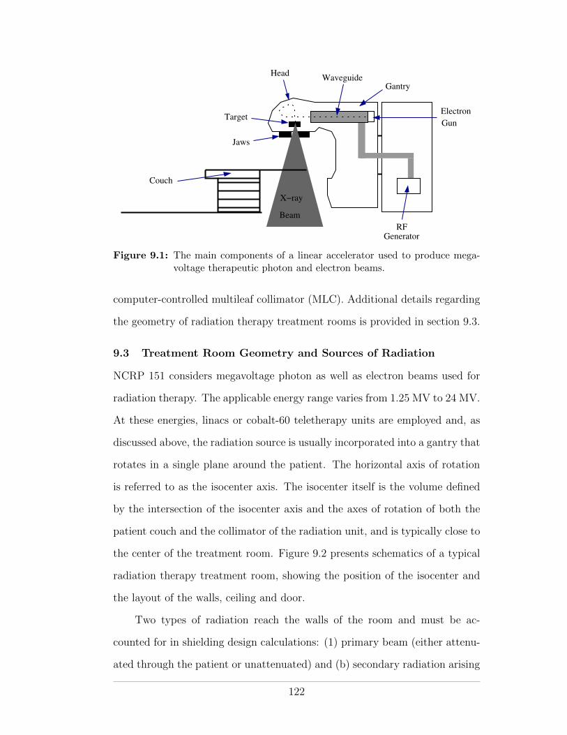
Electron
Gun
Jaws
Target
WaveguideGantry
RFGenerator
Couch
Beam
X−ray
Head
Figure 9.1: The main components of a linear accelerator used to produce mega-voltage therapeutic photon and electron beams.
computer-controlled multileaf collimator (MLC). Additional details regarding
the geometry of radiation therapy treatment rooms is provided in section 9.3.
9.3 Treatment Room Geometry and Sources of Radiation
NCRP 151 considers megavoltage photon as well as electron beams used for
radiation therapy. The applicable energy range varies from 1.25 MV to 24 MV.
At these energies, linacs or cobalt-60 teletherapy units are employed and, as
discussed above, the radiation source is usually incorporated into a gantry that
rotates in a single plane around the patient. The horizontal axis of rotation
is referred to as the isocenter axis. The isocenter itself is the volume defined
by the intersection of the isocenter axis and the axes of rotation of both the
patient couch and the collimator of the radiation unit, and is typically close to
the center of the treatment room. Figure 9.2 presents schematics of a typical
radiation therapy treatment room, showing the position of the isocenter and
the layout of the walls, ceiling and door.
Two types of radiation reach the walls of the room and must be ac-
counted for in shielding design calculations: (1) primary beam (either attenu-
ated through the patient or unattenuated) and (b) secondary radiation arising
122
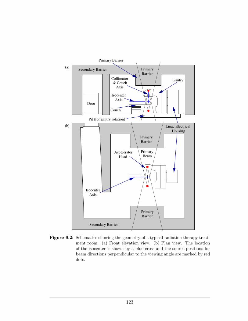
HousingLinac Electrical
IsocenterAxis
Primary Barrier
Gantry
Pit (for gantry rotation)
Couch
Secondary Barrier
AcceleratorHead
Door
PrimaryBeam
PrimaryBarrier
PrimaryBarrier
PrimaryBarrier
(a)
(b)
IsocenterAxis
Secondary Barrier
Collimator& Couch
Axis
Figure 9.2: Schematics showing the geometry of a typical radiation therapy treat-ment room. (a) Front elevation view. (b) Plan view. The locationof the isocenter is shown by a blue cross and the source positions forbeam directions perpendicular to the viewing angle are marked by reddots.
123
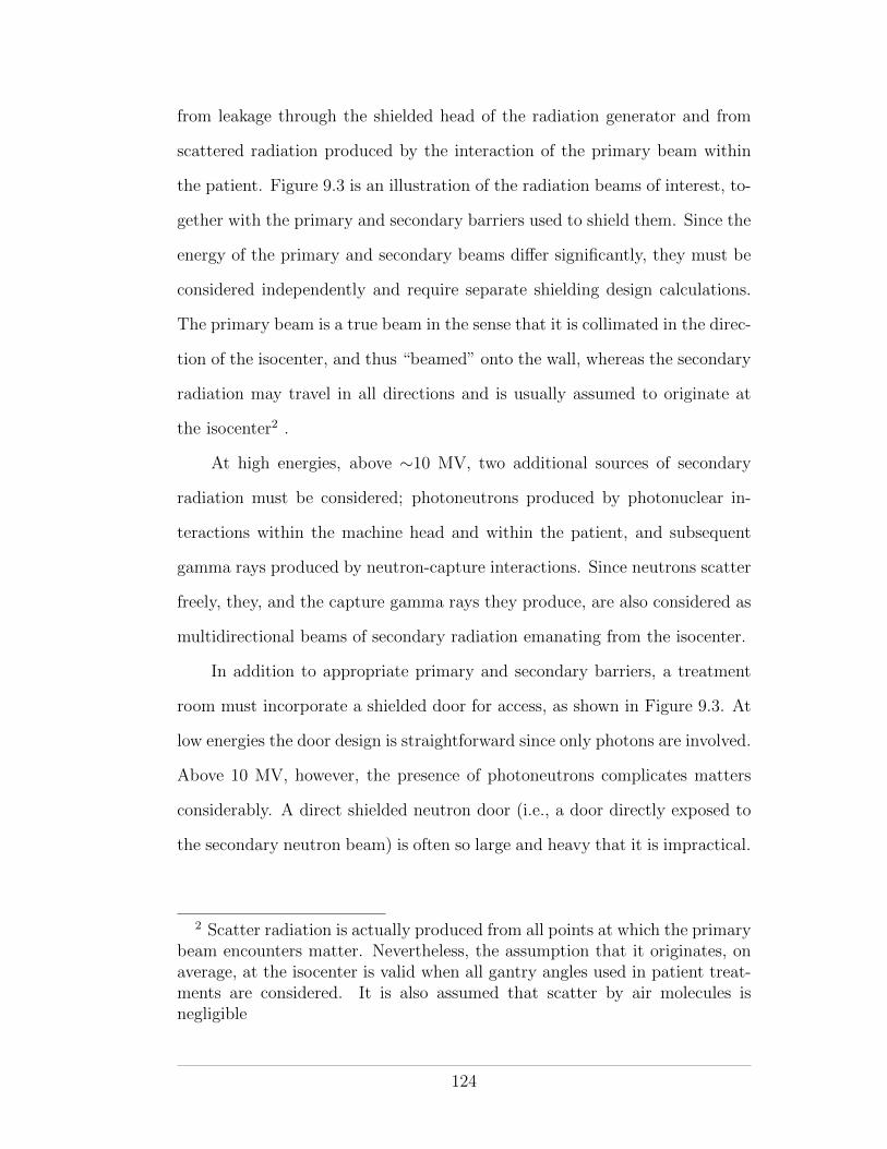
from leakage through the shielded head of the radiation generator and from
scattered radiation produced by the interaction of the primary beam within
the patient. Figure 9.3 is an illustration of the radiation beams of interest, to-
gether with the primary and secondary barriers used to shield them. Since the
energy of the primary and secondary beams di↵er significantly, they must be
considered independently and require separate shielding design calculations.
The primary beam is a true beam in the sense that it is collimated in the direc-
tion of the isocenter, and thus “beamed” onto the wall, whereas the secondary
radiation may travel in all directions and is usually assumed to originate at
the isocenter2 .
At high energies, above ⇠10 MV, two additional sources of secondary
radiation must be considered; photoneutrons produced by photonuclear in-
teractions within the machine head and within the patient, and subsequent
gamma rays produced by neutron-capture interactions. Since neutrons scatter
freely, they, and the capture gamma rays they produce, are also considered as
multidirectional beams of secondary radiation emanating from the isocenter.
In addition to appropriate primary and secondary barriers, a treatment
room must incorporate a shielded door for access, as shown in Figure 9.3. At
low energies the door design is straightforward since only photons are involved.
Above 10 MV, however, the presence of photoneutrons complicates matters
considerably. A direct shielded neutron door (i.e., a door directly exposed to
the secondary neutron beam) is often so large and heavy that it is impractical.
2 Scatter radiation is actually produced from all points at which the primarybeam encounters matter. Nevertheless, the assumption that it originates, onaverage, at the isocenter is valid when all gantry angles used in patient treat-ments are considered. It is also assumed that scatter by air molecules isnegligible
124
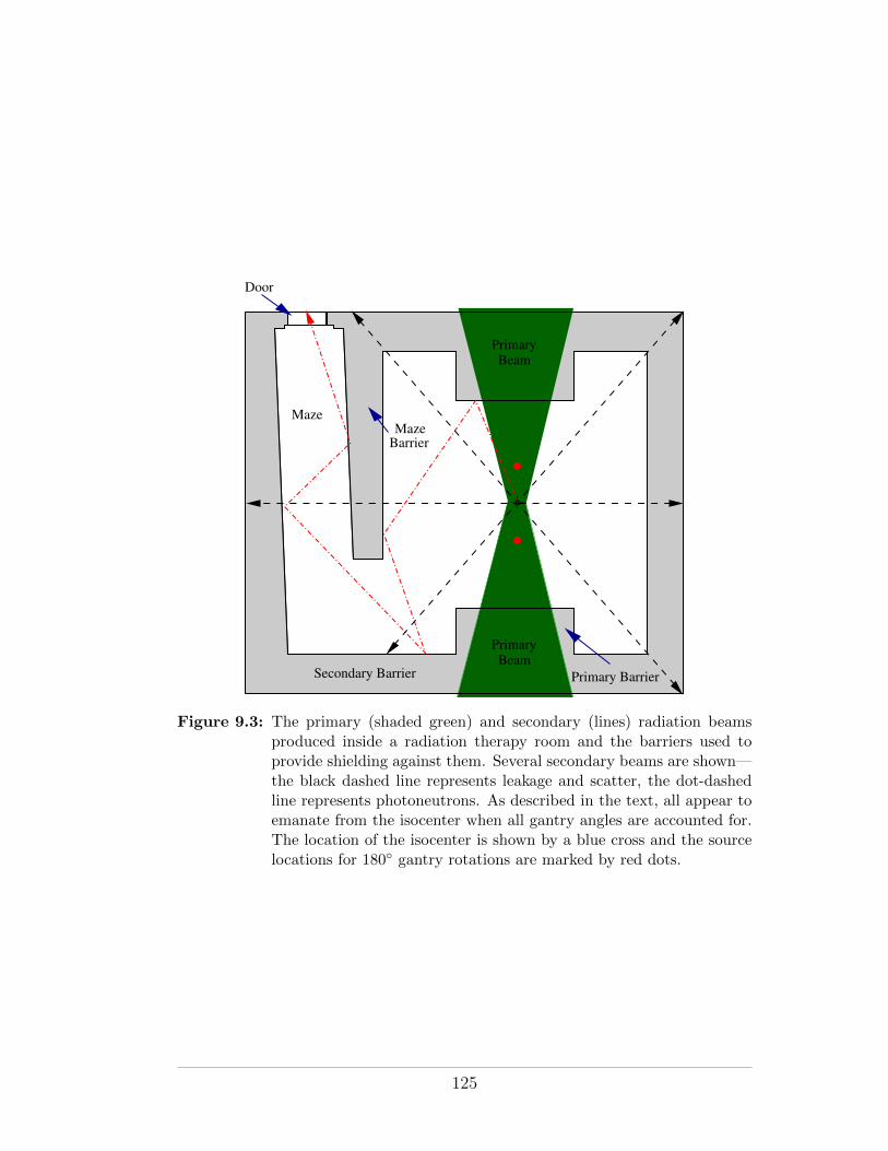
BarrierMaze
Secondary Barrier Primary Barrier
Maze
Door
PrimaryBeam
PrimaryBeam
Figure 9.3: The primary (shaded green) and secondary (lines) radiation beamsproduced inside a radiation therapy room and the barriers used toprovide shielding against them. Several secondary beams are shown—the black dashed line represents leakage and scatter, the dot-dashedline represents photoneutrons. As described in the text, all appear toemanate from the isocenter when all gantry angles are accounted for.The location of the isocenter is shown by a blue cross and the sourcelocations for 180� gantry rotations are marked by red dots.
125
Additional secondary barrier shielding to attenuate the secondary radiation
before it reaches the door is required. A “maze” wall, forming a corridor from
the door to the far wall of the room, is the solution. The treatment room
depicted in Figures 9.2 and 9.3 incorporates a maze.
9.4 Shielding Materials
The shielding properties of a number of materials are detailed in chapter 4
of NCRP 151. Table 9.1 provides a summary. A comparison of materials
used for photon shielding in megavoltage radiation therapy is quite straight-
forward since only a density comparison is required. This is due to the dom-
inance of the Compton e↵ect at megavoltage energies (see Figure 2.6) and
the Z-independence of the Compton e↵ect. However, with regard to shielding
radiation from linear accelerators that accelerate electrons to energies above
10 MV, the ability of an attenuating material to absorb or moderate neutrons
is an important additional consideration. High-Z materials, such as lead and
steel are nearly transparent to fast neutrons, although they do moderate their
energies. Materials with high hydrogen content (e.g., concrete) or borated
materials (such as borated-polyethylene) are the best neutron absorbers.
9.5 Overview of Shielding Calculations
The purpose of any radiation shielding calculation is to determine the thickness
of a barrier needed to reduce the radiation dose received at a point of interest
(POI) at one side of the barrier, due to a radiation source at the other side, to
a desired level. In NCRP 151, the desired radiation level is called the “design
goal” P . Its value is equal to the regulatory dose limit modulated by an
appropriate ALARA factor (see section 4.5.2). Figure 9.4 graphically depicts
the geometry, distances and quantities involved in a shielding calculation.
126
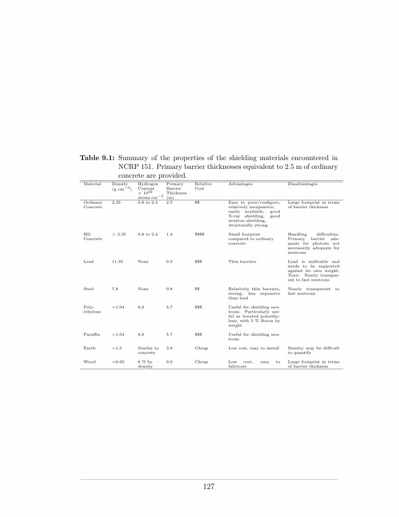
Table 9.1: Summary of the properties of the shielding materials encountered inNCRP 151. Primary barrier thicknesses equivalent to 2.5 m of ordinaryconcrete are provided.
Material Density
(g cm�3)
HydrogenContent⇥ 1022
atoms cm�3
PrimaryBarrierThickness(m)
RelativeCost
Advantages Disadvantages
OrdinaryConcrete
2.35 0.8 to 2.4 2.5 $$ Easy to pour/configure,relatively inexpensive,easily available, goodX-ray shielding, goodneutron shielding,structurally strong
Large footprint in termsof barrier thickness
HDConcrete
> 2.35 0.8 to 2.4 1.4 $$$$ Small footprintcompared to ordinaryconcrete
Handling di�culties.Primary barrier ade-quate for photons notnecessarily adequate forneutrons
Lead 11.35 None 0.5 $$$ Thin barriers Lead is malleable andneeds to be supportedagainst its own weight.Toxic. Nearly transpar-ent to fast neutrons
Steel 7.8 None 0.8 $$ Relatively thin barriers,strong, less expensivethan lead
Nearly transparent tofast neutrons
Poly-ethylene
⇠1.04 8.0 5.7 $$$ Useful for shielding neu-trons. Particularly use-ful as borated polyethy-lene, with 5 % Boron byweight
Para�n ⇠1.04 8.0 5.7 $$$ Useful for shielding neu-trons
Earth ⇠1.5 Similar toconcrete
3.9 Cheap Low cost, easy to install Density may be di�cultto quantify
Wood ⇠0.65 6 % bydensity
9.0 Cheap Low cost, easy tofabricate
Large footprint in termsof barrier thickness
127
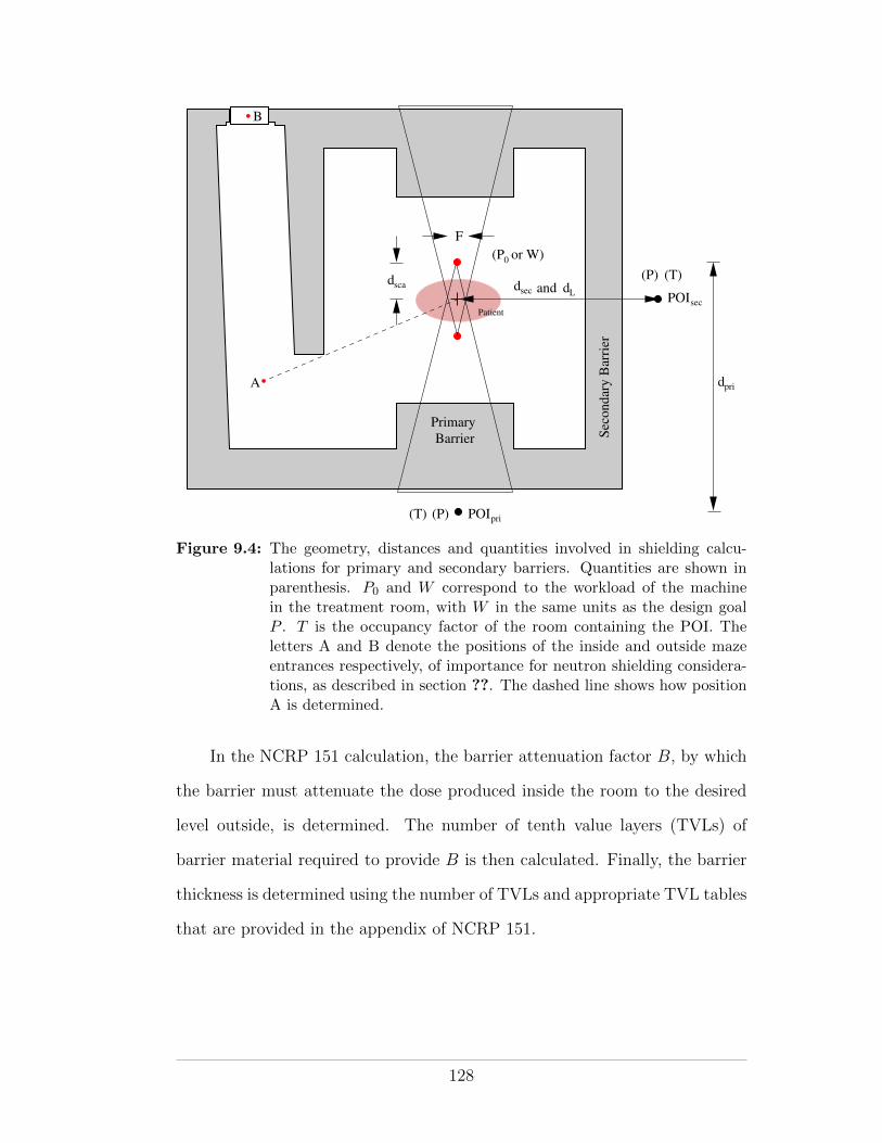
POIpri
POIsec
0(P or W)
dsca dsec dL
BarrierPrimary
dpri
(P)
(P) (T)
(T)
F
and
Sec
ondar
y B
arri
er
Patient
A
B
Figure 9.4: The geometry, distances and quantities involved in shielding calcu-lations for primary and secondary barriers. Quantities are shown inparenthesis. P0 and W correspond to the workload of the machinein the treatment room, with W in the same units as the design goalP . T is the occupancy factor of the room containing the POI. Theletters A and B denote the positions of the inside and outside mazeentrances respectively, of importance for neutron shielding considera-tions, as described in section ??. The dashed line shows how positionA is determined.
In the NCRP 151 calculation, the barrier attenuation factor B, by which
the barrier must attenuate the dose produced inside the room to the desired
level outside, is determined. The number of tenth value layers (TVLs) of
barrier material required to provide B is then calculated. Finally, the barrier
thickness is determined using the number of TVLs and appropriate TVL tables
that are provided in the appendix of NCRP 151.
128
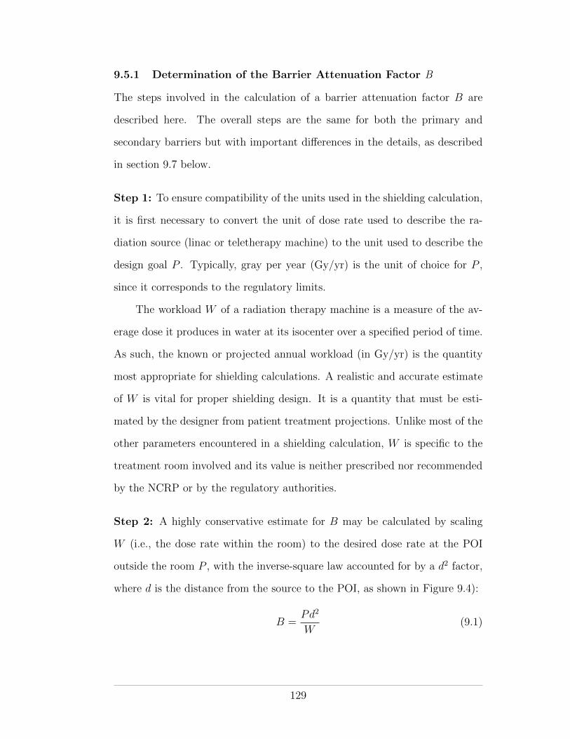
9.5.1 Determination of the Barrier Attenuation Factor B
The steps involved in the calculation of a barrier attenuation factor B are
described here. The overall steps are the same for both the primary and
secondary barriers but with important di↵erences in the details, as described
in section 9.7 below.
Step 1: To ensure compatibility of the units used in the shielding calculation,
it is first necessary to convert the unit of dose rate used to describe the ra-
diation source (linac or teletherapy machine) to the unit used to describe the
design goal P . Typically, gray per year (Gy/yr) is the unit of choice for P ,
since it corresponds to the regulatory limits.
The workload W of a radiation therapy machine is a measure of the av-
erage dose it produces in water at its isocenter over a specified period of time.
As such, the known or projected annual workload (in Gy/yr) is the quantity
most appropriate for shielding calculations. A realistic and accurate estimate
of W is vital for proper shielding design. It is a quantity that must be esti-
mated by the designer from patient treatment projections. Unlike most of the
other parameters encountered in a shielding calculation, W is specific to the
treatment room involved and its value is neither prescribed nor recommended
by the NCRP or by the regulatory authorities.
Step 2: A highly conservative estimate for B may be calculated by scaling
W (i.e., the dose rate within the room) to the desired dose rate at the POI
outside the room P , with the inverse-square law accounted for by a d2 factor,
where d is the distance from the source to the POI, as shown in Figure 9.4):
B =Pd2
W(9.1)
129
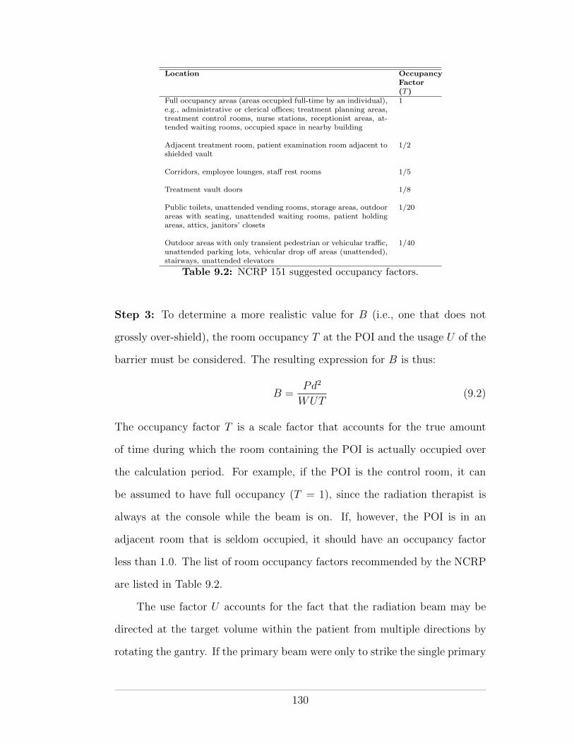
Location OccupancyFactor(T )
Full occupancy areas (areas occupied full-time by an individual),e.g., administrative or clerical o�ces; treatment planning areas,treatment control rooms, nurse stations, receptionist areas, at-tended waiting rooms, occupied space in nearby building
1
Adjacent treatment room, patient examination room adjacent toshielded vault
1/2
Corridors, employee lounges, sta↵ rest rooms 1/5
Treatment vault doors 1/8
Public toilets, unattended vending rooms, storage areas, outdoorareas with seating, unattended waiting rooms, patient holdingareas, attics, janitors’ closets
1/20
Outdoor areas with only transient pedestrian or vehicular tra�c,unattended parking lots, vehicular drop o↵ areas (unattended),stairways, unattended elevators
1/40
Table 9.2: NCRP 151 suggested occupancy factors.
Step 3: To determine a more realistic value for B (i.e., one that does not
grossly over-shield), the room occupancy T at the POI and the usage U of the
barrier must be considered. The resulting expression for B is thus:
B =Pd2
WUT(9.2)
The occupancy factor T is a scale factor that accounts for the true amount
of time during which the room containing the POI is actually occupied over
the calculation period. For example, if the POI is the control room, it can
be assumed to have full occupancy (T = 1), since the radiation therapist is
always at the console while the beam is on. If, however, the POI is in an
adjacent room that is seldom occupied, it should have an occupancy factor
less than 1.0. The list of room occupancy factors recommended by the NCRP
are listed in Table 9.2.
The use factor U accounts for the fact that the radiation beam may be
directed at the target volume within the patient from multiple directions by
rotating the gantry. If the primary beam were only to strike the single primary
130
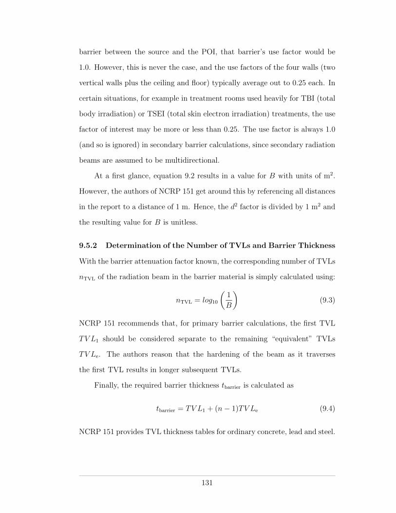
barrier between the source and the POI, that barrier’s use factor would be
1.0. However, this is never the case, and the use factors of the four walls (two
vertical walls plus the ceiling and floor) typically average out to 0.25 each. In
certain situations, for example in treatment rooms used heavily for TBI (total
body irradiation) or TSEI (total skin electron irradiation) treatments, the use
factor of interest may be more or less than 0.25. The use factor is always 1.0
(and so is ignored) in secondary barrier calculations, since secondary radiation
beams are assumed to be multidirectional.
At a first glance, equation 9.2 results in a value for B with units of m2.
However, the authors of NCRP 151 get around this by referencing all distances
in the report to a distance of 1 m. Hence, the d2 factor is divided by 1 m2 and
the resulting value for B is unitless.
9.5.2 Determination of the Number of TVLs and Barrier Thickness
With the barrier attenuation factor known, the corresponding number of TVLs
nTVL of the radiation beam in the barrier material is simply calculated using:
nTVL = log10
✓1
B
◆(9.3)
NCRP 151 recommends that, for primary barrier calculations, the first TVL
TV L1 should be considered separate to the remaining “equivalent” TVLs
TV Le. The authors reason that the hardening of the beam as it traverses
the first TVL results in longer subsequent TVLs.
Finally, the required barrier thickness tbarrier is calculated as
tbarrier = TV L1 + (n� 1)TV Le (9.4)
NCRP 151 provides TVL thickness tables for ordinary concrete, lead and steel.
131
9.6 Primary Barrier Calculation
All the factors discussed above considered, the barrier attenuation factor for
the primary beam is given by the equation:
Bpri =Pd2priWUT
(9.5)
where a use factor less than 1.0 is typically employed. In calculating the
primary barrier thickness, NCRP 151 makes the conservative assumption that
the primary beam is unattenuated in traversing the patient (this is not the case
in IPEM 75). Accordingly, when undertaking a post-construction radiation
survey, a phantom should not be used in evaluating the primary barrier, if
survey results are to be compared with NCRP 151 predictions.
9.7 Secondary Barrier Calculation
The secondary barrier must shield against both the leakage and scatter radi-
ations. As can be seen in figure 2.6, at megavoltage energies the dominant
photon interaction is the Compton e↵ect. In the Compton interaction, the
photon is not absorbed, rather it is scattered at an angle and with reduced
energy. Both the leakage and scatter radiations undergo Compton scattering.
The leakage beam scatters multiple times, and thus looses significant energy,
while traversing the dense material (typically lead) in the head of the radia-
tion generator. The scatter radiation, by definition, is scattered at least once
before reaching the secondary barrier.
Two main sources of scatter radiation are possible: (1) scatter radiation
produced by scattering of the primary beam within the patient, and (2) scatter
radiation produced by scattering of the primary and patient scatter radiations
with the walls and fixtures of the treatment room. A secondary barrier with
thickness adequate to attenuate: (1) will generally be su�cient for (2), since
132
multiple scattering interactions reduce photon energy and penetrability signif-
icantly.
Barrier thicknesses are calculated for the leakage and patient-scatter beams
independently due to the di↵erence in energy between them. Leakage radia-
tion, having undergone multiple scattering within the head of the treatment
machine, is typically of a much lower energy than the patient-scatter radiation,
which is scattered less often before reaching the walls.
As mentioned previously, a use factor of unity is used in secondary barrier
calculations, since the secondary radiations are emitted in all directions.
Shielding Calculation for Leakage Radiation
IEC (International Electrotechnical Commission) regulations stipulate that
the leakage from the head of a radiation-therapy unit must not exceed an av-
erage of 0.1 % and a maximum of 0.2 % of the primary beam over a 2 m radius
measured from the beam central axis in the plane of the patient (IEC Publi-
cation 601-2-1, 1981). NCRP 151 takes a conservative approach and simply
assumes that the leakage is equal to 0.1 % of the primary beam, even though
the authors point out that manufacturers generally shield their machines to
better than 0.1 %. The barrier attenuation factor for the leakage beam alone
is thus given by the equation:
BL =Pd2L
10�3WLT, (9.6)
where dL corresponds to the distance from the POI to the source of the leak-
age, which, as shown in Figure 9.4, generally averages to the isocenter. The
leakage workload WL may be assumed to be equal to the normal workload W
except for clinical practice that involves a large component of IMRT—in IMRT
133
treatments, small field sizes are used and more “beam-on” time (larger leak-
age workload) is required to produce the same absorbed dose at the isocenter.
Leakage-specific TVL tables are provided in the appendix of NCRP 151.
Shielding Calculation for Patient Scattered Radiation
The barrier attenuation equation used for patient scattered radiation is
Bps =P
↵WTd2scad
2sec
400
F, (9.7)
where (with reference to Figure 9.4):
• ↵ is the scatter fraction or the fraction of the primary beam absorbed
dose that scatters at a particular angle. Scatter fraction tables are pro-
vided in the appendix of NCRP 151.
• dsca is the distance from the primary radiation source to the scattering
material (the patient). Usually taken as the SAD of the machine.
• dsec is the distance from the scattering point to the POI.
• F is the treatment field area (in cm2) at the isocenter. The factor of 400
accounts for the fact that the scatter fractions provided in NCRP 151
are normalized to those measured for a 20 cm ⇥ 20 cm field size.
The scattering angle does not directly enter into the barrier attenuation equa-
tion but is considered instead in the scatter fraction lookup-table.
The Two Source Rule
Using the calculated barrier attenuation factors BL and Bps, for leakage and
patient-scatter, respectively, the final required thickness of the shielding mate-
rial can be determined. The barrier thicknesses required for each are compared
as though there were two separate sources in the treatment room. If they are
about the same (less than 1 TVL di↵erence), then their combined dose at the
POI should be about double their individual values. A half value layer (HVL)
134
is, therefore, added to the greater of the two to reduce the combined dose by
one half. If the thicknesses di↵er significantly (by 1 TVL or more), the larger
thickness will provide adequate shielding for both.
9.8 Maze and Door Calculations
As mentioned previously, the door of a treatment room controls access to the
room while simultaneously providing shielding. One could employ a direct
shielded door made from lead or steel and simply use the NCRP secondary
barrier calculation methodology to determine its thickness. While adequate
at low energies, such a direct shielded door would become prohibitively im-
practical at high energies where the secondary radiation is more penetrating.
Above 10 MV, photoneutrons and neutron-capture gamma rays are an addi-
tional hazard that require further shielding. The solution is a maze barrier to
attenuate the secondary radiation before it reaches the door. Figure 9.3 shows
the geometry of a maze wall.
NCRP 151 provides a recipe to calculate the reduced secondary dose at
the treatment room door when a maze is used. With regard to photon dose,
the calculation method is the same regardless of energy; the energy being
accounted for in the tabulated data provided. At high energies, however,
the photoneutron and neutron-capture gamma-ray dose must be added to the
photon dose.
9.8.1 Door Design
The thickness of the door required for a radiation therapy room may be cal-
culated once the dose at the door has been established. For low-energy ac-
celerator rooms, the door typically comprises a lead barrier encased in steel
for rigidity. The transmission factor for the lead is calculated by dividing the
135
shielding design goal P for the area outside the door by the photon dose deter-
mined just inside it. The design goal may be modulated by the 1/8 occupancy
factor, as per Table 9.2.
Doors used for high-energy accelerator rooms must shield against the pho-
ton dose together with the neutron and neutron-capture gamma-ray doses. A
door comprising a sandwich of lead, borated-polyethylene (BPE) and lead, en-
cased in steel is typically employed. The inner layer of lead serves to moderate
fast neutrons from the treatment room by inelastic scattering, making the cen-
tral layer of BPE more e↵ective at thermalizing and absorbing them.3 The
outer layer of lead serves to attenuate the gamma rays that result from neu-
tron capture by the boron. Once transmission factors have been established,
both for lead and BPE, the required thicknesses of each may be determined
from tables provided in the appendix of NCRP 151.
9.9 Radiation Shielding Evaluation
Following installation of a new radiation therapy device, an evaluation of the
adequacy of the treatment room shielding is necessary before routine operation
may begin. The objective of the evaluation is to determine if the design goal
has been achieved and to search for possible radiation leaks. Physical inspec-
tion of the shielding and a radiation survey behind all barriers are required.
The purpose of a physical inspection is to ensure that: (a) the shielding is
constructed as designed and (b) no regions of potential radiation leakage (e.g.,
3 Polyethylene (the polymer found in plastic bags) is hydrogen rich andserves as a good material for the moderation (slowing down) of fast neutronsto thermal energies through elastic scattering. Boron-10 is very e↵ective atabsorbing thermal neutrons through neutron capture.
136
misplaced conduits) exist. An evaluation of the various interlocks, warning
lights and signs that provide non-shielding protection is also required.
The radiation survey comprises comprehensive measurements of the ra-
diation levels outside each barrier for all operating modes of the radiation
generator. Each measured radiation level should be compared with the ex-
pected level determined from the shielding calculations used in the design.
In determining an expected radiation level, an inverse shielding calcula-
tion is essentially performed. The calculation begins with the known barrier
thickness, from which the number of tenth value layers, and hence the ex-
pected attenuation factor, of the radiation beam in the shielding material may
be calculated. Since the physical measurement is instantaneous, usage and
occupancy factors of unity are used and the machine’s workload is replaced
by its instantaneous dose rate.
137
REFERENCES
AAPM Task Group 160: 2010, Report 160
Barish, R. J.: 2009, The Invisible Passenger, Advanced Medical Publishing
Canadian Cancer Society: 2009, Canadian Cancer Statistics 2009, Canadian
Cancer Society
Cember, H. and Johnson, T. E.: 2009, Introduction to Health Physics, McGraw
Hill Medical
Cherry, S. R., Sorenson, J. A., and Phelps, M. E.: 2003, Physics in Nuclear
Medicine, Saunders
Hall, E. J. and Giaccia, A. J.: 2006, Radiobiology for the Radiologist, Lippin-
cott Williams and Wilkins
IAEA: 1982, Basic Safety Standards
IAEA: 2006, IAEA Safety Reports Series 47
ICRP Publication 103: 2007, Annals of the ICRP
ICRP Publication 90: 2003, Annals of the ICRP
IEC Publication 601-2-1: 1981, IEC Publications, Geneva
IPEM: 1997, Intitute of Physics and Engineering in Medicine Report 75
Martin, J. E.: 2006, Physics for Radiation Protection, Wiley-VCH
NCRP: 2005, NCRP Publications Report 151
NCRP Report 93: 1987, NCRP Publications
NCRP Report 94: 1987, NCRP Publications
Podgorsak, E. B.: 2010, Radiation Physics for Medical Physicists, Springer
138