Embed Size (px)
Citation preview
HEALTH MONITORING OF ELECTRICALACTUATORS FOR LANDING GEARS
A thesis submitted to the University of Manchester for the degree ofDoctor of Engineering in the Faculty of Engineering and Physical
Science
2012
Paul Anthony Phillips
The School of Mechanical, Aerospace and Civil Engineering

TABLE OF CONTENTS
LIST OF NOTATION vii
ABSTRACT viii
DECLERATION ix
COPYRIGHT x
ACKNOWLEDGEMENTS xi
THE AUTHOR xii
CHAPTER 1: INTRODUCTION 1
1.1 The Degree of Doctor of Engineering 1
1.2 The Sponsoring Company 2
1.3 Division History 3
1.4 Research and Technology 4
1.5 Problem Statement and Research Motivation 5
1.6 Research Objectives 8
1.7 Project Management 9
1.8 Thesis Layout 9
CHAPTER 2: LANDING GEAR, ELECTROMECHANICAL ACTUATORAND SYSTEMS BACKGROUND 12
2.1 Introduction 12
2.2 The “More Electric Aircraft” 12
2.3 More Electric Aircraft Research History 14
2.4 Current Relevant EU Electric Aircraft Research projects 172.4.1 Clean Sky Joint Technology Initiative 17
HEALTH MONITORING OF ELECTRICAL ACTUATORS FOR LANDING GEARS
DEGREE OF DOCTOR OF ENGINEERING (ENGD)
ii
2.4.2 More Open Electrical Technologies 172.4.3 Power Optimised Aircraft 172.4.4 Electric Landing Gear Extension and Retraction (ELGEAR) 18
2.5 Overview of Landing Gears 18
2.6 Actuator Types 212.6.1 Lead Screw 232.6.2 Ball screw 232.6.3 Roller screw 24
2.7 Regulation on Landing Gear Retraction Mechanisms 25
2.8 Messier Dowty Actuator Design 27
2.9 Main Retraction Actuator Control and Performance Requirements 29
2.10 Reliability and Safety issues 32
2.11 Actuator Component Failures 342.11.1 Bearing Faults 342.11.2 Gear Faults 352.11.3 Roller Screw Failure 35
2.12 Conclusion 36
2.13 References 37
CHAPTER 3: CONDITION BASED MAINTENANCE FOR ENGINEERINGSYSTEMS 41
3.1 Introduction 41
3.2 Fault and Failure Definitions 44
3.3 Diagnostics and Prognostic Definitions 46
3.4 Review of Condition Based Maintenance System Requirements 49
3.5 Systems Based Strategy for Condition Based Maintenance 51
3.6 Open Systems Architecture for Condition Based Maintenance 54
3.7 Sensor Systems 563.7.1 Technology Aspects of Sensors 573.7.2 Wireless and Smart Sensors 583.7.3 Multiple Sensor Networks 59
3.8 Data Fusion Overview 603.8.1 Fusion Processes 623.8.2 Data Fusion Models 633.8.3 Architecture Selection 65

HEALTH MONITORING OF ELECTRICAL ACTUATORS FOR LANDING GEARS
DEGREE OF DOCTOR OF ENGINEERING (ENGD)
iii
3.8.4 The JDL Data Fusion Process Model 65
3.9 Health Monitoring Techniques 673.9.1 Vibration Monitoring 683.9.2 Lubricant Wear Debris 693.9.3 Motor Current Signature Monitoring 703.9.4 Thermal Monitoring 713.9.5 Acoustic Emission Monitoring 713.9.6 Performance Monitoring 723.9.7 Corrosion Monitoring 72
3.10 Critical Review of Monitoring Methods 72
3.11 Expert Systems 753.11.1 Model-Based Expert Systems 753.11.2 Knowledge Based Rule Systems 773.11.3 Neural Networks 793.11.4 Fuzzy Systems 793.11.5 Uncertainty in Expert Systems 80
3.12 Critical Review of Health Monitoring Strategies 80
3.13 Motor-Driven Actuator Health Monitoring Review 833.13.1 Overview 833.13.2 Aerospace 843.13.3 Automotive 853.13.4 Rail 863.13.5 Power Industry 87
3.14 Conclusion 88
3.15 References 89
CHAPTER 4: UNDERSTANDING THE COMMERCIAL BENEFITS OFAEROSPACE HEALTH MONITORING 101
4.1 Introduction 101
4.2 Current Aerospace Maintenance Practice 101
4.3 Changing Maintenance Practice 106
4.4 Predictive Maintenance 108
4.5 Value potential of Predictive Maintenance 110
4.6 Developing, Integrating and Pricing the Technology 1124.6.1 Technical Challenges to Integrating Health Monitoring 1124.6.2 Commercial Integration Challenges 1144.6.3 Pricing Deployment Strategies 116
4.7 SWOT Analysis: Actuator Health Monitoring Technology 117
HEALTH MONITORING OF ELECTRICAL ACTUATORS FOR LANDING GEARS
DEGREE OF DOCTOR OF ENGINEERING (ENGD)
iv
4.7.1 Strengths 1184.7.2 Weaknesses 1194.7.3 Opportunities 1194.7.4 Threats 120
4.8 Conclusion 121
4.9 References 122
CHAPTER 5: HEALTH MONITORING SYSTEMS METHODOLOGY ANDFRAMEWORK 124
5.1 Introduction 124
5.2 Framework Objectives 124
5.3 Overview of the Health Monitoring Data Fusion Framework 125
5.4 Inputs to the Fusion Centre 1285.4.1 Objectives 1285.4.2 Part Trees 1305.4.3 Fault Trees 1305.4.4 Observables 132
5.5 The Fusion Process 1345.5.1 Alignment 1345.5.2 Association 1345.5.3 Hypothesis Generation 1365.5.4 Hypothesis Evaluation 1375.5.5 Hypothesis Selection 138
5.6 Estimation 138
5.7 Proposed Decision Support Outputs 139
5.8 Considerations for Practical Implementation 1395.8.1 Service bay implemented 1405.8.2 Embedded deployment 141
5.9 Health Monitoring Acceptance Criteria and Metrics 1425.9.1 Validation Procedure 1425.9.2 Fault Diagnostic Performance Metrics 1435.9.3 Technical Value 146
5.10 Conclusions 147
5.11 References 148
CHAPTER6: APPLICATION OF FUZZY LOGIC AND PRINCIPALCOMPONENT ANALYSIS FOR DETERMINING PROCESS QUALITY 150

HEALTH MONITORING OF ELECTRICAL ACTUATORS FOR LANDING GEARS
DEGREE OF DOCTOR OF ENGINEERING (ENGD)
v
6.1 Introduction 150
6.2 Estimation of Actuator Process Quality 1516.2.1 Data Redundancy 1516.2.2 Principal Component Analysis 1526.2.3 Choosing the Principle Components 1546.2.4 Generating Performance Statistics 1556.2.5 Fuzzy Logic Classification 1566.2.6 Fuzzy Rule Base 1586.2.7 Obtaining a Quantitative Quality Index 160
6.3 Experimental Demonstration 1616.3.1 Experimental Objectives 1616.3.2 Experimental Setup, DataAcquisition and Post-Processing 1626.3.3 Implementing a Lubrication Fault 1646.3.4 Actuator Responses 1656.3.5 Estimating the Nominal PCA Model 1676.3.6 Fuzzy Inference 1696.3.7 Estimation of the Actuator Quality Index 170
6.4 Experimental Testing Limitations 171
6.5 Practical Considerations 173
6.6 Conclusions 174
6.7 References 175
CHAPTER 7: FORMULISATION OF A PROPOSED ACTUATOR HEALTHMONITORING ALGORITHM 177
7.1 Introduction 177
7.2 Fault Diagnostics 1777.2.1 Model-Based Fault Monitoring 1777.2.2 Formulating Parity Relations 1787.2.3 Defining Residual Thresholds 1807.2.4 Traditional Threshold Evaluation 1827.2.5 Evidential Reasoning 1857.2.6 Introducing Residual Uncertainty 1877.2.7 Combining Multiple Evidential Intervals 1887.2.8 Combining Rules for Comprehensive Diagnostics 189
7.3 Advantages of the Proposed Methodology 190
7.4 Conclusions 191
7.5 References 192
CHAPTER 8: SYSTEM MODELLING, SIMULATION AND DIAGNOSTICSDEMONSTRATION 194
HEALTH MONITORING OF ELECTRICAL ACTUATORS FOR LANDING GEARS
DEGREE OF DOCTOR OF ENGINEERING (ENGD)
vi
8.1 Introduction 194
8.2 Modelling the landing Gear Actuator 195
8.3 Simulation 1978.3.1 Overview of the Actuator SIMULINK Model 1978.3.2 Actuator Loading 1998.3.3 Actuator Performance Simulation 200
8.4 Fault Cases 202
8.5 Actuator Performance Assessment 204
8.6 Parity residuals 2058.6.1 Nominal Test 2068.6.2 Residual Fault Sensitivity 2078.6.3 Combining Residual BPA's 208
8.7 Diagnostics Algorithm Demonstration 2088.7.1 Overview of the Simulation Process 2088.7.2 Simulation Results 210
8.8 Conclusions 213
8.9 References 215
CHAPTER 9: CONCLUSIONS 216
9.1 Summary 216
9.2 Research Conclusions 2179.2.1 Objective 1 2179.2.2 Objective 2 2189.2.3 Objective 3 2209.2.4 Objective 4 222
9.3 Contribution to Knowledge 223
9.4 Further Work 2239.4.1 Experimental Landing Gear Test bed 2249.4.2 Uncertainty and Performance Metrics 2249.4.3 New Sensor Technology and Systems Integration 2259.4.4 Cost Modelling 2259.4.5 Remaining Life Models 226
9.5 Published Research Papers 2269.5.1 Journal Papers 2269.5.2 Peer Reviewed Conference Contributions 227

HEALTH MONITORING OF ELECTRICAL ACTUATORS FOR LANDING GEARS
DEGREE OF DOCTOR OF ENGINEERING (ENGD)
vii
LIST OF NOTATION
AE. Acoustic Emissions
ANN. Artificial Neural Network
BIT. Built In Tests
BPM. Basic Probability Mass
CBM. Condition Based Maintenance
CEng. Chartered Engineer
CPV. Cumulative Percentage Variance
ECS. Environmental Control System
ELGEAR. Electric Landing Gear Extension and Retraction
EMA. Electro-Mechanical Actuator
ERP. Enterprise Resource Planning
ETA. Event Tree Analysis
FMEA. Failure Mode and Event Analysis
FMECA. Failure Mode and Event Critical Analysis
FTA. Fault Tree Analysis
IET. Institute of Engineering and Technology
IMechE. Institute of Mechanical Engineering
IVHM. Integrated Vehicle Health Monitoring
MCSA. Motor Current Signature Analysis
MEA. More Electric Aircraft
MRO. Maintenance Repair and Overhaul
HEALTH MONITORING OF ELECTRICAL ACTUATORS FOR LANDING GEARS
DEGREE OF DOCTOR OF ENGINEERING (ENGD)
viii
MRP. Materials Resource Planning
O&S. Operations and Support
OEM. Original Equipment Manufacturer
PCA. Principle Component Analysis
POA. Power Optimised Aircraft
POD. Probability of Detection
POFA. Probability of False Alarm
REACTS. Reliable Electrical Actuation Systems
RTF. Run to Failure
RUL. Remaining Useful Life
SPE. Squared Prediction Error
SVD. Singular Value Decomposition
SWOT. Strengths, Weaknesses, Opportunities and Threats
TBPM. Time Based Preventative Maintenance

HEALTH MONITORING OF ELECTRICAL ACTUATORS FOR LANDING GEARS
DEGREE OF DOCTOR OF ENGINEERING (ENGD)
ix
ABSTRACT
There are numerous benefits associated with replacing hydraulic actuators with
electrical counterparts as part of an all electric landing gear including reduced
consumption of non-propulsive engine power, reduced weight, reduced cost and the
elimination of hydraulic systems. The development of health monitoring systems to
support the introduction of electrical actuation systems into landing gears will aid in
guaranteeing reliability and to optimise landing gear maintenance activities.
One of the difficulties with designing health monitoring for industrial integration
involves the large number of subject areas involved, ranging from architectural
design, software and signal processing design, hardware selection and business
modelling. The reason that many health monitoring systems never reach full
development maturity is that there is a failure in realising a holistic design process.
The purpose of this thesis and the overall contribution which has been made is to
bring together a combined understanding of landing gear design, health monitoring
and the business environment for aircraft maintenance in order for a holistic design
process for landing gear health monitoring to be realised.

HEALTH MONITORING OF ELECTRICAL ACTUATORS FOR LANDING GEARS
DEGREE OF DOCTOR OF ENGINEERING (ENGD)
x
DECLERATIONS
No portion of the work referred to in this thesis has been submitted in support of an
application for another degree or qualification of this or any other university or
institute of learning.

HEALTH MONITORING OF ELECTRICAL ACTUATORS FOR LANDING GEARS
DEGREE OF DOCTOR OF ENGINEERING (ENGD)
xi
COPYRIGHT
i. The author of this thesis (including any appendices and /or schedules to this
thesis owns certain copyright or related rights in it (the “Copyright”) and he
has given The University of Manchester certain rights to use such Copyright,
including for administrative purposes.
ii. Copies of this thesis, either in full or in extracts and whether in hard or
electronic copy, may be made only in accordance with the Copyright, Designs
and Patents Act 1988 (as amended) and regulations issued under it or, where
appropriate, in accordance with licensing agreements which the University has
from time to time. This page must form part of such copies made.
iii. The ownership of certain Copyright, patents, designs, trademarks and other
intellectual property (the “Intellectual property”) and any reproductions of
copyright works in the thesis, for example graphs and tables
(“Reproductions”), which may be described in this thesis, may not be owned
by the author and may be owned by third parties. Such Intellectual Property
and Reproductions cannot and must not be made available for use without the
prior written permission of the owner(s) of the relevant Intellectual Property
and/or Reproductions
iv. Further information on the conditions under which disclosure, publication and
commercialisation of this thesis, the Copyright and any Intellectual property
and/or Reproductions described in it may take place is available in the
University IP Policy (see
http://documents.manchester.ac.uk/DocuInfo.aspx?docID=487) , in any
relevant Thesis restriction declarations deposited in the University Library,
The University library’s regulations
(see http://www.manchester.ac.uk/library/aboutus/regulations), and in The
University’s policy on presentation of Theses.

HEALTH MONITORING OF ELECTRICAL ACTUATORS FOR LANDING GEARS
DEGREE OF DOCTOR OF ENGINEERING (ENGD)
xii
ACKNOWLEDGMENTS
The author acknowledges that this thesis would not have been possible without the
help and support from fellow researchers, industrial experts and academic peers. The
following individuals have provided invaluable support.
Firstly, I would like to express my gratitude to the project supervisors Dr Dominic
Diston at the University of Manchester, Julia Payne and Satish Pandya at Messier
Dowty Ltd. In addition I would like to thank Professor Andrew Starr from Cranfield
University for his sharing of expertise, providing commentary on my research reports
and his contributions to conference and journal publications.
I also gratefully acknowledge the assistance and support of the Manchester
Engineering Doctorate Centre in particular the advice, guidance and support offered
by Dr David Stanley and Janet Wade.
Finally I would like to thank my family for their continued support and
encouragement.
HEALTH MONITORING OF ELECTRICAL ACTUATORS FOR LANDING GEARS
DEGREE OF DOCTOR OF ENGINEERING (ENGD)
xiii
THE AUTHOR
After obtaining his Bachelor’s degree in Physics and Astrophysics from the University
of Keele in 2004 Paul worked in a variety of technical manufacturing roles before
obtaining his postgraduate Masters degree in Control Systems Engineering from the
University of Sheffield in 2006. Immediately after this he took up an appointment as
an Engineering Doctorate (EngD) research engineer at the University of Manchester.
During his doctorate Paul was elected as a full member of the Institute of Engineering
and Technology (MIET) in 2007 and obtained his postgraduate diploma in
Management Sciences from Manchester Business School in 2008.
In 2008 and 2009 Paul worked closely with Spirit Aerosystems Inc. (KS, USA),
Wichita State University (KS, USA) and the Northwest Composite Centre (UK)
investigating novel manufacturing techniques and technologies for composite fuselage
and wing structures. In addition to this during his EngD time Paul was engaged in
several high profile projects including the DTI funded ELGEAR project along with
the EU Framework 6 projects TATEM and DYNAMITE. Post EngD Paul worked for
12 months as a Research Associate in the Rail Technology Unit (RTU) in the School
of Engineering at Manchester Metropolitan University (MMU). His research there
included enhancing the use of simulation in the homologation process for rail vehicles
across Europe, modelling future high-speed freight vehicles, and investigations into
the business case for sustainable freight transportation as part of the EU FP7 projects
DYNOTRAIN, SUSTRAIL and SPECTRUM.
He is currently a Research Project Manager with Cranfield Defence and Security, as
part of a new £10.5m EPSRC Centre for Innovative Manufacturing in Through-Life
Engineering Services hosted by Cranfield and Durham Universities. His main focus
is in the management of research projects supported by the MOD, civilian aircraft
operators and the rail industry developing technology and processes to mitigate the
No-Faults Found (NFF) problem for new and ageing complex engineered products.
C h a p t e r 1 : I n t r o d u c t i o n
This chapter aims to introduce the engineering doctorate programme, the sponsoring
organisation, the project background, objectives and management. Finally a
description of the thesis layout, in terms of individual chapters is given.
1.1 The Degree of Doctor of Engineering
The Engineering Doctorate (EngD) is a flagship programme which provides the
opportunity for outstanding engineers to work within industry whilst obtaining a
doctoral level qualification. The student termed a research engineer is jointly funded
by the Engineering and Physical Science Research Council (EPSRC) and a
collaborating organisation. The aim of the EngD is to provide the research engineers
with an intensive and broadly based research training experience. This ensures that
the EngD research engineers who often aspire to senior management roles in industry
are able to gain practical experience of working within industry whilst expanding their
knowledge through further academic study.
As well as the research the EngD has a number of other aspects which must be
completed satisfactory. These include supporting technical courses, a diploma in
management science and various monitored professional development elements. The
University of Manchester’s EngD professional development scheme is unique within
the UK with it being accredited by the Institute of Mechanical Engineers (IMechE)
and the Institution of Engineering and Technology (IET). A professional development
mentor and advisor are appointed for each research engineer, usually within another
industrial organisation, to offer advice and guidance on professional development.
The aim of the EngD professional development program is for the research engineer
to reach professional chartered status (CEng) upon completion of the EngD. The
nature and objectives of the EngD programme mean that for the success of the project,
research activities must be aligned to the sponsor’s objectives and the commercial
implications of the research project must also be considered.
.

HEALTH MONITORING OF ELECTRICAL ACTUATORS FOR LANDING GEARS
DEGREE OF DOCTOR OF ENGINEERING (ENGD)
2
1.2 The Sponsoring Company
The sponsoring company, Messier – Dowty are suppliers of aircraft landing gear
systems to aircraft constructors worldwide. They are involved in all aspects of
landing gear, starting from the design, right through to the development and
manufacture of fully integrated systems for all types of aircraft. Messier-Dowty are a
SAFRAN Group company; an international high technology group involved in
aerospace propulsion, aircraft equipment, defence security and communications. They
are the world leaders in the design, development, manufacture and support of landing
gear systems. These gear systems are in service on more than 19,500 aircraft making
over 35,000 landings every day. The company supplies 33 airframe manufacturers and
supports 2,000 operators of large commercial aircraft, regional and business aircraft,
military aircraft and helicopters. Approximately 4500 personnel are employed across
13 sites in Europe, North America and Asia
Messier Dowty takes a holistic view of their product life cycle in order to meet the
challenges of today’s dynamic aerospace environment. Their focus is on providing
landing gear systems which are not only reliable and robust, but increasingly weight
efficient and environmentally responsible, thus providing overall value across the
full life of an aircraft program. As part of the SAFRAN Group’s landing gear
systems integration capability that covers the full ATA Chapter 32 of commercial
landing gear systems. Messier Dowty’s capability offers air framers a single source
for their needs. Saving considerable time and cost in terms of design, technical
interface and supplier management. They lead systems activity on a number of
development programs, coordinating the integration of sub-systems provided by
specialist partners, allowing customers to reduce management responsibilities, lead
times and acquisition costs.
In the commercial sector Messier–Dowty supply landing gear for the entire Airbus
range of aircraft and the nose and main landing gear for the Boeing 787 Dreamliner.
In addition to this they also supply gears for one-third of the worlds regional
business jet programmes. In the military sector contributions are made to the world’s

HEALTH MONITORING OF ELECTRICAL ACTUATORS FOR LANDING GEARS
DEGREE OF DOCTOR OF ENGINEERING (ENGD)
3
most advanced military programs, including, Boeing’s F/A-18E/F, the Eurofighter,
the Airbus A400M military transport aircraft and Dassault’s Mirage and Rafale. This
product range also extends to helicopters and tiltrotors, where Messier-Dowty
supports both the BA 609 and the Eurocopter Tiger programs.
1.3 Division History
The EngD project is run in conjunction with Messier-Dowty’s UK facility in
Gloucester. The Gloucester facility has been at the forefront of landing gear
technology for over 70 years, dating from innovative landing solutions in the 1930’s
with the development of the first internally sprung wheel, to the advanced landing
gears on most of today’s aircraft.
Today the 44,000m² Gloucester facilities employ approximately 1000 people.
Activities include a total capability from concept to in-service support including
design, development, test, production, processing (heat treatment, surface finishing,
etc), assembly and product support. Core competencies at Gloucester include a strong
engineering function involved in design, research, development & test and systems
integration together with comprehensive state of the art production capability.
The Gloucester test facility includes extensive capability for strength, fatigue, drop,
endurance, environmental testing and systems integration. Production activities focus
on critical components including complex major structures such as large main fittings
and bogies/truck beams for large commercial aircraft, plus main fittings and the larger
components for military and commuter aircraft. Programs supported at Gloucester
include: - Airbus A330/340 family of main gears; A318/319/320/321 family of main
gears; A310 bogies; Airbus Military A400M nose gear; Boeing 787 truck beams;
Eurofighter/Typhoon landing gear system; Boeing T-45 Goshawk main gear and BAE
Nimrod MRA4 nose & main gears. Landing gear spares support includes: BAE
Harrier & Boeing AV-8B nose & main gears; Panavia Tornado nose & main gears;
Sepecat Jaguar nose gear; Avro RJ (146) main & nose gears; Fokker 50 nose and main
gears; Fokker 70 & 100 nose gears and BAE ATP nose and main gears.

HEALTH MONITORING OF ELECTRICAL ACTUATORS FOR LANDING GEARS
DEGREE OF DOCTOR OF ENGINEERING (ENGD)
4
1.4 Research and Technology
Messier-Dowty is actively pursuing new opportunities to optimise landing gear
technology throughout every stage of the product life cycle. Two of the research
projects in which Messier Dowty have been recently engaged in and which the EngD
project has helped to support are ELGEAR (Electric Landing Gear Extension and
Retraction) and TATEM (Technologies and Techniques for New Maintenance
concepts).
TATEM (Techniques and Technologies for New Maintenance Concepts) was a 4-
year EU framework 6 research project which began in March 2004 and finished in
2008, costing €40 million. The project brought together a consortium of 57
contractors from 12 countries across Europe, Israel and Australia. The purpose of the
project was to investigate methods for reducing the cost of maintenance on both fixed
wing and rotary wing aircraft. The objectives aimed at ensuring that the European
aerospace industry remains competitive in the design and support of current and next
generation aircraft. The research included new maintenance philosophies,
technologies and techniques, to develop new approaches for maintaining aircraft
structure, avionics, utilities, landing gear and engines. The project demonstrated the
means to achieve a 20% reduction in airline maintenance related costs within 10 years
and a 50% reduction over 20 years. The technical focus of the TATEM project
assessed the following maintenance philosophies, technologies and techniques:
Maintenance-free avionics that require no scheduled maintenance work.
Signal processing techniques which can be used to convert data into
information about the health of the systems.
Novel onboard sensor technology to gather data from the aircraft (avionics,
utilities, actuation, engines and structures), to feed prognostic or diagnostic
systems.
HEALTH MONITORING OF ELECTRICAL ACTUATORS FOR LANDING GEARS
DEGREE OF DOCTOR OF ENGINEERING (ENGD)
5
Diagnostic methods to identify and locate failures and malfunctions and so
reduce the incidence of no fault found alarms.
Prognostic methods to provide support for preventative maintenance actions.
Decision support techniques to generate process-oriented information and
guidance (instructions) for the maintenance engineer.
Human interface technologies to provide the ground crew with information,
data and advice at the point of work.
ELGEAR (Electric Landing Gear Extension and Retraction) was a £11 million UK
part DTI (Department of Trade & Industry) funded programme that commenced in
February 2006 until late 2009. The project involved four major manufacturers –
Airbus, Goodrich, General Electric and Messier-Dowty. The programme aimed to
design and model a complex electrical system for the control and actuation of an all
electric landing gear. This would be followed by the manufacture of the electric
actuators for the landing gears. Goodrich, GE and Messier-Dowty are responsible for
the design and manufacture of the electric actuation systems for one landing gear
each. The requirements/constraints for the landing gear/electric system designs are
provided by Airbus along with the vehicle testing rig for validating the all electric
landing gear. The test vehicle would be an Airbus A320, however the all electric
landing gear is intended to be used in the next generation single aisle aircraft.
1.5 Problem Statement and Research Motivation
Electric motor driven actuation is now very widespread. In automotive products, for
example, electric windows, locks, aerials, seat/lamp/mirror adjustment are common.
Drive-by-wire introduces motor-actuated steering and the starting circuit is a heavy
motor-driven actuation system. Similar situations are encountered in railway point
mechanisms, heavy electrical switch gear, and valve actuation. Many similar

HEALTH MONITORING OF ELECTRICAL ACTUATORS FOR LANDING GEARS
DEGREE OF DOCTOR OF ENGINEERING (ENGD)
6
applications are proposed for the “more electric aircraft” for example in future civil
aircraft landing gears.
There are numerous benefits associated with an all electric landing gear
including reduced consumption of non-propulsive engine power, reduced weight,
reduced cost and the elimination of hydraulic systems. Elimination of the hydraulic
systems of the landing gears and brakes leads to reduced aircraft turn-around
times and the toxic, hydraulic fluids which require significant maintenance effort to
contain, are no longer needed. Challenges associated with the actuator design
include the space/weight constraints (it will be difficult to fit electric motors
into the available space) and being able to anticipate and provide solutions for all
of the possible failure modes associated with the completely new all-electric design.
The fact that hydraulic actuation has been used in aerospace successfully for many
decades, proving to be reliable and hence gaining the confidence of aircraft operators
means that any replacement drive will need to provide insurances that they are of
equal robustness and reliability to the preceding system. An all new electric landing
gear actuation system will therefore require the use of health monitoring to help
guarantee reliability and ensure customer confidence in the replacement actuator.
The development of a health monitoring system for landing gear actuators would aim
at providing a diagnostic/prognostic health monitoring capability, which will enable
decisions to be taken regarding aircraft flight worthiness. However the development
of a health monitoring system poses several significant challenges in the choice of
monitoring approach. These actuators can be considered to have a variety of ‘normal’
operating modes and experience varying loads, speed, friction and operating
environment. These factors which lead to widely varying data from typical
measurements can mask the actuator faults until the severity has increased to the point
of failure.

HEALTH MONITORING OF ELECTRICAL ACTUATORS FOR LANDING GEARS
DEGREE OF DOCTOR OF ENGINEERING (ENGD)
7
Further issues relating to the design of the health monitoring system are related to its
implementation into the landing gears. The drive for reductions in landing gear mass
and volume combined with issues relating to the cost and complexity of the health
monitoring system, with all data requiring on-board processing means that
performance data will be limited placing restrictions on the use of additional sensor
equipment on the landing gears.
The overall motivation for developing a health monitoring system for
electromechanical actuators is to provide diagnostic and prognostic information
regarding the health state of the actuator for the purpose of:
1. Avoiding faults that may lead to in-flight actuator failures impacting upon the
landing gear reliability
2. Improving the availability of the aircraft and to reduce maintenance support
costs by investigating the use of prognostics for the actuator system.
Actuator health monitoring would ultimately result in reductions in scheduled
maintenance where serviceable items would remain on the landing gears for longer
periods. Maintenance operations would be able to be optimised, reducing the cost of
replacement parts (legislation dictates that certain components are replaced at regular
intervals regardless of condition) and also increasing aircraft availability. There are
both these commercial benefits and also disadvantages as health monitoring would
result in reduced sales revenues for the landing gear manufacturer from serviceable
parts.
Designing a health monitoring system requires the use of a variety of multidisciplinary
approaches, and requires the use of a systems based methodology. Key top level
design requirements include:
1. The use of existing data will be used wherever possible

HEALTH MONITORING OF ELECTRICAL ACTUATORS FOR LANDING GEARS
DEGREE OF DOCTOR OF ENGINEERING (ENGD)
8
2. The impact of data acquisition on cost, weight, size, reliability, power
consumption and the operation of the landing gear system shall be minimal.
3. Any additional transducers will be capable of effectively operating in the
landing gear environment.
4. Monitored data and decisions can be provided with a measure of data quality
and performance assessment.
1.6 Research Objectives
The following of research objectives acted as a framework in which the research has
been conducted
Objective 1: Assess the current state of the art health monitoring techniques and
show that established techniques exist which are viable for a landing gear actuator
application without the need for additional sensor equipment, placed upon the
actuators.
Objective 2: Define a systems architectural framework for EMA diagnostics and
prognostics, with identification of key nodes which will:
Identify abnormal behaviour
Incorporate performance metrics
Allow analytical and heuristic symptoms to be used effectively alongside
process history, costs and risks.
Be accessible for additional sensor/heuristic data, for health monitoring
purposes, to be incorporated without architectural alterations.
Objective 3: Define and demonstrate a health monitoring algorithm for component
level actuator fault detection and diagnostics.
HEALTH MONITORING OF ELECTRICAL ACTUATORS FOR LANDING GEARS
DEGREE OF DOCTOR OF ENGINEERING (ENGD)
9
Objective 5: Demonstrate and assess the commercial benefits of incorporating health
monitoring systems into aircraft landing gears.
1.7 Project Management
As part of the EngD training objectives it is essential for the research engineer to
obtain the necessary skills to efficiently plan and manage the doctorate research in a
manner which is expected for an industrial focused project. The project management
and organisation of the budget for this thesis work has been the sole responsibility of
the author. A detailed project plan was created to translate the industrial sponsors top
level requirements into identifying feasible research objectives and project scope
incorporated into several discrete work packages, with associated milestones and
deliverables. The project plan was formulated with close considerations of the
industrial sponsors’ outcome requirements and planning standards. As with any
industrial project, it is often the case that things do not always progress as planned.
This was the case with certain elements of this research project, but through the use of
initial project risk assessments with identifiable mitigation processes and the use of a
dynamic project plan all major research deliverables were met on time.
1.8 Thesis Layout
Chapter one has introduced the reader to the degree of Doctor of Engineering and
highlighted how it is different from the conventional PhD system. Information
regarding the sponsoring company has been presented, including information specific
to the UK facility in which this thesis is attributed. The motivation and background
for the research is emphasised and a framework based upon a set of research
objectives in which the research has been carried out has been provided, along with
notes concerning the project management and planning.
Chapter two presents a review relating to the technical aspects of the projects
application. It demonstrates a high level understanding of the more electric aircraft,
landing gears and actuation devices prior to subsequent health monitoring system
design. A brief review is given on related industrial projects connected with the more
HEALTH MONITORING OF ELECTRICAL ACTUATORS FOR LANDING GEARS
DEGREE OF DOCTOR OF ENGINEERING (ENGD)
10
electric aircraft concept. A comparative review on varying types of electromechanical
actuation provides the justification and insight into the actuator design being
developed by Messier-Dowty. Chapter 2 also highlights the key failure modes as
identified from the development of Failure Mode and Event Analysis (FMEA) and
Event/Fault Tree Analysis (FTA/ETA).
Chapter three describes, in detail, condition based maintenance and individual
monitoring techniques, including the state of the art sensor selection and signal
processing methods. The use of expert systems lends themselves well to aerospace
health monitoring and different approaches are presented and critically reviewed.
The use of fusion architectures combined with the health monitoring standard ISO-
13374 is considered in detail. Finally an industry wide review actuator health
monitoring is provided along.
Chapter four covers the commercial implications of actuator health monitoring. The
chapter starts by looking at the global landing gear market from the sponsoring
companies’ viewpoint. Current maintenance practices are used along with potential
changes to these operations which health monitoring would create is used to determine
how aerospace actuator health monitoring should be packaged. This is important to
ensure that all key players involved in aircraft maintenance and repair can obtain
maximum benefit from the technology. Integration of health monitoring technology is
discussed from both a technological and business model perspective and a variety of
pricing models are proposed. The chapter concludes by presenting a detailed review
of strengths, weaknesses, opportunities and threats associated with actuator health
monitoring.
Chapter five presents a generic framework and methodology for the development of a
monitoring system. The framework provides concise descriptions of individual
system modules, and how they will operate in a health monitoring context. Different
deployment strategies are also reviewed highlighting their advantages and
disadvantages

HEALTH MONITORING OF ELECTRICAL ACTUATORS FOR LANDING GEARS
DEGREE OF DOCTOR OF ENGINEERING (ENGD)
11
Chapter six introduces the first part of a proposed health monitoring algorithm based
within the concept of fault detection. The approach is aimed at providing an overall
assessment of actuator operating quality, utilising only the available control signals
with no requirement for extensive efficiency modelling. An experimental
demonstration of the fault detection, using a bench top actuator with varying levels of
degrading lubrication conditions.
Chapter seven builds upon the fault detection presented in chapter seven into a
diagnostics algorithm. This component level diagnostics approach is based upon the
use model-based parity equations, and coupled with, an evidential reasoning inference
process. The chapter outlines the diagnostic process and mathematical formulisation
from symptom generation through to fault identification.
Chapter eight verifies the diagnostic algorithms potential through the development of
an actuator model and simulation certified by Messier Dowty Ltd as representative of
the predicted performance of the ELGEAR landing gear retraction system. Utilising
published information on parametric symptom to fault relationships a variety of faulty
residuals are used to obtain evidence relating to a selection of different faults. The
simulation demonstrates the effectiveness of combining evidence sets in reducing
diagnostic uncertainty and providing strong diagnostic results. The chapter concludes
with comments on the practical application of the proposed approach.
Finally, chapter nine presents the summary and conclusions of the thesis. The novelty
and contribution to knowledge is highlighted here. The main focus for this chapter is
to reflect on the original objectives by providing a review of each and how the
research thesis has achieved these objectives. The chapter concludes by proposing a
number of future research opportunities.
HEALTH MONITORING OF ELECTRICAL ACTUATORS FOR LANDING GEARS
DEGREE OF DOCTOR OF ENGINEERING (ENGD)
12
C h a p t e r 2 : L a n d i n g G e a r , E l e c t r o m e c h a n i c a lA c t u a t o r a n d S y s t e m s B a c k g r o u n d
2.1 Introduction
The aim of the chapter is to provide the necessary background information for the
novel landing gear actuators. Understanding of the application area is essential for the
development of any health monitoring system. The chapter begins by setting the
research context which is aligned to the ‘More Electric Aircraft’ concept. This
involves a description of the key benefits of electrical powered systems and a brief
review of relevant industrial research projects. An overview of landing gear systems
with emphasis placed on landing gear retraction methods is given. This is intended
not too provide the reader with an in depth study of all the main systems involved with
the gears operation. Rather it is aimed at highlighting how the landing gears are an
essential safety and mission critical part of any aircraft that must be guaranteed to
operate.
Leading on from the discussion on landing gears a comparative review of different
actuator types is given, focusing on electromechanical actuator assemblies such as
lead, roller and ball screw in the context of their structure, performance, industry
application and failure modes. This provides an insight into the reasoning behind the
choice of actuator design for the main landing gear retraction actuator. An overview
of this system is also discussed, focusing on air worthiness directive design
requirements, control, reliability and safety issues, critical failure modes and
performance requirements.
2.2 The “More Electric Aircraft”
Today civil and military aircraft secondary power which is used for on board systems
falls into the following categories:
HEALTH MONITORING OF ELECTRICAL ACTUATORS FOR LANDING GEARS
DEGREE OF DOCTOR OF ENGINEERING (ENGD)
13
Hydraulic power is used in most aircraft actuation systems. Including engine
actuation; primary and secondary flight control; and landing gear deployment,
retraction and braking.
Pneumatic power is used for Environmental Control Systems (ECS) and ice
protection
Electrical Power is used to power the avionics and most of the aircrafts utility
functions.
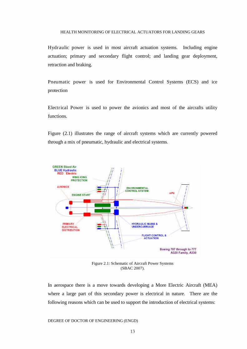
Figure (2.1) illustrates the range of aircraft systems which are currently powered
through a mix of pneumatic, hydraulic and electrical systems.
Figure 2.1: Schematic of Aircraft Power Systems(SBAC 2007).
In aerospace there is a move towards developing a More Electric Aircraft (MEA)
where a large part of this secondary power is electrical in nature. There are the
following reasons which can be used to support the introduction of electrical systems:
HEALTH MONITORING OF ELECTRICAL ACTUATORS FOR LANDING GEARS
DEGREE OF DOCTOR OF ENGINEERING (ENGD)
14
1. Reduced weight- hydraulic and bleed air systems generally contain bulky,
heavy hardware which contribute significantly to the weight of the aircraft.
2. Reduced fuel consumption - bleed air systems rely on compressed air
from the engine which is produced at the expense of fuel consumption (i.e.
fuel is consumed to produce the bleed air which then does not contribute to
engine thrust).
3. Increased efficiency - losses in hydraulic or pneumatic piping are higher
than in electrical cabling, plus these systems do not have the ability to
provide power on demand (they cannot simply be switched on and off as
required like electric systems) hence resulting in higher quiescent losses.
This means that the peak power consumption of hydraulic and bleed air
systems is higher than necessary.
4. Compromise of optimal component design - as the equipment using the bleed
air systems requires certain pressures to operate the optimal design of an
engine component may be compromised in order to provide the required air
pressure for the bleed air system (Faleiro 2005). This can lead to non-
optimal performance characteristics including fuel burn.
5. The power off-takes at the engine from all of the aircraft systems are typically
responsible for 3-5% of the total power produced by the engine (Faleiro 2005).
By developing a more electric aircraft, this power requirement can be
significantly reduced, enabling lower fuel burn and emissions.
2.3 More Electric Aircraft Research History
The concept of a complete electrically powered aircraft is not a new concept and the
considerations for military aircraft to be more electrically powered aircraft have
existed since World War 2 when debates had been begun on the best way to distribute

HEALTH MONITORING OF ELECTRICAL ACTUATORS FOR LANDING GEARS
DEGREE OF DOCTOR OF ENGINEERING (ENGD)
15
power around an aircraft. Hydraulic power systems began to rapidly develop in the
1970s and the use of electrical power onboard aircraft began to be restricted to
electronic systems only. The idea of using electric power as the only secondary power
began to gain ground with early research performed jointly by NASA and The Lewis
Research Centre (Spitzer 1984). There are two steps which are being taken to further
the MEA. The first is the removing of current air and hydraulic secondary power
supplied by the engines and increasing electrical power generation. The second is the
replacing of hydraulic and pneumatic actuators with electrical counterpart.
Different approaches including the use of electro-hydrostatic, hybrid and electro-
mechanical actuators have been considered for use as alternative actuation system for
the actuation of primary and secondary flight controls; braking; nacelle actuation and
new landing gear extension and retraction. In the past decade the use of Electro-
Hydrostatic Actuator (EHA) technology has rapidly developed and they are now
replacing hydraulic circuits on new aircraft such as the Airbus A380 and Boeing
B787.
The feasibility of using EMA was shown in research by NASA in the early 1980’s in
cooperation with Boeing Commercial Airplane Company (Holmadhl 1983). In this
research an EMA was installed on the inboard flight spoiler of a small research
aircraft. The performance of which was shown to match that of its hydraulic
counterparts. The use of EMA gained more favourable results in a second NASA
project where a large EMA was used to drive the Space Shuttle elevon (Pond and
Wyllie 1983).
The Power-By-Wire (PBW)/Fly-By-Light (FBL) research carried out by the NASA
Lewis Research Centre aimed at looking at the potentials of electric actuators in
aircraft with some specific focus on trends and tradeoffs involved in the selection of a
particular motor drive technology. In particular DC motor drives, switched reluctance
motor drives (Elbuluk and Kankam 1995) and induction drives (Elbuluk and Kankam
1996).
HEALTH MONITORING OF ELECTRICAL ACTUATORS FOR LANDING GEARS
DEGREE OF DOCTOR OF ENGINEERING (ENGD)
16
Early research into electric actuation for military aircraft included research by
Lockheed-Georgia (Bradbury 1987) into the potentials of using electric actuation for
flight controls onboard the C-130 (Alden 1991). Jensen et al. (2000) describes the test
results of an EMA fitted onto the aileron of an F/A-18. The performance of which
was shown to be virtually identical to that of a standard hydraulic actuator and
therefore validating the potential use of aileron EMAs. The tests did however
highlight problems with the actuators thermal performance.
In the early 1990s research into aircraft power systems had advanced to the stage of
replacing centralised onboard aircraft hydraulics with electrical power. This led to the
United States Air Force More Electric Aircraft program (MEA) (Cloyd 1998) which
aims at increasing a fighter aircrafts electrical capability.
There have been several DTI funded technology programmes under the Civil Aircraft
Research And technology Demonstration (CARAD) over the last decade as part of the
UK “More Electric” initiative. These programmes have helped technological
advances for electric power generation, distribution and flight surface actuation.
Example programmes include Reliable Electric ACTuation Systems (REACTS)
(Dixon et al. 1999) which investigated the use of a smart EMA which would be
suitable for use on civil gas turbine aero-engines. The Distributed Electrical Power
Management Architecture (DEPMA) (Bailey et al. 1999) consortium investigated
alternative electrical power distribution architectures on both civil and military
aircraft. In the Electric Actuated Braking SYSTem (EABSYS) (Collins 1999)
programme the aim was to design and develop an electrically actuated braking system
to replace conventional hydraulics. The Totally Integrated More Electrical Systems
(TIMES) (Cutts 2002) programme was devoted to using systems which have been
previously developed in electrical aircraft.
HEALTH MONITORING OF ELECTRICAL ACTUATORS FOR LANDING GEARS
DEGREE OF DOCTOR OF ENGINEERING (ENGD)
17
2.4 Current Relevant EU Electric Aircraft Research projects
2.4.1 Clean Sky Joint Technology Initiative
The CLEAN SKY Joint Technology Initiative is a large scale EU-wide research
programme designed to integrate and further develop the promising results of
many technology programmes currently underway. The €1.6 billion, seven year
project aims to develop the breakthrough technologies and operating practices
required for the industry to achieve the ACARE 2020 targets.
2.4.2 More Open Electrical Technologies
The More Open Electrical Technologies (MOET) project is a consortium of 46
companies and 15 research centres and universities from 14 countries in the EU. The
three year programme co-ordinated by Airbus France with a budget of around €70
million, was launched in July 2006 and aims to establish a new industrial standard
for the design of commercial aircraft electrical systems. This new standard, Power-
by-Wire (PbW) will improve aircraft design and utilisation through power source
rationalisation and electrical power flexibility.
2.4.3 Power Optimised Aircraft
The Power Optimised Aircraft (POA) is an EU programme that began in January
2002 and involved 46 partners. The €99.2 million project was led by the German
company Liebherr-Aerospace and examined novel ways of generating, distributing
and using electric power so that non-propulsive power consumption could be
minimised. Specifically, POA aimed to validate, at aircraft level, the ability
of next generation aircraft equipment systems to:
1. Reduce peak non-propulsive power by 25%
2. Reduce total non-propulsive power
3. Reduce fuel consumption by 5%
HEALTH MONITORING OF ELECTRICAL ACTUATORS FOR LANDING GEARS
DEGREE OF DOCTOR OF ENGINEERING (ENGD)
18
4. Reduce total equipment weight
2.4.4 Electric Landing Gear Extension and Retraction (ELGEAR)
This DTI funded technology programme began in 2006 with a consortium consisting
of four major partners, Airbus, Smiths Aerospace, Goodrich Actuation Services and
Messier-Dowty. This aims of which are to design and model a complex system for
control and actuation of an all electric landing gear system for the future replacements
to single aisle aircraft such as those in the size range of the Airbus A320 and Boeings
B737.
2.5 Overview of Landing Gears
Landing gears are an essential part of the aircraft even though they remain redundant
for most of the flight. The main task of the landing gear is to absorb the horizontal
and vertical energy of the touchdown as well as ensuring a smooth ride before takeoff.
Jenkins (1985) and Young (1986) have published overviews of landing gear design
with text books such as Conway (1958) and Currey (1988) giving in depth details on
landing gear development.
Most modern transport aircraft are designed with retractable landing gears positioned
in a tricycle configuration with a nose gear and two main gears. Conventional
tricycle configured landing gears have become the best solution to taxiing, taking off
and landing with unconventional designs such as skids or air cushion landing gears
being reserved for special applications. Landing gears must be positioned relative to
the aircrafts centre of gravity to prevent them from being easily overturned or from
tipping back onto its tail under static and dynamic loads. The geometry of the
landing gears must also provide clearance of the aircraft with the ground during all
operational conditions. During flight most modern aircraft have their landing gears
retracted and stowed. A prime task for the design of landing gears is to minimise the
volume of the stowed gears and provide the lowest weight possible. This can pose
restrictions on the positioning of the gears with the volume and installed weight
having adverse effects on the performance of the aircraft.

HEALTH MONITORING OF ELECTRICAL ACTUATORS FOR LANDING GEARS
DEGREE OF DOCTOR OF ENGINEERING (ENGD)
19
Landing gear occupy significant amounts of volume and accounts for about 3% of the
overall mass on military aircraft and about 4% on civil aircraft. In landing gear
design there is a continued effort to reduce this mass through development of new
materials with advanced design and manufacturing techniques allowing for
optimization of aircraft mass (Jenkins 1989). At the heart of the landing gear unit is
the shock absorber. This is designed to absorb the energy generated by the impact
between the gears and the runway upon landing. There are many different types of
shock absorber construction. The most popular is as an oleo-pneumatic shock strut
which combines a gas spring with oil and additional friction damping
The landing gear brakes are required to bring the aircraft to a halt and to help control
the aircraft as it taxis to the runway. The design of the brakes must be able to support
very high temperatures. The brakes add substantial mass to the landing gears and are
generally fixed to the main gears only. As an example the brakes make up 24% of the
total 3626kg mass of the AIRBUS A300 main landing gears (Kruger et al. 1997). The
temperature of the brakes must be monitored as take off cannot be carried out if the
brakes are hot. The reasons for this are that there is a risk of fire if the high
temperatures on the brakes come into contact with hydraulic fluid in the land gear bay.
The number and size of the aircraft tyres is an important design consideration and is
dictated by the aircrafts weight and the strength of the runway which will vary
depending on the airport. Larger civil aircraft such as the A320 and Boeing 747 reach
loads of 20 tons per tyre on each of the main gears (Krüger 2000).
In order to retract landing gears into the smallest possible space, complex motions are
required which will put the landing gear into the assigned space without colliding with
other structures. The main methods of retracting landing gear include mechanical
drives such as pneumatic, hydraulic and electrical actuation. The landing gear
retraction geometry is effectively dependent upon the position of the lowered wheels
(which is governed by ground stability, load distribution and clearance angles),
HEALTH MONITORING OF ELECTRICAL ACTUATORS FOR LANDING GEARS
DEGREE OF DOCTOR OF ENGINEERING (ENGD)
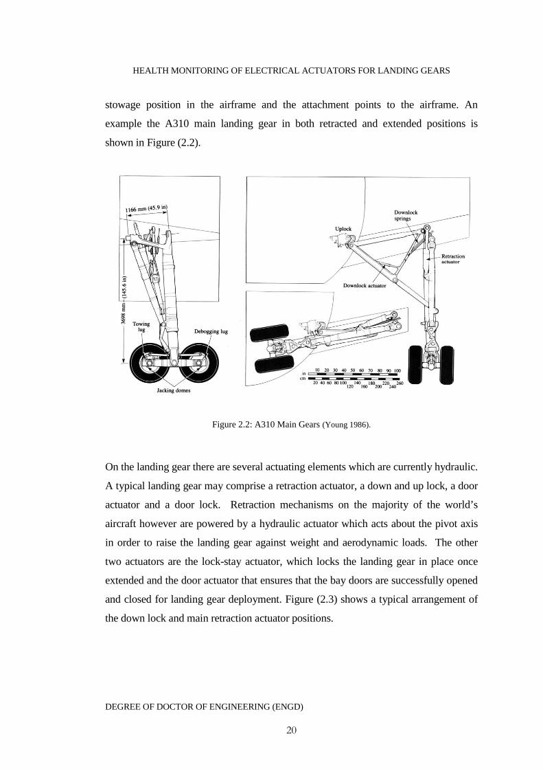
20
stowage position in the airframe and the attachment points to the airframe. An
example the A310 main landing gear in both retracted and extended positions is
shown in Figure (2.2).
Figure 2.2: A310 Main Gears (Young 1986).
On the landing gear there are several actuating elements which are currently hydraulic.
A typical landing gear may comprise a retraction actuator, a down and up lock, a door
actuator and a door lock. Retraction mechanisms on the majority of the world’s
aircraft however are powered by a hydraulic actuator which acts about the pivot axis
in order to raise the landing gear against weight and aerodynamic loads. The other
two actuators are the lock-stay actuator, which locks the landing gear in place once
extended and the door actuator that ensures that the bay doors are successfully opened
and closed for landing gear deployment. Figure (2.3) shows a typical arrangement of
the down lock and main retraction actuator positions.

HEALTH MONITORING OF ELECTRICAL ACTUATORS FOR LANDING GEARS
DEGREE OF DOCTOR OF ENGINEERING (ENGD)
21
Figure 2.3 Airbus A320 Main Gears
General future requirements for aircraft landing gear include (i) longer life, (ii) lower
mass/volume and (iii) lower support costs. Longer life and lower support costs can be
met through the use of advanced maintenance such as a future prognostic/diagnostic
health monitoring system.
2.6 Actuator Types
Historically there have been numerous difficulties associated with using electrically
powered actuators in aircraft (Wijekoon 2009). These have attributed directly to the
many reasons why hydraulics dominate actuation in aircraft and have done for a
number of decades. The extensive use of hydraulics by aircraft constructors has led to
wide experience with hydraulics and familiarity with their pros and cons. The wide
use of hydraulic systems immediately indicates a reliable and safe system, creating
confidence in the systems. The most serious criticisms of hydraulics are the potential
fire risk from inflammable hydraulic fluids and their general messiness. The
worldwide use of hydraulic equipment has created an extensive and specialised
industry. Through competitive effort a high level of technical design and production
HEALTH MONITORING OF ELECTRICAL ACTUATORS FOR LANDING GEARS
DEGREE OF DOCTOR OF ENGINEERING (ENGD)
22
and supply chains have been achieved. Since hydraulics has set the pace competitive
systems lag behind in the solution to certain actuation problems.
Hydraulic equipment is naturally adequately lubricated by the operating fluid this is
not the case with a pneumatic or electric systems. Here the piston seals are lubricated
with grease which can become solid at low temperatures meaning that maintaining an
adequate film of grease at all times is difficult. However the need to reduce aircraft
frame noise and aircraft weight has led to alternative electrical actuation being
considered as permanent replacements to hydraulics. Electrical actuators operate
much quieter than hydraulic cylinders and also have the potential to reduce mass and
overall volume of the system. Electrical actuation units are however often heavier
than hydraulic cylinders but hydraulic system consists of a number of individual
additional components connected by piping which can require a large space whilst
electric systems use much smaller wires. It is therefore predicted that the removal of
the overall hydraulic systems will result in a beneficial weight reduction. This
reduction in landing gear weight will help reduce the consumption of fuel and hence a
reduction in polluting emissions.
The use of electrical actuators also offers potential maintenance savings and
production costs. They run more efficiently than hydraulic cylinders at low ambient
temperatures, low temperatures tend to cause hydraulic fluid to become more viscous
making the operation of the cylinders sluggish. The most important reason however
for investigating replacement of hydraulic actuation is to optimise engine power.
Actuation is regarded as secondary power systems, the power for which is generated
within the engines. Increases in airline fuel taxes make it desirable to optimise engine
power usage. Electrical actuation will aid in reducing this dependency on power
generated from the engines reducing fuel costs. There is also a distinct and real
possibility that future aircraft engines will not produce hydraulic power.
When deciding whether to use electromechanical actuators in a particular application
the sole deciding factors are: which actuator type best meets the technical and
HEALTH MONITORING OF ELECTRICAL ACTUATORS FOR LANDING GEARS
DEGREE OF DOCTOR OF ENGINEERING (ENGD)
23
economic demands of the application. There are three main types of linear actuation,
which operate either by a lead, roller or ball screw.
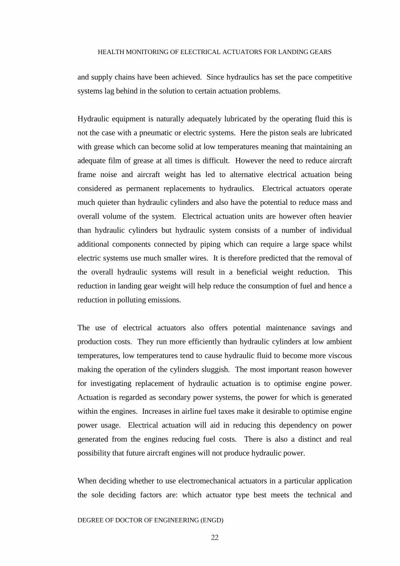
2.6.1 Lead Screw
The basic leadscrew illustrated in Figure (2.4) assembly is a simple nut and screw
mating with rubbing surfaces. Consequently they have a relatively high friction and
stiction compared to mechanical parts which mate with rolling surfaces and bearings
(i.e. roller and ball screws).
Figure 2.4: Example of a Lead Screw Assembly*
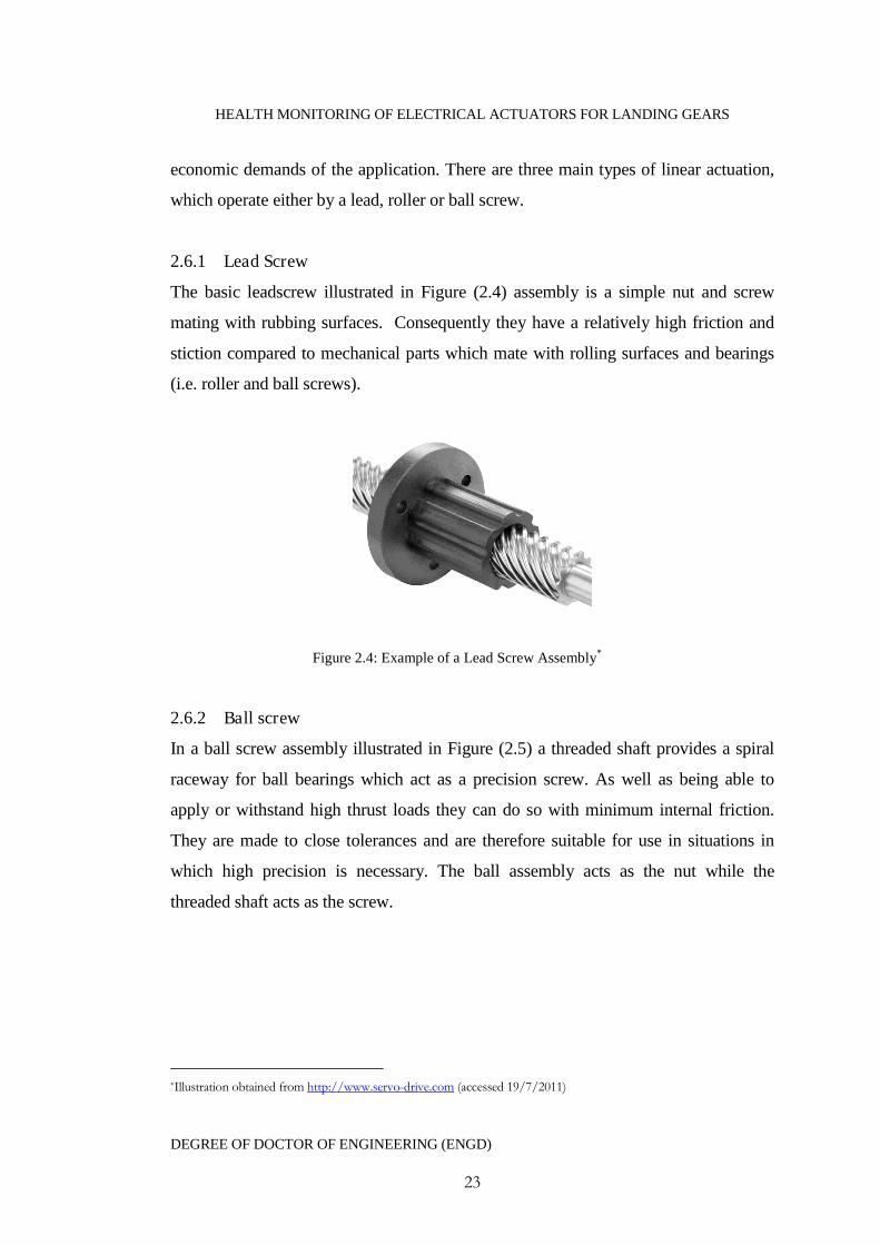
2.6.2 Ball screw
In a ball screw assembly illustrated in Figure (2.5) a threaded shaft provides a spiral
raceway for ball bearings which act as a precision screw. As well as being able to
apply or withstand high thrust loads they can do so with minimum internal friction.
They are made to close tolerances and are therefore suitable for use in situations in
which high precision is necessary. The ball assembly acts as the nut while the
threaded shaft acts as the screw.
*Illustration obtained from http://www.servo-drive.com (accessed 19/7/2011)
HEALTH MONITORING OF ELECTRICAL ACTUATORS FOR LANDING GEARS
DEGREE OF DOCTOR OF ENGINEERING (ENGD)
24
Figure 2.5: Example of a Ball Screw Assembly*
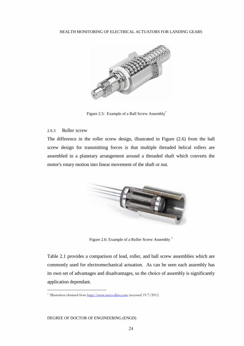
2.6.3 Roller screw
The difference in the roller screw design, illustrated in Figure (2.6) from the ball
screw design for transmitting forces is that multiple threaded helical rollers are
assembled in a planetary arrangement around a threaded shaft which converts the
motor's rotary motion into linear movement of the shaft or nut.
Figure 2.6: Example of a Roller Screw Assembly †
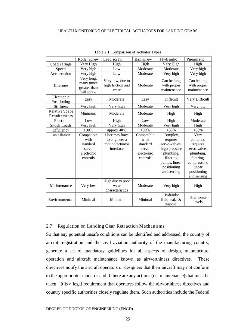
Table 2.1 provides a comparison of lead, roller, and ball screw assemblies which are
commonly used for electromechanical actuation. As can be seen each assembly has
its own set of advantages and disadvantages, so the choice of assembly is significantly
application dependant.
* *Illustration obtained from http://www.servo-drive.com (accessed 19/7/2011)
HEALTH MONITORING OF ELECTRICAL ACTUATORS FOR LANDING GEARS
DEGREE OF DOCTOR OF ENGINEERING (ENGD)
25
Table 2.1: Comparison of Actuator Types
Roller screw Lead screw Ball screw Hydraulic PneumaticLoad ratings Very High High High Very High High
Speed Very high Low Moderate Moderate Very highAcceleration Very high Low Moderate Very high Very high
Lifetime
Very long,many timesgreater thanball screw
Very low, due tohigh friction and
wearModerate
Can be longwith propermaintenance
Can be longwith propermaintenance
ElectronicPositioning
Easy Moderate Easy Difficult Very Difficult
Stiffness Very high Very high Moderate Very high Very lowRelative SpaceRequirements
Minimum Moderate Moderate High High
Friction Low High Low High ModerateShock Loads Very high Very high Moderate Very high High
Efficiency >90% approx 40% >90% <50% <50%Installation Compatible
withstandard
servoelectroniccontrols
User may haveto engineer a
motion/actuatorinterface
Compatiblewith
standardservo
electroniccontrols
Complex,requires
servo-valves,high pressure
plumbing,filtering
pumps, linearpositioningand sensing
Verycomplex,requires
servo-valves,plumbing,filtering,
compressors,linear
positioningand sensing
Maintenance Very lowHigh due to poor
wearcharacteristics
Moderate Very high High
Environmental Minimal Minimal MinimalHydraulic
fluid leaks &disposal
High noiselevels
2.7 Regulation on Landing Gear Retraction Mechanisms
So that any potential unsafe conditions can be identified and addressed, the country of
aircraft registration and the civil aviation authority of the manufacturing country,
generate a set of mandatory guidelines for all aspects of design, manufacture,
operation and aircraft maintenance known as airworthiness directives. These
directives notify the aircraft operators or designers that their aircraft may not conform
to the appropriate standards and if there are any actions (i.e. maintenance) that must be
taken. It is a legal requirement that operators follow the airworthiness directives and
country specific authorities closely regulate them. Such authorities include the Federal

HEALTH MONITORING OF ELECTRICAL ACTUATORS FOR LANDING GEARS
DEGREE OF DOCTOR OF ENGINEERING (ENGD)
26
Aviation Administration (USA), The Civil Aviation Safety Authority (Australia) and
The Joint Aviation Authorities (Europe).For aircraft with retractable landing gear, the
following common directives apply:
Each landing gear retracting mechanism and its supporting structure must be
designed for maximum flight load factors with the gear retracted. They must
be designed to handle the combination of friction, inertia, brake torque, and air
loads, occurring during retraction at any airspeed up to 1.6 V with flaps
retracted.
The landing gear and retracting mechanism, including the wheel doors, must
withstand flight loads, including loads resulting from all yawing conditions
with the landing gear extended at any speed up to at least 1.6 V with the flaps
retracted.
There must be positive means (other than the use of hydraulic pressure) to
keep the landing gear extended
For a landplane having retractable landing gear that cannot be extended
manually, there must be means to extend the landing gear in the event of
either:
1. Any reasonably probable failure in the normal landing gear
operation system;
2. Any reasonably probable failure in a power source that would
prevent the operation of the normal landing gear operation system.
If a retractable landing gear is used, there must be a landing gear position
indicator (as well as necessary switches to actuate the indicator) or other
means to inform the pilot that each gear is secured in the extended or retracted
positions.
HEALTH MONITORING OF ELECTRICAL ACTUATORS FOR LANDING GEARS
DEGREE OF DOCTOR OF ENGINEERING (ENGD)
27
2.8 Messier Dowty Actuator Design
The actuator designs for the retraction and lock-stay actuators currently under
development by Messier-Dowty Ltd for use on the aircrafts main gears is based
around that of a roller screw. The other possible consideration was a ball screw
assembly, but with the roller screws ability to handle larger shock loads, reduced
friction, smaller space requirements, easy control and longer lifespan; the roller screw
has been selected as the most appropriate arrangement to meet the specific landing
gear requirement.
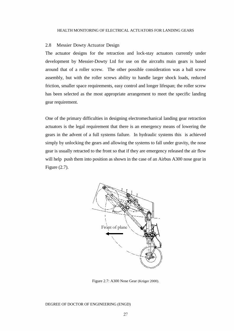
One of the primary difficulties in designing electromechanical landing gear retraction
actuators is the legal requirement that there is an emergency means of lowering the
gears in the advent of a full systems failure. In hydraulic systems this is achieved
simply by unlocking the gears and allowing the systems to fall under gravity, the nose
gear is usually retracted to the front so that if they are emergency released the air flow
will help push them into position as shown in the case of an Airbus A300 nose gear in
Figure (2.7).
Figure 2.7: A300 Nose Gear (Krüger 2000).
Front of plane
HEALTH MONITORING OF ELECTRICAL ACTUATORS FOR LANDING GEARS
DEGREE OF DOCTOR OF ENGINEERING (ENGD)
28
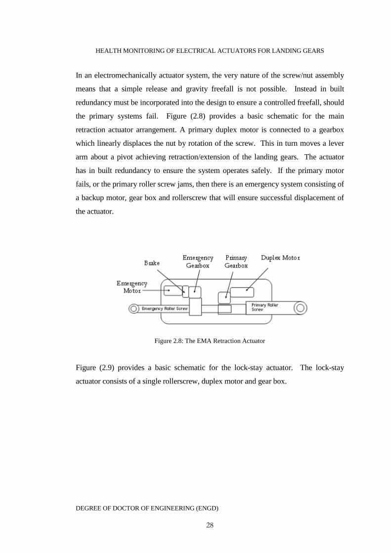
In an electromechanically actuator system, the very nature of the screw/nut assembly
means that a simple release and gravity freefall is not possible. Instead in built
redundancy must be incorporated into the design to ensure a controlled freefall, should
the primary systems fail. Figure (2.8) provides a basic schematic for the main
retraction actuator arrangement. A primary duplex motor is connected to a gearbox
which linearly displaces the nut by rotation of the screw. This in turn moves a lever
arm about a pivot achieving retraction/extension of the landing gears. The actuator
has in built redundancy to ensure the system operates safely. If the primary motor
fails, or the primary roller screw jams, then there is an emergency system consisting of
a backup motor, gear box and rollerscrew that will ensure successful displacement of
the actuator.
Figure 2.8: The EMA Retraction Actuator
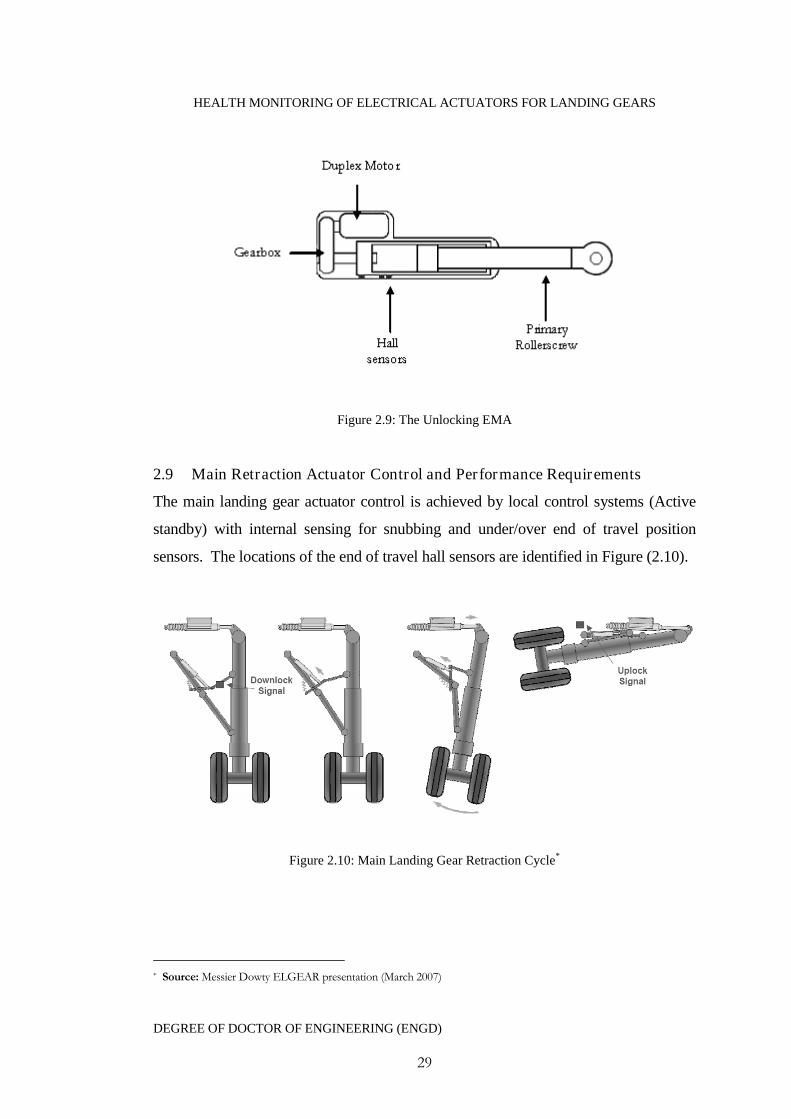
Figure (2.9) provides a basic schematic for the lock-stay actuator. The lock-stay
actuator consists of a single rollerscrew, duplex motor and gear box.
HEALTH MONITORING OF ELECTRICAL ACTUATORS FOR LANDING GEARS
DEGREE OF DOCTOR OF ENGINEERING (ENGD)
29
Figure 2.9: The Unlocking EMA
2.9 Main Retraction Actuator Control and Performance Requirements
The main landing gear actuator control is achieved by local control systems (Active
standby) with internal sensing for snubbing and under/over end of travel position
sensors. The locations of the end of travel hall sensors are identified in Figure (2.10).
Figure 2.10: Main Landing Gear Retraction Cycle*
* Source: Messier Dowty ELGEAR presentation (March 2007)
HEALTH MONITORING OF ELECTRICAL ACTUATORS FOR LANDING GEARS
DEGREE OF DOCTOR OF ENGINEERING (ENGD)
30
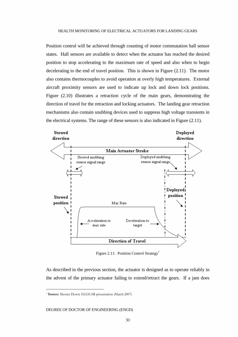
Position control will be achieved through counting of motor commutation hall sensor
states. Hall sensors are available to detect when the actuator has reached the desired
position to stop accelerating to the maximum rate of speed and also when to begin
decelerating to the end of travel position. This is shown in Figure (2.11). The motor
also contains thermocouples to avoid operation at overly high temperatures. External
aircraft proximity sensors are used to indicate up lock and down lock positions.
Figure (2.10) illustrates a retraction cycle of the main gears, demonstrating the
direction of travel for the retraction and locking actuators. The landing gear retraction
mechanisms also contain snubbing devices used to suppress high voltage transients in
the electrical systems. The range of these sensors is also indicated in Figure (2.11).
Figure 2.11: Position Control Strategy*
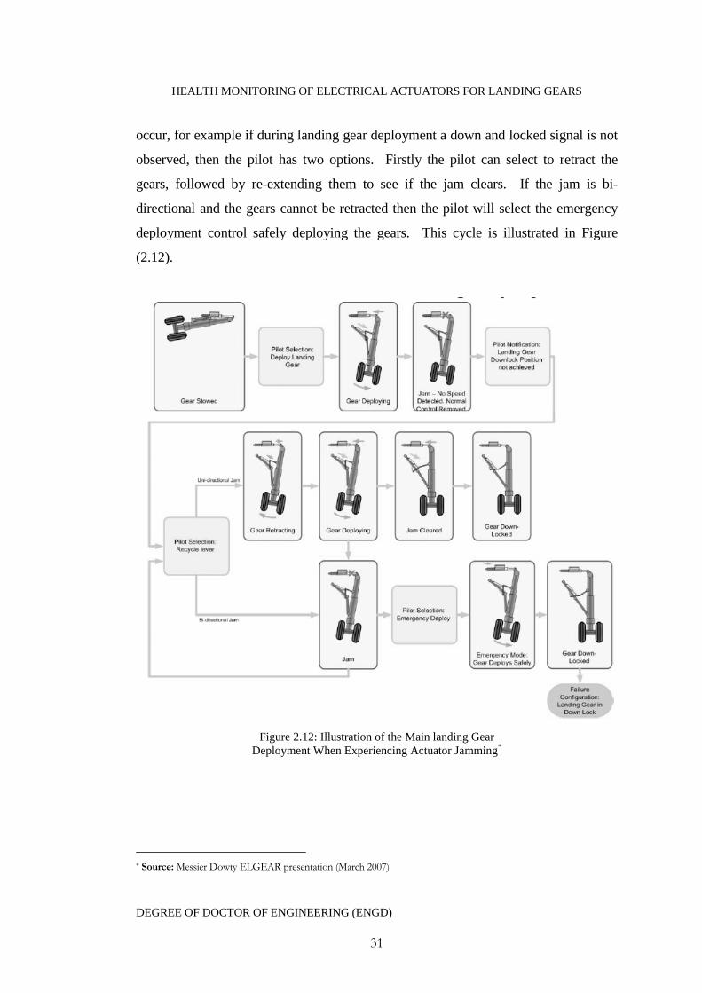
As described in the previous section, the actuator is designed as to operate reliably in
the advent of the primary actuator failing to extend/retract the gears. If a jam does
* Source: Messier Dowty ELGEAR presentation (March 2007)
HEALTH MONITORING OF ELECTRICAL ACTUATORS FOR LANDING GEARS
DEGREE OF DOCTOR OF ENGINEERING (ENGD)
31
occur, for example if during landing gear deployment a down and locked signal is not
observed, then the pilot has two options. Firstly the pilot can select to retract the
gears, followed by re-extending them to see if the jam clears. If the jam is bi-
directional and the gears cannot be retracted then the pilot will select the emergency
deployment control safely deploying the gears. This cycle is illustrated in Figure
(2.12).
Figure 2.12: Illustration of the Main landing GearDeployment When Experiencing Actuator Jamming*
* Source: Messier Dowty ELGEAR presentation (March 2007)
HEALTH MONITORING OF ELECTRICAL ACTUATORS FOR LANDING GEARS
DEGREE OF DOCTOR OF ENGINEERING (ENGD)
32
2.10 Reliability and Safety issues
Landing gear actuators are primarily mechanical/electrical systems with moving parts
and as with all mechanical/electrical systems they are subject to failure. The design of
the actuator therefore must be designed sufficiently robust as to maximise the
probability that it will perform satisfactory for a specific period of time under
specified conditions. The main failure modes which are of primary concerns are as
follows.
1. Failure to retract/extend the landing gear in the systems normal operating
mode.
2. Failure to damp the landing gear at the end of the retraction/extension cycle in
the systems normal operating mode.
3. Inadvertent retraction/extension.
4. Slow or jerky retraction.
5. Failure to permit the full extension of the landing gear in the freefall mode.
6. Failure to damp the landing gear at the end of the extension in the freefall
mode.
If any of these modes occur then it can be deemed that the actuator system is “lost”.
This means that it can no longer perform satisfactory and is unsafe to fly the aircraft
until rectified. In order to avoid these failure modes than the system must be designed
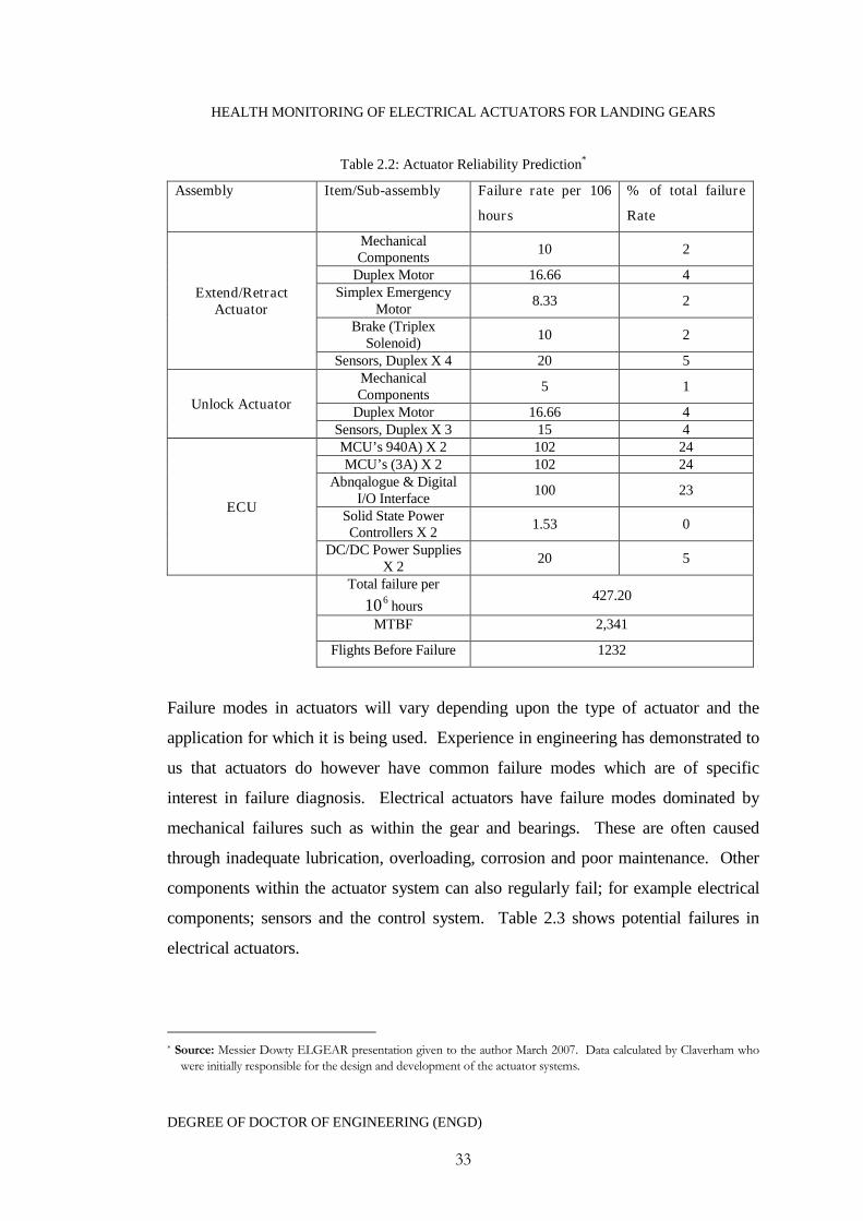
to meet specific reliability criteria. Table 2.2 gives an example of the actuator
reliability prediction as calculated during the early stages of development. This
reliability prediction is estimated based upon standard material components. The use
of aerospace grade materials and components however is likely to significantly
increase the reliability of the actuator system.
HEALTH MONITORING OF ELECTRICAL ACTUATORS FOR LANDING GEARS
DEGREE OF DOCTOR OF ENGINEERING (ENGD)
33
Table 2.2: Actuator Reliability Prediction*
Assembly Item/Sub-assembly Failure rate per 106
hours
% of total failure
Rate
Extend/RetractActuator
MechanicalComponents
10 2
Duplex Motor 16.66 4Simplex Emergency
Motor8.33 2
Brake (TriplexSolenoid)
10 2
Sensors, Duplex X 4 20 5
Unlock Actuator
MechanicalComponents
5 1
Duplex Motor 16.66 4Sensors, Duplex X 3 15 4
ECU
MCU’s 940A) X 2 102 24MCU’s (3A) X 2 102 24
Abnqalogue & DigitalI/O Interface
100 23
Solid State PowerControllers X 2
1.53 0
DC/DC Power SuppliesX 2
20 5
Total failure per610 hours
427.20
MTBF 2,341
Flights Before Failure 1232
Failure modes in actuators will vary depending upon the type of actuator and the
application for which it is being used. Experience in engineering has demonstrated to
us that actuators do however have common failure modes which are of specific
interest in failure diagnosis. Electrical actuators have failure modes dominated by
mechanical failures such as within the gear and bearings. These are often caused
through inadequate lubrication, overloading, corrosion and poor maintenance. Other
components within the actuator system can also regularly fail; for example electrical
components; sensors and the control system. Table 2.3 shows potential failures in
electrical actuators.
* Source: Messier Dowty ELGEAR presentation given to the author March 2007. Data calculated by Claverham whowere initially responsible for the design and development of the actuator systems.
HEALTH MONITORING OF ELECTRICAL ACTUATORS FOR LANDING GEARS
DEGREE OF DOCTOR OF ENGINEERING (ENGD)
34
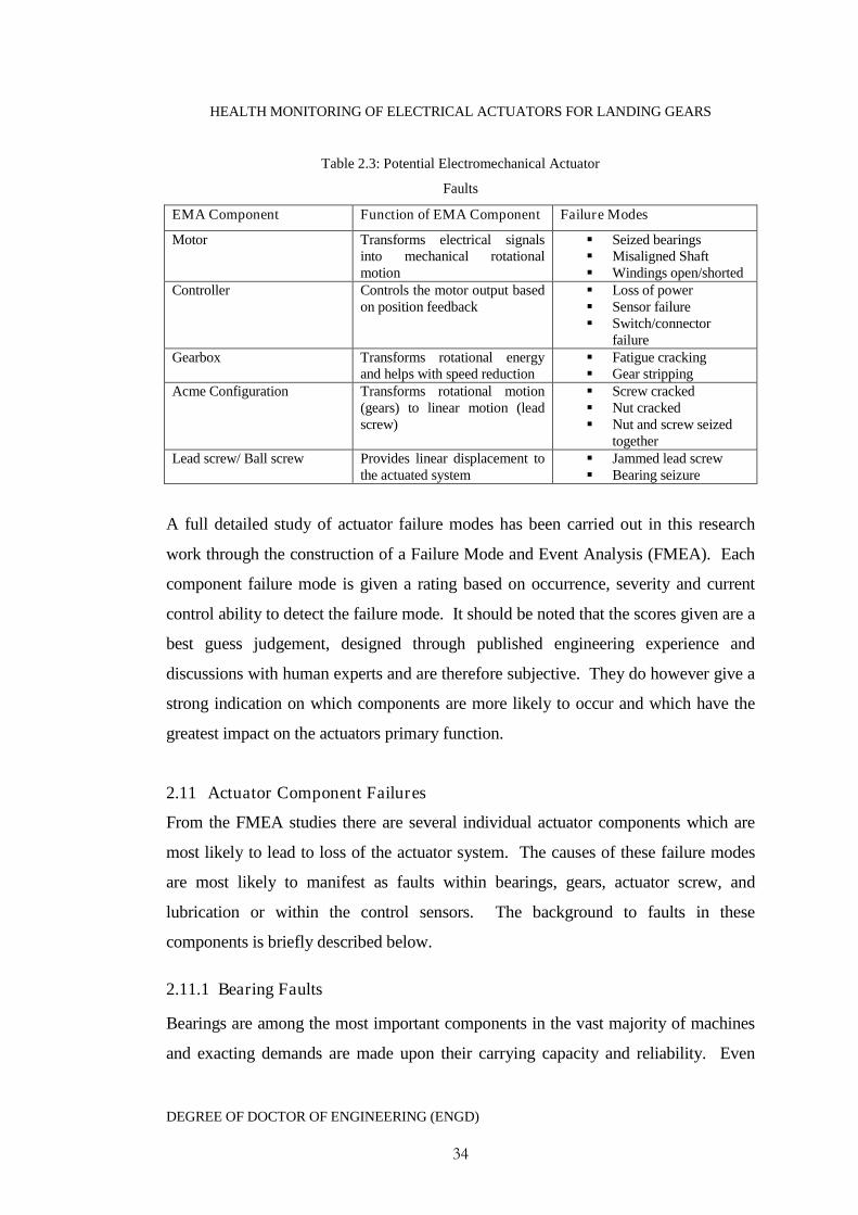
Table 2.3: Potential Electromechanical Actuator
Faults
EMA Component Function of EMA Component Failure Modes
Motor Transforms electrical signalsinto mechanical rotationalmotion
Seized bearings Misaligned Shaft Windings open/shorted
Controller Controls the motor output basedon position feedback
Loss of power Sensor failure Switch/connector
failureGearbox Transforms rotational energy
and helps with speed reduction Fatigue cracking Gear stripping
Acme Configuration Transforms rotational motion(gears) to linear motion (leadscrew)
Screw cracked Nut cracked Nut and screw seized
togetherLead screw/ Ball screw Provides linear displacement to
the actuated system Jammed lead screw Bearing seizure
A full detailed study of actuator failure modes has been carried out in this research
work through the construction of a Failure Mode and Event Analysis (FMEA). Each
component failure mode is given a rating based on occurrence, severity and current
control ability to detect the failure mode. It should be noted that the scores given are a
best guess judgement, designed through published engineering experience and
discussions with human experts and are therefore subjective. They do however give a
strong indication on which components are more likely to occur and which have the
greatest impact on the actuators primary function.
2.11 Actuator Component Failures
From the FMEA studies there are several individual actuator components which are
most likely to lead to loss of the actuator system. The causes of these failure modes
are most likely to manifest as faults within bearings, gears, actuator screw, and
lubrication or within the control sensors. The background to faults in these
components is briefly described below.
2.11.1 Bearing Faults
Bearings are among the most important components in the vast majority of machines
and exacting demands are made upon their carrying capacity and reliability. Even
HEALTH MONITORING OF ELECTRICAL ACTUATORS FOR LANDING GEARS
DEGREE OF DOCTOR OF ENGINEERING (ENGD)
35
though bearings are precision engineered to operate reliability for a certain calculated
useful life it sometimes happens that they do not attain to this calculated rating and
can fail. There are many reasons for this such as heavier than usual loading,
inadequate/unsuitable lubrication, ineffective sealing or poor installation. Each of
these factors creates its own damage type within the bearing, categorised as the
primary damage including wear, indentations, smearing, surface distress and
corrosion. This can then lead onto secondary damage resulting in metallic flaking and
cracks. Damaged bearings will affect the smooth running of the actuator creating
jerks within the motion and if left unmaintained they will eventually seize leading to
the total loss of the actuator system.
2.11.2 Gear Faults
Metal gears fail for numerous reasons, some, in part, independent from the gears
themselves. Assessing gear damage can be a challenge, especially in industrial
equipment. Unlike lab tests designed to isolate a particular failure mode, field failures
may combine several modes. The more common failures include bending fatigue
failure, which is the result of cyclic bending stress at the tooth root. The damage
process follows three stages: crack nucleation, crack propagation, and final unstable
fracture. Pitting or macropitting is surface damage from cyclic contact stress
transmitted through a lubrication film that is in or near the elastohydrodynamic
regime. Pitting is one of the most common causes of gear failure. Scuffing, also
termed is a severe type of adhesive wear which instantly damages tooth surfaces that
are in relative motion. In fact, a single overload can lead to catastrophic failure. Wear
is a continuous, abrasive process of material removal from mating gear teeth that
happens with or without abrasive particles in the oil. For example, hard asperities on
gear flanks can remove material from mating flanks. Removal of the hardened layer
from surface-hardened gears accelerates wear.
2.11.3 Roller Screw Failure
Roller screws, in contrast to conventional lead screws tend to much bulkier due to the
need to have a mechanism for recirculation of the balls. To maintain the inherent
HEALTH MONITORING OF ELECTRICAL ACTUATORS FOR LANDING GEARS
DEGREE OF DOCTOR OF ENGINEERING (ENGD)
36
accuracy associated with a roller screw and too ensure minimal risk of failure great
care is needed to avoid contamination with dirt and abrasive particles. For instance, if
metal chips get into the nut assembly, the roller screws may grind them into a lapping
compound, which will cause spalling and eventual catastrophic failure. The result of
such contamination will lead to rapid degradation of the screws lubrication fluids,
increasing friction resulting in higher than normal loading and inevitable wearing of
the screw thread along with potential seizure of the roller assembly. Also, the
inadequate use of the correct lubricant to protect the assembly from heat build up,
caused through natural friction between mating metal surfaces will also lead to a
similar failure result. Improper loading is another possible cause of roller screw
failure. As a general rule, screws do not tolerate applied moments or side loading,
which can be caused through incorrect installation and may result in the warping of
the threaded screw further increasing the side loading.
2.12 Conclusion
For over 60 years the aerospace industry has been dominated by the use of hydraulic
and pneumatic drives with electrical drives being reserved for low power and load
applications on small light aircraft. The pneumatic and hydraulic power for these
drives originates as secondary engine power and therefore has a direct impact upon
the aircrafts fuel consumption and polluting emissions. With advances in electrical
power generation technology research across the aerospace sector has begun to seek to
reduce dependence of engine generated hydraulic secondary power for actuation
systems and more towards electrical powered systems. This has led to many advances
in electromechanical actuation technology for aerospace applications such as primary
flight control surfaces, engine actuation, cargo doors and landing gear retraction
mechanisms.
The issues with replacing hydraulic actuators with electromechanically counterparts
are mainly related to reliability. The actuators which are under development by
Messier Dowty utilise technology which is unproven in a landing gear application for
medium to large aircraft. They therefore have to be engineered to include redundancy
HEALTH MONITORING OF ELECTRICAL ACTUATORS FOR LANDING GEARS
DEGREE OF DOCTOR OF ENGINEERING (ENGD)
37
ensuring that they are robust enough to operate in the extreme environment of the
landing gear bay and are reliable enough to ensure successful operation.
The main concerns of actuator failure are mechanical jamming. There are a variety of
underlying faults which can increase in severity and lead to actuator jamming. These
have been identified through a Failure Mode Event Analysis of an actuator system as
bearing damage, gear seizure or physical actuator screw damage. Through the
elicitation of expert knowledge during the course of studying the actuator system, the
primary and most common cause for each of these failures begins with the
degradation of the lubrication system. It is therefore considered that in order to detect
incipient faults as early as possible, for this application the ability to detect changes to
the lubrication within the actuator system is of paramount importance.
The use of aerospace grade components can increase the reliability of individual
actuator components but failures will still inevitably occur. Further health monitoring
systems incorporated into the actuator system would offer the potential to increase this
reliability even further. This would aid in justifying the need for additional automated
fault detection and diagnostic health monitoring systems but the choice of acceptable
approaches will be limited through design restrictions, regulation and costs.
2.13 References
Alden, R. ‘C-141 and C-130 power-by-wire flight control systems’, (1991) Aerospace
and Electronics Conference: NAECON, Dayton, OH , USA
Bailey, M., Hale, N., Ucerpi, G., Hunt, J-A., Mollov, S., Forsyth, A. (1999),Distributed electrical power management architecture', IEEE Colloquium onElectrical Machines and Systems for the More Electric Aircraft, London, UK
Bradbury, G. 'Development of an advanced primary flight control electromechanical
actuator', (1987), Dayton, OH, USA: IEEE, New York, NY, USA.

HEALTH MONITORING OF ELECTRICAL ACTUATORS FOR LANDING GEARS
DEGREE OF DOCTOR OF ENGINEERING (ENGD)
38
Cloyd, J. (1998), 'Status of the United States Air Force's more electric aircraft
initiative', IEEE Aerospace and Electronic Systems Magazine, Vol 13, No 4, pp. 17-
22.
Collins, A. (1999), 'EABSYS: electrically actuated braking system'. IEE Colloquium
on Electrical Machines and Systems for the More Electric Aircraft, London, UK: IEE.
Conway, H.G., (1958), 'Landing gear design', The Royal Aeronautical Society.
Cutts, S.J. (2002), 'A collaborative approach to the more electric aircraft',
International Conference on Power Electronics, Machines and Drives, Bath, UK
Currey, N., (1998), 'Aircraft landing gear design: principles and practices', AIAA.
Dixon, R., Gifford, N., Sewell, C., Spalton, M. (1999), 'REACTS: Reliable electrical
actuation systems', IEE Colloquium: Electrical Machines and Systems for the More
Electric Aircraft, Vol 1999, No 180, pp. 23-38.
Elbuluk, M., Kankam, M. (1995a), 'Motor drive technologies for the power-by-wire
(PBW) program: options, trends and tradeoffs', Aerospace and Electronics
Conference, NAECON,
Elbuluk, M., Kankam, M. (1995b), 'Motor drive technologies for the power-by-wire
(PBW) program: options, trends and tradeoffs. I. Motors and controllers', Aerospace
and Electronic Systems Magazine, IEEE, Vol 10, No 11, pp 37-42
Faleiro, L. (2005), 'Beyond the more electric aircraft' Aerospace America,
Holmdahl, M. (1983), 'Putting new all electric technology development to the test',
NAECON, Dayton, OH, USA,

HEALTH MONITORING OF ELECTRICAL ACTUATORS FOR LANDING GEARS
DEGREE OF DOCTOR OF ENGINEERING (ENGD)
39
Jenkins, S. (1989), 'Landing gear design and development', Proceedings of the
Institution of Mechanical Engineers, Vol 203, No G1/1989, pp. 67-73
Jensen, S., Raymond, B., Dawson, D. (2000), 'Flight test experience with an
electromechanical actuator on the F-18 systems research aircraft', The 19th
Proceedings on Digital Avionics Systems Conferences, IEEE, Philadelphia, PA, USA
Krüger, W., Besselink, I., Cowling, D., Boan, D., Kortüm, W., Krabacher, W. (1997),
'Aircraft Landing Gear Dynamics: Simulation and Control', Vehicle System Dynamics,
Vol 28, No 2, pp. 119-158.
Krüger, W., (2000), 'Integrated design process for the development of semi-active
landing gears for transport aircraft', Doctorate Thesis
Pond, C,. Wyllie, C. (1983), 'Test results of a unique high power electric motor
actuator designed for space shuttle applications', IEEE
SBAC. (2007), 'Aircraft and environmental briefing papers', Aircraft Technology and
Emissions
Spitzer, C,. (1984), 'The all-electric aircraft: a systems view and proposed NASA
research programs', IEEE: Transactions on Aerospace and Electronic Systems,
Dayton, OH, USA.
Wijekoon, L., Wheeler, P., Clare, J., Whitley, C., Towers, G. (2009), 'Aircraft
electrical landing gear actuation using dual-output power converter with mutual power
circuit components', The 24th IEEE Applied Power Electronics Conference and
Exposition, Washington, DC, USA

HEALTH MONITORING OF ELECTRICAL ACTUATORS FOR LANDING GEARS
DEGREE OF DOCTOR OF ENGINEERING (ENGD)
40
Young, D. (1986), 'Aircraft landing gears - The past, present and future', Proceedings
of the Institution of Mechanical Engineers, Part D: Transport Engineering, Vol 200,
No D2, pp. 75-92.
HEALTH MONITORING OF ELECTRICAL ACTUATORS FOR LANDING GEARS
DEGREE OF DOCTOR OF ENGINEERING (ENGD)
41
C h a p t e r 3 : C o n d i t i o n B a s e d M a i n t e n a n c e f o rE n g i n e e r i n g S y s t e m s
3.1 Introduction
This chapter presents a general review within the area of engineering Condition Based
Maintenance (CBM) and related topics. The review covers a wide range of literature
including general methodologies, design guidelines, open systems architectural
frameworks, sensor systems, feature selection and health assessment strategies. An
industry wide review of the subject area applied to actuation systems is provided
along with critical reviews of the main fault diagnosis techniques and strategies, in the
context of aerospace electromechanical actuator health monitoring (Phillips et al.
2008).
There are several conventional maintenance strategies which are aimed at
safeguarding against sudden machine breakdowns. These include Run-to-Failure
(RTF), Time-Based Preventative Maintenance (TBPM) and Condition Based
Maintenance (CBM), each of which is described below:
1. Run-to-Failure Maintenance (RTF) is a method which allows any maintenance
action to be postponed until an actual machine breakdown occurs. This has the
advantage of requiring less planning and scheduling of maintenance activities.
RTF maintenance is at its most effective when the cost of a breakdown and risk to
human or environmental safety is negligible. Reliance upon RTF practice can lead
to unexpected and costly machine breakdowns. There is the possibility of
inexpensive component faults leading to further costly damage to other machine
systems. RTF maintenance also has a large requirement on maintenance
personnel and spares inventories.
2. Time-Based Preventative Maintenance (TBPM) operates on the principle of
carrying out periodic checkups based upon monitoring the number of machine
operating hours. During TBPM the machine is dismantled, cleaned and any
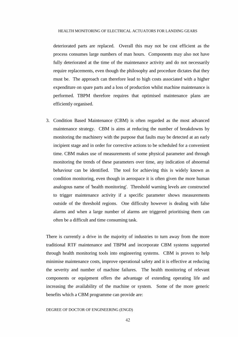
HEALTH MONITORING OF ELECTRICAL ACTUATORS FOR LANDING GEARS
DEGREE OF DOCTOR OF ENGINEERING (ENGD)
42
deteriorated parts are replaced. Overall this may not be cost efficient as the
process consumes large numbers of man hours. Components may also not have
fully deteriorated at the time of the maintenance activity and do not necessarily
require replacements, even though the philosophy and procedure dictates that they
must be. The approach can therefore lead to high costs associated with a higher
expenditure on spare parts and a loss of production whilst machine maintenance is
performed. TBPM therefore requires that optimised maintenance plans are
efficiently organised.
3. Condition Based Maintenance (CBM) is often regarded as the most advanced
maintenance strategy. CBM is aims at reducing the number of breakdowns by
monitoring the machinery with the purpose that faults may be detected at an early
incipient stage and in order for corrective actions to be scheduled for a convenient
time. CBM makes use of measurements of some physical parameter and through
monitoring the trends of these parameters over time, any indication of abnormal
behaviour can be identified. The tool for achieving this is widely known as
condition monitoring, even though in aerospace it is often given the more human
analogous name of 'health monitoring'. Threshold warning levels are constructed
to trigger maintenance activity if a specific parameter shows measurements
outside of the threshold regions. One difficulty however is dealing with false
alarms and when a large number of alarms are triggered prioritising them can
often be a difficult and time consuming task.
There is currently a drive in the majority of industries to turn away from the more
traditional RTF maintenance and TBPM and incorporate CBM systems supported
through health monitoring tools into engineering systems. CBM is proven to help
minimise maintenance costs, improve operational safety and it is effective at reducing
the severity and number of machine failures. The health monitoring of relevant
components or equipment offers the advantage of extending operating life and
increasing the availability of the machine or system. Some of the more generic
benefits which a CBM programme can provide are:

HEALTH MONITORING OF ELECTRICAL ACTUATORS FOR LANDING GEARS
DEGREE OF DOCTOR OF ENGINEERING (ENGD)
43
1. Change of maintenance philosophy
On condition
Opportunistic
Not “on failure” nor “per schedule”
Less interruption of mission schedule
2. Reduction in test equipment
Less intermediate and flight-line test equipment
35 percent less peculiar support equipment during system design and
development
Eliminated O-level test equipment
3. Benefits to the maintainer
Unprecedented insight into vehicle/fleet health
Less time spent on inspections
Better ability to plan maintenance
Simplified training
Improved fault detection
A CBM programme can be aimed at either fault diagnostics or prognostics (Jardine et
al. 2006). Diagnostics refers to a posterior event analysis and deals with fault
detection (indicates a fault has occurred), fault isolation (faulty component is
identified) and fault identification (the nature of the fault is determined). Prognosis is
a prior event analysis and deals with fault prediction before failure occurs.
It should be noted that a CBM programme is only worthwhile if the benefits can
significantly outweigh the costs of its introduction and upkeep. There are four generic
steps to CBM. These are the acquiring of data, the processing of the gathered data
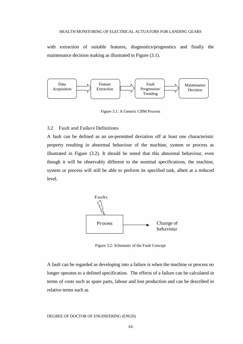
HEALTH MONITORING OF ELECTRICAL ACTUATORS FOR LANDING GEARS
DEGREE OF DOCTOR OF ENGINEERING (ENGD)
44
with extraction of suitable features, diagnostics/prognostics and finally the
maintenance decision making as illustrated in Figure (3.1).
Figure 3.1: A Generic CBM Process
3.2 Fault and Failure Definitions
A fault can be defined as an un-permitted deviation off at least one characteristic
property resulting in abnormal behaviour of the machine, system or process as
illustrated in Figure (3.2). It should be noted that this abnormal behaviour, even
though it will be observably different to the nominal specifications, the machine,
system or process will still be able to perform its specified task, albeit at a reduced
level.
Figure 3.2: Schematic of the Fault Concept
A fault can be regarded as developing into a failure is when the machine or process no
longer operates to a defined specification. The effects of a failure can be calculated in
terms of costs such as spare parts, labour and lost production and can be described in
relative terms such as
FeatureExtraction
FaultProgression/
Trending
MaintenanceDecision
DataAcquisition
Process Change ofbehaviour
Faults
HEALTH MONITORING OF ELECTRICAL ACTUATORS FOR LANDING GEARS
DEGREE OF DOCTOR OF ENGINEERING (ENGD)
45
High (expensive)
Medium (moderate)
Low (cheap)
The effects of failure can further be subdivided into four main categories
1. Safety/environmental failures may have associated risks of injury to people or to
the damage environment. There are often high risks in the petrochemical industry,
transport industry and within heavy manufacturing industries.
2. Lost production can have a serious consequence for a manufacturing process, such
as a car assembly line or the inability to fly an aircraft. Stopped operations can be
difficult and expensive to recover.
3. Secondary damage often results when a supporting piece of equipment such as an
oil lubrication pump fails causing further damage to other system components.
4. Replacement/scrap costs may be significant high if equipment performs poorly
and or if it fails. Specialist equipment can be very expensive to replace or repair.
Failure mechanisms can be described in two ways. The first is that the failure is only
dependant on the condition variables reflected by a predetermined fault level. This
gives a failure definition as ‘a failure occurs when the fault reaches a predetermined
level’. The second builds a model for the failure mechanism using historical data. A
definition of a failure can thus be ‘the event that the machine is operating at an
unsatisfactory level’ or it can be described as a functional failure where ‘the machine
cannot perform its intended function’ (Jardine et al 2006). Faults within a system are
dependent upon time. There dependencies may take the form of abrupt faults,
incipient faults or intermittent faults as illustrated in Figure (3.3).

HEALTH MONITORING OF ELECTRICAL ACTUATORS FOR LANDING GEARS
DEGREE OF DOCTOR OF ENGINEERING (ENGD)
46
Figure 3.3: a) abrupt fault, b) incipient fault, c)
intermittent
3.3 Diagnostics and Prognostic Definitions
Diagnostic capabilities traditionally relate to the area between a fault developing and
complete system catastrophic failure. Advances in diagnostic technologies have
recently enabled detections to be made at much earlier incipient fault stages. In order
to maximise the benefits of continued operational life, maintenance will often be
delayed until the early incipient fault progresses to a more severe state, but still
maintained before catastrophic failure occurs. This idea pushes out of the realms of
fault diagnostics and further towards the concept of employing a prognostic strategy.
If an incipient fault has been detected by the machine operator, and the decision has
been made to continue to run the machine. Then the operator will want to know how
long they can actually run the machine for before a failure event occurs. This is
known as the Remaining Useful Life (RUL) (Engel et. al 2000; Kothamasu et al.
2006). Figure (3.4) represents a failure progression timeline (Vachtsevanos et al.
2006).
f f f
t t t
ab
c

HEALTH MONITORING OF ELECTRICAL ACTUATORS FOR LANDING GEARS
DEGREE OF DOCTOR OF ENGINEERING (ENGD)
47
Figure 3.4: Failure Progression Time Line
(Vachtsevanos 2006)
If a new fully functioning machine begins to show signs of an incipient fault which
will further develop into an eventual catastrophic failure as the machine is continued
to be used. The RUL is the point along this particular failure progression timeline in
which to stop usage and carry out maintenance. The aim of estimating the RUL is to
maximise usage, optimise maintenance operations, minimise downtime and reduce
costs of spare parts and revenue losses. This is the real domain of prognostics and
requires a large array of tools and knowledge. There must be sufficient data or
knowledge on both the fault propagation process and on the failure mechanisms but
understanding this suffers from at the following difficulties.
State Awareness Detection
Determine effects onthe rest of aircraft
DIAGNOSTICS
Predicted remaining useful life
Secondary damage,catastrophic failure
Need: better modelsto determine failure
effects acrosssubsystems
Develop: useful liferemaining prediction
models
Desire: Advancedsensors and detectiontechniques to “see”
incipient faults
Need: understandingof fault to failureprogression rate
System, Subsystemor component
failure
Very early incipientfault
New workingorder
PROGNOSTICS
The goal is to detect “state changes” as far to the left as possible

HEALTH MONITORING OF ELECTRICAL ACTUATORS FOR LANDING GEARS
DEGREE OF DOCTOR OF ENGINEERING (ENGD)
48
The idea of trending has become a widely accepted approach to interpreting long term
behaviour thought the use of analyzing past behaviour. However there is also an
underlying assumption that the path from the initial fault and catastrophic failure is
predictable and smoothly changing. This is unfortunately rarely true and a range of
typical behaviours is shown in Figure (3.5).
Figure 3.5: Failure Progression Trends from Incipient
Fault to Catastrophic Failure (Starr 2005)
The choice of monitoring architecture and methodologies will heavily depend upon
the given application coupled with reliability requirements, safety issues, restrictions
Remaining Useful Life
Initial fault
Catastrophicfailure
HealthStatus
Time
B
AC
D
A The ideal transition between detection and failureB Trend from a high sensitivity sensor – stays highC The trend is a cumulative count with stepsD Trend from a low sensitivity sensor - late
HEALTH MONITORING OF ELECTRICAL ACTUATORS FOR LANDING GEARS
DEGREE OF DOCTOR OF ENGINEERING (ENGD)
49
on additional equipment and sensor limitations. Some monitoring techniques react too
slowly to an initial event, this is due to limitations of the sensor sensitivity, the sensor
may be physically remote from the fault or because the processing and analysis of the
signal is insensitive (Starr 2005). Factors such as this need to be considered in the
initial design stages of any health monitoring system an effective integrated systems
based strategy should therefore be adopted (Kacprzynski et al. 2002).
3.4 Review of Condition Based Maintenance System Requirements
Every individual CBM systems will have to meet specific performance measures for a
given characteristic. However a set of general requirements applicable to all CBM
systems will need to be met. A list of such requirements may include (Vachtsevanos
et al. 2006):
The CBM system must ensure enhanced maintainability and reduced
Operational and Support (O&S) costs over the lifetime of the monitored
systems.
The CBM system must be designed as an open-system architecture that
maximises ease of subsystem and component changes and replacements with
minimising system/process change.
The weight and complexity of the CBM system must be closely controlled
The CBM system must meet reliability, availability, maintainability and
durability requirements.
Structural and environmental requirements
Cost requirements
HEALTH MONITORING OF ELECTRICAL ACTUATORS FOR LANDING GEARS
DEGREE OF DOCTOR OF ENGINEERING (ENGD)
50
Power requirements
Compatibility with existing hardware.
The implementation of a CBM system can be expensive. If this initial investment is to
be made then there must be guaranteed significant O&S costs. If these savings do not
materialise then the use of the CBM system is not cost effective and consequently not
worthwhile. Most large scale engineering systems, such as aircraft continuously have
individual subsystems and components upgraded as new technology advances are
made. This ensures that the lifetime of the aircraft, efficiency and safety is
maximised. The CBM system must be able to adapt to these often small changes.
The total redesign of an actuator CBM system in order to allow it to work on an
upgraded actuator with different specifications would not be acceptable in terms costs,
in particular time and financial funding. The implementation of CBM should have no
adverse affects on the performance of the system in which it is attributed to. This
means that if diagnostic information matching the CBM performance requirements
cannot be gained without adversely affecting the systems performance or the CBM
equipment reliably operating in a given environment then CBM will not be suitable.
It should be noted that even though CBM practitioners would like to see their systems
on all engineering systems, it is certainly not applicable for all engineering systems.
One of the main concerns of CBM systems is their performance. In some cases a false
alarm will have huge financial and safety implications. If for example a CBM system
on an aircraft engine did not correctly raise an alarm, there are two implications. The
first is that passenger safety is affected; the second is that the aircraft may end up
being grounded in an undesirable location, where maintenance expertise or spare parts
are not easily available. Conversely if the alarm is triggered unnecessarily then the
aircraft would be grounded whilst inspection work is carried out leading to flight
delays, disgruntled passengers and lost revenue.
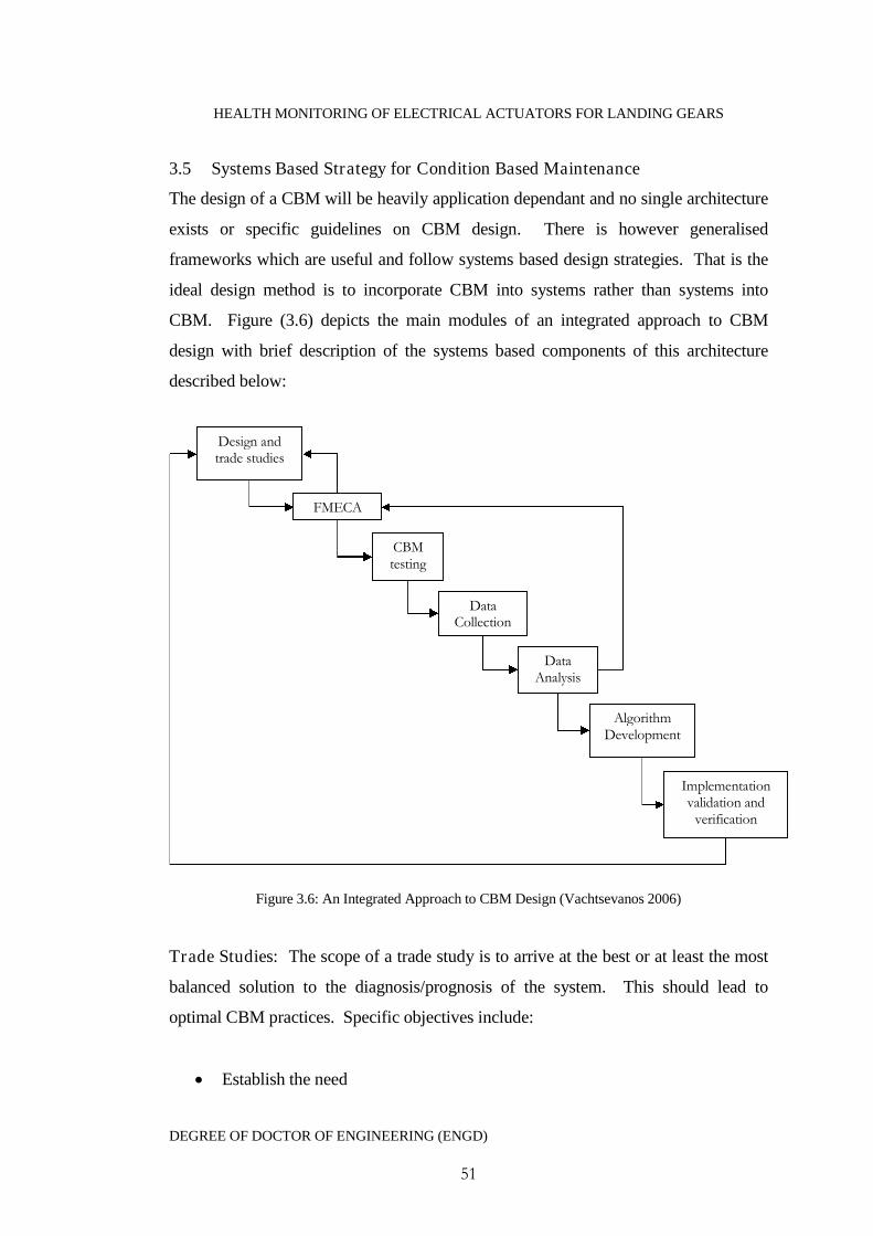
HEALTH MONITORING OF ELECTRICAL ACTUATORS FOR LANDING GEARS
DEGREE OF DOCTOR OF ENGINEERING (ENGD)
51
3.5 Systems Based Strategy for Condition Based Maintenance
The design of a CBM will be heavily application dependant and no single architecture
exists or specific guidelines on CBM design. There is however generalised
frameworks which are useful and follow systems based design strategies. That is the
ideal design method is to incorporate CBM into systems rather than systems into
CBM. Figure (3.6) depicts the main modules of an integrated approach to CBM
design with brief description of the systems based components of this architecture
described below:
Figure 3.6: An Integrated Approach to CBM Design (Vachtsevanos 2006)
Trade Studies: The scope of a trade study is to arrive at the best or at least the most
balanced solution to the diagnosis/prognosis of the system. This should lead to
optimal CBM practices. Specific objectives include:
Establish the need
Design andtrade studies
FMECA
CBMtesting
DataCollection
DataAnalysis
AlgorithmDevelopment
Implementationvalidation and
verification
HEALTH MONITORING OF ELECTRICAL ACTUATORS FOR LANDING GEARS
DEGREE OF DOCTOR OF ENGINEERING (ENGD)
52
Define the problem
Establish value objectives
Generate feasible alternatives
Make decisions
Failure Modes and Effects Analysis (FMEA): The cornerstone of a good CBM
system design is the understanding the physics of failure mechanisms. The use of a
FMEA is aimed at providing the designer with the tools and procedures that will lead
towards a systematic and thorough framework for design. A FMEA has the following
properties:
Identifying failure modes, their location, severity, frequency of occurrence and
testability
Relates failure events to their root causes
Explain the impact of faults/failures on the system, subsystem or component
performance
Make suggestions for the sensors/monitoring equipment required to detect and
track a particular fault
System CBM Test Plan: The objective of a CBM test plan is to operate the system
under controlled conditions on a laboratory testing rig or within a simulation
environment if an appropriate model describing the process exists. The testing can
also be performed under real operating regimes if possible to obtain baseline fault
data. Baseline fault data can be used to eventually train and validate
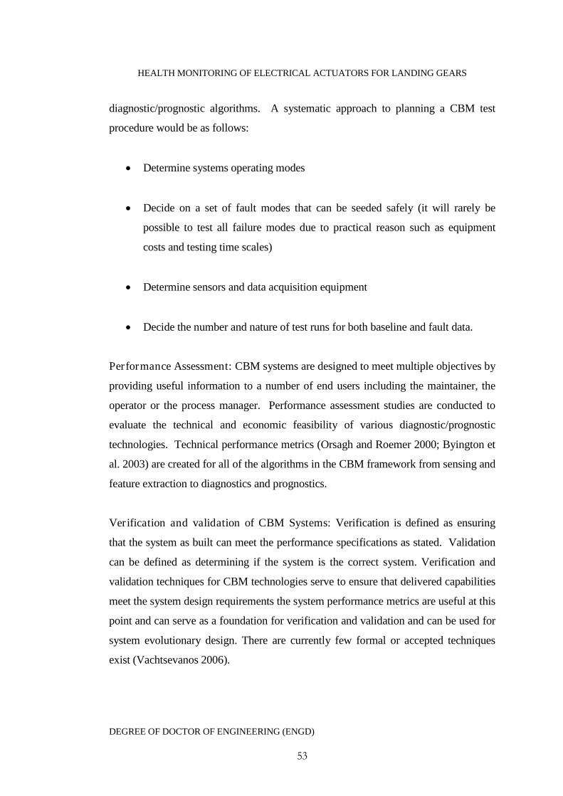
HEALTH MONITORING OF ELECTRICAL ACTUATORS FOR LANDING GEARS
DEGREE OF DOCTOR OF ENGINEERING (ENGD)
53
diagnostic/prognostic algorithms. A systematic approach to planning a CBM test
procedure would be as follows:
Determine systems operating modes
Decide on a set of fault modes that can be seeded safely (it will rarely be
possible to test all failure modes due to practical reason such as equipment
costs and testing time scales)
Determine sensors and data acquisition equipment
Decide the number and nature of test runs for both baseline and fault data.
Performance Assessment: CBM systems are designed to meet multiple objectives by
providing useful information to a number of end users including the maintainer, the
operator or the process manager. Performance assessment studies are conducted to
evaluate the technical and economic feasibility of various diagnostic/prognostic
technologies. Technical performance metrics (Orsagh and Roemer 2000; Byington et
al. 2003) are created for all of the algorithms in the CBM framework from sensing and
feature extraction to diagnostics and prognostics.
Verification and validation of CBM Systems: Verification is defined as ensuring
that the system as built can meet the performance specifications as stated. Validation
can be defined as determining if the system is the correct system. Verification and
validation techniques for CBM technologies serve to ensure that delivered capabilities
meet the system design requirements the system performance metrics are useful at this
point and can serve as a foundation for verification and validation and can be used for
system evolutionary design. There are currently few formal or accepted techniques
exist (Vachtsevanos 2006).
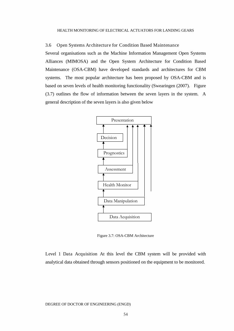
HEALTH MONITORING OF ELECTRICAL ACTUATORS FOR LANDING GEARS
DEGREE OF DOCTOR OF ENGINEERING (ENGD)
54
3.6 Open Systems Architecture for Condition Based Maintenance
Several organisations such as the Machine Information Management Open Systems
Alliances (MIMOSA) and the Open System Architecture for Condition Based
Maintenance (OSA-CBM) have developed standards and architectures for CBM
systems. The most popular architecture has been proposed by OSA-CBM and is
based on seven levels of health monitoring functionality (Swearingen (2007). Figure
(3.7) outlines the flow of information between the seven layers in the system. A
general description of the seven layers is also given below
Figure 3.7: OSA-CBM Architecture
Level 1 Data Acquisition At this level the CBM system will be provided with
analytical data obtained through sensors positioned on the equipment to be monitored.
Data Acquisition
Data Manipulation
Health Monitor
Assessment
Prognostics
Presentation
Prognostics
Decision

HEALTH MONITORING OF ELECTRICAL ACTUATORS FOR LANDING GEARS
DEGREE OF DOCTOR OF ENGINEERING (ENGD)
55
Level 2 Data Manipulation Data obtained from level 1 will be received and
processed at this level and will output digitally filtered data and for example frequency
spectra or other extracted CBM features.
Level 3 Health Monitor The health monitoring level will be focused on comparing
the processed data against what would be expected in a healthy system. The
capability of generating CBM alarms through pre-set threshold levels will also be
available at this level.
Level 4 Health Assessment At this level the health assessment will be able to
determine if the monitored components health has degraded. The health assessment
will utilise and align fault symptoms generated at the health monitoring level to
propose fault possibilities and give a measure of fault severity.
Level 5 Prognostics Data and information available from all other levels is available
together with failure models and prognostic algorithms to calculate the future health of
the system. The prognostics level will return the health status for a specific time and
as a measure of the remaining useful life.
Level 6 Decision The focus here will be to generate a set of recommended actions.
Maintenance requirements, legislations, costs and risks will be taken into
consideration in order for decisions on effective landing gear maintenance scheduling
to be made.
Level 7 Presentation The presentation level will provide a transparent view of the
information obtained from the previous levels. The most important of which will be
the health assessment, prognostics and the decision levels. The ability to see the other
levels will be a crucial factor if any justifications are required.
HEALTH MONITORING OF ELECTRICAL ACTUATORS FOR LANDING GEARS
DEGREE OF DOCTOR OF ENGINEERING (ENGD)
56
3.7 Sensor Systems
The use of sensor equipment is fundamental to successful CBM. A sensor can be
defined as an electrical or mechanical device which maps the value of some
environmental attribute to a quantifiable measurement. The use of sensor suites
employed to collect data is what leads to an online realisation of diagnostic and
prognostic algorithms. Strategic issues which must be addressed include the type and
number of sensors to be used, location, cost, weight and dynamic range. Optimising
the best suite of sensors and in what location and capacity to use them is no trivial
task. There are however guidelines available for choosing sensor locations in military
and aerospace systems (Padula and Kincaid 1999). Traditionally sensors will already
have been placed as part of a control system or for the purpose of monitoring
performance objectives.
Every sensor detects some aspect of its environment in which it is operating. There are
numerous types of conventional sensors available and sensor technology progresses
rapidly in terms of specialisation, miniaturisation and performance characteristics
(Kanoun and Trankler 2004). It is not in the scope of this thesis to give a full detailed
review on the operating principles of individual sensor type but a brief non exhaustive
list is given below.
Mechanical Sensors Pressure sensors, accelerometers, displacement
transducers, strain gauges, force sensors, ultrasonic sensors, angular velocity
sensors and acoustic wave sensors.
Thermal Sensors Thermocouples, diode and transistor temperature sensors,
thermistors, pyroelectric and piezoelectric thermometers.
Optical Sensors Photoconductors, photodiodes, phototransistors, position-
sensitive photodetectors.
HEALTH MONITORING OF ELECTRICAL ACTUATORS FOR LANDING GEARS
DEGREE OF DOCTOR OF ENGINEERING (ENGD)
57
Magnetic Sensors Megneto resistors, hall-effect devices and magnetometers
Other Sensors Viscosity sensors, proximity sensors, altimeters, gas sensors,
humidity sensors and acoustic velocity sensors
3.7.1 Technology Aspects of Sensors
There are a variety of aspects to consider when choosing appropriate sensors; some of
the more important are reviewed below (Fraden 1993):
Sensitivity: the minimum magnitude of the input signal required to produce a
specified output signal.
Measuring range: the range of values that the sensor can measure effectively.
Resolution: the smallest change the sensor can detect in the parameter that is
being measured.
Stability: changes within the sensors performance over a period of minutes,
hours or days is known as the short-term stability. Long-term stability
depends upon the operating conditions of the sensor and is related to the aging
of the sensors electrical, mechanical or thermal material properties. Long-term
stability is an important aspect to consider for sensors required to perform
precision measurements.
Reliability: the ability of a sensor to perform a required function under the
given operating conditions for a given period of time.
Accuracy: this is measured as the highest deviation of a value represented by
the sensor from an ideal or true value at its input.
Selectivity: the ability of the sensor to reject other nearby signals
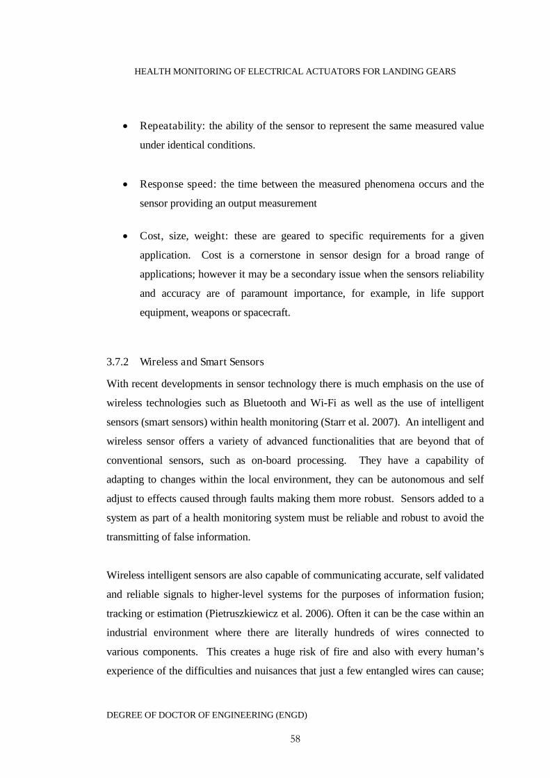
HEALTH MONITORING OF ELECTRICAL ACTUATORS FOR LANDING GEARS
DEGREE OF DOCTOR OF ENGINEERING (ENGD)
58
Repeatability: the ability of the sensor to represent the same measured value
under identical conditions.
Response speed: the time between the measured phenomena occurs and the
sensor providing an output measurement
Cost, size, weight: these are geared to specific requirements for a given
application. Cost is a cornerstone in sensor design for a broad range of
applications; however it may be a secondary issue when the sensors reliability
and accuracy are of paramount importance, for example, in life support
equipment, weapons or spacecraft.
3.7.2 Wireless and Smart Sensors
With recent developments in sensor technology there is much emphasis on the use of
wireless technologies such as Bluetooth and Wi-Fi as well as the use of intelligent
sensors (smart sensors) within health monitoring (Starr et al. 2007). An intelligent and
wireless sensor offers a variety of advanced functionalities that are beyond that of
conventional sensors, such as on-board processing. They have a capability of
adapting to changes within the local environment, they can be autonomous and self
adjust to effects caused through faults making them more robust. Sensors added to a
system as part of a health monitoring system must be reliable and robust to avoid the
transmitting of false information.
Wireless intelligent sensors are also capable of communicating accurate, self validated
and reliable signals to higher-level systems for the purposes of information fusion;
tracking or estimation (Pietruszkiewicz et al. 2006). Often it can be the case within an
industrial environment where there are literally hundreds of wires connected to
various components. This creates a huge risk of fire and also with every human’s
experience of the difficulties and nuisances that just a few entangled wires can cause;

HEALTH MONITORING OF ELECTRICAL ACTUATORS FOR LANDING GEARS
DEGREE OF DOCTOR OF ENGINEERING (ENGD)
59
industry takes very serious the possibility use of wireless smart sensing. Smart
wireless sensors in a maintenance role provide the ability to remotely monitor
machinery from potentially any global position outside of the machines location. This
has recently been investigated through a sizeable European Union 6th Framework
Programme known as Dynamite (Dynamic Decisions in Maintenance)*.
Remote health monitoring is particularly suitable to the monitoring of aerospace
systems by the very nature of the systems. Aircraft are rarely in one geographical
location for very long and each airport must have suitably trained personnel to inspect
key aircraft systems. With remote health monitoring data can be transmitted to any
location reducing the number of maintenance personnel stationed at each airport.
3.7.3 Multiple Sensor Networks
Experience in industry has shown that there are significant advantages offered by
utilising multiple sensors in an application in the form of sensor networks. These
advantages can include:
Robust system: If a health monitoring system depends upon a single sensor
source then decisions may not be robust and reliable. If the single data source
fails, then the output of the monitoring system will be adversely affected.
Fusion of several sources of data can have a higher fault-tolerance rate.
Situation awareness: This can increase reaction time by taking advantage of
different sensor sources. By fusing the results would give a better situation
awareness which would lead to better decision making.
Improved data accuracy: Fusing of multiple data sources can remove data
ambiguity improving data accuracy and reducing uncertainty.
* The DYNAMITE project ran between 2005and 2008, consisted of a budget of 6.3 million Euros and 17 partners. Ofwhich the University of Manchester was a major academic partner.
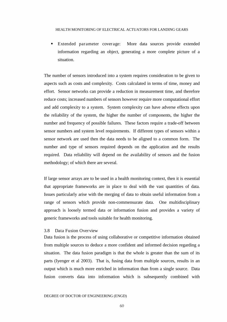
HEALTH MONITORING OF ELECTRICAL ACTUATORS FOR LANDING GEARS
DEGREE OF DOCTOR OF ENGINEERING (ENGD)
60
Extended parameter coverage: More data sources provide extended
information regarding an object, generating a more complete picture of a
situation.
The number of sensors introduced into a system requires consideration to be given to
aspects such as costs and complexity. Costs calculated in terms of time, money and
effort. Sensor networks can provide a reduction in measurement time, and therefore
reduce costs; increased numbers of sensors however require more computational effort
and add complexity to a system. System complexity can have adverse effects upon
the reliability of the system, the higher the number of components, the higher the
number and frequency of possible failures. These factors require a trade-off between
sensor numbers and system level requirements. If different types of sensors within a
sensor network are used then the data needs to be aligned to a common form. The
number and type of sensors required depends on the application and the results
required. Data reliability will depend on the availability of sensors and the fusion
methodology; of which there are several.
If large sensor arrays are to be used in a health monitoring context, then it is essential
that appropriate frameworks are in place to deal with the vast quantities of data.
Issues particularly arise with the merging of data to obtain useful information from a
range of sensors which provide non-commensurate data. One multidisciplinary
approach is loosely termed data or information fusion and provides a variety of
generic frameworks and tools suitable for health monitoring.
3.8 Data Fusion Overview
Data fusion is the process of using collaborative or competitive information obtained
from multiple sources to deduce a more confident and informed decision regarding a
situation. The data fusion paradigm is that the whole is greater than the sum of its
parts (Iyenger et al 2003). That is, fusing data from multiple sources, results in an
output which is much more enriched in information than from a single source. Data
fusion converts data into information which is subsequently combined with
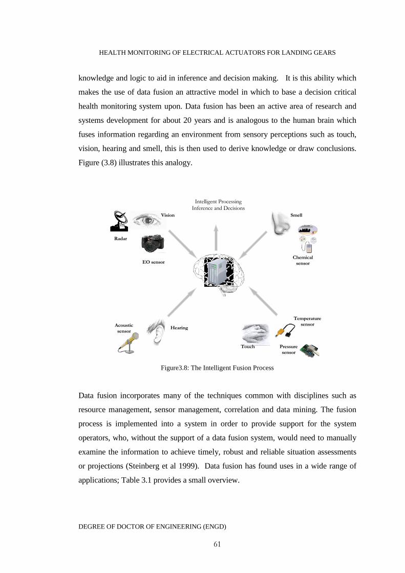
HEALTH MONITORING OF ELECTRICAL ACTUATORS FOR LANDING GEARS
DEGREE OF DOCTOR OF ENGINEERING (ENGD)
61
knowledge and logic to aid in inference and decision making. It is this ability which
makes the use of data fusion an attractive model in which to base a decision critical
health monitoring system upon. Data fusion has been an active area of research and
systems development for about 20 years and is analogous to the human brain which
fuses information regarding an environment from sensory perceptions such as touch,
vision, hearing and smell, this is then used to derive knowledge or draw conclusions.
Figure (3.8) illustrates this analogy.
Figure3.8: The Intelligent Fusion Process
Data fusion incorporates many of the techniques common with disciplines such as
resource management, sensor management, correlation and data mining. The fusion
process is implemented into a system in order to provide support for the system
operators, who, without the support of a data fusion system, would need to manually
examine the information to achieve timely, robust and reliable situation assessments
or projections (Steinberg et al 1999). Data fusion has found uses in a wide range of
applications; Table 3.1 provides a small overview.
Acousticsensor
Hearing
Temperaturesensor
Pressuresensor
EO sensor
Radar
Vision
Touch
Chemicalsensor
Intelligent ProcessingInference and Decisions
Smell

HEALTH MONITORING OF ELECTRICAL ACTUATORS FOR LANDING GEARS
DEGREE OF DOCTOR OF ENGINEERING (ENGD)
62
Table 3.1: Overview of Data Fusion ApplicationsApplication Inference Primary Data
Medical Diagnostics(Pattichis et al. 2001)
The identificationand location ofabnormalities anddisease
X-rays Temperature NMR Chemical/biological
data Visual inspections
Robot Navigation (Luo et al1988)
The identificationand location ofobstacles and objects.
Acoustic signals EM signals Infrared signals
Condition BasedMaintenance (Starr et al.2002a, 2002b)
Detection, diagnosisand isolation ofmachine faults andcorrectivemaintenancerecommendations
Acoustic signals Vibrations Temperature Wear debris Current signatures
Transport Systems (ElFauzi 2004)
Fusion ofinformation toprovide better travelrelated information
CCTV Weather reports Incident reports Vehicle location
3.8.1 Fusion Processes
Before discussing fusion strategies it should be noted that the fusing of multiple data
streams is by no means a trivial process, the decision to implement data fusion into a
system has its associated difficulties, some of which are outlined below:
Sensor diversity: sensors will be of differing types, all have different
properties including outputs, synchronisation, and location.
Data diversity: different sensors make different measurements and it is highly
likely that they will have different characteristics and dimensionality (e.g.
miles feet and inches).
Sensor calibration: sensors will need to be correctly calibrated to cope with
errors and uncertainties.
HEALTH MONITORING OF ELECTRICAL ACTUATORS FOR LANDING GEARS
DEGREE OF DOCTOR OF ENGINEERING (ENGD)
63
Sensor limitations: sensors all have limitations on the environments that they
can operate in and measurement ranges etc
This is a non-exclusive list of difficulties that arise during data fusion implementation.
A prime architectural issue is what level fusion is to take place. Fusion can take place
on three levels, depending on the application requirements; these are fusing at the
data, feature and decision levels.
Data level fusion where information obtained from sensor-arrays are fused
together in order to validate signals and create features.
Feature level fusion combines features are extracted from the raw sensor data
and are then combined to obtain diagnostic information.
Decision level fusion incorporates experience-based information such as
physical model predictions, failure rates, management data and heuristic
knowledge to provide confident decisions.
3.8.2 Data Fusion Models
In a centralised fusion all of the available data is collected together into a central
processor where it is fused together, allowing decisions to be made. The fusion
process is performed on raw data and is usually commensurate, for example, infrared
images and satellite images and fused using pattern recognition, estimation and
statistical techniques which require high computational requirements. A centralised
fusion model is shown in Figure (3.9).
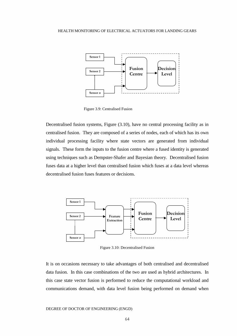
HEALTH MONITORING OF ELECTRICAL ACTUATORS FOR LANDING GEARS
DEGREE OF DOCTOR OF ENGINEERING (ENGD)
64
Figure 3.9: Centralised Fusion
Decentralised fusion systems, Figure (3.10), have no central processing facility as in
centralised fusion. They are composed of a series of nodes, each of which has its own
individual processing facility where state vectors are generated from individual
signals. These form the inputs to the fusion centre where a fused identity is generated
using techniques such as Dempster-Shafer and Bayesian theory. Decentralised fusion
fuses data at a higher level than centralised fusion which fuses at a data level whereas
decentralised fusion fuses features or decisions.
Figure 3.10: Decentralised Fusion
It is on occasions necessary to take advantages of both centralised and decentralised
data fusion. In this case combinations of the two are used as hybrid architectures. In
this case state vector fusion is performed to reduce the computational workload and
communications demand, with data level fusion being performed on demand when
Sensor 2
Sensor 1
Sensor n
FusionCentre
DecisionLevel
FeatureExtraction
FusionCentre
DecisionLevel
Sensor 2
Sensor 1
Sensor n

HEALTH MONITORING OF ELECTRICAL ACTUATORS FOR LANDING GEARS
DEGREE OF DOCTOR OF ENGINEERING (ENGD)
65
more accuracy is required. Alternatively a combination of state vectors and raw data
may be fused depending upon available sensors.
3.8.3 Architecture Selection
The centralised fusion architecture is generally more often used than the decentralised
or hybrid options. The use of centralised architectures may be computationally
intensive but they carry the advantage of developing a picture of an object from the
raw data. Original raw data contains information regarding data quality, which may be
lost or diminished in higher fusion levels used in decentralised fusion (Linas and Hall
1998). Decentralised architectures reduce the amount of data and hence require much
less computational effort and data handling capabilities, but at the cost of adding a
signal processing unit to each sensor increases the overall system complexity. The
hybrid architecture is the most complex architecture to use but it does offer the most
flexible fusion approach, a hybrid fusion system requires a monitoring system/person
to select between data and state vector fusion.
There is no individually best architecture to adopt when designing a data fusion
system, the choice of fusion architecture is a matter of the requirements of the
application and is therefore a system-engineering problem. These include data
exploitation level, data availability, strategic planning, computing constraints, cost
along with temporal and special issues.
3.8.4 The JDL Data Fusion Process Model
Many generic data process models exist, several in depth reviews of the various
models have been provided in the literature (Esteban eta al 2005). However the most
intuitive and applicable model to consider for the current application is that proposed
by the Joint Directors of Laboratories (JDL) data fusion sub-panel within the US
Department of Defence to aid in the development of military systems.
The JDL model is a generalised framework which has found popular use in many data
fusion applications including the development of intelligent health monitoring. The
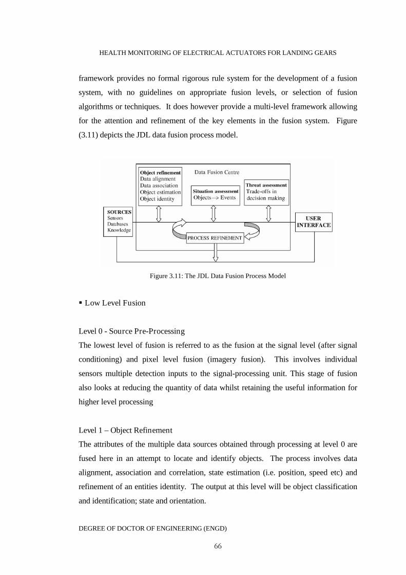
HEALTH MONITORING OF ELECTRICAL ACTUATORS FOR LANDING GEARS
DEGREE OF DOCTOR OF ENGINEERING (ENGD)
66
framework provides no formal rigorous rule system for the development of a fusion
system, with no guidelines on appropriate fusion levels, or selection of fusion
algorithms or techniques. It does however provide a multi-level framework allowing
for the attention and refinement of the key elements in the fusion system. Figure
(3.11) depicts the JDL data fusion process model.
Figure 3.11: The JDL Data Fusion Process Model
Low Level Fusion
Level 0 - Source Pre-Processing
The lowest level of fusion is referred to as the fusion at the signal level (after signal
conditioning) and pixel level fusion (imagery fusion). This involves individual
sensors multiple detection inputs to the signal-processing unit. This stage of fusion
also looks at reducing the quantity of data whilst retaining the useful information for
higher level processing
Level 1 – Object Refinement
The attributes of the multiple data sources obtained through processing at level 0 are
fused here in an attempt to locate and identify objects. The process involves data
alignment, association and correlation, state estimation (i.e. position, speed etc) and
refinement of an entities identity. The output at this level will be object classification
and identification; state and orientation.

HEALTH MONITORING OF ELECTRICAL ACTUATORS FOR LANDING GEARS
DEGREE OF DOCTOR OF ENGINEERING (ENGD)
67
Higher Level Fusion
Level 2 – Situation Assessment
Level 2 processing aims to provide a higher level of understanding of the output from
level 1 processing. It identifies the most probable situation based on the observed data
and events through establishing relationships among objects and assessing these
relationships to identify the meaning of entities in a specific environment. The output
at this level would for example be a collection of higher-order inferences providing a
view of what is happening.
Level 3 – Impact Assessment
The purpose of processing at this level is to assess what the impact of the events
derived from level 2 processing. This could include assessing the threat or danger
level, predicting the possible outcome, assessing asset vulnerability and analysing the
advantages and disadvantages of taking one course of action over another
Level 4 – Process Refinement
Level 4 processing is the refinement stage. This is often implemented with the
purpose of improving the fusion process between levels 0 to 3. This level can identify
potential sources of information enhancement, manage resources such as the sensors
and prioritise tasks.
Implementing all levels of fusion is a complicated task, low and higher level fusion
processes both have distinct operational functions; low level fusion must address the
complexity of association, short term history process and structural issues. High-level
fusion handles intelligently the integration of present information, long-term history
and the problems with recalling information
3.9 Health Monitoring Techniques
Once the decision to design a health monitoring system has been made, the next step
is to determine the choice of variables to be monitored. There are a multitude of
HEALTH MONITORING OF ELECTRICAL ACTUATORS FOR LANDING GEARS
DEGREE OF DOCTOR OF ENGINEERING (ENGD)
68
techniques available for measuring and associating variables with faults. Some of
these require specialist equipment, specialist training and some require complex signal
processing techniques each of these factors affect the monitoring choice. Each
technique is appropriate for different machine or system types and the detecting of
particular failures and this section reviews the main signal based approaches.
3.9.1 Vibration Monitoring
The health monitoring market has for 40 years been dominated by frequency analysis
of machine vibrations. All dynamical systems will generate vibrations whilst in
operation (Rao 1996). Individual machine components will usually have distinctive
vibration patterns which are symptomatic of their health. These vibration patterns if
monitored and analysed can provide a good indication of deterioration in machine
health. A machines vibration signature is a complex signal which is a mixture of
sinusoidal waveforms all of different amplitudes, frequencies and phase differences
which relate to fundamental rotational speed. Vibration can be measured in terms of
various parameters some of the most popular include displacement, velocity,
acceleration, frequency, bandwidth, spike energy or power spectral density.
The use of vibration signals in health monitoring depends upon the quality of the
measured signal. This means that the choice and location of measuring transducers is
of particular importance if the health monitoring system is to be based upon vibration
analysis. There are a variety of vibration signal processing techniques and methods
used to distinguish faults such as imbalance, looseness, misalignment, wear, poor
lubrication and structural cracks in rotating machinery (Wua 2009; Poyhonen et al.
2004), these include cepstrum analysis, spectrum analysis and autoregressive
modelling. Other methods include the measurement of spike energy and shock pulse
methods. These can be used when there is no deformation present and is successful at
detecting a lack of lubrication and wear in aerospace engine bearings (Byington et al.
2004). Vibration analysis has also found popular use in Structural health Monitoring
of composite materials (Montalvao et al. 2006) and in the health monitoring of
HEALTH MONITORING OF ELECTRICAL ACTUATORS FOR LANDING GEARS
DEGREE OF DOCTOR OF ENGINEERING (ENGD)
69
traditional aerospace structures (Bovio and Lecce 2006) but is applied extensively to
rotating machinery.
3.9.2 Lubricant Wear Debris
Lubrication in a system is usually required for reducing friction, cooling components
and to clean load bearing surfaces. In systems where it is difficult or impossible to
mount sensors it can be beneficial to monitor the actual lubricant which is in direct
contact with moving parts. This can be an effective way of not only assessing the oil
quality but also the condition of the components in which the fluids have come into
contact with. As time passes the lubricant will begin to degrade and components will
begin experience increased friction due to metal-metal contact leading to wear. The
result of which will be a build-up of both metallic and non metallic particles within the
system. Other effects which can lead to the presence of wear debris are the failure of
filters or the corrosion of the metallic components. By observing the size, quantity,
material composition and the shape of wear debris a number of identifiable faults may
be classified (Khan et al 2008).
The material composition can identify which particular component the particles have
originated from. Their shape can help to indicate the mechanism which is causing the
build up of debris and the quantity and size of the particles can give a good indication
of the rate at which any damage is occurring (Khan and Starr 2006). The monitoring
of the lubrication also offers the ability to remove any large particles through the use
of filters and magnets before they can cause more wear and damage to seals through
abrasive effects. When monitoring lubricant wear debris measurements should be
taken from the path of the lubrications flow to get accurate results. These
measurements are then analysed using techniques such as the use of magnetic chip
detectors, ferrography, spectrography or visual inspections (both manual and
automated).
HEALTH MONITORING OF ELECTRICAL ACTUATORS FOR LANDING GEARS
DEGREE OF DOCTOR OF ENGINEERING (ENGD)
70
3.9.3 Motor Current Signature Monitoring
Motor Current Signature Analysis (MCSA) is a technology developed for the specific
task of monitoring electrical machinery (Nandi et al. 2005). Many of the vibration
techniques outlined earlier can be used to effectively diagnose most faults within
electrical motors. It is argued that a better and fuller understanding of the motors
electrical and mechanical condition can be obtained by monitoring the current passing
through it. MCSA is based upon small time independent motor load variations
generated from within the mechanical system and converting them into electrical
signals that flow along the cable supplying the power to the motor. These signals can
be extracted and used as an indicator to the motors condition. Measured current
signatures can be analysed in both the time and the frequency domain, with analysis in
the time domain can be useful in the initial or final stages of the motors operation.
Monitoring motor current has a number of beneficial strengths and can provide a non-
intrusive monitoring capability. Through the use of Fourier analysis the current
signature can provide good degradation and diagnostic information on damage such as
broken rotors, unbalanced magnetic forces, winding problems, mechanical unbalance
and bent shafts amongst others. The monitoring of the electrical current has a high
level of sensitivity to a variety of mechanical disorders affecting the machines
operation and it is cost effective and can be performed by relatively unskilled
personnel. Literature surveys have shown that MCSA is a popular tool in the fault
diagnosis of electrical machines and has found extensive use in the monitoring of
induction drives used for driving of a vast range of high load bearing machinery
(Thomson and Fenger 2001; Bendouzid 2000). A current based detection of faults has
been shown as a viable and cheaper than vibration analysis tool for use with brushless
DC motors to detect faults in rotors (Rajagopalan 2004) and has been demonstrated by
successfully detecting broken gear teeth, a lack of lubrication and wear particles in the
gear lubrication (Rajagopalan 2006).
HEALTH MONITORING OF ELECTRICAL ACTUATORS FOR LANDING GEARS
DEGREE OF DOCTOR OF ENGINEERING (ENGD)
71
3.9.4 Thermal Monitoring
An early indication of component failure can be achieved through the monitoring of
temperature changes. This is a particularly applicable technique for components
which generate, transfer or store energy as heat. These include thermal insulation,
motors, coolant/lubricant, electrical wiring and bearing housings. A temperature rise
in these components will be indicative of a developing fault and may be caused by
such things as increased friction due to lack of lubricant, incorrect electrical loading
and damaged thermal or electrical insulation.
There are two categories of thermal monitoring methods: contact and non-contact.
Contact methods will require a temperature measuring device such as a visual
indicator (mercury thermometers, temperature paints), thermocouple or resistive
devices to be placed on or within the surface of the monitored component. The use of
non-contact methods have the advantage that large areas can be surveyed quickly and
at a distance and is particularly useful where access is difficult such as inside rotating
equipment. This approach uses the principle that all bodies radiate energy in
proportion to their temperature and that it is possible to relate the wavelength of the
radiation to the temperature of the radiating body.
3.9.5 Acoustic Emission Monitoring
Acoustic Emissions (AE) are produced from the rapid release of energy from sources
within a material. These waves are converted into voltage signals by the use of small
piezoelectric sensors mounted in suitable locations. The sensor response and front
end filters remove noise below 100 kHz, this includes most audible noise. This allows
acoustic emissions to be used to measure the condition of a structure even when
ambient noise levels are extremely high. Acoustic emission sources include fractures,
plastic deformation, impacts, and friction along with many other processes. Acoustic
emission is sensitive enough to detect cracks and fractures down to a few hundred
square micrometers or less (Finlayson et al. 2001).
HEALTH MONITORING OF ELECTRICAL ACTUATORS FOR LANDING GEARS
DEGREE OF DOCTOR OF ENGINEERING (ENGD)
72
3.9.6 Performance Monitoring
Performance monitoring makes use of process information to indicate the efficiency
of equipment. Any changes will be an indication that the condition is deteriorating.
The advantages of performance monitoring are that it is cheap and simple to
implement because most of the required instrumentation already exists. The main
disadvantage is that most of the parameters which can be measured will depend on
some other variable making it difficult to calculate a performance indicator.
3.9.7 Corrosion Monitoring
Any fluid present in a process or in the operating environment can lead to a corrosion
of parts. Severe corrosion can then lead to a gradual or sudden breakdown. A
deterioration in performance caused by corrosion may however be detected through
other monitoring techniques. Corrosion is usually a problem more associated with
structural components and techniques used to determine its extent include chemical
analysis, ultrasonic testing and electrical methods.
3.10 Critical Review of Monitoring Methods
Vibration analysis works well for continuously rotating machinery where vibrations
provide good stable symptoms of health. The electric actuation as part of the new ‘all
electric landing gear’ which is the subject of this thesis operates in a start and stop
fashion at often irregular intervals. The actuation mechanisms have varying speeds
throughout the operational cycle with varying friction, environment and mechanical
advantage. Vibration is dependent upon the rotating speed of the machine and if it
operates under varying speed, its vibrations will become non-stationary. The
rotational angle does not remain directly proportional with time and so conventional
methods of signal processing become inappropriate when monitoring the vibrations of
varying speed machinery.
There are various methods which can be used for motor current signature monitoring
(Kliman and Stein 1992) which has been shown to work well in fault detection
schemes. However they all assume that the load remains constant and does not vary
HEALTH MONITORING OF ELECTRICAL ACTUATORS FOR LANDING GEARS
DEGREE OF DOCTOR OF ENGINEERING (ENGD)
73
with rotational speed. Electromechanical actuation devices work by unlocking a
mechanism and causing the displacement of a lever-actuated or gear transmission,
linear displacement of an object, with it being stopped against a locking mechanism.
This leads to higher loads at the beginning and end of its operation. Variable friction
also creates non constant loads. If the load varies with rotor position such as it does in
a reciprocating compressor or in the proposed motor drives, then the current will
contain spectral components which will coincide and overlap with those caused by
any fault condition. This complicates any fault detection scheme. The problem of
motor current spectral analysis in the presence of time-varying loads in AC induction
machines is addressed by (Schoen and Habetler 1995). Other treatments such as
Wavelet Packet Decomposition with application to induction drives (Zhongming et al.
2003) has successfully differentiated between healthy and faulty conditions by giving
good feature representations of multiple frequency resolutions for faulty conditions. It
has been shown to give a better treatment of the stator current than the currently used
Fourier techniques in the detecting of bearing faults under varying speeds and loads
(Eren and Devaney 2002). There is however very little published work on the use of
MCSA for DC motors operating in a similar fashion to the proposed drives.
Vibration analysis has proven to be the most reliable and popular method of gear fault
diagnosis but the cost of sensors such as accelerometers and the associated wiring has
made the measuring of vibration a disadvantage in cost-sensitive areas. MCSA
however has shown to be a cost effective alternative to vibration analysis in the
detection of gear faults and has the potential to overtake vibration in detecting faulty
gears due to the advantage of it being cheap and easy to use.
In aircraft landing gear there are also problems associated with the use of health
monitoring based upon performance monitoring. Warm motor starts are as common
as cold motor starts due to varying operating environments which will lead to widely
varying current signatures meaning that conventional threshold warning levels will not
work. This is also the case with thermal monitoring of the motors, where the ambient
temperatures can affect the measurements. The temperatures in the landing gear bay
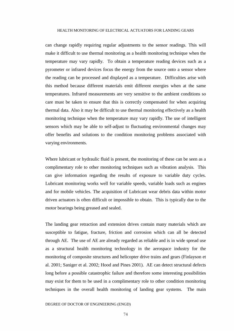
HEALTH MONITORING OF ELECTRICAL ACTUATORS FOR LANDING GEARS
DEGREE OF DOCTOR OF ENGINEERING (ENGD)
74
can change rapidly requiring regular adjustments to the sensor readings. This will
make it difficult to use thermal monitoring as a health monitoring technique when the
temperature may vary rapidly. To obtain a temperature reading devices such as a
pyrometer or infrared devices focus the energy from the source onto a sensor where
the reading can be processed and displayed as a temperature. Difficulties arise with
this method because different materials emit different energies when at the same
temperatures. Infrared measurements are very sensitive to the ambient conditions so
care must be taken to ensure that this is correctly compensated for when acquiring
thermal data. Also it may be difficult to use thermal monitoring effectively as a health
monitoring technique when the temperature may vary rapidly. The use of intelligent
sensors which may be able to self-adjust to fluctuating environmental changes may
offer benefits and solutions to the condition monitoring problems associated with
varying environments.
Where lubricant or hydraulic fluid is present, the monitoring of these can be seen as a
complimentary role to other monitoring techniques such as vibration analysis. This
can give information regarding the results of exposure to variable duty cycles.
Lubricant monitoring works well for variable speeds, variable loads such as engines
and for mobile vehicles. The acquisition of Lubricant wear debris data within motor
driven actuators is often difficult or impossible to obtain. This is typically due to the
motor bearings being greased and sealed.
The landing gear retraction and extension drives contain many materials which are
susceptible to fatigue, fracture, friction and corrosion which can all be detected
through AE. The use of AE are already regarded as reliable and is in wide spread use
as a structural health monitoring technology in the aerospace industry for the
monitoring of composite structures and helicopter drive trains and gears (Finlayson et
al. 2001; Saniger et al. 2002; Hood and Pines 2001). AE can detect structural defects
long before a possible catastrophic failure and therefore some interesting possibilities
may exist for them to be used in a complimentary role to other condition monitoring
techniques in the overall health monitoring of landing gear systems. The main
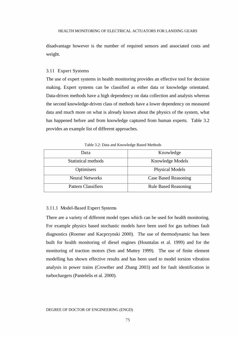
HEALTH MONITORING OF ELECTRICAL ACTUATORS FOR LANDING GEARS
DEGREE OF DOCTOR OF ENGINEERING (ENGD)
75
disadvantage however is the number of required sensors and associated costs and
weight.
3.11 Expert Systems
The use of expert systems in health monitoring provides an effective tool for decision
making. Expert systems can be classified as either data or knowledge orientated.
Data-driven methods have a high dependency on data collection and analysis whereas
the second knowledge-driven class of methods have a lower dependency on measured
data and much more on what is already known about the physics of the system, what
has happened before and from knowledge captured from human experts. Table 3.2
provides an example list of different approaches.
Table 3.2: Data and Knowledge Based Methods
Data Knowledge
Statistical methods Knowledge Models
Optimisers Physical Models
Neural Networks Case Based Reasoning
Pattern Classifiers Rule Based Reasoning
3.11.1 Model-Based Expert Systems
There are a variety of different model types which can be used for health monitoring.
For example physics based stochastic models have been used for gas turbines fault
diagnostics (Roemer and Kacprzynski 2000). The use of thermodynamic has been
built for health monitoring of diesel engines (Hountalas et al. 1999) and for the
monitoring of traction motors (Sen and Muttey 1999). The use of finite element
modelling has shown effective results and has been used to model torsion vibration
analysis in power trains (Crowther and Zhang 2003) and for fault identification in
turbochargers (Pantelelis et al. 2000).

HEALTH MONITORING OF ELECTRICAL ACTUATORS FOR LANDING GEARS
DEGREE OF DOCTOR OF ENGINEERING (ENGD)
76
The most popular model based approach is the use of dynamic process models and is
illustrated in Figure (3.12).
Figure 3.12: The Model-Based Fault DiagnosticsProcess
A variety of different methods for health monitoring based upon dynamic models
have been developed over the past two decades (Abidin et al. 2000; Isermann 2005;
Pedragal and Carneo 2006). Several common approaches include the use of
parameter estimation, observers and parity equations. All of these methods operate by
generating a set of residuals which can be compared to the systems nominal behaviour
and hence used to indicate any faults which are present or developing. These residuals
can be analysed and machine faults can be detected, isolated and identified.
Parameters, features,states etc
Normal behaviour
Symptom generation
Diagnose
Detectchange
Featuregeneration
Processmodel
Actuators SensorsProcessOutput
FaultsFaults
Input
Faults

HEALTH MONITORING OF ELECTRICAL ACTUATORS FOR LANDING GEARS
DEGREE OF DOCTOR OF ENGINEERING (ENGD)
77
In most practical cases the parameters describing a dynamic system will be unknown.
Parameter estimation algorithms such as least squares, recursive least squares,
instrumental variables, prediction error methods or optimisation techniques are used to
minimise the errors between a measured input and output signal and signals obtained
from a model describing the process to estimate the system parameters. Faults which
have already occurred or are beginning to develop within the system will often
manifest within the parameters making the tracking of these changes ideal for fault
detection work.
If the process parameters are already known then fault detection may be achieved
through the use of a classical state or output observer. Fault detection is achieved
through the calculation of the error between measured and estimated outputs. If a
fault can be detected through state variable changes then classical observers can be
used in fault detection. The use of output observers can be used if reconstructing the
state variables is not of use. A linear transformation will then lead to new state
variables. Observers have been demonstrated as offering a means to effectively
identify signal offsets indicative of sensor faults but are less effective at identifying
parametric faults (Patton and Chen 1997; Hammouri et al. 1999).
The principle of using parity equations (equations linking different variables) in fault
detection is to check for parity between the measurements generated by the process
and a set of residuals by comparing the model and the process behaviours. Parity
equations have advantages in detecting additive faults and are feasible for
corresponding faults in the sensors or actuators. The use of parity relations are also
easier to implement than output or state observers and lead to similar comparable
results (Patton and Chen 1992).
3.11.2 Knowledge Based Rule Systems
Knowledge-based systems (Harris-Jones 1995; Ignizio 1991; Hopgood 1993) are a
type of expert system designed to embody expertise in a particular specialised domain.
This system is intended to act like a human expert who can be consulted on a range of
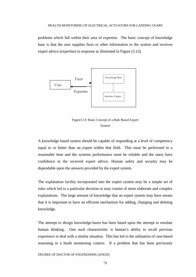
HEALTH MONITORING OF ELECTRICAL ACTUATORS FOR LANDING GEARS
DEGREE OF DOCTOR OF ENGINEERING (ENGD)
78
problems which fall within their area of expertise. The basic concept of knowledge
base is that the user supplies facts or other information to the system and receives
expert advice (expertise) in response as illustrated in Figure (3.13).
Figure3.13: Basic Concept of a Rule Based Expert
System
A knowledge based system should be capable of responding at a level of competency
equal to or better than an expert within that field. This must be performed in a
reasonable time and the systems performance must be reliable and the users have
confidence in the received expert advice. Human safety and security may be
dependable upon the answers provided by the expert system.
The explanation facility incorporated into the expert system may be a simple set of
rules which led to a particular decision or may consist of more elaborate and complex
explanations. The large amount of knowledge that an expert system may have means
that it is important to have an efficient mechanism for adding, changing and deleting
knowledge.
The attempt to design knowledge-bases has been based upon the attempt to emulate
human thinking. One such characteristic is human’s ability to recall previous
experience to deal with a similar situation. This has led to the utilisation of case-based
reasoning in a heath monitoring context. If a problem that has been previously
User
Facts
Expertise
Knowledge Base
Interface Engine
HEALTH MONITORING OF ELECTRICAL ACTUATORS FOR LANDING GEARS
DEGREE OF DOCTOR OF ENGINEERING (ENGD)
79
diagnosed by the expert system it will store the information for use if a similar event
re-occurs. Therefore the diagnosis can be completed by simply recalling the previous
solution.
3.11.3 Neural Networks
Artificial Neural Networks (ANN) belongs to a family of numerical learning
techniques. They are models which are designed to emulate a biological neural
network. The inputs which the artificial neuron receives are analogue to the
electrochemical impulses that biological neurons receive from other neurons.
Practically they are however much simpler than biological ones so it is not expected
for them to produce the sophisticated behaviour of humans. They can however
perform certain tasks very effectively in particular classifications.
The artificial neural network is built up of individual nodes which each independently
perform a simple computation. This means that neural networks have a highly parallel
structure allowing them to explore many competing hypothesis simultaneously. The
most commonly used neural network is the Multi-Layer Perceptron (MLP) network
which is composed of an input layer, a number of hidden layers and output nodes. The
processing is done at each node (neuron) and consists of multiplying each input by a
weight, adding the weighted inputs together and passing the sum through a sigmoid
activation function.
Many authors have focused on the use of neural networks in health monitoring
applications for solving fault detection and isolation tasks such as in industrial
processes (Patan and Parisini 2005; Koeppin-Seliger and Frank 1995; Korbicz and
Janczak 2002).
3.11.4 Fuzzy Systems
Whilst probability theory is useful and works well in measuring what the likelihood of
a hypothesis is it will not say anything about the meaning of the hypothesis. Fuzzy
logic (also known as possibility theory) can address this problem providing a
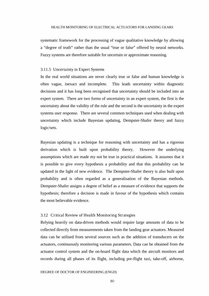
HEALTH MONITORING OF ELECTRICAL ACTUATORS FOR LANDING GEARS
DEGREE OF DOCTOR OF ENGINEERING (ENGD)
80
systematic framework for the processing of vague qualitative knowledge by allowing
a “degree of truth” rather than the usual “true or false” offered by neural networks.
Fuzzy systems are therefore suitable for uncertain or approximate reasoning.
3.11.5 Uncertainty in Expert Systems
In the real world situations are never clearly true or false and human knowledge is
often vague, inexact and incomplete. This leads uncertainty within diagnostic
decisions and it has long been recognised that uncertainty should be included into an
expert system. There are two forms of uncertainty in an expert system, the first is the
uncertainty about the validity of the rule and the second is the uncertainty in the expert
systems user response. There are several common techniques used when dealing with
uncertainty which include Bayesian updating, Dempster-Shafer theory and fuzzy
logic/sets.
Bayesian updating is a technique for reasoning with uncertainty and has a rigorous
derivation which is built upon probability theory. However the underlying
assumptions which are made my not be true in practical situations. It assumes that it
is possible to give every hypothesis a probability and that this probability can be
updated in the light of new evidence. The Dempster-Shafer theory is also built upon
probability and is often regarded as a generalisation of the Bayesian methods.
Dempster-Shafer assigns a degree of belief as a measure of evidence that supports the
hypothesis; therefore a decision is made in favour of the hypothesis which contains
the most believable evidence.
3.12 Critical Review of Health Monitoring Strategies
Relying heavily on data-driven methods would require large amounts of data to be
collected directly from measurements taken from the landing gear actuators. Measured
data can be utilised from several sources such as the addition of transducers on the
actuators, continuously monitoring various parameters. Data can be obtained from the
actuator control system and the on-board flight data which the aircraft monitors and
records during all phases of its flight, including pre-flight taxi, take-off, airborne,

HEALTH MONITORING OF ELECTRICAL ACTUATORS FOR LANDING GEARS
DEGREE OF DOCTOR OF ENGINEERING (ENGD)
81
landing and post-flight taxi, data is also available through the aircrafts Built In Tests
(BIT). Applying data driven methods such as neural networks to actuator fault
diagnostics can provide good and accurate decisions, they are extremely good at
pattern classification but are generally regarded as ‘black box’, they are therefore only
focused on inputs and outputs and do not allow the internal logic to be accessed and
inspected. This leads to difficulties in justifying maintenance decisions to aircraft
operators due to the large financial losses that can be occurred when incorrectly
grounding aircraft and the risk to passenger safety if the decision to fly the aircraft is
wrong. There is therefore the need to provide justifications reasons for a decision.
Due to legislations and aircraft construction requirements the use of sensor equipment
can be limited, for example in landing gears where weight minimisation is currently
the major driving force, large sensor arrays are not possible. They add complexity,
weight and volume to the system and require power, calibration, wiring and
processing time. The use of existing flight data will help reduce the need for
additional sensor equipment and can provide important information on the actuators
operating conditions. Flight data can also be incorporated into dynamic landing gear
loading models, reducing the need for load measuring sensors. Due to the various
operating modes, often threshold levels can be breached even though no fault has
occurred. Flight data can be particularly useful in deducing if the observed symptoms
originate due to the actuator’s operating mode or through any impending failures.
Model-based health management of the landing gear actuators can offer robust early
fault detection and is based upon accurately modelling the dynamics of the actuator
system. The use of dynamic modelling techniques is an attractive approach to health
monitoring for the electric landing gear actuator system. For example, the actuators
do not require complicated modelling and can provide fault diagnosis relating to the
systems physical states or parameters. The ability to model failure progression further
enhances confidence in fault classification and has been shown to be able to
distinguish between gear and bearing failure modes for electromechanical actuators
used in a variety of other applications. They offer a non-intrusive approach, requiring

HEALTH MONITORING OF ELECTRICAL ACTUATORS FOR LANDING GEARS
DEGREE OF DOCTOR OF ENGINEERING (ENGD)
82
little addition sensor equipment incorporated into the landing gear system by acting
only upon command and response data obtained through the control systems. Data
driven methods however do not require system modelling, this creates faster algorithm
processing time than that which is required for models, the use of models can provide
better actuator fault diagnostics but at the cost of higher computational needs.
Rule-based systems encompass a set of rules which can be encoded similar to human
logic. This leads to transparency in any health assessment, a crucial factor in
decisions relating to aerospace maintenance. Case-based reasoning approaches are
often used when a rule base would be too large to construct or model-based
diagnostics are impractical. Case-based diagnostic reasoning is particularly useful at
capturing qualitative information which can be incorporated into the system and
decisions be made based on past case history (Frank 1990). Incorporating case based
reasoning into the health monitoring system, can be designed as fault trees. This
allows maintenance engineers to take an event which occurs at the platform level and
using extracted features from signals, knowledge of past events, and actuator usage
data, then a logical progression can be followed through the system and subsystem
levels to arrive at possible component faults (Raheja et al. 2006).
With the issues outlined earlier, in order to achieve the best possible level of reliability
in a monitoring system, health management can be achieved through extracting
information from a combination of sources and techniques. For example, data patterns
relating to known information can be provided through the combination of monitored
data, knowledge and models. Such approaches are gaining popularity in
electromechanical actuator health monitoring within the aerospace industry due to the
ability to achieve auditable and robust decisions (Keller et al. 2006; Watson and
Byington 2006). Figure (3.14) illustrates this monitoring concept.
HEALTH MONITORING OF ELECTRICAL ACTUATORS FOR LANDING GEARS
DEGREE OF DOCTOR OF ENGINEERING (ENGD)
83
Figure 3.14: Health Monitoring Concept Based on
Multiple Strategies
3.13 Motor-Driven Actuator Health Monitoring Review
3.13.1 Overview
The electric actuators which are the focus of this research must be robust and reliable
to avoid potential risk of accidents. Aerospace lags behind in the use of electric
actuators whereas other industries such as automotive, rail and process industries have
used these drives for many years. Much of the applications in these industries are just
as cost and safety critical as they are in aerospace. In aerospace actuation systems are
used for primary and secondary flight controls; braking, cargo doors, pressure valves,
weapons systems and landing gear extension and retraction. Most of which are
critical for the successful and safe operation of the aircraft.
In the automotive industry electric motor driven actuation is now commonplace. Such
applications include electric windows, locks, aerials and seat/lamp/mirror adjustments.
Drive-by-wire introduces motor-actuated steering and the starting circuit is a heavy
motor-driven actuation system. The rail industry actuators are one such application of
electrical actuation is in railway points. These are mechanical devices that allow a
train to move from one set of tracks to another. Point mechanisms are track elements
which frequently fail causing delays and increased costs. Such failures have also been
MonitoredData
PhysicalModels
ExpertKnowledge
CBMSystem Decisions
HEALTH MONITORING OF ELECTRICAL ACTUATORS FOR LANDING GEARS
DEGREE OF DOCTOR OF ENGINEERING (ENGD)
84
known to cause fatal accidents. The principle components of these point mechanisms
must be reliable and are subject to extreme environmental changes, varying loads,
stresses and very large mechanical forces. Modern power/process plants and motor
driven process control valves which control fluid-circulating systems are a regular
feature. These control valves are essential for plant operation and safety. A loss of
these systems can have catastrophic consequences. This section will review some
key health monitoring systems and techniques which have been developed specifically
for the monitoring of electrical actuation in the aerospace, automotive, rail and power
industry.
3.13.2 Aerospace
The use of model-based fault detection schemes based upon the use of parameter
estimation for use in both on-line and off-line diagnosing of actuator faults has been
demonstrated as an intuitive and non-intrusive approach (Moseler and Isermann 1998,
2000). This was further developed as a monitoring application for an air pressure
opening and closing valve in a passenger aircraft operated by a DC motor driven
actuator (Juricic et al. 2001). The model-based approach here was based upon the use
of parity equations supported by an approximate reasoning technique known as the
Transfer Belief Model (TBM) (Smets and Kennes 1994) which helped achieve high
diagnostic resolution, stability and accuracy over more traditional Boolean logic
methods. The use of a model–based fault detection scheme to support the reliability
of electromechanical replacements for civil aircraft engine actuators was also used by
Dixon and Pike (2002). It was shown that by measuring key parameters and testing
them against pre-determined baselines, the use of a fuzzy logic change detector and
fault classifier yielded promising results on determining significant parameter
changes.
Byington et al. (2004a) as part of the REACTS project developed a health
management methodology for the health monitoring of electrical flight control
actuators. They showed that model-based methods for prognosis and health
management offered a means for robust health monitoring and early fault detection.
HEALTH MONITORING OF ELECTRICAL ACTUATORS FOR LANDING GEARS
DEGREE OF DOCTOR OF ENGINEERING (ENGD)
85
Byington et al.( 2004b) furthered this health monitoring strategy for application for the
health management of the F/A-18 stabilator electro-hydraulic servo valves. The
development of this methodology took into consideration sensor and processing
limitations for onboard implementation. It made use of processing the
command/response signals and hydraulic pressure data along with neural networks,
automated reasoning, classification and advanced knowledge fusion to provide a real-
time assessment of the current and future actuator health.
The Kennedy Space Centre concerned with the health of mission critical
electromechanical actuator systems developed a valve health monitoring system
(Perotti et al. 2006). This system based upon a smart current signature sensor that
monitors the valves in a nonintrusive way. In the development of this the effects of
external features on the algorithm were analysed. It was highlighted that fluctuating
temperatures had an effect on all of the extracted features and there are further
challenges in regard to parameter nonlinearity.
3.13.3 Automotive
The health monitoring of a diesel engine coolant mechanisms was achieved by
Twiddle and Jones (2002) through the use a few low cost sensors. Residuals were
generated by system models and extracted features classified through fuzzy rules as
part of an overall engine health management system. In a car the air mass flow
through the intake manifold into the cylinders is controlled by a DC motor driven
throttle valve actuator. These must operate robustly and reliably because any
malfunction can cause unintentional stopping of the engine. The application of a
neuro-fuzzy hybrid system for the diagnosis of technical faults in such a throttle valve
actuator has been addressed by Pfeufer et al. (1997). This used a knowledge base in
the form of rules making the diagnosis understandable to human operators. It was
found that the use of a neuro-fuzzy system could significantly enhance the mapping of
observed symptoms to the underlying faults through the use of a parameterised logical
operator.
HEALTH MONITORING OF ELECTRICAL ACTUATORS FOR LANDING GEARS
DEGREE OF DOCTOR OF ENGINEERING (ENGD)
86
It is quite possible in a system that multiple failures in both the actuators and sensors
may occur simultaneously further complicating any fault diagnosis and isolation. Hsu
et al. (1995) uses a hexadecimal decision table to relate all possible identified failure
patterns to the residual code. This was successfully applied both in simulations and
experimental work. However the performance of the diagnostic system was degraded
with the presence of noise and system uncertainty.
3.13.4 Rail
Since various major rail accidents in Europe over the past few decades a provision of a
reliable infrastructure has become paramount in achieving good levels of safety. The
rail industry has always searched for new means to improve the performance of
subsystems to ensure both safety and reliability of services. One such subsystem is
railway points. Point mechanisms are track elements which frequently fail causing
delays and increased costs. Such failures have also been known to cause fatal
accidents. Roberts et al. (2002) considered a case study of an electro-pneumatic
railway point machine and proposed a fault detection and isolation process across an
interconnected geographical area. This used field bus data communication networks
allowing fault detection and isolation to be achieved on a number of close proximity
assets. Fault detection was based upon abstract static models. Fault isolation was
achieved through the use of a neuro-fuzzy system.
Oyebande and Renfrew (2002) used a net energy analysis technique relying upon
measured armature current and voltage waveforms and developed a system for the
health monitoring of point mechanisms which uses a large range of measured data
including distances, driving force, current and voltage, electrical noise, temperature
and state changes. The use of Finite Impulse Response (FIR) systems based upon a
normH 2 criterion was used by Zattoni (2006) as a means for guaranteeing
robustness with respect to disturbance inputs. This proposed algorithm could be used
HEALTH MONITORING OF ELECTRICAL ACTUATORS FOR LANDING GEARS
DEGREE OF DOCTOR OF ENGINEERING (ENGD)
87
for successful incipient fault detection for systems where the actuators operation could
with sufficient accuracy be described by linear time invariant models.
Wear is one of the most important factors affecting rail point mechanisms. Garcia
Marquez et al. (2003) put forward a model for the remote health monitoring of rail
mechanisms and highlighted the need for models to adapt to dynamic external
environments. This was applied to a predictive maintenance system known as RCM²
(Marquez et al. 2003). Further algorithms were put forward including the use of
Kalman filtering (Marquez et al. 2007) and the development of unobserved
component models approach for detecting wear and the behaviour of a worn set of
points based. The model was used to search for significant correlations between a
reference signal and new information coming in from critical components updating
model parameters on a continuous basis.
3.13.5 Power Industry
A common component found in modern power plants and process plants such as in
the petrochemical or nuclear industry are control valves which control fluid-
circulating systems. These valves are often driven by pneumatic actuators but are
being replaced with electromechanical drives. These control valves are essential for
plant operation and safety. A loss of these systems can have catastrophic
consequences. It has been shown that the use of motor current signature analysis can
be a selective and early indicator of developing mechanical and electrical
abnormalities in actuated valves and is becoming a commonly used technique. Non-
intrusive methods based upon motor current signature analysis have been proposed by
as part of an expert system for use in preventative maintenance in nuclear power
stations (Mukhopadhyay and Chaudhuri 1995). On-line health monitoring and using
electrical measurements to estimate the electric torque of the induction motor attached
to the MOV was outlined in Chai et al. (2004). This was reviewed against current
signature and power signature methods and was shown to have advantages including
better resolution, accuracy and sensitivity to load changes which are very useful in the
HEALTH MONITORING OF ELECTRICAL ACTUATORS FOR LANDING GEARS
DEGREE OF DOCTOR OF ENGINEERING (ENGD)
88
early detection of faults. A model free on-line fault detection technique based upon a
spectral analysis technique known as the Squared Coherency Function designed to be
sensitive to disturbances in plant dynamics was used by Previdi and Parisini (2006) to
provide effective actuator fault detection.
3.14 Conclusion
There are typically three kinds of maintenance regimes, time-based preventative, run-
to-failure and condition based maintenance. The potential benefits of moving towards
condition based maintenance is based around the concept of optimisation of
maintenance scheduling. These include reducing the lifetime costs of a machine or
system, minimising the effects upon the environment and increasing safety to
personnel. The design of a condition based maintenance system is application specific
and a strategy should be adopted that incorporates condition based maintenance into
systems rather than systems into condition based maintenance. This strategy should
be systems based and follow a logical progression from design and trade studies,
where the objectives and requirements are used to select appropriate equipment and
monitoring strategies, through to experimental testing, algorithm refinement and
implementation.
The uses of sensors are fundamental to a condition based maintenance system and
must be selected carefully to ensure the system meets the specific performance
requirements. The number of sensors introduced into a system requires consideration
to be given to aspects such as costs and complexity. Sensor networks can provide a
reduction in measurement time, and therefore reduce costs. Increased numbers of
sensors however require more computational effort and add complexity to a system.
System complexity can have adverse effects upon the reliability of the system, the
higher the number of components, the higher the number and frequency of possible
failures. These factors require a trade-off between sensor numbers and system level
requirements.

HEALTH MONITORING OF ELECTRICAL ACTUATORS FOR LANDING GEARS
DEGREE OF DOCTOR OF ENGINEERING (ENGD)
89
There exists a large tool box of health monitoring techniques, the most popular of
which are vibration analysis, wear debris analysis, motor current analysis and
performance analysis. Each of these techniques offers particular advantages and
disadvantages depending on the application. The most popular strategies for decision
reasoning are confined to the domain of expert systems. These are classified as data
driven or knowledge driven. A fusion of these approaches however can limit
uncertainty and maximise their decision making abilities.
Health monitoring of electrical actuation systems is not a new topic but nor is it a fully
advanced subject. As electrical actuation sees more and more introductions in the
aerospace, automotive, rail and process and power industries in safety critical
applications, numerous combinations of mature health monitoring techniques are
being applied to electrical actuation. In the aerospace industry there appears to be a
strong reliance upon transparent dynamical models. The automotive industry where
decision justifications are not so necessary utilise heavily neural networks. The rail
and process industry where limitations on sensors are not as paramount as in
aerospace rely heavily on signal processing methods.
3.15 References
Abidin, M.S.Z., Yusof, R., Kahlid, M., Amin, S. (2002), 'Application of a model-
based fault detection and diagnosis using parameter estimation and fuzzy inference to
a DC-servomotor', Proceedings of the 2002 IEEE International Symposium on
Intelligent Control, pp.783-787
Benbouzid, M.E.H. (2000), 'Review of induction motors signature analysis as a
medium for faults detection', IEEE Transactions on Industrial Electronics, Vol 47, No
5, pp. 984-993.
Bovio, I., Lecce, L. (2006), 'Health Monitoring of aeronautical structures based on
vibrations measurements', International Society for Optical Engineering,
HEALTH MONITORING OF ELECTRICAL ACTUATORS FOR LANDING GEARS
DEGREE OF DOCTOR OF ENGINEERING (ENGD)
90
Busch-Vishniac, I.J. (1999), 'Electromechanical sensors and actuators'
Byington, C., Safa-Bakhsh, R., Watson, M., Kalgren, P. (2003),'Metrics evaluation
and tool development for health and usage Monitoring technology'. in AHS Forum.
Phoenix Arizona.
Byington, C.S. (2006), 'Recent case studies in bearing fault detection and prognosis',
IEEE Aerospace Conference.
Byington, C.S., Watson, M., Edwards, D., Stoelting, P. (2004), 'A model-based
approach to prognostics and health management for flight control actuators', Big Sky,
MT, United States: Institute of Electrical and Electronics Engineers Computer
Society, Piscataway, NJ 08855-1331, United States.
Byington, C.S., Watson, M., Edwards, D., (2004), 'Data-driven neural network
methodology to remaining life predictions for aircraft actuator components', in IEEE
Aerospace Conference Proceedings.
Chai, J., Kang, S., Park, S., Hong, S., Lim, C. (2004), 'Condition monitoring of a
motor-operated valve using estimated motor torque', JSME International Journal,
Series C: Mechanical Systems, Machine Elements and Manufacturing, Vol 47, No 1,
pp.305-313.
Crowther, A., Zhang, N. (2003), 'Powertrain Vibration Analysis Using Torsional
Finite Elements', in The 10th Asia-Pacific vibration Conference, Gold Coast,
Australia.
De Silva, C.W. (1989), 'Control sensors and actuators'

HEALTH MONITORING OF ELECTRICAL ACTUATORS FOR LANDING GEARS
DEGREE OF DOCTOR OF ENGINEERING (ENGD)
91
Dixon, R., Pike, A.W. (2002), 'Application of condition monitoring to an
electromechanical actuator: A parameter estimation based approach', Computing and
Control Engineering Journal, Vol 13, No 3, pp71-81.
El Faouzi, N. (2004), 'Data fusion in road traffic engineering: an overview', SPIE-Int.
Soc. Opt. Eng.
Engel, S.J., et al. (2000), 'Prognostics, the real issues involved with predicting life
remaining', 2000. Big Sky, MT.
Eren, L., Devaney, M., J. (2002), 'Bearing damage detection via wavelet packet'
Anchorage, AK, USA: IEEE.
Esteban, J., et al., (2005), 'A review of data fusion models and architectures: towards
engineering guidelines', Neural Computing Applications, Vol 14, No 4, pp. 273-81.
Fraden, J., (1993), 'AIP handbook of modern sensors: physics, designs and
applications',
Frank, P.M., (1990), 'Fault diagnosis in dynamic systems using analytical and
knowledge-based redundancy: A survey and some new results', Automatica, Vol 26,
No 3, pp. 459-474.
Garcia Marquez, Schmid, F., Collado, J. (2003), 'Wear assessment employing remote
condition monitoring: A case study', Wear, Vol 255, No 7-12, pp. 1209-1220.
Garcia Marquez, F.P., Schmid, F., Collado, J., (2003), 'A reliability centred approach
to remote condition monitoring. A railway points case study', Reliability Engineering
and System Safety, Vol 80, No 1, pp. 33-40.

HEALTH MONITORING OF ELECTRICAL ACTUATORS FOR LANDING GEARS
DEGREE OF DOCTOR OF ENGINEERING (ENGD)
92
Garcia Marquez, F.P., Schmid, F., (2007), 'A digital filter-based approach to the
remote condition monitoring of railway turnouts', Reliability Engineering and System
Safety, Vol 92, No 6, pp. 830-840.
Garcia Marquez, F.P., Pedregal Tercero, D.J. Schmid, F., (2007), 'Unobserved
Component models applied to the assessment of wear in railway points: A case study',
European Journal of Operational Research, Vol 176, No 3, pp. 1703-1712.
Hammouri, H., Kinnaert, M., El Yaagoubi, E.H. (1999), ' Observer-based approach to
fault detection and isolation for nonlinear systems', IEEE Transactions on Automatic
Control, Vol 44, No 10, pp. 1879-84.
Harris-Jones, C., (1995), 'Knowledge based systems methods', The Practitioner
Series, Prentice Hall.
Hood, A., Pines, D. (2001), 'Feasibility of a linear phased acoustic array for health
monitoring of gears', Society of Photo-Optical Instrumentation Engineers, Newport
Beach, CA:
Hopgood, A. (1993), 'Knowledge-based systems for engineers and scientists', CRC
Press, Inc.
Hountalas, D. (1999), 'Development and Application of a Fully Automatic
Troubleshooting method for Large Marine Diesel Engines', Applied Thermal
Engineering, Vol 19, pp. 299-324.
Hsu, P.-L., Lin, K.-L. Shen, L.-C. (1995), 'Diagnosis of multiple sensor and actuator
failures in automotive engines', IEEE Transactions on Vehicular Technology, Vol 44,
No 4, pp. 779-789.

HEALTH MONITORING OF ELECTRICAL ACTUATORS FOR LANDING GEARS
DEGREE OF DOCTOR OF ENGINEERING (ENGD)
93
Ignizio, J. (1991), Iintroduction to expert systems: The development and
implementation of rule-based expert systems', McGraw-Hill, Inc.
Isermann, R. (2005), 'Model-based fault-detection and diagnosis - Status and
applications', Annual Reviews in Control, Vol 29, No 1, pp. 71-85.
Iyengar, S., Sastry, S., Balakrishnan, N. (2003), 'Foundations of data fusion for
automation', IEE Instrumentation & Measurement Magazine, Vol 6, No4, pp.35-41
Jardine, A.K.S., Lin, D., Banjevic, D. (2006), 'A review on machinery diagnostics and
prognostics implementing condition-based maintenance', Mechanical Systems and
Signal Processing, Vol 20, No 7, p. 1483-1510.
Juricic, D., Moseler, O., Rakar, A. (2001), 'Model-based condition monitoring of an
actuator system driven by a brushless DC motor', Control Engineering Practice, Vol 9,
No 5, pp. 545-554.
Keller, K., (2006), 'Aircraft electrical power systems prognostics and health
management' in IEEE Aerospace Conference,
Kacprzynski, G., Roemer, M., Hess, A., (2002), 'Health Management System Design:
Development, Simulation and Cost/Benefit Optimization', IEE
Kammer, D., (1991), 'Sensor Placement for on-orbit modal identification and
correlation of large space structures', Journal of Guidance, Control and Dynamics,
Vol 14, pp. 251-259.
Kanoun, O., trankler, H., (2004), 'Sensor technology advances and future trends',
IEEE Transactions on Instrumentation and Measurement, Vol 53, No 6, pp. 1497-
1501.
HEALTH MONITORING OF ELECTRICAL ACTUATORS FOR LANDING GEARS
DEGREE OF DOCTOR OF ENGINEERING (ENGD)
94
Khan, M.A., Starr, A., Cooper, D., (2008), 'A methodology for online wear debris
morphology and composition analysis', Proceedings of the Institution of Mechanical
Engineers, Part J: Journal of Engineering Tribology, Vol 222, No 7, pp. 785-796.
Khan, M.A., Starr, A., (2006), 'Wear debris: Basic features and machine diagnostics',
Insight: Non-Destructive Testing and Condition Monitoring, Vol 48, No 8, pp. 470-
476.
Kliman, G., Stein, J., (1992), 'Methods of motor current signature analysis', Electric
Machines and Power Systems, Vol 20, No 5, pp. 463-474.
Koeppen-Seliger, B., Frank. P., (1995), 'Fault detection and isolation in technical
processes with neural networks', New Orleans, LA, USA: IEEE, Piscataway, NJ,
USA.
Korbicz, J., Janczak, A., (2002), 'Artificial neural network models for fault detection
and isolation of industrial processes', Computer Assisted Mechanics and Engineering
Sciences, Vol 9, No 1, pp. 55-69.
Kothamasu, R., Huang, S., Verduin, W. (2006), 'System health monitoring and
prognostics - A review of current paradigms and practices', International Journal of
Advanced Manufacturing Technology, Vol 28, No 9, pp. 1012-1024.
Linas, J., Hall, D. (1998), 'An introduction to multi-sensor data fusion', Monterey, CA,
USA: IEEE.
Luo, R., Lin, M., and Scherp, R. (1988), 'Dynamic multi-sensor data fusion system for
intelligent robots', IEEE Journal of Robotics and Automation, Vol 4. No4, pp. 386-
396

HEALTH MONITORING OF ELECTRICAL ACTUATORS FOR LANDING GEARS
DEGREE OF DOCTOR OF ENGINEERING (ENGD)
95
Montalvao, D., Maia, N., Ribeiro, A., (2006), 'A review of vibration-based structural
health monitoring with special emphasis on composite materials', Shock and Vibration
Digest, Vol 38, No 4, pp. 295-324.
Moseler, O., Isermann, R. (2000), 'Application of model-based fault detection to a
brushless DC motor', IEEE Transactions on Industrial Electronics, Vol 47, No 5, pp.
1015-1020.
Moseler, O., Isermann, R. (1998), 'Model-based fault detection for brushless dc motor
using parameter estimation', Aachen, Ger: IEEE Comp Soc, Los Alamitos, CA, USA.
Mukhopadhyay, S., Chaudhuri, S. (1995), 'A feature-based approach to monitor
motor-operated valves used in nuclear power plants', IEEE Transactions on Nuclear
Science, Vol 42, No 6, pp. 2209-2220.
Nandi, S., Toliyat, H., Xiaodong, L. (2005), 'Condition monitoring and fault
diagnosis of electrical motors-a review', IEEE Transactions on Energy Conversion,
Vol 20, No 4, pp. 719-29.
Orsagh, R., Roemer, M. (2000), 'Development of metrics for mechanical diagnostic
technique qualification and validation', in COMADEM. Houston, TX.
Oyebande, B., Renfrew, A., (2002), 'Condition monitoring of railway electric point
machines', IEE Proceedings: Electric Power Applications, Vol 149, No 6, pp. 465-
473.
Padula, S., Kincaid, R., (1999), 'Optimization strategies for sensor and actuator
placement', NASA Report.

HEALTH MONITORING OF ELECTRICAL ACTUATORS FOR LANDING GEARS
DEGREE OF DOCTOR OF ENGINEERING (ENGD)
96
Pantelelis, N., Kanarachos, A., Gotzias, N., (2001), 'Neural networks and simple
models for the fault diagnostics of naval turbochargers', Mathematics and Computers
in Simulation, Vol 51, pp. 387-397.
Patan, K., Parisini, T. (2005), 'Identification of neural dynamic models for fault
detection and isolation: The case of a real sugar evaporation process', Journal of
Process Control, Vol 15, No 1, pp. 67-79.
Pattichis, C., Pattichis, M., Micheli-Tzanakou, E. (2001), 'Medical imaging fusion
applications: An overview', Institute of Electrical and Electronics Engineers
Computer Society, Pacific Grove, CA:
Patton, R., Chen, J., (1997), 'Observer-based fault detection and isolation: robustness
and applications', Control Engineering Practice, Vol 5, No 5, pp. 671-82.
Patton, R., Chen, J., 'Review of parity space approaches to fault diagnosis', Baden-
Baden, Ger: Publ by Pergamon Press Inc, Tarrytown, NY, USA.
Pedregal, D., Carnero, M. (2006), 'State space models for condition monitoring: A
case study', Reliability Engineering and System Safety, Vol 91, No 2, pp. 171-180.
Perotti, J., Lucena, A., Burns, B. (2006), 'Smart actuators - Valve Health Monitor
(VHM) system', Kissimmee, FL, United States: International Society for Optical
Engineering, Bellingham WA, WA 98227-0010, United States.
Pfeufer, T., Ayoubi, M. (1997), 'Application of a hybrid neuro-fuzzy system to the
fault diagnosis of an automotive electromechanical actuator', Fuzzy Sets and Systems,
Vol 89, No 3, pp. 351-360.
Phillips, P., Diston, D., Payne, J., Pandya, S., Starr, A. (2008), 'The application of
condition monitoring methodologies for certification of reliability in electric landing
HEALTH MONITORING OF ELECTRICAL ACTUATORS FOR LANDING GEARS
DEGREE OF DOCTOR OF ENGINEERING (ENGD)
97
gear actuators', in The 5th International Conference on Condition Monitoring and
Machine Failure Technologies. Edinburgh, UK
Pietruszkiewicz, R., Starr, A., Albarbar, A. Mattheys, R. (2006), 'Remote sensing in
condition monitoring' in 1st World Congress on Engineering Asset Management, Gold
Coast, Australia.
Poyhonen, S., Jover, P., Hyotyniemi. H., (2004), 'Signal processing of vibrations for
condition monitoring of an induction motor', Institute of Electrical and Electronics
Engineers Inc., New York, United States.
Previdi, F., Parisini, T. (2006), 'Model-free actuator fault detection using a spectral
estimation approach: The case of the DAMADICS benchmark problem', Control
Engineering Practice, Vol 14. No 6, pp. 635-644.
Raheja, D., et al., (2006), 'Data fusion/data mining-based architecture for condition-
based maintenance', International Journal of Production Research, Vol 44, No 14, pp.
2869-2887.
Rajagopalan, S., et al. (2004), 'Diagnosis of potential rotor faults in brushless DC
machines', Institution of Electrical Engineers, United Kingdom.
Rajagopalan, S., et al. (2006), 'Current/Voltage-based detection of faults in gears
coupled to electric motors', IEEE Transactions on Industry Applications, Vol 42, No
6, pp. 1412-1420.
Rao, B. (1996), 'The handbook of condition monitoring' 1st ed. Elsevier Advanced
Science Ltd.

HEALTH MONITORING OF ELECTRICAL ACTUATORS FOR LANDING GEARS
DEGREE OF DOCTOR OF ENGINEERING (ENGD)
98
Roberts, C., et al. (2002), 'Distributed quantitative and qualitative fault diagnosis:
Railway junction case study', Control Engineering Practice, Vol 10, No 4, pp. 419-
429.
Zhou, F.B., et al. (2002), 'Remote condition monitoring for railway point machine',
Institute of Electrical and Electronics Engineers Inc. Washington, DC:
Roemer, M., Kacprzynski, G. (2000), 'Advanced diagnostics and prognostics for gas
turbine engine risk assessment', in IGTI/ASME Turbo Expo, Munich, Germany.
Saniger, J., et al. (2001), 'Structural health monitoring methodology for aircraft
condition based maintenance', Society of Photo-Optical Instrumentation Engineers.
Schoen, R., Habetler, T. (1995), 'Effects of time-varying loads on rotor fault detection
in induction machines', IEEE Transactions on Industry Applications, Vol 31, No 4,
pp. 900-906.
Sen, A., Murty A., (1999), 'Parallel processing application in traction motor fault
diagnosis', Electrical power Systems Research, Vol 52, pp. 241-249.
Smets, P., Kennes, R. (1994), 'Transferable belief mode', Artificial Intelligence, Vol
66, No 2, pp. 191-234.
Starr, A., Willets, R., Hannah, P., Banjevic, D., Jardine, A. (2002a), 'Data fusion
applications in intelligent condition monitoring', Recent Advances in Computers,
Computing and Communications, pp. 110-115.
Starr, A., Hannah, P., Esteban, J., Willets, R. (2002b), 'Data fusion as a model for
advanced condition-based maintenance', Insight-Non-Destructive Testing and
Condition Monitoring, Vol 44, No 8, pp. 503-507.
HEALTH MONITORING OF ELECTRICAL ACTUATORS FOR LANDING GEARS
DEGREE OF DOCTOR OF ENGINEERING (ENGD)
99
Starr, A. (2005), 'Merging condition monitoring data and knowledge: fusion and
neural approaches', in Maintenance, Condition Monitoring and Diagnostics, POHTO,
Oulu, Finland, POHTO.
Starr, A., Albarbar, A., Pietruszkiewicz, R., Mekid, S., (2007), 'Developments in
wireless sensing for condition monitoring', Condition Monitor,
Steinberg, A., Bowman, C., White, F. (1999), 'Revisions to the JDL data fusion
model', Proc. SPIE Algorithms: Issues and Approaches II, Vol 37
Swearingen, K., et al. (2007), 'An open system architecture for condition based
maintenance overview', Institute of Electrical and Electronics Engineers Computer
Society, Piscataway, NJ 08855-1331, United States.
Thomson, W., Fenger, M. (2001), 'Current signature analysis to detect induction
motor faults', IEEE Industry Applications Magazine, Vol 7, No 4, pp. 26-34.
Twiddle, J., Jones, N. (2002), 'Fuzzy model-based condition monitoring and fault
diagnosis of a diesel engine cooling system', Proceedings of the Institution of
Mechanical Engineers. Part I: Journal of Systems and Control Engineering, Vol 216,
No 3, pp. 215-224.
Vachtsevanos, G., Lewis, F., Roemer, M., Hess, A., WU, B. (2006), 'Intelligent Fault
Diagnosis and Prognosis for Engineering Systems' John Wiley & Sons , INC.
Watson, M., Byington, C. (2006), 'Improving the maintenance process and enabling
prognostics for control actuators using CAHM software', Institute of Electrical and
Electronics Engineers Computer Society, Piscataway, United States.
HEALTH MONITORING OF ELECTRICAL ACTUATORS FOR LANDING GEARS
DEGREE OF DOCTOR OF ENGINEERING (ENGD)
100
Wu, Y. (2009), 'Misalignment diagnosis of rotating machinery through vibration
analysis via the hybrid EEMD and EMD approach', Smart Materials and Structures,
Vol 18, No 9.
Zattoni, E. (2006), 'Detection of incipient failures by using an H2- norm criterion:
Application to railway switching points', Control Engineering Practice, Vol 14, No 8,
pp. 885-895.
Zhongming, Y., Bin, W., Sadeghian, A. (2003), 'Current signature analysis of
induction motor mechanical faults by wavelet packet decomposition', IEEE
Transactions on Industrial Electronics, Vol 50, No 6, pp. 1217-28.
HEALTH MONITORING OF ELECTRICAL ACTUATORS FOR LANDING GEARS
DEGREE OF DOCTOR OF ENGINEERING (ENGD)
101
C h a p t e r 4 : U n d e r s t a n d i n g t h e C o m m e r c i a lB e n e f i t s o f A e r o s p a c e H e a l t h M o n i t o r i n g
4.1 Introduction
There are a number of questions that must be addressed before a realistic commercial
strategy for aerospace actuator health monitoring can be proposed. These include
providing definitions on the customer, the supply chain networks and any supporting
technologies. But most importantly, what the commercial drivers are? It is important,
that there is a clearly identified need for the actuator health monitoring. If there is no
existing need then any attempt for marketing health monitoring as a necessary future
technological requirement is doomed for failure.
In this chapter the commercial need for actuator health monitoring is explored in the
context of the role of health monitoring in the changing aerospace maintenance
industry. Focuses on the reasons behind changes to the maintenance market and the
drive towards innovative maintenance support concepts is discussed at length. This
discussion includes the key benefits and value potential of predictive maintenance and
through life support of aerospace products. Challenges to integrating new monitoring
technologies into existing products are identified as extending to not only technical
challenges but also challenges to commercial integration. A number of pricing
strategies are explored in the context of commercial integration, and finally a SWOT
analysis of the technology is provided.
4.2 Current Aerospace Maintenance Practice
The airline industry is considered as one of the most unique businesses in the world
which suffers from a variety of complex operations. These include moving aircraft
loaded with passengers and cargo over large distances and the scheduling of flights,
crews and maintenance. These all lead up to substantial costs measured in time and
money. Aircraft maintenance forms an essential part of an aircrafts airworthiness
criteria, with its main objective being to ensure a fully serviced, operational and safe
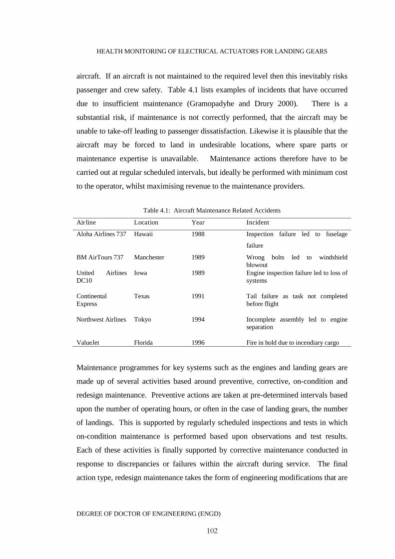
HEALTH MONITORING OF ELECTRICAL ACTUATORS FOR LANDING GEARS
DEGREE OF DOCTOR OF ENGINEERING (ENGD)
102
aircraft. If an aircraft is not maintained to the required level then this inevitably risks
passenger and crew safety. Table 4.1 lists examples of incidents that have occurred
due to insufficient maintenance (Gramopadyhe and Drury 2000). There is a
substantial risk, if maintenance is not correctly performed, that the aircraft may be
unable to take-off leading to passenger dissatisfaction. Likewise it is plausible that the
aircraft may be forced to land in undesirable locations, where spare parts or
maintenance expertise is unavailable. Maintenance actions therefore have to be
carried out at regular scheduled intervals, but ideally be performed with minimum cost
to the operator, whilst maximising revenue to the maintenance providers.
Table 4.1: Aircraft Maintenance Related Accidents
Airline Location Year Incident
Aloha Airlines 737 Hawaii 1988 Inspection failure led to fuselage
failure
BM AirTours 737 Manchester 1989 Wrong bolts led to windshieldblowout
United AirlinesDC10
Iowa 1989 Engine inspection failure led to loss ofsystems
ContinentalExpress
Texas 1991 Tail failure as task not completedbefore flight
Northwest Airlines Tokyo 1994 Incomplete assembly led to engineseparation
ValueJet Florida 1996 Fire in hold due to incendiary cargo
Maintenance programmes for key systems such as the engines and landing gears are
made up of several activities based around preventive, corrective, on-condition and
redesign maintenance. Preventive actions are taken at pre-determined intervals based
upon the number of operating hours, or often in the case of landing gears, the number
of landings. This is supported by regularly scheduled inspections and tests in which
on-condition maintenance is performed based upon observations and test results.
Each of these activities is finally supported by corrective maintenance conducted in
response to discrepancies or failures within the aircraft during service. The final
action type, redesign maintenance takes the form of engineering modifications that are

HEALTH MONITORING OF ELECTRICAL ACTUATORS FOR LANDING GEARS
DEGREE OF DOCTOR OF ENGINEERING (ENGD)
103
made in order to address arising safety or reliability issues, which were unanticipated
in the original design.
Much of the major maintenance and repair work performed on aircraft is provided
through service providers who carry out Maintenance, Repair and Overhaul (MRO)
operations for the aircraft operators. The landing gear is a critical assembly and a
major key to maintaining the overall aircraft value. Operators cannot afford, or are
willing to risk compromising their landing gear MRO activities and will look for the
best combination of affordability, expertise, flexibility and the ability to offer the best
solutions when faced with the choice of MRO provider.
An example of how maintenance support of landing gears would be as follows. In the
event of a series of incidents such as ‘hard landings’ reported by the operators, major
repair operations, or complete gear overhauls will be conducted at a MRO provider’s
maintenance site. The operators themselves can carry out, minor repairs and on-wing
maintenance, also at pre-determined intervals. Once the aircraft has been received at
the MRO maintenance facility, the landing gears will be dismantled and individual
parts will be put through a serious of non-destructive tests. This testing will identify
any developing failures, such as structural fatigues or internal corrosion. The results
of which will determine if the parts are repaired, replaced, scrapped or recycled
(Patkai et. al 2007). Landing gears are complex systems with a vast number of parts o
which need to be maintained and inspected, which results in costly maintenance
operations, in terms of time. An example of key inspection areas along with typical
timescales would be:
1. After 300 hours or after 1 year in service inspection
- Shock absorber Nitrogen Pressure check
2. After 600 hour inspections
- Landing gear hinge points visual inspections
- Leak inspection (oil, hydraulic fluid etc)
HEALTH MONITORING OF ELECTRICAL ACTUATORS FOR LANDING GEARS
DEGREE OF DOCTOR OF ENGINEERING (ENGD)
104
- Inspection of torque link play
3. After 7 years or 5000 cycles : Landing gear overhaul
To understand maintenance costs it is necessary to look at the elements of
maintenance in terms of time. Figure (4.1) gives a breakdown of the time elements
covering typical maintenance actions. A breakdown such as this can show designers
the areas in which they can influence related activity times. In corrective maintenance
much of the time is spent on locating a defect which often requires a sequence of
disassembly and reassembly. Being able to predict fault location times is extremely
difficult using traditional inspection techniques. The ability to automate this fault
diagnosis, with advanced technologies and techniques, can help accurately predict the
downtime required (Knotts 1999).
The market for landing gear overhauls, new gear-sets, exchange gears and spare parts
has become somewhat chaotic, with some new gear lead times running at up to four
years and overhaul queues lengthening by the day. This has been somewhat
unexpected by Original Equipment Manufacturers (OEM) and overhaul providers
even though landing gear maintenance intervals are widely known and plans put into
place.
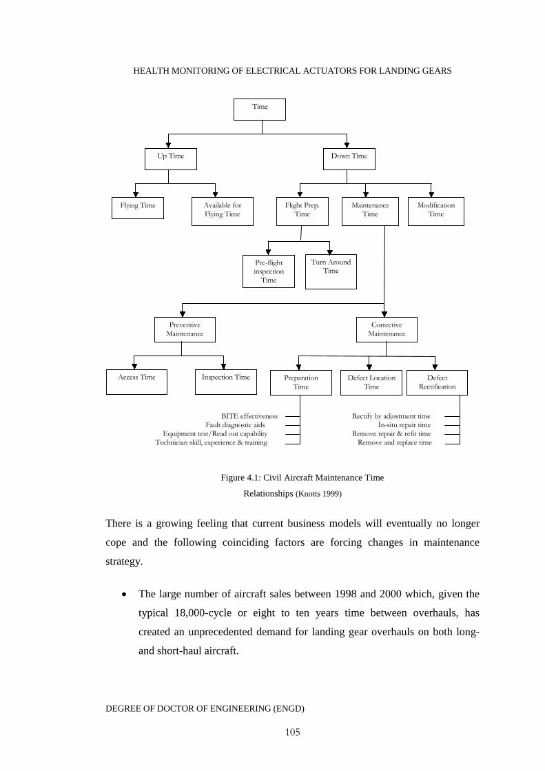
HEALTH MONITORING OF ELECTRICAL ACTUATORS FOR LANDING GEARS
DEGREE OF DOCTOR OF ENGINEERING (ENGD)
105
Figure 4.1: Civil Aircraft Maintenance Time
Relationships (Knotts 1999)
There is a growing feeling that current business models will eventually no longer
cope and the following coinciding factors are forcing changes in maintenance
strategy.
The large number of aircraft sales between 1998 and 2000 which, given the
typical 18,000-cycle or eight to ten years time between overhauls, has
created an unprecedented demand for landing gear overhauls on both long-
and short-haul aircraft.
Time
Up Time Down Time
Flying Time Available forFlying Time
Flight Prep.Time
MaintenanceTime
ModificationTime
Pre-flightinspection
Time
Turn AroundTime
PreventiveMaintenance
CorrectiveMaintenance
Access Time Inspection Time PreparationTime
Defect LocationTime
DefectRectification
Time
BITE effectivenessFault diagnostic aids
Equipment test/Read out capabilityTechnician skill, experience & training
Rectify by adjustment timeIn-situ repair time
Remove repair & refit timeRemove and replace time
HEALTH MONITORING OF ELECTRICAL ACTUATORS FOR LANDING GEARS
DEGREE OF DOCTOR OF ENGINEERING (ENGD)
106
Record aircraft production following unprecedented sales in 2006 and 2007.
Higher utilization of short-haul aircraft, which has shortened time between
overhauls for some airlines by one or more years.
The growing number of aircraft in service, including some older types
returned from desert storage, bringing more and more landing gear into the
market. This also has increased the number leakage or heavy corrosion
findings in line maintenance which also drives early overhauls.
A lack of landing gear overhauls capacity created by the high cost of setting
up an overhaul facility. The number of service providers has not grown
enough to meet the increasing demand.
Seasonal cycles have overloaded winter overhaul slots, leaving some
summer slots unfilled.
A worldwide shortage of raw materials like rubber, high strength steel and
titanium, exacerbated by increasing demand from the burgeoning economies
of China and India.
The on-going conflicts in Iraq and Afghanistan, which make significant
demands on spare-part production and material supply.
Complacent operators who either ignored the "need-to-plan" warnings from
the OEMs or simply have left landing gear overhauls to the last minute
4.3 Changing Maintenance Practice
Currently the European market holds a 26% share of the worldwide MRO business
compared to 39% held by North America and is expected to experience further

HEALTH MONITORING OF ELECTRICAL ACTUATORS FOR LANDING GEARS
DEGREE OF DOCTOR OF ENGINEERING (ENGD)
107
dramatic worldwide growth during the next 10 years (Jenson 2008). There are
however several hurdles which must be overcome by these MRO providers in order to
continue their leading global market shares (Fitzsimons 2007). Examples of which
include:
Growing competition from the Middle East.
Greater competition from original equipment manufacturers.
Continuing pressure from airlines to reduce costs.
These hurdles coupled with increased demand for airline MRO are forcing changes in
the global aviation maintenance industries, including:
MRO providers are expanding their geographical reach and capabilities in a
bid to become regional and global full service providers.
Spending on MRO is expected to universally increase.
Airlines are now seeking how to make the next level of savings, which has
raise the demand for more predictive maintenance strategies, with more
reliability and material solutions to compliment outsourced maintenance repair
work.
To drive further cost reductions, airlines are seeking to incorporate
sophisticated maintenance management solutions into their aircraft, reducing
investments in inventory and to aid in improvements in airline operations and
reliability.
Such factors have begun to dictate a change in maintenance strategy for operators and
the solutions in the services that the MRO suppliers can provide. These will aid in
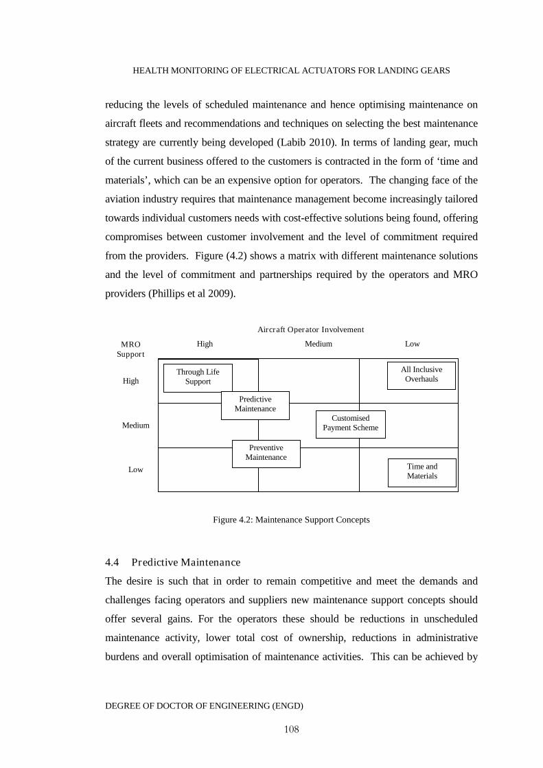
HEALTH MONITORING OF ELECTRICAL ACTUATORS FOR LANDING GEARS
DEGREE OF DOCTOR OF ENGINEERING (ENGD)
108
reducing the levels of scheduled maintenance and hence optimising maintenance on
aircraft fleets and recommendations and techniques on selecting the best maintenance
strategy are currently being developed (Labib 2010). In terms of landing gear, much
of the current business offered to the customers is contracted in the form of ‘time and
materials’, which can be an expensive option for operators. The changing face of the
aviation industry requires that maintenance management become increasingly tailored
towards individual customers needs with cost-effective solutions being found, offering
compromises between customer involvement and the level of commitment required
from the providers. Figure (4.2) shows a matrix with different maintenance solutions
and the level of commitment and partnerships required by the operators and MRO
providers (Phillips et al 2009).
Figure 4.2: Maintenance Support Concepts
4.4 Predictive Maintenance
The desire is such that in order to remain competitive and meet the demands and
challenges facing operators and suppliers new maintenance support concepts should
offer several gains. For the operators these should be reductions in unscheduled
maintenance activity, lower total cost of ownership, reductions in administrative
burdens and overall optimisation of maintenance activities. This can be achieved by
Through LifeSupport
High Medium Low
Aircraft Operator Involvement
MROSupport
PredictiveMaintenance
PreventiveMaintenance
CustomisedPayment Scheme
Time andMaterials
All InclusiveOverhaulsHigh
Medium
Low
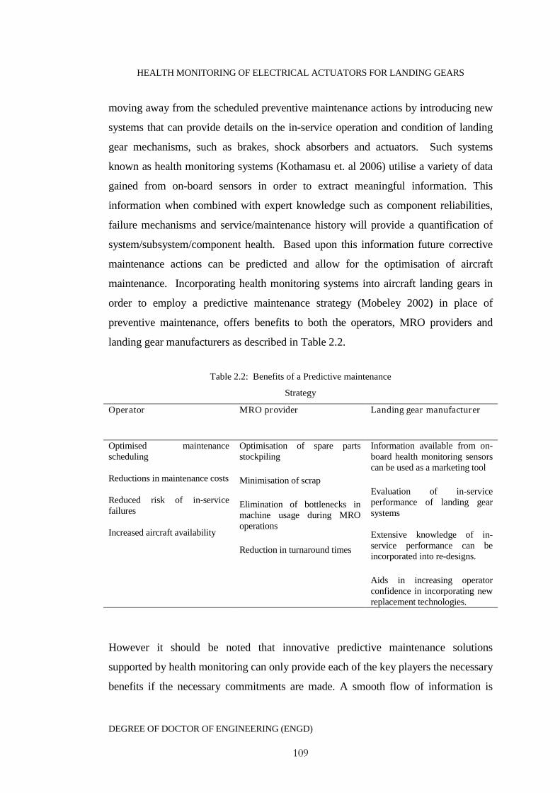
HEALTH MONITORING OF ELECTRICAL ACTUATORS FOR LANDING GEARS
DEGREE OF DOCTOR OF ENGINEERING (ENGD)
109
moving away from the scheduled preventive maintenance actions by introducing new
systems that can provide details on the in-service operation and condition of landing
gear mechanisms, such as brakes, shock absorbers and actuators. Such systems
known as health monitoring systems (Kothamasu et. al 2006) utilise a variety of data
gained from on-board sensors in order to extract meaningful information. This
information when combined with expert knowledge such as component reliabilities,
failure mechanisms and service/maintenance history will provide a quantification of
system/subsystem/component health. Based upon this information future corrective
maintenance actions can be predicted and allow for the optimisation of aircraft
maintenance. Incorporating health monitoring systems into aircraft landing gears in
order to employ a predictive maintenance strategy (Mobeley 2002) in place of
preventive maintenance, offers benefits to both the operators, MRO providers and
landing gear manufacturers as described in Table 2.2.
Table 2.2: Benefits of a Predictive maintenance
Strategy
Operator MRO provider Landing gear manufacturer
Optimised maintenancescheduling
Reductions in maintenance costs
Reduced risk of in-servicefailures
Increased aircraft availability
Optimisation of spare partsstockpiling
Minimisation of scrap
Elimination of bottlenecks inmachine usage during MROoperations
Reduction in turnaround times
Information available from on-board health monitoring sensorscan be used as a marketing tool
Evaluation of in-serviceperformance of landing gearsystems
Extensive knowledge of in-service performance can beincorporated into re-designs.
Aids in increasing operatorconfidence in incorporating newreplacement technologies.
However it should be noted that innovative predictive maintenance solutions
supported by health monitoring can only provide each of the key players the necessary
benefits if the necessary commitments are made. A smooth flow of information is
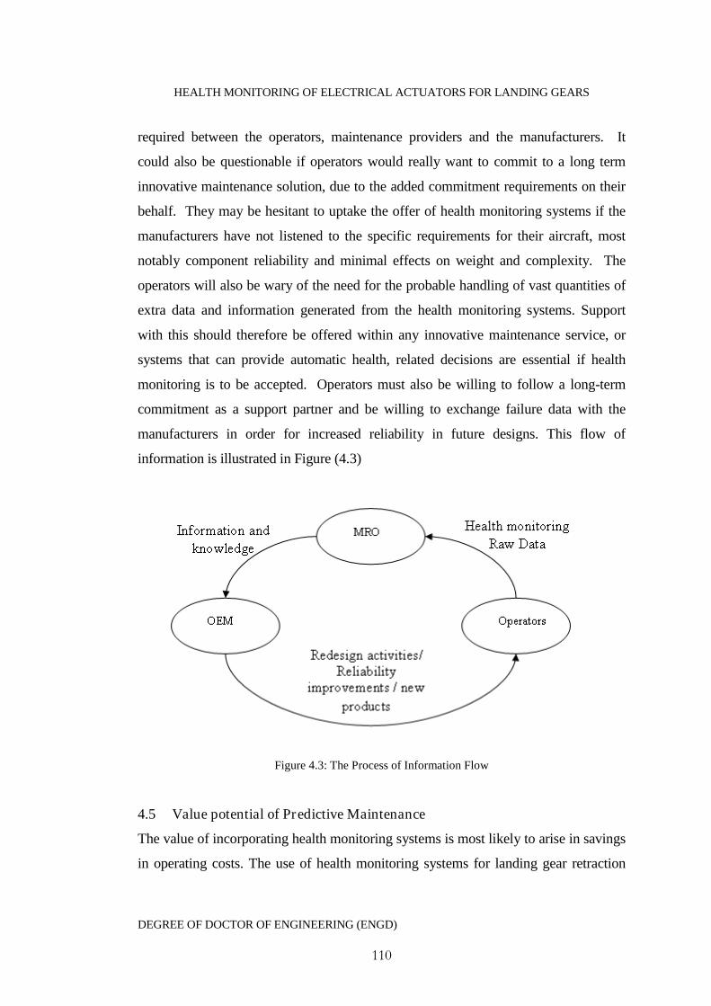
HEALTH MONITORING OF ELECTRICAL ACTUATORS FOR LANDING GEARS
DEGREE OF DOCTOR OF ENGINEERING (ENGD)
110
required between the operators, maintenance providers and the manufacturers. It
could also be questionable if operators would really want to commit to a long term
innovative maintenance solution, due to the added commitment requirements on their
behalf. They may be hesitant to uptake the offer of health monitoring systems if the
manufacturers have not listened to the specific requirements for their aircraft, most
notably component reliability and minimal effects on weight and complexity. The
operators will also be wary of the need for the probable handling of vast quantities of
extra data and information generated from the health monitoring systems. Support
with this should therefore be offered within any innovative maintenance service, or
systems that can provide automatic health, related decisions are essential if health
monitoring is to be accepted. Operators must also be willing to follow a long-term
commitment as a support partner and be willing to exchange failure data with the
manufacturers in order for increased reliability in future designs. This flow of
information is illustrated in Figure (4.3)
Figure 4.3: The Process of Information Flow
4.5 Value potential of Predictive Maintenance
The value of incorporating health monitoring systems is most likely to arise in savings
in operating costs. The use of health monitoring systems for landing gear retraction

HEALTH MONITORING OF ELECTRICAL ACTUATORS FOR LANDING GEARS
DEGREE OF DOCTOR OF ENGINEERING (ENGD)
111
mechanisms, or other aircraft systems, will offer a very competitive advantage in
maintenance decision-making, which is crucial for both military and commercial
aerospace users. This will help manufacturers retain customers and attract new
business; these aspects will mean that health monitoring solutions will become a key
part of formulating future maintenance strategies. The airline industry has seen a
rapid increase in operators over the past decade, particularly in low cost short haul
operators. The nature of the budget airlines business succeeds in the ability to operate
large aircraft fleets, coupled with high aircraft availability and short turn-around times
whilst keeping ticket costs low. For such factors to remain and for airlines to create a
business winning advantage, then strategic maintenance management has to become
one of the significant factors in their operations management. The adoption of health
monitoring and overall predictive maintenance can help push an aircraft operators
business forward as illustrated in Figure (4.4).
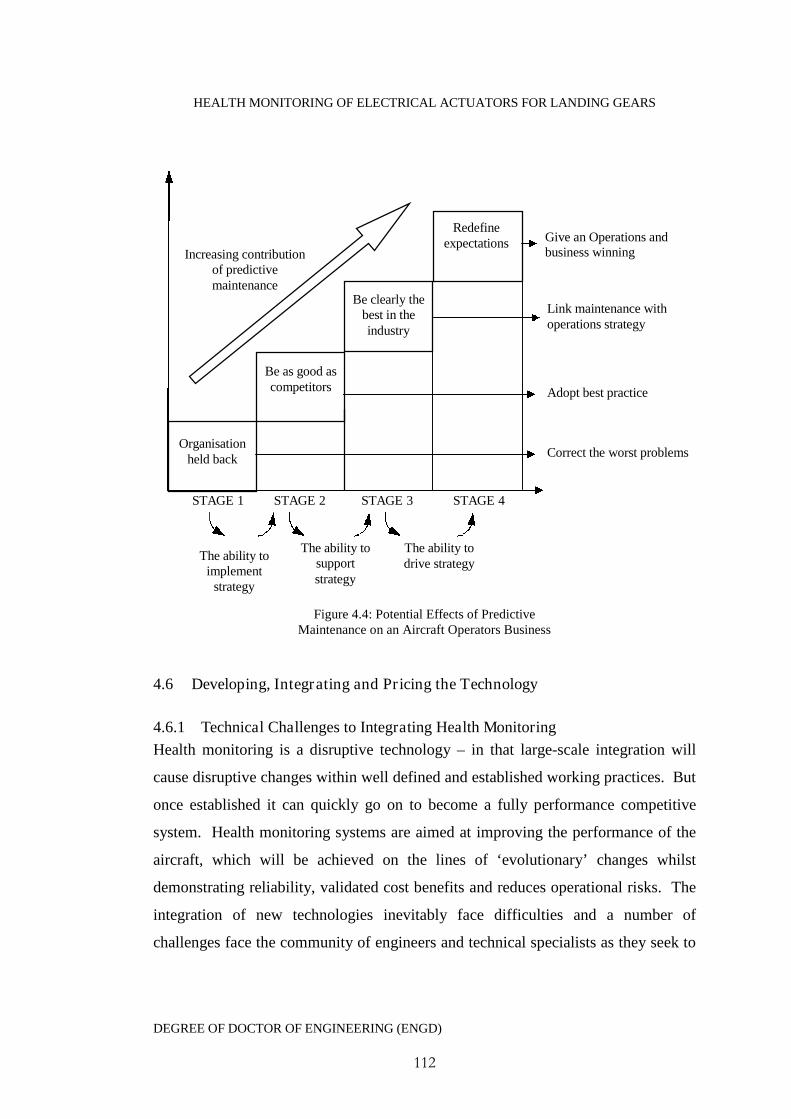
HEALTH MONITORING OF ELECTRICAL ACTUATORS FOR LANDING GEARS
DEGREE OF DOCTOR OF ENGINEERING (ENGD)
112
Figure 4.4: Potential Effects of PredictiveMaintenance on an Aircraft Operators Business
4.6 Developing, Integrating and Pricing the Technology
4.6.1 Technical Challenges to Integrating Health Monitoring
Health monitoring is a disruptive technology – in that large-scale integration will
cause disruptive changes within well defined and established working practices. But
once established it can quickly go on to become a fully performance competitive
system. Health monitoring systems are aimed at improving the performance of the
aircraft, which will be achieved on the lines of ‘evolutionary’ changes whilst
demonstrating reliability, validated cost benefits and reduces operational risks. The
integration of new technologies inevitably face difficulties and a number of
challenges face the community of engineers and technical specialists as they seek to
Give an Operations andbusiness winningAdvantage
Link maintenance withoperations strategy
Adopt best practice
Correct the worst problems
STAGE 1 STAGE 2 STAGE 3 STAGE 4
Organisationheld back
Be as good ascompetitors
Be clearly thebest in theindustry
Redefineexpectations
The ability toimplement
strategy
The ability tosupportstrategy
The ability todrive strategy
Increasing contributionof predictivemaintenance
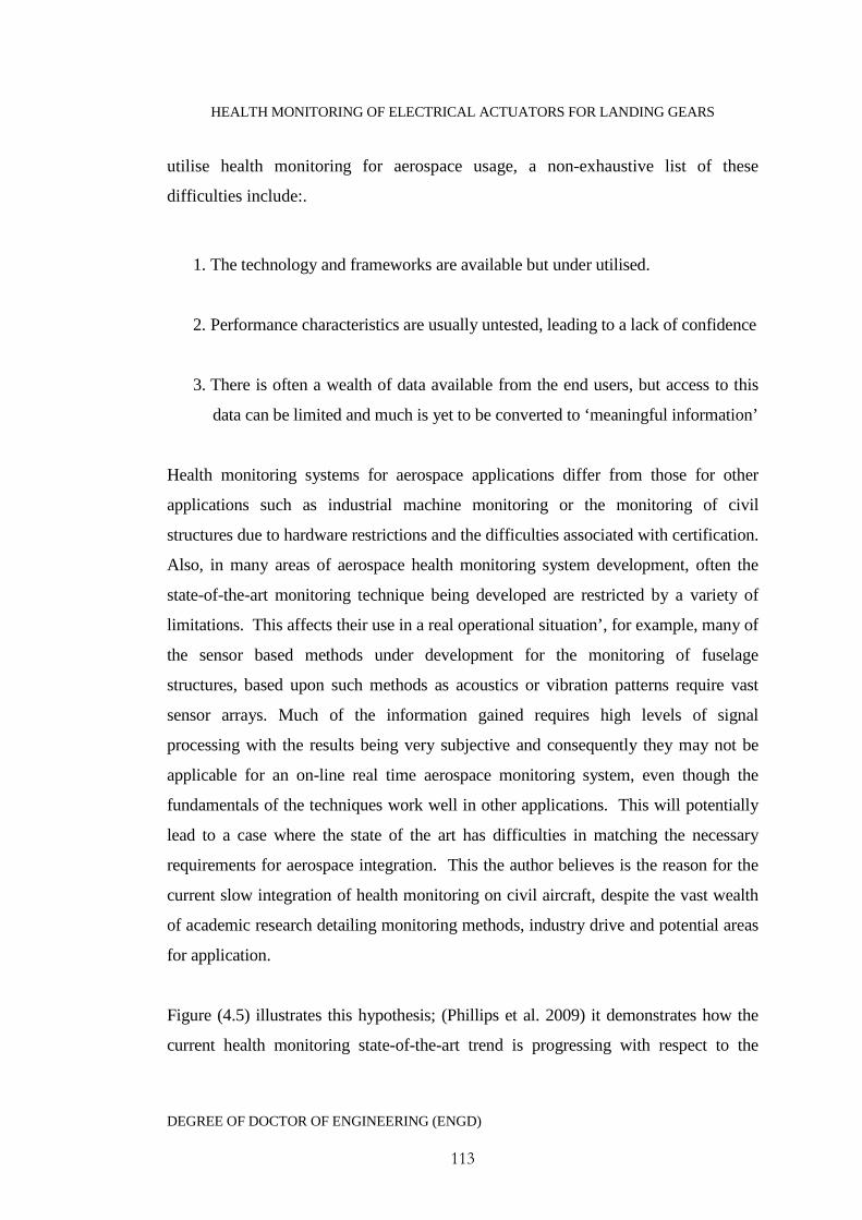
HEALTH MONITORING OF ELECTRICAL ACTUATORS FOR LANDING GEARS
DEGREE OF DOCTOR OF ENGINEERING (ENGD)
113
utilise health monitoring for aerospace usage, a non-exhaustive list of these
difficulties include:.
1. The technology and frameworks are available but under utilised.
2. Performance characteristics are usually untested, leading to a lack of confidence
3. There is often a wealth of data available from the end users, but access to this
data can be limited and much is yet to be converted to ‘meaningful information’
Health monitoring systems for aerospace applications differ from those for other
applications such as industrial machine monitoring or the monitoring of civil
structures due to hardware restrictions and the difficulties associated with certification.
Also, in many areas of aerospace health monitoring system development, often the
state-of-the-art monitoring technique being developed are restricted by a variety of
limitations. This affects their use in a real operational situation’, for example, many of
the sensor based methods under development for the monitoring of fuselage
structures, based upon such methods as acoustics or vibration patterns require vast
sensor arrays. Much of the information gained requires high levels of signal
processing with the results being very subjective and consequently they may not be
applicable for an on-line real time aerospace monitoring system, even though the
fundamentals of the techniques work well in other applications. This will potentially
lead to a case where the state of the art has difficulties in matching the necessary
requirements for aerospace integration. This the author believes is the reason for the
current slow integration of health monitoring on civil aircraft, despite the vast wealth
of academic research detailing monitoring methods, industry drive and potential areas
for application.
Figure (4.5) illustrates this hypothesis; (Phillips et al. 2009) it demonstrates how the
current health monitoring state-of-the-art trend is progressing with respect to the
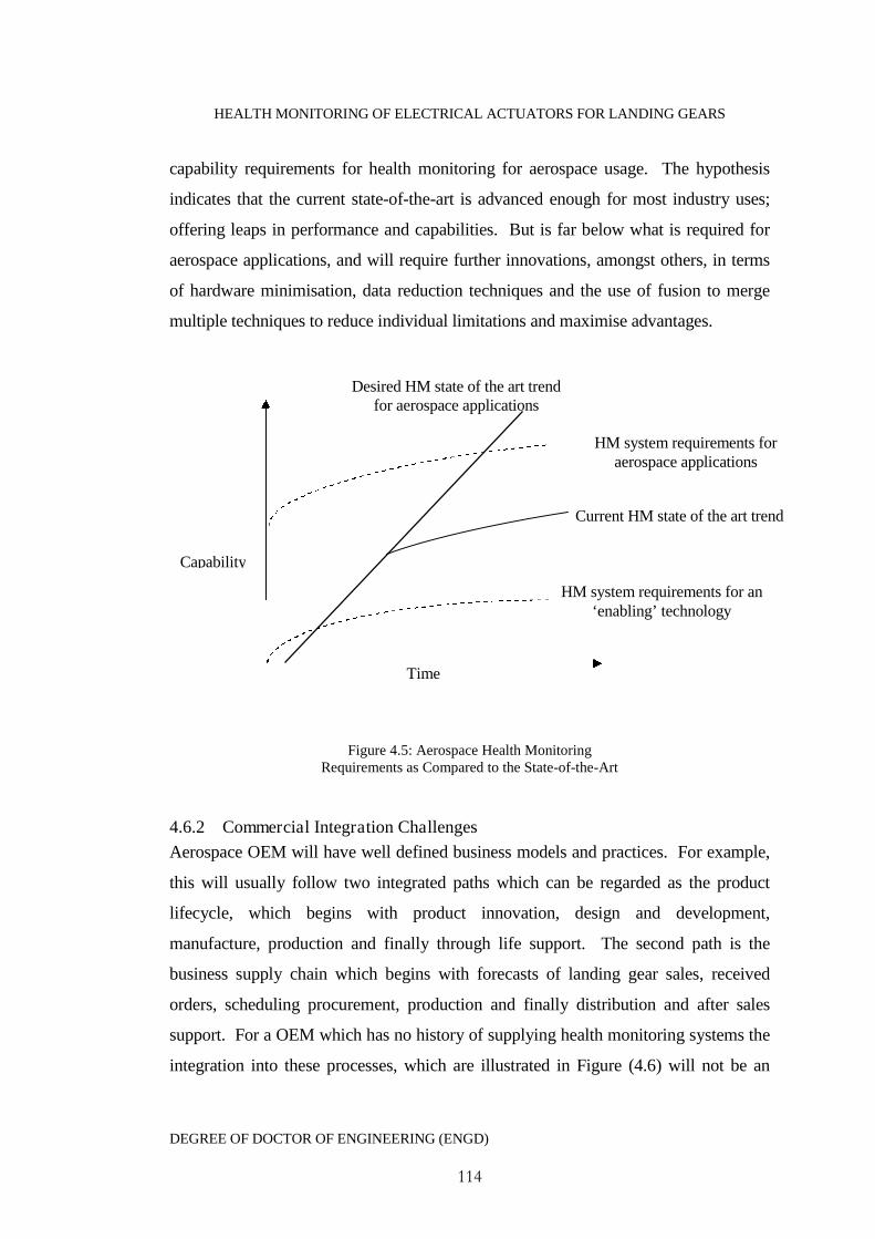
HEALTH MONITORING OF ELECTRICAL ACTUATORS FOR LANDING GEARS
DEGREE OF DOCTOR OF ENGINEERING (ENGD)
114
capability requirements for health monitoring for aerospace usage. The hypothesis
indicates that the current state-of-the-art is advanced enough for most industry uses;
offering leaps in performance and capabilities. But is far below what is required for
aerospace applications, and will require further innovations, amongst others, in terms
of hardware minimisation, data reduction techniques and the use of fusion to merge
multiple techniques to reduce individual limitations and maximise advantages.
Figure 4.5: Aerospace Health MonitoringRequirements as Compared to the State-of-the-Art
4.6.2 Commercial Integration Challenges
Aerospace OEM will have well defined business models and practices. For example,
this will usually follow two integrated paths which can be regarded as the product
lifecycle, which begins with product innovation, design and development,
manufacture, production and finally through life support. The second path is the
business supply chain which begins with forecasts of landing gear sales, received
orders, scheduling procurement, production and finally distribution and after sales
support. For a OEM which has no history of supplying health monitoring systems the
integration into these processes, which are illustrated in Figure (4.6) will not be an
Time
HM system requirements for an‘enabling’ technology
HM system requirements foraerospace applications
Current HM state of the art trend
Capability
Desired HM state of the art trendfor aerospace applications
HEALTH MONITORING OF ELECTRICAL ACTUATORS FOR LANDING GEARS
DEGREE OF DOCTOR OF ENGINEERING (ENGD)
115
easy task. Integration of health monitoring for instance will directly affect how after
sales service and through life support is conducted. For successful commercial
integration it is very probable that a whole new structure to the suppliers’ business
model will be required.
Figure 4.6: Logistics Chain and Business Management
Some of the more general issues (Raheja et al. 2006) relate to the conceptualisation of
strategies for decision making and goal setting across multiple 'component or system'
levels and time periods. A unique business methodology for incorporating cost as a
factor to be considered in setting up these decision making strategies is a fundamental
requirement for the successful integration of health monitoring technologies. Other
considerations involve the linking of the maintenance system with Enterprise and
Materials Resource Planning (ERP/MRP) to enable optimisation of spare parts
ordering, and therefore ensuring the after sales and through life support elements of
the business remain at their optimal capabilities.
Salesforecasts
Orders Schedulingprocurement
Distributionand after sales
service
Productinnovation
Designand
development
Manufacture
Production
Throughlife
support
Demand forHM
Integration
Logistics chain /Businessmanagement
Product / ProcessLifecycle

HEALTH MONITORING OF ELECTRICAL ACTUATORS FOR LANDING GEARS
DEGREE OF DOCTOR OF ENGINEERING (ENGD)
116
4.6.3 Pricing Deployment Strategies
There are very few published works which detail proposed pricing models for health
monitoring technology. The reasons for this are generally due to the secretive nature
of organisations have over their business models, one example however with direct
relevance to this current work is provided by Kidd 2006. This Engineering Doctorate
thesis provides an extensive discussion on business and pricing models for health
monitoring for automotive vehicles as seen from the vehicle OEM perspective. The
nature of the automotive and aerospace commercial business operate on very different
principles, but the models in this work provide a framework in developing pricing
models for aerospace actuator health monitoring solutions.
A number of pricing models are therefore proposed in order to generate revenue for
the provider of the health monitoring system, which is aimed at adding significant
added value to their landing gear products. As has been identified there are several key
players in aircraft maintenance, which all must be included in any deployment/pricing
models, if health monitoring on landing gears are to be successful. It is logical that
any integration of health monitoring hardware as a standard addition to landing gears
are technically sold to the aircraft OEM directly. However, as any additional costs
met by the aircraft OEM, will almost certainly be met by the aircraft purchasers
(operators), and because it is the operator’s responsibility for maintaining their aircraft
the health monitoring customer is simplified to be the aircraft operators in this case.
1. The first pricing model generates revenue based upon sales volumes (variable
costs).A unit cost is paid by the landing gear customer to the health monitoring
system provider for every landing gear set using the monitoring technology.
2. A second pricing model is based upon per landing gear unit (fixed cost). A
one off payment is made to the health monitoring provider for any given
monitoring solution per landing gear set. This ensures that the customer
retains the ownership for the life of that product.
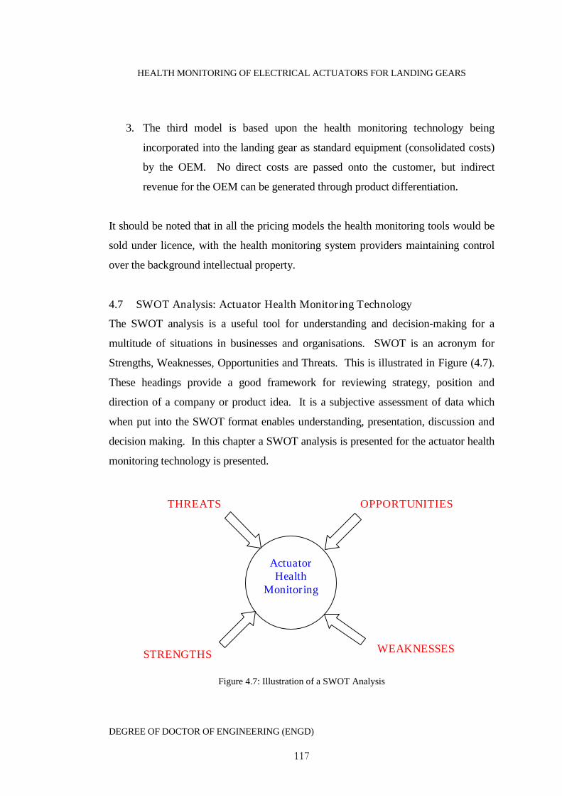
HEALTH MONITORING OF ELECTRICAL ACTUATORS FOR LANDING GEARS
DEGREE OF DOCTOR OF ENGINEERING (ENGD)
117
3. The third model is based upon the health monitoring technology being
incorporated into the landing gear as standard equipment (consolidated costs)
by the OEM. No direct costs are passed onto the customer, but indirect
revenue for the OEM can be generated through product differentiation.
It should be noted that in all the pricing models the health monitoring tools would be
sold under licence, with the health monitoring system providers maintaining control
over the background intellectual property.
4.7 SWOT Analysis: Actuator Health Monitoring Technology
The SWOT analysis is a useful tool for understanding and decision-making for a
multitude of situations in businesses and organisations. SWOT is an acronym for
Strengths, Weaknesses, Opportunities and Threats. This is illustrated in Figure (4.7).
These headings provide a good framework for reviewing strategy, position and
direction of a company or product idea. It is a subjective assessment of data which
when put into the SWOT format enables understanding, presentation, discussion and
decision making. In this chapter a SWOT analysis is presented for the actuator health
monitoring technology is presented.
Figure 4.7: Illustration of a SWOT Analysis
ActuatorHealth
Monitoring
THREATS
STRENGTHS
OPPORTUNITIES
WEAKNESSES

HEALTH MONITORING OF ELECTRICAL ACTUATORS FOR LANDING GEARS
DEGREE OF DOCTOR OF ENGINEERING (ENGD)
118
It should be noted that other market analysis tools exist. For example one could have
used a PEST analysis. PEST, an acronym for Political, Environmental, Social and
Technological is a useful tool for understanding market growth or decline. As a PEST
analysis most commonly measures an existing market, whilst a SWOT analysis is
used to measure a proposition or business idea, the SWOT analysis was chosen to be
used to assess commercial applicability of actuator health monitoring.
4.7.1 Strengths
Aerospace OEM, MRO providers and aircraft operators have expressed
interests in aerospace health monitoring technologies.
There are a number of advantages offered to OEM, MRO providers and
aircraft operators.
Combining information generated from the actuator health monitoring system
with other aerospace monitoring systems as part of a Integrated vehicle Health
Monitoring (IVHM) system will increase overall aircraft safety, reliability and
operational lifespan
Actuator health monitoring will aid in increasing customer confidence in new
replacement all electric actuator technology.
OEM can make extensive use of in-service performance data generated from
the monitoring system for re-design improvements.
Electromechanical actuators used in different applications all share the same
common component types and general operating procedure. This means that
an actuator monitoring system could be packaged and sold off-the-shelf. With
customers only required to perform simple tuning for their individual
application.

HEALTH MONITORING OF ELECTRICAL ACTUATORS FOR LANDING GEARS
DEGREE OF DOCTOR OF ENGINEERING (ENGD)
119
4.7.2 Weaknesses
Aerospace certification procedures for new hardware/software coupled with
the requirements for aircraft weight reduction may restrict the addition of a
health monitoring systems.
There may be a reluctance to accept the monitoring technology by operators as
a new decision-making tool until the system has proven itself as an in-service
reliable technology.
In general the incorporation of health monitoring would allow serviceable
components to remain in service for longer periods. This may result in OEM’s
and third party providers loosing revenue generated by periodic maintenance.
Once health monitoring systems are in place they must be reliable. Unreliable
monitoring will result in reductions in customer confidence. This would lead
to reluctance for future customers to invest in the technology.
4.7.3 Opportunities
Environmental factors have led to new governmental legislation demanding
cleaner and more fuel efficient aircraft. This has led designers and
manufacturers to begin incorporating innovative replacement technologies, for
example, the new all electric actuation. If these are accepted then a market for
health monitoring systems will open up to support their reliability and gain
customer confidence in replacement technologies.
Electromechanical actuation is not just confined to aerospace applications. The
rail, automotive, shipping and power processing industries all make use of
them. More often than not in mission or safety critical applications. This
offers the potential for a cross-market business.

HEALTH MONITORING OF ELECTRICAL ACTUATORS FOR LANDING GEARS
DEGREE OF DOCTOR OF ENGINEERING (ENGD)
120
Health monitoring offers the potential to improve current maintenance
operations. Allowing the provider to supply the customers with a range of
innovative maintenance packages. These could be tailored to individual
customer requirements, offering a competitive business winning advantage
over competitors.
4.7.4 Threats
Customers may see the introduction of health monitoring to enhance product
reliability as an admittance of inherent product unreliability.
There are currently several key European aerospace companies investigating
the potential use of electromechanical actuation for landing gears. It is highly
unlikely that these are oblivious to the potential advantages posed by health
monitoring. There is also a more advanced drive for similar actuators for other
aerospace applications such as control surfaces. There is a risk therefore that a
competitor could be the first to the market.
It is difficult to evaluate the cost of manufacture, implementation and upkeep
of a health monitoring system in development. It may be the case that aircraft
operators will not see health monitoring as an economically viable option they
may therefore seek other maintenance solutions.
Aerospace certification procedures may lead to the technologies which health
monitoring is aimed at supporting not being accepted for incorporation into
aircraft. This would make the designed monitoring system instantly
redundant.
Landing gear actuator health monitoring is just one monitoring system that is
likely to see introduction onto aircraft in the future. For all of these systems to
HEALTH MONITORING OF ELECTRICAL ACTUATORS FOR LANDING GEARS
DEGREE OF DOCTOR OF ENGINEERING (ENGD)
121
be optimally effective it would be desirable for them to work together.
However this will be unlikely the case due to each supplier using incompatible
hardware and software. This would make the case for a fully IVHM system
unlikely, with operators choosing to optimise their selection of monitoring
systems, leaving some key items on the aircraft as unmonitored. Landing gear
actuation may be one of these items.
4.8 Conclusion
Health monitoring technology is intractably tied up with aerospace maintenance
activities as a whole. The aerospace maintenance industry is currently facing a time of
unprecedented demand for spare parts, complete overhauls and general servicing.
This is due to, amongst other reasons, a sudden increase in aircraft numbers in the last
decade or so which now have key systems such as landing gears reaching the end of
their life. This is therefore putting a strain on overhaul providers and Original
Equipment Manufacturers (OEM). This has begun to force operators, OEM and
overhaul providers to begin seeking new innovative maintenance solutions, to meet
rising demands and costs. The nature of this therefore opens up the possibility of
integrating health monitoring technologies into OEM business models.
It is envisioned as part of this thesis work that health monitoring technology will play
a crucial role in revolutionising aircraft maintenance practice. This it will be proposed
will not come about entirely as a direct result of the implementation of the technology.
But rather by a set of unique customised solutions and support packages offered as a
result of mature health monitoring technology. It has long been the tradition that
operators are secretive when it comes to information regarding the maintenance of
their fleets, information that suppliers often have to purchase in order to optimise their
spare parts inventories. It is also proposed that for customised maintenance support
packages to be successful, there must be a beneficial trade off for all players involved,
and this will require changes to the way the key players share information.

HEALTH MONITORING OF ELECTRICAL ACTUATORS FOR LANDING GEARS
DEGREE OF DOCTOR OF ENGINEERING (ENGD)
122
4.9 References
Fitzsimons., B. (2007), 'The BIG picture: Airline MRO in a global context'. Airline
Fleet & Network Management, Vol 52, pp. 46-54.
Gramopadyhe, A.., Drury, C. (2000), 'Human factors in aviation maintenance: How
we got to where we are', International Journal of Industrial Ergonomics, Vol 26, pp.
125-131.
Jenson, D. (2008), 'Europe’s Challenges In a Dynamic MRO Market'. [cited 4th April
2009]; Available from: http://www.aviationtoday.com/.
Kidd, M., (2006), 'Automotive condition monitoring using standard vehicle
Architecture', Engineering Doctorate Thesis, University of Manchester, UK
Kothamasu, R., Huang, S., VerDuin, W. (2006), 'System health monitoring and
prognostics - a review of current paradigms and practices', in International Journal of
Advanced Manufacturing Technology. Springer-Verlag. pp. 1012-24.
Knotts., R.M., (1999), 'Civil aircraft maintenance and support fault diagnosis from a
bussiness perspective', Journal of Quality in Maintenance Engineering, Vol 5, No 4,
pp. 335-348.
Labib, A., (2010), 'Maintenance strategies: A systematic approach for selection of the
right strategies', Proceedings of the 4th World Congress on Engineering Asset
Management, Athens, Greece
Mobley, R. (2002). 'An introduction to predictive maintenance,' Materials &
Mechanical. Elsevier Butterworth-Heinemann.

HEALTH MONITORING OF ELECTRICAL ACTUATORS FOR LANDING GEARS
DEGREE OF DOCTOR OF ENGINEERING (ENGD)
123
Patkai, B., Theodorou, L., McFarlane, D,. Schmidt, K. (2007), 'Requirements for
RFID-based Sensor Integration in Landing Gear Monitoring - A Case Study', Auto-ID
Lab, University of Cambridge.
P. Phillips, D. Diston, A. Starr, J. Payne and S. Pandya, (2009), ‘A review on the
optimisation of aircraft maintenance with application to landing gears’, World
Congress in Engineering Asset Management, Athens, Greece
Raheja, D., llinas, J., Romanowski, C. (2006), 'Data fusion/data mining-based
architecture for condition-based maintenance', International Journal of Production
Research, Vol. 44, no. 14, pp. 2869-2887

HEALTH MONITORING OF ELECTRICAL ACTUATORS FOR LANDING GEARS
DEGREE OF DOCTOR OF ENGINEERING (ENGD)
124
C h a p t e r 5 : H e a l t h M o n i t o r i n g S y s t e m sM e t h o d o l o g y a n d F r a m e w o r k
5.1 Introduction
Before undertaking the design of any health monitoring system, a study on what is
required and by what process it can be or will be achieved is required. This does not
simply mean attempting to force the system to be monitored into a popular health
monitoring technique or into off the shelf monitoring systems. Rather an approach is
required that takes into consideration all of the necessary information regarding the
specific system to be monitored (i.e. failure history, design requirements, costs,
quality of information), utilising this information to develop and integrate application
specific health monitoring. In order to achieve this then an appropriate framework is
required which provides a set of generic guidelines for the development of the health
monitoring system.
The purpose of this chapter is to provide such a framework based upon the concept of
data fusion for the design of the actuator health monitoring system. The purpose of
which is not to provide a detailed specification of the hardware or software, but rather
to provide a conceptual description of the modules that will aid in the systems
development. Descriptions are enhanced through the use of relevant examples
throughout this chapter. A discussion is also provided on the engineering need for the
monitoring capability to satisfy verification criteria in the form of diagnostic
performance metrics and technical value.
5.2 Framework Objectives
The objectives of the framework presented as part of this research are defined as
follows (Phillips et al. 2008):
Provide a generic framework for electromechanical health monitoring which
will demonstrate how qualitative, quantitative and heuristic information can
be used together to achieve maintenance objectives.

HEALTH MONITORING OF ELECTRICAL ACTUATORS FOR LANDING GEARS
DEGREE OF DOCTOR OF ENGINEERING (ENGD)
125
Illustrate the importance and applicability of using data fusion for health
monitoring in this application.
To show the application and benefits of utilising data fusion alongside
conventional health monitoring techniques, methodologies and standards.
To provide a methodology for the conversion of high-level organisational
maintenance objectives into objectives pertaining to the specific actuator
system and subsystem components. These can then be used to aid in:
- Developing component descriptions, such as ‘part trees’
- Identifying failure modes for the relevant components in the form of
‘fault trees’.
To provide and understand the interrelationships of the various
architectural modules, which contain the functions and processes that
interrelate to accomplish the overall system goals.
Provide a generic framework and module descriptors, which are
applicable to a wide range of health monitoring techniques and allow the
architecture to be accessible for additional sensor data, information
extraction and decision making tools.
5.3 Overview of the Health Monitoring Data Fusion Framework
Based upon reviews of data fusion models, health monitoring standards, requirements
and standards a top level architecture has been chosen for the current application. In
order to maximise the information obtainable from multiple data sources then the data
must be used together effectively. Data obtained through on-board acquisition
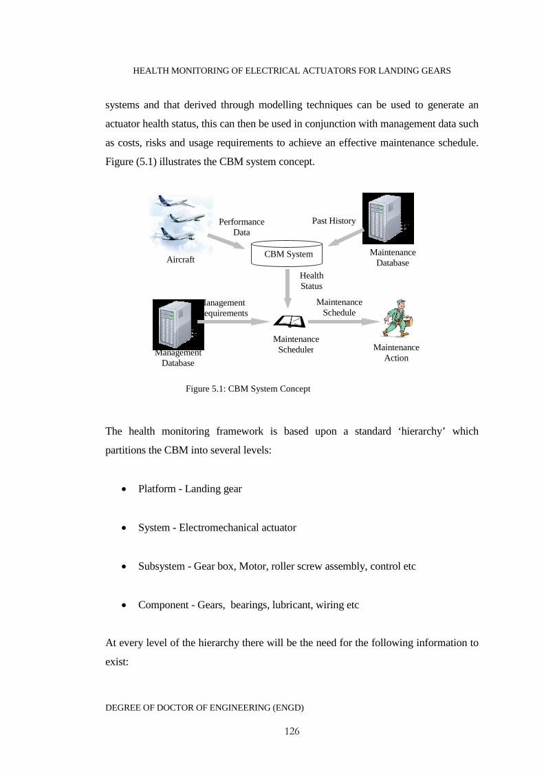
HEALTH MONITORING OF ELECTRICAL ACTUATORS FOR LANDING GEARS
DEGREE OF DOCTOR OF ENGINEERING (ENGD)
126
systems and that derived through modelling techniques can be used to generate an
actuator health status, this can then be used in conjunction with management data such
as costs, risks and usage requirements to achieve an effective maintenance schedule.
Figure (5.1) illustrates the CBM system concept.
Figure 5.1: CBM System Concept
The health monitoring framework is based upon a standard ‘hierarchy’ which
partitions the CBM into several levels:
Platform - Landing gear
System - Electromechanical actuator
Subsystem - Gear box, Motor, roller screw assembly, control etc
Component - Gears, bearings, lubricant, wiring etc
At every level of the hierarchy there will be the need for the following information to
exist:
HealthStatus
PerformanceData
Past History
ManagementRequirements
AircraftMaintenance
Database
MaintenanceSchedulerManagement
Database
CBM System
MaintenanceSchedule
MaintenanceAction

HEALTH MONITORING OF ELECTRICAL ACTUATORS FOR LANDING GEARS
DEGREE OF DOCTOR OF ENGINEERING (ENGD)
127
1. Component identification
2. Identified component failure modes
3. CBM objectives pertaining to each group of system/subsystem/component
levels
4. Health estimates relating to the state of the failure mode,
Figure (5.2) is an illustrated representation of the proposed architecture along with the
corresponding OSA-CBM framework modules lain out by Raheja et al. (2006). It
should be noted that it is likely that a combination of fusion levels will be required, as
described by the JDL data fusion framework, reviewed in Chapter 3.
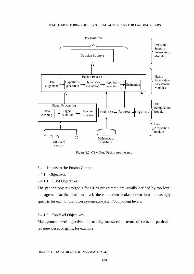
HEALTH MONITORING OF ELECTRICAL ACTUATORS FOR LANDING GEARS
DEGREE OF DOCTOR OF ENGINEERING (ENGD)
128
Figure 5.2: CBM Data Fusion Architecture
5.4 Inputs to the Fusion Centre
5.4.1 Objectives
5.4.1.1 CBM Objectives
The generic objectives/goals for CBM programme are usually defined by top level
management at the platform level; these are then broken down into increasingly
specific for each of the lower system/subsystem/component levels.
5.4.1.2 Top level Objectives
Management level objectives are usually measured in terms of costs, in particular
revenue losses or gains, for example:
Dataalignment
Hypothesisgeneration
Hypothesisselection
Hypothesisevaluation Estimation
Fusion Process
MaintenanceDatabase
ObjectivesPart treesFault trees
On-boardsensors
Signal Processing
Decision Support
Presentation
DataAcquisitionmodule
DataManipulationModule
DecisionSupport/PresentationModules
Datacleaning
Signalcondition
Featureextraction
HealthMonitoring/AssessmentModules

HEALTH MONITORING OF ELECTRICAL ACTUATORS FOR LANDING GEARS
DEGREE OF DOCTOR OF ENGINEERING (ENGD)
129
1. Reduce aircraft maintenance costs.
2. Maximise the number of aircraft flight hours.
3. Increase aircraft safety
5.4.1.3 Platform Level CBM Objectives
The platform level objectives, relate directly to the electromechanical actuators
mounted upon the landing gears. These objectives are normally associated with
reducing the probability of an event occurring. They relate to the failure of the entire
actuation system to perform its required function leading to a loss of the landing gears
normal operation such as the following:
1. Prevent the risk of the actuator from jamming leading to a failure to
retract/extend the landing gears, impacting upon aircraft safety.
2. Prevent inadvertent retraction/extension of the landing gears.
3. Prevent failure to damp the landing gears during extension/retraction, risking
increased structural damage.
5.4.1.4 Lower System/Component Level Objectives
Once the platform level objectives have been designed objectives for the lower
system, subsystem and component levels can be derived. These objectives will also
be based around improvements in the individual system and subsystems. For example
if an event such as actuator jamming is a result of a gear box failure, then the objective
at the system level may be to increase the Mean Times Between Failures (MTBF) of
the gear box. Likewise if the gear box failures are a result of the gears failing due to
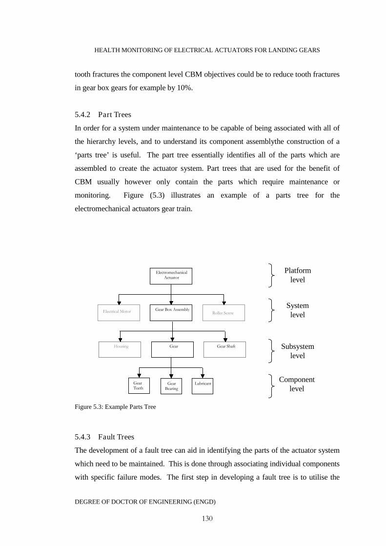
HEALTH MONITORING OF ELECTRICAL ACTUATORS FOR LANDING GEARS
DEGREE OF DOCTOR OF ENGINEERING (ENGD)
130
tooth fractures the component level CBM objectives could be to reduce tooth fractures
in gear box gears for example by 10%.
5.4.2 Part Trees
In order for a system under maintenance to be capable of being associated with all of
the hierarchy levels, and to understand its component assemblythe construction of a
‘parts tree’ is useful. The part tree essentially identifies all of the parts which are
assembled to create the actuator system. Part trees that are used for the benefit of
CBM usually however only contain the parts which require maintenance or
monitoring. Figure (5.3) illustrates an example of a parts tree for the
electromechanical actuators gear train.
Figure 5.3: Example Parts Tree
5.4.3 Fault Trees
The development of a fault tree can aid in identifying the parts of the actuator system
which need to be maintained. This is done through associating individual components
with specific failure modes. The first step in developing a fault tree is to utilise the
Gear Box Assembly
ElectromechanicalActuator
GearHousing Gear Shaft
GearTeeth
GearBearing
Lubricant
Electrical Motor Roller Screw
Platformlevel
Systemlevel
Subsystemlevel
Componentlevel
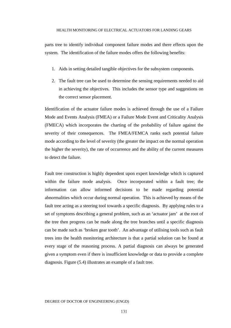
HEALTH MONITORING OF ELECTRICAL ACTUATORS FOR LANDING GEARS
DEGREE OF DOCTOR OF ENGINEERING (ENGD)
131
parts tree to identify individual component failure modes and there effects upon the
system. The identification of the failure modes offers the following benefits:
1. Aids in setting detailed tangible objectives for the subsystem components.
2. The fault tree can be used to determine the sensing requirements needed to aid
in achieving the objectives. This includes the sensor type and suggestions on
the correct sensor placement.
Identification of the actuator failure modes is achieved through the use of a Failure
Mode and Events Analysis (FMEA) or a Failure Mode Event and Criticality Analysis
(FMECA) which incorporates the charting of the probability of failure against the
severity of their consequences. The FMEA/FEMCA ranks each potential failure
mode according to the level of severity (the greater the impact on the normal operation
the higher the severity), the rate of occurrence and the ability of the current measures
to detect the failure.
Fault tree construction is highly dependent upon expert knowledge which is captured
within the failure mode analysis. Once incorporated within a fault tree; the
information can allow informed decisions to be made regarding potential
abnormalities which occur during normal operation. This is achieved by means of the
fault tree acting as a steering tool towards a specific diagnosis. By applying rules to a
set of symptoms describing a general problem, such as an ‘actuator jam’ at the root of
the tree then progress can be made along the tree branches until a specific diagnosis
can be made such as ‘broken gear tooth’. An advantage of utilising tools such as fault
trees into the health monitoring architecture is that a partial solution can be found at
every stage of the reasoning process. A partial diagnosis can always be generated
given a symptom even if there is insufficient knowledge or data to provide a complete
diagnosis. Figure (5.4) illustrates an example of a fault tree.
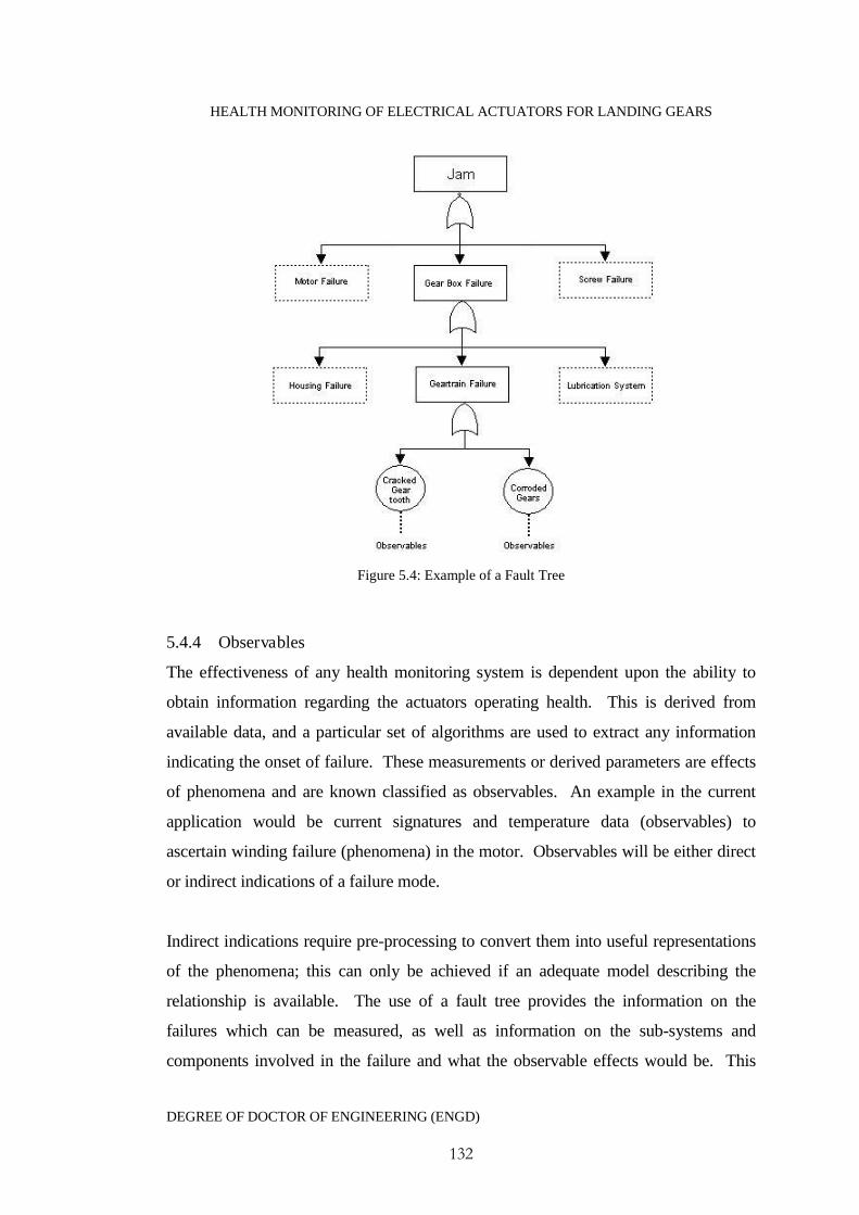
HEALTH MONITORING OF ELECTRICAL ACTUATORS FOR LANDING GEARS
DEGREE OF DOCTOR OF ENGINEERING (ENGD)
132
Figure 5.4: Example of a Fault Tree
5.4.4 Observables
The effectiveness of any health monitoring system is dependent upon the ability to
obtain information regarding the actuators operating health. This is derived from
available data, and a particular set of algorithms are used to extract any information
indicating the onset of failure. These measurements or derived parameters are effects
of phenomena and are known classified as observables. An example in the current
application would be current signatures and temperature data (observables) to
ascertain winding failure (phenomena) in the motor. Observables will be either direct
or indirect indications of a failure mode.
Indirect indications require pre-processing to convert them into useful representations
of the phenomena; this can only be achieved if an adequate model describing the
relationship is available. The use of a fault tree provides the information on the
failures which can be measured, as well as information on the sub-systems and
components involved in the failure and what the observable effects would be. This
HEALTH MONITORING OF ELECTRICAL ACTUATORS FOR LANDING GEARS
DEGREE OF DOCTOR OF ENGINEERING (ENGD)
133
allows partitioning of the observables as direct or indirect and aids in the choice of the
most appropriate observables, depending on the criticality of the failure mode, in
which to measure and hence the choice of sensor and sensor location. Table 5.1 shows
common sensor measurements which can be used as either ‘direct’ or ‘indirect’
estimates of selected EMA failures
Table 5.1: EMA Faults and Associated Observables
Damagedgears
Bearingdamage
Electricalmotor faults
Roller-screwstructuraldamage
Inadequate/poorlubrication
Excessiveloading
Corrosion
Vibrationanalysis • • • •
Thermalmonitoring
• • •
Motor currentsignatures
• • • • • •
Corrosionmonitoring
•
Wear debris /lubricantanalysis
• • • •
Acousticsemissions andultrasonicwaves
• • • • •
Visualinspections
• • • • •
Performancemonitoring
• • • • • •

HEALTH MONITORING OF ELECTRICAL ACTUATORS FOR LANDING GEARS
DEGREE OF DOCTOR OF ENGINEERING (ENGD)
134
Observables do not have to just be information gained from a sensor placed upon the
actuation system. Information gained from control sensors for example can be used
with physical actuator models to derive information which help aid in the diagnoses of
particular failures. Examples include
Roller screw or motor efficiency.
Positions/speeds/accelerations.
Dynamic model parameters.
5.5 The Fusion Process
5.5.1 Alignment
For different data sets to be successfully combined together they must be consistent in
terms of measurement units and co-ordinate system. The purpose of the alignment
function within the architecture (Figure (5.2)) is to put the various data streams into a
common data and time basis. Various methods exist which can be used to unify these
type of symptoms (Raheja et al. 2006). An example of this (Equation 5.1) could
include the utilisation of physical coefficients ip estimated through the use of a
mathematical model which when normalised generates a set of symptoms with a
common unit’s basis in the range [0→1]:
(min)(max)
(min)
ii
ii
ipp
ppS
Equation 5.1
5.5.2 Association
Once the necessary data has been aligned it is necessary to associate each of the
important observables with a phenomena. It is not beneficial to try to fuse together
information relating to separate incidences so emphasis must be placed on
determining the correct association rule for each observable. There are difficulties in
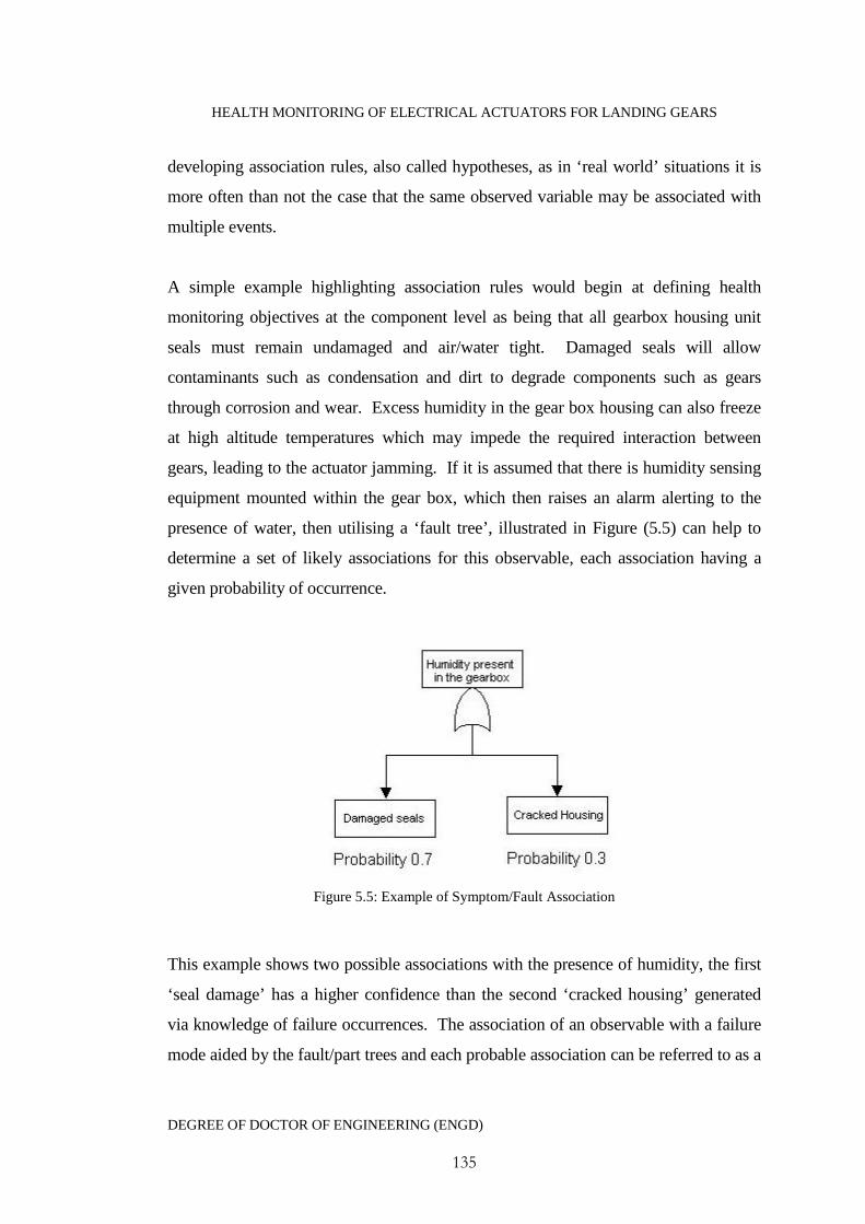
HEALTH MONITORING OF ELECTRICAL ACTUATORS FOR LANDING GEARS
DEGREE OF DOCTOR OF ENGINEERING (ENGD)
135
developing association rules, also called hypotheses, as in ‘real world’ situations it is
more often than not the case that the same observed variable may be associated with
multiple events.
A simple example highlighting association rules would begin at defining health
monitoring objectives at the component level as being that all gearbox housing unit
seals must remain undamaged and air/water tight. Damaged seals will allow
contaminants such as condensation and dirt to degrade components such as gears
through corrosion and wear. Excess humidity in the gear box housing can also freeze
at high altitude temperatures which may impede the required interaction between
gears, leading to the actuator jamming. If it is assumed that there is humidity sensing
equipment mounted within the gear box, which then raises an alarm alerting to the
presence of water, then utilising a ‘fault tree’, illustrated in Figure (5.5) can help to
determine a set of likely associations for this observable, each association having a
given probability of occurrence.
Figure 5.5: Example of Symptom/Fault Association
This example shows two possible associations with the presence of humidity, the first
‘seal damage’ has a higher confidence than the second ‘cracked housing’ generated
via knowledge of failure occurrences. The association of an observable with a failure
mode aided by the fault/part trees and each probable association can be referred to as a
HEALTH MONITORING OF ELECTRICAL ACTUATORS FOR LANDING GEARS
DEGREE OF DOCTOR OF ENGINEERING (ENGD)
136
likely hypothesis. Determining the associations is one of the initial tasks in data
fusion problem development; this is then followed by the following sub-tasks
1. Hypothesis generation: the use of sensor data to generate possible associations
2. Hypothesis evaluation: here the level of support for each association is
determined
3. Hypothesis selection: the optimal association rule is selected
5.5.3 Hypothesis Generation
The use of data mining methods is a popular choice in determining optimal
associations. These include case based reasoning and decision trees. The use of
decision trees as a data mining methodology provides optimal associations of any
sensor data to the observed phenomena. Unlike case-based reasoning approaches to
fault diagnoses, decision trees cover all anticipated faults and failures regardless if
they have occurred before or not. This is important if the system is new and
insufficient historical data concerning past events is available. As the lifetime of the
system increases and more failure occurrences are recorded case-based reasoning can
become a more optimal way of generating hypothesis. Data mining forms a ‘feedback
loop’ with the health monitoring modules by searching known information to form
hypothesis and identifies the important sensor data to be evaluated.
There are two knowledge engineering methods used in conjunction with data mining
techniques are useful in generating association rules (hypothesis), these are backward
and forward chaining. To highlight these methods let it be considered that there is a
defined list of rules associating a set of symptoms (extracted from sensor signals, such
as temperature or vibrations) to failure modes in the form
R₁: IF Gearbox has failed–THEN Actuator jams

HEALTH MONITORING OF ELECTRICAL ACTUATORS FOR LANDING GEARS
DEGREE OF DOCTOR OF ENGINEERING (ENGD)
137
R₂: IF Motor has failed – THEN Actuator jams
R₃: IF Gear tooth has broken –THEN Gearbox has failed
R₄: IF– Motor bearings are seized THEN Motor has failed
R₅: IF symptoms s₁, s₂ and s₃ are observed - THEN Gear tooth has broken
R₆: IF symptoms s₄, s₅ and s₆ are observed – THEN Motor bearings are seized
The approach known as backward chaining where the mining of the rule base begins
with a consequence which is a known occurred failure and searches out the rules until
an antecedent (fault evidence) is found to be true. In this example the fact that the
actuator has jammed is known to have occurred and is the consequence of a failed
component. Backward chaining will work through the rules in the following way
R₁→R₃→R₅, or R₂→ R₄→R₆, hence in this example we have two possible
hypotheses each with a set of symptoms to be evaluated. As this example shows
backward-chaining is a goal driven process, in this case the goal is determining the
cause of an actuator jam.
In a landing gear system however it would be desirable to be able to detect these
symptoms to aid in determining the onset of damage before the event actually occurs.
Following a reverse process known as forward chaining which is much more data-
driven, that is using data to infer faults and further possible consequences. Using the
above example rules the system begins with a set of observed symptoms which are
known to be true; the rule base is then searched until a matching consequence (failure
mode) is found giving association rules following the paths R₅ → R₃→ R₁ and
R₆→R₄→ R₂.
5.5.4 Hypothesis Evaluation
Once a set of hypotheses have been formulated then they need to be evaluated to
determine the level of support for each of them, this is given in the form of a
probability of occurrence. This support is determined through domain knowledge and
the modelling of specific sensor-to-phenomena relationships. Let’s say, for example,

HEALTH MONITORING OF ELECTRICAL ACTUATORS FOR LANDING GEARS
DEGREE OF DOCTOR OF ENGINEERING (ENGD)
138
that the proximity sensors present on the landing gears do not detect a landing gear
uplock, indicating that the retraction actuator has jammed. There are a variety of
faults at the component level which may have attributed to this platform level failure
mode. Following on from hypothesis generation, failure rates/probabilities of
components can be used in tangent with the decision tree to generate a measure of
confidence, in the form of a probability that that fault mode has occurred.
For simplistic example, the generated hypothesis of the cause of an actuator jam is
either broken gears housed within the gear box, or due to seized bearings within the
roller screw system. Therefore the following hypothesis can be evaluated:
Landing gear failed to retract due to an actuator jam resulting from gear box failure
due to seized gears caused through a broken gear tooth – support X
OR
Landing gear failed to retract due to an actuator jam resulting from roller screw
failure due to a seized actuator nut caused through bearing damage – support Y
5.5.5 Hypothesis Selection
Measures of support and uncertainty in the diagnostics can be used to rank the various
hypotheses in order of the level of support. The most likely hypothesis would then be
the diagnosis with the highest support and lowest uncertainty. If a clear diagnosis
cannot be made, then at this stage it may be necessary to improve the confidence level
by incorporating heuristic symptoms, past maintenance histories and/or further fault
statistics
5.6 Estimation
Once the most probable hypothesis has been selected, it is then necessary to make an
estimate representing the degree of damage. This is performed by a model or
algorithm capable of merging the different data sets containing representations of the
most probable fault selected through the association process. The output therefore
will be a fused estimated representation of the condition of a particular actuator
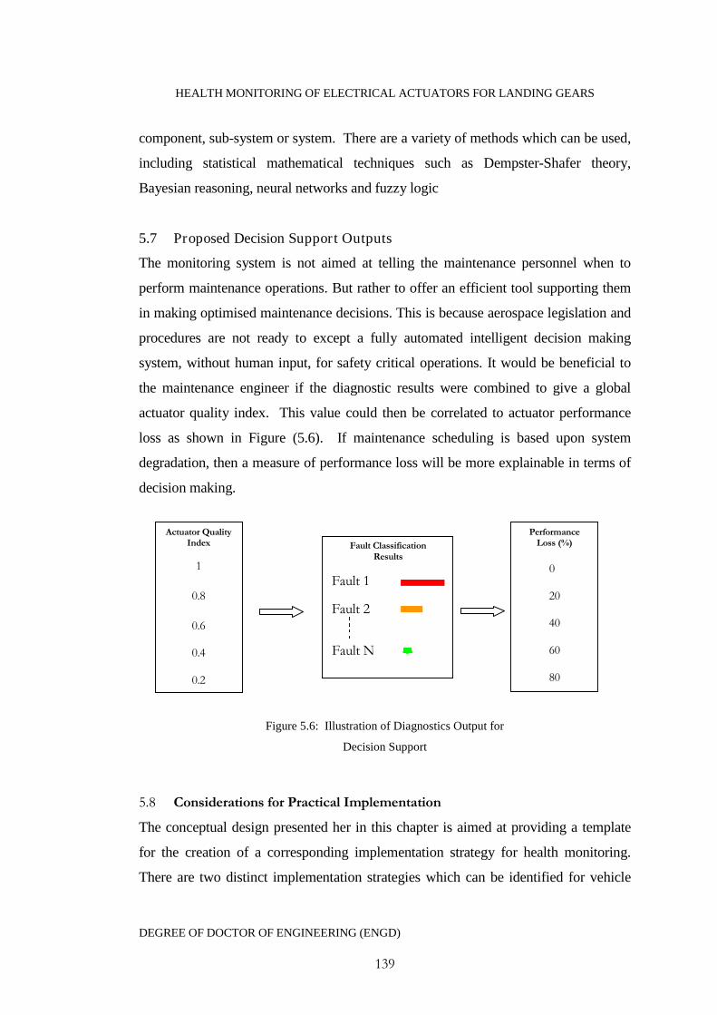
HEALTH MONITORING OF ELECTRICAL ACTUATORS FOR LANDING GEARS
DEGREE OF DOCTOR OF ENGINEERING (ENGD)
139
component, sub-system or system. There are a variety of methods which can be used,
including statistical mathematical techniques such as Dempster-Shafer theory,
Bayesian reasoning, neural networks and fuzzy logic
5.7 Proposed Decision Support Outputs
The monitoring system is not aimed at telling the maintenance personnel when to
perform maintenance operations. But rather to offer an efficient tool supporting them
in making optimised maintenance decisions. This is because aerospace legislation and
procedures are not ready to except a fully automated intelligent decision making
system, without human input, for safety critical operations. It would be beneficial to
the maintenance engineer if the diagnostic results were combined to give a global
actuator quality index. This value could then be correlated to actuator performance
loss as shown in Figure (5.6). If maintenance scheduling is based upon system
degradation, then a measure of performance loss will be more explainable in terms of
decision making.
Figure 5.6: Illustration of Diagnostics Output for
Decision Support
5.8 Considerations for Practical Implementation
The conceptual design presented her in this chapter is aimed at providing a template
for the creation of a corresponding implementation strategy for health monitoring.
There are two distinct implementation strategies which can be identified for vehicle
Fault ClassificationResults
Fault 1
Fault 2
Fault N
PerformanceLoss (%)
0
20
40
60
80
Actuator QualityIndex
1
0.8
0.6
0.4
0.2
HEALTH MONITORING OF ELECTRICAL ACTUATORS FOR LANDING GEARS
DEGREE OF DOCTOR OF ENGINEERING (ENGD)
140
health monitoring (Kidd 2006) and adapted to the specific case of landing gear
actuator monitoring.
5.8.1 Service bay implemented
One of the options for health monitoring implementation is the case where all of the
health monitoring and diagnostics is performed at a maintenance service bay. In this
strategy the aircrafts landing gear would be put through a series of on wing tests as is
currently the case, for example, multiple retraction/extension cycles under a variety of
loading conditions. The data which is then obtained would be processed by the health
monitoring system and algorithms, which in this case can be conveniently located on a
local computer, or even on the technicians Personal Digital Assistant (PDA). This
combined with data and information gained from the aircrafts standard Built in Tests
(BIT) and flight records, the status of the landing gear actuators health can be
assessed. The key advantages and disadvantages to this model can be summarised as
follows:
Advantages:
The health monitoring solution is not restricted by hardware issues such as
sensor weight/complexity/ability to operate in the harsh environment of the
landing gear bay. For example, specific sensors could be attached to the
actuator for the duration of the maintenance testing only. Therefore, such
methods as acoustic monitoring which are restricted for embedded health
monitoring, despite the value of information they can provide, can be utilised.
Diagnostic results can be instantly verified by the maintenance technicians and
any anomalies in the results traced back to the source. In flight embedded
monitoring requires that the on-board computing makes the decision with no
immediate human input or validation. This reliance on automated decision
making for such a safety critical process will almost certainly prove difficult to
certify under strict aerospace regulations.
HEALTH MONITORING OF ELECTRICAL ACTUATORS FOR LANDING GEARS
DEGREE OF DOCTOR OF ENGINEERING (ENGD)
141
The use of automated diagnostic tools during service bay maintenance will
almost certainly speed up the maintenance procedure. Minimising the time
that the aircraft is out of operational service.
Disadvantages
One of the key aims for health monitoring is for the reduction in scheduled and
unscheduled maintenance. In bay monitoring will almost certainly aid in
reducing unscheduled maintenance activities, but scheduled maintenance may
remain unaffected.
This model will not allow for any in flight warning system, pertaining to the
imminent failure of the landing gear actuator. However the mechanical and
electrical redundancy within the actuator system would mean that this is not
necessary as the gears are guaranteed to operate.
5.8.2 Embedded deployment
The second approach differs from the service bay deployment in that the monitoring
algorithms would be embedded within the aircraft alongside control algorithms and
BIT testing. This deployment strategy would allow for all of the processing to occur
on-board the aircraft, which would require strict consideration for hardware
requirements.
Advantages
Embedded health monitoring would allow for pre-flight warnings on the
landing gears or other monitored systems.
It would almost certainly be the most effective monitoring approach to reduce
the levels of scheduled maintenance. Maintenance operations would also be
quicker as the technical engineer can be directed immediately to the faulty
system/component based upon pre-processed information.
HEALTH MONITORING OF ELECTRICAL ACTUATORS FOR LANDING GEARS
DEGREE OF DOCTOR OF ENGINEERING (ENGD)
142
Disadvantages
The aircraft would have to be recalled every time the health monitoring
software requires updating.
There are restrictions on the approaches which can be used due to hardware
weight/certification procedures and signal processing capabilities.
5.9 Health Monitoring Acceptance Criteria and Metrics
5.9.1 Validation Procedure
An important issue in health monitoring systems is the ability to assess the
effectiveness of the system in performing its task of timely and correct diagnosis of
faults. This can be split into both technical and economic feasibility system metrics.
In terms of technical performance any health monitoring system would need to be
validated against set performance metrics. in order to do this the engineer would need
to decide on the most effective metrics for the application and set the necessary
thresholds.
The diagnostic performance would first need to be tested using experimental data
from a representative landing gear testing rig. As part of the landing gear actuators
acceptance tests it is known that they are put through a serious of destructive testing
and are tested through 10,000 on wing retraction/extension cycles. The data obtained
is useful in health monitoring validation for two reasons. Firstly if the underlying
algorithms are based upon system models, performance and control data from these
cycle tests can be used to estimate the actuators dynamic parameters and therefore
validate the model, as well as generating a database of nominal/faulty parameters.
Secondly as experimental faults are incorporated into the actuator and tested on the
landing gear rig, the ability for the health monitoring to detect/diagnose those faults
can be evaluated without risk to aircraft safety. Once these test are completed and the
health monitoring has been verified as the correct system for the application, it would
then be implemented onto a variety of aircraft for in-flight testing. In this stage of
validation the aircraft is in no way dependant on the health monitoring system for

HEALTH MONITORING OF ELECTRICAL ACTUATORS FOR LANDING GEARS
DEGREE OF DOCTOR OF ENGINEERING (ENGD)
143
safety or reliability but the aim would be to generate data on the operational
performance of the system - this is also useful in evaluating the technical value in
commercial terms of implementing the system.
There are several key aspects which need to be considered in validating the landing
gear health monitoring system,
1) Different aircraft need to be validated seperately. Failure modes in high altitude
long haul aircraft are likely to be different to low altitude short haul aircraft.
2) The operating location of the aircraft to be implemented with the health monitoring
system must be considered. Some failure modes, may generate more false alarms in
colder climates, for example lubrication will become sticky possibly generating a
false alarm indicating mechanical damage.
5.9.2 Fault Diagnostic Performance Metrics
Major accepted performance metrics for a diagnostic process are given as False
Negatives or False Positives. False negatives may present risks to the health of the
machine, with the missed fault condition leading to catastrophic failure. Also, a high
percentage of false positives is likely to result in a loss of confidence in the diagnostic
algorithms by the system operator. diagnostic algorithm performance requirements
would need to specigfy the maximum number of acceptable false positives and
negatives as a percentage of the total faultsin the monitored system over its expected
life.
Diagnostic events are therefore evaluated through a decision matrix (Liu and Motoda
1998) as shown in table 5.2

HEALTH MONITORING OF ELECTRICAL ACTUATORS FOR LANDING GEARS
DEGREE OF DOCTOR OF ENGINEERING (ENGD)
144
Table 5.2: Decision Matrix for Fault DetectionEvaluation
Outcome Fault 1F No Fault 0F Total
Positive (detected)
1Da
Number of detectedfaults
bNumber of false
alarms
a + bTotal Number of
alarms
Negative (notdetected) 0D
cNumber of missed
faults
dNumber of
correct rejections
c + dTotal number of
non-alarms
a + cTotal number of
faults
b + dTotal number ofcorrect rejections
a + b + c + dTotal number of
cases
From the matrix in table 5.2 the following metrics can be calculated. The probability
of detection(POD) given a fault assess the detected faults over all potential fault cases.
ca
aFDPPOD
)/( 11 Equation 5.2
The probability of false alarm (POFA) considers the proportion of all fault-free cases
that trigger a fault alarm.
db
bFDPPOFA
)/( 01 Equation 5.3
A metric of accuracy would need to be used to measure the effectiveness of any
diagnostics system or algorithm in its ability to correctly distinguish between a fault-
present and fault-free condition. The accuracy metric (Equation 5.4) uses all of the
data available for analysis (both fault and no-fault)
dcba
daFDFDPAccuracy
)/&/( 0011 Equation 5.4
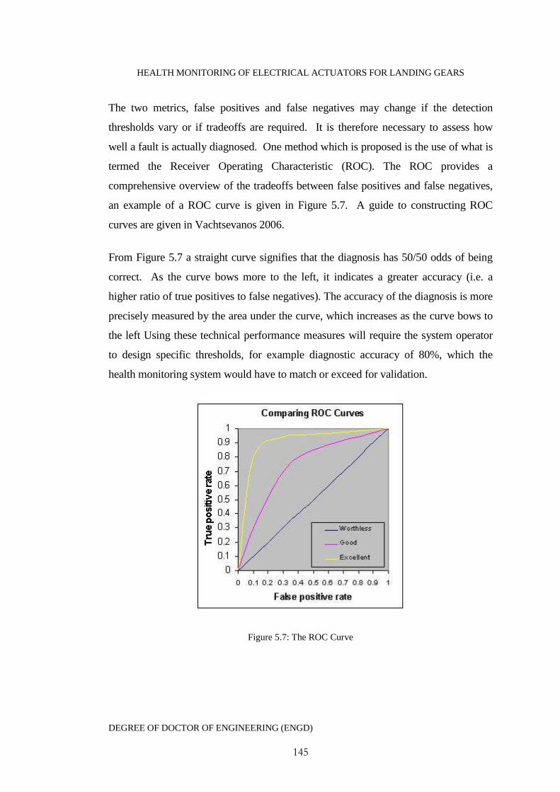
HEALTH MONITORING OF ELECTRICAL ACTUATORS FOR LANDING GEARS
DEGREE OF DOCTOR OF ENGINEERING (ENGD)
145
The two metrics, false positives and false negatives may change if the detection
thresholds vary or if tradeoffs are required. It is therefore necessary to assess how
well a fault is actually diagnosed. One method which is proposed is the use of what is
termed the Receiver Operating Characteristic (ROC). The ROC provides a
comprehensive overview of the tradeoffs between false positives and false negatives,
an example of a ROC curve is given in Figure 5.7. A guide to constructing ROC
curves are given in Vachtsevanos 2006.
From Figure 5.7 a straight curve signifies that the diagnosis has 50/50 odds of being
correct. As the curve bows more to the left, it indicates a greater accuracy (i.e. a
higher ratio of true positives to false negatives). The accuracy of the diagnosis is more
precisely measured by the area under the curve, which increases as the curve bows to
the left Using these technical performance measures will require the system operator
to design specific thresholds, for example diagnostic accuracy of 80%, which the
health monitoring system would have to match or exceed for validation.
Figure 5.7: The ROC Curve

HEALTH MONITORING OF ELECTRICAL ACTUATORS FOR LANDING GEARS
DEGREE OF DOCTOR OF ENGINEERING (ENGD)
146
5.9.3 Technical Value
The benefits which are achieved through accurate detection and diagnosis of faults
need to be weighed against the costs associated with false alarms, innacurate
diagnosis, costs and resource rquirements of implementing and operating the health
monitoring system. A metric for the technical value of a health monitoring system in a
particular application is the summation of all the benefits which it provides over all of
the failure modes which it has been designed to diagnose minus the
implementation/operating/maintenance costs. A total value equation (Vachtsevanos
2006) is given as:
))(1()(ValueTech 1 PPPIDP Dff Equation 5.5
fP =probability of failure occurrence
D = overall detection confidence score
=savings realised by detecting a fault prior to failure
I = overall isolation confidence metric score
= savings realised through automated isolation of a fault
DP = false positive detection metric score
= cost associated with false positive detection
1P = false positive isolation metric score
= cost associated with a false positive isolation
Therefore the total value of the health monitoring system is given by:
ModesFailure
)1(ValueTech cPOATOTAL Equation 5.6
A = acquisition and implementation costs
O = life-cycle operation and maintenance costs
cP = computer resource and requirements score
= cost of computing systems

HEALTH MONITORING OF ELECTRICAL ACTUATORS FOR LANDING GEARS
DEGREE OF DOCTOR OF ENGINEERING (ENGD)
147
For all of these metrics, a low score would indicate an undesirable result and a high
score indicates a desirable one. Equations 5.5 and 5.6 therefore illustrate the necessity
in applying tradeoffs between differing metrics in order to obtain an acceptable overall
value of the health monitoring system.
5.10 Conclusions
Before a practical implementation strategy can be implemented a conceptual
framework which provides descriptions of the key modules and guidelines to their use
is created as a health monitoring system template. In this work this template has been
constructed with considerations on the requirements for the actuator health monitoring
system to allow the integration of an application specific health monitoring system.
The framework discussed in this chapter is based around the concept of data fusion
and discusses the key areas such as generic inputs, data association, hypothesis
generation/evaluation/selection and proposed decision outputs. The frameworks
objective does not provide detailed recommendations on specific hardware or software
based strategies but rather acts as a kind of methodology in health monitoring design.
There are still a variety of key design issues which remain unanswered and will need
to be tackled as part of this framework these can be identified are as follows:
Providing a detailed and accurate analysis of all the potential failure modes
relevant to a particular component or assembly.
Modelling the influence of one component failure over another. This therefore
requires a comprehensive understanding of component - component
interaction.
For the introduction of health monitoring into a vehicle platform considerations need
to be made on the deployment strategy. There are two separate possibilities for this.
The first is dependent on the monitoring algorithms and decision support to be made
at a maintenance service bay, where the monitoring software is located. The second

HEALTH MONITORING OF ELECTRICAL ACTUATORS FOR LANDING GEARS
DEGREE OF DOCTOR OF ENGINEERING (ENGD)
148
approach would see the health monitoring algorithms embedded onto the aircraft
alongside control algorithms and BIT testing. Both deployment strategies have a
variety of advantages and disadvantages which have been discussed but no single
strategy is committed to as part of this work. It is highly likely that for effective
aerospace vehicle monitoring a hybrid of the two deployment strategies would be a
natural approach.
Before a health monitoring system can be accepted it must be verified against a set of
pre-determined performance metrics in order to justify its acceptance. Diagnostic
performance metrics, which is the ability to accurately diagnose faults, assessment
would be through consideration of the number of missed alarms or false alarms in
order to generate a ROC curve. The use of the ROC curve allows the health
monitoring designer to gauge the overall diagnostic accuracy of the system - which
would need to match a set threshold criteria. The second metric which has been
discussed is a method of providing the overall technical value of the health monitoring
system. This finds the difference between cost savings over all possible detectable
failure modes and the costs of implementation and upkeep. This is an important
metric which must exceed the value of not having the monitoring system.
5.11 References
Kidd, M., (2006), 'Automotive condition monitoring using standard vehicle
Architecture', Engineering Doctorate Thesis, University of Manchester, UK
Liu, H., Motoda, H., (1998), "Feature selection for knowledge discovery and data
mining", Boston: Kluwer Academic.
Phillips, P., Diston, D., Payne, J., Pandya, S., Starr, A. (2008), 'The application of
condition monitoring methodologies for certification of reliability in electric landing
gear actuators', in The 5th International Conference on Condition Monitoring and
Machine Failure Technologies. Edinburgh, UK.

HEALTH MONITORING OF ELECTRICAL ACTUATORS FOR LANDING GEARS
DEGREE OF DOCTOR OF ENGINEERING (ENGD)
149
Raheja, D. (2006), 'Data fusion/data mining-based architecture for condition-based
maintenance', International Journal of Production Research, Vol 44. No 14. pp. 2869-
2887.
Vachtsevanos, G., Lewis, F., Roemer, M., Hess, A., WU, B. (2006), 'Intelligent Fault
Diagnosis and Prognosis for Engineering Systems' John Wiley & Sons , INC.

HEALTH MONITORING OF ELECTRICAL ACTUATORS FOR LANDING GEARS
DEGREE OF DOCTOR OF ENGINEERING (ENGD)
150
C h a p t e r 6 : A p p l i c a t i o n o f F u z z y L o g i c a n d
P r i n c i p a l C o m p o n e n t A n a l y s i s f o r D e t e r m i n i n g
P r o c e s s Q u a l i t y
6.1 Introduction
The previous chapter provided the framework constructed for use in developing
actuator fault diagnostics. The framework reviewed the factors relating to the
information which should be gained from a monitoring system for effective
maintenance support. This chapter proposes a mathematical algorithm which
addresses one way in which these outputs can be achieved, whilst keeping within the
design requirements for the monitoring system (Phillips and Diston 2010).
The monitoring outputs for decision support are categorised as 'fault detection',
represented by overall actuator operating quality and 'fault diagnostics' represented by
a ranking of probabilities of specific faults occurring. Through estimating the overall
actuator process quality, then the affects that individual faults are having on the
actuator systems ability to perform to a specific requirement are identifiable. The fault
detection within this research is based upon the use of Principal Component Analysis
(PCA) which uses only the actuators dynamic process data, obtained as part of the
actuators control system. The use of PCA allows reductions in the size of the data set
and generates statistics, which are analysed through the use of a fuzzy logic rule base
to provide a quantified performance quality. This actuator quality can then be
monitored to ensure that it does not fall below a predefined quality threshold, which if
it does full fault diagnostics would be initiated.
This chapter presents the formulisation of the fault detection algorithm and provides
the results of an experimental demonstration. The experiments make use of an off-
the-shelf bench top actuator with several degrees of lubricant degradation
incorporated into the actuator gears and screw assembly. The experiment highlights
the potential of the algorithm in fault detection for lubrication faults in the actuators.
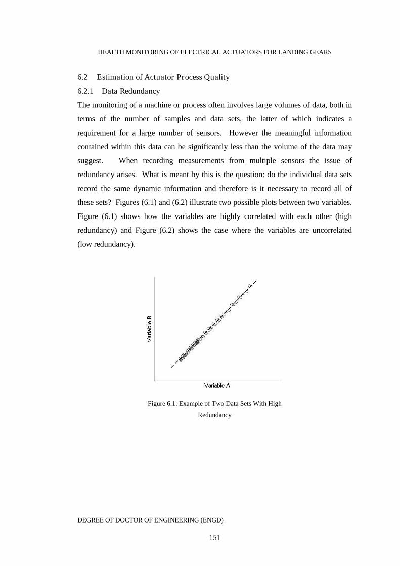
HEALTH MONITORING OF ELECTRICAL ACTUATORS FOR LANDING GEARS
DEGREE OF DOCTOR OF ENGINEERING (ENGD)
151
6.2 Estimation of Actuator Process Quality
6.2.1 Data Redundancy
The monitoring of a machine or process often involves large volumes of data, both in
terms of the number of samples and data sets, the latter of which indicates a
requirement for a large number of sensors. However the meaningful information
contained within this data can be significantly less than the volume of the data may
suggest. When recording measurements from multiple sensors the issue of
redundancy arises. What is meant by this is the question: do the individual data sets
record the same dynamic information and therefore is it necessary to record all of
these sets? Figures (6.1) and (6.2) illustrate two possible plots between two variables.
Figure (6.1) shows how the variables are highly correlated with each other (high
redundancy) and Figure (6.2) shows the case where the variables are uncorrelated
(low redundancy).
Figure 6.1: Example of Two Data Sets With High
Redundancy
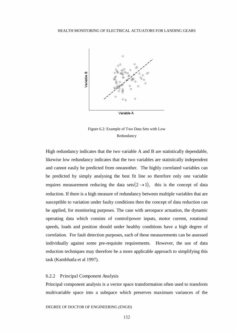
HEALTH MONITORING OF ELECTRICAL ACTUATORS FOR LANDING GEARS
DEGREE OF DOCTOR OF ENGINEERING (ENGD)
152
Figure 6.2: Example of Two Data Sets with Low
Redundancy
High redundancy indicates that the two variable A and B are statistically dependable,
likewise low redundancy indicates that the two variables are statistically independent
and cannot easily be predicted from oneanother. The highly correlated variables can
be predicted by simply analysing the best fit line so therefore only one variable
requires measurement reducing the data sets 12 , this is the concept of data
reduction. If there is a high measure of redundancy between multiple variables that are
susceptible to variation under faulty conditions then the concept of data reduction can
be applied, for monitoring purposes. The case with aerospace actuation, the dynamic
operating data which consists of control/power inputs, motor current, rotational
speeds, loads and position should under healthy conditions have a high degree of
correlation. For fault detection purposes, each of these measurements can be assessed
individually against some pre-requisite requirements. However, the use of data
reduction techniques may therefore be a more applicable approach to simplifying this
task (Kambhatla et al 1997).
6.2.2 Principal Component Analysis
Principal component analysis is a vector space transformation often used to transform
multivariable space into a subspace which preserves maximum variances of the

HEALTH MONITORING OF ELECTRICAL ACTUATORS FOR LANDING GEARS
DEGREE OF DOCTOR OF ENGINEERING (ENGD)
153
original space, but with a reduced number of dimensions (Jackson 2003). The
measured variables in the original space are usually highly correlated, so PCA can be
defined as a linear transformation of the original correlated data into a new set of
uncorrelated data that explains the trend in the process. The formulation of a PCA is
as follows. First a new mn matrix is defined as Tm1 xxX . Each row of
X corresponds to measurements of a particular type )( ix and the columns correspond
to a set of measurements from a trial. The covariance matrix of this data set can be
written as
TX XXC .
1
1
nEquation 6.1
Equation 1
The factor1
1
nis a constant for normalisation. The covariance matrix XC captures
all of the correlations between all possible pairs of measurements and reflects the
noise and redundancy in the measurements. It has the following properties:
XC is a square mm matrix
The diagonal terms of XC are the variance of particular measurement types.
Large values correspond to interesting dynamics and small values correspond
to noise.
The off-diagonal terms of XC are the covariance between measurement types.
High values correspond to high redundancy and low values low redundancy.
The first step is to calculate PCA is to construct the covariance matrix given
inEquation 6.1 and performe the Singular Value Decomposition (SVD) on the matrix
as follows:
HEALTH MONITORING OF ELECTRICAL ACTUATORS FOR LANDING GEARS
DEGREE OF DOCTOR OF ENGINEERING (ENGD)
154
TΛVVCX . Equation 6.2
Where Λ is a diagonal matrix containing the eigenvalues of XC in decreasing order
( 021 m ). The columns of the matrix Vare the eigenvectors of XC . A
transformation matrix P of dimensions am , where a is the chosen number of
eigenvectors which are used as the principal components, can be generated to
transform the original measured variable space into the reduced dimension space
PXT . Equation 6.3
The matrix P is known as the loading matrix and T as the score matrix. The elements
of T are the values of the original measured variables that have been transformed into
the reduced dimension space.
6.2.3 Choosing the Principle Components
For PCA to be successful in a health monitoring context then the appropriate
number of principle components must be selected. In this instance a method known
as Cumulative Percent Variance (CPV) is used to calculate the correct number in
which to project the data onto. This approach chooses the number of principle
components (a) for a particular measure of percentage variance %)95)(i.e.( aCPV .
The CPV is calculated using:
m
jj
a
jj
CPV
1
1
Equation 6.4

HEALTH MONITORING OF ELECTRICAL ACTUATORS FOR LANDING GEARS
DEGREE OF DOCTOR OF ENGINEERING (ENGD)
155
6.2.4 Generating Performance Statistics
Traditional fault detection based upon PCA is achieved through the generation of a
statistic known as a Squared Prediction Error (SPE). The SPE is aimed at capturing
any small variations between the PCA model data and the next set of process
measurements. Under nominal conditions the SPE will remain close to zero but any
variation in the process will lead to a positive or negative deviation, which if a set
threshold is breached an alarm is raised. The SPE can be calculated in the following
manner.
From Equation 6.3 it can be seen that the scores can be transformed into m-
dimensional observational space by:
TPTX .ˆ Equation 6.5
The difference between the observation space X̂ and the original data space
X represented by the residual matrix E which captures the variations in the
observation space spanned by the loading vectors associated with the m-smallest
singular values.
XXE ˆ Equation 6.6
The SPE is therefore defined by:
EEQ TT Equation 6.7
Using a SPE the process is considered normal if the process is within an upper
control limit represented by
2δQ Equation 6.8
HEALTH MONITORING OF ELECTRICAL ACTUATORS FOR LANDING GEARS
DEGREE OF DOCTOR OF ENGINEERING (ENGD)
156
A second statistic is calculated using a 2T - Hotellings statistic. In this work we can
consider the scores to be bounded by an elliptical threshold, which is regarded as the
confidence region which is defined as (Palma et al. 2005).
2
2
22
1
21
Ttt
Equation 6.9
In Equation 6.9 nt are the projections along the orthogonal axes defined by the
loading vectors, 1 and 2 are the principle eigenvalues (Note that Equation 6.9
represents the case where the number of principle components a=2). The 2T
statistics threshold is defined by Equation 6.10. The value ),( anaF is obtainable
from an F-distribution table for a certain level of significance (Jackson 2003).
),()(
)1)(1(2 anaFann
nnaT
Equation 6.10
In this work both the Q and 2T statistics will be combined together in order to
generate an overall measure of process quality.
6.2.5 Fuzzy Logic Classification
After the appropriate features have been identified then an inference to their meanings
has to be made. An appropriate technique, which fits well here, is the use of fuzzy
logic classification (Bartys et al. 2005) which can deal with reasoning that is
approximate rather than precise. There are three stages to classification via fuzzy logic
(Leekwijick & kerre 1999). The first is to convert the input variables into fuzzy
variables (fuzzification); the second is the evaluation of a fuzzy rule base and finally
converting the fuzzy outputs back into crisp numbers (defuzzification). The first stage
begins with the designing of individual membership functions. Here the variables are
mapped to predetermined membership functions and are converted into linguistic
variables, such as Okay, Medium or High as illustrated in Figure (6.3).
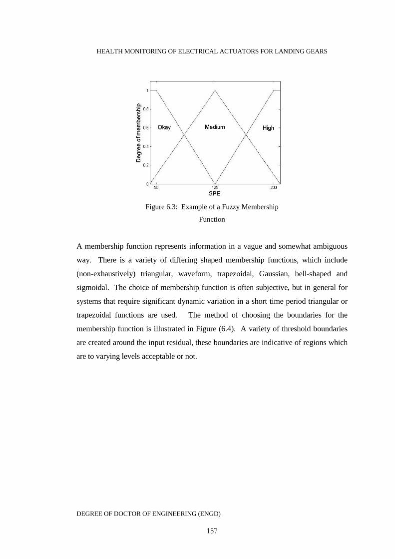
HEALTH MONITORING OF ELECTRICAL ACTUATORS FOR LANDING GEARS
DEGREE OF DOCTOR OF ENGINEERING (ENGD)
157
Figure 6.3: Example of a Fuzzy Membership
Function
A membership function represents information in a vague and somewhat ambiguous
way. There is a variety of differing shaped membership functions, which include
(non-exhaustively) triangular, waveform, trapezoidal, Gaussian, bell-shaped and
sigmoidal. The choice of membership function is often subjective, but in general for
systems that require significant dynamic variation in a short time period triangular or
trapezoidal functions are used. The method of choosing the boundaries for the
membership function is illustrated in Figure (6.4). A variety of threshold boundaries
are created around the input residual, these boundaries are indicative of regions which
are to varying levels acceptable or not.
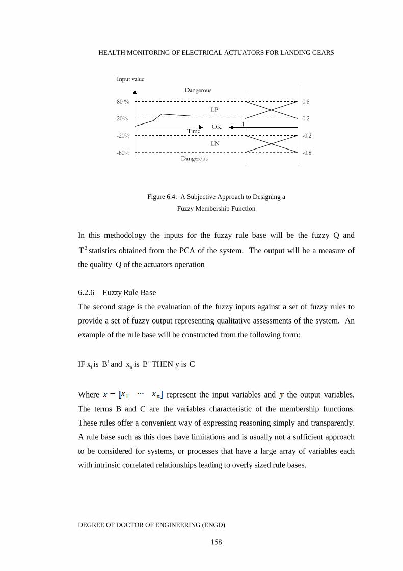
HEALTH MONITORING OF ELECTRICAL ACTUATORS FOR LANDING GEARS
DEGREE OF DOCTOR OF ENGINEERING (ENGD)
158
Figure 6.4: A Subjective Approach to Designing a
Fuzzy Membership Function
In this methodology the inputs for the fuzzy rule base will be the fuzzy Q and
2T statistics obtained from the PCA of the system. The output will be a measure of
the quality Q of the actuators operation
6.2.6 Fuzzy Rule Base
The second stage is the evaluation of the fuzzy inputs against a set of fuzzy rules to
provide a set of fuzzy output representing qualitative assessments of the system. An
example of the rule base will be constructed from the following form:
IF 1x is 1B and nx is nB THEN y is C
Where represent the input variables and the output variables.
The terms B and C are the variables characteristic of the membership functions.
These rules offer a convenient way of expressing reasoning simply and transparently.
A rule base such as this does have limitations and is usually not a sufficient approach
to be considered for systems, or processes that have a large array of variables each
with intrinsic correlated relationships leading to overly sized rule bases.
Input value
-0.8
0.8
0.2
-0.2
1
80 %
-80%
20%
-20%Time
OK
LN
LP
Dangerous
Dangerous
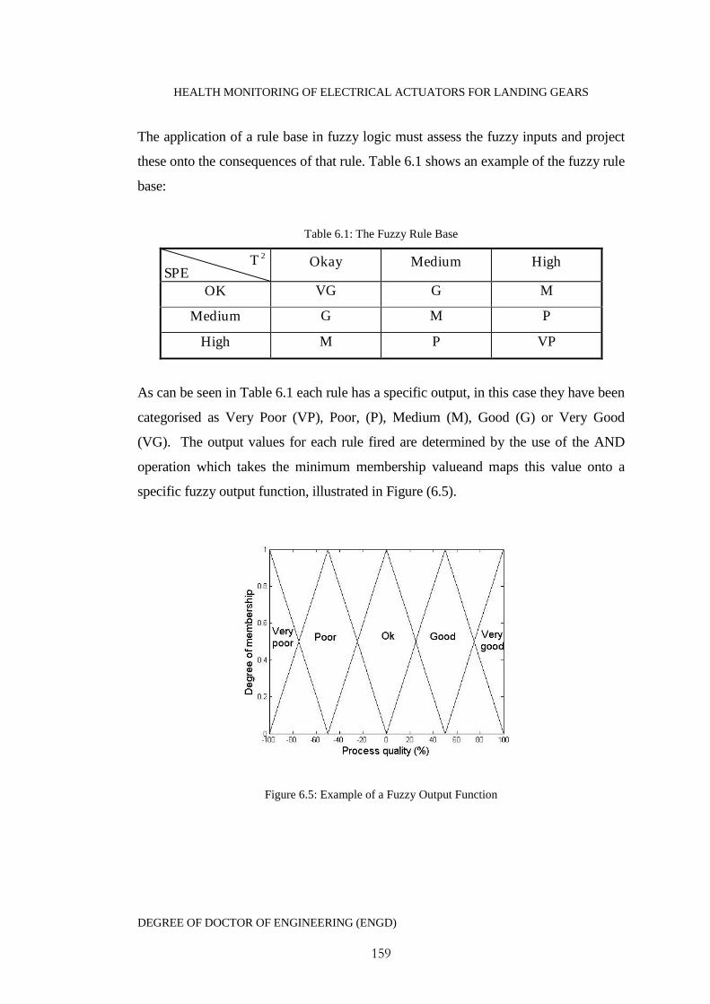
HEALTH MONITORING OF ELECTRICAL ACTUATORS FOR LANDING GEARS
DEGREE OF DOCTOR OF ENGINEERING (ENGD)
159
The application of a rule base in fuzzy logic must assess the fuzzy inputs and project
these onto the consequences of that rule. Table 6.1 shows an example of the fuzzy rule
base:
Table 6.1: The Fuzzy Rule Base
Okay Medium High
OK VG G M
Medium G M P
High M P VP
As can be seen in Table 6.1 each rule has a specific output, in this case they have been
categorised as Very Poor (VP), Poor, (P), Medium (M), Good (G) or Very Good
(VG). The output values for each rule fired are determined by the use of the AND
operation which takes the minimum membership valueand maps this value onto a
specific fuzzy output function, illustrated in Figure (6.5).
Figure 6.5: Example of a Fuzzy Output Function
SPE
2T
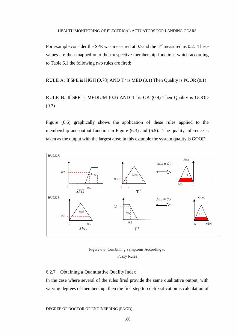
HEALTH MONITORING OF ELECTRICAL ACTUATORS FOR LANDING GEARS
DEGREE OF DOCTOR OF ENGINEERING (ENGD)
160
For example consider the SPE was measured at 0.7and the 2T measured as 0.2. These
values are then mapped onto their respective membership functions which according
to Table 6.1 the following two rules are fired:
RULE A: If SPE is HIGH (0.78) AND 2T is MED (0.1) Then Quality is POOR (0.1)
RULE B: If SPE is MEDIUM (0.3) AND 2T is OK (0.9) Then Quality is GOOD
(0.3)
Figure (6.6) graphically shows the application of these rules applied to the
membership and output function in Figure (6.3) and (6.5). The quality inference is
taken as the output with the largest area; in this example the system quality is GOOD.
Figure 6.6: Combining Symptoms According to
Fuzzy Rules
6.2.7 Obtaining a Quantitative Quality Index
In the case where several of the rules fired provide the same qualitative output, with
varying degrees of membership, then the first step too defuzzification is calculation of
0 0.6SPE
High0.7
2T
Med
0.3
RULE B
RULE APoor
0.3
-100 0
0.1
Good
Min = 0.1
Min = 0.3
SPE0.60 +100
Med
0.1
0.20
2T
0.2
0.9
OK
00
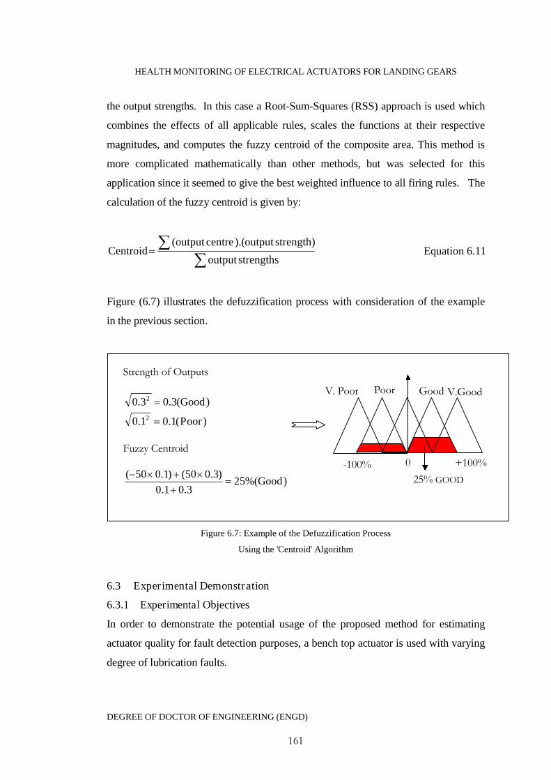
HEALTH MONITORING OF ELECTRICAL ACTUATORS FOR LANDING GEARS
DEGREE OF DOCTOR OF ENGINEERING (ENGD)
161
the output strengths. In this case a Root-Sum-Squares (RSS) approach is used which
combines the effects of all applicable rules, scales the functions at their respective
magnitudes, and computes the fuzzy centroid of the composite area. This method is
more complicated mathematically than other methods, but was selected for this
application since it seemed to give the best weighted influence to all firing rules. The
calculation of the fuzzy centroid is given by:
strengthsoutput
strength)output).(centreoutput(Centroid Equation 6.11
Figure (6.7) illustrates the defuzzification process with consideration of the example
in the previous section.
Figure 6.7: Example of the Defuzzification Process
Using the 'Centroid' Algorithm
6.3 Experimental Demonstration
6.3.1 Experimental Objectives
In order to demonstrate the potential usage of the proposed method for estimating
actuator quality for fault detection purposes, a bench top actuator is used with varying
degree of lubrication faults.
Poor
-100% +100%
V. Poor Good V.Good
0
25% GOOD
Strength of Outputs
)(3.03.0 2 Good
)(1.01.0 2 Poor
Fuzzy Centroid
)%(253.01.0
)3.050()1.050(Good
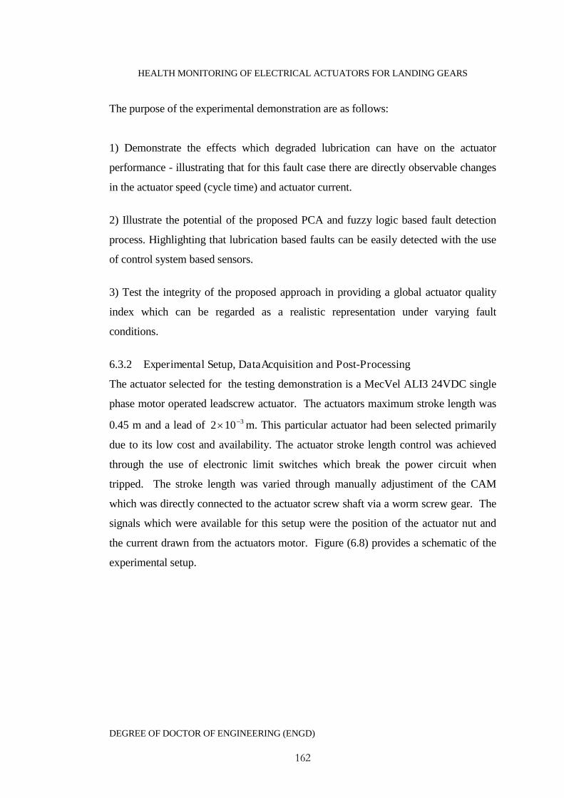
HEALTH MONITORING OF ELECTRICAL ACTUATORS FOR LANDING GEARS
DEGREE OF DOCTOR OF ENGINEERING (ENGD)
162
The purpose of the experimental demonstration are as follows:
1) Demonstrate the effects which degraded lubrication can have on the actuator
performance - illustrating that for this fault case there are directly observable changes
in the actuator speed (cycle time) and actuator current.
2) Illustrate the potential of the proposed PCA and fuzzy logic based fault detection
process. Highlighting that lubrication based faults can be easily detected with the use
of control system based sensors.
3) Test the integrity of the proposed approach in providing a global actuator quality
index which can be regarded as a realistic representation under varying fault
conditions.
6.3.2 Experimental Setup, DataAcquisition and Post-Processing
The actuator selected for the testing demonstration is a MecVel ALI3 24VDC single
phase motor operated leadscrew actuator. The actuators maximum stroke length was
0.45 m and a lead of 3102 m. This particular actuator had been selected primarily
due to its low cost and availability. The actuator stroke length control was achieved
through the use of electronic limit switches which break the power circuit when
tripped. The stroke length was varied through manually adjustiment of the CAM
which was directly connected to the actuator screw shaft via a worm screw gear. The
signals which were available for this setup were the position of the actuator nut and
the current drawn from the actuators motor. Figure (6.8) provides a schematic of the
experimental setup.
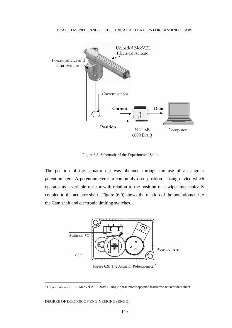
HEALTH MONITORING OF ELECTRICAL ACTUATORS FOR LANDING GEARS
DEGREE OF DOCTOR OF ENGINEERING (ENGD)
163
Figure 6.8: Schematic of the Experimental Setup
The position of the actuator nut was obtained through the use of an angular
potentiometer. A potentiometer is a commonly used position sensing device which
operates as a variable resistor with relation to the position of a wiper mechanically
coupled to the actuator shaft. Figure (6.9) shows the relation of the potentiometer to
the Cam shaft and electronic limiting switches.
Figure 6.9: The Actuator Potentiometer*
* Diagram obtained from MecVel ALI3 24VDC single phase motor operated leadscrew actuator data sheet
ComputerNI-USB6009 DAQ
Unloaded MecVELElectrical Actuator
Potentiometer andlimit switches
Current sensor
Current
Position
Data
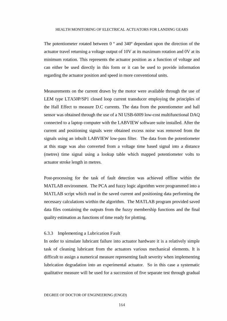
HEALTH MONITORING OF ELECTRICAL ACTUATORS FOR LANDING GEARS
DEGREE OF DOCTOR OF ENGINEERING (ENGD)
164
The potentiometer rotated between 0 º and 340º dependant upon the direction of the
actuator travel returning a voltage output of 10V at its maximum rotation and 0V at its
minimum rotation. This represents the actuator position as a function of voltage and
can either be used directly in this form or it can be used to provide information
regarding the actuator position and speed in more conventional units.
Measurements on the current drawn by the motor were available through the use of
LEM type LTA50P/SP1 closed loop current transducer employing the principles of
the Hall Effect to measure D.C currents. The data from the potentiometer and hall
sensor was obtained through the use of a NI USB-6009 low-cost multifunctional DAQ
connected to a laptop computer with the LABVIEW software suite installed. After the
current and positioning signals were obtained excess noise was removed from the
signals using an inbuilt LABVIEW low-pass filter. The data from the potentiometer
at this stage was also converted from a voltage time based signal into a distance
(metres) time signal using a lookup table which mapped potentiometer volts to
actuator stroke length in metres.
Post-processing for the task of fault detection was achieved offline within the
MATLAB environment. The PCA and fuzzy logic algorithm were programmed into a
MATLAB script which read in the saved current and positioning data performing the
necessary calculations wirthin the algorithm. The MATLAB program provided saved
data files containing the outputs from the fuzzy membership functions and the final
quality estimation as functions of time ready for plotting.
6.3.3 Implementing a Lubrication Fault
In order to simulate lubricant failure into actuator hardware it is a relatively simple
task of cleaning lubricant from the actuators various mechanical elements. It is
difficult to assign a numerical measure representing fault severity when implementing
lubrication degradation into an experimental actuator. So in this case a systematic
qualitative measure will be used for a succession of five separate test through gradual
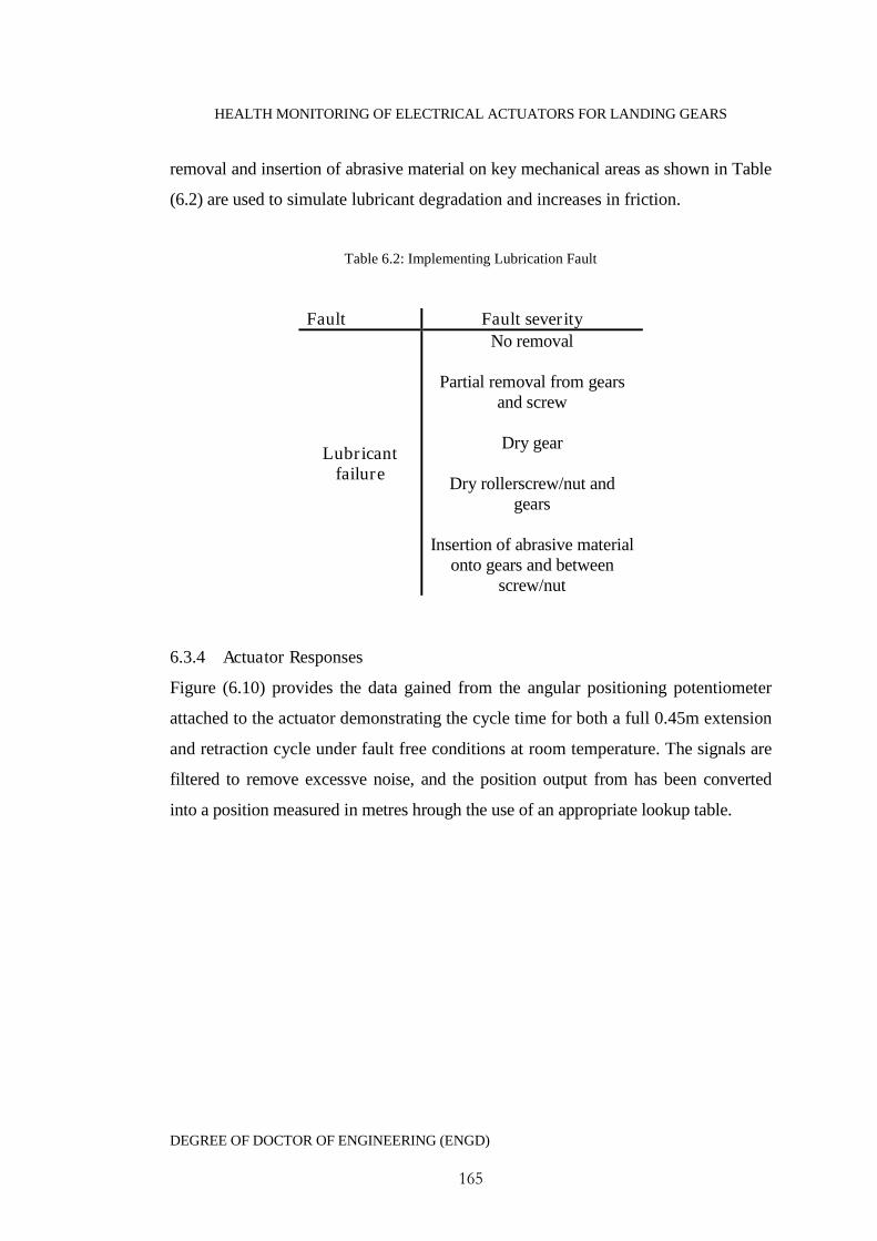
HEALTH MONITORING OF ELECTRICAL ACTUATORS FOR LANDING GEARS
DEGREE OF DOCTOR OF ENGINEERING (ENGD)
165
removal and insertion of abrasive material on key mechanical areas as shown in Table
(6.2) are used to simulate lubricant degradation and increases in friction.
Table 6.2: Implementing Lubrication Fault
Fault Fault severity
Lubricantfailure
No removal
Partial removal from gearsand screw
Dry gear
Dry rollerscrew/nut andgears
Insertion of abrasive materialonto gears and between
screw/nut
6.3.4 Actuator Responses
Figure (6.10) provides the data gained from the angular positioning potentiometer
attached to the actuator demonstrating the cycle time for both a full 0.45m extension
and retraction cycle under fault free conditions at room temperature. The signals are
filtered to remove excessve noise, and the position output from has been converted
into a position measured in metres hrough the use of an appropriate lookup table.
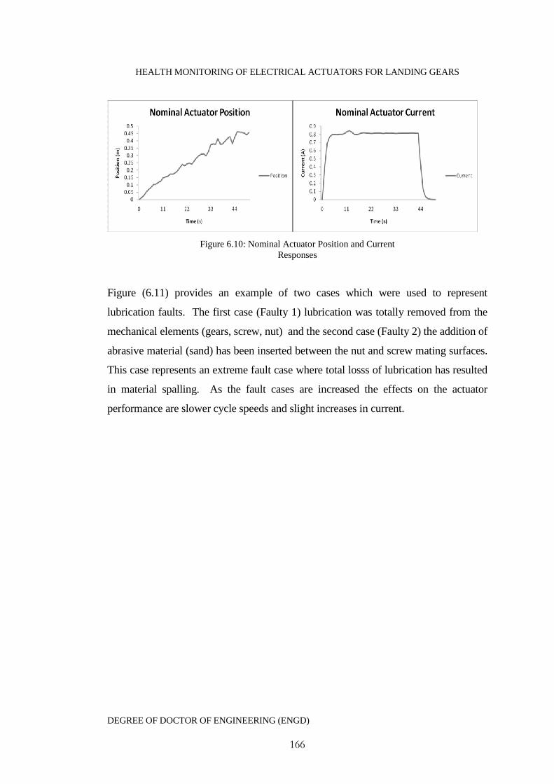
HEALTH MONITORING OF ELECTRICAL ACTUATORS FOR LANDING GEARS
DEGREE OF DOCTOR OF ENGINEERING (ENGD)
166
Figure 6.10: Nominal Actuator Position and CurrentResponses
Figure (6.11) provides an example of two cases which were used to represent
lubrication faults. The first case (Faulty 1) lubrication was totally removed from the
mechanical elements (gears, screw, nut) and the second case (Faulty 2) the addition of
abrasive material (sand) has been inserted between the nut and screw mating surfaces.
This case represents an extreme fault case where total losss of lubrication has resulted
in material spalling. As the fault cases are increased the effects on the actuator
performance are slower cycle speeds and slight increases in current.
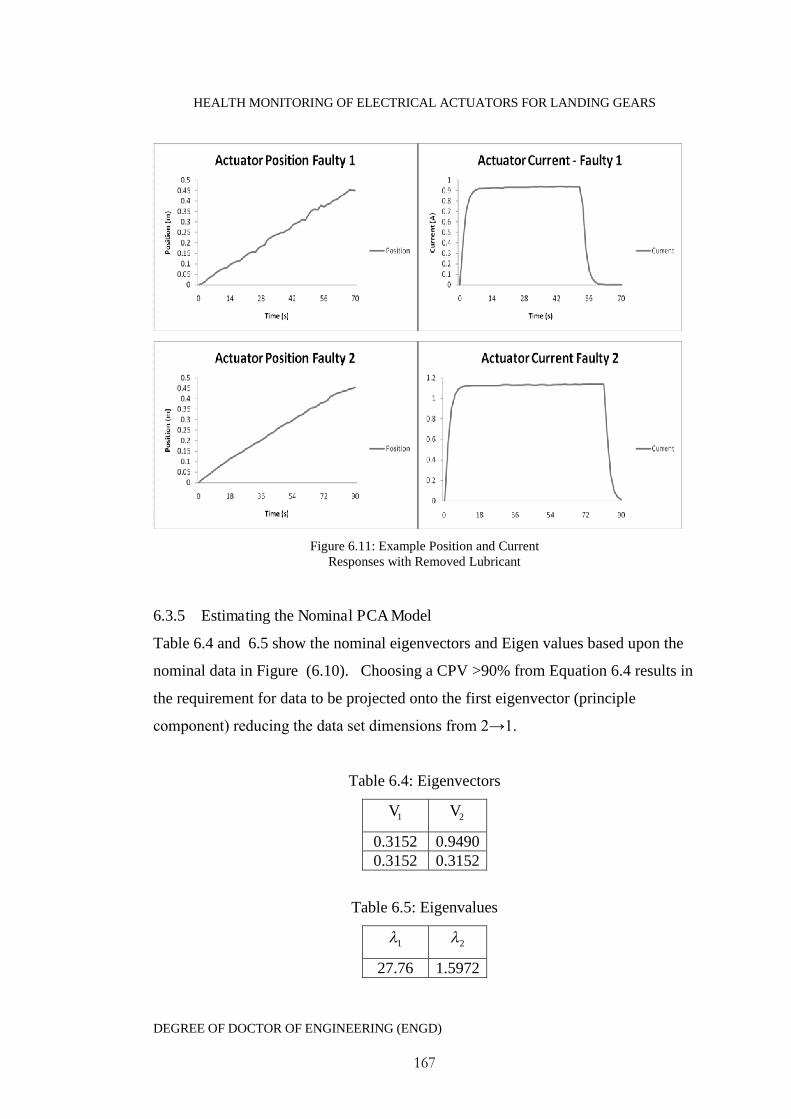
HEALTH MONITORING OF ELECTRICAL ACTUATORS FOR LANDING GEARS
DEGREE OF DOCTOR OF ENGINEERING (ENGD)
167
Figure 6.11: Example Position and CurrentResponses with Removed Lubricant
6.3.5 Estimating the Nominal PCA Model
Table 6.4 and 6.5 show the nominal eigenvectors and Eigen values based upon the
nominal data in Figure (6.10). Choosing a CPV >90% from Equation 6.4 results in
the requirement for data to be projected onto the first eigenvector (principle
component) reducing the data set dimensions from 2→1.
Table 6.4: Eigenvectors
1V 2V
0.3152 0.94900.3152 0.3152
Table 6.5: Eigenvalues
1 2
27.76 1.5972
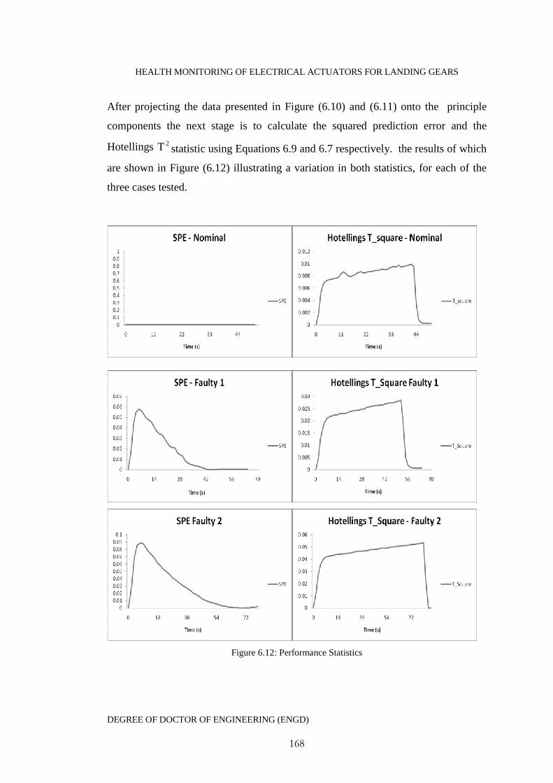
HEALTH MONITORING OF ELECTRICAL ACTUATORS FOR LANDING GEARS
DEGREE OF DOCTOR OF ENGINEERING (ENGD)
168
After projecting the data presented in Figure (6.10) and (6.11) onto the principle
components the next stage is to calculate the squared prediction error and the
Hotellings 2T statistic using Equations 6.9 and 6.7 respectively. the results of which
are shown in Figure (6.12) illustrating a variation in both statistics, for each of the
three cases tested.
Figure 6.12: Performance Statistics
HEALTH MONITORING OF ELECTRICAL ACTUATORS FOR LANDING GEARS
DEGREE OF DOCTOR OF ENGINEERING (ENGD)
169
6.3.6 Fuzzy Inference
Examination of how the performance statistics change with removal of the actuators
lubricant is used to define two triangular fuzzy membership functions similar to
Figure (6.3). The centres of the triangular membership functions used are given in
Table 6.6. Figure (6.13) shows the transformations of the SPE and 2T statistics into
fuzzy inputs.
Table 6.6: Input Membership Function Centres
Okay Medium High
2T 0 0.025 0.05
SPE 0 0.05 0.1
The fuzzy inoputs in are evaluated against a fuzzy rule base, which has five possible
outputs. These are quality is Very Good (VG), Good (G), Medium (M), Poor (P)
and Very Poor (VP). The rule base is shown in Table 6.1 and are evaluated by
calculation of a root mean square for each of the possible outcomes.
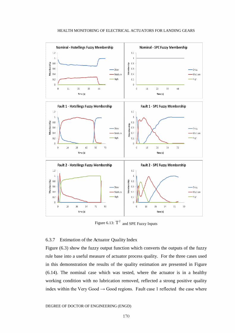
HEALTH MONITORING OF ELECTRICAL ACTUATORS FOR LANDING GEARS
DEGREE OF DOCTOR OF ENGINEERING (ENGD)
170
Figure 6.13:2T and SPE Fuzzy Inputs
6.3.7 Estimation of the Actuator Quality Index
Figure (6.3) show the fuzzy output function which converts the outputs of the fuzzy
rule base into a useful measure of actuator process quality. For the three cases used
in this demonstration the results of the quality estimation are presented in Figure
(6.14). The nominal case which was tested, where the actuator is in a healthy
working condition with no lubrication removed, reflected a strong positive quality
index within the Very Good → Good regions. Fault case 1 reflected the case where
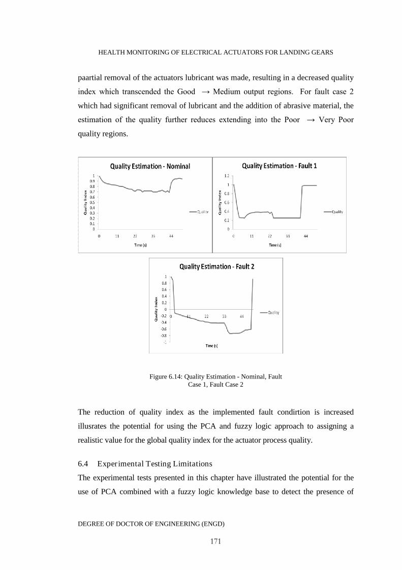
HEALTH MONITORING OF ELECTRICAL ACTUATORS FOR LANDING GEARS
DEGREE OF DOCTOR OF ENGINEERING (ENGD)
171
paartial removal of the actuators lubricant was made, resulting in a decreased quality
index which transcended the Good → Medium output regions. For fault case 2
which had significant removal of lubricant and the addition of abrasive material, the
estimation of the quality further reduces extending into the Poor → Very Poor
quality regions.
Figure 6.14: Quality Estimation - Nominal, FaultCase 1, Fault Case 2
The reduction of quality index as the implemented fault condirtion is increased
illusrates the potential for using the PCA and fuzzy logic approach to assigning a
realistic value for the global quality index for the actuator process quality.
6.4 Experimental Testing Limitations
The experimental tests presented in this chapter have illustrated the potential for the
use of PCA combined with a fuzzy logic knowledge base to detect the presence of
HEALTH MONITORING OF ELECTRICAL ACTUATORS FOR LANDING GEARS
DEGREE OF DOCTOR OF ENGINEERING (ENGD)
172
lubrication loss within an actuator system. there are however several limitations to the
procedure presented, which are as follows:
1) The actuator was not considered under any loading conditions - differing loads may
affect the operation of the actuator, so the diagnostic results under an unloaded
actuator may not be representative of a loaded actuator.
2) Considerations for the actuators operating environment, for example the actuator
has only been tested at room temperature and viscosity of lubrication is temperature
dependant and tests would need to be conducted on the range of operating
temperatures in order to assess the robustness of the fuzzy logic membership functions
and PCA performance statistics.
3) The experiment has only considered the issue of lubrication loss at three extreme
intervals, i.e. no loss, full loss, full loss plus abrasive material. This has limited the
assessment of the sensitivity of the approach and further testing would be required
which takes into account gradual lubrication loss or other fault development.
4) Only one fault condition has been considered, for full acceptance of the proposed
approaches experimental testing on a range of electrical and mechanical faults are
required.
5) With the current bench top actuator setup, it is not possible to up scale the
experimental results to the actuator system on the aircraft landing gears. A modified
rig is therefore required which is more representative of the landing gear application
so that experimental results can be upscaled.
6) it is very difficult to assign a numerical measure representing the severity of an
implemented mechanical fault. This affects the repeatability of the experiments as it
is very difficult to reproduce the same fault at the exact same magnitude.

HEALTH MONITORING OF ELECTRICAL ACTUATORS FOR LANDING GEARS
DEGREE OF DOCTOR OF ENGINEERING (ENGD)
173
6.5 Practical Considerations
One of the limitations of principle component analysis is that most aerospace
actuators operate under differing environmental conditions and modes. Therefore
conventional principle component analysis as proposed may produce false alarms
and the possibility of inaccurate results. Transitions from one operating mode to
another can have the effect of breaking the correlation between variables. Also the
loading of the landing gear actuator varies during a cycle. This may lead also lead to
inaccuracies with the approach.
There are several solutions to these issues:
1. Generate a PCA model for each operating mode or possible flight condition
2. Update the PCA model to reflect the changes in the operating modes
3. Develop PCA models to account for all operational changes
The advantages of the outlined approach as a practical solution are as follows:
Non-intrusive method with no requirement for additional sensing equipment
Reductions in data set size
The fuzzy approach allows a transparent progression from the initial data to
the final output. With decisions traceable due to the nature of a fuzzy IF-
THEN rule base.
The nature of rule bases means that in the presence of new information they
can easily be updated.
HEALTH MONITORING OF ELECTRICAL ACTUATORS FOR LANDING GEARS
DEGREE OF DOCTOR OF ENGINEERING (ENGD)
174
6.6 Conclusions
It is known that a strong correlation between the actuators process data will exist
under nominal operating conditions indicating a high degree of data redundancy.
The actuator process signals can all be used individually to generate performance
statistics, but the high degree of redundancy indicates that the same information can
be achieved through reductions in the data set. Based upon healthy data it is
proposed that a nominal PCA model is generated by selecting the number of
principle components which capture the largest amount of variability within the
data. The data is then projected onto these components reducing the dimensions of
the data set.
When suspected faulty process data is available, this data is projected onto the
nominal principle component model and two performance statistics are generated
know as the squared prediction error and a 2T - Hotellings statistic. These statistics
are the sole information which is then used for determining a measure of actuator
quality, the advantage of this approach over conventional statistical techniques on
each set of actuator process data is reduced processing and data size. It is proposed
that the use of fuzzy logic classification applied to the performance statistics is an
adequate and relatively simple, transparent way of inferring the process quality. The
inference process follows a three stage fuzzy process which includes the
fuzzification of the statistics inputs, evaluation of the fuzzy inputs against a fuzzy
rule base and finally the defuzzification of the outputs from the fuzzy rule base. The
application of the fuzzy logic approach provides the user of the monitoring system a
crisp numerical output describing the actuators process quality for use in aiding in
maintenance decisions.
The approach aims at focusing on what the system should do rather than trying to
understand how it works. The approach has the advantage that allows the
concentration on solving the problem rather than trying to model the system, or fault
relationships mathematically. This almost invariably leads to quicker, cheaper
solutions. The effectiveness of the methodology has been demonstrated through

HEALTH MONITORING OF ELECTRICAL ACTUATORS FOR LANDING GEARS
DEGREE OF DOCTOR OF ENGINEERING (ENGD)
175
experimental procedures utilising a bench top actuator with varying degrees of
lubrication removed. The demonstration highlights that with correct tuning and
classification, an overall index representing the actuators process quality can be
obtained with relative ease.
6.7 References
Bartys, M., Koscielny, J., P. Rzepiejewski, P. (2005), 'Fuzzy logic application for fault
isolation of actuators'. Computer Assisted Mechanics and Engineering Sciences, Vol
12, No. 2-3, p89.
Jackson, J., (2003), ‘A users guide to principle components’, Wiley.
Kambhatla, N., Todd K., Leen, T., (1997), ‘Dimension Reduction by Local Principal
Component Analysis’, Neural Computation, Vol. 9, No. 7, pp. 1493-1516.
Leekwijick, W. and Kerre, E. (1999), ‘Defuzzification: criteria and classification',
Fuzzy Sets and Systems, Vol. 108, pp. 159-178.
Palma, L., Coito, F., Silva, R. (2005), ‘A combined approach to fault diagnosis based
on principle component analysis and influence matrix’, Faro, Portugal.
Phillip, P., Diston, D., (2010b) ‘An Intelligent Health Monitoring Framework for a
Motor-Driven Actuator’, Proceedings for The 7th International Conference on
Condition Monitoring and Machine Failure Technologies, Edinburgh, UK

HEALTH MONITORING OF ELECTRICAL ACTUATORS FOR LANDING GEARS
DEGREE OF DOCTOR OF ENGINEERING (ENGD)
176
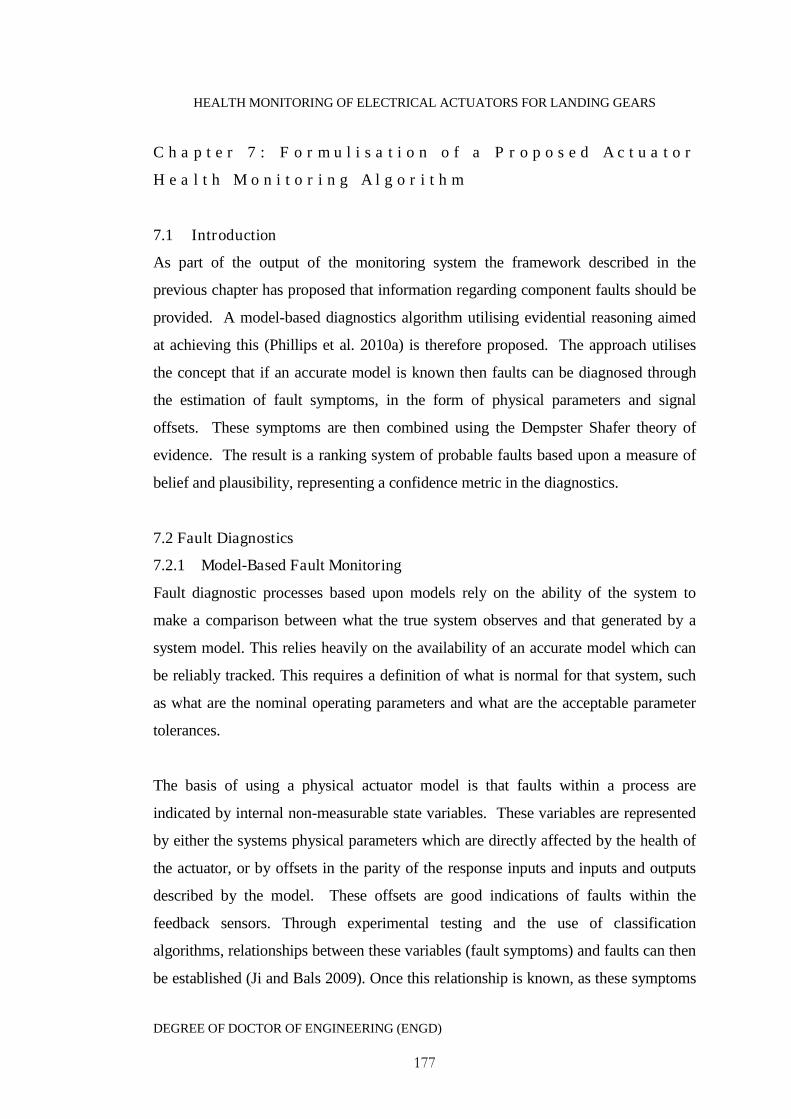
HEALTH MONITORING OF ELECTRICAL ACTUATORS FOR LANDING GEARS
DEGREE OF DOCTOR OF ENGINEERING (ENGD)
177
C h a p t e r 7 : F o r m u l i s a t i o n o f a P r o p o s e d A c t u a t o r
H e a l t h M o n i t o r i n g A l g o r i t h m
7.1 Introduction
As part of the output of the monitoring system the framework described in the
previous chapter has proposed that information regarding component faults should be
provided. A model-based diagnostics algorithm utilising evidential reasoning aimed
at achieving this (Phillips et al. 2010a) is therefore proposed. The approach utilises
the concept that if an accurate model is known then faults can be diagnosed through
the estimation of fault symptoms, in the form of physical parameters and signal
offsets. These symptoms are then combined using the Dempster Shafer theory of
evidence. The result is a ranking system of probable faults based upon a measure of
belief and plausibility, representing a confidence metric in the diagnostics.
7.2 Fault Diagnostics
7.2.1 Model-Based Fault Monitoring
Fault diagnostic processes based upon models rely on the ability of the system to
make a comparison between what the true system observes and that generated by a
system model. This relies heavily on the availability of an accurate model which can
be reliably tracked. This requires a definition of what is normal for that system, such
as what are the nominal operating parameters and what are the acceptable parameter
tolerances.
The basis of using a physical actuator model is that faults within a process are
indicated by internal non-measurable state variables. These variables are represented
by either the systems physical parameters which are directly affected by the health of
the actuator, or by offsets in the parity of the response inputs and inputs and outputs
described by the model. These offsets are good indications of faults within the
feedback sensors. Through experimental testing and the use of classification
algorithms, relationships between these variables (fault symptoms) and faults can then
be established (Ji and Bals 2009). Once this relationship is known, as these symptoms

HEALTH MONITORING OF ELECTRICAL ACTUATORS FOR LANDING GEARS
DEGREE OF DOCTOR OF ENGINEERING (ENGD)
178
are derived, they can be automatically mapped to corresponding fault cases. Potential
fault candidates would then be ranked in order of likelihood of occurrence, severity or
by a measure of believability (Phillips et al 2010b). Figure (7.1) illustrates this
approach.
Figure7.1: Model Based Fault Diagnostics Scheme
Control sensors are an essential part of the overall actuator system and are the core
source of data for the proposed health monitoring system. Therefore sensor fault
detection/diagnosis must also be included in the design. The most appropriate model-
based approach to sensor fault detection is to utilise a set of residuals derived from the
parity between the actuators governing equations.
7.2.2 Formulating Parity Relations
Prior to formulating a set of parity equations two vector sets of parameters must be
specified. The fault to be diagnosed denoted as vector Tnaaa ,, 21A and a
set of the process measurements which are available denoted as the
vector Tkmmm ,, 21M . The fault set A actually includes information
describing sensor failures, actuator failures, external disturbances, degradation of
equipment etc. Following on from the definition of these two vectors a set of parity
relations can be expressed as:

HEALTH MONITORING OF ELECTRICAL ACTUATORS FOR LANDING GEARS
DEGREE OF DOCTOR OF ENGINEERING (ENGD)
179
mknm
jknj
kn
kn
rmmmmaaaac
rmmmmaaaac
rmmmmaaaac
rmmmmaaaac
),,,,,,,,,(
),,,,,,,,,(
),,,,,,,,,(
),,,,,,,,,(
321321
321321
23213212
13213211
RMAC ),( Equation 7.1
These equations are typically a set of nonlinear relations which under nominal
operating conditions the RHS is equal to zero 021 mrrr for
Tsn
sss aaa ,, 21A where the superscript s denotes the nominal steady state
allowing a set of linear algebraic equations too be derived as:
mmnmnimimm
jjnjnijijj
nnii
nnii
rkapapapap
rkapapapap
rkapapapap
rkapapapap
2211
2211
2222222121
1111212111
Or RKAP . Equation 7.2
It should be noticed that from the above set of equations that iji ap , and jk are all
functions of process measurements and the system parameters. Here jip can be
viewed as the sensitivity to the ith fault ( ia ) with respect to the jth parity equation at a
nominal steady state. Mathematically this can be described as:
si
j
jia
cp
Equation 7.3

HEALTH MONITORING OF ELECTRICAL ACTUATORS FOR LANDING GEARS
DEGREE OF DOCTOR OF ENGINEERING (ENGD)
180
Again it must be emphasised that at nominal steady-state conditions the residuals
generated from the parity equations are zero. That is when nominal steady-state
values are substituted for the fault set sii aa and process measurements
sii mm and the equations yields zero residuals:
0)()( sss mkamp Equation 7.4
When a fault occurs isii aaa * , the fault leads to a new set of process
measurements M . However, at this point no knowledge of which possible change
constituting as the fault is known. Substituting sA and M into the parity relations
leading to an inconsistency in the relations:
0RMKAMP )()( * Equation 7.5
For the case where there is a failure of a sensor and ia is a process measurement, then
the explanation is slightly different. The correct process measurement is
imeasij aaa ,* Equation 7.2
Where measia , is the measurement reading and ia represents the sensor bias. Actuator
and sensor faults are not the only source of errors present in such residuals. In order to
achieve robustness in any fault diagnosis provisions must be made for the electing of
satisfactory violations in the parity relations.
7.2.3 Defining Residual Thresholds
Most diagnostic systems based upon model-based techniques define tolerance
thresholds solely for each parity equation. Problems can arise in the diagnostic
resolution with this approach, for example, a fixed threshold may be too large to be
violated by one fault and too small for another. A natural approach would be to define

HEALTH MONITORING OF ELECTRICAL ACTUATORS FOR LANDING GEARS
DEGREE OF DOCTOR OF ENGINEERING (ENGD)
181
thresholds not just for each equation but also for each fault possibility. For example, a
system with m parity equations and n faults to be diagnosed would have nm
tolerances denoted as ji where mj ,2,1( and ),2,1 ni . Therefore a fault of
origin ia would have an upper bound of sia)1( and a lower bound s
ia)1( which
when applied to the jth residual becomes:
0),,,,)1(,,,( 121 Msn
si
si
ssj
Hji aaaaac Equation 7.3
),,,,)1(,,,(0 121 Msn
si
si
ssj
Lji aaaaac Equation 7.4
It should be noted that tolerances for both an upper and lower bound should be
defined but that these do not necessarily have to be the same.
Lji
Hji Equation 7.5
One of the characteristics of start/stop motor driven actuation is that high voltage
spikes can occur during the initial actuator start up and at the stopping phases. The
nature of the actuators varying operation regime and environmental changes mean that
the magnitude of these spikes will not be constant at each actuator cycle. Even though
snubbing systems are designed to limit these voltage spikes some spiking is still likely
to occur. The starting and stopping phases are therefore nonlinear and will be
translated into the residuals. Fixed constant thresholds therefore would immediately
be violated at the start and stop phases of the operation, triggering alarms
unnecessarily. Residuals could be enhanced through effective modelling of these
stages, to stabilise the process of change detection. However, this task can be
simplified by designing thresholds to take into consideration the sensitivity of the
residual with respect to the symptoms creating a threshold which will encompass all
stages of the systems nominal operation. This is demonstrated in Figure (7.2).
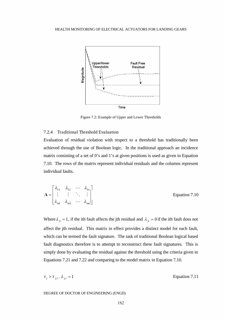
HEALTH MONITORING OF ELECTRICAL ACTUATORS FOR LANDING GEARS
DEGREE OF DOCTOR OF ENGINEERING (ENGD)
182
Figure 7.2: Example of Upper and Lower Thresholds
7.2.4 Traditional Threshold Evaluation
Evaluation of residual violation with respect to a threshold has traditionally been
achieved through the use of Boolean logic. In the traditional approach an incidence
matrix consisting of a set of 0’s and 1’s at given positions is used as given in Equation
7.10. The rows of the matrix represent individual residuals and the columns represent
individual faults.
mnmm
n
21
11211
Λ Equation 7.10
Where 1ji , if the ith fault affects the jth residual and 0ji if the ith fault does not
affect the jth residual. This matrix in effect provides a distinct model for each fault,
which can be termed the fault signature. The task of traditional Boolean logical based
fault diagnostics therefore is to attempt to reconstruct these fault signatures. This is
simply done by evaluating the residual against the threshold using the criteria given in
Equations 7.21 and 7.22 and comparing to the model matrix in Equation 7.10.
ijjr , , 1, ij Equation 7.11

HEALTH MONITORING OF ELECTRICAL ACTUATORS FOR LANDING GEARS
DEGREE OF DOCTOR OF ENGINEERING (ENGD)
183
ijjr , , 0, ij Equation 7.12
Thus, under the ideal circumstances the signature of a fault should be identical to the
respective column of the model matrix. This implies that for each fault/failure to be
detectable, no column of the incidence matrix should contain only zero elements, and
for each signature to be unique all of the columns must be different. There are three
different types of incidence matrix as illustrated in Figure (7.4).
1011
0111
1101
1011
0111
1110
1101
1011
0111
(a) Not isolable (b) Deterministically isolable (c) Statistically isolable
Figure 7.4: The Various Forms of a Fault Incidence
Matrix
The first example is non-isolable, which means that there are multiple identical
columns, making reliable fault diagnosis based on this approach impossible. The
second is known as deterministically isolable where all of the respective columns are
different allowing for effective fault diagnosis, providing that there is no misfiring of
the rules in Equations 7.11 and 7.12. For example, a medium sized fault may occur
and cause the firing of a matrix element whilst others that should fire are not. The
resulting signature is a degraded version for the respective column (with some 1’s
replaced by 0’s). This partial firing therefore leads to a mis-isolation of faults. There
is however a way in which this can be avoided to obtain a statistically isolable
incidence matrix. The incidence matrix must be constructed in such a fashion that no
column can be obtained from any other column through degradation. These structures
take a column canonical form, where each column has the same number of zeros in a
different pattern.
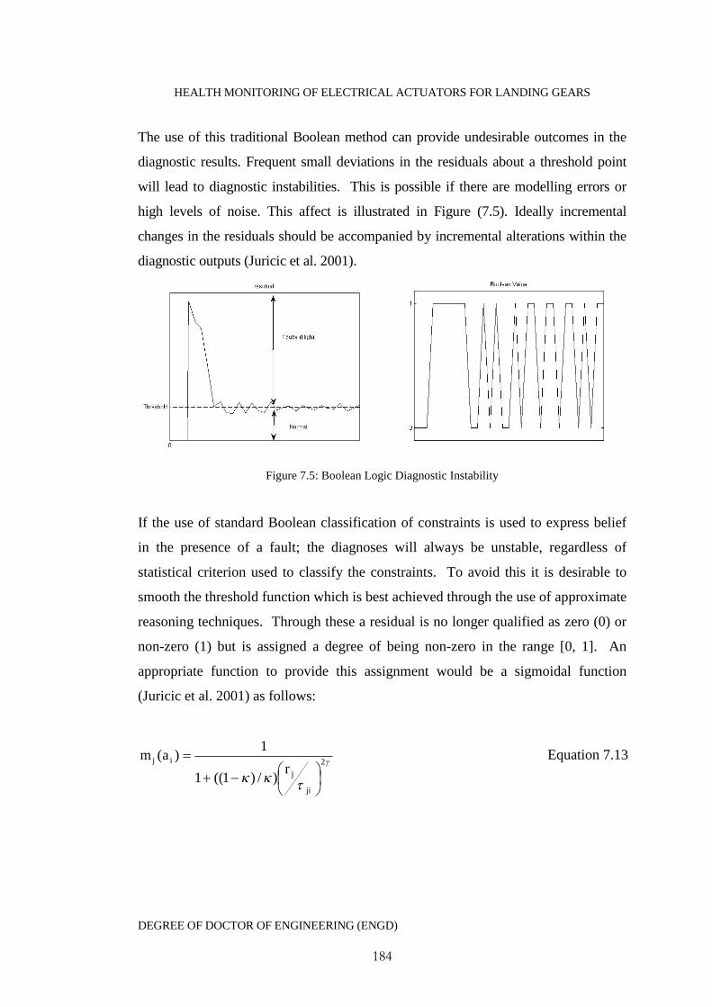
HEALTH MONITORING OF ELECTRICAL ACTUATORS FOR LANDING GEARS
DEGREE OF DOCTOR OF ENGINEERING (ENGD)
184
The use of this traditional Boolean method can provide undesirable outcomes in the
diagnostic results. Frequent small deviations in the residuals about a threshold point
will lead to diagnostic instabilities. This is possible if there are modelling errors or
high levels of noise. This affect is illustrated in Figure (7.5). Ideally incremental
changes in the residuals should be accompanied by incremental alterations within the
diagnostic outputs (Juricic et al. 2001).
Figure 7.5: Boolean Logic Diagnostic Instability
If the use of standard Boolean classification of constraints is used to express belief
in the presence of a fault; the diagnoses will always be unstable, regardless of
statistical criterion used to classify the constraints. To avoid this it is desirable to
smooth the threshold function which is best achieved through the use of approximate
reasoning techniques. Through these a residual is no longer qualified as zero (0) or
non-zero (1) but is assigned a degree of being non-zero in the range [0, 1]. An
appropriate function to provide this assignment would be a sigmoidal function
(Juricic et al. 2001) as follows:
2
)/)1((1
1)(
ji
j
ijr
am Equation 7.13
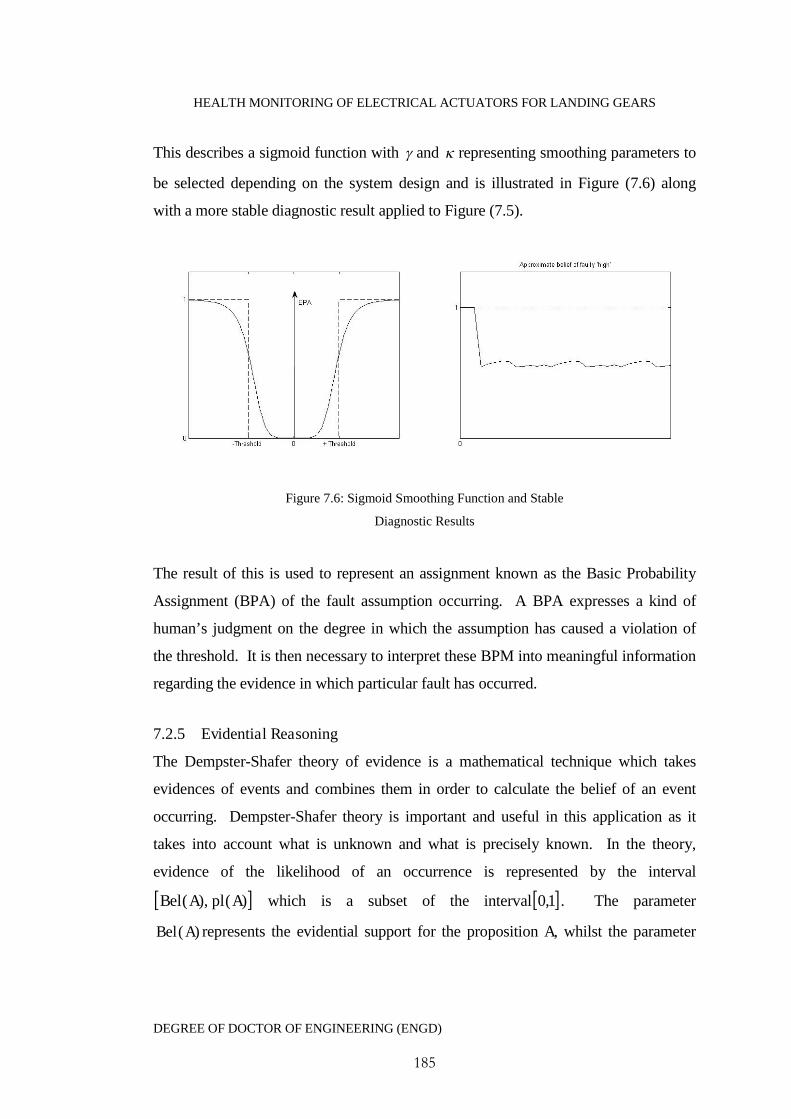
HEALTH MONITORING OF ELECTRICAL ACTUATORS FOR LANDING GEARS
DEGREE OF DOCTOR OF ENGINEERING (ENGD)
185
This describes a sigmoid function with and representing smoothing parameters to
be selected depending on the system design and is illustrated in Figure (7.6) along
with a more stable diagnostic result applied to Figure (7.5).
Figure 7.6: Sigmoid Smoothing Function and Stable
Diagnostic Results
The result of this is used to represent an assignment known as the Basic Probability
Assignment (BPA) of the fault assumption occurring. A BPA expresses a kind of
human’s judgment on the degree in which the assumption has caused a violation of
the threshold. It is then necessary to interpret these BPM into meaningful information
regarding the evidence in which particular fault has occurred.
7.2.5 Evidential Reasoning
The Dempster-Shafer theory of evidence is a mathematical technique which takes
evidences of events and combines them in order to calculate the belief of an event
occurring. Dempster-Shafer theory is important and useful in this application as it
takes into account what is unknown and what is precisely known. In the theory,
evidence of the likelihood of an occurrence is represented by the interval
)(),( AplABel which is a subset of the interval 1,0 . The parameter
)(ABel represents the evidential support for the proposition A, whilst the parameter
HEALTH MONITORING OF ELECTRICAL ACTUATORS FOR LANDING GEARS
DEGREE OF DOCTOR OF ENGINEERING (ENGD)
186
)(Apl represents the plausibility of the proposition. An interpretation of this is the
probability of A is bounded by defined as )(ABel and )(Apl .
)()()( AplAPABel Equation 7.14
The uncertainty in A is given by
)()()( ABelAplAu Equation 7.15
In the Dempster Shafer theory hypotheses are represented by a subset of all relevant
hypotheses. This is known as the frame of discernment . In the context of fault
diagnostics the frame of discernment will contain all faults and the state of normal
operation. It should be noted that the state of normal operation is equal to the negation
of all other faults.
The evidential intervals )(),( AplABel are derived through the manipulation of the
BPA which distributes a unit of belief over the set of hypotheses. In effect the BPA
of A represented by )(Am is the portion of belief assigned to the hypothesis A , where
A is any subset of . If it is not possible to assign a portion of belief to any particular
subset of based upon the available evidence then this residual belief is assigned
directly to . This has the effect of introducing uncertainty into the system. The
formulation of the theory of evidence is as follows.
The belief in the hypothesis A is the sum of all of the BPA assigned to A and all of
the subsets of A :
)()( iAmABel , AAi Equation 7.16
The plausibility of the proposition is given by:

HEALTH MONITORING OF ELECTRICAL ACTUATORS FOR LANDING GEARS
DEGREE OF DOCTOR OF ENGINEERING (ENGD)
187
)(1)( ii BmApl , 'ABi Equation 7.17
The set 'A is the set with all of the elements of A removed.
For a given application there will be several sources of information which will
contribute various degrees of belief to a given proposition under a common frame of
discernment. In the current model based fault diagnosis approach this is highlighted
by considering that multiple residuals are sensitive to the common faults. Dempster
Shafer provides an efficient rule of combination to deal with this. This area of the
reasoning process is discussed in later sections.
7.2.6 Introducing Residual Uncertainty
As with all systems a certain degree of uncertainty will be inherently visible in the
residuals, due to noise, modelling or measurement errors, even under fault free
conditions. The assignment of appropriate belief masses therefore must take into
consideration this uncertainty, and Equation 7.13 is modified as follows:
2
)/)1((1
11)(
ji
j
jiijr
am Equation 7.18
Here the term ji1 has permitted the introduction of residual errors into the belief
function when the reliability of the information derived from the constraint is less than
unity. The evidential intervals based upon Equation 7.14 are now described by
Equations 7.19 and 7.20. Where 0ji ,
ji , ji represents the conditions of no threshold,
upper threshold and lower threshold breach respectively, with regards to the jth
residual and ith fault.
iiiji mm , , iij ,0, iiiij mm 1,10 for 0jr Equation 7.19
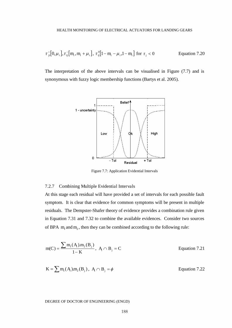
HEALTH MONITORING OF ELECTRICAL ACTUATORS FOR LANDING GEARS
DEGREE OF DOCTOR OF ENGINEERING (ENGD)
188
iji ,0 , iiiij mm , , iiiij mm 1,10 for 0jr Equation 7.20
The interpretation of the above intervals can be visualised in Figure (7.7) and is
synonymous with fuzzy logic membership functions (Bartys et al. 2005).
Figure 7.7: Application Evidential Intervals
7.2.7 Combining Multiple Evidential Intervals
At this stage each residual will have provided a set of intervals for each possible fault
symptom. It is clear that evidence for common symptoms will be present in multiple
residuals. The Dempster-Shafer theory of evidence provides a combination rule given
in Equation 7.31 and 7.32 to combine the available evidences. Consider two sources
of BPA 1m and 2m , then they can be combined according to the following rule:
K
BmAmCm
ji
1
)(.)()(
21, CBA ji Equation 7.21
)().( 21 ji BmAmK , ji BA Equation 7.22

HEALTH MONITORING OF ELECTRICAL ACTUATORS FOR LANDING GEARS
DEGREE OF DOCTOR OF ENGINEERING (ENGD)
189
The factor )1( K is a normalization factor that keeps the total belief equal to unity.
The adjustment is necessary by the presence of propositions in 1m and 2m whose
intersection is empty, resulting in the donation of a portion of belief to the empty set
. In terms of decision making, consider a fault symptom Ff , the evidential interval
)(),( FF fplfBel represents the truth of the proposition indicated by the following
examples (Kramer 1987).
]1,0[Ff → No information exists regarding Ff
]0,0[Ff → Ff is false
]1,1[Ff → Ff is true
]1,3.0[Ff → The evidence partially supports Ff
]7.0,0[Ff → The evidence partially supports the negation of Ff
]7.0,3.0[Ff → The evidence partially supports both the presence and negation of
Ff .The probability of Ff is between 0.3 and 0.7 with uncertainty
0.4.
7.2.8 Combining Rules for Comprehensive Diagnostics
After the belief intervals for the propositions have been found and the uncertainties in
all propositions in the frame of discernment then the diagnostic results can be
determined through the application of a few simple decision rules:
Rule 1: )(max)( ii
a fBelfBel
Rule 2: 0,)()(,)()( mfBelfBelfBel aia
Rule 3: 0,)( m

HEALTH MONITORING OF ELECTRICAL ACTUATORS FOR LANDING GEARS
DEGREE OF DOCTOR OF ENGINEERING (ENGD)
190
Rule 1 indicates that the result of the diagnostics must be the proposition af with
the biggest proportion of belief. Rule 2 indicates that the possibility of the
diagnostic result must be bigger than all o the propositions by an amount . Rule 3
indicates that the uncertainty in the evidence for a proposition must be less than a
value . The values and are too be chosen according to the practical
application. If the diagnostic result af cannot be ascertained then a new frame of
discernment should be constructed or more evidence bodies should be added to the
computation (Yang and Wu 2007).
7.3 Advantages of the Proposed Methodology
The model-based diagnostics approach has the following advantages:
Requires no additional sensing equipment acting only on dynamic data already
available as part of the actuator control.
The actuator does not require complicated modelling, making a model-based
diagnostic approach ideal.
The combination of data into parity residuals reduces the number of signals for
analysis.
Faults are traced back to meaningful physical parameters, which can often be
more easily understood than many of the subjective features available from
alternative diagnostic techniques.
The approach allows the introduction of uncertainty into the system which
relates to measurement or modelling errors.

HEALTH MONITORING OF ELECTRICAL ACTUATORS FOR LANDING GEARS
DEGREE OF DOCTOR OF ENGINEERING (ENGD)
191
The final output of the approach provides the user with information on the
extent to which a fault has occurred coupled with how believable the evidence
is. The difference between the two provides a measure of uncertainty useful in
decision making.
7.4 Conclusions
The second part of the health monitoring algorithm forms the basis of a model based
fault diagnostics process. This approach requires the use of an accurate system
model and combining the actuators dynamic process data in the form of a set of
parity equations which are used to form a set of diagnostic residuals, sensitive to
fault occurrences. The residuals are naturally designed to remain close to zero in
fault-free conditions. In the presence of a fault the residuals will deviate either
positively or negatively.
Unlike traditional parity equation based fault diagnostics, the residuals are not
assessed through the use of ‘one threshold per residual’. Each residual will contain
information regarding multiple fault symptoms. An untraditional approach is therefore
proposed utilising multiple thresholds for each residual each representing an
individual fault. The nature of the actuators operation means that there are several
nonlinear regions in the dynamic al data, most notably at the start and stopping phases.
Fixed static thresholds cannot be used in this case as there will most likely be an
instant threshold violation in these regions. This is overcome by designing thresholds
by utilising the model equations sensitivities to faults. This creates a threshold which
is not fixed but follows the dynamic profiles of the data.
Threshold violations are traditionally detected through Boolean Logic. The
shortcomings of which is that in the presence of noise and modelling errors Boolean
logic based diagnostics suffer from instability. Also there is no indication to the level
of severity in the threshold violation. This is overcome by utilising approximate
reasoning. This approach provides a measure on the extent to which a threshold has
been breached allowing estimation to the magnitude of the fault occurrence. With this
HEALTH MONITORING OF ELECTRICAL ACTUATORS FOR LANDING GEARS
DEGREE OF DOCTOR OF ENGINEERING (ENGD)
192
approach incremental changes in the residuals about a threshold will result in
incremental changes to the diagnostic results.
The Dempster Shafer theory of evidence is used to produce intervals based on
symptoms categorised as High, Low or Okay. The interval provides a measure of
belief in the symptom occurring and a measure of how plausible the reasoning is. The
probability of the symptom is bounded by the belief and plausibility and the difference
magnitude of the space between the bounds represents the uncertainty in the
diagnostics. Each residual includes information regarding multiple symptoms, many
of which will be common throughout the set of residuals. Dempster Shafers theory of
evidence provides a rule of combination which is utilised to combine these common
residuals, leaving an individual interval for the values of High, Low, and Okay for
each symptom. These intervals are then compared to a set of three diagnostic
performance rules before a diagnostic certainty is made.
7.5 References
Ji, Y., Bals, J., (2009), ‘Application of Model Detection Techniques to Health
Monitoring for the Electrical Network of More Electric Aircraft’, Proceedings of the
World Congress on Engineering and Computer Science, San Francisco, USA.
Juricic, D., O. Moseler, and A. Rakar, Model-based condition monitoring of an
actuator system driven by a brushless DC motor. Control Engineering Practice, 2001.
9(5): p. 545-554.
Kramer, M., (1987), 'Malfunction diagnosis using quantitative models with non-
boolean reasoning in expert systems'. AIChE Journal, Vol. 33, No. 1, pp. 130-140
Phillips, P., Diston, D., Payne, J., Pandya, S. (2010a), 'Evidential Reasoning Applied
to Model-Based Diagnostics in Landing gear Actuators' in Machine Failure and
Prevention Technology Conference. AL, USA.

HEALTH MONITORING OF ELECTRICAL ACTUATORS FOR LANDING GEARS
DEGREE OF DOCTOR OF ENGINEERING (ENGD)
193
Phillip, P., Diston, D., (2010b) ‘An Intelligent Health Monitoring Framework for a
Motor-Driven Actuator’, Proceedings for The 7th International Conference on
Condition Monitoring and Machine Failure Technologies, Edinburgh, UK
HEALTH MONITORING OF ELECTRICAL ACTUATORS FOR LANDING GEARS
DEGREE OF DOCTOR OF ENGINEERING (ENGD)
194
C h a p t e r 8 : S y s t e m M o d e l l i n g , S i m u l a t i o n a n dD i a g n o s t i c s D e m o n s t r a t i o n
8.1 Introduction
Chapter seven provided the formulisation of a proposed model-based approach to
actuator fault diagnostics. This chapter seeks to justify the applicability of this
algorithm and demonstrate its usage and potential effectiveness. The landing gear
retraction actuators focused on in this research are currently still under development
and have not yet been put into production for operational usage or testing. A
consequence of which is that there does not exist any operational data on the actuator
system whilst a fault is developing. The economic costs associated with the actuator
development would also prevent artificial faults being introduced. This inevitably
creates challenges in the development of a health monitoring system. In the absence
of a landing gear experimental testing rig this demonstration must be sought through
actuator modelling and simulation.
In order to keep the demonstration applicable to the specific landing gear application,
a representative model of the actuator system has been developed and its performance
simulated within the MATLAB/SIMULINK environment. Though the use of expert
knowledge on how faults manifest themselves within changes to model parameters,
the use of a simulated model can be used to generate representative data relative to
faulty behaviour.
Based upon the actuator model equations a set of nominal fault sensitive residuals are
derived. Faults are simulated through a range of physical parameter changes and
signal offsets based in accordance with information obtained from published
literature. Threshold levels are identified based upon the effects model changes have
upon the actuator cycle time, with upper and lower boundary cycle times in
accordance with the actuator developer’s requirements. The simulation is run for the
case of changes to the frictional constant and illustrates how combinations of
additional evidence can aid in clarifying an uncertain diagnostic result.
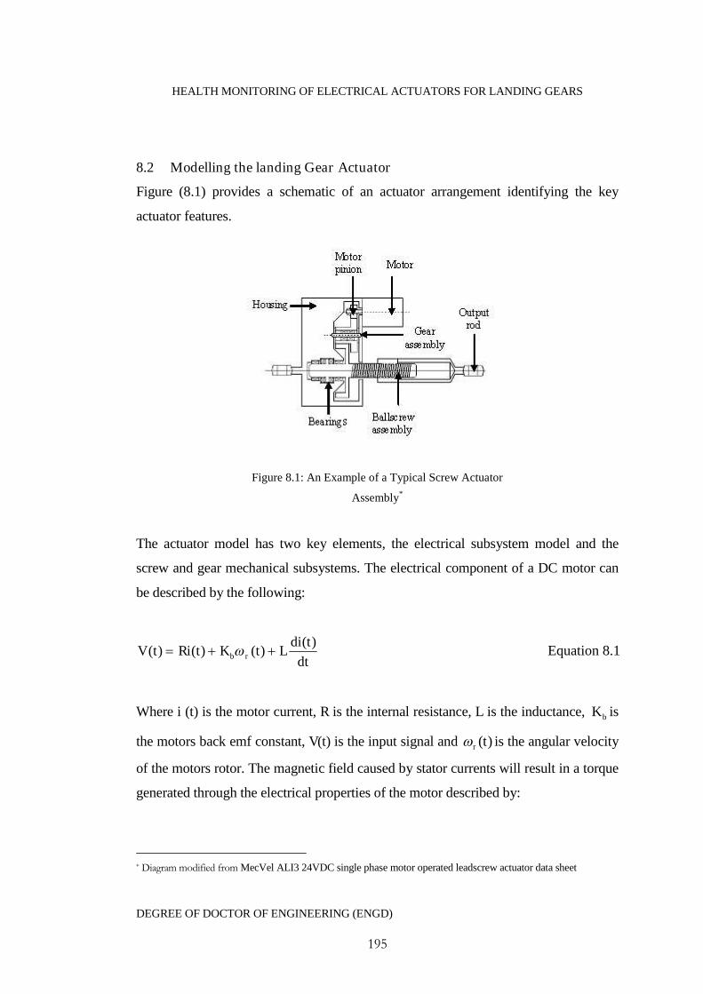
HEALTH MONITORING OF ELECTRICAL ACTUATORS FOR LANDING GEARS
DEGREE OF DOCTOR OF ENGINEERING (ENGD)
195
8.2 Modelling the landing Gear Actuator
Figure (8.1) provides a schematic of an actuator arrangement identifying the key
actuator features.
Figure 8.1: An Example of a Typical Screw Actuator
Assembly*
The actuator model has two key elements, the electrical subsystem model and the
screw and gear mechanical subsystems. The electrical component of a DC motor can
be described by the following:
dt
tdiLtKtRitV rb
)()()()( Equation 8.1
Where i (t) is the motor current, R is the internal resistance, L is the inductance, bK is
the motors back emf constant, V(t) is the input signal and )(tr is the angular velocity
of the motors rotor. The magnetic field caused by stator currents will result in a torque
generated through the electrical properties of the motor described by:
* Diagram modified from MecVel ALI3 24VDC single phase motor operated leadscrew actuator data sheet

HEALTH MONITORING OF ELECTRICAL ACTUATORS FOR LANDING GEARS
DEGREE OF DOCTOR OF ENGINEERING (ENGD)
196
iTelec tiKt ).()( Equation 8.2
The torque constant TK in an ideal motor will tend to be bT KK . The term i
represents the efficiency of the motors current controller. Through the use of
conservation of momentum the torque will be described as:
)()()()( tttt lossesloadelec Equation 8.3
The torque load , results from work being done against the systems mechanical load
and losses through friction (coulomb and viscous) within the system. Equation 8.3 is
therefore described as:
)()()()( tBttiKtJ rloadbr Equation 8.4
Where J is the inertia of the system which is concentrated at the motor and B is given
as the friction constant.
For a rigid screw without backlash, the compatibility condition between the rotational
position of the gear )(tr and the rotational position of the ballscrew )(tbs is given
by:
rr t )( Equation 8.5
)(1
)( tN
t bsr Equation 8.6
Where N is the gear ratio and the linear distance moved by the nut in one complete
revolution of the screw is the lead l , which can be described as the effective radius of
the screw as:

HEALTH MONITORING OF ELECTRICAL ACTUATORS FOR LANDING GEARS
DEGREE OF DOCTOR OF ENGINEERING (ENGD)
197
2
lR Equation 8.7
The total linear distance moved in one actuator cycle is therefore described as:
)(.2
.)(.)( t
N
ltRtx rbs
Equation 8.9
The load load can be calculated through measurement of the actuator load F as:
screwgear
loadN
FRt
..
.)( Equation 8.10
8.3 Simulation
8.3.1 Overview of the Actuator SIMULINK Model
The model of the actuator was designed within the SIMULINK environment, with
MATLAB program files containing the SIMULINK model parameters. The
simulation of the actuator was achieved by running a MATLAB run file which
requests the user select the following options:
1) Initial start position of the actuator (i.e. extended or retracted)
2) Actuator load case
3) Damped or un-damped performance
The SIMULINK model for the main actuator model (Figure 8.2) is automatically run
for one actuator cycle and the user is requested to select the performance response
data to save as a data file.
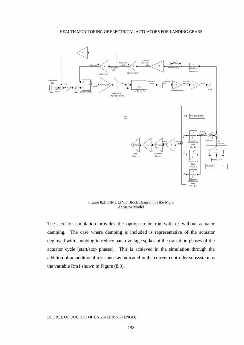
HEALTH MONITORING OF ELECTRICAL ACTUATORS FOR LANDING GEARS
DEGREE OF DOCTOR OF ENGINEERING (ENGD)
198
max demand
10V
xmax
Kt
torque constant
at 20 deg C (Nm/A)
1/N 1/effscrew
rollerscrew
efficiency
N
motor:rollerscrew
1000
m to mm
init_pos_m
1/effgear
gear
efficiency
Kb
emf constant
eff_curr_cont
s
1.0e-03s+1
differentiator
ViLim
>=
Step
R
R
1
2
*3,
1
J.s+B
Load Transfer Fcn
Load Look-Up
Table
250knt_1.3g
Load Look-Up
Table
170knt_1.1g
Load Look-Up
Table
0knt_1g
K1V
1
s
H2
-K-
Vb
Vi
im
Current Controller
damped_mode
load_case_selector
0
1/R
1/N
1/(motor:rollerscrew)
back emf (V)
torque
current (A)
motor angle
(rad)
rollerscrew
angle (rad) xm (m)
xm (mm)
(Position)
Act_Load
(N)
torque
(N/m)
torque
(N/m)
initial
position (m)
actuator rate (m/s)
rollerscrew
rotation speed
(rad/s)
motor_speed
(rad/s)
motor_speed
(rad/s)
motor speed
(rad/s)
input
v oltage
Rate
Figure 8.2: SIMULINK Block Diagram of the MainActuator Model
The actuator simulation provides the option to be run with or without actuator
damping. The case where damping is included is representative of the actuator
deployed with snubbing to reduce harsh voltage spikes at the transition phases of the
actuator cycle (start/stop phases). This is achieved in the simulation through the
addition of an additional resistance as indicated in the current controller subsystem as
the variable Rm1 shown in Figure (8.3).
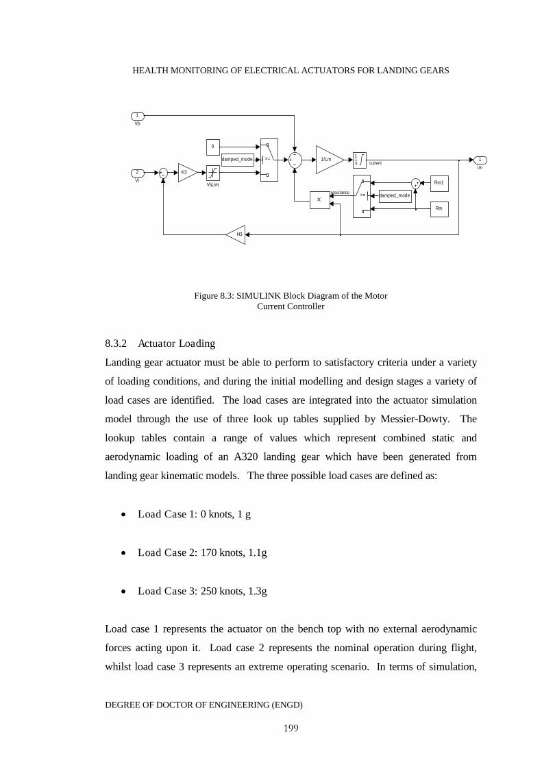
HEALTH MONITORING OF ELECTRICAL ACTUATORS FOR LANDING GEARS
DEGREE OF DOCTOR OF ENGINEERING (ENGD)
199
1
im
VsLim
>=
>=
Rm1
Rm
K3
1
s
H3
damped_mode
damped_mode
0
1/Lm
2
Vi
1
Vb
current
resistance
Figure 8.3: SIMULINK Block Diagram of the MotorCurrent Controller
8.3.2 Actuator Loading
Landing gear actuator must be able to perform to satisfactory criteria under a variety
of loading conditions, and during the initial modelling and design stages a variety of
load cases are identified. The load cases are integrated into the actuator simulation
model through the use of three look up tables supplied by Messier-Dowty. The
lookup tables contain a range of values which represent combined static and
aerodynamic loading of an A320 landing gear which have been generated from
landing gear kinematic models. The three possible load cases are defined as:
Load Case 1: 0 knots, 1 g
Load Case 2: 170 knots, 1.1g
Load Case 3: 250 knots, 1.3g
Load case 1 represents the actuator on the bench top with no external aerodynamic
forces acting upon it. Load case 2 represents the nominal operation during flight,
whilst load case 3 represents an extreme operating scenario. In terms of simulation,
HEALTH MONITORING OF ELECTRICAL ACTUATORS FOR LANDING GEARS
DEGREE OF DOCTOR OF ENGINEERING (ENGD)
200
the lookup tables are used to provide the correct loading torque for feedback into the
electrical motor model. This is achieved by taking the measured actuator stroke
length, at a given time interval, and then interpolating the data provided in the look up
table to obtain the correct loading value for the actuator at that current position.
The use of these validated loading lookup tables reduces the need for modelling and
simulation of the landing gear kinematics as part of this research, reducing the
complexity of the model for simulation of the health monitoring algorithm. This
loading is then converted into the motor loading torque using Equation 8.10.
When the landing gears are not deployed, the actuator is at a fully extended stroke
position. As the gears are then extended through to deployment, the actuator
essentially pulls against a lever arm acting about a pivot lowering the gears.
Conversely, when the landing gear is retracted the actuator extends and hence pushes
against the lever arm.
When the landing gears are being extended, the applied loading drives the landing
gear motion, pushing the landing gears down, with higher loads resulting in faster
cycle times. In the case of a retraction cycle, then the applied load works against the
landing gears meaning that higher loads will result in slower cycle times.
8.3.3 Actuator Performance Simulation
Table 8.1 provides the nominal actuator physical data parameters used within the
simulation model
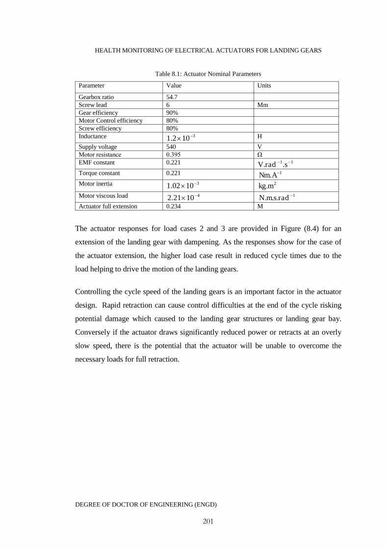
HEALTH MONITORING OF ELECTRICAL ACTUATORS FOR LANDING GEARS
DEGREE OF DOCTOR OF ENGINEERING (ENGD)
201
Table 8.1: Actuator Nominal Parameters
Parameter Value Units
Gearbox ratio 54.7Screw lead 6 MmGear efficiency 90%Motor Control efficiency 80%Screw efficiency 80%Inductance 3102.1 H
Supply voltage 540 VMotor resistance 0.395 Ω EMF constant 0.221 11.. sradVTorque constant 0.221 1. ANmMotor inertia 31002.1 2.mkgMotor viscous load 41021.2 1... radsmNActuator full extension 0.234 M
The actuator responses for load cases 2 and 3 are provided in Figure (8.4) for an
extension of the landing gear with dampening. As the responses show for the case of
the actuator extension, the higher load case result in reduced cycle times due to the
load helping to drive the motion of the landing gears.
Controlling the cycle speed of the landing gears is an important factor in the actuator
design. Rapid retraction can cause control difficulties at the end of the cycle risking
potential damage which caused to the landing gear structures or landing gear bay.
Conversely if the actuator draws significantly reduced power or retracts at an overly
slow speed, there is the potential that the actuator will be unable to overcome the
necessary loads for full retraction.
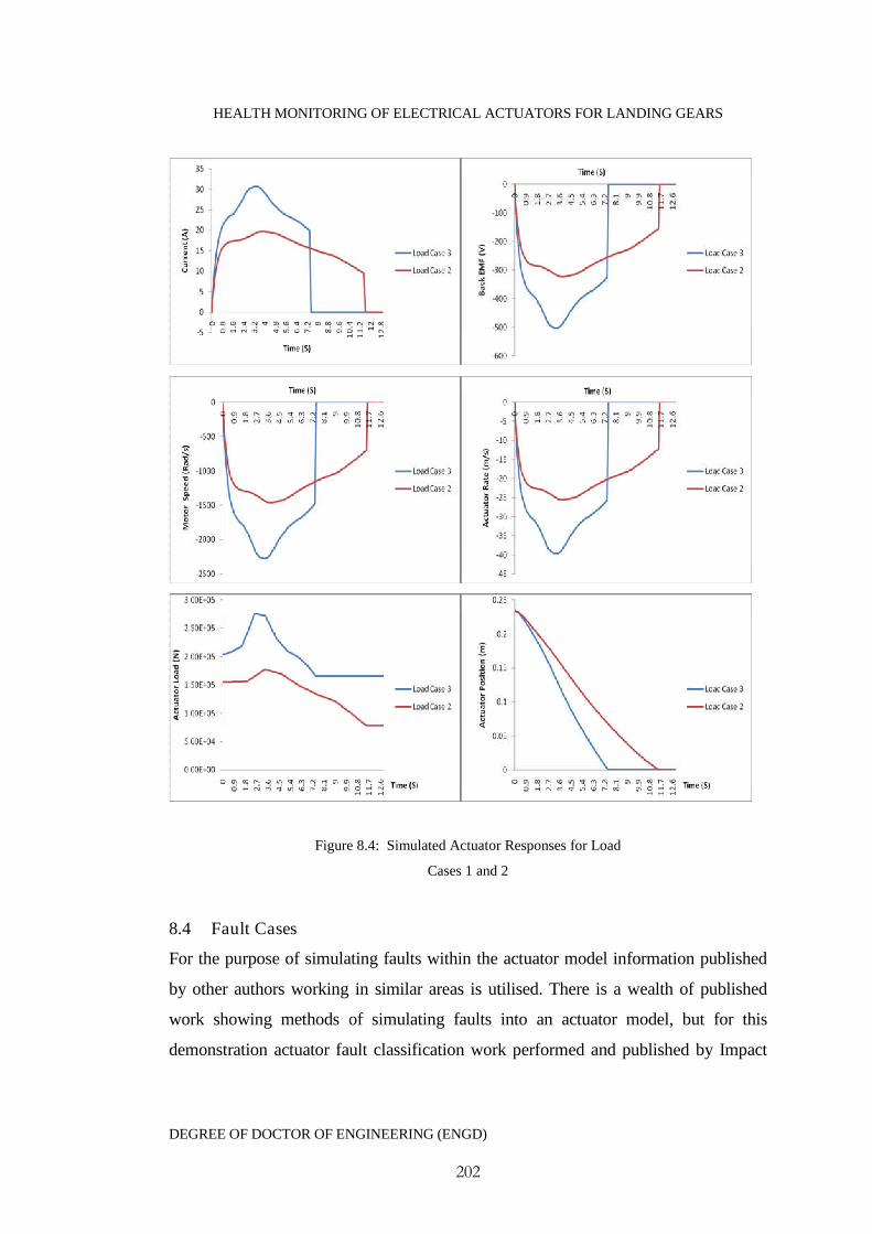
HEALTH MONITORING OF ELECTRICAL ACTUATORS FOR LANDING GEARS
DEGREE OF DOCTOR OF ENGINEERING (ENGD)
202
Figure 8.4: Simulated Actuator Responses for Load
Cases 1 and 2
8.4 Fault Cases
For the purpose of simulating faults within the actuator model information published
by other authors working in similar areas is utilised. There is a wealth of published
work showing methods of simulating faults into an actuator model, but for this
demonstration actuator fault classification work performed and published by Impact

HEALTH MONITORING OF ELECTRICAL ACTUATORS FOR LANDING GEARS
DEGREE OF DOCTOR OF ENGINEERING (ENGD)
203
Technologies, LLC has been used. Byington and Stoetling (2004) identify after
substantial experimental testing four key parameters of interest for fault diagnostics of
electrical actuators. Examples of these are identified as frictional constants, local gear
stiffness, torque constant and motor temperature which can all be matched to the
following potential faults.
Gear Slippage
Decrease in local gear stiffness
Small increases in frictional damping coefficient
Bearing Seizure
Large increases in frictional coefficient
Small increases in motor temp
Motor Failure
Decreases in torque constant
Large increases in motor temp
It has also been acknowledged that simulation of sensor faults can be achieved
through the introduction of a positive or negative bias within a particular signal of
interest (Byington et al. 2003). In the case of this work the following faults will be
considered:
Fault 1 = Changes in the torque constant
Fault 2 = Changes in the motor resistance
Fault 3 = Changes in the frictional coefficient
Fault 4 = Bias in the speed sensor signal
Fault 5 = Bias in the current sensor signal
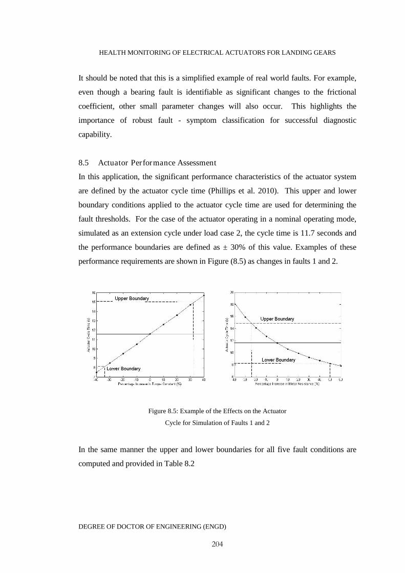
HEALTH MONITORING OF ELECTRICAL ACTUATORS FOR LANDING GEARS
DEGREE OF DOCTOR OF ENGINEERING (ENGD)
204
It should be noted that this is a simplified example of real world faults. For example,
even though a bearing fault is identifiable as significant changes to the frictional
coefficient, other small parameter changes will also occur. This highlights the
importance of robust fault - symptom classification for successful diagnostic
capability.
8.5 Actuator Performance Assessment
In this application, the significant performance characteristics of the actuator system
are defined by the actuator cycle time (Phillips et al. 2010). This upper and lower
boundary conditions applied to the actuator cycle time are used for determining the
fault thresholds. For the case of the actuator operating in a nominal operating mode,
simulated as an extension cycle under load case 2, the cycle time is 11.7 seconds and
the performance boundaries are defined as ± 30% of this value. Examples of these
performance requirements are shown in Figure (8.5) as changes in faults 1 and 2.
Figure 8.5: Example of the Effects on the Actuator
Cycle for Simulation of Faults 1 and 2
In the same manner the upper and lower boundaries for all five fault conditions are
computed and provided in Table 8.2
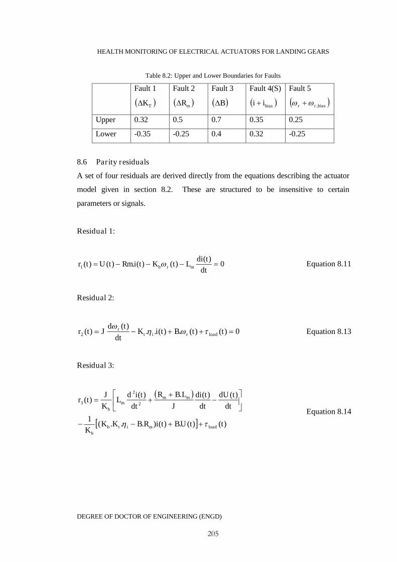
HEALTH MONITORING OF ELECTRICAL ACTUATORS FOR LANDING GEARS
DEGREE OF DOCTOR OF ENGINEERING (ENGD)
205
Table 8.2: Upper and Lower Boundaries for Faults
Fault 1
TK
Fault 2
mR
Fault 3
B
Fault 4(S)
biasii
Fault 5
biasrr ,
Upper 0.32 0.5 0.7 0.35 0.25
Lower -0.35 -0.25 0.4 0.32 -0.25
8.6 Parity residuals
A set of four residuals are derived directly from the equations describing the actuator
model given in section 8.2. These are structured to be insensitive to certain
parameters or signals.
Residual 1:
0)(
)()(.)()(1 dt
tdiLtKtiRmtUtr mrb Equation 8.11
Residual 2:
0)()(.)(..)(
)(2 ttBtiKdt
tdJtr loadrit
r
Equation 8.13
Residual 3:
)()(.)()...(1
)()(.)()(
2
2
3
ttUBtiRBKKK
dt
tdU
dt
tdi
J
LBR
dt
tidL
K
Jtr
loadmitb
b
mmm
b
Equation 8.14

HEALTH MONITORING OF ELECTRICAL ACTUATORS FOR LANDING GEARS
DEGREE OF DOCTOR OF ENGINEERING (ENGD)
206
Residual 4
)()(.
)(..)(..)(
)(4
ttUR
K
tBR
K
dt
tdi
R
LK
dt
tdJtr
load
m
it
r
m
it
m
mitr
Equation 8.15
In the case of the residuals derived here the following applies:
Residual 1r is independent of the signals load and x
Residual 2r is independent of the signals V and x
Residual 3r is independent of the signals load , x , V and r
Residual 4r is independent of the signals V and x
8.6.1 Nominal Test
Figure (8.6) shows the residual responses under nominal simulation conditions. Even
though the residuals have been designed to reduce to zero in fault free conditions,
there is still some deviation, particularly evident in residuals 2 and 3. The cause of
this can be attributed to the residuals dependency on second order differentials, which
have exaggerated the high order dynamics. The mean of this deviation can be taken as
the error within the residual as described by Equation 7.28.
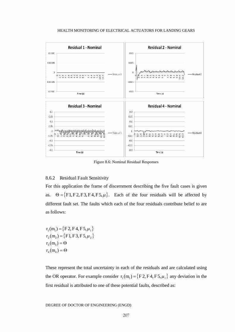
HEALTH MONITORING OF ELECTRICAL ACTUATORS FOR LANDING GEARS
DEGREE OF DOCTOR OF ENGINEERING (ENGD)
207
Figure 8.6: Nominal Residual Responses
8.6.2 Residual Fault Sensitivity
For this application the frame of discernment describing the five fault cases is given
as. ,5,4,3,2,1 FFFFF . Each of the four residuals will be affected by
different fault set. The faults which each of the four residuals contribute belief to are
as follows:
)(
)(
,5,3,1)(
,5,4,2)(
44
33
222
111
mr
mr
FFFmr
FFFmr
These represent the total uncertainty in each of the residuals and are calculated using
the OR operator. For example consider 111 ,5,4,2)( FFFmr any deviation in the
first residual is attributed to one of these potential faults, described as:
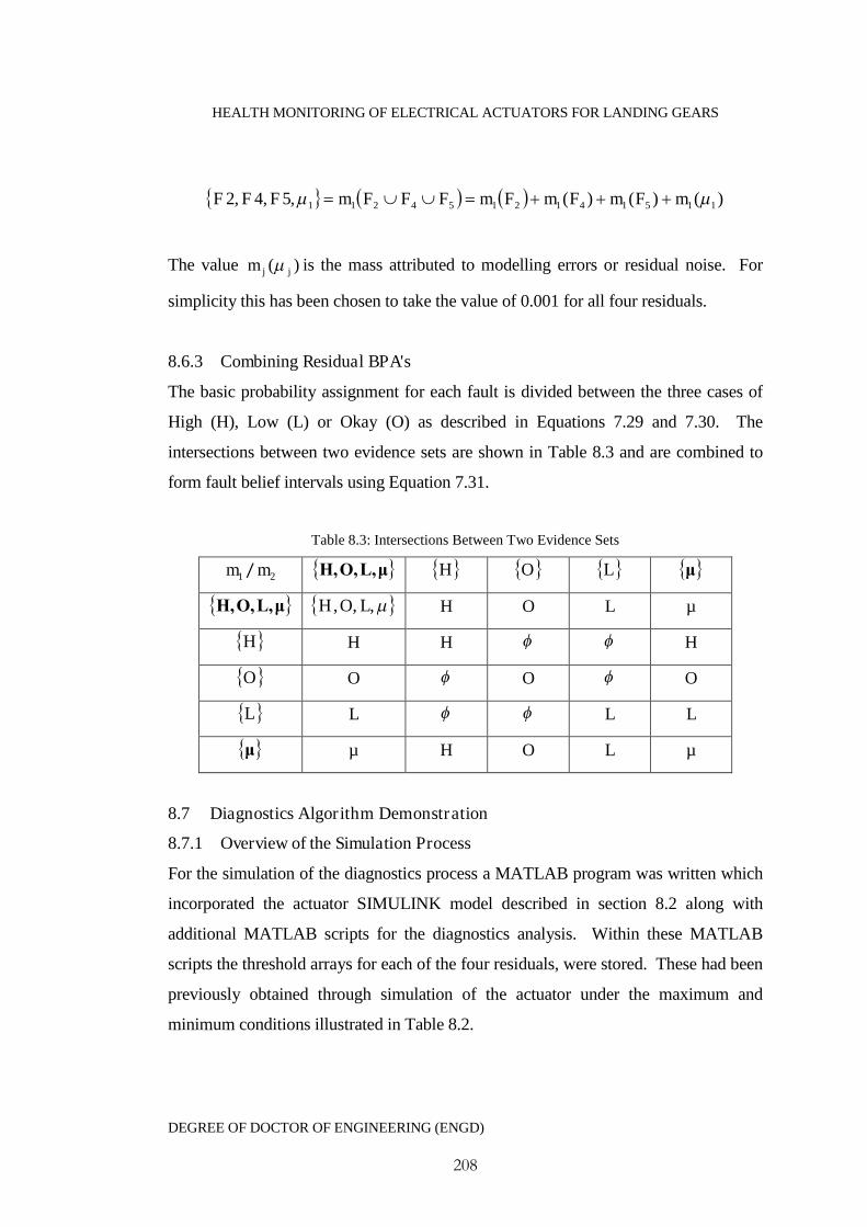
HEALTH MONITORING OF ELECTRICAL ACTUATORS FOR LANDING GEARS
DEGREE OF DOCTOR OF ENGINEERING (ENGD)
208
)()()(,5,4,2 1151412154211 mFmFmFmFFFmFFF
The value )( jjm is the mass attributed to modelling errors or residual noise. For
simplicity this has been chosen to take the value of 0.001 for all four residuals.
8.6.3 Combining Residual BPA's
The basic probability assignment for each fault is divided between the three cases of
High (H), Low (L) or Okay (O) as described in Equations 7.29 and 7.30. The
intersections between two evidence sets are shown in Table 8.3 and are combined to
form fault belief intervals using Equation 7.31.
Table 8.3: Intersections Between Two Evidence Sets
1m / 2m μL,O,H, H O L μ
μL,O,H, ,,, LOH H O L µ
H H H H
O O O O
L L L L
μ µ H O L µ
8.7 Diagnostics Algorithm Demonstration
8.7.1 Overview of the Simulation Process
For the simulation of the diagnostics process a MATLAB program was written which
incorporated the actuator SIMULINK model described in section 8.2 along with
additional MATLAB scripts for the diagnostics analysis. Within these MATLAB
scripts the threshold arrays for each of the four residuals, were stored. These had been
previously obtained through simulation of the actuator under the maximum and
minimum conditions illustrated in Table 8.2.
HEALTH MONITORING OF ELECTRICAL ACTUATORS FOR LANDING GEARS
DEGREE OF DOCTOR OF ENGINEERING (ENGD)
209
For the diagnostics simulation the user is requested to select the specific fault and its
magnitude as a percentage of its nominal value. The program then automatically
simulates the actuator model with the selected parameter/signal offset changes,
generating the necessary residuals and carrying out the evidential reasoning
diagnostics analysis.
For the purpose of demonstrating the diagnostics, changes to Fault 3 (frictional
constant) were made in the range of %40%40 . Basic probabilities are assigned
for each fault condition by automatically comparing the residual responses with the
stored fault threshold arrays resulting in a set of four evidences, relating to the
individual residuals. The calculation of the belief intervals first combined evidences
1m and 2m then individually combined the result with 3m and 4m . The purpose of
which was to illustrate how the diagnostics becomes clearer with reduced uncertainty
with additional evidences. At this point it is worth revisiting the explanation of the
evidential intervals )(),( FF fplfBel as presented in Chapter 7 for the purpose of
interpreting the diagnostics.
]1,0[Ff → No information exists regarding Ff
]0,0[Ff → Ff is false
]1,1[Ff → Ff is true
]1,3.0[Ff → The evidence partially supports Ff
]7.0,0[Ff → The evidence partially supports the negation of Ff
]7.0,3.0[Ff → The evidence partially supports both the presence and negation of
Ff .The probability of Ff is between 0.3 and 0.7 with uncertainty
0.4.
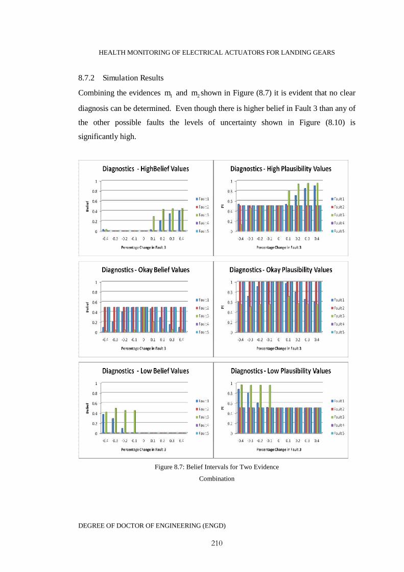
HEALTH MONITORING OF ELECTRICAL ACTUATORS FOR LANDING GEARS
DEGREE OF DOCTOR OF ENGINEERING (ENGD)
210
8.7.2 Simulation Results
Combining the evidences 1m and 2m shown in Figure (8.7) it is evident that no clear
diagnosis can be determined. Even though there is higher belief in Fault 3 than any of
the other possible faults the levels of uncertainty shown in Figure (8.10) is
significantly high.
Figure 8.7: Belief Intervals for Two Evidence
Combination
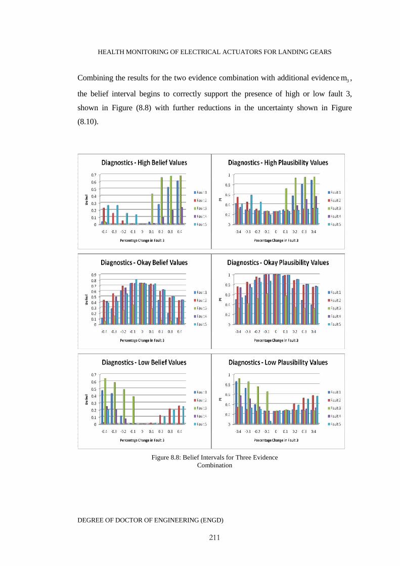
HEALTH MONITORING OF ELECTRICAL ACTUATORS FOR LANDING GEARS
DEGREE OF DOCTOR OF ENGINEERING (ENGD)
211
Combining the results for the two evidence combination with additional evidence 3m ,
the belief interval begins to correctly support the presence of high or low fault 3,
shown in Figure (8.8) with further reductions in the uncertainty shown in Figure
(8.10).
Figure 8.8: Belief Intervals for Three EvidenceCombination

HEALTH MONITORING OF ELECTRICAL ACTUATORS FOR LANDING GEARS
DEGREE OF DOCTOR OF ENGINEERING (ENGD)
212
Combining additional evidence 4m the uncertainty further reduces and the belief
interval moves further towards ]1,1[B supporting the presence of fault 3, Figure (8.9).
It however can be seen that there is also strong support for the presence of fault 1.
Even though the support for fault 3 is much stronger care would need to be taken with
this diagnosis. In a scenario such as this there is a strong case for employing an on
demand parameter estimation scheme.
Figure 8.9: Belief Intervals for Four EvidenceCombination
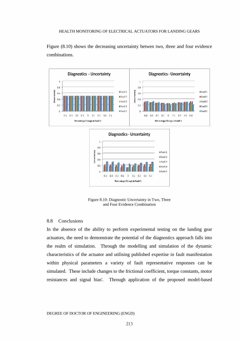
HEALTH MONITORING OF ELECTRICAL ACTUATORS FOR LANDING GEARS
DEGREE OF DOCTOR OF ENGINEERING (ENGD)
213
Figure (8.10) shows the decreasing uncertainty betwen two, three and four evidence
combinations.
Figure 8.10: Diagnostic Uncertainty in Two, Threeand Four Evidence Combination
8.8 Conclusions
In the absence of the ability to perform experimental testing on the landing gear
actuators, the need to demonstrate the potential of the diagnostics approach falls into
the realm of simulation. Through the modelling and simulation of the dynamic
characteristics of the actuator and utilising published expertise in fault manifestation
within physical parameters a variety of fault representative responses can be
simulated. These include changes to the frictional coefficient, torque constants, motor
resistances and signal bias'. Through application of the proposed model-based

HEALTH MONITORING OF ELECTRICAL ACTUATORS FOR LANDING GEARS
DEGREE OF DOCTOR OF ENGINEERING (ENGD)
214
diagnosis approach to simulation of the actuator it is clearly demonstrated there is the
ability to distinguish between this selection of parameter and signal changes.
Testing the diagnostic ability by simulating a range of negative and positive changes
to the frictional coefficient, which has been identified in the literature as a key
symptom of bearing faults, within a simulation model of the actuator model, verified
by the sponsor’s designers as representative of the current design, it has been shown
that the use of the proposed evidential reasoning process, increases the diagnostic
confidence as more evidence combinations are added.
One of the key issues which is identified is that some faults may affect the residuals in
near identical ways, for example resistance changes are not distinguishable from a
simulated bias in the speed sensor. In these cases further evidence is required, and the
use of an online parameter estimation to distinguish between sensor faults and actuator
faults is proposed.
The use of simulation to demonstrate diagnostics however does have a variety of
limiting factors in algorithm verification. Without the experimental classification of
parameter/signal changes in the presence of faults, it is difficult to accurately simulate
these faulty conditions. Also, full validation of the model would be required against
significant amounts of test data before the actuator process model could be relied
upon.
An approach such as that proposed at this stage modelling errors can only be
estimated. The simulation has assumed that the errors within each of the signals are
common, which in practice will not be the case due to measurement errors inherent in
different sensors. The first two residuals for example are more attuned to the
electrical and mechanical parts of the model; these may have differing modelling
errors affecting the individual residuals. In a similar way some common symptoms
may be stronger for one fault than for another. This insinuates that investigations into
the use of weightings for symptom to fault classification will be required.

HEALTH MONITORING OF ELECTRICAL ACTUATORS FOR LANDING GEARS
DEGREE OF DOCTOR OF ENGINEERING (ENGD)
215
8.9 References
Byington, C., Safa-Bakhsh, R., Watson, M., Kalgren, P. (2003), 'Metrics evaluation
and tool development for health and Usage Monitoring Technology', in AHS Forum.
Phoenix Arizona.
Byington, C., Watson, M. ,Edwards, D., Stoetling, P. (2004), ‘A model-based
approach to prognostics and health management for flight control actuators’,
Proceedings of the IEE Aerospace Conference,
Phillips, P., Diston, D., Payne, J., Pandya, S. (2010), ' Evidential Reasoning Applied
to Model-Based Diagnostics in Landing gear Actuators', in Machine Failure and
Prevention Technology Conference. AL, USA.
HEALTH MONITORING OF ELECTRICAL ACTUATORS FOR LANDING GEARS
DEGREE OF DOCTOR OF ENGINEERING (ENGD)
216
C h a p t e r 9 : C o n c l u s i o n s
9.1 Summary
Health monitoring technology is intractably tied up with aerospace maintenance
activities as a whole. The aerospace maintenance industry is currently facing a time of
unprecedented demand for spare parts, complete overhauls and general servicing.
This is therefore putting a strain on overhaul providers, suppliers and Original
Equipment Manufacturers (OEM) which have begun seeking new innovative
maintenance solutions, to meet rising demands and costs. The nature of this therefore
opens up the possibility of integrating health monitoring technologies into unique
customised maintenance solutions and support packages offered to aircraft operators.
It has however been the tradition that there is an inherent secretive nature regarding
aerospace maintenance. For successful tailored maintenance solutions focused upon a
more predictive approach requires a transparent flow of information from the aircraft
operators, aiding in suppliers and manufacturers optimising their spare part inventories
and developing efficient maintenance procedures/schedules.
Aerospace is often considered to be at the forefront of high technology requiring the
strictest of safety standards and criteria. This however is not necessary the case when
it comes to health monitoring technology. Very little is actually documented about
aerospace monitoring research and surprisingly little has been implemented into
aircraft systems. In the UK the railway industry has recognised the need to improve
maintenance practices after a variety of high profile rail disasters. Like aerospace, the
implementation of rail health monitoring is in an infant stage, but there is much more
transparency on the progress of research and the industry practices, likewise in the
power industry.
Many of the approaches illustrated within this research thesis have been used to
certain varying degrees of success individually within a variety of industries and this
research has sought to combine differing techniques together to form a single

HEALTH MONITORING OF ELECTRICAL ACTUATORS FOR LANDING GEARS
DEGREE OF DOCTOR OF ENGINEERING (ENGD)
217
algorithmic approach. A study of techniques and their applicability to actuation
systems across a range of industries, which included aerospace, rail, automotive and
the power industry has been carried out. The results of which identify that health
monitoring in each of these industries have in some form or another either been
implemented to some extent, or at the very least the desire to implement and develop
them, with early stages of research being evident.
9.2 Research Conclusions
At the start of this thesis a number of clear objectives were defined. In order to
conclude that each of these has been satisfied these can now be revisited.
9.2.1 Objective 1
Assess the current state of the art health monitoring techniques and show that
established techniques exist which are viable for a landing gear actuator application
without impacting upon the weight, volume or complexity of the actuators.
Health monitoring has over the past several decades become a well established
discipline with a multitude of tools and techniques. The state of the art in health
monitoring for industrial applications for example vibration analysis or acoustic
monitoring with advanced signal processing and methods such as wear debris analysis
using optical imaging and fuzzy classification all perform well. However the nature
of the actuator design and operation generates a unique set of challenges in the choice
of actuator monitoring approach. Most monitoring research aimed at linear electrical
actuator technology has converged towards the classification of estimated physical
parameters to underlying faults. This offers several advantages, being that very little
additional equipment is required, there is less dependency on measured data and the
methods can be implemented on line or offline. The downsides include the need for
an accurate process model must be developed and the accuracy of parameter
estimation techniques. The presentation of a full health monitoring technology review
presented to the sponsors as a part deliverable for the EU framework 6 projects

HEALTH MONITORING OF ELECTRICAL ACTUATORS FOR LANDING GEARS
DEGREE OF DOCTOR OF ENGINEERING (ENGD)
218
TATEM assessed the varying techniques, in terms of hardware requirements, fault
sensitivities and general issues. The review studies confirmed that the most applicable
approach to follow was to consider the use of multiple methodologies including
model-based, performance monitoring and knowledge based methods.
The reasoning behind developing a health monitoring system based upon multiple
techniques is to maximise the amount of data and knowledge available for use. It has
been identified that a fundamental problem which arises when attempting to combine
information from multiple sources is that it will usually be non-commensurate. That
unit scales and time periods will differ. Techniques and frameworks must therefore be
available to combine this data together. The research has made use of the concept of
data fusion and existing frameworks in order to identify the correct methodology for
achieving this. The use of data fusion is gaining popularity within health monitoring
community but its application to actuation systems is still regarded as in its infancy.
9.2.2 Objective 2
Define a systems architectural framework for EMA diagnostics and prognostics, with
identification of key nodes which will enable the following:
Identification of abnormal behaviour
Incorporate performance metrics
Allow analytical and heuristic symptoms to be used effectively alongside
process history, costs and risks.
Be accessible for additional sensor/heuristic data, for health monitoring
purposes, to be incorporated without architectural alterations.
The development of a conceptual framework has the purpose of acting as a template
or set of guidelines in the selection and development of individual algorithms. The
framework presented in this research combines the different levels of the OSA-CBM
health monitoring standards and the hierarchal levels of the JDL data fusion
framework in order to visually identify the important modules required in the system.
The framework design is not application specific and the individual elements have

HEALTH MONITORING OF ELECTRICAL ACTUATORS FOR LANDING GEARS
DEGREE OF DOCTOR OF ENGINEERING (ENGD)
219
been identified on a generic level. The purpose of such a framework is to ensure that
the health monitoring system development will integrate into the actuator application
rather than trying to force generic health monitoring into the actuator system.
The architectural framework, which does not directly make any commitment to
particular data streams, feature extraction or inference processes, does however
identify certain key areas of knowledge which are of importance. These are the
hierarchical objectives, from the management level through platform, system, and
subsystem and component levels. Without the formation of objectives, assessment of
the health monitoring capability and performance would be meaningless. Identifying
these objective ensure that performance metrics can be identified and incorporated
into the decision making process.
Next it is important that knowledge on the failure of components and their effects on
the overall system is known. Understanding the impact of failure effects it is best
achieved through the construction of FMEA. This heuristic knowledge can then be
used to form failure event trees. Both of these areas have been a key development part
of this research in close collaboration with the sponsors.
The knowledge of how a faulty component affects the system leads onto the notion
that a rule base is an essential part of the systems consequence inference. Rule bases
have come under much criticism due to the number of rules required and their
potential clumsiness. However it should be noted, for any monitoring system which
will provide a consequence of failure, a rule base in some form or another will be
essential. Rule bases also allow for additional heuristic or historical data or
knowledge on new previously unseen events to be easily incorporated into the
monitoring.
The framework descriptions on the fusion processes, identified as data association,
hypothesis generation/evaluation/selection and fault estimation have been used to
select the process by which the diagnostics algorithm has been formulated. The very

HEALTH MONITORING OF ELECTRICAL ACTUATORS FOR LANDING GEARS
DEGREE OF DOCTOR OF ENGINEERING (ENGD)
220
nature of basing the framework upon data fusion means that it is possible to combine
different information sources or evidences without significant architectural changes.
As long as additional information is aligned to a common reference frame it can be
combined to increase the confidence in the diagnostics reducing uncertainty.
For the introduction of health monitoring into a vehicle platform considerations need
to be made on the deployment strategy. Two separate possibilities for this have been
identified. The first is dependent on the monitoring algorithms and decision support
to be made at a maintenance service bay, where the monitoring software is located.
The second approach would see the health monitoring algorithms embedded onto the
aircraft alongside control algorithms and BIT testing. It is highly likely that for
effective aerospace vehicle monitoring a hybrid of the two deployment strategies
would be a natural approach.
9.2.3 Objective 3
Define and demonstrate a health monitoring algorithm for component level actuator
fault detection and diagnostics.
It has been an essential part of this research project that a close working dialogue with
the sponsoring organisation has been maintained to understand the necessary elements
of actuator design requirements, performance expectations and design restrictions.
Understanding these key factors has been identified as essential for the design of any
application specific aerospace health monitoring system. The health monitoring
algorithm derived in this research incorporates separated fault detection and diagnostic
approaches, with the view that diagnostic computing resources would be used only
depending upon appropriate warnings from the fault detection scheme.
It has been illustrated that to simplify the fault detection task, it would be beneficial to
utilise an estimation of the overall operating performance/quality of the actuator. To
achieve this, the algorithm makes use of the knowledge that in a healthy system there
will be strong correlations between the actuators process data. The algorithm performs
HEALTH MONITORING OF ELECTRICAL ACTUATORS FOR LANDING GEARS
DEGREE OF DOCTOR OF ENGINEERING (ENGD)
221
data reduction by identifying the most significant eigenvalues (principle components)
which capture the highest variability and projecting the data sets onto these principal
components. This means that the same information can be achieved through
reductions in the data. The fault detection is reliant upon two performance statistics
referred to as squared prediction error and a 2T - Hotellings statistics. When suspected
faulty process data is available, this data is projected onto the nominal principle
component model and these statistics are calculated. The use of fuzzy logic
classification is then used to interpret these, to extract the necessary information
regarding the actuator process quality. The application of the fuzzy logic approach
provides the user of the monitoring system a crisp numerical output describing the
actuators process quality for use in aiding in maintenance decisions.
The proposed diagnostics approach utilises a system model which acts upon the
actuators dynamic process data to generate a set of diagnostic residuals. A model of
the landing gear actuator certified by the sponsoring organisations has been developed
and the four key residuals based upon this model have been defined. The approach to
threshold evaluation used which moves away from the traditional use of ‘one
threshold per residual’ approach. Rather proposing the use of multiple thresholds for
each residual each sensitive to an individual fault. Diagnostic inaccuracies associated
with fixed static thresholds are overcome by designing thresholds which follow
dynamic profiles.
Evaluation of the residuals with respect to thresholds also moves away from the use of
traditional Boolean Logic utilising the concepts of approximate reasoning. The
approximate reasoning approach provides a measure on the extent to which a
threshold has been breached, allowing estimation to the magnitude of the fault
occurrence. With this approach incremental changes in the residuals about a threshold
will result in incremental changes to the diagnostic results. The result is recorded as a
measure known as basic probability assignments. These refer to the evidence for the
HEALTH MONITORING OF ELECTRICAL ACTUATORS FOR LANDING GEARS
DEGREE OF DOCTOR OF ENGINEERING (ENGD)
222
presence of individual faults. The use of approximate reasoning ensures that
diagnostic stability issues related to modelling errors or noise are removed
The Dempster Shafer theory of evidence is used to combine fault evidences, which is
demonstrated in this research thesis to increase the belief in the diagnostic results
whilst reducing uncertainty, with increased levels of evidence. The results of fusing
multiple evidences are a set of ranked evidential intervals based upon belief and
plausibility which are evaluated against a set of defined fusion rules.
Importantly the algorithm has been designed to only require data which will be
available from the actuators control system. This therefore meets the key design
criteria of minimising the levels of additional sensor equipment and complexities.
9.2.4 Objective 4
Demonstrate and assess the commercial benefits of incorporating health monitoring
systems into aircraft landing gears from the viewpoints of for O Manufacturers
(OEM), Suppliers, Maintenance providers and aircraft operators.
The commercial benefits of incorporating health monitoring have been assessed
through dialogue with the sponsors, in order to understand aircraft maintenance from a
holistic viewpoint. There are a variety of differing organisations whose business is
affected by aircraft maintenance practice. These include manufactures, maintenance
providers, suppliers, and aircraft operators. The nature of current maintenance practice
has been clearly identified, along with the direction towards a predictive maintenance
practice and the role in which health monitoring will play. In addition to technical
challenges associated with health monitoring there are a variety of business integration
challenges which must be understood. The key challenges are identified as the
following

HEALTH MONITORING OF ELECTRICAL ACTUATORS FOR LANDING GEARS
DEGREE OF DOCTOR OF ENGINEERING (ENGD)
223
Cost drivers: The cost drivers for each business associated with maintenance will
differ and will often be competitive. Understanding these and the differing
organisations relationships are the key to developing essential predictive maintenance
costing model. The cost drivers for OEM, MRO and aircraft operators have been
clearly identified and an approach to maintenance based upon unique customer
tailored maintenance packages, requiring information transparency is proposed.
Business Models: The sponsoring company which sees itself as a future landing gear
health monitoring solutions provider has well defined business models for their
products. Challenges include how to market the technology alongside these existing
products. Three pricing models are therefore proposed. The first considers that health
monitoring is given away at a consolidated cost differentiating the landing gear
product from those of a competitor. The second involves generating revenue based
upon sales volumes. A unit cost is paid by the landing gear customer to the health
monitoring system provider for every landing gear set using the monitoring
technology. The final model is based upon per landing gear unit. A one off payment
is made to the health monitoring provider for any given monitoring solution per
landing gear set. This ensures that the customer retains the ownership for the life of
that product.
9.3 Contribution to Knowledge
The purpose of this thesis and the overall contribution which has been made is to
bring together a combined understanding of landing gear design, health monitoring
and the business environment for aircraft maintenance in order for a holistic design
process for landing gear health monitoring to be realised.
9.4 Further Work
The development a health monitoring system for an industrial application such as
electrical actuators for Landing gears is very multidisciplinary and a holistic viewpoint
must be taken. As with all research programmes time constraints will limit further
HEALTH MONITORING OF ELECTRICAL ACTUATORS FOR LANDING GEARS
DEGREE OF DOCTOR OF ENGINEERING (ENGD)
224
development and narrow the research focus. There is however a number of
opportunities and areas, both from a technical and business perspective which must
still be investigated and developed before landing gear health monitoring can be
developed into a market ready system. A selection of these includes:
9.4.1 Experimental Landing Gear Test bed
One of the major limitations of implementing health monitoring into a landing gear
electrical actuator will be the lack of data from the new actuators. Extensive testing
would be needed to be performed prior to any in service implementation and a set of
generic fault cases will need to be developed. Data from fault case testing will enable
the classification of faults enabling the diagnostics approach to be validated
experimentally on a landing gear testing rig. Experimental classification would
enable diagnostic residuals and the fault sensitive thresholds to be designed to be
robust. In any fault related case, it is known that common symptoms will occur
between faults, with some symptoms being more prominent depending upon the
particular fault present; this brings into focus the requirement for weighting
symptoms. Experimental fault testing on a landing gear rig, under representative
operating conditions would enable fault - symptom weights to be assigned, increasing
diagnostic certainty.
9.4.2 Uncertainty and Performance Metrics
The use of a model based diagnostics system will suffer from a variety of uncertainties
which will need to be taken into account, to reduce uncertainty in the diagnostics.
Research would focus on understanding and dealing with the various sources of
uncertainty. Quantifying modelling errors, signal errors and dealing with uncertainties
in the initial lack of information. Techniques would need to be developed to handle
historical and service data as it becomes available throughout the actuators service
life. Difficulties with dealing with such information are usually associated with
incomplete or missing records.
HEALTH MONITORING OF ELECTRICAL ACTUATORS FOR LANDING GEARS
DEGREE OF DOCTOR OF ENGINEERING (ENGD)
225
It is essential that the performance of a monitoring system is known. Dialogue with
designers and experimental testing is required to quantify individual component
failure probabilities. This would allow specific component level objectives to be set
for the monitoring system. Performance metrics would then be employed, likely to be
based upon a measure of accuracy in the diagnosis. This measure of accuracy would
be calculated through measures such as probability of false alarm, correct alarm,
missed alarm etc. If a monitoring system cannot meet specified objectives then
reliance upon it would have an adverse effect upon the aircraft safety.
9.4.3 New Sensor Technology and Systems Integration
This research has put a strong emphasis on the need to keep a diagnostics systems
affects on the actuators weight and complexity to a minimum. The thesis review work
briefly highlights the emergence of new sensor technologies. Future research areas
should focus on monitoring solutions using wireless smart sensors with inbuilt signal
processing that can perform all monitoring tasks. The benefits of these are that they
are lightweight, do not require additional cabling, creates a reduction in the demand
for aircraft computing resources. These advantages opens new doors for the
investigation of monitoring techniques which have been deemed inapplicable with
conventional sensor technology.
Systems integration research would need to be undertaken to ensure that any future
monitoring system can not only integrate into the landing gear subsystems, but can
also integrate seamlessly into the aircraft systems as a whole and if necessary work
alongside aircraft BIT and any other local monitoring systems.
9.4.4 Cost Modelling
The introduction of a health monitoring based maintenance system would have a
direct impact upon the through life support costs and processes of the landing gear
equipment. The research into potential novel approaches to predict the through-life
manufacture and repair costs for long life actuator products would be fundamental for
decision making. Information from a monitoring diagnostics system incorporated into
HEALTH MONITORING OF ELECTRICAL ACTUATORS FOR LANDING GEARS
DEGREE OF DOCTOR OF ENGINEERING (ENGD)
226
costing models would be aimed at enabling the supply chain to predict, evaluate and
optimise their operations for repair and maintenance. Costing research would require
a focus on developing risk and uncertainty service metrics, assessments of
organisational relationships and the identification and quantification of the various
cost drivers.
9.4.5 Remaining Life Models
This research has been focused entirely upon diagnostics. However it is the industries
desire to extend diagnostics into the realm of fault prognosis, returning remaining
useful life estimations. A case based empirical study would be required to produce
data sets observed from in service reports. The empirical data would then be used to
generate an in service benchmark model the value of which would be to establish the
remaining useful life of the system, or individual component. Remaining useful life
models typically use measures such as operating hours, however for the landing gear
application a remaining useful life measured in terms of 'number of cycles' would be
more appropriate. Such a remaining useful life model would offer invaluable
information in regards to generating an aircraft maintenance strategy.
9.5 Published Research Papers
As part of this research the following peer reviewed papers have been published or
submitted for review.
9.5.1 Journal Papers
Phillips, P., Diston, D., (2011), "A knowledge driven approach to aerospace condition
monitoring", Knowledge-Based Systems, Vol 24 (6), pp. 915 - 927
Phillips, P., Diston, D., Starr, A., (2011), "perspectives on the commercial
development of landing gear health monitoring systems", Transportation Research
Part C: Emerging Technologies, Article in Press

HEALTH MONITORING OF ELECTRICAL ACTUATORS FOR LANDING GEARS
DEGREE OF DOCTOR OF ENGINEERING (ENGD)
227
Phillips, P., Diston, D., Starr, A., (2011), "Towards a business enterprise strategy to
support the integration of proactive aerospace maintenance technologies", INSIGHT:
non-Destructive Testing and Condition Monitoring", Article in Press
9.5.2 Peer Reviewed Conference Contributions
Phillips, P., Diston, D., Payne, J., Pandya, S., Starr, A. (2008) “The application of
condition monitoring methodologies for the certification of reliability in electric
landing gear actuators”, The 5th International Conference on Condition Monitoring
and Machine Failure Prevention Technologies, Edinburgh, UK
Phillips, P., Diston, D., Starr, A., Payne, J., Pandya, S. (2009) “A review on the
optimisation of aircraft maintenance with application to landing gears”, The 4th World
Congress on Engineering Asset Management and Intelligent Maintenance Systems,
Athens, Greece
Phillips, P., Diston, D., Payne, J., Pandya S., (2010) ‘Evidential reasoning applied to
model-based diagnostics in landing gear actuators’, Machine Failure and Prevention
Technology Conference, AL, USA
Phillips, P., Diston, D., (2010) ‘An intelligent health monitoring framework for a
motor-driven actuator’, Proceeding on the 7th International Conference on Condition
Monitoring and Machine Failure Technologies, Edinburgh, UK


![Numerical modeling of electrical-mechanical …Piezoelectric patch actuators have also been evaluated as the driving parts of this loudspeaker [3]. The electromagnetic actuators, which](https://img.pdfslide.us/doc/110x75/5f521f4696c37455d619fc26/numerical-modeling-of-electrical-mechanical-piezoelectric-patch-actuators-have-also.jpg)