Embed Size (px)
Citation preview

HEADSIGHT® HHC for NH-TR
Combine Manual 09010305
i
About Headsight Headsight Contact Info Headsight, Inc 3529 Fir Road Bremen, IN 46506 Phone:574-546-5022 Fax: 574-546-5760 Email: [email protected] Web: www.headsight.com
Technical Assistance Phone: 574-220-5511
About this Manual How to use this manual
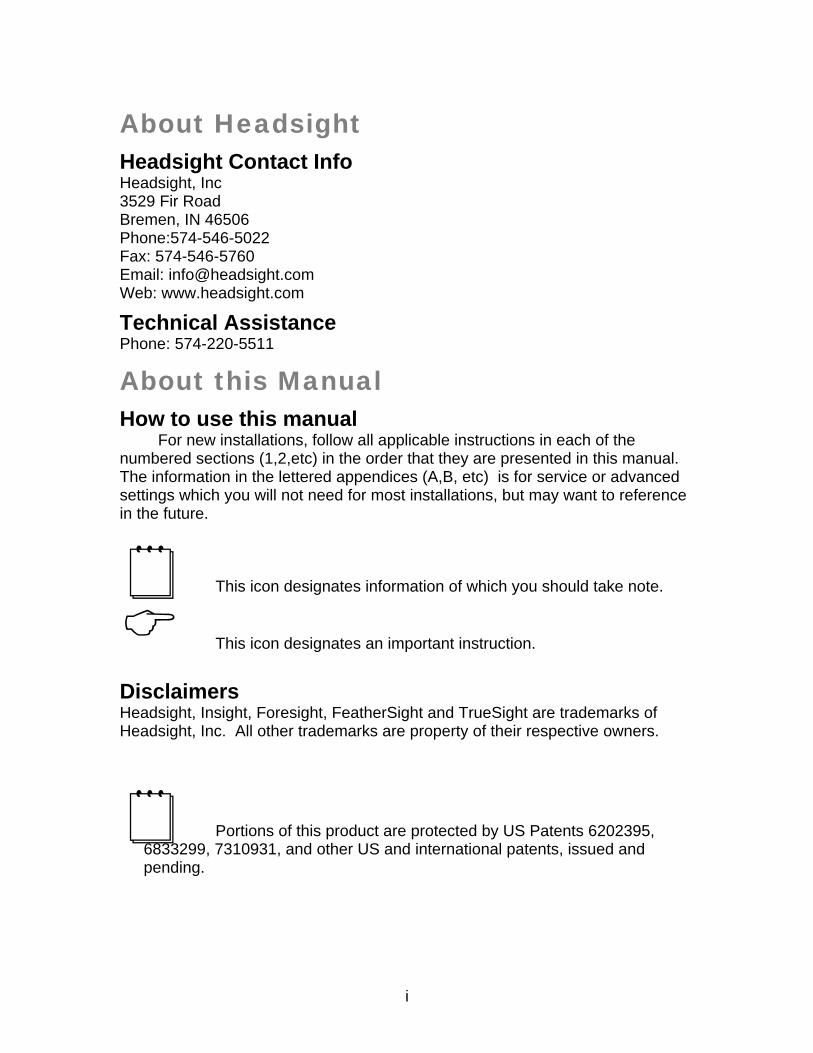
For new installations, follow all applicable instructions in each of the numbered sections (1,2,etc) in the order that they are presented in this manual. The information in the lettered appendices (A,B, etc) is for service or advanced settings which you will not need for most installations, but may want to reference in the future.
This icon designates information of which you should take note.
This icon designates an important instruction.
Disclaimers Headsight, Insight, Foresight, FeatherSight and TrueSight are trademarks of Headsight, Inc. All other trademarks are property of their respective owners.
Portions of this product are protected by US Patents 6202395, 6833299, 7310931, and other US and international patents, issued and pending.
ii
Table of Contents About Headsight i
Headsight Contact Info i Technical Assistance i
About this Manual i
How to use this manual i Disclaimers i
1. System Application 1
2. Installation 1
2.1. Control Unit 1 2.2. Main Harness 2 2.3. Header Harness 7
3. CNH Flex headers 8
3.1. NH 74C sensor modification 8 3.2. CIH 2020 sensor modification 8 3.3. 74C adjustments 9
3.3.1. Initial adjustment: all 74C heads 9 3.3.2. Maintenance: all 74C heads 10
3.4. 74C sensor calibration 11 3.4.1. Measuring voltage 11 3.4.2. Pre-2007 headers 11 3.4.3. 2007—up headers 11 3.4.4. Final adjustment 11
4. Calibration 12
4.1. Sensor Calibration (exc. 74C) 12
5. Settings 14
5.1. Combine Settings 14 5.1.1. Header drop and raise rates 14 5.1.2. Hydraulic accumulator 15
6. Operation 16
6.1. Control Unit Layout 16 6.2. Enabling Height Control 16 6.3. Adjusting Header Height 17 6.4. Adjusting Height Sensitivity 17
iii
6.5. Adjusting Tilt Sensitivity 17
A. Theory of Operation 18
B. Troubleshooting…..by Symptom 20
C. Troubleshooting…Common Harvester Problems 24
D. Wiring 25
E. Parts 26
F. Warranty Information 27
1
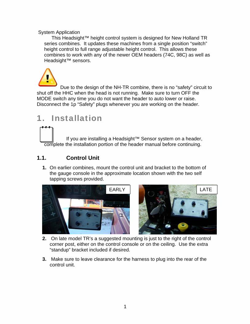
System Application This Headsight™ height control system is designed for New Holland TR
series combines. It updates these machines from a single position “switch” height control to full range adjustable height control. This allows these combines to work with any of the newer OEM headers (74C, 98C) as well as Headsight™ sensors.
Due to the design of the NH-TR combine, there is no “safety” circuit to shut off the HHC when the head is not running. Make sure to turn OFF the MODE switch any time you do not want the header to auto lower or raise. Disconnect the 1p “Safety” plugs whenever you are working on the header.
1. Installation
If you are installing a Headsight™ Sensor system on a header, complete the installation portion of the header manual before continuing.
1.1. Control Unit
1. On earlier combines, mount the control unit and bracket to the bottom of the gauge console in the approximate location shown with the two self tapping screws provided.
2. On late model TR’s a suggested mounting is just to the right of the control corner post, either on the control console or on the ceiling. Use the extra “standup” bracket included if desired.
3. Make sure to leave clearance for the harness to plug into the rear of the control unit.
EARLY LATE
2
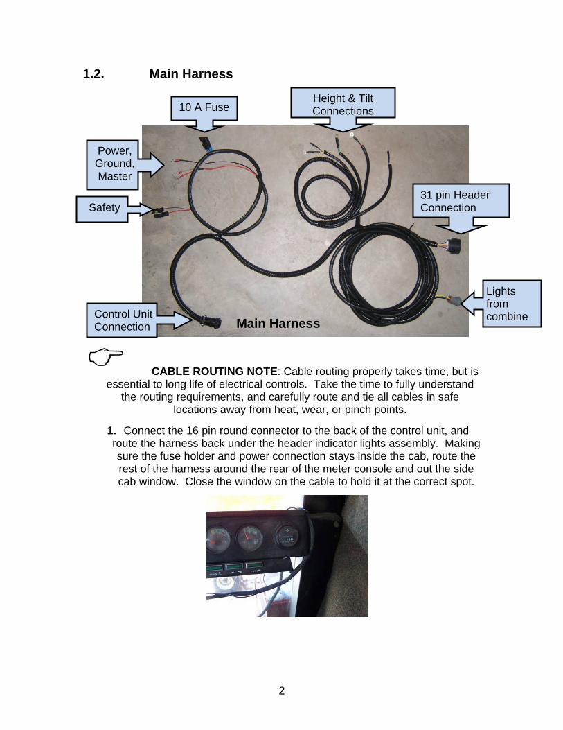
1.2. Main Harness
CABLE ROUTING NOTE: Cable routing properly takes time, but is essential to long life of electrical controls. Take the time to fully understand
the routing requirements, and carefully route and tie all cables in safe locations away from heat, wear, or pinch points.
1. Connect the 16 pin round connector to the back of the control unit, and route the harness back under the header indicator lights assembly. Making sure the fuse holder and power connection stays inside the cab, route the rest of the harness around the rear of the meter console and out the side cab window. Close the window on the cable to hold it at the correct spot.
Main Harness
31 pin Header Connection
Power, Ground, Master
Control Unit Connection
10 A Fuse
Lights from combine
Height & Tilt Connections
Safety
3
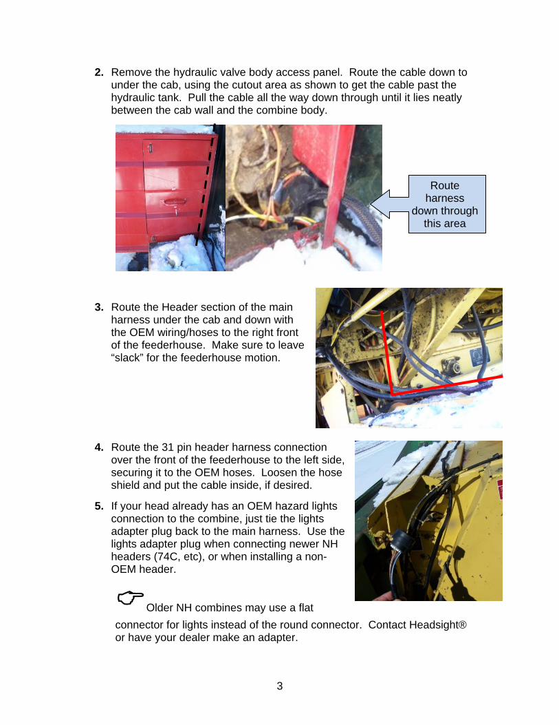
2. Remove the hydraulic valve body access panel. Route the cable down to under the cab, using the cutout area as shown to get the cable past the hydraulic tank. Pull the cable all the way down through until it lies neatly between the cab wall and the combine body.
3. Route the Header section of the main harness under the cab and down with the OEM wiring/hoses to the right front of the feederhouse. Make sure to leave “slack” for the feederhouse motion.
4. Route the 31 pin header harness connection over the front of the feederhouse to the left side, securing it to the OEM hoses. Loosen the hose shield and put the cable inside, if desired.
5. If your head already has an OEM hazard lights connection to the combine, just tie the lights adapter plug back to the main harness. Use the lights adapter plug when connecting newer NH headers (74C, etc), or when installing a non-OEM header.
Older NH combines may use a flat
connector for lights instead of the round connector. Contact Headsight® or have your dealer make an adapter.
Route harness
down through this area
4
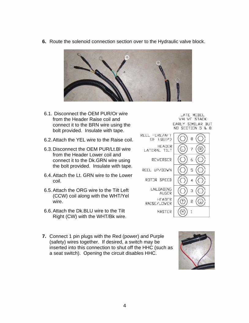
6. Route the solenoid connection section over to the Hydraulic valve block.
6.1. Disconnect the OEM PUR/Or wire from the Header Raise coil and connect it to the BRN wire using the bolt provided. Insulate with tape.
6.2. Attach the YEL wire to the Raise coil.
6.3. Disconnect the OEM PUR/Lt.Bl wire from the Header Lower coil and connect it to the Dk.GRN wire using the bolt provided. Insulate with tape.
6.4. Attach the Lt. GRN wire to the Lower coil.
6.5. Attach the ORG wire to the Tilt Left (CCW) coil along with the WHT/Yel wire.
6.6. Attach the Dk.BLU wire to the Tilt Right (CW) with the WHT/Bk wire.
7. Connect 1 pin plugs with the Red (power) and Purple (safety) wires together. If desired, a switch may be inserted into this connection to shut off the HHC (such as a seat switch). Opening the circuit disables HHC.
5
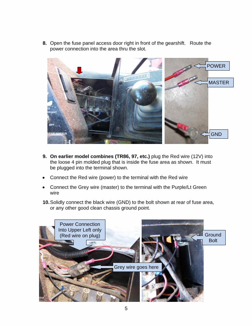
8. Open the fuse panel access door right in front of the gearshift. Route the power connection into the area thru the slot.
9. On earlier model combines (TR86, 97, etc.) plug the Red wire (12V) into the loose 4 pin molded plug that is inside the fuse area as shown. It must be plugged into the terminal shown.
Connect the Red wire (power) to the terminal with the Red wire
Connect the Grey wire (master) to the terminal with the Purple/Lt Green wire
10. Solidly connect the black wire (GND) to the bolt shown at rear of fuse area, or any other good clean chassis ground point.
Power Connection Into Upper Left only (Red wire on plug) Ground
Bolt
Grey wire goes here
POWER
MASTER
GND
6
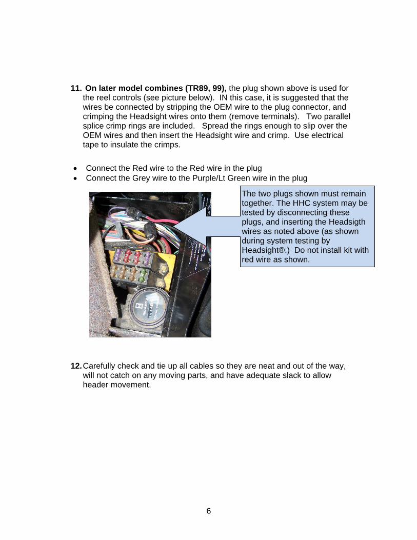
11. On later model combines (TR89, 99), the plug shown above is used for the reel controls (see picture below). IN this case, it is suggested that the wires be connected by stripping the OEM wire to the plug connector, and crimping the Headsight wires onto them (remove terminals). Two parallel splice crimp rings are included. Spread the rings enough to slip over the OEM wires and then insert the Headsight wire and crimp. Use electrical tape to insulate the crimps.
Connect the Red wire to the Red wire in the plug Connect the Grey wire to the Purple/Lt Green wire in the plug
12. Carefully check and tie up all cables so they are neat and out of the way, will not catch on any moving parts, and have adequate slack to allow header movement.
The two plugs shown must remain together. The HHC system may be tested by disconnecting these plugs, and inserting the Headsigth wires as noted above (as shown during system testing by Headsight®.) Do not install kit with red wire as shown.
7
1.3. Header Harness
1. For 74C, 98C type headers with preexisting sensors
For 98C type heads, no adapter harness is necessary, attach the header connector directly.
For 74C headers, no adapter harness is necessary. However the right sensor must be reversed electrically. Please see the instructions under 3: CNH Flex headers for directions
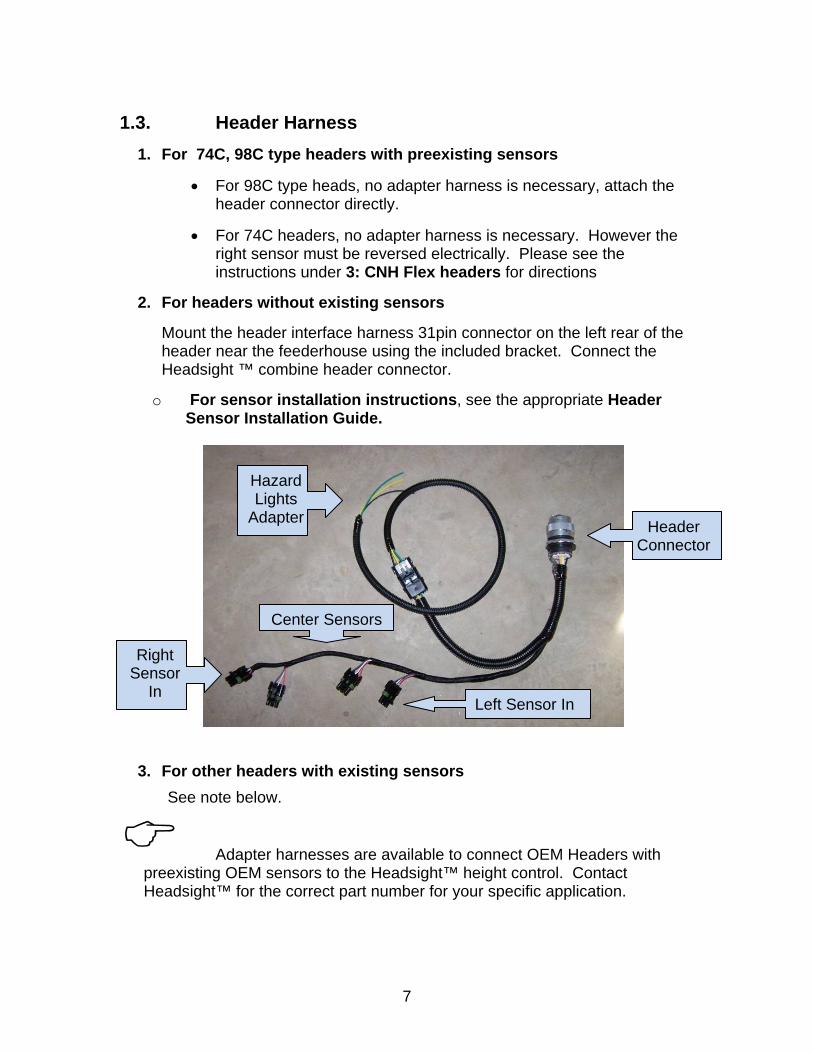
2. For headers without existing sensors
Mount the header interface harness 31pin connector on the left rear of the header near the feederhouse using the included bracket. Connect the Headsight ™ combine header connector.
o For sensor installation instructions, see the appropriate Header Sensor Installation Guide.
3. For other headers with existing sensors
See note below.
Adapter harnesses are available to connect OEM Headers with preexisting OEM sensors to the Headsight™ height control. Contact Headsight™ for the correct part number for your specific application.
Header Connector
Left Sensor In
Right Sensor
In
Center Sensors
Hazard Lights
Adapter
8
2. CNH Flex headers
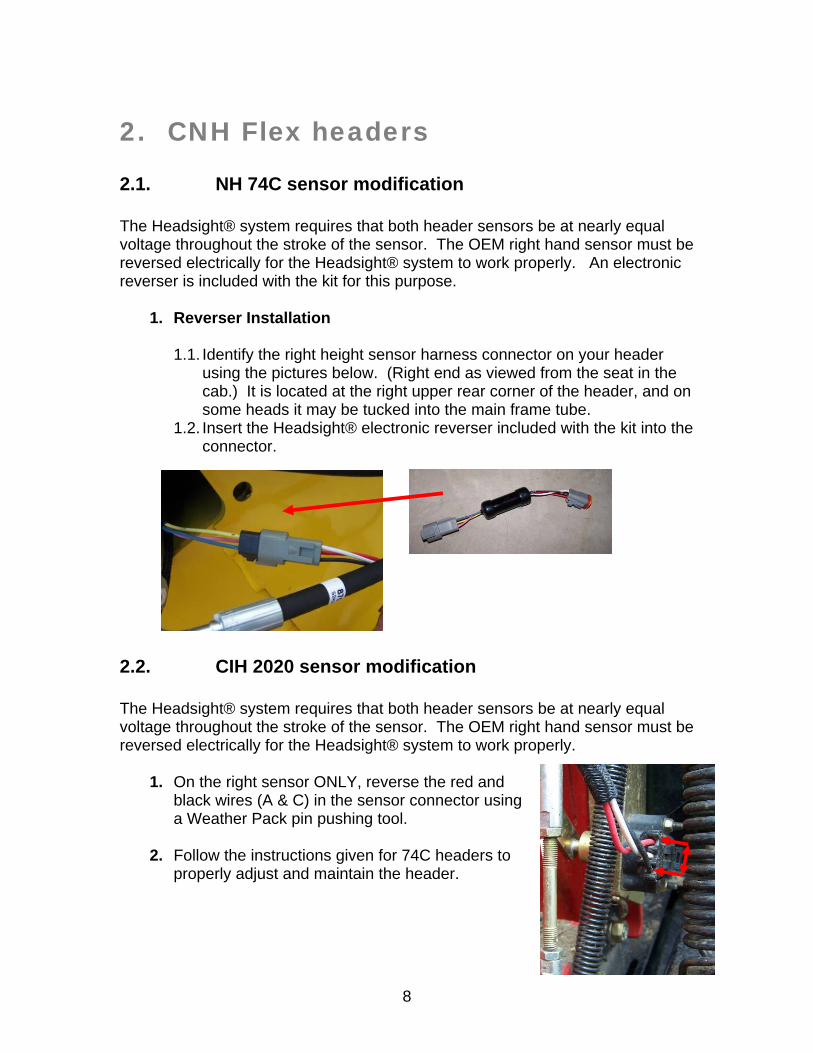
2.1. NH 74C sensor modification The Headsight® system requires that both header sensors be at nearly equal voltage throughout the stroke of the sensor. The OEM right hand sensor must be reversed electrically for the Headsight® system to work properly. An electronic reverser is included with the kit for this purpose.
1. Reverser Installation
1.1. Identify the right height sensor harness connector on your header
using the pictures below. (Right end as viewed from the seat in the cab.) It is located at the right upper rear corner of the header, and on some heads it may be tucked into the main frame tube.
1.2. Insert the Headsight® electronic reverser included with the kit into the connector.
2.2. CIH 2020 sensor modification The Headsight® system requires that both header sensors be at nearly equal voltage throughout the stroke of the sensor. The OEM right hand sensor must be reversed electrically for the Headsight® system to work properly.
1. On the right sensor ONLY, reverse the red and black wires (A & C) in the sensor connector using a Weather Pack pin pushing tool.
2. Follow the instructions given for 74C headers to properly adjust and maintain the header.
9
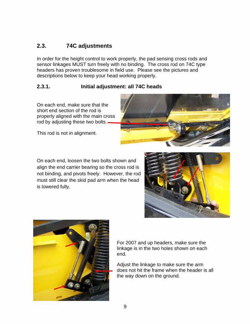
2.3. 74C adjustments In order for the height control to work properly, the pad sensing cross rods and sensor linkages MUST turn freely with no binding. The cross rod on 74C type headers has proven troublesome in field use. Please see the pictures and descriptions below to keep your head working properly.
2.3.1. Initial adjustment: all 74C heads On each end, make sure that the short end section of the rod is properly aligned with the main cross rod by adjusting these two bolts. This rod is not in alignment.
On each end, loosen the two bolts shown and align the end carrier bearing so the cross rod is not binding, and pivots freely. However, the rod must still clear the skid pad arm when the head is lowered fully.
For 2007 and up headers, make sure the linkage is in the two holes shown on each end.
Adjust the linkage to make sure the arm does not hit the frame when the header is all the way down on the ground.
10
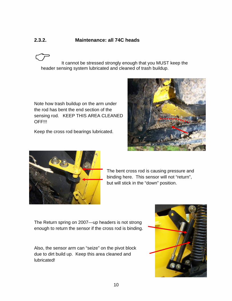
2.3.2. Maintenance: all 74C heads
It cannot be stressed strongly enough that you MUST keep the header sensing system lubricated and cleaned of trash buildup.
Note how trash buildup on the arm under the rod has bent the end section of the sensing rod. KEEP THIS AREA CLEANED OFF!!!
Keep the cross rod bearings lubricated.
The bent cross rod is causing pressure and binding here. This sensor will not “return”, but will stick in the “down” position.
The Return spring on 2007—up headers is not strong enough to return the sensor if the cross rod is binding.
Also, the sensor arm can “seize” on the pivot block due to dirt build up. Keep this area cleaned and lubricated!
11
2.4. 74C sensor calibration The goal of calibration is to make both sensors “see” the same ground height, so the head cuts level. Thus, both sensors should have the same output voltage (+/- 0.2V) when the header is sitting level. The easiest place to adjust this is when the head is sitting flat on the ground on a level surface.
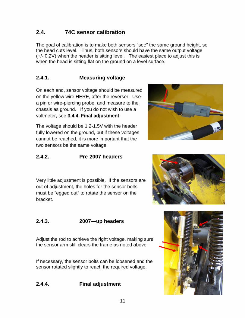
2.4.1. Measuring voltage On each end, sensor voltage should be measured on the yellow wire HERE, after the reverser. Use a pin or wire-piercing probe, and measure to the chassis as ground. If you do not wish to use a voltmeter, see 3.4.4. Final adjustment
The voltage should be 1.2-1.5V with the header fully lowered on the ground, but if these voltages cannot be reached, it is more important that the two sensors be the same voltage.
2.4.2. Pre-2007 headers Very little adjustment is possible. If the sensors are out of adjustment, the holes for the sensor bolts must be “egged out” to rotate the sensor on the bracket.
2.4.3. 2007—up headers Adjust the rod to achieve the right voltage, making sure the sensor arm still clears the frame as noted above. If necessary, the sensor bolts can be loosened and the sensor rotated slightly to reach the required voltage.
2.4.4. Final adjustment
12
If the header still does not cut level after the above adjustments, the sensors can be “tweaked” to achieve level at the selected cutting height. Simply adjust either sensor until the header sits level at the selected cutting height.
3. Calibration
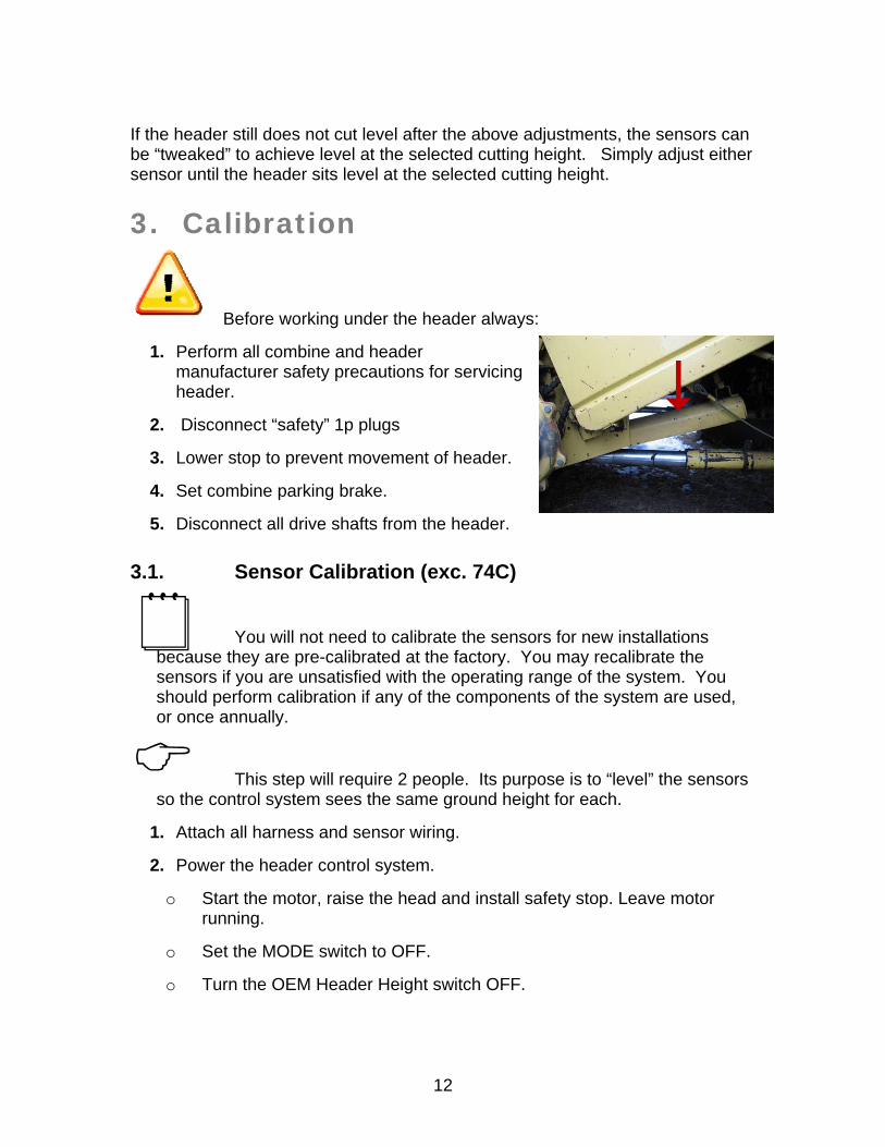
Before working under the header always:
1. Perform all combine and header manufacturer safety precautions for servicing header.
2. Disconnect “safety” 1p plugs
3. Lower stop to prevent movement of header.
4. Set combine parking brake.
5. Disconnect all drive shafts from the header.
3.1. Sensor Calibration (exc. 74C)
You will not need to calibrate the sensors for new installations because they are pre-calibrated at the factory. You may recalibrate the sensors if you are unsatisfied with the operating range of the system. You should perform calibration if any of the components of the system are used, or once annually.
This step will require 2 people. Its purpose is to “level” the sensors so the control system sees the same ground height for each.
1. Attach all harness and sensor wiring.
2. Power the header control system.
o Start the motor, raise the head and install safety stop. Leave motor running.
o Set the MODE switch to OFF.
o Turn the OEM Header Height switch OFF.
13
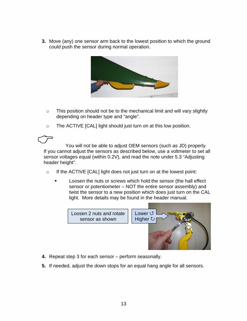
3. Move (any) one sensor arm back to the lowest position to which the ground could push the sensor during normal operation.
o This position should not be to the mechanical limit and will vary slightly depending on header type and “angle”.
o The ACTIVE [CAL] light should just turn on at this low position.
You will not be able to adjust OEM sensors (such as JD) properly. If you cannot adjust the sensors as described below, use a voltmeter to set all sensor voltages equal (within 0.2V), and read the note under 5.3 “Adjusting header height”.
o If the ACTIVE [CAL] light does not just turn on at the lowest point:
Loosen the nuts or screws which hold the sensor (the hall effect sensor or potentiometer – NOT the entire sensor assembly) and twist the sensor to a new position which does just turn on the CAL light. More details may be found in the header manual.
4. Repeat step 3 for each sensor – perform seasonally.
5. If needed, adjust the down stops for an equal hang angle for all sensors.
Lower Higher
Loosen 2 nuts and rotate sensor as shown
14
4. Settings
4.1. Combine Settings
Properly setting the combine is essential to having responsive header control. You should become very familiar with the steps in this section.
Set the automatic drop rate as high as you like without causing head “hunting”. If the head “hunts”, decrease the automatic drop rate.
See owner’s manual for location of drop rate valve and accumulator.
4.1.1. Header drop and raise rates
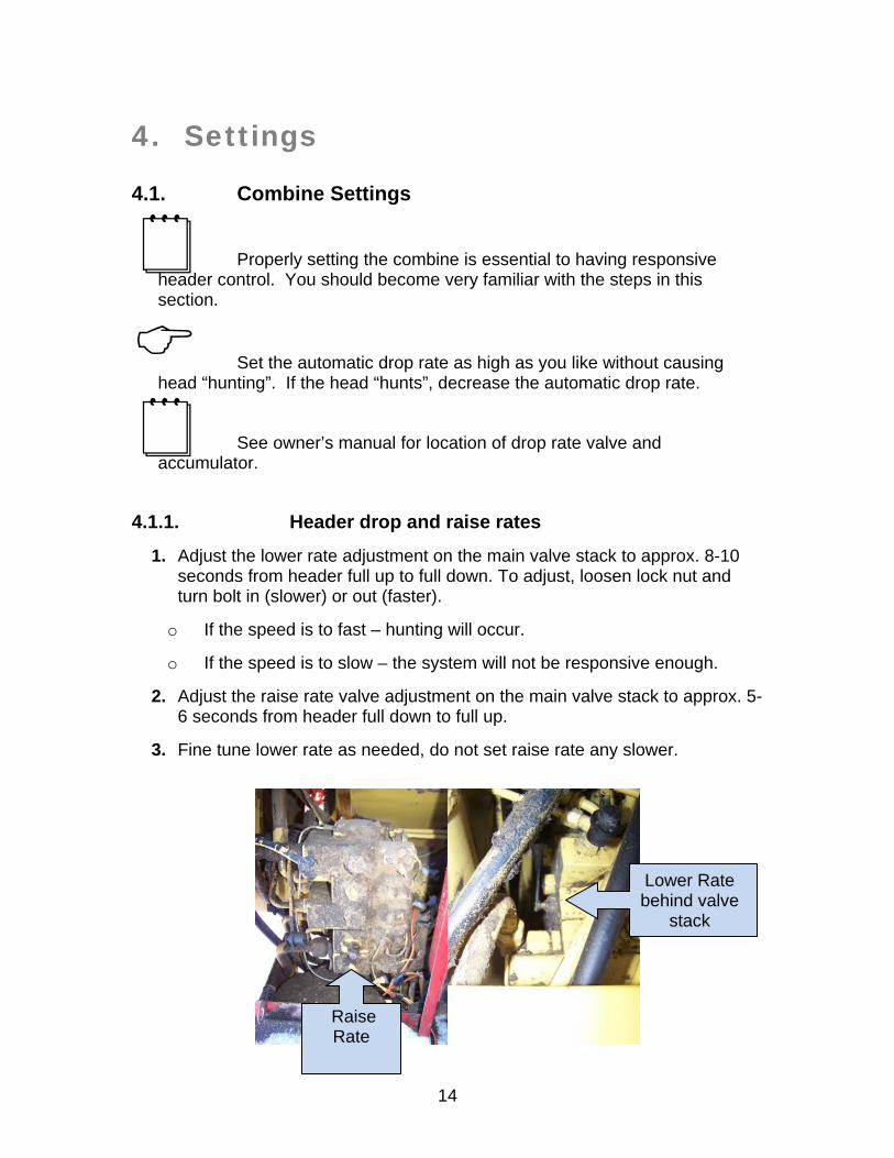
1. Adjust the lower rate adjustment on the main valve stack to approx. 8-10 seconds from header full up to full down. To adjust, loosen lock nut and turn bolt in (slower) or out (faster).
o If the speed is to fast – hunting will occur.
o If the speed is to slow – the system will not be responsive enough.
2. Adjust the raise rate valve adjustment on the main valve stack to approx. 5-6 seconds from header full down to full up.
3. Fine tune lower rate as needed, do not set raise rate any slower.
Raise Rate
Lower Rate behind valve
stack
15
4.1.2. Hydraulic accumulator
If you do not have any accumulator, please contact either your local dealer or Headsight™ to install one. It will result in much improved operation and less stress to both you and the machine in all situations, manual or auto.
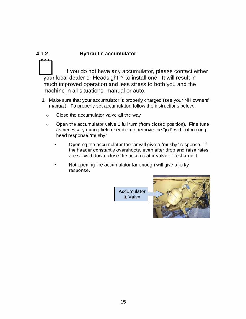
1. Make sure that your accumulator is properly charged (see your NH owners’ manual). To properly set accumulator, follow the instructions below.
o Close the accumulator valve all the way
o Open the accumulator valve 1 full turn (from closed position). Fine tune as necessary during field operation to remove the “jolt” without making head response “mushy”
Opening the accumulator too far will give a “mushy” response. If the header constantly overshoots, even after drop and raise rates are slowed down, close the accumulator valve or recharge it.
Not opening the accumulator far enough will give a jerky response.
Accumulator & Valve
16
5. Operation
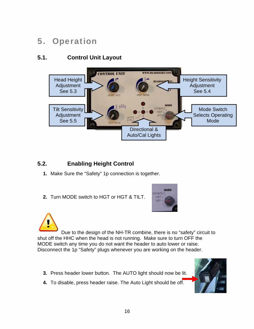
5.1. Control Unit Layout
5.2. Enabling Height Control
1. Make Sure the “Safety” 1p connection is together.
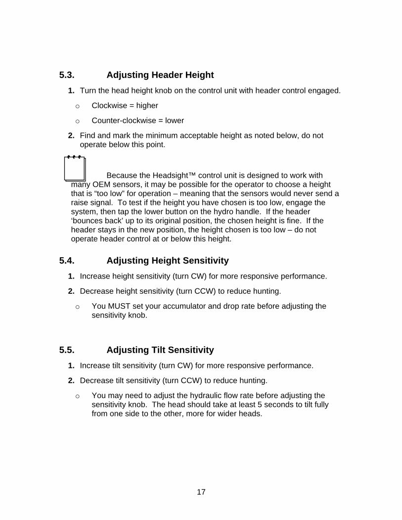
2. Turn MODE switch to HGT or HGT & TILT.
Due to the design of the NH-TR combine, there is no “safety” circuit to shut off the HHC when the head is not running. Make sure to turn OFF the MODE switch any time you do not want the header to auto lower or raise. Disconnect the 1p “Safety” plugs whenever you are working on the header.
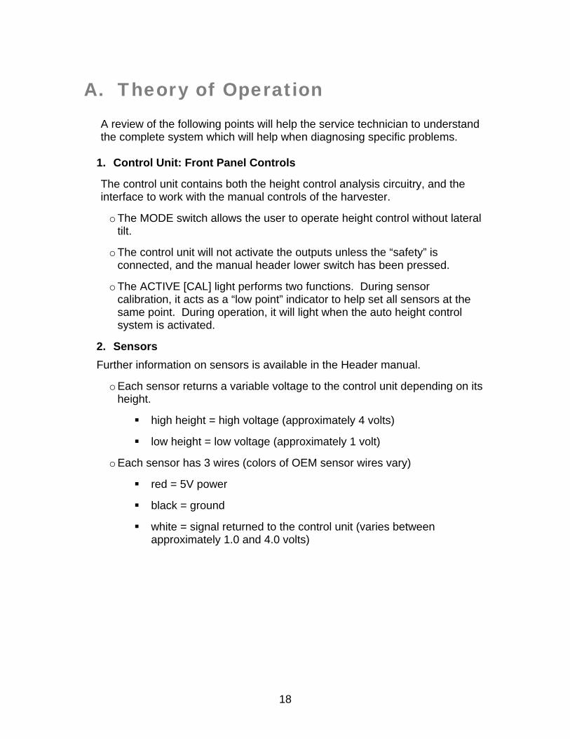
3. Press header lower button. The AUTO light should now be lit.
4. To disable, press header raise. The Auto Light should be off.
Head Height Adjustment
See 5.3
Tilt Sensitivity Adjustment
See 5.5
Height Sensitivity Adjustment
See 5.4
Mode Switch Selects Operating
Mode
Directional & Auto/Cal Lights
17
5.3. Adjusting Header Height
1. Turn the head height knob on the control unit with header control engaged.
o Clockwise = higher
o Counter-clockwise = lower
2. Find and mark the minimum acceptable height as noted below, do not operate below this point.
Because the Headsight™ control unit is designed to work with many OEM sensors, it may be possible for the operator to choose a height that is “too low” for operation – meaning that the sensors would never send a raise signal. To test if the height you have chosen is too low, engage the system, then tap the lower button on the hydro handle. If the header ‘bounces back’ up to its original position, the chosen height is fine. If the header stays in the new position, the height chosen is too low – do not operate header control at or below this height.
5.4. Adjusting Height Sensitivity
1. Increase height sensitivity (turn CW) for more responsive performance.
2. Decrease height sensitivity (turn CCW) to reduce hunting.
o You MUST set your accumulator and drop rate before adjusting the sensitivity knob.
5.5. Adjusting Tilt Sensitivity
1. Increase tilt sensitivity (turn CW) for more responsive performance.
2. Decrease tilt sensitivity (turn CCW) to reduce hunting.
o You may need to adjust the hydraulic flow rate before adjusting the sensitivity knob. The head should take at least 5 seconds to tilt fully from one side to the other, more for wider heads.
18
A. Theory of Operation A review of the following points will help the service technician to understand the complete system which will help when diagnosing specific problems.
1. Control Unit: Front Panel Controls
The control unit contains both the height control analysis circuitry, and the interface to work with the manual controls of the harvester.
o The MODE switch allows the user to operate height control without lateral tilt.
o The control unit will not activate the outputs unless the “safety” is connected, and the manual header lower switch has been pressed.
o The ACTIVE [CAL] light performs two functions. During sensor calibration, it acts as a “low point” indicator to help set all sensors at the same point. During operation, it will light when the auto height control system is activated.
2. Sensors
Further information on sensors is available in the Header manual.
o Each sensor returns a variable voltage to the control unit depending on its height.
high height = high voltage (approximately 4 volts)
low height = low voltage (approximately 1 volt)
o Each sensor has 3 wires (colors of OEM sensor wires vary)
red = 5V power
black = ground
white = signal returned to the control unit (varies between approximately 1.0 and 4.0 volts)
19
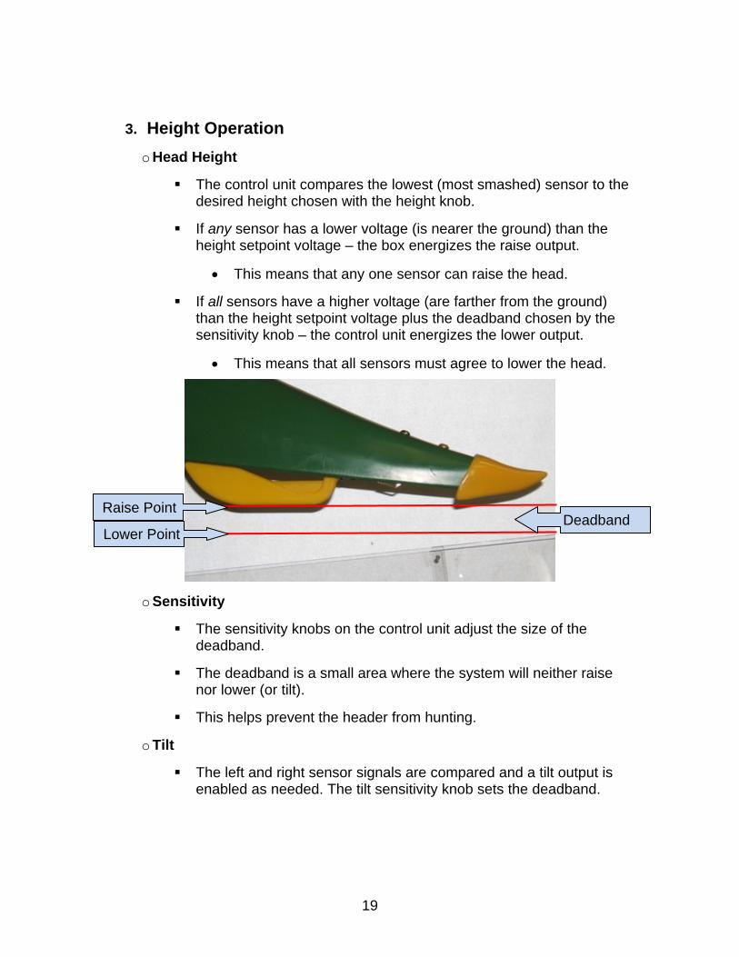
3. Height Operation
o Head Height
The control unit compares the lowest (most smashed) sensor to the desired height chosen with the height knob.
If any sensor has a lower voltage (is nearer the ground) than the height setpoint voltage – the box energizes the raise output.
This means that any one sensor can raise the head.
If all sensors have a higher voltage (are farther from the ground) than the height setpoint voltage plus the deadband chosen by the sensitivity knob – the control unit energizes the lower output.
This means that all sensors must agree to lower the head.
o Sensitivity
The sensitivity knobs on the control unit adjust the size of the deadband.
The deadband is a small area where the system will neither raise nor lower (or tilt).
This helps prevent the header from hunting.
o Tilt
The left and right sensor signals are compared and a tilt output is enabled as needed. The tilt sensitivity knob sets the deadband.
Raise Point
Lower Point Deadband
20
B. Troubleshooting…..by Symptom
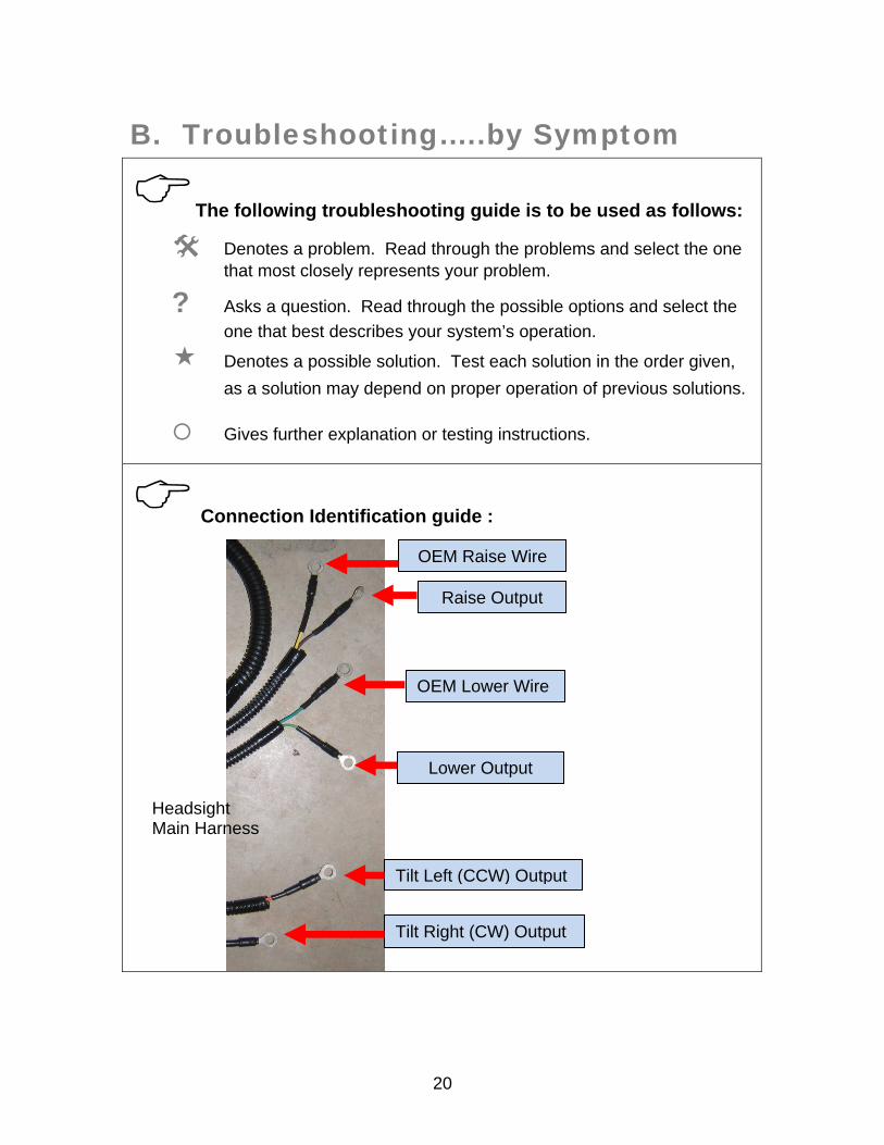
The following troubleshooting guide is to be used as follows:
Denotes a problem. Read through the problems and select the one that most closely represents your problem.
? Asks a question. Read through the possible options and select the
one that best describes your system’s operation.
Denotes a possible solution. Test each solution in the order given,
as a solution may depend on proper operation of previous solutions.
Gives further explanation or testing instructions.
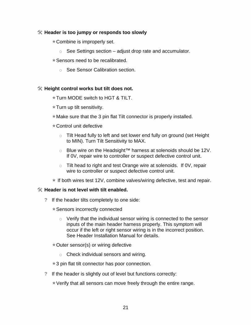
Connection Identification guide :
Headsight Main Harness
Lower Output
Raise Output
Tilt Right (CW) Output
Tilt Left (CCW) Output
OEM Lower Wire
OEM Raise Wire
21
Header is too jumpy or responds too slowly
Combine is improperly set.
o See Settings section – adjust drop rate and accumulator.
Sensors need to be recalibrated.
o See Sensor Calibration section.
Height control works but tilt does not.
Turn MODE switch to HGT & TILT.
Turn up tilt sensitivity.
Make sure that the 3 pin flat Tilt connector is properly installed.
Control unit defective
o Tilt Head fully to left and set lower end fully on ground (set Height to MIN). Turn Tilt Sensitivity to MAX.
o Blue wire on the Headsight™ harness at solenoids should be 12V. If 0V, repair wire to controller or suspect defective control unit.
o Tilt head to right and test Orange wire at solenoids. If 0V, repair wire to controller or suspect defective control unit.
If both wires test 12V, combine valves/wiring defective, test and repair.
Header is not level with tilt enabled.
? If the header tilts completely to one side:
Sensors incorrectly connected
o Verify that the individual sensor wiring is connected to the sensor inputs of the main header harness properly. This symptom will occur if the left or right sensor wiring is in the incorrect position. See Header Installation Manual for details.
Outer sensor(s) or wiring defective
o Check individual sensors and wiring.
3 pin flat tilt connector has poor connection.
? If the header is slightly out of level but functions correctly:
Verify that all sensors can move freely through the entire range.
22
Verify that all sensors are connected, functioning and calibrated. (See the Calibration section of this manual).
No automatic operation - height or tilt
Wiring is not connected properly
Header control is not enabled with cab controls.
o See Operation section for instructions about how to enable.
? If ACTIVE LED is lit on the control unit.
Suspect defective Headsight™ system.
o Test Headsight™ system by following raise/lower diagnostics below.
? If NO LEDs are lit on the control unit:
Ensure fuse is not blown and unit has good ground and 12V.
Make sure 1p Safety plugs are connected.
Suspect defective Headsight™ control box.
Head drops all the way to ground.
Height position knob set too low.
o Rotate knob CW until head raises.
? If lower indicator is on with the head on the ground:
ALL sensors are disconnected Reconnect sensors.
Bad ground circuit to sensors. Repair.
Polarity is reversed to hall effect sensors.
o Should be +5VDC on pin C (red wire) of sensors.
All sensors and/or wiring have failed. Diagnose/Replace.
? If raise indicator is on with the head on the ground:
Defective raise solenoid.
Head raises all the way to top.
Height position knob set too high.
o Rotate knob CCW until head lowers.
? If raise indicator is lit with the head off the ground
23
Sensor stuck up under head. remove obstruction.
Defective sensor or harness (any sensor signal < 1V).
o Disconnect all sensors from control box then connect and operate one sensor at a time to identify defective sensor(s).
Sensor wiring polarity reversed
o Check wiring polarity to potentiometer sensors (pin C = +5V except some grain sensors)
+5V wire broken to sensor
Sensor signal wire (white) shorted to ground.
Defective sensor.
? If lower indicator is on with the head off the ground.
o Test lower solenoid
o Open drop rate valve
Head raises over obstacle but does not lower.
Follow instructions in “Head raises all the way to the top.”
Height sensitivity knob on the light bar set too low.
o Rotate knob CW to narrow deadband.
Drop rate valve too far closed Open valve
Combine not receiving lower signal.
o Test wiring to lower solenoid.
Solenoid should be at 12V when lower indicator is lit.
Head lowers to selected height but does not raise over obstacles.
Make sure GREY wire is connected properly in Fuse console in cab
o This wire fires the MASTER valve relay—Should be 12V when Auto Raise light is on.
Follow instructions in “Head drops all the way to ground”.
Height sensitivity knob on light bar set too low.
o Rotate CW to narrow deadband.
Defective sensor or harness
24
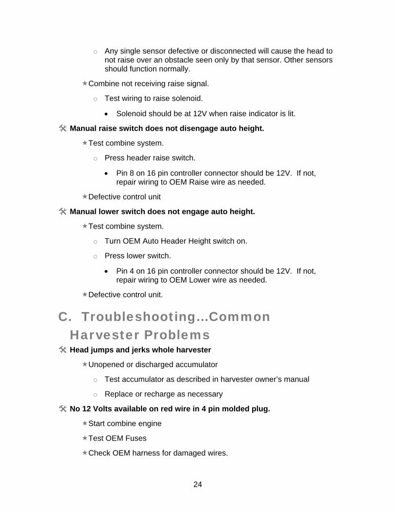
o Any single sensor defective or disconnected will cause the head to not raise over an obstacle seen only by that sensor. Other sensors should function normally.
Combine not receiving raise signal.
o Test wiring to raise solenoid.
Solenoid should be at 12V when raise indicator is lit.
Manual raise switch does not disengage auto height.
Test combine system.
o Press header raise switch.
Pin 8 on 16 pin controller connector should be 12V. If not, repair wiring to OEM Raise wire as needed.
Defective control unit
Manual lower switch does not engage auto height.
Test combine system.
o Turn OEM Auto Header Height switch on.
o Press lower switch.
Pin 4 on 16 pin controller connector should be 12V. If not, repair wiring to OEM Lower wire as needed.
Defective control unit.
C. Troubleshooting…Common Harvester Problems
Head jumps and jerks whole harvester
Unopened or discharged accumulator
o Test accumulator as described in harvester owner’s manual
o Replace or recharge as necessary
No 12 Volts available on red wire in 4 pin molded plug.
Start combine engine
Test OEM Fuses
Check OEM harness for damaged wires.
25
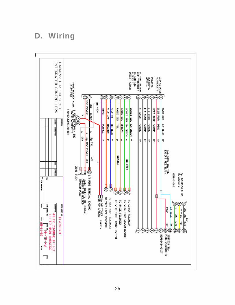
D. Wiring
26
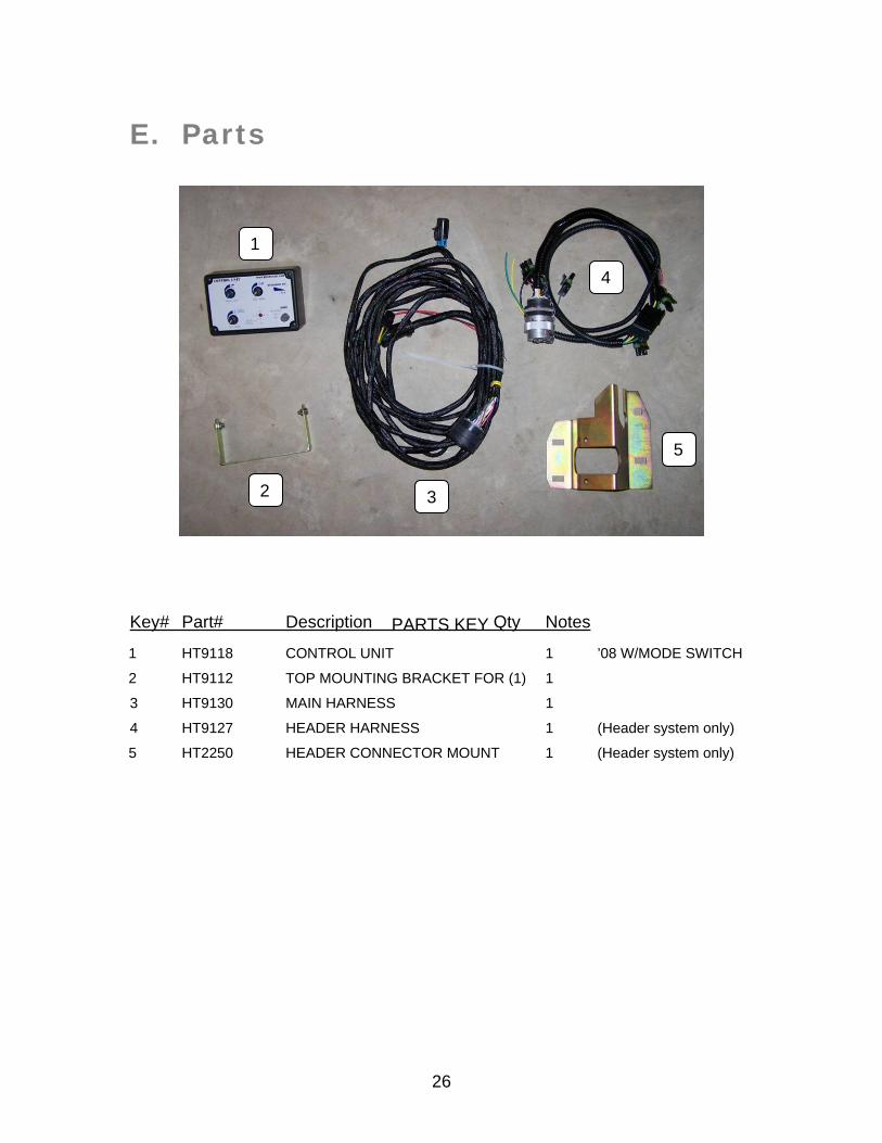
E. Parts
Key# Part# Description Qty Notes 1 HT9118 CONTROL UNIT 1 ’08 W/MODE SWITCH
2 HT9112 TOP MOUNTING BRACKET FOR (1) 1
3 HT9130 MAIN HARNESS 1
4 HT9127 HEADER HARNESS 1 (Header system only)
5 HT2250 HEADER CONNECTOR MOUNT 1 (Header system only)
PARTS KEY
1
2
5
3
4
27
F. Warranty Information Statement of Limited Warranty for Corn Products
Headsight Inc. (Headsight) warrants its new corn sensors assemblies for a period of thirty-six (36) months, and its electronic wiring and interface control boxes for a period of twelve (12) to be free from defects in material and workmanship following the date of purchase by the retail purchaser. Headsight warrants genuine Headsight replacement parts and components to be free from defects in material and workmanship for a period of six (6) consecutive months following the date of purchase or the remainder of the original equipment warranty period, whichever is longer. Headsight’s obligation under these warranties shall be limited to repairing or replacing, free of charge to the original purchaser, any part that, in Headsight’s judgment, shows evidence of such defect.
Limitations to Warranty This warranty does not cover: o Warranty claims directly resulting from improper installation of the product. o Any product damaged by accident, abuse, misuse, or negligence after shipment from Headsight. o Any unauthorized product alteration or modification. o Any unauthorized repairs made with parts other than genuine Headsight parts. o Any repairs performed by anyone other than Headsight or an authorized Headsight dealer unless
specifically authorized by Headsight.
Warranty Procedure o Troubleshooting must be done between customer and Headsight through Headsight’s technical
assistance @ 574.220.5511. o Labor reimbursement will occur only pre-arranged through Headsight technical assistance and be
scheduled to a flat rate basis or reasonable time allowance in Headsight’s judgment. o There is no mileage reimbursement. o Diagnostic time will not be reimbursed except in pre-arranged circumstances. o Warranty claims should be on typical dealer service work order with a number and name to be attached
for any future correspondence. o All warranty work must be performed, and claims submitted, within sixty (60) days of the occurrence of
the claim and within the warranty period. o All parts removed during warranty repair should be held for a period of 60 days after the warranty claim
has been submitted to Headsight. o Headsight, Inc. reserves the right to either inspect the product at the original retail purchaser’s location
or require it to be returned to Headsight, Inc. for inspection.
Limitation of Liability Headsight makes no express warranties other than those, which are specifically described herein. Any description of the goods sold hereunder, including any reference to buyer’s specifications and any descriptions in circulars and other written material published by Headsight is for the sole purpose of identifying such foods and shall not create an express warranty that the goods shall conform to such description. THIS WARRANTY IS EXPRESSLY IN LIEU OF ALL OTHER WARRANTIES EXPRESSED OR IMPLIED. There are no implied warranties of merchantability or fitness of a particular purpose. This warranty states Headsight’s entire and exclusive liability and buyer’s exclusive remedy or any claim for damages in connection with the sale of furnishing of Headsight products, their design, suitability for use, installation or operation, or for any claimed defects herein. HEADSIGHT WILL IN NO EVENT BE LIABLE FOR ANY INCIDENTAL OR CONSEQUENTIAL DAMAGES WHATSOEVER, NO FOR ANY SUM IN EXCESS OF THE PRICE RECEIVED FOR THE GOODS FOR WHICH LIABILITY IS CLAIMED. No representative of Headsight nor any dealer associated with Headsight has the authority to change the items of this warranty in any manner whatsoever, and no assistance to purchaser by Headsight in the repair of operation of any Headsight product shall constitute a waiver of the conditions of this warranty, nor shall such assistance extend or revive it. Headsight reserves the right to make improvements in design or changes in specifications at any time, without incurring any obligation to owners of units previously sold. Warranty: 1/2007

28