Embed Size (px)
Citation preview
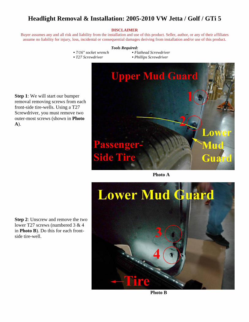
Headlight Removal & Installation: 2005-2010 VW Jetta / Golf / GTi 5
DISCLAIMER
Buyer assumes any and all risk and liability from the installation and use of this product. Seller, author, or any of their affiliates
assume no liability for injury, loss, incidental or consequential damages deriving from installation and/or use of this product.
Tools Required:
• 7/16" socket wrench • Flathead Screwdriver
• T27 Screwdriver • Phillips Screwdriver
Step 1: We will start our bumper
removal removing screws from each
front-side tire-wells. Using a T27
Screwdriver, you must remove two
outer-most screws (shown in Photo
A).
Photo A
Step 2: Unscrew and remove the two
lower T27 screws (numbered 3 & 4
in Photo B). Do this for each front-
side tire-well.
Photo B
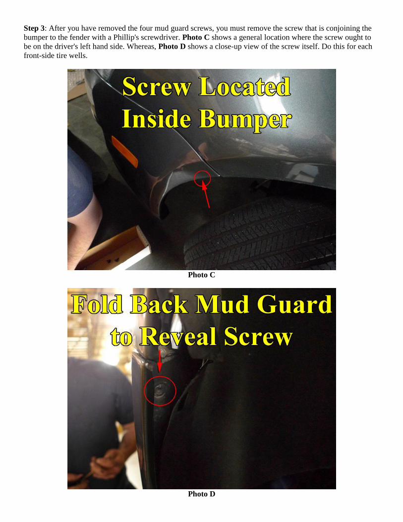
Step 3: After you have removed the four mud guard screws, you must remove the screw that is conjoining the
bumper to the fender with a Phillip's screwdriver. Photo C shows a general location where the screw ought to
be on the driver's left hand side. Whereas, Photo D shows a close-up view of the screw itself. Do this for each
front-side tire wells.
Photo C
Photo D
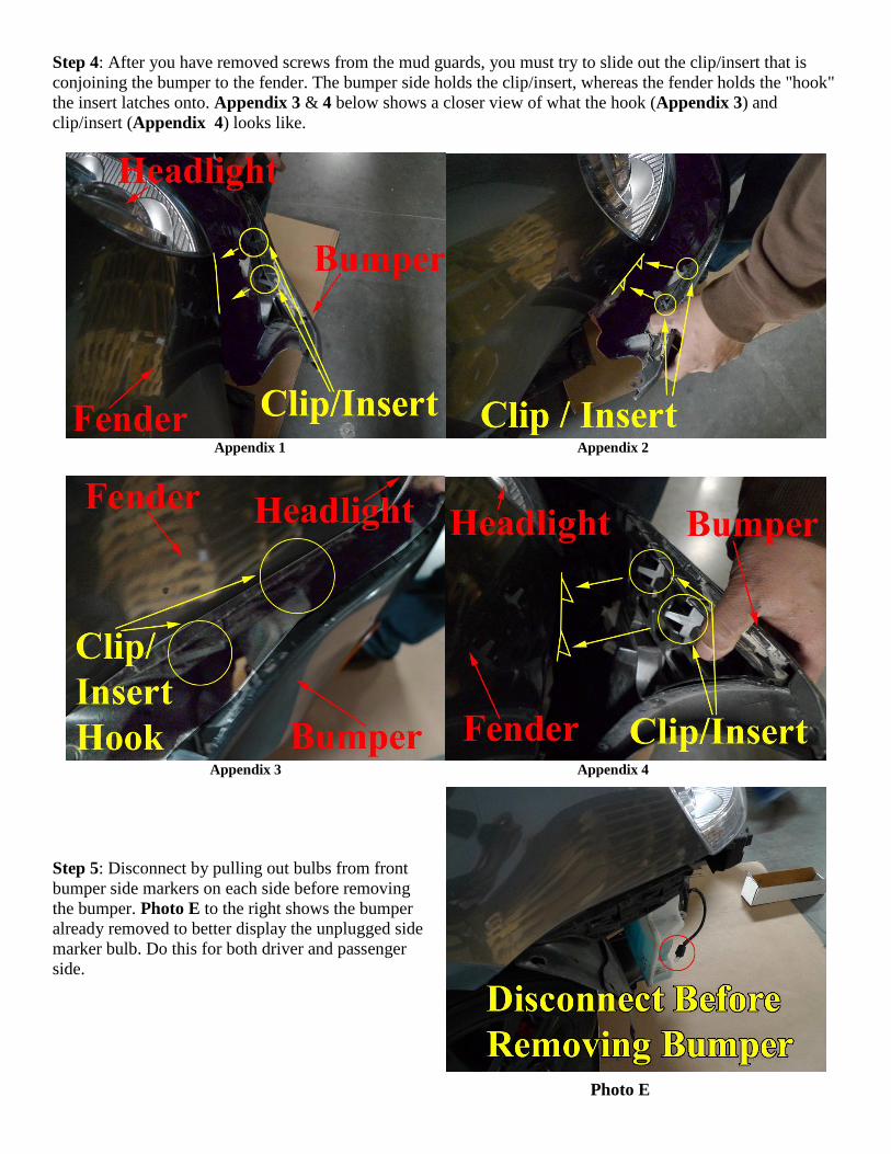
Step 4: After you have removed screws from the mud guards, you must try to slide out the clip/insert that is
conjoining the bumper to the fender. The bumper side holds the clip/insert, whereas the fender holds the "hook"
the insert latches onto. Appendix 3 & 4 below shows a closer view of what the hook (Appendix 3) and
clip/insert (Appendix 4) looks like.
Appendix 1 Appendix 2
Appendix 3 Appendix 4
Step 5: Disconnect by pulling out bulbs from front
bumper side markers on each side before removing
the bumper. Photo E to the right shows the bumper
already removed to better display the unplugged side
marker bulb. Do this for both driver and passenger
side.
Photo E
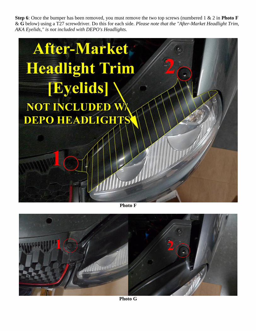
Step 6: Once the bumper has been removed, you must remove the two top screws (numbered 1 & 2 in Photo F
& G below) using a T27 screwdriver. Do this for each side. Please note that the "After-Market Headlight Trim,
AKA Eyelids," is not included with DEPO's Headlights.
Photo F
Photo G
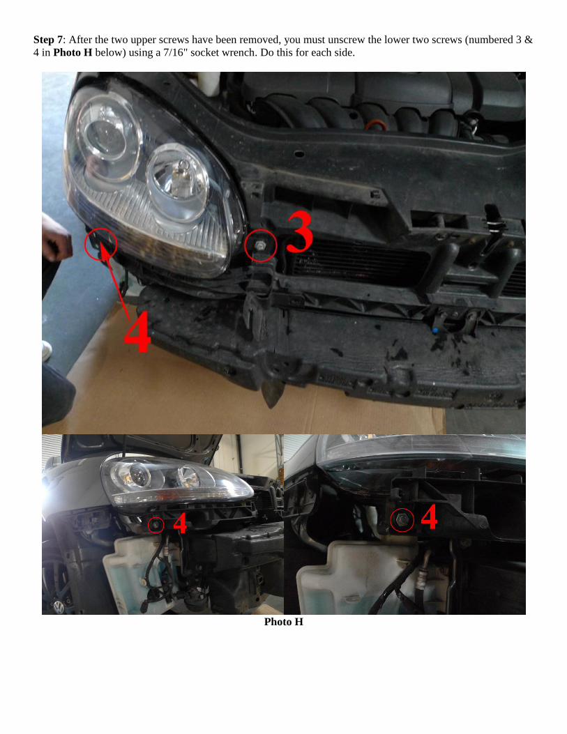
Step 7: After the two upper screws have been removed, you must unscrew the lower two screws (numbered 3 &
4 in Photo H below) using a 7/16" socket wrench. Do this for each side.
Photo H
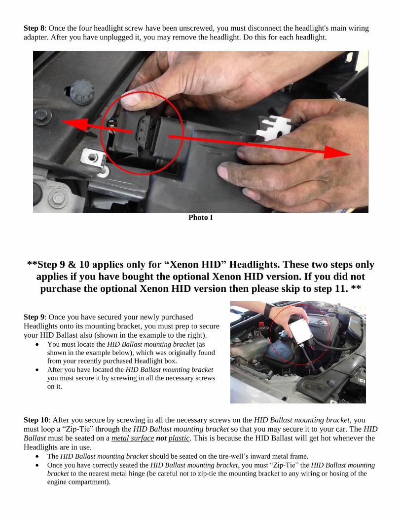
Step 8: Once the four headlight screw have been unscrewed, you must disconnect the headlight's main wiring
adapter. After you have unplugged it, you may remove the headlight. Do this for each headlight.
Photo I
**Step 9 & 10 applies only for “Xenon HID” Headlights. These two steps only
applies if you have bought the optional Xenon HID version. If you did not
purchase the optional Xenon HID version then please skip to step 11. **
Step 9: Once you have secured your newly purchased
Headlights onto its mounting bracket, you must prep to secure
your HID Ballast also (shown in the example to the right).
You must locate the HID Ballast mounting bracket (as
shown in the example below), which was originally found
from your recently purchased Headlight box.
After you have located the HID Ballast mounting bracket
you must secure it by screwing in all the necessary screws
on it.
Step 10: After you secure by screwing in all the necessary screws on the HID Ballast mounting bracket, you
must loop a “Zip-Tie” through the HID Ballast mounting bracket so that you may secure it to your car. The HID
Ballast must be seated on a metal surface not plastic. This is because the HID Ballast will get hot whenever the
Headlights are in use.
The HID Ballast mounting bracket should be seated on the tire-well’s inward metal frame.
Once you have correctly seated the HID Ballast mounting bracket, you must “Zip-Tie” the HID Ballast mounting
bracket to the nearest metal hinge (be careful not to zip-tie the mounting bracket to any wiring or hosing of the
engine compartment).
After you have completed securing your HID Ballast mounting bracket, you may cut any excess Zip-Tie that is
protruding out of the engine compartment.
Repeat Step 10 for both sets of HID Ballast mounting bracket on each side.
=========================END of Xenon HID Part of Installation========================
Step 11: Once you have removed your Headlights, you may back-track Steps 8 to Step 1 for the reinstallation of
your newly purchased Headlights.
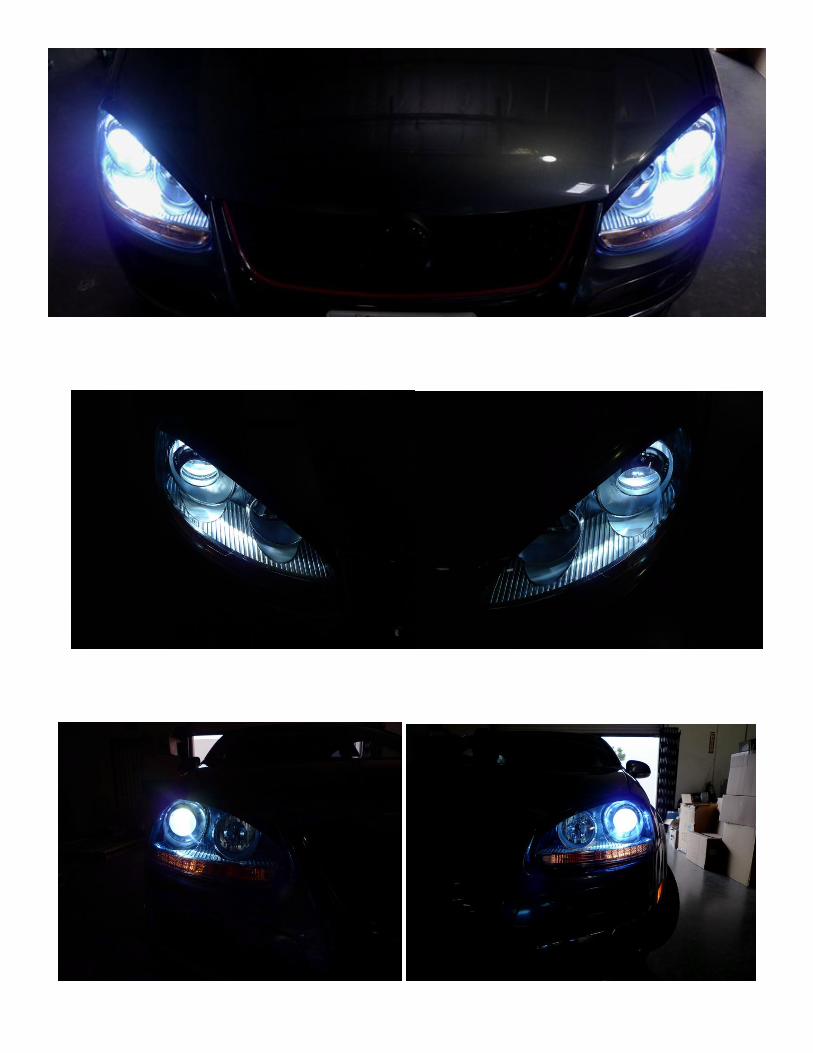
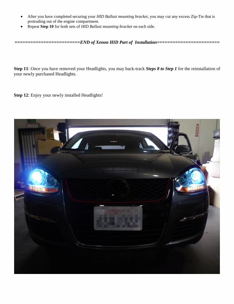
Step 12: Enjoy your newly installed Headlights!