Embed Size (px)
DESCRIPTION
Tunnelling and Tunnel Mechanics
Citation preview
4
Heading
The heading of a tunnel comprises the following actions: excavation, supportof the cavity and removal of the excavated earth (mucking). It is distinguishedbetween conventional (also called incremental or cyclic) heading and continu-ous heading. This chapter introduces the several methods applied. A rigorousclassification is difficult, as these methods are often combined. It has becomeusual to distinguish between conventional (or incremental) heading on theone hand and continuous (or TBM) heading on the other hand. This is, how-ever, not reasonable: also TBM-heading consists of several steps and is, thus,incremental (cf. Sections 4.2 and 4.4.4).The main characteristic of conventional heading is that it proceeds in smalladvance steps, whose length ranges between 0.5 and 1.0m in soft ground.This length is an important design parameter, as the freshly excavated spacehas to remain stable for a while (at least 90 minutes) until the support hasbeen installed. The length of advance steps influences also the settlement ofthe ground surface: reducing the advance length decreases considerably thesurface settlement.
4.1 Full face and partial face excavation
Large cavities are less stable than small ones (cf. Section 16.3). Therefore, inmany cases the tunnel cross section is not excavated at once, but in parts.For cross sections > 30-50 m2 in weak rock the face must be supported (witha heap of soil, shotcrete, nails) or excavated in parts. In the early era oftunnelling many different schemes of partial face excavation were developed.The terminology is neither unique nor systematic. To give examples, the core-heading (Kernbauweise) and the Old Austrian Tunnelling Method could bementioned. Such partial excavation methods were developed when supportwas made with timbering and masonry. In contrast, contemporary support isaccomplished with steel and sprayed concrete.The various types of partial face excavations are:

76 4 Heading
Core heading: This is also known as the German heading method (althoughit was first used in France). It consists of excavating and supporting firstthe side and top parts of the cross section and subsequently the centralpart (core). The ring closure at the invert comes at the end. The firstgallery also serves for exploration. The crown arch is founded on the sidegalleries thereby keeping the related settlements small.
Old Austrian Tunnelling Method: This method is schematically repre-sented in Figure 4.1. Its characteristic feature is the crown slot. The si-multaneous work in several excavation faces allows a fast advance. E.g.,the old Arlberg (rail) tunnel was built with the Old Austrian TunnellingMethod. Its construction time was comparable to the one of the newArlberg (road) tunnel, which has roughly the same length and was builtca 100 years later.
Fig. 4.1. Excavation sequences of the Old Austrian Method
Nowadays the most widespread methods of partial face excavation are(i) top heading and (ii) sidewall drift. Variants are shown in Fig. 4.2
Top heading: The crown is excavated before the bench (Fig. 4.4, 4.5). Thetemporary support of the crown with shotcrete can be conceived as a sortof arch bridge (Fig. 4.6). This explains why the abutments are prone tosettlements, which induce settlements of the ground surface. Countermea-sures are to enlarge the abutments (so-called elephant feet), to strengthenthem with micropiles or the construction of a temporary invert. The lattermust be constructed soon after the heading of the crown, i.e. not more
2Wu, W. and Rooney, P.O., The role of numerical analysis in tunnel design. In:Tunneling Mechanics (edited by D. Kolymbas), 87-168, Logos, Berlin, 2002

4.1 Full face and partial face excavation 77
Fig. 4.2. Several types of partial face excavation2. The depicted parts of the crosssection are driven and supported consecutively.
than 2 to 5 advance steps beyond it.3 A soon construction of a temporaryinvert of the crown section or, better, the soon excavation and support ofthe bench and invert helps avoiding large settlements of the abutments ofthe crown arch. This means that the length a = a1 + a2 (Fig. 4.5) shouldbe kept as small as possible. On the other hand, a1 should be sufficientlylarge to enable efficient excavation and support works in the crown.If the crown and the bench are excavated simultaneously, then the rampmust be ’continuously’ moved forward (i.e. every now and then). Alterna-tively, the ramp is not placed at the centre (as shown in Fig. 4.5) but onthe side of the bench. Then, the other side of the bench can be excavatedover a longer distance. If the excavation of a ramp may cause instabil-ity, then the ramp must be heaped up after excavation and support of thebench. In 1985 a collapse occurred during the heading of the Kaiserau tun-nel in Germany.2 It was caused by a slit which was made to construct theramp and which rendered the temporary invert of the calotte ineffective(Fig. 4.3).
Sidewall drift: The side galleries are excavated and supported first. Theyserve as abutment for the support of the crown, which is subsequentlyexcavated (Fig. 4.7 and 4.10). This type of heading is approx. 50%more expensive and slower than top heading. Therefore it is preferred
3Richtlinien und Vorschriften fur den Straßenbau (RVS9.32)4Tunnelling Switzerland, K. Kovari & F. Descoeudres (eds.), Swiss Tunnelling
Society, 2001, ISBN 3-9803390-6-8

78 4 Heading
Fig. 4.3. The slit in the temporary lining caused collapse in the Kaiserau tunnel
Fig. 4.4. Top heading, cross and longitudinal sections. 1: calotte, 2: bench
Fig. 4.5. Schematic representation of top heading

4.1 Full face and partial face excavation 79
Fig. 4.6. Concept to explain the support of crown. The excavation support actsin a similar way as an arch of a masonry bridge. The weight of the overburden isconcentrated in the tow abutments.
Fig. 4.7. left: core heading, right: sidewall drift
in soils/rocks of low strength. Note that a change from top heading tosidewall drift is difficult to accomplish.
In all types of partial excavation attention should be paid to the connections ofthe lining segments constructed at different steps. The final lining (includingits reinforcement) should be continuous without any weak points (interrup-tions or slits). Considering e.g. the connection of the elephant foot with thetemporary invert, the following method can be applied. The reinforcement(wire mesh or rebars) to provide the connection with the bench lining (to beplaced later) protrudes from the elephant foot and is folded within a protectivesand bed below the temporary invert (Fig. 4.9). The subsequent demolitionof the temporary invert and the further excavation should be executed withcaution, so that this wire mesh is not damaged.
5Tunnel, 9, 2/2000, p. 19

80 4 Heading
Fig. 4.8. Sidewall drift4
Fig. 4.9. Construction detail of the reinforcement at the connection of the elephantfoot with the temporary invert
4.2 Excavation
Excavation is the process of detaching the rock using the following methodsand tools:
Hammer: Pneumatic and hydraulic hammers can be applied in weak rocksand achieve performances comparable with drill & blast (see later in thissection). In addition, they avoid the vibrations caused by drill & blast.E.g., the hydraulic hammer HM 2500 of Krupp Berco has the followingexcavation performance:
6Krupp Berco

4.2 Excavation 81
Fig. 4.10. Niedernhausen tunnel, sidewall drift5
Fig. 4.11. Hydraulic hammer6

82 4 Heading
Unconfined strength of the rock Excavation capacity(MPa) (m3/h)40-50 4070-80 2680-100 20
These performances can be improved by loosening blasts. Hydraulic ham-mers are carried by wheel or track vehicles. Dust is treated (not completelysuccessfully) with spraying water from nozzles or water-hoses.
Excavators: Boomed backhoe buckets excavate weak rock, while thin rip-pers and hydraulic chisels are applied whenever hard rock inclusions areencountered. In order to exactly follow the prescribed tunnel profile thesetools must be sufficiently free to rotate. Excavators can exhibit a highperformance if the strength of the rock is moderate, i.e. if the rock is ei-ther soft or jointed (RMR< 30). Ripping is applied for a RMR between 30and 60. Another criterion for the applicability of ripping is a propagationvelocity of P-waves between 1 and 2 km/s.
Roadheaders (boom cutters): These tools are used for moderate rockstrengths and for laminated or joined rock. The cutter is mounted onan extension arm (boom) of the excavator and millcuts the rock intosmall pieces. Thus, overprofiling can be limited and also the loosening ofthe surrounding rock is widely avoided. One has to provide for measuresagainst dust (suction or water spraying). The required power of the motorsincreases with rock strength.
Fig. 4.12. Excavator7(left); Roadheader8(right)
Tunnel boring machines (TBM): TBMs are applicable to rock of mediumto high strength (50 < qu < 300 MN/m2) if its abrasivity is not too high.TBMs excavate circular cross sections with a rotating cutterhead equippedwith disc cutters. To press the cutterhead against the rock, the TBM is
7Liebherr 9328Voest Alpine AM 100

4.2 Excavation 83
propped at the tunnel wall by means of extendable grippers. Therefore,the rock must have a sufficient strength.The support can be installed soon after the excavation. The classifica-tion of TBM as ’continuous’ heading instead of ’incremental’ (also called’cyclic’) is misleading, because a TBM advances in strokes. Regular stopsare needed, mainly for the maintenance of the excavation tools.The design of a TBM comprises determination of thrust, torque, size andspacing of discs. The advance rate (m/h) is given by the product penetra-tion rate (m/h)×TBM utilisation (%).Since the TBM fills up the excavated space more or less completely, thesystematic support can only be installed beyond it (i.e. beyond a workingspace of ca 10 to 15 m length). In weak rock, however, support measuressuch as rock bolts (Fig. 4.13 left) and wire meshes (Fig. 4.13 right) haveto be applied adjacent to the cutterhead.The minimum curvature radius is 40 - 80 m, with back-up equipment theminimum radius is 150 - 450 m.TBMs are often protected against cave-ins by cylindrical steel shields.Therefore, more details on TBMs are given in Section 4.4, whereas the rockexcavation by means of rotating cutterheads is described in Section 4.6.2.
Fig. 4.13. left: Anchoring behind the cutterhead; right: Installation of wire meshbehind the cutterhead10
10Herrenknecht AG

84 4 Heading
Drill & blast: Drill & blast was first applied in 1627 by the Tyrolean Kas-
par Weindl in a silver mine in Banska Stiavnica (former Schemmnitz,Slovakia). It is suitable for hard rock (e.g. granite, gneis, basalt, quartz)as well as for soft rock (e.g. marl, loam, clay, chalk). Thus, it is applicablefor rocks with varying properties. Moreover, drill & blast is advantageousfor:• relatively short tunnels, where a TBM does not pay• very hard rock• non-circular cross sections.To keep drill & blast economical, the involved steps (drilling, charging,tamping, igniting, ventilating, support) must be coordinated in such away that downtimes are avoided. The most time-consuming operationsare drilling and charging.More details on drill & blast excavation are presented in the next section.
Fig. 4.14. Gripper TBM12; 1 Shield, 2 arch segments, 3 annular errector, 4 drillingequipment for rock bolting, 5 protection canopy, 6 protection girder, 7 grippers
4.3 Drill & blast
The drill & blast method consists of several subsequent steps (drilling, charg-ing, tamping, ignition, extraction of fumes by ventilation, mucking, support),which will be described subsequently.
12Brochure Herrenknecht TBM

4.3 Drill & blast 85
4.3.1 Drilling of blastholes
Rotary and percussion drilling is applied to drive blastholes within a diameterrange from 17 to 127 mm (mostly being ca 40 mm) with drilling rates of up to3 m/min into the rock. The prescribed positions, orientations and lengths ofblastholes must be kept precisely, therefore the drilling equipment is mountedon tire carriages, called jumbos, with 2 - 6 booms (Fig. 4.15). The lengthof the blastholes corresponds to the advance step (usually 1-3 m). To achievegood blast results, the advance step should not exceed the minimum curvatureradius of the tunnel cross section (for parallel cut — see section 4.3.5 — theadvance step can be longer).
Fig. 4.15. Jumbo (also called ’boomer’)13
Influence from initialposition of drilling rod
Intended borehole
Derivation due to wrongposition of the boom
Deviationdue to rockstructure
Fig. 4.16. Advance drilling. Intended and real borehole positions.
13Hydralift

86 4 Heading
4.3.2 Charging
Lengthy charges are applied in tunnelling. Charging depends on the typeof explosive. Cartridges are pushed with the help of rods, powders (such as“ANFO”, a mixture of ammonium nitrate and fuel oil) and emulsions are castor pumped in into the boreholes.
4.3.3 Tamping
Explosion is the ’instantaneous’ transformation of the solid (or fluid) explosiveinto a mixture of gases called fume (see Appendix A). To achieve pounding,the fume must be contained, i.e. its expansion must be hindered. This iswhy blastholes are tamped, i.e. plugged. Since the impact of the fume issupersonic, the strength of the plug is immaterial. Thus, a sufficient tampingis obtained with sand or water cartridges. In long blastholes even the inertiaof the air column provides a sufficient tamping. Tamping increases poundingof the rock and reduces the amount of toxic blast fumes by improving thechemical transformation of the charge. Tamping, in particular with water, isalso a countermeasure against dust production.
4.3.4 Ignition
Detonation is oxidation, where oxygen is present in compound form withinthe explosive. The reaction front propagates within the explosive with a det-onation velocity which amounts up to 8 km/s and depends on the chemicalcomposition, size, containment and age of the explosive. The detonation frontleaves behind the fume, which is a highly compressed gas mixture. 1 kg ex-plosive produces gas volume of nearly 1 m3 under atmospheric pressure. Thehighly compressed fume exerts a large pressure upon its containment. Theenergy content of an explosive is not overly high, but the rate at which thisenergy is released corresponds to a tremendous power. Modern explosives areinert against hits, friction and heat. They can only be ignited with a (smaller)initial explosion. Therefore, ignition occurs through
Electric detonators: These consist of a primary charge, which is susceptibleagainst heat, and a less susceptible secondary one. The primary chargeis ignited by means of an electric glow wire. A retarding agent can beadded in such way that the explosion is released some miliseconds afterclosing the circuit. The detonators are placed in the bottom of the blast-holes. Electronic detonators have a higher retardation accuracy (which isimportant for smooth blasting) and can be ignited with a coded signal.
Detonating cords: These cords (∅ 5 to 14mm) have a core made of ex-plosive and are ignited with an electric detonator. The detonation propa-gates along the cord with a velocity of approx. 6.8 km/s. Modern variants(“Nonel”, “Shockstar”) are synthetic flexible tubes, whose inner walls are

4.3 Drill & blast 87
coated with 10-100 g/m explosive (Nitropenta). Detonating cords allowbunched ignitions with only one electric detonator.
The power of detonators reduces with time, but appropriate storage ensuresa long life.
Fig. 4.17. Detonators
4.3.5 Distribution of charges and consecution of ignition
The explosion aims at (i) breaking the rock into pieces which are manageablefor haulage, (ii) avoiding overbreak or insufficient excavation profile (so-calledsmooth blasting) and (iii) not disturbing the surrounding rock. To this end,several schemes (drilling and ignition patterns) have been empirically devel-oped for the distribution of charges and the consecution of ignition. It isdistinguished between production and contour drillholes. The most efficientexcavation is obtained if the fume pushes the rock against a free surface. Thiscan be achieved e.g. with a V-cut (’edge’ or ’fan’ cut)14: The blastholes inthe central part of the face are conically arranged and ignited first (Fig. 4.18).The surrounding blastholes are ignited consecutively with a delay of some mil-liseconds. Thus the rock is progressively pared, from the cut to the contour.Parallel blastholes (’parallel cut’) are easier to drill precisely and enable longeradvance steps but require more explosive than conically arranged ones (V-cut).Several unloaded drillholes are provided in the parallel cut, creating thus acavity against which the detonation pushes the rock. Thus the efficiency is
14J. Johansen, Modern Trends in Tunneling and Blast Design, Balkema, 2000

88 4 Heading
contour blastholes
Fig. 4.18. Wedge cut (left), distribution of blast holes (right)
increased. For smooth blasting, the contour holes have a small spacing (e.g. 40-50 mm) and are charged with detonating cords (Fig. 4.19). Smooth blastinghelps to minimize the costly after-treatment (post-profiling).
Fig. 4.19. Charging of contour blastholes (left), rock surface after the detonation(right)
In case of anisotropic, jointed or stratified rock, the distribution of blastholesand the ignition pattern have to be adapted to the structure of the rock.The various work steps for drill & blast are repeated cyclically. Adjustingand optimization of the blasting scheme with regard to the individual rockproperties are therefore recommended. This can be accomplished by the aidof computers.15
4.3.6 Explosives
There are several types of explosives. Explosive gelatines like Ammongeliteor Gelamon are plastic, have a high strength and develop large gas volume(approx. 800 l/kg). They are water resistant and allow safe handling. Thedetonation speed is 6.5 km/s.
15“Computerised drill & blast tunnelling”, Tunnels & Tunnelling, July 1995, 29-30, and G. Girmscheid “Tunnelbau im Sprengvortrieb – Rationalisierung durch Teil-robotisierung und Innovation”, Bautechnik 75 (1998), 11-27

4.3 Drill & blast 89
In explosive emulsions, oil serves as the combustible agent. Oxygen is deliveredfrom salt (nitrate) solutions available within droplets of 10−6 m diameter.These droplets are covered with a 10−9 m thick oil film. They develop a gasvolume of 1,000 l/kg and a detonation speed of 5.7 km/s. They are waterresistant, safe in handling, and can be pumped into the blastholes or placedwithin cartridges. The non-explosive components are separately delivered tothe construction site, where they are mixed together. Compared with explosivegelatines, the strength of explosive emulsions is reduced and, therefore, ca 10%more blastholes are needed. On the other hand, their fumes are less toxic(having, though, a pronounced smell of ammonia), so a shorter ventilation isneeded and the spoil is less contaminated.Explosive powders are also safe but not water resistant. With a gas volumeof 1,000 l/kg and a low detonation speed of approx. 3 km/s they push ratherthan shatter the rock.A recent development are the so-called non-explosive explosives like BRISTARor CALMMITE. These are expansive cements. Mixed with water and cast intoboreholes they expand, thus developing pressures up to 600 bar and tearingup the surrounding rock.
Fig. 4.20. Explosive catridges
4.3.7 Explosive consumption
Explosives are an important cost issue. The required amount of explosivesincreases with decreasing tunnel cross section and increasing rock strength. Itranges between 0.3 and 4.5 kg/m3.
4.3.8 Safety provisions
Only licensed individuals are allowed to handle explosives. Receipt, consump-tion and return of explosives must be registered in a tractable way. Transporta-

90 4 Heading
tion must conform the regulations for transportation of dangerous materials.16
The electric circuit for ignition should be checked. The blasted rock can bespread over large distances. Therefore a safety distance of 200 to 300 m off theface should be maintained. The removal of non exploded charges is particu-larly difficult. Sometimes the tamping can be extracted and a new detonatorbe placed. Another method is to overlay a new charge and let it explodetogether with the old one.Electromagnetic fields (e.g. radio-frequency radiation from mobile telephones)may cause inadvertent initiation of electro-explosive devices. Therefore, a safedistance must be kept from radiation sources.17
4.3.9 Ventilation
Contemporary explosives have a positive oxygen balance but still do containtoxic gases such as CO2,CO and nitrogen oxids. Also dust is dangerous, inparticular quartz dust. Therefore, following an explosion, work should onlybe resumed after a ventilation time of at least 15 minutes with an air velocity(averaged over the largest cross section) of at least 0.3 m/s. During ventilation,the personnel should stay either in the open air or within a fume protectioncontainer. This is also advisable because parts of the shotcrete lining can bedetached (due to the explosion shock) and fall down.
4.3.10 Backup
A new development is the hanging backup system as applied in the Loetschbergbase tunnel (Fig. 4.21). Rockbolts are used to mount two overhead rails onwhich the backup runs. The benefits are faster production, greater safety, freeaccess to the face, easier construction of invert and cross-passages.18
4.3.11 Shocks and Vibrations
Vibrations due to drill & blast (as well as due to TBM)19 propagate in the un-derground as elastic waves and can affect constructions and human well-being.The disturbance is controlled (for frequencies > 10 Hz)20 by the maximumvibration velocity, which can be measured by means of so-called geophones.Some typical values of vmax are shown in Table 4.1.
16www.sprenginfo.com17P. Roh, Beeinflussung elektrischer Zundanlagen durch mobile und stationare
Funkeinrichtungen. Nobelhefte 2002, 5-1418M. Knights, P. Hoyland, Policies and projects - Swiss style, Tunnels & Tun-
nelling International, April 2002, 28-3119R.F. Flanagan: Ground vibration from TBMs and shields, Tunnels & Tun-
nelling, Vol. 25, No. 10,1993, 30-33. J. Verspohl: Vibrations on buildings caused bytunnelling, Tunnels & Tunnelling, 1995, BAUMA Special Issue, 81-85
20Values of the peak velocity for domestic structures exposed to transient vibra-tion can be seen in Tunnels & Tunnelling International, June 2002, 31-33

4.3 Drill & blast 91
Fig. 4.21. Hanging backup system in drill & blast heading in the Loetschberg basetunnel (perspex model).
vmax in mm/s
distanceSource
5 m 10 m 25 m
Hydraulic-hammer 1.7 0.6 0.1
truck 3.0 1.1 0.3
large bulldozer 3.9 1.4 0.3
TBM (hard rock) 5.5 2.2 0.6
vibrated pile 30 12 2.8
Table 4.1. Typical values of vmax
Rating criteria for disturbance and hazard due to vibrations can be foundin standards such as DIN 4150 and ONORM S 9020. Transient vibrations(e.g. due to drill & blast) can be noticed from vmax = 0.5 mm/s and causecomplaints from vmax = 5 mm/s. Humans are particularly susceptible and lesstolerant of continued vibrations, especially during the night. Vibration hazardis usually over-rated and this may cause pre-existing fissures in buildings tobe attributed to drill & blast. Therefore, residents in the neighborhood shouldbe informed about possible hazards. In addition, a perpetuation of evidenceshould be carried out. Vibrations due to drill & blast can be reduced by split-ting the explosion into several smaller explosions with a consecution of somemiliseconds. E.g., Nonel detonators enable 25 explosions within 6 seconds.21
TBM vibrations are usually not noticeable at distances greater than 45 m.
21Tunnels & Tunnelling, July 1995, p. 8

92 4 Heading
4.4 Shield heading
Shields are used for heading in weak rocks and soil.22 The shield is a steeltube with a (usually) circular cross section (Fig. 4.22 and 4.23). Its front isequiped with cutters. The shield is pushed forward into the ground by meansof jacks. A so-called blade shield is equipped with blades that can be protrudedseparately (Fig. 4.24).
Fig. 4.22. Modern shield heading23
Jacks: The jacks have a stroke between 0.8 and 1.5 m, they operate withpressures up to 400 bar and apply forces up to 3 MN. Their abutment isthe already installed lining. The shield can be steered by applying differentpressures to the jacks distributed along its circumference. On this, shields
22see also B. Maidl, M. Herrenknecht , L. Anheuser, Maschineller Tunnelbau imSchildvortrieb, Ernst & Sohn Verlag, Berlin 1995; M. Kretschmer und E. Fliegner,Unterwassertunnel, Ernst & Sohn Verlag, Berlin 1987
23Tunnelling Switzerland, K. Kovari & F. Descoeudres (eds.), Swiss TunnellingSociety, 2001, ISBN 3-9803390-6-8

4.4 Shield heading 93
should be not too lengthy (L < 0.8 D) and the cavity diameter should beslightly larger than the outer diameter of the shield, i.e. a shield-to-rock-clearance of ca 25 mm should be provided for.
Fig. 4.23. Historic shield tunnelling beneath the St. Clair River
Fig. 4.24. Shield with blades and roadheader24
After each advance stroke the hydraulic pistons of the jacks are retractedin such a way that an additional slice of lining can be added under theprotection of the shield tail (Fig. 4.25). During the subsequent advance
24Herrenknecht

94 4 Heading
Fig. 4.25. Sequences of shield heading
stroke the tail gap is filled with grout. Coordination of the individual stepsis important. Typical advance rates are 0.5 to 2 m/h.An overly large thrust can damage the lining segments. The thrust isapplied to overcome mainly the wall friction, which can be estimated byμσUL, where L and U are the length and the circumference of the shield,respectively. The normal stress σ is taken simply as the effective verticalstress at the depth of the tunnel axis and the friction coefficient μ is usuallyassumed between 0.7 and 0.9. If the face is supported by breasting flaps(Fig. 4.26 right), a force of 8 to 10 MN has to be added.
Fig. 4.26. Platform-shield25 ; shield with face breasting flaps26
Excavation: The excavation is either full-face, with rotary cutterheads (Fig. 4.27),or selective, with boom headers or roadcutters (roadheaders) that excavatethe face in a series of sweeps (see also Section 4.2). The cutterhead can
25Les Vignes-Tunnel, Herrenknecht26Wayss & Freytag

4.4 Shield heading 95
be driven either electrically or hydraulically. Electric drive has a higherefficiency but is more difficult to control. Hydraulic drive is more flexible.The necessary thrust and torque are determined empirically. Note, how-ever, that in general the cutterhead is not expected to support the face.At standstill the openings should be closed with panels. In sticky soils thewheel should be as open as possible. Adhesion of sticky soil (e.g. plasticclay) is a considerable handicap and can be combated with flushing.The cutterhead is equipped with the following tools to excavate theground:• disc cutters, drag bits (for rock and embedded blocks)• chisels, scrapers (for sand and gravel)• scrapers (for cohesive soil)
Fig. 4.27. Cutterheads with scrapers and discs
Some maintenace works to the cutterhead can only be undertaken fromahead. To this end, the adjacent soil can be stabilised by grouting orfreezing. Then the shield is retracted so that a space is created from whichthe inspection can proceed.Cutterheads also have facilities for advance drilling that serves either forsoil exploration or for grouting. The Herrenknecht cutterhead utilized inthe 4th Elbe tube and later in Moscow (Lefortovo), see Fig. 4.27 (right),was equipped by Amberg with a device to detect blocks and other obsta-cles with sonic pulses.
Face support: An unstable face can cause surface settlements and should,therefore, be supported e.g. with panels (Fig. 4.26 right) or with the cut-terhead (if 5 < cu < 30 kN/m2). Alternatively, the soil is allowed to runout onto platforms to form supporting heaps (platform-shield, Fig. 4.26left). Very soft soil can be laterally displaced. Unsupported faces are
27Felsbau, 3/2001, p .2628Herrenknecht

96 4 Heading
Fig. 4.28. Double shield27
Fig. 4.29. Double shield TBM28, 1: telescopic shield, 2: gripper, 3: jacks
very problematic or impossible, especially below water level. See also Sec-tion 4.4.1 and Chapter 17.If the cutterhead has to support the face, it must cover a part of theface which should be as large as possible. The muck enters through slots.Alternatively, panels can be elastically mounted on the spokes of the cut-terhead.
Lining segments: These are made of precast reinforced concrete or of castiron and have secant lengths up to 2.2 m and widths between 0.6 and

4.4 Shield heading 97
2.0 m (Fig. 4.32). Several segments form a ring. Each ring is closed witha so-called key segment (Fig. 4.30).29
Wider segments speed up the rate of lining but are disadvantageous forcurved tunnels. The segments are moved with vacuum erectors and tem-porarily fixed with straight or curved bolts (Fig. 4.31). Alternatively plugsand studs can be used.
Fig. 4.30. Array of segments. Left: perspectively, rigth: unfurled
Fig. 4.31. Segment assemblies with straight or curved bolts
Usually, segments are made of concrete C35/45. A higher concrete strengthis not necessary and renders the segments more brittle (edges can flake).The previously used hollow or ribbed segments are no longer in use. Thesegments must also be designed to carry the loads during transport andinstallation. The use of steel fibre reinforced concrete (e.g. with 30 kg fi-bres per m3 concrete) simplifies the manufacturing process and reducesthe hazard of edge flaking. Steel fibres are often used together with bar re-
29See also: Sachstandsbericht Tubbinge. Osterreichische Vereinigung fur Beton-und Bautechnik, Wien 2005.
30Metro Madrid31J. Heijboer, J. van den Hoonaard and F.W.J. van de Linde, The Westerschelde
Tunnel, Approaching Limits, Balkema, 2004

98 4 Heading
Fig. 4.32. Segmental tunnel lining30; Placing of small discs of wood in the joint
Fig. 4.33. Lining segment31
inforcement. With the introduction of spheroidal graphite iron (SGI), castiron segments are now increasingly used.32 Their tensile strength allowsto carry bending moments and they are up to 30 - 40% lighter than re-inforced concrete segments. In addition they occupy a smaller part of thetunnel cross section and their joints are sufficiently waterproof. Corrosionis small (0.4 mm per year).To assure a good force transmittance, the segments must be producedwith high accuracy. The tolerance in longitudinal direction should be nomore than 0.3 to 1 mm and 2 mm for the thickness.Planar joints with roughness less than 1 mm have been successfully ap-plied, whereas groove and tongue (tenon and mortise) can be easily dam-aged. As the lining segments are compressed against each other, they donot need to be connected. However, they have to be bolted together for
32Tunnel & Tunnelling, January 199833Unterirdisches Bauen in Deutschland, published by STUVA, 1995

4.4 Shield heading 99
Fig. 4.34. Supply of extruded concrete33
installation. If the transverse forces are high, the individual rings can sliprelative to each other, thereby reducing these forces. To preserve this mo-bility, stuffings, e.g. thin plates of wood, are placed in the joints (Fig. 4.32).The lining is waterproofed by means of gaskets placed between the seg-ments (Fig. 4.33). The gaskets are compressed and thus become water-tight. There are also water-expansive gaskets.A promising but not yet mature development is the lining with extrudedconcrete, which is a non-reinforced (or reinforced with steel fibres) con-crete cast in the cover of the shield tail into a casing (Fig. 4.34).In most cases the lining is much more expensive (approx. 80% of thetunnel construction costs) than the shield machine and should, therefore,be carefully designed.
Cover: If the tunnel is designed for the purpose to lead a surface lifelineunderneath an obstacle, ramps must be provided for. To avoid lengthyramps, there is a tendency towards small covers. In this case, however, theface support must be very accurate. It is recommended that a minimumcover of 0.8D (D=shield diameter) is maintained.
Mucking: With conventional excavators, mucking is done with trucks. Withuse of a cutterhead, mucking is done with the following methods (Fig. 4.35):• transport with conveyor belt and subsequently with trucks or trains• mix with slurry and pump• mix with water or foam to form a mush and lift with screw conveyor
or pump.In tunnel heading only the soil that occupies the intended cavity has to beremoved, whereas the surrounding soul should remain in place. However,it cannot be completely avoided that a part of the surrounding soil movesduring excavation into the intended cavity and is removed too. This part

100 4 Heading
of soil constitutes the so-called volume loss. In shield heading, the motionof soil into the cavity can occur via the face and can cause substantialsettlements or even cave-ins, if it is excessive. Therefore it is tried tocontrol the discharge of muck by weighing.
Fig. 4.35. Removal of the waste material with conveyor belt (a) or with screwconveyor (b), Herrenknecht
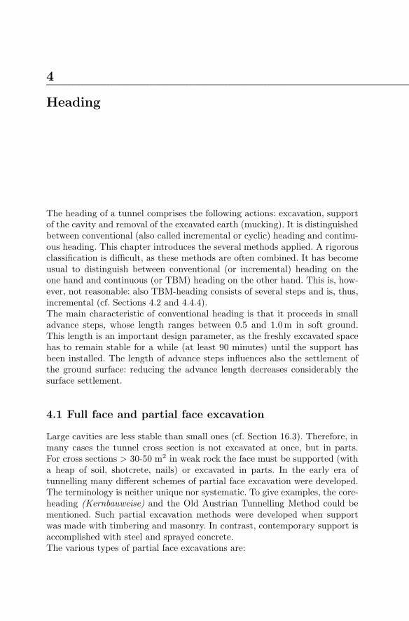
Tail void closure: The outer diameter of the shield is larger than the outerdiameter of the lining in such a way that the moving shield leaves behinda tail void, whose thickness is up to 20 cm. Such a large void can cause thelining rings to shift and/or large surface settlements and must, therefore,be filled (closed) with mortar (’tail gap grouting’ or ’back grouting’). Themortar should set as fast as possible but not too fast (otherwise it cannotbe pumped in). To avoid settlements, the ring tail closure should be doneas soon as possible after excavation and the grouting pressure should beequal to the primary normal stress. Of course, there is no exact way tofulfil this requirement, because the primary stress varies from point topoint and is, at that, hardly known. In addition the grouting pressurefield cannot be precisely controlled. The slot between lining and shieldtail must be plugged, otherwise the grouted mortar can escape. The plug-ging is achieved with steel brushes, whose bristles are filled with grease(Fig. 4.36).A new method of keeping the grouting pressure constant within the tailvoid is to provide a compliant sealing lip which yields only if a thresh-old pressure is reached, so that the void can be filled with a constantpressure.34 It turns out that tail gap grouting cannot completely reversesettlement, even if the volume of the grout considerably exceeds the vol-
34S. Babendererde, Grouting the shield tail gap, Tunnels & Tunnelling Interna-tional, Nov. 1999, 48-49
4.4 Shield heading 101
Fig. 4.36. Sealing of the tail gap
ume of the gap. This can be explained if one considers the mechanicalbehaviour of ground at loading-unloading cycles.35
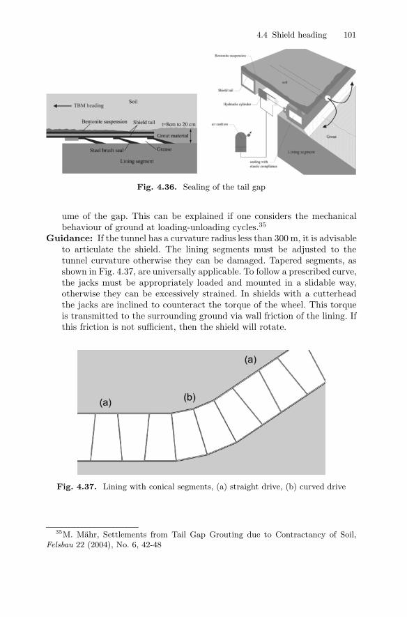
Guidance: If the tunnel has a curvature radius less than 300 m, it is advisableto articulate the shield. The lining segments must be adjusted to thetunnel curvature otherwise they can be damaged. Tapered segments, asshown in Fig. 4.37, are universally applicable. To follow a prescribed curve,the jacks must be appropriately loaded and mounted in a slidable way,otherwise they can be excessively strained. In shields with a cutterheadthe jacks are inclined to counteract the torque of the wheel. This torqueis transmitted to the surrounding ground via wall friction of the lining. Ifthis friction is not sufficient, then the shield will rotate.
Fig. 4.37. Lining with conical segments, (a) straight drive, (b) curved drive
35M. Mahr, Settlements from Tail Gap Grouting due to Contractancy of Soil,Felsbau 22 (2004), No. 6, 42-48

102 4 Heading
Double shield: This shield consists of two parts (Fig. 4.28, 4.29). At thefront shield the cutterhead is installed, at the rear shield (’gripper shield’)the grippers for lateral bracing and the device for placement of the seg-ments are installed. Front and rear parts are connected via a telescopic sec-tion. Thus, the excavation can continue while lining segments are placed.The double shield is a combination of TBM and shield and is intended tooperate in varying rock.In good rock, the cutterhead is buttressed against the rear part, which isconnected to the adjacent rock via the grippers. Thus, the lining segmentscan be installed while the cutterhead works. In weak rock, the two partsof the shield are jointed, and the shield operates as a conventional one.I.e. the excavation has to stop while the line segments are installed.
Tunnel heading machines: Many shields are equipped with a cutterhead,which is the main feature of a TBM (Fig. 4.38).
Fig. 4.38. Shield with TBM (Herrenknecht), 1: cutterhead, 2: conveyor belt, 3:jacks, 4: erector for lining segments, 5: lining
This is why the notions ’shield’ and ’TBM’ are often confound, i.e. takenas synonyms. This is, however, wrong: shields are used in loose groundwhereas (unshielded or ’open’) TBMs are used in hard rock. A combi-nation of both methods is applied in rocks with varying properties. Asa generic term for shield and TBM the word ’tunnel heading machine’(Tunnelvortriebsmaschine) has been launched. A generally accepted clas-sification is

4.4 Shield heading 103
TBM
⎧⎪⎪⎨⎪⎪⎩
open (for rock tunnels)
shielded (for weak or jointed rock/soil){ open face
closed face{ slurry
EPB
A TBM needs to be protected with a shield if the rock is caving in.36
4.4.1 Shield heading in groundwater
If a shield operates below groundwater level, a sufficient safety against upliftmust be assured for all situations to be encountered. In addition, the shieldmust be protected against inrush of water and soil. This can be achieved bysupporting the face with a pressurised fluid (or air). The underlying mecha-nism is explained in Appendix B. The following variants exist:
Shield heading under compressed air: Compressed air provides supportagainst soil and water. Either the front part of the shield or the entiretunnel can be pressurised. In the later case the large volume of compressedair improves safety against air losses, but all works are more difficult sincethey must be done under compressed air. Blow-outs can endanger theworkers and create large craters in the ground surface. By means of abulkhead the compressed air can be isolated in the front part of the shield.The muck has to pass an air lock.The support of the soil is due to a seepage force, which presupposes a highpressure gradient. This can be achieved by coating the soil surface withsealing materials such as bentonite or shotcrete. The pressure is then re-duced within these thin coats, thereby creating high gradients. The effectis the same as if the soil surface were covered with an impermeable mem-brane. Note that the coating can leak if it gets fissures due to shrinkage.Compressed air heading is applicable up to water depths of 30 m, becausethe pressure in the working space is limited to 3 bar for health reasons.A relatively impermeable cover of sufficient height is required to avoidblow-outs. The air supply Q, needed to replace the losses, for soils witha permeability between 10−5 and 10−3 m/s can be estimated with theempirical formula Q (m3/s) ≈ 4 - 8A (m2), where A is the tunnel crosssection.
36Recommendations for selecting and evaluating tunnel boring machines.Deutscher Ausschuß fur unterirdisches Bauen, Osterreichische Gesellschaft fur Ge-omechanik, SIA-Fachgruppe fur Untertagebauten, Tunnel 5/1997, 20-35. See also:Taschenbuch fur den Tunnelbau 2001, Gluckauf Verlag.

104 4 Heading
Slurry-shield: Some of the disadvantages of the support by compressed airare avoided if the support of the face is accomplished by a pressurizedslurry, which in most cases is a bentonite suspension. There is no dan-ger of blow-outs, and all works can be done under normal atmosphericpressure. The support of the ground is achieved by a seepage force whichpresupposes the formation of a mud cake (made of bentonite) on the soilsurface.
Fig. 4.39. Slurry shield37
The soil is excavated with a cutterhead. If the ground is very soft, ex-cavation can even be accomplished with a water jet. The muck is mixedwith the slurry at a ratio of 1:10 and pumped away to a separation plant(Fig. 4.40). Therefore, stones and blocks must be crashed first. The costsfor separation rise at increased content of silt and clay.The slurry pressure needed to support the ground must be estimated orcalculated (see Chapter 17). To maintain the prescribed pressure and toreplace any losses due to mucking, a reliable control of the pressure mustbe guaranteed. An air cushion is provided in a part of the pressurised space(Fig. 4.39). Due to the high compressibility of air, the pressure of this aircushion is much less susceptible to small volume changes. By tuning theair pressure and balancing the removed and added slurry, the pressure canbe controlled with an accuracy between 0.05 and 0.1 bar.For maintenance reasons and in order to remove blocks, the excavationchamber can be entered via an air lock. During maintenance, the slurry isreplaced by compressed air. Note, however, that pressurized air is a riskymethod of support, since it can easily escape (blow-outs). For this reasondaylight collapses occurred during the headings of the Grauholz and ofthe Westershelde tunnels. An alternative is to freeze the soil ahead of the
37Tunnels & Tunnelling International, March 2004, p. 15

4.4 Shield heading 105
Fig. 4.40. Left: Separation plant, right: working principle of a hydrocyclon
face and carry out the maintenance works under the protection of frozensoil.One of the largest slurry shield machines is the ’Trude’ of Herrenknecht,which was utilised for the fourth tube of the Elbe tunnel (3.1 km long)and later in Moscow. The cutterhead is 400 t heavy, has a diameter of14.2 m and operates with 2.5 rotations per minute. It can excavate softsediments, gravel and rock.With the ’Thixshield’ technique (Fig. 4.43) the face is excavated with amovable roadheader which also sucks and extracts the muck. The road-header has some advantages compared with a full face cutterhead:• smaller torque• not limited to circular cross sections• obstacles can be easier removed
Earth-pressure-balance (EPB) shield: Instead of a slurry, the face issupported with a mud, formed of the excavated soil. The soil enters theexcavation chamber through openings in the cutterhead. In most cases,water and some other additives (e.g. polymer foames) are added to ren-der the excavated soil supple. Otherwise heat will be developed due tofriction with the rotating cutterhead. The thick consistence of the mud(compared with a slurry) calls for a higher cutterhead torque (ca 2.5 timeshigher than for slurry shields). On the other hand, the torque is limited by
38Tunnels & Tunnelling International, October 2001, p. 2639Herrenknecht40Philipp Holzmann
106 4 Heading
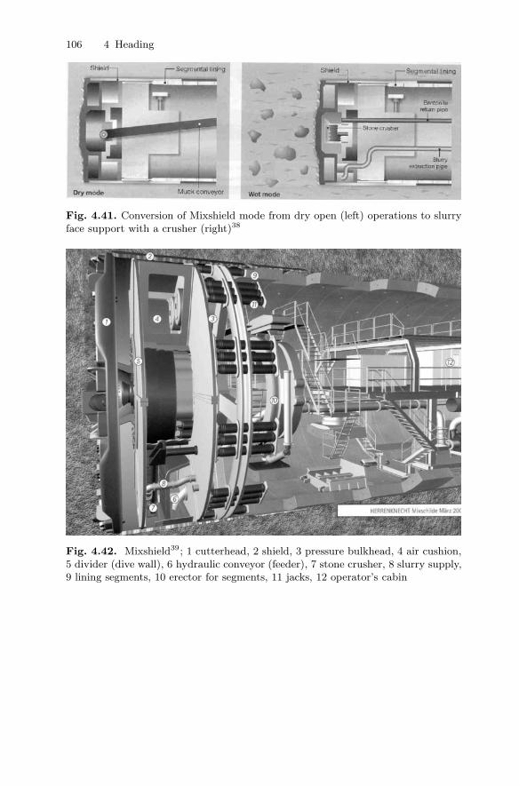
Fig. 4.41. Conversion of Mixshield mode from dry open (left) operations to slurryface support with a crusher (right)38
Fig. 4.42. Mixshield39; 1 cutterhead, 2 shield, 3 pressure bulkhead, 4 air cushion,5 divider (dive wall), 6 hydraulic conveyor (feeder), 7 stone crusher, 8 slurry supply,9 lining segments, 10 erector for segments, 11 jacks, 12 operator’s cabin

4.4 Shield heading 107
Fig. 4.43. Thixshield: excavation chamber with cutter and bulkhead40
the available friction between lining and rock. Thus, the diameters of EPBshields are limited to ca 12 m. The control of the mud pressure, neededto support the face, is achieved by tuning the following quantities:• rotation speed of the cutterhead (approx. 2-3 revolutions per minute)• rotation speed of the screw conveyor which removes the muck from the
front chamber (approx. 4-5 revolutions per minute). The mud shouldbe sufficiently thick to plug the conveyor screw otherwise the pressurein the pressure chamber will drop
• advancing the shield by the jacks.Due to the compressibility of the mud and the inhomogeneous non-hydrostatic pressure distribution, the pressure control is not precise, itfluctuates by ±0.5 bar.The mud contains 50 to 70% solids and can thus be mucked with trucks orconveyor belts. In general, its dumping capability can be easily assured,if the bentonite content is not too high.
The shield cannot start working until the pressure chamber is filled. This ismuch simpler with slurry shields than with EPB shields.The appropriate conditioning of the muck with foam etc. makes the applica-tion of EPB shields possible in a large variety of grounds (including gravel).Attention should be paid to heterogeneous grounds, where the various soillayers need different support pressures.The drive of a EPB-TBM in the underground of Porto (Portugal) proved tobe particularly difficult. The encountered granite was in some places weath-ered and exhibited the behaviour of soft soil. So when the TBM encounteredpartly weathered and partly unweathered granite, the mud pressure could notbe controlled. As a result, several collapses occured. The remedy was to letpressurized slurry act upon the mud. In this way, the stabilizing pressure onthe face was much better controllable.
41Wirth Howden Tunnelling42Herrenknecht

108 4 Heading
Fig. 4.44. EPB-shield41
Fig. 4.45. EPB-shield42; 1 face, 2 cutterhead, 3 pressure chamber, 4 bulkhead, 5jacks, 6 conveying screw, 7 segment erector, 8 lining with segments

4.4 Shield heading 109
4.4.2 Tunnelling with box- or pipe-jacking
The tunnel heading proceeds with jacking of precast support elements (pipesor boxes/frames) while the ground is excavated or pushed away at the face(Fig. 4.46, 4.47). Box-jacking is usually applied to build subways under exist-ing roads or rail tracks without interrupting the traffic.
Fig. 4.46. Pipe-jacking
Fig. 4.47. Pipe-jacking with hydraulic mucking43
43Herrenknecht Microtunneling

110 4 Heading
Fig. 4.48. Horizontal directional drilling with reaming44
The only difference between pipejacking and shield heading is the positionof the jacks: for pipejacking they are situated in the start shaft and/or atintermediate jack stations, whereas for shield heading they are placed directlybehind the shield.The excavated diameter is slightly larger than the pipe diameter, so that theresulting gap can be grouted with bentonite to reduce friction.
4.4.3 Microtunnels
Microtunnels are used for the trenchless laying of cables and other lifelines.Since it is not allowed to work in spaces with ∅ < 0.8m, the heading isaccomplished uncrewed by means of jacks and hammers that are installed atthe excavation face. The soil is either displaced laterally, removed by screwconveyors or flushed. An important issue is the control of heading direction.A possible method is to use an asymmetric hammer which is permanently
44Herrenknecht HDD Rigs, February 2003

4.4 Shield heading 111
rotated to drive straight on, whereas the rotation is stopped whenever a curveis to be traced.
4.4.4 Speed of advance
The tunnel heading is composed of various steps, some of which are consecu-tive. Therefore it is important to adjust the individual steps relatively to eachother.Let the rate of excavation be va and let ta be the daily operation time of aTBM. The rate of support is vs and the time (per day) needed for support ists. Let the rates va and vs be prescribed by the available machines and theground. The question is now, how to determine ta und ts in such a way that amaximum advance rate is achieved? This means that the daily advance lengthz or the advance rate V = z/24 h has to be maximized. We first determine zin dependence of ts and take into account that ta + ts = 24 h− tw. Herein, twis the daily downtime for maintenance. Thus we have ta = 24 h− tw − ts, andthe daily advance length is z = Min{vata; vsts} or
z = Min{va(24 h − tw − ts); vsts} (4.1)
The relation 4.1 is shown in Fig. 4.49 (left). Obviously, for
ts = ts0 := (24 h − tw)va
vs + va
the daily advance length z becomes a maximum zmax:
zmax =vavs
va + vs(24 h − tw) . (4.2)
Thus, the maximum advance rate Vmax results to:
Vmax =zmax
24 h=
vavs
va + vs· 24 h − tw
24 h. (4.3)
From the plot of equation 4.3 in Fig. 4.49 it can be seen that the increase rateof Vmax decreases with va.In reality, the advance rate depends on many factors and cannot be given’across the board’. Some reference points are:
top heading 5 m per dayheading with side galleries 3 m per dayTBM in rock45 8 m per dayshield heading in soil 20m per day
45A record advance rate of 48 m/day has been achieved with a TBM at theLotschberg tunnel construction site.

112 4 Heading
Fig. 4.49. Daily advance length z vs. the support time ts; speed of advance v vs.excavation rate va
4.4.5 Drive-in and drive-out operations
Often, the shield moves between two shafts, the start (or launch) and thetarget shaft (Fig. 4.51). The back wall of the start shaft serves as abutmentfor the jacks. A lining length of at least 30 to 40 m is required to take onthe jack thrust and transmit it to the surrounding ground by means of wallfriction.To drive the shield into the ground, starting from a shaft, a retaining wall hasto be penetrated first.46 This can be difficult if the retained soil has a verylow strength or if the tunnel is driven below the groundwater level. Usuallythe wall is removed in strips of 0.5 to 1 m width and the face is temporarilysupported with a soil heap. As a support measure, the adjacent soil can begrouted or frozen. If the heading has to proceed below groundwater level,the launch shaft can be put under compressed air. Alternatively, a membrane(Fig. 4.50) creates an intermediate partition between the ground and theshaft (caisson). The shield is then lowered in front of the membrane wall. Thepressure difference is successively adjusted until the shield can be driven intothe soil.A drive-out operation is illustrated in Fig. 4.51.
4.4.6 Problems with shield heading
The fact that a shield protects against cave-ins of the tunnel wall does notmean that shield heading is free of difficulties. It should be noted that the costsof a shield or a TBM are low compared with the heading costs. Nevertheless,a jam can delay the heading progress for a long time and can, thus, causeimmense consequential costs.One should also consider the following items:
46The corresponding opening at the wall is called ’eye’.47Herrenknecht Mixshields September 200248Tunnelling Switzerland, Swiss Tunnelling Society, Bertelsmann 2001

4.4 Shield heading 113
Fig. 4.50. Membrane between soil and caisson wall47
Fig. 4.51. TBM breakthrough48
Drillability: The advance speed in rock is limited by the fact that the ro-tational speed of the cutterhead cannot be increased beyond some limit.The bearings and the seals of the disc cutters allow a maximum veloc-ity of 150 m/min. This imposes a limit to the rotational velocity of thewheel. An increasing number of disc cutters on the wheel increases alsothe downtime for maintenance. Thus, an efficient translation velocity is≥ 3 to 4 mm/rotation. If a disc cutter is loaded more than allowed itvibrates and can be damaged. Its repair or replacement is difficult.
Stability of the face: Problems can appear when it encounters weak zonesfilled with soft soil. The cutterhead can jam due to accumulated or blockymuck. If the shield retracts to remove the problems at the face, then moresoil or blocks can collapse into the resulting cavity. Advance grouting istedious and can immobilize the cutterhead. Often, conventional headingis used until more favourable rock is encountered.

114 4 Heading
Penetrating squeezing rock: It is recommended that in squeezing rock(Sect. 14.10) the overbreak is increased from the usual 6-8 cm to 14-20 cmby means of a sufficiently large cutterhead. In addition, more powerfulljacks should be used that are capable of pushing the shield even if it issqueezed with a pressure of 2-5 MPa. Of course, the lining segments mustbe appropriately designed, and any standstill should be avoided.
4.5 Comparison of TBM with conventional heading
The choice between TBM and conventional excavation is an often faceddilemma. All over the world, TBM’s are increasingly applied whereas con-ventional excavation techniques are rather used in difficult or varying ground,in short tunnels and in tunnels of varying cross sections.Recently, the range of TBM applicability has been enlarged. Improved drillingtechniques can now penetrate hard rock (qu >400 MPa). Also jointed and softrock can be penetrated with retracted cutterhead, appropriate shields andNATM support.By means of its construction, a shield guards against the cave-in of the tun-nel roof and, possibly, also of the face, whereas drill & blast can be veryproblematic whenever unforeseen weak zones are encountered.The Los Rosales Tunnel in Bogota was, for example, excavated in a hardsandstone which, however, was locally so weak that it rushed into the tunnelthrough the grouting drillholes (in amounts up to 6m3). The tunnel couldonly be completed with a TBM.Referring to work safety: The advantage of a better support by the TBMcan be partially overridden by the crowded working space. The uniform workin TBM heading is easier to learn than in drill & blast heading. Anotherargument in favour of the TBM technique is the avoidance of overbreak, which,on average, amounts to 10% for drill & blast and increases to 25% of the tunnelcross section for jointed rock or improper blasting (see also Section 4.7).Comparing costs one should take into account that TBM heading is connectedwith high installation costs, so that it is profitable only for considerable tunnellengths (Fig. 4.52).
Advantages of conventional heading with shotcrete support
• Heading of varying cross section (not only circular ones)• Equipment can also be used for other purposes and can be easily replaced• Low installation costs• Adaption to geologic conditions is easy.
Disadvantages of conventional heading with shotcrete support
• Personnel are relatively unsecured close to the excavation face

4.6 Rock excavation 115
Fig. 4.52. Comparison of costs TBM – drill & blast
• Advance rate is limited to approx. 5-7 m/day• Heading in difficult ground conditions (especially below groundwater level)
is only possible if combined with expensive precautions• In most cases an inner lining has to be added.
Advantages of shield heading with segmental lining
• Soft soil, also below groundwater level, can be excavated• Sufficient safety, as the face is supported immediately• Prescribed cross section is precisely excavated• High advance rates, in particular after a learning phase of ca 1-2 months• High quality lining due to pre-fabrication, a supplementary lining is not
needed• Low costs if the tunnel is sufficiently long.
Disadvantages of shield heading with segmental lining
• Limited to circular cross sections of constant diameter• High installation costs• Long learning phase of the crew• Expensive drive-in operations• Adjustment to varying ground conditions is difficult• Machine damages cause total downtimes.
4.6 Rock excavation
The words ’drilling’, ’boring’ and ’cutting’ are more or less synonymous indenoting rock excavation.

116 4 Heading
4.6.1 Drilling of boreholes
In tunneling, boreholes are drilled on the following purposes:
• exploration (site investigation)• drill & blast• grouting• installation of bolts, spiles and other types of reinforcement.
Drilling comprises breakout, removal of the rock and cooling of the core bit.49
Removal of the drill dust and chips as well as cooling is accomplished by flush-ing (Fig. 4.53). Exploration drillings are flushed with water, whereas percus-sion drillings are flushed with compressed air. Viscous fluids are used if thewall of the borehole has to be supported.Drilling of blastholes requires high speed, low wear of the core bit and highprecision (an accuracy of 0.1◦ is required for accurate blasts), whereas explo-ration drillings aim at a good core recovery and stable borehole walls. Drillingsfor oil and gas production aim at minimizing disturbance of the surroundingrock.
Fig. 4.53. Drilling with flushing50
Drilling is performed with percussive and rotary motion of the core bit. In theearly days of mining, chisel and sledge hammer were used achieving rates of1 m/h, whereas nowadays hydraulic percussive drilling with tungsten-carbidcore bits can achieve rates up to 300 m/h (Fig. 4.54). Loose soils are drilledwith augers; so-called continuous flight augers are increasingly used.Percussive drilling is either driven pneumatically or hydraulically. Hydraulicdrive is advantageous for several reasons: the boreholes are more precise, andthey are driven twice as fast with only 1/3 of the pneumatically requiredpower. Hydraulic compressors (electrically or diesel powered) are not as heavyand bulky as pneumatic ones. Moreover, the absence of compressed air dis-charges guarrantees visibility.
49See also: J.A. Franklin and M.B. Dusseault: Rock Engineering, McGraw Hill,1989
50AtlasCopco Rock Tools51AtlasCopco, Underground Rock Excavation

4.6 Rock excavation 117
Fig. 4.54. Rock drilling technology51
The percussion is obtained by the impact of a piston. The impact momentumpropagates along the drilling rod and eventually hits the rock. For long rodsthe energy is substantially reduced by wall friction. For this reason the hitshave to be applied near the tip of the drill rod by means of a downholehammer, if the drilling rod is longer than ca 120 m. For directional drillingdownhole turbines are used.To maximize the drilling speed, the following parameters have to be adjusted:thrust, rotation speed, rheological properties of the flushing fluid and thehydraulic drive. For soft rock a higher rotation speed (60-100 revolutions perminute) is advised than for hard rock (40-70 revolutions per minute). Withincreasing rotation speed the thrust should be reduced. For weak rock (qu <200 MPa) the core bit should be equipped with teeth and for hard rock withbuttons. Disc cutters cause chipping of the rock (see Section 4.6.2). Tungstencarbide and artificial diamonds increase the lifetime of drilling tools.To choose the appropriate drilling tool, the following parameters have to betaken into account: rock properties, permeability, presence of dispersive orswelling clay minerals, rock temperature and stress state and rheological prop-erties of the flushing fluid. The proper choice is more difficult for stratifiedrock with changing properties.A difficulty arises if the excavated rock disintegrates to mud. Dispersivity(mainly due to clay minerals) means that water disintegrates the rock. Thesusceptibility of a rock to dispersivity is measured with the slake durability

118 4 Heading
test: 10 pieces of rock, weighing 40 to 60 g each, are oven-dried and then putinto a sieve drum that slowly rotates in water for 10 minutes. The ratio of theremaining to the initial dry weights of the pieces within the drum is termedId2.Clay minerals, especially swelling ones, may cause difficulties by renderingthe muck sticky. Countermeasures are properly designed excavation tools (ap-propriate geometry avoiding narrow spaces), appropriate surface coatings andflushing.Waterjet drilling is applied for special purposes, e.g. for rockbolt boreholes(because of the rough borehole walls).52 The waterjet can be steady or pul-sating, the water pressure should be approx. 100 times larger than the un-confined strength of the rock. The rock is removed due to the impact of thewater, which can flow continuously or in form of droplets. The excavationprocess can be enhanced by particles suspended within the water. An alter-native mechanism is cavitation erosion (impacting micro-jets from implodinggas bubbles).53
4.6.2 Rock excavation with disc cutters
The advance rate of a TBM is a very important item for planning and biddingtunnel projects. It should therefore be predicted as precisely as possible. So-called TBM performance prediction models have been developed, among themthe ones of NTH (Norwegian Institute of Technology) and CSM (ColoradoSchool of Mines).The excavation of rock is a very complex process that depends on factors,which are hardly controllable. Thus, most of the TBM prediction models arebased on empirical correlations of the several controlling parameters. Thelack of rational analysis of the underlying processes limits their applicabilityto already existing methods and machines, i.e. extrapolations to new technicaldevelopments are questionable.The statements in this section, being based on mechanical concepts ratherthan regression analysis of row data, are intended to give a rough orientationand are not meant as a tool for precise predictions.Disc cutters (also called ’discs’, Fig. 4.55) exert a high pressure and thusfragment the rock, see Fig. 4.56. The discs exert forces up to F = 250 kN thatfragment the rock into flat chips (fragments). Their bearings (Fig. 4.55) aredesigned in such a way that friction is reduced when high thrust is exertedagainst the rock. Cutters with V -shaped cross sections are no more used,because wear progressively changes the contact area with the rock. They havebeen replaced with ’constant cross section’ discs (Fig. 4.56).
52Waterjets are also applied in coal mining to avoid sparks.53A.W. Momber, Wear of rocks by water flow, Int. J. of Rock Mechanics and Min-
ing Sciences, 41 (2004), 51-6854AtlasCopco, Underground Rock Excavation

4.6 Rock excavation 119
Fig. 4.55. Left: cutter, right: cutter bearing (Herrenknecht)
Fig. 4.56. Working principle of cutters54
As shown in Fig. 4.57, a cutter has a distance (radius) R from the TBM-axis.The TBM cutterhead rotates with N revolutions per time unit. The cutterhas the radius r (typical cutter diameters vary between 38 and 48 cm) androtates with n revolutions per time unit. Neglecting slip we have
n =2πR2πr
N =R
rN .
Thus, the linear velocity of the cutter amounts to v = 2πNR. To controlvibrations, v is limited to approx. 150 m/min. Another reason to limit therotation speed (i.e. N) is to avoid overly large centrifugal forces of the rockchips. Therefore, for given Rmax values, N is also limited. The forces act-ing upon a cutter and the instantaneous velocity distribution are shown inFig. 4.58.Clearly, the total torque of the cutterhead amounts to

120 4 Heading
Fig. 4.57. Position of a cutter in a TBM
Fig. 4.58. Forces (T and F ) and velocity distributions in the cutter. Left: sliding,right: rolling.
Mt = Σi(TiRi) (4.4)
where summation is run over all cutters. Note that also in case of rolling(Fig. 4.58, right) there is an abrasion of the wheel due to the relative slipbetween cutter and rock (Fig. 4.59).
55J.B. Cheatham,(1958). An analytical study of rock penetration by a single bittooth. Proc. 8th Annual Drilling and Blasting Symp., Univ. of Minnesota, Min-neapolis; Pariseau and Fairhurst (1967). The force penetration characteristic forwedge penetration into rock. Int. J. Rock Mech. Min. Sci. & Geomech. Abstr. 4:165-180.

4.6 Rock excavation 121
Fig. 4.59. P is the instantaneous pole of rotation. The instantaneous velocity v isnormal to AP and has, therefore, a slip component vslip that causes abrasion.
Fig. 4.60. Chipping of rock viewed as punching problem of plasticity55
The rock is chipped between two adjacent cutters, as shown in Fig. 4.60. Asmall part or rock directly adjacent to the cutter is not chipped but crushedinto powder. In the elastic regime the relation between punching force F andindentation s is linear according to the equation of Hertz:
s =F
bEκ
with
κ =1π
[λ(1 − μ2
steel) + 1 − μ2rock
],
λ = Erock/Esteel ,
E = Erock .

122 4 Heading
We assume that this relation holds for F < Fl. At the limit force Fl, plas-tic punching according to Prandtl’s theory is assumed to set on. Clearly,the application of this theory is limited to isotropic non-brittle materials. Itis, however, common practice in rock mechanics to use plasticity theory andcharacterize the strength of rock by ϕ and c values. To this extent, the ap-plication of plasticity theory appears to be reasonable, at least for a rough,though rational, assessment of the considered fragmentation process.For vanishing internal friction of the rock, i.e. ϕrock = 0, the punching loadFl can be estimated as follows. With the length a (Fig. 4.61) estimated as
a = 2√r2 − (r − s)2 ≈ 2
√2rs (4.5)
we obtain from Prandtl’s solution:
F
ab≈ 5c,
where c is the cohesion of the rock (for ϕ = 0 we have c = qu/2, where qu isthe unconfined (uniaxial) compression strength).
� F ≈ 5abc≈ 10
√2rs bc
With (4.5) we obtain the punching force, i.e. the required thrust per cutter,as
F ≈ 200κrbc2/E= 50κrbq2u/E= 100 κ r b ε
Fig. 4.61. To the estimation of the punching length a
with ε being the fragmentation work per unit volume (Fig. 4.62): ε = 12quεl.
ε can be obtained from a uniaxial compression test. Regarding the specific

4.6 Rock excavation 123
fragmentation work, i.e. the fragmentation work per unit volume, it is oftenargued that it must increase with increasing surface of debris. This is a rea-sonable but yet unproven assumption. Assuming the specific fragmentationwork ε as a given quantity and neglecting the work for linear penetration indirection of the tunnel axis, we obtain the penetration work per revolution as
W = 2πMt/(Ad)
with the applied torque Mt, the tunnel cross section A and the penetrationdepth d according to Fig. 4.60. With A = πD2/4 andMt according to Equ. 4.4we obtain Mt ∝ D3 . The net penetration rate is N · d.
Fig. 4.62. Fragmentation work per unit volume ε =Rσ dε = 1
2qu εl
It should be taken into account that the position of a cutter is fixed on thecutterhead. Thus, s cannot be always adjusted to the limit punching force.Whenever the cutter touches muck (from previous punching), which has lowerE and c values, the prevailing force F drops considerably. The bearing isdesigned in such a way that the rolling friction increases with decreasingthrust. As a result, abrasion dramatically increases. This leads to a reductionof indentation (since the position of the bearing is fixed) and, thus, to a furtherreduction of force. The cutter keeps sliding and abrasion proceeds very fast.It has been observed that a good muck removal reduces abrasion.It should be added that hard rock boring is not yet completely understood.The equations derived above are merely an attempt to analyse the under-lying processes and to give some qualitative insight into the interrelationsbetween the involved quantities. A quantitative check against experiments isquestionable.56 Regarding e.g. the punching force as derived from the theoryof plasticity, one should pay attention to the fact that the friction angle ϕ maysensitively affect the results. However, the experimental determination of ϕ
56R. E. Gertsch, Rock Toughness and Disc Cutting. PhD thesis, University ofMissouri-Rolla, 2000.

124 4 Heading
is difficult. Moreover, ϕ is stress-dependent and thus not a material property.The prediction of TBM performance (i.e. penetration rate and abrasion de-pending on thrust, torque, rotation speed and TBM design) is therefore stillempirical.57
An alternative application of disc cutters is undercutting (Fig. 4.63 and 4.64),where the disc cutter pares the rock from a pre-bored space.
Fig. 4.63. Undercutting at the Uetliberg tunnel58
4.6.3 Abrasion
Abrasion of the excavation tools is an important issue. Several methods havebeen proposed to rate the abrasivity of rock. Among them are:
CERCHAR (Laboratoire du Centre d’ Etudes et Recherches des Charbon-nages): The tip of a steel conus is loaded with 7 kg and scratched 6 timesover a length of 1 cm along a fresh fracture surface of the investigatedrock. The flattening of the tip due to the abrasion is then measured.CERCHAR indices, varying from 1 to 6, are then assigned to diametersof the truncated tip (varying from 0.1 to 0.6 mm).
57see e.g. University of Trondheim (NTH), 1994, ”Hard Rock Tunnel Boring”,Project report 1 - 94.
58S.Mauerhofer, M. Glattli, J. Bolliger, O. Schnelli: Uetliberg Tunnel: Stagereached by Work and Findings with the Enlargement Tunnel Boring Machine TBE,Tunnel 4/2004.
59L. Baumann, U. Zischinsky, Neue Lose- und Ausbautechniken zur maschinellen“Fertigung” von Tunneln in druckhaftem Fels. In: Innovationen im unterirdischenBauen, STUVA Tagung 1993 (ISBN 3-87094-634-2), 64-69.

4.6 Rock excavation 125
Fig. 4.64. Principles of rock cutting. Left: usual technique, right: undercutting59
LCPC (Laboratoire Central des Ponts et Chaussees): First the rock is brokendown (a sample of 500 g with grains sizing from 4 to 6.3 mm is whirledwith a standardised steel propeller at 4,500 revolutions per minute). Theindex ABR is defined as the weight loss of the propeller (due to abrasion)per 1 t of rock.
Schimazek’s coefficient of abrasivity F = V dσz/100 withV : volumetric percentage of quartzd: mean size (in mm) of quartz grainsσz : tensile strength (MN/m2) of the rock.Examples of rating:F < 0.05: not very abrasiveF > 2: extremely abrasive
4.6.4 Drilling: history review
In ancient times rock was bored with hammer and chisel. From the 16th tothe 19th century ’stoking’ was applied: The tunnel face was heated by fire andsubsequently cooled with water. As a consequence, cracks appeared that madethe rock easier to excavate. Rock blocks were removed by splitting: Woodenspikes were placed into drilled holes, added water caused swelling of the spikesand split the rock. The drill & split method is also applied nowadays, wherethe rock is split with the aid of steel splines. This method is applied where

126 4 Heading
Fig. 4.65. Disc cutters from Lotschberg base tunnel. Left: Worn disc cutters
vibrations due to drill & blast have to be avoided. The maximum excavationrate with this technique is 1 m per 24 h.
4.7 Profiling
For practical reasons the excavated profile does not coincide with the intendedone. Underprofile (i.e. defficient excavation) can be detected by means of tem-plates or geodetic devices. Subsequently the remaining rock has to be removed(’scaling’), e.g. with excavators or cautious blasting.Overprofile (also called overbreak), i.e. surplus excavation, can be due to badgeological conditions, and is thus inevitable, and/or due to improper excava-tion. It causes additional costs for the contractor, as it has to be filled withshotcrete. Thus, the distinction between both types of overbreak is of eco-nomic importance. A certain amount of overbreak, represented by a strip ofthe width d (Fig. 4.66), should be allowed for, as required by the technicalequipment. d should be specified by the contractor. A strip of the width D(Table 4.2) is to specify the ’geological’ overbreak, i.e. the overbreak imposedby the geological conditions and is to be payed to the contractor.60
If not otherwise specified, SIA 198 recommends the following expressions forD, with A being the theoretical tunnel cross section:
60Swiss Code SIA 198

4.8 Mucking 127
����������������������������
����������������������������
hatched area: geologic overprofile to be remunerated by the contractor
d (overprofile taken into accountby the contractor)
theoretical boundary of excavation
real boundary of excavation
D (according to Tab. 4.2)
Fig. 4.66. Refundable overbreak (according to SIA 198) for tunnels excavated con-ventionally or with roadheader
excavation method D
drill & blast Max{0.07√A, 0.40 m}roadheader Max{0.05√A, 0.40 m}soil, without shield Max{0.05√A, 0.40 m}shield Max{0.03√A, 0.25 m}TBM Max{0.03√A, 0.20 m}
Table 4.2. Strip width D referring to Fig. 4.66 (SIA 198)
4.8 Mucking
The removal of the excavated rock/soil is known as mucking and consistsof loading up, transport and unloading of the muck (also called ’spoil’). Fortransport (haulage) the following variants are available:
Trackless transport: Usual earthwork trucks are used. Of course, provisionshould be taken for the reduced production of harmful combustion prod-ucts (cf. Section 2.3.1). A good carriageway is important to enable a speedof ca 50 km/h. The inclination is limited to approx. 7%, the necessarywidth of the tunnel is 7 to 8 m. The requirements for fresh air supply arevery high: A dumper of 300 PS (220 kW) needs 2,000m3 fresh air perminute.
Railbound mucking (track transport) is also applicable in crowded spa-ces, i.e. for spans <6 m. Usual track gauges are between 600 and 1435 mm,the maximum inclination is 3 %, the minimum curvature radius is ca 7 m,the velocity is limited to ca 20 km/h. The locomotive is powered by diesel
61http://www.schoema-locos.de

128 4 Heading
Fig. 4.67. Railbound mucking61
or electric motors. In the latter case, the power is delivered by accumula-tors. The power consumption is lower than with trucks.
Continuous conveyors: Conveyors have a very large transport capacity (upto 200 t/h).62 A separate transport for personnel is needed as well as astone crusher and a dosing device. Apart from the high transport capacity,their main advantage is safe, clean and silent transport. But intensivemaintenance is needed, because their outfall implies downtime of all otherworks. A minimum curvature radius of 500 m is required. Conveyors canbe mounted on rail waggons.
Fig. 4.68. Mucking with continuous conveyor63
62S. Wallis: Continuous conveyors optimise TBM excavation in the Blue Moun-tains and Midmar, Tunnel 3/95, 10-20
63Rock-Machines Sweden AB

4.8 Mucking 129
Tunnel muck is utilised, if possible, as aggregates for shotcrete and cast con-crete and for fills. The utilisation as aggregates requires an appropriate min-eralogical composition and, possibly, crushing and/or washing to remove thefines. In general, muck from drill & blast in igneous rock is more appropriateas aggregates than muck from TBM’s.If muck cannot be integrated immediately after heading, it has to be stored ina disposal dump. While the unloading of trucks is straightforward, rail tracksneed special unloading facilities (an example is given in Fig. 4.69).
Fig. 4.69. Unloading from bottom outlets