Embed Size (px)
Citation preview
ORIGINAL ARTICLE
Head-mounted mixed reality projection display for gamesproduction and entertainment
Daniel Kade1• Kaan Aksit2
• Hakan Urey2• Oguzhan Ozcan3
Received: 20 November 2014 / Accepted: 3 April 2015 / Published online: 19 May 2015
� Springer-Verlag London 2015
Abstract This research presents a mixed reality (MR)
application that is designed to be usable during a motion
capture shoot and supports actors with their task to per-
form. Through our application, we allow seeing and ex-
ploring a digital environment without occluding an actor’s
field of vision. A prototype was built by combining a
retroreflective screen covering surrounding walls and a
headband consisting of a laser scanning projector with a
smartphone. Built-in sensors of a smartphone provide
navigation capabilities in the digital world. The presented
system was demonstrated in an initially published paper.
Here, we extend these research results with our advances
and discuss the potential use of our prototype in gaming
and entertainment applications. To explore this potential
use case, we built a gaming application using our MR
prototype and tested it with 45 participants. In these tests,
we use head movements as rather unconventional game
controls. According to the performed user tests and their
feedback, our prototype shows a potential to be used for
gaming applications as well. Therefore, our MR prototype
could become of special interest because the prototype is
lightweight, allows for freedom of movement and is a low-
cost, stand-alone mobile system. Moreover, the prototype
also allows for 3D vision by mounting additional hardware.
Keywords Head-mounted projection display � Mixed
reality � Motion capture � Laser projector � Immersive
environments � Games production
1 Introduction
Entertainment industry products such as video games and
films are deeply depending on computer-generated imagery
(CGI). There are many cases where CGI characters’
movements need to meet real-world physics. One of the
widely used ways is to capture motions of human actors in
a dedicated vision-based motion capture [24] studio as
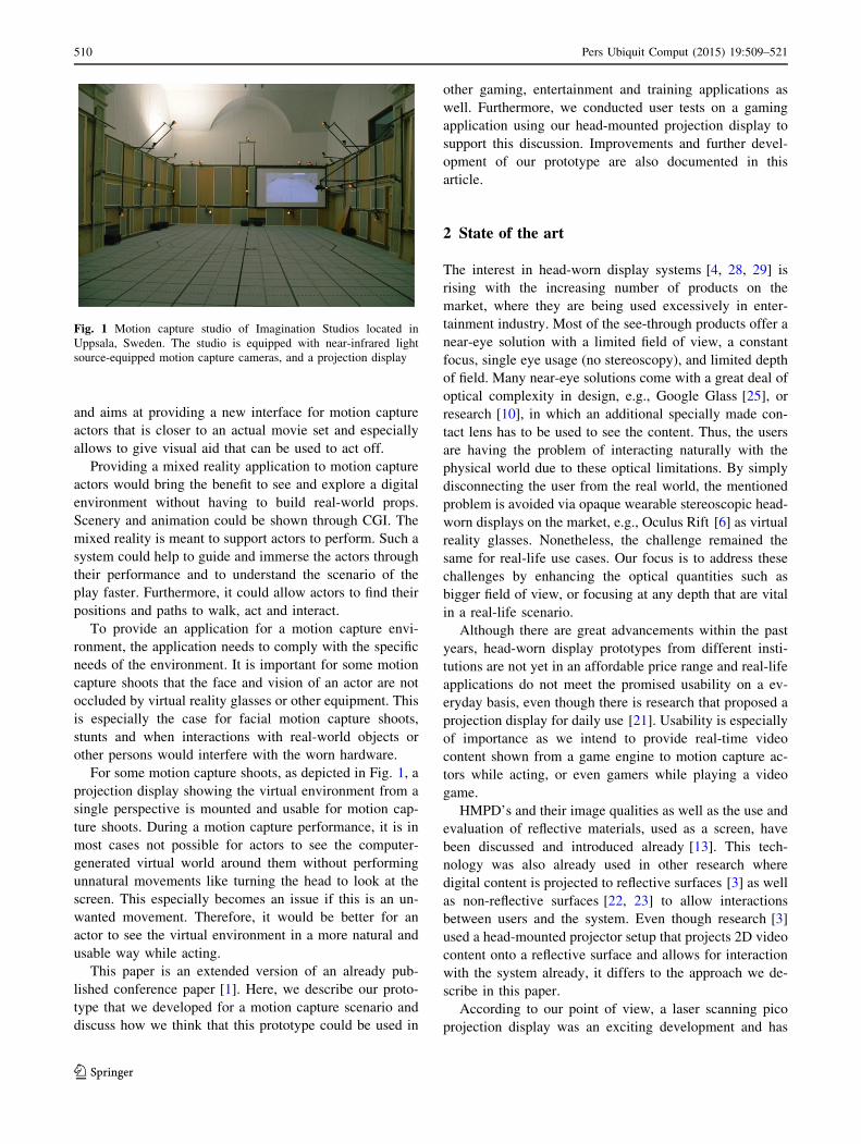
shown in Fig. 1. Alternative motion capture techniques
beside vision-based techniques have also been investigated
for daily activities and professional motion capture [26,
35]. A typical setup of a motion capture studio is as shown
in Fig. 1; a large space shoot area, motion capture cameras
aiming at the shoot area, conventional cameras and
sometimes projection displays, film cameras and pre-vi-
sualization (previs) cameras.
Motion capture actors are generally using a quite
minimal scenery as acting environment. Usually simple
metal or wooden props are used to create the acting envi-
ronment. Previous research has shown that actors can ex-
perience challenges to perform in such an environment and
that these quite diversely skilled ‘‘actors’’ would benefit
from improvements in a motion capture shoot proce-
dure [17, 18]. This is why this research addresses this issue
& Daniel Kade
Kaan Aksit
Hakan Urey
Oguzhan Ozcan
1 Malardalen University, Hogskoleplan 1, 721 23 Vasteras,
Sweden
2 Department of Electrical Engineering, Koc University,
Rumeli Feneri Mh., 34450 Istanbul, Turkey
3 Arcelik Research Centre for Creative Industries, Koc
University, Rumeli Feneri Mh., 34450 Istanbul, Turkey
123
Pers Ubiquit Comput (2015) 19:509–521
DOI 10.1007/s00779-015-0847-y
and aims at providing a new interface for motion capture
actors that is closer to an actual movie set and especially
allows to give visual aid that can be used to act off.
Providing a mixed reality application to motion capture
actors would bring the benefit to see and explore a digital
environment without having to build real-world props.
Scenery and animation could be shown through CGI. The
mixed reality is meant to support actors to perform. Such a
system could help to guide and immerse the actors through
their performance and to understand the scenario of the
play faster. Furthermore, it could allow actors to find their
positions and paths to walk, act and interact.
To provide an application for a motion capture envi-
ronment, the application needs to comply with the specific
needs of the environment. It is important for some motion
capture shoots that the face and vision of an actor are not
occluded by virtual reality glasses or other equipment. This
is especially the case for facial motion capture shoots,
stunts and when interactions with real-world objects or
other persons would interfere with the worn hardware.
For some motion capture shoots, as depicted in Fig. 1, a
projection display showing the virtual environment from a
single perspective is mounted and usable for motion cap-
ture shoots. During a motion capture performance, it is in
most cases not possible for actors to see the computer-
generated virtual world around them without performing
unnatural movements like turning the head to look at the
screen. This especially becomes an issue if this is an un-
wanted movement. Therefore, it would be better for an
actor to see the virtual environment in a more natural and
usable way while acting.
This paper is an extended version of an already pub-
lished conference paper [1]. Here, we describe our proto-
type that we developed for a motion capture scenario and
discuss how we think that this prototype could be used in
other gaming, entertainment and training applications as
well. Furthermore, we conducted user tests on a gaming
application using our head-mounted projection display to
support this discussion. Improvements and further devel-
opment of our prototype are also documented in this
article.
2 State of the art
The interest in head-worn display systems [4, 28, 29] is
rising with the increasing number of products on the
market, where they are being used excessively in enter-
tainment industry. Most of the see-through products offer a
near-eye solution with a limited field of view, a constant
focus, single eye usage (no stereoscopy), and limited depth
of field. Many near-eye solutions come with a great deal of
optical complexity in design, e.g., Google Glass [25], or
research [10], in which an additional specially made con-
tact lens has to be used to see the content. Thus, the users
are having the problem of interacting naturally with the
physical world due to these optical limitations. By simply
disconnecting the user from the real world, the mentioned
problem is avoided via opaque wearable stereoscopic head-
worn displays on the market, e.g., Oculus Rift [6] as virtual
reality glasses. Nonetheless, the challenge remained the
same for real-life use cases. Our focus is to address these
challenges by enhancing the optical quantities such as
bigger field of view, or focusing at any depth that are vital
in a real-life scenario.
Although there are great advancements within the past
years, head-worn display prototypes from different insti-
tutions are not yet in an affordable price range and real-life
applications do not meet the promised usability on a ev-
eryday basis, even though there is research that proposed a
projection display for daily use [21]. Usability is especially
of importance as we intend to provide real-time video
content shown from a game engine to motion capture ac-
tors while acting, or even gamers while playing a video
game.
HMPD’s and their image qualities as well as the use and
evaluation of reflective materials, used as a screen, have
been discussed and introduced already [13]. This tech-
nology was also already used in other research where
digital content is projected to reflective surfaces [3] as well
as non-reflective surfaces [22, 23] to allow interactions
between users and the system. Even though research [3]
used a head-mounted projector setup that projects 2D video
content onto a reflective surface and allows for interaction
with the system already, it differs to the approach we de-
scribe in this paper.
According to our point of view, a laser scanning pico
projection display was an exciting development and has
Fig. 1 Motion capture studio of Imagination Studios located in
Uppsala, Sweden. The studio is equipped with near-infrared light
source-equipped motion capture cameras, and a projection display
510 Pers Ubiquit Comput (2015) 19:509–521
123
some interesting aspects to explore in research as it does
not require any optical components to focus on any surface
and the pixel size stays nearly constant with the increasing
distance between the projector and the screen. Addition-
ally, it comes with a coin size light engine [7], where it is
very obvious that it reserves room for miniaturization in
head-worn display systems. One of the valuable contribu-
tions of this paper was embedding such a pico projector
into a head-worn display, so that it can provide infinite
depth of focus, enhanced color gamut through laser tech-
nology and serves as a light-weight mobile system without
requiring fixed cabling to a stationary system. The system
we provide is independent from any additional system, e.g.,
a tracking system or an image-processing server, and car-
ries all equipment on a headband.
Laser projectors, as we use it in our research, have been
used in research projects before [12]. There, a shoulder-
mounted projector was combined with a depth camera to
project images to non-reflective surfaces and to allow
gestural interactions. It is obvious that the use of their
described system is completely different, even though the
laser projector is the same. For our purpose, it was nec-
essary to have a head-mounted system that allows having
the projector close to the eyes without blocking the users’
vision. Furthermore, our system needs to record head
movements and should not limit an actor in his movement
capabilities. This also means that a rigid setup that cannot
move easily was needed in our setup, as for motion capture
acting, stunts and athletic movements have to be consid-
ered in the requirements toward a HMPD. Furthermore, a
more optimized projector setup was needed for our pur-
poses. So we reduced the size of the projector and con-
nected it to an external battery pack which allowed to
extend the uptime of the projector and allowed to have a
more minimal setup.
Unlike other systems like, e.g., from CastAR [14] or
other research projects [33], our system does not require
multiple projectors. Thus, problems originated from using
multiple projectors such as the keystone or image regis-
tration effect are not an issue in our system. Even though
the CastAR glasses or even similar AR glasses are about
the size of normal sport sunglasses, parts of the face such as
the eyelids and eyebrows are still covered when acting for
facial motion capture. In our system, only a minor part of
the forehead is covered.
Another more practical issue and difference to our sys-
tem lays within the fact that, e.g., the CastAR system uses
tracking markers with infrared LED’s on their reflective
display material. A reason to try to avoid this within mo-
tion capture is that the cameras would pick up the light and
could get affected by it. Masking the regions of those
markers within the motion capture software so that these
regions are simply ignored while acquiring motion capture
data could be a solution for stationary reflective surfaces or
objects, but for dynamic setups, it is rather unlikely to mask
and recalibrate a motion capture system after every setup
change; it is simply ineffective.
With our head-worn display, connected to a game
engine which is running on a mobile phone, we approach
creating a wearable mixed reality projection in a slightly
different way than as the literature has shown. Other re-
searchers have created an augmented reality application
that provides additional information about certain real-
world locations and provide navigational help using RFID
technology. This information is then shown on wearable
data glasses [19]. Such applications differ from our appli-
cation scenario, especially in the sense that the purpose for
our use case is to immerse users into the digital environ-
ment and allow them to explore it instead of providing
information or navigational guidance. This includes that
the digital environment should be superimposed onto the
normal vision in a higher resolution showing digital con-
tent from a game engine.
Conventional off-the-shelf laser scanning pico projec-
tors can provide an illumination of 10–20 lm. On the
other hand, conventional off-the-shelf projectors can
provide up to 1000 lm. Thus, it is required to use the light
in the most efficient way in a system equipped with such a
pico projector. Availability of different retroreflective
materials is another excitement for our purpose, since they
provide high light gain when used as screen. In the past,
retroreflective surfaces were used as a part of head-worn
displays as in the case of [3, 15, 31] as well. Combining a
recently licensed stereoscopy method [2, 8] based on
polarized glasses is as well an easily realizable method for
providing 3D imagery.
3 Head-worn projection display
Head-worn display systems are investigated extensively
among the optics design community and are believed to be
the expected hardware upgrade for future virtual reality
applications. In this section, we introduce the architecture
of our head-worn projection display. The section also
provides information on our mixed reality application im-
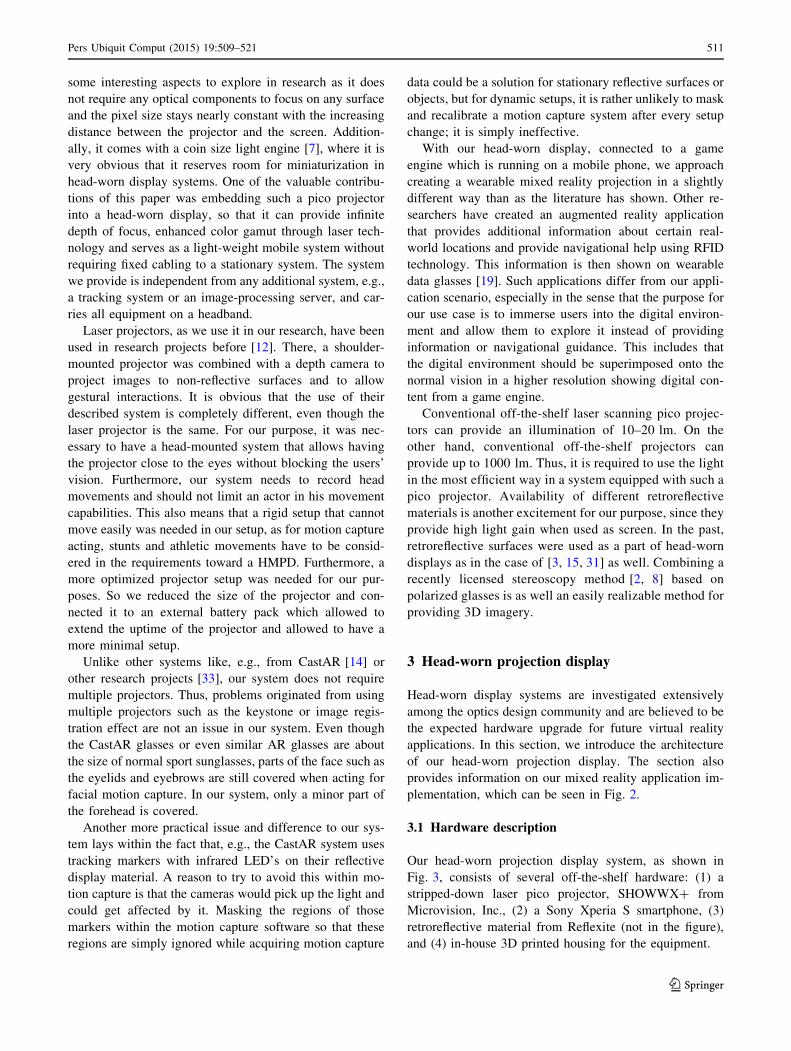
plementation, which can be seen in Fig. 2.
3.1 Hardware description
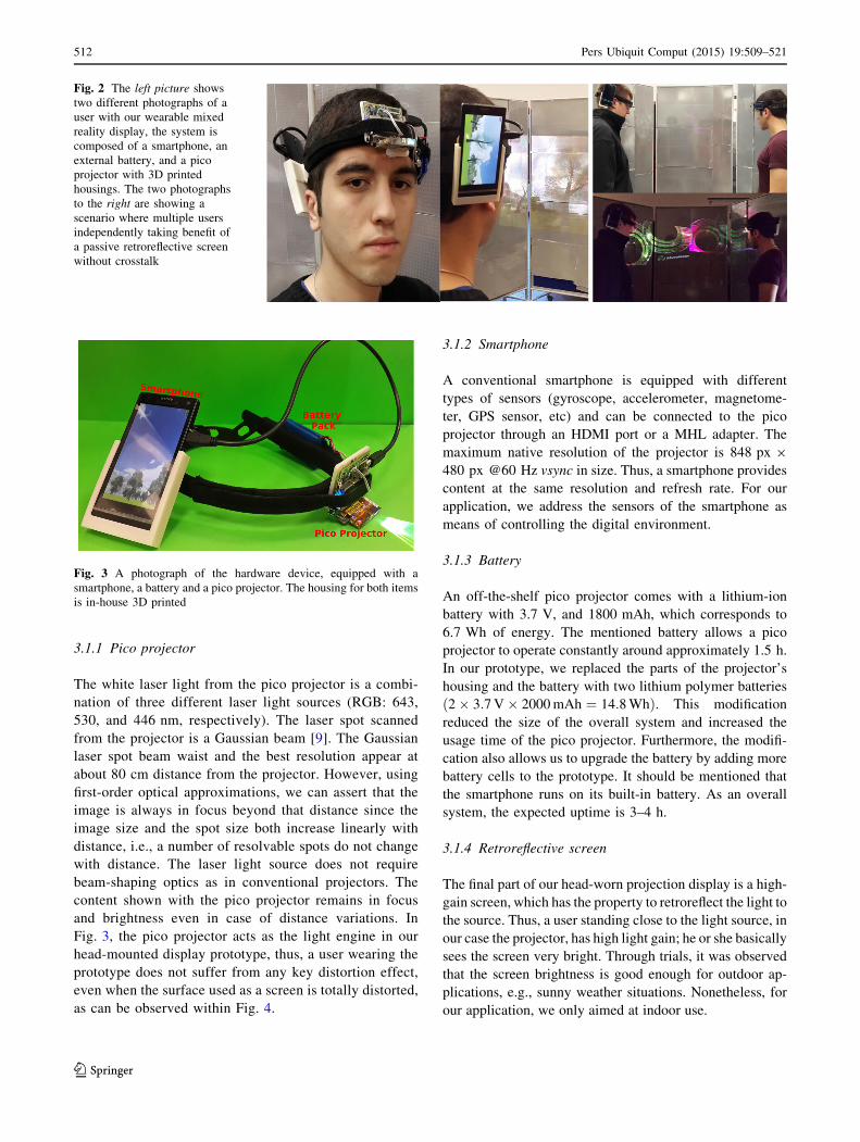
Our head-worn projection display system, as shown in
Fig. 3, consists of several off-the-shelf hardware: (1) a
stripped-down laser pico projector, SHOWWX? from
Microvision, Inc., (2) a Sony Xperia S smartphone, (3)
retroreflective material from Reflexite (not in the figure),
and (4) in-house 3D printed housing for the equipment.
Pers Ubiquit Comput (2015) 19:509–521 511
123
3.1.1 Pico projector
The white laser light from the pico projector is a combi-
nation of three different laser light sources (RGB: 643,
530, and 446 nm, respectively). The laser spot scanned
from the projector is a Gaussian beam [9]. The Gaussian
laser spot beam waist and the best resolution appear at
about 80 cm distance from the projector. However, using
first-order optical approximations, we can assert that the
image is always in focus beyond that distance since the
image size and the spot size both increase linearly with
distance, i.e., a number of resolvable spots do not change
with distance. The laser light source does not require
beam-shaping optics as in conventional projectors. The
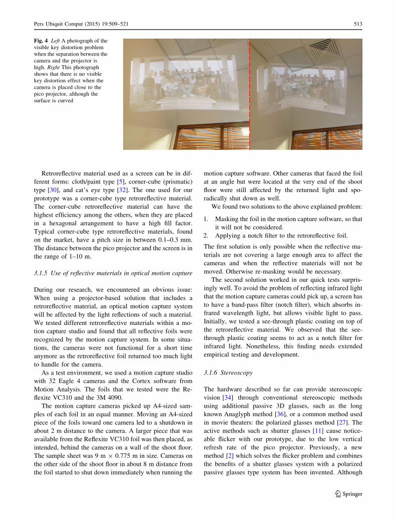
content shown with the pico projector remains in focus
and brightness even in case of distance variations. In
Fig. 3, the pico projector acts as the light engine in our
head-mounted display prototype, thus, a user wearing the
prototype does not suffer from any key distortion effect,
even when the surface used as a screen is totally distorted,
as can be observed within Fig. 4.
3.1.2 Smartphone
A conventional smartphone is equipped with different
types of sensors (gyroscope, accelerometer, magnetome-
ter, GPS sensor, etc) and can be connected to the pico
projector through an HDMI port or a MHL adapter. The
maximum native resolution of the projector is 848 px 9
480 px @60 Hz vsync in size. Thus, a smartphone provides
content at the same resolution and refresh rate. For our
application, we address the sensors of the smartphone as
means of controlling the digital environment.
3.1.3 Battery
An off-the-shelf pico projector comes with a lithium-ion
battery with 3.7 V, and 1800 mAh, which corresponds to
6.7 Wh of energy. The mentioned battery allows a pico
projector to operate constantly around approximately 1.5 h.
In our prototype, we replaced the parts of the projector’s
housing and the battery with two lithium polymer batteries
ð2 � 3:7 V � 2000 mAh ¼ 14:8 WhÞ. This modification
reduced the size of the overall system and increased the
usage time of the pico projector. Furthermore, the modifi-
cation also allows us to upgrade the battery by adding more
battery cells to the prototype. It should be mentioned that
the smartphone runs on its built-in battery. As an overall
system, the expected uptime is 3–4 h.
3.1.4 Retroreflective screen
The final part of our head-worn projection display is a high-
gain screen, which has the property to retroreflect the light to
the source. Thus, a user standing close to the light source, in
our case the projector, has high light gain; he or she basically
sees the screen very bright. Through trials, it was observed
that the screen brightness is good enough for outdoor ap-
plications, e.g., sunny weather situations. Nonetheless, for
our application, we only aimed at indoor use.
Fig. 2 The left picture shows
two different photographs of a
user with our wearable mixed
reality display, the system is
composed of a smartphone, an
external battery, and a pico
projector with 3D printed
housings. The two photographs
to the right are showing a
scenario where multiple users
independently taking benefit of
a passive retroreflective screen
without crosstalk
Fig. 3 A photograph of the hardware device, equipped with a
smartphone, a battery and a pico projector. The housing for both items
is in-house 3D printed
512 Pers Ubiquit Comput (2015) 19:509–521
123
Retroreflective material used as a screen can be in dif-
ferent forms: cloth/paint type [5], corner-cube (prismatic)
type [30], and cat’s eye type [32]. The one used for our
prototype was a corner-cube type retroreflective material.
The corner-cube retroreflective material can have the
highest efficiency among the others, when they are placed
in a hexagonal arrangement to have a high fill factor.
Typical corner-cube type retroreflective materials, found
on the market, have a pitch size in between 0.1–0.3 mm.
The distance between the pico projector and the screen is in
the range of 1–10 m.
3.1.5 Use of reflective materials in optical motion capture
During our research, we encountered an obvious issue:
When using a projector-based solution that includes a
retroreflective material, an optical motion capture system
will be affected by the light reflections of such a material.
We tested different retroreflective materials within a mo-
tion capture studio and found that all reflective foils were
recognized by the motion capture system. In some situa-
tions, the cameras were not functional for a short time
anymore as the retroreflective foil returned too much light
to handle for the camera.
As a test environment, we used a motion capture studio
with 32 Eagle 4 cameras and the Cortex software from
Motion Analysis. The foils that we tested were the Re-
flexite VC310 and the 3M 4090.
The motion capture cameras picked up A4-sized sam-
ples of each foil in an equal manner. Moving an A4-sized
piece of the foils toward one camera led to a shutdown in
about 2 m distance to the camera. A larger piece that was
available from the Reflexite VC310 foil was then placed, as
intended, behind the cameras on a wall of the shoot floor.
The sample sheet was 9 m 9 0.775 m in size. Cameras on
the other side of the shoot floor in about 8 m distance from
the foil started to shut down immediately when running the
motion capture software. Other cameras that faced the foil
at an angle but were located at the very end of the shoot
floor were still affected by the returned light and spo-
radically shut down as well.
We found two solutions to the above explained problem:
1. Masking the foil in the motion capture software, so that
it will not be considered.
2. Applying a notch filter to the retroreflective foil.
The first solution is only possible when the reflective ma-
terials are not covering a large enough area to affect the
cameras and when the reflective materials will not be
moved. Otherwise re-masking would be necessary.
The second solution worked in our quick tests surpris-
ingly well. To avoid the problem of reflecting infrared light
that the motion capture cameras could pick up, a screen has
to have a band-pass filter (notch filter), which absorbs in-
frared wavelength light, but allows visible light to pass.
Initially, we tested a see-through plastic coating on top of
the retroreflective material. We observed that the see-
through plastic coating seems to act as a notch filter for
infrared light. Nonetheless, this finding needs extended
empirical testing and development.
3.1.6 Stereoscopy
The hardware described so far can provide stereoscopic
vision [34] through conventional stereoscopic methods
using additional passive 3D glasses, such as the long
known Anaglyph method [36], or a common method used
in movie theaters: the polarized glasses method [27]. The
active methods such as shutter glasses [11] cause notice-
able flicker with our prototype, due to the low vertical
refresh rate of the pico projector. Previously, a new
method [2] which solves the flicker problem and combines
the benefits of a shutter glasses system with a polarized
passive glasses type system has been invented. Although
Fig. 4 Left A photograph of the
visible key distortion problem
when the separation between the
camera and the projector is
high. Right This photograph
shows that there is no visible
key distortion effect when the
camera is placed close to the
pico projector, although the
surface is curved
Pers Ubiquit Comput (2015) 19:509–521 513
123
the method has an active component (a liquid crystal po-
larization rotator) mounted on the projector, it works
without any noticeable flicker in pico projectors that have
low refresh rates. The method requires the screen to be
polarization maintaining. To make our prototype stereo-
scopic using the mentioned technique, a polarization rota-
tor has to be mounted on the photonics module of the pico
projector. Additionally, the user has to wear polarized
passive glasses or contact lenses. Currently, our system
does not provide 3D imagery, but with the modifications
mentioned, it is possible to provide 3D imagery.
3.2 Software description
As software development environment, the Unity 4 engine,
which is widely used in industry and research, was chosen
for our prototype. One requirement for the software was to
be able to create and change digital environments that will
be shown to actors in a quick way and by allowing to use
file formats that are common in computer games creation
and entertainment applications. Another requirement to be
considered was that the built-in sensors of our prototype
such as gyroscope and accelerometer were meant to be
used to control the digital environment. These decisions
limited our choice to a few game engines that support
mobile phone game development. As the Unity 4 game
engine is a cross-platform and state-of-the-art game engine,
our decision was to use it to develop our software. To
develop the software and create the digital environment,
we used Unity 4.3.1f1 by compiling the software to an
Android phone (tested phones: Samsung Galaxy S4?, S4,
S4 mini, S3, and Sony Xperia S).
Furthermore, we implemented controls to make the
environment exploreable through using the gyroscope
reacting to the movements of the phone, which can be
mounted in different positions on the head of a user (back-
head, top-head, and side-head). The accelerometer was
used to determine the steps and the direction of movement
of a user. In places where there is limited space to walk, a
solution based on walk-in-place [20] was also imple-
mented as an option. Note that multiple users using
multiple prototypes can run the same software indepen-
dently, but our software does not provide any synchro-
nization between the users at this moment. Head rotations,
independent from the phone’s mounting position, and
walk-in-place movements look accurate so that exploring
a digital environment is possible.
For testing purposes and also to allow switching sce-
narios and scenes quickly without reconfiguring or loading
new digital environments, we added the feature of
switching to different locations or scenes within the envi-
ronment so that, e.g., for motion capture shoots, scenes can
be switched in an instance and in real-time.
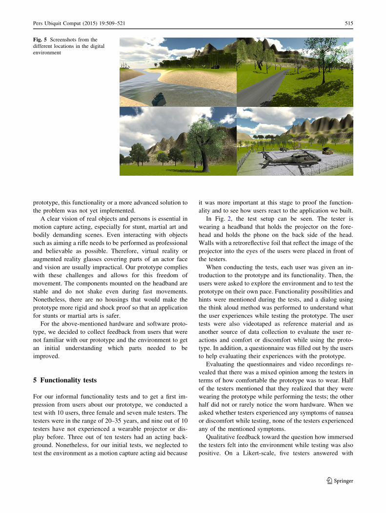
In Fig. 5, the four locations that were implemented for
testing and exploring our digital environment are depicted.
To create the digital environment, a height map of an island
was taken and modified to get the basic layout of the digital
environment. Used content and textures to create the en-
vironment are freely accessible on the Internet or through
the Unity Asset Store.
The created scenarios depicted in Fig. 5 were created to
serve as a basis to test our prototype. To provide a slightly
better perception of a more realistic environment, trees are
animated through shadows and reactions to wind; water is
animated through reoccurring wave cycles.
4 Application of the prototype in motion capture
Using our prototype in a motion capture studio revealed a
few challenges and questions to be solved. We already
mentioned the issue of a reflective material in a motion
capture studio above, but we also have to mention that
motion capture cameras can detect the light source of the
pico projector as well. Even though this is true, we found
that it is a fairly weak signal and mostly detected as noise
in the motion capture system. As many motion capture
shoots use skeletons and animation rigs to connect and
mask the markers mounted on an actor, the detected light
from the projector could even be neglected. Nonetheless, a
better solution is to slightly decrease the sensitivity of the
marker detection so that the motion capture system already
filters the light from the projector.
Emitting light from the projector into the motion capture
cameras could lead to a temporary malfunction of a cam-
era. In our brief tests, this only happened when the pro-
jector is facing the camera directly and from a short
distance (\2 m). The capture of motions is not affected
directly in such a situation because the motion capture
system calculates the marker positions from multiple
cameras and angles.
Acting for motion capture could mean that one or
multiple actors need to act and interact at the same time.
When using our HMPD, light is constantly emitted. As the
projector only has 15 lm, other actors or persons on the
shoot floor are not blinded when further away than 3 m.
Nonetheless, there is an issue when two actors face each
other directly, e.g., when having a dialog. Then the pro-
jectors would blind the actors and possibly interfere with
facial motion capture recordings. This is a very specific but
certainly occurring scenario and needs to be considered and
further explored. One solution could be to simply stop
projecting when actors face each other. An additionally
head-mounted camera, detecting the presence of another
user’s face could be used for this which then only projects
black pixels in regions of another user’s face. In our
514 Pers Ubiquit Comput (2015) 19:509–521
123
prototype, this functionality or a more advanced solution to
the problem was not yet implemented.
A clear vision of real objects and persons is essential in
motion capture acting, especially for stunt, martial art and
bodily demanding scenes. Even interacting with objects
such as aiming a rifle needs to be performed as professional
and believable as possible. Therefore, virtual reality or
augmented reality glasses covering parts of an actor face
and vision are usually impractical. Our prototype complies
with these challenges and allows for this freedom of
movement. The components mounted on the headband are
stable and do not shake even during fast movements.
Nonetheless, there are no housings that would make the
prototype more rigid and shock proof so that an application
for stunts or martial arts is safer.
For the above-mentioned hardware and software proto-
type, we decided to collect feedback from users that were
not familiar with our prototype and the environment to get
an initial understanding which parts needed to be
improved.
5 Functionality tests
For our informal functionality tests and to get a first im-
pression from users about our prototype, we conducted a
test with 10 users, three female and seven male testers. The
testers were in the range of 20–35 years, and nine out of 10
testers have not experienced a wearable projector or dis-
play before. Three out of ten testers had an acting back-
ground. Nonetheless, for our initial tests, we neglected to
test the environment as a motion capture acting aid because
it was more important at this stage to proof the function-
ality and to see how users react to the application we built.
In Fig. 2, the test setup can be seen. The tester is
wearing a headband that holds the projector on the fore-
head and holds the phone on the back side of the head.
Walls with a retroreflective foil that reflect the image of the
projector into the eyes of the users were placed in front of
the testers.
When conducting the tests, each user was given an in-
troduction to the prototype and its functionality. Then, the
users were asked to explore the environment and to test the
prototype on their own pace. Functionality possibilities and
hints were mentioned during the tests, and a dialog using
the think aloud method was performed to understand what
the user experiences while testing the prototype. The user
tests were also videotaped as reference material and as
another source of data collection to evaluate the user re-
actions and comfort or discomfort while using the proto-
type. In addition, a questionnaire was filled out by the users
to help evaluating their experiences with the prototype.
Evaluating the questionnaires and video recordings re-
vealed that there was a mixed opinion among the testers in
terms of how comfortable the prototype was to wear. Half
of the testers mentioned that they realized that they were
wearing the prototype while performing the tests; the other
half did not or rarely notice the worn hardware. When we
asked whether testers experienced any symptoms of nausea
or discomfort while testing, none of the testers experienced
any of the mentioned symptoms.
Qualitative feedback toward the question how immersed
the testers felt into the environment while testing was also
positive. On a Likert-scale, five testers answered with
Fig. 5 Screenshots from the
different locations in the digital
environment
Pers Ubiquit Comput (2015) 19:509–521 515
123
‘‘fully immersed’’ and five with ‘‘immersed.’’ When we
asked how realistic the environment felt, we need to report
that the testers gave a fairly mediocre feedback. The reason
for this lies within the fact that (1) the reflection area and
exploreable space need to be enlarged and (2) the walking
algorithm and the perception of movements in the digital
environment need to be improved as well.
The general feedback from the tests we performed was
positive and the testers showed interest in the application.
When we asked the testers whether they could imagine
using this application for private entertainment or training
purposes, four testers answered on a Likert-scale with
‘‘strongly agree,’’ three testers answered with ‘‘agree,’’ and
three with ‘‘undecided.’’
Testing the prototype has also shown that the phone’s
sensors do provide enough accuracy for simple navigation
and movements. The gyroscope accuracy used for head
movements was sufficient enough to provide smooth re-
actions when looking around in the digital world. On the
other hand, the accuracy of the phone’s built-in ac-
celerometer was quite limiting. Movements within the
digital world have been rather unreliable. Natural move-
ments were therefore not usable to create an immersive or
natural feel for navigation in the digital world. Simple
walk-in-place movements were possible to implement with
the accelerometer sensor. Using more accurate sensors or
even multiple sensors for navigation might be a way to
improve this for future applications. Furthermore, our tests
showed which parts of the application need to be improved
to create an even better experience, especially for future
work and entertainment applications.
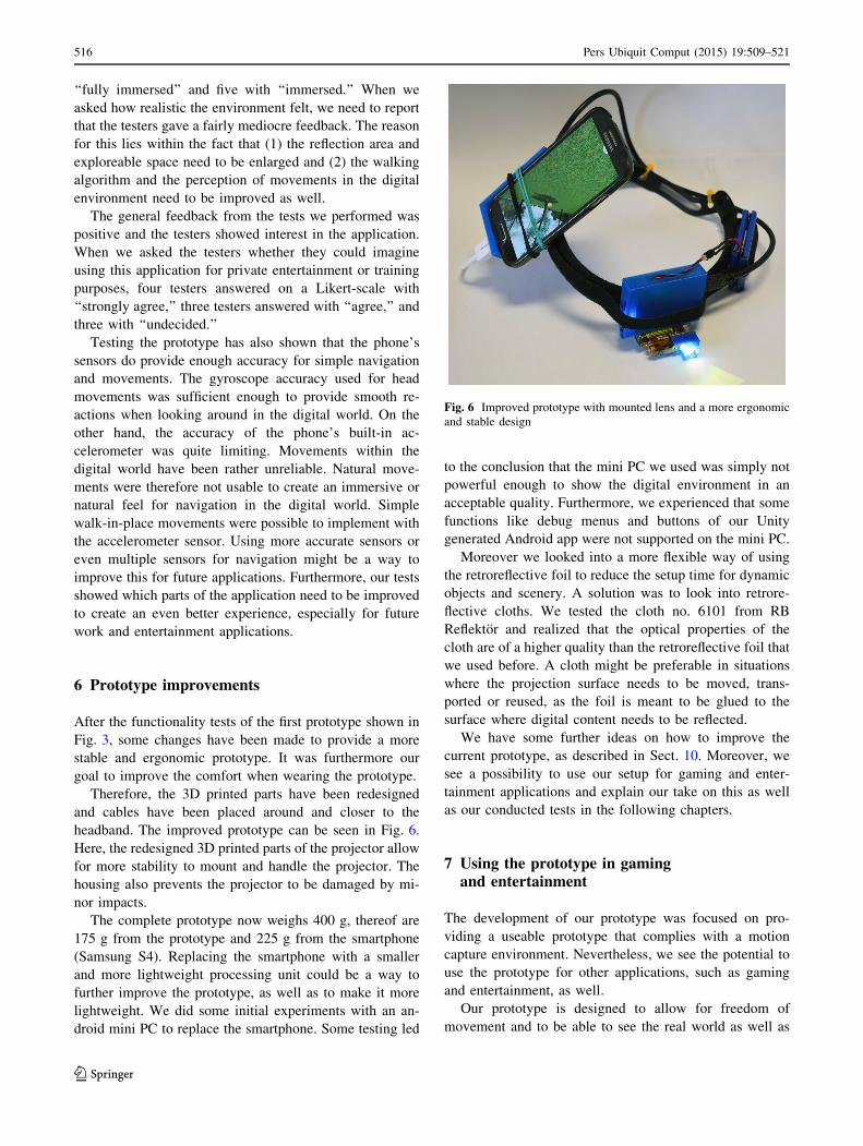
6 Prototype improvements
After the functionality tests of the first prototype shown in
Fig. 3, some changes have been made to provide a more
stable and ergonomic prototype. It was furthermore our
goal to improve the comfort when wearing the prototype.
Therefore, the 3D printed parts have been redesigned
and cables have been placed around and closer to the
headband. The improved prototype can be seen in Fig. 6.
Here, the redesigned 3D printed parts of the projector allow
for more stability to mount and handle the projector. The
housing also prevents the projector to be damaged by mi-
nor impacts.
The complete prototype now weighs 400 g, thereof are
175 g from the prototype and 225 g from the smartphone
(Samsung S4). Replacing the smartphone with a smaller
and more lightweight processing unit could be a way to
further improve the prototype, as well as to make it more
lightweight. We did some initial experiments with an an-
droid mini PC to replace the smartphone. Some testing led
to the conclusion that the mini PC we used was simply not
powerful enough to show the digital environment in an
acceptable quality. Furthermore, we experienced that some
functions like debug menus and buttons of our Unity
generated Android app were not supported on the mini PC.
Moreover we looked into a more flexible way of using
the retroreflective foil to reduce the setup time for dynamic
objects and scenery. A solution was to look into retrore-
flective cloths. We tested the cloth no. 6101 from RB
Reflektor and realized that the optical properties of the
cloth are of a higher quality than the retroreflective foil that
we used before. A cloth might be preferable in situations
where the projection surface needs to be moved, trans-
ported or reused, as the foil is meant to be glued to the
surface where digital content needs to be reflected.
We have some further ideas on how to improve the
current prototype, as described in Sect. 10. Moreover, we
see a possibility to use our setup for gaming and enter-
tainment applications and explain our take on this as well
as our conducted tests in the following chapters.
7 Using the prototype in gamingand entertainment
The development of our prototype was focused on pro-
viding a useable prototype that complies with a motion
capture environment. Nevertheless, we see the potential to
use the prototype for other applications, such as gaming
and entertainment, as well.
Our prototype is designed to allow for freedom of
movement and to be able to see the real world as well as
Fig. 6 Improved prototype with mounted lens and a more ergonomic
and stable design
516 Pers Ubiquit Comput (2015) 19:509–521
123
the virtual world. Therefore, we see the application area in
games where movements and body interactions are of
importance or games and entertainment applications that
allow exploring digital environments. These kinds of ap-
plications seem to be suitable as the projected image fol-
lows the head movements of the users and creates a natural
demand to use and experience the environment around the
users.
Game and entertainment experiences could be made
fairly immersive, especially when real-world objects like,
e.g., racquets, balls or similar, can be used to steer and
control the play.
Even multiple users could play with or against each
other, as the retroreflective screen allows using the same
projection surface for multiple users, even with different
content. This works without crosstalk. In a gaming context,
it could be a great opportunity to allow for co-op, strategy
or sports games. One player cannot see the content of the
other player, only when this is digitally projected. The laser
pico projector that we used has 15 lm, and digital content
could be seen by other players or observers when the en-
vironment is fairly dark, under normal light conditions this
is not an issue. Crosstalk of projected content could occur
when two players stand behind each other looking at the
same screen with approximately the same body height. As
soon as tracking of players would be implemented to the
prototype, this problem might be solvable.
An issue that occurs currently and might even be an
issue in the before-mentioned multiplayer scenario is when
two players face and look at each other. The projectors
could in this case blind the opposing person. These chal-
lenges stay for future iterations and developments of our
prototype.
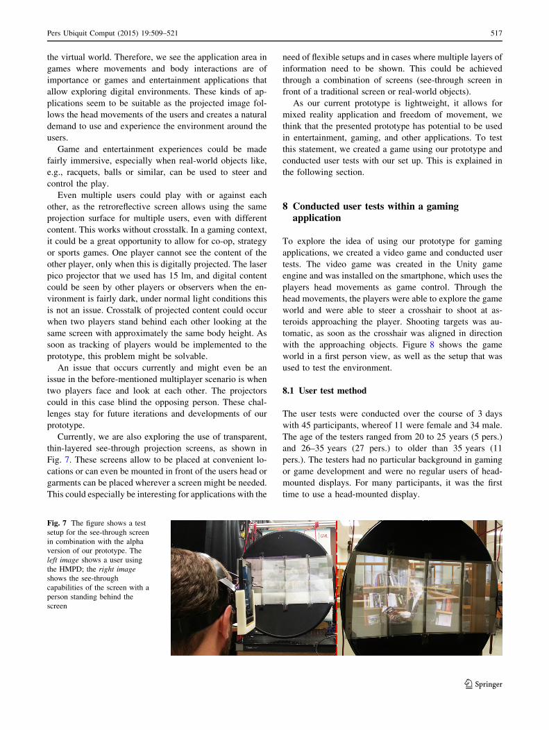
Currently, we are also exploring the use of transparent,
thin-layered see-through projection screens, as shown in
Fig. 7. These screens allow to be placed at convenient lo-
cations or can even be mounted in front of the users head or
garments can be placed wherever a screen might be needed.
This could especially be interesting for applications with the
need of flexible setups and in cases where multiple layers of
information need to be shown. This could be achieved
through a combination of screens (see-through screen in
front of a traditional screen or real-world objects).
As our current prototype is lightweight, it allows for
mixed reality application and freedom of movement, we
think that the presented prototype has potential to be used
in entertainment, gaming, and other applications. To test
this statement, we created a game using our prototype and
conducted user tests with our set up. This is explained in
the following section.
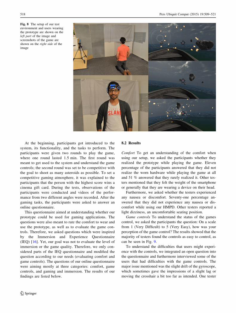
8 Conducted user tests within a gamingapplication
To explore the idea of using our prototype for gaming
applications, we created a video game and conducted user
tests. The video game was created in the Unity game
engine and was installed on the smartphone, which uses the
players head movements as game control. Through the
head movements, the players were able to explore the game
world and were able to steer a crosshair to shoot at as-
teroids approaching the player. Shooting targets was au-
tomatic, as soon as the crosshair was aligned in direction
with the approaching objects. Figure 8 shows the game
world in a first person view, as well as the setup that was
used to test the environment.
8.1 User test method
The user tests were conducted over the course of 3 days
with 45 participants, whereof 11 were female and 34 male.
The age of the testers ranged from 20 to 25 years (5 pers.)
and 26–35 years (27 pers.) to older than 35 years (11
pers.). The testers had no particular background in gaming
or game development and were no regular users of head-
mounted displays. For many participants, it was the first
time to use a head-mounted display.
Fig. 7 The figure shows a test
setup for the see-through screen
in combination with the alpha
version of our prototype. The
left image shows a user using
the HMPD; the right image
shows the see-through
capabilities of the screen with a
person standing behind the
screen
Pers Ubiquit Comput (2015) 19:509–521 517
123
At the beginning, participants got introduced to the
system, its functionality, and the tasks to perform. The
participants were given two rounds to play the game,
where one round lasted 1.5 min. The first round was
meant to get used to the system and understand the game
controls; the second round was set to be competitive with
the goal to shoot as many asteroids as possible. To set a
competitive gaming atmosphere, it was explained to the
participants that the person with the highest score wins a
cinema gift card. During the tests, observations of the
participants were conducted and videos of the perfor-
mance from two different angles were recorded. After the
gaming tasks, the participants were asked to answer an
online questionnaire.
This questionnaire aimed at understanding whether our
prototype could be used for gaming applications. The
questions were also meant to rate the comfort to wear and
use the prototype, as well as to evaluate the game con-
trols. Therefore, we asked questions which were inspired
by the Immersion and Experience Questionnaire
(IEQ) [16]. Yet, our goal was not to evaluate the level of
immersion or the game quality. Therefore, we only con-
sidered parts of the IEQ questionnaire and modified the
question according to our needs (evaluating comfort and
game controls). The questions of our online questionnaire
were aiming mostly at three categories: comfort, game
controls, and gaming and immersion. The results of our
findings are listed below.
8.2 Results
Comfort To get an understanding of the comfort when
using our setup, we asked the participants whether they
realized the prototype while playing the game. Eleven
percentage of the participants answered that they did not
realize the worn hardware while playing the game at all
and 51 % answered that they rarely realized it. Other tes-
ters mentioned that they felt the weight of the smartphone
or generally that they are wearing a device on their head.
Furthermore, we asked whether the testers experienced
any nausea or discomfort. Seventy-one percentage an-
swered that they did not experience any nausea or dis-
comfort while using our HMPD. Other testers reported a
light dizziness, an uncomfortable seating position.
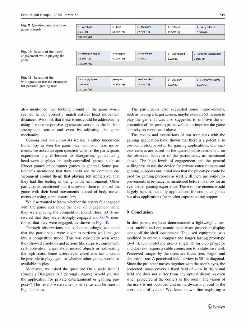
Game controls To understand the status of the games
control, we asked the participants the question: On a scale
from 1 (Very Difficult) to 5 (Very Easy), how was your
perception of the game control? The results showed that the
majority of testers found the controls as easy to control, as
can be seen in Fig. 9.
To understand the difficulties that users might experi-
ence with the controls, we integrated an open question into
the questionnaire and furthermore interviewed some of the
users that had difficulties with the game controls. The
major issue mentioned was the slight drift of the gyroscope,
which sometimes gave the impressions of a slight lag or
moving the crosshair a bit too far as intended. One tester
Fig. 8 The setup of our test
environment and users wearing
the prototype are shown on the
left part of the image and
screenshots of the game are
shown on the right side of the
image
518 Pers Ubiquit Comput (2015) 19:509–521
123
also mentioned that looking around in the game world
seemed to not correctly match natural head movement
distances. We think that these issues could be addressed by
using a more responsive gyroscope sensor as the built-in
smartphone sensor and even by adjusting the game
mechanics.
Gaming and immersion As we use a rather unconven-
tional way to steer the game play with your head move-
ments, we asked an open question whether the participants
experience any difference to Exergames, games using
head-worn displays or body-controlled games such as
Kinect games or computer games in general. Some par-
ticipants mentioned that they could see the complete en-
vironment around them; that playing felt immersive; that
they had the feeling of being in the environment. Other
participants mentioned that it is new to them to control the
game with their head movements instead of body move-
ments or using game controllers.
We also wanted to know whether the testers felt engaged
with the game and about the level of engagement while
they were playing the competition round. Here, 33 % an-
swered that they were strongly engaged and 60 % men-
tioned that they were engaged, as shown in Fig. 10.
Through observations and video recordings, we noted
that the participants were eager to perform well and got
into a competitive mood. This was especially seen when
they showed emotions and actions like surprise, enjoyment,
self-motivation, anger about missed objects or not beating
the high score. Some testers even asked whether it would
be possible to play again or whether other games would be
available to play.
Moreover, we asked the question: On a scale from 1
(Strongly Disagree) to 5 (Strongly Agree), would you use
the application for private entertainment or gaming pur-
poses? The results were rather positive, as can be seen in
Fig. 11 below.
The participants also suggested some improvements,
such as having a larger screen, maybe even a 360� screen to
play the game. It was also suggested to improve the er-
gonomics of the prototype, as well as to improve the game
controls, as mentioned above.
The results and evaluations of our user tests with the
gaming application have shown that there is a potential to
use our prototype setup for gaming applications. Our suc-
cess criteria are based on the questionnaire results and on
the observed behavior of the participants, as mentioned
above. The high levels of engagement and the general
willingness to use the device for private entertainment and
gaming, supports our initial idea that the prototype could be
used for gaming purposes as well. Still there are some im-
provements to be made, as mentioned before, to allow for an
even better gaming experience. These improvements would
largely benefit, not only applications for computer games
but also applications for motion capture acting support.
9 Conclusion
In this paper, we have demonstrated a lightweight, low-
cost, mobile and ergonomic head-worn projection display
using off-the-shelf equipment. The used equipment was
modified to create a compact and longer lasting prototype
(3–4 h). Our prototype uses a single 15 lm pico projector
and does not require a cable connection to a stationary unit.
Perceived images by the users are focus free, bright, and
distortion free. A perceived field of view is 50� in diagonal.
Since the projector moves together with the user’s eyes, the
projected image covers a fixed field of view in the visual
field and does not suffer from any optical distortion even
when projected at the corners of the room. The vision of
the users is not occluded and no hardware is placed in the
users field of vision. We have shown that exploring a
Fig. 9 Questionnaire results on
game controls
Fig. 10 Results of the users’
engagement while playing the
game
Fig. 11 Results of the
willingness to use the prototype
for personal gaming uses
Pers Ubiquit Comput (2015) 19:509–521 519
123
virtual environment is possible with our prototype and al-
lows to create a fairly immersive experience. Multiple
users can independently use the screen without experi-
encing crosstalk. Moreover, we discussed and tested the
usage of our prototype for gaming applications. Our pro-
totype is an inexpensive, lightweight, and stand-alone MR
HMPD that shows the potential to be used in motion
capture studios as well as in other gaming and entertain-
ment applications. This is especially the case because the
system is mobile and not dependent on external tracking,
computing, or displaying systems.
10 Future improvements
As our goal is to use the prototype for motion capture
acting aid and possibly other entertainment applications, a
few improvements and changes need to be done to allow
the use of the prototype for such environments. Improving
the controls and walking algorithms of the prototype
through better sensor data needs to be performed to get a
more precise and natural feel. Using different and possibly
multiple inertial sensors is a current idea to solve this issue.
Therefore we are developing wireless, battery-driven in-
ertial sensors hosting an accelerometer and gyroscope.
Another improvement that we are planning to address is
to replace the smartphone with a smaller and more light-
weight processing unity. Many functions of the smartphone
are not used and can therefore be neglected.
Testing and improving the prototype’s physical rigid-
ness need to be done to allow wearing the prototype for
stunt motion capture shoots as well as to make the proto-
type even more ergonomic and rigid.
The next version of the software is expected to provide
interaction in between multiple users sharing the same
digital content. Alternatively, there can be multiple screens
used and shared by multiple users in remote locations.
Acknowledgments On behalf of Malardalen University, we would
like to thank KKS Stiftelsen for their support of the Industrial Re-
search School, ITS-EASY. On behalf of Koc University, we would
like to thank the Scientific and Technological Research Council of
Turkey (TUBITAK) with their support in Project No. 111E183.
References
1. Aksit K, Kade D, Ozcan O, Urey H (2014) Head-worn mixed
reality projection display application. In: Proceedings of ACE
2014, 11th advances in computer entertainment conference. ACM
2. Aksit K, Eldes O, Viswanathan S, Freeman MO, Urey H (2012)
Portable 3D laser projector using mixed polarization technique.
J Disp Technol 8(10):582–589
3. Bolas M, Krum DM (2010) Augmented reality applications and
user interfaces using head-coupled near-axis personal projectors
with novel retroreflective props and surfaces. In: Pervasive 2010
Ubiprojection workshop
4. Cakmakci O, Rolland J (2006) Head-worn displays: a review.
J Disp Technol 2(3):199–216
5. DeMaster RD (1977) Low-profile raised retroreflective pavement
marker. US Patent 4,035,059
6. Firth N (2013) First wave of virtual reality games will let you live
the dream. New Sci 218(2922):19–20
7. Freeman M, Champion M, Madhavan S (2009) Scanned laser
pico-projectors: seeing the big picture (with a small device). Opt
Photonics News 20(5):28–34
8. Freeman MO, Viswanathan SP, Lashmet D (2013) Mixed po-
larization imaging system for three-dimensional projection and
corresponding methods. US Patent 20,130,038,837
9. Goodman JW, Gustafson SC (1996) Introduction to fourier op-
tics. Opt Eng 35(5):1513–1513
10. Guillaumee M, Vahdati SP, Tremblay E, Mader A, Bernasconi G,
Cadarso VJ, Grossenbacher J, Brugger J, Sprague R, Moser C
(2014) Curved holographic combiner for color head worn display.
J Disp Technol 10(6):444–449
11. Hammond L (1924) Stereoscopic motion-eectuke device. US
Patent 1,506,524
12. Harrison C, Benko H, Wilson AD (2011) Omnitouch: wearable
multitouch interaction everywhere. In: Proceedings of the 24th
annual ACM symposium on user interface software and tech-
nology. ACM, pp 441–450
13. Hua H, Gao C, Rolland JP (2002) Imaging properties of retro-
reflective materials used in head-mounted projective displays
(HMPDs). In: AeroSense 2002. International Society for Optics
and Photonics, pp 194–201
14. Illusions T (2014) Castar. http://technicalillusions.com/castar/
15. Inami M, Kawakami N, Sekiguchi D, Yanagida Y, Maeda T,
Tachi S (2000) Visuo-haptic display using head-mounted pro-
jector. In: Virtual reality, 2000. Proceedings. IEEE, pp 233–240.
doi:10.1109/VR.2000.840503
16. Jennett C, Cox AL, Cairns P, Dhoparee S, Epps A, Tijs T, Walton
A (2008) Measuring and defining the experience of immersion in
games. Int J Hum Comput Stud 66(9):641–661
17. Kade D, Ozcan O, Lindell R (2013) An immersive motion cap-
ture environment. In: Proceedings of the ICCGMAT 2013, in-
ternational conference on computer games, multimedia and allied
technology. World Academy of Science, Engineering and Tech-
nology, pp 500–506
18. Kade D, Ozcan O, Lindell R (2013) Towards Stanislavski-based
principles for motion capture acting in animation and computer
games. In: Proceedings of CONFIA 2013, international confer-
ence in illustration and animation. IPCA, pp 277–292
19. Kanbara RTM, Yokoya N (2003) A wearable augmented reality
system using positioning infrastructures and a pedometer. In:
Proceedings of the seventh IEEE international symposium on
wearable computers (ISWC03), vol 1530, pp 17–00
20. Kim JS, Gracanin D, Quek F (2012) Sensor-fusion walking-in-
place interaction technique using mobile devices. In: Virtual re-
ality workshops (VR), 2012 IEEE. IEEE, pp 39–42
21. Martins R, Shaoulov V, Ha Y, Rolland J (2007) A mobile
head-worn projection display. Opt Express 15(22):14530–
14538
22. Mistry P, Maes P (2009) Sixthsense: a wearable gestural inter-
face. In: ACM SIGGRAPH ASIA 2009 Sketches. ACM, p 11
23. Mistry P, Maes P, Chang L (2009) WUW-wear Ur world: a
wearable gestural interface. In: CHI’09 extended abstracts on
Human factors in computing systems. ACM, pp 4111–4116
24. Moeslund TB, Hilton A, Kruger V (2006) A survey of advances
in vision-based human motion capture and analysis. Comput Vis
Image Underst 104(2):90–126
520 Pers Ubiquit Comput (2015) 19:509–521
123
25. Olsson MI, Heinrich MJ, Kelly D, Lapetina J (2013) Wear-
able device with input and output structures. US Patent
20,130,044,042
26. Pascu T, White M, Patoli Z (2013) Motion capture and activity
tracking using Smartphone-driven body sensor networks. In: In-
novative computing technology (INTECH), 2013 third interna-
tional conference on. IEEE, pp 456–462
27. Pictet L (1924) Device for projecting and viewing stereoscopic
pictures. US Patent 1,503,766
28. Rolland J, Thompson K (2011) See-through head worn displays
for mobile augmented reality. In: Proceedings of the China na-
tional computer conference
29. Rolland JP, Thompson KP, Urey H, Thomas M (2012) See-
through head worn display (HWD) architectures. In: Handbook of
visual display technology. Springer, Berlin, pp 2145–2170
30. Scholl MS (1995) Ray trace through a corner-cube retroreflector
with complex reflection coefficients. JOSA A 12(7):1589–1592
31. Smits G, Kikinis D (2013) System and method for 3-D projection
and enhancements for interactivity. https://www.google.com/
patents/US20130300637. US Patent App. 13/877,652
32. Snyder J (1975) Paraxial ray analysis of a cats-eye retroreflector.
Appl Opt 14(8):1825–1828
33. Sonoda T, Endo T, Kawakami N, Tachi S (2005) X’talvisor: full
open type head-mounted projector. In: ACM SIGGRAPH 2005
emerging technologies. ACM, p 32
34. Urey H, Chellappan KV, Erden E, Surman P (2011) State of the
art in stereoscopic and autostereoscopic displays. Proc IEEE
99(4):540–555
35. Vlasic D, Adelsberger R, Vannucci G, Barnwell J, Gross M,
Matusik W, Popovic J (2007) Practical motion capture in ev-
eryday surroundings. ACM Trans Graph 26(3). doi:10.1145/
1276377.1276421
36. Watch AF (1895) The anaglyph: a new method of producing the
stereoscopic effect. J Frankl Inst 140(6):401–419
Pers Ubiquit Comput (2015) 19:509–521 521
123