Embed Size (px)
Citation preview
8/15/2019 Head and Neck Anatomy for Dental Medicine - Thieme; (January 26, 2010)
http://slidepdf.com/reader/full/head-and-neck-anatomy-for-dental-medicine-thieme-january-26-2010 1/384
MediaCenter.thieme.com
plus e-content online
8/15/2019 Head and Neck Anatomy for Dental Medicine - Thieme; (January 26, 2010)
http://slidepdf.com/reader/full/head-and-neck-anatomy-for-dental-medicine-thieme-january-26-2010 2/384
Head and Neck Anatomy forDental Medicine
8/15/2019 Head and Neck Anatomy for Dental Medicine - Thieme; (January 26, 2010)
http://slidepdf.com/reader/full/head-and-neck-anatomy-for-dental-medicine-thieme-january-26-2010 3/384
8/15/2019 Head and Neck Anatomy for Dental Medicine - Thieme; (January 26, 2010)
http://slidepdf.com/reader/full/head-and-neck-anatomy-for-dental-medicine-thieme-january-26-2010 4/384
Head and Neck Anatomy forDental Medicine
Based on the work of
Michael SchuenkeErik SchulteUdo Schumacher
Illustrations by
Markus Voll
Karl Wesker
Edited by
Eric W. Baker
Thieme
New York · Stuttgart
8/15/2019 Head and Neck Anatomy for Dental Medicine - Thieme; (January 26, 2010)
http://slidepdf.com/reader/full/head-and-neck-anatomy-for-dental-medicine-thieme-january-26-2010 5/384
Developmental Editor: Bridget N. Queenan and Julie O’MearaEditorial Director, Educational Products: Cathrin Weinstein, MD, and
Anne T. Vinnicombe
Associate Manager, Book Production: Adelaide Elsie Starbecker
International Production Director: Andreas Schabert
Director of Sales: Ross Lumpkin
Vice President, International Marketing and Sales: Cornelia Schulze
Chief Financial Offi cer: James W. Mitos
President: Brian D. Scanlan
Illustrators: Markus Voll and Karl Wesker
Compositor: MPS Content Services, A Macmillan Company
Printer: Leo Paper Products Ltd.
Copyright © 2010 by Thieme Medical Publishers, Inc.
This book, including all parts thereof, is legally protected by copyright.Any use, exploitation, or commercialization outside the narrow limits set
by copyright legislation without the publisher’s consent is illegal and lia-
ble to prosecution. This applies in particular to photostat reproduction,
copying, mimeographing or duplication of any kind, translating, prepara-
tion of microfilms, and electronic data processing and storage.
Important note: Medical knowledge is ever-changing. As new research
and clinical experience broaden our knowledge, changes in treatment
and drug therapy may be required. The authors and editors of the mate-
rial herein have consulted sources believed to be reliable in their eff orts
to provide information that is complete and in accord with the stand-
ards accepted at the time of publication. However, in view of the pos-
sibility of human error by the authors, editors, or publisher of the work
herein or changes in medical knowledge, neither the authors, editors,
nor publisher, nor any other party who has been involved in the prepa-
ration of this work, warrants that the information contained herein is in
every respect accurate or complete, and they are not responsible for any
errors or omissions or for the results obtained from use of such infor-
mation. Readers are encouraged to confirm the information contained
herein with other sources. For example, readers are advised to check the
product information sheet included in the package of each drug they
plan to administer to be certain that the information contained in this
publication is accurate and that changes have not been made in the rec-
ommended dose or in the contraindications for administration. This rec-
ommendation is of particular importance in connection with new or
infrequently used drugs.
ISBN 978-1-60406-209-0
Thieme Medical Publishers, Inc.333 Seventh Avenue
New York, New York 10001
Based on the work of Michael Schuenke, MD, PhD, Erik Schulte, MD, and
Udo Schumacher, MD
Eric W. Baker, MA, MPhil
Educational Coordinator and Director of Human Gross Anatomy
Department of Basic Science and Craniofacial Biology
New York University College of Dentistry
New York, New York 10010
Michael Schuenke, MD, PhD
Institute of Anatomy
Christian Albrecht University KielOlshausenstrasse 40
D-24098 Kiel
Erik Schulte, MD
Department of Anatomy and Cell Biology
Johannes Gutenberg University
Saarstrasse 19-21
D-55099 Mainz
Udo Schumacher, MD, FRCPath, CBiol, FIBiol, DSc
Institute of Anatomy II: Experimental Morphology
Center for Experimental Medicine
University Medical Center Hamburg-Eppendorf
Martinistrasse 52
D-20246 Hamburg
Library of Congress Cataloging-in-Publication Data
Head and neck anatomy for dental medicine / edited by Eric W. Baker ;
based on the work of Michael Schuenke, Erik Schulte, Udo Schumacher ;
illustrations by Markus Voll, Karl Wesker.
p. ; cm.
Includes bibliographical references and index.
ISBN 978-1-60406-209-0 (softcover : alk. paper) 1. Head—Anatomy—
Atlases. 2. Neck—Anatomy—Atlases. I. Baker, Eric W. (Eric William),
1961– II. Schünke, Michael. III. Schulte, Erik. IV. Schumacher, Udo.
[DNLM: 1. Head—anatomy & histology—Atlases. 2. Dentistry—
Atlases. 3. Neck—anatomy & histology—Atlases. WE 17 H432 2010]
QM535.H43 2010 611’.910223--dc22
2009041592

8/15/2019 Head and Neck Anatomy for Dental Medicine - Thieme; (January 26, 2010)
http://slidepdf.com/reader/full/head-and-neck-anatomy-for-dental-medicine-thieme-january-26-2010 6/384
Dedication
To my wonderful wife, Amy Curran Baker, and my awe-inspiring daughters, Phoebe and Claire.
8/15/2019 Head and Neck Anatomy for Dental Medicine - Thieme; (January 26, 2010)
http://slidepdf.com/reader/full/head-and-neck-anatomy-for-dental-medicine-thieme-january-26-2010 7/384
To access additional material or resources available with this e-book, please visithttp://www.thieme.com/bonuscontent. After completing a short form to verify your e-bookpurchase, you will be provided with the instructions and access codes necessary to retrieveany bonus content.
8/15/2019 Head and Neck Anatomy for Dental Medicine - Thieme; (January 26, 2010)
http://slidepdf.com/reader/full/head-and-neck-anatomy-for-dental-medicine-thieme-january-26-2010 8/384
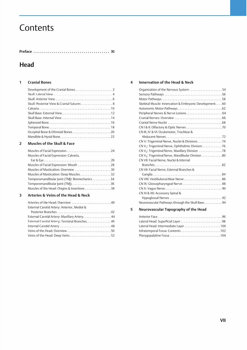
Contents
Head
1 Cranial Bones
Development of the Cranial Bones . . . . . . . . . . . . . . . . . . . . . . . 2
Skull: Lateral View . . . . . . . . . . . . . . . . . . . . . . . . . . . . . . . . . . . . 4
Skull: Anterior View . . . . . . . . . . . . . . . . . . . . . . . . . . . . . . . . . . . 6
Skull: Posterior View & Cranial Sutures . . . . . . . . . . . . . . . . . . . 8
Calvaria . . . . . . . . . . . . . . . . . . . . . . . . . . . . . . . . . . . . . . . . . . . . 10
Skull Base: External View . . . . . . . . . . . . . . . . . . . . . . . . . . . . . . 12
Skull Base: Internal View . . . . . . . . . . . . . . . . . . . . . . . . . . . . . . 14
Sphenoid Bone . . . . . . . . . . . . . . . . . . . . . . . . . . . . . . . . . . . . . . 16Temporal Bone . . . . . . . . . . . . . . . . . . . . . . . . . . . . . . . . . . . . . . 18
Occipital Bone & Ethmoid Bones . . . . . . . . . . . . . . . . . . . . . . . 20
Mandible & Hyoid Bone . . . . . . . . . . . . . . . . . . . . . . . . . . . . . . . 22
2 Muscles of the Skull & Face
Muscles of Facial Expression . . . . . . . . . . . . . . . . . . . . . . . . . . . 24
Muscles of Facial Expression: Calvaria,
Ear & Eye . . . . . . . . . . . . . . . . . . . . . . . . . . . . . . . . . . . . . . . . . 26
Muscles of Facial Expression: Mouth . . . . . . . . . . . . . . . . . . . . 28
Muscles of Mastication: Overview . . . . . . . . . . . . . . . . . . . . . . 30
Muscles of Mastication: Deep Muscles . . . . . . . . . . . . . . . . . . . 32
Temporomandibular Joint (TMJ): Biomechanics . . . . . . . . . . . 34
Temporomandibular Joint (TMJ) . . . . . . . . . . . . . . . . . . . . . . . . 36Muscles of the Head: Origins & Insertions . . . . . . . . . . . . . . . .38
3 Arteries & Veins of the Head & Neck
Arteries of the Head: Overview . . . . . . . . . . . . . . . . . . . . . . . . 40
External Carotid Artery: Anterior, Medial &
Posterior Branches . . . . . . . . . . . . . . . . . . . . . . . . . . . . . . . . .42
External Carotid Artery: Maxillary Artery . . . . . . . . . . . . . . . . . 44
External Carotid Artery: Terminal Branches . . . . . . . . . . . . . . . 46
Internal Carotid Artery . . . . . . . . . . . . . . . . . . . . . . . . . . . . . . . 48
Veins of the Head: Overview . . . . . . . . . . . . . . . . . . . . . . . . . . . 50
Veins of the Head: Deep Veins . . . . . . . . . . . . . . . . . . . . . . . . . 52
4 Innervation of the Head & Neck
Organization of the Nervous System . . . . . . . . . . . . . . . . . . . . 54
Sensory Pathways . . . . . . . . . . . . . . . . . . . . . . . . . . . . . . . . . . . 56
Motor Pathways . . . . . . . . . . . . . . . . . . . . . . . . . . . . . . . . . . . . . 58
Skeletal Muscle: Innervation & Embryonic Development . . . . 60
Autonomic Motor Pathways . . . . . . . . . . . . . . . . . . . . . . . . . . .62
Peripheral Nerves & Nerve Lesions . . . . . . . . . . . . . . . . . . . . . . 64
Cranial Nerves: Overview . . . . . . . . . . . . . . . . . . . . . . . . . . . . . 66
Cranial Nerve Nuclei . . . . . . . . . . . . . . . . . . . . . . . . . . . . . . . . . 68CN I & II: Olfactory & Optic Nerves . . . . . . . . . . . . . . . . . . . . . .70
CN III, IV & VI: Oculomotor, Trochlear &
Abducent Nerves . . . . . . . . . . . . . . . . . . . . . . . . . . . . . . . . . . 72
CN V: Trigeminal Nerve, Nuclei & Divisions . . . . . . . . . . . . . . . 74
CN V1: Trigeminal Nerve, Ophthalmic Division . . . . . . . . . . . .76
CN V2: Trigeminal Nerve, Maxillary Division . . . . . . . . . . . . . . 78
CN V3: Trigeminal Nerve, Mandibular Division . . . . . . . . . . . .80
CN VII: Facial Nerve, Nuclei & Internal
Branches . . . . . . . . . . . . . . . . . . . . . . . . . . . . . . . . . . . . . . . . .82
CN VII: Facial Nerve, External Branches &
Ganglia . . . . . . . . . . . . . . . . . . . . . . . . . . . . . . . . . . . . . . . . . . 84
CN VIII: Vestibulocochlear Nerve . . . . . . . . . . . . . . . . . . . . . . . 86
CN IX: Glossopharyngeal Nerve . . . . . . . . . . . . . . . . . . . . . . . . 88CN X: Vagus Nerve . . . . . . . . . . . . . . . . . . . . . . . . . . . . . . . . . . . 90
CN XI & XII: Accessory Spinal &
Hypoglossal Nerves . . . . . . . . . . . . . . . . . . . . . . . . . . . . . . . . 92
Neurovascular Pathways through the Skull Base . . . . . . . . . . . 94
5 Neurovascular Topography of the Head
Anterior Face . . . . . . . . . . . . . . . . . . . . . . . . . . . . . . . . . . . . . . . 96
Lateral Head: Superficial Layer . . . . . . . . . . . . . . . . . . . . . . . . . 98
Lateral Head: Intermediate Layer . . . . . . . . . . . . . . . . . . . . . . 100
Infratemporal Fossa: Contents . . . . . . . . . . . . . . . . . . . . . . . . 102
Pterygopalatine Fossa . . . . . . . . . . . . . . . . . . . . . . . . . . . . . . . 104
Preface . . . . . . . . . . . . . . . . . . . . . . . . . . . . . . . . . . . . . . XI
VII
8/15/2019 Head and Neck Anatomy for Dental Medicine - Thieme; (January 26, 2010)
http://slidepdf.com/reader/full/head-and-neck-anatomy-for-dental-medicine-thieme-january-26-2010 9/384
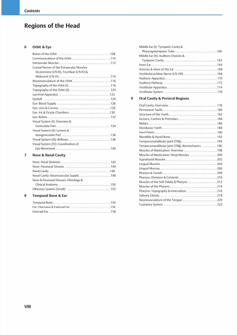
6 Orbit & Eye
Bones of the Orbit . . . . . . . . . . . . . . . . . . . . . . . . . . . . . . . . . .108
Communications of the Orbit . . . . . . . . . . . . . . . . . . . . . . . . . 110Extraocular Muscles . . . . . . . . . . . . . . . . . . . . . . . . . . . . . . . . . 112
Cranial Nerves of the Extraocular Muscles:
Oculomotor (CN III), Trochlear (CN IV) &
Abducent (CN VI) . . . . . . . . . . . . . . . . . . . . . . . . . . . . . . . . . 114
Neurovasculature of the Orbit . . . . . . . . . . . . . . . . . . . . . . . . 116
Topography of the Orbit (I) . . . . . . . . . . . . . . . . . . . . . . . . . . . 118
Topography of the Orbit (II) . . . . . . . . . . . . . . . . . . . . . . . . . . 120
Lacrimal Apparatus . . . . . . . . . . . . . . . . . . . . . . . . . . . . . . . . .122
Eyeball . . . . . . . . . . . . . . . . . . . . . . . . . . . . . . . . . . . . . . . . . . . 124
Eye: Blood Supply . . . . . . . . . . . . . . . . . . . . . . . . . . . . . . . . . . 126
Eye: Lens & Cornea. . . . . . . . . . . . . . . . . . . . . . . . . . . . . . . . . .128
Eye: Iris & Ocular Chambers . . . . . . . . . . . . . . . . . . . . . . . . . .130
Eye: Retina . . . . . . . . . . . . . . . . . . . . . . . . . . . . . . . . . . . . . . . . 132Visual System (I): Overview &
Geniculate Part . . . . . . . . . . . . . . . . . . . . . . . . . . . . . . . . . . . 134
Visual System (II): Lesions &
Nongeniculate Part . . . . . . . . . . . . . . . . . . . . . . . . . . . . . . . 136
Visual System (III): Reflexes . . . . . . . . . . . . . . . . . . . . . . . . . . . 138
Visual System (IV): Coordination of
Eye Movement . . . . . . . . . . . . . . . . . . . . . . . . . . . . . . . . . . . 140
7 Nose & Nasal Cavity
Nose: Nasal Skeleton . . . . . . . . . . . . . . . . . . . . . . . . . . . . . . . . 142
Nose: Paranasal Sinuses . . . . . . . . . . . . . . . . . . . . . . . . . . . . . 144
Nasal Cavity . . . . . . . . . . . . . . . . . . . . . . . . . . . . . . . . . . . . . . .146
Nasal Cavity: Neurovascular Supply . . . . . . . . . . . . . . . . . . . . 148Nose & Paranasal Sinuses: Histology &
Clinical Anatomy . . . . . . . . . . . . . . . . . . . . . . . . . . . . . . . . . 150
Olfactory System (Smell) . . . . . . . . . . . . . . . . . . . . . . . . . . . . 152
8 Temporal Bone & Ear
Temporal Bone . . . . . . . . . . . . . . . . . . . . . . . . . . . . . . . . . . . . . 154
Ear: Overview & External Ear . . . . . . . . . . . . . . . . . . . . . . . . . .156
External Ear . . . . . . . . . . . . . . . . . . . . . . . . . . . . . . . . . . . . . . . 158
Middle Ear (I): Tympanic Cavity &
Pharyngotympanic Tube . . . . . . . . . . . . . . . . . . . . . . . . . . .160
Middle Ear (II): Auditory Ossicles &
Tympanic Cavity . . . . . . . . . . . . . . . . . . . . . . . . . . . . . . . . . . 162
Inner Ear . . . . . . . . . . . . . . . . . . . . . . . . . . . . . . . . . . . . . . . . . .164
Arteries & Veins of the Ear . . . . . . . . . . . . . . . . . . . . . . . . . . . 166
Vestibulocochlear Nerve (CN VIII) . . . . . . . . . . . . . . . . . . . . . 168
Auditory Apparatus . . . . . . . . . . . . . . . . . . . . . . . . . . . . . . . . . 170
Auditory Pathway . . . . . . . . . . . . . . . . . . . . . . . . . . . . . . . . . . 172
Vestibular Apparatus . . . . . . . . . . . . . . . . . . . . . . . . . . . . . . . .174
Vestibular System . . . . . . . . . . . . . . . . . . . . . . . . . . . . . . . . . . 176
9 Oral Cavity & Perioral Regions
Oral Cavity: Overview . . . . . . . . . . . . . . . . . . . . . . . . . . . . . . . 178
Permanent Teeth . . . . . . . . . . . . . . . . . . . . . . . . . . . . . . . . . . . 180
Structure of the Teeth . . . . . . . . . . . . . . . . . . . . . . . . . . . . . . . 182
Incisors, Canines & Premolars . . . . . . . . . . . . . . . . . . . . . . . . . 184
Molars . . . . . . . . . . . . . . . . . . . . . . . . . . . . . . . . . . . . . . . . . . . . 186
Deciduous Teeth . . . . . . . . . . . . . . . . . . . . . . . . . . . . . . . . . . . 188
Hard Palate . . . . . . . . . . . . . . . . . . . . . . . . . . . . . . . . . . . . . . . . 190
Mandible & Hyoid Bone . . . . . . . . . . . . . . . . . . . . . . . . . . . . . . 192
Temporomandibular Joint (TMJ) . . . . . . . . . . . . . . . . . . . . . . . 194
Temporomandibular Joint (TMJ): Biomechanics . . . . . . . . . . 196
Muscles of Mastication: Overview . . . . . . . . . . . . . . . . . . . . . 198
Muscles of Mastication: Deep Muscles . . . . . . . . . . . . . . . . . . 200
Suprahyoid Muscles . . . . . . . . . . . . . . . . . . . . . . . . . . . . . . . . . 202
Lingual Muscles . . . . . . . . . . . . . . . . . . . . . . . . . . . . . . . . . . . . 204
Lingual Mucosa . . . . . . . . . . . . . . . . . . . . . . . . . . . . . . . . . . . . 206
Pharynx & Tonsils . . . . . . . . . . . . . . . . . . . . . . . . . . . . . . . . . . . 208
Pharynx: Divisions & Contents . . . . . . . . . . . . . . . . . . . . . . . . 210
Muscles of the Soft Palate & Pharynx . . . . . . . . . . . . . . . . . . .212
Muscles of the Pharynx . . . . . . . . . . . . . . . . . . . . . . . . . . . . . . 214
Pharynx: Topography & Innervation . . . . . . . . . . . . . . . . . . . . 216
Salivary Glands . . . . . . . . . . . . . . . . . . . . . . . . . . . . . . . . . . . . . 218
Neurovasculature of the Tongue . . . . . . . . . . . . . . . . . . . . . . 220
Gustatory System . . . . . . . . . . . . . . . . . . . . . . . . . . . . . . . . . . 222
Regions of the Head
VIII
Contents
8/15/2019 Head and Neck Anatomy for Dental Medicine - Thieme; (January 26, 2010)
http://slidepdf.com/reader/full/head-and-neck-anatomy-for-dental-medicine-thieme-january-26-2010 10/384
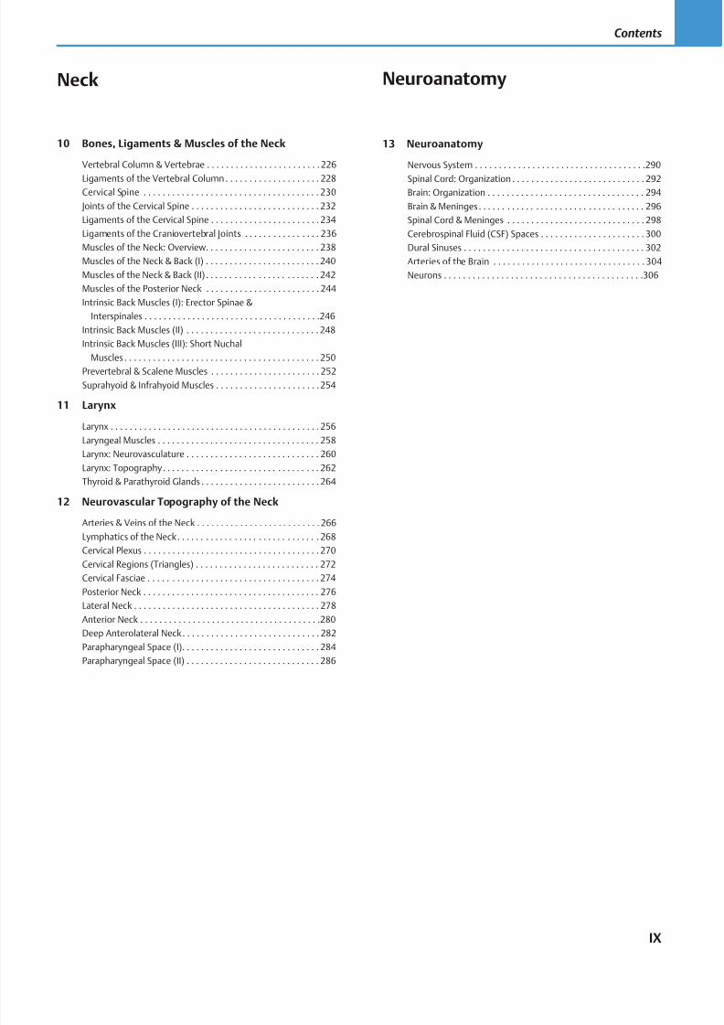
Neck
10 Bones, Ligaments & Muscles of the Neck
Vertebral Column & Vertebrae . . . . . . . . . . . . . . . . . . . . . . . .226
Ligaments of the Vertebral Column . . . . . . . . . . . . . . . . . . . . 228Cervical Spine . . . . . . . . . . . . . . . . . . . . . . . . . . . . . . . . . . . . . 230
Joints of the Cervical Spine . . . . . . . . . . . . . . . . . . . . . . . . . . . 232
Ligaments of the Cervical Spine . . . . . . . . . . . . . . . . . . . . . . . 234
Ligaments of the Craniovertebral Joints . . . . . . . . . . . . . . . . 236
Muscles of the Neck: Overview. . . . . . . . . . . . . . . . . . . . . . . . 238
Muscles of the Neck & Back (I) . . . . . . . . . . . . . . . . . . . . . . . . 240
Muscles of the Neck & Back (II) . . . . . . . . . . . . . . . . . . . . . . . . 242
Muscles of the Posterior Neck . . . . . . . . . . . . . . . . . . . . . . . . 244
Intrinsic Back Muscles (I): Erector Spinae &
Interspinales . . . . . . . . . . . . . . . . . . . . . . . . . . . . . . . . . . . . .246
Intrinsic Back Muscles (II) . . . . . . . . . . . . . . . . . . . . . . . . . . . . 248
Intrinsic Back Muscles (III): Short Nuchal
Muscles . . . . . . . . . . . . . . . . . . . . . . . . . . . . . . . . . . . . . . . . . 250Prevertebral & Scalene Muscles . . . . . . . . . . . . . . . . . . . . . . . 252
Suprahyoid & Infrahyoid Muscles . . . . . . . . . . . . . . . . . . . . . .254
11 Larynx
Larynx . . . . . . . . . . . . . . . . . . . . . . . . . . . . . . . . . . . . . . . . . . . .256
Laryngeal Muscles . . . . . . . . . . . . . . . . . . . . . . . . . . . . . . . . . . 258
Larynx: Neurovasculature . . . . . . . . . . . . . . . . . . . . . . . . . . . . 260
Larynx: Topography . . . . . . . . . . . . . . . . . . . . . . . . . . . . . . . . . 262
Thyroid & Parathyroid Glands . . . . . . . . . . . . . . . . . . . . . . . . . 264
12 Neurovascular Topography of the Neck
Arteries & Veins of the Neck . . . . . . . . . . . . . . . . . . . . . . . . . . 266
Lymphatics of the Neck . . . . . . . . . . . . . . . . . . . . . . . . . . . . . . 268Cervical Plexus . . . . . . . . . . . . . . . . . . . . . . . . . . . . . . . . . . . . . 270
Cervical Regions (Triangles) . . . . . . . . . . . . . . . . . . . . . . . . . . 272
Cervical Fasciae . . . . . . . . . . . . . . . . . . . . . . . . . . . . . . . . . . . . 274
Posterior Neck . . . . . . . . . . . . . . . . . . . . . . . . . . . . . . . . . . . . . 276
Lateral Neck . . . . . . . . . . . . . . . . . . . . . . . . . . . . . . . . . . . . . . . 278
Anterior Neck . . . . . . . . . . . . . . . . . . . . . . . . . . . . . . . . . . . . . .280
Deep Anterolateral Neck . . . . . . . . . . . . . . . . . . . . . . . . . . . . . 282
Parapharyngeal Space (I). . . . . . . . . . . . . . . . . . . . . . . . . . . . . 284
Parapharyngeal Space (II) . . . . . . . . . . . . . . . . . . . . . . . . . . . . 286
13 Neuroanatomy
Nervous System . . . . . . . . . . . . . . . . . . . . . . . . . . . . . . . . . . . .290
Spinal Cord: Organization . . . . . . . . . . . . . . . . . . . . . . . . . . . . 292Brain: Organization . . . . . . . . . . . . . . . . . . . . . . . . . . . . . . . . . 294
Brain & Meninges . . . . . . . . . . . . . . . . . . . . . . . . . . . . . . . . . . . 296
Spinal Cord & Meninges . . . . . . . . . . . . . . . . . . . . . . . . . . . . . 298
Cerebrospinal Fluid (CSF) Spaces . . . . . . . . . . . . . . . . . . . . . . 300
Dural Sinuses . . . . . . . . . . . . . . . . . . . . . . . . . . . . . . . . . . . . . . 302
Arteries of the Brain . . . . . . . . . . . . . . . . . . . . . . . . . . . . . . . . 304
Neurons . . . . . . . . . . . . . . . . . . . . . . . . . . . . . . . . . . . . . . . . . .306
IX
Contents
Neuroanatomy
8/15/2019 Head and Neck Anatomy for Dental Medicine - Thieme; (January 26, 2010)
http://slidepdf.com/reader/full/head-and-neck-anatomy-for-dental-medicine-thieme-january-26-2010 11/384
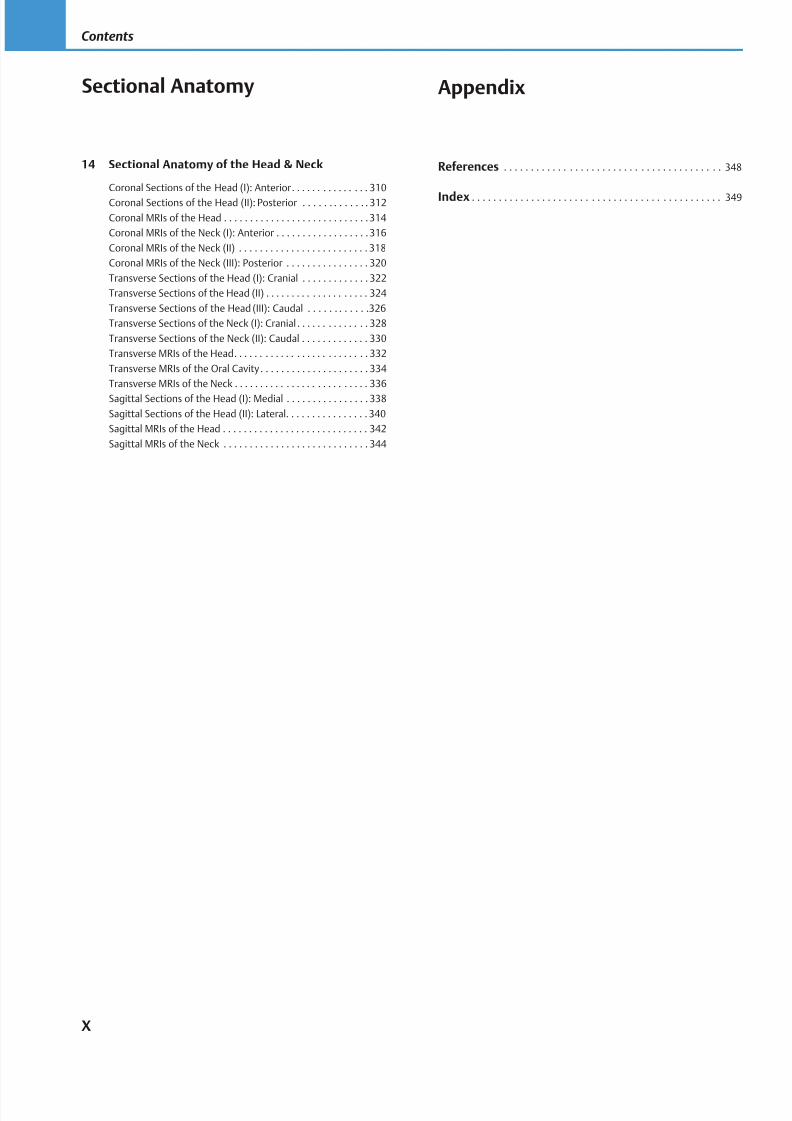
14 Sectional Anatomy of the Head & Neck
Coronal Sections of the Head (I): Anterior . . . . . . . . . . . . . . . 310
Coronal Sections of the Head (II): Posterior . . . . . . . . . . . . . 312
Coronal MRIs of the Head . . . . . . . . . . . . . . . . . . . . . . . . . . . .314
Coronal MRIs of the Neck (I): Anterior . . . . . . . . . . . . . . . . . .316
Coronal MRIs of the Neck (II) . . . . . . . . . . . . . . . . . . . . . . . . . 318
Coronal MRIs of the Neck (III): Posterior . . . . . . . . . . . . . . . . 320
Transverse Sections of the Head (I): Cranial . . . . . . . . . . . . . 322
Transverse Sections of the Head (II) . . . . . . . . . . . . . . . . . . . . 324
Transverse Sections of the Head (III): Caudal . . . . . . . . . . . .326
Transverse Sections of the Neck (I): Cranial . . . . . . . . . . . . . . 328
Transverse Sections of the Neck (II): Caudal . . . . . . . . . . . . . 330
Transverse MRIs of the Head . . . . . . . . . . . . . . . . . . . . . . . . . . 332
Transverse MRIs of the Oral Cavity . . . . . . . . . . . . . . . . . . . . . 334
Transverse MRIs of the Neck . . . . . . . . . . . . . . . . . . . . . . . . . . 336
Sagittal Sections of the Head (I): Medial . . . . . . . . . . . . . . . . 338
Sagittal Sections of the Head (II): Lateral. . . . . . . . . . . . . . . . 340
Sagittal MRIs of the Head . . . . . . . . . . . . . . . . . . . . . . . . . . . . 342
Sagittal MRIs of the Neck . . . . . . . . . . . . . . . . . . . . . . . . . . . . 344
Appendix
References . . . . . . . . . . . . . . . . . . . . . . . . . . . . . . . . . . . . . . . . 348
Index . . . . . . . . . . . . . . . . . . . . . . . . . . . . . . . . . . . . . . . . . . . . . . 349
X
Contents
Sectional Anatomy
8/15/2019 Head and Neck Anatomy for Dental Medicine - Thieme; (January 26, 2010)
http://slidepdf.com/reader/full/head-and-neck-anatomy-for-dental-medicine-thieme-january-26-2010 12/384
I was amazed and impressed with the extraordinary detail, accuracy, andbeauty of the material that was created for the three-volume THIEME Atlas of
Anatomy by authors Michael Schuenke, Erik Schulte, and Udo Schumacher
and artists Markus Voll and Karl Wesker. I felt that these atlases and their ped-
agogical concepts were a significant addition to anatomical education. I was
delighted to be invited to use this exceptional material as the cornerstone of
an eff ort to create an atlas that specifically focuses on the structures of the
head and neck as they are taught to students of dental medicine.
Starting from the extensive coverage of these structures distributed across
the three volumes of THIEME Atlas of Anatomy , I have organized, revised,
and added new material to create Head and Neck Anatomy for Dental Medi-
cine, a learning atlas for the first-year students of dental medicine taking a
gross anatomy course. Because of the exceptional quality artwork and ex-planatory information concerning the structures of the head and the neck,
it can also serve as a reference for practitioners of dental medicine and for
students and practitioners in the more general field of dentistry (dental
hygiene, dental assistants, etc.) and/or any field dealing primarily with the
head and neck (ENT, speech pathology, ophthalmology, etc.).
Some key features of this atlas are as follows:
Organized in a user-friendly format in which each two-page spread is
a self-contained guide to a specific topic.
Intuitively arranged to facilitate learning. Coverage of each region be-
gins by discussing the bones and joints and then adds the muscles,the vasculature, and the nerves. This information is then integrated in
the topographic neurovascular anatomy coverage that follows.
Features large, full-color, highly detailed artwork with clear and thor-
ough labeling and descriptive captions, plus numerous schematics to
elucidate concepts and tables to summarize key information for re-
view and reference.
Includes a full chapter devoted to sectional anatomy with radiographic
images to demonstrate anatomy as seen in the clinical setting.
The study of head and neck anatomy is challenging due to the intricacies
of the structures involved, but this atlas manages to convey detailed ana-tomical information in a way that is both thorough and effi cient, making
for a very eff ective study tool.
Preface
I would like to thank Susana Tejada, class of 2010, Boston UniversitySchool of Dental Medicine, and the group of dedicated anatomy instruc-
tors who provided feedback to Thieme as they were developing the con-
cept for this atlas: Dr. Norman F. Capra, Department of Neural and Pain
Sciences, University of Maryland Dental School, Baltimore, Maryland; Dr.
Bob Hutchins, Associate Professor, Department of Biomedical Sciences,
Baylor College of Dentistry, Dallas, Texas; Dr. Brian R. MacPherson, Pro-
fessor and Vice-Chair, Department of Anatomy and Neurobiology, Uni-
versity of Kentucky, Lexington, Kentucky; and Dr. Nicholas Peter Piesco,
Associate Professor, Department of Oral Medicine, University of Pitts-
burgh, Pittsburgh, Pennsylvania.
I would like to thank my colleagues at New York University who assisted
me in this endeavor: Professor Terry Harrison, Department of Anthropol-ogy, for fostering my interests in comparative anatomy and instilling an
appreciation for detail and accuracy in anatomical description; Dr. Rich-
ard Cotty for his keen eye in looking over the sectional anatomy in this at-
las; Dr. Phyllis Slott, Dr. Elena Cunningham, Dr. Avelin Malyango, and Dr.
Johanna Warshaw for assistance in all things anatomy related, including
countless discussions on all aspects of current anatomical education and
the need for a detailed head and neck anatomy atlas. Finally, I would like
to thank Dr. Inder Singh for mentoring me as an anatomist and serving
as an inspirational anatomy professor.
I would like to thank my colleagues at Thieme Publishers who so profes-
sionally facilitated this eff ort. I wish to thank Cathrin Weinstein, MD, Edi-
torial Director, Educational Products, for inviting me to create this atlas.I extend very special thanks and appreciation to Bridget Queenan, Devel-
opmental Editor, who edited and developed the manuscript with an out-
standing talent for visualization and intuitive flow of information. I am
also very grateful to her for catching many details along the way while al-
ways patiently responding to requests for artwork and labeling changes.
Thanks to Julie O’Meara, Developmental Editor, for joining the team in
the correction phase. She graciously reminded me of deadlines, while
always being available to work with me on proofs and to troubleshoot
problems. Finally, thanks to Elsie Starbecker, Associate Manager, Book
Production, who with great care and speed produced this atlas with its
over 900 illustrations. Their hard work has made Head and Neck Anatomy
for Dental Medicine a reality.
Eric W. Baker
New York, New York
XI
8/15/2019 Head and Neck Anatomy for Dental Medicine - Thieme; (January 26, 2010)
http://slidepdf.com/reader/full/head-and-neck-anatomy-for-dental-medicine-thieme-january-26-2010 13/384
8/15/2019 Head and Neck Anatomy for Dental Medicine - Thieme; (January 26, 2010)
http://slidepdf.com/reader/full/head-and-neck-anatomy-for-dental-medicine-thieme-january-26-2010 14/384
Head
4 Innervation of the Head & Neck
Organization of the Nervous System . . . . . . . . . . . . . . . . . . . . 54
Sensory Pathways . . . . . . . . . . . . . . . . . . . . . . . . . . . . . . . . . . . 56
Motor Pathways . . . . . . . . . . . . . . . . . . . . . . . . . . . . . . . . . . . . . 58
Skeletal Muscle: Innervation & Embryonic Development . . . . 60
Autonomic Motor Pathways . . . . . . . . . . . . . . . . . . . . . . . . . . .62
Peripheral Nerves & Nerve Lesions . . . . . . . . . . . . . . . . . . . . . . 64
Cranial Nerves: Overview . . . . . . . . . . . . . . . . . . . . . . . . . . . . . 66
Cranial Nerve Nuclei . . . . . . . . . . . . . . . . . . . . . . . . . . . . . . . . . 68CN I & II: Olfactory & Optic Nerves . . . . . . . . . . . . . . . . . . . . . .70
CN III, IV & VI: Oculomotor, Trochlear &
Abducent Nerves . . . . . . . . . . . . . . . . . . . . . . . . . . . . . . . . . . 72
CN V: Trigeminal Nerve, Nuclei & Divisions . . . . . . . . . . . . . . . 74
CN V1: Trigeminal Nerve, Ophthalmic Division . . . . . . . . . . . .76
CN V2: Trigeminal Nerve, Maxillary Division . . . . . . . . . . . . . . 78
CN V3: Trigeminal Nerve, Mandibular Division . . . . . . . . . . . .80
CN VII: Facial Nerve, Nuclei & Internal
Branches . . . . . . . . . . . . . . . . . . . . . . . . . . . . . . . . . . . . . . . . .82
CN VII: Facial Nerve, External Branches &
Ganglia . . . . . . . . . . . . . . . . . . . . . . . . . . . . . . . . . . . . . . . . . . 84
CN VIII: Vestibulocochlear Nerve . . . . . . . . . . . . . . . . . . . . . . . 86
CN IX: Glossopharyngeal Nerve . . . . . . . . . . . . . . . . . . . . . . . . 88CN X: Vagus Nerve . . . . . . . . . . . . . . . . . . . . . . . . . . . . . . . . . . . 90
CN XI & XII: Accessory Spinal &
Hypoglossal Nerves . . . . . . . . . . . . . . . . . . . . . . . . . . . . . . . . 92
Neurovascular Pathways through the Skull Base . . . . . . . . . . . 94
5 Neurovascular Topography of the Head
Anterior Face . . . . . . . . . . . . . . . . . . . . . . . . . . . . . . . . . . . . . . . 96
Lateral Head: Superficial Layer . . . . . . . . . . . . . . . . . . . . . . . . . 98
Lateral Head: Intermediate Layer . . . . . . . . . . . . . . . . . . . . . . 100
Infratemporal Fossa: Contents . . . . . . . . . . . . . . . . . . . . . . . . 102
Pterygopalatine Fossa . . . . . . . . . . . . . . . . . . . . . . . . . . . . . . . 104
1 Cranial Bones
Development of the Cranial Bones . . . . . . . . . . . . . . . . . . . . . . . 2
Skull: Lateral View . . . . . . . . . . . . . . . . . . . . . . . . . . . . . . . . . . . . 4
Skull: Anterior View . . . . . . . . . . . . . . . . . . . . . . . . . . . . . . . . . . . 6
Skull: Posterior View & Cranial Sutures . . . . . . . . . . . . . . . . . . . 8
Calvaria . . . . . . . . . . . . . . . . . . . . . . . . . . . . . . . . . . . . . . . . . . . . 10
Skull Base: External View . . . . . . . . . . . . . . . . . . . . . . . . . . . . . . 12
Skull Base: Internal View . . . . . . . . . . . . . . . . . . . . . . . . . . . . . . 14
Sphenoid Bone . . . . . . . . . . . . . . . . . . . . . . . . . . . . . . . . . . . . . . 16Temporal Bone . . . . . . . . . . . . . . . . . . . . . . . . . . . . . . . . . . . . . . 18
Occipital Bone & Ethmoid Bones . . . . . . . . . . . . . . . . . . . . . . . 20
Mandible & Hyoid Bone . . . . . . . . . . . . . . . . . . . . . . . . . . . . . . . 22
2 Muscles of the Skull & Face
Muscles of Facial Expression . . . . . . . . . . . . . . . . . . . . . . . . . . . 24
Muscles of Facial Expression: Calvaria,
Ear & Eye . . . . . . . . . . . . . . . . . . . . . . . . . . . . . . . . . . . . . . . . . 26
Muscles of Facial Expression: Mouth . . . . . . . . . . . . . . . . . . . . 28
Muscles of Mastication: Overview . . . . . . . . . . . . . . . . . . . . . . 30
Muscles of Mastication: Deep Muscles . . . . . . . . . . . . . . . . . . . 32
Temporomandibular Joint (TMJ): Biomechanics . . . . . . . . . . . 34
Temporomandibular Joint (TMJ) . . . . . . . . . . . . . . . . . . . . . . . . 36Muscles of the Head: Origins & Insertions . . . . . . . . . . . . . . . .38
3 Arteries & Veins of the Head & Neck
Arteries of the Head: Overview . . . . . . . . . . . . . . . . . . . . . . . . 40
External Carotid Artery: Anterior, Medial &
Posterior Branches . . . . . . . . . . . . . . . . . . . . . . . . . . . . . . . . .42
External Carotid Artery: Maxillary Artery . . . . . . . . . . . . . . . . . 44
External Carotid Artery: Terminal Branches . . . . . . . . . . . . . . . 46
Internal Carotid Artery . . . . . . . . . . . . . . . . . . . . . . . . . . . . . . . 48
Veins of the Head: Overview . . . . . . . . . . . . . . . . . . . . . . . . . . . 50
Veins of the Head: Deep Veins . . . . . . . . . . . . . . . . . . . . . . . . . 52
8/15/2019 Head and Neck Anatomy for Dental Medicine - Thieme; (January 26, 2010)
http://slidepdf.com/reader/full/head-and-neck-anatomy-for-dental-medicine-thieme-january-26-2010 15/384
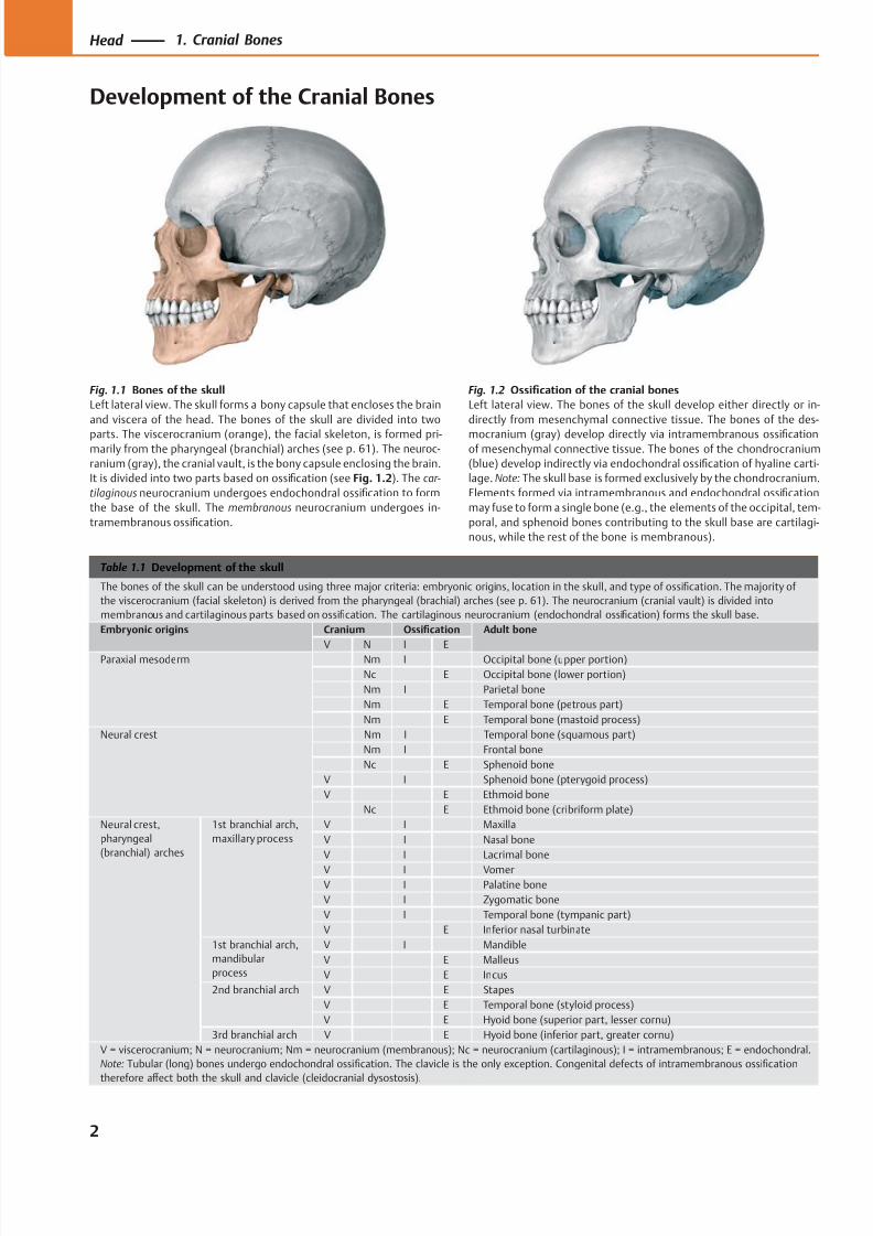
Table 1.1 Development of the skull
The bones of the skull can be understood using three major criteria: embryonic origins, location in the skull, and type of ossification. The majority of
the viscerocranium (facial skeleton) is derived from the pharyngeal (brachial) arches (see p. 61). The neurocranium (cranial vault) is divided into
membranous and cartilaginous parts based on ossification. The cartilaginous neurocranium (endochondral ossification) forms the skull base.
Embryonic origins Cranium Ossification Adult bone
V N I EParaxial mesoderm Nm I Occipital bone (upper portion)
Nc E Occipital bone (lower portion)
Nm I Parietal bone
Nm E Temporal bone (petrous part)
Nm E Temporal bone (mastoid process)
Neural crest Nm I Temporal bone (squamous part)
Nm I Frontal bone
Nc E Sphenoid bone
V I Sphenoid bone (pterygoid process)
V E Ethmoid bone
Nc E Ethmoid bone (cribriform plate)
Neural crest,
pharyngeal
(branchial) arches
1st branchial arch,
maxillary process
V I Maxilla
V I Nasal bone
V I Lacrimal bone
V I Vomer
V I Palatine bone
V I Zygomatic bone
V I Temporal bone (tympanic part)
V E Inferior nasal turbinate
1st branchial arch,
mandibular
process
V I Mandible
V E Malleus
V E Incus
2nd branchial arch V E Stapes
V E Temporal bone (styloid process)
V E Hyoid bone (superior part, lesser cornu)
3rd branchial arch V E Hyoid bone (inferior part, greater cornu)
V = viscerocranium; N = neurocranium; Nm = neurocranium (membranous); Nc = neurocranium (cartilaginous); I = intramembranous; E = endochondral.
Note: Tubular (long) bones undergo endochondral ossification. The clavicle is the only exception. Congenital defects of intramembranous ossification
therefore aff
ect both the skull and clavicle (cleidocranial dysostosis).
Fig. 1.2 Ossification of the cranial bones
Left lateral view. The bones of the skull develop either directly or in-
directly from mesenchymal connective tissue. The bones of the des-
mocranium (gray) develop directly via intramembranous ossificationof mesenchymal connective tissue. The bones of the chondrocranium
(blue) develop indirectly via endochondral ossification of hyaline carti-
lage. Note: The skull base is formed exclusively by the chondrocranium.
Elements formed via intramembranous and endochondral ossification
may fuse to form a single bone (e.g., the elements of the occipital, tem-
poral, and sphenoid bones contributing to the skull base are cartilagi-
nous, while the rest of the bone is membranous).
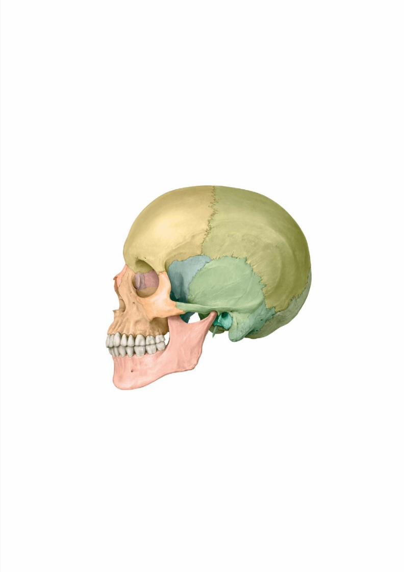
Fig. 1.1 Bones of the skull
Left lateral view. The skull forms a bony capsule that encloses the brain
and viscera of the head. The bones of the skull are divided into two
parts. The viscerocranium (orange), the facial skeleton, is formed pri-marily from the pharyngeal (branchial) arches (see p. 61). The neuroc-
ranium (gray), the cranial vault, is the bony capsule enclosing the brain.
It is divided into two parts based on ossification (see Fig. 1.2). The car-
tilaginous neurocranium undergoes endochondral ossification to form
the base of the skull. The membranous neurocranium undergoes in-
tramembranous ossification.
2
Head 1. Cranial Bones
Development of the Cranial Bones
8/15/2019 Head and Neck Anatomy for Dental Medicine - Thieme; (January 26, 2010)
http://slidepdf.com/reader/full/head-and-neck-anatomy-for-dental-medicine-thieme-january-26-2010 16/384
Sphenoid(anterolateral)
fontanelle
Mastoid (posterolateral)fontanelle
Lambdoidsuture
Posteriorfontanelle
Anterior fontanelle
A
Coronal
suture
Pterion
Squamoussuture
Lambdoidsuture
Asterion
Sphenofrontalsuture
Sphenosquamoussuture
Coronal suture
A
Frontal suture
Coronal suture
Anterior fontanelle
Posteriorfontanelle
Sagittalsuture
B
Bregma
Lambdoidsuture
Coronal suture
Lambda
Sagittal suture
B
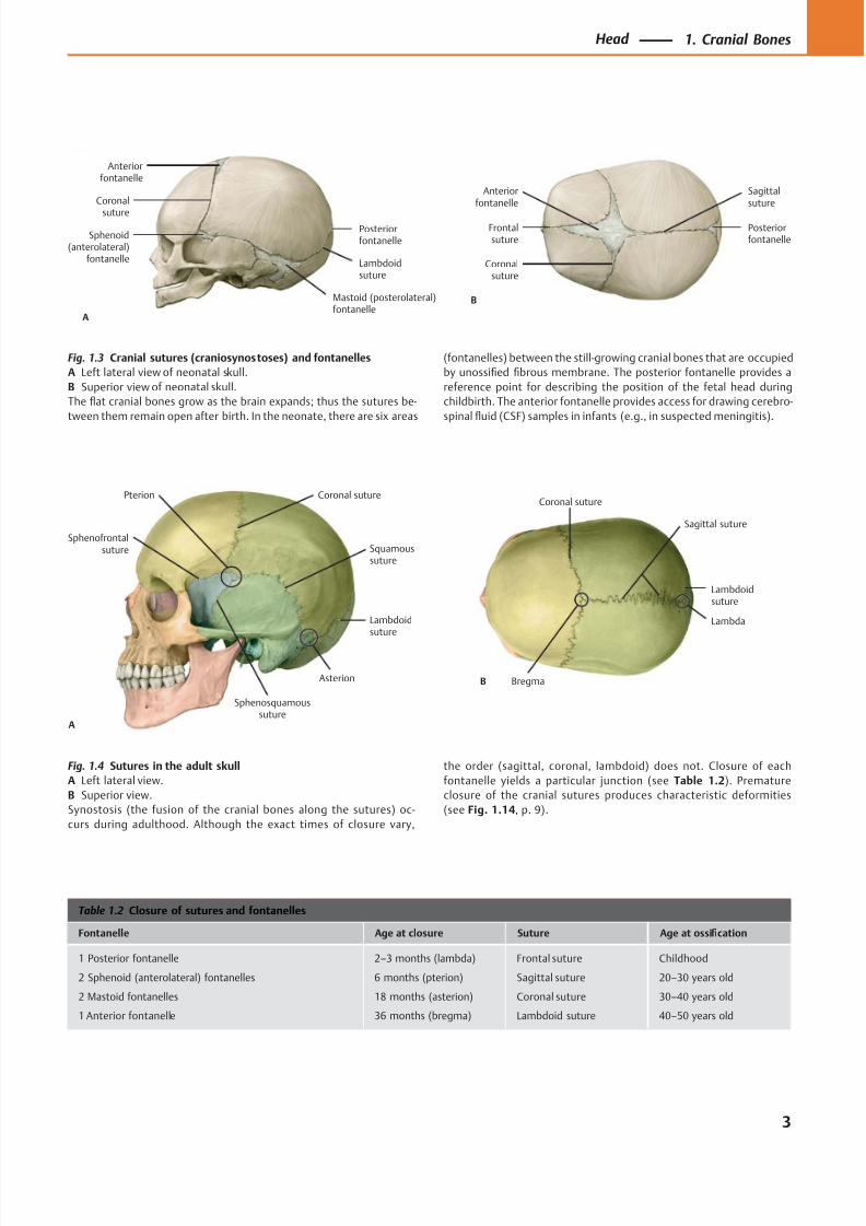
Fig. 1.3 Cranial sutures (craniosynostoses) and fontanelles
A Left lateral view of neonatal skull.
B Superior view of neonatal skull.
The flat cranial bones grow as the brain expands; thus the sutures be-
tween them remain open after birth. In the neonate, there are six areas
Fig. 1.4 Sutures in the adult skull
A Left lateral view.
B Superior view.
Synostosis (the fusion of the cranial bones along the sutures) oc-
curs during adulthood. Although the exact times of closure vary,
(fontanelles) between the still-growing cranial bones that are occupied
by unossified fibrous membrane. The posterior fontanelle provides a
reference point for describing the position of the fetal head during
childbirth. The anterior fontanelle provides access for drawing cerebro-
spinal fluid (CSF) samples in infants (e.g., in suspected meningitis).
the order (sagittal, coronal, lambdoid) does not. Closure of each
fontanelle yields a particular junction (see Table 1.2). Premature
closure of the cranial sutures produces characteristic deformities
(see Fig. 1.14, p. 9).
Table 1.2 Closure of sutures and fontanelles
Fontanelle Age at closure Suture Age at ossification
1 Posterior fontanelle
2 Sphenoid (anterolateral) fontanelles
2 Mastoid fontanelles
1 Anterior fontanelle
2–3 months (lambda)
6 months (pterion)
18 months (asterion)
36 months (bregma)
Frontal suture
Sagittal suture
Coronal suture
Lambdoid suture
Childhood
20–30 years old
30–40 years old
40–50 years old
3
Head 1. Cranial Bones
8/15/2019 Head and Neck Anatomy for Dental Medicine - Thieme; (January 26, 2010)
http://slidepdf.com/reader/full/head-and-neck-anatomy-for-dental-medicine-thieme-january-26-2010 17/384
Frontal bone
Coronal suture
Parietal bone
Lambdoidsuture
Mastoidforamen
Tympanomastoidfissure
Mastoidprocess
Postglenoidtubercle
Styloidprocess
Squamous suture
Zygomaticarch
Zygomatic bone
Mandible
Mental foramen
Maxilla
Infraorbitalforamen
Nasal bone
Lacrimal bone
Ethmoid bone
Sphenofrontalsuture
Sphenoid bone,greater wing
Supraorbitalforamen
Sphenoparietalsuture
Sphenosquamoussuture
Mentalprotuberance
Anteriornasal spine
Pterion
Asterion
Articulartubercle
External acousticmeatus
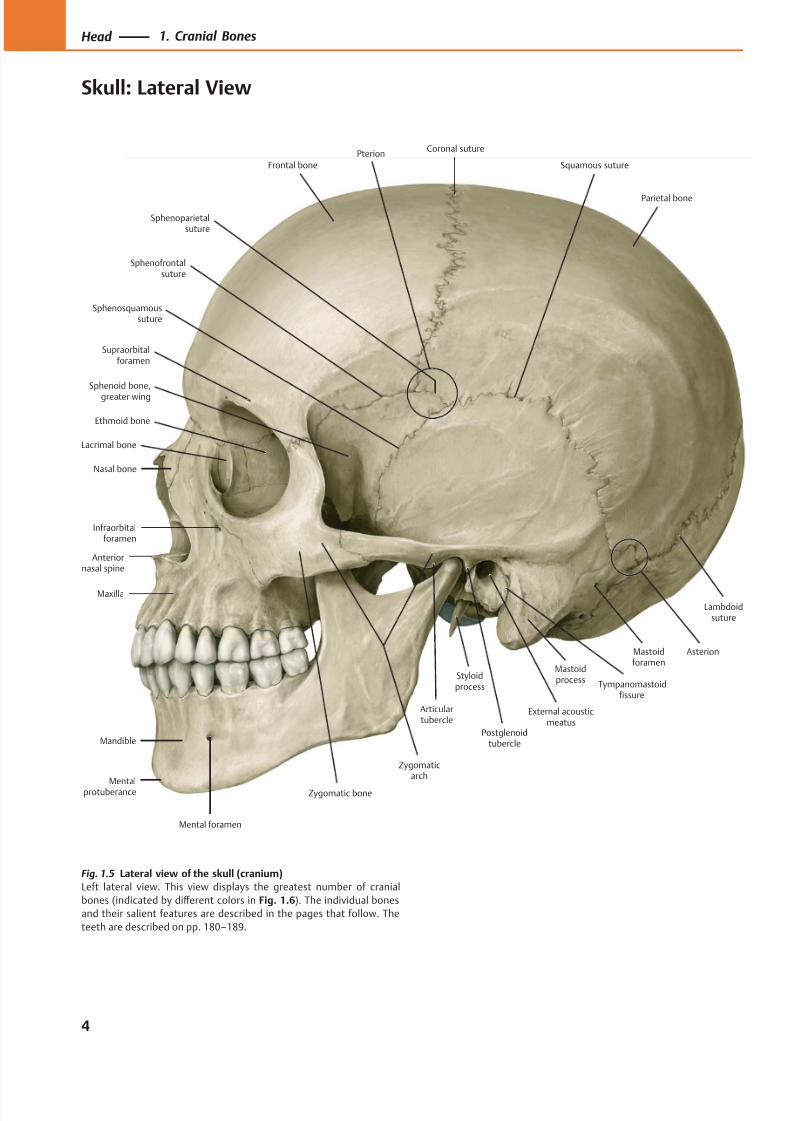
Fig. 1.5 Lateral view of the skull (cranium)
Left lateral view. This view displays the greatest number of cranial
bones (indicated by diff erent colors in Fig. 1.6). The individual bones
and their salient features are described in the pages that follow. The
teeth are described on pp. 180–189.
4
Head 1. Cranial Bones
Skull: Lateral View
8/15/2019 Head and Neck Anatomy for Dental Medicine - Thieme; (January 26, 2010)
http://slidepdf.com/reader/full/head-and-neck-anatomy-for-dental-medicine-thieme-january-26-2010 18/384
Frontal bone Parietal bone
Occipital bone
Temporal bone,petromastoid part
Zygomatic
bone
Maxilla
Nasal bone
Lacrimal bone
Ethmoid bone
Sphenoid bone,greater wing
Temporal bone,tympanic part
Temporal bone,squamous part
Mandible
Temporal bone,styloid process
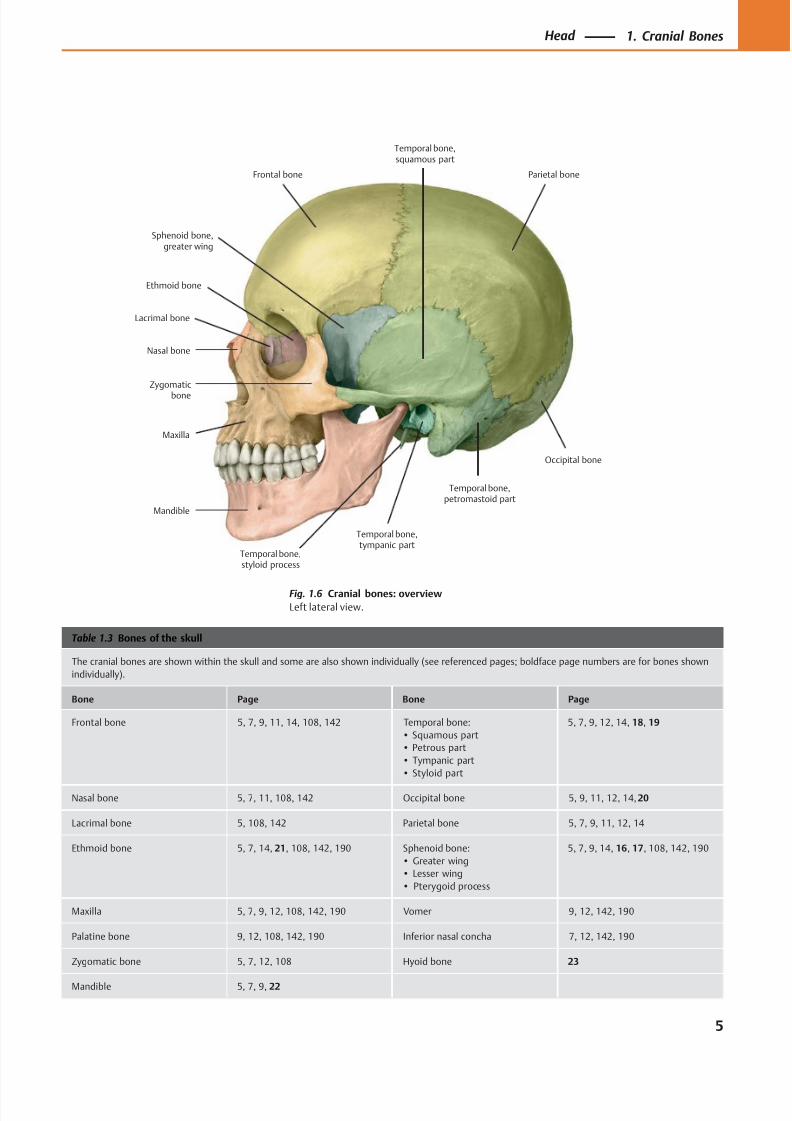
Table 1.3 Bones of the skull
The cranial bones are shown within the skull and some are also shown individually (see referenced pages; boldface page numbers are for bones shown
individually).
Bone Page Bone Page
Frontal bone 5, 7, 9, 11, 14, 108, 142 Temporal bone:
• Squamous part
• Petrous part
• Tympanic part
• Styloid part
5, 7, 9, 12, 14, 18, 19
Nasal bone 5, 7, 11, 108, 142 Occipital bone 5, 9, 11, 12, 14, 20
Lacrimal bone 5, 108, 142 Parietal bone 5, 7, 9, 11, 12, 14
Ethmoid bone 5, 7, 14, 21, 108, 142, 190 Sphenoid bone:
• Greater wing
• Lesser wing
• Pterygoid process
5, 7, 9, 14, 16, 17, 108, 142, 190
Maxilla 5, 7, 9, 12, 108, 142, 190 Vomer 9, 12, 142, 190
Palatine bone 9, 12, 108, 142, 190 Inferior nasal concha 7, 12, 142, 190
Zygomatic bone 5, 7, 12, 108 Hyoid bone 23
Mandible 5, 7, 9, 22
Fig. 1.6 Cranial bones: overview
Left lateral view.
5
Head 1. Cranial Bones
8/15/2019 Head and Neck Anatomy for Dental Medicine - Thieme; (January 26, 2010)
http://slidepdf.com/reader/full/head-and-neck-anatomy-for-dental-medicine-thieme-january-26-2010 19/384
SupraorbitalforamenSupraorbital
margin
Frontal incisure
Infraorbitalmargin
Ethmoid bone,middle nasal
concha
Sphenoid bone, lesser wing
Nasal bone
Piriform (anteriornasal) aperture
Anterior nasalspine
Mental foramenMandible
Infraorbital foramen
Maxilla
Sphenoid bone,greater wing
Zygomatic (malar)bone
Temporal bone
Sphenoid bone,greater wing
Parietal bone
Frontal bone
Inferior nasalconcha
Vomer
Ethmoid bone,perpendicular
plate
Teeth
Orbit
Intermaxillarysuture
Nasion
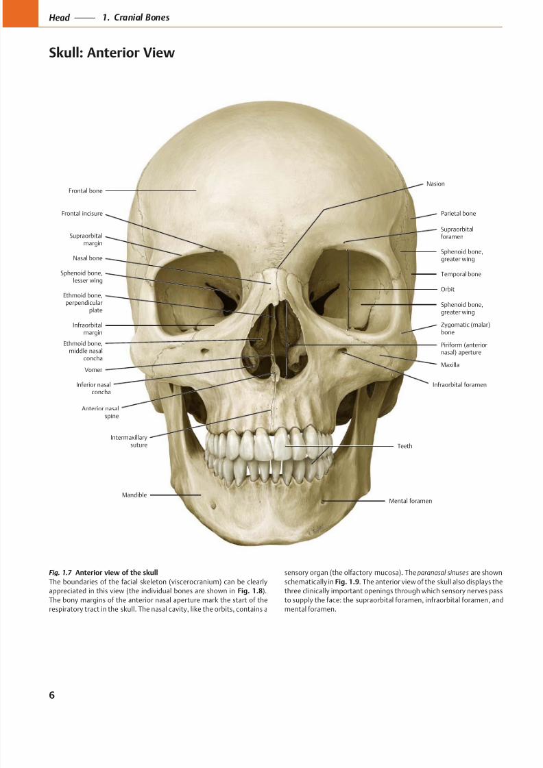
Fig. 1.7 Anterior view of the skull
The boundaries of the facial skeleton (viscerocranium) can be clearly
appreciated in this view (the individual bones are shown in Fig. 1.8).
The bony margins of the anterior nasal aperture mark the start of the
respiratory tract in the skull. The nasal cavity, like the orbits, contains a
sensory organ (the olfactory mucosa). The paranasal sinuses are shown
schematically in Fig. 1.9. The anterior view of the skull also displays the
three clinically important openings through which sensory nerves pass
to supply the face: the supraorbital foramen, infraorbital foramen, and
mental foramen.
6
Head 1. Cranial Bones
Skull: Anterior View
8/15/2019 Head and Neck Anatomy for Dental Medicine - Thieme; (January 26, 2010)
http://slidepdf.com/reader/full/head-and-neck-anatomy-for-dental-medicine-thieme-january-26-2010 20/384
Frontal bone
Parietal bone
Sphenoid bone,greater wing
Temporal bone
Zygomatic bone
Sphenoid bone,greater wing
Maxilla
Mandible
Nasal bone
Inferior nasal concha
Ethmoid bone,middle nasal
concha
Nasal cavity
Maxillary sinus
Sphenoid sinus
Ethmoid cells
Frontal sinus
Frontonasalpillar
Verticalzygomatic
pillar
Horizontalzygomatic pillar
A
Horizontalzygomatic pillar
Verticalzygomatic
pillar
Frontonasalpillar
B
I II III
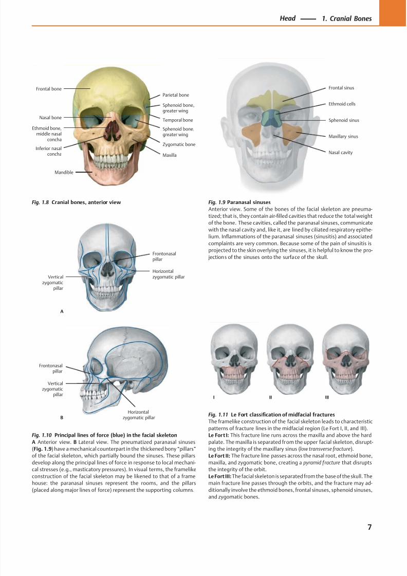
Fig. 1.8 Cranial bones, anterior view Fig. 1.9 Paranasal sinusesAnterior view. Some of the bones of the facial skeleton are pneuma-
tized; that is, they contain air-filled cavities that reduce the total weight
of the bone. These cavities, called the paranasal sinuses, communicate
with the nasal cavity and, like it, are lined by ciliated respiratory epithe-
lium. Inflammations of the paranasal sinuses (sinusitis) and associated
complaints are very common. Because some of the pain of sinusitis is
projected to the skin overlying the sinuses, it is helpful to know the pro-
jections of the sinuses onto the surface of the skull.
Fig. 1.10 Principal lines of force (blue) in the facial skeleton
A Anterior view. B Lateral view. The pneumatized paranasal sinuses
(Fig. 1.9) have a mechanical counterpart in the thickened bony “pillars”
of the facial skeleton, which partially bound the sinuses. These pillars
develop along the principal lines of force in response to local mechani-
cal stresses (e.g., masticatory pressures). In visual terms, the framelike
construction of the facial skeleton may be likened to that of a frame
house: the paranasal sinuses represent the rooms, and the pillars
(placed along major lines of force) represent the supporting columns.
Fig. 1.11 Le Fort classification of midfacial fractures
The framelike construction of the facial skeleton leads to characteristic
patterns of fracture lines in the midfacial region (Le Fort I, II, and III).
Le Fort I: This fracture line runs across the maxilla and above the hard
palate. The maxilla is separated from the upper facial skeleton, disrupt-
ing the integrity of the maxillary sinus (low transverse fracture).
Le Fort II: The fracture line passes across the nasal root, ethmoid bone,
maxilla, and zygomatic bone, creating a pyramid fracture that disrupts
the integrity of the orbit.
Le Fort III: The facial skeleton is separated from the base of the skull. The
main fracture line passes through the orbits, and the fracture may ad-
ditionally involve the ethmoid bones, frontal sinuses, sphenoid sinuses,
and zygomatic bones.
7
Head 1. Cranial Bones
8/15/2019 Head and Neck Anatomy for Dental Medicine - Thieme; (January 26, 2010)
http://slidepdf.com/reader/full/head-and-neck-anatomy-for-dental-medicine-thieme-january-26-2010 21/384
Supreme nuchal line
Superior nuchal line
Inferiornuchal line
Mandibular foramen
Incisiveforamen
Palatine bone
Maxilla, palatine process
Sphenoid bone,pterygoid process
Occipital condyle Temporal bone,styloid process
Mastoid foramina
Temporal bone,mastoid process
Lambdoidsuture
Parietal bone
Sagittal suture
Occipital plane
External occipitalprotuberance
Vomer
Temporal bone,petrous part
Temporal bone,squamous part
TeethMandible
Parietal foramina
Lambda
Mastoid notch
Mylohyoid groove
Mylohyoid line
Genial (mental) spinesDigastric fossa
Median nuchalline (external
occipital crest)
Asterion
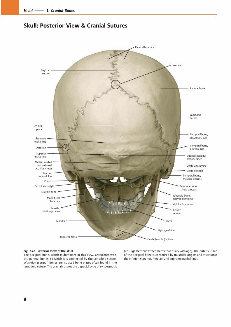
Fig. 1.12 Posterior view of the skull
The occipital bone, which is dominant in this view, articulates with
the parietal bones, to which it is connected by the lambdoid suture.
Wormian (sutural) bones are isolated bone plates often found in the
lambdoid suture. The cranial sutures are a special type of syndesmosis
(i.e., ligamentous attachments that ossify with age). The outer surface
of the occipital bone is contoured by muscular origins and insertions:
the inferior, superior, median, and supreme nuchal lines.
8
Head 1. Cranial Bones
Skull: Posterior View & Cranial Sutures
8/15/2019 Head and Neck Anatomy for Dental Medicine - Thieme; (January 26, 2010)
http://slidepdf.com/reader/full/head-and-neck-anatomy-for-dental-medicine-thieme-january-26-2010 22/384
B
Palatinebone
Mandible
Maxilla
Sphenoid bone
Temporal bone,petromastoid part
Temporal bone,squamous part
Parietal bone
Occipitalbone
Vomer
AA B C D
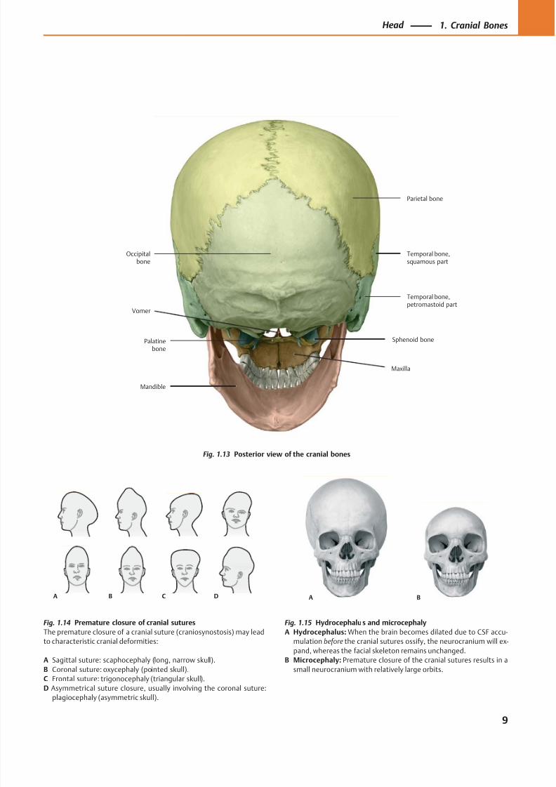
Fig. 1.13 Posterior view of the cranial bones
Fig. 1.14 Premature closure of cranial sutures
The premature closure of a cranial suture (craniosynostosis) may lead
to characteristic cranial deformities:
A Sagittal suture: scaphocephaly (long, narrow skull).
B Coronal suture: oxycephaly (pointed skull).
C Frontal suture: trigonocephaly (triangular skull).
D Asymmetrical suture closure, usually involving the coronal suture:plagiocephaly (asymmetric skull).
Fig. 1.15 Hydrocephalus and microcephaly
A Hydrocephalus: When the brain becomes dilated due to CSF accu-
mulation before the cranial sutures ossify, the neurocranium will ex-
pand, whereas the facial skeleton remains unchanged.
B Microcephaly: Premature closure of the cranial sutures results in a
small neurocranium with relatively large orbits.
9
Head 1. Cranial Bones
8/15/2019 Head and Neck Anatomy for Dental Medicine - Thieme; (January 26, 2010)
http://slidepdf.com/reader/full/head-and-neck-anatomy-for-dental-medicine-thieme-january-26-2010 23/384
Frontalcrest
Groove for
superior sagittalsinus
Meningealgrooves
Granularfoveolae
Groove forsuperior sagittal sinus
Parietalforamen
Frontalbone
Frontalsinus
B
Parietalbone
Parietal foramen LambdoidsutureOccipital bone
Parietal bone
Coronalsuture
A
Frontal bone
Sagittalsuture
Nasal bone
Bregma
Superiorand inferior
temporal lines
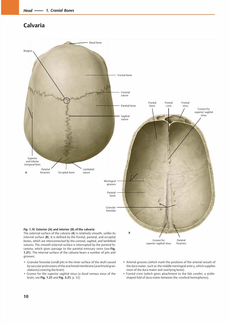
Fig. 1.16 Exterior (A) and interior (B) of the calvaria
The external surface of the calvaria (A) is relatively smooth, unlike its
internal surface (B). It is defined by the frontal, parietal, and occipital
bones, which are interconnected by the coronal, sagittal, and lambdoid
sutures. The smooth external surface is interrupted by the parietal fo-
ramina, which gives passage to the parietal emissary veins (see Fig.
1.21). The internal surface of the calvaria bears a number of pits and
grooves:
• Granular foveolae (small pits in the inner surface of the skull caused
by saccular protrusions of the arachnoid membrane [arachnoid gran-
ulations] covering the brain)
• Groove for the superior sagittal sinus (a dural venous sinus of the
brain, see Fig. 1.21 and Fig. 3.21, p. 53)
• Arterial grooves (which mark the positions of the arterial vessels of
the dura mater, such as the middle meningeal arter y, which supplies
most of the dura mater and overlying bone)
• Frontal crest (which gives attachment to the falx cerebri, a sickle-
shaped fold of dura mater between the cerebral hemispheres).
10
Head 1. Cranial Bones
Calvaria

8/15/2019 Head and Neck Anatomy for Dental Medicine - Thieme; (January 26, 2010)
http://slidepdf.com/reader/full/head-and-neck-anatomy-for-dental-medicine-thieme-january-26-2010 24/384
Emissary vein
Inner table
Diploë
Outer table
Scalp
Dural sinus
Diploic veins
Dura mater
Meningeal layerof dura mater
Falx cerebri
Endosteal layerof dura mater
Externalvertebral
venous plexus
Sigmoidsinus
Occipitalemissary veinand foramen
Condylaremissary vein
Mastoidemissary veinand foramen
Parietalemissary veinand foramen
Superior
sagittal sinus
Transversesinus
Confluence of the sinuses
Frontaldiploic
vein
Anteriortemporaldiploic vein
Occipitaldiploic vein
Posteriortemporaldiploic vein
Occipitalbone
Parietalbone
Frontalbone
Nasal bone
Fig. 1.21 Emissary veins of the occiput
Emissary veins establish a direct connection between the dural venous
sinuses and the extracranial veins. They pass through cranial openings
such as the parietal foramen and mastoid foramen. The emissary veins
are of clinical interest because they may allow bacteria from the scalp
to enter the skull along these veins and infect the dura mater, causing
meningitis.
Fig. 1.17 Exterior of the calvaria viewed from above Fig. 1.18 The scalp and calvaria
The three-layered calvaria consists of the outer table, the diploë, and
the inner table. The diploë has a spongy structure and contains red
(blood-forming) bone marrow. With a plasmacytoma (malignant trans-
formation of certain white blood cells), many small nests of tumorcells may destroy the surrounding bony trabeculae, and radiographs
will demonstrate multiple lucent areas (“punched-out lesions”) in the
skull.
Fig. 1.19 Sensitivity of the inner table to trauma
The inner table of the calvaria is very sensitive to external trauma and
may fracture even when the outer table remains intact (look for cor-
responding evidence on CT images).
Fig. 1.20 Diploic veins in the calvaria
The diploic veins are located in the cancellous or spongy tissue of the
cranial bones (the diploë) and are visible when the outer table is re-
moved. The diploic veins communicate with the dural venous sinuses
and scalp veins by way of the emissary veins, which create a potential
route for the spread of infection.
11
Head 1. Cranial Bones
8/15/2019 Head and Neck Anatomy for Dental Medicine - Thieme; (January 26, 2010)
http://slidepdf.com/reader/full/head-and-neck-anatomy-for-dental-medicine-thieme-january-26-2010 25/384
Inferior nasalconcha
Vomer
Parietal bone
Temporal bone,petrous part,mastoid part
Temporal bone,squamous part
Sphenoid bone
Frontal bone
Zygomatic bonePalatine bone
Palatineprocess
Occipital bone
Teeth
Temporal bone,tympanic part
Temporal bone,zygomatic process
Foramenmagnum
Zygomaticprocess
Maxilla
Medianpalatine suture
Transversepalatine suture
Lateral andmedial plates,
pterygoid process
Spheno-occipitalsynchrondrosis
Sphenoidsinus
Fibro-cartilage
Foramenlacerum
Carotidcanal
Middlecranial fossa
Cavernoussinus
Temporal bone,petrous part
Internal carotidartery
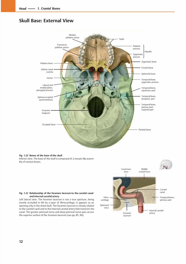
Fig. 1.22 Bones of the base of the skull
Inferior view. The base of the skull is composed of a mosaic-like assem-
bly of various bones.
Fig. 1.23 Relationship of the foramen lacerum to the carotid canal
and internal carotid artery
Left lateral view. The foramen lacerum is not a true aperture, being
mostly occluded in life by a layer of fibrocartilage; it appears as an
opening only in the dried skull. The foramen lacerum is closely related
to the carotid canal and to the internal carotid artery that traverses the
canal. The greater petrosal nerve and deep petrosal nerve pass across
the superior surface of the foramen lacerum (see pp. 85, 94).
12
Head 1. Cranial Bones
Skull Base: External View
8/15/2019 Head and Neck Anatomy for Dental Medicine - Thieme; (January 26, 2010)
http://slidepdf.com/reader/full/head-and-neck-anatomy-for-dental-medicine-thieme-january-26-2010 26/384
ChoanaPalatine bone
Greater palatineforamen
Lesser palatineforamen
Foramen ovale
Foramen lacerum
Foramen spinosum
Carotid canal
Jugular foramen
Stylomastoidforamen
Pharyngealtubercle
Hypoglossal(anterior condylar)
canal
Foramenmagnum
Inferiornuchal line
Superiornuchal line
Occipital condyle
Mastoidforamen
Mastoid process
Mandibular fossa
Hamulus
Zygomaticarch
Zygomatic bone,temporal surface
Inferior orbitalfissure
Incisiveforamen (canal)
Scaphoid fossa
Sphenoidalforamen
Infratemporalcrest
Median nuchal line
(Posterior)condylar canal
Mastoid incisure
Posterior nasalspine
Supremenuchal line
External occipital
protuberance
Pharyngeal canal
Vomerovaginalcanal
Petrotympanicfissure
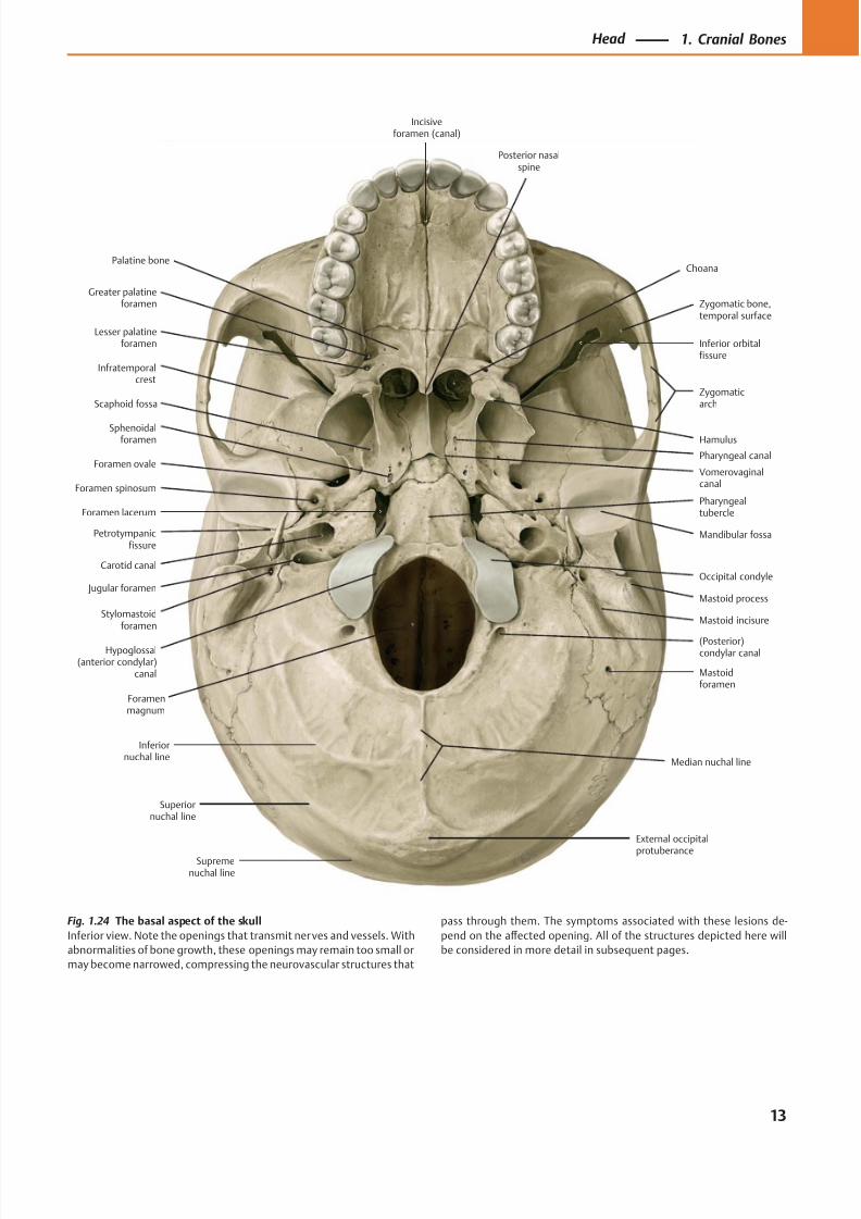
Fig. 1.24 The basal aspect of the skull
Inferior view. Note the openings that transmit nerves and vessels. With
abnormalities of bone growth, these openings may remain too small or
may become narrowed, compressing the neurovascular structures that
pass through them. The symptoms associated with these lesions de-
pend on the aff ected opening. All of the structures depicted here will
be considered in more detail in subsequent pages.
13
Head 1. Cranial Bones
8/15/2019 Head and Neck Anatomy for Dental Medicine - Thieme; (January 26, 2010)
http://slidepdf.com/reader/full/head-and-neck-anatomy-for-dental-medicine-thieme-january-26-2010 27/384
Dorsum sellae
Petrous ridge(crest)
Jugum sphenoidale
Posteriorcranial fossa
Middlecranial fossa
A
Anteriorcranial fossa
Sphenoid bone,lesser wing
Foramen magnum
Posteriorcranial fossa
Middlecranial fossa
Anteriorcranial fossa
BForamenmagnum
Occipital bone
Temporal bone,petromastoidpart
Temporal bone,squamous part
Sphenoid bone
Frontal bone Ethmoid bone
Parietal bone
Posteriortransversepillar
Anteriortransverse
pillar
Midlongitu-dinal pillar
Pterygoidpillar
Horizontal
zygomaticpillar
Verticalzygomaticpillar
Frontonasal pillar
A
B
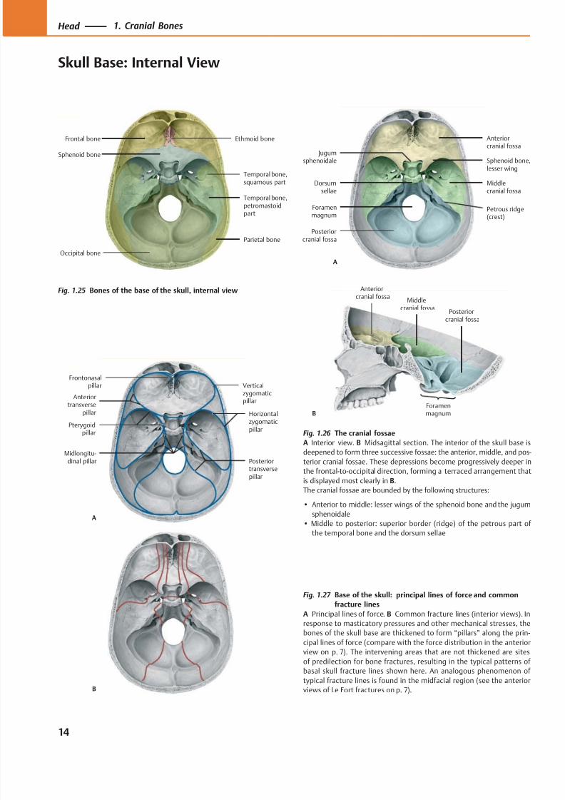
Fig. 1.25 Bones of the base of the skull, internal view
Fig. 1.27 Base of the skull: principal lines of force and common
fracture lines
A Principal lines of force. B Common fracture lines (interior views). In
response to masticatory pressures and other mechanical stresses, the
bones of the skull base are thickened to form “pillars” along the prin-
cipal lines of force (compare with the force distribution in the anterior
view on p. 7). The intervening areas that are not thickened are sites
of predilection for bone fractures, resulting in the typical patterns of
basal skull fracture lines shown here. An analogous phenomenon of
typical fracture lines is found in the midfacial region (see the anterior
views of Le Fort fractures on p. 7).
Fig. 1.26 The cranial fossae
A Interior view. B Midsagittal section. The interior of the skull base is
deepened to form three successive fossae: the anterior, middle, and pos-
terior cranial fossae. These depressions become progressively deeper in
the frontal-to-occipital direction, forming a terraced arrangement that
is displayed most clearly in B.
The cranial fossae are bounded by the following structures:
• Anterior to middle: lesser wings of the sphenoid bone and the jugum
sphenoidale
• Middle to posterior: superior border (ridge) of the petrous part of
the temporal bone and the dorsum sellae
14
Head 1. Cranial Bones
Skull Base: Internal View
8/15/2019 Head and Neck Anatomy for Dental Medicine - Thieme; (January 26, 2010)
http://slidepdf.com/reader/full/head-and-neck-anatomy-for-dental-medicine-thieme-january-26-2010 28/384
Optic canal
Anterior clinoidprocess
Foramen ovale
Foramenspinosum
Arterialgroove
Internalacoustic meatus
Foramen magnum
Cerebral fossa
Cerebellar fossa
Jugular foramen
Temporal bone,petrous part
Posterior clinoidprocess
Sphenoid bone,greater wing
Sphenoid bone,hypophyseal fossa
Sphenoid bone,lesser wing
Ethmoid bone,cribriform plate
Frontalsinus
Frontalcrest
Groove fortransverse
sinus
Groove forsigmoid
sinus
Hypoglossalcanal
Clivus
Foramenlacerum
Ethmoid bone,crista galli
Frontal bone
Petro-occipitalfissure
Internal occipitalprotuberance
Internaloccipital crest
Chiasmaticgroove
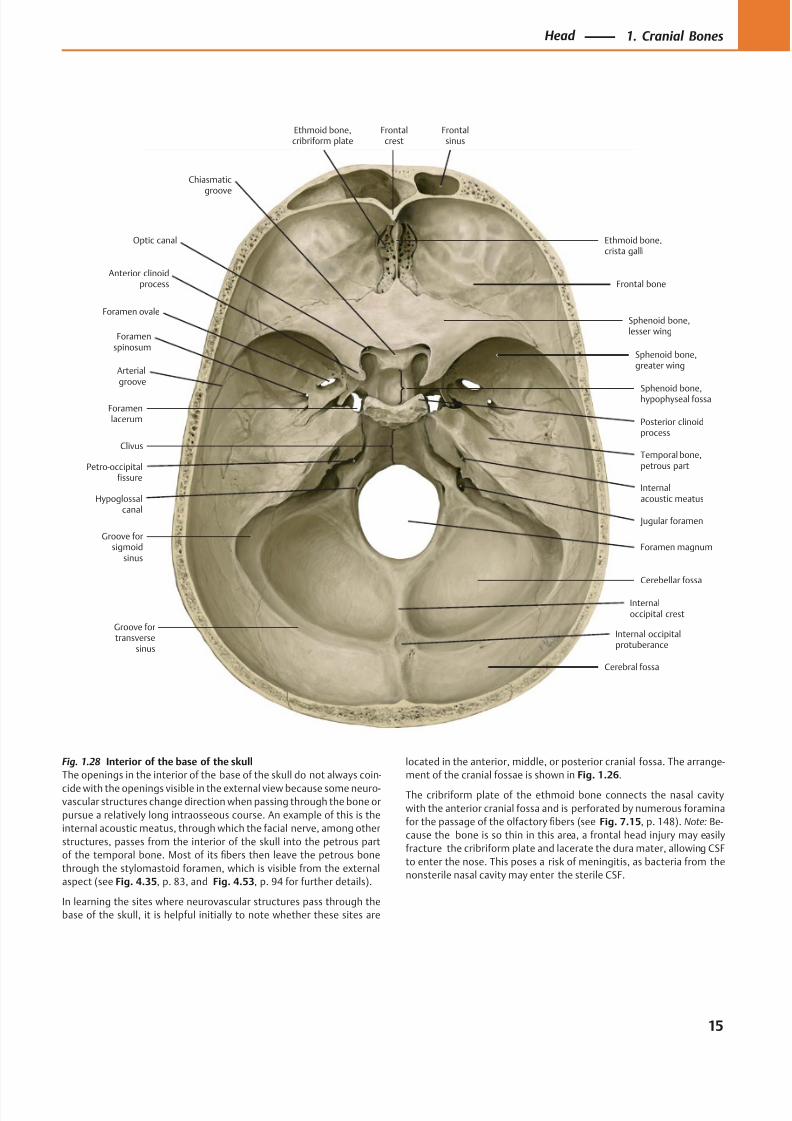
Fig. 1.28 Interior of the base of the skull
The openings in the interior of the base of the skull do not always coin-
cide with the openings visible in the external view because some neuro-vascular structures change direction when passing through the bone or
pursue a relatively long intraosseous course. An example of this is the
internal acoustic meatus, through which the facial nerve, among other
structures, passes from the interior of the skull into the petrous part
of the temporal bone. Most of its fibers then leave the petrous bone
through the stylomastoid foramen, which is visible from the external
aspect (see Fig. 4.35, p. 83, and Fig. 4.53, p. 94 for further details).
In learning the sites where neurovascular structures pass through the
base of the skull, it is helpful initially to note whether these sites are
located in the anterior, middle, or posterior cranial fossa. The arrange-
ment of the cranial fossae is shown in Fig. 1.26.
The cribriform plate of the ethmoid bone connects the nasal cavity
with the anterior cranial fossa and is perforated by numerous foramina
for the passage of the olfactory fibers (see Fig. 7.15, p. 148). Note: Be-
cause the bone is so thin in this area, a frontal head injury may easily
fracture the cribriform plate and lacerate the dura mater, allowing CSF
to enter the nose. This poses a risk of meningitis, as bacteria from the
nonsterile nasal cavity may enter the sterile CSF.
15
Head 1. Cranial Bones
8/15/2019 Head and Neck Anatomy for Dental Medicine - Thieme; (January 26, 2010)
http://slidepdf.com/reader/full/head-and-neck-anatomy-for-dental-medicine-thieme-january-26-2010 29/384
Occipitalbone
Temporalbone
Vomer
Palatine bone
A
Sphenoidbone
Parietalbone
Occipitalbone
Temporalbone
Frontalbone
B
Sphenoidbone
Temporalbone
Parietal bone
Frontal bone
C
Sphenoidbone,
greaterwing
Pterygoidprocess
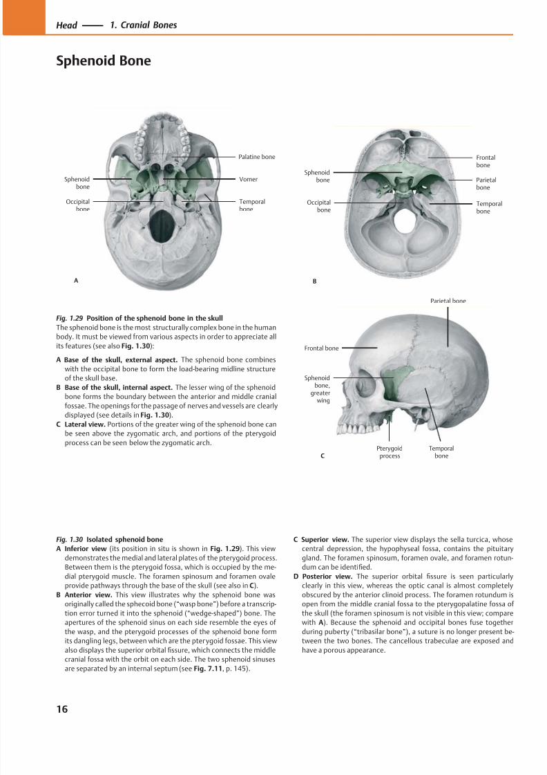
Fig. 1.29 Position of the sphenoid bone in the skull
The sphenoid bone is the most structurally complex bone in the human
body. It must be viewed from various aspects in order to appreciate all
its features (see also Fig. 1.30):
A Base of the skull, external aspect. The sphenoid bone combines
with the occipital bone to form the load-bearing midline structure
of the skull base.
B Base of the skull, internal aspect. The lesser wing of the sphenoid
bone forms the boundary between the anterior and middle cranial
fossae. The openings for the passage of nerves and vessels are clearlydisplayed (see details in Fig. 1.30).
C Lateral view. Portions of the greater wing of the sphenoid bone can
be seen above the zygomatic arch, and portions of the pterygoid
process can be seen below the zygomatic arch.
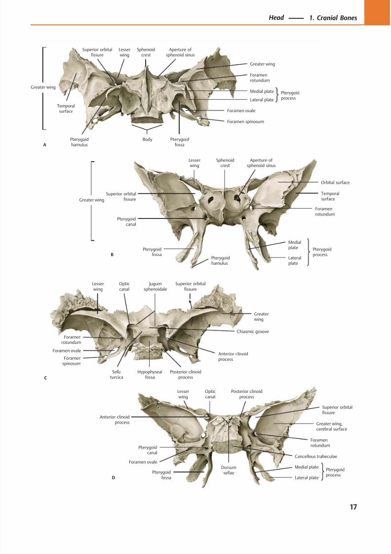
Fig. 1.30 Isolated sphenoid boneA Inferior view (its position in situ is shown in Fig. 1.29). This view
demonstrates the medial and lateral plates of the pterygoid process.
Between them is the pterygoid fossa, which is occupied by the me-
dial pterygoid muscle. The foramen spinosum and foramen ovale
provide pathways through the base of the skull (see also in C).
B Anterior view. This view illustrates why the sphenoid bone was
originally called the sphecoid bone (“wasp bone”) before a transcrip-
tion error turned it into the sphenoid (“wedge-shaped”) bone. The
apertures of the sphenoid sinus on each side resemble the eyes of
the wasp, and the pterygoid processes of the sphenoid bone form
its dangling legs, between which are the pterygoid fossae. This view
also displays the superior orbital fissure, which connects the middle
cranial fossa with the orbit on each side. The two sphenoid sinuses
are separated by an internal septum (see Fig. 7.11, p. 145).
C Superior view. The superior view displays the sella turcica, whosecentral depression, the hypophyseal fossa, contains the pituitary
gland. The foramen spinosum, foramen ovale, and foramen rotun-
dum can be identified.
D Posterior view. The superior orbital fissure is seen particularly
clearly in this view, whereas the optic canal is almost completely
obscured by the anterior clinoid process. The foramen rotundum is
open from the middle cranial fossa to the pterygopalatine fossa of
the skull (the foramen spinosum is not visible in this view; compare
with A). Because the sphenoid and occipital bones fuse together
during puberty (“tribasilar bone”), a suture is no longer present be-
tween the two bones. The cancellous trabeculae are exposed and
have a porous appearance.
16
Head 1. Cranial Bones
Sphenoid Bone
8/15/2019 Head and Neck Anatomy for Dental Medicine - Thieme; (January 26, 2010)
http://slidepdf.com/reader/full/head-and-neck-anatomy-for-dental-medicine-thieme-january-26-2010 30/384
B
Pterygoidcanal
Pterygoidprocess
Medialplate
Lateralplate
Foramenrotundum
Temporalsurface
Orbital surface
Superior orbitalfissure
Lesserwing
Aperture of sphenoid sinus
Sphenoidcrest
Pterygoidfossa
Pterygoidhamulus
Greater wing
Anterior clinoidprocess
Opticcanal
Pterygoidcanal
Foramenrotundum
Medial platePterygoid
fossa Lateral plate
Greater wing,cerebral surface
Superior orbitalfissure
Lesserwing
Posterior clinoidprocess
D
Dorsumsellae
Cancellous trabeculae
Pterygoidprocess
Foramen ovale
Aperture of sphenoid sinus
Sphenoidcrest
Lesserwing
Superior orbitalfissure
Foramenrotundum
Temporalsurface
Greater wing
Body Pterygoidfossa
Pterygoidhamulus
Foramen ovale
Foramen spinosum
Pterygoid
processLateral plate
Medial plate
Greater wing
A
Foramenspinosum
Foramen ovale
Sellaturcica
Posterior clinoidprocess
Hypophysealfossa
Anterior clinoidprocess
Foramenrotundum
Optic
canal
Jugum
sphenoidale
Lesser
wing
C
Superior orbital
fissure
Greaterwing
Chiasmic groove
17
Head 1. Cranial Bones
8/15/2019 Head and Neck Anatomy for Dental Medicine - Thieme; (January 26, 2010)
http://slidepdf.com/reader/full/head-and-neck-anatomy-for-dental-medicine-thieme-january-26-2010 31/384
Occipitalbone
Parietalbone
Sphenoid bone,greater wing
Zygomaticbone
Temporalbone
Tympanicpart
Petromastoidpart
Squamouspart
AStyloid process
Mandibularfossa
Styloidprocess
Tympanicpart
Petromastoidpart
Squamouspart
B
Petrous
pyramid
Tympanicmembrane
Pharyngotympanic(auditory) tube
Internalcarotid artery
Internal jugular vein
Mastoidair cells
Chordatympani
Mastoid process
Facialnerve
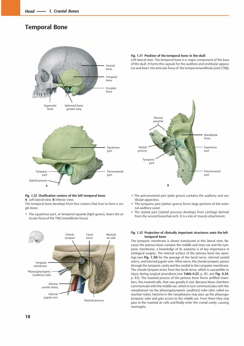
Fig. 1.31 Position of the temporal bone in the skull
Left lateral view. The temporal bone is a major component of the baseof the skull. It forms the capsule for the auditory and vestibular appara-
tus and bears the articular fossa of the temporomandibular joint (TMJ).
Fig. 1.32 Ossification centers of the left temporal bone
A Left lateral view. B Inferior view.
The temporal bone develops from four centers that fuse to form a sin-
gle bone:
• The squamous part, or temporal squama (light green), bears the ar-
ticular fossa of the TMJ (mandibular fossa).
• The petromastoid part (pale green) contains the auditory and ves-
tibular apparatus.
• The tympanic part (darker green) forms large portions of the exter-
nal auditory canal.
• The styloid part (styloid process) develops from cartilage derived
from the second branchial arch. It is a site of muscle attachment.
Fig. 1.33 Projection of clinically important structures onto the left
temporal bone
The tympanic membrane is shown translucent in this lateral view. Be-cause the petrous bone contains the middle and inner ear and the tym-
panic membrane, a knowledge of its anatomy is of key importance in
otological surgery. The internal surface of the petrous bone has open-
ings (see Fig. 1.34) for the passage of the facial nerve, internal carotid
artery, and internal jugular vein. Afine nerve, the chorda tympani, passes
through the tympanic cavity and lies medial to the tympanic membrane.
The chorda tympani arises from the facial nerve, which is susceptible to
injury during surgical procedures (see Table 4.22, p. 82, and Fig. 4.34,
p. 83). The mastoid process of the petrous bone forms air-filled cham-
bers, the mastoid cells, that vary greatly in size. Because these chambers
communicate with the middle ear, which in turn communicates with the
nasopharynx via the pharyngotympanic (auditory) tube (also called eu-
stachian tube), bacteria in the nasopharynx may pass up the pharyngo-
tympanic tube and gain access to the middle ear. From there they may
pass to the mastoid air cells and finally enter the cranial cavity, causingmeningitis.
18
Head 1. Cranial Bones
Temporal Bone
8/15/2019 Head and Neck Anatomy for Dental Medicine - Thieme; (January 26, 2010)
http://slidepdf.com/reader/full/head-and-neck-anatomy-for-dental-medicine-thieme-january-26-2010 32/384
Petrousapex
Groove for middlemeningeal arteries
Internalacoustic meatus
Zygomaticprocess
Styloidprocess
Groove forsigmoid sinus
Mastoidforamen
C
Petrous ridge(groove for superior
petrosal sinus)
Arcuateeminence
Aqueduct of the vestibule
Carotidcanal
Jugular fossa
Mastoidforamen
Mastoidnotch
Mastoidprocess
Stylomastoidforamen
Externalacoustic opening
Styloidprocess
Mandibularfossa
Articulartubercle
Zygomaticprocess
B
Mastoid canaliculus
Tympanic
canaliculus
Occipitalgroove
Petrotympanicfissure
Styloidprocess
Externalacoustic meatus
Mastoidprocess
Mastoidforamen
Externalacoustic opening
Temporalsurface
Mandibularfossa
Zygomaticprocess
Articulartubercle
A
Tympanomastoid
fissure
Postglenoidtubercle
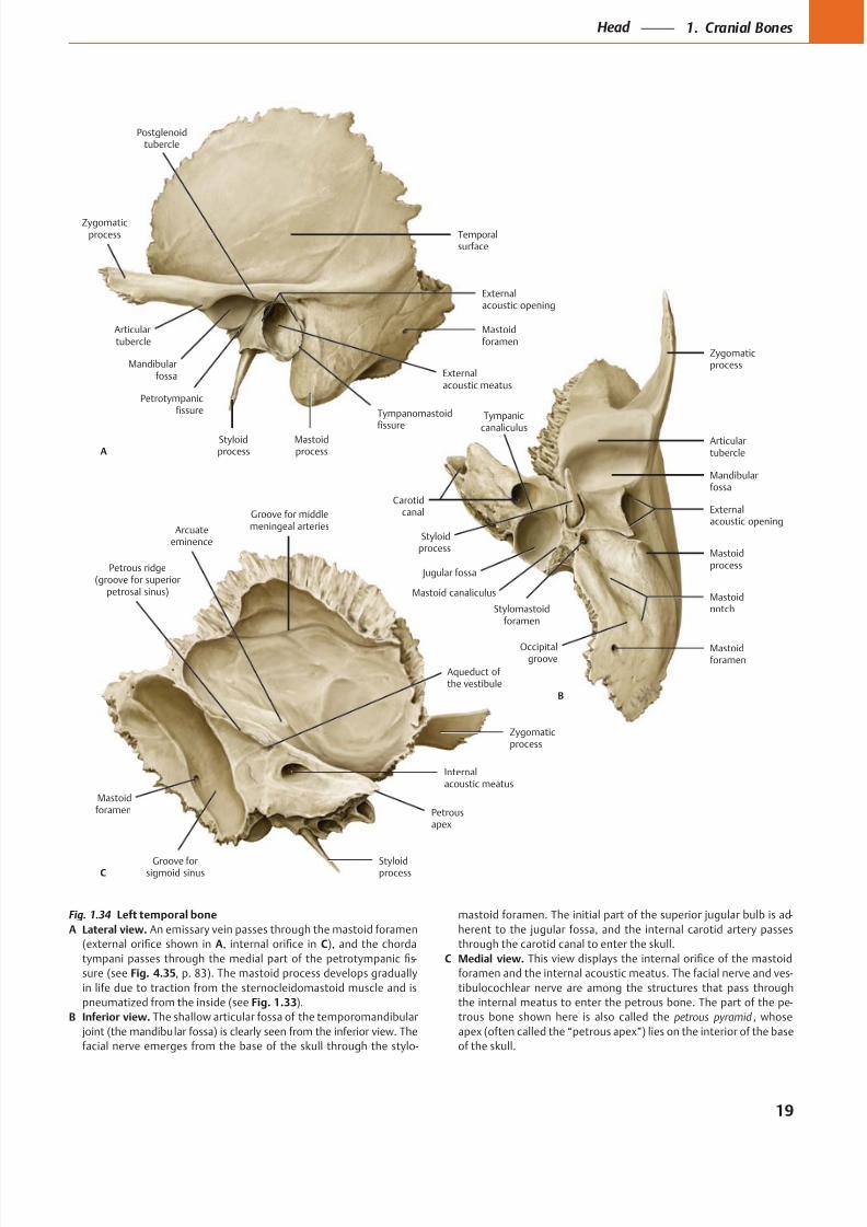
Fig. 1.34 Left temporal bone
A Lateral view. An emissary vein passes through the mastoid foramen
A C
-
sure (see Fig. 4.35
pneumatized from the inside (see Fig. 1.33).
B Inferior view.
-
C Medial view.
-
-
petrous pyramid
19
Head 1. Cranial Bones
8/15/2019 Head and Neck Anatomy for Dental Medicine - Thieme; (January 26, 2010)
http://slidepdf.com/reader/full/head-and-neck-anatomy-for-dental-medicine-thieme-january-26-2010 33/384
Pharyngealtubercle
Supremenuchal line
Superiornuchal line
External occipitalprotuberance
InferiornuchallineExternal
occipitalcrest
(mediannuchal line)
(Posterior)condylar
canal
Foramenmagnum
Hypoglossal (anteriorcondylar) canal
Basilar part
A
Occipitalcondyle
Hypoglossalcanal (anterior
condylar)
Jugular process
Posteriorcondylarcanal
B
Foramenmagnum
Occipitalsquama
Jugularnotch
Cruciformeminence
Foramenmagnum
Basilarpart
Posteriorcondylarcanal
Jugularprocess
Groove fortransversesinus
C
Groove forsuperiorsagittal sinus
Internaloccipitalprotuberance
Internaloccipitalcrest
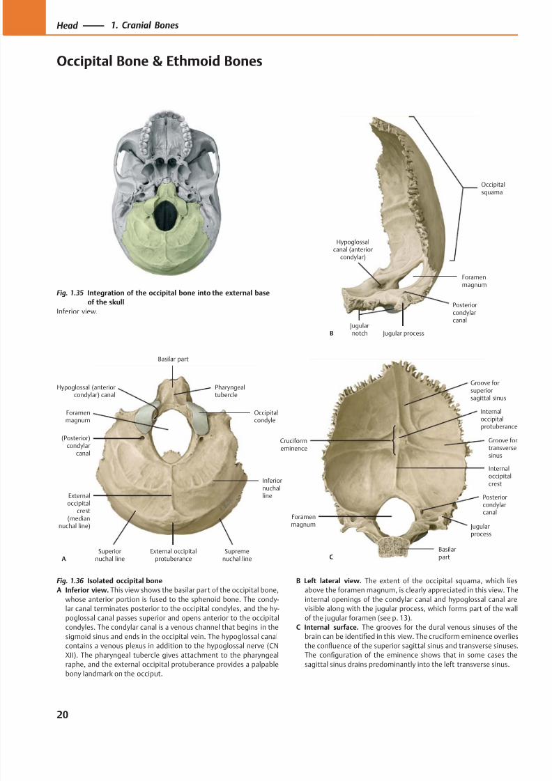
Fig. 1.35 Integration of the occipital bone into the external base
of the skull
Inferior view.
Fig. 1.36 Isolated occipital bone
A Inferior view. This view shows the basilar par t of the occipital bone,
whose anterior portion is fused to the sphenoid bone. The condy-
lar canal terminates posterior to the occipital condyles, and the hy-
poglossal canal passes superior and opens anterior to the occipital
condyles. The condylar canal is a venous channel that begins in the
sigmoid sinus and ends in the occipital vein. The hypoglossal canal
contains a venous plexus in addition to the hypoglossal nerve (CN
XII). The pharyngeal tubercle gives attachment to the pharyngeal
raphe, and the external occipital protuberance provides a palpable
bony landmark on the occiput.
B Left lateral view. The extent of the occipital squama, which lies
above the foramen magnum, is clearly appreciated in this view. The
internal openings of the condylar canal and hypoglossal canal are
visible along with the jugular process, which forms part of the wall
of the jugular foramen (see p. 13).
C Internal surface. The grooves for the dural venous sinuses of the
brain can be identified in this view. The cruciform eminence overlies
the confluence of the superior sagittal sinus and transverse sinuses.
The configuration of the eminence shows that in some cases the
sagittal sinus drains predominantly into the left transverse sinus.
20
Head 1. Cranial Bones
Occipital Bone & Ethmoid Bones
8/15/2019 Head and Neck Anatomy for Dental Medicine - Thieme; (January 26, 2010)
http://slidepdf.com/reader/full/head-and-neck-anatomy-for-dental-medicine-thieme-january-26-2010 34/384
Ethmoidair cells
Orbitalplate
Cribriformplate
Crista galli
Perpendicular
plate
A
Orbitalplate
Superiormeatus
Ethmoidair cells
Crista galli
BPerpendicularplate
Middleconcha
Ethmoidinfundibulum
Ethmoidbulla
Perpendicularplate
Middleconcha
Uncinateprocess
Crista galli
D
Superiorconcha
Crista galli
Perpen-dicular
plate Middleconcha
Posteriorethmoidforamen
Orbitalplate
Anterior
ethmoid foramen
Ethmoidair cells
C
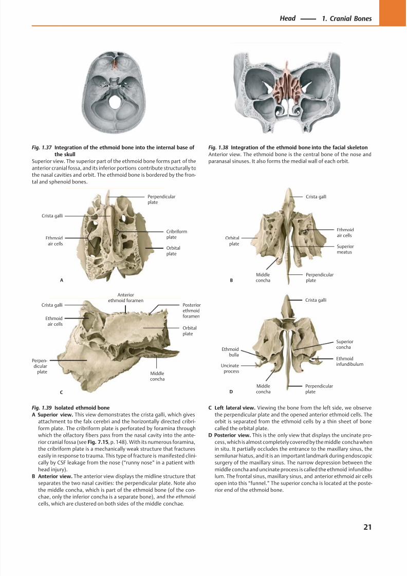
Fig. 1.37 Integration of the ethmoid bone into the internal base of
the skull
Superior view. The superior part of the ethmoid bone forms part of the
anterior cranial fossa, and its inferior portions contribute structurally to
the nasal cavities and orbit. The ethmoid bone is bordered by the fron-
tal and sphenoid bones.
Fig. 1.38 Integration of the ethmoid bone into the facial skeleton
Anterior view. The ethmoid bone is the central bone of the nose and
paranasal sinuses. It also forms the medial wall of each orbit.
Fig. 1.39 Isolated ethmoid bone
A Superior view. This view demonstrates the crista galli, which gives
attachment to the falx cerebri and the horizontally directed cribri-
form plate. The cribriform plate is perforated by foramina through
which the olfactory fibers pass from the nasal cavity into the ante-
rior cranial fossa (see Fig. 7.15, p. 148). With its numerous foramina,
the cribriform plate is a mechanically weak structure that fractures
easily in response to trauma. This type of fracture is manifested clini-
cally by CSF leakage from the nose (“runny nose” in a patient with
head injury).
B Anterior view. The anterior view displays the midline structure that
separates the two nasal cavities: the perpendicular plate. Note also
the middle concha, which is part of the ethmoid bone (of the con-
chae, only the inferior concha is a separate bone), and the ethmoid
cells, which are clustered on both sides of the middle conchae.
C Left lateral view. Viewing the bone from the left side, we observe
the perpendicular plate and the opened anterior ethmoid cells. The
orbit is separated from the ethmoid cells by a thin sheet of bone
called the orbital plate.
D Posterior view. This is the only view that displays the uncinate pro-
cess, which is almost completely covered by the middle concha when
in situ. It partially occludes the entrance to the maxillary sinus, the
semilunar hiatus, and it is an important landmark during endoscopic
surgery of the maxillary sinus. The narrow depression between the
middle concha and uncinate process is called the ethmoid infundibu-
lum. The frontal sinus, maxillary sinus, and anterior ethmoid air cells
open into this “funnel.” The superior concha is located at the poste-
rior end of the ethmoid bone.
21
Head 1. Cranial Bones
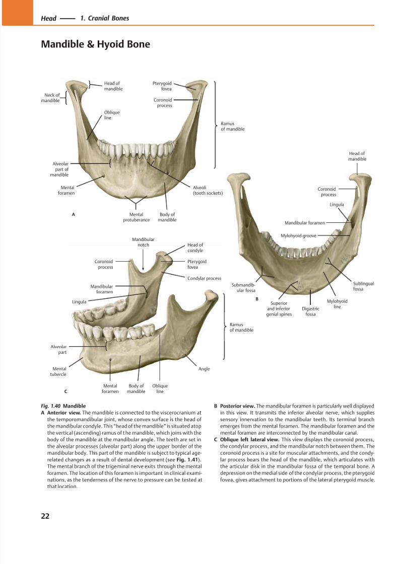
8/15/2019 Head and Neck Anatomy for Dental Medicine - Thieme; (January 26, 2010)
http://slidepdf.com/reader/full/head-and-neck-anatomy-for-dental-medicine-thieme-january-26-2010 35/384
Ramusof mandible
Obliqueline
Alveoli(tooth sockets)
Mentalprotuberance
Mentalforamen
Alveolarpart of
mandible
Coronoidprocess
Head of mandible
A
Pterygoidfovea
Body of mandible
Neck of mandible
Mylohyoidline
Mandibular foramen
Coronoidprocess
Head ofmandible
B
Lingula
Mylohyoid groove
Sublingualfossa
Digastricfossa
Superiorand inferiorgenial spines
Submandib-ular fossa
C
Angle
Obliqueline
Mentalforamen
Alveolarpart
Mentaltubercle
Mandibularforamen
Mandibularnotch
Coronoidprocess
Ramusof mandible
Pterygoidfovea
Head ofcondyle
Condylar process
Lingula
Body of mandible
Fig. 1.40 Mandible
A Anterior view. The mandible is connected to the viscerocranium at
the temporomandibular joint, whose convex surface is the head of
the mandibular condyle. This “head of the mandible” is situated atop
the vertical (ascending) ramus of the mandible, which joins with the
body of the mandible at the mandibular angle. The teeth are set in
the alveolar processes (alveolar part) along the upper border of the
mandibular body. This part of the mandible is subject to typical age-
related changes as a result of dental development (see Fig. 1.41).
The mental branch of the trigeminal nerve exits through the mental
foramen. The location of this foramen is important in clinical exami-
nations, as the tenderness of the nerve to pressure can be tested at
that location.
B Posterior view. The mandibular foramen is particularly well displayed
in this view. It transmits the inferior alveolar nerve, which supplies
sensory innervation to the mandibular teeth. Its terminal branch
emerges from the mental foramen. The mandibular foramen and the
mental foramen are interconnected by the mandibular canal.
C Oblique left lateral view. This view displays the coronoid process,
the condylar process, and the mandibular notch between them. The
coronoid process is a site for muscular attachments, and the condy-
lar process bears the head of the mandible, which articulates with
the articular disk in the mandibular fossa of the temporal bone. A
depression on the medial side of the condylar process, the pterygoid
fovea, gives attachment to portions of the lateral pterygoid muscle.
22
Head 1. Cranial Bones
Mandible & Hyoid Bone
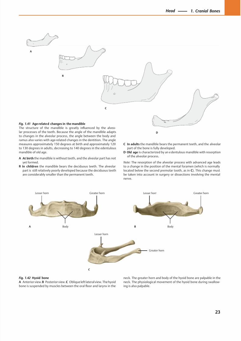
8/15/2019 Head and Neck Anatomy for Dental Medicine - Thieme; (January 26, 2010)
http://slidepdf.com/reader/full/head-and-neck-anatomy-for-dental-medicine-thieme-january-26-2010 36/384
B
C
D
A
Greater hornLesser horn
BodyA
Greater hornLesser horn
BodyB
Greater horn
Lesser horn
C
Fig. 1.41 Age-related changes in the mandible
The structure of the mandible is greatly influenced by the alveo-
lar processes of the teeth. Because the angle of the mandible adapts
to changes in the alveolar process, the angle between the body and
ramus also varies with age-related changes in the dentition. The angle
measures approximately 150 degrees at birth and approximately 120
to 130 degrees in adults, decreasing to 140 degrees in the edentulous
mandible of old age.
A At birth the mandible is without teeth, and the alveolar part has not
yet formed.
B In children the mandible bears the deciduous teeth. The alveolar
part is still relatively poorly developed because the deciduous teeth
are considerably smaller than the permanent teeth.
C In adults the mandible bears the permanent teeth, and the alveolar
part of the bone is fully developed.
D Old age is characterized by an edentulous mandible with resorption
of the alveolar process.
Note: The resorption of the alveolar process with advanced age leads
to a change in the position of the mental foramen (which is normally
located below the second premolar tooth, as in C). This change must
be taken into account in surgery or dissections involving the mental
nerve.
Fig. 1.42 Hyoid bone
A Anterior view.B Posterior view. C Oblique left lateral view. The hyoid
bone is suspended by muscles between the oral floor and larynx in the
neck. The greater horn and body of the hyoid bone are palpable in the
neck. The physiological movement of the hyoid bone during swallow-
ing is also palpable.
23
Head 1. Cranial Bones
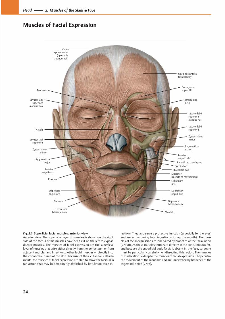
8/15/2019 Head and Neck Anatomy for Dental Medicine - Thieme; (January 26, 2010)
http://slidepdf.com/reader/full/head-and-neck-anatomy-for-dental-medicine-thieme-january-26-2010 37/384
Occipitofrontalis,frontal belly
Corrugatorsupercilii
Orbicularisoculi
Levator labiisuperiorisalaeque nasi
Levator labiisuperioris
Zygomaticusminor
Zygomaticusmajor
Levatoranguli oris
Buccinator
Masseter(muscle of mastication)
Orbicularisoris
Depressorlabii inferioris
Depressoranguli oris
MentalisDepressor
labii inferioris
Depressoranguli oris
Platysma
Risorius
Levatoranguli oris
Zygomaticusmajor
Zygomaticusminor
Levator labiisuperioris
Nasalis
Levator labiisuperioris
alaeque nasi
Procerus
Galeaaponeurotica
(epicranialaponeurosis)
Parotid duct and gland
Buccal fat pad
Fig. 2.1 Superficial facial muscles: anterior view
Anterior view. The superficial layer of muscles is shown on the right
side of the face. Certain muscles have been cut on the left to expose
deeper muscles. The muscles of facial expression are the superficial
layer of muscles that arise either directly from the periosteum or from
adjacent muscles and insert onto other facial muscles or directly into
the connective tissue of the skin. Because of their cutaneous attach-
ments, the muscles of facial expression are able to move the facial skin
(an action that may be temporarily abolished by botulinum toxin in-
jection). They also serve a protective function (especially for the eyes)
and are active during food ingestion (closing the mouth). The mus-
cles of facial expression are innervated by branches of the facial nerve
(CN VII). As these muscles terminate directly in the subcutaneous fat,
and because the superficial body fascia is absent in the face, surgeons
must be particularly careful when dissecting this region. The muscles
of mastication lie deep to the muscles of facial expression. They control
the movement of the mandible and are innervated by branches of the
trigeminal nerve (CN V).
24
Head 2. M uscles of the Skull & Face
Muscles of Facial Expression
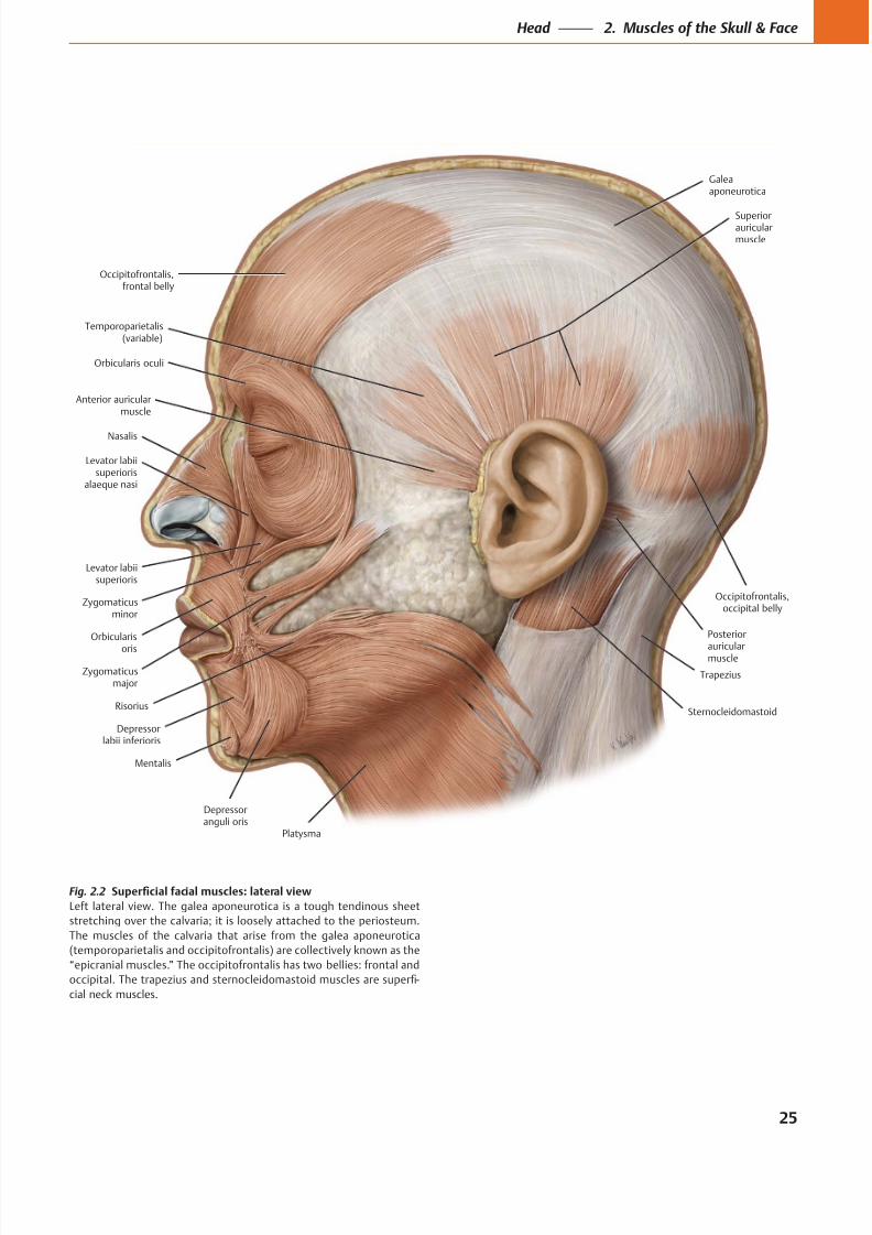
8/15/2019 Head and Neck Anatomy for Dental Medicine - Thieme; (January 26, 2010)
http://slidepdf.com/reader/full/head-and-neck-anatomy-for-dental-medicine-thieme-january-26-2010 38/384
Occipitofrontalis,frontal belly
Anterior auricularmuscle
Temporoparietalis(variable)
Galeaaponeurotica
Superiorauricularmuscle
Posterior
auricularmuscle
Occipitofrontalis,occipital belly
Platysma
Depressoranguli oris
Mentalis
Depressorlabii inferioris
Risorius
Zygomaticusmajor
Zygomaticusminor
Orbicularis
oris
Levator labiisuperioris
alaeque nasi
Levator labiisuperioris
Nasalis
Orbicularis oculi
Trapezius
Sternocleidomastoid
Fig. 2.2
Left lateral view. The galea aponeurotica is a tough tendinous sheet
stretching over the calvaria; it is loosely attached to the periosteum.
The muscles of the calvaria that arise from the galea aponeurotica
(temporoparietalis and occipitofrontalis) are collectively known as the
“epicranial muscles.” The occipitofrontalis has two bellies: frontal and
-
cial neck muscles.
25
Head 2. Muscles of the Skull & Face
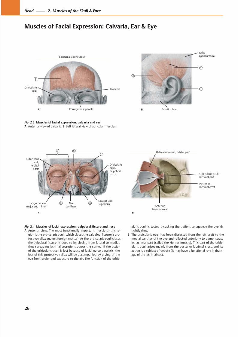
8/15/2019 Head and Neck Anatomy for Dental Medicine - Thieme; (January 26, 2010)
http://slidepdf.com/reader/full/head-and-neck-anatomy-for-dental-medicine-thieme-january-26-2010 39/384
①
A
Procerus
Corrugator supercilii
Epicranial aponeurosis
Orbicularisoculi
②
B
③
Parotid gland
Galeaaponeurotica
④
Orbicularis oculi,
lacrimal part
Posteriorlacrimal crest
Anteriorlacrimal crest
B
Orbicularis oculi, orbital part⑥
Orbicularisoculi,palpebralparts
Levator labiisuperioris
Orbicularisoculi,
orbitalparts
Alarcartilage
Zygomaticusmajor and minor
A
⑤⑦
⑧⑨
Fig. 2.3 Muscles of facial expression: calvaria and ear
A Anterior view of calvaria. B Left lateral view of auricular muscles.
Fig. 2.4 Muscles of facial expression: palpebral fissure and nose
A Anterior view. The most functionally important muscle of this re-
gion is the orbicularis oculi, which closes the palpebralfi
ssure (a pro-tective reflex against foreign matter). As the orbicularis oculi closes
the palpebral fissure, it does so by closing from lateral to medial,
thus spreading lacrimal secretions across the cornea. If the action
of the orbicularis oculi is lost because of facial nerve paralysis, the
loss of this protective reflex will be accompanied by drying of the
eye from prolonged exposure to the air. The function of the orbic-
ularis oculi is tested by asking the patient to squeeze the eyelids
tightly shut.
B The orbicularis oculi has been dissected from the left orbit to themedial canthus of the eye and reflected anteriorly to demonstrate
its lacrimal part (called the Horner muscle). This part of the orbic-
ularis oculi arises mainly from the posterior lacrimal crest, and its
action is a subject of debate (it may have a functional role in drain-
age of the lacrimal sac).
26
Head 2. M uscles of the Skull & Face
Muscles of Facial Expression: Calvaria, Ear & Eye
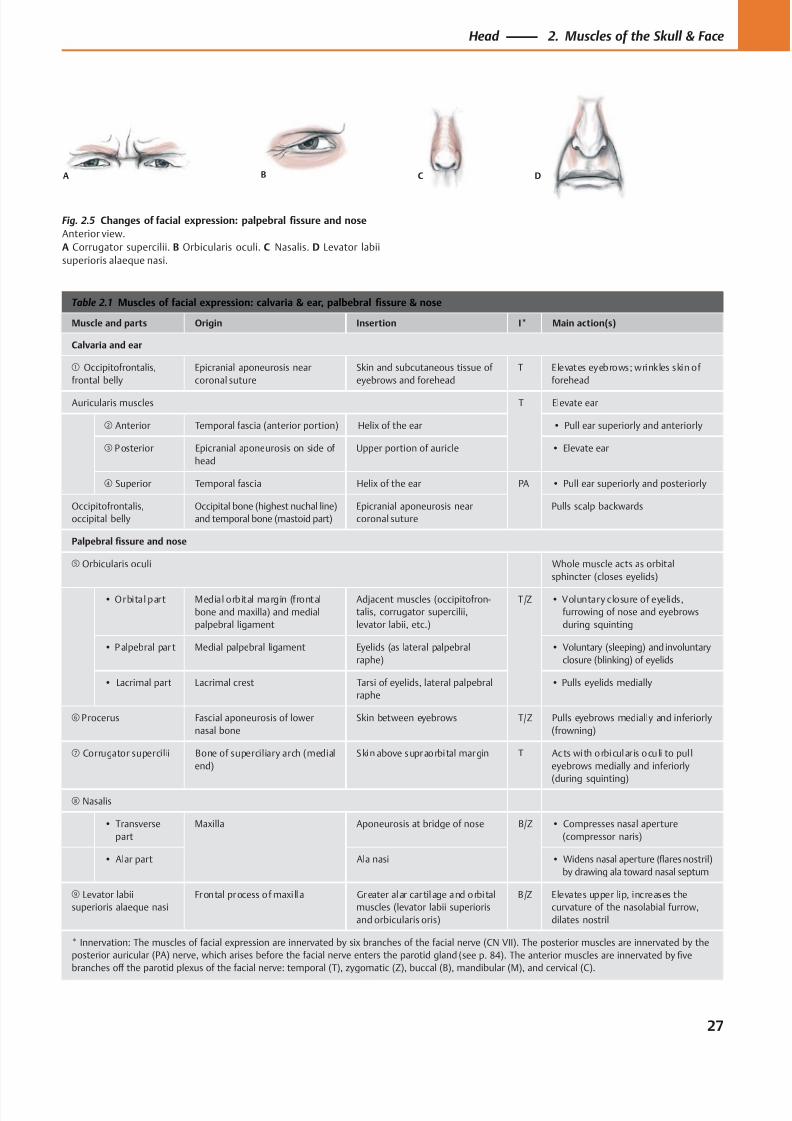
8/15/2019 Head and Neck Anatomy for Dental Medicine - Thieme; (January 26, 2010)
http://slidepdf.com/reader/full/head-and-neck-anatomy-for-dental-medicine-thieme-january-26-2010 40/384
A B C D
Table 2.1 Muscles of facial expression: calvaria & ear, palbebral fissure & nose
Muscle and parts Origin Insertion I* Main action(s)
Calvaria and ear
① Occipitofrontalis,
frontal belly
Epicranial aponeurosis near
coronal suture
Skin and subcutaneous tissue of
eyebrows and forehead
T Elevates eyebrows; wrinkles skin of
forehead
Auricularis muscles T Elevate ear
② Anterior Temporal fascia (anterior portion) Helix of the ear • Pull ear superiorly and anteriorly
③ P osterior Epicranial aponeurosis on side of
head
Upper portion of auricle • Elevate ear
④ Superior Temporal fascia Helix of the ear PA • Pull ear superiorly and posteriorly
Occipitofrontalis,
occipital belly
Occipital bone (highest nuchal line)
and temporal bone (mastoid part)
Epicranial aponeurosis near
coronal suture
Pulls scalp backwards
Palpebral fissure and nose
⑤ Orbicularis oculi Whole muscle acts as orbital
sphincter (closes eyelids)
• Orbital part Medial orbital margin (frontal
bone and maxilla) and medial
palpebral ligament
Adjacent muscles (occipitofron-
talis, corrugator supercilii,
levator labii, etc.)
T/Z • Voluntary closure of eyelids,
furrowing of nose and eyebrows
during squinting
• P alpebral par t Medial palpebral ligament Eyelids (as lateral palpebral
raphe)
• Voluntary (sleeping) and involuntary
closure (blinking) of eyelids
• Lacrimal part Lacrimal crest Tarsi of eyelids, lateral palpebral
raphe
• Pulls eyelids medially
⑥ Procerus Fascial aponeurosis of lower
nasal bone
Skin between eyebrows T/Z Pulls eyebrows medially and inferiorly
(frowning)
⑦ Corrugator supercilii Bone of superciliary arch (medial
end)
Skin above supraorbital margin T Acts with orbicular is oculi to pul l
eyebrows medially and inferiorly
(during squinting)
⑧ Nasalis
• Transverse
part
Maxilla Aponeurosis at bridge of nose B/Z • Compresses nasal aperture
(compressor naris)
• Alar part Ala nasi • Widens nasal aperture (flares nostril)
by drawing ala toward nasal septum
⑨ Levator labii
superioris alaeque nasi
Frontal process of maxi lla Greater alar cartilage and orbital
muscles (levator labii superioris
and orbicularis oris)
B/Z Elevates upper lip, increases the
curvature of the nasolabial furrow,
dilates nostril
* Innervation: The muscles of facial expression are innervated by six branches of the facial nerve (CN VII). The posterior muscles are innervated by the
posterior auricular (PA) nerve, which arises before the facial nerve enters the parotid gland (see p. 84). The anterior muscles are innervated by five
branches off the parotid plexus of the facial nerve: temporal (T), zygomatic (Z), buccal (B), mandibular (M), and cervical (C).
Fig. 2.5 Changes of facial expression: palpebral fissure and nose
Anterior view.
A Corrugator supercilii. B Orbicularis oculi. C Nasalis. D Levator labii
superioris alaeque nasi.
27
Head 2. Muscles of the Skull & Face
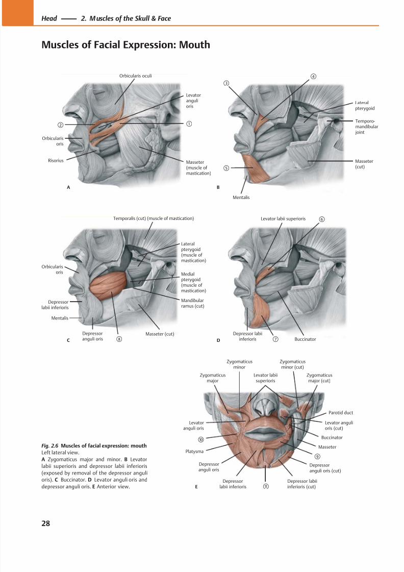
8/15/2019 Head and Neck Anatomy for Dental Medicine - Thieme; (January 26, 2010)
http://slidepdf.com/reader/full/head-and-neck-anatomy-for-dental-medicine-thieme-january-26-2010 41/384
Levator
angulioris
Orbicularisoris
Masseter(muscle of mastication)
①②
Orbicularis oculi
Risorius
A
Mentalis
Masseter(cut)
Lateralpterygoid
Temporo-mandibular joint
③
B
⑤
④
Orbicularisoris
Masseter (cut)
Depressorlabii inferioris
Depressoranguli oris
Medialpterygoid(muscle ofmastication)
Mentalis
C ⑧
Mandibularramus (cut)
Lateralpterygoid(muscle ofmastication)
Temporalis (cut) (muscle of mastication) Levator labii superioris ⑥
Buccinator⑦Depressor labii
inferiorisD
E
Levator labiisuperioris
Zygomaticusminor (cut)
Zygomaticusmajor (cut)
Levator angulioris (cut)
Buccinator
⑨
Depressor labiiinferioris (cut)
Depressoranguli oris (cut)
⑪
Depressoranguli oris
Platysma
⑩
Levatoranguli oris
Zygomaticusmajor
Zygomaticusminor
Depressorlabii inferioris
Parotid duct
MasseterFig. 2.6 Muscles of facial expression: mouth
Left lateral view.
A Zygomaticus major and minor. B Levator
labii superioris and depressor labii inferioris
(exposed by removal of the depressor anguli
oris). C Buccinator. D Levator anguli oris and
depressor anguli oris. E Anterior view.
28
Head 2. M uscles of the Skull & Face
Muscles of Facial Expression: Mouth
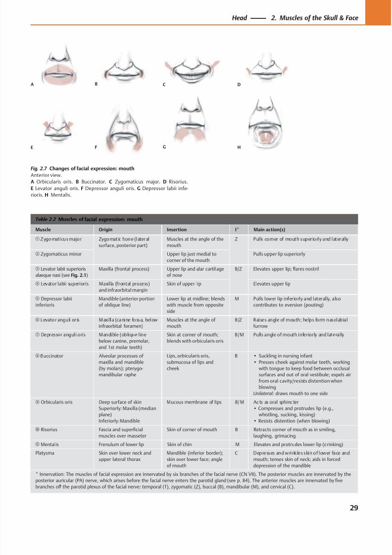
8/15/2019 Head and Neck Anatomy for Dental Medicine - Thieme; (January 26, 2010)
http://slidepdf.com/reader/full/head-and-neck-anatomy-for-dental-medicine-thieme-january-26-2010 42/384
A B C D
E F G H
Table 2.2 Muscles of facial expression: mouth
Muscle Origin Insertion I* Main action(s)
① Zygomaticus major Zygomatic bone (lateral
surface, posterior part)
Muscles at the angle of the
mouth
Z Pulls corner of mouth superiorly and laterally
② Zygomaticus minor Upper lip just medial to
corner of the mouth
Pulls upper lip superiorly
③ Levator labii superioris
alaeque nasi (see Fig. 2.1)
Maxilla (frontal process) Upper lip and alar cartilage
of nose
B/Z Elevates upper lip; flares nostril
④ Levator labii superioris Maxilla (frontal process)
and infraorbital margin
Skin of upper lip Elevates upper lip
⑤ Depressor labii
inferioris
Mandible (anterior portion
of oblique line)
Lower lip at midline; blends
with muscle from opposite
side
M Pulls lower lip inferiorly and laterally, also
contributes to eversion (pouting)
⑥ Levator anguli or is Maxi lla (canine fossa, below
infraorbital foramen)
Muscles at the angle of
mouth
B/Z Raises angle of mouth; helps form nasolabial
furrow
⑦ Depressor anguli oris Mandible (oblique line
below canine, premolar,
and 1st molar teeth)
Skin at corner of mouth;
blends with orbicularis oris
B/M Pulls angle of mouth inferiorly and laterally
⑧ Buccinator Alveolar processes of
maxilla and mandible
(by molars); pterygo-
mandibular raphe
Lips, orbicularis oris,
submucosa of lips and
cheek
B • Suckling in nursing infant
• Presses cheek against molar teeth, working
with tongue to keep food between occlusal
surfaces and out of oral vestibule; expels air
from oral cavity/resists distention when
blowingUnilateral: draws mouth to one side
⑨ Orbicularis oris Deep surface of skin
Superiorly: Maxilla (median
plane)
Inferiorly: Mandible
Mucous membrane of lips B/ M Ac ts as oral sphinc ter
• Compresses and protrudes lip (e.g.,
whistling, sucking, kissing)
• Resists distention (when blowing)
⑩ Risorius Fascia and superficial
muscles over masseter
Skin of corner of mouth B Retracts corner of mouth as in smiling,
laughing, grimacing
⑪ Mentalis Frenulum of lower lip Skin of chin M Elevates and protrudes lower lip (drinking)
Platysma Skin over lower neck and
upper lateral thorax
Mandible (inferior border);
skin over lower face; angle
of mouth
C Depresses and wrinkles skin of lower face and
mouth; tenses skin of neck; aids in forced
depression of the mandible
* Innervation: The muscles of facial expression are innervated by six branches of the facial nerve (CN VII). The posterior muscles are innervated by the
posterior auricular (PA) nerve, which arises before the facial nerve enters the parotid gland (see p. 84). The anterior muscles are innervated by five
branches off the parotid plexus of the facial nerve: temporal (T), zygomatic (Z), buccal (B), mandibular (M), and cervical (C).
Fig. 2.7 Changes of facial expression: mouth
Anterior view.
A Orbicularis oris. B Buccinator. C Zygomaticus major. D Risorius.
E Levator anguli oris. F Depressor anguli oris. G Depressor labii infe-
rioris. H Mentalis.
29
Head 2. Muscles of the Skull & Face
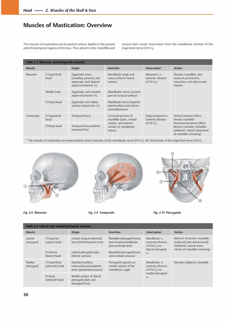
8/15/2019 Head and Neck Anatomy for Dental Medicine - Thieme; (January 26, 2010)
http://slidepdf.com/reader/full/head-and-neck-anatomy-for-dental-medicine-thieme-january-26-2010 43/384
②
①
③
④
⑥
⑦
⑤
⑧
Table 2.3 Masseter and temporalis muscles
Muscle Origin Insertion Innervation* Action
Masseter ① Superficial
head
Zygomatic bone
(maxillary process) and
zygomatic arch (lateral
aspect of anterior ⅔)
Mandibular angle and
ramus (inferior lateral
surface)
Masseteric n.
(anterior division
of CN V3)
Elevates mandible; also
assists in protraction,
retraction, and side-to-side
motion
Middle head Zygomatic arch (medial
aspect of anterior ⅔)
Mandibular ramus (central
part of occlusal surface)
② Deep head Zygomatic arch (deep
surface of posterior ⅓)
Mandibular ramus (superior
lateral surface) and inferior
coronoid process
Temporalis ③ Superficial
head
Temporal fascia Coronoid process of
mandible (apex, medial
surface, and anterior
surface of mandibular
ramus)
Deep temporal nn.
(anterior division
of CN V3)
Vertical (anterior) fibers:
Elevate mandible
Horizontal (posterior) fibers:
Retract (retrude) mandible
Unilateral: Lateral movement
of mandible (chewing)
④ Deep head Temporal fossa (inferior
temporal line)
* The muscles of mastication are innervated by motor branches of the mandibular nerve (CN V 3), the 3rd division of the trigeminal nerve (CN V).
Table 2.4 Lateral and medial pterygoid muscles
Muscle Origin Insertion Innervation Action
Lateral
pterygoid
⑤ Superior
(upper) head
Greater wing of sphenoid
bone (infratemporal crest)
Mandible (pterygoid fovea)
and temporomandibular
joint (articular disk)
Mandibular n.
(anterior division
of CN V3) via
lateral pterygoid
n.
Bilateral: Protrudes mandible
(pulls articular disk forward)
Unilateral: Lateral move-
ments of mandible (chewing)⑥ Inferior
(lower) head
Lateral pterygoid plate
(lateral surface)
Mandible (pterygoid fovea
and condylar process)
Medial
pterygoid
⑦ Superficial
(external) head
Maxilla (maxillary
tuberosity) and palatine
bone (pyramidal process)
Pterygoid rugosity on
medial surface of the
mandibular angle
Mandibular n.
(anterior division
of CN V3) via
medial pterygoid
n.
Elevates (adducts) mandible
⑧ Deep
(internal) head
Medial surface of lateral
pterygoid plate and
pterygoid fossa
The muscles of mastication are located at various depths in the parotid
and infratemporal regions of the face. They attach to the mandible and
receive their motor innervation from the mandibular division of the
trigeminal nerve (CN V3).
Fig. 2.8 Masseter Fig. 2.9 Temporalis Fig. 2.10 Pterygoids
30
Head 2. M uscles of the Skull & Face
Muscles of Mastication: Overview
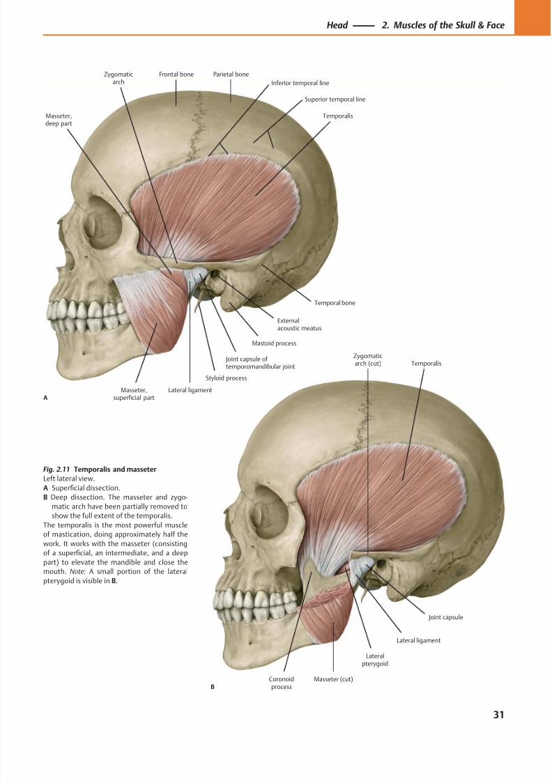
8/15/2019 Head and Neck Anatomy for Dental Medicine - Thieme; (January 26, 2010)
http://slidepdf.com/reader/full/head-and-neck-anatomy-for-dental-medicine-thieme-january-26-2010 44/384
Coronoidprocess
Joint capsule
Lateralpterygoid
Masseter (cut)
Lateral ligament
Temporalis
B
Zygomaticarch (cut)
Frontal bone Parietal boneZygomaticarch
Externalacoustic meatus
Mastoid process
Joint capsule of temporomandibular joint
Lateral ligament
Styloid process
Masseter,deep part
Masseter,superficial part
Temporalis
A
Temporal bone
Inferior temporal line
Superior temporal line
Fig. 2.11 Temporalis and masseter
Left lateral view.
A Superficial dissection.
B Deep dissection. The masseter and zygo-
matic arch have been partially removed to
show the full extent of the temporalis.
The temporalis is the most powerful muscle
of mastication, doing approximately half the
work. It works with the masseter (consistingof a superficial, an intermediate, and a deep
part) to elevate the mandible and close the
mouth. Note: A small portion of the lateral
pterygoid is visible in B.
31
Head 2. Muscles of the Skull & Face
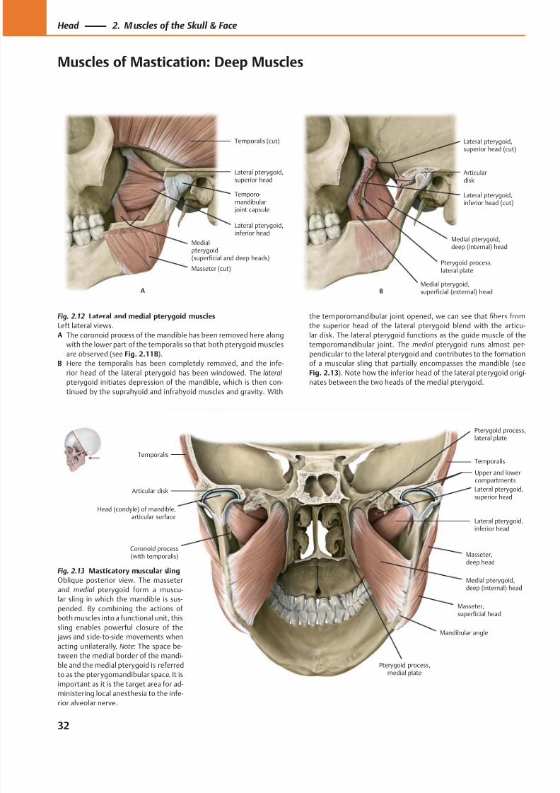
8/15/2019 Head and Neck Anatomy for Dental Medicine - Thieme; (January 26, 2010)
http://slidepdf.com/reader/full/head-and-neck-anatomy-for-dental-medicine-thieme-january-26-2010 45/384
Masseter (cut)
Medialpterygoid(superficial and deep heads)
Lateral pterygoid,superior head
Temporalis (cut)
A
Lateral pterygoid,inferior head
Temporo-mandibular joint capsule
Pterygoid process,lateral plate
Medial pterygoid,deep (internal) head
Lateral pterygoid,inferior head (cut)
Articulardisk
Lateral pterygoid,superior head (cut)
BMedial pterygoid,superficial (external) head
Articular disk
Head (condyle) of mandible, articular surface
Masseter,superficial head
Medial pterygoid,deep (internal) head
Masseter,deep head
Lateral pterygoid,inferior head
Lateral pterygoid,superior head
TemporalisTemporalis
Coronoid process
(with temporalis)
Pterygoid process,lateral plate
Mandibular angle
Pterygoid process,medial plate
Upper and lowercompartments
Fig. 2.12 Lateral and medial pterygoid muscles
Left lateral views.
A The coronoid process of the mandible has been removed here along
with the lower part of the temporalis so that both pterygoid muscles
are observed (see Fig. 2.11B).
B Here the temporalis has been completely removed, and the infe-
rior head of the lateral pterygoid has been windowed. The lateral
pterygoid initiates depression of the mandible, which is then con-
tinued by the suprahyoid and infrahyoid muscles and gravity. With
the temporomandibular joint opened, we can see that fibers from
the superior head of the lateral pterygoid blend with the articu-
lar disk. The lateral pterygoid functions as the guide muscle of the
temporomandibular joint. The medial pterygoid runs almost per-
pendicular to the lateral pterygoid and contributes to the formation
of a muscular sling that partially encompasses the mandible (see
Fig. 2.13). Note how the inferior head of the lateral pterygoid origi-
nates between the two heads of the medial pterygoid.
Fig. 2.13 Masticatory muscular sling
Oblique posterior view. The masseter
and medial pterygoid form a muscu-
lar sling in which the mandible is sus-
pended. By combining the actions of
both muscles into a functional unit, this
sling enables powerful closure of the
jaws and s ide- to-side movements when
acting unilaterally. Note: The space be-
tween the medial border of the mandi-
ble and the medial pterygoid is referred
to as the pterygomandibular space. It is
important as it is the target area for ad-
ministering local anesthesia to the infe-rior alveolar nerve.
32
Head 2. M uscles of the Skull & Face
Muscles of Mastication: Deep Muscles
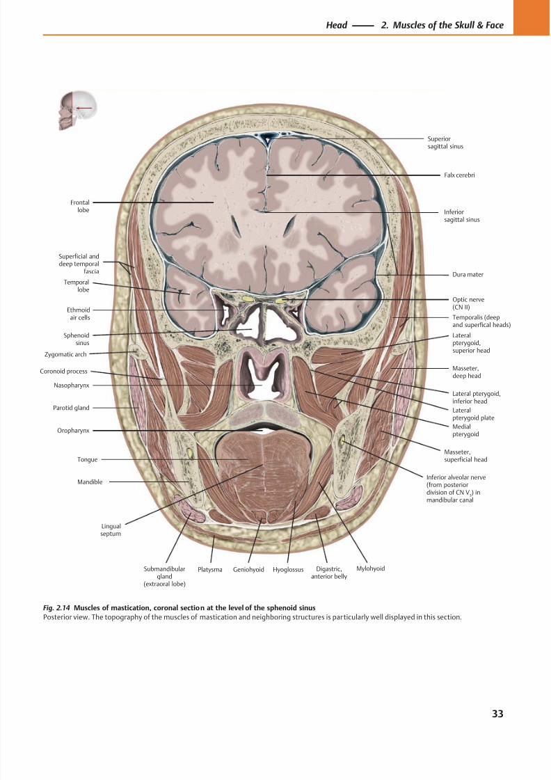
8/15/2019 Head and Neck Anatomy for Dental Medicine - Thieme; (January 26, 2010)
http://slidepdf.com/reader/full/head-and-neck-anatomy-for-dental-medicine-thieme-january-26-2010 46/384
Ethmoidair cells
Sphenoidsinus
Nasopharynx
Parotid gland
Oropharynx
Tongue
Submandibulargland
(extraoral lobe)
MylohyoidDigastric,anterior belly
Platysma
Masseter,superficial head
Masseter,deep head
Lateral pterygoid,inferior head
Temporalis (deepand superfical heads)
Lateralpterygoid,superior head
Medialpterygoid
Superiorsagittal sinus
Dura materTemporal
lobe
Optic nerve(CN II)
Frontallobe
Falx cerebri
Mandible
Geniohyoid
Inferior alveolar nerve(from posteriordivision of CN V
3) in
mandibular canal
Hyoglossus
Lingualseptum
Superficial anddeep temporal
fascia
Zygomatic arch
Coronoid process
Inferiorsagittal sinus
Lateralpterygoid plate
Fig. 2.14 Muscles of mastication, coronal section at the level of the sphenoid sinus
Posterior view. The topography of the muscles of mastication and neighboring structures is particularly well displayed in this section.
33
Head 2. Muscles of the Skull & Face
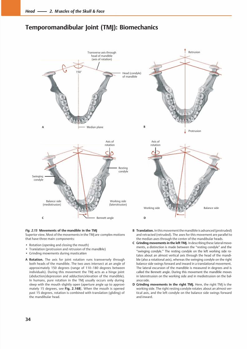
8/15/2019 Head and Neck Anatomy for Dental Medicine - Thieme; (January 26, 2010)
http://slidepdf.com/reader/full/head-and-neck-anatomy-for-dental-medicine-thieme-january-26-2010 47/384
Median plane
Head (condyle)of mandible
Transverse axis throughhead of mandible(axis of rotation)
150°
A
Protrusion
Retrusion
B
Working side(laterotrusion)
Balance side(mediotrusion)
Bennett angle
Axis of rotation
Restingcondyle
Swingingcondyle
C
Balance sideWorking side
D
Axis of rotation
Fig. 2.15 Movements of the mandible in the TMJ
Superior view. Most of the movements in the TMJ are complex motions
that have three main components:
• Rotation (opening and closing the mouth)• Translation (protrusion and retrusion of the mandible)
• Grinding movements during mastication
A Rotation. The axis for joint rotation runs transversely through
both heads of the mandible. The two axes intersect at an angle of
approximately 150 degrees (range of 110–180 degrees between
individuals). During this movement the TMJ acts as a hinge joint
(abduction/depression and adduction/elevation of the mandible).
In humans, pure rotation in the TMJ usually occurs only during
sleep with the mouth slightly open (aperture angle up to approxi-
mately 15 degrees, see Fig. 2.16B). When the mouth is opened
past 15 degrees, rotation is combined with translation (gliding) of
the mandibular head.
B Translation. In this movement the mandible is advanced (protruded)
and retracted (retruded). The axes for this movement are parallel to
the median axes through the center of the mandibular heads.
C Grinding movements in the left TMJ. In describing these lateral move-ments, a distinction is made between the “resting condyle” and the
“swinging condyle.” The resting condyle on the left working side ro-
tates about an almost vertical axis through the head of the mandi-
ble (also a rotational axis), whereas the swinging condyle on the right
balance side swings forward and inward in a translational movement.
The lateral excursion of the mandible is measured in degrees and is
called the Bennett angle. During this movement the mandible moves
in laterotrusion on the working side and in mediotrusion on the bal-
ance side.
D Grinding movements in the right TMJ. Here, the right TMJ is the
working side. The right resting condyle rotates about an almost ver-
tical axis, and the left condyle on the balance side swings forward
and inward.
34
Head 2. M uscles of the Skull & Face
Temporomandibular Joint (TMJ): Biomechanics
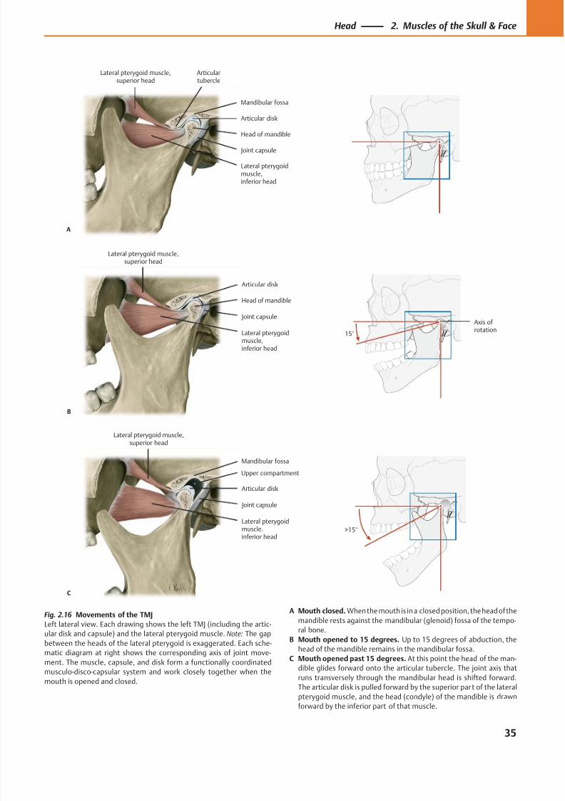
8/15/2019 Head and Neck Anatomy for Dental Medicine - Thieme; (January 26, 2010)
http://slidepdf.com/reader/full/head-and-neck-anatomy-for-dental-medicine-thieme-january-26-2010 48/384
Lateral pterygoidmuscle,inferior head
Head of mandible
Joint capsule
Articular disk
Articulartubercle
Lateral pterygoid muscle,superior head
A
Mandibular fossa
Lateral pterygoidmuscle,inferior head
Joint capsule
Head of mandible
Lateral pterygoid muscle,superior head
B
Articular disk
Axis ofrotation
15°
Lateral pterygoidmuscle,inferior head
Joint capsule
Articular disk
Lateral pterygoid muscle,superior head
C
Mandibular fossa
>15°
Upper compartment
Fig. 2.16 Movements of the TMJ
Left lateral view. Each drawing shows the left TMJ (including the artic-
ular disk and capsule) and the lateral pterygoid muscle. Note: The gap
between the heads of the lateral pterygoid is exaggerated. Each sche-
matic diagram at right shows the corresponding axis of joint move-
ment. The muscle, capsule, and disk form a functionally coordinated
musculo-disco-capsular system and work closely together when the
mouth is opened and closed.
A Mouth closed. When the mouth is in a closed position, the head of the
mandible rests against the mandibular (glenoid) fossa of the tempo-
ral bone.
B Mouth opened to 15 degrees. Up to 15 degrees of abduction, the
head of the mandible remains in the mandibular fossa.
C Mouth opened past 15 degrees. At this point the head of the man-
dible glides forward onto the articular tubercle. The joint axis that
runs transversely through the mandibular head is shifted forward.
The articular disk is pulled forward by the superior part of the lateral
pterygoid muscle, and the head (condyle) of the mandible is drawn
forward by the inferior part of that muscle.
35
Head 2. Muscles of the Skull & Face
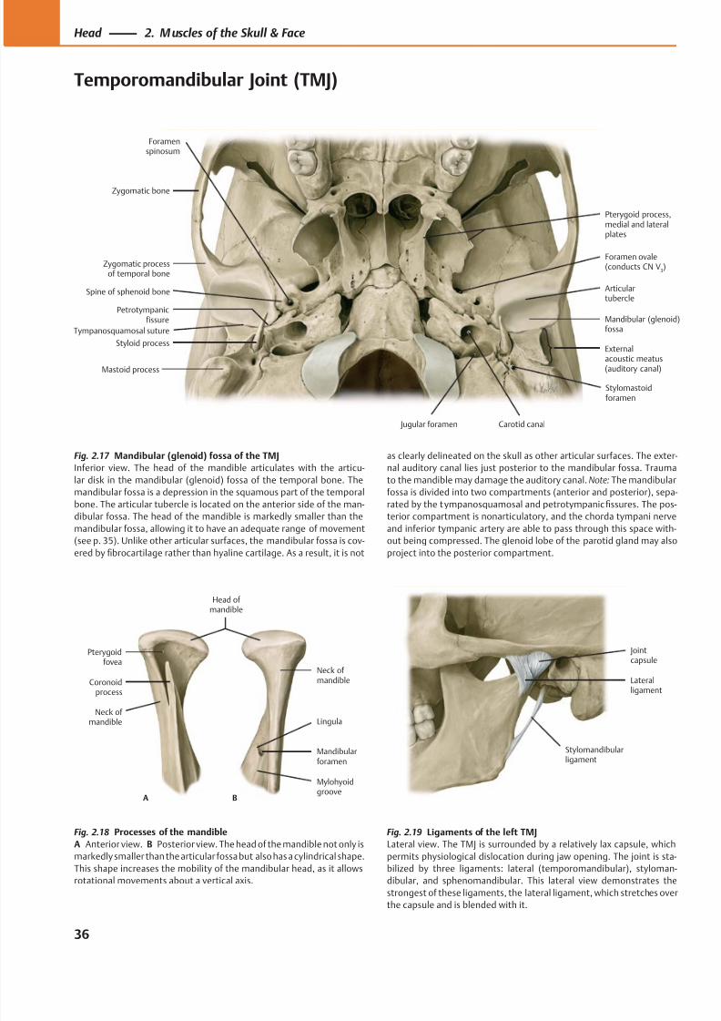
8/15/2019 Head and Neck Anatomy for Dental Medicine - Thieme; (January 26, 2010)
http://slidepdf.com/reader/full/head-and-neck-anatomy-for-dental-medicine-thieme-january-26-2010 49/384
Petrotympanicfissure
Articulartubercle
Mandibular (glenoid)fossa
External
acoustic meatus(auditory canal)
Zygomatic processof temporal bone
Styloid process
Mastoid process
Foramen ovale(conducts CN V
3)
Pterygoid process,medial and lateralplates
Zygomatic bone
Spine of sphenoid bone
Foramenspinosum
Tympanosquamosal suture
Stylomastoidforamen
Carotid canal Jugular foramen
Stylomandibularligament
Jointcapsule
Lateralligament
Mylohyoidgroove
Mandibularforamen
Lingula
Neck ofmandible
Neck of mandible
Coronoidprocess
Pterygoidfovea
Head of mandible
A B
Fig. 2.17 Mandibular (glenoid) fossa of the TMJ
Inferior view. The head of the mandible articulates with the articu-
lar disk in the mandibular (glenoid) fossa of the temporal bone. The
mandibular fossa is a depression in the squamous part of the temporal
bone. The articular tubercle is located on the anterior side of the man-
dibular fossa. The head of the mandible is markedly smaller than the
mandibular fossa, allowing it to have an adequate range of movement
(see p. 35). Unlike other articular surfaces, the mandibular fossa is cov-
ered by fibrocartilage rather than hyaline cartilage. As a result, it is not
Fig. 2.18 Processes of the mandible
A Anterior view. B Posterior view. The head of the mandible not only is
markedly smaller than the articular fossa but also has a cylindrical shape.
This shape increases the mobility of the mandibular head, as it allows
rotational movements about a vertical axis.
Fig. 2.19 Ligaments of the left TMJ
Lateral view. The TMJ is surrounded by a relatively lax capsule, which
permits physiological dislocation during jaw opening. The joint is sta-
bilized by three ligaments: lateral (temporomandibular), styloman-
dibular, and sphenomandibular. This lateral view demonstrates the
strongest of these ligaments, the lateral ligament, which stretches overthe capsule and is blended with it.
as clearly delineated on the skull as other articular surfaces. The exter-
nal auditory canal lies just posterior to the mandibular fossa. Trauma
to the mandible may damage the auditory canal. Note: The mandibular
fossa is divided into two compartments (anterior and posterior), sepa-
rated by the tympanosquamosal and petrotympanic fissures. The pos-
terior compartment is nonarticulatory, and the chorda tympani nerve
and inferior tympanic artery are able to pass through this space with-
out being compressed. The glenoid lobe of the parotid gland may also
project into the posterior compartment.
36
Head 2. M uscles of the Skull & Face
Temporomandibular Joint (TMJ)
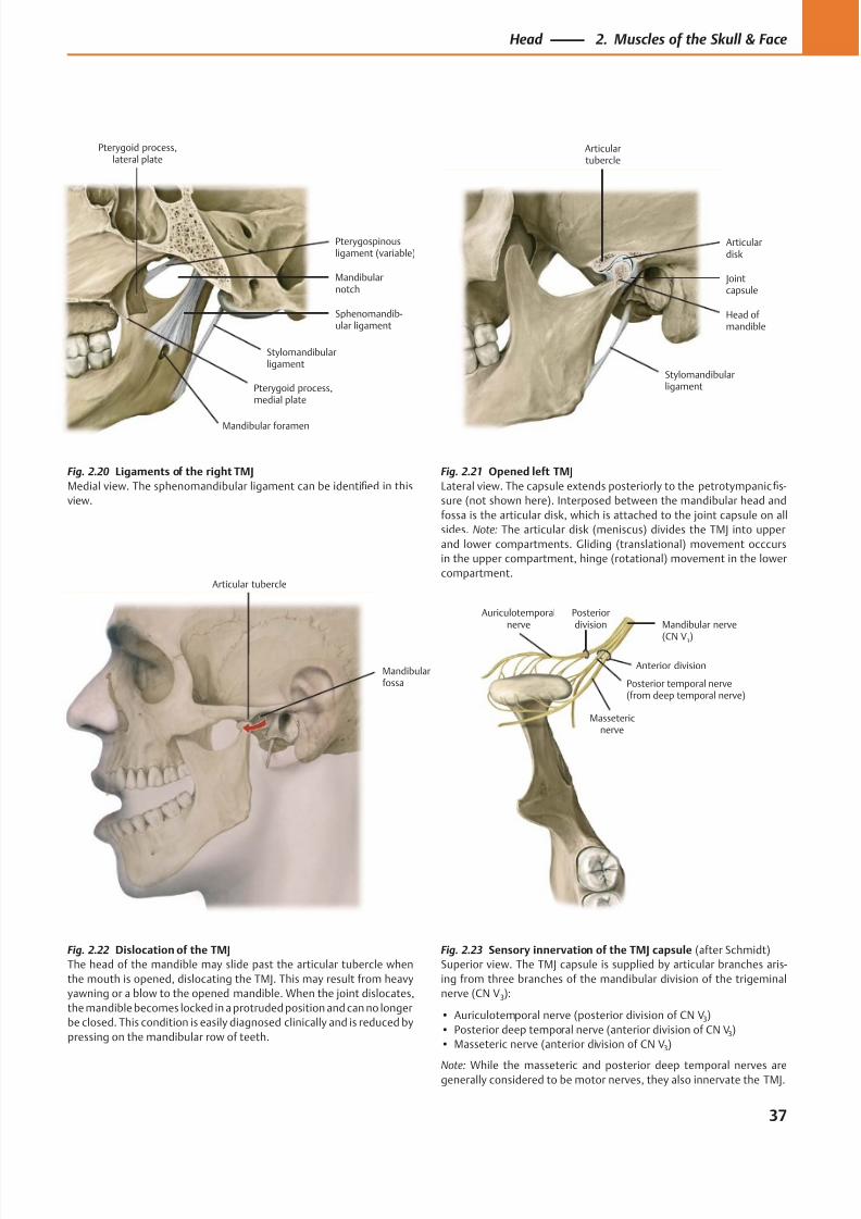
8/15/2019 Head and Neck Anatomy for Dental Medicine - Thieme; (January 26, 2010)
http://slidepdf.com/reader/full/head-and-neck-anatomy-for-dental-medicine-thieme-january-26-2010 50/384
Pterygoid process,medial plate
Pterygoid process,lateral plate
Stylomandibularligament
Sphenomandib-ular ligament
Mandibularnotch
Pterygospinousligament (variable)
Mandibular foramen
Jointcapsule
Stylomandibularligament
Head ofmandible
Articulardisk
Articulartubercle
Mandibularfossa
Articular tubercle
Mandibular nerve
(CN V3)
Massetericnerve
Posterior temporal nerve(from deep temporal nerve)
Auriculotemporalnerve
Posteriordivision
Anterior division
Fig. 2.23 Sensory innervation of the TMJ capsule (after Schmidt)
Superior view. The TMJ capsule is supplied by articular branches aris-
ing from three branches of the mandibular division of the trigeminal
nerve (CN V3):
• Auriculotemporal nerve (posterior division of CN V3)
• Posterior deep temporal nerve (anterior division of CN V3)
• Masseteric nerve (anterior division of CN V3)
Note: While the masseteric and posterior deep temporal nerves aregenerally considered to be motor nerves, they also innervate the TMJ.
Fig. 2.20 Ligaments of the right TMJ
Medial view. The sphenomandibular ligament can be identified in this
view.
Fig. 2.21 Opened left TMJ
Lateral view. The capsule extends posteriorly to the petrotympanic fis-
sure (not shown here). Interposed between the mandibular head and
fossa is the articular disk, which is attached to the joint capsule on all
sides. Note: The articular disk (meniscus) divides the TMJ into upper
and lower compartments. Gliding (translational) movement occcurs
in the upper compartment, hinge (rotational) movement in the lower
compartment.
Fig. 2.22 Dislocation of the TMJ
The head of the mandible may slide past the articular tubercle when
the mouth is opened, dislocating the TMJ. This may result from heavy
yawning or a blow to the opened mandible. When the joint dislocates,
the mandible becomes locked in a protruded position and can no longer
be closed. This condition is easily diagnosed clinically and is reduced by
pressing on the mandibular row of teeth.
37
Head 2. Muscles of the Skull & Face
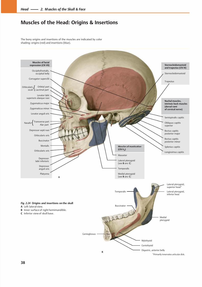
8/15/2019 Head and Neck Anatomy for Dental Medicine - Thieme; (January 26, 2010)
http://slidepdf.com/reader/full/head-and-neck-anatomy-for-dental-medicine-thieme-january-26-2010 51/384
Trapezius
Sternocleidomastoid
Longissimus capitis
Splenius capitis
Rectus capitisposterior minor
Rectus capitisposterior major
Obliquus capitissuperior
Semispinalis capitis
Platysma
Depressoranguli oris
Depressorlabii inferioris
Orbicularis oris
Mentalis
Buccinator
Zygomaticus major
Orbicularis oris
Transverse part
Alar part
Zygomaticus minor
Levator anguli oris
Levator labiisuperioris alaeque nasi
Orbital part
Lacrimal part
Corrugator supercilii
Occipitofrontalis,occipital belly
Muscles of facialexpression (CN VII)
Nuchal muscles,intrinsic back muscles(dorsal ramiof cervical nerve)
Sternocleidomastoidand trapezius (CN XI)
Depressor septi nasi
Lateral pterygoid(see B and C)
Masseter
Temporalis
Muscles of mastication(CN V
3)
Medial pterygoid(see B and C)A
Orbicularisoculi
Nasalis
Genioglossus
Geniohyoid
Mylohyoid
Medialpterygoid
Lateral pterygoid,superior head*
Temporalis
Buccinator
Digastric, anterior bellyB
Lateral pterygoid,inferior head
*Primarily innervates articular disk.
Fig. 2.24 Origins and insertions on the skull
A Left lateral view.
B Inner surface of right hemimandible.
C Inferior view of skull base.
38
Head 2. M uscles of the Skull & Face
Muscles of the Head: Origins & Insertions
The bony origins and insertions of the muscles are indicated by color
shading: origins (red) and insertions (blue).
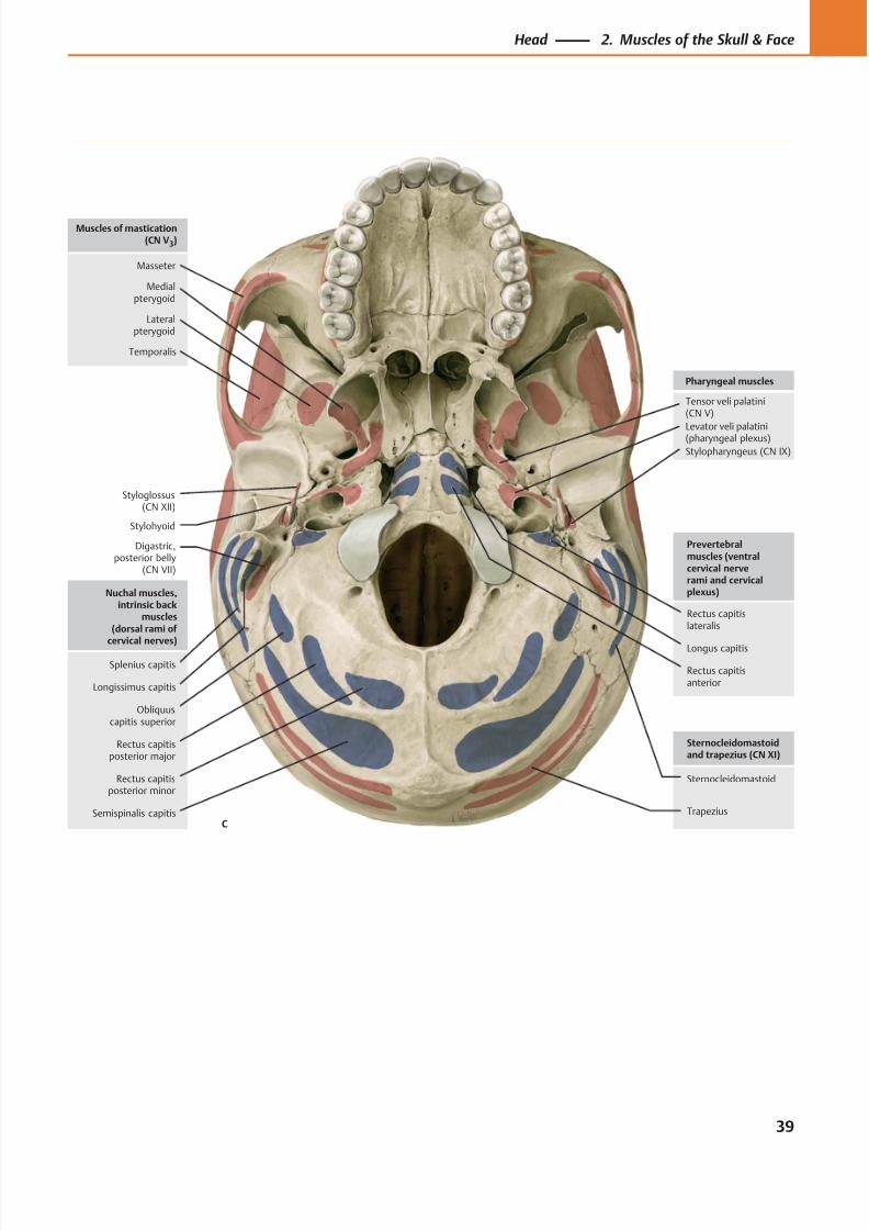
8/15/2019 Head and Neck Anatomy for Dental Medicine - Thieme; (January 26, 2010)
http://slidepdf.com/reader/full/head-and-neck-anatomy-for-dental-medicine-thieme-january-26-2010 52/384
Digastric,posterior belly
(CN VII)
Styloglossus(CN XII)
Trapezius
Sternocleidomastoid
Stylohyoid
Tensor veli palatini(CN V)
Stylopharyngeus (CN IX)
Levator veli palatini(pharyngeal plexus)
Pharyngeal muscles
Sternocleidomastoidand trapezius (CN XI)
Lateralpterygoid
Masseter
Temporalis
Muscles of mastication(CN V3)
Medialpterygoid
Splenius capitis
Rectus capitisposterior minor
Rectus capitisposterior major
Obliquuscapitis superior
Semispinalis capitis
Nuchal muscles,intrinsic back
muscles(dorsal rami of
cervical nerves)
Rectus capitislateralis
Rectus capitisanterior
Longus capitis
Prevertebralmuscles (ventralcervical nerverami and cervicalplexus)
C
Longissimus capitis
39
Head 2. Muscles of the Skull & Face
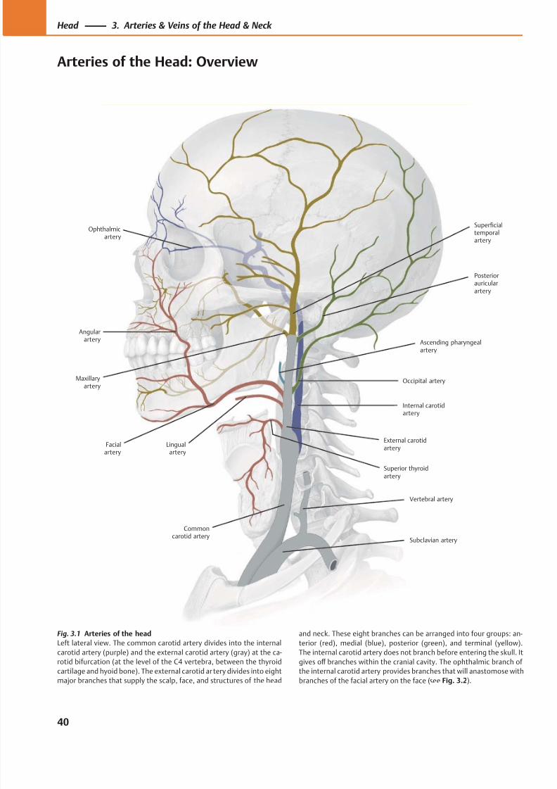
8/15/2019 Head and Neck Anatomy for Dental Medicine - Thieme; (January 26, 2010)
http://slidepdf.com/reader/full/head-and-neck-anatomy-for-dental-medicine-thieme-january-26-2010 53/384
Vertebral artery
Commoncarotid artery
Internal carotid
artery
Facialartery
External carotidartery
Ophthalmicartery
Subclavian artery
Angularartery
Maxillaryartery
Lingualartery
Superficialtemporalartery
Posteriorauricularartery
Ascending pharyngealartery
Occipital artery
Superior thyroidartery
Fig. 3.1 Arteries of the head
Left lateral view. The common carotid artery divides into the internal
carotid artery (purple) and the external carotid artery (gray) at the ca-
rotid bifurcation (at the level of the C4 vertebra, between the thyroid
cartilage and hyoid bone). The external carotid ar tery divides into eight
major branches that supply the scalp, face, and structures of the head
and neck. These eight branches can be arranged into four groups: an-
terior (red), medial (blue), posterior (green), and terminal (yellow).
The internal carotid artery does not branch before entering the skull. It
gives off branches within the cranial cavity. The ophthalmic branch of
the internal carotid artery provides branches that will anastomose with
branches of the facial artery on the face (see Fig. 3.2).
40
Head 3. Arteries & Veins of the Head & Neck
Arteries of the Head: Overview
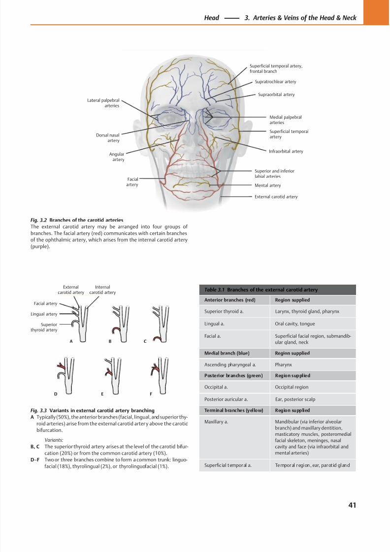
8/15/2019 Head and Neck Anatomy for Dental Medicine - Thieme; (January 26, 2010)
http://slidepdf.com/reader/full/head-and-neck-anatomy-for-dental-medicine-thieme-january-26-2010 54/384
Superiorthyroid artery
Lingual artery
Facial artery
Externalcarotid artery
Internalcarotid artery
A B C
D E F
Dorsal nasalartery
Lateral palpebralarteries
Angularartery
Facialartery
Superficial temporal artery,frontal branch
Supratrochlear artery
Supraorbital artery
Superficial temporalartery
Medial palpebralarteries
Infraorbital artery
Superior and inferiorlabial arteries
Mental artery
External carotid artery
Table 3.1 Branches of the external carotid artery
Anterior branches (red) Region supplied
Superior thyroid a. Larynx, thyroid gland, pharynx
Lingual a. Oral cavity, tongue
Facial a. Superficial facial region, submandib-
ular gland, neck
Medial branch (blue) Region supplied
Ascending pharyngeal a. Pharynx
Posterior branches (green) Region supplied
Occipital a. Occipital region
Posterior auricular a. Ear, posterior scalp
Terminal branches (yellow) Region supplied
Maxillary a. Mandibular (via inferior alveolar
branch) and maxillary dentition,
masticatory muscles, posteromedial
facial skeleton, meninges, nasal
cavity and face (via infraorbital and
mental arteries)
Superficial temporal a. Temporal region, ear, parot id gland
Fig. 3.3 Variants in external carotid artery branching
A Typically (50%), the anterior branches (facial, lingual, and superior thy-
roid arteries) arise from the external carotid arter y above the carotid
bifurcation.
Variants:
B, C The superior thyroid artery arises at the level of the carotid bifur-
cation (20%) or from the common carotid artery (10%).
D–F Two or three branches combine to form a common trunk: linguo-
facial (18%), thyrolingual (2%), or thyrolinguofacial (1%).
Fig. 3.2 Branches of the carotid arteries
The external carotid artery may be arranged into four groups of
branches. The facial artery (red) communicates with certain branches
of the ophthalmic artery, which arises from the internal carotid artery
(purple).
41
Head 3. Arteries & Veins of the Head & Neck
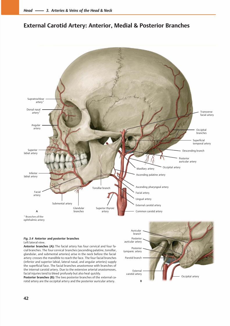
8/15/2019 Head and Neck Anatomy for Dental Medicine - Thieme; (January 26, 2010)
http://slidepdf.com/reader/full/head-and-neck-anatomy-for-dental-medicine-thieme-january-26-2010 55/384
Superficialtemporal artery
Angularartery
Superiorlabial artery
Inferiorlabial artery
Maxillary artery
Glandularbranches
Facial artery
Posteriorauricular artery
Occipital artery
Descending branch
Occipitalbranches
Common carotid arterySuperior thyroid
artery
External carotid arterySubmental artery
Lingual artery
Ascending pharyngeal artery
Ascending palatine artery
Tonsillar branch
Supratrochlearartery*
Dorsal nasal
artery*
A
Facialartery
Transverse
facial artery
Parotid branch
Externalcarotid artery
Occipital artery
Posteriorauricular artery
Auricularbranch
Posteriortympanic artery
B
Fig. 3.4 Anterior and posterior branches
Left lateral view.
Anterior branches (A): The facial artery has four cervical and four fa-
cial branches. The four cervical branches (ascending palatine, tonsillar,
glandular, and submental arteries) arise in the neck before the facial
artery crosses the mandible to reach the face. The four facial branches
(inferior and superior labial, lateral nasal, and angular arteries) supply
the superficial face. The facial branches anastomose with branches of
the internal carotid artery. Due to the extensive arterial anastomoses,
facial injuries tend to bleed profusely but also heal quickly.
Posterior branches (B): The two posterior branches of the external ca-
rotid artery are the occipital artery and the posterior auricular artery.
* Branches of theophthalmic artery
42
Head 3. Arteries & Veins of the Head & Neck
External Carotid Artery: Anterior, Medial & Posterior Branches
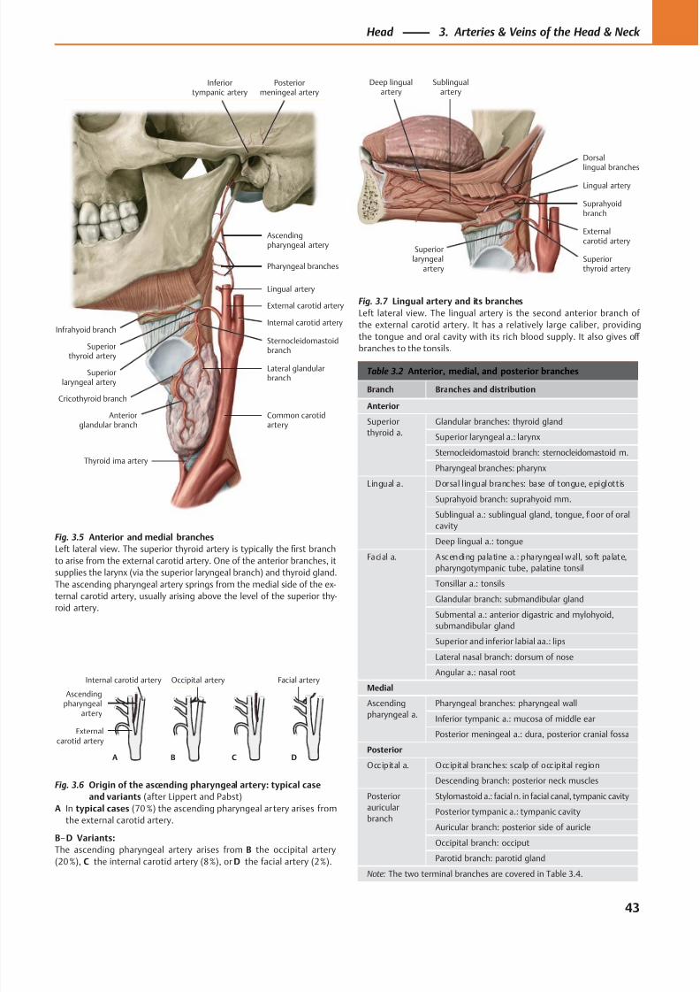
8/15/2019 Head and Neck Anatomy for Dental Medicine - Thieme; (January 26, 2010)
http://slidepdf.com/reader/full/head-and-neck-anatomy-for-dental-medicine-thieme-january-26-2010 56/384
Ascendingpharyngeal
artery
A B C D
Externalcarotid artery
Occipital arteryInternal carotid artery Facial artery
Infrahyoid branch
Superiorlaryngeal artery
Cricothyroid branch
Anteriorglandular branch
Thyroid ima artery
Common carotidartery
Lateral glandularbranch
Sternocleidomastoidbranch
Internal carotid artery
External carotid artery
Superiorthyroid artery
Lingual artery
Ascendingpharyngeal artery
Pharyngeal branches
Posteriormeningeal artery
Inferiortympanic artery
Deep lingualartery
Sublingualartery
Superiorthyroid artery
Externalcarotid artery
Lingual artery
Suprahyoidbranch
Dorsallingual branches
Superiorlaryngeal
artery
Table 3.2 Anterior, medial, and posterior branches
Branch Branches and distribution
Anterior
Superior
thyroid a.
Glandular branches: thyroid gland
Superior laryngeal a.: larynx
Sternocleidomastoid branch: sternocleidomastoid m.
Pharyngeal branches: pharynx
Lingual a. Dorsal lingual branches: base of tongue, epiglottis
Suprahyoid branch: suprahyoid mm.
Sublingual a.: sublingual gland, tongue, floor of oral
cavity
Deep lingual a.: tongue
Facial a. Ascending palatine a.: pharyngeal wall, soft palate,
pharyngotympanic tube, palatine tonsil
Tonsillar a.: tonsils
Glandular branch: submandibular gland
Submental a.: anterior digastric and mylohyoid,
submandibular gland
Superior and inferior labial aa.: lips
Lateral nasal branch: dorsum of nose
Angular a.: nasal root
Medial
Ascending
pharyngeal a.
Pharyngeal branches: pharyngeal wall
Inferior tympanic a.: mucosa of middle ear
Posterior meningeal a.: dura, posterior cranial fossa
Posterior
Occipital a. Occipital branches: scalp of occipital region
Descending branch: posterior neck muscles
Posterior
auricular
branch
Stylomastoid a.: facial n. in facial canal, tympanic cavity
Posterior tympanic a.: tympanic cavity
Auricular branch: posterior side of auricle
Occipital branch: occiput
Parotid branch: parotid gland
Note: The two terminal branches are covered in Table 3.4.
Fig. 3.5 Anterior and medial branches
Left lateral view. The superior thyroid artery is typically the first branch
to arise from the external carotid artery. One of the anterior branches, it
supplies the larynx (via the superior laryngeal branch) and thyroid gland.
The ascending pharyngeal artery springs from the medial side of the ex-
ternal carotid artery, usually arising above the level of the superior thy-
roid artery.
Fig. 3.6 Origin of the ascending pharyngeal artery: typical case
and variants (after Lippert and Pabst)
A In typical cases (70 %) the ascending pharyngeal ar tery arises from
the external carotid artery.
B–D Variants:
The ascending pharyngeal artery arises from B the occipital artery
(20 %), C the internal carotid artery (8 %), or D the facial artery (2 %).
Fig. 3.7 Lingual artery and its branches
Left lateral view. The lingual artery is the second anterior branch of
the external carotid artery. It has a relatively large caliber, providing
the tongue and oral cavity with its rich blood supply. It also gives off
branches to the tonsils.
43
Head 3. Arteries & Veins of the Head & Neck
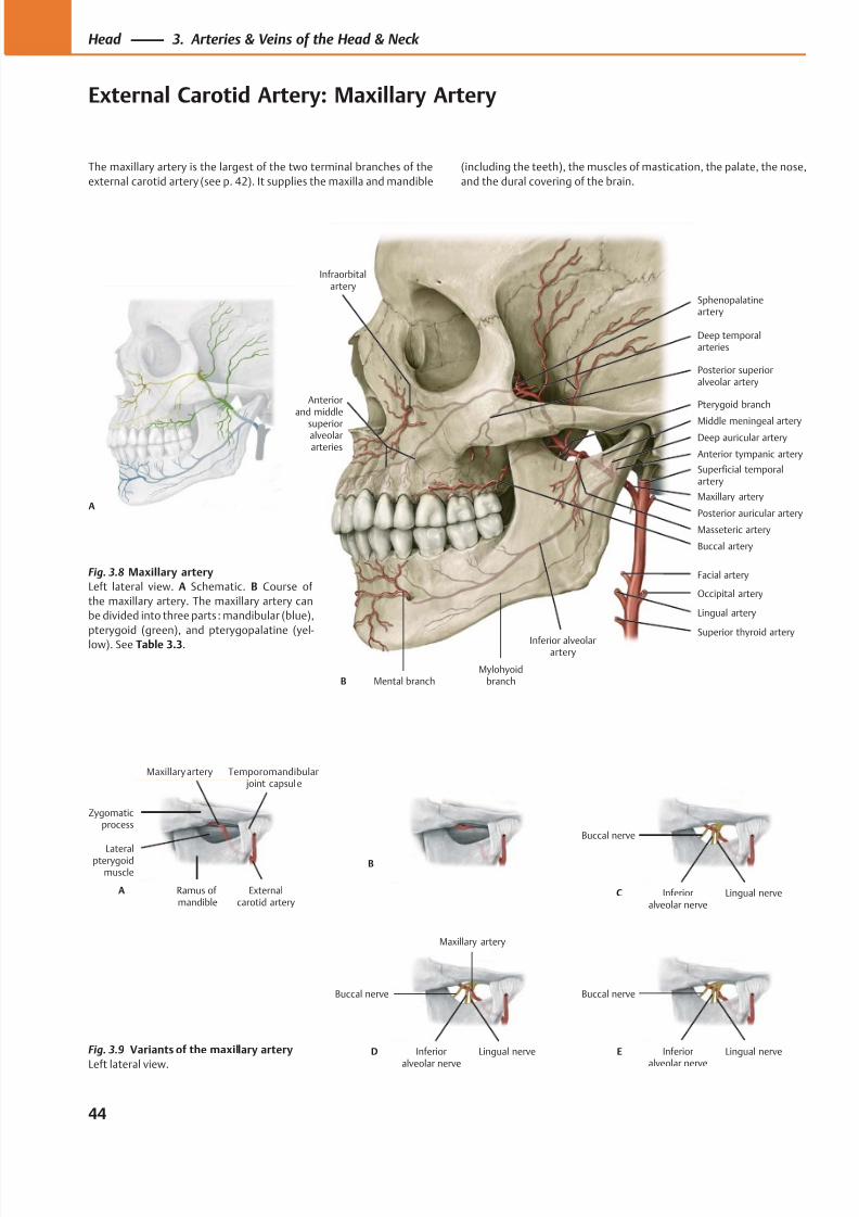
8/15/2019 Head and Neck Anatomy for Dental Medicine - Thieme; (January 26, 2010)
http://slidepdf.com/reader/full/head-and-neck-anatomy-for-dental-medicine-thieme-january-26-2010 57/384
Mental branch
Pterygoid branch
Inferior alveolarartery
Mylohyoidbranch
Maxillary artery
Masseteric artery
Buccal artery
Deep temporalarteries
Sphenopalatineartery
Posterior superioralveolar artery
Anterior tympanic artery
Deep auricular arteryMiddle meningeal artery
B
Superficial temporalartery
Posterior auricular artery
Facial artery
Occipital artery
Lingual artery
Superior thyroid artery
Infraorbitalartery
Anteriorand middle
superioralveolararteries
A
Zygomaticprocess
Ramus ofmandible
Externalcarotid artery
Temporomandibular joint capsule
Maxillary artery
Lateralpterygoidmuscle
A
B
C
Buccal nerve
Lingual nerveInferioralveolar nerve
Maxillary artery
Lingual nerveInferior
alveolar nerve
Buccal nerve
D E
Buccal nerve
Lingual nerveInferior
alveolar nerve
Fig. 3.8 Maxillary artery
Left lateral view. A Schematic. B Course of
the maxillary artery. The maxillary artery can
be divided into three parts : mandibular (blue),
pterygoid (green), and pterygopalatine (yel-
low). See Table 3.3.
Fig. 3.9 Variants of the maxillary artery
Left lateral view.
44
Head 3. Arteries & Veins of the Head & Neck
External Carotid Artery: Maxillary Artery
The maxillary artery is the largest of the two terminal branches of the
external carotid artery (see p. 42). It supplies the maxilla and mandible
(including the teeth), the muscles of mastication, the palate, the nose,
and the dural covering of the brain.
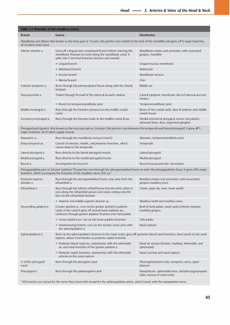
8/15/2019 Head and Neck Anatomy for Dental Medicine - Thieme; (January 26, 2010)
http://slidepdf.com/reader/full/head-and-neck-anatomy-for-dental-medicine-thieme-january-26-2010 58/384
Table 3.3 Branches of the maxillary artery
Branch Course Distribution
Mandibular part (blue): Also known as the bony part or 1st part, this portion runs medial to the neck of the mandible and gives o ff 5 major branches,
all of which enter bone.
Inferior alveolar a. Gives off a lingual and a mylohyoid branch before entering the
mandibular foramen to travel along the mandibular canal; it
splits into 2 terminal branches (incisive and mental)
Mandibular molars and premolars with associated
gingiva, mandible
• Lingual branch Lingual mucous membrane
• Mylohyoid branch Mylohyoid
• Incisive branch Mandibular incisors
• Mental branch Chin
Anterior tympanic a. Runs through the petrotympanic fissure along with the chorda
tympani
Middle ear
Deep auricular a. Travels through the wal l of the external acoust ic meatus Lateral tympanic membrane, skin of external acoust ic
meatus
• Branch to temporomandibular joint Temporomandibular joint
Middle meningeal a. Runs through the foramen spinosum to the middle cranial
cavity
Bones of the cranial vault, dura of anterior and middle
cranial fossae
Accessory meningeal a. Runs through the foramen ovale to the middle cranial fossa Medial and lateral pterygoid, tensor veli palatini,
sphenoid bone, dura, trigeminal ganglion
Pterygoid part (green): Also known as the muscular part or 2nd part, this portion runs between the temporalis and lateral pterygoid. It gives off 5
major branches, all of which supply muscle.
Masseteric a. Runs through the mandibular incisure (notch) Masseter, temporomandibular joint
Deep temporal aa. Consist of anterior, middle, and posterior branches, which
course deep to the temporalis
Temporalis
Lateral pterygoid a. Runs directly to the lateral pterygoid muscle Lateral pterygoid
Medial pterygoid a. Runs directly to the medial pterygoid muscle Medial pterygoid
Buccal a. Accompanies the buccal n. Buccal mucosa and skin, buccinator
Pterygopalatine part or 3rd part (yellow): This portion runs through the pterygomaxillaryfi
ssure to enter the pterygopalatine fossa. It gives off
6 majorbranches, which accompany the branches of the maxillary nerve (CN V2).*
Posterior superior
alveolar a.
Runs through the pterygomaxillary fissure; may arise from the
infraorbital a.
Maxillary molars and premolars, with associated
gingiva; maxillary sinus
Infraorbital a. Runs through the inferior orbital fissure into the orbit, where it
runs along the infraorbital groove and canal, exiting onto the
face via the infraorbital foramen
Cheek, upper lip, nose, lower eyelid
• Anterior and middle superior alveolar aa. Maxillary teeth and maxillary sinus
Descending palatine a. Greater palatine a.: runs via the greater (anterior) palatine
canal; in the canal it gives off several lesser palatine aa.;
continues through greater palatine foramen onto hard palate
Roof of hard palate, nasal cavity (inferior meatus),
maxillary gingiva
• Lesser palatine aa.: run via the lesser palatine foramen Soft palate
• Anastomosing branch: runs via the incisive canal; joins with
the sphenopalatine a.
Nasal septum
Sphenopalatine a. Runs via the sphenopalatine foramen to the nasal cavity; gives off posterior lateral nasal branches, then travels to the nasal
septum, where it terminates as posterior septal branches
• Posterior lateral nasal aa.: anastomose with the ethmoidal
aa. and nasal branches of the greater palatine a.
Nasal air sinuses (frontal, maxillary, ethmoidal, and
sphenoidal)
• Posterior septal branches: anastomose with the ethmoidal
arteries on the nasal septum
Nasal conchae and nasal septum
A. of the pterygoid
canal
Runs through the pterygoid canal Pharyngotympanic tube, tympanic cavity, upper
pharynx
Pharyngeal a. Runs through the palatovaginal canal Nasopharynx, sphenoidal sinus, and pharyngotympanic
tube; mucosa of nasal cavity
*All branches are named for the nerve they travel with except for the sphenopalatine artery, which travels with the nasopalatine nerve.
45
Head 3. Arteries & Veins of the Head & Neck
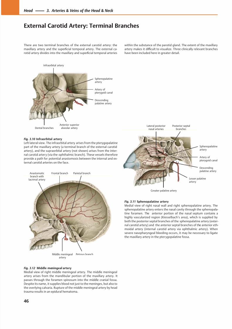
8/15/2019 Head and Neck Anatomy for Dental Medicine - Thieme; (January 26, 2010)
http://slidepdf.com/reader/full/head-and-neck-anatomy-for-dental-medicine-thieme-january-26-2010 59/384
Anastomoticbranch with
lacrimal artery
Parietal branchFrontal branch
Middle meningealartery
Petrous branch
Dental branchesAnterior superior
alveolar artery
Descendingpalatine artery
Artery of pterygoid canal
Infraorbital artery
Sphenopalatineartery
Greater palatine artery
Lesser palatineartery
Descendingpalatine artery
Artery of pterygoid canal
Sphenopalatineartery
Posterior septalbranches
Lateral posteriornasal arteries
Fig. 3.12 Middle meningeal artery
Medial view of right middle meningeal artery. The middle meningeal
artery arises from the mandibular portion of the maxillary artery. It
passes through the foramen spinosum into the middle cranial fossa.
Despite its name, it supplies blood not just to the meninges, but also to
the overlying calvaria. Rupture of the middle meningeal artery by headtrauma results in an epidural hematoma.
Fig. 3.10 Infraorbital artery
Left lateral view. The infraorbital artery arises from the pterygopalatine
part of the maxillary artery (a terminal branch of the external carotid
artery), and the supraorbital artery (not shown) arises from the inter-
nal carotid artery (via the ophthalmic branch). These vessels therefore
provide a path for potential anastomosis between the internal and ex-
ternal carotid arteries on the face.
Fig. 3.11 Sphenopalatine artery
Medial view of right nasal wall and right sphenopalatine artery. The
sphenopalatine artery enters the nasal cavity through the sphenopala-
tine foramen. The anterior portion of the nasal septum contains a
highly vascularized region (Kiesselbach’s area), which is supplied by
both the posterior septal branches of the sphenopalatine artery (exter-
nal carotid artery) and the anterior septal branches of the anterior eth-
moidal artery (internal carotid artery via ophthalmic artery). Whensevere nasopharyngeal bleeding occurs, it may be necessary to ligate
the maxillary artery in the pterygopalatine fossa.
46
Head 3. Arteries & Veins of the Head & Neck
External Carotid Artery: Terminal Branches
There are two terminal branches of the external carotid artery: the
maxillary artery and the superficial temporal artery. The external ca-
rotid artery divides into the maxillary and superficial temporal arteries
within the substance of the parotid gland. The extent of the maxillary
artery makes it diffi cult to visualize. Three clinically relevant branches
have been included here in greater detail.
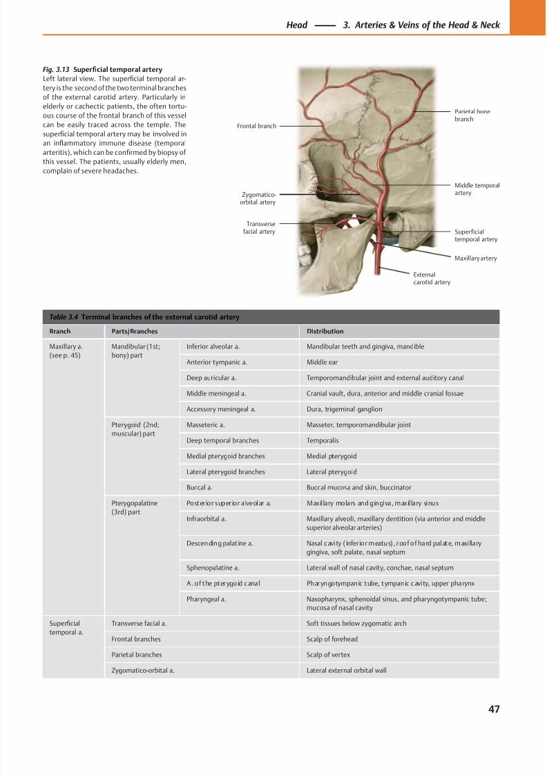
8/15/2019 Head and Neck Anatomy for Dental Medicine - Thieme; (January 26, 2010)
http://slidepdf.com/reader/full/head-and-neck-anatomy-for-dental-medicine-thieme-january-26-2010 60/384
Frontal branch
Zygomatico-orbital artery
Transversefacial artery
Maxillary artery
Externalcarotid artery
Superficialtemporal artery
Middle temporalartery
Parietal bonebranch
Table 3.4 Terminal branches of the external carotid artery
Branch Parts/Branches Distribution
Maxillary a.
(see p. 45)
Mandibular (1st;
bony) part
Inferior alveolar a. Mandibular teeth and gingiva, mandible
Anterior tympanic a. Middle ear
Deep auricular a. Temporomandibular joint and external auditory canal
Middle meningeal a. Cranial vault, dura, anterior and middle cranial fossae
Accessory meningeal a. Dura, trigeminal ganglion
Pterygoid (2nd;
muscular) part
Masseteric a. Masseter, temporomandibular joint
Deep temporal branches Temporalis
Medial pterygoid branches Medial pterygoid
Lateral pterygoid branches Lateral pterygoid
Buccal a. Buccal mucosa and skin, buccinator
Pterygopalatine
(3rd) part
Posterior superior alveolar a. Maxil lary molars and gingiva, maxil lary sinus
Infraorbital a. Maxillary alveoli, maxillary dentition (via anterior and middle
superior alveolar arteries)
Descending palat ine a. Nasal cavity ( infer ior meatus) , roof of hard palate, maxi lla rygingiva, soft palate, nasal septum
Sphenopalatine a. Lateral wall of nasal cavity, conchae, nasal septum
A. of the pterygoid cana l Pharyngotympanic tube, tympanic cavity, upper pharynx
Pharyngeal a. Nasopharynx, sphenoidal sinus, and pharyngotympanic tube;
mucosa of nasal cavity
Superficial
temporal a.
Transverse facial a. Soft tissues below zygomatic arch
Frontal branches Scalp of forehead
Parietal branches Scalp of vertex
Zygomatico-orbital a. Lateral external orbital wall
Fig. 3.13 Superficial temporal artery
Left lateral view. The superficial temporal ar-
tery is the second of the two terminal branches
of the external carotid artery. Particularly in
elderly or cachectic patients, the often tortu-
ous course of the frontal branch of this vessel
can be easily traced across the temple. The
superficial temporal artery may be involved inan inflammatory immune disease (temporal
arteritis), which can be confirmed by biopsy of
this vessel. The patients, usually elderly men,
complain of severe headaches.
47
Head 3. Arteries & Veins of the Head & Neck
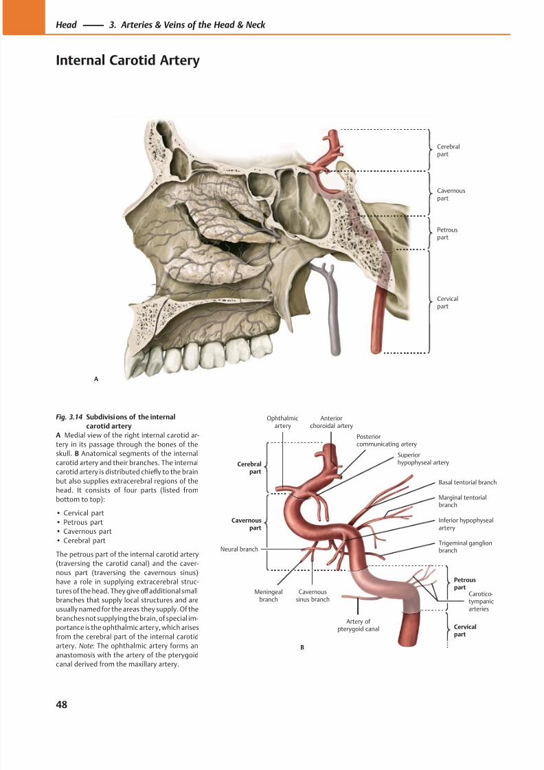
8/15/2019 Head and Neck Anatomy for Dental Medicine - Thieme; (January 26, 2010)
http://slidepdf.com/reader/full/head-and-neck-anatomy-for-dental-medicine-thieme-january-26-2010 61/384
Cerebralpart
Cervicalpart
Petrouspart
Cavernouspart
A
Petrouspart
Cerebralpart
Meningealbranch
Inferior hypophysealartery
Carotico-tympanicarteries
Artery of pterygoid canal
Trigeminal ganglionbranch
Marginal tentorialbranch
Basal tentorial branch
Neural branch
Cavernoussinus branch
Superiorhypophyseal artery
Posteriorcommunicating artery
B
Cervicalpart
Ophthalmicartery
Anteriorchoroidal artery
Fig. 3.14 Subdivisions of the internal
carotid artery
A Medial view of the right internal carotid ar-
tery in its passage through the bones of the
skull. B Anatomical segments of the internal
carotid artery and their branches. The internal
carotid artery is distributed chiefly to the brain
but also supplies extracerebral regions of the
head. It consists of four parts (listed from
bottom to top):
• Cervical part
• Petrous part
• Cavernous part
• Cerebral part
The petrous part of the internal carotid artery
(traversing the carotid canal) and the caver-
nous part (traversing the cavernous sinus)
have a role in supplying extracerebral struc-
tures of the head. They give off additional small
branches that supply local structures and are
usually named for the areas they supply. Of the
branches not supplying the brain, of special im-
portance is the ophthalmic artery, which arises
from the cerebral part of the internal carotid
artery. Note: The ophthalmic artery forms an
anastomosis with the artery of the pterygoid
canal derived from the maxillary artery.
48
Head 3. Arteries & Veins of the Head & Neck
Internal Carotid Artery
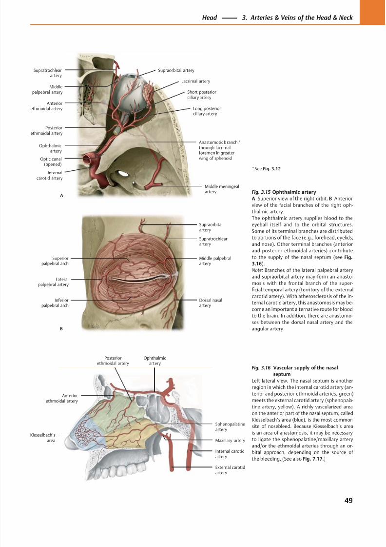
8/15/2019 Head and Neck Anatomy for Dental Medicine - Thieme; (January 26, 2010)
http://slidepdf.com/reader/full/head-and-neck-anatomy-for-dental-medicine-thieme-january-26-2010 62/384
Posteriorethmoidal artery
Ophthalmicartery
Internalcarotid artery
Middle meningeal
artery
Anastomotic branch,*through lacrimalforamen in greaterwing of sphenoidOptic canal
(opened)
Short posterior
ciliary artery
Lacrimal artery
Supraorbital artery
Middlepalpebral artery
Anteriorethmoidal artery
A
Long posteriorciliary artery
Supratrochlearartery
Lateralpalpebral artery
Inferiorpalpebral arch
Dorsal nasalartery
Middle palpebralartery
Supratrochlearartery
Supraorbitalartery
Superiorpalpebral arch
B
Kiesselbach’sarea
Sphenopalatineartery
Maxillary artery
External carotidartery
Internal carotidartery
Ophthalmicartery
Posteriorethmoidal artery
Anteriorethmoidal artery
Fig. 3.15 Ophthalmic arteryA Superior view of the right orbit. B Anterior
view of the facial branches of the right oph-
thalmic artery.
The ophthalmic artery supplies blood to the
eyeball itself and to the orbital structures.
Some of its terminal branches are distributed
to portions of the face (e.g., forehead, eyelids,
and nose). Other terminal branches (anterior
and posterior ethmoidal arteries) contribute
to the supply of the nasal septum (see Fig.
3.16).
Note: Branches of the lateral palpebral artery
and supraorbital artery may form an anasto-
mosis with the frontal branch of the super-
ficial temporal artery (territory of the external
carotid artery). With atherosclerosis of the in-
ternal carotid artery, this anastomosis may be-
come an important alternative route for blood
to the brain. In addition, there are anastomo-
ses between the dorsal nasal artery and the
angular artery.
Fig. 3.16 Vascular supply of the nasal
septum
Left lateral view. The nasal septum is anotherregion in which the internal carotid artery (an-
terior and posterior ethmoidal arteries, green)
meets the external carotid artery (sphenopala-
tine artery, yellow). A richly vascularized area
on the anterior part of the nasal septum, called
Kiesselbach’s area (blue), is the most common
site of nosebleed. Because Kiesselbach’s area
is an area of anastomosis, it may be necessary
to ligate the sphenopalatine/maxillary artery
and/or the ethmoidal arteries through an or-
bital approach, depending on the source of
the bleeding. (See also Fig. 7.17.)
* See Fig. 3.12
49
Head 3. Arteries & Veins of the Head & Neck
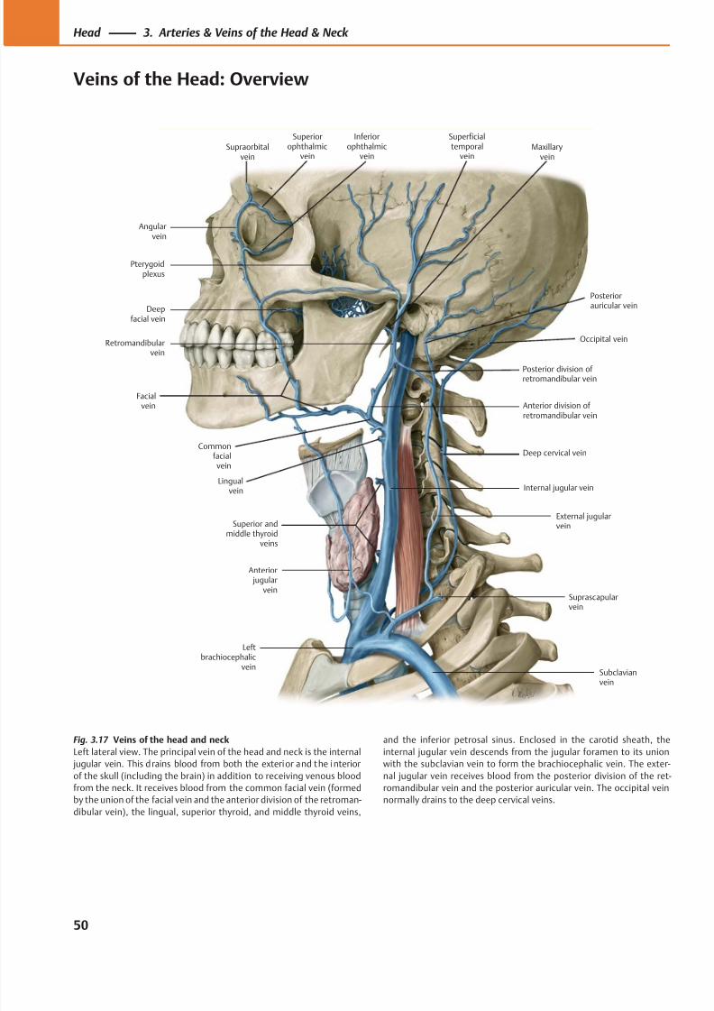
8/15/2019 Head and Neck Anatomy for Dental Medicine - Thieme; (January 26, 2010)
http://slidepdf.com/reader/full/head-and-neck-anatomy-for-dental-medicine-thieme-january-26-2010 63/384
Pterygoidplexus
Angularvein
Commonfacial vein
Facialvein
Anterior jugular
vein
Leftbrachiocephalic
veinSubclavianvein
Suprascapularvein
External jugularvein
Internal jugular vein
Deep cervical vein
Anterior division of retromandibular vein
Occipital vein
Posteriorauricular vein
Supraorbitalvein
Superiorophthalmic
vein
Inferiorophthalmic
vein
Superficialtemporal
veinMaxillary
vein
Deepfacial vein
Retromandibular
vein
Lingual vein
Superior and
middle thyroidveins
Posterior division of retromandibular vein
Fig. 3.17 Veins of the head and neck
Left lateral view. The principal vein of the head and neck is the internal
jugular vein. This drains blood from both the exterior and the interior
of the skull (including the brain) in addition to receiving venous blood
from the neck. It receives blood from the common facial vein (formed
by the union of the facial vein and the anterior division of the retroman-
dibular vein), the lingual, superior thyroid, and middle thyroid veins,
and the inferior petrosal sinus. Enclosed in the carotid sheath, the
internal jugular vein descends from the jugular foramen to its union
with the subclavian vein to form the brachiocephalic vein. The exter-
nal jugular vein receives blood from the posterior division of the ret-
romandibular vein and the posterior auricular vein. The occipital vein
normally drains to the deep cervical veins.
50
Head 3. Arteries & Veins of the Head & Neck
Veins of the Head: Overview
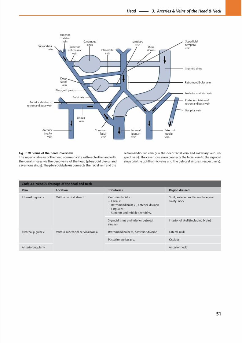
8/15/2019 Head and Neck Anatomy for Dental Medicine - Thieme; (January 26, 2010)
http://slidepdf.com/reader/full/head-and-neck-anatomy-for-dental-medicine-thieme-january-26-2010 64/384
Maxillaryvein
Duralsinuses
Superficialtemporalvein
Sigmoid sinus
Retromandibular vein
Posterior auricular vein
Posterior division of retromandibular vein
Occipital vein
Infraorbitalvein
Cavernoussinus
Superiorophthalmic
vein
Superiortrochlear
vein
Extermal jugularvein
Internal jugularvein
Commonfacial
vein
Lingual
vein
Anterior jugular
vein
Anterior division of retromandibular vein
Facial vein
Pterygoid plexus
Deepfacial
vein
Supraorbitalvein
Table 3.5 Venous drainage of the head and neck
Vein Location Tributaries Region drained
Internal jugular v. Within carotid sheath Common facial v.
— Facial v.
— Retromandibular v., anterior division
— Lingual v.
— Superior and middle thyroid vv.
Skull, anterior and lateral face, oral
cavity, neck
Sigmoid sinus and inferior petrosal
sinuses
Interior of skull (including brain)
External jugular v. Within superficial cervical fascia Retromandibular v., posterior division Lateral skull
Posterior auricular v. Occiput
Anterior jugular v. Anterior neck
Fig. 3.18 Veins of the head: overview
The superficial veins of the head communicate with each other and with
the dural sinuses via the deep veins of the head (pterygoid plexus and
cavernous sinus). The pterygoid plexus connects the facial vein and the
retromandibular vein (via the deep facial vein and maxillary vein, re-
spectively). The cavernous sinus connects the facial vein to the sigmoid
sinus (via the ophthalmic veins and the petrosal sinuses, respectively).
51
Head 3. Arteries & Veins of the Head & Neck
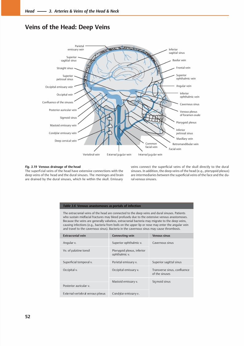
8/15/2019 Head and Neck Anatomy for Dental Medicine - Thieme; (January 26, 2010)
http://slidepdf.com/reader/full/head-and-neck-anatomy-for-dental-medicine-thieme-january-26-2010 65/384
Frontal vein
Superiorophthalmic vein
Inferiorophthalmic vein
Angular vein
Venous plexusof foramen ovale
Pterygoid plexus
Inferiorpetrosal sinus
Facial vein
External jugular vein Internal jugular veinVertebral vein
Deep cervical vein
Condylar emissary vein
Sigmoid sinus
Mastoid emissary vein
Posterior auricular vein
Occipital vein
Confluence of the sinuses
Occipital emissary vein
Straight sinus
Superior
sagittal sinus
Parietalemissary vein Inferior
sagittal sinus
Superiorpetrosal sinus
Basilar vein
Cavernous sinus
Retromandibular vein
Maxillary vein
Commonfacial vein
Table 3.6 Venous anastomoses as portals of infection
The extracranial veins of the head are connected to the deep veins and dural sinuses. Patients
who sustain midfacial fractures may bleed profusely due to the extensive venous anastomoses.
Because the veins are generally valveless, extracranial bacteria may migrate to the deep veins,
causing infections (e.g., bacteria from boils on the upper lip or nose may enter the angular vein
and travel to the cavernous sinus). Bacteria in the cavernous sinus may cause thrombosis.
Extracranial vein Connecting vein Venous sinus
Angular v. Superior ophthalmic v. Cavernous sinus
Vv. of palatine tonsil Pterygoid plexus, inferior
ophthalmic v.
Superficial temporal v. Parietal emissary v. Superior sagittal sinus
Occipital v. Occipital emissary v. Transverse sinus, confluence
of the sinuses
Mastoid emissary v. Sigmoid sinus
Posterior auricular v.
External vertebral venous plexus Condylar emissary v.
Fig. 3.19 Venous drainage of the head
The superficial veins of the head have extensive connections with the
deep veins of the head and the dural sinuses. The meninges and brain
are drained by the dural sinuses, which lie within the skull. Emissary
veins connect the superficial veins of the skull directly to the dural
sinuses. In addition, the deep veins of the head (e.g., pterygoid plexus)
are intermediaries between the superficial veins of the face and the du-
ral venous sinuses.
52
Head 3. Arteries & Veins of the Head & Neck
Veins of the Head: Deep Veins
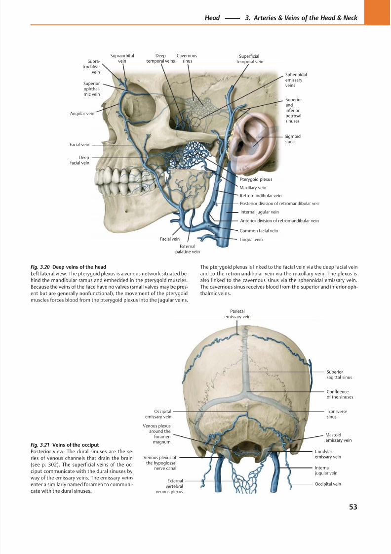
8/15/2019 Head and Neck Anatomy for Dental Medicine - Thieme; (January 26, 2010)
http://slidepdf.com/reader/full/head-and-neck-anatomy-for-dental-medicine-thieme-january-26-2010 66/384
External
vertebralvenous plexus
Venous plexus of the hypoglossal
nerve canal
Venous plexusaround the
foramenmagnum
Transversesinus
Confluenceof the sinuses
Superiorsagittal sinus
Parietalemissary vein
Occipitalemissary vein
Internal jugular vein
Mastoidemissary vein
Condylaremissary vein
Occipital vein
Superiorophthal-mic vein
Angular vein
Deepfacial vein
Externalpalatine vein
Facial vein
Internal jugular vein
Retromandibular vein
Pterygoid plexus
Deeptemporal veins
Maxillary vein
Cavernoussinus
Sigmoidsinus
Superiorandinferiorpetrosalsinuses
Superficialtemporal vein
Sphenoidalemissaryveins
Supra-trochlear
vein
Supraorbitalvein
Facial vein
Posterior division of retromandibular vein
Anterior division of retromandibular vein
Common facial vein
Lingual vein
Fig. 3.21 Veins of the occiput
Posterior view. The dural sinuses are the se-
ries of venous channels that drain the brain
(see p. 302). The superficial veins of the oc-
ciput communicate with the dural sinuses by
way of the emissary veins. The emissary veins
enter a similarly named foramen to communi-cate with the dural sinuses.
Fig. 3.20 Deep veins of the head
Left lateral view. The pterygoid plexus is a venous network situated be -
hind the mandibular ramus and embedded in the pterygoid muscles.
Because the veins of the face have no valves (small valves may be pres-
ent but are generally nonfunctional), the movement of the pterygoid
muscles forces blood from the pterygoid plexus into the jugular veins.
The pterygoid plexus is linked to the facial vein via the deep facial vein
and to the retromandibular vein via the maxillary vein. The plexus is
also linked to the cavernous sinus via the sphenoidal emissary vein.
The cavernous sinus receives blood from the superior and inferior oph-
thalmic veins.
53
Head 3. Arteries & Veins of the Head & Neck
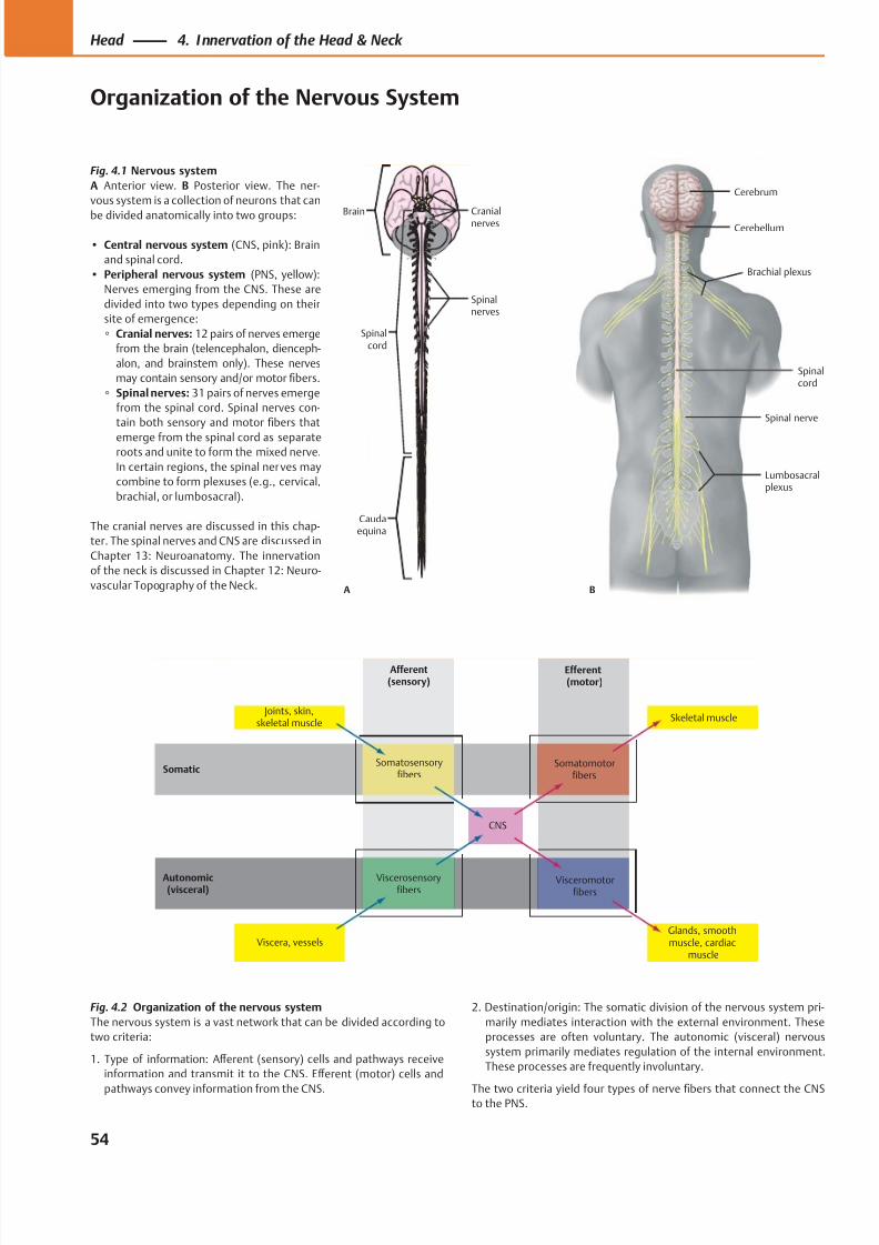
8/15/2019 Head and Neck Anatomy for Dental Medicine - Thieme; (January 26, 2010)
http://slidepdf.com/reader/full/head-and-neck-anatomy-for-dental-medicine-thieme-january-26-2010 67/384
Efferent(motor)
Afferent(sensory)
Visceromotorfibers
Viscerosensoryfibers
Viscera, vessels
Joints, skin,skeletal muscle
Somatosensoryfibers
Somatomotorfibers
Skeletal muscle
CNS
Glands, smoothmuscle, cardiac
muscle
Somatic
Autonomic(visceral)
Brain
Spinalcord
Caudaequina
Cranialnerves
Spinalnerves
A B
Lumbosacralplexus
Brachial plexus
Spinal nerve
Spinalcord
Cerebellum
Cerebrum
Fig. 4.2 Organization of the nervous system
The nervous system is a vast network that can be divided according to
two criteria:
1. Type of information: Aff erent (sensory) cells and pathways receive
information and transmit it to the CNS. Eff erent (motor) cells and
pathways convey information from the CNS.
Fig. 4.1 Nervous system
A Anterior view. B Posterior view. The ner-
vous system is a collection of neurons that can
be divided anatomically into two groups:
• Central nervous system (CNS, pink): Brain
and spinal cord.
• Peripheral nervous system (PNS, yellow):
Nerves emerging from the CNS. These are
divided into two types depending on their
site of emergence:
◦ Cranial nerves: 12 pairs of nerves emerge
from the brain (telencephalon, dienceph-
alon, and brainstem only). These nerves
may contain sensory and/or motor fibers.
◦ Spinal nerves: 31 pairs of nerves emerge
from the spinal cord. Spinal nerves con-
tain both sensory and motor fibers that
emerge from the spinal cord as separateroots and unite to form the mixed nerve.
In certain regions, the spinal nerves may
combine to form plexuses (e.g., cervical,
brachial, or lumbosacral).
The cranial nerves are discussed in this chap-
ter. The spinal nerves and CNS are discussed in
Chapter 13: Neuroanatomy. The innervation
of the neck is discussed in Chapter 12: Neuro-
vascular Topography of the Neck.
2. Destination/origin: The somatic division of the nervous system pri-
marily mediates interaction with the external environment. These
processes are often voluntary. The autonomic (visceral) nervous
system primarily mediates regulation of the internal environment.
These processes are frequently involuntary.
The two criteria yield four types of nerve fibers that connect the CNSto the PNS.
54
Head 4. Innervation of the Head & Neck
Organization of the Nervous System
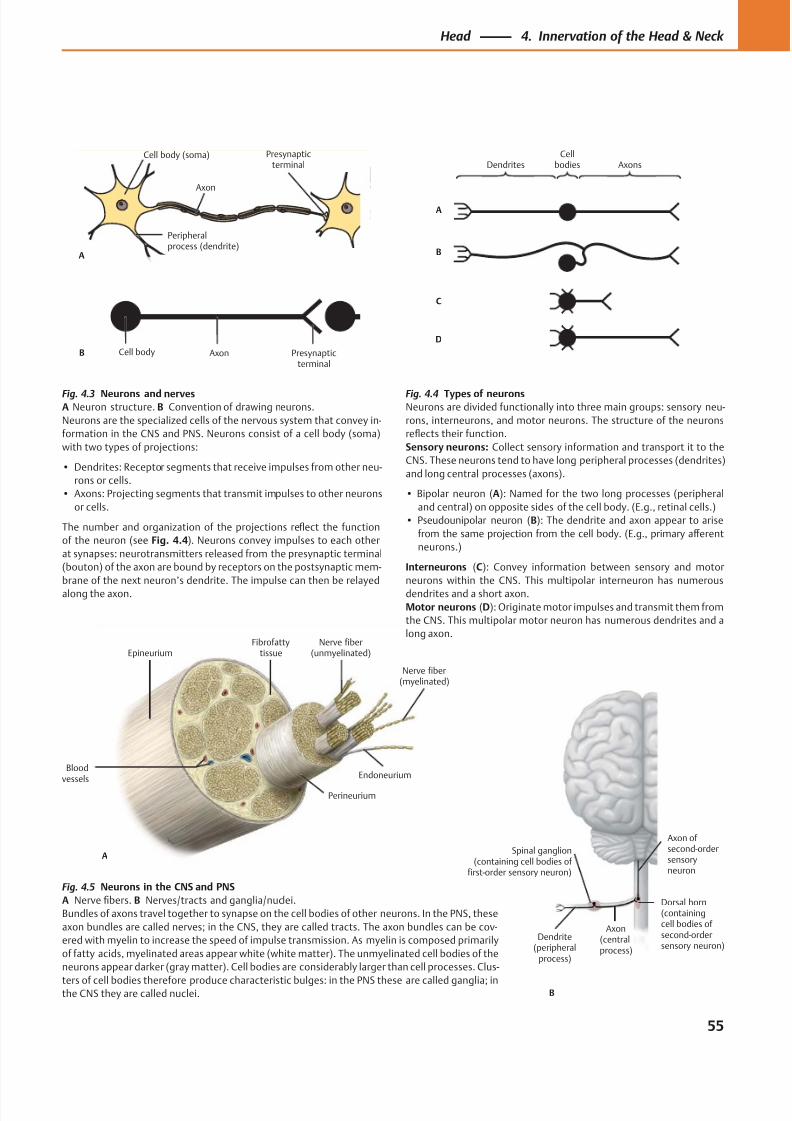
8/15/2019 Head and Neck Anatomy for Dental Medicine - Thieme; (January 26, 2010)
http://slidepdf.com/reader/full/head-and-neck-anatomy-for-dental-medicine-thieme-january-26-2010 68/384
A
Axon
Cell body (soma)
Peripheralprocess (dendrite)
Presynapticterminal
Cell body Axon Presynapticterminal
B
A
B
C
D
DendritesCell
bodies Axons
Bloodvessels
Epineurium
Perineurium
Endoneurium
Nerve fiber(myelinated)
Nerve fiber(unmyelinated)
Fibrofattytissue
A
B
Axon ofsecond-ordersensoryneuron
Dorsal horn(containingcell bodies of second-ordersensory neuron)
Dendrite(peripheral
process)
Spinal ganglion(containing cell bodies of
first-order sensory neuron)
Axon(centralprocess)
Fig. 4.3 Neurons and nervesA Neuron structure. B Convention of drawing neurons.
Neurons are the specialized cells of the nervous system that convey in-
formation in the CNS and PNS. Neurons consist of a cell body (soma)
with two types of projections:
• Dendrites: Receptor segments that receive impulses from other neu-
rons or cells.
• Axons: Projecting segments that transmit impulses to other neurons
or cells.
The number and organization of the projections reflect the function
of the neuron (see Fig. 4.4). Neurons convey impulses to each other
at synapses: neurotransmitters released from the presynaptic terminal
(bouton) of the axon are bound by receptors on the postsynaptic mem-
brane of the next neuron’s dendrite. The impulse can then be relayed
along the axon.
Fig. 4.5 Neurons in the CNS and PNS
A Nerve fibers. B Nerves/tracts and ganglia/nuclei.
Bundles of axons travel together to synapse on the cell bodies of other neurons. In the PNS, these
axon bundles are called nerves; in the CNS, they are called tracts. The axon bundles can be cov-
ered with myelin to increase the speed of impulse transmission. As myelin is composed primarily
of fatty acids, myelinated areas appear white (white matter). The unmyelinated cell bodies of the
neurons appear darker (gray matter). Cell bodies are considerably larger than cell processes. Clus-
ters of cell bodies therefore produce characteristic bulges: in the PNS these are called ganglia; inthe CNS they are called nuclei.
Fig. 4.4 Types of neuronsNeurons are divided functionally into three main groups: sensory neu-
rons, interneurons, and motor neurons. The structure of the neurons
reflects their function.
Sensory neurons: Collect sensory information and transport it to the
CNS. These neurons tend to have long peripheral processes (dendrites)
and long central processes (axons).
• Bipolar neuron (A): Named for the two long processes (peripheral
and central) on opposite sides of the cell body. (E.g., retinal cells.)
• Pseudounipolar neuron (B): The dendrite and axon appear to arise
from the same projection from the cell body. (E.g., primary aff erent
neurons.)
Interneurons (C): Convey information between sensory and motor
neurons within the CNS. This multipolar interneuron has numerous
dendrites and a short axon.
Motor neurons (D): Originate motor impulses and transmit them from
the CNS. This multipolar motor neuron has numerous dendrites and a
long axon.
55
Head 4. Innervation of the Head & Neck
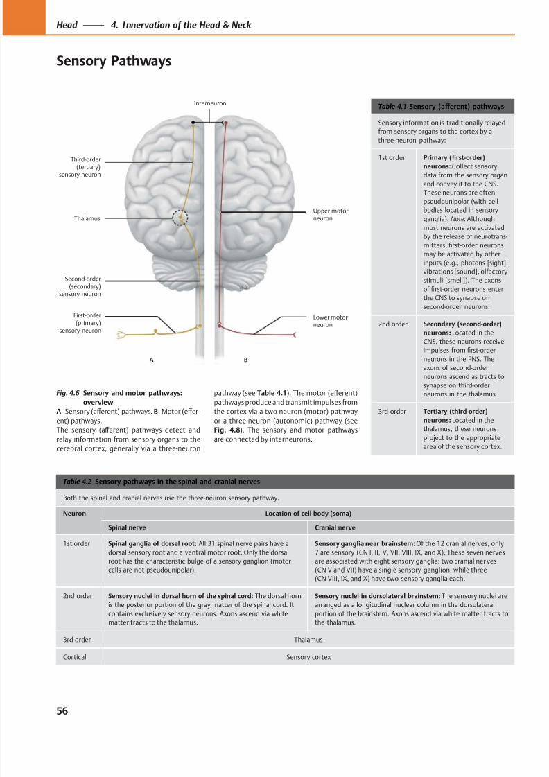
8/15/2019 Head and Neck Anatomy for Dental Medicine - Thieme; (January 26, 2010)
http://slidepdf.com/reader/full/head-and-neck-anatomy-for-dental-medicine-thieme-january-26-2010 69/384
Upper motorneuron
Lower motorneuron
Third-order(tertiary)
sensory neuron
A B
Interneuron
Thalamus
Second-order(secondary)
sensory neuron
First-order(primary)
sensory neuron
Table 4.1 Sensory (aff erent) pathways
Sensory information is traditionally relayed
from sensory organs to the cortex by a
three-neuron pathway:
1st order Primary (first-order)
neurons: Collect sensory
data from the sensory organ
and convey it to the CNS.
These neurons are often
pseudounipolar (with cell
bodies located in sensory
ganglia). Note: Although
most neurons are activated
by the release of neurotrans-
mitters, first-order neurons
may be activated by other
inputs (e.g., photons [sight],
vibrations [sound], olfactorystimuli [smell]). The axons
of first-order neurons enter
the CNS to synapse on
second-order neurons.
2nd order Secondary (second-order)
neurons: Located in the
CNS, these neurons receive
impulses from first-order
neurons in the PNS. The
axons of second-order
neurons ascend as tracts to
synapse on third-order
neurons in the thalamus.
3rd order Tertiary (third-order)
neurons: Located in the
thalamus, these neurons
project to the appropriate
area of the sensory cortex.
Table 4.2 Sensory pathways in the spinal and cranial nerves
Both the spinal and cranial nerves use the three-neuron sensory pathway.
Neuron Location of cell body (soma)
Spinal nerve Cranial nerve
1st order Spinal ganglia of dorsal root: All 31 spinal nerve pairs have adorsal sensory root and a ventral motor root. Only the dorsal
root has the characteristic bulge of a sensory ganglion (motor
cells are not pseudounipolar).
Sensory ganglia near brainstem: Of the 12 cranial nerves, only7 are sensory (CN I, II, V, VII, VIII, IX, and X). These seven nerves
are associated with eight sensory ganglia; two cranial ner ves
(CN V and VII) have a single sensory ganglion, while three
(CN VIII, IX, and X) have two sensory ganglia each.
2nd order Sensory nuclei in dorsal horn of the spinal cord: The dorsal horn
is the posterior portion of the gray matter of the spinal cord. It
contains exclusively sensory neurons. Axons ascend via white
matter tracts to the thalamus.
Sensory nuclei in dorsolateral brainstem: The sensory nuclei are
arranged as a longitudinal nuclear column in the dorsolateral
portion of the brainstem. Axons ascend via white matter tracts to
the thalamus.
3rd order Thalamus
Cortical Sensory cortex
Fig. 4.6 Sensory and motor pathways:
overview
A Sensory (aff erent) pathways. B Motor (eff er-
ent) pathways.
The sensory (aff erent) pathways detect and
relay information from sensory organs to the
cerebral cortex, generally via a three-neuron
pathway (see Table 4.1). The motor (eff erent)
pathways produce and transmit impulses from
the cortex via a two-neuron (motor) pathway
or a three-neuron (autonomic) pathway (see
Fig. 4.8). The sensory and motor pathways
are connected by interneurons.
56
Head 4. Innervation of the Head & Neck
Sensory Pathways
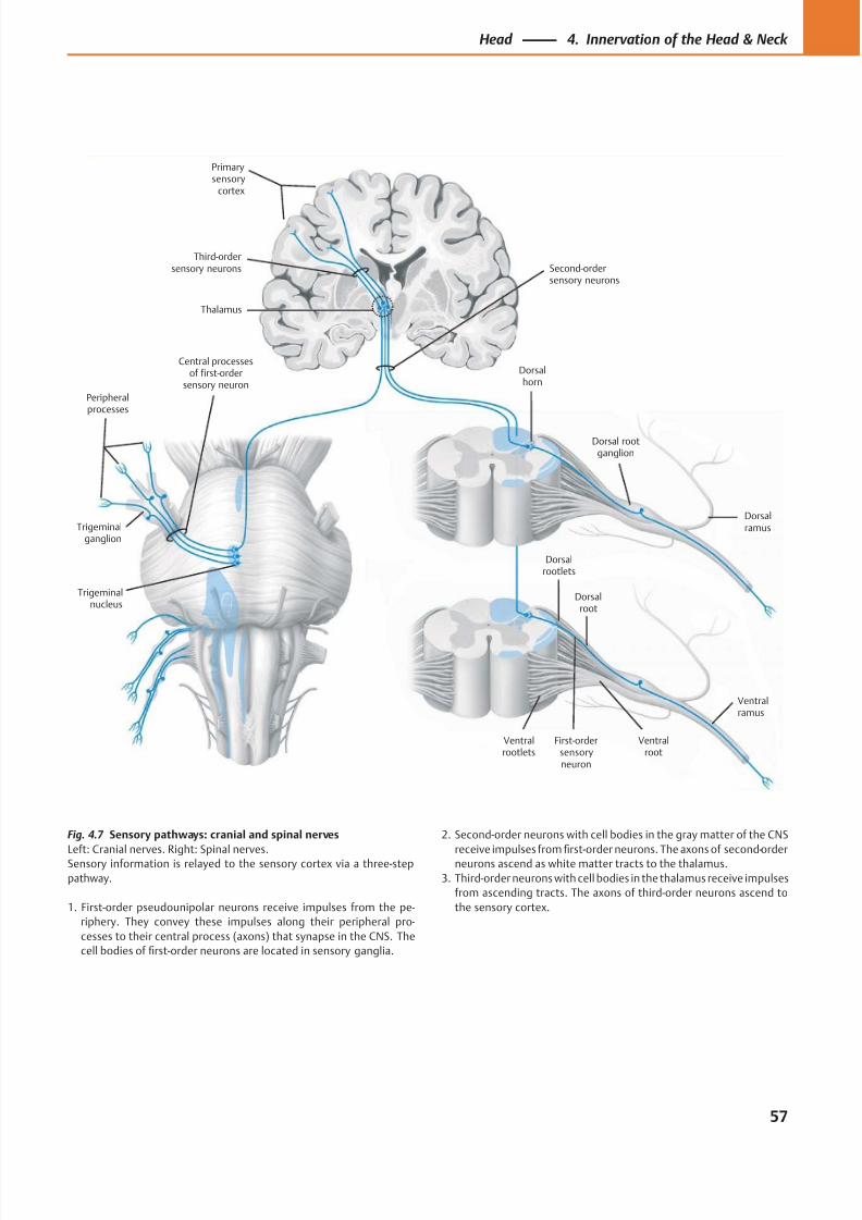
8/15/2019 Head and Neck Anatomy for Dental Medicine - Thieme; (January 26, 2010)
http://slidepdf.com/reader/full/head-and-neck-anatomy-for-dental-medicine-thieme-january-26-2010 70/384
Third-ordersensory neurons
Primarysensory
cortex
Thalamus
Peripheralprocesses
Trigeminalganglion
Ventralrootlets
Central processesof first-order
sensory neuron
Trigeminalnucleus
First-ordersensoryneuron
Ventralroot
Ventralramus
Dorsalroot
Dorsalrootlets
Dorsal rootganglion
Dorsalhorn
Second-ordersensory neurons
Dorsalramus
Fig. 4.7 Sensory pathways: cranial and spinal nerves
Left: Cranial nerves. Right: Spinal nerves.Sensory information is relayed to the sensory cortex via a three-step
pathway.
1. First-order pseudounipolar neurons receive impulses from the pe-
riphery. They convey these impulses along their peripheral pro-
cesses to their central process (axons) that synapse in the CNS. The
cell bodies of first-order neurons are located in sensory ganglia.
2. Second-order neurons with cell bodies in the gray matter of the CNS
receive impulses fromfi
rst-order neurons. The axons of second-orderneurons ascend as white matter tracts to the thalamus.
3. Third-order neurons with cell bodies in the thalamus receive impulses
from ascending tracts. The axons of third-order neurons ascend to
the sensory cortex.
57
Head 4. Innervation of the Head & Neck
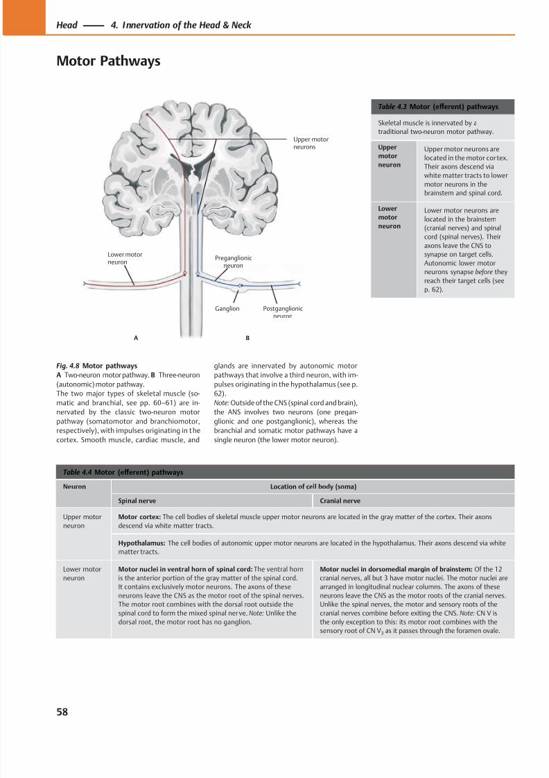
8/15/2019 Head and Neck Anatomy for Dental Medicine - Thieme; (January 26, 2010)
http://slidepdf.com/reader/full/head-and-neck-anatomy-for-dental-medicine-thieme-january-26-2010 71/384
Ganglion
Preganglionicneuron
Upper motorneurons
Postganglionicneuron
Lower motorneuron
A B
Table 4.3 Motor (eff erent) pathways
Skeletal muscle is innervated by a
traditional two-neuron motor pathway.
Upper
motor
neuron
Upper motor neurons are
located in the motor cor tex.
Their axons descend via
white matter tracts to lower
motor neurons in the
brainstem and spinal cord.
Lower
motor
neuron
Lower motor neurons are
located in the brainstem
(cranial nerves) and spinal
cord (spinal nerves). Their
axons leave the CNS to
synapse on target cells.
Autonomic lower motor
neurons synapse before theyreach their target cells (see
p. 62).
Table 4.4 Motor (eff erent) pathways
Neuron Location of cell body (soma)
Spinal nerve Cranial nerve
Upper motor
neuron
Motor cortex: The cell bodies of skeletal muscle upper motor neurons are located in the gray matter of the cortex. Their axons
descend via white matter tracts.
Hypothalamus: The cell bodies of autonomic upper motor neurons are located in the hypothalamus. Their axons descend via whitematter tracts.
Lower motor
neuron
Motor nuclei in ventral horn of spinal cord: The ventral horn
is the anterior portion of the gray matter of the spinal cord.
It contains exclusively motor neurons. The axons of these
neurons leave the CNS as the motor root of the spinal nerves.
The motor root combines with the dorsal root outside the
spinal cord to form the mixed spinal ner ve. Note: Unlike the
dorsal root, the motor root has no ganglion.
Motor nuclei in dorsomedial margin of brainstem: Of the 12
cranial nerves, all but 3 have motor nuclei. The motor nuclei are
arranged in longitudinal nuclear columns. The axons of these
neurons leave the CNS as the motor roots of the cranial nerves.
Unlike the spinal nerves, the motor and sensory roots of the
cranial nerves combine before exiting the CNS. Note: CN V is
the only exception to this: its motor root combines with the
sensory root of CN V3 as it passes through the foramen ovale.
Fig. 4.8 Motor pathways
A Two-neuron motor pathway. B Three-neuron
(autonomic) motor pathway.
The two major types of skeletal muscle (so-
matic and branchial, see pp. 60–61) are in-
nervated by the classic two-neuron motor
pathway (somatomotor and branchiomotor,
respectively), with impulses originating in the
cortex. Smooth muscle, cardiac muscle, and
glands are innervated by autonomic motor
pathways that involve a third neuron, with im-
pulses originating in the hypothalamus (see p.
62).
Note: Outside of the CNS (spinal cord and brain),
the ANS involves two neurons (one pregan-
glionic and one postganglionic), whereas the
branchial and somatic motor pathways have a
single neuron (the lower motor neuron).
58
Head 4. Innervation of the Head & Neck
Motor Pathways
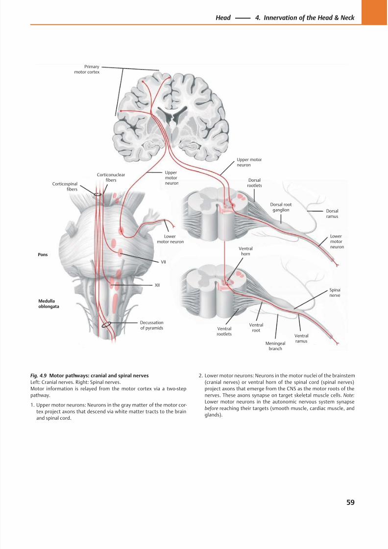
8/15/2019 Head and Neck Anatomy for Dental Medicine - Thieme; (January 26, 2010)
http://slidepdf.com/reader/full/head-and-neck-anatomy-for-dental-medicine-thieme-january-26-2010 72/384
Primarymotor cortex
Medullaoblongata
Corticospinalfibers
Ventralrootlets
Pons
XII
Ventralroot
Ventralramus
Decussationof pyramids
Dorsalrootlets
Dorsal rootganglion
Ventralhorn
VII
Dorsalramus
Meningealbranch
Spinalnerve
Upper motorneuron
Uppermotorneuron
Lowermotor neuron
Lowermotorneuron
Corticonuclearfibers
Fig. 4.9 Motor pathways: cranial and spinal nerves
Left: Cranial nerves. Right: Spinal nerves.Motor information is relayed from the motor cortex via a two-step
pathway.
1. Upper motor neurons: Neurons in the gray matter of the motor cor-
tex project axons that descend via white matter tracts to the brain
and spinal cord.
2. Lower motor neurons: Neurons in the motor nuclei of the brainstem
(cranial nerves) or ventral horn of the spinal cord (spinal nerves)project axons that emerge from the CNS as the motor roots of the
nerves. These axons synapse on target skeletal muscle cells. Note:
Lower motor neurons in the autonomic nervous system synapse
before reaching their targets (smooth muscle, cardiac muscle, and
glands).
59
Head 4. Innervation of the Head & Neck
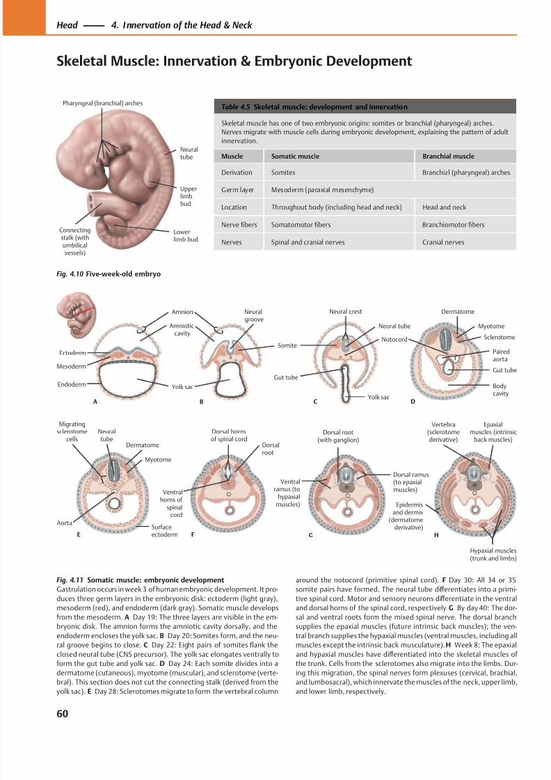
8/15/2019 Head and Neck Anatomy for Dental Medicine - Thieme; (January 26, 2010)
http://slidepdf.com/reader/full/head-and-neck-anatomy-for-dental-medicine-thieme-january-26-2010 73/384
Pharyngeal (branchial) arches
Upperlimbbud
Lowerlimb bud
Connectingstalk (withumbilicalvessels)
Neuraltube
Mesoderm
Endoderm
Ectoderm
A
Amnion
Amnioticcavity
Neuralgroove
Yolk sac
B
Somite
Neural crest
Neural tube
Yolk sac
Gut tube
C
Notocord
D
Dermatome
Myotome
Sclerotome
Pairedaorta
Gut tube
Bodycavity
ESurfaceectoderm
Myotome
Dermatome
Neuraltube
Migratingsclerotome
cells
Aorta
H
Vertebra(sclerotomederivative)
Epaxialmuscles (intrinsic
back muscles)
Hypaxial muscles(trunk and limbs)
Epidermisand dermis
(dermatomederivative)
F
Dorsalroot
Dorsal hornsof spinal cord
Ventralhorns of
spinalcord
G
Dorsal ramus(to epaxialmuscles)
Dorsal root(with ganglion)
Ventralramus (to
hypaxialmuscles)
Table 4.5 Skeletal muscle: development and innervation
Skeletal muscle has one of two embryonic origins: somites or branchial (pharyngeal) arches.
Nerves migrate with muscle cells during embryonic development, explaining the pattern of adult
innervation.
Muscle Somatic muscle Branchial muscle
Derivation Somites Branchial (pharyngeal) arches
Germ layer Mesoderm (paraxial mesenchyme)
Location Throughout body (including head and neck) Head and neck
Nerve fibers Somatomotor fibers Branchiomotor fibers
Nerves Spinal and cranial nerves Cranial nerves
Fig. 4.10 Five-week-old embryo
Fig. 4.11 Somatic muscle: embryonic development
Gastrulation occurs in week 3 of human embryonic development. It pro-
duces three germ layers in the embryonic disk: ectoderm (light gray),
mesoderm (red), and endoderm (dark gray). Somatic muscle develops
from the mesoderm. A Day 19: The three layers are visible in the em-
bryonic disk. The amnion forms the amniotic cavity dorsally, and the
endoderm encloses the yolk sac. B Day 20: Somites form, and the neu-
ral groove begins to close. C Day 22: Eight pairs of somites flank the
closed neural tube (CNS precursor). The yolk sac elongates ventrally to
form the gut tube and yolk sac. D Day 24: Each somite divides into a
dermatome (cutaneous), myotome (muscular), and sclerotome (verte-
bral). This section does not cut the connecting stalk (derived from theyolk sac). E Day 28: Sclerotomes migrate to form the vertebral column
around the notocord (primitive spinal cord). F Day 30: All 34 or 35
somite pairs have formed. The neural tube diff erentiates into a primi-
tive spinal cord. Motor and sensory neurons diff erentiate in the ventral
and dorsal horns of the spinal cord, respectively. G By day 40: The dor-
sal and ventral roots form the mixed spinal nerve. The dorsal branch
supplies the epaxial muscles (future intrinsic back muscles); the ven-
tral branch supplies the hypaxial muscles (ventral muscles, including all
muscles except the intrinsic back musculature). H Week 8: The epaxial
and hypaxial muscles have diff erentiated into the skeletal muscles of
the trunk. Cells from the sclerotomes also migrate into the limbs. Dur-
ing this migration, the spinal nerves form plexuses (cervical, brachial,
and lumbosacral), which innervate the muscles of the neck, upper limb,and lower limb, respectively.
60
Head 4. Innervation of the Head & Neck
Skeletal Muscle: Innervation & Embryonic Development
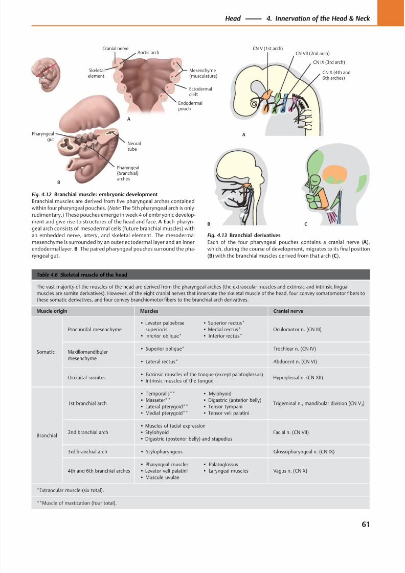
8/15/2019 Head and Neck Anatomy for Dental Medicine - Thieme; (January 26, 2010)
http://slidepdf.com/reader/full/head-and-neck-anatomy-for-dental-medicine-thieme-january-26-2010 74/384
CN V (1st arch)
A
B C
CN VII (2nd arch)
CN IX (3rd arch)
CN X (4th and6th arches)
Ectodermalcleft
Mesenchyme(musculature)
Aortic arch
Skeletalelement
Cranial nerve
Endodermalpouch
A
Pharyngealgut
Neuraltube
Pharyngeal(branchial)arches
B
Table 4.6 Skeletal muscle of the head
The vast majority of the muscles of the head are derived from the pharyngeal arches (the extraocular muscles and extrinsic and intrinsic lingual
muscles are somite derivatives). However, of the eight cranial nerves that innervate the skeletal muscle of the head, four convey somatomotor fibers to
these somatic derivatives, and four convey branchiomotor fibers to the branchial arch derivatives.
Muscle origin Muscles Cranial nerve
Somatic
Prochordal mesenchyme
• Levator palpebrae
superioris
• Inferior oblique*
• Superior rectus*
• Medial rectus*
• Inferior rectus*
Oculomotor n. (CN III)
Maxillomandibular
mesenchyme
• Superior oblique* Trochlear n. (CN IV)
• Lateral rectus* Abducent n. (CN VI)
Occipital somites• Extrinsic muscles of the tongue (except palatoglossus)
• Intrinsic muscles of the tongueHypoglossal n. (CN XII)
Branchial
1st branchial arch
• Temporalis**
• Masseter**• Lateral pterygoid**
• Medial pterygoid**
• Mylohyoid
• Digastric (anterior belly)• Tensor tympani
• Tensor veli palatini
Trigeminal n., mandibular division (CN V3)
2nd branchial arch
• Muscles of facial expression
• Stylohyoid
• Digastric (posterior belly) and stapedius
Facial n. (CN VII)
3rd branchial arch • Stylopharyngeus Glossopharyngeal n. (CN IX)
4th and 6th branchial arches
• Pharyngeal muscles
• Levator veli palatini
• Muscule uvulae
• Palatoglossus
• Laryngeal muscles Vagus n. (CN X)
*Extraocular muscle (six total).
**Muscle of mastication (four total).
Fig. 4.12 Branchial muscle: embryonic development
Branchial muscles are derived from five pharyngeal arches containedwithin four pharyngeal pouches. (Note: The 5th pharyngeal arch is only
rudimentary.) These pouches emerge in week 4 of embryonic develop-
ment and give rise to structures of the head and face. A Each pharyn-
geal arch consists of mesodermal cells (future branchial muscles) with
an embedded nerve, artery, and skeletal element. The mesodermal
mesenchyme is surrounded by an outer ec todermal layer and an inner
endodermal layer. B The paired pharyngeal pouches surround the pha-
ryngeal gut.
Fig. 4.13 Branchial derivatives
Each of the four pharyngeal pouches contains a cranial nerve (A),
which, during the course of development, migrates to its final position
(B) with the branchial muscles derived from that arch (C).
61
Head 4. Innervation of the Head & Neck
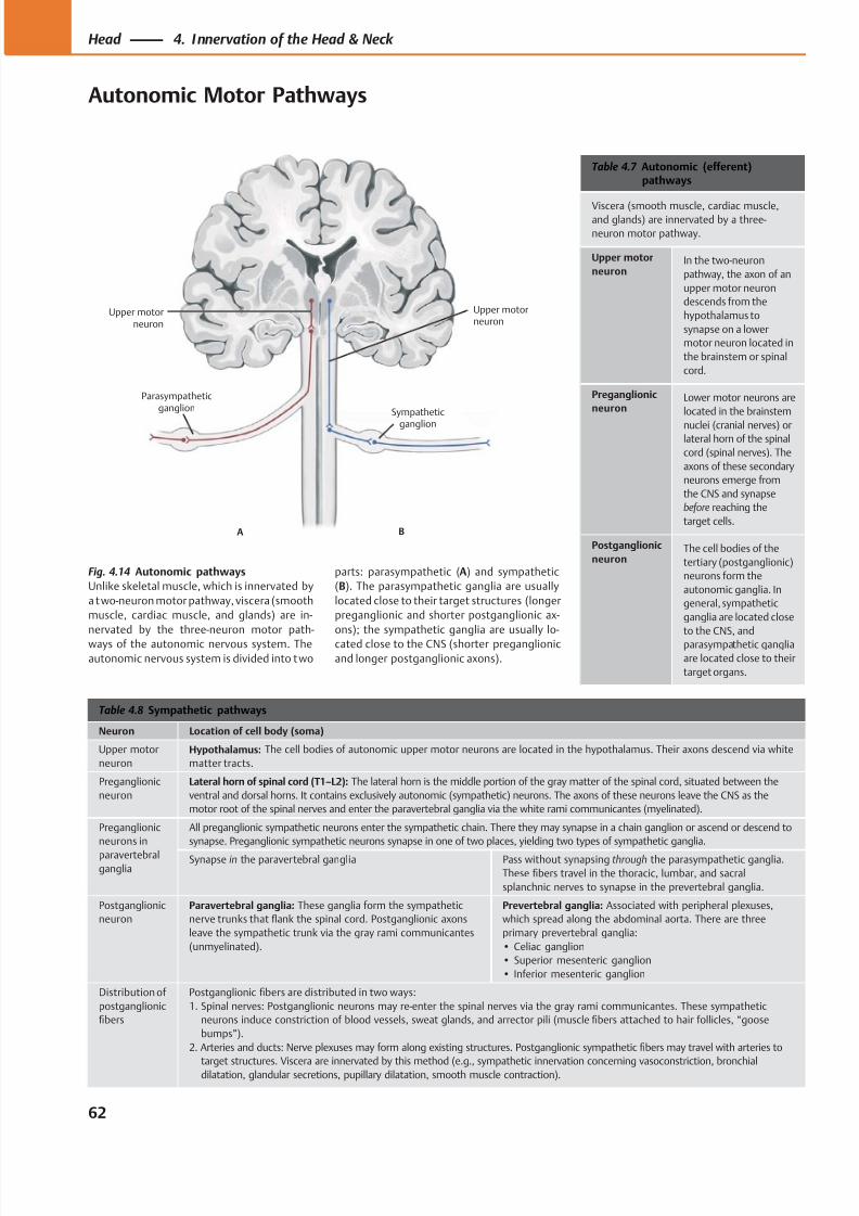
8/15/2019 Head and Neck Anatomy for Dental Medicine - Thieme; (January 26, 2010)
http://slidepdf.com/reader/full/head-and-neck-anatomy-for-dental-medicine-thieme-january-26-2010 75/384
Sympathetic
ganglion
Upper motorneuron
Upper motorneuron
Parasympatheticganglion
A B
Table 4.7 Autonomic (efferent)pathways
Viscera (smooth muscle, cardiac muscle,
and glands) are innervated by a three-
neuron motor pathway.
Upper motor
neuronIn the two-neuron
pathway, the axon of an
upper motor neuron
descends from the
hypothalamus to
synapse on a lower
motor neuron located in
the brainstem or spinal
cord.
Preganglionic
neuronLower motor neurons are
located in the brainstem
nuclei (cranial nerves) orlateral horn of the spinal
cord (spinal nerves). The
axons of these secondary
neurons emerge from
the CNS and synapse
before reaching the
target cells.
Postganglionic
neuronThe cell bodies of the
tertiary (postganglionic)
neurons form the
autonomic ganglia. In
general, sympathetic
ganglia are located close
to the CNS, and
parasympathetic ganglia
are located close to their
target organs.
Table 4.8 Sympathetic pathways
Neuron Location of cell body (soma)
Upper motor
neuron
Hypothalamus: The cell bodies of autonomic upper motor neurons are located in the hypothalamus. Their axons descend via white
matter tracts.
Preganglionic
neuron
Lateral horn of spinal cord (T1–L2): The lateral horn is the middle portion of the gray matter of the spinal cord, situated between the
ventral and dorsal horns. It contains exclusively autonomic (sympathetic) neurons. The axons of these neurons leave the CNS as the
motor root of the spinal nerves and enter the paravertebral ganglia via the white rami communicantes (myelinated).
Preganglionic
neurons in
paravertebralganglia
All preganglionic sympathetic neurons enter the sympathetic chain. There they may synapse in a chain ganglion or ascend or descend to
synapse. Preganglionic sympathetic neurons synapse in one of two places, yielding two types of sympathetic ganglia.
Synapse in the paravertebral ganglia Pass without synapsing through the parasympathetic ganglia.
These fibers travel in the thoracic, lumbar, and sacral
splanchnic nerves to synapse in the prevertebral ganglia.
Postganglionic
neuron
Paravertebral ganglia: These ganglia form the sympathetic
nerve trunks that flank the spinal cord. Postganglionic axons
leave the sympathetic trunk via the gray rami communicantes
(unmyelinated).
Prevertebral ganglia: Associated with peripheral plexuses,
which spread along the abdominal aorta. There are three
primary prevertebral ganglia:
• Celiac ganglion
• Superior mesenteric ganglion
• Inferior mesenteric ganglion
Distribution of
postganglionic
fibers
Postganglionic fibers are distributed in two ways:
1. Spinal nerves: Postganglionic neurons may re-enter the spinal nerves via the gray rami communicantes. These sympathetic
neurons induce constriction of blood vessels, sweat glands, and arrector pili (muscle fibers attached to hair follicles, “goose
bumps”).
2. Arteries and ducts: Nerve plexuses may form along existing structures. Postganglionic sympathetic fibers may travel with arteries to
target structures. Viscera are innervated by this method (e.g., sympathetic innervation concerning vasoconstriction, bronchialdilatation, glandular secretions, pupillary dilatation, smooth muscle contraction).
Fig. 4.14 Autonomic pathways
Unlike skeletal muscle, which is innervated by
a two-neuron motor pathway, viscera (smooth
muscle, cardiac muscle, and glands) are in-
nervated by the three-neuron motor path-
ways of the autonomic nervous system. The
autonomic nervous system is divided into two
parts: parasympathetic (A) and sympathetic
(B). The parasympathetic ganglia are usually
located close to their target structures (longer
preganglionic and shorter postganglionic ax-
ons); the sympathetic ganglia are usually lo-
cated close to the CNS (shorter preganglionic
and longer postganglionic axons).
62
Head 4. Innervation of the Head & Neck
Autonomic Motor Pathways
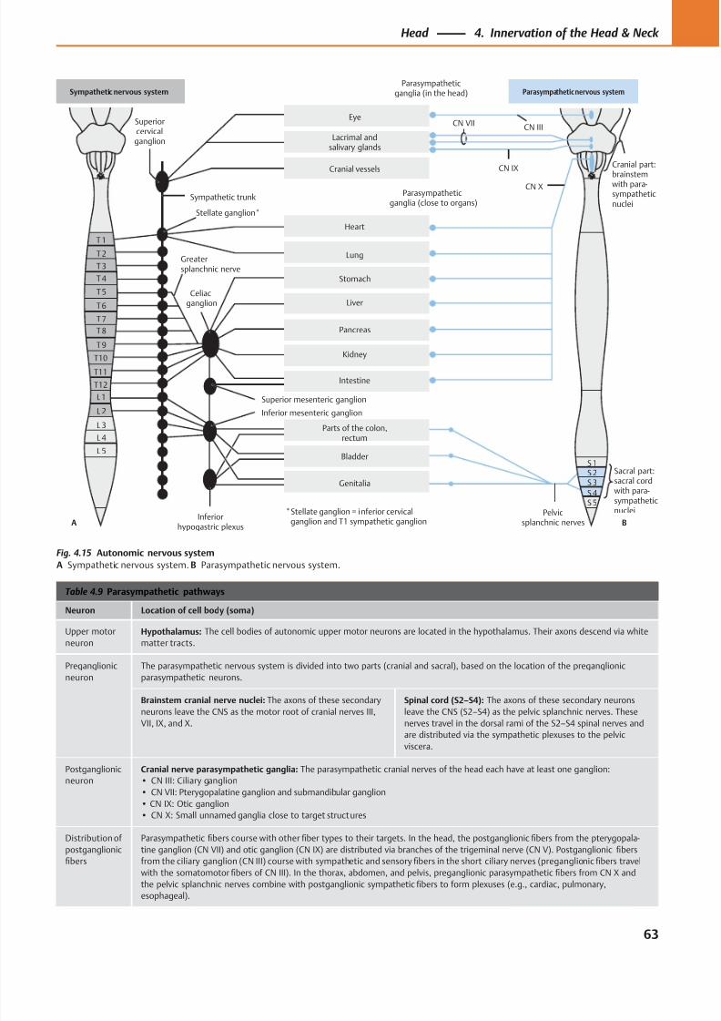
8/15/2019 Head and Neck Anatomy for Dental Medicine - Thieme; (January 26, 2010)
http://slidepdf.com/reader/full/head-and-neck-anatomy-for-dental-medicine-thieme-january-26-2010 76/384
T1
T2
T3
T4
T5
T6
T7
T8
T9
T10
T11
T12
L1
L 2
L 3
L 4
L 5
S 2
Superiorcervicalganglion
Sympathetic trunk
CN IIICN VII
CN IX
CN X
Cranial part:
brainstemwith para-sympatheticnuclei
Parasympatheticganglia (in the head)
Pelvicsplanchnic nerves
Parts of the colon,rectum
Stellate ganglion*
Superior mesenteric ganglion
Inferior mesenteric ganglion
Parasympatheticganglia (close to organs)
Genitalia
Bladder
S 5S 4
S 3
Celiacganglion
Greatersplanchnic nerve
Intestine
Kidney
Eye
Lacrimal andsalivary glands
Cranial vessels
Heart
Lung
Stomach
Liver
Pancreas
Sympathetic nervous system Parasympathetic nervous system
* Stellate ganglion = inferior cervical ganglion and T1 sympathetic ganglion
Sacral part:sacral cordwith para-sympatheticnuclei
Inferiorhypogastric plexus
A B
S 1
Table 4.9 Parasympathetic pathways
Neuron Location of cell body (soma)
Upper motor
neuron
Hypothalamus: The cell bodies of autonomic upper motor neurons are located in the hypothalamus. Their axons descend via white
matter tracts.
Preganglionic
neuron
The parasympathetic nervous system is divided into two parts (cranial and sacral), based on the location of the preganglionic
parasympathetic neurons.
Brainstem cranial nerve nuclei: The axons of these secondary
neurons leave the CNS as the motor root of cranial nerves III,VII, IX, and X.
Spinal cord (S2–S4): The axons of these secondary neurons
leave the CNS (S2–S4) as the pelvic splanchnic nerves. Thesenerves travel in the dorsal rami of the S2–S4 spinal nerves and
are distributed via the sympathetic plexuses to the pelvic
viscera.
Postganglionic
neuron
Cranial nerve parasympathetic ganglia: The parasympathetic cranial nerves of the head each have at least one ganglion:
• CN III: Ciliary ganglion
• CN VII: Pterygopalatine ganglion and submandibular ganglion
• CN IX: Otic ganglion
• CN X: Small unnamed ganglia close to target structures
Distribution of
postganglionic
fibers
Parasympathetic fibers course with other fiber types to their targets. In the head, the postganglionic fibers from the pterygopala-
tine ganglion (CN VII) and otic ganglion (CN IX) are distributed via branches of the trigeminal nerve (CN V). Postganglionic fibers
from the ciliary ganglion (CN III) course with sympathetic and sensory fibers in the short ciliary nerves (preganglionic fibers travel
with the somatomotor fibers of CN III). In the thorax, abdomen, and pelvis, preganglionic parasympathetic fibers from CN X and
the pelvic splanchnic nerves combine with postganglionic sympathetic fibers to form plexuses (e.g., cardiac, pulmonary,
esophageal).
Fig. 4.15 Autonomic nervous system
A Sympathetic nervous system. B Parasympathetic nervous system.
63
Head 4. Innervation of the Head & Neck
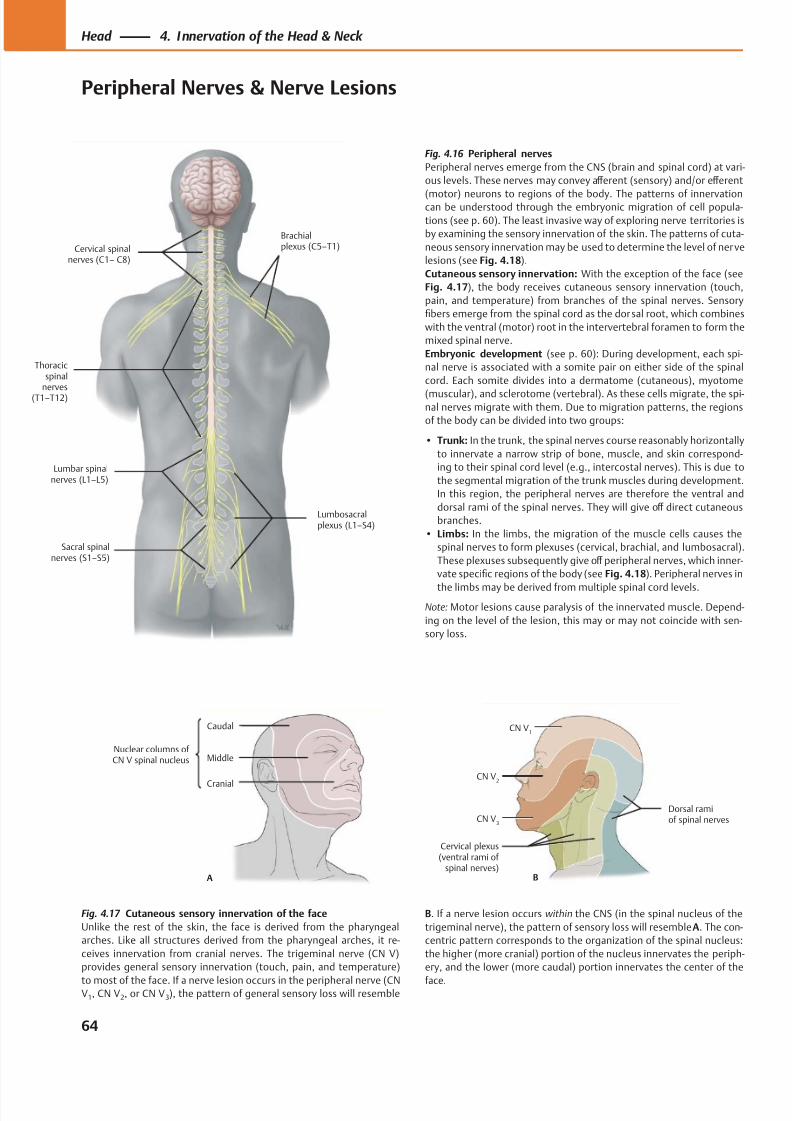
8/15/2019 Head and Neck Anatomy for Dental Medicine - Thieme; (January 26, 2010)
http://slidepdf.com/reader/full/head-and-neck-anatomy-for-dental-medicine-thieme-january-26-2010 77/384
Cervical spinalnerves (C1– C8)
Thoracicspinal
nervesT1–T12)
Lumbar spinalnerves (L1–L5)
Sacral spinalnerves (S1–S5)
Lumbosacralplexus (L1–S4)
Brachialplexus (C5–T1)
Middle
A
Caudal
Cranial
Nuclear columns of CN V spinal nucleus
CN V3
Cervical plexus(ventral rami of
spinal nerves)
Dorsal ramiof spinal nerves
CN V2
CN V1
B
Fig. 4.17 Cutaneous sensory innervation of the face
Unlike the rest of the skin, the face is derived from the pharyngeal
arches. Like all structures derived from the pharyngeal arches, it re-
ceives innervation from cranial nerves. The trigeminal nerve (CN V)
provides general sensory innervation (touch, pain, and temperature)
to most of the face. If a nerve lesion occurs in the peripheral nerve (CNV1, CN V2, or CN V3), the pattern of general sensory loss will resemble
Fig. 4.16 Peripheral nerves
Peripheral nerves emerge from the CNS (brain and spinal cord) at vari-
ous levels. These nerves may convey aff erent (sensory) and/or eff erent
(motor) neurons to regions of the body. The patterns of innervationcan be understood through the embryonic migration of cell popula-
tions (see p. 60). The least invasive way of exploring nerve territories is
by examining the sensory innervation of the skin. The patterns of cuta-
neous sensory innervation may be used to determine the level of nerve
lesions (see Fig. 4.18).
Cutaneous sensory innervation: With the exception of the face (see
Fig. 4.17), the body receives cutaneous sensory innervation (touch,
pain, and temperature) from branches of the spinal nerves. Sensory
fibers emerge from the spinal cord as the dorsal root, which combines
with the ventral (motor) root in the intervertebral foramen to form the
mixed spinal nerve.
Embryonic development (see p. 60): During development, each spi-
nal nerve is associated with a somite pair on either side of the spinal
cord. Each somite divides into a dermatome (cutaneous), myotome
(muscular), and sclerotome (vertebral). As these cells migrate, the spi-nal nerves migrate with them. Due to migration patterns, the regions
of the body can be divided into two groups:
• Trunk: In the trunk, the spinal nerves course reasonably horizontally
to innervate a narrow strip of bone, muscle, and skin correspond-
ing to their spinal cord level (e.g., intercostal nerves). This is due to
the segmental migration of the trunk muscles during development.
In this region, the peripheral nerves are therefore the ventral and
dorsal rami of the spinal nerves. They will give off direct cutaneous
branches.
• Limbs: In the limbs, the migration of the muscle cells causes the
spinal nerves to form plexuses (cervical, brachial, and lumbosacral).
These plexuses subsequently give off peripheral nerves, which inner-
vate specific regions of the body (see Fig. 4.18). Peripheral nerves in
the limbs may be derived from multiple spinal cord levels.
Note: Motor lesions cause paralysis of the innervated muscle. Depend-
ing on the level of the lesion, this may or may not coincide with sen-
sory loss.
B. If a nerve lesion occurs within the CNS (in the spinal nucleus of the
trigeminal nerve), the pattern of sensory loss will resemble A. The con-
centric pattern corresponds to the organization of the spinal nucleus:
the higher (more cranial) portion of the nucleus innervates the periph-
ery, and the lower (more caudal) portion innervates the center of the
face.
64
Head 4. Innervation of the Head & Neck
Peripheral Nerves & Nerve Lesions
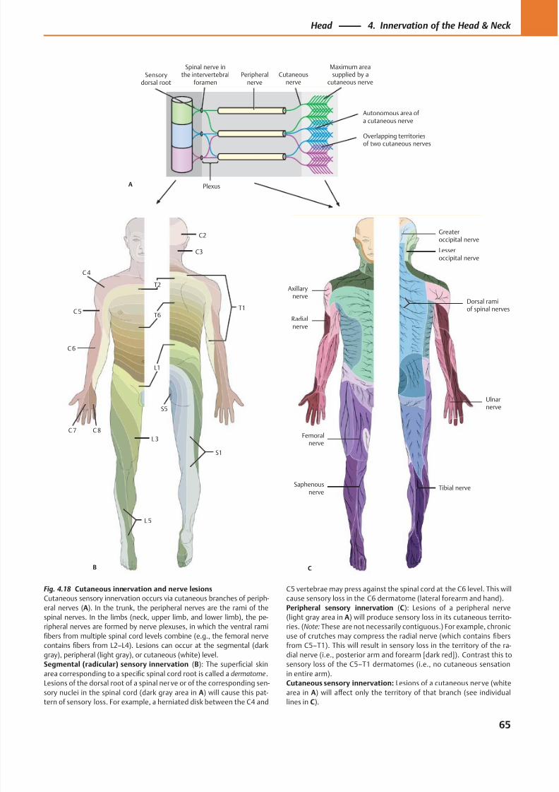
8/15/2019 Head and Neck Anatomy for Dental Medicine - Thieme; (January 26, 2010)
http://slidepdf.com/reader/full/head-and-neck-anatomy-for-dental-medicine-thieme-january-26-2010 78/384
C2
C3
C 4
T1
T2
T6C 5
C 6
C 8
L1
L3
L 5
S1
S5
C 7
B
Ulnarnerve
Axillarynerve
Dorsal ramiof spinal nerves
Greateroccipital nerve
Lesseroccipital nerve
Radialnerve
Femoralnerve
Saphenousnerve
Tibial nerve
C
Autonomous area of a cutaneous nerve
Maximum areasupplied by a
cutaneous nerveCutaneous
nervePeripheral
nerve
Plexus
Spinal nerve inthe intervertebral
foramenSensory
dorsal root
A
Overlapping territoriesof two cutaneous nerves
Fig. 4.18 Cutaneous innervation and nerve lesions
Cutaneous sensory innervation occurs via cutaneous branches of periph-
eral nerves (A). In the trunk, the peripheral nerves are the rami of the
spinal nerves. In the limbs (neck, upper limb, and lower limb), the pe-
ripheral nerves are formed by nerve plexuses, in which the ventral rami
fibers from multiple spinal cord levels combine (e.g., the femoral nerve
contains fibers from L2–L4). Lesions can occur at the segmental (dark
gray), peripheral (light gray), or cutaneous (white) level.
Segmental (radicular) sensory innervation (B): The superficial skin
area corresponding to a specific spinal cord root is called a dermatome.
Lesions of the dorsal root of a spinal nerve or of the corresponding sen-
sory nuclei in the spinal cord (dark gray area in A) will cause this pat-tern of sensory loss. For example, a herniated disk between the C4 and
C5 vertebrae may press against the spinal cord at the C6 level. This will
cause sensory loss in the C6 dermatome (lateral forearm and hand).
Peripheral sensory innervation (C): Lesions of a peripheral nerve
(light gray area in A) will produce sensory loss in its cutaneous territo-
ries. (Note: These are not necessarily contiguous.) For example, chronic
use of crutches may compress the radial nerve (which contains fibers
from C5–T1). This will result in sensory loss in the territory of the ra-
dial nerve (i.e., posterior arm and forearm [dark red]). Contrast this to
sensory loss of the C5–T1 dermatomes (i.e., no cutaneous sensation
in entire arm).
Cutaneous sensory innervation: Lesions of a cutaneous nerve (white
area in A) will aff ect only the territory of that branch (see individuallines in C).
65
Head 4. Innervation of the Head & Neck
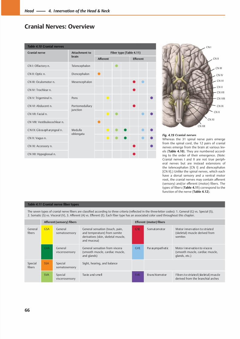
8/15/2019 Head and Neck Anatomy for Dental Medicine - Thieme; (January 26, 2010)
http://slidepdf.com/reader/full/head-and-neck-anatomy-for-dental-medicine-thieme-january-26-2010 79/384
CN III
CN XI
CN IX
CN VIII
CN V
CN VII
CN VI
CN IV
CN II
CN X
CN I
CN XII
Table 4.10 Cranial nerves
Cranial nerve Attachment to
brain
Fiber type (Table 4.11)
Aff erent Eff erent
CN I: Olfactory n. Telencephalon
CN II: Optic n. Diencephalon
CN III: Oculomotor n. Mesencephalon
CN IV: Trochlear n.
CN V: Trigeminal n. Pons
CN VI: Abducent n. Pontomedullary
junction
CN VII: Facial n.
CN VIII: Vestibulocochlear n.
CN IX: G lossopharyngeal n. Medulla
oblongata
CN X: Vagus n.
CN XI: Accessory n.
CN XII: Hypoglossal n.
Table 4.11 Cranial nerve fiber types
The seven types of cranial nerve fibers are classified according to three criteria (reflected in the three-letter codes): 1. General (G) vs. Special (S),
2. Somatic (S) vs. Visceral (V), 3. Aff erent (A) vs. Eff erent (E). Each fiber type has an associated color used throughout this chapter.
Aff erent (sensory) fibers Eff erent (motor) fibers
General
fibers
GSA General
somatosensory
General sensation (touch, pain,
and temperature) from somite
derivatives (skin, skeletal muscle,and mucosa)
GSE Somatomotor Motor innervation to striated
(skeletal) muscle derived from
somites
GVA General
viscerosensory
General sensation from viscera
(smooth muscle, cardiac muscle,
and glands)
GVE Parasympathet ic Motor innervat ion to viscera
(smooth muscle, cardiac muscle,
glands, etc.)
Special
fibers
SSA Special
somatosensory
Sight, hearing, and balance
SVA Special
viscerosensory
Taste and smell SVE Branchiomotor Fibers to striated (skeletal) muscle
derived from the branchial arches
Fig. 4.19 Cranial nerves
Whereas the 31 spinal nerve pairs emerge
from the spinal cord, the 12 pairs of cranial
nerves emerge from the brain at various lev-
els (Table 4.10). They are numbered accord-
ing to the order of their emergence. (Note:
Cranial nerves I and II are not true periph-
eral nerves but are instead extensions of
the telencephalon [CN I] and diencephalon
[CN II].) Unlike the spinal nerves, which each
have a dorsal sensory and a ventral motor
root, the cranial nerves may contain aff erent
(sensory) and/or eff erent (motor) fibers. The
types of fibers (Table 4.11) correspond to the
function of the nerve (Table 4.12).
66
Head 4. Innervation of the Head & Neck
Cranial Nerves: Overview
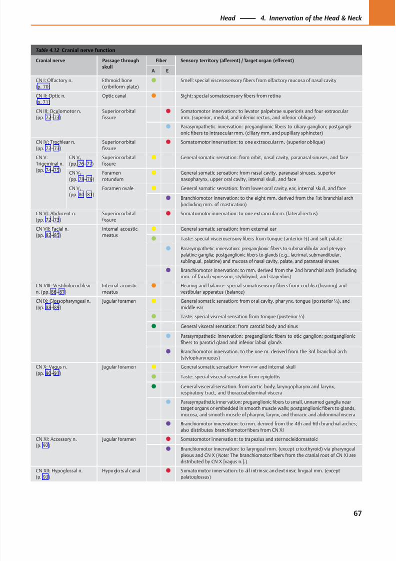
8/15/2019 Head and Neck Anatomy for Dental Medicine - Thieme; (January 26, 2010)
http://slidepdf.com/reader/full/head-and-neck-anatomy-for-dental-medicine-thieme-january-26-2010 80/384
Table 4.12 Cranial nerve function
Cranial nerve Passage through
skull
Fiber Sensory territory (aff erent) / Target organ (eff erent)
A E
CN I: Olfactory n.
(p. 70)
Ethmoid bone
(cribriform plate) Smell: special viscerosensory fibers from olfactory mucosa of nasal cavity
CN II: Optic n.(p. 71) Optic canal Sight: special somatosensoryfi
bers from retina
CN III: Oculomotor n.
(pp. 72–73)
Superior orbital
fissure
Somatomotor innervation: to levator palpebrae superioris and four extraocular
mm. (superior, medial, and inferior rectus, and inferior oblique)
Parasympathetic innervation: preganglionic fibers to ciliary ganglion; postgangli-
onic fibers to intraocular mm. (ciliary mm. and pupillary sphincter)
CN IV: Trochlear n.
(pp. 72–73)
Superior orbital
fissure
Somatomotor innervation: to one extraocular m. (superior oblique)
CN V:
Trigeminal n.
(pp. 74–75)
CN V1
(pp. 76–77)
Superior orbital
fissure
General somatic sensation: from orbit, nasal cavity, paranasal sinuses, and face
CN V2
(pp. 78–79)
Foramen
rotundum
General somatic sensation: from nasal cavity, paranasal sinuses, superior
nasopharynx, upper oral cavity, internal skull, and face
CN V3
(pp. 80–81)
Foramen ovale General somatic sensation: from lower oral cavit y, ear, internal skull, and face
Branchiomotor innervation: to the eight mm. derived from the 1st branchial arch(including mm. of mastication)
CN VI: Abducent n.
(pp. 72–73)
Superior orbital
fissure
Somatomotor innervation: to one extraocular m. (lateral rectus)
CN VII: Facial n.
(pp. 82–85)
Internal acoustic
meatus
General somatic sensation: from external ear
Taste: special viscerosensory fibers from tongue (anterior ⅔) and soft palate
Parasympathetic innervation: preganglionic fibers to submandibular and pterygo-
palatine ganglia; postganglionic fibers to glands (e.g., lacrimal, submandibular,
sublingual, palatine) and mucosa of nasal cavity, palate, and paranasal sinuses
Branchiomotor innervation: to mm. derived from the 2nd branchial arch (including
mm. of facial expression, stylohyoid, and stapedius)
CN VIII: Vestibulocochlear
n. (pp. 86–87)
Internal acoustic
meatus
Hearing and balance: special somatosensory fibers from cochlea (hearing) and
vestibular apparatus (balance)CN IX: Glossopharyngeal n.
(pp. 88–89)
Jugular foramen General somatic sensation: from oral cavity, phar ynx, tongue (posterior ⅓), and
middle ear
Taste: special visceral sensation from tongue (posterior ⅓)
General visceral sensation: from carotid body and sinus
Parasympathetic innervation: preganglionic fibers to otic ganglion; postganglionic
fibers to parotid gland and inferior labial glands
Branchiomotor innervation: to the one m. derived from the 3rd branchial arch
(stylopharyngeus)
CN X: Vagus n.
(pp. 90–91)
Jugular foramen General somatic sensation: from ear and internal skull
Taste: special visceral sensation from epiglottis
General visceral sensation: from aortic body, laryngopharynx and larynx,
respiratory tract, and thoracoabdominal viscera
Parasympathetic innervation: preganglionic fibers to small, unnamed ganglia near
target organs or embedded in smooth muscle walls; postganglionic fibers to glands,
mucosa, and smooth muscle of pharynx, larynx, and thoracic and abdominal viscera
Branchiomotor innervation: to mm. derived from the 4th and 6th branchial arches;
also distributes branchiomotor fibers from CN XI
CN XI: Accessory n.
(p. 92)
Jugular foramen Somatomotor innervation: to trapezius and sternocleidomastoid
Branchiomotor innervation: to laryngeal mm. (except cricothyroid) via pharyngeal
plexus and CN X (Note: The branchiomotor fibers from the cranial root of CN XI are
distributed by CN X [vagus n.].)
CN XII: Hypoglossal n.
(p. 93)
Hypoglossal canal Somatomotor innervat ion: to al l intr insic and extrins ic lingual mm. (except
palatoglossus)
67
Head 4. Innervation of the Head & Neck
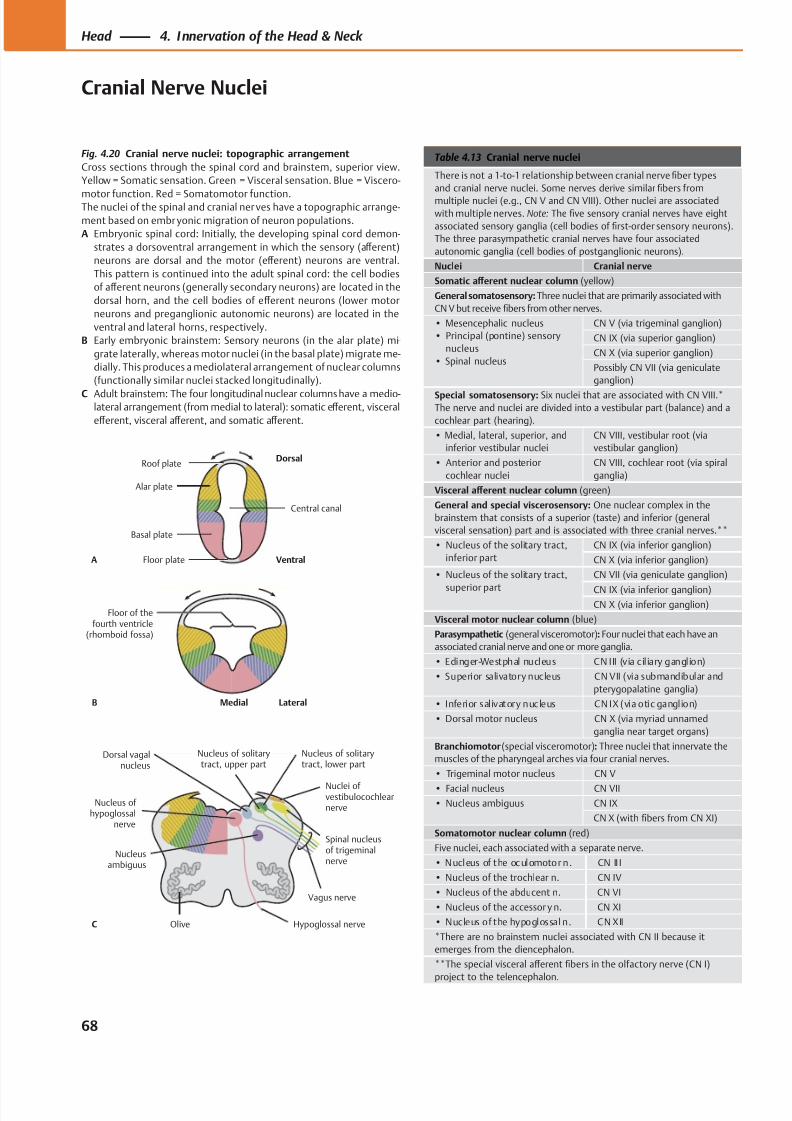
8/15/2019 Head and Neck Anatomy for Dental Medicine - Thieme; (January 26, 2010)
http://slidepdf.com/reader/full/head-and-neck-anatomy-for-dental-medicine-thieme-january-26-2010 81/384
C
Alar plate
Roof plateDorsal
Ventral
Basal plate
Floor plate
Central canal
A
B
Floor of thefourth ventricle
(rhomboid fossa)
Olive Hypoglossal nerve
Vagus nerve
Nucleusambiguus
Nuclei ofvestibulocochlearnerve
Nucleus of solitarytract, lower part
Dorsal vagalnucleus
Nucleus of solitarytract, upper part
Nucleus of hypoglossal
nerve
Spinal nucleusof trigeminalnerve
LateralMedial
Table 4.13 Cranial nerve nuclei
There is not a 1-to-1 relationship between cranial nerve fiber types
and cranial nerve nuclei. Some nerves derive similar fibers from
multiple nuclei (e.g., CN V and CN VIII). Other nuclei are associated
with multiple nerves. Note: The five sensory cranial nerves have eight
associated sensory ganglia (cell bodies of first-order sensory neurons).
The three parasympathetic cranial nerves have four associated
autonomic ganglia (cell bodies of postganglionic neurons).
Nuclei Cranial nerve
Somatic aff erent nuclear column (yellow)
General somatosensory: Three nuclei that are primarily associated with
CN V but receive fibers from other nerves.
• Mesencephalic nucleus
• Principal (pontine) sensory
nucleus
• Spinal nucleus
CN V (via trigeminal ganglion)
CN IX (via superior ganglion)
CN X (via superior ganglion)
Possibly CN VII (via geniculate
ganglion)
Special somatosensory: Six nuclei that are associated with CN VIII.*The nerve and nuclei are divided into a vestibular part (balance) and a
cochlear part (hearing).
• Medial, lateral, superior, and
inferior vestibular nuclei
CN VIII, vestibular root (via
vestibular ganglion)
• Anterior and posterior
cochlear nuclei
CN VIII, cochlear root (via spiral
ganglia)
Visceral aff erent nuclear column (green)
General and special viscerosensory: One nuclear complex in the
brainstem that consists of a superior (taste) and inferior (general
visceral sensation) part and is associated with three cranial nerves.**
• Nucleus of the solitary tract,
inferior part
CN IX (via inferior ganglion)
CN X (via inferior ganglion)
• Nucleus of the solitary tract,
superior part
CN VII (via geniculate ganglion)
CN IX (via inferior ganglion)CN X (via inferior ganglion)
Visceral motor nuclear column (blue)
Parasympathetic (general visceromotor): Four nuclei that each have an
associated cranial nerve and one or more ganglia.
• Edinger-Westphal nucleus CN III (v ia cil iary ganglion)
• Superior salivatory nucleus CN VII (via submandibular and
pterygopalatine ganglia)
• Inferior salivatory nucleus CN IX (via otic ganglion)
• Dorsal motor nucleus CN X (via myriad unnamed
ganglia near target organs)
Branchiomotor (special visceromotor): Three nuclei that innervate the
muscles of the pharyngeal arches via four cranial nerves.
• Trigeminal motor nucleus CN V
• Facial nucleus CN VII
• Nucleus ambiguus CN IX
CN X (with fibers from CN XI)
Somatomotor nuclear column (red)
Five nuclei, each associated with a separate nerve.
• Nucleus of the oculomotor n. CN II I
• Nucleus of the trochlear n. CN IV
• Nucleus of the abducent n. CN VI
• Nucleus of the accessor y n. CN XI
• Nucleus of the hypoglossal n. CN XII
*There are no brainstem nuclei associated with CN II because it
emerges from the diencephalon.
**The special visceral aff erent fibers in the olfactory nerve (CN I)
project to the telencephalon.
Fig. 4.20 Cranial nerve nuclei: topographic arrangement
Cross sections through the spinal cord and brainstem, superior view.
Yellow = Somatic sensation. Green = Visceral sensation. Blue = Viscero-
motor function. Red = Somatomotor function.The nuclei of the spinal and cranial ner ves have a topographic arrange-
ment based on embr yonic migration of neuron populations.
A Embryonic spinal cord: Initially, the developing spinal cord demon-
strates a dorsoventral arrangement in which the sensory (aff erent)
neurons are dorsal and the motor (eff erent) neurons are ventral.
This pattern is continued into the adult spinal cord: the cell bodies
of aff erent neurons (generally secondary neurons) are located in the
dorsal horn, and the cell bodies of eff erent neurons (lower motor
neurons and preganglionic autonomic neurons) are located in the
ventral and lateral horns, respectively.
B Early embryonic brainstem: Sensory neurons (in the alar plate) mi-
grate laterally, whereas motor nuclei (in the basal plate) migrate me-
dially. This produces a mediolateral arrangement of nuclear columns
(functionally similar nuclei stacked longitudinally).
C Adult brainstem: The four longitudinal nuclear columns have a medio-lateral arrangement (from medial to lateral): somatic eff erent, visceral
eff erent, visceral aff erent, and somatic aff erent.
68
Head 4. Innervation of the Head & Neck
Cranial Nerve Nuclei
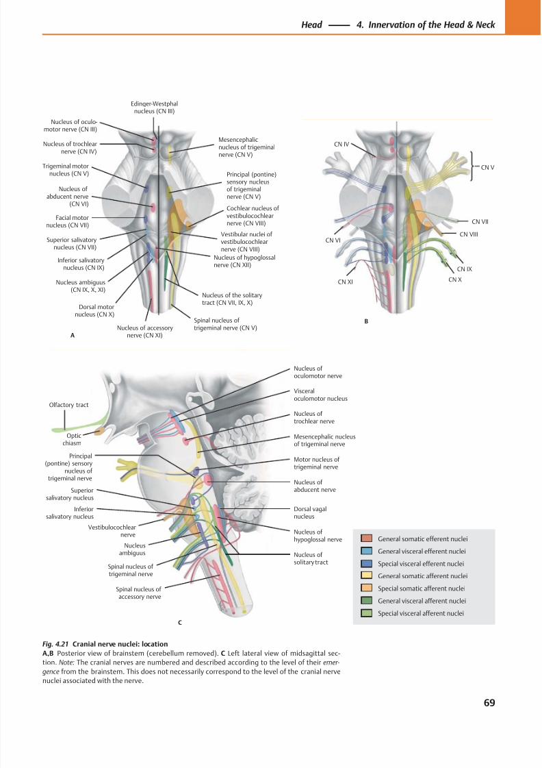
8/15/2019 Head and Neck Anatomy for Dental Medicine - Thieme; (January 26, 2010)
http://slidepdf.com/reader/full/head-and-neck-anatomy-for-dental-medicine-thieme-january-26-2010 82/384
Olfactory tract
Superiorsalivatory nucleus
Inferiorsalivatory nucleus
Nucleusambiguus Nucleus of
solitary tract
Nucleus of
hypoglossal nerve
Dorsal vagalnucleus
Spinal nucleus of trigeminal nerve
Principal(pontine) sensory
nucleus of trigeminal nerve
Nucleus of abducent nerve
Motor nucleus of trigeminal nerve
Mesencephalic nucleusof trigeminal nerve
Nucleus of trochlear nerve
Nucleus of oculomotor nerve
Visceraloculomotor nucleus
C
Spinal nucleus of accessory nerve
Opticchiasm
Vestibulocochlear
nerve
Nucleus of trochlearnerve (CN IV)
Trigeminal motornucleus (CN V)
Facial motornucleus (CN VII)
Nucleus ofabducent nerve
(CN VI)
Superior salivatorynucleus (CN VII)
Inferior salivatory
nucleus (CN IX)
Nucleus ambiguus(CN IX, X, XI)
Dorsal motornucleus (CN X)
Nucleus of hypoglossalnerve (CN XII)
Nucleus of accessorynerve (CN XI)
Spinal nucleus oftrigeminal nerve (CN V)
Vestibular nuclei ofvestibulocochlearnerve (CN VIII)
Cochlear nucleus ofvestibulocochlearnerve (CN VIII)
Nucleus of the solitarytract (CN VII, IX, X)
Principal (pontine)sensory nucleusof trigeminalnerve (CN V)
Mesencephalicnucleus of trigeminalnerve (CN V)
Edinger-Westphalnucleus (CN III)
A
Nucleus of oculo-motor nerve (CN III)
CN XI
CN VI
CN IV
CN X
CN IX
CN VIII
CN VII
CN V
B
General somatic efferent nuclei
General visceral efferent nuclei
Special visceral efferent nuclei
General somatic afferent nuclei
Special somatic afferent nuclei
General visceral afferent nuclei
Special visceral afferent nuclei
Fig. 4.21 Cranial nerve nuclei: location
A,B Posterior view of brainstem (cerebellum removed). C Left lateral view of midsagittal sec-
tion. Note: The cranial nerves are numbered and described according to the level of their emer-
gence from the brainstem. This does not necessarily correspond to the level of the cranial nervenuclei associated with the nerve.
69
Head 4. Innervation of the Head & Neck
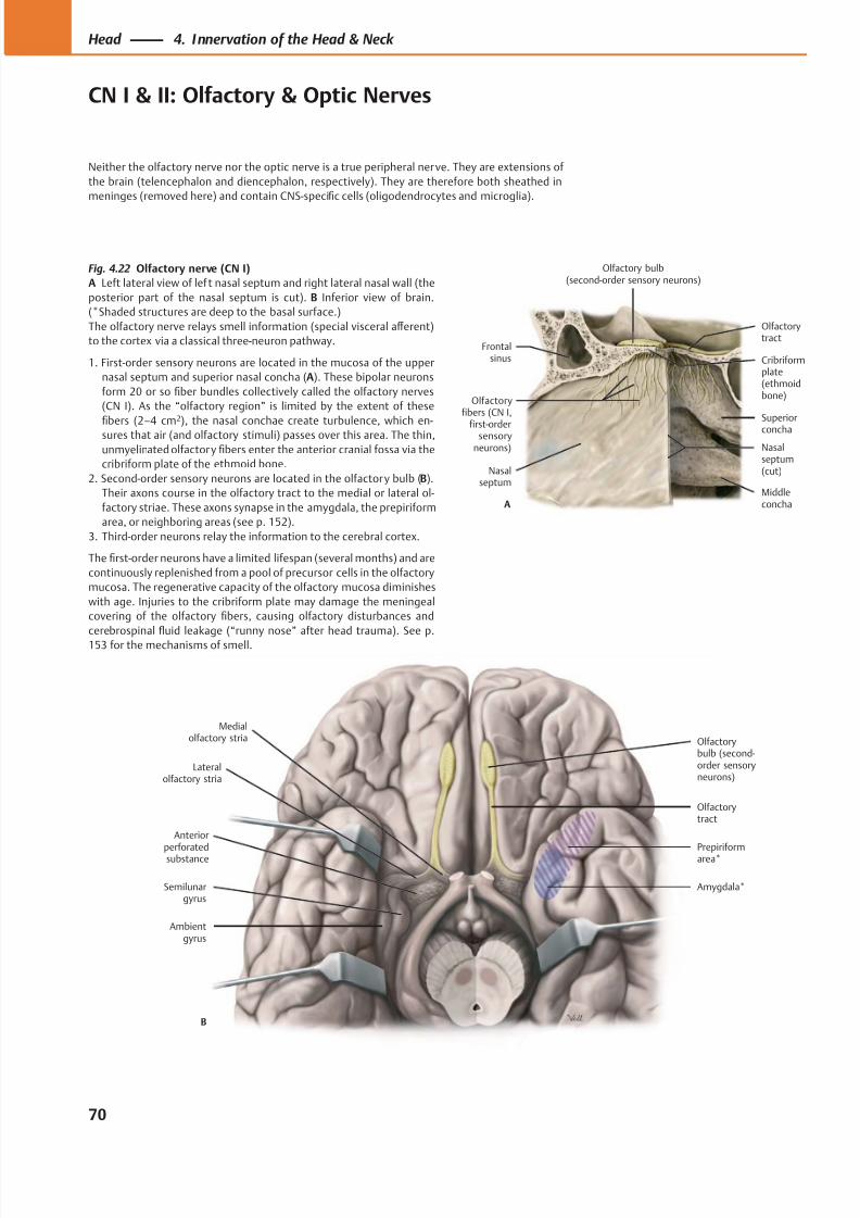
8/15/2019 Head and Neck Anatomy for Dental Medicine - Thieme; (January 26, 2010)
http://slidepdf.com/reader/full/head-and-neck-anatomy-for-dental-medicine-thieme-january-26-2010 83/384
Anteriorperforatedsubstance
Lateralolfactory stria
Medialolfactory stria Olfactory
bulb (second-order sensoryneurons)
Ambientgyrus
Semilunargyrus
Amygdala*
Prepiriformarea*
Olfactorytract
B
Olfactory bulb(second-order sensory neurons)
Olfactoryfibers (CN I,
first-ordersensory
neurons)
Olfactorytract
Superior
concha
Frontalsinus
Nasalseptum
Cribriformplate(ethmoidbone)
Nasalseptum(cut)
MiddleconchaA
Fig. 4.22 Olfactory nerve (CN I)
A Left lateral view of lef t nasal septum and right lateral nasal wall (the
posterior part of the nasal septum is cut). B Inferior view of brain.
(*Shaded structures are deep to the basal surface.)
The olfactory nerve relays smell information (special visceral aff erent)
to the cortex via a classical three-neuron pathway.
1. First-order sensory neurons are located in the mucosa of the upper
nasal septum and superior nasal concha (A). These bipolar neurons
form 20 or so fiber bundles collectively called the olfactory nerves
(CN I). As the “olfactory region” is limited by the extent of these
fibers (2–4 cm
2
), the nasal conchae create turbulence, which en-sures that air (and olfactory stimuli) passes over this area. The thin,
unmyelinated olfactory fibers enter the anterior cranial fossa via the
cribriform plate of the ethmoid bone.
2. Second-order sensory neurons are located in the olfactory bulb (B).
Their axons course in the olfactory tract to the medial or lateral ol-
factory striae. These axons synapse in the amygdala, the prepiriform
area, or neighboring areas (see p. 152).
3. Third-order neurons relay the information to the cerebral cortex.
The first-order neurons have a limited lifespan (several months) and are
continuously replenished from a pool of precursor cells in the olfactory
mucosa. The regenerative capacity of the olfactory mucosa diminishes
with age. Injuries to the cribriform plate may damage the meningeal
covering of the olfactory fibers, causing olfactory disturbances and
cerebrospinal fluid leakage (“runny nose” after head trauma). See p.
153 f or the mechanisms of smell.
70
Head 4. Innervation of the Head & Neck
CN I & II: Olfactory & Optic Nerves
Neither the olfactory nerve nor the optic nerve is a true peripheral nerve. They are extensions of
the brain (telencephalon and diencephalon, respectively). They are therefore both sheathed in
meninges (removed here) and contain CNS-specific cells (oligodendrocytes and microglia).
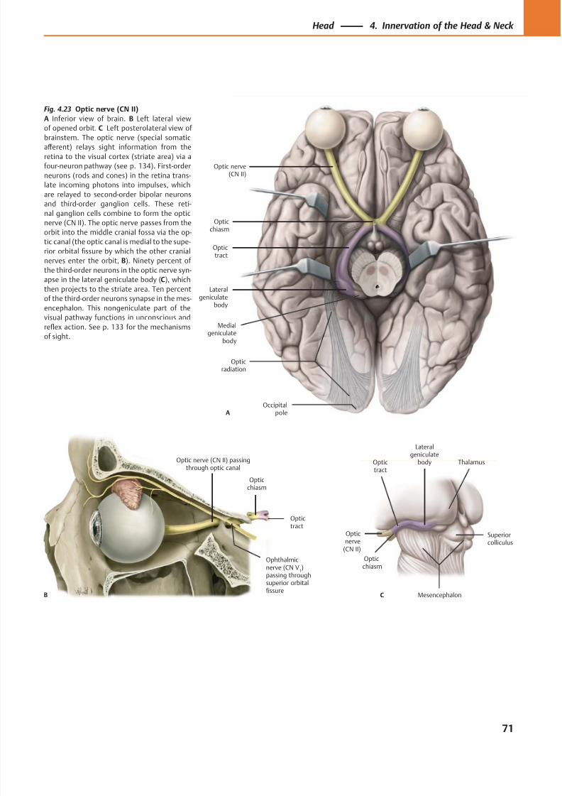
8/15/2019 Head and Neck Anatomy for Dental Medicine - Thieme; (January 26, 2010)
http://slidepdf.com/reader/full/head-and-neck-anatomy-for-dental-medicine-thieme-january-26-2010 84/384
Occipitalpole
Opticradiation
Lateralgeniculate
body
Medialgeniculate
body
Optictract
Opticchiasm
Optic nerve(CN II)
A
Optictract
Opticchiasm
Ophthalmicnerve (CN V
1)
passing throughsuperior orbitalfissure
Optic nerve (CN II) passingthrough optic canal
B
Lateralgeniculate
bodyOptictract
Opticchiasm
Opticnerve
(CN II)
C Mesencephalon
Thalamus
Superiorcolliculus
Fig. 4.23 Optic nerve (CN II)
A Inferior view of brain. B Left lateral view
of opened orbit. C Left posterolateral view of
brainstem. The optic nerve (special somaticaff erent) relays sight information from the
retina to the visual cortex (striate area) via a
four-neuron pathway (see p. 134). First-order
neurons (rods and cones) in the retina trans-
late incoming photons into impulses, which
are relayed to second-order bipolar neurons
and third-order ganglion cells. These reti-
nal ganglion cells combine to form the optic
nerve (CN II). The optic nerve passes from the
orbit into the middle cranial fossa via the op-
tic canal (the optic canal is medial to the supe-
rior orbital fissure by which the other cranial
nerves enter the orbit, B). Ninety percent of
the third-order neurons in the optic nerve syn-
apse in the lateral geniculate body (C), whichthen projects to the striate area. Ten percent
of the third-order neurons synapse in the mes-
encephalon. This nongeniculate part of the
visual pathway functions in unconscious and
reflex action. See p. 133 for the mechanisms
of sight.
71
Head 4. Innervation of the Head & Neck
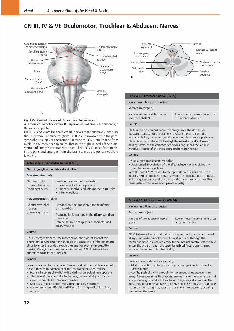
8/15/2019 Head and Neck Anatomy for Dental Medicine - Thieme; (January 26, 2010)
http://slidepdf.com/reader/full/head-and-neck-anatomy-for-dental-medicine-thieme-january-26-2010 85/384
Edinger-Westphalnucleus
Abducent nerve(CN VI)
Trochlear nerve(CN IV)
Oculomotor nerve(CN III)
Cerebral pedunclesof mesencephalon
Medullaoblongata
Nucleus of abducent nerve
Nucleus of trochlear nerve
Nucleus of oculomotornerve
Pons
A
Nucleus of oculo-motor nerve
Edinger-Westphalnucleus
Cerebralpeduncle
Cerebralaqueduct
Tectum
Central graysubstance
Red nucleus
Substantianigra
B
Table 4.16 Abducent nerve (CN VI)
Nucleus and fiber distribution
Somatomotor (red)
Nucleus of the abducent nerve
(pons)
Lower motor neurons innervate:
• Lateral rectus
Course
CN VI follows a long extradural path. It emerges from the pontomed-
ullary junction (inferior border of pons) and runs through the
cavernous sinus in close proximity to the internal carotid artery. CN VI
enters the orbit through the superior orbital fissure and courses
through the common tendinous ring.
Lesions
Lesions cause abducent nerve palsy:
• Medial deviation of the aff ected eye, causing diplopia = disabled
lateral rectus
Note: The path of CN VI through the cavernous sinus exposes it to
injury. Cavernous sinus thrombosis, aneurysms of the internal carotid
artery, meningitis, and subdural hemorrhage may all compress the
nerve, resulting in nerve palsy. Excessive fall in CSF pressure (e.g., due
to lumbar puncture) may cause the brainstem to descend, exerting
traction on the nerve.
Table 4.15 Trochlear nerve (CN IV)
Nucleus and fiber distribution
Somatomotor (red)
Nucleus of the trochlear nerve
(mesencephalon)
Lower motor neurons innervate:
• Superior oblique
Course
CN IV is the only cranial nerve to emerge from the dorsal side
(posterior surface) of the brainstem. After emerging from the
mesencephalon, it courses anteriorly around the cerebral peduncle.
CN IV then enters the orbit through the superior orbital fissure,
passing lateral to the common tendinous ring. It has the longest
intradural course of the three extraocular motor nerves.
Lesions
Lesions cause trochlear nerve palsy:
• Superomedial deviation of the aff ected eye, causing diplopia =
disabled superior oblique
Note: Because CN IV crosses to the opposite side, lesions close to the
nucleus result in trochlear nerve palsy on the opposite side (contralat-
eral palsy). Lesions past the site where the nerve crosses the midline
cause palsy on the same side (ipsilateral palsy).
Table 4.14 Oculomotor nerve (CN III)
Nuclei, ganglion, and fiber distribution
Somatomotor (red)
Nucleus of the
oculomotor nerve
(mesencephalon)
Lower motor neurons innervate:
• Levator palpebrae superioris
• Superior, medial, and inferior rectus muscles
• Inferior oblique
Parasympathetic (blue)
Edinger-Westphal
nucleus
(mesencephalon)
Preganglionic neurons travel in the inferior
division of CN III
Postganglionic neurons in the ciliary ganglion
innervate:
Intraocular muscles (pupillary sphincter and
ciliary muscle)
Course
CN III emerges from the mesencephalon, the highest level of the
brainstem. It runs anteriorly through the lateral wall of the cavernous
sinus to enter the orbit through the superior orbital fissure. After
passing through the common tendinous ring, CN III divides into a
superior and an inferior division.
Lesions
Lesions cause oculomotor palsy of various extents. Complete oculomotor
palsy is marked by paralysis of all the innervated muscles, causing:
• Ptosis (drooping of eyelid) = disabled levator palpebrae superioris
• Inferolateral deviation of aff ected eye, causing diplopia (double
vision) = disabled extraocular muscles
• Mydriasis (pupil dilation) = disabled pupillary sphincter
• Accommodation diffi culties (diffi culty focusing) = disabled ciliary
muscle
Fig. 4.24 Cranial nerves of the extraocular muscles
A Anterior view of brainstem. B Superior view of cross section through
the mesencephalon.
CN III, IV, and VI are the three cranial nerves that collectively innervate
the six extraocular muscles. (Note: CN III is also involved with the para-
sympathetic supply to the intraocular muscles.) CN III and IV arise from
nuclei in the mesencephalon (midbrain, the highest level of the brain-
stem) and emerge at roughly the same level. CN VI arises from nuclei
in the pons and emerges from the brainstem at the pontomedullary
junction.
72
Head 4. Innervation of the Head & Neck
CN III, IV & VI: Oculomotor, Trochlear & Abducent Nerves
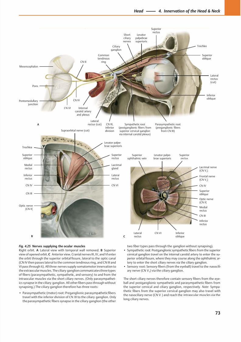
8/15/2019 Head and Neck Anatomy for Dental Medicine - Thieme; (January 26, 2010)
http://slidepdf.com/reader/full/head-and-neck-anatomy-for-dental-medicine-thieme-january-26-2010 86/384
CN VI
CN III
CN IV
Frontal nerve
(CN V1)
Lacrimal nerve(CN V
1)
Superiorophthalmic vein
Inferioroblique
Superioroblique
Levator palpe-brae superioris
Superiorrectus
Lateralrectus
Inferiorrectus
Medialrectus
Optic nerve(CN II)
C
Supraorbital nerve (cut)
CN VICN IV
CN III
Optic nerve(CN II)
Lacrimalgland
Levator palpe-brae superioris
Superioroblique
Lateral
rectus
Inferior
rectus
Medialrectus
Superiorrectus
B
Trochlea
Lateralrectus(cut)
Inferioroblique
CN III,inferiordivision
Levatorpalpebraesuperioris
Superiorrectus
Superior
oblique
Ciliaryganglion
CN VI
CN IV
CN III
Sympathetic root(postganglionic fibers fromsuperior cervical ganglionvia internal carotid plexus)
Common
tendinousring
Lateralrectus (cut)A
Trochlea
Shortciliarynerves
Mesencephalon
Pons
Pontomedullary junction
Internalcarotid artery
and plexus
Parasympathetic root(preganglionic fibers
from CN III)
Fig. 4.25 Nerves supplying the ocular muscles
Right orbit. A Lateral view with temporal wall removed. B Superior
view of opened orbit. C Anterior view. Cranial nerves III, IV, and VI enter
the orbit through the superior orbital fissure, lateral to the optic canal
(CN IV then passes lateral to the common tendinous ring, and CN III and
VI pass through it). All three nerves supply somatomotor innervation to
the extraocular muscles. The ciliary ganglion communicates three types
of fibers (parasympathetic, sympathetic, and sensory) to and from the
intraocular muscles via the short ciliary nerves. (Only parasympathet-
ics synapse in the ciliary ganglion. All other fibers pass through without
synapsing.) The ciliary ganglion therefore has three roots:
• Parasympathetic (motor) root: Preganglionic parasympathetic fibers
travel with the inferior division of CN III to the ciliary ganglion. Only
the parasympathetic fibers synapse in the ciliary ganglion (the other
two fiber types pass through the ganglion without synapsing).
• Sympathetic root: Postganglionic sympathetic fibers from the superior
cervical ganglion travel on the internal carotid artery to enter the su-
perior orbital fissure, where they may course along the ophthalmic ar-
tery to enter the short ciliary nerves via the ciliary ganglion.
• Sensory root: Sensory fibers (from the eyeball) travel to the nasocili-
ary nerve (CN V1) via the ciliary ganglion.
The short ciliary nerves therefore contain sensory fibers from the eye-
ball and postganglionic sympathetic and parasympathetic fibers from
the superior cervical and ciliary ganglion, respectively. Note: Sympa-
thetic fibers from the superior cervical ganglion may also travel with
the nasociliary nerve (CN V1) and reach the intraocular muscles via the
long ciliary nerves.
73
Head 4. Innervation of the Head & Neck
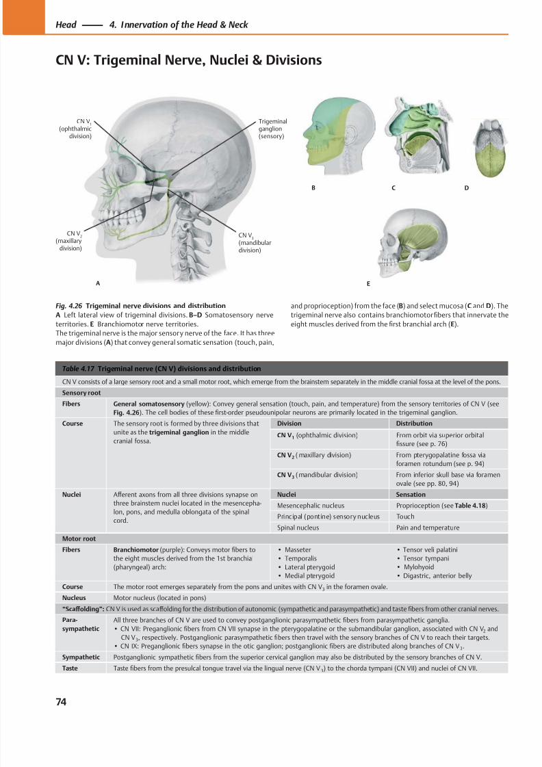
8/15/2019 Head and Neck Anatomy for Dental Medicine - Thieme; (January 26, 2010)
http://slidepdf.com/reader/full/head-and-neck-anatomy-for-dental-medicine-thieme-january-26-2010 87/384
A
CN V1
(ophthalmic
division)
CN V2
(maxillarydivision)
CN V3
(mandibulardivision)
Trigeminalganglion
(sensory)
B C D
E
Table 4.17 Trigeminal nerve (CN V) divisions and distribution
CN V consists of a large sensory root and a small motor root, which emerge from the brainstem separately in the middle cranial fossa at the level of the pons.
Sensory root
Fibers General somatosensory (yellow): Convey general sensation (touch, pain, and temperature) from the sensory territories of CN V (seeFig. 4.26). The cell bodies of these first-order pseudounipolar neurons are primarily located in the trigeminal ganglion.
Course The sensory root is formed by three divisions that
unite as the trigeminal ganglion in the middle
cranial fossa.
Division Distribution
CN V1 (ophthalmic division) From orbit via superior orbital
fissure (see p. 76)
CN V2 ( maxillary division) From pterygopalatine fossa via
foramen rotundum (see p. 94)
CN V3 ( mandibular division) From inferior skull base via foramen
ovale (see pp. 80, 94)
Nuclei Aff erent axons from all three divisions synapse on
three brainstem nuclei located in the mesencepha-
lon, pons, and medulla oblongata of the spinal
cord.
Nuclei Sensation
Mesencephalic nucleus Proprioception (see Table 4.18)
Principal (pontine) sensory nucleus Touch
Spinal nucleus Pain and temperature
Motor root
Fibers Branchiomotor (purple): Conveys motor fibers to
the eight muscles derived from the 1st branchial
(pharyngeal) arch:
• Masseter
• Temporalis
• Lateral pterygoid
• Medial pterygoid
• Tensor veli palatini
• Tensor tympani
• Mylohyoid
• Digastric, anterior belly
Course The motor root emerges separately from the pons and unites with CN V 3 in the foramen ovale.
Nucleus Motor nucleus (located in pons)
“Scaff olding”: CN V is used as scaff olding for the distribution of autonomic (sympathetic and parasympathetic) and taste fibers from other cranial nerves.
Para-
sympathetic
All three branches of CN V are used to convey postganglionic parasympathetic fibers from parasympathetic ganglia.
• CN VII: Preganglionic fibers from CN VII synapse in the pterygopalatine or the submandibular ganglion, associated with CN V2 and
CN V3, respectively. Postganglionic parasympathetic fibers then travel with the sensory branches of CN V to reach their targets.
• CN IX: Preganglionic fibers synapse in the otic ganglion; postganglionic fibers are distributed along branches of CN V 3.
Sympathetic Postganglionic sympathetic fibers from the superior cervical ganglion may also be distributed by the sensory branches of CN V.
Taste Tastefi
bers from the presulcal tongue travel via the lingual nerve (CN V 3) to the chorda tympani (CN VII) and nuclei of CN VII.
Fig. 4.26 Trigeminal nerve divisions and distribution
A Left lateral view of trigeminal divisions. B–D Somatosensory nerve
territories. E Branchiomotor nerve territories.
The trigeminal nerve is the major sensory nerve of the face. It has three
major divisions (A) that convey general somatic sensation (touch, pain,
and proprioception) from the face (B) and select mucosa (C and D). The
trigeminal nerve also contains branchiomotor fibers that innervate the
eight muscles derived from the first branchial arch (E).
74
Head 4. Innervation of the Head & Neck
CN V: Trigeminal Nerve, Nuclei & Divisions
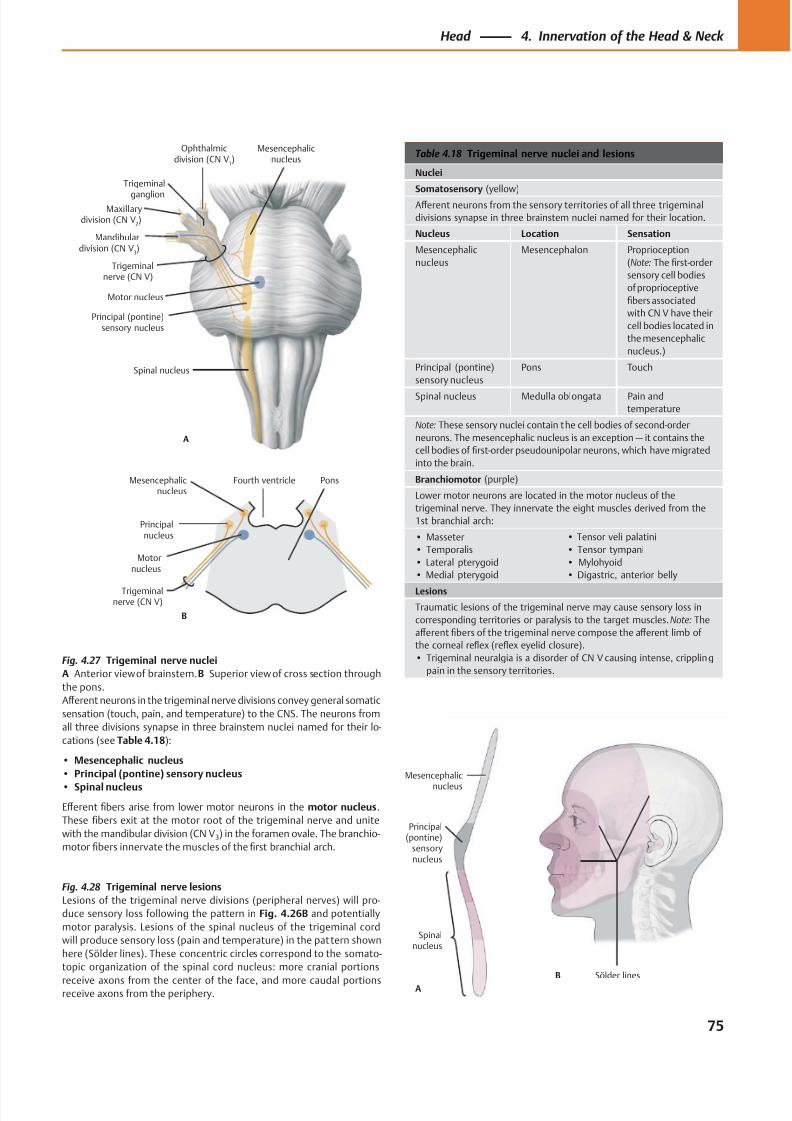
8/15/2019 Head and Neck Anatomy for Dental Medicine - Thieme; (January 26, 2010)
http://slidepdf.com/reader/full/head-and-neck-anatomy-for-dental-medicine-thieme-january-26-2010 88/384
Motor nucleus
Principal (pontine)sensory nucleus
Mesencephalicnucleus
Spinal nucleus
A
Maxillarydivision (CN V
2)
Ophthalmicdivision (CN V
1)
Trigeminal
ganglion
Trigeminalnerve (CN V)
Mandibulardivision (CN V
3)
Motornucleus
Principalnucleus
Mesencephalicnucleus
B
Trigeminalnerve (CN V)
PonsFourth ventricle
A
B
Spinalnucleus
Mesencephalic
nucleus
Principal(pontine)
sensorynucleus
Sölder lines
Table 4.18 Trigeminal nerve nuclei and lesions
Nuclei
Somatosensory (yellow)
Aff erent neurons from the sensory territories of all three trigeminal
divisions synapse in three brainstem nuclei named for their location.
Nucleus Location Sensation
Mesencephalic
nucleus
Mesencephalon Proprioception
(Note: The first-order
sensory cell bodies
of proprioceptive
fibers associated
with CN V have their
cell bodies located in
the mesencephalic
nucleus.)
Principal (pontine)
sensory nucleus
Pons Touch
Spinal nucleus Medulla oblongata Pain and
temperature
Note: These sensory nuclei contain the cell bodies of second-order
neurons. The mesencephalic nucleus is an exception — it contains the
cell bodies of first-order pseudounipolar neurons, which have migrated
into the brain.
Branchiomotor (purple)
Lower motor neurons are located in the motor nucleus of the
trigeminal nerve. They innervate the eight muscles derived from the
1st branchial arch:
• Masseter
• Temporalis
• Lateral pterygoid
• Medial pterygoid
• Tensor veli palatini
• Tensor tympani
• Mylohyoid
• Digastric, anterior belly
Lesions
Traumatic lesions of the trigeminal nerve may cause sensory loss in
corresponding territories or paralysis to the target muscles. Note: The
aff erent fibers of the trigeminal nerve compose the aff erent limb of
the corneal reflex (reflex eyelid closure).
• Trigeminal neuralgia is a disorder of CN V causing intense, crippling
pain in the sensory territories.
Fig. 4.28 Trigeminal nerve lesions
Lesions of the trigeminal nerve divisions (peripheral nerves) will pro-
duce sensory loss following the pattern in Fig. 4.26B and potentially
motor paralysis. Lesions of the spinal nucleus of the trigeminal cord
will produce sensory loss (pain and temperature) in the pattern shown
here (Sölder lines). These concentric circles correspond to the somato-
topic organization of the spinal cord nucleus: more cranial portions
receive axons from the center of the face, and more caudal portionsreceive axons from the periphery.
Fig. 4.27 Trigeminal nerve nuclei
A Anterior view of brainstem. B Superior view of cross section through
the pons.
Aff erent neurons in the trigeminal nerve divisions convey general somatic
sensation (touch, pain, and temperature) to the CNS. The neurons from
all three divisions synapse in three brainstem nuclei named for their lo-
cations (see Table 4.18):
• Mesencephalic nucleus
• Principal (pontine) sensory nucleus
• Spinal nucleus
Eff erent fibers arise from lower motor neurons in the motor nucleus.
These fibers exit at the motor root of the trigeminal nerve and unite
with the mandibular division (CN V3) in the foramen ovale. The branchio-
motor fibers innervate the muscles of the first branchial arch.
75
Head 4. Innervation of the Head & Neck
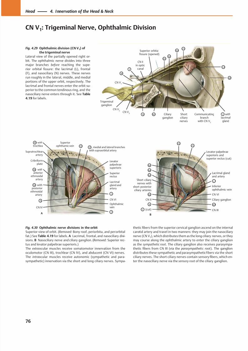
8/15/2019 Head and Neck Anatomy for Dental Medicine - Thieme; (January 26, 2010)
http://slidepdf.com/reader/full/head-and-neck-anatomy-for-dental-medicine-thieme-january-26-2010 89/384
Ciliaryganglion
CN V1
Trigeminalganglion
withlacrimal
gland
Shortciliarynerves
Superior orbitalfissure (opened)
F1
F2
N5
N4
N3N2
CN IIin optic
canalF
M
CN V3
CN V2
N N1 Communicatingbranch
with CN V2
L
Levatorpalpebraesuperioris
CN VI
Lacrimal
gland andartery
Ophthalmicvein
Cribriformplate
Supratrochlearartery
CN IV
Superiorophthamic vein
Superiorrectus
withtrochlea
withposterior
ethmoidalartery
withanterior
ethmoidalartery
, medial and lateral brancheswith supraorbital artery
A
F2
L
F1
F
N5
N
N4
N3
(cut)
Short ciliary
nerves withshort posteriorciliary arteries
CN II
N5
N4
N3
F
N
N2
B
Levator palpebraesuperioris andsuperior rectus (cut)
Lacrimal glandand artery
Ciliary ganglion
Inferiorophthalmic vein
CN VI
CN III
L
N1
F1F2
Fig. 4.30 Ophthalmic nerve divisions in the orbit
Superior view of orbit. (Removed: Bony roof, periorbita, and periorbital
fat.) See Table 4.19 f or labels. A Lacrimal, frontal, and nasociliary divi-
sions. B Nasociliary nerve and ciliary ganglion. (Removed: Superior rec-
tus and levator palpebrae superioris.)The extraocular muscles receive somatomotor innervation from the
oculomotor (CN III), trochlear (CN IV), and abducent (CN VI) nerves.
The intraocular muscles receive autonomic (sympathetic and para-
sympathetic) innervation via the short and long ciliary nerves. Sympa-
thetic fibers from the superior cervical ganglion ascend on the internal
carotid artery and travel in two manners: they may join the nasociliary
nerve (CN V1), which distributes them as the long ciliary nerves, or they
may course along the ophthalmic artery to enter the ciliary ganglion
as the sympathetic root . The ciliary ganglion also receives parasympa-thetic fibers from CN III (via the parasympathetic root ). The ganglion
distributes these sympathetic and parasympathetic fibers via the short
ciliary nerves. The short ciliary nerves contain sensory fibers, which en-
ter the nasociliary nerve via the sensory root of the ciliary ganglion.
Fig. 4.29 Ophthalmic division (CN V1) of
the trigeminal nerve
Lateral view of the partially opened right or-
bit. The ophthalmic nerve divides into threemajor branches before reaching the supe-
rior orbital fissure: the lacrimal (L), frontal
(F), and nasociliary (N) nerves. These nerves
run roughly in the lateral, middle, and medial
portions of the upper orbit, respectively. The
lacrimal and frontal nerves enter the orbit su-
perior to the common tendinous ring, and the
nasociliary nerve enters through it. See Table
4.19 f or labels.
76
Head 4. Innervation of the Head & Neck
CN V1: Trigeminal Nerve, Ophthalmic Division
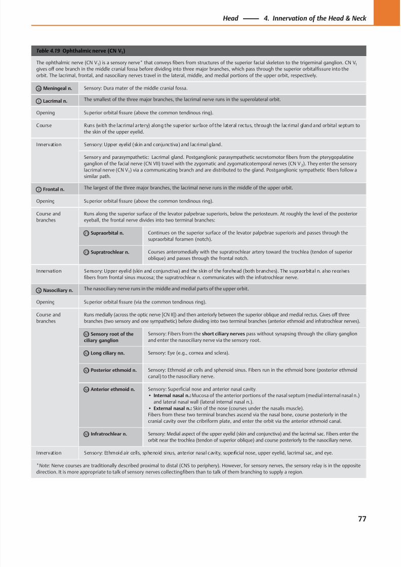
8/15/2019 Head and Neck Anatomy for Dental Medicine - Thieme; (January 26, 2010)
http://slidepdf.com/reader/full/head-and-neck-anatomy-for-dental-medicine-thieme-january-26-2010 90/384
Table 4.19 Ophthalmic nerve (CN V1)
The ophthalmic nerve (CN V1) is a sensory nerve* that conveys fibers from structures of the superior facial skeleton to the trigeminal ganglion. CN V1
gives off one branch in the middle cranial fossa before dividing into three major branches, which pass through the superior orbital fissure into the
orbit. The lacrimal, frontal, and nasociliary nerves travel in the lateral, middle, and medial portions of the upper orbit, respectively.
M Meningeal n. Sensory: Dura mater of the middle cranial fossa.
L Lacrimal n. The smallest of the three major branches, the lacrimal nerve runs in the superolateral orbit.
Opening Superior orbital fissure (above the common tendinous ring).
Course Runs (with the lacrimal artery) along the superior surface of the lateral rectus, through the lacrimal gland and orbital septum to
the skin of the upper eyelid.
Innervation Sensory: Upper eyelid (skin and conjunctiva) and lacrimal gland.
Sensory and parasympathetic: Lacrimal gland. Postganglionic parasympathetic secretomotor fibers from the pterygopalatine
ganglion of the facial nerve (CN VII) travel with the zygomatic and zygomaticotemporal nerves (CN V 2). They enter the sensory
lacrimal nerve (CN V1) via a communicating branch and are distributed to the gland. Postganglionic sympathetic fibers follow a
similar path.
F Frontal n. The largest of the three major branches, the lacrimal nerve runs in the middle of the upper orbit.
Opening Superior orbital fissure (above the common tendinous ring).
Course and
branches
Runs along the superior surface of the levator palpebrae superioris, below the periosteum. At roughly the level of the posterior
eyeball, the frontal nerve divides into two terminal branches:
F1 Supraorbital n. Continues on the superior surface of the levator palpebrae superioris and passes through the
supraorbital foramen (notch).
F2 Supratrochlear n. Courses anteromedially with the supratrochlear artery toward the trochlea (tendon of superior
oblique) and passes through the frontal notch.
Innervation Sensory: Upper eyelid (skin and conjunctiva) and the skin of the forehead (both branches). The supraorbital n. also receives
fibers from frontal sinus mucosa; the supratrochlear n. communicates with the infratrochlear nerve.
N Nasociliary n. The nasociliary nerve runs in the middle and medial parts of the upper orbit.
Opening Superior orbital fissure (via the common tendinous ring).
Course and
branches
Runs medially (across the optic nerve [CN II]) and then anteriorly between the superior oblique and medial rectus. Gives off three
branches (two sensory and one sympathetic) before dividing into two terminal branches (anterior ethmoid and infratrochlear nerves).
N1 Sensory root of the
ciliary ganglion
Sensory: Fibers from the short ciliary nerves pass without synapsing through the ciliary ganglion
and enter the nasociliary nerve via the sensory root.
N2 Long ciliary nn. Sensory: Eye (e.g., cornea and sclera).
N3 Posterior ethmoid n. Sensory: Ethmoid air cells and sphenoid sinus. Fibers run in the ethmoid bone (posterior ethmoid
canal) to the nasociliary nerve.
N4 Anterior ethmoid n. Sensory: Superficial nose and anterior nasal cavity.
• Internal nasal n.: Mucosa of the anterior portions of the nasal septum (medial internal nasal n.)and lateral nasal wall (lateral internal nasal n.).
• External nasal n.: Skin of the nose (courses under the nasalis muscle).
Fibers from these two terminal branches ascend via the nasal bone, course posteriorly in the
cranial cavity over the cribriform plate, and enter the orbit via the anterior ethmoid canal.
N5 Infratrochlear n. Sensory: Medial aspect of the upper eyelid (skin and conjunctiva) and the lacrimal sac. Fibers enter the
orbit near the trochlea (tendon of superior oblique) and course posteriorly to the nasociliary nerve.
Innervation Sensory: Ethmoid air cells, sphenoid sinus, anterior nasal cavity, superficial nose, upper eyelid, lacrimal sac, and eye.
*Note: Nerve courses are traditionally described proximal to distal (CNS to periphery). However, for sensory nerves, the sensory relay is in the opposite
direction. It is more appropriate to talk of sensory nerves collecting fibers than to talk of them branching to supply a region.
77
Head 4. Innervation of the Head & Neck
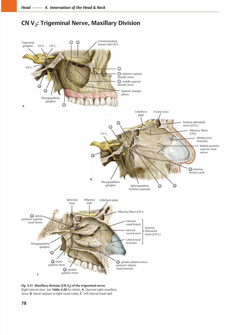
8/15/2019 Head and Neck Anatomy for Dental Medicine - Thieme; (January 26, 2010)
http://slidepdf.com/reader/full/head-and-neck-anatomy-for-dental-medicine-thieme-january-26-2010 91/384
Pterygopalatineganglion
, middle superioralveolar nerve
CN V2
Trigeminalganglion
Superior alveolarplexus
Communicatingbranch with CN V
1
ZI
CN V1
CN V3
M
G
P
I
, anterior superioralveolar nerve
I
I
A
Anterior ethmoidalnerve (CN V
1)
Frontal sinus
Olfactory fibers(CN I)
Medial nasalbranches
Medial posteriorsuperior nasalnerves
enteringincisive canal
Sphenopalatineforamen (opened)
Pterygopalatineganglion
CN V2
Cribriformplate
G1
G
M
B
G3 G2
G2
Cribriform plate
Anteriorethmoidal
nerve (CN V1)
Olfactorybulb
Externalnasal branch
Lateral nasalbranches
Internal
nasal branch
, greater palatine nerve,posterior inferiornasal branches
Sphenoidsinus
Olfactory fibers (CN I)
G4
, lateralposterior superior
nasal nerves
G3
Pterygopalatineganglion
G4
, lesserpalatine nerve
G4
, greaterpalatine nerve
G4
C
Fig. 4.31 Maxillary division (CN V2) of the trigeminal nerve
Right lateral view. See Table 4.20 for labels. A Opened right maxillary
sinus. B Nasal septum in right nasal cavity. C Left lateral nasal wall.
78
Head 4. Innervation of the Head & Neck
CN V2: Trigeminal Nerve, Maxillary Division
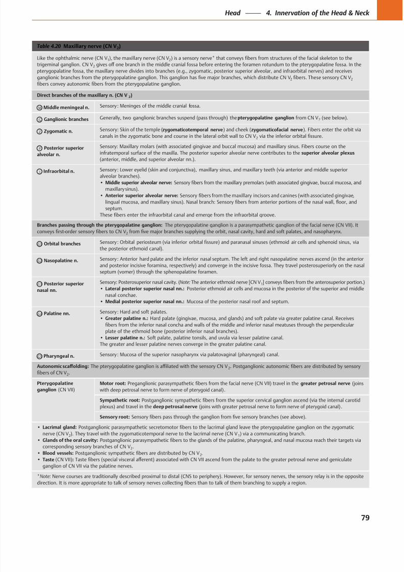
8/15/2019 Head and Neck Anatomy for Dental Medicine - Thieme; (January 26, 2010)
http://slidepdf.com/reader/full/head-and-neck-anatomy-for-dental-medicine-thieme-january-26-2010 92/384
Table 4.20 Maxillary nerve (CN V2)
Like the ophthalmic nerve (CN V1), the maxillary nerve (CN V2
trigeminal ganglion. CN V2
2 2
Direct branches of the maxillary n. (CN V2)
M Middle meningeal n.
G Ganglionic branches pterygopalatine ganglion 2
Z Zygomatic n. zygomaticotemporal nerve zygomaticofacial nerve
2
P Posterior superior
alveolar n.
superior alveolar plexus
Infraorbital n.
Middle superior alveolar nerve:
Anterior superior alveolar nerve:
Branches passing through the pterygopalatine ganglion:
2
G1 Orbital branches
G2 Nasopalatine n.
G3 Posterior superior
nasal nn.
Note: 1
Lateral posterior superior nasal nn.:
nasal conchae.
Medial posterior superior nasal nn.:
G4 Palatine nn.
Greater palatine n.:
Lesser palatine n.:
G5 Pharyngeal n.
2
2.
Pterygopalatine
ganglion
Motor root: greater petrosal nerve
.
Sympathetic root: deep petrosal nerve .
Sensory root:
Lacrimal gland:
nerve (CN V2 1
Glands of the oral cavity:
2.
Blood vessels: 2.
Taste :
*Note:
79
Head 4. Innervation of the Head & Neck
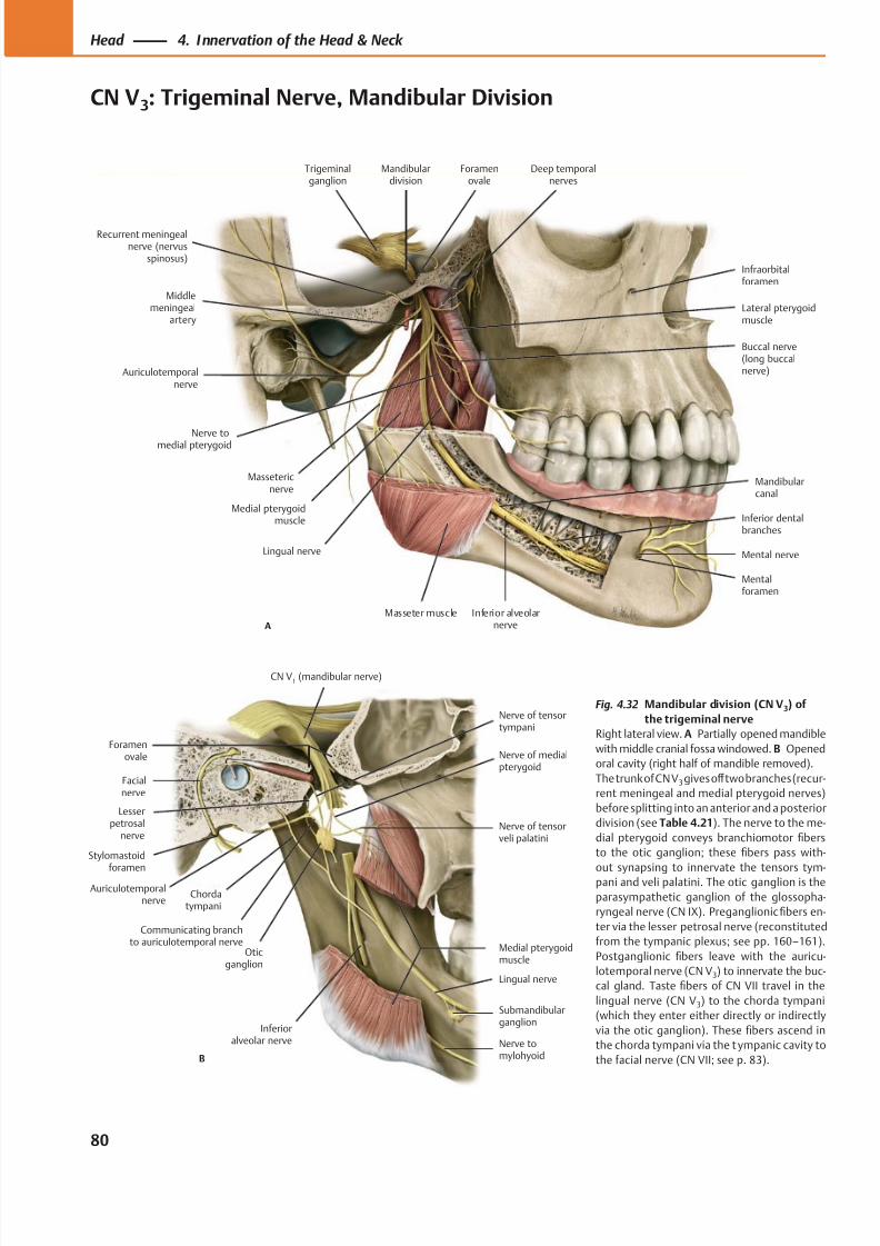
8/15/2019 Head and Neck Anatomy for Dental Medicine - Thieme; (January 26, 2010)
http://slidepdf.com/reader/full/head-and-neck-anatomy-for-dental-medicine-thieme-january-26-2010 93/384
A
Auriculotemporalnerve
Massetericnerve
Medial pterygoidmuscle
Lingual nerve
Masseter muscle Inferior alveolarnerve
Mental nerve
Deep temporalnerves
Mandibulardivision
Trigeminalganglion
Nerve tomedial pterygoid
Buccal nerve(long buccalnerve)
Mandibularcanal
Inferior dentalbranches
Mentalforamen
Middlemeningeal
artery
Foramenovale
Lateral pterygoidmuscle
Infraorbitalforamen
Recurrent meningealnerve (nervus
spinosus)
B
Nerve of tensortympani
Facialnerve
Stylomastoid
foramenAuriculotemporal
nerve
Lesserpetrosal
nerve
Communicating branchto auriculotemporal nerve
Chordatympani
Nerve tomylohyoid
Lingual nerve
Medial pterygoidmuscle
Oticganglion
Nerve of tensorveli palatini
CN V1 (mandibular nerve)
Foramenovale
Submandibularganglion
Inferioralveolar nerve
Nerve of medialpterygoid
Fig. 4.32 Mandibular division (CN V3) of
the trigeminal nerve
Right lateral view. A Partially opened mandible
with middle cranial fossa windowed. B Opened
oral cavity (right half of mandible removed).
The trunk of CN V3 gives off two branches (recur-
rent meningeal and medial pterygoid nerves)
before splitting into an anterior and a posterior
division (see Table 4.21). The nerve to the me-
dial pterygoid conveys branchiomotor fibers
to the otic ganglion; these fibers pass with-
out synapsing to innervate the tensors tym-pani and veli palatini. The otic ganglion is the
parasympathetic ganglion of the glossopha-
ryngeal nerve (CN IX). Preganglionic fibers en-
ter via the lesser petrosal nerve (reconstituted
from the tympanic plexus; see pp. 160–161).
Postganglionic fibers leave with the auricu-
lotemporal nerve (CN V3) to innervate the buc-
cal gland. Taste fibers of CN VII travel in the
lingual nerve (CN V3) to the chorda tympani
(which they enter either directly or indirectly
via the otic ganglion). These fibers ascend in
the chorda tympani via the t ympanic cavity to
the facial nerve (CN VII; see p. 83).
80
Head 4. Innervation of the Head & Neck
CN V3: Trigeminal Nerve, Mandibular Division
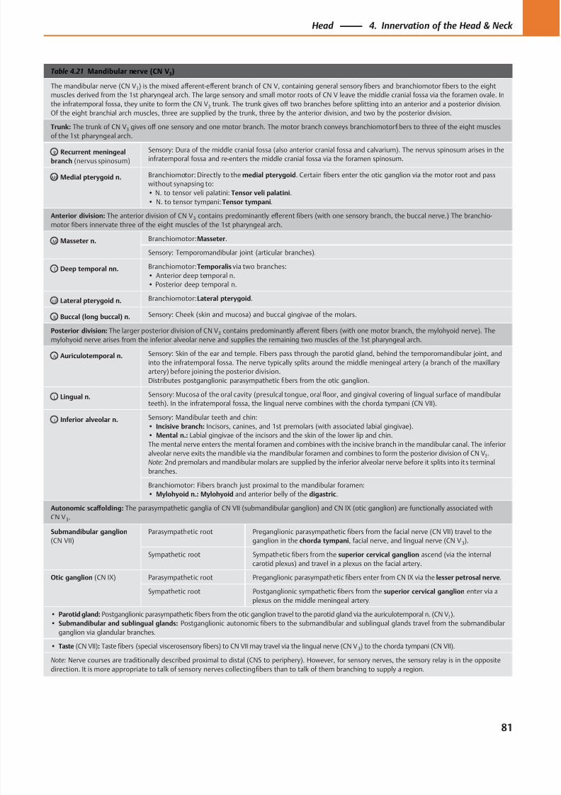
8/15/2019 Head and Neck Anatomy for Dental Medicine - Thieme; (January 26, 2010)
http://slidepdf.com/reader/full/head-and-neck-anatomy-for-dental-medicine-thieme-january-26-2010 94/384
Table 4.21 Mandibular nerve (CN V3)
The mandibular nerve (CN V3) is the mixed aff erent-eff erent branch of CN V, containing general sensory fibers and branchiomotor fibers to the eight
muscles derived from the 1st pharyngeal arch. The large sensory and small motor roots of CN V leave the middle cranial fossa via the foramen ovale. In
the infratemporal fossa, they unite to form the CN V3 trunk. The trunk gives off two branches before splitting into an anterior and a posterior division.
Of the eight branchial arch muscles, three are supplied by the trunk, three by the anterior division, and two by the posterior division.
Trunk: The trunk of CN V3 gives off one sensory and one motor branch. The motor branch conveys branchiomotor fibers to three of the eight muscles
of the 1st pharyngeal arch.
R Recurrent meningeal
branch (nervus spinosum)
Sensory: Dura of the middle cranial fossa (also anterior cranial fossa and calvarium). The nervus spinosum arises in the
infratemporal fossa and re-enters the middle cranial fossa via the foramen spinosum.
MP Medial pterygoid n. Branchiomotor: Directly to the medial pterygoid. Certain fibers enter the otic ganglion via the motor root and pass
without synapsing to:
• N. to tensor veli palatini: Tensor veli palatini.
• N. to tensor tympani: Tensor tympani.
Anterior division: The anterior division of CN V3 contains predominantly eff erent fibers (with one sensory branch, the buccal nerve.) The branchio-
motor fibers innervate three of the eight muscles of the 1st pharyngeal arch.
M Masseter n. Branchiomotor: Masseter.
Sensory: Temporomandibular joint (articular branches).
T Deep temporal nn. Branchiomotor: Temporalis via two branches:
• Anterior deep temporal n.• Posterior deep temporal n.
LP Lateral pterygoid n. Branchiomotor: Lateral pterygoid.
B Buccal (long buccal) n. Sensory: Cheek (skin and mucosa) and buccal gingivae of the molars.
Posterior division: The larger posterior division of CN V3 contains predominantly aff erent fibers (with one motor branch, the mylohyoid nerve). The
mylohyoid nerve arises from the inferior alveolar nerve and supplies the remaining two muscles of the 1st pharyngeal arch.
A Auriculotemporal n. Sensory: Skin of the ear and temple. Fibers pass through the parotid gland, behind the temporomandibular joint, and
into the infratemporal fossa. The nerve typically splits around the middle meningeal artery (a branch of the maxillary
artery) before joining the posterior division.
Distributes postganglionic parasympathetic fibers from the otic ganglion.
L Lingual n. Sensory: Mucosa of the oral cavity (presulcal tongue, oral floor, and gingival covering of lingual surface of mandibular
teeth). In the infratemporal fossa, the lingual nerve combines with the chorda tympani (CN VII).
I Inferior alveolar n. Sensory: Mandibular teeth and chin:• Incisive branch: Incisors, canines, and 1st premolars (with associated labial gingivae).
• Mental n.: Labial gingivae of the incisors and the skin of the lower lip and chin.
The mental nerve enters the mental foramen and combines with the incisive branch in the mandibular canal. The inferior
alveolar nerve exits the mandible via the mandibular foramen and combines to form the posterior division of CN V3.
Note: 2nd premolars and mandibular molars are supplied by the inferior alveolar nerve before it splits into its terminal
branches.
Branchiomotor: Fibers branch just proximal to the mandibular foramen:
• Mylohyoid n.: Mylohyoid and anterior belly of the digastric.
Autonomic scaff olding: The parasympathetic ganglia of CN VII (submandibular ganglion) and CN IX (otic ganglion) are functionally associated with
CN V3.
Submandibular ganglion
(CN VII)
Parasympathetic root Preganglionic parasympathetic fibers from the facial nerve (CN VII) travel to the
ganglion in the chorda tympani, facial nerve, and lingual nerve (CN V 3).
Sympathetic root Sympathetic fibers from the superior cervical ganglion ascend (via the internalcarotid plexus) and travel in a plexus on the facial artery.
Otic ganglion (CN IX) Parasympathetic root Preganglionic parasympathetic fibers enter from CN IX via the lesser petrosal nerve.
Sympathetic root Postganglionic sympathetic fibers from the superior cervical ganglion enter via a
plexus on the middle meningeal artery.
• Parotid gland: Postganglionic parasympathetic fibers from the otic ganglion travel to the parotid gland via the auriculotemporal n. (CN V3).
• Submandibular and sublingual glands: Postganglionic autonomic fibers to the submandibular and sublingual glands travel from the submandibular
ganglion via glandular branches.
• Taste (CN VII): Taste fibers (special viscerosensory fibers) to CN VII may travel via the lingual nerve (CN V 3) to the chorda tympani (CN VII).
Note: Nerve courses are traditionally described proximal to distal (CNS to periphery). However, for sensory nerves, the sensory relay is in the opposite
direction. It is more appropriate to talk of sensory nerves collecting fibers than to talk of them branching to supply a region.
81
Head 4. Innervation of the Head & Neck
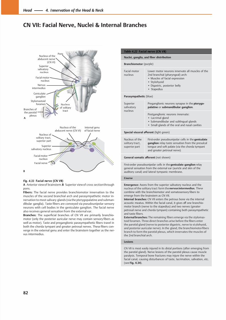
8/15/2019 Head and Neck Anatomy for Dental Medicine - Thieme; (January 26, 2010)
http://slidepdf.com/reader/full/head-and-neck-anatomy-for-dental-medicine-thieme-january-26-2010 95/384
Nervusintermedius
Stylomastoidforamen
Geniculateganglion
Nucleusof solitary
tract
Pons
Nucleus of theabducent nerve
(CN VI)
Superiorsalivatory
nucleus
Facial motornucleus
Branches of
the parotidplexus
A
Facial motornucleus
Nucleus of solitary tract,superior part
Superiorsalivatory nucleus
Nucleus of theabducent nerve (CN VI)
B
Internal genuof facial nerve
Facial nerve
Table 4.22 Facial nerve (CN VII)
Nuclei, ganglia, and fiber distribution
Branchiomotor (purple)
Facial motor
nucleus
Lower motor neurons innervate all muscles of the
2nd branchial (pharyngeal) arch:
• Muscles of facial expression
• Stylohyoid
• Digastric, posterior belly
• Stapedius
Parasympathetic (blue)
Superior
salivatory
nucleus
Preganglionic neurons synapse in the pterygo-
palatine or submandibular ganglion.
Postganglionic neurons innervate:
• Lacrimal gland
• Submandibular and sublingual glands
• Small glands of the oral and nasal cavities
Special visceral aff erent (light green)
Nucleus of the
solitary tract,
superior part
First-order pseudounipolar cells in the geniculate
ganglion relay taste sensation from the presulcal
tongue and soft palate (via the chorda tympani
and greater petrosal nerve).
General somatic aff erent (not shown)
First-order pseudounipolar cells in the geniculate ganglion relay
general sensation from the external ear (auricle and skin of theauditory canal) and lateral tympanic membrane.
Course
Emergence: Axons from the superior salivatory nucleus and the
nucleus of the solitary tract form the nervus intermedius. These
combine with the branchiomotor and somatosensory fibers to
emerge from the brainstem as CN VII.
Internal branches: CN VII enters the petrous bone via the internal
acoustic meatus. Within the facial canal, it gives off one branchio-
motor branch (nerve to the stapedius) and two nerves (greater
petrosal nerve and chorda tympani) containing both parasympathetic
and taste fibers.
External branches: The remaining fibers emerge via the stylomas-
toid foramen. Three direct branches arise before the fibers enter
the parotid gland (nerve to posterior digastric, nerve to st ylohyoid,and posterior auricular nerve). In the gland, the branchiomotor fibers
branch to form the parotid plexus, which innervates the muscles of
the 2nd branchial arch.
Lesions
CN VII is most easily injured in its distal portions (after emerging from
the parotid gland). Nerve lesions of the parotid plexus cause muscle
paralysis. Temporal bone fractures may injure the nerve within the
facial canal, causing disturbances of taste, lacrimation, salivation, etc.
(see Fig. 4.34).
Fig. 4.33 Facial nerve (CN VII)
A Anterior view of brainstem.B Superior view of cross section through
pons.
Fibers: The facial nerve provides branchiomotor innervation to the
muscles of the second branchial arch and parasympathetic motor in-
nervation to most salivary glands (via the pterygopalatine and subman-
dibular ganglia). Taste fibers are conveyed via pseudounipolar sensory
neurons with cell bodies in the geniculate ganglion. The facial nerve
also receives general sensation from the external ear.
Branches: The superficial branches of CN VII are primarily branchio-
motor (only the posterior auricular nerve may contain sensory fibers as
well as motor). Taste and preganglionic parasympatheticfi
bers travel inboth the chorda tympani and greater petrosal nerves. These fibers con-
verge in the external genu and enter the brainstem together as the ner-
vus intermedius.
82
Head 4. Innervation of the Head & Neck
CN VII: Facial Nerve, Nuclei & Internal Branches
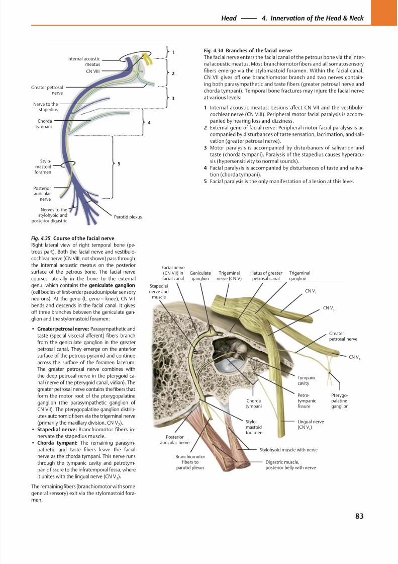
8/15/2019 Head and Neck Anatomy for Dental Medicine - Thieme; (January 26, 2010)
http://slidepdf.com/reader/full/head-and-neck-anatomy-for-dental-medicine-thieme-january-26-2010 96/384
Posteriorauricular nerve
Stapedialnerve and
muscle
Facial nerve(CN VII) infacial canal
Geniculateganglion
Chordatympani
Greaterpetrosal nerve
CN V3
CN V2
CN V1
Trigeminalganglion
Trigeminalnerve (CN V)
Stylohyoid muscle with nerve
Pterygo-palatineganglion
Tympaniccavity
Hiatus of greaterpetrosal canal
Petro-tympanicfissure
Lingual nerve(CN V
3)
Digastric muscle,posterior belly with nerve
Stylo-mastoidforamen
Branchiomotorfibers to
parotid plexus
CN VIII
Stylo-mastoidforamen
Posteriorauricular
nerve
Greater petrosalnerve
Internal acousticmeatus
1
2
3
4
5
Chordatympani
Nerve to thestapedius
Nerves to thestylohyoid and
posterior digastricParotid plexus
Fig. 4.34 Branches of the facial nerve
The facial nerve enters the facial canal of the petrous bone via the inter-
nal acoustic meatus. Most branchiomotorfibers and all somatosensory
fibers emerge via the stylomastoid foramen. Within the facial canal,
CN VII gives off one branchiomotor branch and two nerves contain-
ing both parasympathetic and taste fibers (greater petrosal nerve and
chorda tympani). Temporal bone fractures may injure the facial nerve
at various levels:
1 Internal acoustic meatus: Lesions aff ect CN VII and the vestibulo-
cochlear nerve (CN VIII). Peripheral motor facial paralysis is accom-
panied by hearing loss and dizziness.
2 External genu of facial nerve: Peripheral motor facial paralysis is ac-
companied by disturbances of taste sensation, lacrimation, and sali-
vation (greater petrosal nerve).
3 Motor paralysis is accompanied by disturbances of salivation and
taste (chorda tympani). Paralysis of the stapedius causes hyperacu-
sis (hypersensitivity to normal sounds).
4 Facial paralysis is accompanied by disturbances of taste and saliva-
tion (chorda tympani).
5 Facial paralysis is the only manifestation of a lesion at this level.
Fig. 4.35 Course of the facial nerve
Right lateral view of right temporal bone (pe-
trous part). Both the facial nerve and vestibulo-
cochlear nerve (CN VIII, not shown) pass through
the internal acoustic meatus on the posterior
surface of the petrous bone. The facial nerve
courses laterally in the bone to the external
genu, which contains the geniculate ganglion
(cell bodies of first-order pseudounipolar sensory
neurons). At the genu (L. genu = knee), CN VII
bends and descends in the facial canal. It gives
off three branches between the geniculate gan-
glion and the stylomastoid foramen:
• Greater petrosal nerve: Parasympathetic and
taste (special visceral aff erent) fibers branch
from the geniculate ganglion in the greater
petrosal canal. They emerge on the anterior
surface of the petrous pyramid and continue
across the surface of the foramen lacerum.
The greater petrosal nerve combines with
the deep petrosal nerve in the pterygoid ca-
nal (nerve of the pterygoid canal, vidian). The
greater petrosal nerve contains the fibers that
form the motor root of the pterygopalatineganglion (the parasympathetic ganglion of
CN VII). The pterygopalatine ganglion distrib-
utes autonomic fibers via the trigeminal nerve
(primarily the maxillary division, CN V2).
• Stapedial nerve: Branchiomotor fibers in-
nervate the stapedius muscle.
• Chorda tympani: The remaining parasym-
pathetic and taste fibers leave the facial
nerve as the chorda tympani. This nerve runs
through the tympanic cavity and petrotym-
panic fissure to the infratemporal fossa, where
it unites with the lingual nerve (CN V3).
The remainingfibers (branchiomotor with some
general sensory) exit via the stylomastoid fora-men.
83
Head 4. Innervation of the Head & Neck
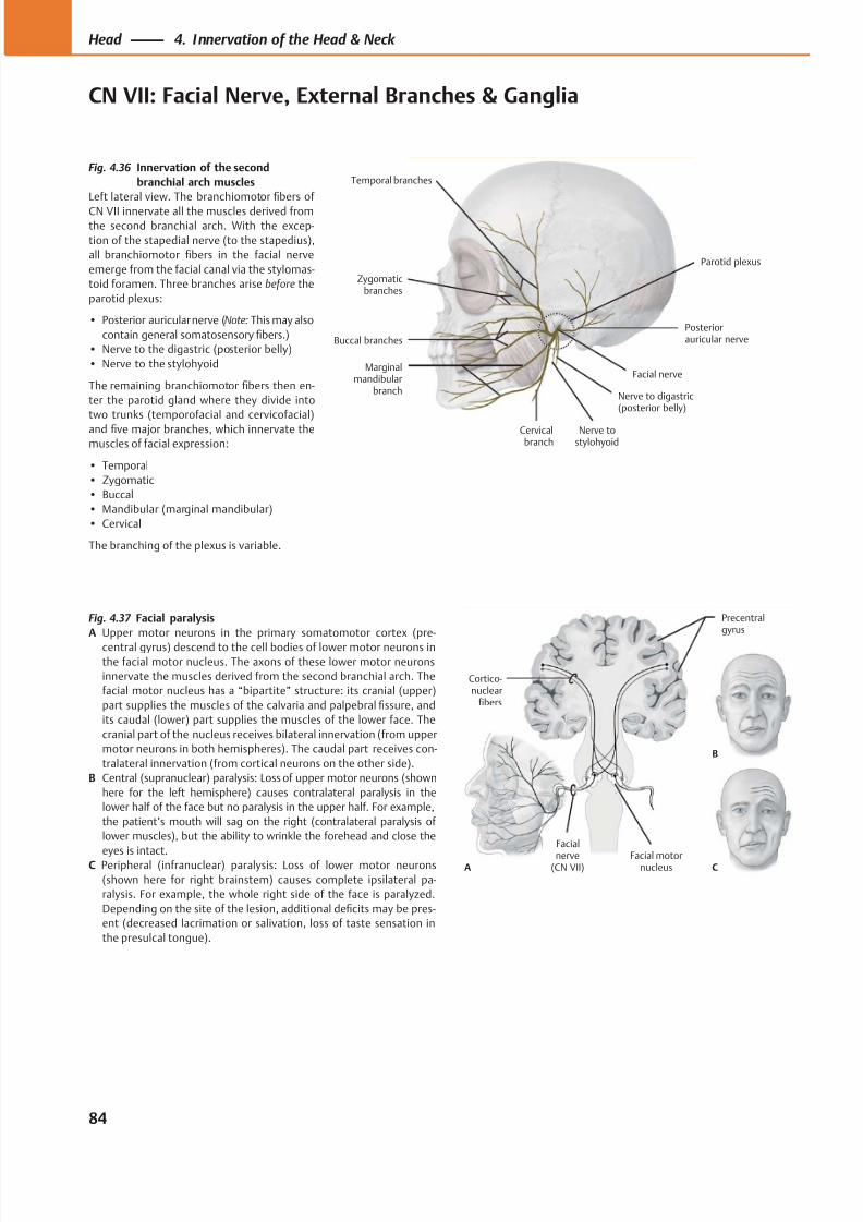
8/15/2019 Head and Neck Anatomy for Dental Medicine - Thieme; (January 26, 2010)
http://slidepdf.com/reader/full/head-and-neck-anatomy-for-dental-medicine-thieme-january-26-2010 97/384
Temporal branches
Zygomaticbranches
Buccal branches
Marginalmandibular
branch
Cervicalbranch
Nerve to digastric(posterior belly)
Parotid plexus
Posteriorauricular nerve
Facial nerve
Nerve tostylohyoid
A C
B
Cortico-nuclear
fibers
Precentralgyrus
Facial motornucleus
Facial
nerve(CN VII)
Fig. 4.36 Innervation of the second
branchial arch muscles
Left lateral view. The branchiomotor fibers of
CN VII innervate all the muscles derived fromthe second branchial arch. With the excep-
tion of the stapedial nerve (to the stapedius),
all branchiomotor fibers in the facial nerve
emerge from the facial canal via the stylomas-
toid foramen. Three branches arise before the
parotid plexus:
• Posterior auricular nerve (Note: This may also
contain general somatosensory fibers.)
• Nerve to the digastric (posterior belly)
• Nerve to the stylohyoid
The remaining branchiomotor fibers then en-
ter the parotid gland where they divide into
two trunks (temporofacial and cervicofacial)
and five major branches, which innervate themuscles of facial expression:
• Temporal
• Zygomatic
• Buccal
• Mandibular (marginal mandibular)
• Cervical
The branching of the plexus is variable.
Fig. 4.37 Facial paralysis
A Upper motor neurons in the primary somatomotor cortex (pre-
central gyrus) descend to the cell bodies of lower motor neurons in
the facial motor nucleus. The axons of these lower motor neurons
innervate the muscles derived from the second branchial arch. The
facial motor nucleus has a “bipartite” structure: its cranial (upper)
part supplies the muscles of the calvaria and palpebral fissure, and
its caudal (lower) part supplies the muscles of the lower face. The
cranial part of the nucleus receives bilateral innervation (from upper
motor neurons in both hemispheres). The caudal part receives con-
tralateral innervation (from cortical neurons on the other side).
B Central (supranuclear) paralysis: Loss of upper motor neurons (shown
here for the left hemisphere) causes contralateral paralysis in the
lower half of the face but no paralysis in the upper half. For example,
the patient’s mouth will sag on the right (contralateral paralysis of
lower muscles), but the ability to wrinkle the forehead and close the
eyes is intact.C Peripheral (infranuclear) paralysis: Loss of lower motor neurons
(shown here for right brainstem) causes complete ipsilateral pa-
ralysis. For example, the whole right side of the face is paralyzed.
Depending on the site of the lesion, additional deficits may be pres-
ent (decreased lacrimation or salivation, loss of taste sensation in
the presulcal tongue).
84
Head 4. Innervation of the Head & Neck
CN VII: Facial Nerve, External Branches & Ganglia
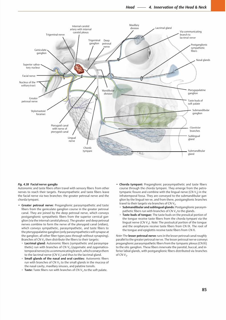
8/15/2019 Head and Neck Anatomy for Dental Medicine - Thieme; (January 26, 2010)
http://slidepdf.com/reader/full/head-and-neck-anatomy-for-dental-medicine-thieme-january-26-2010 98/384
Submandibularganglion
Via communicatingbranch tolacrimal nerve
Greaterpetrosal nerve
Pterygopalatineganglion
Nucleus of thesolitary tract
Geniculateganglion
Trigeminal nerve
Facial nerve
Lingualnerve
Sublingualgland
Submandibulargland
Nasal glands
Lacrimal glandMaxillarydivision
Postganglionicsympatheticfibers
Pterygoid canalwith nerve of
pterygoid canal
Glandularbranches
Chordatympani
Stylomastoidforamen
Internal carotidartery with internal
carotid plexus
Mandibulardivision
Superior saliva-tory nucleus
Deeppetrosal
nerve
Trigeminalganglion
Taste buds of soft palate
Fig. 4.38 Facial nerve ganglia
Greater petrosal nerve:
-
2
Lacrimal gland: -
2
1
Small glands of the nasal and oral cavities:
2
Taste: 2
Chorda tympani:
-
3
-
3
Submandibular and sublingual glands: -
3
Taste buds of tongue:
3 Note:
Note: lesser petrosal nerve
-
3
85
Head 4. Innervation of the Head & Neck
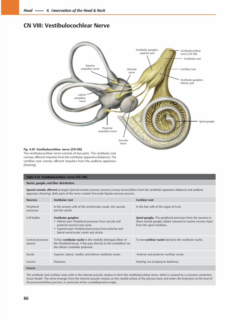
8/15/2019 Head and Neck Anatomy for Dental Medicine - Thieme; (January 26, 2010)
http://slidepdf.com/reader/full/head-and-neck-anatomy-for-dental-medicine-thieme-january-26-2010 99/384
Vestibular ganglion,superior part
Cochlear root
Spiral ganglia
Vestibular root
Saccularnerve
Utricularnerve
Posteriorampullary nerve
Anteriorampullary nerve
Vestibulocochlearnerve (CN VIII)
Vestibular ganglion,inferior part
Lateralampullary
nerve
Table 4.23 Vestibulocochlear nerve (CN VIII)
Nuclei, ganglia, and fiber distribution
Special somatic aff erent (orange): Special somatic sensory neurons convey sensory fibers from the vestibular apparatus (balance) and auditory
apparatus (hearing). Both parts of the nerve contain first-order bipolar sensory neurons.
Neurons Vestibular root Cochlear root
Peripheral
processes
In the sensory cells of the semicircular canals, the saccule,
and the utricle.
In the hair cells of the organ of Corti.
Cell bodies Vestibular ganglion
• Inferior part: Peripheral processes from saccule and
posterior semicircular canal.
• Superior part: Peripheral processes from anterior andlateral semicircular canals and utricle.
Spiral ganglia. The peripheral processes from the neurons in
these myriad ganglia radiate outward to receive sensory input
from the spiral modiolus.
Central processes
(axons)
To four vestibular nuclei in the medulla oblongata (floor of
the rhomboid fossa). A few pass directly to the cerebellum via
the inferior cerebellar peduncle.
To two cochlear nuclei lateral to the vestibular nuclei.
Nuclei Superior, lateral, medial, and inferior vestibular nuclei. Anterior and posterior cochlear nuclei.
Lesions Dizziness. Hearing loss (ranging to deafness).
Course
The vestibular and cochlear roots unite in the internal acoustic meatus to form the vestibulocochlear nerve, which is covered by a common connective
tissue sheath. The nerve emerges from the internal acoustic meatus on the medial surface of the petrous bone and enters the brainstem at the level of
the pontomedullary junction, in particular at the cerebellopontine angle.
Fig. 4.39 Vestibulocochlear nerve (CN VIII)
The vestibulocochlear nerve consists of two parts. The vestibular root
conveys aff erent impulses from the vestibular apparatus (balance). The
cochlear root conveys aff erent impulses from the auditory apparatus
(hearing).
86
Head 4. Innervation of the Head & Neck
CN VIII: Vestibulocochlear Nerve
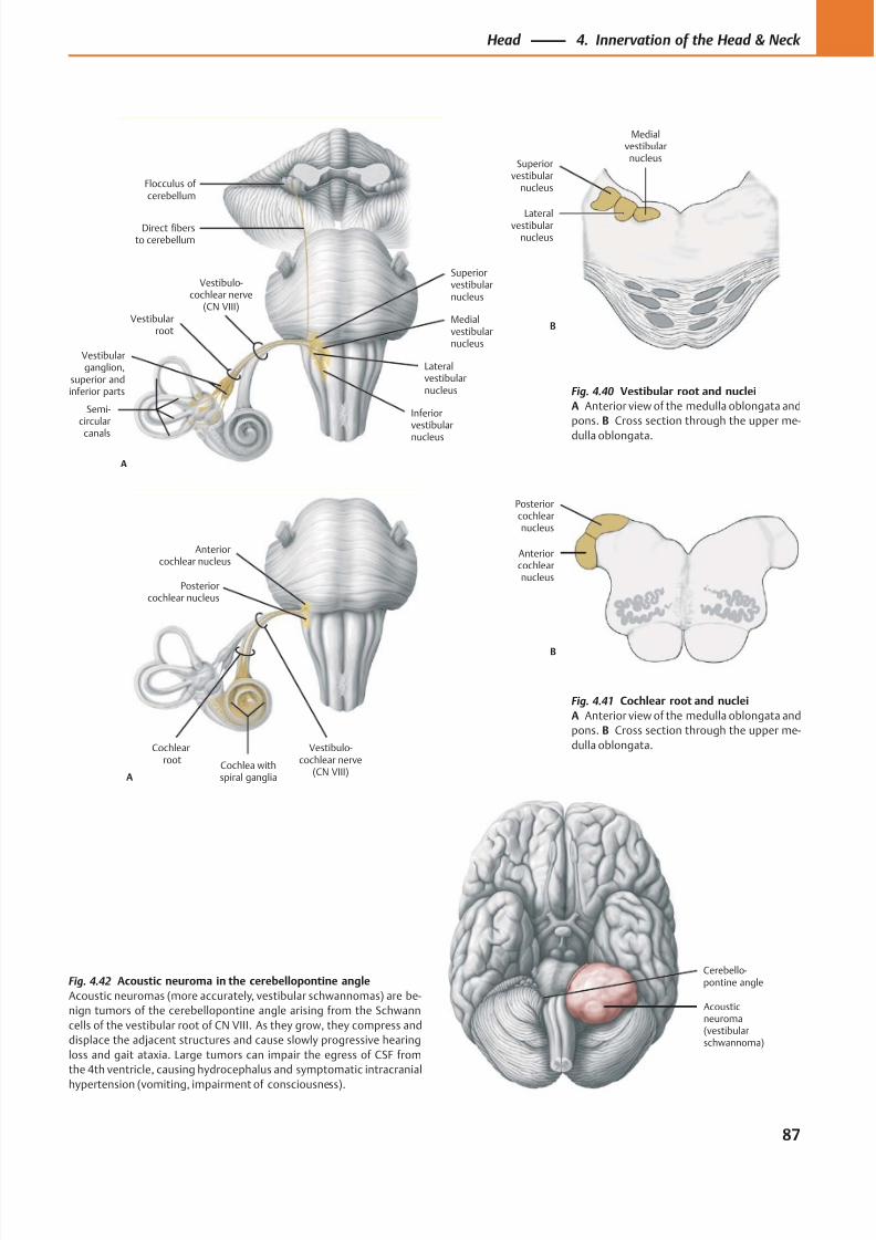
8/15/2019 Head and Neck Anatomy for Dental Medicine - Thieme; (January 26, 2010)
http://slidepdf.com/reader/full/head-and-neck-anatomy-for-dental-medicine-thieme-january-26-2010 100/384
Cerebello-pontine angle
Acousticneuroma(vestibularschwannoma)
Medialvestibularnucleus
Lateralvestibularnucleus
Superiorvestibular
nucleus
B
Anteriorcochlearnucleus
Posteriorcochlearnucleus
B
Flocculus of cerebellum
Inferiorvestibular
nucleus
Medialvestibularnucleus
Lateralvestibularnucleus
Superiorvestibularnucleus
Vestibulo-cochlear nerve
(CN VIII)
A
Semi-circular
canals
Vestibularganglion,
superior andinferior parts
Vestibularroot
Direct fibersto cerebellum
Posteriorcochlear nucleus
Anteriorcochlear nucleus
A
Vestibulo-cochlear nerve
(CN VIII)
Cochlearroot
Cochlea withspiral ganglia
Fig. 4.41 Cochlear root and nuclei
A Anterior view of the medulla oblongata and
pons. B Cross section through the upper me-
dulla oblongata.
Fig. 4.42 Acoustic neuroma in the cerebellopontine angle
Acoustic neuromas (more accurately, vestibular schwannomas) are be-
nign tumors of the cerebellopontine angle arising from the Schwann
cells of the vestibular root of CN VIII. As they grow, they compress and
displace the adjacent structures and cause slowly progressive hearing
loss and gait ataxia. Large tumors can impair the egress of CSF from
the 4th ventricle, causing hydrocephalus and symptomatic intracranial
hypertension (vomiting, impairment of consciousness).
Fig. 4.40 Vestibular root and nuclei
A Anterior view of the medulla oblongata and
pons. B Cross section through the upper me-
dulla oblongata.
87
Head 4. Innervation of the Head & Neck
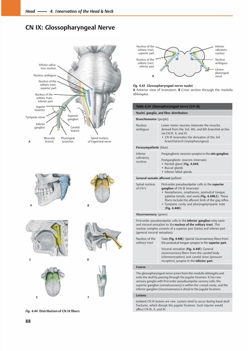
8/15/2019 Head and Neck Anatomy for Dental Medicine - Thieme; (January 26, 2010)
http://slidepdf.com/reader/full/head-and-neck-anatomy-for-dental-medicine-thieme-january-26-2010 101/384
Nucleus of thesolitary tract,
inferior part
Jugularforamen
Pharyngealbranches
Carotidbranch
Muscularbranch
Tympanic nerve
Inferiorganglion
Superiorganglion
Nucleus of thesolitary tract,superior part
Nucleus ambiguus
Inferior saliva-tory nucleus
ASpinal nucleus
of trigeminal nerve
Nucleusambiguus
Nucleus of thesolitary tract,
inferior part
Inferiorsalivatorynucleus
B
Nucleus of thesolitary tract,superior part
Glosso-pharyngealnerve
A
FE
B
C D
Table 4.24 Glossopharyngeal nerve (CN IX)
Nuclei, ganglia, and fiber distribution
Branchiomotor (purple)
Nucleus
ambiguus
Lower motor neurons innervate the muscles
derived from the 3rd, 4th, and 6th branchial arches
via CN IX, X, and XI.
• CN IX innervates the derivative of the 3rd
branchial arch (stylopharyngeus)
Parasympathetic (blue)
Inferior
salivatory
nucleus
Preganglionic neurons synapse in the otic ganglion.
Postganglionic neurons innervate:
• Parotid gland (Fig. 4.44A)
• Buccal glands
• Inferior labial glands
General somatic aff erent (yellow)
Spinal nucleusof CN V
First-order pseudounipolar cells in the superiorganglion of CN IX innervate:
• Nasopharynx, oropharynx, postsulcal tongue,
palatine tonsils, and uvula (Fig. 4.44B,C). These
fibers include the aff erent limb of the gag reflex.
• Tympanic cavity and pharyngotympanic tube
(Fig. 4.44D).
Viscerosensory (green)
First-order pseudounipolar cells in the inferior ganglion relay taste
and visceral sensation to the nucleus of the solitary tract. This
nuclear complex consists of a superior part (taste) and inferior part
(general visceral sensation).
Nucleus of the
solitary tract
Taste (Fig. 4.44E): Special viscerosensory fibers from
the postsulcal tongue synapse in the superior part.
Visceral sensation (Fig. 4.44F): General
viscerosensory fibers from the carotid body
(chemoreceptors) and carotid sinus (pressure
receptors) synapse in the inferior part.
Course
The glossopharyngeal nerve arises from the medulla oblongata and
exits the skull by passing through the jugular foramen. It has two
sensory ganglia with first-order pseudounipolar sensory cells: the
superior ganglion (somatosensory) is within the cranial cavity, and the
inferior ganglion (viscerosensory) is distal to the jugular foramen.
Lesions
Isolated CN IX lesions are rare. Lesions tend to occur during basal skull
fractures, which disrupt the jugular foramen. Such injuries would
aff ect CN IX, X, and XI.
Fig. 4.43 Glossopharyngeal nerve nuclei
A Anterior view of brainstem. B Cross section through the medulla
oblongata.
Fig. 4.44 Distribution of CN IX fibers
88
Head 4. Innervation of the Head & Neck
CN IX: Glossopharyngeal Nerve
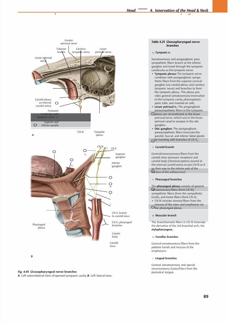
8/15/2019 Head and Neck Anatomy for Dental Medicine - Thieme; (January 26, 2010)
http://slidepdf.com/reader/full/head-and-neck-anatomy-for-dental-medicine-thieme-january-26-2010 102/384
Carotidbody
CN IX
Inferiorganglion
Superiorganglion
CN X
CN X, branchto carotid sinus
CN X, pharyngeal
branches
Pharyngeal
plexus
B
LTy
To
M
C
P
Carotidsinus
Tubarianbranch
Carotid plexuson internal
carotid artery
CN IX
Tympanic
canaliculus withtympanic nerve
Tympanicplexus
Lesser petrosalnerve
Carotico-tympanic nerve
Superior andinferior ganglia
Ty
Lesserpetrosal nerve
A
Greaterpetrosal nerve
Table 4.25 Glossopharyngeal nervebranches
Ty Tympanic n.
Somatosensory and preganglionic para-
sympathetic fibers branch at the inferior
ganglion and travel through the tympanic
canaliculus as the tympanic nerve.
• Tympanic plexus: The tympanic nerve
combines with postganglionic sympa-
thetic fibers from the superior cervical
ganglion (via carotid plexus and carotico-
tympanic nerve) and branches to form
the tympanic plexus. This plexus pro-
vides general somatosensory innervation
to the t ympanic cavity, pharyngotym-
panic tube, and mastoid air cells.
• Lesser petrosal n.: The preganglionic
parasympathetic fibers in the t ympanic
plexus are reconstituted as the lesserpetrosal nerve, which runs in the lesser
petrosal canal to synapse in the otic
ganglion.
• Otic ganglion: The postganglionic
parasympathetic fibers innervate the
parotid, buccal, and inferior labial glands
by traveling with branches of CN V3.
C Carotid branch
General viscerosensory fibers from the
carotid sinus (pressure receptors) and
carotid body (chemoreceptors) ascend on
the internal carotid artery to join CN IX or X
on their way to the inferior part of the
nucleus of the solitary tract.
P Pharyngeal branches
The pharyngeal plexus consists of general
somatosensory fibers (from CN IX),
sympathetic fibers (from the sympathetic
trunk), and motor fibers (from CN X).
• CN IX receives sensory fibers from the
mucosa of the naso- and oropharynx via
the pharyngeal plexus.
M Muscular branch
The branchiomotor fibers in CN IX innervate
the derivative of the 3rd branchial arch, thestylopharyngeus .
To Tonsillar branches
General somatosensory fibers from the
palatine tonsils and mucosa of the
oropharynx.
L Lingual branches
General somatosensory and special
viscerosensory (taste) fibers from the
postsulcal tongue.Fig. 4.45 Glossopharyngeal nerve branches
A Left anterolateral view of opened tympanic cavity. B Left lateral view.
89
Head 4. Innervation of the Head & Neck
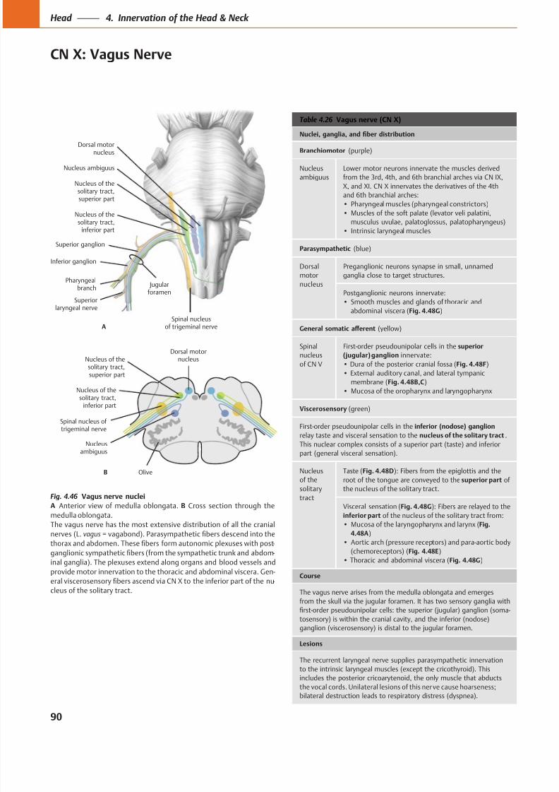
8/15/2019 Head and Neck Anatomy for Dental Medicine - Thieme; (January 26, 2010)
http://slidepdf.com/reader/full/head-and-neck-anatomy-for-dental-medicine-thieme-january-26-2010 103/384
Spinal nucleusof trigeminal nerve
Dorsal motornucleus
Superiorlaryngeal nerve
Pharyngealbranch
Inferior ganglion
Nucleus ambiguus
Jugularforamen
Superior ganglion
Nucleus of thesolitary tract,superior part
A
Nucleus of thesolitary tract,
inferior part
Spinal nucleus of trigeminal nerve
Nucleus of thesolitary tract,
inferior part
Dorsal motornucleus
B
Nucleus of thesolitary tract,superior part
Nucleusambiguus
Olive
Table 4.26 Vagus nerve (CN X)
(purple)
Nucleus
ambiguus
Lower motor neurons innervate the muscles derived
from the 3rd, 4th, and 6th branchial arches via CN IX,
X, and XI. CN X innervates the derivatives of the 4th
and 6th branchial arches:
(blue)
Dorsal
motornucleus
ganglia close to target structures.
abdominal viscera (Fig. 4.48G)
nucleus
of CN V
First-order pseudounipolar cells in the
innervate:
Fig. 4.48F)
membrane (Fig. 4.48B,C)
(green)
First-order pseudounipolar cells in the
.
part (general visceral sensation).
Nucleus
of the
tract
Taste (Fig. 4.48D): Fibers from the epiglottis and the
of
Visceral sensation (Fig. 4.48G
Fig.
4.48A)
(chemoreceptors) (Fig. 4.48E) Fig. 4.48G)
The vagus nerve arises from the medulla oblongata and emerges
-
the vocal cords. Unilateral lesions of this nerve cause hoarseness;
Fig. 4.46 Vagus nerve nuclei
A B Cross section through the
medulla oblongata.
nerves (L. vagus
-
-
provide motor innervation to the thoracic and abdominal viscera. Gen-
-
90
Head 4. Innervation of the Head & Neck
CN X: Vagus Nerve
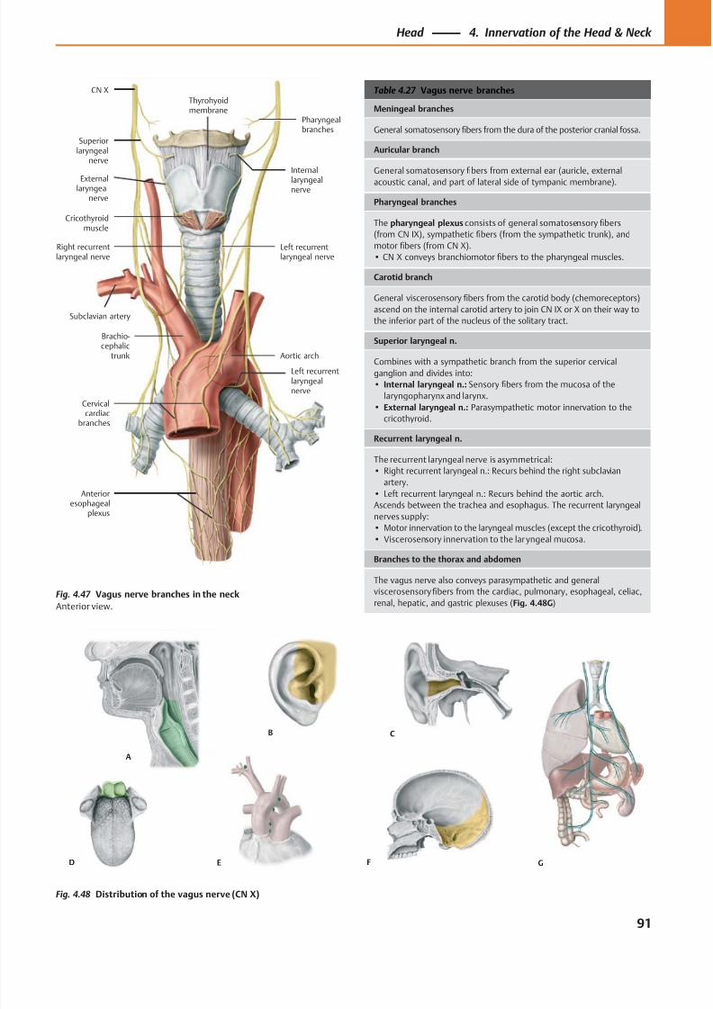
8/15/2019 Head and Neck Anatomy for Dental Medicine - Thieme; (January 26, 2010)
http://slidepdf.com/reader/full/head-and-neck-anatomy-for-dental-medicine-thieme-january-26-2010 104/384
A
F
B C
E GD
Left recurrentlaryngealnerve
Left recurrentlaryngeal nerve
Thyrohyoidmembrane
CN X
Internallaryngealnerve
Pharyngealbranches
Subclavian artery
Cricothyroidmuscle
Cervicalcardiac
branches
Aortic arch
Brachio-cephalic
trunk
Right recurrentlaryngeal nerve
Superiorlaryngeal
nerve
Externallaryngeal
nerve
Anterioresophageal
plexus
Table 4.27 Vagus nerve branches
Meningeal branches
General somatosensory fibers from the dura of the posterior cranial fossa.
Auricular branch
General somatosensory fibers from external ear (auricle, external
acoustic canal, and part of lateral side of tympanic membrane).
Pharyngeal branches
The pharyngeal plexus consists of general somatosensory fibers
(from CN IX), sympathetic fibers (from the sympathetic trunk), and
motor fibers (from CN X).
• CN X conveys branchiomotor fibers to the pharyngeal muscles.
Carotid branch
General viscerosensory fibers from the carotid body (chemoreceptors)
ascend on the internal carotid artery to join CN IX or X on their way to
the inferior part of the nucleus of the solitary tract.
Superior laryngeal n.
Combines with a sympathetic branch from the superior cervical
ganglion and divides into:
• Internal laryngeal n.: Sensory fibers from the mucosa of the
laryngopharynx and larynx.
• External laryngeal n.: Parasympathetic motor innervation to the
cricothyroid.
Recurrent laryngeal n.
The recurrent laryngeal nerve is asymmetrical:
• Right recurrent laryngeal n.: Recurs behind the right subclavian
artery.
• Left recurrent laryngeal n.: Recurs behind the aortic arch.
Ascends between the trachea and esophagus. The recurrent laryngeal
nerves supply:
• Motor innervation to the laryngeal muscles (except the cricothyroid).• Viscerosensory innervation to the laryngeal mucosa.
Branches to the thorax and abdomen
The vagus nerve also conveys parasympathetic and general
viscerosensory fibers from the cardiac, pulmonary, esophageal, celiac,
renal, hepatic, and gastric plexuses (Fig. 4.48G)
Fig. 4.48 Distribution of the vagus nerve (CN X)
Fig. 4.47 Vagus nerve branches in the neck
Anterior view.
91
Head 4. Innervation of the Head & Neck
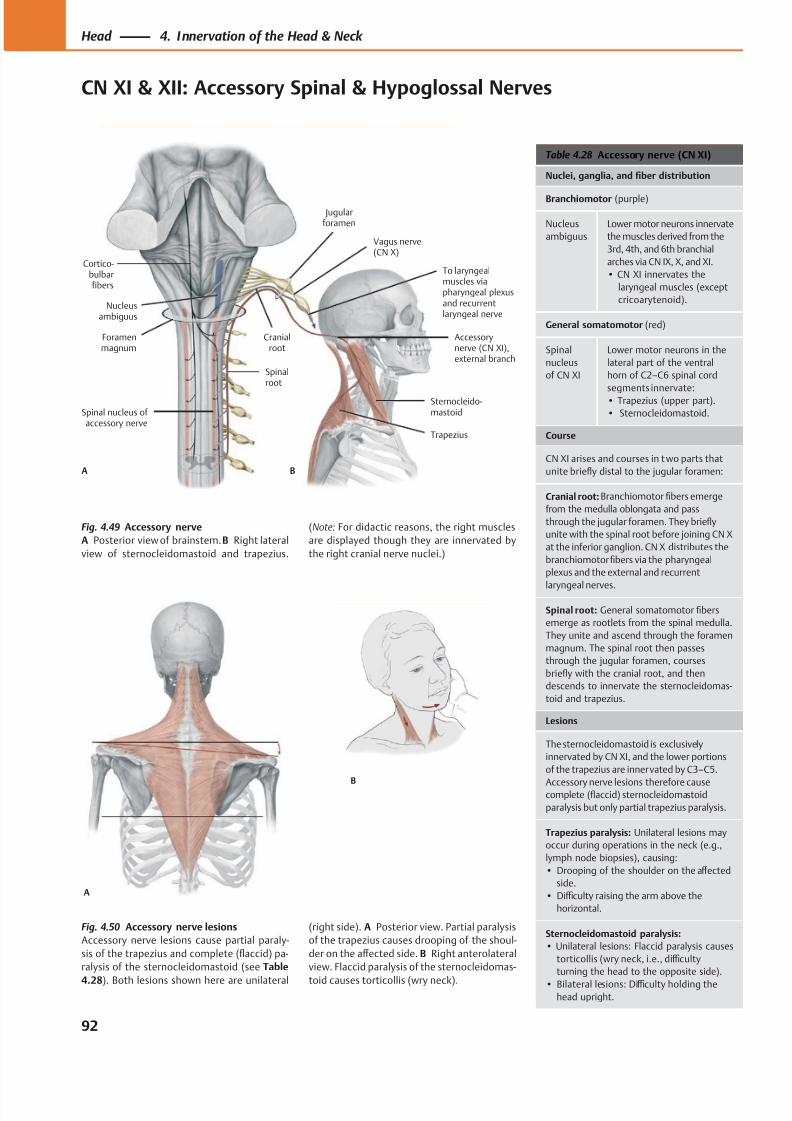
8/15/2019 Head and Neck Anatomy for Dental Medicine - Thieme; (January 26, 2010)
http://slidepdf.com/reader/full/head-and-neck-anatomy-for-dental-medicine-thieme-january-26-2010 105/384
To laryngealmuscles viapharyngeal plexusand recurrentlaryngeal nerve
Trapezius
Cortico-bulbarfibers
Cranialroot
Foramenmagnum
Accessorynerve (CN XI),external branch
Vagus nerve(CN X)
Nucleusambiguus
Sternocleido-mastoid
Jugularforamen
Spinalroot
Spinal nucleus of accessory nerve
A B
A
B
Table 4.28 Accessory nerve (CN XI)
Nuclei, ganglia, and fiber distribution
Branchiomotor (purple)
Nucleus
ambiguus
Lower motor neurons innervate
the muscles derived from the
3rd, 4th, and 6th branchial
arches via CN IX, X, and XI.
• CN XI innervates the
laryngeal muscles (except
cricoarytenoid).
General somatomotor (red)
Spinal
nucleus
of CN XI
Lower motor neurons in the
lateral part of the ventral
horn of C2–C6 spinal cord
segments innervate:• Trapezius (upper part).
• Sternocleidomastoid.
Course
CN XI arises and courses in t wo parts that
unite briefly distal to the jugular foramen:
Cranial root: Branchiomotor fibers emerge
from the medulla oblongata and pass
through the jugular foramen. They briefly
unite with the spinal root before joining CN X
at the inferior ganglion. CN X distributes the
branchiomotorfibers via the pharyngeal
plexus and the external and recurrent
laryngeal nerves.
Spinal root: General somatomotor fibers
emerge as rootlets from the spinal medulla.
They unite and ascend through the foramen
magnum. The spinal root then passes
through the jugular foramen, courses
briefly with the cranial root, and then
descends to innervate the sternocleidomas-
toid and trapezius.
Lesions
The sternocleidomastoid is exclusively
innervated by CN XI, and the lower portions
of the trapezius are innervated by C3–C5.
Accessory nerve lesions therefore causecomplete (flaccid) sternocleidomastoid
paralysis but only partial trapezius paralysis.
Trapezius paralysis: Unilateral lesions may
occur during operations in the neck (e.g.,
lymph node biopsies), causing:
• Drooping of the shoulder on the aff ected
side.
• Diffi culty raising the arm above the
horizontal.
Sternocleidomastoid paralysis:
• Unilateral lesions: Flaccid paralysis causes
torticollis (wry neck, i.e., diffi culty
turning the head to the opposite side).
• Bilateral lesions: Diffi culty holding thehead upright.
Fig. 4.49 Accessory nerve
A Posterior view of brainstem. B Right lateral
view of sternocleidomastoid and trapezius.
Fig. 4.50 Accessory nerve lesions
Accessory nerve lesions cause partial paraly-
sis of the trapezius and complete (flaccid) pa-
ralysis of the sternocleidomastoid (see Table
4.28). Both lesions shown here are unilateral
(Note: For didactic reasons, the right muscles
are displayed though they are innervated by
the right cranial nerve nuclei.)
(right side). A Posterior view. Partial paralysis
of the trapezius causes drooping of the shoul-
der on the aff ected side. B Right anterolateral
view. Flaccid paralysis of the sternocleidomas-
toid causes torticollis (wry neck).
92
Head 4. Innervation of the Head & Neck
CN XI & XII: Accessory Spinal & Hypoglossal Nerves
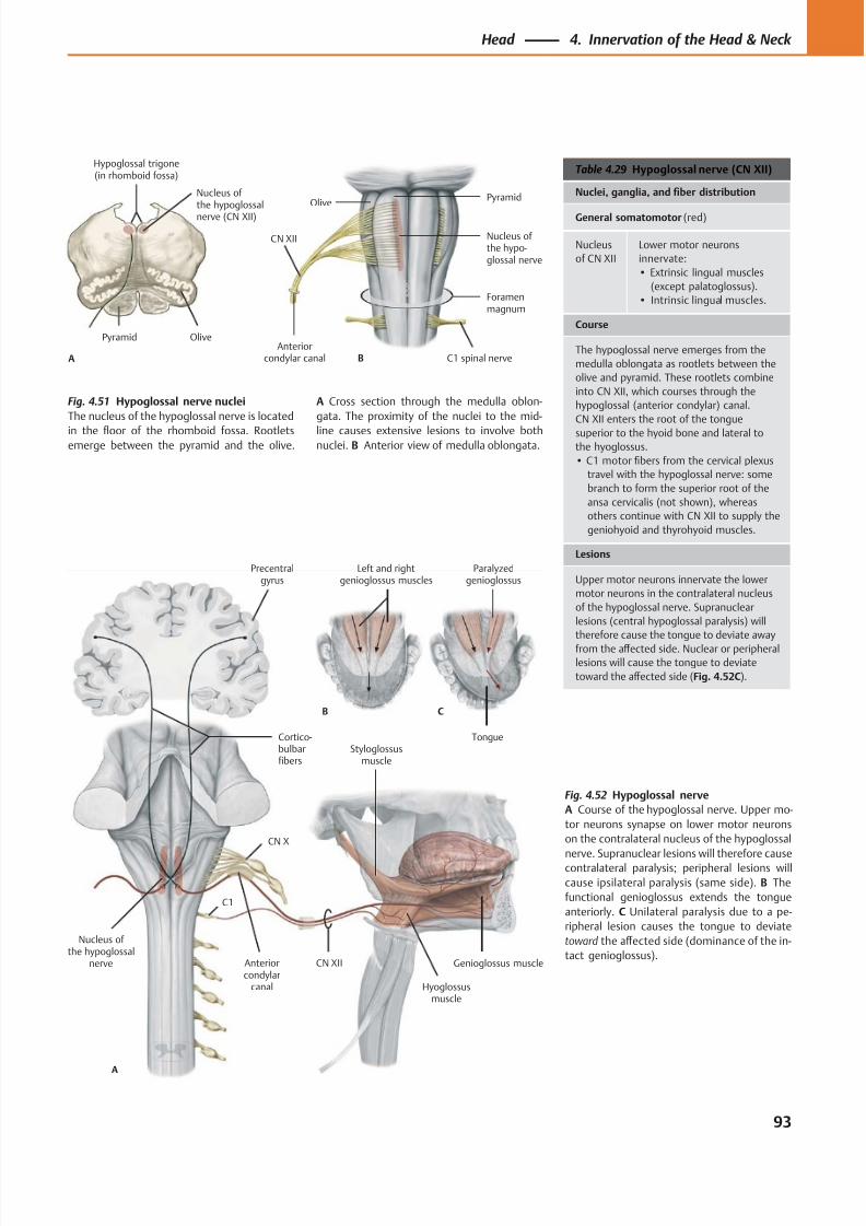
8/15/2019 Head and Neck Anatomy for Dental Medicine - Thieme; (January 26, 2010)
http://slidepdf.com/reader/full/head-and-neck-anatomy-for-dental-medicine-thieme-january-26-2010 106/384
Hypoglossal trigone(in rhomboid fossa)
Nucleus of the hypoglossal
nerve (CN XII)
A
OlivePyramid
Foramenmagnum
C1 spinal nerve
CN XII
Anteriorcondylar canal
Nucleus of the hypo-glossal nerve
B
OlivePyramid
CN XII
Hyoglossusmuscle
Cortico-bulbarfibers
Styloglossusmuscle
Anteriorcondylar
canal
Nucleus of the hypoglossal
nerve
A
B C
Precentralgyrus
Left and rightgenioglossus muscles
Paralyzedgenioglossus
Tongue
CN X
C1
Genioglossus muscle
Table 4.29 Hypoglossal nerve (CN XII)
Nuclei, ganglia, and fiber distribution
General somatomotor (red)
Nucleus
of CN XII
Lower motor neurons
innervate:
• Extrinsic lingual muscles
(except palatoglossus).
• Intrinsic lingual muscles.
Course
The hypoglossal nerve emerges from the
medulla oblongata as rootlets between the
olive and pyramid. These rootlets combine
into CN XII, which courses through the
hypoglossal (anterior condylar) canal.
CN XII enters the root of the tongue
superior to the hyoid bone and lateral tothe hyoglossus.
• C1 motor fibers from the cervical plexus
travel with the hypoglossal nerve: some
branch to form the superior root of the
ansa cervicalis (not shown), whereas
others continue with CN XII to supply the
geniohyoid and thyrohyoid muscles.
Lesions
Upper motor neurons innervate the lower
motor neurons in the contralateral nucleus
of the hypoglossal nerve. Supranuclear
lesions (central hypoglossal paralysis) will
therefore cause the tongue to deviate away
from the aff ected side. Nuclear or peripheral
lesions will cause the tongue to deviate
toward the aff ected side (Fig. 4.52C).
Fig. 4.52 Hypoglossal nerve
A Course of the hypoglossal nerve. Upper mo-
tor neurons synapse on lower motor neurons
on the contralateral nucleus of the hypoglossal
nerve. Supranuclear lesions will therefore causecontralateral paralysis; peripheral lesions will
cause ipsilateral paralysis (same side). B The
functional genioglossus extends the tongue
anteriorly. C Unilateral paralysis due to a pe-
ripheral lesion causes the tongue to deviate
toward the aff ected side (dominance of the in-
tact genioglossus).
Fig. 4.51 Hypoglossal nerve nuclei
The nucleus of the hypoglossal nerve is located
in the floor of the rhomboid fossa. Rootletsemerge between the pyramid and the olive.
A Cross section through the medulla oblon-
gata. The proximity of the nuclei to the mid-
line causes extensive lesions to involve bothnuclei. B Anterior view of medulla oblongata.
93
Head 4. Innervation of the Head & Neck
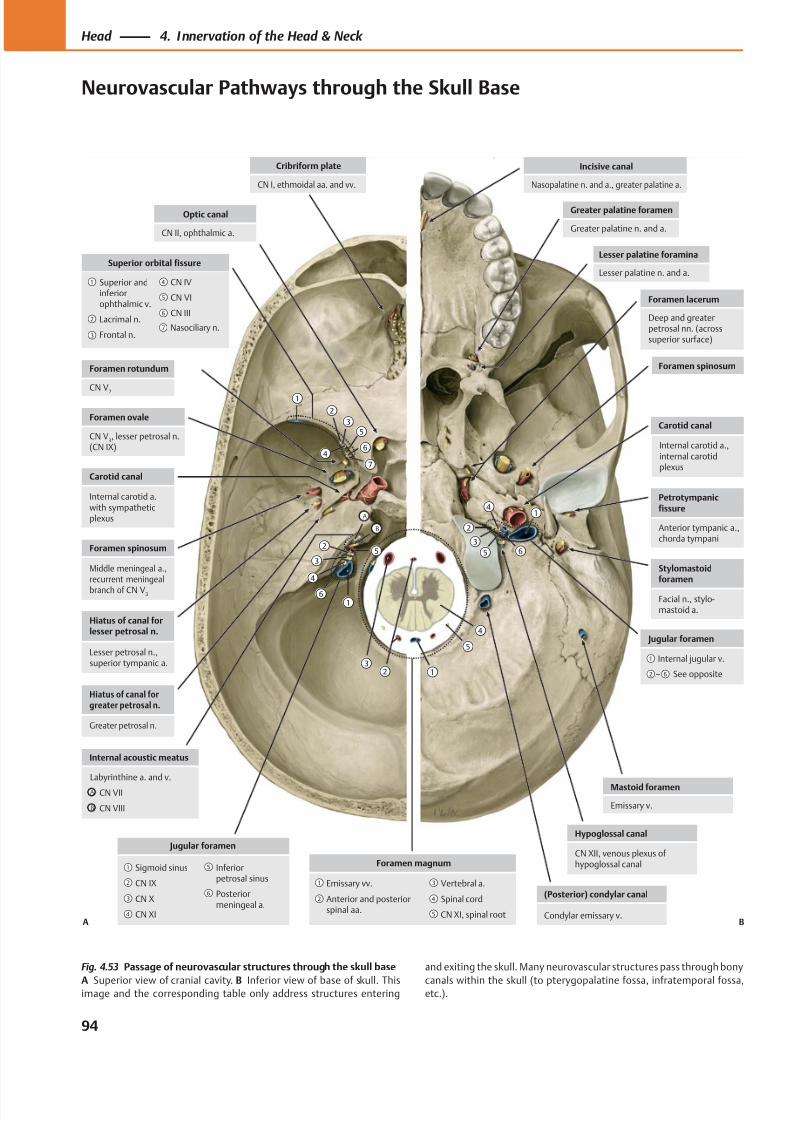
8/15/2019 Head and Neck Anatomy for Dental Medicine - Thieme; (January 26, 2010)
http://slidepdf.com/reader/full/head-and-neck-anatomy-for-dental-medicine-thieme-january-26-2010 107/384
Incisive canal
Nasopalatine n. and a., greater palatine a.
Mastoid foramen
Emissary v.
Hypoglossal canal
CN XII, venous plexus ofhypoglossal canal
(Posterior) condylar canal
Condylar emissary v.
Foramen spinosum
Carotid canal
Petrotympanicfissure
Anterior tympanic a.,chorda tympani
Stylomastoidforamen
Facial n., stylo-mastoid a.
Jugular foramen
– See opposite
Internal jugular v.
Cribriform plate
CN I, ethmoidal aa. and vv.
Internal acoustic meatus
CN VIII
CN VII
Labyrinthine a. and v.
Foramen rotundum
CN V2
Carotid canal
Internal carotid a.with sympatheticplexus
Foramen spinosum
Middle meningeal a.,recurrent meningeal
branch of CN V3
Hiatus of canal forlesser petrosal n.
Lesser petrosal n.,superior tympanic a.
Hiatus of canal forgreater petrosal n.
Greater petrosal n.
Jugular foramen
Posteriormeningeal a.
Inferiorpetrosal sinus
CN XI
CN X
CN IX
Sigmoid sinusForamen magnum
CN XI, spinal root
Spinal cord
Vertebral a.
Anterior and posteriorspinal aa.
Emissary vv.
Optic canal
CN II, ophthalmic a.
Superior orbital fissure
CN III
Frontal n.
Lacrimal n.
Superior andinferiorophthalmic v.
CN VI
CN IV
Foramen ovale
CN V3, lesser petrosal n.
(CN IX)
Foramen lacerum
Deep and greaterpetrosal nn. (acrosssuperior surface)
Greater palatine foramen
Greater palatine n. and a.
Lesser palatine foramina
Lesser palatine n. and a.
A
B
A
B
A B
Internal carotid a.,internal carotidplexus
Nasociliary n.
Fig. 4.53 Passage of neurovascular structures through the skull base
A Superior view of cranial cavity. B Inferior view of base of skull. Thisimage and the corresponding table only address structures entering
and exiting the skull. Many neurovascular structures pass through bony
canals within the skull (to pterygopalatine fossa, infratemporal fossa,etc.).
94
Head 4. Innervation of the Head & Neck
Neurovascular Pathways through the Skull Base
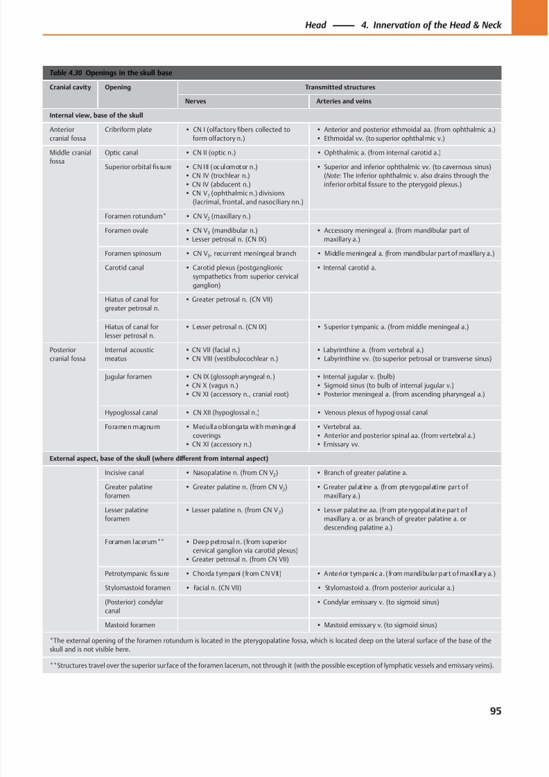
8/15/2019 Head and Neck Anatomy for Dental Medicine - Thieme; (January 26, 2010)
http://slidepdf.com/reader/full/head-and-neck-anatomy-for-dental-medicine-thieme-january-26-2010 108/384
Table 4.30 Openings in the skull base
Cranial cavity Opening Transmitted structures
Nerves Arteries and veins
Internal view, base of the skull
Anterior
cranial fossa
Cribriform plate • CN I (olfactory fibers collected to
form olfactory n.)
• Anterior and posterior ethmoidal aa. (from ophthalmic a.)
• Ethmoidal vv. (to superior ophthalmic v.)
Middle cranial
fossa
Optic canal • CN II (optic n.) • Ophthalmic a. (from internal carotid a.)
Superior orbital fissure • CN III (oculomotor n.)
• CN IV (trochlear n.)
• CN IV (abducent n.)
• CN V1 (ophthalmic n.) divisions
(lacrimal, frontal, and nasociliary nn.)
• Superior and inferior ophthalmic vv. (to cavernous sinus)
(Note: The inferior ophthalmic v. also drains through the
inferior orbital fissure to the pterygoid plexus.)
Foramen rotundum* • CN V2 (maxillary n.)
Foramen ovale • CN V3 (mandibular n.)
• Lesser petrosal n. (CN IX)
• Accessory meningeal a. (from mandibular part of
maxillary a.)
Foramen spinosum • CN V3, recurrent meningeal branch • Middle meningeal a. (from mandibular part of maxillary a.)
Carotid canal • Carotid plexus (postganglionic
sympathetics from superior cervical
ganglion)
• Internal carotid a.
Hiatus of canal for
greater petrosal n.
• Greater petrosal n. (CN VII)
Hiatus of canal for
lesser petrosal n.
• L esser petrosal n. (CN IX) • Superior t ympanic a. (from middle meningeal a.)
Posterior
cranial fossa
Internal acoustic
meatus
• CN VII (facial n.)
• CN VIII (vestibulocochlear n.)
• Labyrinthine a. (from vertebral a.)
• Labyrinthine vv. (to superior petrosal or transverse sinus)
Jugular foramen • CN IX (glossopharyngeal n.)
• CN X (vagus n.)
• CN XI (accessory n., cranial root)
• Internal jugular v. (bulb)
• Sigmoid sinus (to bulb of internal jugular v.)
• Posterior meningeal a. (from ascending pharyngeal a.)
Hypoglossal canal • CN XII (hypoglossal n.) • Venous plexus of hypoglossal canal
Foramen magnum • Medulla oblongata with meningeal
coverings
• CN XI (accessory n.)
• Vertebral aa.
• Anterior and posterior spinal aa. (from vertebral a.)
• Emissary vv.
External aspect, base of the skull (where diff erent from internal aspect)
Incisive canal • Nasopalatine n. (from CN V2) • Branch of greater palatine a.
Greater palatine
foramen
• Greater palatine n. (from CN V2) • Greater palat ine a. (from pterygopalatine part of
maxillary a.)
Lesser palatine
foramen
• Lesser palatine n. (from CN V2) • Lesser palat ine aa. (from pterygopalat ine part of
maxillary a. or as branch of greater palatine a. or
descending palatine a.)
Foramen lacerum** • Deep petrosal n. (from superiorcervical ganglion via carotid plexus)
• Greater petrosal n. (from CN VII)
Petrotympanic fissure • Chorda tympani (from CN VII) • Anterior tympanic a. (from mandibular part of maxillary a.)
Stylomastoid foramen • Facial n. (CN VII) • Stylomastoid a. (from posterior auricular a.)
(Posterior) condylar
canal
• Condylar emissary v. (to sigmoid sinus)
Mastoid foramen • Mastoid emissary v. (to sigmoid sinus)
*The external opening of the foramen rotundum is located in the pterygopalatine fossa, which is located deep on the lateral surface of the base of the
skull and is not visible here.
**Structures travel over the superior surface of the foramen lacerum, not through it (with the possible exception of lymphatic vessels and emissary veins).
95
Head 4. Innervation of the Head & Neck
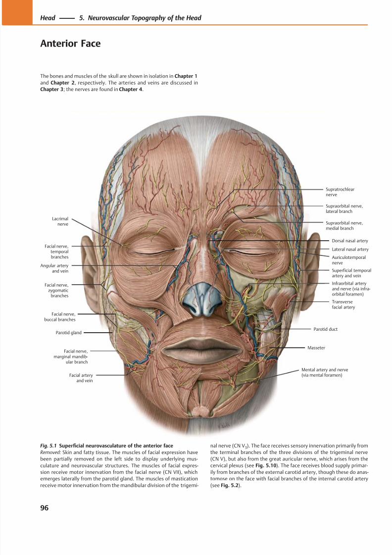
8/15/2019 Head and Neck Anatomy for Dental Medicine - Thieme; (January 26, 2010)
http://slidepdf.com/reader/full/head-and-neck-anatomy-for-dental-medicine-thieme-january-26-2010 109/384
Facial nerve,marginal mandib-
ular branch
Facial nerve,buccal branches
Facial nerve,
zygomaticbranches
Facial nerve,temporalbranches
Lateral nasal artery
Mental artery and nerve(via mental foramen)Facial artery
and vein
Masseter
Parotid ductParotid gland
Transversefacial artery
Infraorbital arteryand nerve (via infra-orbital foramen)
Superficial temporalartery and vein
Auriculotemporalnerve
Angular arteryand vein
Dorsal nasal artery
Supraorbital nerve,medial branch
Supraorbital nerve,lateral branch
Supratrochlear
nerve
Lacrimalnerve
The bones and muscles of the skull are shown in isolation in Chapter 1
and Chapter 2, respectively. The arteries and veins are discussed in
Chapter 3; the nerves are found in Chapter 4.
Fig. 5.1 Superficial neurovasculature of the anterior face
Removed: Skin and fatty tissue. The muscles of facial expression have
been partially removed on the left side to display underlying mus-
culature and neurovascular structures. The muscles of facial expres-
sion receive motor innervation from the facial nerve (CN VII), which
emerges laterally from the parotid gland. The muscles of mastication
receive motor innervation from the mandibular division of the trigemi-
nal nerve (CN V3). The face receives sensory innervation primarily from
the terminal branches of the three divisions of the trigeminal nerve
(CN V), but also from the great auricular nerve, which arises from the
cervical plexus (see Fig. 5.10). The face receives blood supply primar-
ily from branches of the external carotid artery, though these do anas-
tomose on the face with facial branches of the internal carotid artery
(see Fig. 5.2).
96
Head 5. Neurovascular Topography of the Head
Anterior Face
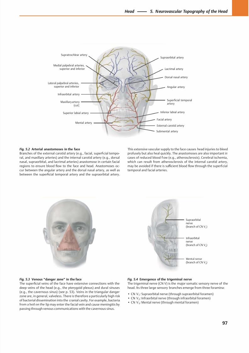
8/15/2019 Head and Neck Anatomy for Dental Medicine - Thieme; (January 26, 2010)
http://slidepdf.com/reader/full/head-and-neck-anatomy-for-dental-medicine-thieme-january-26-2010 110/384
Medial palpebral arteries,superior and inferior
External carotid artery
Superior labial artery Inferior labial artery
Infraorbital artery
Superficial temporalartery
Lateral palpebral arteries,superior and inferior
Lacrimal artery
Supraorbital artery
Dorsal nasal artery
Supratrochlear artery
Maxillary artery(cut)
Mental artery
Angular artery
Facial artery
Submental artery
Mental nerve(branch of CN V
3)
Infraorbitalnerve(branch of CN V
2
)
Supraorbitalnerve(branch of CN V
1)
Fig. 5.2 Arterial anastomoses in the face
Branches of the external carotid artery (e.g., facial, superficial tempo-
ral, and maxillary arteries) and the internal carotid artery (e.g., dorsal
nasal, supraorbital, and lacrimal arteries) anastomose in certain facial
regions to ensure blood flow to the face and head. Anastomoses oc-
cur between the angular artery and the dorsal nasal artery, as well as
between the superficial temporal artery and the supraorbital artery.
Fig. 5.3 Venous “danger zone” in the face
The superficial veins of the face have extensive connections with the
deep veins of the head (e.g., the pterygoid plexus) and dural sinuses
(e.g., the cavernous sinus) (see p. 53). Veins in the triangular danger
zone are, in general, valveless. There is therefore a particularly high risk
of bacterial dissemination into the cranial cavity. For example, bacteria
from a boil on the lip may enter the facial vein and cause meningitis by
passing through venous communications with the cavernous sinus.
Fig. 5.4 Emergence of the trigeminal nerve
The trigeminal nerve (CN V) is the major somatic sensory nerve of the
head. Its three large sensory branches emerge from three foramina:
• CN V1: Supraorbital nerve (through supraorbital foramen)
• CN V2: Infraorbital nerve (through infraorbital foramen)
• CN V3: Mental nerve (through mental foramen)
This extensive vascular supply to the face causes head injuries to bleed
profusely but also heal quickly. The anastomoses are also important in
cases of reduced blood flow (e.g., atherosclerosis). Cerebral ischemia,
which can result from atherosclerosis of the internal carotid artery,
may be avoided if there is suffi cient blood flow through the superficial
temporal and facial arteries.
97
Head 5. Neurovascular Topography of the Head
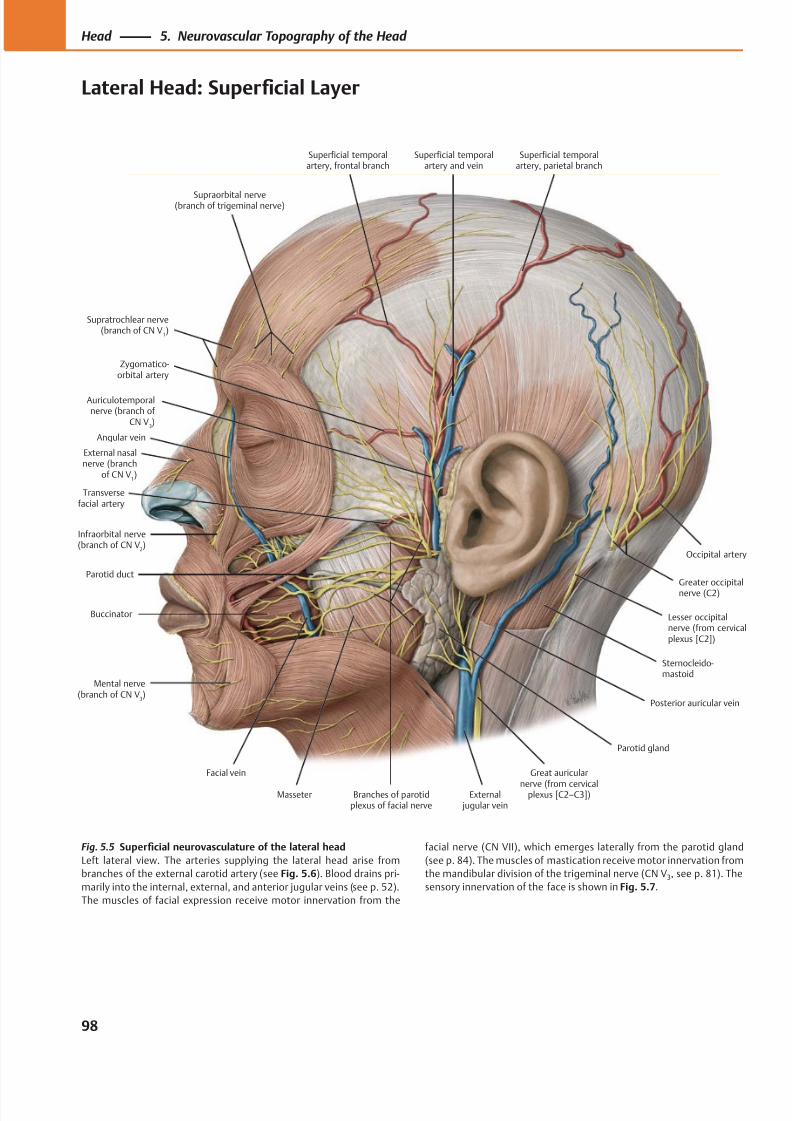
8/15/2019 Head and Neck Anatomy for Dental Medicine - Thieme; (January 26, 2010)
http://slidepdf.com/reader/full/head-and-neck-anatomy-for-dental-medicine-thieme-january-26-2010 111/384
Zygomatico-orbital artery
Supraorbital nerve(branch of trigeminal nerve)
Supratrochlear nerve(branch of CN V
1)
Angular vein
Transversefacial artery
Infraorbital nerve(branch of CN V
2)
Facial vein
Mental nerve(branch of CN V
3)
Parotid duct
Buccinator
Masseter Branches of parotidplexus of facial nerve
External jugular vein
Great auricular
nerve (from cervicalplexus [C2–C3])
Sternocleido-mastoid
Parotid gland
Lesser occipitalnerve (from cervicalplexus [C2])
Posterior auricular vein
Greater occipitalnerve (C2)
Occipital artery
Superficial temporalartery and vein
Auriculotemporalnerve (branch of
CN V3)
Superficial temporalartery, parietal branch
Superficial temporalartery, frontal branch
External nasalnerve (branch
of CN V1)
Fig. 5.5 Superficial neurovasculature of the lateral head
Left lateral view. The arteries supplying the lateral head arise from
branches of the external carotid artery (see Fig. 5.6). Blood drains pri-
marily into the internal, external, and anterior jugular veins (see p. 52).
The muscles of facial expression receive motor innervation from the
facial nerve (CN VII), which emerges laterally from the parotid gland
(see p. 84). The muscles of mastication receive motor innervation from
the mandibular division of the trigeminal nerve (CN V3, see p. 81). The
sensory innervation of the face is shown in Fig. 5.7.
98
Head 5. Neurovascular Topography of the Head
Lateral Head: Superficial Layer
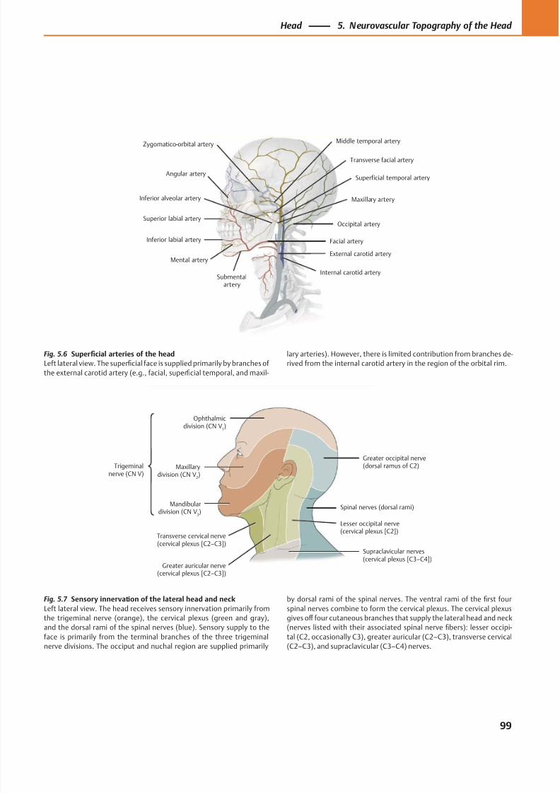
8/15/2019 Head and Neck Anatomy for Dental Medicine - Thieme; (January 26, 2010)
http://slidepdf.com/reader/full/head-and-neck-anatomy-for-dental-medicine-thieme-january-26-2010 112/384
Angular artery
Superior labial artery
Inferior labial artery
Mental artery
Submentalartery
Maxillary artery
Facial artery
Internal carotid artery
External carotid artery
Transverse facial artery
Occipital artery
Middle temporal arteryZygomatico-orbital artery
Inferior alveolar artery
Superficial temporal artery
Mandibulardivision (CN V
3)
Transverse cervical nerve(cervical plexus [C2–C3])
Supraclavicular nerves(cervical plexus [C3–C4])
Spinal nerves (dorsal rami)
Lesser occipital nerve(cervical plexus [C2])
Greater occipital nerve(dorsal ramus of C2)Maxillary
division (CN V2)
Ophthalmicdivision (CN V
1)
Trigeminalnerve (CN V)
Greater auricular nerve(cervical plexus [C2–C3])
Fig. 5.6 Superficial arteries of the head
Left lateral view. The superficial face is supplied primarily by branches of
the external carotid artery (e.g., facial, superficial temporal, and maxil-
lary arteries). However, there is limited contribution from branches de-
rived from the internal carotid artery in the region of the orbital rim.
Fig. 5.7 Sensory innervation of the lateral head and neck
Left lateral view. The head receives sensory innervation primarily from
the trigeminal nerve (orange), the cervical plexus (green and gray),
and the dorsal rami of the spinal nerves (blue). Sensory supply to the
face is primarily from the terminal branches of the three trigeminal
nerve divisions. The occiput and nuchal region are supplied primarily
by dorsal rami of the spinal nerves. The ventral rami of the first four
spinal nerves combine to form the cervical plexus. The cervical plexus
gives off four cutaneous branches that supply the lateral head and neck
(nerves listed with their associated spinal nerve fibers): lesser occipi-
tal (C2, occasionally C3), greater auricular (C2–C3), transverse cervical
(C2–C3), and supraclavicular (C3–C4) nerves.
99
Head 5. Neurovascular Topography of the Head
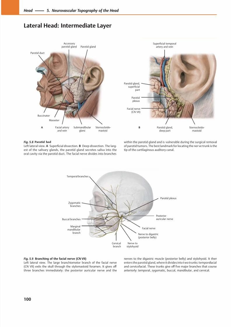
8/15/2019 Head and Neck Anatomy for Dental Medicine - Thieme; (January 26, 2010)
http://slidepdf.com/reader/full/head-and-neck-anatomy-for-dental-medicine-thieme-january-26-2010 113/384
Buccinator
Parotid duct
Masseter
Facial arteryand vein
Submandibulargland
Sternocleido-mastoid
Parotid glandAccessory
parotid gland
A
Parotid gland,superficial
part
Parotidplexus
Parotid gland,deep part
Sternocleido-mastoid
Facial nerve(CN VII)
Superficial temporalartery and vein
B
Temporal branches
Zygomaticbranches
Buccal branches
Marginal
mandibularbranch
Cervicalbranch
Nerve to digastric(posterior belly)
Parotid plexus
Posteriorauricular nerve
Facial nerve
Nerve tostylohyoid
Fig. 5.9 Branching of the facial nerve (CN VII)
Left lateral view. The large branchiomotor branch of the facial nerve
(CN VII) exits the skull through the stylomastoid foramen. It gives off
three branches immediately: the posterior auricular nerve and the
Fig. 5.8 Parotid bed
Left lateral view. A Superficial dissection. B Deep dissection. The larg-
est of the salivary glands, the parotid gland secretes saliva into the
oral cavity via the parotid duct. The facial nerve divides into branches
nerves to the digastric muscle (posterior belly) and stylohyoid. It then
enters the parotid gland, where it divides into two trunks: temporofacial
and cervicofacial. These trunks give off five major branches that course
anteriorly: temporal, zygomatic, buccal, mandibular, and cervical.
within the parotid gland and is vulnerable during the surgical removal
of parotid tumors. The best landmark for locating the ner ve trunk is the
tip of the cartilaginous auditory canal.
100
Head 5. Neurovascular Topography of the Head
Lateral Head: Intermediate Layer
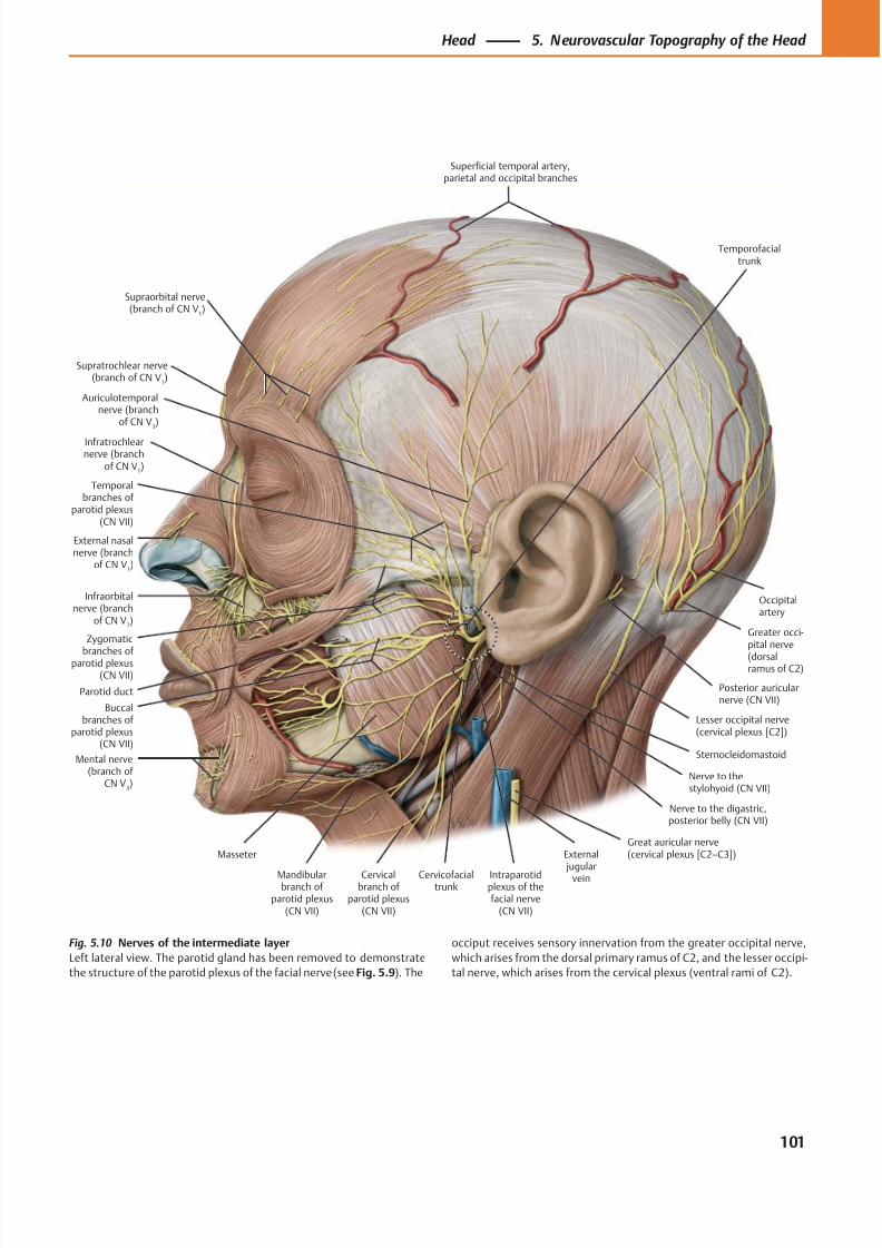
8/15/2019 Head and Neck Anatomy for Dental Medicine - Thieme; (January 26, 2010)
http://slidepdf.com/reader/full/head-and-neck-anatomy-for-dental-medicine-thieme-january-26-2010 114/384
Supratrochlear nerve(branch of CN V
1)
Infratrochlearnerve (branch
of CN V1)
Infraorbitalnerve (branch
of CN V2)
Mental nerve(branch of
CN V3)
Parotid duct
Temporalbranches of
parotid plexus(CN VII)
Zygomatic
branches of parotid plexus(CN VII)
Buccalbranches of
parotid plexus(CN VII)
Mandibularbranch of
parotid plexus(CN VII)
Cervicalbranch of
parotid plexus(CN VII)
Masseter
Intraparotidplexus of thefacial nerve
(CN VII)
Nerve to the digastric,posterior belly (CN VII)
Posterior auricularnerve (CN VII)
Sternocleidomastoid
Lesser occipital nerve(cervical plexus [C2])
Greater occi-pital nerve
(dorsalramus of C2)
Occipitalartery
Auriculotemporalnerve (branch
of CN V3)
Superficial temporal artery,parietal and occipital branches
Cervicofacialtrunk
External jugular
vein
Great auricular nerve(cervical plexus [C2–C3])
Nerve to thestylohyoid (CN VII)
Temporofacialtrunk
Supraorbital nerve(branch of CN V
1)
External nasalnerve (branch
of CN V1)
Fig. 5.10 Nerves of the intermediate layer
Left lateral view. The parotid gland has been removed to demonstrate
the structure of the parotid plexus of the facial nerve (see Fig. 5.9). The
occiput receives sensory innervation from the greater occipital nerve,
which arises from the dorsal primary ramus of C2, and the lesser occipi-
tal nerve, which arises from the cervical plexus (ventral rami of C2).
101
Head 5. Neurovascular Topography of the Head
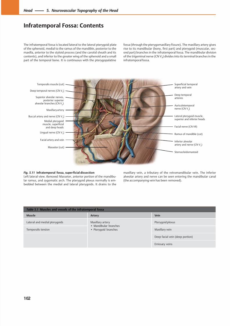
8/15/2019 Head and Neck Anatomy for Dental Medicine - Thieme; (January 26, 2010)
http://slidepdf.com/reader/full/head-and-neck-anatomy-for-dental-medicine-thieme-january-26-2010 115/384
Deep temporal nerves (CN V3)
Temporalis muscle (cut)
Maxillary artery
Superior alveolar nerves,posterior superior
alveolar branches (CN V2)
Medial pterygoidmuscle, superficial
and deep heads
Lingual nerve (CN V3)
Masseter (cut)
Buccal artery and nerve (CN V3)
Facial artery and vein
Superficial temporalartery and vein
Deep temporalarteries
Lateral pterygoid muscle,superior and inferior heads
Inferior alveolarartery and nerve (CN V
3)
Ramus of mandible (cut)
Sternocleidomastoid
Facial nerve (CN VII)
Auriculotemporalnerve (CN V
3)
Table 5.1 Muscles and vessels of the infratemporal fossa
Muscle Artery Vein
Lateral and medial pterygoids Maxillary artery
• Mandibular branches
• Pterygoid branches
Pterygoid plexus
Temporalis tendon Maxillary vein
Deep facial vein (deep portion)
Emissary veins
Fig. 5.11 Infratemporal fossa, superficial dissection
Left lateral view. Removed: Masseter, anterior portion of the mandibu-
lar ramus, and zygomatic arch. The pterygoid plexus normally is em-
bedded between the medial and lateral pterygoids. It drains to the
The infratemporal fossa is located lateral to the lateral pterygoid plate
of the sphenoid, medial to the ramus of the mandible, posterior to the
maxilla, anterior to the styloid process (and the carotid sheath and its
contents), and inferior to the greater wing of the sphenoid and a smallpart of the temporal bone. It is continuous with the pterygopalatine
maxillary vein, a tributary of the retromandibular vein. The inferior
alveolar artery and nerve can be seen entering the mandibular canal
(the accompanying vein has been removed).
fossa (through the pterygomaxillary fissure). The maxillary artery gives
rise to its mandibular (bony, first part) and pterygoid (muscular, sec-
ond part) branches in the infratemporal fossa. The mandibular division
of the trigeminal nerve (CN V3) divides into its terminal branches in theinfratemporal fossa.
102
Head 5. Neurovascular Topography of the Head
Infratemporal Fossa: Contents
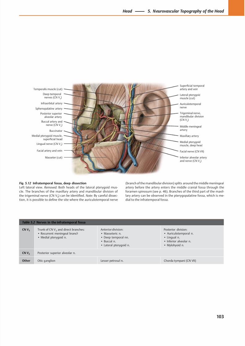
8/15/2019 Head and Neck Anatomy for Dental Medicine - Thieme; (January 26, 2010)
http://slidepdf.com/reader/full/head-and-neck-anatomy-for-dental-medicine-thieme-january-26-2010 116/384
Trigeminal nerve,mandibular division
(CN V3)
Deep temporalnerves (CN V
3)
Lateral pterygoidmuscle (cut)
Temporalis muscle (cut)
Sphenopalatine artery
Infraorbital artery
Posterior superioralveolar artery
Buccinator
Buccal artery andnerve (CN V
3)
Facial artery and vein
Lingual nerve (CN V3)
Medial pterygoidmuscle, deep head
Inferior alveolar arteryand nerve (CN V
3)
Masseter (cut)
Maxillary artery
Facial nerve (CN VII)
Middle meningealartery
Superficial temporalartery and vein
Auriculotemporalnerve
Medial pterygoid muscle,superficial head
Table 5.2 Nerves in the infratemporal fossa
CN V3 Trunk of CN V3 and direct branches:
• Recurrent meningeal branch
• Medial pterygoid n.
Anterior division:
• Masseteric n.
• Deep temporal nn.
• Buccal n.• Lateral pterygoid n.
Posterior division:
• Auriculotemporal n.
• Lingual n.
• Inferior alveolar n.• Mylohyoid n.
CN V2 Posterior superior alveolar n.
Other Otic ganglion Lesser petrosal n. Chorda tympani (CN VII)
Fig. 5.12 Infratemporal fossa, deep dissection
Left lateral view. Removed: Both heads of the lateral pterygoid mus-
cle. The branches of the maxillary artery and mandibular division of
the trigeminal nerve (CN V3) can be identified. Note: By careful dissec-
tion, it is possible to define the site where the auriculotemporal nerve
(branch of the mandibular division) splits around the middle meningeal
artery before the artery enters the middle cranial fossa through the
foramen spinosum (see p. 46). Branches of the third part of the maxil-
lary artery can be observed in the pterygopalatine fossa, which is me-
dial to the infratemporal fossa.
103
Head 5. Neurovascular Topography of the Head
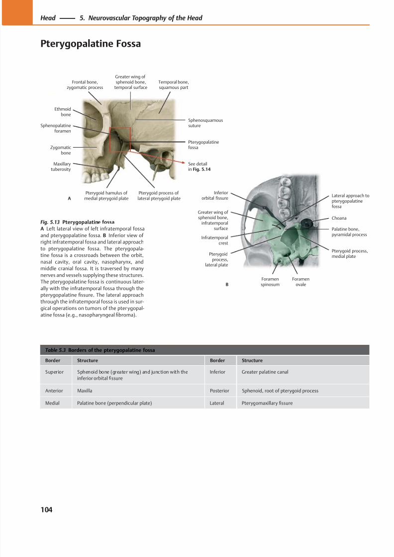
8/15/2019 Head and Neck Anatomy for Dental Medicine - Thieme; (January 26, 2010)
http://slidepdf.com/reader/full/head-and-neck-anatomy-for-dental-medicine-thieme-january-26-2010 117/384
Ethmoidbone
Sphenopalatineforamen
Zygomaticbone
Maxillarytuberosity
Pterygoid hamulus of medial pterygoid plate Pterygoid process oflateral pterygoid plate
Pterygopalatinefossa
Sphenosquamoussuture
Temporal bone,squamous part
Greater wing ofsphenoid bone,
temporal surfaceFrontal bone,
zygomatic process
See detailin Fig. 5.14
A Inferiororbital fissure
Greater wing of sphenoid bone,
infratemporalsurface
Infratemporalcrest
Pterygoidprocess,
lateral plate
Foramenspinosum
Foramenovale
Pterygoid process,medial plate
Palatine bone,pyramidal process
Choana
Lateral approach topterygopalatinefossa
B
Table 5.3 Borders of the pterygopalatine fossa
Border Structure Border Structure
Superior Sphenoid bone (greater wing) and junction with the
inferior orbital fissure
Inferior Greater palatine canal
Anterior Maxilla Posterior Sphenoid, root of pterygoid process
Medial Palatine bone (perpendicular plate) Lateral Pterygomaxillary fissure
Fig. 5.13 Pterygopalatine fossa
A Left lateral view of left infratemporal fossa
and pterygopalatine fossa. B Inferior view of
right infratemporal fossa and lateral approach
to pterygopalatine fossa. The pterygopala-
tine fossa is a crossroads between the orbit,
nasal cavity, oral cavity, nasopharynx, and
middle cranial fossa. It is traversed by many
nerves and vessels supplying these structures.
The pterygopalatine fossa is continuous later-
ally with the infratemporal fossa through the
pterygopalatine fissure. The lateral approach
through the infratemporal fossa is used in sur-
gical operations on tumors of the pterygopal-
atine fossa (e.g., nasopharyngeal fibroma).
104
Head 5. Neurovascular Topography of the Head
Pterygopalatine Fossa
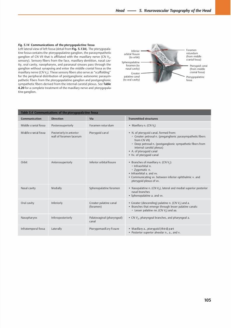
8/15/2019 Head and Neck Anatomy for Dental Medicine - Thieme; (January 26, 2010)
http://slidepdf.com/reader/full/head-and-neck-anatomy-for-dental-medicine-thieme-january-26-2010 118/384
Inferiororbital fissure
(to orbit)
Sphenopalatineforamen (tonasal cavity)
Greaterpalatine canal
(to oral cavity)Pterygopalatinefossa
Pterygoid canal(from middlecranial fossa)
Foramenrotundum
(from middlecranial fossa)
Table 5.4 Communications of the pterygopalatine fossa
Communication Direction Via Transmitted structures
Middle cranial fossa Posterosuperiorly Foramen rotundum • Maxillary n. (CN V2)
Middle cranial fossa Posteriorly in anterior
wall of foramen lacerum
Pterygoid canal • N. of pterygoid canal, formed from:
◦ Greater petrosal n. (preganglionic parasympathetic fibers
from CN VII)
◦ Deep petrosal n. (postganglionic sympathetic fibers from
internal carotid plexus)
• A. of pterygoid canal
• Vv. of pterygoid canal
Orbit Anterosuperiorly Inferior orbital fissure • Branches of maxillary n. (CN V2):
◦ Infraorbital n.
◦ Zygomatic n.
• Infraorbital a. and vv.
• Communicating vv. between inferior ophthalmic v. and
pterygoid plexus of vv.
Nasal cavity Medially Sphenopalatine foramen • Nasopalatine n. (CN V2), lateral and medial superior posterior
nasal branches
• Sphenopalatine a. and vv.
Oral cavity Inferiorly Greater palatine canal
(foramen)
• Greater (descending) palatine n. (CN V2) and a.
• Branches that emerge through lesser palatine canals:
◦ Lesser palatine nn. (CN V2) and aa.
Nasopharynx Inferoposteriorly Palatovaginal (pharyngeal)
canal
• CN V2, pharyngeal branches, and pharyngeal a.
Infratemporal fossa Laterally Pterygomaxillaryfi
ssure • Maxil lary a., pterygoid (third) part• Posterior superior alveolar n., a., and v.
Fig. 5.14 Communications of the pterygopalatine fossa
Left lateral view of left fossa (detail from Fig. 5.13A). The pterygopala-
tine fossa contains the pterygopalatine ganglion, the parasympathetic
ganglion of CN VII that is affi liated with the maxillary nerve (CN V2,sensory). Sensory fibers from the face, maxillary dentition, nasal cav-
ity, oral cavity, nasopharynx, and paranasal sinuses pass through the
ganglion without synapsing and enter the middle cranial fossa as the
maxillary nerve (CN V2). These sensory fibers also serve as “scaff olding”
for the peripheral distribution of postganglionic autonomic parasym-
pathetic fibers from the pterygopalatine ganglion and postganglionic
sympathetic fibers derived from the internal carotid plexus. See Table
4.20 f or a complete treatment of the maxillary nerve and pterygopala-
tine ganglion.
105
Head 5. Neurovascular Topography of the Head
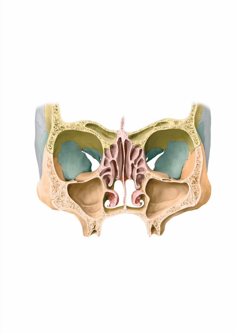
8/15/2019 Head and Neck Anatomy for Dental Medicine - Thieme; (January 26, 2010)
http://slidepdf.com/reader/full/head-and-neck-anatomy-for-dental-medicine-thieme-january-26-2010 119/384
8/15/2019 Head and Neck Anatomy for Dental Medicine - Thieme; (January 26, 2010)
http://slidepdf.com/reader/full/head-and-neck-anatomy-for-dental-medicine-thieme-january-26-2010 120/384
Regions of the Head
6 Orbit & Eye
Bones of the Orbit . . . . . . . . . . . . . . . . . . . . . . . . . . . . . . . . . . 108
Communications of the Orbit . . . . . . . . . . . . . . . . . . . . . . . . . 110
Extraocular Muscles . . . . . . . . . . . . . . . . . . . . . . . . . . . . . . . . . 112
Cranial Nerves of the Extraocular Muscles:
Oculomotor (CN III), Trochlear (CN IV) &
Abducent (CN VI) . . . . . . . . . . . . . . . . . . . . . . . . . . . . . . . . . 114
Neurovasculature of the Orbit . . . . . . . . . . . . . . . . . . . . . . . . 116
Topography of the Orbit (I) . . . . . . . . . . . . . . . . . . . . . . . . . . . 118Topography of the Orbit (II) . . . . . . . . . . . . . . . . . . . . . . . . . . 120
Lacrimal Apparatus . . . . . . . . . . . . . . . . . . . . . . . . . . . . . . . . . 122
Eyeball . . . . . . . . . . . . . . . . . . . . . . . . . . . . . . . . . . . . . . . . . . . 124
Eye: Blood Supply . . . . . . . . . . . . . . . . . . . . . . . . . . . . . . . . . . 126
Eye: Lens & Cornea. . . . . . . . . . . . . . . . . . . . . . . . . . . . . . . . . .128
Eye: Iris & Ocular Chambers . . . . . . . . . . . . . . . . . . . . . . . . . . 130
Eye: Retina . . . . . . . . . . . . . . . . . . . . . . . . . . . . . . . . . . . . . . . . 132
Visual System (I): Overview & Geniculate Part . . . . . . . . . . .134
Visual System (II): Lesions & Nongeniculate Part . . . . . . . . .136
Visual System (III): Reflexes . . . . . . . . . . . . . . . . . . . . . . . . . . . 138
Visual System (IV): Coordination of Eye Movement . . . . . . . 140
7 Nose & Nasal Cavity
Nose: Nasal Skeleton . . . . . . . . . . . . . . . . . . . . . . . . . . . . . . . . 142
Nose: Paranasal Sinuses . . . . . . . . . . . . . . . . . . . . . . . . . . . . . 144
Nasal Cavity . . . . . . . . . . . . . . . . . . . . . . . . . . . . . . . . . . . . . . . 146
Nasal Cavity: Neurovascular Supply . . . . . . . . . . . . . . . . . . . . 148
Nose & Paranasal Sinuses: Histology &
Clinical Anatomy . . . . . . . . . . . . . . . . . . . . . . . . . . . . . . . . . 150
Olfactory System (Smell) . . . . . . . . . . . . . . . . . . . . . . . . . . . . 152
8 Temporal Bone & Ear
Temporal Bone . . . . . . . . . . . . . . . . . . . . . . . . . . . . . . . . . . . . . 154
Ear: Overview & External Ear . . . . . . . . . . . . . . . . . . . . . . . . . .156
External Ear . . . . . . . . . . . . . . . . . . . . . . . . . . . . . . . . . . . . . . . 158
Middle Ear (I): Tympanic Cavity &Pharyngotympanic Tube . . . . . . . . . . . . . . . . . . . . . . . . . . .160
Middle Ear (II): Auditory Ossicles &
Tympanic Cavity . . . . . . . . . . . . . . . . . . . . . . . . . . . . . . . . . . 162
Inner Ear . . . . . . . . . . . . . . . . . . . . . . . . . . . . . . . . . . . . . . . . . .164
Arteries & Veins of the Ear . . . . . . . . . . . . . . . . . . . . . . . . . . . 166
Vestibulocochlear Nerve (CN VIII) . . . . . . . . . . . . . . . . . . . . . 168
Auditory Apparatus . . . . . . . . . . . . . . . . . . . . . . . . . . . . . . . . . 170
Auditory Pathway . . . . . . . . . . . . . . . . . . . . . . . . . . . . . . . . . . 172
Vestibular Apparatus . . . . . . . . . . . . . . . . . . . . . . . . . . . . . . . .174
Vestibular System . . . . . . . . . . . . . . . . . . . . . . . . . . . . . . . . . . 176
9 Oral Cavity & Perioral Regions
Oral Cavity: Overview . . . . . . . . . . . . . . . . . . . . . . . . . . . . . . . 178
Permanent Teeth . . . . . . . . . . . . . . . . . . . . . . . . . . . . . . . . . . . 180
Structure of the Teeth . . . . . . . . . . . . . . . . . . . . . . . . . . . . . . .182
Incisors, Canines & Premolars . . . . . . . . . . . . . . . . . . . . . . . . . 184
Molars . . . . . . . . . . . . . . . . . . . . . . . . . . . . . . . . . . . . . . . . . . . . 186
Deciduous Teeth . . . . . . . . . . . . . . . . . . . . . . . . . . . . . . . . . . . 188
Hard Palate . . . . . . . . . . . . . . . . . . . . . . . . . . . . . . . . . . . . . . . . 190
Mandible & Hyoid Bone . . . . . . . . . . . . . . . . . . . . . . . . . . . . . . 192Temporomandibular Joint (TMJ) . . . . . . . . . . . . . . . . . . . . . . . 194
Temporomandibular Joint (TMJ): Biomechanics . . . . . . . . . .196
Muscles of Mastication: Overview . . . . . . . . . . . . . . . . . . . . . 198
Muscles of Mastication: Deep Muscles . . . . . . . . . . . . . . . . . . 200
Suprahyoid Muscles . . . . . . . . . . . . . . . . . . . . . . . . . . . . . . . . . 202
Lingual Muscles . . . . . . . . . . . . . . . . . . . . . . . . . . . . . . . . . . . . 204
Lingual Mucosa . . . . . . . . . . . . . . . . . . . . . . . . . . . . . . . . . . . . 206
Pharynx & Tonsils . . . . . . . . . . . . . . . . . . . . . . . . . . . . . . . . . . . 208
Pharynx: Divisions & Contents . . . . . . . . . . . . . . . . . . . . . . . . 210
Muscles of the Soft Palate & Pharynx . . . . . . . . . . . . . . . . . . .212
Muscles of the Pharynx . . . . . . . . . . . . . . . . . . . . . . . . . . . . . . 214
Pharynx: Topography & Innervation . . . . . . . . . . . . . . . . . . . .216
Salivary Glands . . . . . . . . . . . . . . . . . . . . . . . . . . . . . . . . . . . . . 218Neurovasculature of the Tongue . . . . . . . . . . . . . . . . . . . . . . 220
Gustatory System . . . . . . . . . . . . . . . . . . . . . . . . . . . . . . . . . . 222
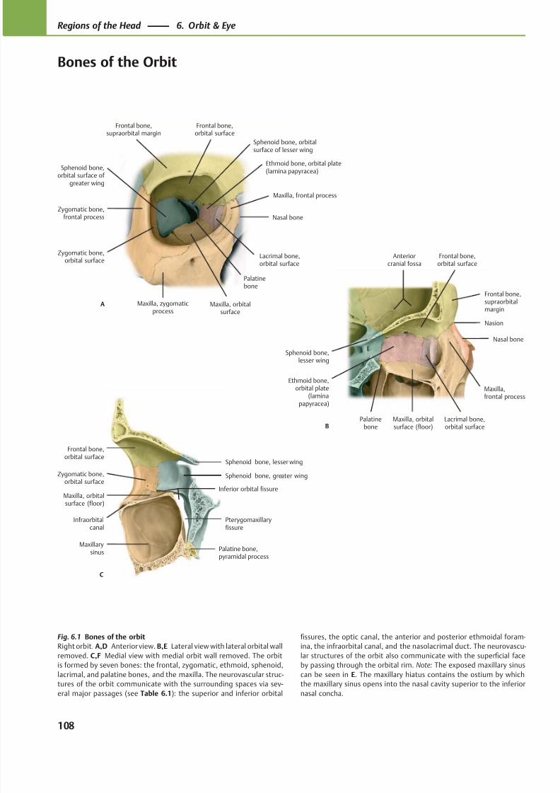
8/15/2019 Head and Neck Anatomy for Dental Medicine - Thieme; (January 26, 2010)
http://slidepdf.com/reader/full/head-and-neck-anatomy-for-dental-medicine-thieme-january-26-2010 121/384
Sphenoid bone,orbital surface of
greater wing
Zygomatic bone,orbital surface
Lacrimal bone,orbital surface
Nasal bone
Maxilla, orbitalsurface
A
Frontal bone,supraorbital margin
Zygomatic bone,frontal process
Frontal bone,orbital surface
Maxilla, zygomaticprocess
Palatinebone
Maxilla, frontal process
Ethmoid bone, orbital plate(lamina papyracea)
Sphenoid bone, orbitalsurface of lesser wing
Nasal bone
Lacrimal bone,orbital surface
Maxilla,frontal process
Palatinebone
Ethmoid bone,orbital plate
(laminapapyracea)
Sphenoid bone,lesser wing
B
Nasion
Maxilla, orbitalsurface (floor)
Frontal bone,supraorbitalmargin
Frontal bone,orbital surface
Anteriorcranial fossa
C
Sphenoid bone, lesser wing
Sphenoid bone, greater wing
Palatine bone,
pyramidal process
Maxilla, orbitalsurface (floor)
Zygomatic bone,orbital surface
Frontal bone,orbital surface
Pterygomaxillaryfissure
Inferior orbital fissure
Infraorbitalcanal
Maxillary
sinus
Fig. 6.1 Bones of the orbit
Right orbit. A,D Anterior view. B,E Lateral view with lateral orbital wall
removed. C,F Medial view with medial orbit wall removed. The orbit
is formed by seven bones: the frontal, zygomatic, ethmoid, sphenoid,
lacrimal, and palatine bones, and the maxilla. The neurovascular struc-
tures of the orbit communicate with the surrounding spaces via sev-
eral major passages (see Table 6.1): the superior and inferior orbital
fissures, the optic canal, the anterior and posterior ethmoidal foram-
ina, the infraorbital canal, and the nasolacrimal duct. The neurovascu-
lar structures of the orbit also communicate with the superficial face
by passing through the orbital rim. Note: The exposed maxillary sinus
can be seen in E. The maxillary hiatus contains the ostium by which
the maxillary sinus opens into the nasal cavity superior to the inferior
nasal concha.
108
Regions of the Head 6. Orbit & Eye
Bones of the Orbit
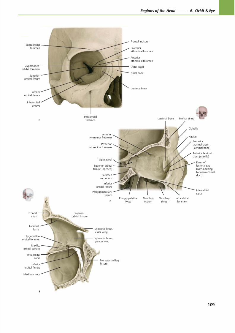
8/15/2019 Head and Neck Anatomy for Dental Medicine - Thieme; (January 26, 2010)
http://slidepdf.com/reader/full/head-and-neck-anatomy-for-dental-medicine-thieme-january-26-2010 122/384
Inferiororbital fissure
Sphenoid bone,
lesser wing
Superiororbital fissure
Sphenoid bone,greater wing
Infraorbitalcanal
Maxilla,orbital surface
Zygomatico-orbital foramen
Maxillary sinus
Frontalsinus
F
Pterygomaxillaryfissure
Lacrimalfossa
Nasion
Anterior lacrimalcrest (maxilla)
Fossa oflacrimal sac(with openingfor nasolacrimal
duct)
Infraorbitalforamen
Infraorbitalcanal
Maxillarysinus
Maxillaryostium
Inferiororbital fissure
Pterygopalatinefossa
Foramenrotundum
Superior orbitalfissure (opened)
Optic canal
Posteriorethmoidal foramen
Anteriorethmoidal foramen
Frontal sinus
E
Lacrimal bone
Posteriorlacrimal crest(lacrimal bone)
Glabella
Pterygomaxillaryfissure
Inferiororbital fissure
Infraorbitalgroove
Superiororbital fissure
Infraorbitalforamen
Lacrimal bone
Nasal bone
Anteriorethmoidal foramen
Posteriorethmoidal foramen
Optic canal
Frontal incisureSupraorbital
foramen
Zygomatico-orbital foramen
D
109
Regions of the Head 6. Orbit & Eye
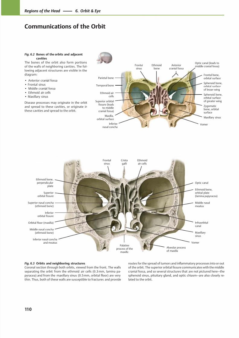
8/15/2019 Head and Neck Anatomy for Dental Medicine - Thieme; (January 26, 2010)
http://slidepdf.com/reader/full/head-and-neck-anatomy-for-dental-medicine-thieme-january-26-2010 123/384
Superior orbitalfissure (leads
to middlecranial fossa)
Ethmoid aircells
Maxillary sinus
Frontalsinus
Anteriorcranial fossa
Parietal bone
Temporal bone
VomerInferiornasal concha
Zygomaticbone, orbitalsurface
Sphenoid bone,orbital surfaceof greater wing
Sphenoid bone,orbital surfaceof lesser wing
Frontal bone,orbital surface
Ethmoidbone
Maxilla,
orbital surface
Optic canal (leads tomiddle cranial fossa)
Ethmoid bone,perpendicular
plate
Superior nasal concha(ethmoid bone)
Middle nasal concha(ethmoid bone)
Inferior nasal conchaand meatus
Palatineprocess of the
maxilla
Superiororbital fissure
Maxillary
sinus
Infraorbitalcanal
Inferiororbital fissure
Middle nasalmeatus
Optic canal
Ethmoid bone,orbital plate(lamina papyracea)
Frontalsinus
Cristagalli
Ethmoidair cells
Vomer
Orbital floor (maxilla)
Alveolar processof maxilla
Fig. 6.2 Bones of the orbits and adjacent
cavitiesThe bones of the orbit also form portions
of the walls of neighboring cavities. The fol-
lowing adjacent structures are visible in the
diagram:
• Anterior cranial fossa
• Frontal sinus
• Middle cranial fossa
• Ethmoid air cells
• Maxillary sinus
Disease processes may originate in the orbit
and spread to these cavities, or originate in
these cavities and spread to the orbit.
Fig. 6.3 Orbits and neighboring structures
Coronal section through both orbits, viewed from the front. The walls
separating the orbit from the ethmoid air cells (0.3 mm, lamina pa-
pyracea) and from the maxillary sinus (0.5 mm, orbital floor) are very
thin. Thus, both of these walls are susceptible to fractures and provide
routes for the spread of tumors and inflammatory processes into or out
of the orbit. The superior orbital fissure communicates with the middle
cranial fossa, and so several structures that are not pictured here—the
sphenoid sinus, pituitary gland, and optic chiasm—are also closely re-
lated to the orbit.
110
Regions of the Head 6. Orbit & Eye
Communications of the Orbit
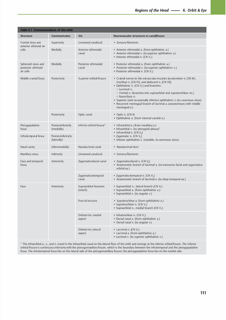
8/15/2019 Head and Neck Anatomy for Dental Medicine - Thieme; (January 26, 2010)
http://slidepdf.com/reader/full/head-and-neck-anatomy-for-dental-medicine-thieme-january-26-2010 124/384
Table 6.1 Communications of the orbit
Structure Communicates Via Neurovascular structures in canal/fissure
Frontal sinus and
anterior ethmoid air
cells
Superiorly Unnamed canaliculi • Sensory filaments
Medially Anterior ethmoidal
canal
• Anterior ethmoidal a. (from ophthalmic a.)
• Anterior ethmoidal v. (to superior ophthalmic v.)
• Anterior ethmoidal n. (CN V1)
Sphenoid sinus and
posterior ethmoid
air cells
Medially Posterior ethmoidal
canal
• Posterior ethmoidal a. (from ophthalmic a.)
• Posterior ethmoidal v. (to superior ophthalmic v.)
• Posterior ethmoidal n. (CN V1)
Middle cranial fossa Posteriorly Superior orbital fissure • Cranial nerves to the extraocular muscles (oculomotor n. [CN III],
trochlear n. [CN IV], and abducent n. [CN VI])
• Ophthalmic n. (CN V1) and branches:
◦ Lacrimal n.
◦ Frontal n. (branches into supraorbital and supratrochlear nn.)
◦ Nasociliary n.
• Superior (and occasionally inferior) ophthalmic v. (to cavernous sinus)
• Recurrent meningeal branch of lacrimal a. (anastomoses with middle
meningeal a.)
Posteriorly Optic canal • Optic n. (CN II)
• Ophthalmic a. (from internal carotid a.)
Pterygopalatine
fossa
Posteroinferiorly
(medially)
Inferior orbital fissure* • Infraorbital a. (from maxillary a.)
• Infraorbital v. (to pterygoid plexus)*
• Infraorbital n. (CN V2)
• Zygomatic n. (CN V2)
• Inferior ophthalmic v. (variable, to cavernous sinus)
Infratemporal fossa Posteroinferiorly
(laterally)
Nasal cavity Inferomedially Nasolacrimal canal • Nasolacrimal duct
Maxillary sinus Inferiorly Unnamed canaliculi • Sensory filaments
Face and temporal
fossa
Anteriorly Zygomaticofacial canal • Zygomaticofacial n. (CN V2)
• Anastomotic branch of lacrimal a. (to transverse facial and zygomatico-
orbital aa.)
Zygomaticotemporal
canal
• Zygomaticotemporal n. (CN V2)
• Anastomotic branch of lacrimal a. (to deep temporal aa.)
Face Anteriorly Supraorbital foramen
(notch)
• Supraorbital n., lateral branch (CN V1)
• Supraorbital a. (from ophthalmic a.)
• Supraorbital v. (to angular v.)
Front al incisure • Supratrochlear a. (from ophthalmic a.)
• Supratrochlear n. (CN V1)
• Supraorbital n., medial branch (CN V1)
Orbital rim, medial
aspect
• Infratrochlear n. (CN V1)
• Dorsal nasal a. (from ophthalmic a.)
• Dorsal nasal v. (to angular v.)
Orbital rim, lateral
aspect
• Lacrimal n. (CN V1)
• Lacrimal a. (from ophthalmic a.)
• Lacrimal v. (to superior ophthalmic v.)
* The infraorbital a., v., and n. travel in the infraorbital canal on the lateral floor of the orbit and emerge at the inferior orbital fissure. The inferior
orbital fissure is continuous inferiorly with the pterygomaxillary fissure, which is the boundary between the infratemporal and the pterygopalatine
fossa. The infratemporal fossa lies on the lateral side of the pterygomaxillary fissure; the pterygopalatine fossa lies on the medial side.
111
Regions of the Head 6. Orbit & Eye
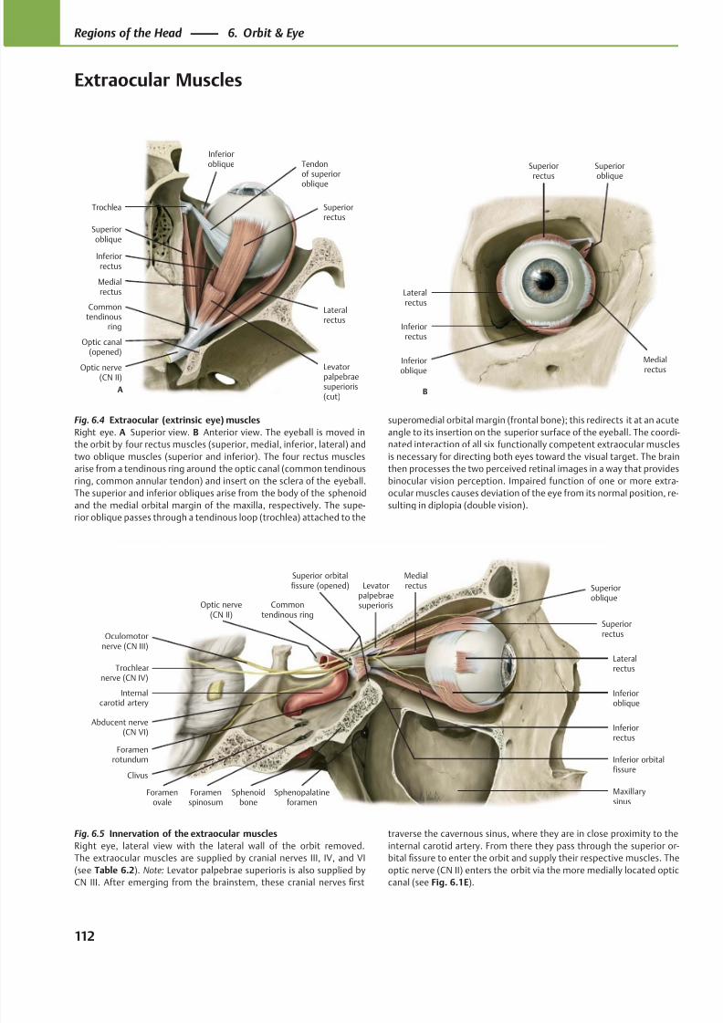
8/15/2019 Head and Neck Anatomy for Dental Medicine - Thieme; (January 26, 2010)
http://slidepdf.com/reader/full/head-and-neck-anatomy-for-dental-medicine-thieme-january-26-2010 125/384
Inferioroblique
Lateralrectus
Inferiorrectus
Commontendinous ring
Trochlearnerve (CN IV)
Sphenoidbone
Clivus
Abducent nerve(CN VI)
Internalcarotid artery
Medialrectus
Superiorrectus
Levatorpalpebraesuperioris
Superioroblique
Foramenrotundum
Oculomotornerve (CN III)
Inferior orbitalfissure
Maxillarysinus
Superior orbitalfissure (opened)
Optic nerve(CN II)
Foramenovale
Foramenspinosum
Sphenopalatineforamen
Optic nerve(CN II)
Commontendinous
ring
Medialrectus
Inferiorrectus
Superiorrectus
Lateralrectus
Superioroblique
Tendonof superioroblique
Trochlea
Inferioroblique
A
Levatorpalpebraesuperioris(cut)
Optic canal(opened)
Lateralrectus
Inferiorrectus
Inferioroblique
Medialrectus
Superior
oblique
Superior
rectus
B
Fig. 6.5 Innervation of the extraocular muscles
Right eye, lateral view with the lateral wall of the orbit removed.
The extraocular muscles are supplied by cranial nerves III, IV, and VI
(see Table 6.2). Note: Levator palpebrae superioris is also supplied by
CN III. After emerging from the brainstem, these cranial nerves first
Fig. 6.4 Extraocular (extrinsic eye) muscles
Right eye. A Superior view. B Anterior view. The eyeball is moved in
the orbit by four rectus muscles (superior, medial, inferior, lateral) and
two oblique muscles (superior and inferior). The four rectus muscles
arise from a tendinous ring around the optic canal (common tendinous
ring, common annular tendon) and insert on the sclera of the eyeball.
The superior and inferior obliques arise from the body of the sphenoid
and the medial orbital margin of the maxilla, respectively. The supe-
rior oblique passes through a tendinous loop (trochlea) attached to the
superomedial orbital margin (frontal bone); this redirects it at an acute
angle to its insertion on the superior surface of the eyeball. The coordi-
nated interaction of all six functionally competent extraocular muscles
is necessary for directing both eyes toward the visual target. The brain
then processes the two perceived retinal images in a way that provides
binocular vision perception. Impaired function of one or more extra-
ocular muscles causes deviation of the eye from its normal position, re-
sulting in diplopia (double vision).
traverse the cavernous sinus, where they are in close proximity to the
internal carotid artery. From there they pass through the superior or-
bital fissure to enter the orbit and supply their respective muscles. The
optic nerve (CN II) enters the orbit via the more medially located optic
canal (see Fig. 6.1E).
112
Regions of the Head 6. Orbit & Eye
Extraocular Muscles
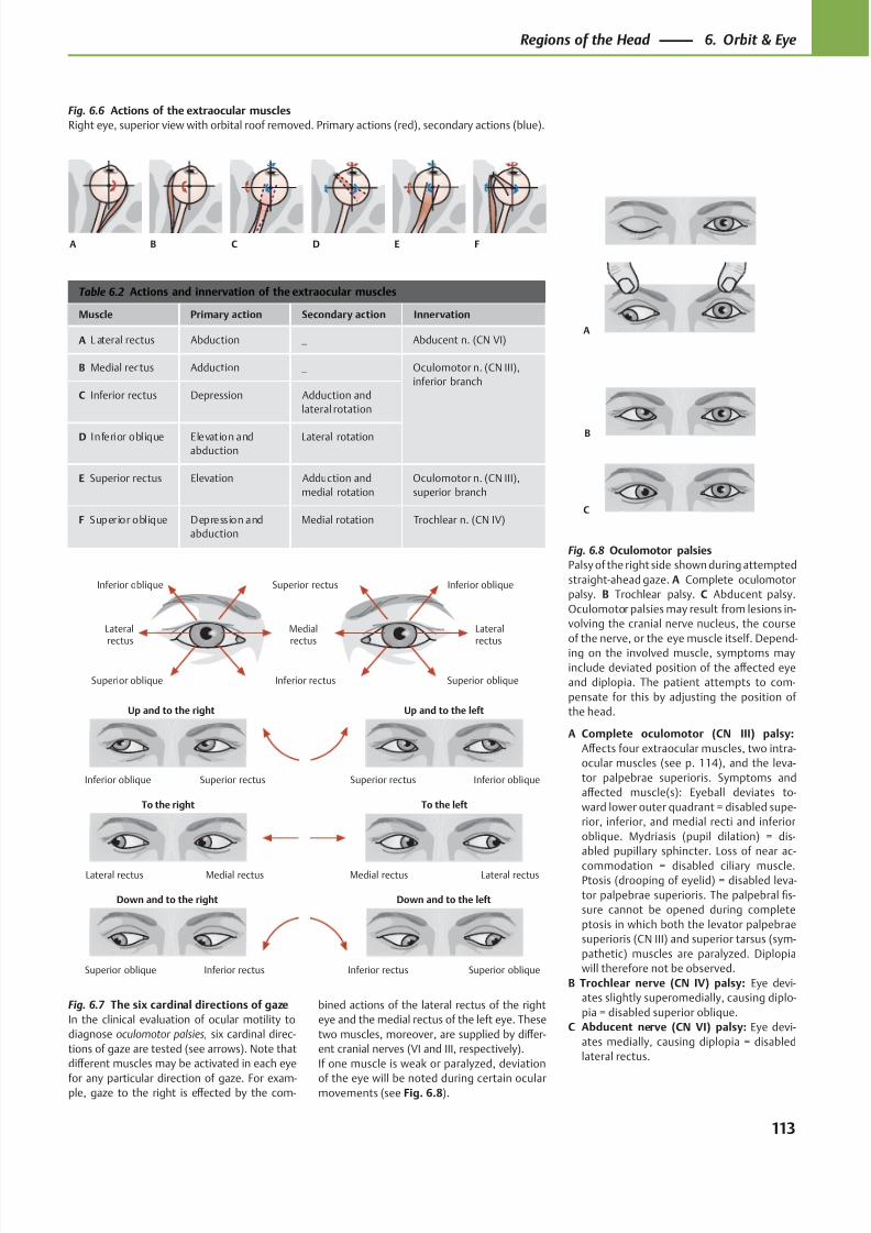
8/15/2019 Head and Neck Anatomy for Dental Medicine - Thieme; (January 26, 2010)
http://slidepdf.com/reader/full/head-and-neck-anatomy-for-dental-medicine-thieme-january-26-2010 126/384
Down and to the left
To the left
Up and to the left
Down and to the right
To the right
Up and to the right
Inferior rectusSuperior oblique
Medial rectusLateral rectus
Superior rectusInferior oblique Superior rectus Inferior oblique
Lateral rectusMedial rectus
Superior obliqueInferior rectus
Inferior oblique Inferior obliqueSuperior rectus
Lateralrectus
Medialrectus
Superior oblique Inferior rectus
Lateralrectus
Superior oblique
A
B
C
A B EC FD
Table 6.2 Actions and innervation of the extraocular muscles
Muscle Primary action Secondary action Innervation
A L ateral rectus Abduction — Abducent n. (CN VI)
B Medial rectus Adduction — Oculomotor n. (CN III),
inferior branch
C Inferior rectus Depression Adduction and
lateral rotation
D Inferior oblique Elevation and
abduction
Lateral rotation
E Superior rectus Elevation Adduction and
medial rotation
Oculomotor n. (CN III),
superior branch
F Superior oblique Depression and
abduction
Medial rotation Trochlear n. (CN IV)
Fig. 6.7 The six cardinal directions of gaze
In the clinical evaluation of ocular motility to
diagnose oculomotor palsies, six cardinal direc-
tions of gaze are tested (see arrows). Note that
diff erent muscles may be activated in each eye
for any particular direction of gaze. For exam-ple, gaze to the right is eff ected by the com-
bined actions of the lateral rectus of the right
eye and the medial rectus of the left eye. These
two muscles, moreover, are supplied by diff er-
ent cranial nerves (VI and III, respectively).
If one muscle is weak or paralyzed, deviation
of the eye will be noted during certain ocularmovements (see Fig. 6.8).
Fig. 6.6 Actions of the extraocular muscles
Right eye, superior view with orbital roof removed. Primary actions (red), secondary actions (blue).
Fig. 6.8 Oculomotor palsies
Palsy of the right side shown during attempted
straight-ahead gaze. A Complete oculomotor
palsy. B Trochlear palsy. C Abducent palsy.
Oculomotor palsies may result from lesions in-
volving the cranial nerve nucleus, the course
of the nerve, or the eye muscle itself. Depend-
ing on the involved muscle, symptoms may
include deviated position of the aff ected eye
and diplopia. The patient attempts to com-
pensate for this by adjusting the position of
the head.
A Complete oculomotor (CN III) palsy:
Aff ects four extraocular muscles, two intra-
ocular muscles (see p. 114), and the leva-
tor palpebrae superioris. Symptoms and
aff ected muscle(s): Eyeball deviates to-
ward lower outer quadrant = disabled supe-
rior, inferior, and medial recti and inferior
oblique. Mydriasis (pupil dilation) = dis-
abled pupillary sphincter. Loss of near ac-
commodation = disabled ciliary muscle.Ptosis (drooping of eyelid) = disabled leva-
tor palpebrae superioris. The palpebral fis-
sure cannot be opened during complete
ptosis in which both the levator palpebrae
superioris (CN III) and superior tarsus (sym-
pathetic) muscles are paralyzed. Diplopia
will therefore not be observed.
B Trochlear nerve (CN IV) palsy: Eye devi-
ates slightly superomedially, causing diplo-
pia = disabled superior oblique.
C Abducent nerve (CN VI) palsy: Eye devi-
ates medially, causing diplopia = disabled
lateral rectus.
113
Regions of the Head 6. Orbit & Eye
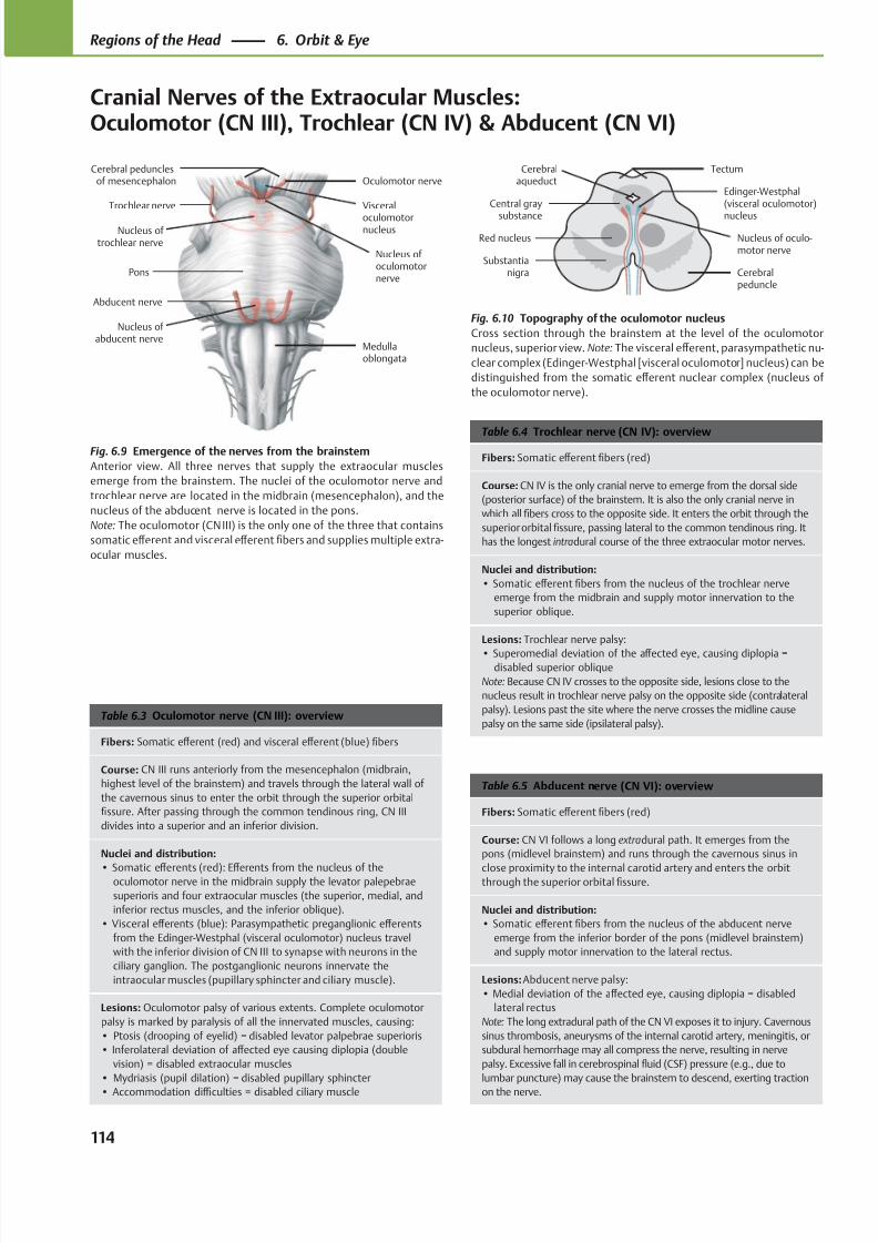
8/15/2019 Head and Neck Anatomy for Dental Medicine - Thieme; (January 26, 2010)
http://slidepdf.com/reader/full/head-and-neck-anatomy-for-dental-medicine-thieme-january-26-2010 127/384
Visceral
oculomotornucleus
Abducent nerve
Trochlear nerve
Oculomotor nerveCerebral peduncles
of mesencephalon
Medullaoblongata
Nucleus of abducent nerve
Nucleus of trochlear nerve
Nucleus of oculomotornerve
Pons
Nucleus of oculo-motor nerve
Edinger-Westphal(visceral oculomotor)
nucleus
Cerebralpeduncle
Cerebralaqueduct
Tectum
Central gray
substance
Red nucleus
Substantianigra
Table 6.5 Abducent nerve (CN VI): overview
Fibers: Somatic eff erent fibers (red)
Course: CN VI follows a long extradural path. It emerges from the
pons (midlevel brainstem) and runs through the cavernous sinus in
close proximity to the internal carotid artery and enters the orbitthrough the superior orbital fissure.
Nuclei and distribution:
• Somatic eff erent fibers from the nucleus of the abducent nerve
emerge from the inferior border of the pons (midlevel brainstem)
and supply motor innervation to the lateral rectus.
Lesions: Abducent nerve palsy:
• Medial deviation of the aff ected eye, causing diplopia = disabled
lateral rectus
Note: The long extradural path of the CN VI exposes it to injury. Cavernous
sinus thrombosis, aneurysms of the internal carotid artery, meningitis, or
subdural hemorrhage may all compress the nerve, resulting in nerve
palsy. Excessive fall in cerebrospinal fluid (CSF) pressure (e.g., due to
lumbar puncture) may cause the brainstem to descend, exerting traction
on the nerve.
Table 6.4 Trochlear nerve (CN IV): overview
Fibers: Somatic eff erent fibers (red)
Course: CN IV is the only cranial nerve to emerge from the dorsal side
(posterior surface) of the brainstem. It is also the only cranial nerve in
which all fibers cross to the opposite side. It enters the orbit through the
superior orbital fissure, passing lateral to the common tendinous ring. It
has the longest intradural course of the three extraocular motor nerves.
Nuclei and distribution:
• Somatic eff erent fibers from the nucleus of the trochlear nerve
emerge from the midbrain and supply motor innervation to the
superior oblique.
Lesions: Trochlear nerve palsy:
• Superomedial deviation of the aff ected eye, causing diplopia =disabled superior oblique
Note: Because CN IV crosses to the opposite side, lesions close to the
nucleus result in trochlear nerve palsy on the opposite side (contralateral
palsy). Lesions past the site where the nerve crosses the midline cause
palsy on the same side (ipsilateral palsy).Table 6.3 Oculomotor nerve (CN III): overview
Fibers: Somatic eff erent (red) and visceral eff erent (blue) fibers
Course: CN III runs anteriorly from the mesencephalon (midbrain,
highest level of the brainstem) and travels through the lateral wall of
the cavernous sinus to enter the orbit through the superior orbital
fissure. After passing through the common tendinous ring, CN III
divides into a superior and an inferior division.
Nuclei and distribution:
• Somatic eff erents (red): Eff erents from the nucleus of theoculomotor nerve in the midbrain supply the levator palepebrae
superioris and four extraocular muscles (the superior, medial, and
inferior rectus muscles, and the inferior oblique).
• Visceral eff erents (blue): Parasympathetic preganglionic eff erents
from the Edinger-Westphal (visceral oculomotor) nucleus travel
with the inferior division of CN III to synapse with neurons in the
ciliary ganglion. The postganglionic neurons innervate the
intraocular muscles (pupillary sphincter and ciliary muscle).
Lesions: Oculomotor palsy of various extents. Complete oculomotor
palsy is marked by paralysis of all the innervated muscles, causing:
• Ptosis (drooping of eyelid) = disabled levator palpebrae superioris
• Inferolateral deviation of aff ected eye causing diplopia (double
vision) = disabled extraocular muscles
• Mydriasis (pupil dilation) = disabled pupillary sphincter
• Accommodation diffi culties = disabled ciliary muscle
Fig. 6.9 Emergence of the nerves from the brainstem
Anterior view. All three nerves that supply the extraocular muscles
emerge from the brainstem. The nuclei of the oculomotor nerve and
trochlear nerve are located in the midbrain (mesencephalon), and the
nucleus of the abducent nerve is located in the pons.
Note: The oculomotor (CN III) is the only one of the three that contains
somatic eff erent and visceral eff erent fibers and supplies multiple extra-
ocular muscles.
Fig. 6.10 Topography of the oculomotor nucleus
Cross section through the brainstem at the level of the oculomotor
nucleus, superior view. Note: The visceral eff erent, parasympathetic nu-
clear complex (Edinger-Westphal [visceral oculomotor] nucleus) can be
distinguished from the somatic eff erent nuclear complex (nucleus of
the oculomotor nerve).
114
Regions of the Head 6. Orbit & Eye
Cranial Nerves of the Extraocular Muscles:Oculomotor (CN III), Trochlear (CN IV) & Abducent (CN VI)
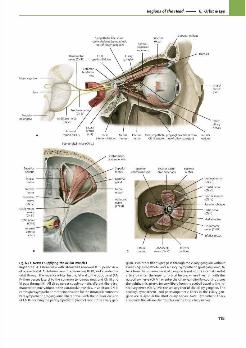
8/15/2019 Head and Neck Anatomy for Dental Medicine - Thieme; (January 26, 2010)
http://slidepdf.com/reader/full/head-and-neck-anatomy-for-dental-medicine-thieme-january-26-2010 128/384
Abducentnerve (CN VI)
Oculomotornerve (CN III)
Trochlear nerve(CN IV)
Frontal nerve(CN V
1)
Lacrimal nerve
(CN V1)
Superiorophthalmic vein
Inferioroblique
Superior oblique
Levator palpe-brae superioris
Superiorrectus
Lateralrectus
Inferior rectus
Medial rectus
Optic nerve(CN II)
C
Supraorbital nerve (CN V1)
Abducentnerve(CN VI)
Trochlearnerve
(CN IV)
Oculomotornerve
(CN III)
Optic nerve(CN II)
Lacrimal
gland
Levator palpe-brae superioris
Superioroblique
Lateralrectus
Inferiorrectus
Medial
rectus
Superiorrectus
B
Internalcarotidartery
Lateralrectus(cut)
Inferioroblique
Medialrectus
Levatorpalpebraesuperioris
Superiorrectus
Superior oblique
Ciliary
ganglion
Abducent nerve
(CN VI)
Trochlear nerve(CN IV)
Oculomotor
nerve (CN III)
Inferiorrectus
Commontendinous
ring
Lateralrectus(cut)A
Shortciliarynerves
Trochlea
CN III,inferior division
Parasympathetic preganglionic fibers fromCN III (motor root of ciliary ganglion)
Medullaoblongata
Pons
Mesencephalon
Sympathetic fibers fromcervical plexus (sympathetic
root of ciliary ganglion)
CN III,
superior division
Internalcarotid plexus
Fig. 6.11 Nerves supplying the ocular muscles
Right orbit. A Lateral view with lateral wall removed. B Superior view
of opened orbit. C Anterior view. Cranial nerves III, IV, and VI enter the
orbit through the superior orbital fissure, lateral to the optic canal (CN
IV then passes lateral to the common tendinous ring, and CN III and
VI pass through it). All three nerves supply somatic eff erent fibers (so-
matomotor innervation) to the extraocular muscles. In addition, CN III
carries parasympathetic motor innervation for the intraocular muscles.
Parasympathetic preganglionic fibers travel with the inferior division
of CN III, forming the parasympathetic (motor) root of the ciliary gan-
glion. Two other fiber types pass through the ciliary ganglion without
synapsing: sympathetic and sensory. Sympathetic (postganglionic) fi-
bers from the superior cervical ganglion travel on the internal carotid
artery to enter the superior orbital fissure, where they run with the
nasociliary nerve (CN V1) or enter the ciliary ganglion by coursing along
the ophthalmic artery. Sensory fibers from the eyeball travel to the na-
sociliary nerve (CN V1) via the sensory root of the ciliary ganglion. The
sensory, sympathetic, and parasympathetic fibers in the ciliary gan-
glion are relayed in the short ciliary nerves. Note: Sympathetic fibers
also reach the intraocular muscles via the long ciliary nerves.
115
Regions of the Head 6. Orbit & Eye
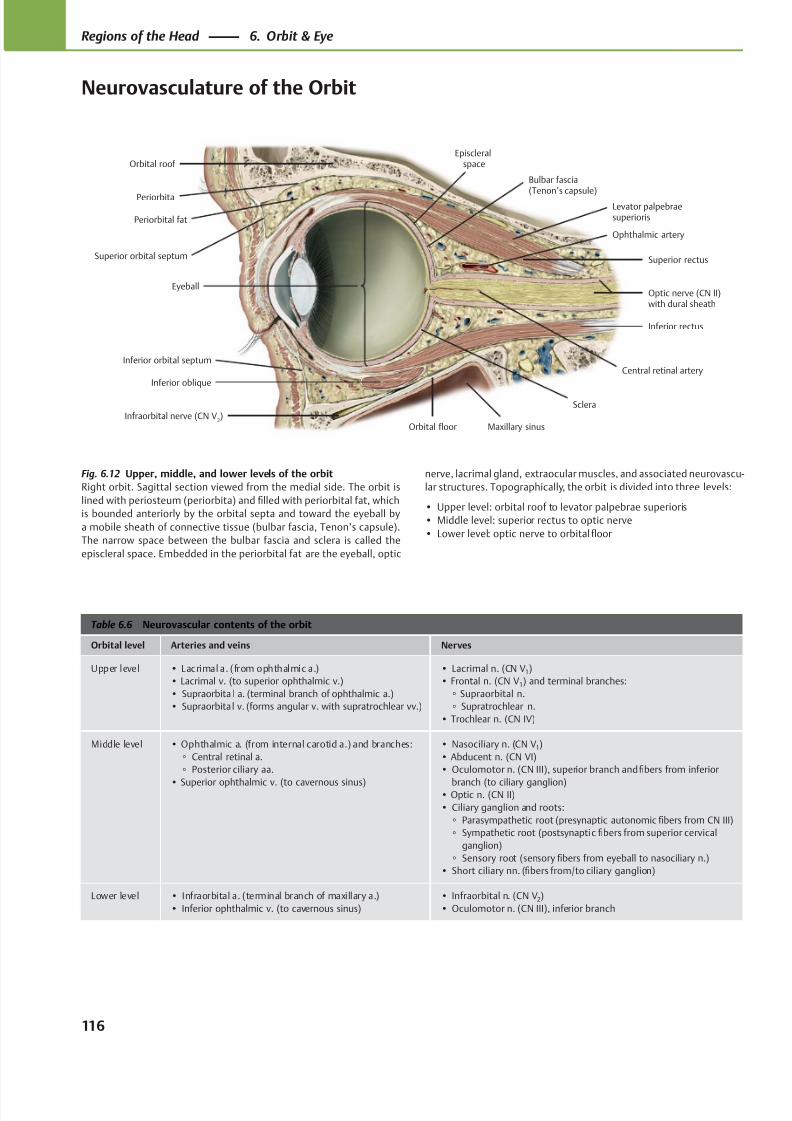
8/15/2019 Head and Neck Anatomy for Dental Medicine - Thieme; (January 26, 2010)
http://slidepdf.com/reader/full/head-and-neck-anatomy-for-dental-medicine-thieme-january-26-2010 129/384
Eyeball
Inferior orbital septum
Infraorbital nerve (CN V2)
Inferior oblique
Maxillary sinusOrbital floor
Inferior rectus
Optic nerve (CN II)with dural sheath
Superior rectus
Bulbar fascia(Tenon’s capsule)
Episcleralspace
Periorbital fat
Levator palpebraesuperioris
Orbital roof
Periorbita
Sclera
Superior orbital septum
Ophthalmic artery
Central retinal artery
Table 6.6 Neurovascular contents of the orbit
Orbital level Arteries and veins Nerves
Upper level • Lacrimal a. (from ophthalmic a.)
• Lacrimal v. (to superior ophthalmic v.)
• Supraorbita l a. (terminal branch of ophthalmic a.)
• Supraorbita l v. (forms angular v. with supratrochlear vv.)
• Lacrimal n. (CN V1)
• Frontal n. (CN V1) and terminal branches:
◦ Supraorbital n.
◦ Supratrochlear n.
• Trochlear n. (CN IV)
Middle level • Ophthalmic a. (from internal carotid a.) and branches:
◦ Central retinal a.
◦ Posterior ciliary aa.
• Superior ophthalmic v. (to cavernous sinus)
• Nasociliary n. (CN V1)
• Abducent n. (CN VI)
• Oculomotor n. (CN III), superior branch and fibers from inferior
branch (to ciliary ganglion)• Optic n. (CN II)
• Ciliary ganglion and roots:
◦ Parasympathetic root (presynaptic autonomic fibers from CN III)
◦ Sympathetic root (postsynaptic fibers from superior cervical
ganglion)
◦ Sensory root (sensory fibers from eyeball to nasociliary n.)
• Short ciliary nn. (fibers from/to ciliary ganglion)
Lower level • Infraorbital a. (terminal branch of maxillary a.)
• Inferior ophthalmic v. (to cavernous sinus)
• Infraorbital n. (CN V2)
• Oculomotor n. (CN III), inferior branch
Fig. 6.12 Upper, middle, and lower levels of the orbit
Right orbit. Sagittal section viewed from the medial side. The orbit is
lined with periosteum (periorbita) and filled with periorbital fat, which
is bounded anteriorly by the orbital septa and toward the eyeball by
a mobile sheath of connective tissue (bulbar fascia, Tenon’s capsule).
The narrow space between the bulbar fascia and sclera is called the
episcleral space. Embedded in the periorbital fat are the eyeball, optic
nerve, lacrimal gland, extraocular muscles, and associated neurovascu-
lar structures. Topographically, the orbit is divided into three levels:
• Upper level: orbital roof to levator palpebrae superioris
• Middle level: superior rectus to optic nerve
• Lower level: optic nerve to orbital floor
116
Regions of the Head 6. Orbit & Eye
Neurovasculature of the Orbit
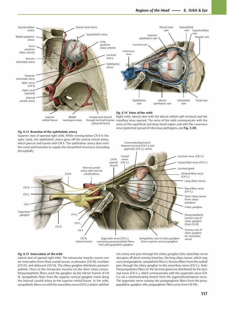
8/15/2019 Head and Neck Anatomy for Dental Medicine - Thieme; (January 26, 2010)
http://slidepdf.com/reader/full/head-and-neck-anatomy-for-dental-medicine-thieme-january-26-2010 130/384
Lacrimal vein
Ophthalmicvein
Facial veinInfraorbitalvein
Inferiorophthalmic vein
Angular vein
Dorsal nasalvein
Supraorbital vein
Superiorophthalmic vein
Cavernoussinus
Supratrochlearvein
LacrimalarteryAnteriorethmoidal artery
Posteriorethmoidal artery
Optic nerve(CN II)
Internalcarotid artery
Middlemeningeal artery
Anastomotic branchthrough lacrimal foramen
(sphenoid bone)
Longposteriorciliary arteries
Shortposterior
ciliary arteries
Supraorbital arteryMedial palpebral
artery
Supratrochlearartery
Dorsal nasal artery
Optic canal(opened)
Superiororbital fissure
Ophthalmicartery
Nasociliary nerve(CN V
1)
CN III,superiorbranch
CN II
CN V1
Internal carotidartery with internalcarotid plexusCN III
CN IV
CN V
CN VI
Trigeminalganglion CN V
3
CN V2
CN III,inferior branch
Sensory root ofciliary ganglion(to nasociliarynerve)Sympathetic root of ciliary ganglion
(from superior cervical ganglion)
Parasympathetic(motor) root of ciliary ganglion
(from CN III)
Ciliary ganglion
Short ciliary nerves(from ciliaryganglion)
Long ciliary nerves
Infratrochlear nerve(CN V
1)
Supraorbital nerve (CN V1)
Lacrimal gland
Lacrimal nerve (CN V1)Frontal
nerve(CN V
1)
Zygomatic nerve (CN V2)
conveying parasympathetic fibersfrom pterygopalatine ganglion
Communicating branchbetween lacrimal (CN V
1) and
zygomatic (CN V2) nerves
Fig. 6.13 Branches of the ophthalmic artery
Superior view of opened right orbit. While running below CN II in the
optic canal, the ophthalmic artery gives off the central retinal artery,
which pierces and travels with CN II. The ophthalmic artery then exits
the canal and branches to supply the intraorbital structures (including
the eyeball).
Fig. 6.14 Veins of the orbitRight orbit, lateral view with the lateral orbital wall removed and the
maxillary sinus opened. The veins of the orbit communicate with the
veins of the superficial and deep facial region and with the cavernous
sinus (potential spread of infectious pathogens, see Fig. 3.20).
Fig. 6.15 Innervation of the orbit
Lateral view of opened right orbit. The extraocular muscles receive mo-
tor innervation from three cranial nerves: oculomotor (CN III), trochlear
(CN IV), and abducent (CN VI). The ciliary ganglion distributes parasym-
pathetic fibers to the intraocular muscles via the short ciliary nerves.
Parasympathetic fibers reach the ganglion via the inferior branch of CN
III. Sympathetic fibers from the superior cervical ganglion travel along
the internal carotid artery to the superior orbital fissure. In the orbit,sympathetic fibers run with the nasociliary nerve (CN V1) and/or ophthal-
mic artery and pass through the ciliary ganglion (the nasociliary nerve
also gives off direct sensory branches, the long ciliary nerves, which may
carry postganglionic sympathetic fibers). Sensory fibers from the eyeball
pass through the ciliary ganglion to the nasociliary nerve (CN V1). Note:
Parasympathetic fibers to the lacrimal gland are distributed by the lacri-
mal nerve (CN V1), which communicates with the zygomatic nerve (CN
V2) via a communicating branch from the zygomaticotemporal nerve.
The zygomatic nerve conveys the postganglionic fibers from the ptery-gopalatine ganglion (the preganglionic fibers arise from CN VII).
117
Regions of the Head 6. Orbit & Eye
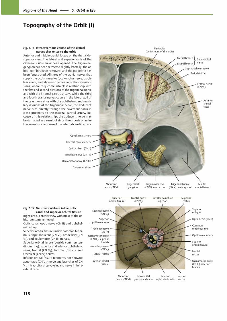
8/15/2019 Head and Neck Anatomy for Dental Medicine - Thieme; (January 26, 2010)
http://slidepdf.com/reader/full/head-and-neck-anatomy-for-dental-medicine-thieme-january-26-2010 131/384
Superiorophthalmic vein
Oculomotor nerve(CN III), superior
branch
Lateral rectus
Nasociliary nerve(CN V
1)
Inferior orbitalfissure
Abducentnerve (CN VI)
Inferiorophthalmic vein
Oculomotor nerve(CN III), inferiorbranch
Superiororbital fissure
Ophthalmic artery
Commontendinous ring
Superioroblique
Optic nerve (CN II)
Levator palpebraesuperioris
Trochlear nerve(CN IV)
Frontal nerve(CN V
1)
Lacrimal nerve(CN V
1)
Superiorrectus
Inferiorrectus
Medialrectus
Superiororbital fissure
Infraorbitalgroove and canal
Ophthalmic artery
Internal carotid artery
Oculomotor nerve (CN III)
Abducentnerve (CN VI)
Trochlear nerve (CN IV)
Periorbita(periosteum of the orbit)
Periorbital fat
SupraorbitalnerveLateral branch
Medial branch
Trigeminal nerve(CN V), sensory root
Trigeminal nerve(CN V), motor root
Trigeminalganglion
Cavernous sinus
Optic chiasm (CN II)
Frontal nerve(CN V
1)
Middlecranial fossa
Anteriorcranialfossa
Supratrochlear nerve
Fig. 6.17 Neurovasculature in the optic
canal and superior orbital fissure
Right orbit, anterior view with most of the or-
bital contents removed.
Optic canal: optic nerve (CN II) and ophthal-mic artery.
Superior orbital fissure (inside common tendi-
nous ring): abducent (CN VI), nasociliary (CN
V1), and oculomotor (CN III) nerves.
Superior orbital fissure (outside common ten-
dinous ring): superior and inferior ophthalmic
veins, frontal (CN V1), lacrimal (CN V1), and
trochlear (CN IV) nerves.
Inferior orbital fissure (contents not shown):
zygomatic (CN V2) nerve and branches of CN
V2, infraorbital artery, vein, and nerve in infra-
orbital canal.
Fig. 6.16 Intracavernous course of the cranial
nerves that enter to the orbit
Anterior and middle cranial fossae on the right side,superior view. The lateral and superior walls of the
cavernous sinus have been opened. The trigeminal
ganglion has been retracted slightly laterally, the or-
bital roof has been removed, and the periorbita has
been fenestrated. All three of the cranial nerves that
supply the ocular muscles (oculomotor nerve, troch-
lear nerve, and abducent nerve) enter the cavernous
sinus, where they come into close relationship with
the first and second divisions of the trigeminal nerve
and with the internal carotid artery. While the third
and fourth cranial nerves course in the lateral wall of
the cavernous sinus with the ophthalmic and maxil-
lary divisions of the trigeminal nerve, the abducent
nerve runs directly through the cavernous sinus in
close proximity to the internal carotid artery. Be-cause of this relationship, the abducent nerve may
be damaged as a result of sinus thrombosis or an in-
tracavernous aneurysm of the internal carotid artery.
118
Regions of the Head 6. Orbit & Eye
Topography of the Orbit (I)
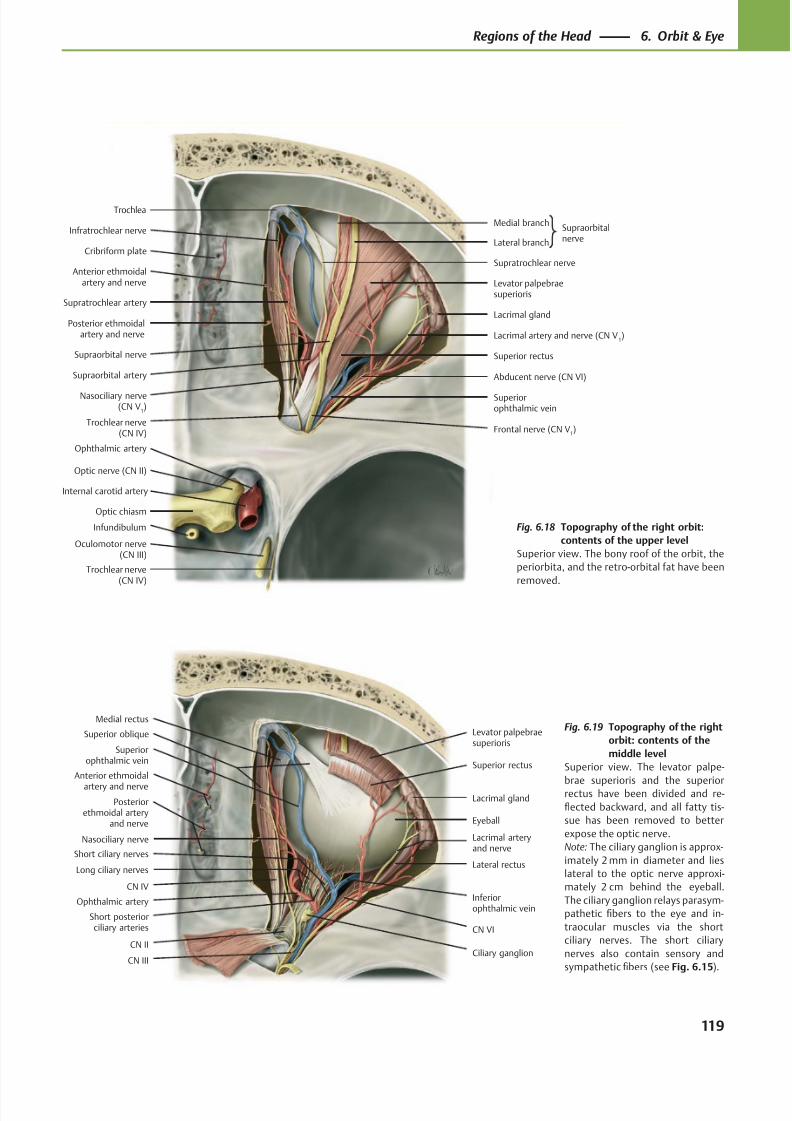
8/15/2019 Head and Neck Anatomy for Dental Medicine - Thieme; (January 26, 2010)
http://slidepdf.com/reader/full/head-and-neck-anatomy-for-dental-medicine-thieme-january-26-2010 132/384
Oculomotor nerve(CN III)
Trochlear nerve(CN IV)
Abducent nerve (CN VI)
Levator palpebraesuperioris
Supraorbital nerve
Lacrimal gland
Lacrimal artery and nerve (CN V1)
Superiorophthalmic vein
Cribriform plate
Supratrochlear artery
Supraorbital artery
Trochlear nerve(CN IV)
Trochlea
Superior rectus
Optic chiasm
Optic nerve (CN II)
Ophthalmic artery
Internal carotid artery
Infratrochlear nerve
Nasociliary nerve(CN V
1)
Posterior ethmoidalartery and nerve
Anterior ethmoidalartery and nerve
SupraorbitalnerveLateral branch
Medial branch
Supratrochlear nerve
Infundibulum
Frontal nerve (CN V1)
Levator palpebraesuperioris
Superior rectus
Lacrimal gland
Ciliary ganglion
Superior oblique
Lacrimal arteryand nerve
CN II
Superiorophthalmic vein
Nasociliary nerve
Medial rectus
Inferiorophthalmic vein
Short ciliary nervesLateral rectus
Short posteriorciliary arteries
CN III
CN VI
Eyeball
CN IV
Anterior ethmoidal
artery and nerve
Posteriorethmoidal artery
and nerve
Long ciliary nerves
Ophthalmic artery
Fig. 6.19 Topography of the right
orbit: contents of the
middle level
Superior view. The levator palpe-
brae superioris and the superiorrectus have been divided and re-
flected backward, and all fatty tis-
sue has been removed to better
expose the optic nerve.
Note: The ciliary ganglion is approx-
imately 2 mm in diameter and lies
lateral to the optic nerve approxi-
mately 2 cm behind the eyeball.
The ciliary ganglion relays parasym-
pathetic fibers to the eye and in-
traocular muscles via the short
ciliary nerves. The short ciliary
nerves also contain sensory and
sympathetic fibers (see Fig. 6.15).
Fig. 6.18 Topography of the right orbit:
contents of the upper level
Superior view. The bony roof of the orbit, the
periorbita, and the retro-orbital fat have been
removed.
119
Regions of the Head 6. Orbit & Eye
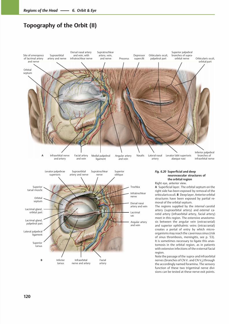
8/15/2019 Head and Neck Anatomy for Dental Medicine - Thieme; (January 26, 2010)
http://slidepdf.com/reader/full/head-and-neck-anatomy-for-dental-medicine-thieme-january-26-2010 133/384
Procerus
Dorsal nasal artery
and vein, withinfratrochlear nerveSupraorbitalartery and nerve
Orbitalseptum
Infraorbital nerveand artery
Facial arteryand vein
Angular arteryand vein
Medial palpebralligament
Nasalis Levator labii superiorisalaeque nasi
Orbicularis oculi,orbital part
Orbicularis oculi,palpebral partDepressorsupercilii
A
Site of emergenceof lacrimal arteryand nerve
Supratrochlear
artery, vein, and nerve
Superior palpebral
branches of supra-orbital nerve
Lateral nasalartery
Inferior palpebralbranches of
infraorbital nerve
Superiortarsal muscle
Orbitalseptum
Lacrimal gland,palpebral part
Lacrimal gland,orbital part
Lateral palpebralligament
Inferiortarsus
Infraorbitalnerve and artery
Dorsal nasalartery and vein
Lacrimalsac
Angular arteryand vein
Superiortarsus
Infratrochlearnerve
Trochlea
Levator palpebraesuperioris
Superioroblique
Supratrochlearnerve
Supraorbitalartery and nerve
B Facialartery
Fig. 6.20 Superficial and deep
neurovascular structures of
the orbital region
Right eye, anterior view.
A Superficial layer. The orbital septum on the
right side has been exposed by removal of the
orbicularis oculi. B Deep layer. Anterior orbital
structures have been exposed by partial re-
moval of the orbital septum.
The regions supplied by the internal carotid
artery (supraorbital artery) and external ca-
rotid artery (infraorbital artery, facial artery)
meet in this region. The extensive anastomo-
sis between the angular vein (extracranial)
and superior ophthalmic veins (intracranial)creates a portal of entry by which micro-
organisms may reach the cavernous sinus (risk
of sinus thrombosis, meningitis, see p. 53).
It is sometimes necessary to ligate this anas-
tomosis in the orbital region, as in patients
with extensive infections of the external facial
region.
Note the passage of the supra- and infraorbital
nerves (branches of CN V1 and CN V2) through
the accordingly named foramina. The sensory
function of these two trigeminal nerve divi-
sions can be tested at these nerve exit points.
120
Regions of the Head 6. Orbit & Eye
Topography of the Orbit (II)
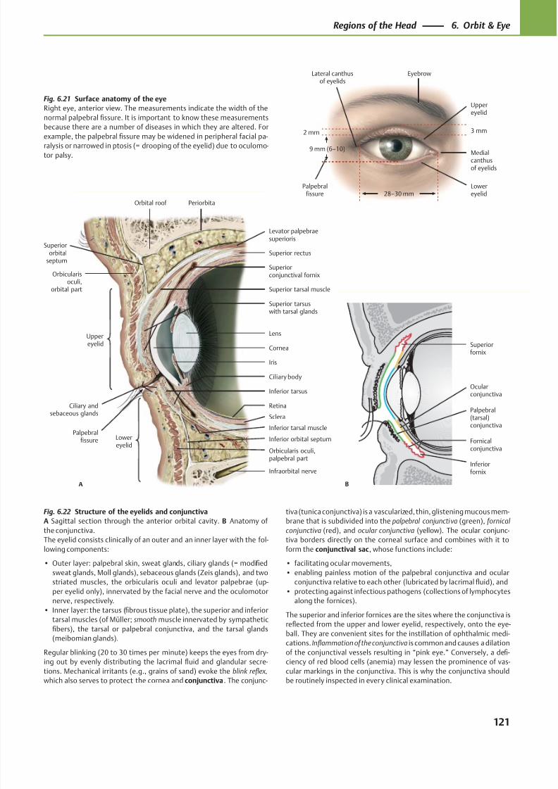
8/15/2019 Head and Neck Anatomy for Dental Medicine - Thieme; (January 26, 2010)
http://slidepdf.com/reader/full/head-and-neck-anatomy-for-dental-medicine-thieme-january-26-2010 134/384
Palpebralfissure
Lateral canthusof eyelids
Lowereyelid
Medialcanthusof eyelids
Uppereyelid
Eyebrow
2 mm
9 mm (6–10)
28–30 mm
3 mm
Iris
Orbital roof
Superiororbital
septum
Orbicularisoculi,orbital part
Uppereyelid
Superior tarsuswith tarsal glands
Ciliary and
sebaceous glands
Inferior tarsus
Lowereyelid
Orbicularis oculi,palpebral part
Inferior tarsal muscle
Infraorbital nerve
Sclera
Retina
Ciliary body
Lens
Cornea
Superior tarsal muscle
Superior rectus
Superior
conjunctival fornix
Levator palpebraesuperioris
Periorbita
A
Palpebralfissure Inferior orbital septum
Palpebral(tarsal)conjunctiva
Inferiorfornix
Fornicalconjunctiva
Ocularconjunctiva
B
Superiorfornix
Fig. 6.21 Surface anatomy of the eye
Right eye, anterior view. The measurements indicate the width of the
normal palpebral fissure. It is important to know these measurements
because there are a number of diseases in which they are altered. For
example, the palpebral fissure may be widened in peripheral facial pa-ralysis or narrowed in ptosis (= drooping of the eyelid) due to oculomo-
tor palsy.
Fig. 6.22 Structure of the eyelids and conjunctiva
A Sagittal section through the anterior orbital cavity. B Anatomy of
the conjunctiva.
The eyelid consists clinically of an outer and an inner layer with the fol-
lowing components:• Outer layer: palpebral skin, sweat glands, ciliary glands (= modified
sweat glands, Moll glands), sebaceous glands (Zeis glands), and two
striated muscles, the orbicularis oculi and levator palpebrae (up-
per eyelid only), innervated by the facial nerve and the oculomotor
nerve, respectively.
• Inner layer: the tarsus (fibrous tissue plate), the superior and inferior
tarsal muscles (of Müller; smooth muscle innervated by sympathetic
fibers), the tarsal or palpebral conjunctiva, and the tarsal glands
(meibomian glands).
Regular blinking (20 to 30 times per minute) keeps the eyes from dry-
ing out by evenly distributing the lacrimal fluid and glandular secre-
tions. Mechanical irritants (e.g., grains of sand) evoke the blink reflex,
which also serves to protect the cornea and conjunctiva. The conjunc-
tiva (tunica conjunctiva) is a vascularized, thin, glistening mucous mem-
brane that is subdivided into the palpebral conjunctiva (green), fornical
conjunctiva (red), and ocular conjunctiva (yellow). The ocular conjunc-
tiva borders directly on the corneal surface and combines with it to
form the conjunctival sac, whose functions include:• facilitating ocular movements,
• enabling painless motion of the palpebral conjunctiva and ocular
conjunctiva relative to each other (lubricated by lacrimal fluid), and
• protecting against infectious pathogens (collections of lymphocytes
along the fornices).
The superior and inferior fornices are the sites where the conjunctiva is
reflected from the upper and lower eyelid, respectively, onto the eye-
ball. They are convenient sites for the instillation of ophthalmic medi-
cations. Inflammation of the conjunctiva is common and causes a dilation
of the conjunctival vessels resulting in “pink eye.” Conversely, a defi-
ciency of red blood cells (anemia) may lessen the prominence of vas-
cular markings in the conjunctiva. This is why the conjunctiva should
be routinely inspected in every clinical examination.
121
Regions of the Head 6. Orbit & Eye
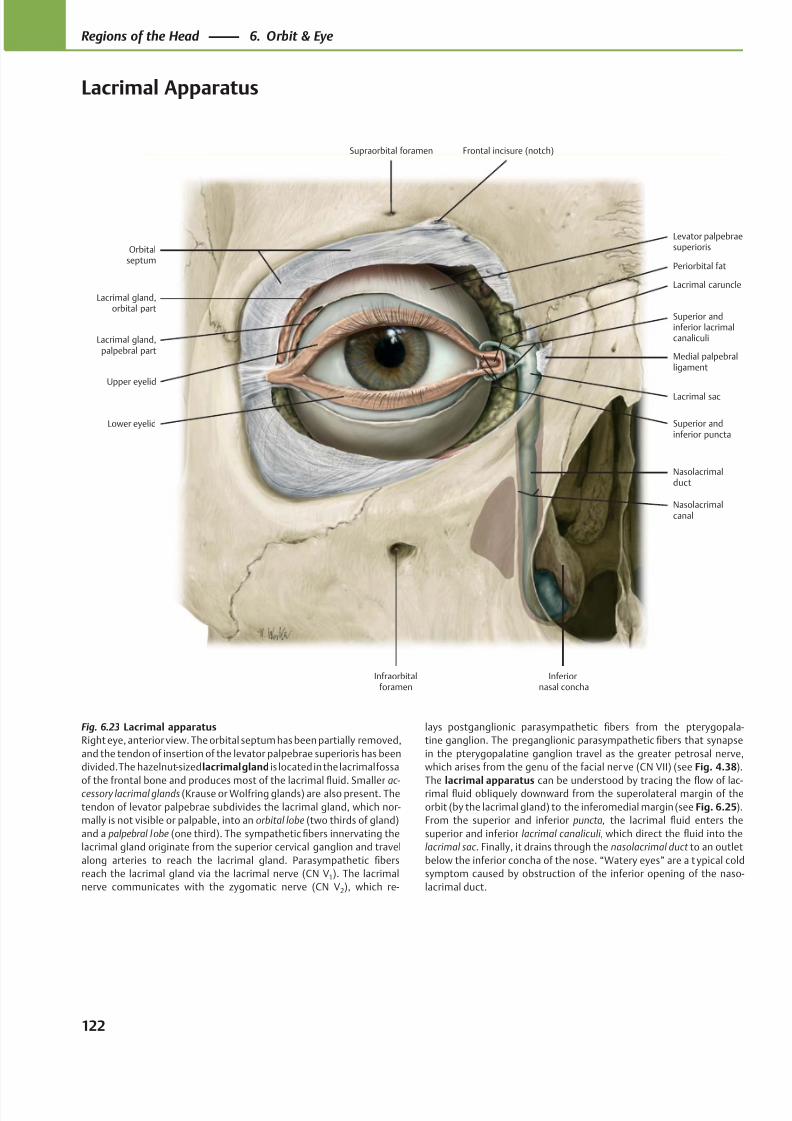
8/15/2019 Head and Neck Anatomy for Dental Medicine - Thieme; (January 26, 2010)
http://slidepdf.com/reader/full/head-and-neck-anatomy-for-dental-medicine-thieme-january-26-2010 135/384
Levator palpebraesuperiorisOrbital
septum
Lacrimal gland,orbital part
Lacrimal gland,palpebral part
Lower eyelid
Upper eyelid
Infraorbitalforamen
Superior andinferior puncta
Inferiornasal concha
Nasolacrimalduct
Lacrimal sac
Medial palpebralligament
Superior andinferior lacrimalcanaliculi
Lacrimal caruncle
Periorbital fat
Frontal incisure (notch)Supraorbital foramen
Nasolacrimalcanal
Fig. 6.23 Lacrimal apparatus
Right eye, anterior view. The orbital septum has been partially removed,
and the tendon of insertion of the levator palpebrae superioris has been
divided. The hazelnut-sized lacrimal gland is located in the lacrimal fossa
of the frontal bone and produces most of the lacrimalfl
uid. Smaller ac- cessory lacrimal glands (Krause or Wolfring glands) are also present. The
tendon of levator palpebrae subdivides the lacrimal gland, which nor-
mally is not visible or palpable, into an orbital lobe (two thirds of gland)
and a palpebral lobe (one third). The sympathetic fibers innervating the
lacrimal gland originate from the superior cervical ganglion and travel
along arteries to reach the lacrimal gland. Parasympathetic fibers
reach the lacrimal gland via the lacrimal nerve (CN V1). The lacrimal
nerve communicates with the zygomatic nerve (CN V2), which re-
lays postganglionic parasympathetic fibers from the pterygopala-
tine ganglion. The preganglionic parasympathetic fibers that synapse
in the pterygopalatine ganglion travel as the greater petrosal nerve,
which arises from the genu of the facial nerve (CN VII) (see Fig. 4.38).
The lacrimal apparatus can be understood by tracing thefl
ow of lac-rimal fluid obliquely downward from the superolateral margin of the
orbit (by the lacrimal gland) to the inferomedial margin (see Fig. 6.25).
From the superior and inferior puncta, the lacrimal fluid enters the
superior and inferior lacrimal canaliculi, which direct the fluid into the
lacrimal sac . Finally, it drains through the nasolacrimal duct to an outlet
below the inferior concha of the nose. “Watery eyes” are a t ypical cold
symptom caused by obstruction of the inferior opening of the naso-
lacrimal duct.
122
Regions of the Head 6. Orbit & Eye
Lacrimal Apparatus
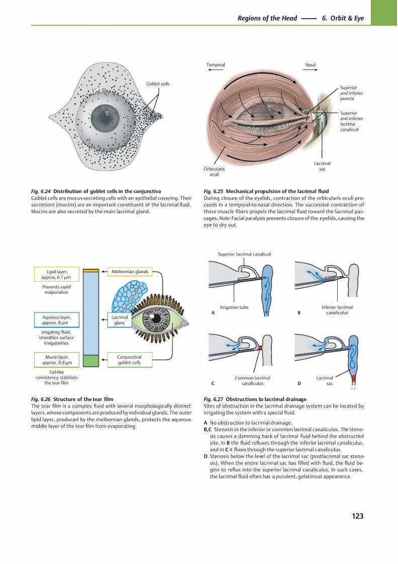
8/15/2019 Head and Neck Anatomy for Dental Medicine - Thieme; (January 26, 2010)
http://slidepdf.com/reader/full/head-and-neck-anatomy-for-dental-medicine-thieme-january-26-2010 136/384
Goblet cells
Prevents rapidevaporation
Irrigating fluid,smoothes surface
irregularities
Gel-likeconsistency stabilizes
the tear film
Aqueous layer,approx. 8 μm
Lipid layer,approx. 0.1 μm
Mucin layer,approx. 0.8 μm
Meibomian glands
Lacrimalgland
Conjunctivalgoblet cells
Orbicularisoculi
Lacrimalsac
NasalTemporal
Superiorand inferior
puncta
Superiorand inferiorlacrimalcanaliculi
Common lacrimalcanaliculusC D
Lacrimalsac
Irrigation tubeA
Inferior lacrimalcanaliculusB
Superior lacrimal canaliculi
Fig. 6.26 Structure of the tear film
The tear film is a complex fluid with several morphologically distinct
layers, whose components are produced by individual glands. The outer
lipid layer, produced by the meibomian glands, protects the aqueous
middle layer of the tear film from evaporating.
Fig. 6.24 Distribution of goblet cells in the conjunctiva
Goblet cells are mucus-secreting cells with an epithelial covering. Theirsecretions (mucins) are an important constituent of the lacrimal fluid.
Mucins are also secreted by the main lacrimal gland.
Fig. 6.25 Mechanical propulsion of the lacrimal fluid
During closure of the eyelids, contraction of the orbicularis oculi pro-ceeds in a temporal-to-nasal direction. The successive contraction of
these muscle fibers propels the lacrimal fluid toward the lacrimal pas-
sages. Note: Facial paralysis prevents closure of the eyelids, causing the
eye to dry out.
Fig. 6.27 Obstructions to lacrimal drainage
Sites of obstruction in the lacrimal drainage system can be located by
irrigating the system with a special fluid.
A No obstruction to lacrimal drainage.
B,C Stenosis in the inferior or common lacrimal canaliculus. The steno-
sis causes a damming back of lacrimal fluid behind the obstructed
site. In B the fluid refluxes through the inferior lacrimal canaliculus,
and in C it flows through the superior lacrimal canaliculus.
D Stenosis below the level of the lacrimal sac (postlacrimal sac steno-
sis). When the entire lacrimal sac has filled with fluid, the fluid be-
gins to reflux into the superior lacrimal canaliculus. In such cases,
the lacrimal fluid often has a purulent, gelatinous appearance.
123
Regions of the Head 6. Orbit & Eye
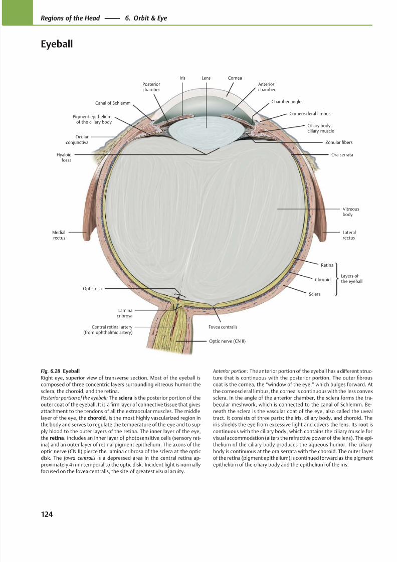
8/15/2019 Head and Neck Anatomy for Dental Medicine - Thieme; (January 26, 2010)
http://slidepdf.com/reader/full/head-and-neck-anatomy-for-dental-medicine-thieme-january-26-2010 137/384
LensIris
Canal of Schlemm
Pigment epitheliumof the ciliary body
Posteriorchamber
Medialrectus
Optic disk
Laminacribrosa
Central retinal artery(from ophthalmic artery)
Optic nerve (CN II)
Fovea centralis
Lateralrectus
Vitreousbody
Ora serrata
Zonular fibers
Ciliary body,ciliary muscle
Corneoscleral limbus
Chamber angle
Cornea
Anteriorchamber
Sclera
Choroid
Retina
Ocularconjunctiva
Hyaloidfossa
Layers of the eyeball
Fig. 6.28 Eyeball
Right eye, superior view of transverse section. Most of the eyeball is
composed of three concentric layers surrounding vitreous humor: the
sclera, the choroid, and the retina.Posterior portion of the eyeball: The sclera is the posterior portion of the
outer coat of the eyeball. It is a firm layer of connective tissue that gives
attachment to the tendons of all the extraocular muscles. The middle
layer of the eye, the choroid, is the most highly vascularized region in
the body and serves to regulate the temperature of the eye and to sup-
ply blood to the outer layers of the retina. The inner layer of the eye,
the retina, includes an inner layer of photosensitive cells (sensory ret-
ina) and an outer layer of retinal pigment epithelium. The axons of the
optic nerve (CN II) pierce the lamina cribrosa of the sclera at the optic
disk. The fovea centralis is a depressed area in the central retina ap-
proximately 4 mm temporal to the optic disk. Incident light is normally
focused on the fovea centralis, the site of greatest visual acuity.
Anterior portion: The anterior portion of the eyeball has a diff erent struc-
ture that is continuous with the posterior portion. The outer fibrous
coat is the cornea, the “window of the eye,” which bulges forward. At
the corneoscleral limbus, the cornea is continuous with the less convexsclera. In the angle of the anterior chamber, the sclera forms the tra-
becular meshwork, which is connected to the canal of Schlemm. Be-
neath the sclera is the vascular coat of the eye, also called the uveal
tract. It consists of three parts: the iris, ciliary body, and choroid. The
iris shields the eye from excessive light and covers the lens. Its root is
continuous with the ciliary body, which contains the ciliary muscle for
visual accommodation (alters the refractive power of the lens). The epi-
thelium of the ciliary body produces the aqueous humor. The ciliary
body is continuous at the ora serrata with the choroid. The outer layer
of the retina (pigment epithelium) is continued forward as the pigment
epithelium of the ciliary body and the epithelium of the iris.
124
Regions of the Head 6. Orbit & Eye
Eyeball
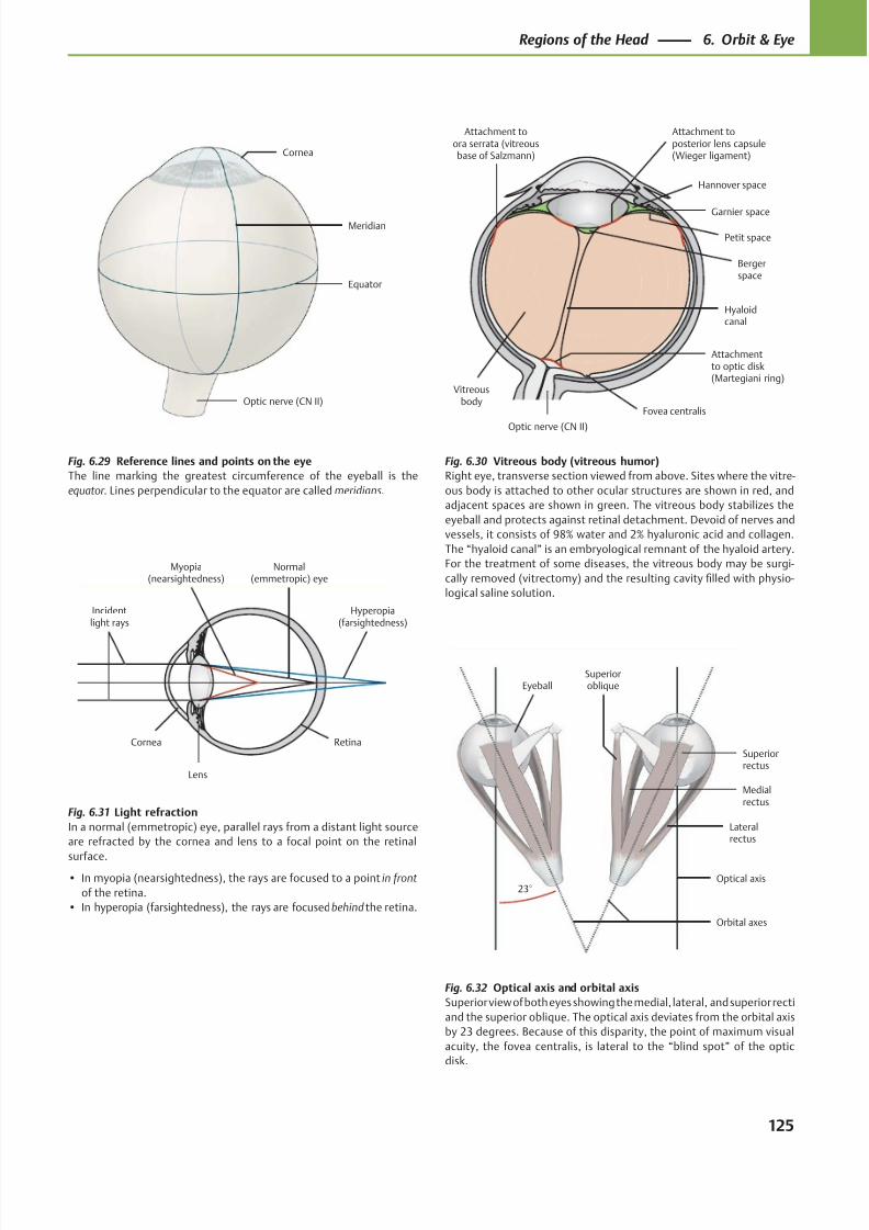
8/15/2019 Head and Neck Anatomy for Dental Medicine - Thieme; (January 26, 2010)
http://slidepdf.com/reader/full/head-and-neck-anatomy-for-dental-medicine-thieme-january-26-2010 138/384
Optic nerve (CN II)
Equator
Meridian
Cornea
Hannover space
Attachment toora serrata (vitreousbase of Salzmann)
Bergerspace
Attachmentto optic disk(Martegiani ring)
Optic nerve (CN II)
Hyaloidcanal
Vitreousbody
Petit space
Garnier space
Attachment toposterior lens capsule(Wieger ligament)
Fovea centralis
Lens
Incidentlight rays
Cornea
Myopia(nearsightedness)
Hyperopia(farsightedness)
Retina
Normal(emmetropic) eye
Eyeball
Orbital axes
Optical axis
Lateralrectus
Superiorrectus
Medialrectus
Superioroblique
23°
Fig. 6.29 Reference lines and points on the eye
The line marking the greatest circumference of the eyeball is the
equator. Lines perpendicular to the equator are called meridians.
Fig. 6.30 Vitreous body (vitreous humor)
Right eye, transverse section viewed from above. Sites where the vitre-
ous body is attached to other ocular structures are shown in red, and
adjacent spaces are shown in green. The vitreous body stabilizes the
eyeball and protects against retinal detachment. Devoid of nerves and
vessels, it consists of 98% water and 2% hyaluronic acid and collagen.
The “hyaloid canal” is an embryological remnant of the hyaloid artery.
For the treatment of some diseases, the vitreous body may be surgi-
cally removed (vitrectomy) and the resulting cavity filled with physio-
logical saline solution.
Fig. 6.31 Light refraction
In a normal (emmetropic) eye, parallel rays from a distant light source
are refracted by the cornea and lens to a focal point on the retinal
surface.• In myopia (nearsightedness), the rays are focused to a point in front
of the retina.
• In hyperopia (farsightedness), the rays are focused behind the retina.
Fig. 6.32 Optical axis and orbital axis
Superior view of both eyes showing the medial, lateral, and superior recti
and the superior oblique. The optical axis deviates from the orbital axis
by 23 degrees. Because of this disparity, the point of maximum visual
acuity, the fovea centralis, is lateral to the “blind spot” of the optic
disk.
125
Regions of the Head 6. Orbit & Eye
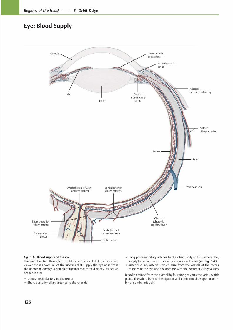
8/15/2019 Head and Neck Anatomy for Dental Medicine - Thieme; (January 26, 2010)
http://slidepdf.com/reader/full/head-and-neck-anatomy-for-dental-medicine-thieme-january-26-2010 139/384
Long posteriorciliary arteries
Lens
Lesser arterial
circle of iris
Greaterarterial circle
of iris
Anteriorconjunctival artery
Retina
Arterial circle of Zinn(and von Haller)
Short posteriorciliary arteries
Pial vascularplexus
Vorticose vein
Sclera
Anteriorciliary arteries
Scleral venoussinus
Iris
Cornea
Choroid(choroido-
capillary layer)
Optic nerve
Central retinalartery and vein
Fig. 6.33 Blood supply of the eye
Horizontal section through the right eye at the level of the optic nerve,
viewed from above. All of the arteries that supply the eye arise from
the ophthalmic artery, a branch of the internal carotid artery. Its ocular
branches are:
• Central retinal artery to the retina
• Short posterior ciliary arteries to the choroid
• Long posterior ciliary arteries to the ciliary body and iris, where they
supply the greater and lesser arterial circles of the iris (see Fig. 6.43)
• Anterior ciliary arteries, which arise from the vessels of the rectus
muscles of the eye and anastomose with the posterior ciliary vessels
Blood is drained from the eyeball by four to eight vorticose veins, which
pierce the sclera behind the equator and open into the superior or in-
ferior ophthalmic vein.
126
Regions of the Head 6. Orbit & Eye
Eye: Blood Supply
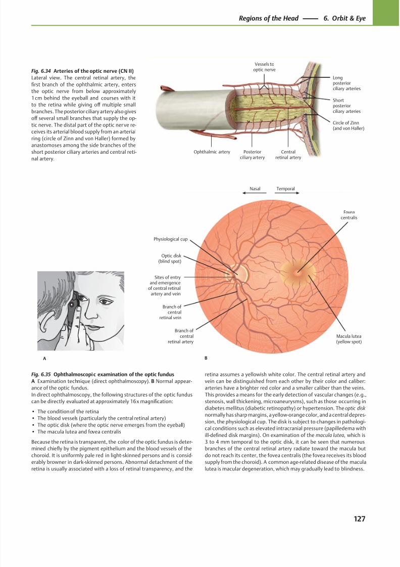
8/15/2019 Head and Neck Anatomy for Dental Medicine - Thieme; (January 26, 2010)
http://slidepdf.com/reader/full/head-and-neck-anatomy-for-dental-medicine-thieme-january-26-2010 140/384
Vessels tooptic nerve
Ophthalmic artery
Shortposteriorciliary arteries
Longposteriorciliary arteries
Centralretinal artery
Posteriorciliary artery
Circle of Zinn(and von Haller)
TemporalNasal
Physiological cup
Sites of entryand emergence
of central retinalartery and vein
Optic disk(blind spot)
Branch of central
retinal vein
Branch of central
retinal artery
Foveacentralis
Macula lutea(yellow spot)
BA
Fig. 6.34 Arteries of the optic nerve (CN II)
Lateral view. The central retinal artery, the
first branch of the ophthalmic artery, enters
the optic nerve from below approximately
1 cm behind the eyeball and courses with itto the retina while giving off multiple small
branches. The posterior ciliary artery also gives
off several small branches that supply the op-
tic nerve. The distal part of the optic nerve re-
ceives its arterial blood supply from an arterial
ring (circle of Zinn and von Haller) formed by
anastomoses among the side branches of the
short posterior ciliary arteries and central reti-
nal artery.
Fig. 6.35 Ophthalmoscopic examination of the optic fundus
A Examination technique (direct ophthalmoscopy). B Normal appear-
ance of the optic fundus.
In direct ophthalmoscopy, the following structures of the optic funduscan be directly evaluated at approximately 16 x magnification:
• The condition of the retina
• The blood vessels (particularly the central retinal artery)
• The optic disk (where the optic nerve emerges from the eyeball)
• The macula lutea and fovea centralis
Because the retina is transparent, the color of the optic fundus is deter-
mined chiefly by the pigment epithelium and the blood vessels of the
choroid. It is uniformly pale red in light-skinned persons and is consid-
erably browner in dark-skinned persons. Abnormal detachment of the
retina is usually associated with a loss of retinal transparency, and the
retina assumes a yellowish white color. The central retinal artery and
vein can be distinguished from each other by their color and caliber:
arteries have a brighter red color and a smaller caliber than the veins.
This provides a means for the early detection of vascular changes (e.g.,stenosis, wall thickening, microaneurysms), such as those occurring in
diabetes mellitus (diabetic retinopathy) or hypertension. The optic disk
normally has sharp margins, a yellow-orange color, and a central depres-
sion, the physiological cup. The disk is subject to changes in pathologi-
cal conditions such as elevated intracranial pressure (papilledema with
ill-defined disk margins). On examination of the macula lutea, which is
3 to 4 mm temporal to the optic disk, it can be seen that numerous
branches of the central retinal artery radiate toward the macula but
do not reach its center, the fovea centralis (the fovea receives its blood
supply from the choroid). A common age-related disease of the macula
lutea is macular degeneration, which may gradually lead to blindness.
127
Regions of the Head 6. Orbit & Eye
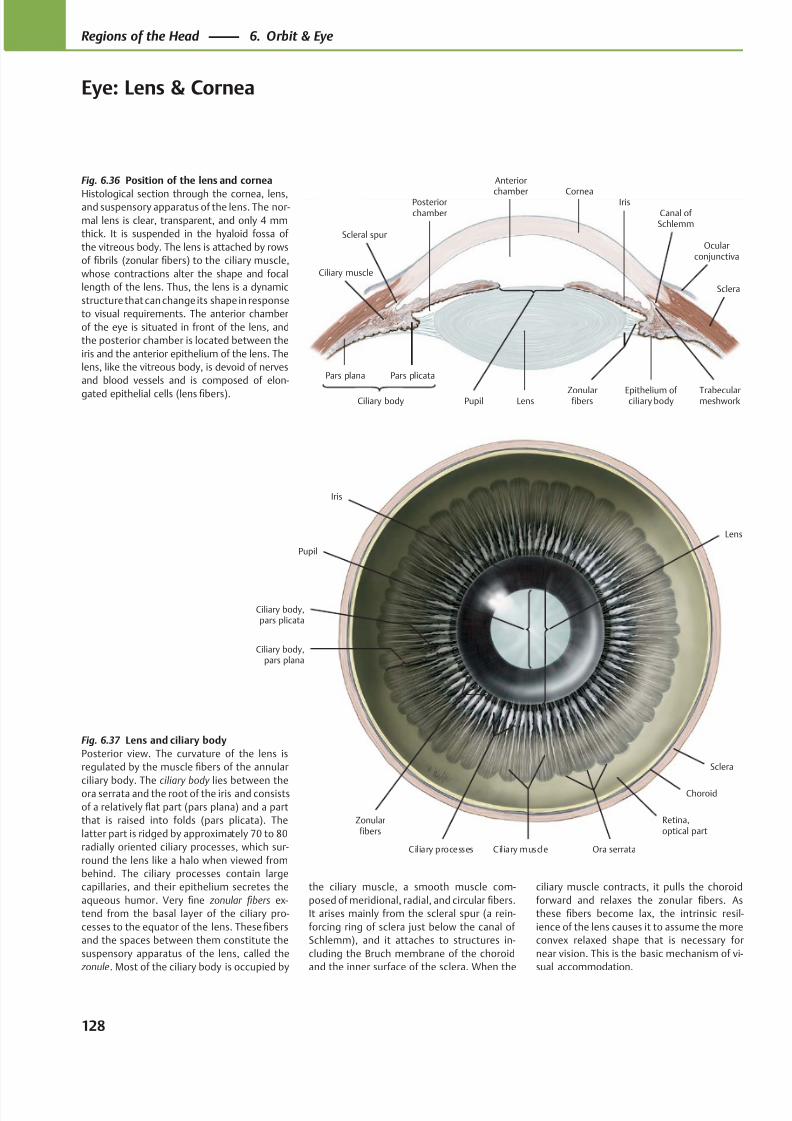
8/15/2019 Head and Neck Anatomy for Dental Medicine - Thieme; (January 26, 2010)
http://slidepdf.com/reader/full/head-and-neck-anatomy-for-dental-medicine-thieme-january-26-2010 141/384
Anterior
chamberPosteriorchamber
Ciliary muscle
Sclera
Canal of Schlemm
Ocularconjunctiva
Scleral spur
IrisCornea
LensCiliary body
Pars plana Pars plicata
Trabecularmeshwork
Epithelium of ciliary body
ZonularfibersPupil
Iris
Choroid
Sclera
Zonularfibers
Ciliary processes Ciliary muscle
Ciliary body,pars plana
Ciliary body,pars plicata
Ora serrata
Retina,optical part
Lens
Pupil
Fig. 6.36 Position of the lens and cornea
Histological section through the cornea, lens,and suspensory apparatus of the lens. The nor-
mal lens is clear, transparent, and only 4 mm
thick. It is suspended in the hyaloid fossa of
the vitreous body. The lens is attached by rows
of fibrils (zonular fibers) to the ciliary muscle,
whose contractions alter the shape and focal
length of the lens. Thus, the lens is a dynamic
structure that can change its shape in response
to visual requirements. The anterior chamber
of the eye is situated in front of the lens, and
the posterior chamber is located between the
iris and the anterior epithelium of the lens. The
lens, like the vitreous body, is devoid of nerves
and blood vessels and is composed of elon-
gated epithelial cells (lens fibers).
Fig. 6.37 Lens and ciliary body
Posterior view. The curvature of the lens is
regulated by the muscle fibers of the annular
ciliary body. The ciliary body lies between theora serrata and the root of the iris and consists
of a relatively flat part (pars plana) and a part
that is raised into folds (pars plicata). The
latter part is ridged by approximately 70 to 80
radially oriented ciliary processes, which sur-
round the lens like a halo when viewed from
behind. The ciliary processes contain large
capillaries, and their epithelium secretes the
aqueous humor. Very fine zonular fibers ex-
tend from the basal layer of the ciliary pro-
cesses to the equator of the lens. These fibers
and the spaces between them constitute the
suspensory apparatus of the lens, called the
zonule. Most of the ciliary body is occupied by
the ciliary muscle, a smooth muscle com-
posed of meridional, radial, and circular fibers.
It arises mainly from the scleral spur (a rein-
forcing ring of sclera just below the canal of
Schlemm), and it attaches to structures in-
cluding the Bruch membrane of the choroid
and the inner surface of the sclera. When the
ciliary muscle contracts, it pulls the choroid
forward and relaxes the zonular fibers. As
these fibers become lax, the intrinsic resil-
ience of the lens causes it to assume the more
convex relaxed shape that is necessary for
near vision. This is the basic mechanism of vi-
sual accommodation.
128
Regions of the Head 6. Orbit & Eye
Eye: Lens & Cornea
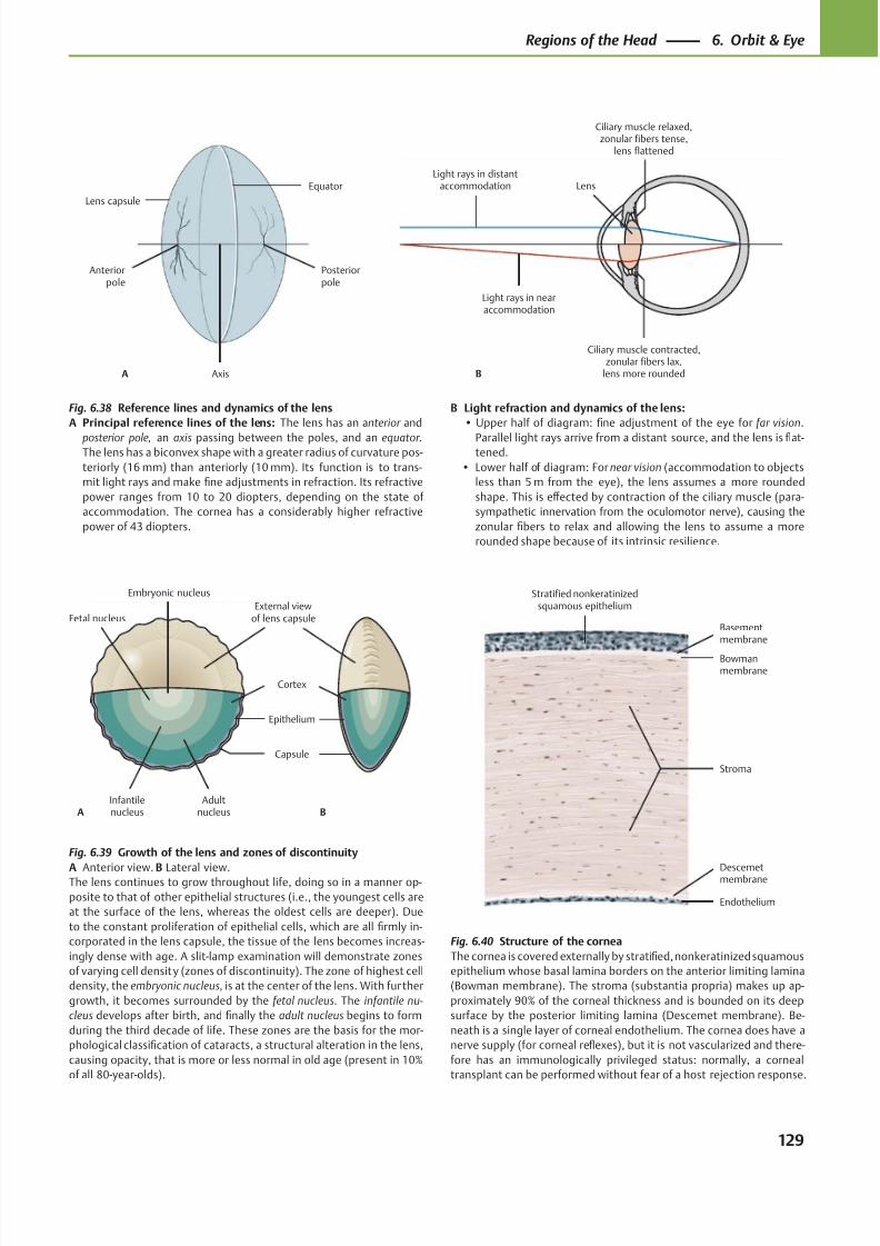
8/15/2019 Head and Neck Anatomy for Dental Medicine - Thieme; (January 26, 2010)
http://slidepdf.com/reader/full/head-and-neck-anatomy-for-dental-medicine-thieme-january-26-2010 142/384
Anteriorpole
Axis
Posteriorpole
A
Equator
Lens capsule
Light rays in distantaccommodation
Light rays in nearaccommodation
Lens
Ciliary muscle contracted,zonular fibers lax,
lens more rounded
Ciliary muscle relaxed,zonular fibers tense,
lens flattened
B
Embryonic nucleus
Fetal nucleus
Infantilenucleus
Adultnucleus
Capsule
Cortex
External viewof lens capsule
A B
Epithelium
Endothelium
Descemetmembrane
Bowmanmembrane
Basementmembrane
Stratified nonkeratinizedsquamous epithelium
Stroma
Fig. 6.38 Reference lines and dynamics of the lens
A Principal reference lines of the lens: The lens has an anterior and
posterior pole, an axis passing between the poles, and an equator .The lens has a biconvex shape with a greater radius of curvature pos-
teriorly (16 mm) than anteriorly (10 mm). Its function is to trans-
mit light rays and make fine adjustments in refraction. Its refractive
power ranges from 10 to 20 diopters, depending on the state of
accommodation. The cornea has a considerably higher refractive
power of 43 diopters.
Fig. 6.39 Growth of the lens and zones of discontinuity
A Anterior view. B Lateral view.The lens continues to grow throughout life, doing so in a manner op-
posite to that of other epithelial structures (i.e., the youngest cells are
at the surface of the lens, whereas the oldest cells are deeper). Due
to the constant proliferation of epithelial cells, which are all firmly in-
corporated in the lens capsule, the tissue of the lens becomes increas-
ingly dense with age. A slit-lamp examination will demonstrate zones
of varying cell density (zones of discontinuity). The zone of highest cell
density, the embryonic nucleus, is at the center of the lens. With further
growth, it becomes surrounded by the fetal nucleus. The infantile nu-
cleus develops after birth, and finally the adult nucleus begins to form
during the third decade of life. These zones are the basis for the mor-
phological classification of cataracts, a structural alteration in the lens,
causing opacity, that is more or less normal in old age (present in 10%
of all 80-year-olds).
Fig. 6.40 Structure of the cornea
The cornea is covered externally by stratified, nonkeratinized squamous
epithelium whose basal lamina borders on the anterior limiting lamina
(Bowman membrane). The stroma (substantia propria) makes up ap-
proximately 90% of the corneal thickness and is bounded on its deep
surface by the posterior limiting lamina (Descemet membrane). Be-
neath is a single layer of corneal endothelium. The cornea does have a
nerve supply (for corneal reflexes), but it is not vascularized and there-
fore has an immunologically privileged status: normally, a corneal
transplant can be performed without fear of a host rejection response.
B Light refraction and dynamics of the lens:
• Upper half of diagram: fine adjustment of the eye for far vision.
Parallel light rays arrive from a distant source, and the lens is flat-tened.
• Lower half of diagram: For near vision (accommodation to objects
less than 5 m from the eye), the lens assumes a more rounded
shape. This is eff ected by contraction of the ciliary muscle (para-
sympathetic innervation from the oculomotor nerve), causing the
zonular fibers to relax and allowing the lens to assume a more
rounded shape because of its intrinsic resilience.
129
Regions of the Head 6. Orbit & Eye
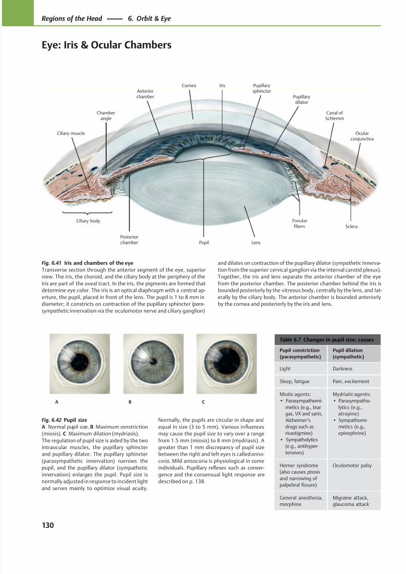
8/15/2019 Head and Neck Anatomy for Dental Medicine - Thieme; (January 26, 2010)
http://slidepdf.com/reader/full/head-and-neck-anatomy-for-dental-medicine-thieme-january-26-2010 143/384
Anteriorchamber
Posteriorchamber
Canal of Schlemm
Ciliary body
Chamberangle
Pupil Lens
Zonularfibers
Ciliary muscle
Sclera
Ocularconjunctiva
Pupillarydilator
Pupillarysphincter
IrisCornea
A B C
Table 6.7 Changes in pupil size: causes
Pupil constriction
(parasympathetic)
Pupil dilation
(sympathetic)
Light Darkness
Sleep, fatigue Pain, excitement
Miotic agents:
• Parasympathomi-metics (e.g., tear
gas, VX and sarin,
Alzheimer’s
drugs such as
rivastigmine)
• Sympatholytics
(e.g., antihyper-
tensives)
Mydriatic agents:
• Parasympatho-lytics (e.g.,
atropine)
• Sympathomi-
metics (e.g.,
epinephrine)
Horner syndrome
(also causes ptosis
and narrowing of
palpebral fissure)
Oculomotor palsy
General anesthesia,
morphine
Migraine attack,
glaucoma attack
Fig. 6.41 Iris and chambers of the eye
Transverse section through the anterior segment of the eye, superior
view. The iris, the choroid, and the ciliary body at the periphery of the
iris are part of the uveal tract. In the iris, the pigments are formed that
determine eye color. The iris is an optical diaphragm with a central ap-
erture, the pupil, placed in front of the lens. The pupil is 1 to 8 mm in
diameter; it constricts on contraction of the pupillary sphincter ( para-
sympathetic innervation via the oculomotor nerve and ciliary ganglion)
Fig. 6.42 Pupil size
A Normal pupil size. B Maximum constriction
(miosis). C Maximum dilation (mydriasis).
The regulation of pupil size is aided by the two
intraocular muscles, the pupillary sphincter
and pupillary dilator. The pupillary sphincter
(parasympathetic innervation) narrows the
pupil, and the pupillary dilator (sympathetic
innervation) enlarges the pupil. Pupil size is
normally adjusted in response to incident light
and serves mainly to optimize visual acuity.
and dilates on contraction of the pupillary dilator (sympathetic innerva-
tion from the superior cervical ganglion via the internal carotid plexus).
Together, the iris and lens separate the anterior chamber of the eye
from the posterior chamber. The posterior chamber behind the iris is
bounded posteriorly by the vitreous body, centrally by the lens, and lat-
erally by the ciliary body. The anterior chamber is bounded anteriorly
by the cornea and posteriorly by the iris and lens.
Normally, the pupils are circular in shape and
equal in size (3 to 5 mm). Various influences
may cause the pupil size to vary over a range
from 1.5 mm (miosis) to 8 mm (mydriasis). A
greater than 1 mm discrepancy of pupil size
between the right and left eyes is called aniso-
coria. Mild anisocoria is physiological in some
individuals. Pupillary reflexes such as conver-
gence and the consensual light response are
described on p. 138.
130
Regions of the Head 6. Orbit & Eye
Eye: Iris & Ocular Chambers
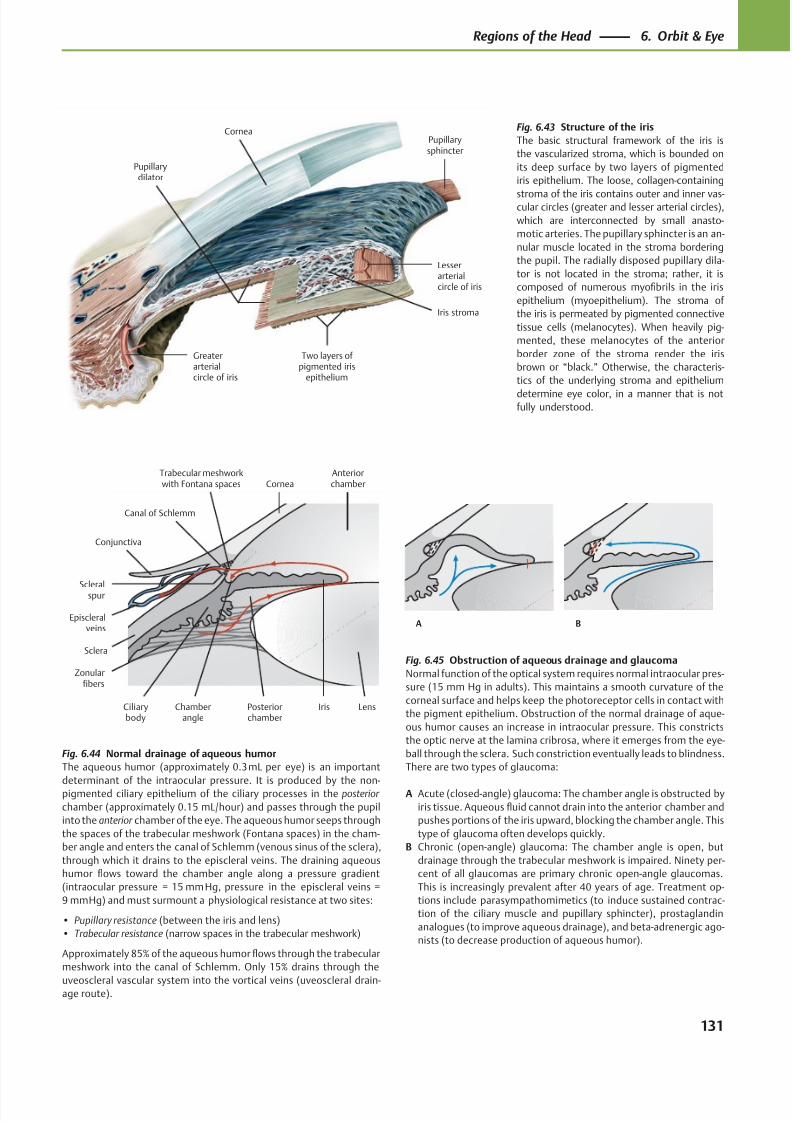
8/15/2019 Head and Neck Anatomy for Dental Medicine - Thieme; (January 26, 2010)
http://slidepdf.com/reader/full/head-and-neck-anatomy-for-dental-medicine-thieme-january-26-2010 144/384
CorneaPupillarysphincter
Iris stroma
Two layers of pigmented iris
epithelium
Greaterarterialcircle of iris
Pupillarydilator
Lesserarterialcircle of iris
Canal of Schlemm
Scleralspur
Conjunctiva
Episcleralveins
Sclera
Ciliarybody
Zonularfibers
Chamberangle
Posteriorchamber
LensIris
AnteriorchamberCornea
Trabecular meshworkwith Fontana spaces
A B
Fig. 6.43 Structure of the iris
The basic structural framework of the iris is
the vascularized stroma, which is bounded on
its deep surface by two layers of pigmented
iris epithelium. The loose, collagen-containing
stroma of the iris contains outer and inner vas-cular circles (greater and lesser arterial circles),
which are interconnected by small anasto-
motic arteries. The pupillary sphincter is an an-
nular muscle located in the stroma bordering
the pupil. The radially disposed pupillary dila-
tor is not located in the stroma; rather, it is
composed of numerous myofibrils in the iris
epithelium (myoepithelium). The stroma of
the iris is permeated by pigmented connective
tissue cells (melanocytes). When heavily pig-
mented, these melanocytes of the anterior
border zone of the stroma render the iris
brown or “black.” Otherwise, the characteris-
tics of the underlying stroma and epithelium
determine eye color, in a manner that is notfully understood.
Fig. 6.44 Normal drainage of aqueous humor
The aqueous humor (approximately 0.3 mL per eye) is an important
determinant of the intraocular pressure. It is produced by the non-pigmented ciliary epithelium of the ciliary processes in the posterior
chamber (approximately 0.15 mL/hour) and passes through the pupil
into the anterior chamber of the eye. The aqueous humor seeps through
the spaces of the trabecular meshwork (Fontana spaces) in the cham-
ber angle and enters the canal of Schlemm (venous sinus of the sclera),
through which it drains to the episcleral veins. The draining aqueous
humor flows toward the chamber angle along a pressure gradient
(intraocular pressure = 15 mm Hg, pressure in the episcleral veins =
9 mm Hg) and must surmount a physiological resistance at two sites:
• Pupillary resistance (between the iris and lens)
• Trabecular resistance (narrow spaces in the trabecular meshwork)
Approximately 85% of the aqueous humor flows through the trabecular
meshwork into the canal of Schlemm. Only 15% drains through the
uveoscleral vascular system into the vortical veins (uveoscleral drain-age route).
Fig. 6.45 Obstruction of aqueous drainage and glaucoma
Normal function of the optical system requires normal intraocular pres-
sure (15 mm Hg in adults). This maintains a smooth curvature of the
corneal surface and helps keep the photoreceptor cells in contact with
the pigment epithelium. Obstruction of the normal drainage of aque-
ous humor causes an increase in intraocular pressure. This constricts
the optic nerve at the lamina cribrosa, where it emerges from the eye-
ball through the sclera. Such constriction eventually leads to blindness.
There are two types of glaucoma:
A Acute (closed-angle) glaucoma: The chamber angle is obstructed by
iris tissue. Aqueous fluid cannot drain into the anterior chamber and
pushes portions of the iris upward, blocking the chamber angle. This
type of glaucoma often develops quickly.
B Chronic (open-angle) glaucoma: The chamber angle is open, but
drainage through the trabecular meshwork is impaired. Ninety per-
cent of all glaucomas are primary chronic open-angle glaucomas.
This is increasingly prevalent after 40 years of age. Treatment op-
tions include parasympathomimetics (to induce sustained contrac-
tion of the ciliary muscle and pupillary sphincter), prostaglandin
analogues (to improve aqueous drainage), and beta-adrenergic ago-
nists (to decrease production of aqueous humor).
131
Regions of the Head 6. Orbit & Eye
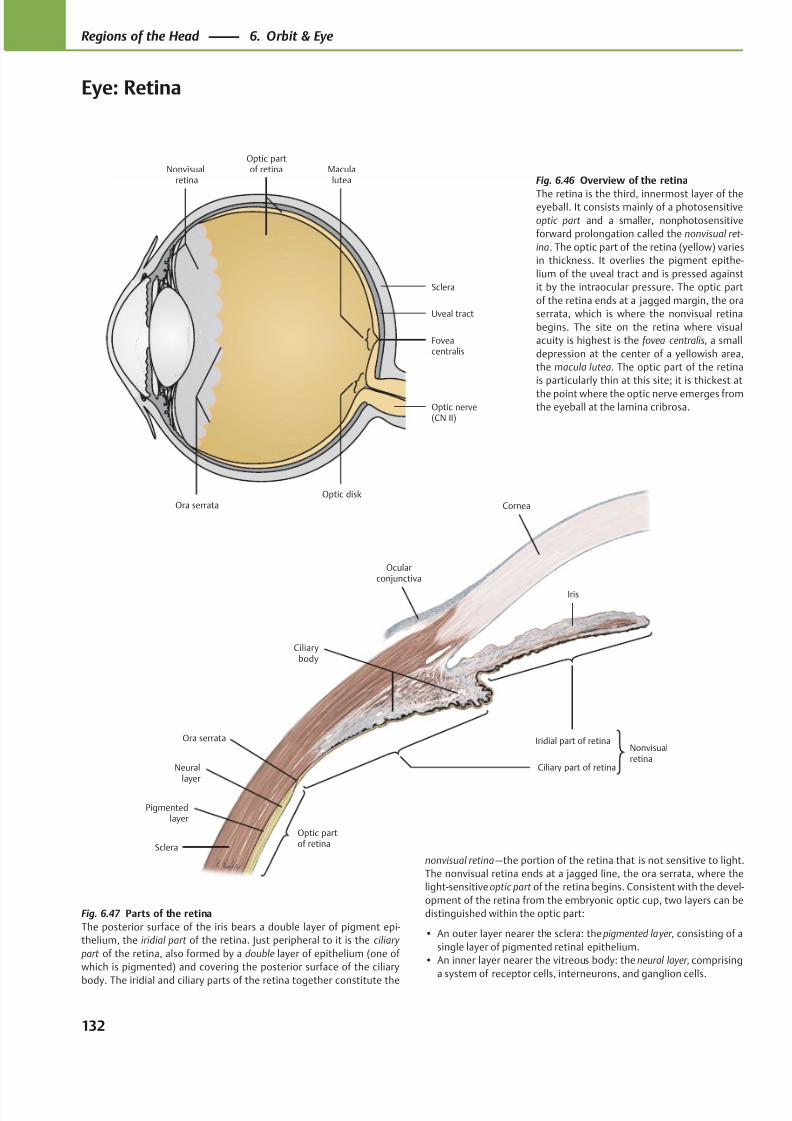
8/15/2019 Head and Neck Anatomy for Dental Medicine - Thieme; (January 26, 2010)
http://slidepdf.com/reader/full/head-and-neck-anatomy-for-dental-medicine-thieme-january-26-2010 145/384
Ciliarybody
Ora serrata
Optic partof retina
Ciliary part of retina
Nonvisualretina
Iridial part of retina
Cornea
Sclera
Pigmentedlayer
Neurallayer
Iris
Ocularconjunctiva
Ora serrata
Maculalutea
Optic disk
Optic nerve(CN II)
Foveacentralis
Sclera
Uveal tract
Optic partof retinaNonvisual
retina Fig. 6.46 Overview of the retina
The retina is the third, innermost layer of theeyeball. It consists mainly of a photosensitive
optic part and a smaller, nonphotosensitive
forward prolongation called the nonvisual ret-
ina. The optic part of the retina (yellow) varies
in thickness. It overlies the pigment epithe-
lium of the uveal tract and is pressed against
it by the intraocular pressure. The optic part
of the retina ends at a jagged margin, the ora
serrata, which is where the nonvisual retina
begins. The site on the retina where visual
acuity is highest is the fovea centralis, a small
depression at the center of a yellowish area,
the macula lutea. The optic part of the retina
is particularly thin at this site; it is thickest at
the point where the optic nerve emerges fromthe eyeball at the lamina cribrosa.
Fig. 6.47 Parts of the retina
The posterior surface of the iris bears a double layer of pigment epi-
thelium, the iridial part of the retina. Just peripheral to it is the ciliary
part of the retina, also formed by a double layer of epithelium (one of
which is pigmented) and covering the posterior surface of the ciliary
body. The iridial and ciliary parts of the retina together constitute the
nonvisual retina —the portion of the retina that is not sensitive to light.
The nonvisual retina ends at a jagged line, the ora serrata, where the
light-sensitive optic part of the retina begins. Consistent with the devel-
opment of the retina from the embryonic optic cup, two layers can be
distinguished within the optic part:
• An outer layer nearer the sclera: the pigmented layer, consisting of a
single layer of pigmented retinal epithelium.
• An inner layer nearer the vitreous body: the neural layer, comprising
a system of receptor cells, interneurons, and ganglion cells.
132
Regions of the Head 6. Orbit & Eye
Eye: Retina
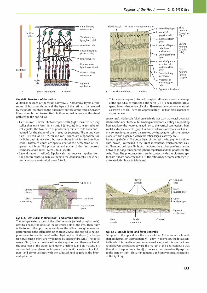
8/15/2019 Head and Neck Anatomy for Dental Medicine - Thieme; (January 26, 2010)
http://slidepdf.com/reader/full/head-and-neck-anatomy-for-dental-medicine-thieme-january-26-2010 146/384
Müllercells Pigment
epithelium
Bruch membrane Choroid
Outer limitingmembrane
First neurons(photoreceptors)
Horizontal cell
Second neurons(bipolar cells)
Amacrine cells
Third neurons(ganglion cells)
Inner limitingmembrane
Excitation
Incidentlight
A
Blood vessels
ChoroidBruch membrane1. Pigment epithelium
2. Processes ofphotoreceptor
cells
3. Outer limitingmembrane
4. Nuclei of photo- receptor cells
(outer nuclearlayer)
5. Outer plexiformlayer
6. Nuclei of bipolarcells (inner
nuclear layer)
7. Inner plexiformlayer
8. Nuclei ofganglion cells
9. Nerve fiber layer10. Inner limiting membrane
B
Thirdneurons(ganglioncells)
Secondneurons(bipolarcells)
Firstneurons(photo-receptors)
Optic disk
Laminacribrosa
Subarachnoidspace
MeningesCentralretinal artery
Foveacentralis
Bloodvessels
Bruchmembrane
Pigmentepithelium
Outernuclear layer
Innernuclear layer
Ganglioncells
Choroid
Fig. 6.48 Structure of the retina
A Retinal neurons of the visual pathway. B Anatomical layers of theretina. Light passes through all the layers of the retina to be received
by the photoreceptors on the outermost surface of the retina. Sensory
information is then transmitted via three retinal neurons of the visual
pathway to the optic disk:
• First neurons (pink): Photoreceptor cells (light-sensitive sensory
cells) that transform light stimuli (photons) into electrochemi-
cal signals. The two types of photoreceptors are rods and cones,
named for the shape of their receptor segment. The retina con-
tains 100 million to 125 million rods, which are responsible for
twilight and night vision, but only about 6 million to 7 million
cones. Different cones are specialized for the perception of red,
green, and blue. The processes and nuclei of the first neurons
compose anatomical layers 2 to 4 (see B).
• Second neurons (yellow): Bipolar cells that receive impulses fromthe photoreceptors and relay them to the ganglion cells. These neu-
rons compose anatomical layers 5 to 7.
Fig. 6.49 Optic disk (“blind spot”) and lamina cribrosa
The unmyelinated axons of the third neurons (retinal ganglion cells)
pass to a collecting point at the posterior pole of the eye. There they
unite to form the optic nerve and leave the retina through numerous
perforations in the sclera (lamina cribrosa). (Note: The optic disk has no
photoreceptors and is therefore the physiological blind spot.) In the op-
tic nerve, these axons are myelinated by oligodendrocytes. The optic
nerve (CN II) is an extension of the diencephalon and therefore has all
the coverings of the brain (dura mater, arachnoid, and pia mater). It is
surrounded by a subarachnoid space that contains cerebrospinal fluid
(CSF) and communicates with the subarachnoid spaces of the brain
and spinal cord.
Fig. 6.50 Macula lutea and fovea centralis
Temporal to the optic disk is the macula lutea. At its center is a funnel-
shaped depression approximately 1.5 mm in diameter, the fovea cen-
tralis, which is the site of maximum visual acuity. At this site the inner
retinal layers are heaped toward the margin of the depression, so that
the cells of the photoreceptors (just cones, no rods) are directly exposed
to the incident light. This arrangement significantly reduces scattering
of the light rays.
• Third neurons (green): Retinal ganglion cells whose axons converge
at the optic disk to form the optic nerve (CN II) and reach the lateralgeniculate and superior colliculus. These neurons compose anatomi-
cal layers 8 to 10. There are approximately 1 million retinal ganglion
axons per eye.
Support cells: Müller cells (blue) are glial cells that span the neural layer radi-
ally from the inner to the outer limiting membranes, creating a supporting
framework for the neurons. In addition to the vertical connections, hori-
zontal and amacrine cells (gray) function as interneurons that establish lat-
eral connections. Impulses transmitted by the receptor cells are thereby
processed and organized within the retina (signal convergence).
Pigment epithelium: The outer layer of the retina (the pigment epithe-
lium, brown) is attached to the Bruch membrane, which contains elas-
tic fibers and collagen fibrils and mediates the exchange of substances
between the adjacent choroid (choriocapillaris) and the photoreceptor
cells. Note: The photoreceptors are in contact with the pigment epi-thelium but are not attached to it. The retina may become detached (if
untreated, this leads to blindness).
133
Regions of the Head 6. Orbit & Eye
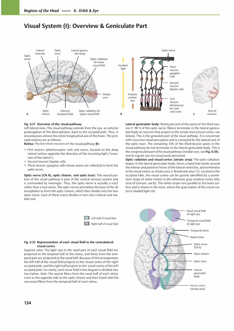
8/15/2019 Head and Neck Anatomy for Dental Medicine - Thieme; (January 26, 2010)
http://slidepdf.com/reader/full/head-and-neck-anatomy-for-dental-medicine-thieme-january-26-2010 147/384
Opticnerve
Opticchiasm
Anteriortemporal lobe
Optic radiation forupper visual field
Striatearea
Optic radiationfor lower
visual field
Lateral genicu-late body
Optictract
A
Lateralventricle
Thirdneuron:ganglioncells
Secondneuron:bipolar cells
Firstneuron:photorecep-tor rodsand cones
Incidentlight
Optic nerve
B
Impulseconduc-
tion
Stria of GennariC
Visual cortex
(striate area)
Lateralgeniculatebody
Optic tract
Optic chiasm
Optic nerve(CN II)
Temporal retina
Nasal retina
Nasal visual fieldof right eye
Temporal visual fieldof right eye
Left half of visual field
Right half of visual field
Fig. 6.51 Overview of the visual pathway
Left lateral view. The visual pathway extends from the eye, an anterior
prolongation of the diencephalon, back to the occipital pole. Thus, it
encompasses almost the entire longitudinal axis of the brain. The prin-
cipal stations are as follows:
Retina: The first three neurons of the visual pathway (B):
• First neuron: photoreceptor rods and cones, located on the deep
retinal surface opposite the direction of the incoming light (“inver-
sion of the retina”).
• Second neuron: bipolar cells.
• Third neuron: ganglion cells whose axons are collected to form the
optic nerve.
Optic nerve (CN II), optic chiasm, and optic tract: This neural por-
tion of the visual pathway is part of the central nervous system and
is surrounded by meninges. Thus, the optic nerve is actually a tract
rather than a true nerve. The optic nerves join below the base of the di-
encephalon to form the optic chiasm, which then divides into the two
optic tracts. Each of these tracts divides in turn into a lateral and me-
dial root.
Fig. 6.52 Representation of each visual field in the contralateral
visual cortex
Superior view. The light rays in the nasal part of each visual field are
projected to the temporal half of the retina, and those from the tem-
poral part are projected to the nasal half. Because of this arrangement,
the left half of the visual field projects to the visual cortex of the right
occipital pole, and the right half projects to the visual cortex of the lef t
occipital pole. For clarity, each visual field in the diagram is divided into
two halves. Note: The axonal fibers from the nasal half of each retina
cross to the opposite side at the optic chiasm and then travel with the
uncrossed fibers from the temporal half of each retina.
Lateral geniculate body: Ninety percent of the axons of the third neu-
ron (= 90 % of the optic nerve fibers) terminate in the lateral genicu-
late body on neurons that project to the striate area (visual cortex, see
below). This is the geniculate part of the visual pathway . It is concerned
with conscious visual perception and is conveyed by the lateral root of
the optic tract. The remaining 10% of the third-neuron axons in the
visual pathway do not terminate in the lateral geniculate body. This is
the nongeniculate part of the visual pathway (medial root, see Fig. 6.56),
and its signals are not consciously perceived.
Optic radiation and visual cortex (striate area): The optic radiation
begins in the lateral geniculate body, forms a band that winds around
the inferior and posterior horns of the lateral ventricles, and terminates
in the visual cortex or striate area (= Brodmann area 17). Located in the
occipital lobe, the visual cortex can be grossly identified by a promi-
nent stripe of white matter in the otherwise gray cerebral cortex (the
stria of Gennari, see C). This white stripe runs parallel to the brain sur-
face and is shown in the inset, where the gray matter of the visual cor-
tex is shaded light red.
134
Regions of the Head 6. Orbit & Eye
Visual System (I): Overview & Geniculate Part
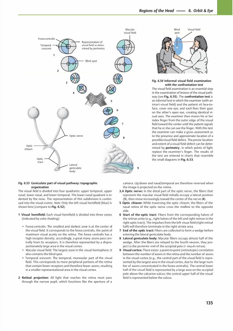
8/15/2019 Head and Neck Anatomy for Dental Medicine - Thieme; (January 26, 2010)
http://slidepdf.com/reader/full/head-and-neck-anatomy-for-dental-medicine-thieme-january-26-2010 148/384
Fovea centralis
Macularvisual field
Temporalcrescent
1
2
3
4
Opticchiasm
Optictract
Lateralgeniculatebody
9
8
7
6
5
Blind spot
Representation of visual field as deter-mined by perimetry
Optic nerve
Visual fieldBlindspot
Fig. 6.54 Informal visual field examination
with the confrontation test
The visual field examination is an essential step
in the examination of lesions of the visual path-
way (see Fig. 6.55). The confrontation test is
an informal test in which the examiner (with an
intact visual field) and the patient sit face-to-
face, cover one eye, and each fixes their gaze
on the other’s open eye, creating identical vi-
sual axes. The examiner then moves his or herindex finger from the outer edge of the visual
field toward the center until the patient signals
that he or she can see the finger. With this test
the examiner can make a gross assessment as
to the presence and approximate location of a
possible visual field defect. The precise location
and extent of a visual field defect can be deter-
mined by perimetry, in which points of light
replace the examiner’s finger. The results of
the test are entered in charts that resemble
the small diagrams in Fig. 6.53.
Fig. 6.53 Geniculate part of visual pathway: topographic
organization
The visual field is divided into four quadrants: upper temporal, upper
nasal, lower nasal, and lower temporal. The lower nasal quadrant is in-
dented by the nose. The representation of this subdivision is contin-
ued into the visual cortex. Note: Only the left visual hemifield (blue) is
shown here (compare to Fig. 6.52).
1 Visual hemifield: Each visual hemifield is divided into three zones
(indicated by color shading):
• Fovea centralis: The smallest and darkest zone is at the center of
the visualfi
eld. It corresponds to the fovea centralis, the point ofmaximum visual acuity on the retina. The fovea centralis has a
high receptor density; accordingly, a great many axons pass cen-
trally from its receptors. It is therefore represented by a dispro-
portionately large area in the visual cortex.
• Macular visual field: The largest zone in the visual hemisphere; it
also contains the blind spot.
• Temporal crescent: The temporal, monocular part of the visual
field. This corresponds to more peripheral portions of the retina
that contain fewer receptors and therefore fewer axons, resulting
in a smaller representational area in the visual cortex.
2 Retinal projection: All light that reaches the retina must pass
through the narrow pupil, which functions like the aperture of a
camera. Up/down and nasal/temporal are therefore reversed when
the image is projected on the retina.
3,4 Optic nerve: In the distal part of the optic nerve, the fibers that
represent the macular visual field initially occupy a lateral position
(3), then move increasingly toward the center of the ner ve (4).
5 Optic chiasm: While traversing the optic chiasm, the fibers of the
nasal retina of the optic nerve cross the midline to the opposite
side.
6 Start of the optic tract: Fibers from the corresponding halves of
the retinas unite (e.g., right halves of the left and right retinas in the
right optic tract). The impulses from the left visual field (right retinal
half) will therefore terminate in the right striate area.
7 End of the optic tract: Fibers are collected to form a wedge beforeentering the lateral geniculate body.
8 Lateral geniculate body: Macular fibers occupy almost half of the
wedge. After the fibers are relayed to the fourth neuron, they pro-
ject to the posterior end of the occipital pole (= visual cortex).
9 Visual cortex: There exists a point-to-point (retinotopic) correlation
between the number of axons in the retina and the number of axons
in the visual cortex (e.g., the central part of the visual field is repre-
sented by the largest area in the visual cortex, due to the large num-
ber of axons concentrated in the fovea centralis). The central lower
half of the visual field is represented by a large area on the occipital
pole above the calcarine sulcus; the central upper half of the visual
field is represented below the sulcus.
135
Regions of the Head 6. Orbit & Eye
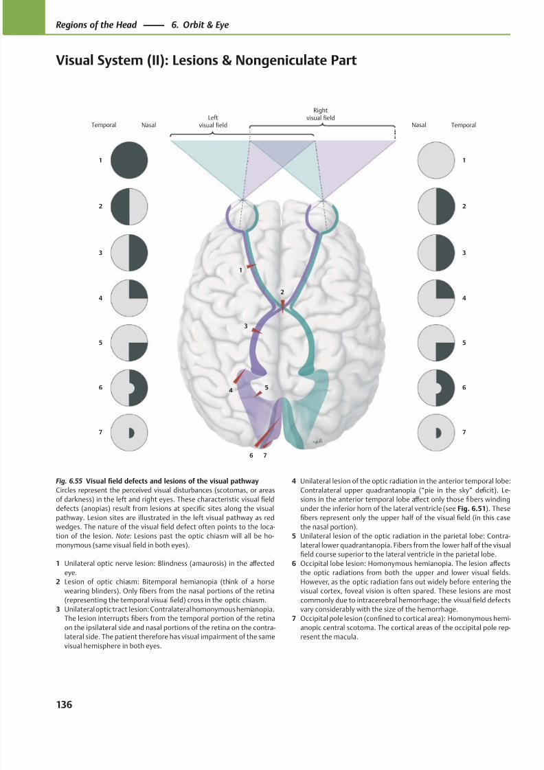
8/15/2019 Head and Neck Anatomy for Dental Medicine - Thieme; (January 26, 2010)
http://slidepdf.com/reader/full/head-and-neck-anatomy-for-dental-medicine-thieme-january-26-2010 149/384
7
6
5
4
3
2
1
Rightvisual fieldLeft
visual field
76
54
3
2
1
7
6
5
4
3
2
1
Temporal Nasal Nasal Temporal
Fig. 6.55 Visual field defects and lesions of the visual pathway
Circles represent the perceived visual disturbances (scotomas, or areas
of darkness) in the left and right eyes. These characteristic visual field
defects (anopias) result from lesions at specific sites along the visual
pathway. Lesion sites are illustrated in the left visual pathway as red
wedges. The nature of the visual field defect often points to the loca-
tion of the lesion. Note: Lesions past the optic chiasm will all be ho-monymous (same visual field in both eyes).
1 Unilateral optic nerve lesion: Blindness (amaurosis) in the aff ected
eye.
2 Lesion of optic chiasm: Bitemporal hemianopia (think of a horse
wearing blinders). Only fibers from the nasal portions of the retina
(representing the temporal visual field) cross in the optic chiasm.
3 Unilateral optic tract lesion: Contralateral homonymous hemianopia.
The lesion interrupts fibers from the temporal portion of the retina
on the ipsilateral side and nasal portions of the retina on the contra-
lateral side. The patient therefore has visual impairment of the same
visual hemisphere in both eyes.
4 Unilateral lesion of the optic radiation in the anterior temporal lobe:
Contralateral upper quadrantanopia (“pie in the sky” deficit). Le-
sions in the anterior temporal lobe aff ect only those fibers winding
under the inferior horn of the lateral ventricle (see Fig. 6.51). These
fibers represent only the upper half of the visual field (in this case
the nasal portion).
5 Unilateral lesion of the optic radiation in the parietal lobe: Contra-lateral lower quadrantanopia. Fibers from the lower half of the visual
field course superior to the lateral ventricle in the parietal lobe.
6 Occipital lobe lesion: Homonymous hemianopia. The lesion aff ects
the optic radiations from both the upper and lower visual fields.
However, as the optic radiation fans out widely before entering the
visual cortex, foveal vision is often spared. These lesions are most
commonly due to intracerebral hemorrhage; the visual field defects
vary considerably with the size of the hemorrhage.
7 Occipital pole lesion (confined to cortical area): Homonymous hemi-
anopic central scotoma. The cortical areas of the occipital pole rep-
resent the macula.
136
Regions of the Head 6. Orbit & Eye
Visual System (II): Lesions & Nongeniculate Part
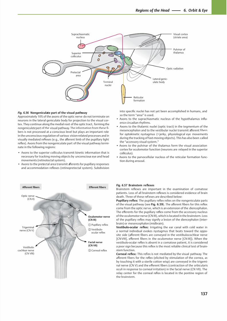
8/15/2019 Head and Neck Anatomy for Dental Medicine - Thieme; (January 26, 2010)
http://slidepdf.com/reader/full/head-and-neck-anatomy-for-dental-medicine-thieme-january-26-2010 150/384
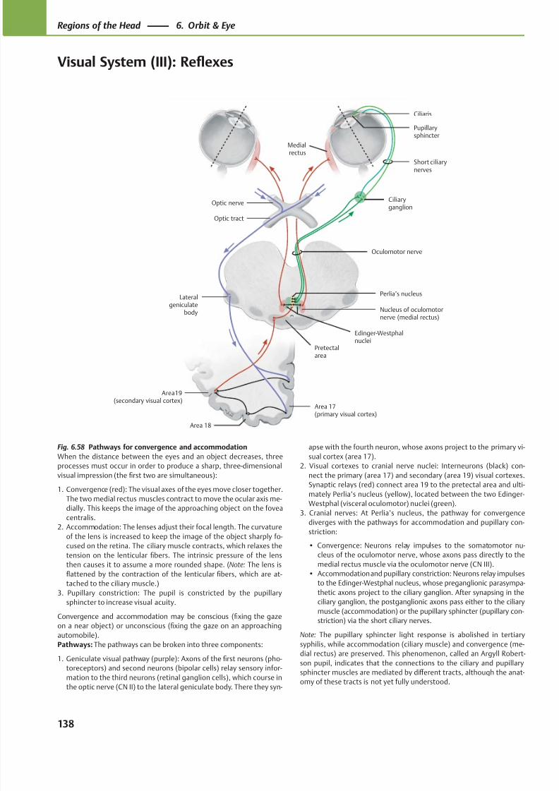
8/15/2019 Head and Neck Anatomy for Dental Medicine - Thieme; (January 26, 2010)
http://slidepdf.com/reader/full/head-and-neck-anatomy-for-dental-medicine-thieme-january-26-2010 151/384
Area19(secondary visual cortex)
Area 18
Area 17
(primary visual cortex)
Pretectalarea
Nucleus of oculomotornerve (medial rectus)
Perlia’s nucleus
Edinger-Westphalnuclei
Oculomotor nerve
Ciliaryganglion
Short ciliarynerves
Ciliaris
Pupillary
sphincter
Optic nerve
Optic tract
Lateralgeniculate
body
Medialrectus
Fig. 6.58 Pathways for convergence and accommodation
When the distance between the eyes and an object decreases, three
processes must occur in order to produce a sharp, three-dimensional
visual impression (the first two are simultaneous):
1. Convergence (red): The visual axes of the eyes move closer together.
The two medial rectus muscles contract to move the ocular axis me-
dially. This keeps the image of the approaching object on the fovea
centralis.
2. Accommodation: The lenses adjust their focal length. The curvature
of the lens is increased to keep the image of the object sharply fo-
cused on the retina. The ciliary muscle contracts, which relaxes the
tension on the lenticular fibers. The intrinsic pressure of the lensthen causes it to assume a more rounded shape. (Note: The lens is
flattened by the contraction of the lenticular fibers, which are at-
tached to the ciliary muscle.)
3. Pupillary constriction: The pupil is constricted by the pupillary
sphincter to increase visual acuity.
Convergence and accommodation may be conscious (fixing the gaze
on a near object) or unconscious (fixing the gaze on an approaching
automobile).
Pathways: The pathways can be broken into three components:
1. Geniculate visual pathway (purple): Axons of the first neurons (pho-
toreceptors) and second neurons (bipolar cells) relay sensory infor-
mation to the third neurons (retinal ganglion cells), which course in
the optic nerve (CN II) to the lateral geniculate body. There they syn-
apse with the fourth neuron, whose axons project to the primary vi-
sual cortex (area 17).
2. Visual cortexes to cranial nerve nuclei: Interneurons (black) con-
nect the primary (area 17) and secondary (area 19) visual cortexes.
Synaptic relays (red) connect area 19 to the pretectal area and ulti-
mately Perlia’s nucleus (yellow), located between the two Edinger-
Westphal (visceral oculomotor) nuclei (green).
3. Cranial nerves: At Perlia’s nucleus, the pathway for convergence
diverges with the pathways for accommodation and pupillary con-
striction:
• Convergence: Neurons relay impulses to the somatomotor nu-
cleus of the oculomotor nerve, whose axons pass directly to themedial rectus muscle via the oculomotor nerve (CN III).
• Accommodation and pupillary constriction: Neurons relay impulses
to the Edinger-Westphal nucleus, whose preganglionic parasympa-
thetic axons project to the ciliary ganglion. After synapsing in the
ciliary ganglion, the postganglionic axons pass either to the ciliary
muscle (accommodation) or the pupillary sphincter (pupillary con-
striction) via the short ciliary nerves.
Note: The pupillary sphincter light response is abolished in tertiary
syphilis, while accommodation (ciliary muscle) and convergence (me-
dial rectus) are preserved. This phenomenon, called an Argyll Robert-
son pupil, indicates that the connections to the ciliary and pupillary
sphincter muscles are mediated by diff erent tracts, although the anat-
omy of these tracts is not yet fully understood.
138
Regions of the Head 6. Orbit & Eye
Visual System (III): Reflexes
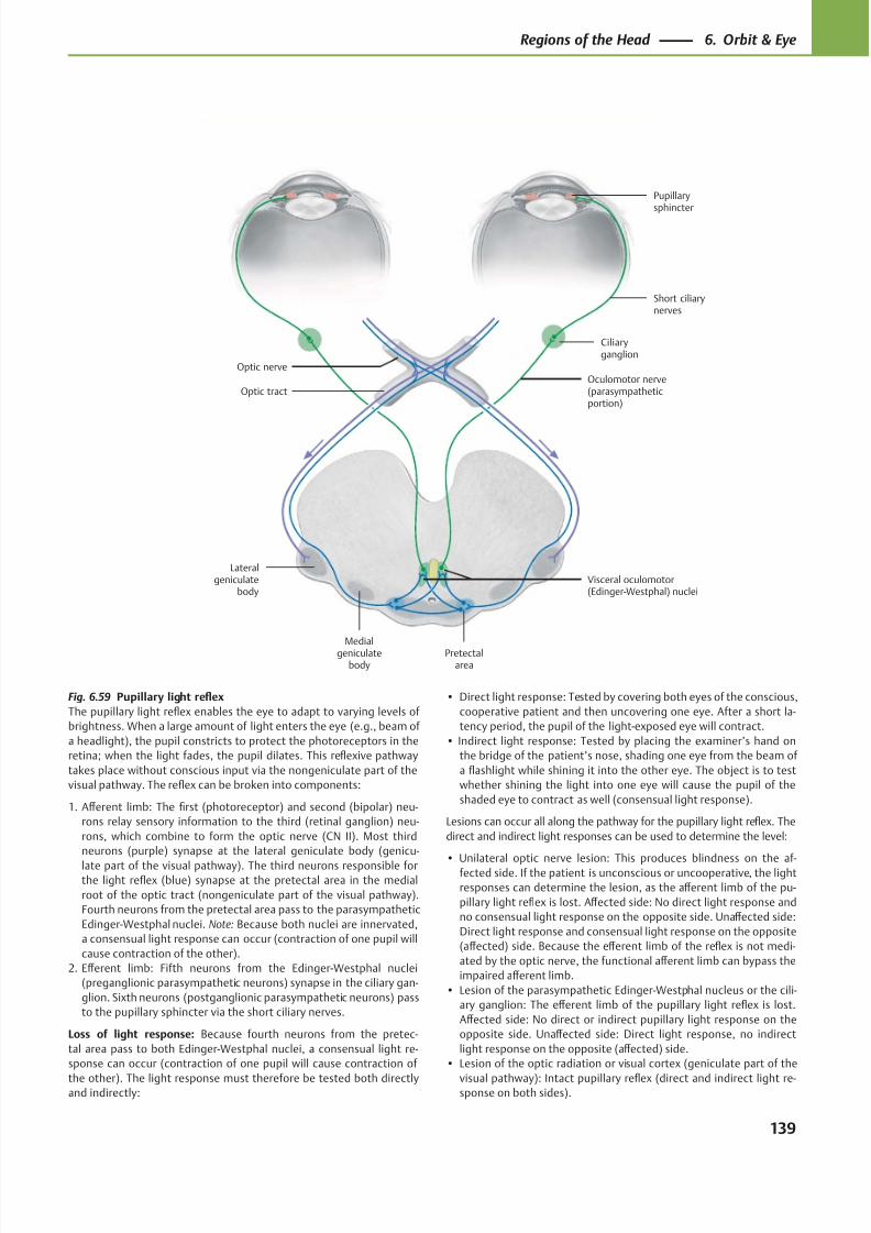
8/15/2019 Head and Neck Anatomy for Dental Medicine - Thieme; (January 26, 2010)
http://slidepdf.com/reader/full/head-and-neck-anatomy-for-dental-medicine-thieme-january-26-2010 152/384
Ciliaryganglion
Optic tract
Lateralgeniculate
body
Medialgeniculate
bodyPretectal
area
Visceral oculomotor(Edinger-Westphal) nuclei
Oculomotor nerve(parasympatheticportion)
Short ciliarynerves
Optic nerve
Pupillarysphincter
Fig. 6.59 Pupillary light reflex
The pupillary light reflex enables the eye to adapt to varying levels of
brightness. When a large amount of light enters the eye (e.g., beam of
a headlight), the pupil constricts to protect the photoreceptors in the
retina; when the light fades, the pupil dilates. This reflexive pathway
takes place without conscious input via the nongeniculate part of the
visual pathway. The reflex can be broken into components:
1. Aff erent limb: The first (photoreceptor) and second (bipolar) neu-
rons relay sensory information to the third (retinal ganglion) neu-
rons, which combine to form the optic nerve (CN II). Most third
neurons (purple) synapse at the lateral geniculate body (genicu-
late part of the visual pathway). The third neurons responsible forthe light reflex (blue) synapse at the pretectal area in the medial
root of the optic tract (nongeniculate part of the visual pathway).
Fourth neurons from the pretectal area pass to the parasympathetic
Edinger-Westphal nuclei. Note: Because both nuclei are innervated,
a consensual light response can occur (contraction of one pupil will
cause contraction of the other).
2. Eff erent limb: Fifth neurons from the Edinger-Westphal nuclei
(preganglionic parasympathetic neurons) synapse in the ciliary gan-
glion. Sixth neurons (postganglionic parasympathetic neurons) pass
to the pupillary sphincter via the short ciliary nerves.
Loss of light response: Because fourth neurons from the pretec-
tal area pass to both Edinger-Westphal nuclei, a consensual light re-
sponse can occur (contraction of one pupil will cause contraction of
the other). The light response must therefore be tested both directlyand indirectly:
• Direct light response: Tested by covering both eyes of the conscious,
cooperative patient and then uncovering one eye. After a short la-
tency period, the pupil of the light-exposed eye will contract.
• Indirect light response: Tested by placing the examiner’s hand on
the bridge of the patient’s nose, shading one eye from the beam of
a flashlight while shining it into the other eye. The object is to test
whether shining the light into one eye will cause the pupil of the
shaded eye to contract as well (consensual light response).
Lesions can occur all along the pathway for the pupillary light reflex. The
direct and indirect light responses can be used to determine the level:
• Unilateral optic nerve lesion: This produces blindness on the af-fected side. If the patient is unconscious or uncooperative, the light
responses can determine the lesion, as the aff erent limb of the pu-
pillary light reflex is lost. Aff ected side: No direct light response and
no consensual light response on the opposite side. Unaff ected side:
Direct light response and consensual light response on the opposite
(aff ected) side. Because the eff erent limb of the reflex is not medi-
ated by the optic nerve, the functional aff erent limb can bypass the
impaired aff erent limb.
• Lesion of the parasympathetic Edinger-Westphal nucleus or the cili-
ary ganglion: The eff erent limb of the pupillary light reflex is lost.
Aff ected side: No direct or indirect pupillary light response on the
opposite side. Unaff ected side: Direct light response, no indirect
light response on the opposite (aff ected) side.
• Lesion of the optic radiation or visual cortex (geniculate part of the
visual pathway): Intact pupillary reflex (direct and indirect light re-sponse on both sides).
139
Regions of the Head 6. Orbit & Eye
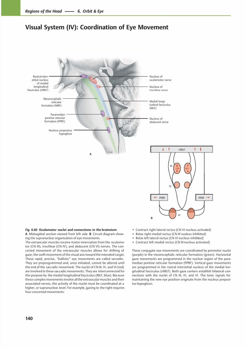
8/15/2019 Head and Neck Anatomy for Dental Medicine - Thieme; (January 26, 2010)
http://slidepdf.com/reader/full/head-and-neck-anatomy-for-dental-medicine-thieme-january-26-2010 153/384
Mesencephalicreticular
formation (MRF)
Paramedianpontine reticular
formation (PPRF)
Nucleus prepositushypoglossi
Nucleus of
abducent nerve
Nucleus of trochlear nerve
Nucleus of oculomotor nerve
Rostral inter-stitial nucleus
of mediallongitudinal
fasciculus (riMLF)
A
Medial longi-tudinal fasciculus(MLF)
PPRFPPRF
riMLF
III
IV
VIB
Fig. 6.60 Oculomotor nuclei and connections in the brainstem
A Midsagittal section viewed from left side. B Circuit diagram show-
ing the supranuclear organization of eye movements.
The extraocular muscles receive motor innervation from the oculomo-tor (CN III), trochlear (CN IV), and abducent (CN VI) nerves. The con-
certed movement of the extraocular muscles allows for shifting of
gaze, the swift movement of the visual axis toward the intended target.
These rapid, precise, “ballistic” eye movements are called saccades.
They are preprogrammed and, once initiated, cannot be altered until
the end of the saccadic movement. The nuclei of CN III, IV, and VI (red)
are involved in these saccadic movements. They are interconnected for
this purpose by the medial longitudinal fasciculus (MLF, blue). Because
these complex movements involve all the extraocular muscles and their
associated nerves, the activity of the nuclei must be coordinated at a
higher, or supranuclear, level. For example, gazing to the right requires
four concerted movements:
• Contract right lateral rectus (CN VI nucleus activated)
• Relax right medial rectus (CN III nucleus inhibited)
• Relax left lateral rectus (CN VI nucleus inhibited)
• Contract left medial rectus (CN III nucleus activated)
These conjugate eye movements are coordinated by premotor nuclei
(purple) in the mesencephalic reticular formation (green). Horizontal
gaze movements are programmed in the nuclear region of the para-
median pontine reticular formation (PPRF). Vertical gaze movements
are programmed in the rostral interstitial nucleus of the medial lon-
gitudinal fasciculus (riMLF). Both gaze centers establish bilateral con-
nections with the nuclei of CN III, IV, and VI. The tonic signals for
maintaining the new eye position originate from the nucleus preposi-
tus hypoglossi.
140
Regions of the Head 6. Orbit & Eye
Visual System (IV): Coordination of Eye Movement
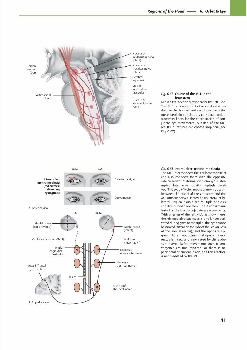
8/15/2019 Head and Neck Anatomy for Dental Medicine - Thieme; (January 26, 2010)
http://slidepdf.com/reader/full/head-and-neck-anatomy-for-dental-medicine-thieme-january-26-2010 154/384
Cortico-nuclear
fibers
Nucleus of abducent nerve(CN VI)
Mediallongitudinalfasciculus
Nucleus of trochlear nerve(CN IV)
Nucleus of oculomotor nerve
(CN III)
Corticospinaltract
Cerebralaqueduct
RightLeft
Oculomotor nerve (CN III)
Medial rectus(not activated)
Area 8 (frontalgaze center)
Abducentnerve (CN VI)
Lesion
Nucleus of abducent nerve
Nucleus of trochlear nerve
Nucleus of oculomotor nerve
Mediallongitudinal
fasciculus
Lateral rectus(intact)
Convergence
Gaze to the rightInternuclear
ophthalmoplegia(red arrows:abducting
nystagmus)
A
B
LeftRight
Anterior view.
Superior view.
Fig. 6.61 Course of the MLF in the
brainstem
Midsagittal section viewed from the left side.
The MLF runs anterior to the cerebral aque-
duct on both sides and continues from the
mesencephalon to the cervical spinal cord. It
transmits fibers for the coordination of con-
jugate eye movements. A lesion of the MLFresults in internuclear ophthalmoplegia (see
Fig. 6.62).
Fig. 6.62 Internuclear ophthalmoplegia
The MLF interconnects the oculomotor nuclei
and also connects them with the opposite
side. When this “information highway” is inter-
rupted, internuclear ophthalmoplegia devel-
ops. This type of lesion most commonly occurs
between the nuclei of the abducent and the
oculomotor nerves. It may be unilateral or bi-
lateral. Typical causes are multiple sclerosis
and diminished blood flow. The lesion is mani-
fested by the loss of conjugate eye movements.
With a lesion of the left MLF, as shown here,
the left medial rectus muscle is no longer acti-
vated during gaze to the right. The eye cannot
be moved inward on the side of the lesion (loss
of the medial rectus), and the opposite eye
goes into an abducting nystagmus (lateral
rectus is intact and innervated by the abdu-
cent nerve). Refl
ex movements such as con-vergence are not impaired, as there is no
peripheral or nuclear lesion, and this reaction
is not mediated by the MLF.
141
Regions of the Head 6. Orbit & Eye
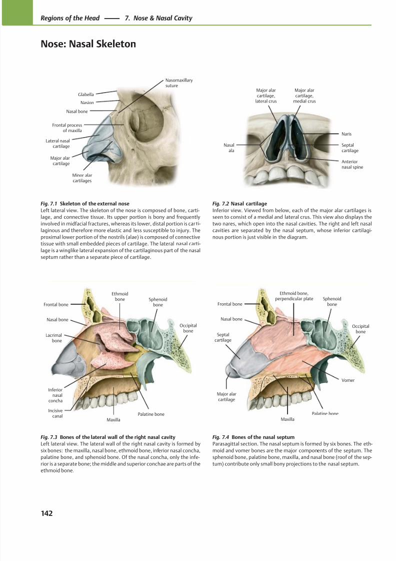
8/15/2019 Head and Neck Anatomy for Dental Medicine - Thieme; (January 26, 2010)
http://slidepdf.com/reader/full/head-and-neck-anatomy-for-dental-medicine-thieme-january-26-2010 155/384
Glabella
Frontal processof maxilla
Minor alarcartilages
Major alarcartilage
Lateral nasalcartilage
Nasal bone
Nasion
Nasomaxillarysuture
Naris
Anteriornasal spine
Major alar
cartilage,medial crus
Major alar
cartilage,lateral crus
Nasalala
Septalcartilage
Major alarcartilage
Septalcartilage
Vomer
Maxilla
Palatine bone
Frontal bone
Nasal bone
Sphenoidbone
Ethmoid bone,perpendicular plate
Occipitalbone
Lacrimalbone
MaxillaPalatine bone
Frontal bone
Nasal bone
Inferiornasal
concha
Sphenoidbone
Ethmoidbone
Occipitalbone
Incisivecanal
Fig. 7.1 Skeleton of the external nose
Left lateral view. The skeleton of the nose is composed of bone, carti-
lage, and connective tissue. Its upper portion is bony and frequently
involved in midfacial fractures, whereas its lower, distal portion is car ti-
laginous and therefore more elastic and less susceptible to injury. The
proximal lower portion of the nostrils (alae) is composed of connective
tissue with small embedded pieces of cartilage. The lateral nasal carti-
lage is a winglike lateral expansion of the cartilaginous part of the nasal
septum rather than a separate piece of cartilage.
Fig. 7.2 Nasal cartilage
Inferior view. Viewed from below, each of the major alar cartilages is
seen to consist of a medial and lateral crus. This view also displays the
two nares, which open into the nasal cavities. The right and left nasal
cavities are separated by the nasal septum, whose inferior cartilagi-
nous portion is just visible in the diagram.
Fig. 7.4 Bones of the nasal septum
Parasagittal section. The nasal septum is formed by six bones. The eth-
moid and vomer bones are the major components of the septum. The
sphenoid bone, palatine bone, maxilla, and nasal bone (roof of the sep-
tum) contribute only small bony projections to the nasal septum.
Fig. 7.3 Bones of the lateral wall of the right nasal cavity
Left lateral view. The lateral wall of the right nasal cavity is formed by
six bones: the maxilla, nasal bone, ethmoid bone, inferior nasal concha,
palatine bone, and sphenoid bone. Of the nasal concha, only the infe-
rior is a separate bone; the middle and superior conchae are parts of the
ethmoid bone.
142
Regions of the Head 7. Nose & Nasal Cavity
Nose: Nasal Skeleton
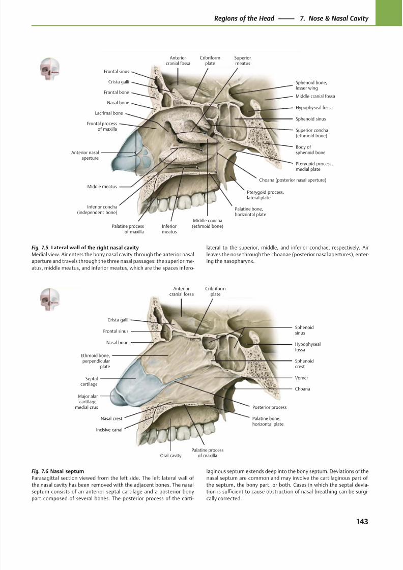
8/15/2019 Head and Neck Anatomy for Dental Medicine - Thieme; (January 26, 2010)
http://slidepdf.com/reader/full/head-and-neck-anatomy-for-dental-medicine-thieme-january-26-2010 156/384
Nasal bone
Frontal bone
Frontal sinus
Crista galli
Anteriorcranial fossa
Cribriformplate
Palatine processof maxilla
Inferior concha(independent bone)
Lacrimal bone
Frontal processof maxilla
Middle concha(ethmoid bone)
Pterygoid process,
lateral plate
Palatine bone,horizontal plate
Sphenoid bone,lesser wing
Hypophyseal fossa
Middle cranial fossa
Body ofsphenoid bone
Sphenoid sinus
Pterygoid process,medial plate
Superior concha(ethmoid bone)
Anterior nasalaperture
Superiormeatus
Middle meatus
Inferiormeatus
Choana (posterior nasal aperture)
Anteriorcranial fossa
Oral cavity
Hypophysealfossa
Major alarcartilage,
medial crus Posterior process
Palatine bone,horizontal plate
Vomer
Sphenoidcrest
Sphenoidsinus
Cribriformplate
Ethmoid bone,perpendicular
plate
Crista galli
Frontal sinus
Nasal bone
Septalcartilage
Palatine processof maxilla
Choana
Nasal crest
Incisive canal
Fig. 7.5 Lateral wall of the right nasal cavity
Medial view. Air enters the bony nasal cavity through the anterior nasal
aperture and travels through the three nasal passages: the superior me-
atus, middle meatus, and inferior meatus, which are the spaces infero-
lateral to the superior, middle, and inferior conchae, respectively. Air
leaves the nose through the choanae (posterior nasal apertures), enter-
ing the nasopharynx.
Fig. 7.6 Nasal septum
Parasagittal section viewed from the left side. The left lateral wall of
the nasal cavity has been removed with the adjacent bones. The nasal
septum consists of an anterior septal cartilage and a posterior bony
part composed of several bones. The posterior process of the carti-
laginous septum extends deep into the bony septum. Deviations of the
nasal septum are common and may involve the cartilaginous part of
the septum, the bony part, or both. Cases in which the septal devia-
tion is suffi cient to cause obstruction of nasal breathing can be surgi-
cally corrected.
143
Regions of the Head 7. Nose & Nasal Cavity
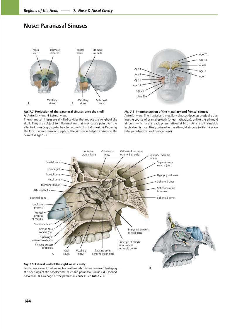
8/15/2019 Head and Neck Anatomy for Dental Medicine - Thieme; (January 26, 2010)
http://slidepdf.com/reader/full/head-and-neck-anatomy-for-dental-medicine-thieme-january-26-2010 157/384
Nasal bone
Frontal bone
Frontal sinus
Crista galli
Anteriorcranial fossa
Cribriformplate
Hypophyseal fossa
Sphenoid bone
Sphenoid sinus
Sphenopalatineforamen
Cut edge of middlenasal concha(ethmoid bone)
Palatine processof maxilla
Inferior nasalconcha (cut)
Palatine bone,perpendicular plate
Superior nasalconcha (cut)
Lacrimal bone
Frontalprocess
of maxilla
Oralcavity
Pterygoid process,medial plate
Ethmoid bulla
Orifices of posteriorethmoid air cells
Uncinateprocess
MaxillaryhiatusA
Frontonasal duct
Semilunar hiatus
Opening of nasolacrimal canal
Sphenoethmoidalrecess
Maxillarysinus
Ethmoidair cells
Frontalsinus
AMaxillary
sinusSphenoid
sinus
Ethmoidair cells
Frontalsinus
B
Age 60+
Age 20
Age 12
Age 8
Age 4
Age 1
Age 1
Age 4
Age 8
Age 12
Age 20
B
Fig. 7.7 Projection of the paranasal sinuses onto the skull
A Anterior view. B Lateral view.The paranasal sinuses are air-filled cavities that reduce the weight of the
skull. They are subject to inflammation that may cause pain over the
aff ected sinus (e.g., frontal headache due to frontal sinusitis). Knowing
the location and sensory supply of the sinuses is helpful in making the
correct diagnosis.
Fig. 7.8 Pneumatization of the maxillary and frontal sinuses
Anterior view. The frontal and maxillary sinuses develop gradually dur-ing the course of cranial growth (pneumatization), unlike the ethmoid
air cells, which are already pneumatized at birth. As a result, sinusitis
in children is most likely to involve the ethmoid air cells (with risk of or-
bital penetration: red, swollen eye).
Fig. 7.9 Lateral wall of the right nasal cavity
Left lateral view of midline section with nasal conchae removed to display
the openings of the nasolacrimal duct and paranasal sinuses. A Opened
nasal wall. B Drainage of the paranasal sinuses. See Table 7.1.
144
Regions of the Head 7. Nose & Nasal Cavity
Nose: Paranasal Sinuses
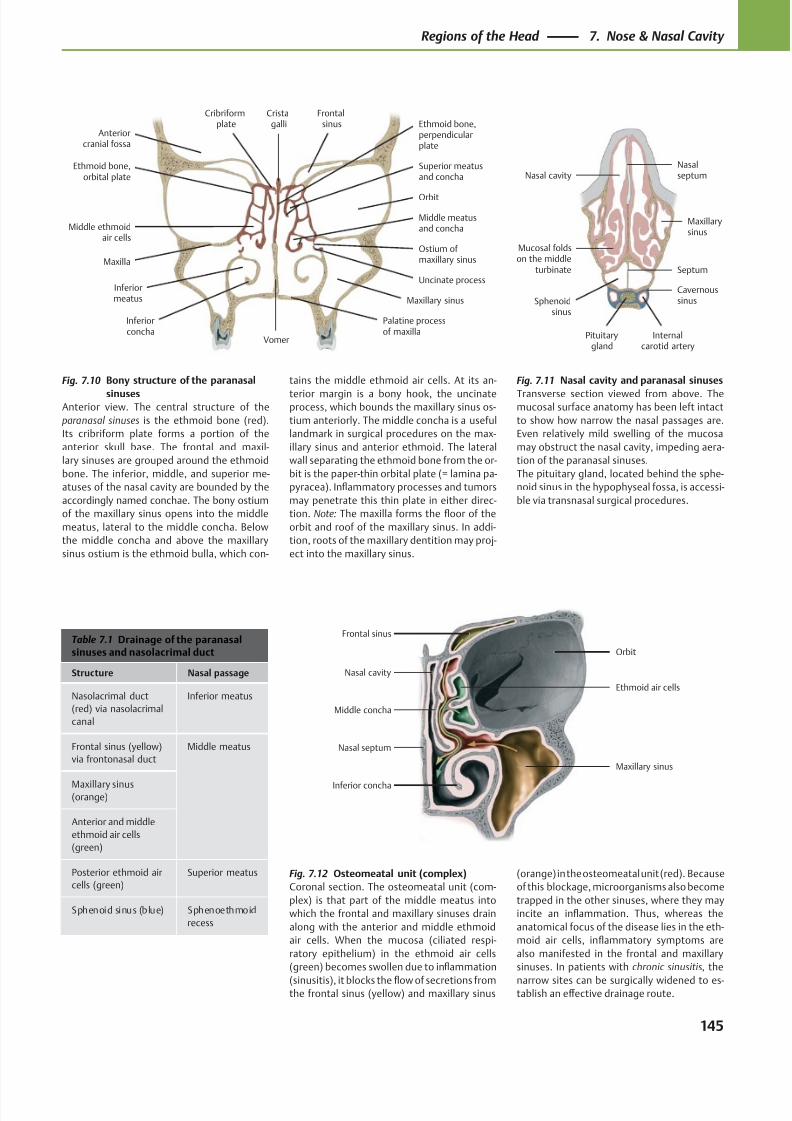
8/15/2019 Head and Neck Anatomy for Dental Medicine - Thieme; (January 26, 2010)
http://slidepdf.com/reader/full/head-and-neck-anatomy-for-dental-medicine-thieme-january-26-2010 158/384
Mucosal foldson the middle
turbinate
Pituitarygland
Internalcarotid artery
Cavernoussinus
Maxillarysinus
Nasalseptum
Sphenoidsinus
Nasal cavity
Septum
Nasal septum
Nasal cavity
Orbit
Maxillary sinus
Inferior concha
Middle concha
Ethmoid air cells
Frontal sinus
Cribriformplate
Palatine processof maxilla
Vomer
Ostium ofmaxillary sinus
Maxillary sinus
Uncinate process
Middle meatusand concha
Superior meatusand concha
Orbit
Frontalsinus
Cristagalli
Anteriorcranial fossa
Ethmoid bone,orbital plate
Maxilla
Inferiorconcha
Inferiormeatus
Middle ethmoidair cells
Ethmoid bone,perpendicularplate
Table 7.1 Drainage of the paranasalsinuses and nasolacrimal duct
Structure Nasal passage
Nasolacrimal duct
(red) via nasolacrimal
canal
Inferior meatus
Frontal sinus (yellow)
via frontonasal duct
Middle meatus
Maxillary sinus(orange)
Anterior and middle
ethmoid air cells
(green)
Posterior ethmoid air
cells (green)
Superior meatus
Sphenoid sinus (blue) Sphenoethmoid
recess
Fig. 7.11 Nasal cavity and paranasal sinuses
Transverse section viewed from above. Themucosal surface anatomy has been left intact
to show how narrow the nasal passages are.
Even relatively mild swelling of the mucosa
may obstruct the nasal cavity, impeding aera-
tion of the paranasal sinuses.
The pituitary gland, located behind the sphe-
noid sinus in the hypophyseal fossa, is accessi-
ble via transnasal surgical procedures.
Fig. 7.10 Bony structure of the paranasal
sinusesAnterior view. The central structure of the
paranasal sinuses is the ethmoid bone (red).
Its cribriform plate forms a portion of the
anterior skull base. The frontal and maxil-
lary sinuses are grouped around the ethmoid
bone. The inferior, middle, and superior me-
atuses of the nasal cavity are bounded by the
accordingly named conchae. The bony ostium
of the maxillary sinus opens into the middle
meatus, lateral to the middle concha. Below
the middle concha and above the maxillary
sinus ostium is the ethmoid bulla, which con-
tains the middle ethmoid air cells. At its an-
terior margin is a bony hook, the uncinateprocess, which bounds the maxillary sinus os-
tium anteriorly. The middle concha is a useful
landmark in surgical procedures on the max-
illary sinus and anterior ethmoid. The lateral
wall separating the ethmoid bone from the or-
bit is the paper-thin orbital plate (= lamina pa-
pyracea). Inflammatory processes and tumors
may penetrate this thin plate in either direc-
tion. Note: The maxilla forms the floor of the
orbit and roof of the maxillary sinus. In addi-
tion, roots of the maxillary dentition may proj-
ect into the maxillary sinus.
Fig. 7.12 Osteomeatal unit (complex)
Coronal section. The osteomeatal unit (com-
plex) is that part of the middle meatus into
which the frontal and maxillary sinuses drain
along with the anterior and middle ethmoid
air cells. When the mucosa (ciliated respi-
ratory epithelium) in the ethmoid air cells
(green) becomes swollen due to inflammation
(sinusitis), it blocks the flow of secretions fromthe frontal sinus (yellow) and maxillary sinus
(orange) in the osteomeatal unit (red). Because
of this blockage, microorganisms also become
trapped in the other sinuses, where they may
incite an inflammation. Thus, whereas the
anatomical focus of the disease lies in the eth-
moid air cells, inflammatory symptoms are
also manifested in the frontal and maxillary
sinuses. In patients with chronic sinusitis, the
narrow sites can be surgically widened to es-tablish an eff ective drainage route.
145
Regions of the Head 7. Nose & Nasal Cavity
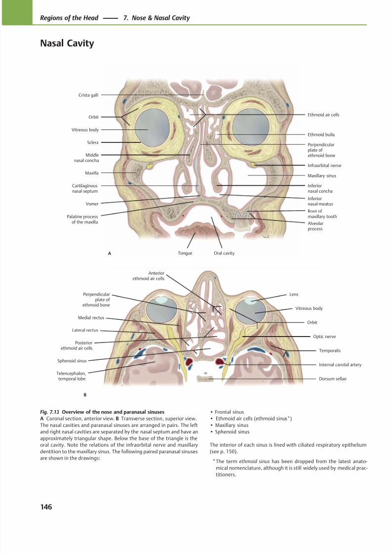
8/15/2019 Head and Neck Anatomy for Dental Medicine - Thieme; (January 26, 2010)
http://slidepdf.com/reader/full/head-and-neck-anatomy-for-dental-medicine-thieme-january-26-2010 159/384
Ethmoid air cellsOrbit
Vitreous body
Sclera
Maxilla
Cartilaginousnasal septum
Oral cavityTongue
VomerInferiornasal meatus
Inferiornasal concha
Middlenasal concha
Maxillary sinus
Infraorbital nerve
Ethmoid bulla
Perpendicularplate of ethmoid bone
Crista galli
Alveolarprocess
Palatine processof the maxilla
A
Root of maxillary tooth
Medial rectus
Lens
Vitreous body
Lateral rectus
Telencephalon,temporal lobe
Posteriorethmoid air cells
Dorsum sellae
Internal carotid artery
Optic nerve
Temporalis
Orbit
Perpendicularplate of
ethmoid bone
Sphenoid sinus
Anteriorethmoid air cells
B
Fig. 7.13 Overview of the nose and paranasal sinuses
A Coronal section, anterior view. B Transverse section, superior view.
The nasal cavities and paranasal sinuses are arranged in pairs. The left
and right nasal cavities are separated by the nasal septum and have an
approximately triangular shape. Below the base of the triangle is the
oral cavity. Note the relations of the infraorbital nerve and maxillary
dentition to the maxillary sinus. The following paired paranasal sinuses
are shown in the drawings:
• Frontal sinus
• Ethmoid air cells (ethmoid sinus*)
• Maxillary sinus
• Sphenoid sinus
The interior of each sinus is lined with ciliated respiratory epithelium
(see p. 150).
*The term ethmoid sinus has been dropped from the latest anato-
mical nomenclature, although it is still widely used by medical prac-
titioners.
146
Regions of the Head 7. Nose & Nasal Cavity
Nasal Cavity
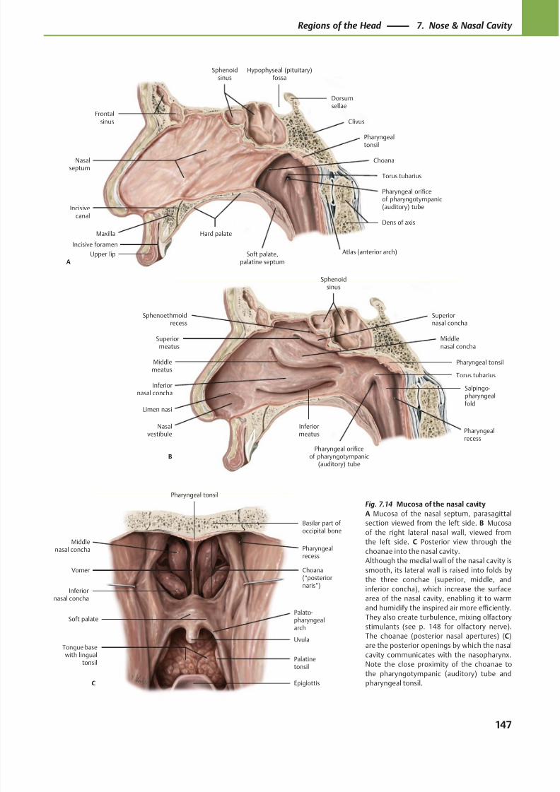
8/15/2019 Head and Neck Anatomy for Dental Medicine - Thieme; (January 26, 2010)
http://slidepdf.com/reader/full/head-and-neck-anatomy-for-dental-medicine-thieme-january-26-2010 160/384
Hypophyseal (pituitary)fossa
Sphenoidsinus
Frontalsinus
Nasalseptum
Maxilla
Upper lip
Hard palate
Choana
Soft palate,palatine septum
Pharyngeal orificeof pharyngotympanic(auditory) tube
Dens of axis
Torus tubarius
Clivus
Pharyngealtonsil
Dorsumsellae
A
Incisivecanal
Atlas (anterior arch)Incisive foramen
Limen nasi
Inferiormeatus
Nasalvestibule
Inferiornasal concha
Superiormeatus
Salpingo-pharyngealfold
Pharyngeal tonsil
Sphenoidsinus
Sphenoethmoidrecess
B
Middlemeatus
Superiornasal concha
Middlenasal concha
Torus tubarius
Pharyngeal orificeof pharyngotympanic
(auditory) tube
Pharyngealrecess
Middlenasal concha
Inferiornasal concha
Soft palate
Tongue basewith lingual
tonsil
Epiglottis
Uvula
Palato-pharyngealarch
Choana(“posteriornaris”)
Vomer
Pharyngeal tonsil
Basilar part of occipital bone
C
Palatinetonsil
Pharyngeal
recess
Fig. 7.14 Mucosa of the nasal cavity
A Mucosa of the nasal septum, parasagittal
section viewed from the left side. B Mucosa
of the right lateral nasal wall, viewed from
the left side. C Posterior view through the
choanae into the nasal cavity.Although the medial wall of the nasal cavity is
smooth, its lateral wall is raised into folds by
the three conchae (superior, middle, and
inferior concha), which increase the surface
area of the nasal cavity, enabling it to warm
and humidify the inspired air more effi ciently.
They also create turbulence, mixing olfactory
stimulants (see p. 148 for olfactory nerve).
The choanae (posterior nasal apertures) (C)
are the posterior openings by which the nasal
cavity communicates with the nasopharynx.
Note the close proximity of the choanae to
the pharyngotympanic (auditory) tube and
pharyngeal tonsil.
147
Regions of the Head 7. Nose & Nasal Cavity
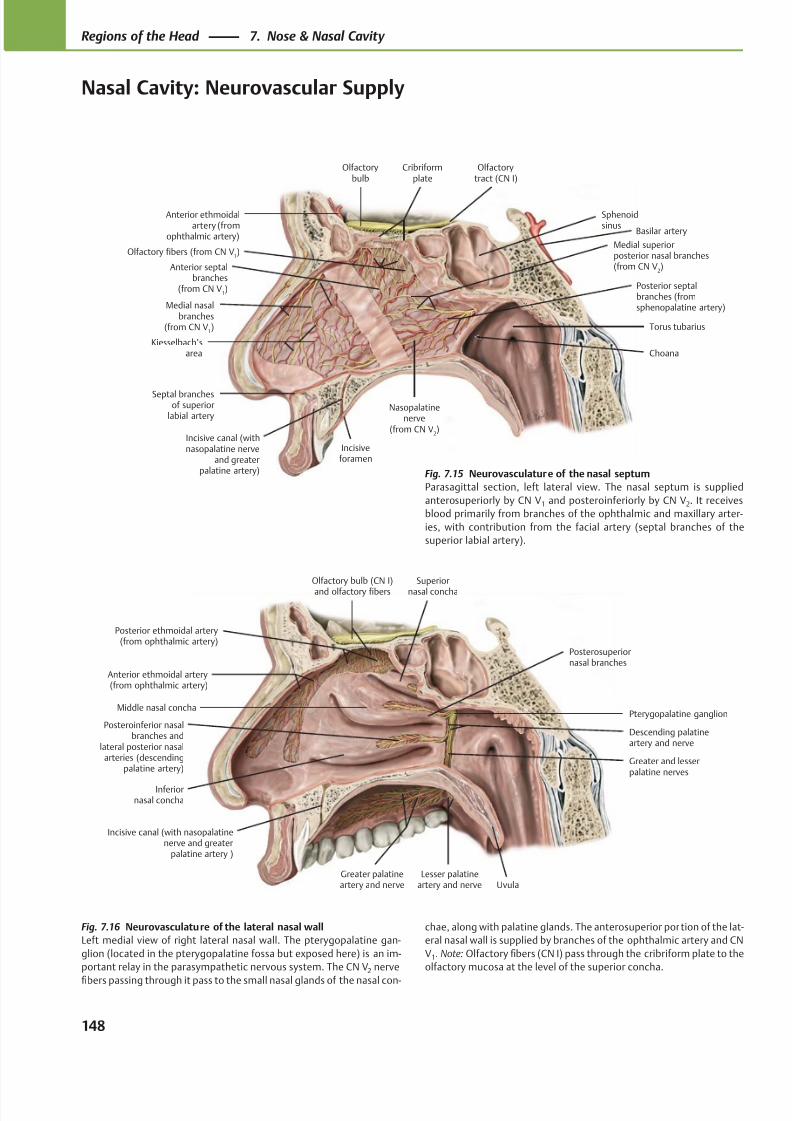
8/15/2019 Head and Neck Anatomy for Dental Medicine - Thieme; (January 26, 2010)
http://slidepdf.com/reader/full/head-and-neck-anatomy-for-dental-medicine-thieme-january-26-2010 161/384
Anterior ethmoidal artery(from ophthalmic artery)
Superior
nasal concha
Middle nasal concha
Inferiornasal concha
Posteroinferior nasalbranches and
lateral posterior nasalarteries (descending
palatine artery)
Greater palatineartery and nerve Uvula
Pterygopalatine ganglion
Posterior ethmoidal artery(from ophthalmic artery)
Olfactory bulb (CN I)
and olfactory fibers
Greater and lesserpalatine nerves
Incisive canal (with nasopalatinenerve and greater
palatine artery )
Lesser palatineartery and nerve
Descending palatineartery and nerve
Posterosuperiornasal branches
Anterior ethmoidalartery (from
ophthalmic artery)
Anterior septalbranches
(from CN V1)
Medial nasalbranches
(from CN V1)
Kiesselbach’sarea
Medial superiorposterior nasal branches(from CN V
2)
Nasopalatinenerve
(from CN V2)
Posterior septalbranches (fromsphenopalatine artery)
Choana
Torus tubarius
Sphenoidsinus
Olfactory fibers (from CN V1)
Cribriformplate
Olfactorybulb
Olfactorytract (CN I)
Septal branchesof superior
labial artery
Incisive canal (withnasopalatine nerve
and greaterpalatine artery)
Incisiveforamen
Basilar artery
Fig. 7.15 Neurovasculature of the nasal septum
Parasagittal section, left lateral view. The nasal septum is supplied
anterosuperiorly by CN V1 and posteroinferiorly by CN V2. It receives
blood primarily from branches of the ophthalmic and maxillary arter-
ies, with contribution from the facial artery (septal branches of the
superior labial artery).
Fig. 7.16 Neurovasculature of the lateral nasal wall
Left medial view of right lateral nasal wall. The pterygopalatine gan-
glion (located in the pterygopalatine fossa but exposed here) is an im-
portant relay in the parasympathetic nervous system. The CN V2 nerve
fibers passing through it pass to the small nasal glands of the nasal con-
chae, along with palatine glands. The anterosuperior portion of the lat-
eral nasal wall is supplied by branches of the ophthalmic artery and CN
V1. Note: Olfactory fibers (CN I) pass through the cribriform plate to the
olfactory mucosa at the level of the superior concha.
148
Regions of the Head 7. Nose & Nasal Cavity
Nasal Cavity: Neurovascular Supply
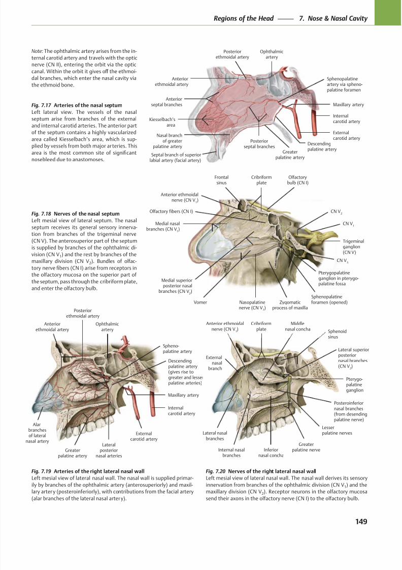
8/15/2019 Head and Neck Anatomy for Dental Medicine - Thieme; (January 26, 2010)
http://slidepdf.com/reader/full/head-and-neck-anatomy-for-dental-medicine-thieme-january-26-2010 162/384
Anteriorethmoidal artery
Anteriorseptal branches
Kiesselbach’sarea
Posteriorseptal branches
Sphenopalatineartery via spheno-palatine foramen
Maxillary artery
Externalcarotid artery
Internalcarotid artery
Ophthalmicartery
Posteriorethmoidal artery
Descendingpalatine artery
Greaterpalatine artery
Nasal branchof greater
palatine artery
Septal branch of superiorlabial artery (facial artery)
Anterior ethmoidal
nerve (CN V1)
Frontalsinus
Olfactory fibers (CN I)
Medial nasalbranches (CN V
1)
Medial superiorposterior nasal
branches (CN V2)
Vomer Nasopalatinenerve (CN V
2)
Zygomaticprocess of maxilla
Sphenopalatineforamen (opened)
Pterygopalatineganglion in pterygo-palatine fossa
CN V3
Trigeminalganglion(CN V)
CN V1
CN V2
Olfactorybulb (CN I)
Cribriformplate
Ophthalmicartery
Posteriorethmoidal artery
Anteriorethmoidal artery
Lateralposterior
nasal arteriesGreater
palatine artery
Descendingpalatine artery(gives rise togreater and lesserpalatine arteries)
Maxillary artery
Externalcarotid artery
Internalcarotid artery
Spheno-palatine artery
Alarbranchesof lateral
nasal artery
Cribriformplate
Anterior ethmoidalnerve (CN V
1)
Middlenasal concha
Externalnasal
branch
Lateral nasalbranches
Internal nasalbranches
Inferiornasal concha
Posteroinferiornasal branches(from desendingpalatine nerve)
Greaterpalatine nerve
Lesserpalatine nerves
Pterygo-palatineganglion
Lateral superiorposteriornasal branches(CN V
2)
Sphenoidsinus
Note: The ophthalmic artery arises from the in-
ternal carotid artery and travels with the optic
nerve (CN II), entering the orbit via the optic
canal. Within the orbit it gives off the ethmoi-
dal branches, which enter the nasal cavity via
the ethmoid bone.
Fig. 7.17 Arteries of the nasal septum
Left lateral view. The vessels of the nasal
septum arise from branches of the external
and internal carotid arteries. The anterior part
of the septum contains a highly vascularized
area called Kiesselbach’s area, which is sup-
plied by vessels from both major arteries. This
area is the most common site of significant
nosebleed due to anastomoses.
Fig. 7.18 Nerves of the nasal septum
Left mesial view of lateral septum. The nasal
septum receives its general sensory innerva-
tion from branches of the trigeminal nerve
(CN V). The anterosuperior part of the septum
is supplied by branches of the ophthalmic di-
vision (CN V1) and the rest by branches of the
maxillary division (CN V2). Bundles of olfac-
tory nerve fibers (CN I) arise from receptors in
the olfactory mucosa on the superior part of
the septum, pass through the cribriform plate,
and enter the olfactory bulb.
Fig. 7.19 Arteries of the right lateral nasal wall
Left mesial view of lateral nasal wall. The nasal wall is supplied primar-
ily by branches of the ophthalmic artery (anterosuperiorly) and maxil-
lary artery (posteroinferiorly), with contributions from the facial artery
(alar branches of the lateral nasal artery).
Fig. 7.20 Nerves of the right lateral nasal wall
Left mesial view of lateral nasal wall. The nasal wall derives its sensory
innervation from branches of the ophthalmic division (CN V1) and the
maxillary division (CN V2). Receptor neurons in the olfactory mucosa
send their axons in the olfactory nerve (CN I) to the olfactory bulb.
149
Regions of the Head 7. Nose & Nasal Cavity
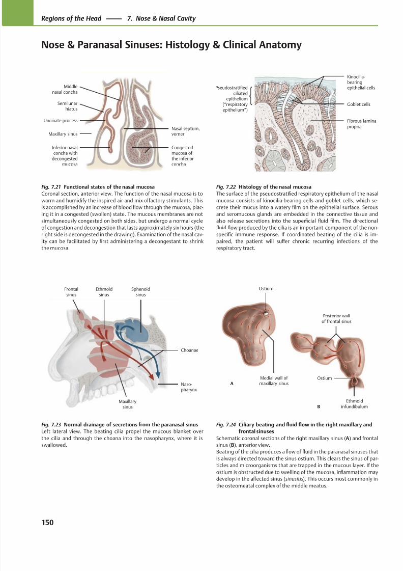
8/15/2019 Head and Neck Anatomy for Dental Medicine - Thieme; (January 26, 2010)
http://slidepdf.com/reader/full/head-and-neck-anatomy-for-dental-medicine-thieme-january-26-2010 163/384
Middlenasal concha
Semilunarhiatus
Uncinate process
Maxillary sinus
Inferior nasalconcha with
decongestedmucosa
Congestedmucosa of the inferiorconcha
Nasal septum,vomer
Pseudostratifiedciliated
epithelium(“respiratoryepithelium”)
Fibrous laminapropria
Goblet cells
Kinocilia-bearingepithelial cells
Maxillarysinus
Naso-pharynx
Choanae
Sphenoidsinus
Ethmoidsinus
Frontalsinus
Medial wall of maxillary sinus
Ostium
A
Ethmoidinfundibulum
Ostium
Posterior wallof frontal sinus
B
Fig. 7.21 Functional states of the nasal mucosa
Coronal section, anterior view. The function of the nasal mucosa is to
warm and humidify the inspired air and mix olfactory stimulants. Thisis accomplished by an increase of blood flow through the mucosa, plac-
ing it in a congested (swollen) state. The mucous membranes are not
simultaneously congested on both sides, but undergo a normal cycle
of congestion and decongestion that lasts approximately six hours (the
right side is decongested in the drawing). Examination of the nasal cav-
ity can be facilitated by first administering a decongestant to shrink
the mucosa.
Fig. 7.22 Histology of the nasal mucosa
The surface of the pseudostratified respiratory epithelium of the nasal
mucosa consists of kinocilia-bearing cells and goblet cells, which se-crete their mucus into a watery film on the epithelial surface. Serous
and seromucous glands are embedded in the connective tissue and
also release secretions into the superficial fluid film. The directional
fluid flow produced by the cilia is an important component of the non-
specific immune response. If coordinated beating of the cilia is im-
paired, the patient will suff er chronic recurring infections of the
respiratory tract.
Fig. 7.23 Normal drainage of secretions from the paranasal sinus
Left lateral view. The beating cilia propel the mucous blanket over
the cilia and through the choana into the nasopharynx, where it is
swallowed.
Fig. 7.24 Ciliary beating and fluid flow in the right maxillary and
frontal sinuses
Schematic coronal sections of the right maxillary sinus (A) and frontal
sinus (B), anterior view.
Beating of the cilia produces a flow of fluid in the paranasal sinuses that
is always directed toward the sinus ostium. This clears the sinus of par-
ticles and microorganisms that are trapped in the mucous layer. If the
ostium is obstructed due to swelling of the mucosa, inflammation may
develop in the aff ected sinus (sinusitis). This occurs most commonly in
the osteomeatal complex of the middle meatus.
150
Regions of the Head 7. Nose & Nasal Cavity
Nose & Paranasal Sinuses: Histology & Clinical Anatomy
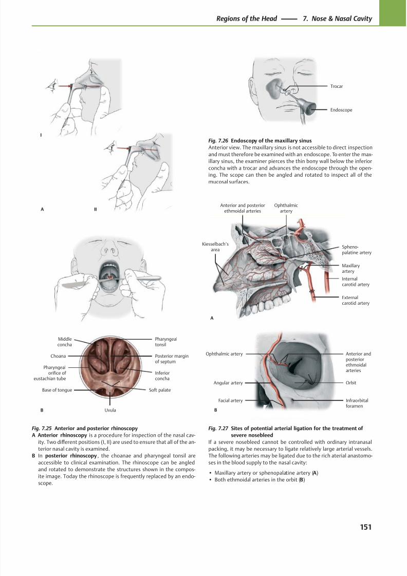
8/15/2019 Head and Neck Anatomy for Dental Medicine - Thieme; (January 26, 2010)
http://slidepdf.com/reader/full/head-and-neck-anatomy-for-dental-medicine-thieme-january-26-2010 164/384
Trocar
Endoscope
Anterior and posteriorethmoidal arteries
Kiesselbach’sarea
Maxillaryartery
External
carotid artery
Internalcarotid artery
Ophthalmicartery
Spheno-palatine artery
A
Facial artery Infraorbitalforamen
Orbit
Ophthalmic artery Anterior andposteriorethmoidalarteries
Angular artery
B
IIA
I
Choana
Pharyngealorifice of
eustachian tube
Soft palate
Uvula
Base of tongue
Posterior marginof septum
Inferiorconcha
Middleconcha
Pharyngealtonsil
B
Fig. 7.25 Anterior and posterior rhinoscopy
A Anterior rhinoscopy is a procedure for inspection of the nasal cav-
ity. Two diff erent positions (I, II) are used to ensure that all of the an-
terior nasal cavity is examined.
B In posterior rhinoscopy, the choanae and pharyngeal tonsil are
accessible to clinical examination. The rhinoscope can be angled
and rotated to demonstrate the structures shown in the compos-
ite image. Today the rhinoscope is frequently replaced by an endo-
scope.
Fig. 7.26 Endoscopy of the maxillary sinus
Anterior view. The maxillary sinus is not accessible to direct inspection
and must therefore be examined with an endoscope. To enter the max-
illary sinus, the examiner pierces the thin bony wall below the inferior
concha with a trocar and advances the endoscope through the open-
ing. The scope can then be angled and rotated to inspect all of the
mucosal surfaces.
Fig. 7.27 Sites of potential arterial ligation for the treatment of
severe nosebleed
If a severe nosebleed cannot be controlled with ordinary intranasal
packing, it may be necessary to ligate relatively large arterial vessels.
The following arteries may be ligated due to the rich aterial anastomo-
ses in the blood supply to the nasal cavity:
• Maxillary artery or sphenopalatine artery (A)
• Both ethmoidal arteries in the orbit (B)
151
Regions of the Head 7. Nose & Nasal Cavity
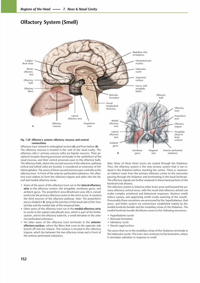
8/15/2019 Head and Neck Anatomy for Dental Medicine - Thieme; (January 26, 2010)
http://slidepdf.com/reader/full/head-and-neck-anatomy-for-dental-medicine-thieme-january-26-2010 165/384
Medialolfactory
stria
Olfactorybulb
Olfactoryfibers
Olfactorymucosa
Prepiriformarea
Lateralolfactory stria
Dorsallongitudinalfasciculus
Reticularformation
Tegmentalnucleus
Interpeduncularnucleus
Habenularnuclei
Longitu-dinal striae
A
Medullary striaof thalamus
Uncus, withamygdalabelow
Olfactorytrigone
Lateralolfactory
stria
Ambientgyrus
Semilunargyrus
Diagonalstria
Medialolfactory
stria
Olfactorytract
Olfactorybulb
Anterior perforatedsubstanceB
Prepiriformarea
Amygdala(deep tobrainsurface)Fig. 7.28 Olfactory system: olfactory mucosa and central
connections
Olfactory tract viewed in midsagittal section (A) and from below (B).
The olfactory mucosa is located in the roof of the nasal cavity. The
olfactory cells (= primary sensory cells) are bipolar neurons. Their pe-
ripheral receptor-bearing processes terminate in the epithelium of the
nasal mucosa, and their central processes pass to the olfactory bulb.
The olfactory bulb, where the second neurons of the olfactory pathway
(mitral and tufted cells) are located, is considered an extension of the
telencephalon. The axons of these second neurons pass centrally as the
olfactory tract. In front of the anterior perforated substance, the olfac-
tory tract widens to form the olfactory trigone and splits into the lat-
eral and medial olfactory striae.
• Some of the axons of the olfactory tract run in the lateral olfactory
stria to the olfactory centers: the amygdala, semilunar gyrus, and
ambient gyrus. The prepiriform area (Brodmann area 28) is consid-
ered to be the primary olfactory cortex in the strict sense. It contains
the third neurons of the olfactory pathway. Note: The prepiriformarea is shaded in B, lying at the junction of the basal side of the fron-
tal lobe and the medial side of the temporal lobe.
• Other axons of the olfactory tract run in the medial olfactory stria
to nuclei in the septal (subcallosal) area, which is part of the limbic
system, and to the olfactory tubercle, a small elevation in the ante-
rior perforated substance.
• Yet other axons of the olfactory tract terminate in the anterior
olfactory nucleus, where the fibers that cross to the opposite side
branch off and are relayed. This nucleus is located in the olfactory
trigone, which lies between the two olfactory striae and in front of
the anterior perforated substance.
Note: None of these three tracts are routed through the thalamus.
Thus, the olfactory system is the only sensory system that is not re-
layed in the thalamus before reaching the cortex. There is, however,
an indirect route from the primary olfactory cortex to the neocortex
passing through the thalamus and terminating in the basal forebrain.
The olfactory signals are further analyzed in these basal portions of the
forebrain (not shown).
The olfactory system is linked to other brain areas well beyond the pri-
mary olfactory cortical areas, with the result that olfactory stimuli can
evoke complex emotional and behavioral responses. Noxious smells
induce nausea, and appetizing smells evoke watering of the mouth.Presumably these sensations are processed by the hypothalamus, thal-
amus, and limbic system via connections established mainly by the
medial forebrain bundle and the medullary striae of the thalamus. The
medial forebrain bundle distributes axons to the following structures:
• Hypothalamic nuclei
• Reticular formation
• Salivatory nuclei
• Dorsal vagal nucleus
The axons that run in the medullary striae of the thalamus terminate in
the habenular nuclei. This tract also continues to the brainstem, where
it stimulates salivation in response to smell.
152
Regions of the Head 7. Nose & Nasal Cavity
Olfactory System (Smell)
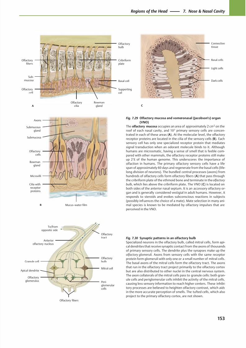
8/15/2019 Head and Neck Anatomy for Dental Medicine - Thieme; (January 26, 2010)
http://slidepdf.com/reader/full/head-and-neck-anatomy-for-dental-medicine-thieme-january-26-2010 166/384
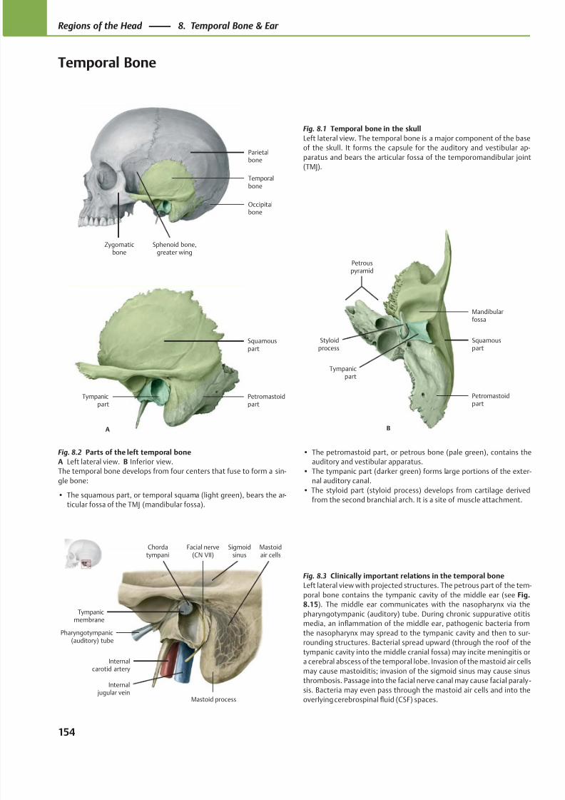
8/15/2019 Head and Neck Anatomy for Dental Medicine - Thieme; (January 26, 2010)
http://slidepdf.com/reader/full/head-and-neck-anatomy-for-dental-medicine-thieme-january-26-2010 167/384
Tympanicmembrane
Pharyngotympanic(auditory) tube
Internalcarotid artery
Internal jugular vein
Mastoidair cells
Chordatympani
Mastoid process
Facial nerve(CN VII)
Sigmoidsinus
Occipitalbone
Parietalbone
Sphenoid bone,greater wing
Zygomaticbone
Temporalbone
Tympanicpart
Petromastoidpart
Squamouspart
A
Mandibularfossa
Styloidprocess
Tympanicpart
Petromastoidpart
Squamouspart
B
Petrouspyramid
Fig. 8.1 Temporal bone in the skull
Left lateral view. The temporal bone is a major component of the baseof the skull. It forms the capsule for the auditory and vestibular ap-
paratus and bears the articular fossa of the temporomandibular joint
(TMJ).
Fig. 8.2 Parts of the left temporal bone
A Left lateral view. B Inferior view.
The temporal bone develops from four centers that fuse to form a sin-
gle bone:
• The squamous part, or temporal squama (light green), bears the ar-
ticular fossa of the TMJ (mandibular fossa).
• The petromastoid part, or petrous bone (pale green), contains the
auditory and vestibular apparatus.
• The tympanic part (darker green) forms large portions of the exter-
nal auditory canal.
• The styloid part (styloid process) develops from cartilage derived
from the second branchial arch. It is a site of muscle attachment.
Fig. 8.3 Clinically important relations in the temporal bone
Left lateral view with projected structures. The petrous part of the tem-
poral bone contains the tympanic cavity of the middle ear (see Fig.
8.15). The middle ear communicates with the nasopharynx via the
pharyngotympanic (auditory) tube. During chronic suppurative otitis
media, an inflammation of the middle ear, pathogenic bacteria from
the nasopharynx may spread to the tympanic cavity and then to sur-
rounding structures. Bacterial spread upward (through the roof of the
tympanic cavity into the middle cranial fossa) may incite meningitis or
a cerebral abscess of the temporal lobe. Invasion of the mastoid air cells
may cause mastoiditis; invasion of the sigmoid sinus may cause sinus
thrombosis. Passage into the facial nerve canal may cause facial paraly -
sis. Bacteria may even pass through the mastoid air cells and into the
overlying cerebrospinal fluid (CSF) spaces.
154
Regions of the Head 8. Temporal Bone & Ear
Temporal Bone
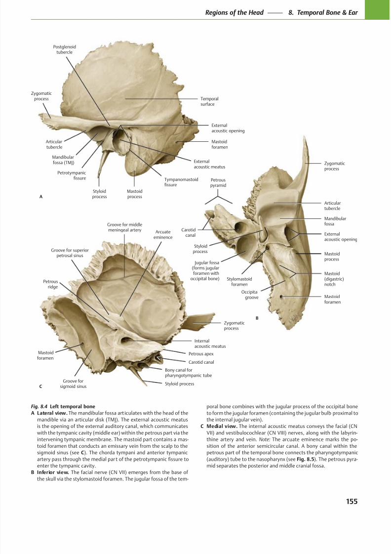
8/15/2019 Head and Neck Anatomy for Dental Medicine - Thieme; (January 26, 2010)
http://slidepdf.com/reader/full/head-and-neck-anatomy-for-dental-medicine-thieme-january-26-2010 168/384
Petrous apex
Groove for middlemeningeal artery
Internalacoustic meatus
Zygomaticprocess
Styloid processGroove for
sigmoid sinus
Mastoidforamen
C
Arcuateeminence
Groove for superiorpetrosal sinus
Petrousridge
Bony canal forpharyngotympanic tube
Carotid canal
Carotidcanal
Jugular fossa(forms jugularforamen with
occipital bone)
Mastoidforamen
Mastoid(digastric)notch
Mastoidprocess
Stylomastoidforamen
Externalacoustic opening
Styloidprocess
Mandibularfossa
Articulartubercle
Zygomaticprocess
B
Occipitalgroove
Petrouspyramid
Petrotympanicfissure
Styloidprocess
Externalacoustic meatus
Mastoidprocess
Mastoidforamen
Externalacoustic opening
Temporalsurface
Mandibularfossa (TMJ)
Zygomaticprocess
Articulartubercle
A
Tympanomastoidfissure
Postglenoidtubercle
Fig. 8.4 Left temporal bone
A Lateral view. The mandibular fossa art iculates with the head of the
mandible via an articular disk (TMJ). The external acoustic meatus
is the opening of the external auditory canal, which communicates
with the tympanic cavity (middle ear) within the petrous part via the
intervening tympanic membrane. The mastoid part contains a mas-
toid foramen that conducts an emissary vein from the scalp to the
sigmoid sinus (see C). The chorda tympani and anterior tympanic
enter the tympanic cavity.
B Inferior view. The facial nerve (CN VII) emerges from the base of
the skull via the stylomastoid foramen. The jugular fossa of the tem-
poral bone combines with the jugular process of the occipital bone
to form the jugular foramen (containing the jugular bulb proximal to
the internal jugular vein).
C Medial view. The internal acoustic meatus conveys the facial (CN
VII) and vestibulocochlear (CN VIII) nerves, along with the labyrin-
thine artery and vein. Note: The arcuate eminence marks the po-
sition of the anterior semicircular canal. A bony canal within the
petrous part of the temporal bone connects the pharyngotympanic
(auditory) tube to the nasopharynx (see Fig. 8.5). The petrous pyra-
mid separates the posterior and middle cranial fossa.
155
Regions of the Head 8. Temporal Bone & Ear
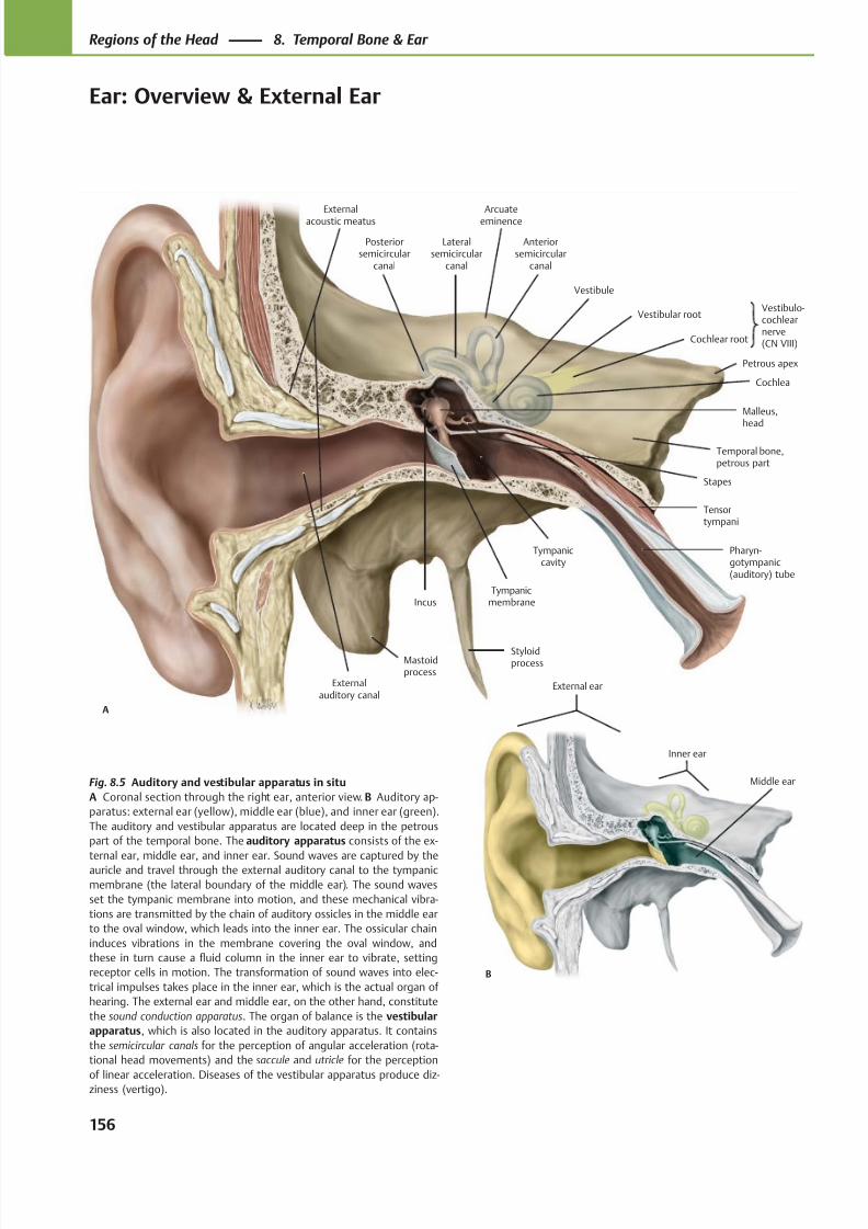
8/15/2019 Head and Neck Anatomy for Dental Medicine - Thieme; (January 26, 2010)
http://slidepdf.com/reader/full/head-and-neck-anatomy-for-dental-medicine-thieme-january-26-2010 169/384
Vestibule
Tympanicmembrane
Tympaniccavity
Pharyn-gotympanic(auditory) tube
Tensortympani
Stapes
Cochlea
Cochlear root
Vestibular root
Malleus,head
Temporal bone,petrous part
Anteriorsemicircular
canal
Lateralsemicircular
canal
Posteriorsemicircular
canal
Incus
A
Externalauditory canal
Styloidprocess
Vestibulo-cochlearnerve(CN VIII)
Petrous apex
Arcuateeminence
Externalacoustic meatus
Mastoidprocess
B
External ear
Inner ear
Middle earFig. 8.5 Auditory and vestibular apparatus in situ
A Coronal section through the right ear, anterior view. B Auditory ap-
paratus: external ear (yellow), middle ear (blue), and inner ear (green).
The auditory and vestibular apparatus are located deep in the petrous
part of the temporal bone. The auditory apparatus consists of the ex-
ternal ear, middle ear, and inner ear. Sound waves are captured by theauricle and travel through the external auditory canal to the tympanic
membrane (the lateral boundary of the middle ear). The sound waves
set the tympanic membrane into motion, and these mechanical vibra-
tions are transmitted by the chain of auditory ossicles in the middle ear
to the oval window, which leads into the inner ear. The ossicular chain
induces vibrations in the membrane covering the oval window, and
these in turn cause a fluid column in the inner ear to vibrate, setting
receptor cells in motion. The transformation of sound waves into elec-
trical impulses takes place in the inner ear, which is the actual organ of
hearing. The external ear and middle ear, on the other hand, constitute
the sound conduction apparatus. The organ of balance is the vestibular
apparatus, which is also located in the auditory apparatus. It contains
the semicircular canals for the perception of angular acceleration (rota-
tional head movements) and the saccule and utricle for the perception
of linear acceleration. Diseases of the vestibular apparatus produce diz-ziness (vertigo).
156
Regions of the Head 8. Temporal Bone & Ear
Ear: Overview & External Ear
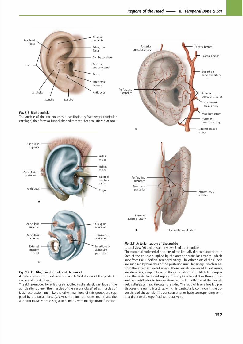
8/15/2019 Head and Neck Anatomy for Dental Medicine - Thieme; (January 26, 2010)
http://slidepdf.com/reader/full/head-and-neck-anatomy-for-dental-medicine-thieme-january-26-2010 170/384
Helix
Scaphoidfossa
Antihelix
Earlobe
Intertragicincisure
Tragus
Externalauditory canal
Concha
Cymba conchae
Triangularfossa
Crura of antihelix
Antitragus
A
Auricularissuperior
Auricularisposterior
AntitragusTragus
External
auditorycanal
Helicisminor
Helicismajor
Perforatingbranches
Superficialtemporal artery
Anteriorauricular arteries
A
Posteriorauricular artery
External carotidartery
Maxillary artery
Transversefacial artery
Frontal branch
Parietal branchPosteriorauricular artery
B
Auricularisposterior
Perforating
branches
Posteriorauricular artery
Anastomoticarcades
External carotid artery
B
Auricularissuperior
Auricularisanterior
Externalauditory
canal
Transversusauriculae
Insertions of auricularisposterior
Obliquusauriculae
Fig. 8.8 Arterial supply of the auricle
Lateral view (A) and posterior view (B) of right auricle.
The proximal and medial portions of the laterally directed anterior sur-
face of the ear are supplied by the anterior auricular arteries, which
arise from the superficial temporal artery. The other parts of the auricle
are supplied by branches of the posterior auricular artery, which arises
from the external carotid artery. These vessels are linked by extensive
anastomoses, so operations on the external ear are unlikely to compro-
mise the auricular blood supply. The copious blood flow through the
auricle contributes to temperature regulation: dilation of the vessels
helps dissipate heat through the skin. The lack of insulating fat pre-
disposes the ear to frostbite, which is particularly common in the up-
per third of the auricle. The auricular arteries have corresponding veins
that drain to the superficial temporal vein.
Fig. 8.7 Cartilage and muscles of the auricle
A Lateral view of the external surface. B Medial view of the posterior
surface of the right ear.
The skin (removed here) is closely applied to the elastic cartilage of the
auricle (light blue). The muscles of the ear are classified as muscles of
facial expression and, like the other members of this group, are sup-
plied by the facial nerve (CN VII). Prominent in other mammals, the
auricular muscles are vestigial in humans, with no significant function.
Fig. 8.6 Right auricle
The auricle of the ear encloses a cartilaginous framework (auricular
cartilage) that forms a funnel-shaped receptor for acoustic vibrations.
157
Regions of the Head 8. Temporal Bone & Ear
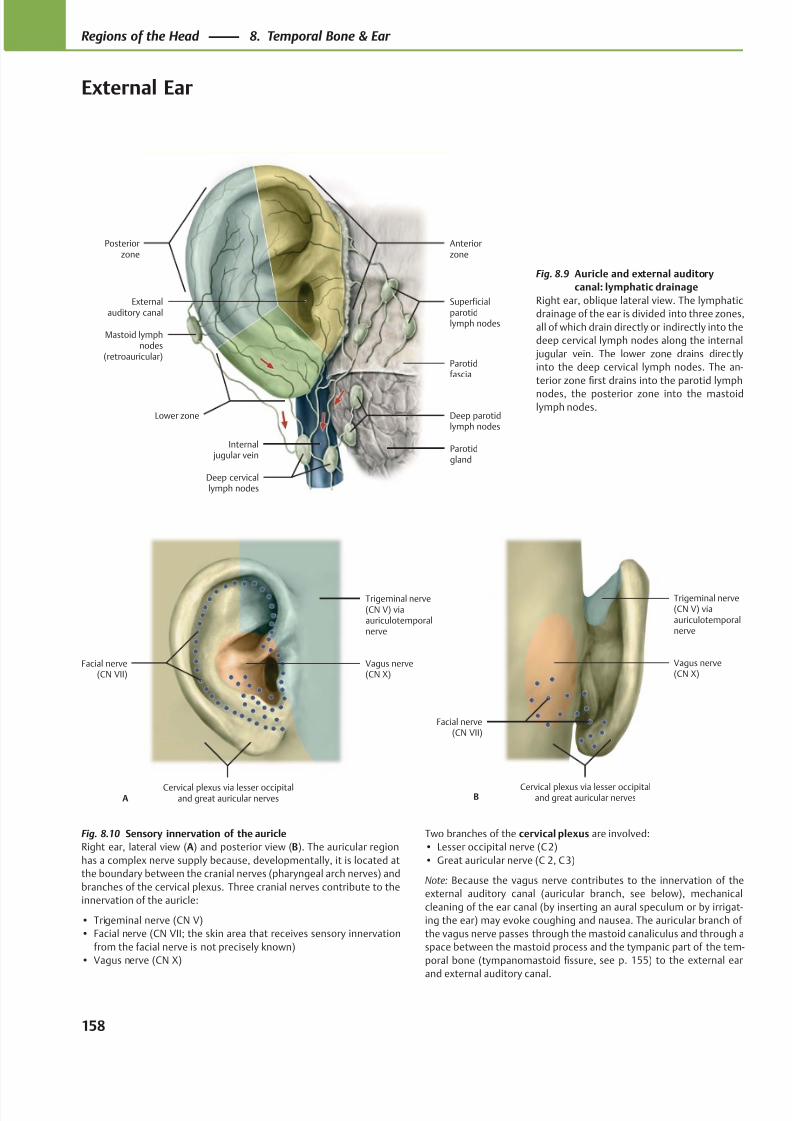
8/15/2019 Head and Neck Anatomy for Dental Medicine - Thieme; (January 26, 2010)
http://slidepdf.com/reader/full/head-and-neck-anatomy-for-dental-medicine-thieme-january-26-2010 171/384
Externalauditory canal
Posteriorzone
Anteriorzone
Lower zone
Mastoid lymphnodes
(retroauricular)
Deep cervicallymph nodes
Internal jugular vein
Parotidgland
Deep parotidlymph nodes
Parotidfascia
Superficialparotidlymph nodes
Facial nerve(CN VII)
Cervical plexus via lesser occipitaland great auricular nerves
Vagus nerve(CN X)
Trigeminal nerve(CN V) viaauriculotemporalnerve
A
Facial nerve(CN VII)
Cervical plexus via lesser occipitaland great auricular nerves
Vagus nerve(CN X)
Trigeminal nerve(CN V) viaauriculotemporalnerve
B
Fig. 8.9 Auricle and external auditory
canal: lymphatic drainage
Right ear, oblique lateral view. The lymphatic
drainage of the ear is divided into three zones,
all of which drain directly or indirectly into the
deep cervical lymph nodes along the internal
jugular vein. The lower zone drains directly
into the deep cervical lymph nodes. The an-
terior zone first drains into the parotid lymph
nodes, the posterior zone into the mastoidlymph nodes.
Fig. 8.10 Sensory innervation of the auricle
Right ear, lateral view (A) and posterior view (B). The auricular region
has a complex nerve supply because, developmentally, it is located at
the boundary between the cranial nerves (pharyngeal arch nerves) and
branches of the cervical plexus. Three cranial nerves contribute to the
innervation of the auricle:
• Trigeminal nerve (CN V)
• Facial nerve (CN VII; the skin area that receives sensory innervation
from the facial nerve is not precisely known)
• Vagus nerve (CN X)
Two branches of the cervical plexus are involved:
• Lesser occipital nerve (C 2)
• Great auricular nerve (C 2, C 3)
Note: Because the vagus nerve contributes to the innervation of the
external auditory canal (auricular branch, see below), mechanical
cleaning of the ear canal (by inserting an aural speculum or by irrigat-
ing the ear) may evoke coughing and nausea. The auricular branch of
the vagus nerve passes through the mastoid canaliculus and through a
space between the mastoid process and the tympanic part of the tem-
poral bone (tympanomastoid fissure, see p. 155) to the external ear
and external auditory canal.
158
Regions of the Head 8. Temporal Bone & Ear
External Ear
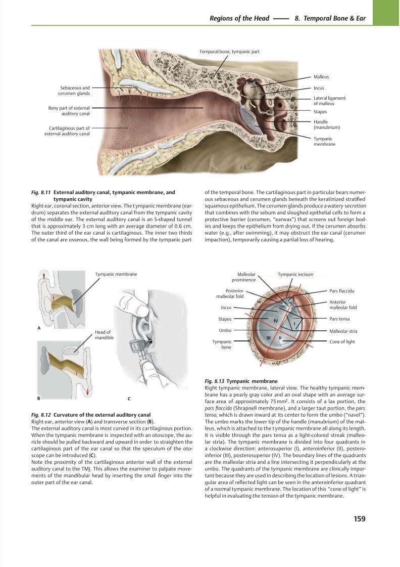
8/15/2019 Head and Neck Anatomy for Dental Medicine - Thieme; (January 26, 2010)
http://slidepdf.com/reader/full/head-and-neck-anatomy-for-dental-medicine-thieme-january-26-2010 172/384
Cartilaginous part of external auditory canal
Handle(manubrium)
Tympanicmembrane
Stapes
Incus
Malleus
Lateral ligamentof malleus
Sebaceous andcerumen glands
Bony part of externalauditory canal
Temporal bone, tympanic part
Malleolarprominence
Posterior
malleolar fold
Incus
Stapes
Tympanicbone
Cone of light
Umbo Malleolar stria
Pars tensa
Anteriormalleolar fold
Pars flaccida
Tympanic incisure
I
IIIII
IV
CB
Head of mandible
A
Tympanic membrane
Fig. 8.11 External auditory canal, tympanic membrane, and
tympanic cavityRight ear, coronal section, anterior view. The t ympanic membrane (ear-
drum) separates the external auditory canal from the tympanic cavity
of the middle ear. The external auditory canal is an S-shaped tunnel
that is approximately 3 cm long with an average diameter of 0.6 cm.
The outer third of the ear canal is cartilaginous. The inner two thirds
of the canal are osseous, the wall being formed by the tympanic part
Fig. 8.13 Tympanic membrane
Right tympanic membrane, lateral view. The healthy tympanic mem-
brane has a pearly gray color and an oval shape with an average sur-face area of approximately 75 mm2. It consists of a lax portion, the
pars flaccida (Shrapnell membrane), and a larger taut portion, the pars
tensa, which is drawn inward at its center to form the umbo (“navel”).
The umbo marks the lower tip of the handle (manubrium) of the mal-
leus, which is attached to the t ympanic membrane all along its length.
It is visible through the pars tensa as a light-colored streak (malleo-
lar stria). The tympanic membrane is divided into four quadrants in
a clockwise direction: anterosuperior (I), anteroinferior (II), postero-
inferior (III), posterosuperior (IV). The boundary lines of the quadrants
are the malleolar stria and a line intersecting it perpendicularly at the
umbo. The quadrants of the tympanic membrane are clinically impor-
tant because they are used in describing the location of lesions. A trian-
gular area of reflected light can be seen in the anteroinferior quadrant
of a normal tympanic membrane. The location of this “cone of light” is
helpful in evaluating the tension of the tympanic membrane.
Fig. 8.12 Curvature of the external auditory canal
Right ear, anterior view (A) and transverse section (B).
The external auditory canal is most curved in its cartilaginous portion.
When the tympanic membrane is inspected with an otoscope, the au-
ricle should be pulled backward and upward in order to straighten the
cartilaginous part of the ear canal so that the speculum of the oto-
scope can be introduced (C).
Note the proximity of the cartilaginous anterior wall of the external
auditory canal to the TMJ. This allows the examiner to palpate move-
ments of the mandibular head by inserting the small finger into the
outer part of the ear canal.
of the temporal bone. The cartilaginous part in particular bears numer-
ous sebaceous and cerumen glands beneath the keratinized stratifiedsquamous epithelium. The cerumen glands produce a watery secretion
that combines with the sebum and sloughed epithelial cells to form a
protective barrier (cerumen, “earwax”) that screens out foreign bod-
ies and keeps the epithelium from drying out. If the cerumen absorbs
water (e.g., after swimming), it may obstruct the ear canal (cerumen
impaction), temporarily causing a partial loss of hearing.
159
Regions of the Head 8. Temporal Bone & Ear
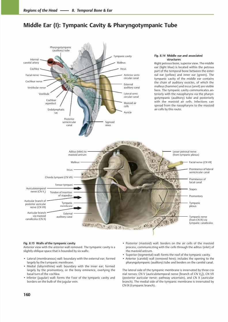
8/15/2019 Head and Neck Anatomy for Dental Medicine - Thieme; (January 26, 2010)
http://slidepdf.com/reader/full/head-and-neck-anatomy-for-dental-medicine-thieme-january-26-2010 173/384
Auricle
Externalauditory canal
Internalcarotid artery
Cochlea
Facial nerve
Cochlear nerve
Vestibular nerve
Anterior semi-circular canal
Endolymphatic
sac
Cochlearaqueduct
Posteriorsemicircular
canal
Lateral semi-circular canal
Sigmoidsinus
Mastoid aircells
Incus
Vestibule
Malleus
Pharyngotympanic(auditory) tube
Tympanic cavity
Malleus
Chorda tympani (CN VII)
Externalauditory canal
Tympanicmembrane
Tensor tympani
Prominence of lateralsemicircular canal
Tendon of insertionof stapedius
Tympanic nerve(from CN IX) viatympanic canaliculus
Tympanicplexus
Promontory
Stapes
Prominence of facial canal
Facial nerve (CN VII)
Lesser petrosal nerve(from tympanic plexus)
Aditus (inlet) tomastoid antrum
Incus
Auriculotemporalnerve (CN V
3)
Auricular branch of posterior auricular
nerve (CN VII)
Auricular branchvia mastoid
canaliculus (CN X)
Fig. 8.14 Middle ear and associatedstructures
Right petrous bone, superior view. The middle
ear (light blue) is located within the petrous
part of the temporal bone between the exter-
nal ear (yellow) and inner ear (green). The
tympanic cavity of the middle ear contains
the chain of auditory ossicles, of which the
malleus (hammer) and incus (anvil) are visible
here. The tympanic cavity communicates an-
teriorly with the nasopharynx via the pharyn-
gotympanic (auditory) tube and posteriorly
with the mastoid air cells. Infections can
spread from the nasopharynx to the mastoid
air cells by this route.
Fig. 8.15 Walls of the tympanic cavity
Anterior view with the anterior wall removed. The tympanic cavity is a
slightly oblique space that is bounded by six walls:
• Lateral (membranous) wall: boundary with the external ear; formed
largely by the tympanic membrane.
• Medial (labyrinthine) wall: boundary with the inner ear; formed
largely by the promontory, or the bony eminence, overlying the
basal turn of the cochlea.
• Inferior (jugular) wall: forms the floor of the tympanic cavity and
borders on the bulb of the jugular vein.
• Posterior (mastoid) wall: borders on the air cells of the mastoid
process, communicating with the cells through the aditus (inlet) of
the mastoid antrum.
• Superior (tegmental) wall: forms the roof of the tympanic cavity.
• Anterior (carotid) wall (removed here): includes the opening to the
pharyngotympanic (auditory) tube and borders on the carotid canal.
The lateral side of the tympanic membrane is innervated by three cra-
nial nerves: CN V (auriculotemporal nerve [branch of CN V3]), CN VII
(posterior auricular nerve; pathway uncertain), and CN X (auricular
branch). The medial side of the tympanic membrane is innervated byCN IX (tympanic branch).
160
Regions of the Head 8. Temporal Bone & Ear
Middle Ear (I): Tympanic Cavity & Pharyngotympanic Tube
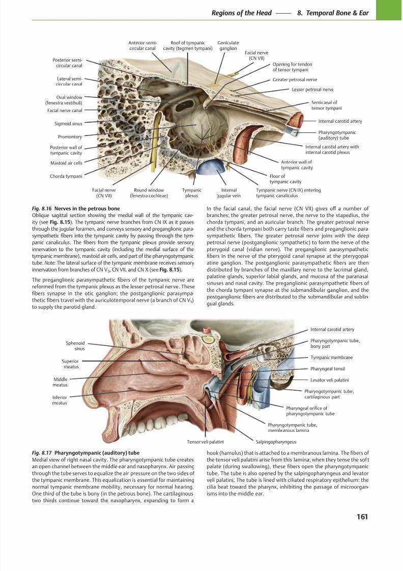
8/15/2019 Head and Neck Anatomy for Dental Medicine - Thieme; (January 26, 2010)
http://slidepdf.com/reader/full/head-and-neck-anatomy-for-dental-medicine-thieme-january-26-2010 174/384
Internal carotid artery withinternal carotid plexus
Lesser petrosal nerve
Chorda tympani
Tympanicplexus
Greater petrosal nerve
Tympanic nerve (CN IX) enteringtympanic canaliculus
Geniculateganglion
Facial nerve(CN VII)
Sigmoid sinus
Anterior semi-circular canal
Facial nerve canal
Lateral semi-circular canal
Posterior semi-circular canal
Mastoid air cells
Facial nerve(CN VII)
Round window(fenestra cochleae)
Internal jugular vein
Pharyngotympanic(auditory) tube
Internal carotid artery
Semicanal of tensor tympani
Oval window(fenestra vestibuli)
Posterior wall of tympanic cavity
Floor of tympanic cavity
Anterior wall of tympanic cavity
Promontory
Roof of tympaniccavity (tegmen tympani)
Opening for tendonof tensor tympani
Sphenoidsinus
Pharyngeal tonsil
Superiormeatus
Middlemeatus
InferiormeatusPharyngeal orifice ofpharyngotympanic tube
Tensor veli palatini
Pharyngotympanic tube,membranous lamina
Salpingopharyngeus
Tympanic membrane
Pharyngotympanic tube,bony part
Internal carotid artery
Levator veli palatini
Pharyngotympanic tube,cartilaginous part
Fig. 8.16 Nerves in the petrous bone
Oblique sagittal section showing the medial wall of the tympanic cav-
ity (see Fig. 8.15). The tympanic nerve branches from CN IX as it passes
through the jugular foramen, and conveys sensory and preganglionic para-
-
innervation to the tympanic cavity (including the medial surface of the
tympanic membrane), mastoid air cells, and part of the pharyngotympanic
tube. Note: The lateral surface of the tympanic membrane receives sensory
innervation from branches of CN V3, CN VII, and CN X (see Fig. 8.15).
-
3)to supply the parotid gland.
branches: the greater petrosal nerve, the nerve to the stapedius, the
chorda tympani, and an auricular branch. The greater petrosal nerve
-
petrosal nerve (postganglionic sympathetic) to form the nerve of the
pterygoid canal (vidian nerve). The preganglionic parasympathetic
-
palatine glands, superior labial glands, and mucosa of the paranasal
the chorda tympani synapse at the submandibular ganglion, and the
-
gual glands.
Fig. 8.17 Pharyngotympanic (auditory) tube
Medial view of right nasal cavity. The pharyngotympanic tube creates
through the tube serves to equalize the air pressure on the two sides of
the tympanic membrane. This equalization is essential for maintaining
normal tympanic membrane mobility, necessary for normal hearing.
One third of the tube is bony (in the petrous bone). The cartilaginous
tube. The tube is also opened by the salpingopharyngeus and levator
veli palatini. The tube is lined with ciliated respiratory epithelium: the
-
isms into the middle ear.
161
Regions of the Head 8. Temporal Bone & Ear
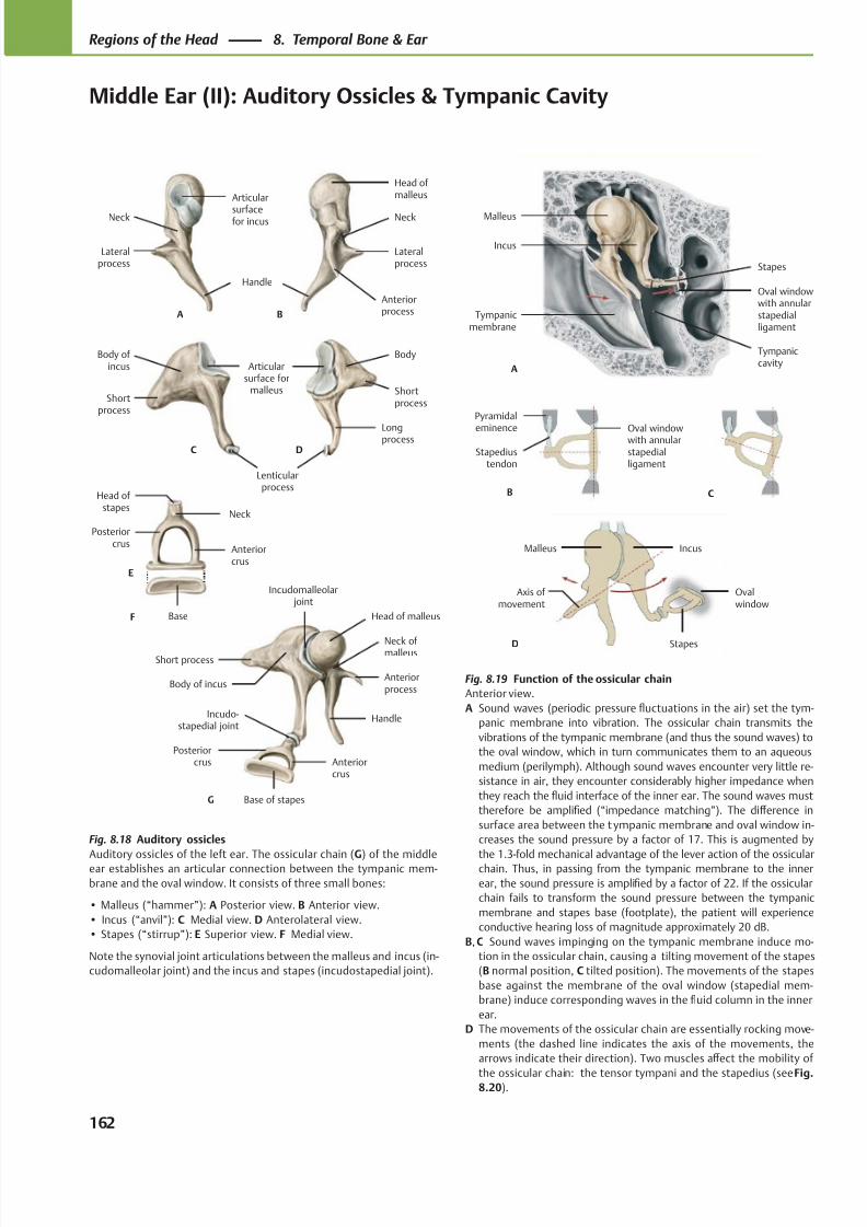
8/15/2019 Head and Neck Anatomy for Dental Medicine - Thieme; (January 26, 2010)
http://slidepdf.com/reader/full/head-and-neck-anatomy-for-dental-medicine-thieme-january-26-2010 175/384
Tympaniccavity
Oval windowwith annularstapedialligament
Stapes
Incus
Malleus
A
Tympanicmembrane
C
Stapediustendon
Pyramidal
eminence
B
Oval windowwith annularstapedialligament
D Stapes
IncusMalleus
Ovalwindow
Axis of movement
AnteriorprocessA B
Handle
Lateralprocess
Neck
Articular
surfacefor incus
Head of malleus
Lateralprocess
Neck
Articularsurface for
malleus
Longprocess
Shortprocess
Body of incus
Shortprocess
Body
C D
Lenticularprocess
Posteriorcrus
Base
Anteriorcrus
Neck
Head of stapes
E
F
Incudo-stapedial joint
Incudomalleolar joint
Posteriorcrus
Base of stapes
Anteriorcrus
Short process
Body of incusAnteriorprocess
Head of malleus
Handle
Neck of malleus
G
Fig. 8.18 Auditory ossicles
Auditory ossicles of the left ear. The ossicular chain (G) of the middleear establishes an articular connection between the tympanic mem-
brane and the oval window. It consists of three small bones:
• Malleus (“hammer”): A Posterior view. B Anterior view.
• Incus (“anvil”): C Medial view. D Anterolateral view.
• Stapes (“stirrup”): E Superior view. F Medial view.
Note the synovial joint articulations between the malleus and incus (in-
cudomalleolar joint) and the incus and stapes (incudostapedial joint).
Fig. 8.19 Function of the ossicular chain
Anterior view.
A Sound waves (periodic pressure fluctuations in the air) set the tym-
panic membrane into vibration. The ossicular chain transmits the
vibrations of the tympanic membrane (and thus the sound waves) to
the oval window, which in turn communicates them to an aqueous
medium (perilymph). Although sound waves encounter very little re-
sistance in air, they encounter considerably higher impedance when
they reach the fluid interface of the inner ear. The sound waves must
therefore be amplified (“impedance matching”). The diff erence in
surface area between the t ympanic membrane and oval window in-
creases the sound pressure by a factor of 17. This is augmented by
the 1.3-fold mechanical advantage of the lever action of the ossicularchain. Thus, in passing from the tympanic membrane to the inner
ear, the sound pressure is amplified by a factor of 22. If the ossicular
chain fails to transform the sound pressure between the tympanic
membrane and stapes base (footplate), the patient will experience
conductive hearing loss of magnitude approximately 20 dB.
B, C Sound waves impinging on the tympanic membrane induce mo-
tion in the ossicular chain, causing a tilting movement of the stapes
(B normal position, C tilted position). The movements of the stapes
base against the membrane of the oval window (stapedial mem-
brane) induce corresponding waves in the fluid column in the inner
ear.
D The movements of the ossicular chain are essentially rocking move-
ments (the dashed line indicates the axis of the movements, the
arrows indicate their direction). Two muscles aff ect the mobility of
the ossicular chain: the tensor tympani and the stapedius (see Fig.8.20).
162
Regions of the Head 8. Temporal Bone & Ear
Middle Ear (II): Auditory Ossicles & Tympanic Cavity
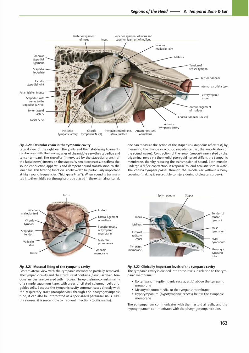
8/15/2019 Head and Neck Anatomy for Dental Medicine - Thieme; (January 26, 2010)
http://slidepdf.com/reader/full/head-and-neck-anatomy-for-dental-medicine-thieme-january-26-2010 176/384
Pyramidal eminence
Incudo-stapedial joint
Petrotympanicfissure
Anterior processof malleus
Stapedialfootplate
Facial nerve
Tympanic membrane,lateral surface
Stylomastoidartery
Stapedius withnerve to the
stapedius (CN VII)
Posteriortympanic artery
Tendon of tensor tympani
Anteriortympanic artery
Chorda tympani (CN VII)
Anterior ligamentof malleus
Tensor tympani
Internal carotid artery
Malleus
Superior ligament of incus andsuperior ligament of malleus
Incudo-malleolar joint
IncusPosterior ligament
of incus
Annularstapedial
ligament
Chordatympani (CN VII)
Stapediustendon
Malleolarstria
Chordatympani
Superiormalleolar fold
Tympanicmembrane
Malleolarprominence
Superior recessof tympanicmembrane
Lateral ligamentof malleus
Malleus
Incus
Umbo
Externalauditory
canal
Tympanicmembrane
Hypo-tympanum
Meso-tympanum
Tendon oftensortympani
StapesEpitympanum
Malleus
Incus
Pharyngo-tympanictube
Fig. 8.20 Ossicular chain in the tympanic cavity
Lateral view of the right ear. The joints and their stabilizing ligaments
can be seen with the two muscles of the middle ear—the stapedius and
tensor tympani. The stapedius (innervated by the stapedial branch of
the facial nerve) inserts on the stapes. When it contracts, it stiff ens the
sound conduction apparatus and dampens sound transmission to the
inner ear. This filtering function is believed to be particularly important
at high sound frequencies (“high-pass filter”). When sound is transmit-
ted into the middle ear through a probe placed in the external ear canal,
Fig. 8.22 Clinically important levels of the tympanic cavity
The tympanic cavity is divided into three levels in relation to the tym-
panic membrane:
• Epitympanum (epitympanic recess, attic) above the tympanic
membrane
• Mesotympanum medial to the tympanic membrane
• Hypotympanum (hypotympanic recess) below the tympanic
membrane
The epitympanum communicates with the mastoid air cells, and the
hypotympanum communicates with the pharyngotympanic tube.
Fig. 8.21 Mucosal lining of the tympanic cavity
Posterolateral view with the tympanic membrane partially removed.
The tympanic cavity and the structures it contains (ossicular chain, ten-
dons, nerves) are covered with mucosa. The epithelium consists mainly
of a simple squamous type, with areas of ciliated columnar cells and
goblet cells. Because the tympanic cavity communicates directly with
the respiratory tract (nasopharynx) through the pharyngotympanic
tube, it can also be interpreted as a specialized paranasal sinus. Like
the sinuses, it is susceptible to frequent infections (otitis media).
one can measure the action of the stapedius (stapedius reflex test) by
measuring the change in acoustic impedance (i.e., the amplification of
the sound waves). Contraction of the tensor tympani (innervated by the
trigeminal nerve via the medial pterygoid nerve) stiff ens the tympanic
membrane, thereby reducing the transmission of sound. Both muscles
undergo a reflex contraction in response to loud acoustic stimuli. Note:
The chorda tympani passes through the middle ear without a bony
covering (making it susceptible to injury during otological surgery).
163
Regions of the Head 8. Temporal Bone & Ear
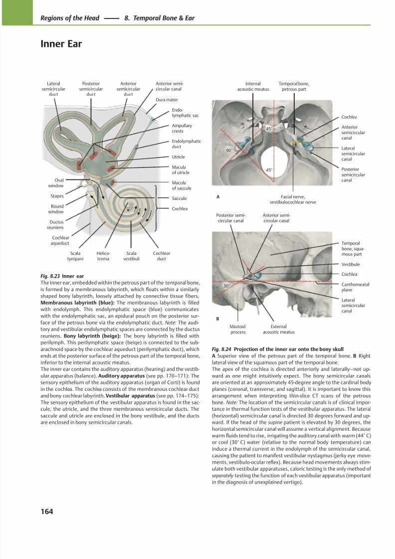
8/15/2019 Head and Neck Anatomy for Dental Medicine - Thieme; (January 26, 2010)
http://slidepdf.com/reader/full/head-and-neck-anatomy-for-dental-medicine-thieme-january-26-2010 177/384
Mastoidprocess
Externalacoustic meatus
Temporalbone, squa-mous part
Posterior semi-circular canal
Lateralsemicircularcanal
Vestibule
Canthomeatalplane
Cochlea
Anterior semi-circular canal
30°
B
Facial nerve,vestibulocochlear nerve
Temporal bone,petrous part
Internalacoustic meatus
Posteriorsemicircularcanal
Lateralsemicircularcanal
Anteriorsemicircularcanal
Cochlea
45°
90°
45°
A
Scalatympani
Scalavestibuli
Posteriorsemicircular
duct
Helico-trema
Maculaof saccule
Maculaof utricle
Ampullarycrests
Ductusreuniens
Cochlea
Cochlearduct
Roundwindow
Saccule
Ovalwindow
Utricle
Stapes
Cochlearaqueduct
Endolymphaticduct
Lateralsemicircular
duct
Anteriorsemicircular
ductDura mater
Endo-lymphatic sac
Anterior semi-circular canal
Fig. 8.24 Projection of the inner ear onto the bony skull
A Superior view of the petrous part of the temporal bone. B Right
lateral view of the squamous part of the temporal bone.
The apex of the cochlea is directed anteriorly and laterally—not up-
ward as one might intuitively expect. The bony semicircular canals
are oriented at an approximately 45-degree angle to the cardinal body
planes (coronal, transverse, and sagittal). It is important to know thisarrangement when interpreting thin-slice CT scans of the petrous
bone. Note: The location of the semicircular canals is of clinical impor-
tance in thermal function tests of the vestibular apparatus. The lateral
(horizontal) semicircular canal is directed 30 degrees forward and up-
ward. If the head of the supine patient is elevated by 30 degrees, the
horizontal semicircular canal will assume a vertical alignment. Because
warm fluids tend to rise, irrigating the auditory canal with warm (44° C)
or cool (30° C) water (relative to the normal body temperature) can
induce a thermal current in the endolymph of the semicircular canal,
causing the patient to manifest vestibular nystagmus (jerky eye move-
ments, vestibulo-ocular reflex). Because head movements always stim-
ulate both vestibular apparatuses, caloric testing is the only method of
separately testing the function of each vestibular apparatus (important
in the diagnosis of unexplained vertigo).
Fig. 8.23 Inner ear
The inner ear, embedded within the petrous part of the temporal bone,
is formed by a membranous labyrinth, which floats within a similarly
shaped bony labyrinth, loosely attached by connective tissue fibers.
Membranous labyrinth (blue): The membranous labyrinth is filled
with endolymph. This endolymphatic space (blue) communicates
with the endolymphatic sac, an epidural pouch on the posterior sur-
face of the petrous bone via the endolymphatic duct. Note: The audi-
tory and vestibular endolymphatic spaces are connected by the ductus
reuniens. Bony labyrinth (beige): The bony labyrinth is filled with
perilymph. This perilymphatic space (beige) is connected to the sub-
arachnoid space by the cochlear aqueduct (perilymphatic duct), which
ends at the posterior surface of the petrous part of the temporal bone,
inferior to the internal acoustic meatus.
The inner ear contains the auditory apparatus (hearing) and the vestib-
ular apparatus (balance). Auditory apparatus (see pp. 170–171): The
sensory epithelium of the auditory apparatus (organ of Corti) is found
in the cochlea. The cochlea consists of the membranous cochlear ductand bony cochlear labyrinth. Vestibular apparatus (see pp. 174–175):
The sensory epithelium of the vestibular apparatus is found in the sac-
cule, the utricle, and the three membranous semicircular ducts. The
saccule and utricle are enclosed in the bony vestibule, and the ducts
are enclosed in bony semicircular canals.
164
Regions of the Head 8. Temporal Bone & Ear
Inner Ear
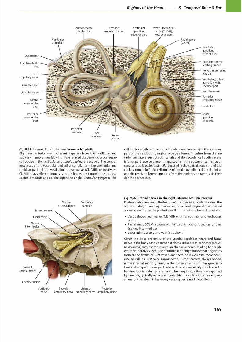
8/15/2019 Head and Neck Anatomy for Dental Medicine - Thieme; (January 26, 2010)
http://slidepdf.com/reader/full/head-and-neck-anatomy-for-dental-medicine-thieme-january-26-2010 178/384
Modiolus
Spiralganglion
of cochlea
Dura mater
Endolymphaticsac
Vestibularaqueduct
Lateralsemicircular
duct
Common crus
Posteriorsemicircular
duct
Posteriorampulla Oval
window Roundwindow
Posteriorampullary nerve
Nervus intermedius(CN VII)
Vestibularganglion,inferior part
Vestibulocochlearnerve (CN VIII),cochlear part
Facial nerve(CN VII)
Vestibularganglion,
superior part
Vestibulocochlearnerve (CN VIII),vestibular part
Cochlear commu-nicating branch
Saccular nerveUtricular nerve
Anteriorampullary nerve
Lateralampullary nerve
Anterior semi-circular duct
Internalcarotid artery
Vestibularnerve
Posteriorampullary nerve
Geniculateganglion
Greaterpetrosal nerve
Transverse crest
Facial nerve
Cochlear nerve
Sacculo-ampullary nerve
Utriculo-ampullary nerve
Nervusintermedius
Fig. 8.25 Innervation of the membranous labyrinth
vestibular spiral ganglia
Vestibular ganglion:
Fig. 8.26 Cranial nerves in the right internal acoustic meatus
acous-
tic neuroma
vestibular schwannoma
Spiral ganglia:
165
Regions of the Head 8. Temporal Bone & Ear
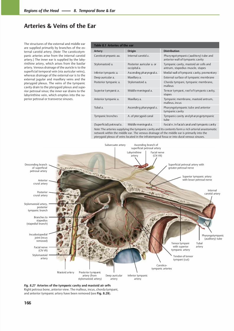
8/15/2019 Head and Neck Anatomy for Dental Medicine - Thieme; (January 26, 2010)
http://slidepdf.com/reader/full/head-and-neck-anatomy-for-dental-medicine-thieme-january-26-2010 179/384
Carotico-tympanic arteries
Stylomastoid artery,posterior
tympanic branch
Branches tostapedius
(stapedial branch)
Mastoid artery Posterior tympanicartery (from
stylomastoid artery)Deep auricular
arteryInferior tympanic
artery
Tubalartery
Pharyngotympanic(auditory) tube
Internalcarotid artery
Tensor tympaniwith superior
tympanic artery
Superior tympanic arterywith lesser petrosal nerve
Superficial petrosal artery withgreater petrosal nerve
Facial nerve(CN VII)
Labyrinthineartery
Anteriorcrural artery
Subarcuate artery
Posteriorcrural artery
Descending branchof superficial
petrosal artery
Ascending branch of superficial petrosal artery
Stylomastoidartery
Facial nerve(CN VII)
Tendon of tensortympani (cut)
Incudostapedial joint (incus
removed)
Table 8.1 Arteries of the ear
Artery Origin Distribution
Caroticotympanic aa. Internal carotid a. Pharyngotympanic (auditory) tube and
anterior wall of tympanic cavity
Stylomastoid a. Posterior auricular a. or
occipital a.
Tympanic cavity, mastoid air cells and
antrum, stapedius muscle, stapes
Inferior tympanic a. Ascending pharyngeal a. Medial wall of tympanic cavity, promontory
Deep auricular a. Maxillary a. External surface of tympanic membrane
Posterior tympanic a. Stylomastoid a. Chorda tympani, tympanic membrane,
malleus
Superior tympanic a. Middle meningeal a. Tensor tympani, roof of tympanic cavity,
stapes
Anterior tympanic a. Maxillary a. Tympanic membrane, mastoid antrum,
malleus, incus
Tubal a. Ascending pharyngeal a. Pharyngotympanic tube and anterior
tympanic cavity
Tympanic branches A. of pterygoid canal Tympanic cavity and pharyngotympanictube
(Superficial) petrosal a. Middle meningeal a. Facial n. in facial canal and tympanic cavity
Note: The arteries supplying the tympanic cavity and its contents form a rich arterial anastomotic
network within the middle ear. The venous drainage of the middle ear is primarily into the
pterygoid plexus of veins located in the infratemporal fossa or into dural venous sinuses.
The structures of the external and middle ear
are supplied primarily by branches of the ex-
ternal carotid artery. (Note: The caroticotym-
panic arteries arise from the internal carotid
artery.) The inner ear is supplied by the laby-
rinthine artery, which arises from the basilar
artery. Venous drainage of the auricle is to the
superficial temporal vein (via auricular veins),
whereas drainage of the external ear is to the
external jugular and maxillary veins and the
pterygoid plexus. The veins of the tympanic
cavity drain to the pterygoid plexus and supe-
rior petrosal sinus; the inner ear drains to the
labyrinthine vein, which empties into the su-
perior petrosal or transverse sinuses.
Fig. 8.27 Arteries of the tympanic cavity and mastoid air cells
Right petrous bone, anterior view. The malleus, incus, chorda tympani,and anterior tympanic artery have been removed (see Fig. 8.28).
166
Regions of the Head 8. Temporal Bone & Ear
Arteries & Veins of the Ear
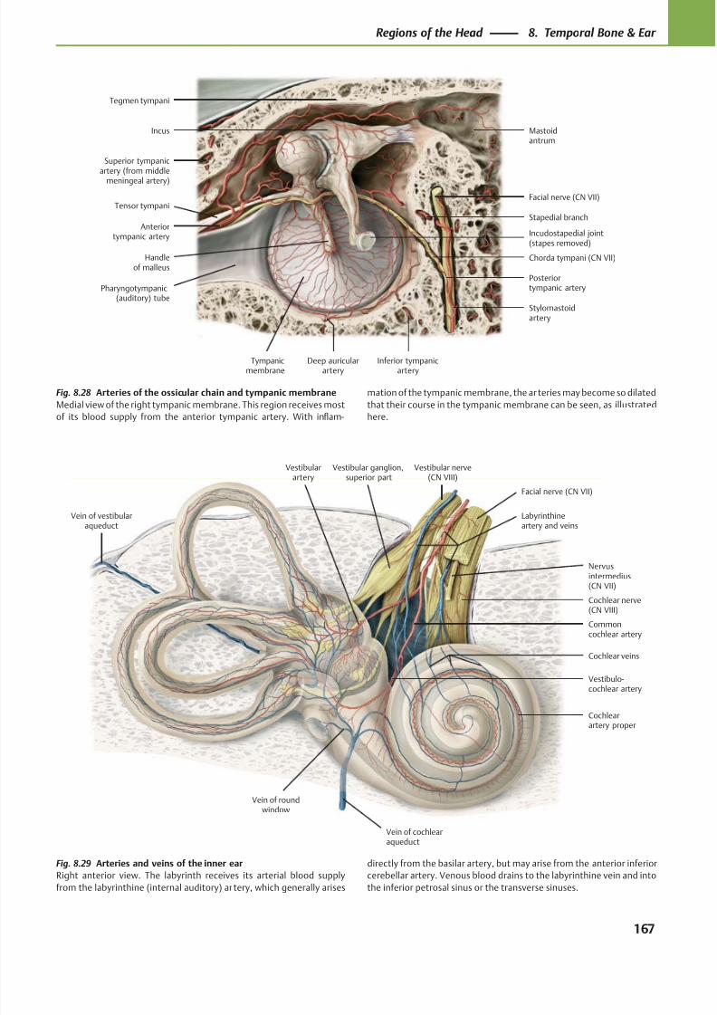
8/15/2019 Head and Neck Anatomy for Dental Medicine - Thieme; (January 26, 2010)
http://slidepdf.com/reader/full/head-and-neck-anatomy-for-dental-medicine-thieme-january-26-2010 180/384
Superior tympanicartery (from middle
meningeal artery)
Tensor tympani
Anteriortympanic artery
Pharyngotympanic(auditory) tube
Tympanicmembrane
Handleof malleus
Deep auricularartery
Incudostapedial joint(stapes removed)
Inferior tympanicartery
Stylomastoidartery
Posteriortympanic artery
Chorda tympani (CN VII)
Stapedial branch
Facial nerve (CN VII)
Tegmen tympani
Incus Mastoidantrum
Vestibular nerve(CN VIII)
Vestibular ganglion,superior part
Cochlear nerve(CN VIII)
Nervusintermedius(CN VII)
Vestibularartery
Vein of vestibularaqueduct
Vein of roundwindow
Vein of cochlearaqueduct
Vestibulo-cochlear artery
Cochlearartery proper
Commoncochlear artery
Facial nerve (CN VII)
Labyrinthineartery and veins
Cochlear veins
Fig. 8.28 Arteries of the ossicular chain and tympanic membrane
Medial view of the right tympanic membrane. This region receives most
of its blood supply from the anterior tympanic artery. With inflam-
mation of the tympanic membrane, the ar teries may become so dilated
that their course in the tympanic membrane can be seen, as illustrated
here.
Fig. 8.29 Arteries and veins of the inner ear
Right anterior view. The labyrinth receives its arterial blood supply
from the labyrinthine (internal auditory) ar tery, which generally arises
directly from the basilar artery, but may arise from the anterior inferior
cerebellar artery. Venous blood drains to the labyrinthine vein and into
the inferior petrosal sinus or the transverse sinuses.
167
Regions of the Head 8. Temporal Bone & Ear
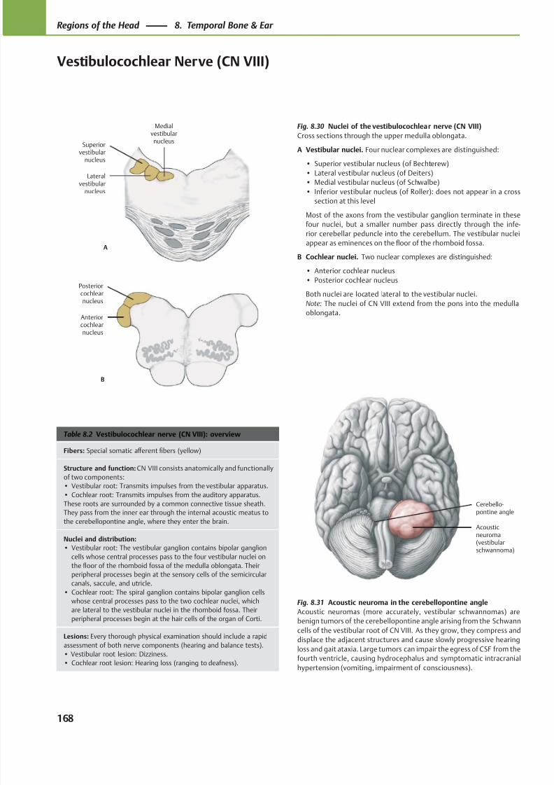
8/15/2019 Head and Neck Anatomy for Dental Medicine - Thieme; (January 26, 2010)
http://slidepdf.com/reader/full/head-and-neck-anatomy-for-dental-medicine-thieme-january-26-2010 181/384
Cerebello-pontine angle
Acousticneuroma(vestibular
schwannoma)
Medialvestibularnucleus
Lateralvestibular
nucleus
Superiorvestibular
nucleus
A
Anteriorcochlearnucleus
Posteriorcochlearnucleus
B
Table 8.2 Vestibulocochlear nerve (CN VIII): overview
Fibers: Special somatic aff erent fibers (yellow)
Structure and function: CN VIII consists anatomically and functionally
of two components:
• Vestibular root: Transmits impulses from the vestibular apparatus.
• Cochlear root: Transmits impulses from the auditory apparatus.
These roots are surrounded by a common connective tissue sheath.
They pass from the inner ear through the internal acoustic meatus to
the cerebellopontine angle, where they enter the brain.
Nuclei and distribution:
• Vestibular root: The vestibular ganglion contains bipolar ganglioncells whose central processes pass to the four vestibular nuclei on
the floor of the rhomboid fossa of the medulla oblongata. Their
peripheral processes begin at the sensory cells of the semicircular
canals, saccule, and utricle.
• Cochlear root: The spiral ganglion contains bipolar ganglion cells
whose central processes pass to the two cochlear nuclei, which
are lateral to the vestibular nuclei in the rhomboid fossa. Their
peripheral processes begin at the hair cells of the organ of Corti.
Lesions: Every thorough physical examination should include a rapid
assessment of both nerve components (hearing and balance tests).
• Vestibular root lesion: Dizziness.
• Cochlear root lesion: Hearing loss (ranging to deafness).
Fig. 8.31 Acoustic neuroma in the cerebellopontine angle
Acoustic neuromas (more accurately, vestibular schwannomas) are
benign tumors of the cerebellopontine angle arising from the Schwann
cells of the vestibular root of CN VIII. As they grow, they compress and
displace the adjacent structures and cause slowly progressive hearing
loss and gait ataxia. Large tumors can impair the egress of CSF from the
fourth ventricle, causing hydrocephalus and symptomatic intracranial
hypertension (vomiting, impairment of consciousness).
Fig. 8.30 Nuclei of the vestibulocochlear nerve (CN VIII)
Cross sections through the upper medulla oblongata.
A Vestibular nuclei. Four nuclear complexes are distinguished:
• Superior vestibular nucleus (of Bechterew)
• Lateral vestibular nucleus (of Deiters)
• Medial vestibular nucleus (of Schwalbe)
• Inferior vestibular nucleus (of Roller): does not appear in a cross
section at this level
Most of the axons from the vestibular ganglion terminate in these
four nuclei, but a smaller number pass directly through the infe-
rior cerebellar peduncle into the cerebellum. The vestibular nuclei
appear as eminences on the floor of the rhomboid fossa.
B Cochlear nuclei. Two nuclear complexes are distinguished:
• Anterior cochlear nucleus• Posterior cochlear nucleus
Both nuclei are located lateral to the vestibular nuclei.
Note: The nuclei of CN VIII extend from the pons into the medulla
oblongata.
168
Regions of the Head 8. Temporal Bone & Ear
Vestibulocochlear Nerve (CN VIII)
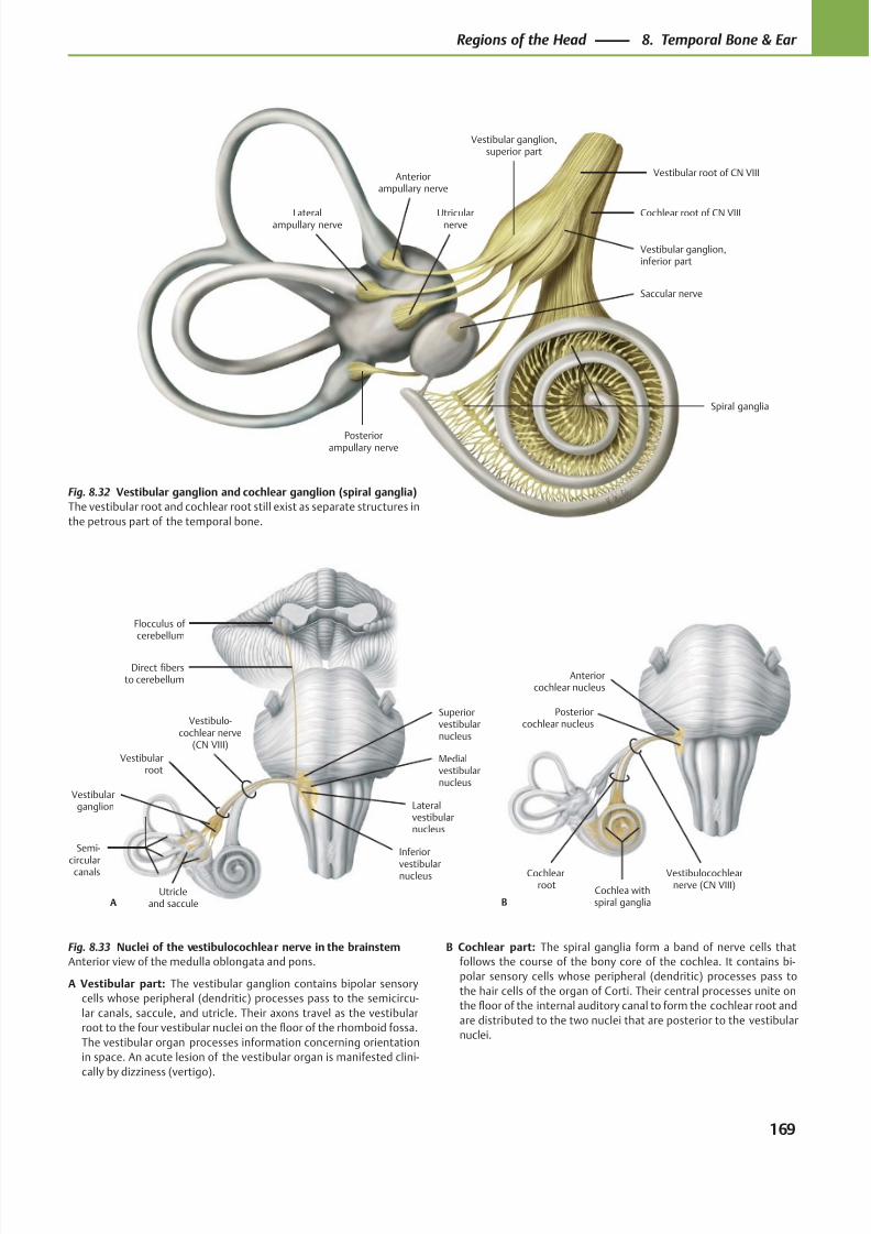
8/15/2019 Head and Neck Anatomy for Dental Medicine - Thieme; (January 26, 2010)
http://slidepdf.com/reader/full/head-and-neck-anatomy-for-dental-medicine-thieme-january-26-2010 182/384
Posteriorcochlear nucleus
Anteriorcochlear nucleus
B
Vestibulocochlearnerve (CN VIII)
Cochlearroot
Cochlea withspiral ganglia
Flocculus of cerebellum
Inferior
vestibularnucleus
Medialvestibularnucleus
Lateralvestibularnucleus
Superiorvestibularnucleus
Vestibulo-cochlear nerve
(CN VIII)
A
Semi-
circularcanals
Vestibularganglion
Vestibularroot
Direct fibersto cerebellum
Utricleand saccule
Vestibular ganglion,superior part
Cochlear root of CN VIII
Spiral ganglia
Vestibular root of CN VIII
Saccular nerve
Utricularnerve
Posteriorampullary nerve
Lateralampullary nerve
Anteriorampullary nerve
Vestibular ganglion,inferior part
Fig. 8.32 Vestibular ganglion and cochlear ganglion (spiral ganglia)
The vestibular root and cochlear root still exist as separate structures in
the petrous part of the temporal bone.
Fig. 8.33 Nuclei of the vestibulocochlear nerve in the brainstem
Anterior view of the medulla oblongata and pons.
A Vestibular part: The vestibular ganglion contains bipolar sensory
cells whose peripheral (dendritic) processes pass to the semicircu-
lar canals, saccule, and utricle. Their axons travel as the vestibular
root to the four vestibular nuclei on the floor of the rhomboid fossa.
The vestibular organ processes information concerning orientation
in space. An acute lesion of the vestibular organ is manifested clini-
cally by dizziness (vertigo).
B Cochlear part: The spiral ganglia form a band of nerve cells that
follows the course of the bony core of the cochlea. It contains bi-
polar sensory cells whose peripheral (dendritic) processes pass to
the hair cells of the organ of Corti. Their central processes unite on
the floor of the internal auditory canal to form the cochlear root and
are distributed to the two nuclei that are posterior to the vestibular
nuclei.
169
Regions of the Head 8. Temporal Bone & Ear
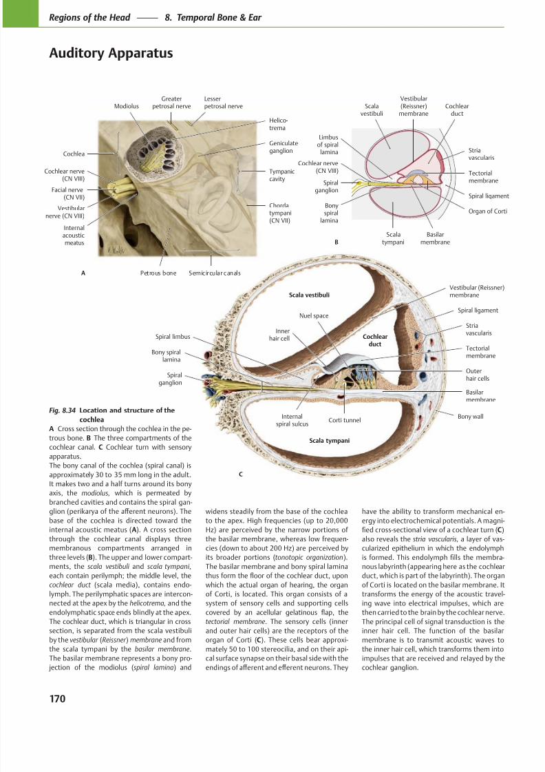
8/15/2019 Head and Neck Anatomy for Dental Medicine - Thieme; (January 26, 2010)
http://slidepdf.com/reader/full/head-and-neck-anatomy-for-dental-medicine-thieme-january-26-2010 183/384
Nuel space
Corti tunnel
Innerhair cell Cochlear
ductTectorialmembrane
Internalspiral sulcus
Spiral limbus
Vestibular (Reissner)membrane
Bony spirallamina
Spiralganglion
Basilarmembrane
Striavascularis
Spiral ligament
Bony wall
Scala tympani
Scala vestibuli
C
Outerhair cells
Greaterpetrosal nerve
Cochlea
Cochlear nerve(CN VIII)
Facial nerve(CN VII)
Vestibularnerve (CN VIII)
Internalacousticmeatus
Petrous bone Semicircular canals
Chordatympani(CN VII)
Tympaniccavity
Geniculateganglion
ModiolusLesserpetrosal nerve
A
Helico-trema
Vestibular(Reissner)
membrane
Limbusof spiral
lamina
Spiralganglion
Cochlear nerve(CN VIII)
Bonyspiral
lamina
Scalatympani
Basilarmembrane
Organ of Corti
Spiral ligament
Tectorialmembrane
Cochlearduct
Striavascularis
Scalavestibuli
B
Fig. 8.34 Location and structure of the
cochlea
A Cross section through the cochlea in the pe-
trous bone. B The three compartments of the
cochlear canal. C Cochlear turn with sensory
apparatus.
The bony canal of the cochlea (spiral canal) is
approximately 30 to 35 mm long in the adult.
It makes two and a half turns around its bony
axis, the modiolus, which is permeated by
branched cavities and contains the spiral gan-
base of the cochlea is directed toward the
internal acoustic meatus (A). A cross section
through the cochlear canal displays threemembranous compartments arranged in
three levels (B). The upper and lower compart-
ments, the scala vestibuli and scala tympani,
each contain perilymph; the middle level, the
cochlear duct (scala media), contains endo-
lymph. The perilymphatic spaces are intercon-
nected at the apex by the helicotrema, and the
endolymphatic space ends blindly at the apex.
The cochlear duct, which is triangular in cross
section, is separated from the scala vestibuli
by the vestibular (Reissner ) membrane and from
the scala tympani by the basilar membrane.
The basilar membrane represents a bony pro-
jection of the modiolus (spiral lamina) and
widens steadily from the base of the cochlea
to the apex. High frequencies (up to 20,000
Hz) are perceived by the narrow portions of
the basilar membrane, whereas low frequen-cies (down to about 200 Hz) are perceived by
its broader portions (tonotopic organization).
The basilar membrane and bony spiral lamina
which the actual organ of hearing, the organ
of Corti, is located. This organ consists of a
system of sensory cells and supporting cells
tectorial membrane. The sensory cells (inner
and outer hair cells) are the receptors of the
organ of Corti (C). These cells bear approxi-
mately 50 to 100 stereocilia, and on their api-
cal surface synapse on their basal side with the
have the ability to transform mechanical en-
ergy into electrochemical potentials. A magni-
C)
also reveals the stria vascularis, a layer of vas-cularized epithelium in which the endolymph
-
nous labyrinth (appearing here as the cochlear
duct, which is part of the labyrinth). The organ
of Corti is located on the basilar membrane. It
transforms the energy of the acoustic travel-
ing wave into electrical impulses, which are
then carried to the brain by the cochlear nerve.
The principal cell of signal transduction is the
inner hair cell. The function of the basilar
membrane is to transmit acoustic waves to
the inner hair cell, which transforms them into
impulses that are received and relayed by the
cochlear ganglion.
170
Regions of the Head 8. Temporal Bone & Ear
Auditory Apparatus
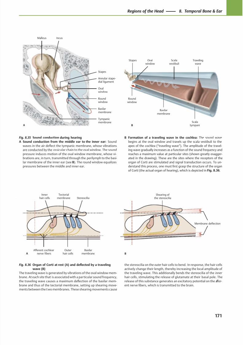
8/15/2019 Head and Neck Anatomy for Dental Medicine - Thieme; (January 26, 2010)
http://slidepdf.com/reader/full/head-and-neck-anatomy-for-dental-medicine-thieme-january-26-2010 184/384
Tympanicmembrane
Roundwindow
Ovalwindow
Annular stape-dial ligament
Stapes
IncusMalleus
A
Basilarmembrane
B
Basilarmembrane
Roundwindow
Travelingwave
Scalatympani
Scalavestibuli
Ovalwindow
Stapes
Afferent cochlearnerve fibers
Innerhair cells
Outerhair cells
Basilarmembrane
StereociliaTectorial
membrane
A
Membrane deflection
Shearing of the stereocilia
B
Fig. 8.35 Sound conduction during hearing
A Sound conduction from the middle ear to the inner ear: Sound
waves in the air deflect the tympanic membrane, whose vibrations
are conducted by the ossicular chain to the oval window. The sound
pressure induces motion of the oval window membrane, whose vi-
brations are, in turn, transmitted through the perilymph to the basi-
lar membrane of the inner ear (see B). The round window equalizes
pressures between the middle and inner ear.
Fig. 8.36 Organ of Corti at rest (A) and deflected by a traveling
wave (B)
The traveling wave is generated by vibrations of the oval window mem-
brane. At each site that is associated with a par ticular sound frequency,
the traveling wave causes a maximum deflection of the basilar mem-
brane and thus of the tectorial membrane, setting up shearing move-
ments between the two membranes. These shearing movements cause
B Formation of a traveling wave in the cochlea: The sound wave
begins at the oval window and travels up the scala vestibuli to the
apex of the cochlea (“traveling wave”). The amplitude of the travel-
ing wave gradually increases as a function of the sound frequency and
reaches a maximum value at particular sites (shown greatly exagger-
ated in the drawing). These are the sites where the receptors of the
organ of Corti are stimulated and signal transduction occurs. To un-
derstand this process, one must first grasp the structure of the organ
of Corti (the actual organ of hearing), which is depicted in Fig. 8.36.
the stereocilia on the outer hair cells to bend. In response, the hair cells
actively change their length, thereby increasing the local amplitude of
the traveling wave. This additionally bends the stereocilia of the inner
hair cells, stimulating the release of glutamate at their basal pole. The
release of this substance generates an excitatory potential on the aff er-
ent nerve fibers, which is transmitted to the brain.
171
Regions of the Head 8. Temporal Bone & Ear
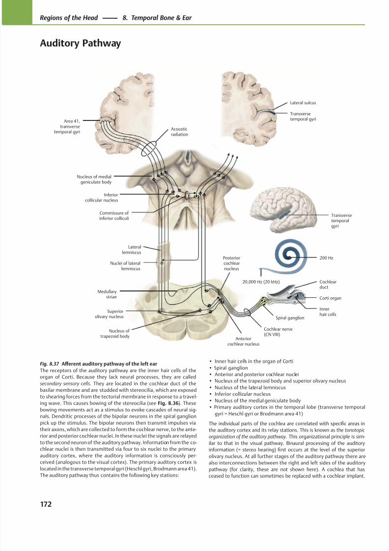
8/15/2019 Head and Neck Anatomy for Dental Medicine - Thieme; (January 26, 2010)
http://slidepdf.com/reader/full/head-and-neck-anatomy-for-dental-medicine-thieme-january-26-2010 185/384
Acousticradiation
Nucleus of medialgeniculate body
Inferiorcollicular nucleus
Nuclei of laterallemniscus
Superiorolivary nucleus
Nucleus of trapezoid body
Corti organ
Anteriorcochlear nucleus
Cochlear nerve(CN VIII)
Spiral ganglion
Posteriorcochlearnucleus
Medullarystriae
20,000 Hz (20 kHz) Cochlear
duct
200 Hz
Laterallemniscus
Commissure of inferior colliculi
Area 41,transverse
temporal gyri
Innerhair cells
Transversetemporalgyri
Transversetemporal gyri
Lateral sulcus
Fig. 8.37 Aff erent auditory pathway of the left ear
The receptors of the auditory pathway are the inner hair cells of the
organ of Corti. Because they lack neural processes, they are called
secondary sensory cells. They are located in the cochlear duct of thebasilar membrane and are studded with stereocilia, which are exposed
to shearing forces from the tectorial membrane in response to a travel-
ing wave. This causes bowing of the stereocilia (see Fig. 8.36). These
bowing movements act as a stimulus to evoke cascades of neural sig-
nals. Dendritic processes of the bipolar neurons in the spiral ganglion
pick up the stimulus. The bipolar neurons then transmit impulses via
their axons, which are collected to form the cochlear nerve, to the ante-
rior and posterior cochlear nuclei. In these nuclei the signals are relayed
to the second neuron of the auditory pathway. Information from the co-
chlear nuclei is then transmitted via four to six nuclei to the primary
auditory cortex, where the auditory information is consciously per-
ceived (analogous to the visual cortex). The primary auditory cortex is
located in the transverse temporal gyri (Heschl gyri, Brodmann area 41).
The auditory pathway thus contains the following key stations:
• Inner hair cells in the organ of Corti
• Spiral ganglion
• Anterior and posterior cochlear nuclei
• Nucleus of the trapezoid body and superior olivary nucleus
• Nucleus of the lateral lemniscus• Inferior collicular nucleus
• Nucleus of the medial geniculate body
• Primary auditory cortex in the temporal lobe (transverse temporal
gyri = Heschl gyri or Brodmann area 41)
The individual parts of the cochlea are correlated with specific areas in
the auditory cortex and its relay stations. This is known as the tonotopic
organization of the auditory pathway. This organizational principle is sim-
ilar to that in the visual pathway. Binaural processing of the auditory
information (= stereo hearing) first occurs at the level of the superior
olivary nucleus. At all further stages of the auditory pathway there are
also interconnections between the right and left sides of the auditory
pathway (for clarity, these are not shown here). A cochlea that has
ceased to function can sometimes be replaced with a cochlear implant.
172
Regions of the Head 8. Temporal Bone & Ear
Auditory Pathway
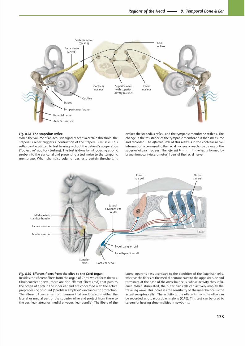
8/15/2019 Head and Neck Anatomy for Dental Medicine - Thieme; (January 26, 2010)
http://slidepdf.com/reader/full/head-and-neck-anatomy-for-dental-medicine-thieme-january-26-2010 186/384
Facialnucleus
Cochlearnucleus
Facial nerve(CN VII)
Stapes
Stapedius muscle
Tympanic membrane
Cochlea
Cochlear nerve(CN VIII)
Superior olivewith superior
olivary nucleus
Facialnucleus
Stapedial nerve
Medial olivo-cochlear bundle
Superiorolive
Medial neuron
Type I ganglion cell
Type II ganglion cell
Cochlear nerve
Innerhair cell
Outerhair cell
Lateral neuron
Lateralolivocochlear
bundle
Fig. 8.38 The stapedius reflex
When the volume of an acoustic signal reaches a certain threshold, the
stapedius reflex triggers a contraction of the stapedius muscle. This
reflex can be utilized to test hearing without the patient’s cooperation
(“objective” auditory testing). The test is done by introducing a sonic
probe into the ear canal and presenting a test noise to the tympanic
membrane. When the noise volume reaches a certain threshold, it
Fig. 8.39 Eff erent fibers from the olive to the Corti organ
Besides the aff erent fibers from the organ of Corti, which form the ves-
tibulocochlear nerve, there are also eff erent fibers (red) that pass to
the organ of Corti in the inner ear and are concerned with the active
preprocessing of sound (“cochlear amplifier”) and acoustic protection.
The eff erent fibers arise from neurons that are located in either the
lateral or medial part of the superior olive and project from there to
the cochlea (lateral or medial olivocochlear bundle). The fibers of the
evokes the stapedius reflex, and the tympanic membrane stiff ens. The
change in the resistance of the tympanic membrane is then measured
and recorded. The aff erent limb of this reflex is in the cochlear nerve.
Information is conveyed to the facial nucleus on each side by way of the
superior olivary nucleus. The eff erent limb of this reflex is formed by
branchiomotor (visceromotor) fibers of the facial nerve.
lateral neurons pass uncrossed to the dendrites of the inner hair cells,
whereas the fibers of the medial neurons cross to the opposite side and
terminate at the base of the outer hair cells, whose activity they influ-
ence. When stimulated, the outer hair cells can actively amplify the
traveling wave. This increases the sensitivity of the inner hair cells (the
actual receptor cells). The activity of the eff erents from the olive can
be recorded as otoacoustic emissions (OAE). This test can be used to
screen for hearing abnormalities in newborns.
173
Regions of the Head 8. Temporal Bone & Ear
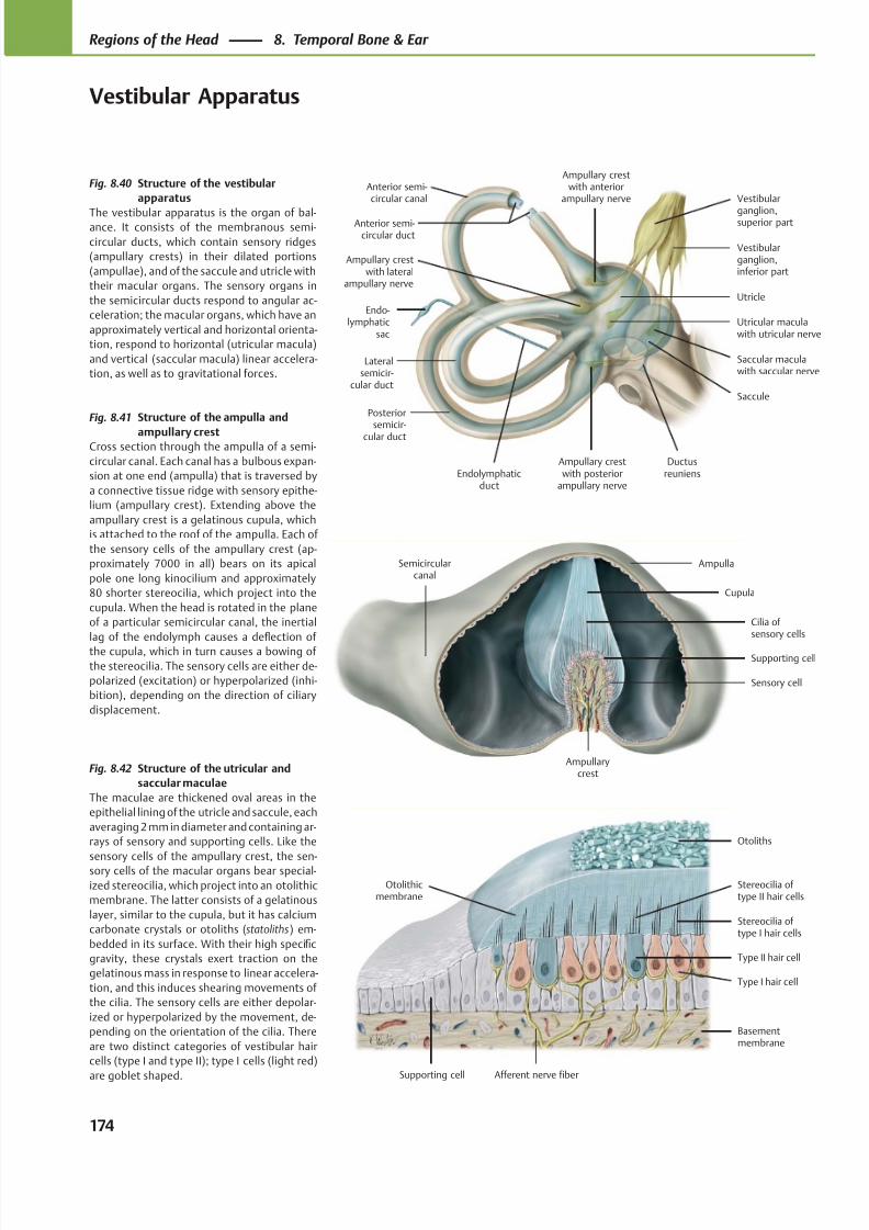
8/15/2019 Head and Neck Anatomy for Dental Medicine - Thieme; (January 26, 2010)
http://slidepdf.com/reader/full/head-and-neck-anatomy-for-dental-medicine-thieme-january-26-2010 187/384
Ampullary crestwith lateral
ampullary nerve
Lateralsemicir-
cular duct
Posteriorsemicir-
cular duct
Ampullary crestwith posterior
ampullary nerve
Ductusreuniens
Saccular maculawith saccular nerve
Saccule
Utricle
Vestibularganglion,inferior part
Vestibular
ganglion,superior part
Utricular maculawith utricular nerve
Ampullary crestwith anterior
ampullary nerve
Endo-lymphatic
sac
Endolymphaticduct
Anterior semi-circular duct
Anterior semi-circular canal
Semicircularcanal
Ampullarycrest
Sensory cell
Supporting cell
Cilia of sensory cells
Ampulla
Cupula
Basementmembrane
Afferent nerve fiber
Type I hair cell
Type II hair cell
Stereocilia of type I hair cells
Otoliths
Stereocilia of type II hair cells
Supporting cell
Otolithicmembrane
Fig. 8.40 Structure of the vestibular
apparatus
The vestibular apparatus is the organ of bal-ance. It consists of the membranous semi-
circular ducts, which contain sensory ridges
(ampullary crests) in their dilated portions
(ampullae), and of the saccule and utricle with
their macular organs. The sensory organs in
the semicircular ducts respond to angular ac-
celeration; the macular organs, which have an
approximately vertical and horizontal orienta-
tion, respond to horizontal (utricular macula)
and vertical (saccular macula) linear accelera-
tion, as well as to gravitational forces.
Fig. 8.41 Structure of the ampulla and
ampullary crestCross section through the ampulla of a semi-
circular canal. Each canal has a bulbous expan-
sion at one end (ampulla) that is traversed by
a connective tissue ridge with sensory epithe-
lium (ampullary crest). Extending above the
ampullary crest is a gelatinous cupula, which
is attached to the roof of the ampulla. Each of
the sensory cells of the ampullary crest (ap-
proximately 7000 in all) bears on its apical
pole one long kinocilium and approximately
80 shorter stereocilia, which project into the
cupula. When the head is rotated in the plane
of a particular semicircular canal, the inertial
lag of the endolymph causes a deflection of
the cupula, which in turn causes a bowing of
the stereocilia. The sensory cells are either de-
polarized (excitation) or hyperpolarized (inhi-
bition), depending on the direction of ciliary
displacement.
Fig. 8.42 Structure of the utricular and
saccular maculae
The maculae are thickened oval areas in the
epithelial lining of the utricle and saccule, each
averaging 2 mm in diameter and containing ar-
rays of sensory and supporting cells. Like the
sensory cells of the ampullary crest, the sen-sory cells of the macular organs bear special-
ized stereocilia, which project into an otolithic
membrane. The latter consists of a gelatinous
layer, similar to the cupula, but it has calcium
carbonate crystals or otoliths (statoliths) em-
bedded in its surface. With their high specific
gravity, these crystals exert traction on the
gelatinous mass in response to linear accelera-
tion, and this induces shearing movements of
the cilia. The sensory cells are either depolar-
ized or hyperpolarized by the movement, de-
pending on the orientation of the cilia. There
are two distinct categories of vestibular hair
cells (type I and type II); type I cells (light red)
are goblet shaped.
174
Regions of the Head 8. Temporal Bone & Ear
Vestibular Apparatus
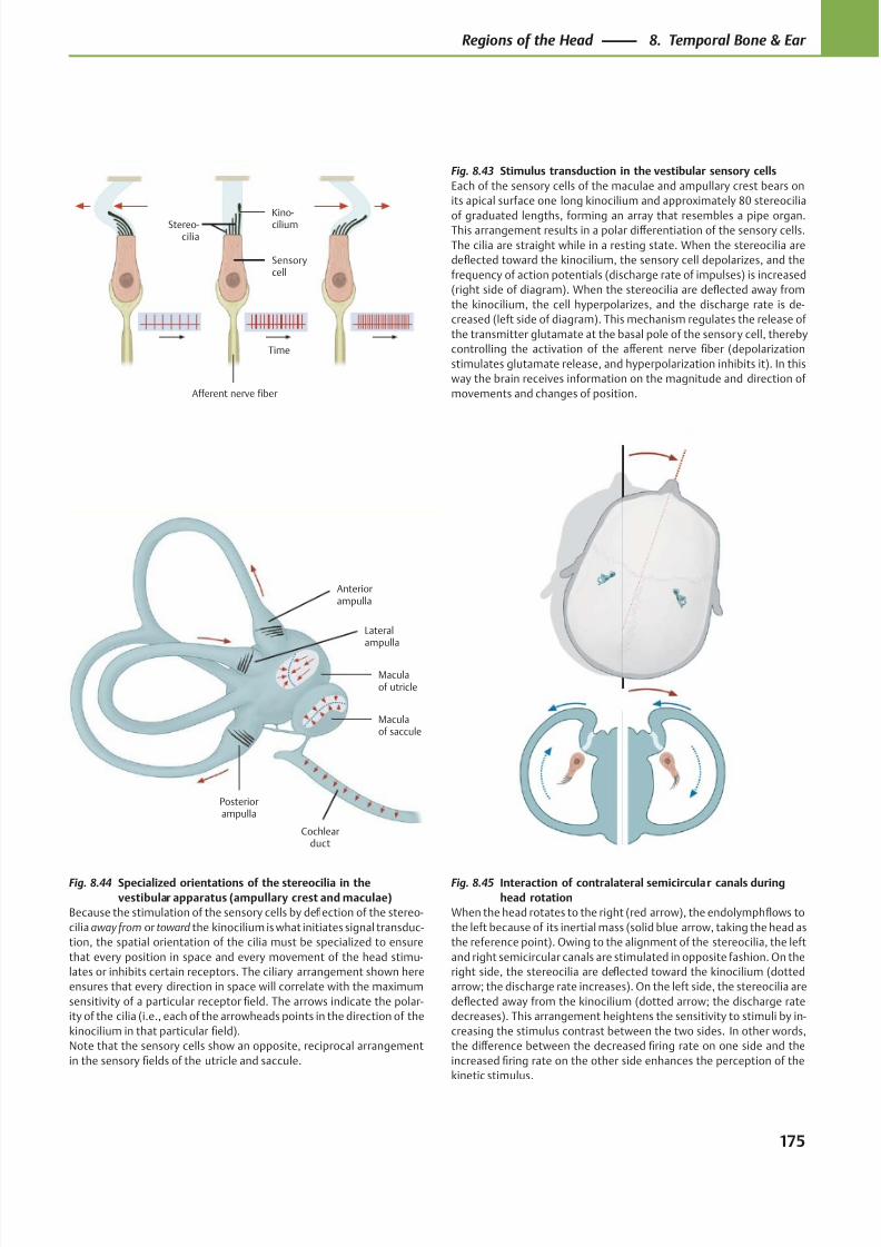
8/15/2019 Head and Neck Anatomy for Dental Medicine - Thieme; (January 26, 2010)
http://slidepdf.com/reader/full/head-and-neck-anatomy-for-dental-medicine-thieme-january-26-2010 188/384
Time
Afferent nerve fiber
Stereo-cilia
Kino-cilium
Sensorycell
Posteriorampulla
Cochlearduct
Maculaof saccule
Maculaof utricle
Anteriorampulla
Lateralampulla
Fig. 8.44 Specialized orientations of the stereocilia in the
vestibular apparatus (ampullary crest and maculae)
Because the stimulation of the sensory cells by deflection of the stereo-
cilia away from or toward the kinocilium is what initiates signal transduc-
tion, the spatial orientation of the cilia must be specialized to ensure
that every position in space and every movement of the head stimu-
lates or inhibits certain receptors. The ciliary arrangement shown here
ensures that every direction in space will correlate with the maximum
sensitivity of a particular receptor field. The arrows indicate the polar-
ity of the cilia (i.e., each of the arrowheads points in the direction of the
kinocilium in that particular field).
Note that the sensory cells show an opposite, reciprocal arrangement
in the sensory fields of the utricle and saccule.
Fig. 8.45 Interaction of contralateral semicircular canals during
head rotation
When the head rotates to the right (red arrow), the endolymph flows to
the left because of its inertial mass (solid blue arrow, taking the head as
the reference point). Owing to the alignment of the stereocilia, the left
and right semicircular canals are stimulated in opposite fashion. On the
right side, the stereocilia are deflected toward the kinocilium (dotted
arrow; the discharge rate increases). On the left side, the stereocilia are
deflected away from the kinocilium (dotted arrow; the discharge rate
decreases). This arrangement heightens the sensitivity to stimuli by in-
creasing the stimulus contrast between the two sides. In other words,
the diff erence between the decreased firing rate on one side and the
increased firing rate on the other side enhances the perception of the
kinetic stimulus.
Fig. 8.43 Stimulus transduction in the vestibular sensory cells
Each of the sensory cells of the maculae and ampullary crest bears on
its apical surface one long kinocilium and approximately 80 stereocilia
of graduated lengths, forming an array that resembles a pipe organ.This arrangement results in a polar diff erentiation of the sensory cells.
The cilia are straight while in a resting state. When the stereocilia are
deflected toward the kinocilium, the sensory cell depolarizes, and the
frequency of action potentials (discharge rate of impulses) is increased
(right side of diagram). When the stereocilia are deflected away from
the kinocilium, the cell hyperpolarizes, and the discharge rate is de-
creased (left side of diagram). This mechanism regulates the release of
the transmitter glutamate at the basal pole of the sensory cell, thereby
controlling the activation of the aff erent nerve fiber (depolarization
stimulates glutamate release, and hyperpolarization inhibits it). In this
way the brain receives information on the magnitude and direction of
movements and changes of position.
175
Regions of the Head 8. Temporal Bone & Ear
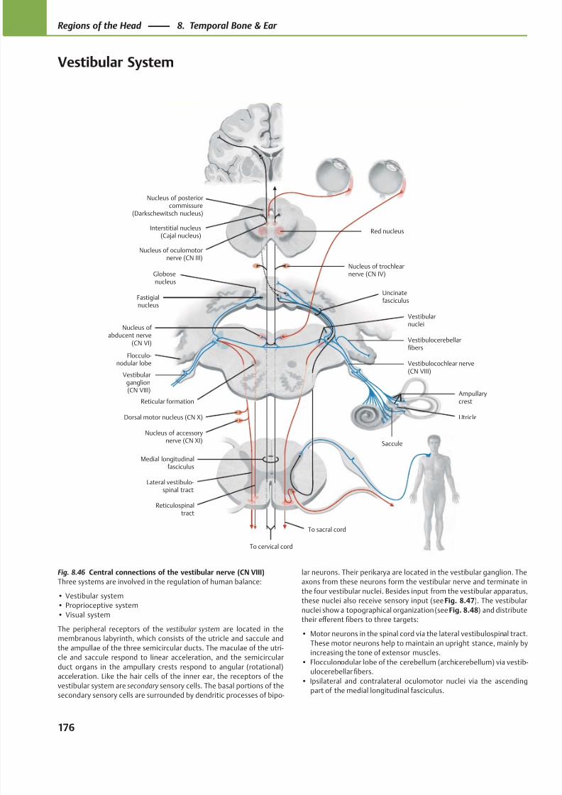
8/15/2019 Head and Neck Anatomy for Dental Medicine - Thieme; (January 26, 2010)
http://slidepdf.com/reader/full/head-and-neck-anatomy-for-dental-medicine-thieme-january-26-2010 189/384
Nucleus of posteriorcommissure
(Darkschewitsch nucleus)
Interstitial nucleus(Cajal nucleus)
Globosenucleus
Fastigialnucleus
Flocculo-nodular lobe
Dorsal motor nucleus (CN X)
Vestibularganglion(CN VIII)
Nucleus of accessorynerve (CN XI)
Medial longitudinalfasciculus
Lateral vestibulo-spinal tract
Reticulospinal tract
Vestibulocochlear nerve(CN VIII)
To cervical cord
To sacral cord
Saccule
Utricle
AmpullarycrestReticular formation
Vestibularnuclei
Nucleus of abducent nerve
(CN VI)
Uncinatefasciculus
Nucleus of trochlearnerve (CN IV)
Nucleus of oculomotornerve (CN III)
Vestibulocerebellarfibers
Red nucleus
Fig. 8.46 Central connections of the vestibular nerve (CN VIII)
Three systems are involved in the regulation of human balance:
• Vestibular system
• Proprioceptive system
• Visual system
The peripheral receptors of the vestibular system are located in the
membranous labyrinth, which consists of the utricle and saccule and
the ampullae of the three semicircular ducts. The maculae of the utri-
cle and saccule respond to linear acceleration, and the semi circular
duct organs in the ampullary crests respond to an gular (rotational)
acceleration. Like the hair cells of the inner ear, the receptors of the
vestibular system are secondary sensory cells. The basal portions of the
secondary sensory cells are surrounded by dendritic processes of bipo-
lar neurons. Their perikarya are located in the vestibular ganglion. The
axons from these neurons form the vestibular nerve and terminate in
the four vestibular nuclei. Besides input from the vestibular apparatus,
these nuclei also receive sensory input (see Fig. 8.47). The vestibular
nuclei show a topographical organization (see Fig. 8.48) and distribute
their eff erent fibers to three targets:
• Motor neurons in the spinal cord via the lateral vestibulospinal tract.
These motor neurons help to maintain an upright stance, mainly by
increasing the tone of extensor muscles.
• Flocculonodular lobe of the cerebellum (archicerebellum) via vestib-
ulocerebellar fibers.
• Ipsilateral and contralateral oculomotor nuclei via the ascending
part of the medial longitudinal fasciculus.
176
Regions of the Head 8. Temporal Bone & Ear
Vestibular System
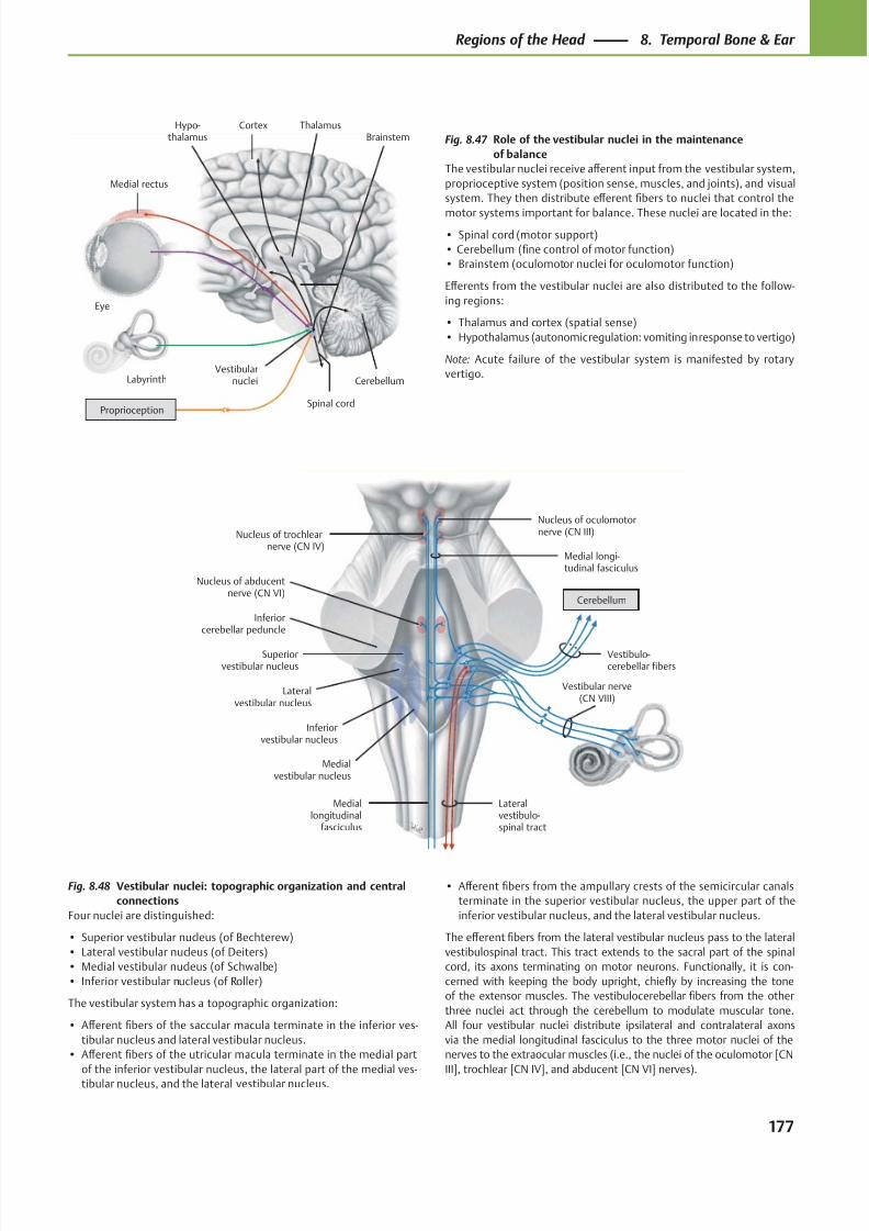
8/15/2019 Head and Neck Anatomy for Dental Medicine - Thieme; (January 26, 2010)
http://slidepdf.com/reader/full/head-and-neck-anatomy-for-dental-medicine-thieme-january-26-2010 190/384
Nucleus of oculomotornerve (CN III)Nucleus of trochlear
nerve (CN IV)
Inferiorcerebellar peduncle
Nucleus of abducentnerve (CN VI)
Superiorvestibular nucleus
Lateralvestibular nucleus
Inferiorvestibular nucleus
Medialvestibular nucleus
Mediallongitudinal
fasciculus
Lateralvestibulo-spinal tract
Medial longi-tudinal fasciculus
Vestibulo-cerebellar fibers
Cerebellum
Vestibular nerve(CN VIII)
CortexHypo-thalamus
Medial rectus
Eye
Labyrinth
Spinal cord
Vestibularnuclei Cerebellum
ThalamusBrainstem
Proprioception
Fig. 8.48 Vestibular nuclei: topographic organization and central
connections
Four nuclei are distinguished:
• Superior vestibular nucleus (of Bechterew)
• Lateral vestibular nucleus (of Deiters)
• Medial vestibular nucleus (of Schwalbe)
• Inferior vestibular nucleus (of Roller)
The vestibular system has a topographic organization:
• Aff erent fibers of the saccular macula terminate in the inferior ves-
tibular nucleus and lateral vestibular nucleus.
• Aff erent fibers of the utricular macula terminate in the medial part
of the inferior vestibular nucleus, the lateral part of the medial ves-
tibular nucleus, and the lateral vestibular nucleus.
• Aff erent fibers from the ampullary crests of the semicircular canals
terminate in the superior vestibular nucleus, the upper part of the
inferior vestibular nucleus, and the lateral vestibular nucleus.
The eff erent fibers from the lateral vestibular nucleus pass to the lateral
vestibulospinal tract. This tract extends to the sacral part of the spinal
cord, its axons terminating on motor neurons. Functionally, it is con-
cerned with keeping the body upright, chiefly by increasing the tone
of the extensor muscles. The vestibulocerebellar fibers from the other
three nuclei act through the cerebellum to modulate muscular tone.
All four vestibular nuclei distribute ipsilateral and contralateral axons
via the medial longitudinal fasciculus to the three motor nuclei of the
nerves to the extraocular muscles (i.e., the nuclei of the oculomotor [CN
III], trochlear [CN IV], and abducent [CN VI] nerves).
Fig. 8.47 Role of the vestibular nuclei in the maintenance
of balance
The vestibular nuclei receive aff erent input from the vestibular system,
proprioceptive system (position sense, muscles, and joints), and visual
system. They then distribute eff erent fibers to nuclei that control the
motor systems important for balance. These nuclei are located in the:
• Spinal cord (motor support)
• Cerebellum (fine control of motor function)
• Brainstem (oculomotor nuclei for oculomotor function)
Eff erents from the vestibular nuclei are also distributed to the follow-
ing regions:
• Thalamus and cortex (spatial sense)
• Hypothalamus (autonomic regulation: vomiting in response to vertigo)
Note: Acute failure of the vestibular system is manifested by rotary
vertigo.
177
Regions of the Head 8. Temporal Bone & Ear
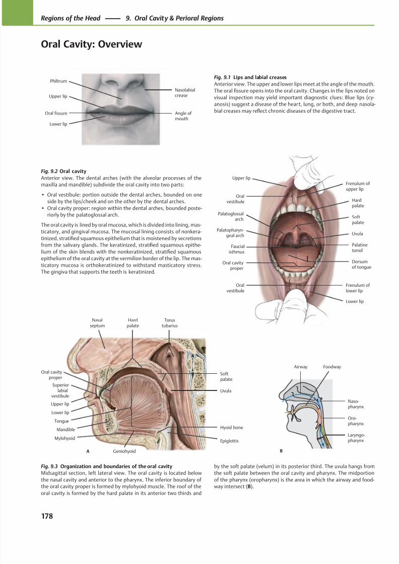
8/15/2019 Head and Neck Anatomy for Dental Medicine - Thieme; (January 26, 2010)
http://slidepdf.com/reader/full/head-and-neck-anatomy-for-dental-medicine-thieme-january-26-2010 191/384
Upper lip
Lower lip
Oral fissure Angle of mouth
Nasolabialcrease
Philtrum
Upper lip
Oralvestibule
Softpalate
Faucialisthmus
Oral cavityproper
Oralvestibule
Lower lip
Frenulum of lower lip
Dorsumof tongue
Palatinetonsil
Palatopharyn-geal arch
Palatoglossalarch
Uvula
Hardpalate
Frenulum of upper lip
Nasalseptum
Oral cavityproper
Upper lip
Lower lip
Mandible
Mylohyoid
Hyoid bone
Epiglottis
Tongue
Geniohyoid
Uvula
Softpalate
Torustubarius
Hardpalate
A
Superiorlabial
vestibule
B
Airway Foodway
Laryngo-pharynx
Oro-pharynx
Naso-pharynx
Fig. 9.2 Oral cavity
Anterior view. The dental arches (with the alveolar processes of the
maxilla and mandible) subdivide the oral cavity into two parts:
• Oral vestibule: portion outside the dental arches, bounded on oneside by the lips/cheek and on the other by the dental arches.
• Oral cavity proper: region within the dental arches, bounded poste-
riorly by the palatoglossal arch.
The oral cavity is lined by oral mucosa, which is divided into lining, mas-
ticatory, and gingival mucosa. The mucosal lining consists of nonkera-
tinized, stratified squamous epithelium that is moistened by secretions
from the salivary glands. The keratinized, stratified squamous epithe-
lium of the skin blends with the nonkeratinized, stratified squamous
epithelium of the oral cavity at the vermilion border of the lip. The mas-
ticatory mucosa is orthokeratinized to withstand masticatory stress.
The gingiva that supports the teeth is keratinized.
Fig. 9.3 Organization and boundaries of the oral cavity
Midsagittal section, left lateral view. The oral cavity is located below
the nasal cavity and anterior to the pharynx. The inferior boundary of
the oral cavity proper is formed by mylohyoid muscle. The roof of the
oral cavity is formed by the hard palate in its anterior two thirds and
Fig. 9.1 Lips and labial creases
Anterior view. The upper and lower lips meet at the angle of the mouth.
The oral fissure opens into the oral cavity. Changes in the lips noted on
visual inspection may yield important diagnostic clues: Blue lips (cy-anosis) suggest a disease of the heart, lung, or both, and deep nasola-
bial creases may reflect chronic diseases of the digestive tract.
by the soft palate (velum) in its posterior third. The uvula hangs from
the soft palate between the oral cavity and pharynx. The midportion
of the pharynx (oropharynx) is the area in which the airway and food-
way intersect (B).
178
Regions of the Head 9. Oral Cavity & Perioral Regions
Oral Cavity: Overview
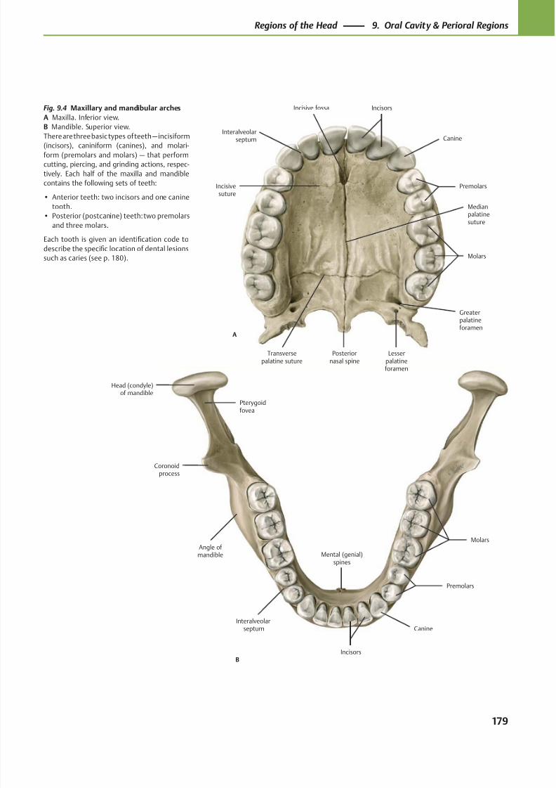
8/15/2019 Head and Neck Anatomy for Dental Medicine - Thieme; (January 26, 2010)
http://slidepdf.com/reader/full/head-and-neck-anatomy-for-dental-medicine-thieme-january-26-2010 192/384
B
Interalveolarseptum
Molars
Premolars
Canine
Incisors
Mental (genial)spines
Angle of mandible
Coronoidprocess
Head (condyle)of mandible
Pterygoid
fovea
A
Incisivesuture
Interalveolar
septum
Incisive fossa
Molars
Premolars
Canine
Incisors
Medianpalatinesuture
Greaterpalatineforamen
Lesserpalatineforamen
Posteriornasal spine
Transversepalatine suture
Fig. 9.4 Maxillary and mandibular arches
A Maxilla. Inferior view.
B Mandible. Superior view.
There are three basic types of teeth — incisiform(incisors), caniniform (canines), and molari-
form (premolars and molars) — that perform
cutting, piercing, and grinding actions, respec-
tively. Each half of the maxilla and mandible
contains the following sets of teeth:
• Anterior teeth: two incisors and one canine
tooth.
• Posterior (postcanine) teeth: two premolars
and three molars.
Each tooth is given an identification code to
describe the specific location of dental lesions
such as caries (see p. 180).
179
Regions of the Head 9. Oral Cavity & Perioral Regions
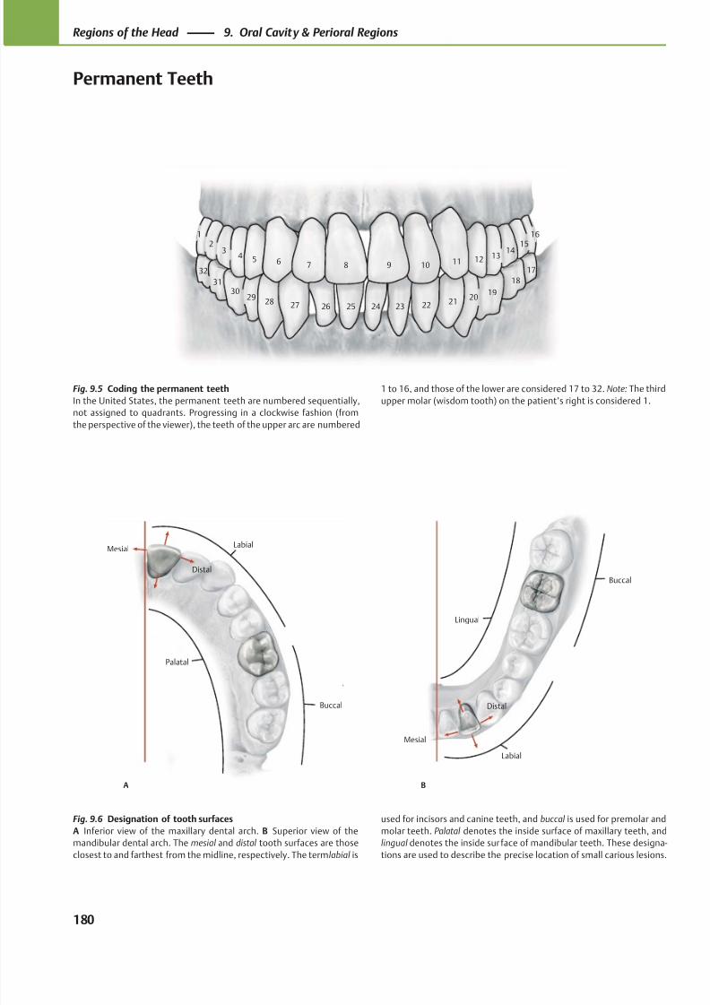
8/15/2019 Head and Neck Anatomy for Dental Medicine - Thieme; (January 26, 2010)
http://slidepdf.com/reader/full/head-and-neck-anatomy-for-dental-medicine-thieme-january-26-2010 193/384
3130
2928 27 26 25
18
1920
21222324
1514
131211109
23
4 5 6 7 8
1 16
32 17
LabialMesial
Palatal
Distal
Buccal Distal
Mesial
Lingual
Labial
Buccal
A B
Fig. 9.5 Coding the permanent teeth
In the United States, the permanent teeth are numbered sequentially,
not assigned to quadrants. Progressing in a clockwise fashion (from
the perspective of the viewer), the teeth of the upper arc are numbered
Fig. 9.6 Designation of tooth surfaces
A Inferior view of the maxillary dental arch. B Superior view of the
mandibular dental arch. The mesial and distal tooth surfaces are those
closest to and farthest from the midline, respectively. The term labial is
1 to 16, and those of the lower are considered 17 to 32. Note: The third
upper molar (wisdom tooth) on the patient’s right is considered 1.
used for incisors and canine teeth, and buccal is used for premolar and
molar teeth. Palatal denotes the inside surface of maxillary teeth, and
lingual denotes the inside sur face of mandibular teeth. These designa-
tions are used to describe the precise location of small carious lesions.
180
Regions of the Head 9. Oral Cavity & Perioral Regions
Permanent Teeth
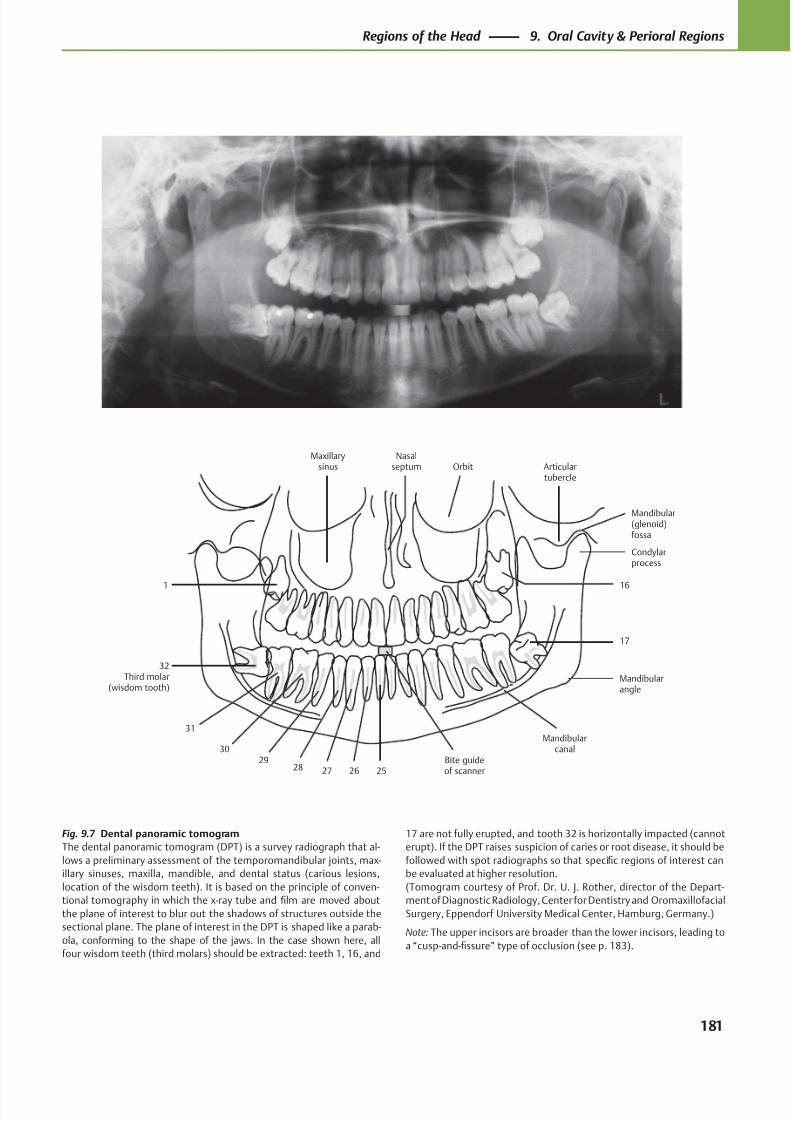
8/15/2019 Head and Neck Anatomy for Dental Medicine - Thieme; (January 26, 2010)
http://slidepdf.com/reader/full/head-and-neck-anatomy-for-dental-medicine-thieme-january-26-2010 194/384
Mandibularcanal
Articulartubercle
Nasalseptum
Maxillarysinus
Mandibularangle
Bite guideof scanner25
16
17
Condylarprocess
Mandibular(glenoid)fossa
Orbit
26272829
30
31
32Third molar
(wisdom tooth)
1
Fig. 9.7 Dental panoramic tomogram
The dental panoramic tomogram (DPT) is a survey radiograph that al-
lows a preliminary assessment of the temporomandibular joints, max-
illary sinuses, maxilla, mandible, and dental status (carious lesions,
location of the wisdom teeth). It is based on the principle of conven-
tional tomography in which the x-ray tube and film are moved about
the plane of interest to blur out the shadows of structures outside the
sectional plane. The plane of interest in the DPT is shaped like a parab-
ola, conforming to the shape of the jaws. In the case shown here, all
four wisdom teeth (third molars) should be extracted: teeth 1, 16, and
17 are not fully erupted, and tooth 32 is horizontally impacted (cannot
erupt). If the DPT raises suspicion of caries or root disease, it should be
followed with spot radiographs so that specific regions of interest can
be evaluated at higher resolution.
(Tomogram courtesy of Prof. Dr. U. J. Rother, director of the Depart-
ment of Diagnostic Radiology, Center for Dentistry and Oromaxillofacial
Surgery, Eppendorf University Medical Center, Hamburg, Germany.)
Note: The upper incisors are broader than the lower incisors, leading to
a “cusp-and-fissure” type of occlusion (see p. 183).
181
Regions of the Head 9. Oral Cavity & Perioral Regions
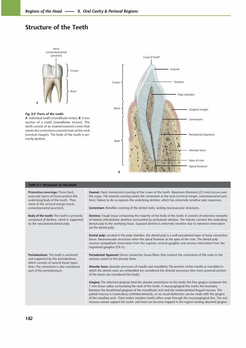
8/15/2019 Head and Neck Anatomy for Dental Medicine - Thieme; (January 26, 2010)
http://slidepdf.com/reader/full/head-and-neck-anatomy-for-dental-medicine-thieme-january-26-2010 195/384
Root
Neck(cementoenamel
junction)
Crown
A
Crown
Neck
Root
Enamel
Dentine
Pulp chamber
Gingival margin
Alveolar bone
Cementum
Apex of root
B
Cusp of tooth
Periodontal ligament
Apical foramen
Table 9.1 Structures of the tooth
Protective coverings: These hard,
avascular layers of tissue protect the
underlying body of the tooth. They
meet at the cervical margin (neck,
cementoenamel junction).
Enamel: Hard, translucent covering of the crown of the tooth. Maximum thickness (2.5 mm) occurs over
the cusps. The enamel covering meets the cementum at the neck (cervical margin, cementoenamel junc-
tion). Failure to do so exposes the underlying dentine, which has extremely sensitive pain responses.
Cementum: Bonelike covering of the dental roots, lacking neurovascular structures.
Body of the tooth: The tooth is primarily
composed of dentine, which is supported
by the vascularized dental pulp.
Dentine: Tough tissue composing the majority of the body of the tooth. It consists of extensive networks
of tubules (intratubular dentine) surrounded by peritubular dentine. The tubules connect the underlying
dental pulp to the overlying tissue. Exposed dentine is extremely sensitive due to extensive innervation
via the dental pulp.
Dental pulp: Located in the pulp chamber, the dental pulp is a well-vascularized layer of loose connective
tissue. Neurovascular structures enter the apical foramen at the apex of the root. The dental pulp
receives sympathetic innervation from the superior cervical ganglion and sensory innervation from thetrigeminal ganglion (CN V).
Periodontium: The tooth is anchored
and supported by the periodontium,
which consists of several tissue types.
Note: The cementum is also considered
part of the periodontium.
Periodontal ligament: Dense connective tissue fibers that connect the cementum of the roots in the
osseous socket to the alveolar bone.
Alveolar bone (alveolar processes of maxilla and mandible): The portion of the maxilla or mandible in
which the dental roots are embedded are considered the alveolar processes (the more proximal portion
of the bones are considered the body).
Gingiva: The attached gingivae bind the alveolar periosteum to the teeth; the free gingiva composes the
1 mm tissue radius surrounding the neck of the tooth. A mucosogingival line marks the boundary
between the keratinized gingivae of the mandibular arch and the nonkeratinized lingual mucosa. The
palatal mucosa is masticatory (orthokeratinized), so no visual distinction can be made with the gingiva
of the maxillary arch. Third molars (wisdom teeth) often erupt through the mucosogingival line. The oral
mucosa cannot support the tooth, and food can become trapped in the regions lacking attached gingiva.
Fig. 9.8 Parts of the tooth
A Individual tooth (mandibular molar). B Cross
section of a tooth (mandibular incisor). Theteeth consist of an enamel-covered crown that
meets the cementum-covered roots at the neck
(cervical margin). The body of the tooth is pri-
marily dentine.
182
Regions of the Head 9. Oral Cavity & Perioral Regions
Structure of the Teeth
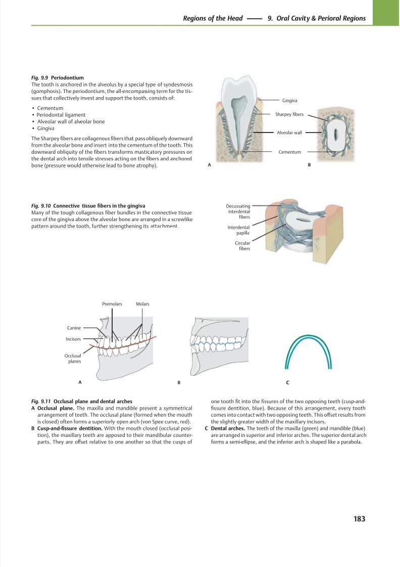
8/15/2019 Head and Neck Anatomy for Dental Medicine - Thieme; (January 26, 2010)
http://slidepdf.com/reader/full/head-and-neck-anatomy-for-dental-medicine-thieme-january-26-2010 196/384
Decussatinginterdental
fibers
Circularfibers
Interdentalpapilla
Gingiva
Alveolar wall
Sharpey fibers
Cementum
A B
A
Occlusalplanes
MolarsPremolars
Canine
Incisors
B C
Fig. 9.9 Periodontium
The tooth is anchored in the alveolus by a special type of syndesmosis
(gomphosis). The periodontium, the all-encompassing term for the tis -
sues that collectively invest and support the tooth, consists of:
• Cementum
• Periodontal ligament
• Alveolar wall of alveolar bone
• Gingiva
The Sharpey fibers are collagenous fibers that pass obliquely downward
from the alveolar bone and insert into the cementum of the tooth. This
downward obliquity of the fibers transforms masticatory pressures on
the dental arch into tensile stresses acting on the fibers and anchored
bone (pressure would otherwise lead to bone atrophy).
Fig. 9.10 Connective tissue fibers in the gingiva
Many of the tough collagenous fiber bundles in the connective tissue
core of the gingiva above the alveolar bone are arranged in a screwlike
pattern around the tooth, further strengthening its attachment.
Fig. 9.11 Occlusal plane and dental arches
A Occlusal plane. The maxilla and mandible present a symmetrical
arrangement of teeth. The occlusal plane (formed when the mouth
is closed) often forms a superiorly open arch (von Spee curve, red).
B Cusp-and-fissure dentition. With the mouth closed (occlusal posi-
tion), the maxillary teeth are apposed to their mandibular counter-
parts. They are off set relative to one another so that the cusps of
one tooth fit into the fissures of the two opposing teeth (cusp-and-
fissure dentition, blue). Because of this arrangement, every tooth
comes into contact with two opposing teeth. This off set results from
the slightly greater width of the maxillary incisors.
C Dental arches. The teeth of the maxilla (green) and mandible (blue)
are arranged in superior and inferior arches. The superior dental arch
forms a semi-ellipse, and the inferior arch is shaped like a parabola.
183
Regions of the Head 9. Oral Cavity & Perioral Regions
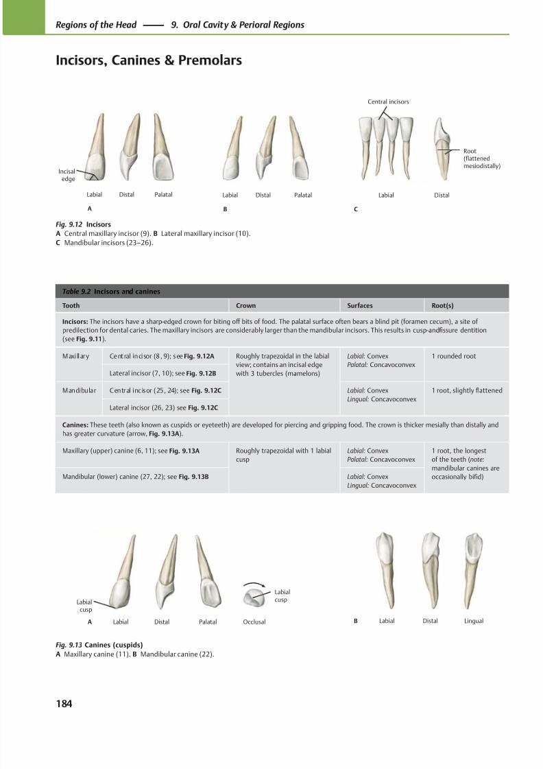
8/15/2019 Head and Neck Anatomy for Dental Medicine - Thieme; (January 26, 2010)
http://slidepdf.com/reader/full/head-and-neck-anatomy-for-dental-medicine-thieme-january-26-2010 197/384
PalatalDistalLabial
B
PalatalDistalLabial
A
Incisaledge
Labial Distal
C
Central incisors
Root(flattenedmesiodistally)
Labialcusp
PalatalDistalLabialA Occlusal
Labialcusp
LingualDistalLabialB
Table 9.2 Incisors and canines
Tooth Crown Surfaces Root(s)
Incisors: The incisors have a sharp-edged crown for biting off bits of food. The palatal surface often bears a blind pit (foramen cecum), a site of
predilection for dental caries. The maxillary incisors are considerably larger than the mandibular incisors. This results in cusp-and-fissure dentition
(see Fig. 9.11).
Maxi llary Central incisor (8, 9); see Fig. 9.12A Roughly trapezoidal in the labial
view; contains an incisal edge
with 3 tubercles (mamelons)
Labial: Convex
Palatal: Concavoconvex
1 rounded root
Lateral incisor (7, 10); see Fig. 9.12B
Mandibular Central incisor (25, 24); see Fig. 9.12C Labial: Convex
Lingual: Concavoconvex
1 root, slightly flattened
Lateral incisor (26, 23) see Fig. 9.12C
Canines: These teeth (also known as cuspids or eyeteeth) are developed for piercing and gripping food. The crown is thicker mesially than distally and
has greater curvature (arrow, Fig. 9.13A).
Maxillary (upper) canine (6, 11); see Fig. 9.13A Roughly trapezoidal with 1 labial
cusp
Labial: Convex
Palatal: Concavoconvex
1 root, the longest
of the teeth (note:
mandibular canines are
occasionally bifid)Mandibular (lower) canine (27, 22); see Fig. 9.13B Labial: Convex
Lingual: Concavoconvex
Fig. 9.12 Incisors
A Central maxillary incisor (9). B Lateral maxillary incisor (10).
C Mandibular incisors (23–26).
Fig. 9.13 Canines (cuspids)
A Maxillary canine (11). B Mandibular canine (22).
184
Regions of the Head 9. Oral Cavity & Perioral Regions
Incisors, Canines & Premolars
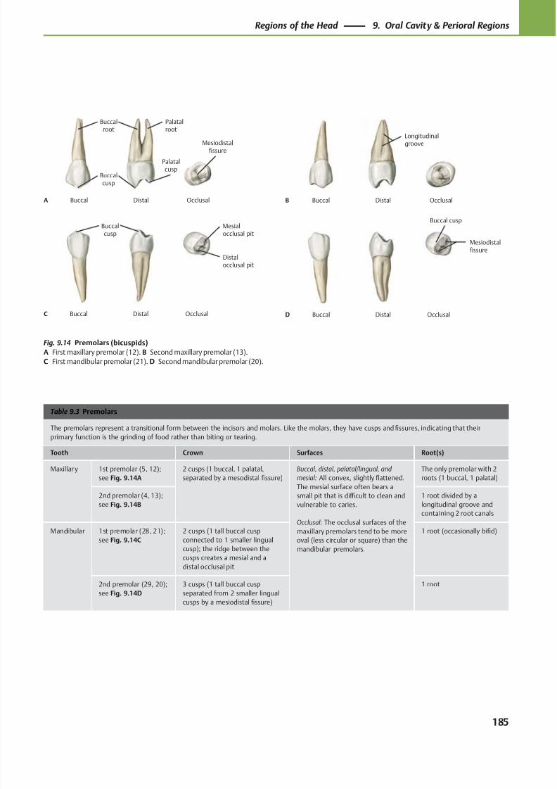
8/15/2019 Head and Neck Anatomy for Dental Medicine - Thieme; (January 26, 2010)
http://slidepdf.com/reader/full/head-and-neck-anatomy-for-dental-medicine-thieme-january-26-2010 198/384
Mesiodistalfissure
DistalBuccalA
Buccalroot
Buccalcusp
Palatalroot
Occlusal
Palatalcusp
Longitudinalgroove
DistalBuccalB Occlusal
Distalocclusal pit
DistalBuccalC
Buccalcusp
Mesialocclusal pit
Occlusal
Mesiodistalfissure
DistalBuccalD Occlusal
Buccal cusp
Table 9.3 Premolars
The premolars represent a transitional form between the incisors and molars. Like the molars, they have cusps and fissures, indicating that their
primary function is the grinding of food rather than biting or tearing.
Tooth Crown Surfaces Root(s)
Maxillary 1st premolar (5, 12);
see Fig. 9.14A
2 cusps (1 buccal, 1 palatal,
separated by a mesodistal fissure)
Buccal, distal, palatal/lingual, and
mesial: All convex, slightly flattened.
The mesial surface often bears a
small pit that is diffi cult to clean and
vulnerable to caries.
Occlusal: The occlusal surfaces of the
maxillary premolars tend to be more
oval (less circular or square) than the
mandibular premolars.
The only premolar with 2
roots (1 buccal, 1 palatal)
2nd premolar (4, 13);
see Fig. 9.14B
1 root divided by a
longitudinal groove and
containing 2 root canals
Mandibular 1st premolar (28, 21);
see Fig. 9.14C
2 cusps (1 tall buccal cusp
connected to 1 smaller lingual
cusp); the ridge between thecusps creates a mesial and a
distal occlusal pit
1 root (occasionally bifid)
2nd premolar (29, 20);
see Fig. 9.14D
3 cusps (1 tall buccal cusp
separated from 2 smaller lingual
cusps by a mesiodistal fissure)
1 root
Fig. 9.14 Premolars (bicuspids)
A First maxillary premolar (12). B Second maxillary premolar (13).
C First mandibular premolar (21). D Second mandibular premolar (20).
185
Regions of the Head 9. Oral Cavity & Perioral Regions
8/15/2019 Head and Neck Anatomy for Dental Medicine - Thieme; (January 26, 2010)
http://slidepdf.com/reader/full/head-and-neck-anatomy-for-dental-medicine-thieme-january-26-2010 199/384
Table 9.4 Molars
Most of the molars have three roots to withstand the greater masticatory pressures in the molar region. Because the molars crush and grind food,
they have a crown with a plateau. The fissures between the cusps are a frequent site of caries formation in adolescents. Note: The roots of the third
molars (wisdom teeth, which erupt after 16 years of age, if at all) are commonly fused together, particularly in the upper third molar. The mandibular
third molars erupt anterosuperiorly, and the maxillary third molars erupt posteroinferiorly. Impactions are therefore most common in mandibular
wisdom teeth.
Tooth Crown Surfaces Root(s)
Maxillar y 1st molar (3, 14);
see Fig. 9.15A
4 cusps (1 at each corner of its occlusal
surface); a ridge connects the
mesiopalatal and distobuccal cusps
Buccal, distal, palatal/lingual,
and mesial: All convex,
slightly flattened.
Occlusal: Rhomboid
3 roots (2 buccal and 1 palatal)
2nd molar (2, 15);
see Fig. 9.16A
4 cusps (though the distopalatal cusp is
often small or absent)
3 roots (2 buccal and 1 palatal),
occasionally fused
3rd molar (wisdom
tooth, 1, 16); see
Fig. 9.17A
3 cusps (no distopalatal) 3 roots (2 buccal and 1 palatal),
often fused
Mandibular 1st molar (30, 19);
see Fig. 9.15B
5 cusps (3 buccal and 2 lingual), all of
which are separated by fissures
Buccal, distal, palatal/lingual,
and mesial: All convex,
slightly flattened.
Occlusal: Rectangular
2 roots (1 mesial and 1 distal);
widely spaced
2nd molar (31, 18);
see Fig. 9.16B
4 cusps (2 buccal and 2 lingual) 2 roots (1 mesial and 1 distal)
3rd molar (wisdom
tooth, 32, 17); see
Fig. 9.17B
May resemble either the 1st or 2nd
molar
2 roots, often fused
186
Regions of the Head 9. Oral Cavity & Perioral Regions
Molars
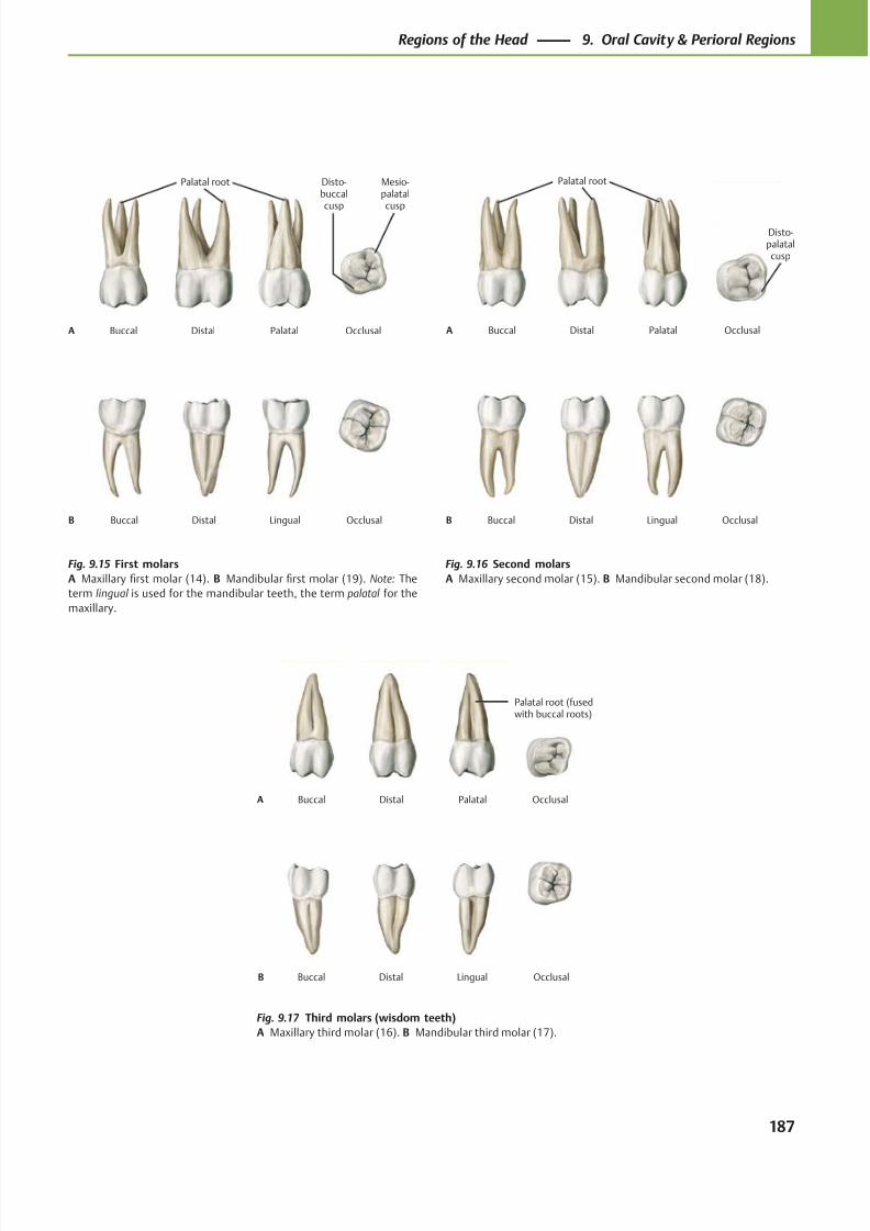
8/15/2019 Head and Neck Anatomy for Dental Medicine - Thieme; (January 26, 2010)
http://slidepdf.com/reader/full/head-and-neck-anatomy-for-dental-medicine-thieme-january-26-2010 200/384
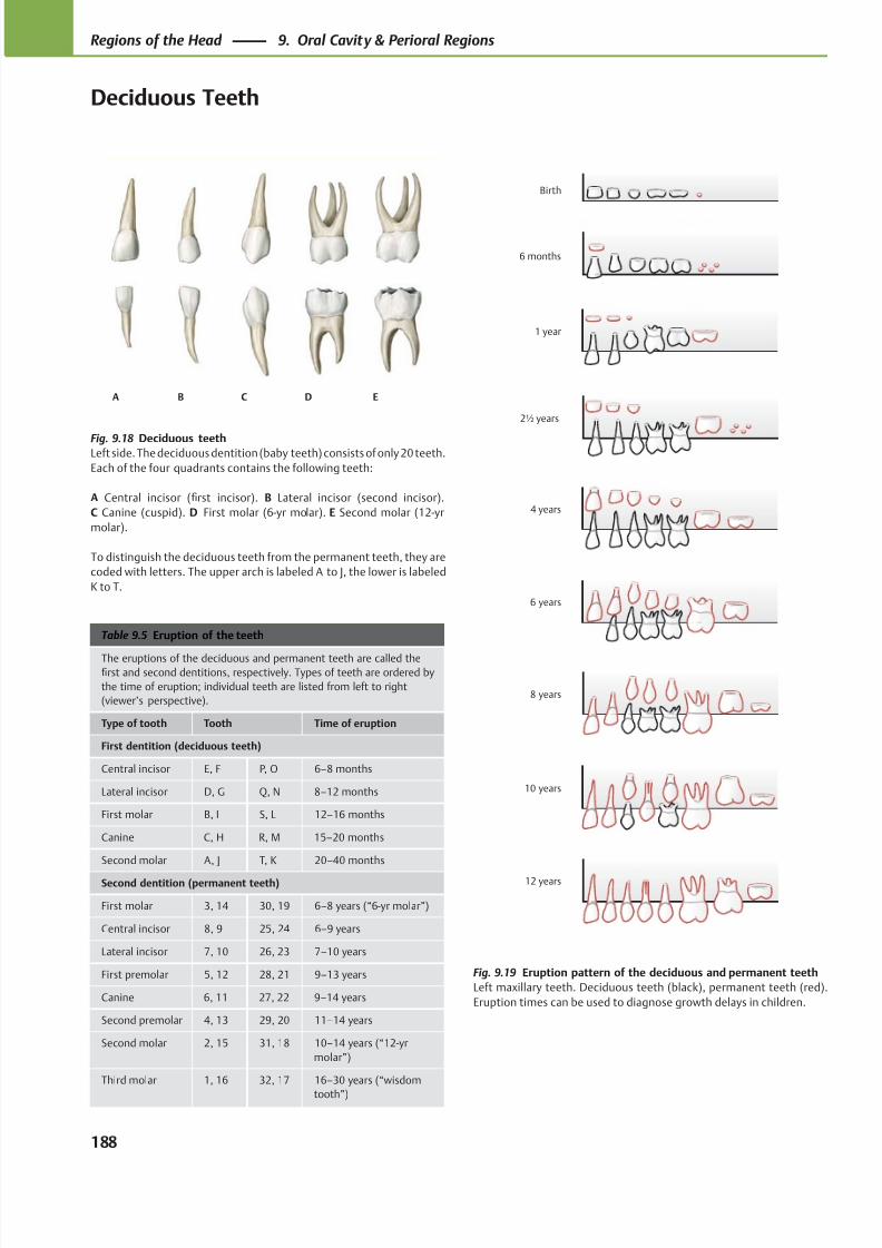
8/15/2019 Head and Neck Anatomy for Dental Medicine - Thieme; (January 26, 2010)
http://slidepdf.com/reader/full/head-and-neck-anatomy-for-dental-medicine-thieme-january-26-2010 201/384
A B C D E
12 years
10 years
8 years
6 years
4 years
2½ years
1 year
6 months
Birth
Table 9.5 Eruption of the teeth
The eruptions of the deciduous and permanent teeth are called thefirst and second dentitions, respectively. Types of teeth are ordered by
the time of eruption; individual teeth are listed from left to right
(viewer’s perspective).
Type of tooth Tooth Time of eruption
First dentition (deciduous teeth)
Central incisor E, F P, O 6–8 months
Lateral incisor D, G Q, N 8–12 months
First molar B, I S, L 12–16 months
Canine C, H R, M 15–20 months
Second molar A, J T, K 20–40 months
Second dentition (permanent teeth)
First molar 3, 14 30, 19 6–8 years (“6-yr molar”)
Central incisor 8, 9 25, 24 6–9 years
Lateral incisor 7, 10 26, 23 7–10 years
First premolar 5, 12 28, 21 9–13 years
Canine 6, 11 27, 22 9–14 years
Second premolar 4, 13 29, 20 11–14 years
Second molar 2, 15 31, 18 10–14 years (“12-yr
molar”)
Third molar 1, 16 32, 17 16–30 years (“wisdom
tooth”)
Fig. 9.18 Deciduous teethLeft side. The deciduous dentition (baby teeth) consists of only 20 teeth.
Each of the four quadrants contains the following teeth:
A Central incisor (first incisor). B Lateral incisor (second incisor).
C Canine (cuspid). D First molar (6-yr molar). E Second molar (12-yr
molar).
To distinguish the deciduous teeth from the permanent teeth, they are
coded with letters. The upper arch is labeled A to J, the lower is labeled
K to T.
Fig. 9.19 Eruption pattern of the deciduous and permanent teeth
Left maxillary teeth. Deciduous teeth (black), permanent teeth (red).
Eruption times can be used to diagnose growth delays in children.
188
Regions of the Head 9. Oral Cavity & Perioral Regions
Deciduous Teeth
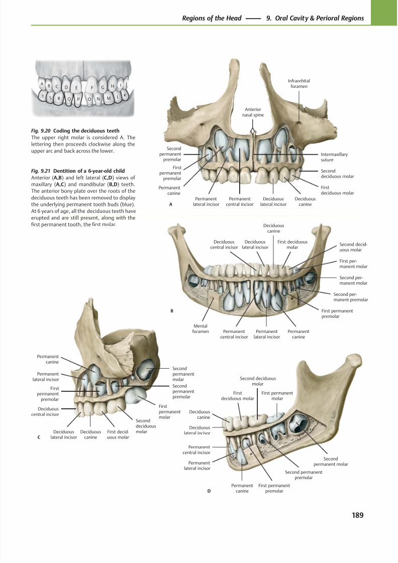
8/15/2019 Head and Neck Anatomy for Dental Medicine - Thieme; (January 26, 2010)
http://slidepdf.com/reader/full/head-and-neck-anatomy-for-dental-medicine-thieme-january-26-2010 202/384
Infraorbitalforamen
Anteriornasal spine
Intermaxillarysuture
Seconddeciduous molar
Firstdeciduous molar
Deciduouscanine
Deciduouslateral incisor
Permanentcentral incisor
Secondpermanent
premolar
Firstpermanent
premolar
Permanentcanine
Permanentlateral incisorA
Second deciduousmolar
Firstdeciduous molar
Deciduouscanine
Deciduouslateral incisor
Secondpermanent molar
First permanentmolar
Second permanentpremolar
First permanent
premolar
Permanent
canine
Permanentlateral incisor
Permanentcentral incisor
D
First per-manent molar
Second decid-uous molar
First deciduousmolar
Deciduouscanine
Deciduouslateral incisor
Deciduouscentral incisor
Second per-manent molar
Second per-manent premolar
Mentalforamen
First permanentpremolar
Permanentcanine
Permanentlateral incisor
Permanentcentral incisor
B
E F G H I JDCBA
O N M LK
PQRST
SeconddeciduousmolarFirst decid-
uous molarDeciduous
canineDeciduous
lateral incisor
Deciduouscentral incisor
Secondpermanentmolar
Firstpermanentmolar
Secondpermanentpremolar
First
permanentpremolar
Permanentcanine
Permanentlateral incisor
C
Fig. 9.21 Dentition of a 6-year-old child
Anterior (A,B) and left lateral (C,D) views of
maxillary (A,C) and mandibular (B,D) teeth.
The anterior bony plate over the roots of the
deciduous teeth has been removed to displaythe underlying permanent tooth buds (blue).
At 6 years of age, all the deciduous teeth have
erupted and are still present, along with the
first permanent tooth, the first molar.
Fig. 9.20 Coding the deciduous teeth
The upper right molar is considered A. The
lettering then proceeds clockwise along the
upper arc and back across the lower.
189
Regions of the Head 9. Oral Cavity & Perioral Regions
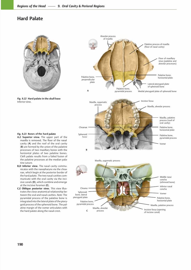
8/15/2019 Head and Neck Anatomy for Dental Medicine - Thieme; (January 26, 2010)
http://slidepdf.com/reader/full/head-and-neck-anatomy-for-dental-medicine-thieme-january-26-2010 203/384
Floor of maxillarysinus (palatine andalveolar processes)
Palatine bone,perpendicular
plate
Palatine bone,horizontal plate
Palatine process of maxilla
(floor of nasal cavity)
A
Alveolar processof maxilla
Lateral pterygoid plateof sphenoid bone
Medial pterygoid plate of sphenoid bonePalatine bone,
pyramidal process
Vomer
Sphenoidbone
Palatine bone,horizontal plate
Maxilla, palatineprocess (roof of oral cavity)
Choanae
B
Maxilla, zygomaticprocess
Maxilla, alveolar process
Palatine bone,pyramidal process
Incisive fossa
Choana
Middle nasalconcha(ethmoid bone)
VomerSphenoid
bone, lateralpterygoid plate Palatine bone,
horizontal plate
Maxilla, palatine process
Palatine bone,pyramidal process
C
Maxilla, zygomatic process
Maxilla, alveolarprocess
Inferior nasal
concha
Incisive fossa (openingof incisive canal)
Fig. 9.22 Hard palate in the skull base
Inferior view.
Fig. 9.23 Bones of the hard palate
A,C Superior view. The upper part of the
cavity (A) and the roof of the oral cavity
(B) are formed by the union of the palatine
processes of two maxillary bones with the
horizontal plates of two palatine bones.
Cleft palate results from a failed fusion of
the palatine processes at the median pala-
tine suture.
B,D Inferior view. The nasal cavity commu-
nicates with the nasopharynx via the choa-
nae, which begin at the posterior border of
the hard palate. The two nasal cavities com-
municate with the oral cavity via the inci-
sive canals (D), which combine and emerge
at the incisive foramen (E).
C,E Oblique posterior view. This view illus-trates the close anatomical relationship be-
tween the oral and nasal cavities. Note: The
pyramidal process of the palatine bone is
integrated into the lateral plate of the ptery-
goid process of the sphenoid bone. The pal-
atine margin of the vomer articulates with
the hard palate along the nasal crest.
190
Regions of the Head 9. Oral Cavity & Perioral Regions
Hard Palate
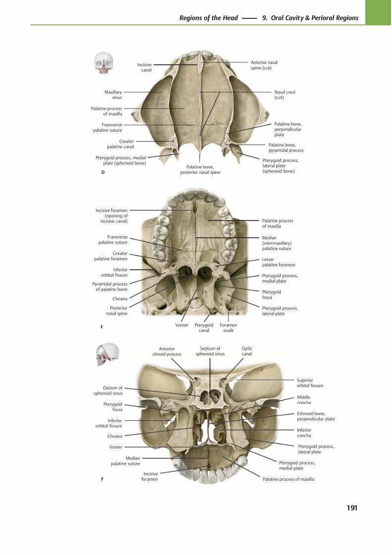
8/15/2019 Head and Neck Anatomy for Dental Medicine - Thieme; (January 26, 2010)
http://slidepdf.com/reader/full/head-and-neck-anatomy-for-dental-medicine-thieme-january-26-2010 204/384
Greaterpalatine canal Palatine bone,
pyramidal process
Pterygoid process,lateral plate(sphenoid bone)
Pterygoid process, medialplate (sphenoid bone)
Palatine bone,perpendicularplate
Palatine bone,posterior nasal spine
Transversepalatine suture
Palatine processof maxilla
Maxillary
sinus
Nasal crest
(cut)
Anterior nasalspine (cut)
Incisivecanal
D
Incisive foramen(opening of
incisive canal)
Inferiororbital fissure
Choana
Posteriornasal spine
Vomer
Pterygoidfossa
Foramenovale
Pterygoid process,lateral plate
Pterygoid process,medial plate
Pyramidal process
of palatine bone
Lesserpalatine foramen
Greaterpalatine foramen
Palatine processof maxilla
Median(intermaxillary)palatine suture
E
Transversepalatine suture
Pterygoidcanal
Septum of sphenoid sinus
Opticcanal
Anteriorclinoid process
Superiororbital fissure
Inferiororbital fissure
Choana
Medianpalatine suture
Incisiveforamen Palatine process of maxilla
Pterygoid process,medial plate
Pterygoid process,lateral plate
Pterygoidfossa
Inferiorconcha
Ethmoid bone,perpendicular plate
Middleconcha
Ostium of sphenoid sinus
F
Vomer
191
Regions of the Head 9. Oral Cavity & Perioral Regions
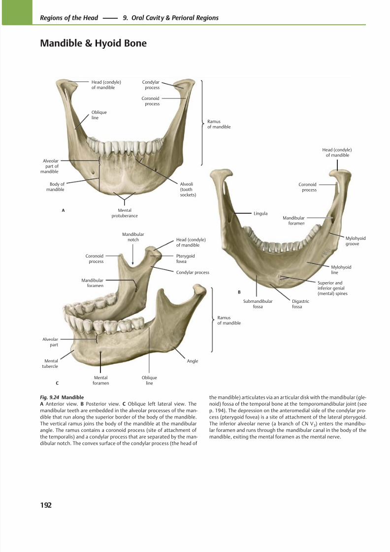
8/15/2019 Head and Neck Anatomy for Dental Medicine - Thieme; (January 26, 2010)
http://slidepdf.com/reader/full/head-and-neck-anatomy-for-dental-medicine-thieme-january-26-2010 205/384
Ramusof mandible
Obliqueline
Alveoli(tooth
sockets)
Mentalprotuberance
Body of mandible
Alveolarpart of
mandible
Coronoidprocess
Head (condyle)of mandible
A
Condylarprocess
Mylohyoidline
Mandibularforamen
Coronoidprocess
Head (condyle)of mandible
B
Lingula
Submandibularfossa
Superior and
inferior genial(mental) spines
Digastricfossa
Mylohyoidgroove
C
Angle
Obliqueline
Mentalforamen
Alveolarpart
Mentaltubercle
Mandibularforamen
Mandibularnotch
Coronoidprocess
Ramusof mandible
Pterygoidfovea
Head (condyle)of mandible
Condylar process
Fig. 9.24 Mandible
A Anterior view. B Posterior view. C Oblique left lateral view. The
mandibular teeth are embedded in the alveolar processes of the man-
dible that run along the superior border of the body of the mandible.
The vertical ramus joins the body of the mandible at the mandibular
angle. The ramus contains a coronoid process (site of attachment of
the temporalis) and a condylar process that are separated by the man-
dibular notch. The convex surface of the condylar process (the head of
the mandible) articulates via an articular disk with the mandibular (gle-
noid) fossa of the temporal bone at the temporomandibular joint (see
p. 194). The depression on the anteromedial side of the condylar pro-
cess (pterygoid fovea) is a site of attachment of the lateral pterygoid.
The inferior alveolar nerve (a branch of CN V 3) enters the mandibu-
lar foramen and runs through the mandibular canal in the body of the
mandible, exiting the mental foramen as the mental nerve.
192
Regions of the Head 9. Oral Cavity & Perioral Regions
Mandible & Hyoid Bone
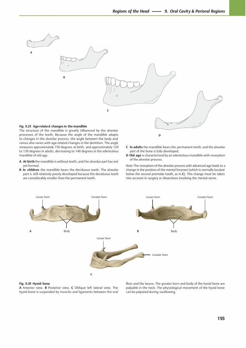
8/15/2019 Head and Neck Anatomy for Dental Medicine - Thieme; (January 26, 2010)
http://slidepdf.com/reader/full/head-and-neck-anatomy-for-dental-medicine-thieme-january-26-2010 206/384
B
C
D
A
Greater hornLesser horn
BodyA
Greater hornLesser horn
BodyB
Greater horn
Lesser horn
C
Fig. 9.25 Age-related changes in the mandible
The structure of the mandible is greatly influenced by the alveolar
processes of the teeth. Because the angle of the mandible adapts
to changes in the alveolar process, the angle between the body and
ramus also varies with age-related changes in the dentition. The angle
measures approximately 150 degrees at birth, and approximately 120
to 130 degrees in adults, decreasing to 140 degrees in the edentulous
mandible of old age.
A At birth the mandible is without teeth, and the alveolar part has not
yet formed.
B In children the mandible bears the deciduous teeth. The alveolar
part is still relatively poorly developed because the deciduous teeth
are considerably smaller than the permanent teeth.
C In adults the mandible bears the permanent teeth, and the alveolar
part of the bone is fully developed.
D Old age is characterized by an edentulous mandible with resorption
of the alveolar process.
Note: The resorption of the alveolar process with advanced age leads to a
change in the position of the mental foramen (which is normally located
below the second premolar tooth, as in C). This change must be taken
into account in surgery or dissections involving the mental nerve.
Fig. 9.26 Hyoid bone
A Anterior view. B Posterior view. C Oblique left lateral view. The
hyoid bone is suspended by muscles and ligaments between the oral
floor and the larynx. The greater horn and body of the hyoid bone are
palpable in the neck. The physiological movement of the hyoid bone
can be palpated during swallowing.
193
Regions of the Head 9. Oral Cavity & Perioral Regions
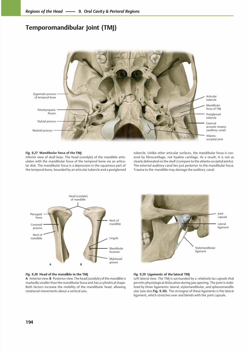
8/15/2019 Head and Neck Anatomy for Dental Medicine - Thieme; (January 26, 2010)
http://slidepdf.com/reader/full/head-and-neck-anatomy-for-dental-medicine-thieme-january-26-2010 207/384
Petrotympanicfissure
Articulartubercle
Mandibularfossa of TMJ
Externalacoustic meatus(auditory canal)
Zygomatic processof temporal bone
Styloid process
Mastoid process
Postglenoidtubercle
Atlanto-occipital joint
Stylomandibularligament
Jointcapsule
Lateralligament
Mylohyoidgroove
Mandibularforamen
Lingula
Neck ofmandible
Neck of mandible
Coronoidprocess
Pterygoidfovea
Head (condyle)of mandible
A B
Fig. 9.27 Mandibular fossa of the TMJ
Inferior view of skull base. The head (condyle) of the mandible artic-
ulates with the mandibular fossa of the temporal bone via an articu-
lar disk. The mandibular fossa is a depression in the squamous part of
the temporal bone, bounded by an articular tubercle and a postglenoid
Fig. 9.28 Head of the mandible in the TMJ
A Anterior view.B Posterior view. The head (condyle) of the mandible is
markedly smaller than the mandibular fossa and has a cylindrical shape.
Both factors increase the mobility of the mandibular head, allowing
rotational movements about a vertical axis.
Fig. 9.29 Ligaments of the lateral TMJ
Left lateral view. The TMJ is surrounded by a relatively lax capsule that
permits physiological dislocation during jaw opening. The joint is stabi-
lized by three ligaments: lateral, stylomandibular, and sphenomandib-
ular (see also Fig. 9.30). The strongest of these ligaments is the lateral
ligament, which stretches over and blends with the joint capsule.
tubercle. Unlike other articular surfaces, the mandibular fossa is cov-
ered by fibrocartilage, not hyaline cartilage. As a result, it is not as
clearly delineated on the skull (compare to the atlanto-occipital joints).
The external auditory canal lies just posterior to the mandibular fossa.
Trauma to the mandible may damage the auditory canal.
194
Regions of the Head 9. Oral Cavity & Perioral Regions
Temporomandibular Joint (TMJ)
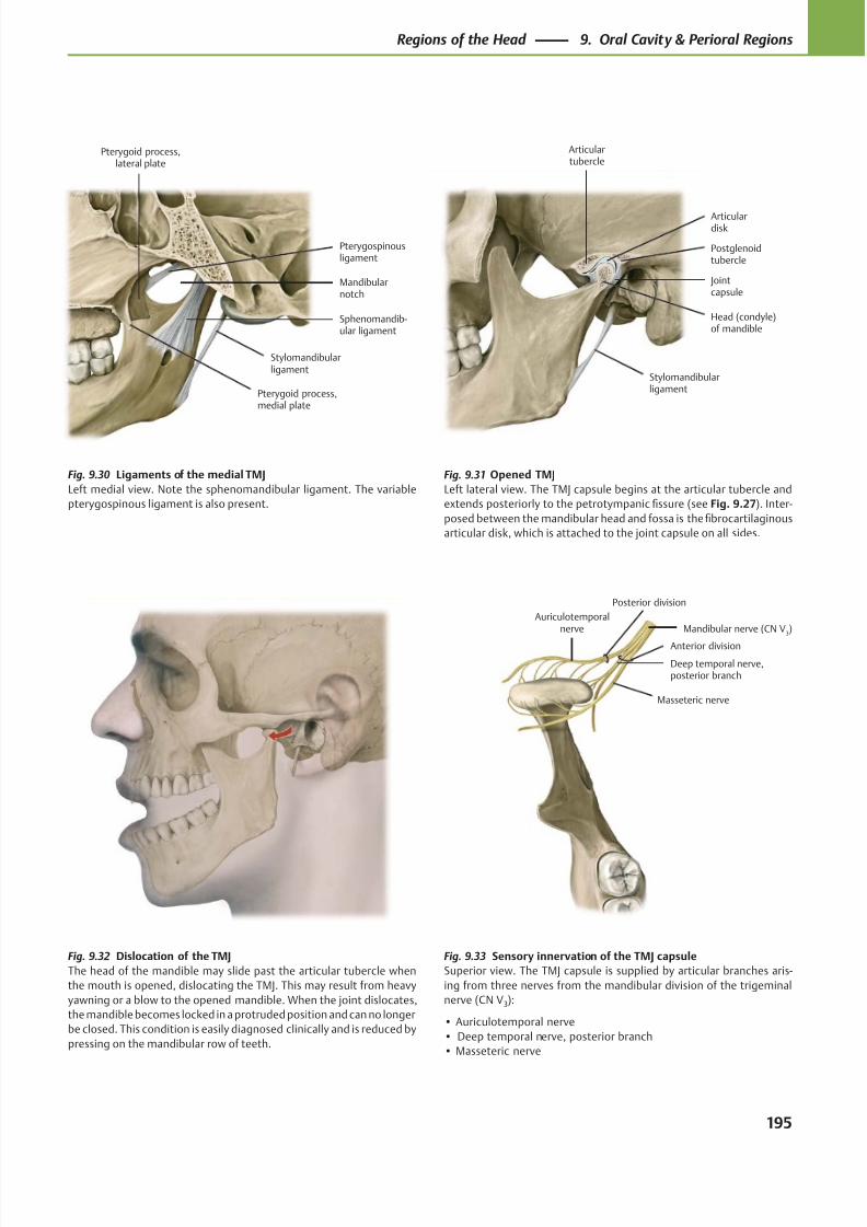
8/15/2019 Head and Neck Anatomy for Dental Medicine - Thieme; (January 26, 2010)
http://slidepdf.com/reader/full/head-and-neck-anatomy-for-dental-medicine-thieme-january-26-2010 208/384
Pterygoid process,medial plate
Pterygoid process,lateral plate
Stylomandibularligament
Sphenomandib-ular ligament
Mandibularnotch
Pterygospinousligament
Jointcapsule
Stylomandibularligament
Head (condyle)of mandible
Articulardisk
Articulartubercle
Postglenoidtubercle
Mandibular nerve (CN V3)
Masseteric nerve
Deep temporal nerve,posterior branch
Auriculotemporalnerve
Posterior division
Anterior division
Fig. 9.33 Sensory innervation of the TMJ capsule
Superior view. The TMJ capsule is supplied by articular branches aris-
ing from three nerves from the mandibular division of the trigeminal
nerve (CN V3):
• Auriculotemporal nerve
• Deep temporal nerve, posterior branch
• Masseteric nerve
Fig. 9.30 Ligaments of the medial TMJ
Left medial view. Note the sphenomandibular ligament. The variable
pterygospinous ligament is also present.
Fig. 9.31 Opened TMJ
Left lateral view. The TMJ capsule begins at the articular tubercle and
extends posteriorly to the petrotympanic fissure (see Fig. 9.27). Inter-
posed between the mandibular head and fossa is the fibrocartilaginous
articular disk, which is attached to the joint capsule on all sides.
Fig. 9.32 Dislocation of the TMJ
The head of the mandible may slide past the articular tubercle when
the mouth is opened, dislocating the TMJ. This may result from heavy
yawning or a blow to the opened mandible. When the joint dislocates,
the mandible becomes locked in a protruded position and can no longer
be closed. This condition is easily diagnosed clinically and is reduced by
pressing on the mandibular row of teeth.
195
Regions of the Head 9. Oral Cavity & Perioral Regions
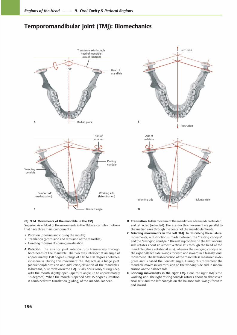
8/15/2019 Head and Neck Anatomy for Dental Medicine - Thieme; (January 26, 2010)
http://slidepdf.com/reader/full/head-and-neck-anatomy-for-dental-medicine-thieme-january-26-2010 209/384
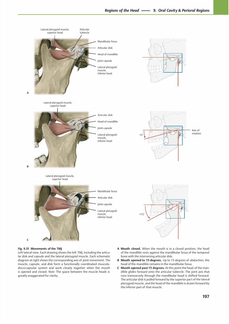
8/15/2019 Head and Neck Anatomy for Dental Medicine - Thieme; (January 26, 2010)
http://slidepdf.com/reader/full/head-and-neck-anatomy-for-dental-medicine-thieme-january-26-2010 210/384
Lateral pterygoidmuscle,inferior head
Head of mandible
Joint capsule
Articular disk
Articulartubercle
Lateral pterygoid muscle,superior head
A
Mandibular fossa
Lateral pterygoidmuscle,inferior head
Joint capsule
Head of mandible
Lateral pterygoid muscle,superior head
B
Articular disk
Axis ofrotation
15°
Lateral pterygoidmuscle,inferior head
Joint capsule
Articular disk
Lateral pterygoid muscle,superior head
C
Mandibular fossa
>15°
Fig. 9.35 Movements of the TMJ
Left lateral view. Each drawing shows the left TMJ, including the articu-
lar disk and capsule and the lateral pterygoid muscle. Each schematic
diagram at right shows the corresponding axis of joint movement. The
muscle, capsule, and disk form a functionally coordinated musculo-
disco-capsular system and work closely together when the mouth
is opened and closed. Note: The space between the muscle heads is
greatly exaggerated for clarity.
A Mouth closed. When the mouth is in a closed position, the head
of the mandible rests against the mandibular fossa of the temporal
bone with the intervening articular disk.
B Mouth opened to 15 degrees. Up to 15 degrees of abduction, the
head of the mandible remains in the mandibular fossa.
C Mouth opened past 15 degrees. At this point the head of the man-
dible glides forward onto the articular tubercle. The joint axis that
runs transversely through the mandibular head is shifted forward.
The articular disk is pulled forward by the superior part of the lateral
pterygoid muscle, and the head of the mandible is drawn forward bythe inferior part of that muscle.
197
Regions of the Head 9. Oral Cavity & Perioral Regions
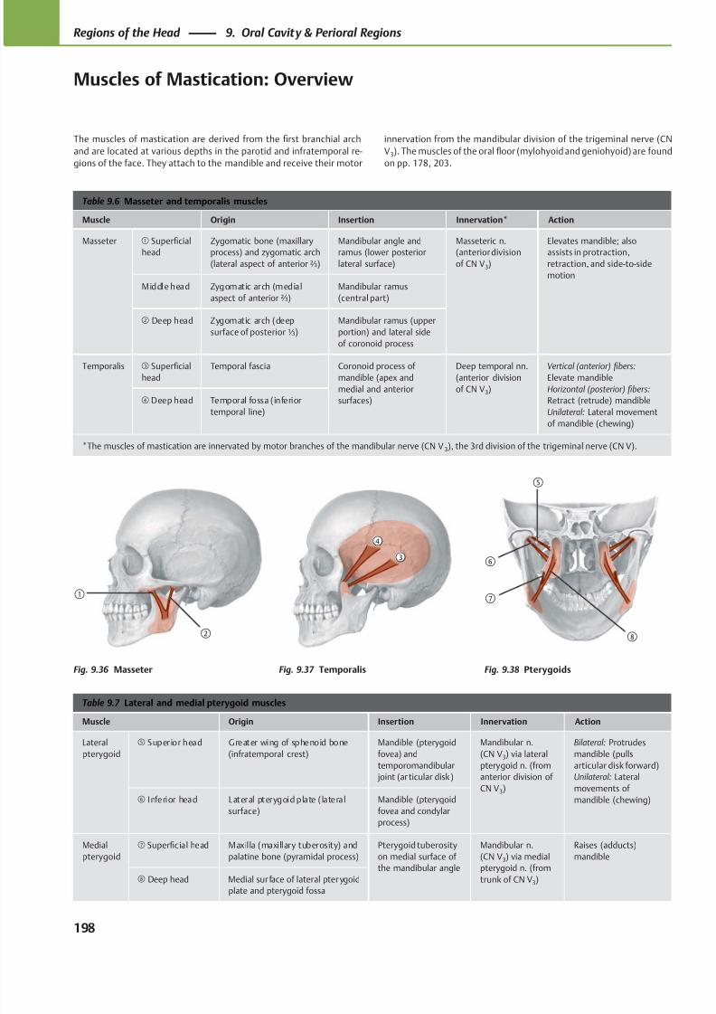
8/15/2019 Head and Neck Anatomy for Dental Medicine - Thieme; (January 26, 2010)
http://slidepdf.com/reader/full/head-and-neck-anatomy-for-dental-medicine-thieme-january-26-2010 211/384
①
②
④
③
⑧
⑤
⑥
⑦
Table 9.6 Masseter and temporalis muscles
Muscle Origin Insertion Innervation* Action
Masseter ① Superficial
head
Zygomatic bone (maxillary
process) and zygomatic arch
(lateral aspect of anterior ⅔)
Mandibular angle and
ramus (lower posterior
lateral surface)
Masseteric n.
(anterior division
of CN V3)
Elevates mandible; also
assists in protraction,
retraction, and side-to-side
motion
Middle head Zygomatic arch (medial
aspect of anterior ⅔)
Mandibular ramus
(central part)
② Deep head Zygomatic arch (deep
surface of posterior ⅓)
Mandibular ramus (upper
portion) and lateral side
of coronoid process
Temporalis ③ Superficial
head
Temporal fascia Coronoid process of
mandible (apex and
medial and anterior
surfaces)
Deep temporal nn.
(anterior division
of CN V3)
Vertical (anterior) fibers:
Elevate mandible
Horizontal (posterior) fibers:
Retract (retrude) mandible
Unilateral: Lateral movement
of mandible (chewing)
④ Deep head Temporal fossa (inferior
temporal line)
*The muscles of mastication are innervated by motor branches of the mandibular nerve (CN V 3), the 3rd division of the trigeminal nerve (CN V).
Table 9.7 Lateral and medial pterygoid muscles
Muscle Origin Insertion Innervation Action
Lateral
pterygoid
⑤ Superior head Greater wing of sphenoid bone
(infratemporal crest)
Mandible (pterygoid
fovea) and
temporomandibular
joint (ar ticular disk)
Mandibular n.
(CN V3) via lateral
pterygoid n. (from
anterior division of
CN V3)
Bilateral: Protrudes
mandible (pulls
articular disk forward)
Unilateral: Lateral
movements of
mandible (chewing)⑥ Inferior head Lateral pterygoid plate ( lateral
surface)
Mandible (pterygoid
fovea and condylar
process)
Medial
pterygoid
⑦ Superficial head Maxilla (maxillary tuberosity) and
palatine bone (pyramidal process)
Pterygoid tuberosity
on medial surface of
the mandibular angle
Mandibular n.
(CN V3) via medial
pterygoid n. (from
trunk of CN V3)
Raises (adducts)
mandible
⑧ Deep head Medial sur face of lateral pterygoid
plate and pterygoid fossa
The muscles of mastication are derived from the first branchial arch
and are located at various depths in the parotid and infratemporal re-
gions of the face. They attach to the mandible and receive their motor
Fig. 9.36 Masseter Fig. 9.37 Temporalis Fig. 9.38 Pterygoids
innervation from the mandibular division of the trigeminal nerve (CN
V3). The muscles of the oral floor (mylohyoid and geniohyoid) are found
on pp. 178, 203.
198
Regions of the Head 9. Oral Cavity & Perioral Regions
Muscles of Mastication: Overview
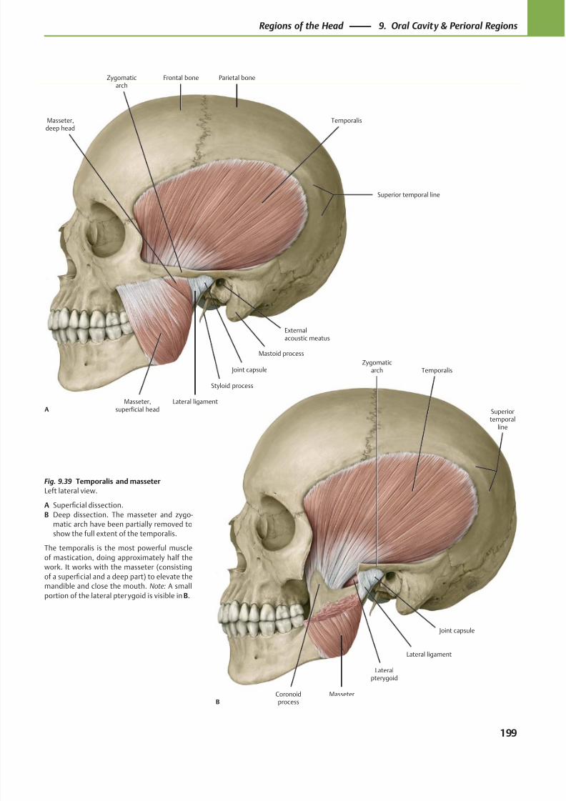
8/15/2019 Head and Neck Anatomy for Dental Medicine - Thieme; (January 26, 2010)
http://slidepdf.com/reader/full/head-and-neck-anatomy-for-dental-medicine-thieme-january-26-2010 212/384
Coronoid
process
Joint capsule
Lateralpterygoid
Masseter
Lateral ligament
Temporalis
B
Zygomaticarch
Superior
temporalline
Frontal bone Parietal boneZygomaticarch
Externalacoustic meatus
Mastoid process
Joint capsule
Lateral ligament
Styloid process
Masseter,deep head
Masseter,superficial head
Temporalis
A
Superior temporal line
Fig. 9.39 Temporalis and masseter
Left lateral view.
A Superficial dissection.
B Deep dissection. The masseter and zygo-
matic arch have been partially removed to
show the full extent of the temporalis.
The temporalis is the most powerful muscle
of mastication, doing approximately half thework. It works with the masseter (consisting
of a superficial and a deep part) to elevate the
mandible and close the mouth. Note: A small
portion of the lateral pterygoid is visible in B.
199
Regions of the Head 9. Oral Cavity & Perioral Regions
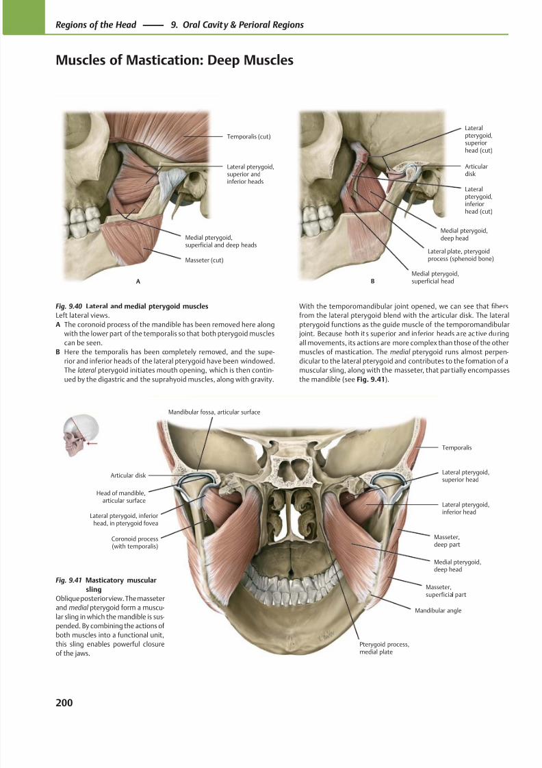
8/15/2019 Head and Neck Anatomy for Dental Medicine - Thieme; (January 26, 2010)
http://slidepdf.com/reader/full/head-and-neck-anatomy-for-dental-medicine-thieme-january-26-2010 213/384
Masseter (cut)
Medial pterygoid,superficial and deep heads
Lateral pterygoid,superior andinferior heads
Temporalis (cut)
A
Lateral plate, pterygoidprocess (sphenoid bone)
Medial pterygoid,deep head
Lateralpterygoid,inferiorhead (cut)
Articulardisk
Lateral
pterygoid,superiorhead (cut)
BMedial pterygoid,superficial head
Articular disk
Head of mandible,articular surface
Masseter,superficial part
Medial pterygoid,deep head
Masseter,deep part
Lateral pterygoid,inferior head
Lateral pterygoid,superior head
Temporalis
Mandibular angle
Pterygoid process,medial plate
Mandibular fossa, articular surface
Lateral pterygoid, inferiorhead, in pterygoid fovea
Coronoid process(with temporalis)
Fig. 9.40 Lateral and medial pterygoid muscles
Left lateral views.
A The coronoid process of the mandible has been removed here along
with the lower part of the temporalis so that both pterygoid muscles
can be seen.
B Here the temporalis has been completely removed, and the supe-
rior and inferior heads of the lateral pterygoid have been windowed.
The lateral pterygoid initiates mouth opening, which is then contin-
ued by the digastric and the suprahyoid muscles, along with gravity.
With the temporomandibular joint opened, we can see that fibers
from the lateral pterygoid blend with the articular disk. The lateral
pterygoid functions as the guide muscle of the temporomandibular
joint. Because both it s superior and inferior heads are ac tive during
all movements, its actions are more complex than those of the other
muscles of mastication. The medial pterygoid runs almost perpen-
dicular to the lateral pterygoid and contributes to the formation of a
muscular sling, along with the masseter, that partially encompasses
the mandible (see Fig. 9.41).
Fig. 9.41 Masticatory muscular
sling
Oblique posterior view. The masseter
and medial pterygoid form a muscu-
lar sling in which the mandible is sus-
pended. By combining the actions of
both muscles into a functional unit,
this sling enables powerful closure
of the jaws.
200
Regions of the Head 9. Oral Cavity & Perioral Regions
Muscles of Mastication: Deep Muscles
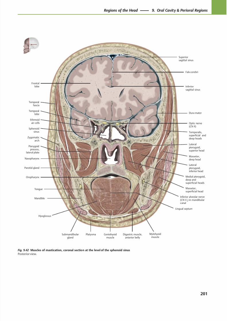
8/15/2019 Head and Neck Anatomy for Dental Medicine - Thieme; (January 26, 2010)
http://slidepdf.com/reader/full/head-and-neck-anatomy-for-dental-medicine-thieme-january-26-2010 214/384
Ethmoidair cells
Sphenoidsinus
Nasopharynx
Parotid gland
Oropharynx
Tongue
Submandibulargland
Mylohyoidmuscle
Digastric muscle,anterior belly
Platysma
Masseter,superficial head
Masseter,deep head
Lateral
pterygoid,inferior head
Temporalis,superficial anddeep heads
Lateralpterygoid,superior head
Medial pterygoid,deep andsuperficial heads
Superiorsagittal sinus
Dura materTemporallobe
Optic nerve(CN II)
Frontallobe
Falx cerebri
Mandible
Geniohyoidmuscle
Temporalfascia
Zygomaticarch
Pterygoidprocess,
lateral plate
Hyoglossus
Inferior alveolar nerve(CN V
3) in mandibular
canal
Lingual septum
Inferiorsagittal sinus
Fig. 9.42 Muscles of mastication, coronal section at the level of the sphenoid sinus
Posterior view.
201
Regions of the Head 9. Oral Cavity & Perioral Regions
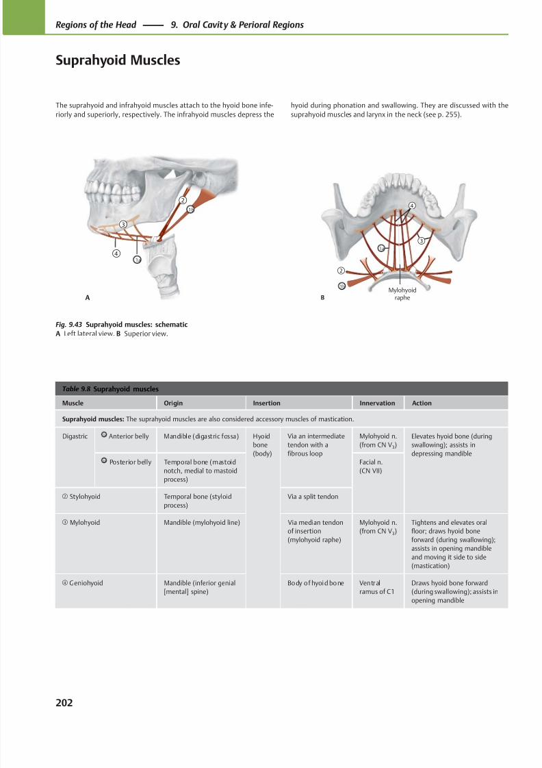
8/15/2019 Head and Neck Anatomy for Dental Medicine - Thieme; (January 26, 2010)
http://slidepdf.com/reader/full/head-and-neck-anatomy-for-dental-medicine-thieme-january-26-2010 215/384
Mylohyoidraphe
1b
1a
②
④
③
B
②
③
④
1b
1a
A
Table 9.8 Suprahyoid muscles
Muscle Origin Insertion Innervation Action
Suprahyoid muscles: The suprahyoid muscles are also considered accessory muscles of mastication.
Digastric 1a Anterior belly Mandible (digastric fossa) Hyoid
bone
(body)
Via an intermediate
tendon with a
fibrous loop
Mylohyoid n.
(from CN V3)
Elevates hyoid bone (during
swallowing); assists in
depressing mandible1b Posterior belly Temporal bone (mastoid
notch, medial to mastoid
process)
Facial n.
(CN VII)
② Stylohyoid Temporal bone (styloid
process)
Via a split tendon
③ Mylohyoid Mandible (mylohyoid line) Via median tendon
of insertion
(mylohyoid raphe)
Mylohyoid n.
(from CN V3)
Tightens and elevates oral
floor; draws hyoid bone
forward (during swallowing);assists in opening mandible
and moving it side to side
(mastication)
④ Geniohyoid Mandible (inferior genial
[mental] spine)
Body of hyoid bone Ventral
ramus of C1
Draws hyoid bone forward
(during swallowing); assists in
opening mandible
Fig. 9.43 Suprahyoid muscles: schematic
A Left lateral view. B Superior view.
The suprahyoid and infrahyoid muscles attach to the hyoid bone infe-
riorly and superiorly, respectively. The infrahyoid muscles depress the
hyoid during phonation and swallowing. They are discussed with the
suprahyoid muscles and larynx in the neck (see p. 255).
202
Regions of the Head 9. Oral Cavity & Perioral Regions
Suprahyoid Muscles
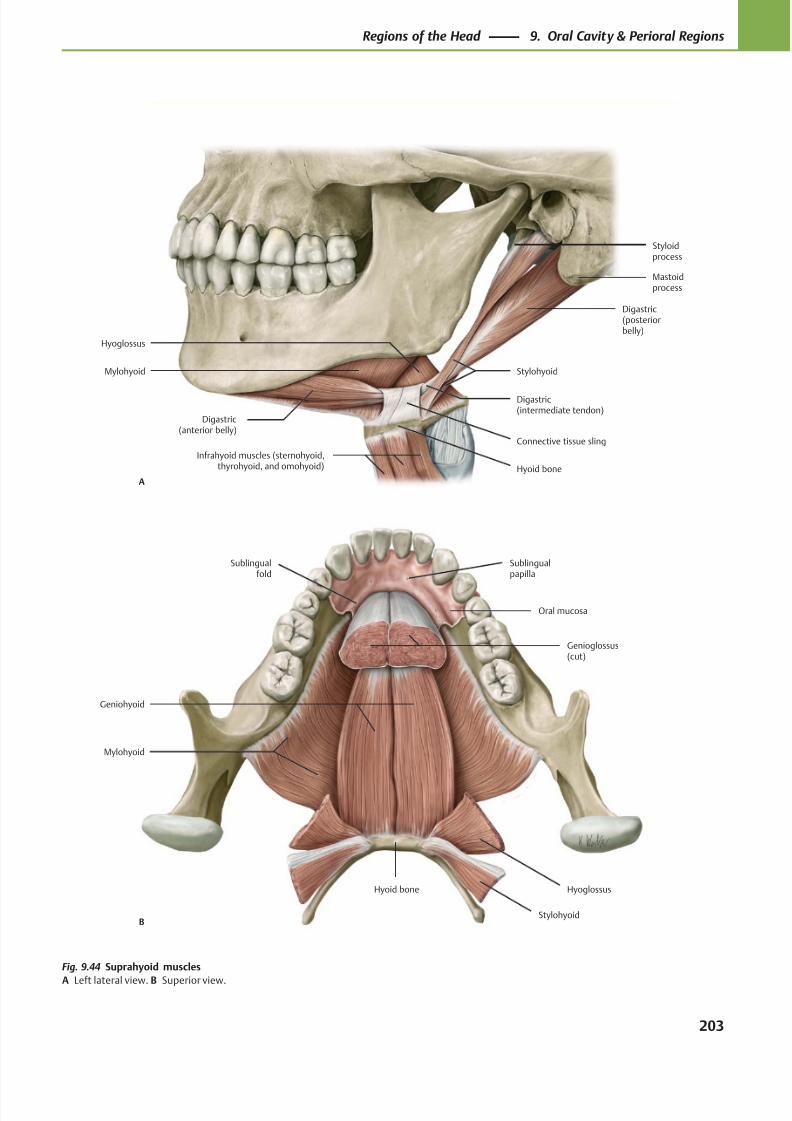
8/15/2019 Head and Neck Anatomy for Dental Medicine - Thieme; (January 26, 2010)
http://slidepdf.com/reader/full/head-and-neck-anatomy-for-dental-medicine-thieme-january-26-2010 216/384
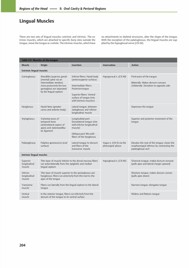
8/15/2019 Head and Neck Anatomy for Dental Medicine - Thieme; (January 26, 2010)
http://slidepdf.com/reader/full/head-and-neck-anatomy-for-dental-medicine-thieme-january-26-2010 217/384
Table 9.9 Muscles of the tongue
Muscle Origin Insertion Innervation Action
Extrinsic lingual muscles
Genioglossus Mandible (superior genial
[mental] spine via an
intermediate tendon);
more posteriorly the two
genioglossi are separated
by the lingual septum
Inferior fibers: Hyoid body
(anterosuperior surface)
Hypoglossal n. (CN XII) Protrusion of the tongue
Bilaterally: Makes dorsum concave
Unilaterally: Deviation to opposite sideIntermediate fibers:
Posterior tongue
Superior fibers: Ventralsurface of tongue (mix
with intrinsic muscles)
Hyoglossus Hyoid bone (greater
cornu and anterior body)
Lateral tongue, between
styloglossus and inferior
longitudinal muscle
Depresses the tongue
Styloglossus Styloid process of
temporal bone
(anterolateral aspect of
apex) and stylomandibu-
lar ligament
Longitudinal part:
Dorsolateral tongue (mix
with inferior longitudinal
muscle)
Superior and posterior movement of the
tongue
Oblique part: Mix with
fibers of the hyoglossus
Palatoglossus Palatine aponeurosis (oral
surface)
Lateral tongue to dorsum
and fibers of the
transverse muscle
Vagus n. (CN X) via the
pharyngeal plexus
Elevates the root of the tongue; closes the
oropharyngeal isthmus by contracting the
palatoglossal arch
Intrinsic lingual muscles
Superior
longitudinal
muscle
Thin layer of muscle inferior to the dorsal mucosa; fibers
run anterolaterally from the epiglottis and median
lingual septum
Hypoglossal n. (CN XII) Shortens tongue; makes dorsum concave
(pulls apex and lateral margin upward)
Inferior
longitudinal
muscle
Thin layer of muscle superior to the genioglossus and
hyoglossus; fibers run anteriorly from the root to the
apex of the tongue
Shortens tongue; makes dorsum convex
(pulls apex down)
Transverse
muscle
Fibers run laterally from the lingual septum to the lateral
tongue
Narrows tongue; elongates tongue
Vertical
muscle
In the anterior tongue, fibers run inferiorly from the
dorsum of the tongue to its ventral surface
Widens and flattens tongue
There are two sets of lingual muscles: extrinsic and intrinsic. The ex-
trinsic muscles, which are attached to specific bony sites outside the
tongue, move the tongue as a whole. The intrinsic muscles, which have
no attachments to skeletal structures, alter the shape of the tongue.
With the exception of the palatoglossus, the lingual muscles are sup-
plied by the hypoglossal nerve (CN XII).
204
Regions of the Head 9. Oral Cavity & Perioral Regions
Lingual Muscles
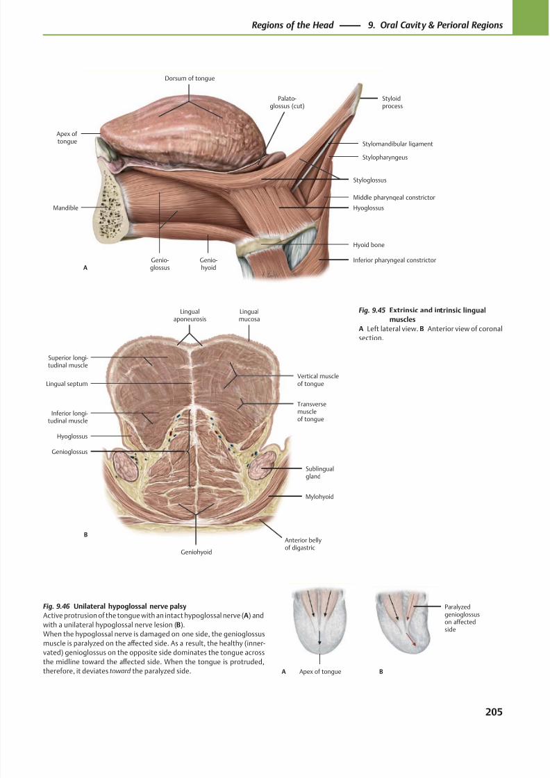
8/15/2019 Head and Neck Anatomy for Dental Medicine - Thieme; (January 26, 2010)
http://slidepdf.com/reader/full/head-and-neck-anatomy-for-dental-medicine-thieme-january-26-2010 218/384
Dorsum of tongue
Genio-glossus
Genio-hyoid
Hyoid bone
Hyoglossus
Styloglossus
Styloidprocess
Palato-glossus (cut)
A
Mandible
Apex of tongue Stylomandibular ligament
Stylopharyngeus
Middle pharyngeal constrictor
Inferior pharyngeal constrictor
Lingualaponeurosis
Superior longi-tudinal muscle
Inferior longi-tudinal muscle
Hyoglossus
Genioglossus
Geniohyoid
Mylohyoid
Sublingualgland
Transversemuscleof tongue
Vertical muscleof tongue
Lingualmucosa
B
Lingual septum
Anterior bellyof digastric
Apex of tongue
Paralyzedgenioglossuson affectedside
BA
Fig. 9.45 Extrinsic and intrinsic lingual
muscles
A Left lateral view. B Anterior view of coronal
section.
Fig. 9.46 Unilateral hypoglossal nerve palsy
Active protrusion of the tongue with an intact hypoglossal nerve (A) and
with a unilateral hypoglossal nerve lesion (B).
When the hypoglossal nerve is damaged on one side, the genioglossus
muscle is paralyzed on the aff ected side. As a result, the healthy (inner-
vated) genioglossus on the opposite side dominates the tongue across
the midline toward the aff ected side. When the tongue is protruded,
therefore, it deviates toward the paralyzed side.
205
Regions of the Head 9. Oral Cavity & Perioral Regions
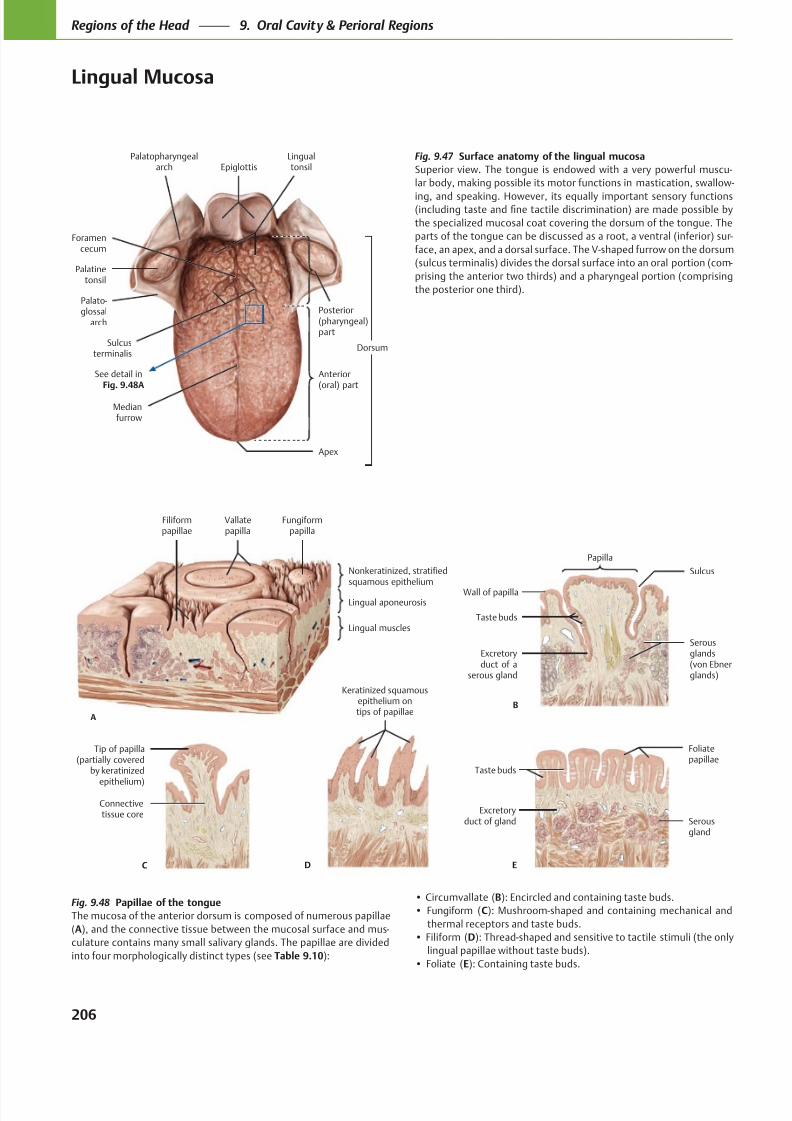
8/15/2019 Head and Neck Anatomy for Dental Medicine - Thieme; (January 26, 2010)
http://slidepdf.com/reader/full/head-and-neck-anatomy-for-dental-medicine-thieme-january-26-2010 219/384
Palatopharyngealarch
Palatinetonsil
Palato-glossal
arch
Lingualtonsil
Sulcusterminalis
Medianfurrow
Dorsum
Apex
Anterior(oral) part
Posterior(pharyngeal)part
Foramencecum
Epiglottis
See detail inFig. 9.48A
Vallatepapilla
Filiformpapillae
Lingual muscles
Lingual aponeurosis
Nonkeratinized, stratifiedsquamous epithelium
Fungiformpapilla
A
Sulcus
Papilla
Taste buds
Excretoryduct of a
serous gland
Wall of papilla
B
Serousglands(von Ebnerglands)
Connectivetissue core
Tip of papilla(partially covered
by keratinized
epithelium)
C
Keratinized squamousepithelium ontips of papillae
D
Serousgland
Excretoryduct of gland
Taste buds
Foliatepapillae
E
Fig. 9.47 Surface anatomy of the lingual mucosa
Superior view. The tongue is endowed with a very powerful muscu-
lar body, making possible its motor functions in mastication, swallow-
ing, and speaking. However, its equally important sensory functions
the specialized mucosal coat covering the dorsum of the tongue. The
-
face, an apex, and a dorsal surface. The V-shaped furrow on the dorsum
-
Fig. 9.48 Papillae of the tongue
The mucosa of the anterior dorsum is composed of numerous papillae
(A -
culature contains many small salivary glands. The papillae are divided
into four morphologically distinct types (see Table 9.10
B
C
thermal receptors and taste buds.
D
E
206
Regions of the Head 9. Oral Cavity & Perioral Regions
Lingual Mucosa
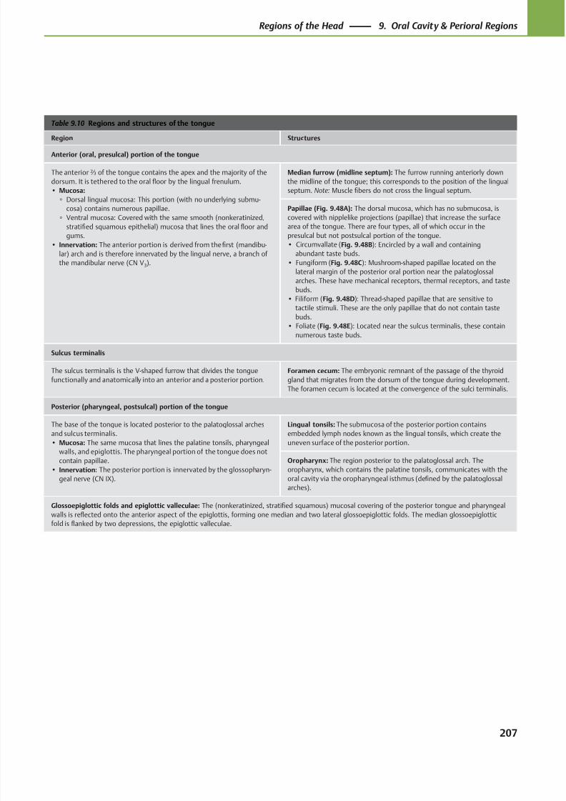
8/15/2019 Head and Neck Anatomy for Dental Medicine - Thieme; (January 26, 2010)
http://slidepdf.com/reader/full/head-and-neck-anatomy-for-dental-medicine-thieme-january-26-2010 220/384
Table 9.10 Regions and structures of the tongue
Region Structures
Anterior (oral, presulcal) portion of the tongue
The anterior ⅔ of the tongue contains the apex and the majority of the
dorsum. It is tethered to the oral floor by the lingual frenulum.
• Mucosa:
◦ Dorsal lingual mucosa: This portion (with no underlying submu-
cosa) contains numerous papillae.
◦ Ventral mucosa: Covered with the same smooth (nonkeratinized,
stratified squamous epithelial) mucosa that lines the oral floor and
gums.
• Innervation: The anterior portion is derived from the first (mandibu-
lar) arch and is therefore innervated by the lingual nerve, a branch of
the mandibular nerve (CN V3).
Median furrow (midline septum): The furrow running anteriorly down
the midline of the tongue; this corresponds to the position of the lingual
septum. Note: Muscle fibers do not cross the lingual septum.
Papillae (Fig. 9.48A): The dorsal mucosa, which has no submucosa, is
covered with nipplelike projections (papillae) that increase the surface
area of the tongue. There are four types, all of which occur in the
presulcal but not postsulcal portion of the tongue.
• Circumvallate (Fig. 9.48B): Encircled by a wall and containing
abundant taste buds.
• Fungiform (Fig. 9.48C): Mushroom-shaped papillae located on the
lateral margin of the posterior oral portion near the palatoglossal
arches. These have mechanical receptors, thermal receptors, and tastebuds.
• Filiform (Fig. 9.48D): Thread-shaped papillae that are sensitive to
tactile stimuli. These are the only papillae that do not contain taste
buds.
• Foliate (Fig. 9.48E): Located near the sulcus terminalis, these contain
numerous taste buds.
Sulcus terminalis
The sulcus terminalis is the V-shaped furrow that divides the tongue
functionally and anatomically into an anterior and a posterior portion.
Foramen cecum: The embryonic remnant of the passage of the thyroid
gland that migrates from the dorsum of the tongue during development.
The foramen cecum is located at the convergence of the sulci terminalis.
Posterior (pharyngeal, postsulcal) portion of the tongue
The base of the tongue is located posterior to the palatoglossal arches
and sulcus terminalis.
• Mucosa: The same mucosa that lines the palatine tonsils, pharyngeal
walls, and epiglottis. The pharyngeal portion of the tongue does not
contain papillae.
• Innervation: The posterior portion is innervated by the glossopharyn-
geal nerve (CN IX).
Lingual tonsils: The submucosa of the posterior portion contains
embedded lymph nodes known as the lingual tonsils, which create the
uneven surface of the posterior portion.
Oropharynx: The region posterior to the palatoglossal arch. The
oropharynx, which contains the palatine tonsils, communicates with the
oral cavity via the oropharyngeal isthmus (defined by the palatoglossal
arches).
Glossoepiglottic folds and epiglottic valleculae: The (nonkeratinized, stratified squamous) mucosal covering of the posterior tongue and pharyngeal
walls is reflected onto the anterior aspect of the epiglottis, forming one median and two lateral glossoepiglottic folds. The median glossoepiglottic
fold is flanked by two depressions, the epiglottic valleculae.
207
Regions of the Head 9. Oral Cavity & Perioral Regions
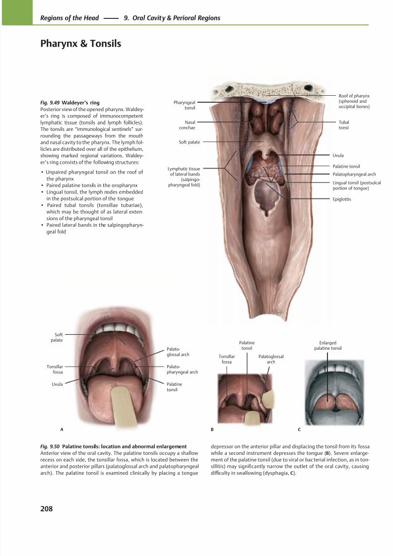
8/15/2019 Head and Neck Anatomy for Dental Medicine - Thieme; (January 26, 2010)
http://slidepdf.com/reader/full/head-and-neck-anatomy-for-dental-medicine-thieme-january-26-2010 221/384
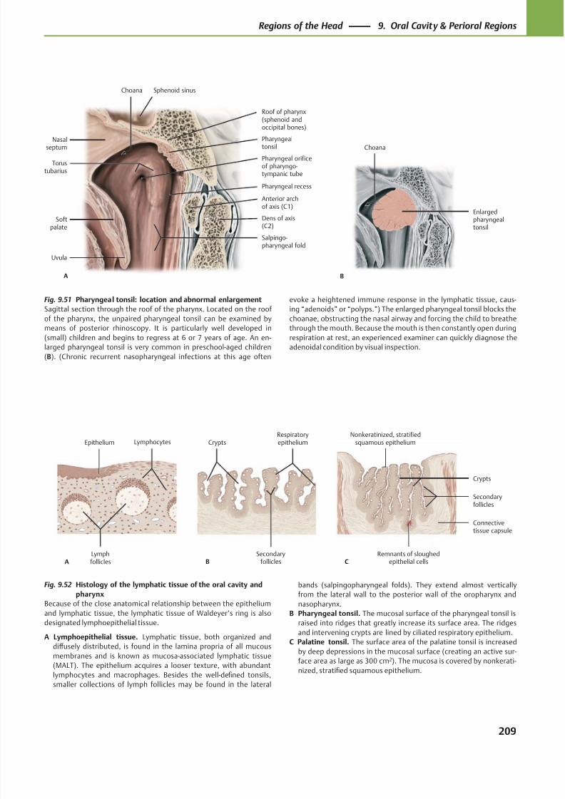
8/15/2019 Head and Neck Anatomy for Dental Medicine - Thieme; (January 26, 2010)
http://slidepdf.com/reader/full/head-and-neck-anatomy-for-dental-medicine-thieme-january-26-2010 222/384
Choana
Nasalseptum
Torustubarius
Softpalate
Uvula
Salpingo-pharyngeal fold
Dens of axis(C2)
Pharyngeal orificeof pharyngo-tympanic tube
Pharyngealtonsil
A
Sphenoid sinus
Anterior archof axis (C1)
Roof of pharynx(sphenoid andoccipital bones)
Pharyngeal recess
B
Choana
Enlargedpharyngealtonsil
Lymph
follicles
LymphocytesEpithelium
A
Secondary
follicles
RespiratoryepitheliumCrypts
B
Remnants of sloughed
epithelial cells
Connectivetissue capsule
Secondaryfollicles
Crypts
Nonkeratinized, stratifiedsquamous epithelium
C
Fig. 9.52 Histology of the lymphatic tissue of the oral cavity and
pharynx
Because of the close anatomical relationship between the epithelium
and lymphatic tissue, the lymphatic tissue of Waldeyer’s ring is also
designated lymphoepithelial tissue.
A Lymphoepithelial tissue. Lymphatic tissue, both organized and
diff usely distributed, is found in the lamina propria of all mucous
membranes and is known as mucosa-associated lymphatic tissue
(MALT). The epithelium acquires a looser texture, with abundant
lymphocytes and macrophages. Besides the well-defined tonsils,
smaller collections of lymph follicles may be found in the lateral
Fig. 9.51 Pharyngeal tonsil: location and abnormal enlargement
Sagittal section through the roof of the pharynx. Located on the roof
of the pharynx, the unpaired pharyngeal tonsil can be examined by
means of posterior rhinoscopy. It is particularly well developed in
(small) children and begins to regress at 6 or 7 years of age. An en-
larged pharyngeal tonsil is very common in preschool-aged children
(B). (Chronic recurrent nasopharyngeal infections at this age often
bands (salpingopharyngeal folds). They extend almost vertically
from the lateral wall to the posterior wall of the oropharynx and
nasopharynx.
B Pharyngeal tonsil. The mucosal surface of the pharyngeal tonsil is
raised into ridges that greatly increase its surface area. The ridges
and intervening crypts are lined by ciliated respiratory epithelium.
C Palatine tonsil. The surface area of the palatine tonsil is increased
by deep depressions in the mucosal surface (creating an active sur-
face area as large as 300 cm2). The mucosa is covered by nonkerati-
nized, stratified squamous epithelium.
evoke a heightened immune response in the lymphatic tissue, caus-
ing “adenoids” or “polyps.”) The enlarged pharyngeal tonsil blocks the
choanae, obstructing the nasal airway and forcing the child to breathe
through the mouth. Because the mouth is then constantly open during
respiration at rest, an experienced examiner can quickly diagnose the
adenoidal condition by visual inspection.
209
Regions of the Head 9. Oral Cavity & Perioral Regions
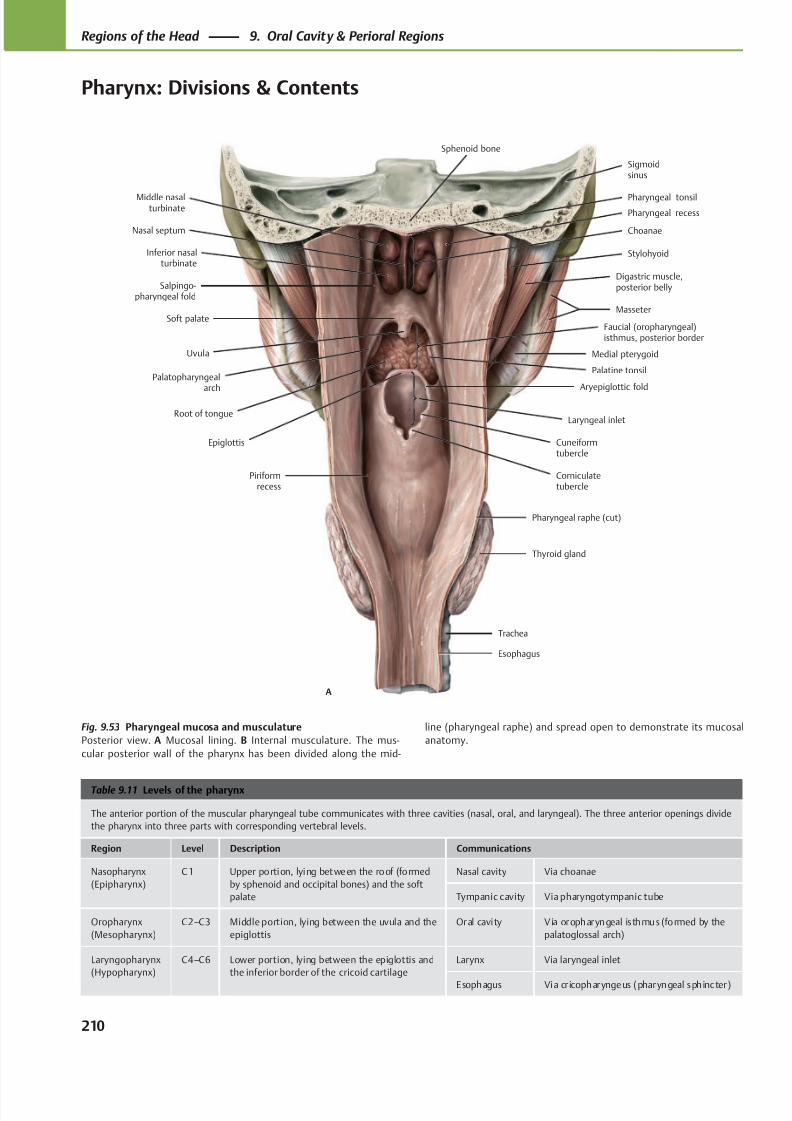
8/15/2019 Head and Neck Anatomy for Dental Medicine - Thieme; (January 26, 2010)
http://slidepdf.com/reader/full/head-and-neck-anatomy-for-dental-medicine-thieme-january-26-2010 223/384
Nasal septum
Soft palate
Thyroid gland
Corniculatetubercle
Cuneiformtubercle
Aryepiglottic fold
Epiglottis
Root of tongue
Medial pterygoidUvula
Faucial (oropharyngeal)isthmus, posterior border
Salpingo-pharyngeal fold
Masseter
Inferior nasalturbinate
Digastric muscle,posterior belly
Stylohyoid
Middle nasalturbinate
Choanae
Pharyngeal raphe (cut)
Laryngeal inlet
Piriformrecess
Pharyngeal tonsil
Sigmoidsinus
Palatopharyngeal
arch
Sphenoid bone
Pharyngeal recess
Palatine tonsil
A
Trachea
Esophagus
Table 9.11 Levels of the pharynx
The anterior portion of the muscular pharyngeal tube communicates with three cavities (nasal, oral, and laryngeal). The three anterior openings divide
the pharynx into three parts with corresponding vertebral levels.
Region Level Description Communications
Nasopharynx
(Epipharynx)
C1 Upper portion, lying between the roof (formed
by sphenoid and occipital bones) and the soft
palate
Nasal cavity Via choanae
Tympanic cavity Via pharyngotympanic tube
Oropharynx
(Mesopharynx)
C2–C3 Middle portion, lying between the uvula and the
epiglottis
Oral cavity V ia oropharyngeal is thmus (formed by the
palatoglossal arch)
Laryngopharynx
(Hypopharynx)
C4–C6 Lower portion, lying between the epiglottis and
the inferior border of the cricoid cartilage
Larynx Via laryngeal inlet
Esophagus Via cr icopharyngeus (pharyngeal sphincter)
Fig. 9.53 Pharyngeal mucosa and musculature
Posterior view. A Mucosal lining. B Internal musculature. The mus-
cular posterior wall of the pharynx has been divided along the mid-
line (pharyngeal raphe) and spread open to demonstrate its mucosal
anatomy.
210
Regions of the Head 9. Oral Cavity & Perioral Regions
Pharynx: Divisions & Contents
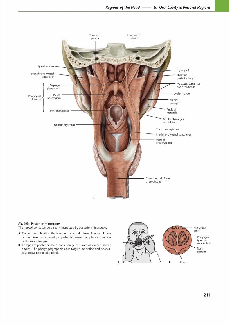
8/15/2019 Head and Neck Anatomy for Dental Medicine - Thieme; (January 26, 2010)
http://slidepdf.com/reader/full/head-and-neck-anatomy-for-dental-medicine-thieme-january-26-2010 224/384
Tensor velipalatini
Circular muscle fibersof esophagus
Posteriorcricoarytenoid
Transverse arytenoid
Middle pharyngealconstrictor
Digastric,posterior belly
Stylohyoid
Levator velipalatini
Medialpterygoid
Stylopharyngeus
Oblique arytenoid
Styloid process
Salpingo-pharyngeus
Palato-pharyngeus
Superior pharyngealconstrictor
Uvular musclePharyngeal
elevators
Angle of
mandible
Masseter, superficialand deep heads
B
Inferior pharyngeal constrictor
B
Nasalseptum
Pharyngealtonsil
Pharyngo-tympanictube orifice
UvulaA
Fig. 9.54 Posterior rhinoscopy
The nasopharynx can be visually inspected by posterior rhinoscopy.
A Technique of holding the tongue blade and mirror. The angulation
of the mirror is continually adjusted to permit complete inspection
of the nasopharynx.
B Composite posterior rhinoscopic image acquired at various mirror
-
211
Regions of the Head 9. Oral Cavity & Perioral Regions
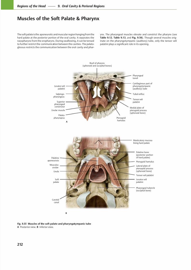
8/15/2019 Head and Neck Anatomy for Dental Medicine - Thieme; (January 26, 2010)
http://slidepdf.com/reader/full/head-and-neck-anatomy-for-dental-medicine-thieme-january-26-2010 225/384
Musculusuvulae
Softpalate
Levator velipalatini
Tensor veli palatini
Uvula
Pterygoid hamulus
Palatineaponeurosis
Masticatory mucosalining hard palate
Carotidcanal
Pharyngeal tubercle(occipital bone)
Palatine bone(posterior portionof hard palate)
Lateral plate of pterygoid process(sphenoid bone)
B
Palato-pharyngeus
Superiorpharyngealconstrictor
Salpingo-pharyngeus
Levator velipalatini
Pharyngealtonsil
Uvular muscle
Tubal orifice
Cartilaginous part ofpharyngotympanic(auditory) tube
Medial plate ofpterygoid process(sphenoid bone)
Pterygoidhamulus
Tensor velipalatini
Roof of pharynx(sphenoid and occipital bones)
A
The soft palate is the aponeurotic and muscular region hanging from the
hard palate at the posterior portion of the oral cavity. It separates the
nasopharynx from the oropharynx. During swallowing, it can be tensed
to further restrict the communication between the cavities. The palato-
glossus restricts the communication between the oral cavity and phar-
Fig. 9.55 Muscles of the soft palate and pharyngotympanic tube
A Posterior view. B Inferior view.
ynx. The pharyngeal muscles elevate and constrict the pharynx (see
Table 9.12, Table 9.13, and Fig. 9.56). Though several muscles orig-
inate on the pharyngotympanic (auditory) tube, only the tensor veli
212
Regions of the Head 9. Oral Cavity & Perioral Regions
Muscles of the Soft Palate & Pharynx
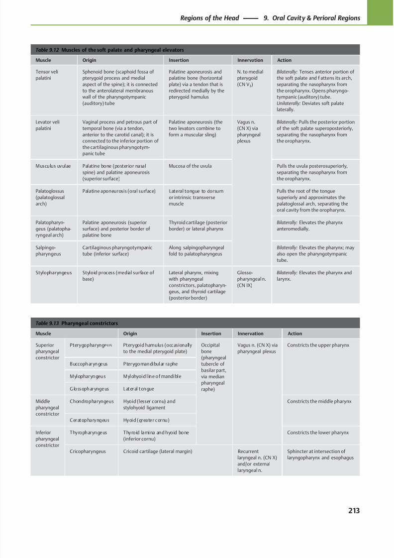
8/15/2019 Head and Neck Anatomy for Dental Medicine - Thieme; (January 26, 2010)
http://slidepdf.com/reader/full/head-and-neck-anatomy-for-dental-medicine-thieme-january-26-2010 226/384
Table 9.12 Muscles of the soft palate and pharyngeal elevators
Muscle Origin Insertion Innervation Action
Tensor veli
palatini
Sphenoid bone (scaphoid fossa of
pterygoid process and medial
aspect of the spine); it is connected
to the anterolateral membranous
wall of the pharyngotympanic(auditory) tube
Palatine aponeurosis and
palatine bone (horizontal
plate) via a tendon that is
redirected medially by the
pterygoid hamulus
N. to medial
pterygoid
(CN V3)
Bilaterally: Tenses anterior portion of
the soft palate and flattens its arch,
separating the nasopharynx from
the oropharynx. Opens pharyngo-
tympanic (auditory) tube.Unilaterally: Deviates soft palate
laterally.
Levator veli
palatini
Vaginal process and petrous part of
temporal bone (via a tendon,
anterior to the carotid canal); it is
connected to the inferior portion of
the cartilaginous pharyngotym-
panic tube
Palatine aponeurosis (the
two levators combine to
form a muscular sling)
Vagus n.
(CN X) via
pharyngeal
plexus
Bilaterally: Pulls the posterior portion
of the soft palate superoposteriorly,
separating the nasopharynx from
the oropharynx.
Musculus uvulae Palatine bone (posterior nasal
spine) and palatine aponeurosis
(superior surface)
Mucosa of the uvula Pulls the uvula posterosuperiorly,
separating the nasopharynx from
the oropharynx.
Palatoglossus
(palatoglossal
arch)
Palatine aponeurosis (oral surface) Lateral tongue to dorsum
or intrinsic transverse
muscle
Pulls the root of the tongue
superiorly and approximates the
palatoglossal arch, separating the
oral cavity from the oropharynx.
Palatopharyn-
geus (palatopha-
ryngeal arch)
Palatine aponeurosis (superior
surface) and posterior border of
palatine bone
Thyroid cartilage (posterior
border) or lateral pharynx
Bilaterally: Elevates the pharynx
anteromedially.
Salpingo-
pharyngeus
Cartilaginous pharyngotympanic
tube (inferior surface)
Along salpingopharyngeal
fold to palatopharyngeus
Bilaterally: Elevates the pharynx; may
also open the pharyngotympanic
tube.
Stylopharyngeus Styloid process (medial surface of
base)
Lateral pharynx, mixing
with pharyngeal
constrictors, palatopharyn-
geus, and thyroid cartilage(posterior border)
Glosso-
pharyngeal n.
(CN IX)
Bilaterally: Elevates the pharynx and
larynx.
Table 9.13 Pharyngeal constrictors
Muscle Origin Insertion Innervation Action
Superior
pharyngeal
constrictor
Pterygopharyngeus Pterygoid hamulus (occasionally
to the medial pterygoid plate)
Occipital
bone
(pharyngeal
tubercle of
basilar part,
via median
pharyngeal
raphe)
Vagus n. (CN X) via
pharyngeal plexus
Constricts the upper pharynx
Buccopharyngeus Pterygomandibular raphe
Mylopharyngeus Mylohyoid l ine of mandible
Glossopharyngeus Lateral tongue
Middle
pharyngeal
constrictor
Chondropharyngeus Hyoid (lesser cornu) and
stylohyoid ligament
Constricts the middle pharynx
Ceratopharyngeus Hyoid (greater cornu)
Inferior
pharyngeal
constrictor
Thyropharyngeus Thyroid lamina and hyoid bone
(inferior cornu)
Constricts the lower pharynx
Cricopharyngeus Cricoid cartilage (lateral margin) Recurrent
laryngeal n. (CN X)
and/or external
laryngeal n.
Sphincter at intersection of
laryngopharynx and esophagus
213
Regions of the Head 9. Oral Cavity & Perioral Regions
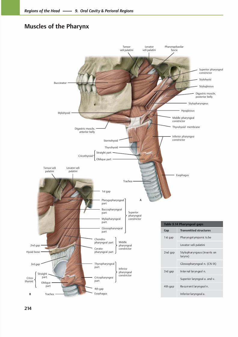
8/15/2019 Head and Neck Anatomy for Dental Medicine - Thieme; (January 26, 2010)
http://slidepdf.com/reader/full/head-and-neck-anatomy-for-dental-medicine-thieme-january-26-2010 227/384
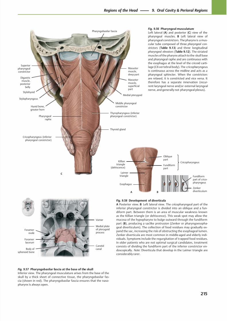
8/15/2019 Head and Neck Anatomy for Dental Medicine - Thieme; (January 26, 2010)
http://slidepdf.com/reader/full/head-and-neck-anatomy-for-dental-medicine-thieme-january-26-2010 228/384
Stylohyoid
Stylopharyngeus
Thyropharyngeus (inferiorpharyngeal constrictor)
Middle pharyngealconstrictor
Massetermuscle,superficialpart
Medial pterygoid
Massetermuscle,deep part
Digastricmuscle,
posteriorbelly
Superiorpharyngealconstrictor
Thyroid gland
Pharyngobasilar fascia
Pharyngealraphe
Hyoid bone,greater horn
C
Cricopharyngeus (inferiorpharyngeal constrictor)
Esophagus
Laimertriangle
Fundiform
part
Obliquepart
A
Killiantriangle
(dehiscence)
Cricopharyngeus
B
Zenkerdiverticulum
Fundiformpart of crico-pharyngeus
Vomer
Medial plateof pterygoidprocess
Foramenlacerum
Foramenovale
Body of sphenoid bone
Carotidcanal
Fig. 9.56 Pharyngeal musculature
Left lateral (A) and posterior (C) view of the
pharyngeal muscles. B Left lateral view of
pharyngeal constrictors. The pharynx is a mus-
cular tube composed of three pharyngeal con-
strictors (Table 9.13) and three longitudinal
pharyngeal elevators (Table 9.12). The striated
muscles of the pharynx attach to the skull baseand pharyngeal raphe and are continuous with
the esophagus at the level of the cricoid carti-
lage (C6 vertebral body). The cricopharyngeus
is continuous across the midline and acts as a
pharyngeal sphincter. When the constrictors
are relaxed, it is constricted and vice versa. It
therefore has a separate innervation (recur-
rent laryngeal nerve and/or external laryngeal
nerve, and generally not pharyngeal plexus).
Fig. 9.58 Development of diverticula
A Posterior view. B Left lateral view. The cricopharyngeal part of the
inferior pharyngeal constrictor is divided into an oblique and a fun-
diform part. Between them is an area of muscular weakness known
as the Killian triangle (or dehiscence). This weak spot may allow the
mucosa of the hypopharynx to bulge outward through the fundiform
part (B), producing a saclike protrusion (Zenker or pharyngoesopha-geal diverticulum). The collection of food residues may gradually ex-
pand the sac, increasing the risk of obstructing the esophageal lumen.
Zenker diverticula are most common in middle-aged and elderly indi-
viduals. Symptoms include the regurgitation of t rapped food residues.
In older patients who are not optimal surgical candidates, treatment
consists of dividing the fundiform part of the inferior constrictor en-
doscopically. Note: Diverticula that develop in the Laimer triangle are
considerably rarer.
Fig. 9.57 Pharyngobasilar fascia at the base of the skull
Inferior view. The pharyngeal musculature arises from the base of the
skull by a thick sheet of connective tissue, the pharyngobasilar fas-
cia (shown in red). The pharyngobasilar fascia ensures that the naso-pharynx is always open.
215
Regions of the Head 9. Oral Cavity & Perioral Regions
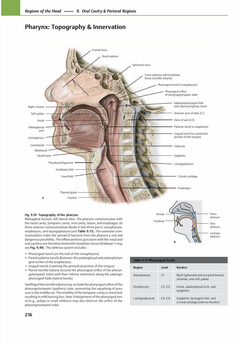
8/15/2019 Head and Neck Anatomy for Dental Medicine - Thieme; (January 26, 2010)
http://slidepdf.com/reader/full/head-and-neck-anatomy-for-dental-medicine-thieme-january-26-2010 229/384
Genioglossus
Geniohyoid
Hyoid bone
Thyrohyoid ligament
Thyroid gland
Vocal fold
Vestibular fold
Palatoglossalarch
Uvula Dens of axis (C2)
Soft palate Anterior arch of atlas (C1)
Salpingopharyngeal foldwith lateral lymphatic band
Pharyngeal orificeof pharyngotympanic tube
Pharyngeal tonsil in nasopharynx
Torus tubarius with lymphatictissue (tonsilla tubaria)
Palatine tonsil in oropharynx
Lingual tonsil (on postsulcalportion of the tongue)
Right choana
Cricoid cartilage
Epiglottis
Trachea
Frontal sinus
Nasal septum
Sphenoid sinus
Vallecula
Laryngopharynx
Esophagus
A
Mylohyoid
Naso-pharynx
Oro-pharynx
Laryngo-pharynx
Airway
Foodway
B
Table 9.15 Pharyngeal levels
Region Level Borders
Nasopharynx C1 Roof (sphenoid and occipital bones),
choanae, and soft palate
Oropharynx C2–C3 Uvula, palatoglossal arch, and
epiglottis
Laryngopharynx C4–C6 Epiglottis, laryngeal in let , and
cricoid cartilage (inferior border)
Fig. 9.59 Topography of the pharynx
Midsagittal section, left lateral view. The pharynx communicates with
the nasal cavity, tympanic cavity, oral cavity, larynx, and esophagus. Its
three anterior communications divide it into three parts: nasopharynx,
oropharynx, and laryngopharynx (see Table 9.15). The extensive com-
munications make the spread of bacteria from the pharynx a real and
dangerous possibility. The infl
ow portions (junctions with the nasal andoral cavities) are therefore lined with lymphatic tissue (Waldeyer’s ring;
see Fig. 9.49). This defense system includes:
• Pharyngeal tonsil (on the roof of the nasopharynx)
• Paired palatine tonsils (between the palatoglossal and palatopharyn-
geal arches of the oropharynx)
• Lingual tonsils (covering the postsulcal portion of the tongue)
• Paired tonsilla tubaria (around the pharyngeal orifice of the pharyn-
gotympanic tube) with their inferior extensions along the salpingo-
pharyngeal folds (lateral bands)
Swelling of the tonsilla tubaria may occlude the pharyngeal orifice of the
pharyngotympanic (auditory) tube, preventing the equalizing of pres-
sure in the middle ear. The mobility of the tympanic cavity is restricted,
resulting in mild hearing loss. Note: Enlargement of the pharyngeal ton-
sil (e.g., polyps in small children) may also obstruct the orifice of thepharyngotympanic tube.
216
Regions of the Head 9. Oral Cavity & Perioral Regions
Pharynx: Topography & Innervation
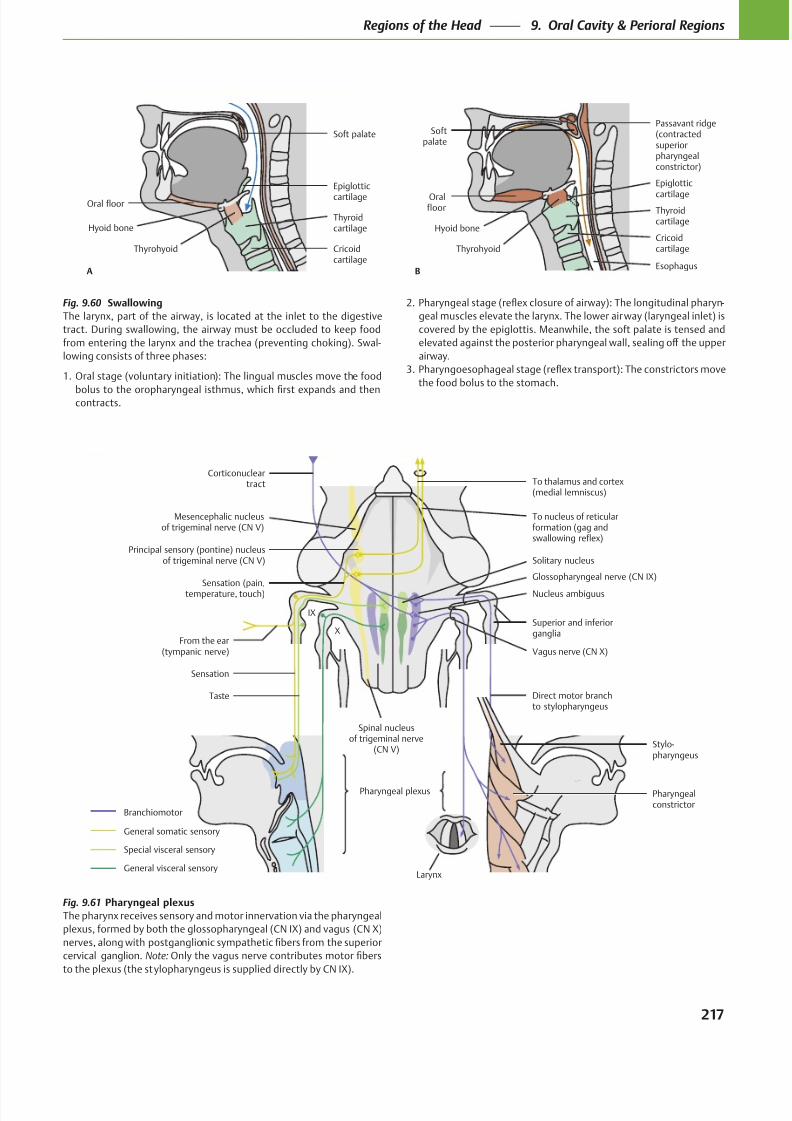
8/15/2019 Head and Neck Anatomy for Dental Medicine - Thieme; (January 26, 2010)
http://slidepdf.com/reader/full/head-and-neck-anatomy-for-dental-medicine-thieme-january-26-2010 230/384
To thalamus and cortex(medial lemniscus)
To nucleus of reticularformation (gag andswallowing reflex)
Sensation (pain,temperature, touch)
From the ear(tympanic nerve)
Spinal nucleusof trigeminal nerve
(CN V)
Sensation
Taste
Pharyngealconstrictor
Stylo-pharyngeus
Vagus nerve (CN X)
Superior and inferiorganglia
Nucleus ambiguus
Solitary nucleusPrincipal sensory (pontine) nucleus
of trigeminal nerve (CN V)
Mesencephalic nucleusof trigeminal nerve (CN V)
Special visceral sensory
General somatic sensory
Branchiomotor
Corticonucleartract
IX
X
Glossopharyngeal nerve (CN IX)
Direct motor branchto stylopharyngeus
Pharyngeal plexus
General visceral sensoryLarynx
A
Oral floor
Thyroidcartilage
Cricoidcartilage
Epiglottic
cartilage
Thyrohyoid
Hyoid bone
Soft palate
Oralfloor Thyroid
cartilage
Cricoidcartilage
Epiglottic
cartilage
Passavant ridge(contractedsuperiorpharyngealconstrictor)
B
Thyrohyoid
Hyoid bone
Softpalate
Esophagus
Fig. 9.61 Pharyngeal plexus
The pharynx receives sensory and motor innervation via the pharyngeal
plexus, formed by both the glossopharyngeal (CN IX) and vagus (CN X)
cervical ganglion. Note:
to the plexus (the stylopharyngeus is supplied directly by CN IX).
Fig. 9.60 Swallowing
The larynx, part of the airway, is located at the inlet to the digestive
tract. During swallowing, the airway must be occluded to keep food
from entering the larynx and the trachea (preventing choking). Swal-
lowing consists of three phases:
1. Oral stage (voluntary initiation): The lingual muscles move the food
contracts.
-
geal muscles elevate the larynx. The lower airway (laryngeal inlet) is
covered by the epiglottis. Meanwhile, the soft palate is tensed and
airway.
the food bolus to the stomach.
217
Regions of the Head 9. Oral Cavity & Perioral Regions
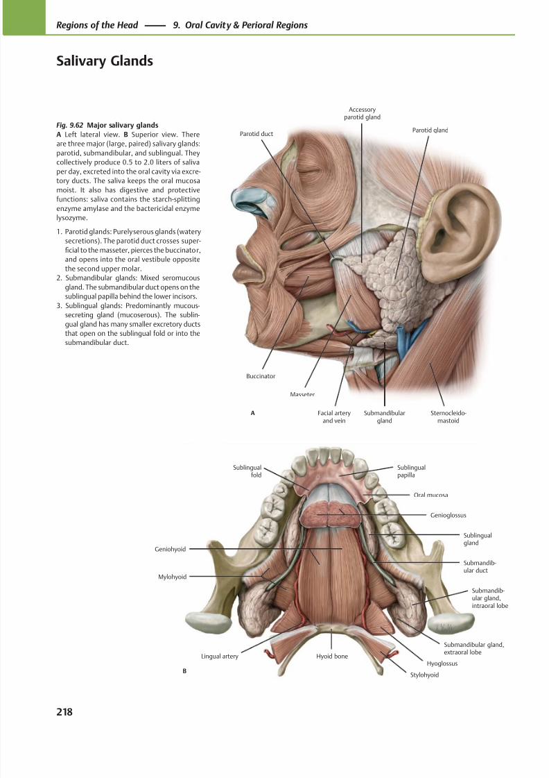
8/15/2019 Head and Neck Anatomy for Dental Medicine - Thieme; (January 26, 2010)
http://slidepdf.com/reader/full/head-and-neck-anatomy-for-dental-medicine-thieme-january-26-2010 231/384
Buccinator
Parotid duct
Masseter
Facial arteryand vein
Submandibulargland
Sternocleido-mastoid
Parotid gland
Accessoryparotid gland
A
Sublingualfold
Genioglossus
Geniohyoid
Mylohyoid
Hyoid boneLingual artery
Submandib-ular gland,intraoral lobe
Submandib-ular duct
Sublingual
gland
Oral mucosa
Sublingualpapilla
BStylohyoid
Hyoglossus
Submandibular gland,extraoral lobe
Fig. 9.62 Major salivary glands
A Left lateral view. B Superior view. Thereare three major (large, paired) salivary glands:
parotid, submandibular, and sublingual. They
collectively produce 0.5 to 2.0 liters of saliva
per day, excreted into the oral cavity via excre-
tory ducts. The saliva keeps the oral mucosa
moist. It also has digestive and protective
functions: saliva contains the starch-splitting
enzyme amylase and the bactericidal enzyme
lysozyme.
1. Parotid glands: Purely serous glands (watery
secretions). The parotid duct crosses super-
ficial to the masseter, pierces the buccinator,
and opens into the oral vestibule opposite
the second upper molar.2. Submandibular glands: Mixed seromucous
gland. The submandibular duct opens on the
sublingual papilla behind the lower incisors.
3. Sublingual glands: Predominantly mucous-
secreting gland (mucoserous). The sublin-
gual gland has many smaller excretory ducts
that open on the sublingual fold or into the
submandibular duct.
218
Regions of the Head 9. Oral Cavity & Perioral Regions
Salivary Glands
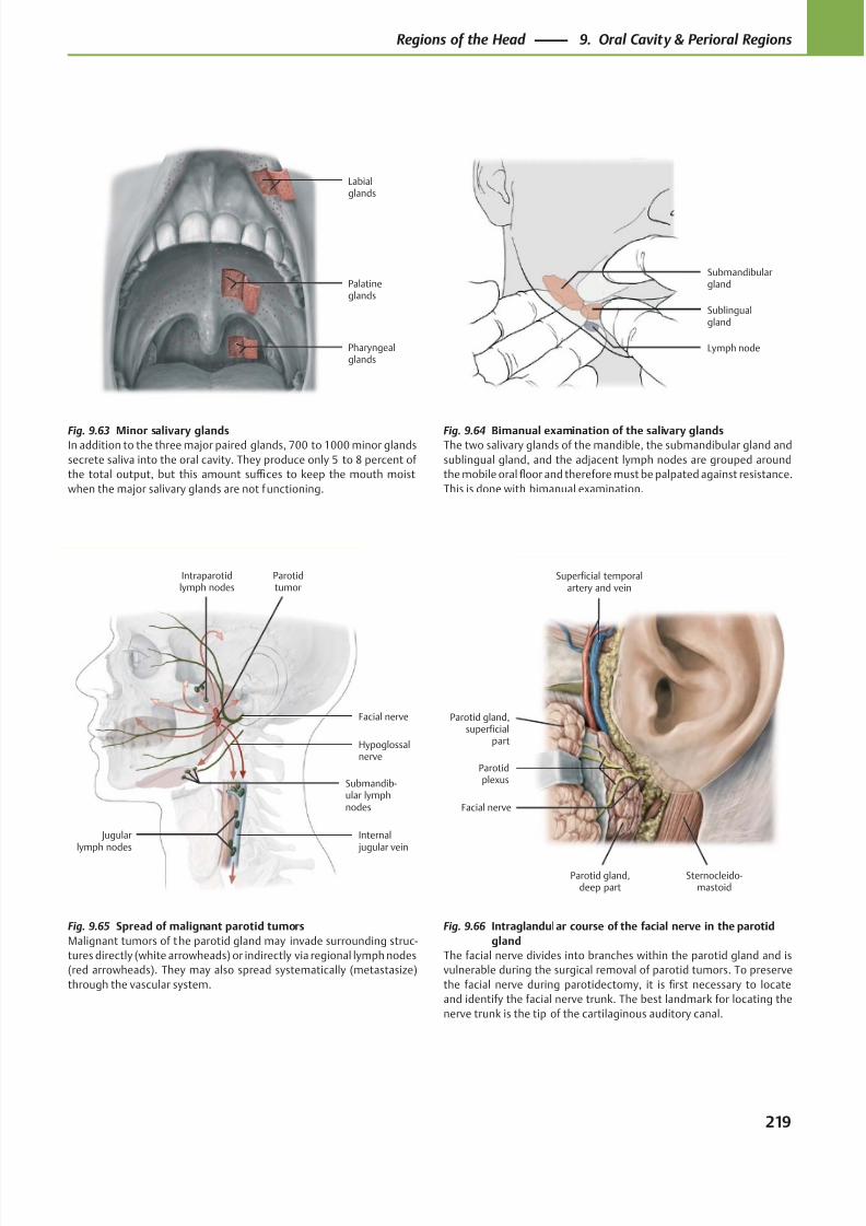
8/15/2019 Head and Neck Anatomy for Dental Medicine - Thieme; (January 26, 2010)
http://slidepdf.com/reader/full/head-and-neck-anatomy-for-dental-medicine-thieme-january-26-2010 232/384
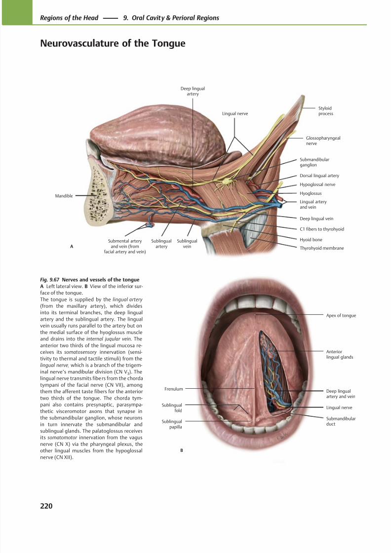
8/15/2019 Head and Neck Anatomy for Dental Medicine - Thieme; (January 26, 2010)
http://slidepdf.com/reader/full/head-and-neck-anatomy-for-dental-medicine-thieme-january-26-2010 233/384
Anteriorlingual glands
Apex of tongue
B
Submandibularduct
Lingual nerve
Deep lingualartery and vein
Frenulum
Sublingualfold
Sublingualpapilla
Deep lingualartery
Sublingualartery
Mandible
Submental arteryand vein (from
facial artery and vein)
Hyoid bone
Submandibularganglion
Lingual arteryand vein
Hypoglossal nerve
Glossopharyngealnerve
StyloidprocessLingual nerve
A
Dorsal lingual artery
C1 fibers to thyrohyoid
Sublingualvein
Deep lingual vein
Hyoglossus
Thyrohyoid membrane
Fig. 9.67 Nerves and vessels of the tongue
A Left lateral view. B View of the inferior sur-
face of the tongue.
The tongue is supplied by the lingual artery
(from the maxillary artery), which divides
into its terminal branches, the deep lingual
artery and the sublingual artery. The lingual
vein usually runs parallel to the artery but on
the medial surface of the hyoglossus muscle
and drains into the internal jugular vein. The
anterior two thirds of the lingual mucosa re-
ceives its somatosensory innervation (sensi-
tivity to thermal and tactile stimuli) from the
lingual nerve, which is a branch of the trigem-
inal nerve’s mandibular division (CN V3). The
lingual nerve transmits fibers from the chorda
tympani of the facial nerve (CN VII), amongthem the afferent taste fibers for the anterior
two thirds of the tongue. The chorda tym-
pani also contains presynaptic, parasympa-
thetic visceromotor axons that synapse in
the submandibular ganglion, whose neurons
in turn innervate the submandibular and
sublingual glands. The palatoglossus receives
its somatomotor innervation from the vagus
nerve (CN X) via the pharyngeal plexus, the
other lingual muscles from the hypoglossal
nerve (CN XII).
220
Regions of the Head 9. Oral Cavity & Perioral Regions
Neurovasculature of the Tongue
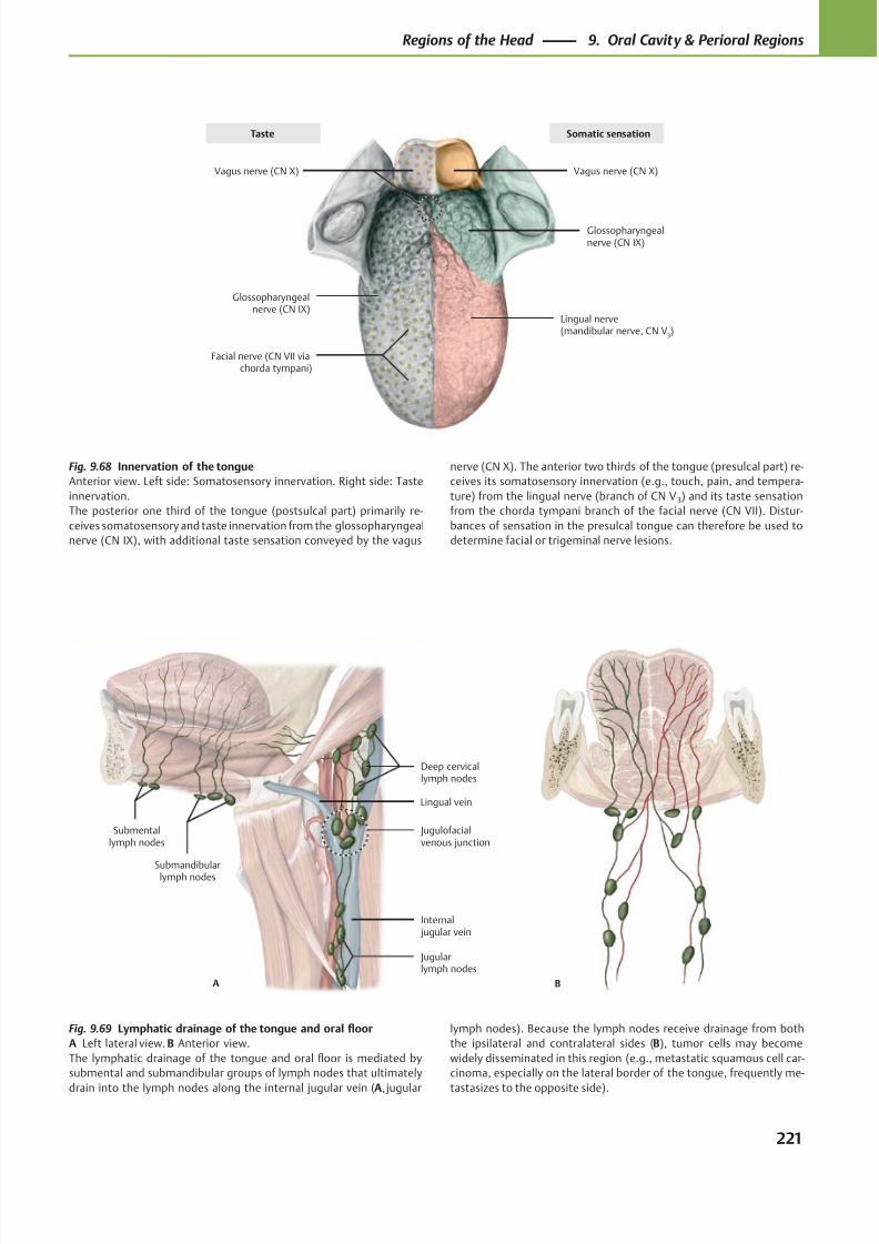
8/15/2019 Head and Neck Anatomy for Dental Medicine - Thieme; (January 26, 2010)
http://slidepdf.com/reader/full/head-and-neck-anatomy-for-dental-medicine-thieme-january-26-2010 234/384
Vagus nerve (CN X)
Glossopharyngealnerve (CN IX)
Facial nerve (CN VII viachorda tympani)
Lingual nerve(mandibular nerve, CN V
3)
Glossopharyngealnerve (CN IX)
Vagus nerve (CN X)
Taste Somatic sensation
BA
Submentallymph nodes
Submandibularlymph nodes
Internal jugular vein
Jugulofacialvenous junction
Deep cervicallymph nodes
Jugularlymph nodes
Lingual vein
Fig. 9.68 Innervation of the tongue
Anterior view. Left side: Somatosensory innervation. Right side: Taste
innervation.
The posterior one third of the tongue (postsulcal part) primarily re-
ceives somatosensory and taste innervation from the glossopharyngeal
nerve (CN IX), with additional taste sensation conveyed by the vagus
Fig. 9.69 Lymphatic drainage of the tongue and oral floor
A Left lateral view. B Anterior view.
The lymphatic drainage of the tongue and oral floor is mediated by
submental and submandibular groups of lymph nodes that ultimately
drain into the lymph nodes along the internal jugular vein (A, jugular
lymph nodes). Because the lymph nodes receive drainage from both
the ipsilateral and contralateral sides (B), tumor cells may become
widely disseminated in this region (e.g., metastatic squamous cell car-
cinoma, especially on the lateral border of the tongue, frequently me-
tastasizes to the opposite side).
nerve (CN X). The anterior two thirds of the tongue (presulcal part) re-
ceives its somatosensory innervation (e.g., touch, pain, and tempera-
ture) from the lingual nerve (branch of CN V 3) and its taste sensation
from the chorda tympani branch of the facial nerve (CN VII). Distur-
bances of sensation in the presulcal tongue can therefore be used to
determine facial or trigeminal nerve lesions.
221
Regions of the Head 9. Oral Cavity & Perioral Regions
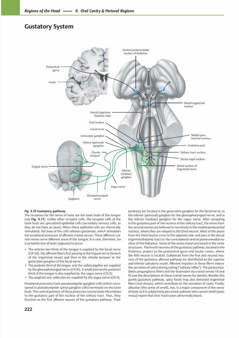
8/15/2019 Head and Neck Anatomy for Dental Medicine - Thieme; (January 26, 2010)
http://slidepdf.com/reader/full/head-and-neck-anatomy-for-dental-medicine-thieme-january-26-2010 235/384
Postcentralgyrus
Insula
Solitary tract nucleus
Epiglottis
Chordatympani
Vagus nerve
Glossopharyngealnerve
Geniculate ganglion
Ventral posteromedialnucleus of thalamus
Dorsal tegmentalnucleus
Facial nerve
Medial para-brachial nucleus
Spinal nucleus of trigeminal nerve
Dorsal vagal nucleus
Gustatory partInferior (petrosal)
ganglion
Dorsal trigemino-thalamic tract
Inferior(nodose)
ganglion
Lingual nerve
Oval nucleus
Fig. 9.70 Gustatory pathway
The receptors for the sense of taste are the taste buds of the tongue
(see Fig. 9.71). Unlike other receptor cells, the receptor cells of the
taste buds are specialized epithelial cells (secondary sensory cells, as
they do not have an axon). When these epithelial cells are chemically
stimulated, the base of the cells releases glutamate, which stimulates
the peripheral processes of aff erent cranial nerves. These diff erent cra-nial nerves serve diff erent areas of the tongue. It is rare, therefore, for
a complete loss of taste (ageusia) to occur.
• The anterior two thirds of the tongue is supplied by the facial nerve
(CN VII), the aff erent fibers first passing in the lingual nerve (branch
of the trigeminal nerve) and then in the chorda tympani to the
geniculate ganglion of the facial nerve.
• The posterior third of the tongue and the vallate papillae are supplied
by the glossopharyngeal nerve (CN IX). A small area on the posterior
third of the tongue is also supplied by the vagus nerve (CN X).
• The epiglottis and valleculae are supplied by the vagus nerve (CN X).
Peripheral processes from pseudounipolar ganglion cells (which corre-
spond to pseudounipolar spinal ganglion cells) terminate on the taste
buds. The central portions of these processes convey taste information
to the gustatory part of the nucleus of the solitary tract. Thus, theyfunction as the first aff erent neuron of the gustatory pathway. Their
perikarya are located in the geniculate ganglion for the facial nerve, in
the inferior (petrosal) ganglion for the glossopharyngeal ner ve, and in
the inferior (nodose) ganglion for the vagus nerve. After synapsing
in the gustatory part of the nucleus of the solitary tract, the axons from
the second neuron are believed to terminate in the medial parabrachial
nucleus, where they are relayed to the third neuron. Most of the axons
from the third neuron cross to the opposite side and pass in the dorsaltrigeminothalamic tract to the contralateral ventral posteromedial nu-
cleus of the thalamus. Some of the axons travel uncrossed in the same
structures. The fourth neurons of the gustatory pathway, located in the
thalamus, project to the postcentral gyrus and insular cortex, where
the fifth neuron is located. Collaterals from the first and second neu-
rons of the gustatory aff erent pathway are distributed to the superior
and inferior salivatory nuclei. Aff erent impulses in these fibers induce
the secretion of saliva during eating (“salivary reflex”). The parasympa-
thetic preganglionic fibers exit the brainstem via cranial nerves VII and
IX (see the descriptions of these cranial nerves for details). Besides this
purely gustatory pathway, spicy foods may also stimulate trigeminal
fibers (not shown), which contribute to the sensation of taste. Finally,
olfaction (the sense of smell), too, is a major component of the sense
of taste as it is subjectively perceived: patients who cannot smell (anos-
mosia) report that their food tastes abnormally bland.
222
Regions of the Head 9. Oral Cavity & Perioral Regions
Gustatory System
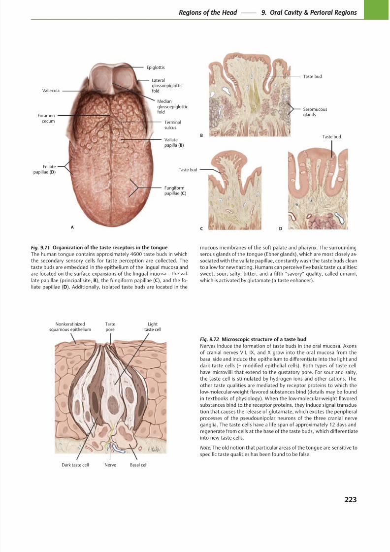
8/15/2019 Head and Neck Anatomy for Dental Medicine - Thieme; (January 26, 2010)
http://slidepdf.com/reader/full/head-and-neck-anatomy-for-dental-medicine-thieme-january-26-2010 236/384
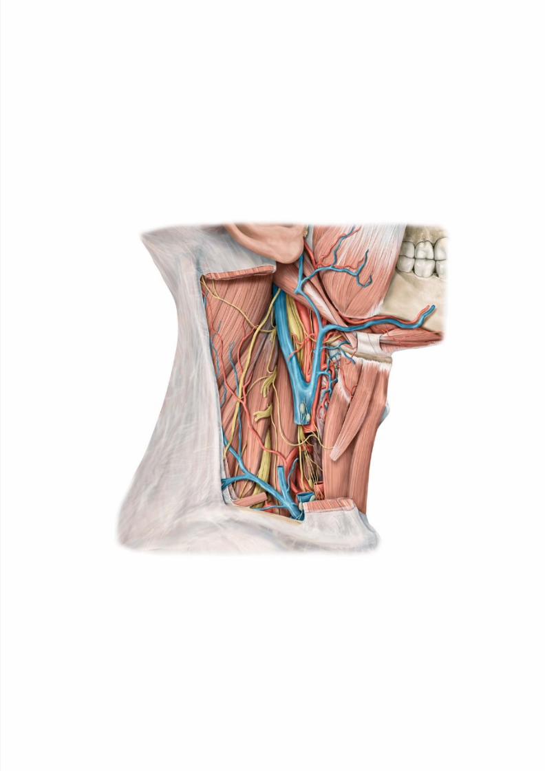
8/15/2019 Head and Neck Anatomy for Dental Medicine - Thieme; (January 26, 2010)
http://slidepdf.com/reader/full/head-and-neck-anatomy-for-dental-medicine-thieme-january-26-2010 237/384
8/15/2019 Head and Neck Anatomy for Dental Medicine - Thieme; (January 26, 2010)
http://slidepdf.com/reader/full/head-and-neck-anatomy-for-dental-medicine-thieme-january-26-2010 238/384
Neck
10 Bones, Ligaments & Muscles of the Neck
Vertebral Column & Vertebrae . . . . . . . . . . . . . . . . . . . . . . . .226
Ligaments of the Vertebral Column . . . . . . . . . . . . . . . . . . . . 228
Cervical Spine . . . . . . . . . . . . . . . . . . . . . . . . . . . . . . . . . . . . . 230
Joints of the Cervical Spine . . . . . . . . . . . . . . . . . . . . . . . . . . . 232
Ligaments of the Cervical Spine . . . . . . . . . . . . . . . . . . . . . . . 234
Ligaments of the Craniovertebral Joints . . . . . . . . . . . . . . . .236
Muscles of the Neck: Overview. . . . . . . . . . . . . . . . . . . . . . . . 238
Muscles of the Neck & Back (I) . . . . . . . . . . . . . . . . . . . . . . . . 240Muscles of the Neck & Back (II) . . . . . . . . . . . . . . . . . . . . . . . . 242
Muscles of the Posterior Neck . . . . . . . . . . . . . . . . . . . . . . . . 244
Intrinsic Back Muscles (I): Erector Spinae &
Interspinales . . . . . . . . . . . . . . . . . . . . . . . . . . . . . . . . . . . . .246
Intrinsic Back Muscles (II) . . . . . . . . . . . . . . . . . . . . . . . . . . . . 248
Intrinsic Back Muscles (III): Short Nuchal
Muscles . . . . . . . . . . . . . . . . . . . . . . . . . . . . . . . . . . . . . . . . .250
Prevertebral & Scalene Muscles . . . . . . . . . . . . . . . . . . . . . . . 252
Suprahyoid & Infrahyoid Muscles . . . . . . . . . . . . . . . . . . . . . .254
11 Larynx
Larynx . . . . . . . . . . . . . . . . . . . . . . . . . . . . . . . . . . . . . . . . . . . .256
Laryngeal Muscles . . . . . . . . . . . . . . . . . . . . . . . . . . . . . . . . . . 258Larynx: Neurovasculature . . . . . . . . . . . . . . . . . . . . . . . . . . . . 260
Larynx: Topography . . . . . . . . . . . . . . . . . . . . . . . . . . . . . . . . . 262
Thyroid & Parathyroid Glands . . . . . . . . . . . . . . . . . . . . . . . . . 264
12 Neurovascular Topography of the Neck
Arteries & Veins of the Neck . . . . . . . . . . . . . . . . . . . . . . . . . . 266
Lymphatics of the Neck . . . . . . . . . . . . . . . . . . . . . . . . . . . . . . 268
Cervical Plexus . . . . . . . . . . . . . . . . . . . . . . . . . . . . . . . . . . . . . 270
Cervical Regions (Triangles) . . . . . . . . . . . . . . . . . . . . . . . . . . 272
Cervical Fasciae . . . . . . . . . . . . . . . . . . . . . . . . . . . . . . . . . . . .274
Posterior Neck . . . . . . . . . . . . . . . . . . . . . . . . . . . . . . . . . . . . .276
Lateral Neck . . . . . . . . . . . . . . . . . . . . . . . . . . . . . . . . . . . . . . . 278
Anterior Neck . . . . . . . . . . . . . . . . . . . . . . . . . . . . . . . . . . . . . .280Deep Anterolateral Neck . . . . . . . . . . . . . . . . . . . . . . . . . . . . . 282
Parapharyngeal Space (I). . . . . . . . . . . . . . . . . . . . . . . . . . . . . 284
Parapharyngeal Space (II) . . . . . . . . . . . . . . . . . . . . . . . . . . . . 286
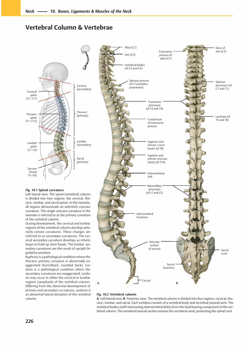
8/15/2019 Head and Neck Anatomy for Dental Medicine - Thieme; (January 26, 2010)
http://slidepdf.com/reader/full/head-and-neck-anatomy-for-dental-medicine-thieme-january-26-2010 239/384
Sacrum(fused
S1–S5)
Lumbarspine
(L1–L5)
Thoracicspine
(T1–T12)
Cervicalspine
(C1–C7)
Sacral(primary)
Lumbar(secondary)
Thoracic(primary)
Cervical(secondary)
Spinous processof C7 (vertebraprominens)
Axis (C2)
Atlas (C1)
ACoccyx
Vertebral bodies(of C3 and C4)
Transverseprocesses
(of T3 and T4)
Costal facet
of transverseprocess
Superior andinferior costalfacets (of T8)
Superior andinferior articularfacets (of T10)
Intervertebraldisk
Mammillaryprocesses
(of L1 and L2)
Intervertebralforamina
Articular
surfaceof sacrum
Sacralforamina
Spinousprocesses (ofC7 and T1)
Transverseprocess of atlas (C1)
Dens ofaxis (C2)
B
Sacralcrest
Laminae (ofT5 and T6)
Fig. 10.1 Spinal curvature
Left lateral view. The spinal (vertebral) column
is divided into four regions: the cervical, tho-
racic, lumbar, and sacral spines. In the neonate,
all regions demonstrate an anteriorly concave
curvature. This single concave curvature in the
neonate is referred to as the primary curvature
of the vertebral column.
During development, the cervical and lumbar
regions of the vertebral column develop ante-
riorly convex curvatures. These changes are
referred to as secondary curvatures. The cer-
vical secondary curvature develops as infants
begin to hold up their heads. The lumbar sec-ondary curvatures are the result of upright bi-
pedal locomotion.
Kyphosis is a pathological condition where the
thoracic primary curvature is abnormally ex-
aggerated (hunchback, rounded back). Lor-
dosis is a pathological condition where the
secondary curvatures are exaggerated. Lordo-
sis may occur in either the cervical or lumbar
regions (swayback) of the vertebral column.
Diff ering from the abnormal development of
primary and secondary curvatures, scoliosis is
an abnormal lateral deviation of the vertebral
column.
Fig. 10.2 Vertebral column
A Left lateral view. B Posterior view. The vertebral column is divided into four regions: cervical, tho-
racic, lumbar, and sacral. Each vertebra consists of a vertebral body and vertebral (neural) arch. The
vertebral bodies (with intervening intervertebral disks) form the load-bearing component of the ver-tebral column. The vertebral (neural) arches enclose the vertebral canal, protecting the spinal cord.
226
Neck 10. Bones, Ligaments & Muscles of the Neck
Vertebral Column & Vertebrae
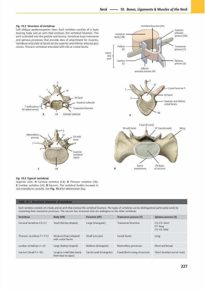
8/15/2019 Head and Neck Anatomy for Dental Medicine - Thieme; (January 26, 2010)
http://slidepdf.com/reader/full/head-and-neck-anatomy-for-dental-medicine-thieme-january-26-2010 240/384
Verte-bralarch
Pedicle(P)
Lamina(L)
Inferiorarticular process (IA)
Spinousprocess (S)
Superiorarticularprocess (SA)
Transverseprocess (T)
Vertebralbody (VB)
Vertebral foramen (VF)
A
VF
Transverse foramen
SA facet
Posterior tubercle
Anterior tubercleVB
L
S
P
T (with sulcusfor spinal nerve)
L
P
VB
Superior and inferiorcostal facets
SA facet
T
S
Costal facet on T
B
VF
C
S
VFSA withfacet
Superiorvertebralnotch
VB
P
T
Mammillaryprocess
L
D
SA with facet
S (sacral crest)
VF (sacral canal) Wing
Sacralpromontory
VB (baseof sacrum)
Table 10.1 Structural elements of vertebrae
Each vertebra consists of a body and an arch that enclose the vertebral foramen. The types of vertebrae can be distinguished particularly easily by
examining their transverse processes. The sacrum has structures that are analogous to the other vertebrae.
Vertebrae Body (VB) Foramen (VF) Transverse process (T) Spinous process (S)
Cervical vertebrae C3–C7 Small (kidney-shaped) Large (triangular) Transverse foramina C3–C5: short
C7: long
C3–C6: bifid
Thoracic vertebrae T1–T12 Medium (heart-shaped)
with costal facets
Small (circular) Costal facets Long
Lumbar vertebrae L1–L5 Large (kidney-shaped) Medium (triangular) Mammillary processes Short and broad
Sacrum ( fused S1–S5) Large to smal l (decreases
from base to apex)
Sacral canal (triangular) Fused (forms wing of sacrum) Short (median sacral crest)
Fig. 10.3 Structure of vertebrae
Left oblique posterosuperior view. Each vertebra consists of a load-
bearing body and an arch that encloses the vertebral foramen. The
arch is divided into the pedicle and lamina. Vertebrae have transverse
and spinous processes that provide sites of attachment for muscles.
Vertebrae articulate at facets on the superior and inferior articular pro-
cesses. Thoracic vertebrae articulate with ribs at costal facets.
Fig. 10.4 Typical vertebrae
Superior view. A Cervical vertebra (C4). B Thoracic vertebra (T6).
C Lumbar vertebra (L4). D Sacrum. The vertebral bodies increase in
size cranially to caudally. See Fig. 10.3 for abbreviation key.
227
Neck 10. Bones, Ligaments & Muscles of the Neck
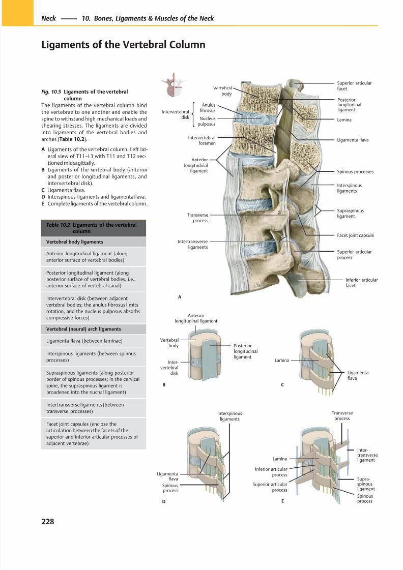
8/15/2019 Head and Neck Anatomy for Dental Medicine - Thieme; (January 26, 2010)
http://slidepdf.com/reader/full/head-and-neck-anatomy-for-dental-medicine-thieme-january-26-2010 241/384
PosteriorlongitudinalligamentIntervertebral
disk
Anulusfibrosus
Nucleuspulposus
Anteriorlongitudinal
ligament
Intertransverseligaments
Intervertebralforamen
Inferior articularfacet
Facet joint capsule
Transverseprocess
Interspinousligaments
Spinous processes
Ligamenta flava
Lamina
Superior articularfacet
A
Vertebralbody
Supraspinousligament
Superior articularprocess
Anteriorlongitudinal ligament
Vertebralbody
Inter-vertebral
disk
Posteriorlongitudinalligament
B
Lamina
Inferior articularprocess
Superior articularprocess
Spinousprocess
Supra-spinousligament
Inter-transverseligament
Transverseprocess
E
Ligamentaflava
Interspinousligaments
Spinousprocess
D
Lamina
Ligamentaflava
C
Table 10.2 Ligaments of the vertebralcolumn
Vertebral body ligaments
Anterior longitudinal ligament (along
anterior surface of vertebral bodies)
Posterior longitudinal ligament (along
posterior surface of vertebral bodies, i.e.,
anterior surface of vertebral canal)
Intervertebral disk (between adjacentvertebral bodies; the anulus fibrosus limits
rotation, and the nucleus pulposus absorbs
compressive forces)
Vertebral (neural) arch ligaments
Ligamenta flava (between laminae)
Interspinous ligaments (between spinous
processes)
Supraspinous ligaments (along posterior
border of spinous processes; in the cervical
spine, the supraspinous ligament is
broadened into the nuchal ligament)
Intertransverse ligaments (between
transverse processes)
Facet joint capsules (enclose the
articulation between the facets of the
superior and inferior articular processes of
adjacent vertebrae)
Fig. 10.5 Ligaments of the vertebral
columnThe ligaments of the vertebral column bind
the vertebrae to one another and enable the
spine to withstand high mechanical loads and
shearing stresses. The ligaments are divided
into ligaments of the vertebral bodies and
arches (Table 10.2).
A Ligaments of the vertebral column. Left lat-
eral view of T11–L3 with T11 and T12 sec-
tioned midsagittally.
B Ligaments of the vertebral body (anterior
and posterior longitudinal ligaments, and
intervertebral disk).
C Ligamenta flava.
D Interspinous ligaments and ligamentafl
ava.E Complete ligaments of the vertebral column.
228
Neck 10. Bones, Ligaments & Muscles of the Neck
Ligaments of the Vertebral Column
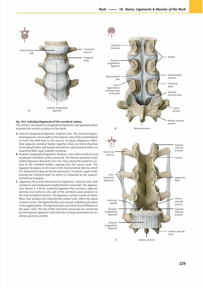
8/15/2019 Head and Neck Anatomy for Dental Medicine - Thieme; (January 26, 2010)
http://slidepdf.com/reader/full/head-and-neck-anatomy-for-dental-medicine-thieme-january-26-2010 242/384
Anterior longitudinalligament
Vertebralbody
Transverseprocess
A
Intervertebraldisk
Intervertebralforamen
Posteriorlongitudinal
ligament
Intervertebraldisk
Gap inligamentous
reinforcementof the disk
Spinous process
Inferior articularprocess
Costalprocess
Superiorarticular facet
Vertebralbody
Pedicle
Nutrientforamina
B
Facet jointcapsule
Posteriorlongitudinal
ligament
Anteriorlongitudinal
ligament
Spinous process
Inferior articularfacet
Superiorarticularprocess
Ligamentaflava
Lamina
C
Inter-transverseligaments
Superiorarticular
processTransverseprocess
Inferior
articularprocess
Fig. 10.6 Individual ligaments of the vertebral column
The anterior and posterior longitudinal ligaments and ligamenta flava
maintain the normal curvature of the spine.
A Anterior longitudinal ligament. Anterior view. The anterior longitu-
dinal ligament runs broadly on the anterior side of the vertebral bod-
ies from the skull base to the sacrum. Its deep collagenous fibers
bind adjacent vertebral bodies together (they are firmly attached
to vertebral bodies and loosely attached to intervertebral disks). Its
superficial fibers span multiple vertebrae.B Posterior longitudinal ligament. Posterior view with vertebral canal
windowed (vertebral arches removed). The thinner posterior longi-
tudinal ligament descends from the clivus along the posterior sur-
face of the vertebral bodies, passing into the sacral canal. The
ligament broadens at the level of the intervertebral disk (to which
it is attached by tapered lateral extensions). It narrows again while
passing the vertebral body (to which it is attached at the superior
and inferior margins).
C Ligamenta flava and intertransverse ligaments. Anterior view with
vertebral canal windowed (vertebral bodies removed). The ligamen-
tum flavum is a thick, powerful ligament that connects adjacent
laminae and reinforces the wall of the vertebral canal posterior to
the intervertebral foramina. The ligament consists mainly of elastic
fibers that produce the characteristic yellow color. When the spinal
column is erect, the ligamenta flava are tensed, stabilizing the spinein the sagittal plane. The ligamenta flava also limit forward flexion of
the spine. Note: The tips of the transverse processes are connected
by interspinous ligaments that limit the rocking movements of ver-
tebrae upon one another.
229
Neck 10. Bones, Ligaments & Muscles of the Neck
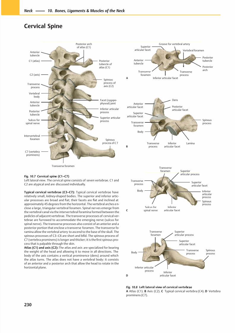
8/15/2019 Head and Neck Anatomy for Dental Medicine - Thieme; (January 26, 2010)
http://slidepdf.com/reader/full/head-and-neck-anatomy-for-dental-medicine-thieme-january-26-2010 243/384
Intervertebralforamen
Anteriortubercle
C1 (atlas)
C2 (axis)
Transverseprocess
Vertebralbody
Anteriortubercle
Posteriortubercle
Sulcus forspinal nerve
C7 (vertebraprominens)
Transverse foramen
Superior articularprocess
Inferior articularprocess
Facet (zygapo-physeal) joint
Spinousprocess ofaxis (C2)
Posterior archof atlas (C1)
Posteriortubercle of atlas (C1)
Spinousprocess of C 7
Superiorarticular facet
Anteriortubercle
Transverseforamen
Inferior articular facet
Transverseprocess
Posteriorarch
Posteriortubercle
Groove for vertebral artery
A
Vertebral foramen
Lamina
Anteriorarticular facet
Superior
articular facet
Transverseforamen
Body
Transverseprocess
Inferiorarticular facet
Spinousprocess
Posteriorarticular facet
Dens
B
Superior
articular process
Transverseprocess
Body
Sulcus forspinal nerve
Inferiorarticular facet
Inferiorarticularprocess
Spinousprocess
Superiorarticular facet
Transverseforamen
C
Body
Inferiorarticular facet
Inferior articularprocess
Spinousprocess
Transverseprocess
Superiorarticular facet
Superiorarticular process
Transverseforamen
D
Fig. 10.7 Cervical spine (C1–C7)
Left lateral view. The cervical spine consists of seven vertebrae. C1 and
C2 are atypical and are discussed individually.
Typical cervical vertebrae (C3–C7): Typical cervical vertebrae have
relatively small, kidney-shaped bodies. The superior and inferior artic-
ular processes are broad and flat; their facets are flat and inclined at
approximately 45 degrees from the horizontal. The vertebral arches en-
close a large, triangular vertebral foramen. Spinal ner ves emerge from
the vertebral canal via the intervertebral foramina formed between the
pedicles of adjacent vertebrae. The transverse processes of cervical ver-
tebrae are furrowed to accommodate the emerging nerve (sulcus for
spinal nerve). The transverse processes also consist of an anterior and a
posterior portion that enclose a transverse foramen. The transverse fo-
ramina allow the vertebral artery to ascend to the base of the skull. Thespinous processes of C3–C6 are short and bifid. The spinous process of
C7 (vertebra prominens) is longer and thicker; it is the first spinous pro-
cess that is palpable through the skin.
Atlas (C1) and axis (C2): The atlas and axis are specialized for bearing
the weight of the head and allowing it to move in all directions. The
body of the axis contains a vertical prominence (dens) around which
the atlas turns. The atlas does not have a vertebral body: it consists
of an anterior and a posterior arch that allow the head to rotate in the
horizontal plane.
Fig. 10.8 Left lateral view of cervical vertebrae
A Atlas (C1). B Axis (C2). C Typical cervical vertebra (C4). D Vertebraprominens (C7).
230
Neck 10. Bones, Ligaments & Muscles of the Neck
Cervical Spine
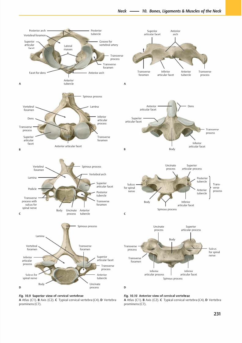
8/15/2019 Head and Neck Anatomy for Dental Medicine - Thieme; (January 26, 2010)
http://slidepdf.com/reader/full/head-and-neck-anatomy-for-dental-medicine-thieme-january-26-2010 244/384
Posterior arch
Superiorarticular
facet
Anterior arch
Anteriortubercle
Facet for dens
Lateralmasses
Transverse
processTransverseforamen
Groove forvertebral artery
Posteriortubercle
A
Vertebral foramen
Transverseprocess
Superiorarticular
facetAnterior articular facet
Dens
Transverseforamen
Vertebralforamen
Lamina
Spinous process
Inferior
articularprocess
B
Vertebralforamen
Lamina
Pedicle
Transverseprocess with
sulcus forspinal nerve
Body Anterior tubercle
Transverseforamen
Posteriortubercle
Superiorarticular facet
Vertebral arch
Spinous process
CUncinateprocess
Uncinateprocess
Vertebralforamen
Inferiorarticularprocess
Sulcus forspinal nerve
Body
Anteriortubercle
Transverseforamen
Transverseprocess
Superiorarticular facet
Lamina
Spinous process
D
Anteriorarch
Superiorarticular facet
Transverseforamen
Inferiorarticular facet
Anteriortubercle
Transverseprocess
A
Anteriorarticular facet
Superiorarticular facet
Body
Inferiorarticular facet
Transverseprocess
Dens
B
Uncinateprocess
Trans-verseprocess
Spinous process
Inferiorarticular facet
Anteriortubercle
Sulcusfor spinal
nerve
Posteriortubercle
Superiorarticular process
Body
C
Inferiorarticular process
Uncinateprocess
Transverseprocess
Transverseforamen
Spinous process
Inferiorarticular facet
Sulcusfor spinalnerve
Superiorarticular process
Body
D
Fig. 10.10 Anterior view of cervical vertebrae
A Atlas (C1). B Axis (C2). C Typical cervical vertebra (C4). D Vertebraprominens (C7).
Fig. 10.9 Superior view of cervical vertebrae
A Atlas (C1). B Axis (C2). C Typical cervical vertebra (C4). D Vertebraprominens (C7).
231
Neck 10. Bones, Ligaments & Muscles of the Neck
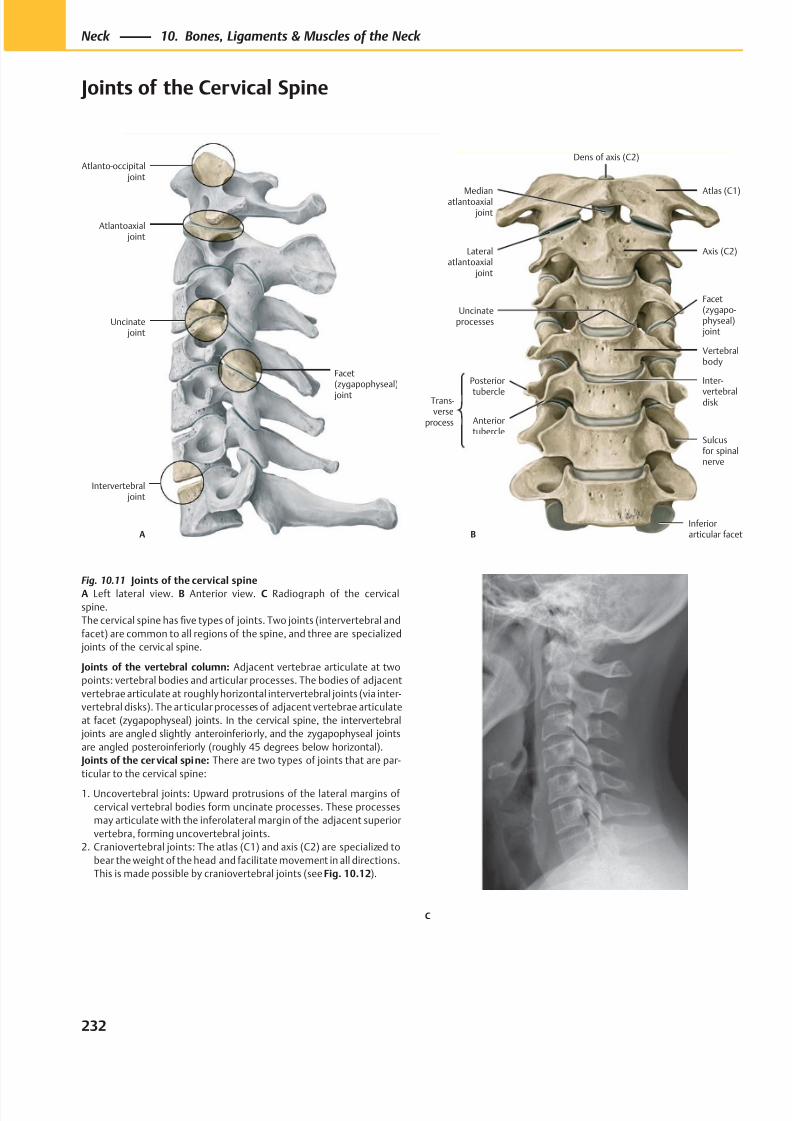
8/15/2019 Head and Neck Anatomy for Dental Medicine - Thieme; (January 26, 2010)
http://slidepdf.com/reader/full/head-and-neck-anatomy-for-dental-medicine-thieme-january-26-2010 245/384
Intervertebral joint
Facet(zygapophyseal)
joint
Atlantoaxial joint
Atlanto-occipital joint
Uncinate joint
A
Atlas (C1)Medianatlantoaxial
joint
Inferiorarticular facet
Sulcusfor spinalnerve
Inter-
vertebraldisk
Vertebralbody
Uncinateprocesses
Axis (C2)Lateralatlantoaxial
joint
B
Trans-verse
process
Posterior
tubercle
Anteriortubercle
Dens of axis (C2)
Facet(zygapo-physeal) joint
C
Fig. 10.11 Joints of the cervical spine
A Left lateral view. B Anterior view. C Radiograph of the cervical
spine.
The cervical spine has five types of joints. Two joints (intervertebral and
facet) are common to all regions of the spine, and three are specialized
joints of the cervical spine.
Joints of the vertebral column: Adjacent vertebrae articulate at two
points: vertebral bodies and articular processes. The bodies of adjacent
vertebrae articulate at roughly horizontal intervertebral joints (via inter-
vertebral disks). The articular processes of adjacent vertebrae articulate
at facet (zygapophyseal) joints. In the cervical spine, the intervertebral
joints are angled slightly anteroinferiorly, and the zygapophyseal joints
are angled posteroinferiorly (roughly 45 degrees below horizontal).
Joints of the cervical spine: There are two types of joints that are par-
ticular to the cervical spine:
1. Uncovertebral joints: Upward protrusions of the lateral margins of
cervical vertebral bodies form uncinate processes. These processes
may articulate with the inferolateral margin of the adjacent superior
vertebra, forming uncovertebral joints.
2. Craniovertebral joints: The atlas (C1) and axis (C2) are specialized to
bear the weight of the head and facilitate movement in all directions.
This is made possible by craniovertebral joints (see Fig. 10.12).
232
Neck 10. Bones, Ligaments & Muscles of the Neck
Joints of the Cervical Spine
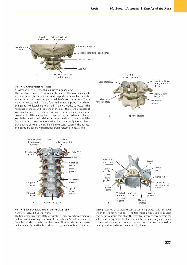
8/15/2019 Head and Neck Anatomy for Dental Medicine - Thieme; (January 26, 2010)
http://slidepdf.com/reader/full/head-and-neck-anatomy-for-dental-medicine-thieme-january-26-2010 246/384
Superiornuchal line
Lateral massof atlas
Dens of axis (C2)
Occipital condyle (occipital bone)
External occipitalprotuberance
Axis (C2)
Foramen magnum
Posterior arch of atlas(with tubercle)
A
Groove forvertebral artery
Spinous process
Transverseprocess
Medianatlantoaxial joint
Superior articularfacet (lateral massof axis)
Lateral atlanto-axial joint
Dens of axis (C2)
B
A
C1 spinalnerve
Vertebral arteryin transverse
foramen
C5 spinal
nerve
C7 spinalnerve
Vertebral body (C7)
Spinalnerve insulcus
Transverseprocess
Uncinateprocess
Vertebralartery
Axis (C2)
Atlas (C1)
Dens Lateralatlantoaxial joint
Dorsal ramus
Ventralramus
Ventralroot
Spinal cordin vertebral
foramen
Superiorarticular
facet
Spinalganglion
Vertebralartery in
transverseforamen
Vertebralbody
Uncinateprocess
Transverseprocess
B
Dorsalroot
White and gray
rami communi-cantes
Fig. 10.12 Craniovertebral joints
A Posterior view. B Left oblique posterosuperior view.
There are five craniovertebral joints. The paired atlanto-occipital jointsare articulations between the concave superior articular facets of the
atlas (C1) and the convex occipital condyle of the occipital bone. These
allow the head to rock back and forth in the sagittal plane. The atlanto-
axial joints (two lateral and one medial) allow the atlas to rotate in the
horizontal plane around the dens of the axis. The lateral atlantoaxial
joints are the paired articulations between the inferior and superior ar-
ticular facets of the atlas and axis, respectively. The median atlantoaxial
joint is the unpaired articulation between the dens of the axis and the
fovea of the atlas. Note: While only the atlanto-occipital joints are direct
articulations between the cranium and vertebral column, the atlanto-
axial joints are generally classified as craniovertebral joints as well.
Fig. 10.13 Neurovasculature of the cervical spine
A Anterior view. B Superior view.
The transverse processes of the cervical vertebrae are extremely impor-
tant in communicating neurovascular structures. Spinal nerves arise
from the spinal cord in the vertebral canal. They exit via the interverte-
bral foramina formed by the pedicles of adjacent vertebrae. The trans-
verse processes of cervical vertebrae contain grooves (sulci) through
which the spinal nerves pass. The transverse processes also contain
transverse foramina that allow the vertebral artery to ascend from the
subclavian artery and enter the skull via the foramen magnum. Injury
to the cervical spine can compress the neurovascular structures as they
emerge and ascend from the vertebral column.
233
Neck 10. Bones, Ligaments & Muscles of the Neck
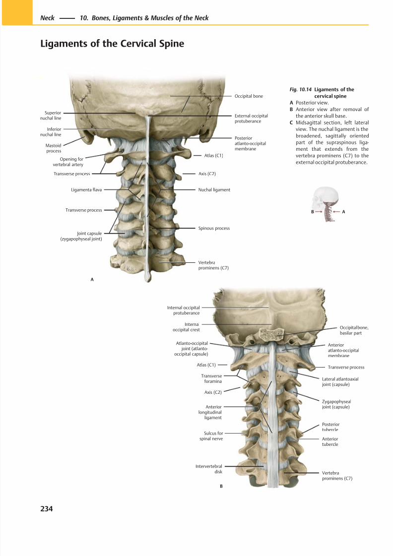
8/15/2019 Head and Neck Anatomy for Dental Medicine - Thieme; (January 26, 2010)
http://slidepdf.com/reader/full/head-and-neck-anatomy-for-dental-medicine-thieme-january-26-2010 247/384
Intervertebraldisk
Atlanto-occipital joint (atlanto-
occipital capsule)
Atlas (C1)
Transverseforamina
Axis (C2)
Anteriorlongitudinal
ligament
Vertebraprominens (C7)
Zygapophyseal joint (capsule)
Lateral atlantoaxial joint (capsule)
Transverse process
Anterioratlanto-occipitalmembrane
Occipital bone,basilar part
Internaloccipital crest
Internal occipitalprotuberance
B
Anteriortubercle
Posteriortubercle
Sulcus forspinal nerve
Superiornuchal line
Inferiornuchal line
Mastoidprocess
Opening forvertebral artery
Ligamenta flava
Transverse process
Joint capsule(zygapophyseal joint)
Vertebraprominens (C7)
Spinous process
Nuchal ligament
Atlas (C1)
Posterioratlanto-occipitalmembrane
Occipital bone
External occipitalprotuberance
Transverse process Axis (C2)
A
AB
Fig. 10.14 Ligaments of the
cervical spineA Posterior view.
B Anterior view after removal of
the anterior skull base.
C Midsagittal section, left lateral
view. The nuchal ligament is the
broadened, sagittally oriented
part of the supraspinous liga-
ment that extends from the
vertebra prominens (C7) to the
external occipital protuberance.
234
Neck 10. Bones, Ligaments & Muscles of the Neck
Ligaments of the Cervical Spine
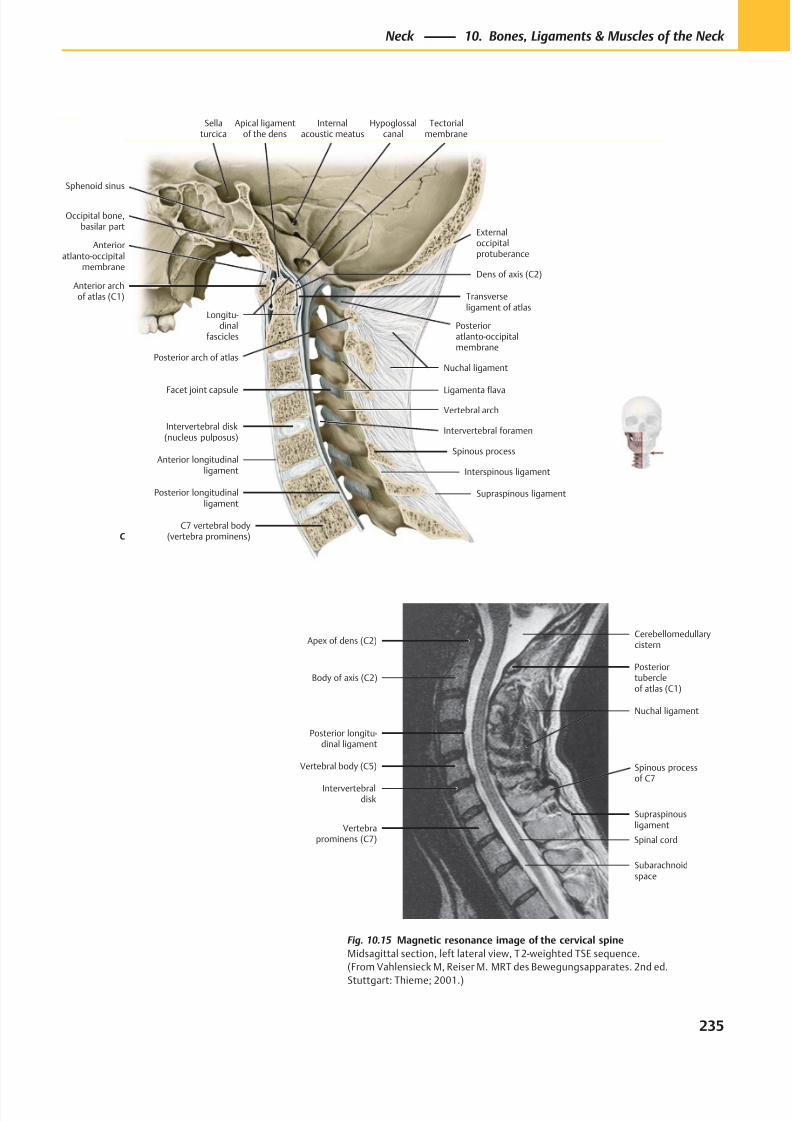
8/15/2019 Head and Neck Anatomy for Dental Medicine - Thieme; (January 26, 2010)
http://slidepdf.com/reader/full/head-and-neck-anatomy-for-dental-medicine-thieme-january-26-2010 248/384
Posterioratlanto-occipitalmembrane
Sphenoid sinus
Internalacoustic meatus
Occipital bone,basilar part
Apical ligamentof the dens
Anterior archof atlas (C1)
Dens of axis (C2)
Transverseligament of atlas
Intervertebral disk(nucleus pulposus)
Anterior longitudinalligament
Posterior longitudinalligament
C7 vertebral body(vertebra prominens)
Supraspinous ligament
Interspinous ligament
Spinous process
Ligamenta flava
Vertebral arch
Facet joint capsule
Nuchal ligamentPosterior arch of atlas
Externaloccipitalprotuberance
Tectorialmembrane
Longitu-dinal
fascicles
Hypoglossalcanal
Sellaturcica
Anterioratlanto-occipital
membrane
Intervertebral foramen
C
Apex of dens (C2)
Posterior longitu-dinal ligament
Vertebral body (C5)
Intervertebraldisk
Vertebraprominens (C7)
Subarachnoidspace
Supraspinousligament
Posteriortubercleof atlas (C1)
Cerebellomedullarycistern
Nuchal ligament
Spinal cord
Body of axis (C2)
Spinous processof C7
Fig. 10.15 Magnetic resonance image of the cervical spine
Midsagittal section, left lateral view, T 2-weighted TSE sequence.
(From Vahlensieck M, Reiser M. MRT des Bewegungsapparates. 2nd ed.
Stuttgart: Thieme; 2001.)
235
Neck 10. Bones, Ligaments & Muscles of the Neck
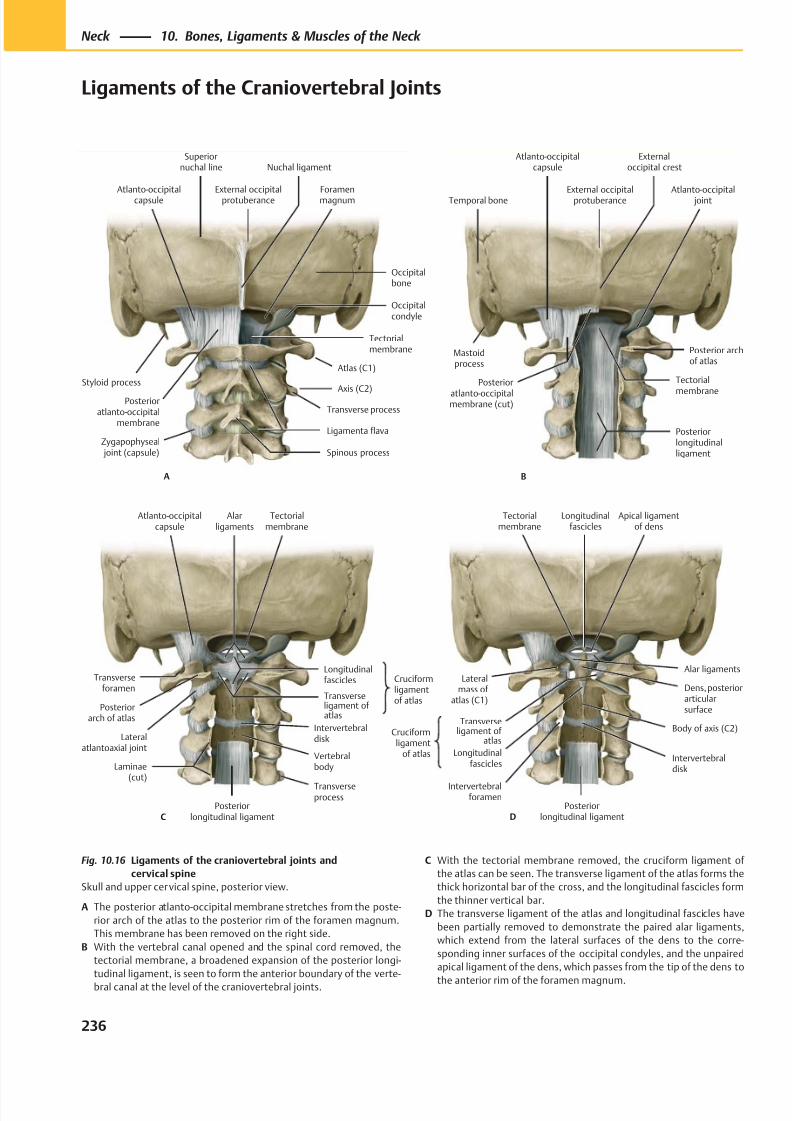
8/15/2019 Head and Neck Anatomy for Dental Medicine - Thieme; (January 26, 2010)
http://slidepdf.com/reader/full/head-and-neck-anatomy-for-dental-medicine-thieme-january-26-2010 249/384
Spinous process
Superiornuchal line
Styloid process
Posterioratlanto-occipital
membrane
Atlanto-occipitalcapsule
Ligamenta flava
Axis (C2)
Tectorialmembrane
Foramenmagnum
Occipitalcondyle
Nuchal ligament
Occipitalbone
External occipitalprotuberance
A
Zygapophyseal joint (capsule)
Atlas (C1)
Transverse process
Temporal bone
Atlanto-occipitalcapsule
Posterior
atlanto-occipitalmembrane (cut)
Posteriorlongitudinalligament
Tectorial
membrane
Posterior archof atlas
Atlanto-occipital joint
Externaloccipital crest
External occipitalprotuberance
B
Mastoidprocess
Tectorialmembrane
Atlanto-occipitalcapsule
Transverseforamen
Posteriorarch of atlas
Lateralatlantoaxial joint
Laminae(cut)
Posteriorlongitudinal ligament
Transverseprocess
Vertebralbody
Intervertebraldisk
Cruciformligamentof atlas
Transverseligament ofatlas
Longitudinalfascicles
Alarligaments
C
Cruciformligament
of atlas
Tectorialmembrane
Lateralmass of
atlas (C1)
Body of axis (C2)
Intervertebralforamen
Posteriorlongitudinal ligament
Intervertebraldisk
Transverseligament of
atlas
Dens, posteriorarticularsurface
Alar ligaments
Apical ligamentof dens
Longitudinalfascicles
D
Longitudinalfascicles
Fig. 10.16 Ligaments of the craniovertebral joints and
cervical spine
Skull and upper cervical spine, posterior view.
A The posterior atlanto-occipital membrane stretches from the poste-
rior arch of the atlas to the posterior rim of the foramen magnum.
This membrane has been removed on the right side.
B With the vertebral canal opened and the spinal cord removed, the
tectorial membrane, a broadened expansion of the posterior longi-
tudinal ligament, is seen to form the anterior boundary of the verte-
bral canal at the level of the craniovertebral joints.
C With the tectorial membrane removed, the cruciform ligament of
the atlas can be seen. The transverse ligament of the atlas forms the
thick horizontal bar of the cross, and the longitudinal fascicles form
the thinner vertical bar.
D The transverse ligament of the atlas and longitudinal fascicles have
been partially removed to demonstrate the paired alar ligaments,
which extend from the lateral surfaces of the dens to the corre-
sponding inner surfaces of the occipital condyles, and the unpaired
apical ligament of the dens, which passes from the tip of the dens to
the anterior rim of the foramen magnum.
236
Neck 10. Bones, Ligaments & Muscles of the Neck
Ligaments of the Craniovertebral Joints
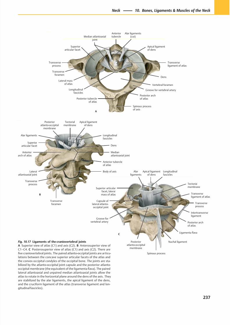
8/15/2019 Head and Neck Anatomy for Dental Medicine - Thieme; (January 26, 2010)
http://slidepdf.com/reader/full/head-and-neck-anatomy-for-dental-medicine-thieme-january-26-2010 250/384
B
Posterioratlanto-occipital
membrane
Longitudinalfascicles
Tectorialmembrane
Superiorarticular facet
Anteriorarch of atlas
Medianatlantoaxial joint
Lateralatlantoaxial joint
Transverseprocess
Transverseforamen
Body of axis
Anterior tubercleof atlas
Dens
Alar ligaments
Apical ligamentof dens
Transverseprocess
Transverseforamen
Lateral massof atlas
Posterior archof atlasPosterior tubercle
of atlas
Spinous processof axis
Vertebral foramen
Superiorarticular facet
Dens
Transverseligament of atlas
Apical ligamentof dens
Alar ligaments(cut)
Anteriortubercle
Longitudinalfascicles
Median atlantoaxial joint
Groove for vertebral artery
A
Longitudinalfascicles
Capsule of lateral atlanto-occipital joint
Groove forvertebral artery
Spinous process
Nuchal ligament
Posterior archof atlas
Intertransverseligament
Transverseprocess
Posterioratlanto-occipital
membrane
Transverseligament of atlas
Tectorialmembrane
Alarligaments
Apical ligamentof dens
C
Superior articularfacet, lateral
mass of atlas
Ligamenta flava
Fig. 10.17 Ligaments of the craniovertebral joints
A Superior view of atlas (C1) and axis (C2). B Anterosuperior view of
C1–C4. C Posterosuperior view of atlas (C1) and axis (C2). There are
five craniovertebral joints. The paired atlanto-occipital joints are articu-
lations between the concave superior articular facets of the atlas and
the convex occipital condyles of the occipital bone. The joints are sta-
bilized by the atlanto-occipital joint capsule and the posterior atlanto-
occipital membrane (the equivalent of the ligamenta flava). The paired
lateral atlantoaxial and unpaired median atlantoaxial joints allow the
atlas to rotate in the horizontal plane around the dens of the axis. They
are stabilized by the alar ligaments, the apical ligament of the dens,
and the cruciform ligament of the atlas (transverse ligament and lon-gitudinal fascicles).
237
Neck 10. Bones, Ligaments & Muscles of the Neck
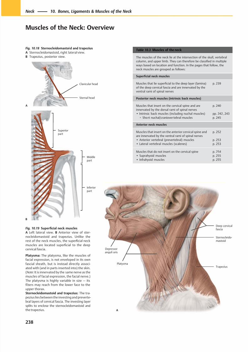
8/15/2019 Head and Neck Anatomy for Dental Medicine - Thieme; (January 26, 2010)
http://slidepdf.com/reader/full/head-and-neck-anatomy-for-dental-medicine-thieme-january-26-2010 251/384
Trapezius
Sternocleido-mastoid
Depressoranguli oris
Platysma
Deep cervicalfascia
A
Sternal head
Clavicular head
A
B
Superiorpart
Middlepart
Inferiorpart
Table 10.3 Muscles of the neck
The muscles of the neck lie at the intersection of the skull, vertebral
column, and upper limb. They can therefore be classified in multipleways based on location and function. In the pages that follow, the
neck muscles are grouped as follows:
Superficial neck muscles
Muscles that lie superficial to the deep layer (lamina)
of the deep cervical fascia and are innervated by the
ventral rami of spinal nerves
p. 239
Posterior neck muscles (intrinsic back muscles)
Muscles that insert on the cervical spine and are
innervated by the dorsal rami of spinal nerves
• Intrinsic back muscles (including nuchal muscles)
◦ Short nuchal/craniover tebral muscles
p. 240
pp. 242, 243
p. 245
Anterior neck muscles
Muscles that insert on the anterior cervical spine and
are innervated by the ventral rami of spinal nerves
• Anterior vertebral (prevertebral) muscles
• Lateral vertebral muscles (scalenes)
p. 252
p. 253
p. 253
Muscles that do not insert on the cervical spine
• Suprahyoid muscles
• Infrahyoid muscles
p. 254
p. 255
p. 255
Fig. 10.18 Sternocleidomastoid and trapezius
A Sternocleidomastoid, right lateral view.
B Trapezius, posterior view.
Fig. 10.19 Superficial neck muscles
A Left lateral view. B Anterior view of ster-
nocleidomastoid and trapezius. Unlike the
rest of the neck muscles, the superficial neck
muscles are located superfi
cial to the deepcervical fascia.
Platysma: The platysma, like the muscles of
facial expression, is not enveloped in its own
fascial sheath, but is instead directly associ-
ated with (and in parts inserted into) the skin.
(Note: It is innervated by the same nerve as the
muscles of facial expression, the facial nerve.)
The platysma is highly variable in size — its
fibers may reach from the lower face to the
upper thorax.
Sternocleidomastoid and trapezius: The tra-
pezius lies between the investing and preverte-
bral layers of cervical fascia. The investing layer
splits to enclose the sternocleidomastoid and
the trapezius.
238
Neck 10. Bones, Ligaments & Muscles of the Neck
Muscles of the Neck: Overview
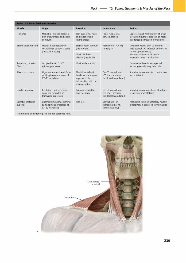
8/15/2019 Head and Neck Anatomy for Dental Medicine - Thieme; (January 26, 2010)
http://slidepdf.com/reader/full/head-and-neck-anatomy-for-dental-medicine-thieme-january-26-2010 252/384
Trapezius
Sternocleido-
mastoid
B
Table 10.4 Superficial neck muscles
Muscle Origin Insertion Innervation Action
Platysma Mandible (inferior border);
skin of lower face and angle
of mouth
Skin over lower neck
and superior and
lateral thorax
Facial n. (CN VII),
cervical branch
Depresses and wrinkles skin of lower
face and mouth; tenses skin of neck;
aids forced depression of mandible
Sternocleidomastoid Occipital bone (superiornuchal line); temporal bone
(mastoid process)
Sternal head: sternum(manubrium)
Accessory n. (CN IX),spinal part
Unilateral: Moves chin up and out(tilts occiput to same side and rotates
face to opposite side)
Bilateral: Extends head; aids in
respiration when head is fixed
Clavicular head:
clavicle (medial⅓)
Trapezius, superior
fibers*
Occipital bone; C1–C7
spinous processes
Clavicle (lateral⅓) Draws scapula obliquely upward;
rotates glenoid cavity inferiorly
Rhomboid minor Ligamentum nuchae (infer ior
part); spinous processes of
C7–T1 vertebrae
Medial (vertebral)
border of the scapula,
superior to the
intersection with the
scapular spine
C4–C5 ventral rami
(C5 fibers are from
the dorsal scapular n.)
Scapular movements (e.g., retraction
and rotation)
Levator scapulae C1–C4 cerv ical vertebrae;
posterior tubercles of
transverse processes
Scapula, medial to
superior angle
C3–C5 ventral rami
(C5 fibers are from
the dorsal scapular n.)
Scapular movements (e.g., elevation,
retraction, and rotation)
Serratus posterior
superior
Ligamentum nuchae (inferior
part); spinous processes of
C7–T3 vertebrae
Ribs 2–5 Ventral rami of
thoracic spinal nn.
(intercostal nn.)
Postulated to be an accessory muscle
of respiration; assists in elevating ribs
*The middle and inferior parts are not described here.
239
Neck 10. Bones, Ligaments & Muscles of the Neck
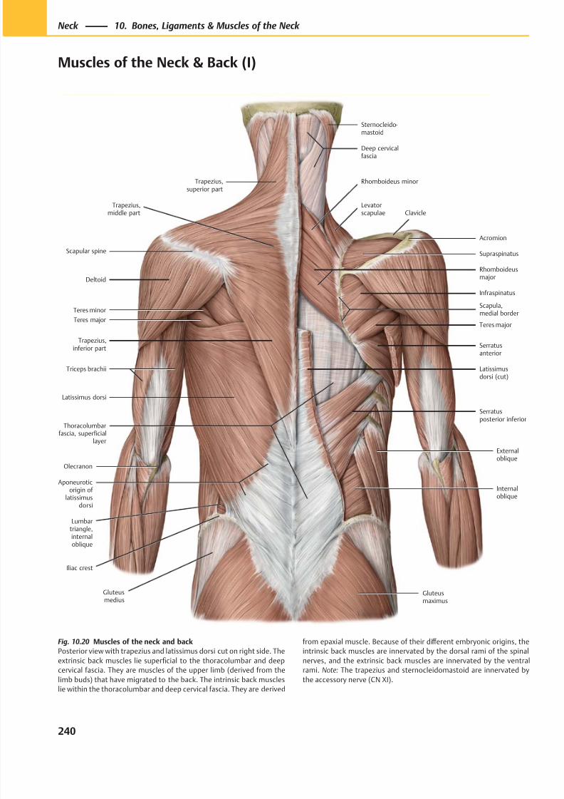
8/15/2019 Head and Neck Anatomy for Dental Medicine - Thieme; (January 26, 2010)
http://slidepdf.com/reader/full/head-and-neck-anatomy-for-dental-medicine-thieme-january-26-2010 253/384
Lumbartriangle,internaloblique
Trapezius,superior part
Trapezius,middle part
Trapezius,inferior part
Scapular spine
Deltoid
Teres major
Latissimus dorsi
Triceps brachii
Olecranon
Iliac crest
Gluteusmedius
Gluteusmaximus
Thoracolumbarfascia, superficial
layer
Serratus
posterior inferior
Serratusanterior
Teres major
Infraspinatus
Scapula,medial border
Supraspinatus
Clavicle
Rhomboideus
major
Levatorscapulae
Rhomboideus minor
Sternocleido-mastoid
Deep cervicalfascia
Externaloblique
Internaloblique
Latissimusdorsi (cut)
Acromion
Aponeuroticorigin of
latissimusdorsi
Teres minor
Fig. 10.20 Muscles of the neck and back
Posterior view with trapezius and latissimus dorsi cut on right side. The
extrinsic back muscles lie superficial to the thoracolumbar and deep
cervical fascia. They are muscles of the upper limb (derived from the
limb buds) that have migrated to the back. The intrinsic back muscles
lie within the thoracolumbar and deep cervical fascia. They are derived
from epaxial muscle. Because of their diff erent embryonic origins, the
intrinsic back muscles are innervated by the dorsal rami of the spinal
nerves, and the extrinsic back muscles are innervated by the ventral
rami. Note: The trapezius and sternocleidomastoid are innervated by
the accessory nerve (CN XI).
240
Neck 10. Bones, Ligaments & Muscles of the Neck
Muscles of the Neck & Back (I)
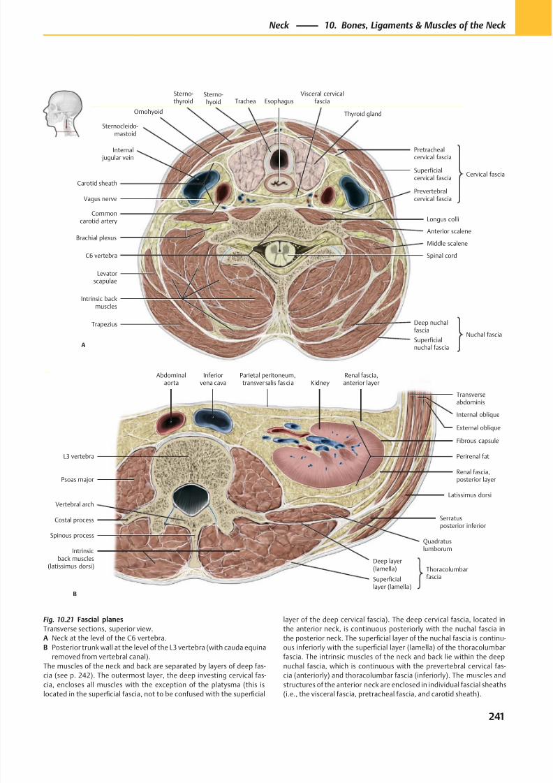
8/15/2019 Head and Neck Anatomy for Dental Medicine - Thieme; (January 26, 2010)
http://slidepdf.com/reader/full/head-and-neck-anatomy-for-dental-medicine-thieme-january-26-2010 254/384
A
Carotid sheath
Sternocleido-
mastoid
Internal jugular vein
Commoncarotid artery
Levatorscapulae
Superficialnuchal fascia
Deep nuchalfascia
Nuchal fascia
Intrinsic backmuscles
Middle scalene
Prevertebralcervical fascia
Pretrachealcervical fascia
Superficialcervical fascia
Cervical fascia
Thyroid gland
Visceral cervicalfascia
Sterno-thyroid
Trapezius
Vagus nerve
EsophagusTrachea
Brachial plexus
C6 vertebra Spinal cord
Longus colli
Omohyoid
Sterno-hyoid
Anterior scalene
Intrinsicback muscles
(latissimus dorsi)
B
Quadratus
lumborum
Serratusposterior inferior
Latissimus dorsi
Renal fascia,posterior layer
Perirenal fat
Fibrous capsule
Internal oblique
Renal fascia,anterior layer
Parietal peritoneum,transversalis fascia K idney
Inferiorvena cava
Abdominalaorta
Psoas major
L3 vertebra
Costal process
Vertebral arch
Spinous process
Superficiallayer (lamella)
Deep layer(lamella) Thoracolumbar
fascia
Transverseabdominis
External oblique
Fig. 10.21 Fascial planes
Transverse sections, superior view.
A Neck at the level of the C6 vertebra.
B Posterior trunk wall at the level of the L3 vertebra (with cauda equina
removed from vertebral canal).
The muscles of the neck and back are separated by layers of deep fas-
cia (see p. 242). The outermost layer, the deep investing cervical fas-
cia, encloses all muscles with the exception of the platysma (this islocated in the superficial fascia, not to be confused with the superficial
layer of the deep cervical fascia). The deep cervical fascia, located in
the anterior neck, is continuous posteriorly with the nuchal fascia in
the posterior neck. The superficial layer of the nuchal fascia is continu-
ous inferiorly with the superficial layer (lamella) of the thoracolumbar
fascia. The intrinsic muscles of the neck and back lie within the deep
nuchal fascia, which is continuous with the prevertebral cervical fas-
cia (anteriorly) and thoracolumbar fascia (inferiorly). The muscles and
structures of the anterior neck are enclosed in individual fascial sheaths(i.e., the visceral fascia, pretracheal fascia, and carotid sheath).
241
Neck 10. Bones, Ligaments & Muscles of the Neck
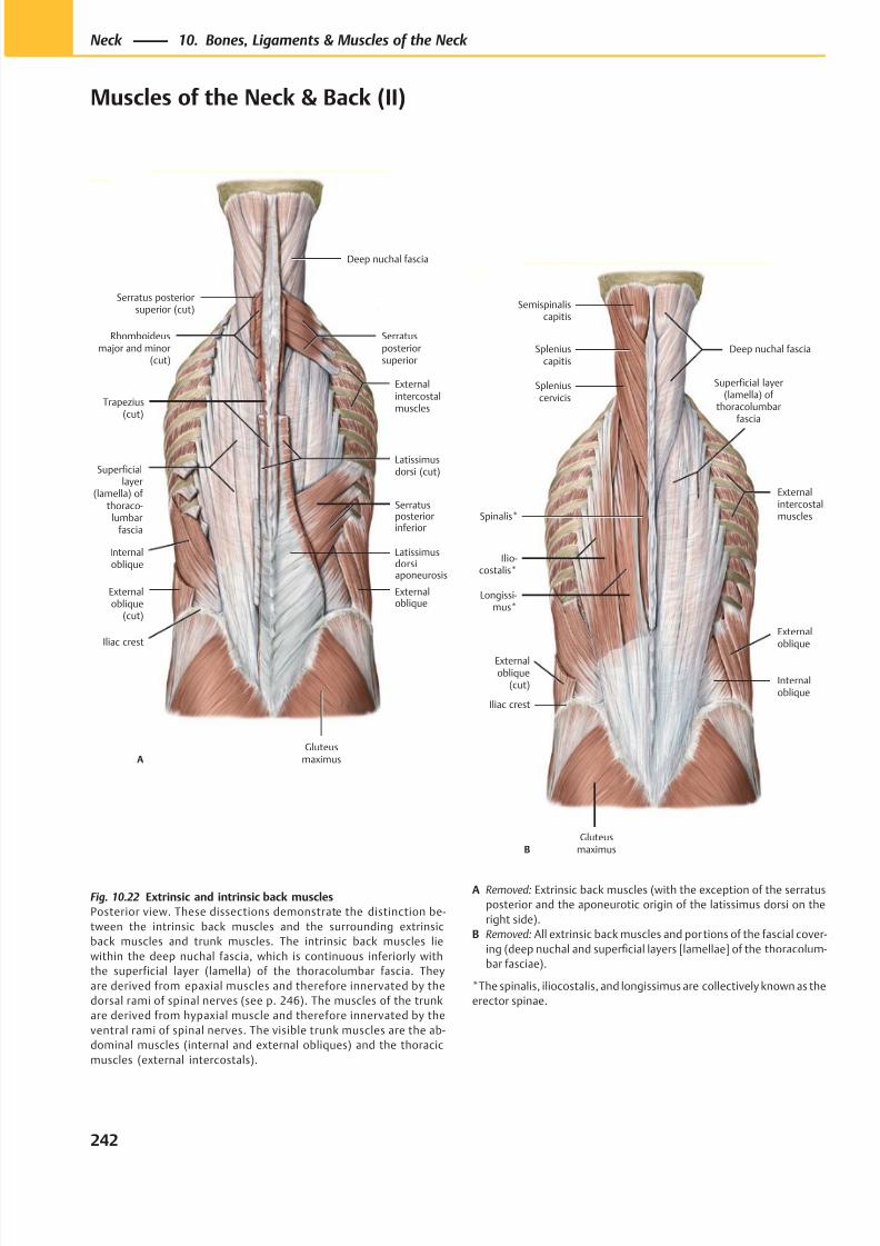
8/15/2019 Head and Neck Anatomy for Dental Medicine - Thieme; (January 26, 2010)
http://slidepdf.com/reader/full/head-and-neck-anatomy-for-dental-medicine-thieme-january-26-2010 255/384
Deep nuchal fascia
Internaloblique
Externaloblique
(cut)
Gluteusmaximus
Superficiallayer
(lamella) of thoraco-
lumbarfascia
Latissimusdorsiaponeurosis
Externaloblique
Serratusposteriorinferior
Trapezius(cut)
Serratusposteriorsuperior
Rhomboideusmajor and minor
(cut)
Iliac crest
Externalintercostalmuscles
Serratus posteriorsuperior (cut)
A
Latissimusdorsi (cut)
Semispinaliscapitis
Spleniuscapitis
Spleniuscervicis
Spinalis*
Ilio-costalis*
Longissi-mus*
Gluteusmaximus
Internaloblique
Externaloblique
Deep nuchal fascia
Iliac crest
Externalintercostalmuscles
Externaloblique
(cut)
Superficial layer(lamella) of
thoracolumbarfascia
B
Fig. 10.22 Extrinsic and intrinsic back muscles
Posterior view. These dissections demonstrate the distinction be-
tween the intrinsic back muscles and the surrounding extrinsic
back muscles and trunk muscles. The intrinsic back muscles lie
within the deep nuchal fascia, which is continuous inferiorly with
the superficial layer (lamella) of the thoracolumbar fascia. They
are derived from epaxial muscles and therefore innervated by the
dorsal rami of spinal nerves (see p. 246). The muscles of the trunk
are derived from hypaxial muscle and therefore innervated by the
ventral rami of spinal nerves. The visible trunk muscles are the ab-
dominal muscles (internal and external obliques) and the thoracic
muscles (external intercostals).
A Removed: Extrinsic back muscles (with the exception of the serratus
posterior and the aponeurotic origin of the latissimus dorsi on the
right side).
B Removed: All extrinsic back muscles and portions of the fascial cover-
ing (deep nuchal and superficial layers [lamellae] of the thoracolum-
bar fasciae).
*The spinalis, iliocostalis, and longissimus are collectively known as the
erector spinae.
242
Neck 10. Bones, Ligaments & Muscles of the Neck
Muscles of the Neck & Back (II)
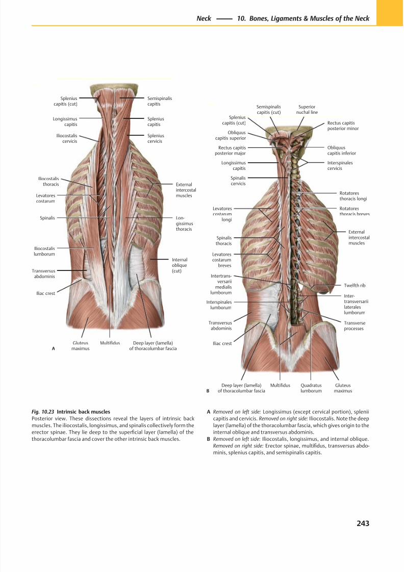
8/15/2019 Head and Neck Anatomy for Dental Medicine - Thieme; (January 26, 2010)
http://slidepdf.com/reader/full/head-and-neck-anatomy-for-dental-medicine-thieme-january-26-2010 256/384
Spleniuscapitis (cut)
Longissimuscapitis
Iliocostaliscervicis
Externalintercostalmuscles
Iliocostalisthoracis
Levatores
costarum
Spinalis
Iliocostalislumborum
Transversusabdominis
Gluteusmaximus
Multifidus
Lon-gissimusthoracis
Spleniuscervicis
Spleniuscapitis
Semispinaliscapitis
Iliac crest
Deep layer (lamella)of thoracolumbar fascia
Internaloblique(cut)
A
Quadratuslumborum
Spleniuscapitis (cut)
Obliquuscapitis superior
Rectus capitisposterior major
Longissimuscapitis
Semispinaliscapitis (cut)
Spinaliscervicis
Externalintercostalmuscles
Levatorescostarum
longi
Levatorescostarum
breves
Spinalisthoracis
Deep layer (lamella)of thoracolumbar fascia
Iliac crest
Gluteusmaximus
Multifidus
Interspinaleslumborum
Intertrans-versarii
medialislumborum
Transversusabdominis
Inter-
transversariilateraleslumborum
Rotatoresthoracis breves
Rotatores
thoracis longi
Superiornuchal line
Twelfth rib
Transverseprocesses
Interspinalescervicis
Obliquuscapitis inferior
Rectus capitisposterior minor
B
Fig. 10.23 Intrinsic back muscles
Posterior view. These dissections reveal the layers of intrinsic back
muscles. The iliocostalis, longissimus, and spinalis collectively form the
erector spinae. They lie deep to the superficial layer (lamella) of the
thoracolumbar fascia and cover the other intrinsic back muscles.
A Removed on left side: Longissimus (except cervical portion), splenii
capitis and cervicis. Removed on right side: Iliocostalis. Note the deep
layer (lamella) of the thoracolumbar fascia, which gives origin to the
internal oblique and transversus abdominis.
B Removed on left side: Iliocostalis, longissimus, and internal oblique.
Removed on right side: Erector spinae, multifidus, transversus abdo-
minis, splenius capitis, and semispinalis capitis.
243
Neck 10. Bones, Ligaments & Muscles of the Neck
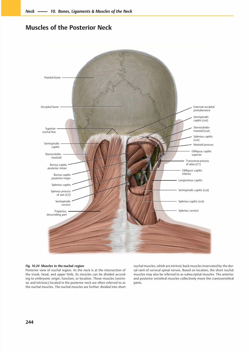
8/15/2019 Head and Neck Anatomy for Dental Medicine - Thieme; (January 26, 2010)
http://slidepdf.com/reader/full/head-and-neck-anatomy-for-dental-medicine-thieme-january-26-2010 257/384
Splenius capitis (cut)
Splenius cervicis
Semispinaliscervicis
Semispinalis capitis (cut)
Longissimus capitis
Obliquus capitisinferiorRectus capitis
posterior major
Rectus capitisposterior minor
Obliquus capitissuperior
Mastoid process
Splenius capitis(cut)
Semispinaliscapitis (cut)
Transverse processof atlas (C1)
Spinous processof axis (C2)
Parietal bone
External occipitalprotuberance
Superiornuchal line
Semispinaliscapitis
Sternocleido-mastoid
Splenius capitis
Trapezius,descending part
Occipital bone
Sternocleido-mastoid (cut)
Fig. 10.24 Muscles in the nuchal region
Posterior view of nuchal region. As the neck is at the intersection of
the trunk, head, and upper limb, its muscles can be divided accord-
ing to embryonic origin, function, or location. Those muscles (extrin-
sic and intrinsic) located in the posterior neck are often referred to as
the nuchal muscles. The nuchal muscles are further divided into short
nuchal muscles, which are intrinsic back muscles innervated by the dor-
sal rami of cervical spinal nerves. Based on location, the short nuchal
muscles may also be referred to as suboccipital muscles. The anterior
and posterior vertebral muscles collectively move the craniovertebral
joints.
244
Neck 10. Bones, Ligaments & Muscles of the Neck
Muscles of the Posterior Neck
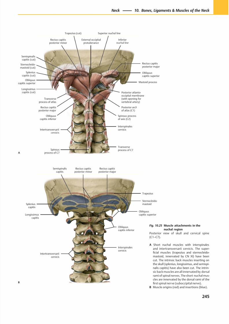
8/15/2019 Head and Neck Anatomy for Dental Medicine - Thieme; (January 26, 2010)
http://slidepdf.com/reader/full/head-and-neck-anatomy-for-dental-medicine-thieme-january-26-2010 258/384
Longissimuscapitis
Spleniuscapitis
Semispinaliscapitis
Interspinalescervicis
Obliquuscapitis inferior
Rectus capitisposterior major
Obliquuscapitis superior
Sternocleido-mastoid
Trapezius
Rectus capitisposterior minor
Intertransversariicervicis
B
Transverseprocess of atlas
Trapezius (cut)
Sternocleido-mastoid (cut)
External occipitalprotuberance
Rectus capitisposterior minor
Semispinaliscapitis (cut)
Obliquuscapitis superior
Spleniuscapitis (cut)
Longissimuscapitis (cut)
Rectus capitisposterior major
Obliquuscapitis inferior
Spinous processof axis (C2)
Intertransversariicervicis
Spinousprocess of C7
Interspinalescervicis
Rectus capitisposterior major
Posterior archof atlas (C1)
Posterior atlanto-occipital membrane(with opening forvertebral artery)
Mastoid process
Obliquuscapitis superior
Inferiornuchal line
Superior nuchal line
Transverseprocess of C7
A
Fig. 10.25 Muscle attachments in thenuchal region
Posterior view of skull and cervical spine
(C1–C7).
A Short nuchal muscles with interspinales
and intertransversarii cervicis. The super-
ficial muscles (trapezius and sternocleido-
mastoid, innervated by CN XI) have been
cut. The intrinsic back muscles inserting on
the skull (splenius, longissimus, and semispi-
nalis capitis) have also been cut. The intrin-
sic back muscles are all innervated by dorsal
rami of spinal nerves. The short nuchal mus-
cles are innervated by the dorsal rami of the
first spinal nerve (suboccipital nerve).B Muscle origins (red) and insertions (blue).
245
Neck 10. Bones, Ligaments & Muscles of the Neck
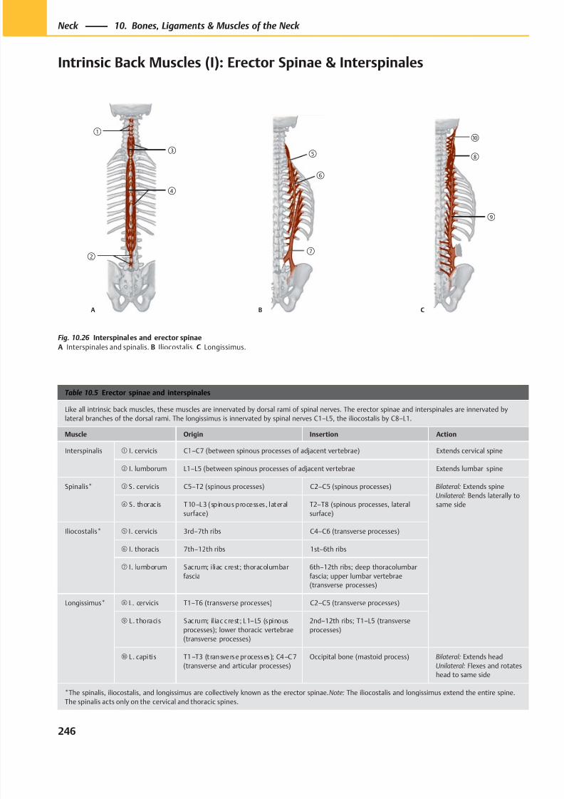
8/15/2019 Head and Neck Anatomy for Dental Medicine - Thieme; (January 26, 2010)
http://slidepdf.com/reader/full/head-and-neck-anatomy-for-dental-medicine-thieme-january-26-2010 259/384
①
②
④
③
A
⑤
⑥
⑦
B
⑩
⑨
⑧
C
Table 10.5 Erector spinae and interspinales
Like all intrinsic back muscles, these muscles are innervated by dorsal rami of spinal nerves. The erector spinae and interspinales are innervated by
lateral branches of the dorsal rami. The longissimus is innervated by spinal nerves C1–L5, the iliocostalis by C8–L1.
Muscle Origin Insertion Action
Interspinalis ① I. cervicis C1–C7 (between spinous processes of adjacent vertebrae) Extends cervical spine
② I. lumborum L1–L5 (between spinous processes of adjacent vertebrae Extends lumbar spine
Spinalis* ③ S. cervicis C5–T2 (spinous processes) C2–C5 (spinous processes) Bilateral: Extends spine
Unilateral: Bends laterally to
same side④ S. thoracis T10–L3 (spinous processes, lateral
surface)
T2–T8 (spinous processes, lateral
surface)
Iliocostalis* ⑤ I. cervicis 3rd–7th ribs C4–C6 (transverse processes)
⑥ I. thoracis 7th–12th ribs 1st–6th ribs
⑦ I. lumborum Sacrum; iliac crest; thoracolumbar
fascia
6th–12th ribs; deep thoracolumbar
fascia; upper lumbar vertebrae
(transverse processes)
Longissimus* ⑧ L. cervicis T1–T6 (transverse processes) C2–C5 (transverse processes)
⑨ L . thoracis Sacrum; il iac crest; L1–L5 (spinous
processes); lower thoracic vertebrae
(transverse processes)
2nd–12th ribs; T1–L5 (transverse
processes)
⑩ L . capitis T1–T3 (transverse processes); C4–C7
(transverse and articular processes)
Occipital bone (mastoid process) Bilateral: Extends head
Unilateral: Flexes and rotates
head to same side
*The spinalis, iliocostalis, and longissimus are collectively known as the erector spinae. Note: The iliocostalis and longissimus extend the entire spine.
The spinalis acts only on the cervical and thoracic spines.
Fig. 10.26 Interspinales and erector spinae
A Interspinales and spinalis. B Iliocostalis. C Longissimus.
246
Neck 10. Bones, Ligaments & Muscles of the Neck
Intrinsic Back Muscles (I): Erector Spinae & Interspinales
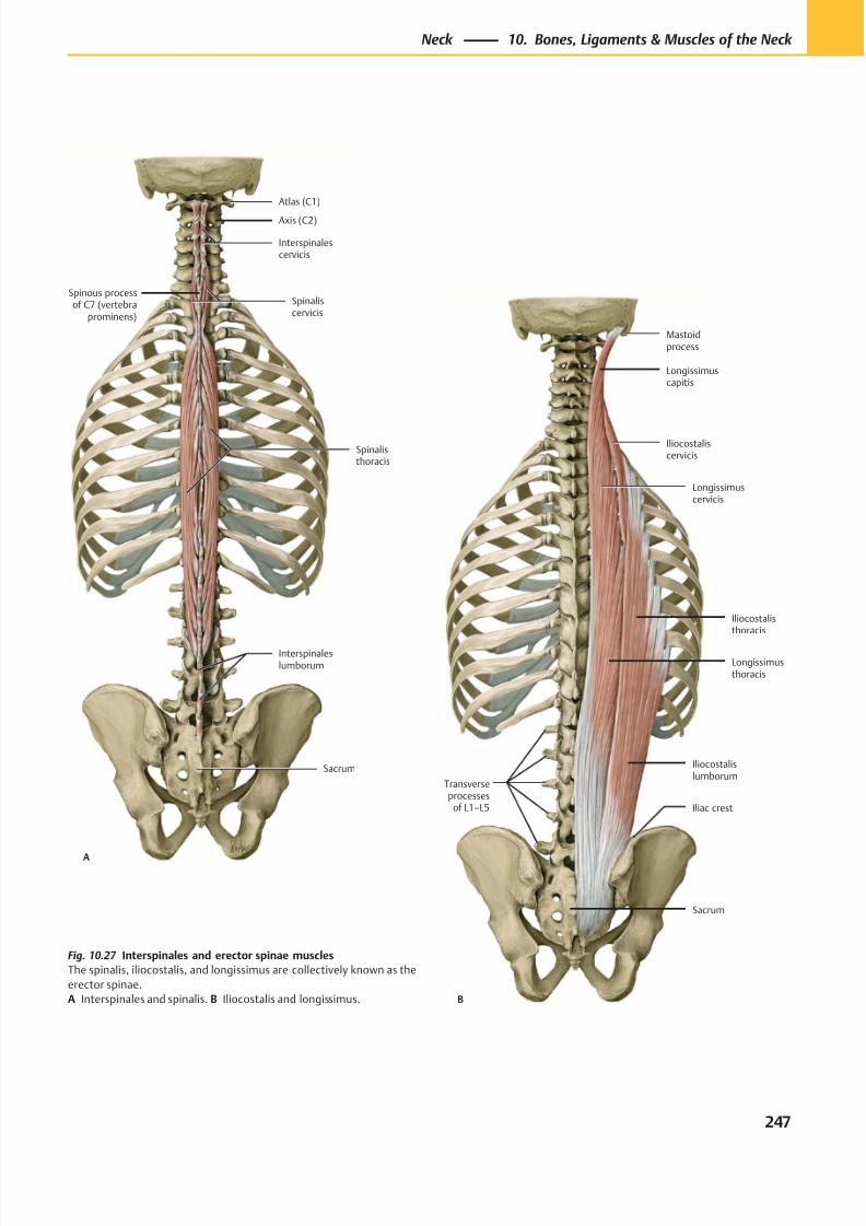
8/15/2019 Head and Neck Anatomy for Dental Medicine - Thieme; (January 26, 2010)
http://slidepdf.com/reader/full/head-and-neck-anatomy-for-dental-medicine-thieme-january-26-2010 260/384
Axis (C2)
Atlas (C1)
Spinous processof C7 (vertebra
prominens)
Interspinaleslumborum
Spinalisthoracis
Spinaliscervicis
Interspinalescervicis
Sacrum
A
Transverseprocesses
of L1–L5
Sacrum
Iliac crest
Iliocostalislumborum
Longissimusthoracis
Iliocostalisthoracis
Longissimuscervicis
Iliocostaliscervicis
Longissimuscapitis
Mastoidprocess
B
Fig. 10.27 Interspinales and erector spinae muscles
The spinalis, iliocostalis, and longissimus are collectively known as the
erector spinae.
A Interspinales and spinalis. B Iliocostalis and longissimus.
247
Neck 10. Bones, Ligaments & Muscles of the Neck
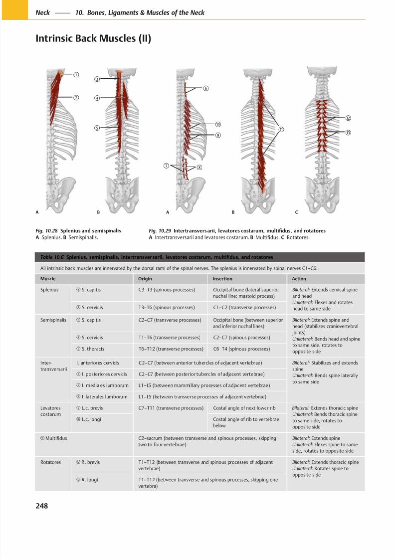
8/15/2019 Head and Neck Anatomy for Dental Medicine - Thieme; (January 26, 2010)
http://slidepdf.com/reader/full/head-and-neck-anatomy-for-dental-medicine-thieme-january-26-2010 261/384
A B
A B
C
Table 10.6
All intrinsic back muscles are innervated by the dorsal rami of the spinal nerves. The splenius is innervated by spinal nerves C1–C6.
Muscle Origin Insertion Action
Splenius S. capitis C3–T3 (spinous processes) Occipital bone (lateral superior
nuchal line; mastoid process)
Bilateral: Extends cervical spine
and head
Unilateral: Flexes and rotates
head to same side S. cervicis T3–T6 (spinous processes) C1–C2 (transverse processes)
Semispinalis S. capitis C2–C7 (transverse processes) Occipital bone (between superior
and inferior nuchal lines)
Bilateral: Extends spine and
head (stabilizes craniovertebral
joints)
Unilateral: Bends head and spine
to same side, rotates to
opposite side
S. cervicis T1–T6 (transverse processes) C2–C7 (spinous processes)
S. thoracis T6–T12 (transverse processes) C6–T4 (spinous processes)
Inter-
transversarii
I. anteriores cervicis C2–C7 (between anterior tubercles of adjacent vertebrae) Bilateral: Stabilizes and extends
spine
Unilateral: Bends spine laterally
to same side
I. posteriores cervicis C2–C7 (between posterior tubercles of adjacent vertebrae)
I. mediales lumborum L1–L5 (between mammillary processes of adjacent vertebrae)
I. laterales lumborum L1–L5 (between transverse processes of adjacent vertebrae)
Levatores
costarum
L.c. brevis C7–T11 (transverse processes) Costal angle of next lower rib Bilateral: Extends thoracic spine
Unilateral: Bends thoracic spine
to same side, rotates to
opposite side
L.c. longi Costal angle of rib to vertebrae
below
C2–sacrum (between transverse and spinous processes, skipping
two to four vertebrae)
Bilateral: Extends spine
Unilateral: Flexes spine to same
side, rotates to opposite side
Rotatores R . brevis T1–T12 (between transverse and spinous processes of adjacent
vertebrae)
Bilateral: Extends thoracic spine
Unilateral: Rotates spine to
opposite side R. longi T1–T12 (between transverse and spinous processes, skipping one
vertebra)
Fig. 10.28
A Splenius. B Semispinalis.
Fig. 10.29
A Intertransversarii and levatores costarum. B C Rotatores.
248
Neck 10. Bones, Ligaments & Muscles of the Neck
Intrinsic Back Muscles (II)
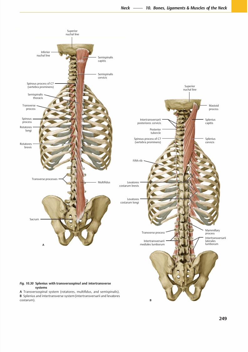
8/15/2019 Head and Neck Anatomy for Dental Medicine - Thieme; (January 26, 2010)
http://slidepdf.com/reader/full/head-and-neck-anatomy-for-dental-medicine-thieme-january-26-2010 262/384
Transverse processes
Sacrum
Superiornuchal line
Inferiornuchal line
Spinous process of C7(vertebra prominens)
Rotatoresbrevis
Spinous
processRotatores
longi
Transverseprocess
Semispinalisthoracis
Multifidus
Semispinalis
capitis
Semispinaliscervicis
A
Superiornuchal line
Intertransversarii
posteriores cervicis
Posteriortubercle
Spinous process of C7(vertebra prominens)
Intertransversariilateraleslumborum
Intertransversariimediales lumborum
Levatorescostarum longi
Levatores
costarum brevis
Fifth rib
Spleniuscervicis
Splenius
capitis
Mastoidprocess
Transverse processMammillaryprocess
B
Fig. 10.30 Splenius with transversospinal and intertransverse
systems
A
B
249
Neck 10. Bones, Ligaments & Muscles of the Neck
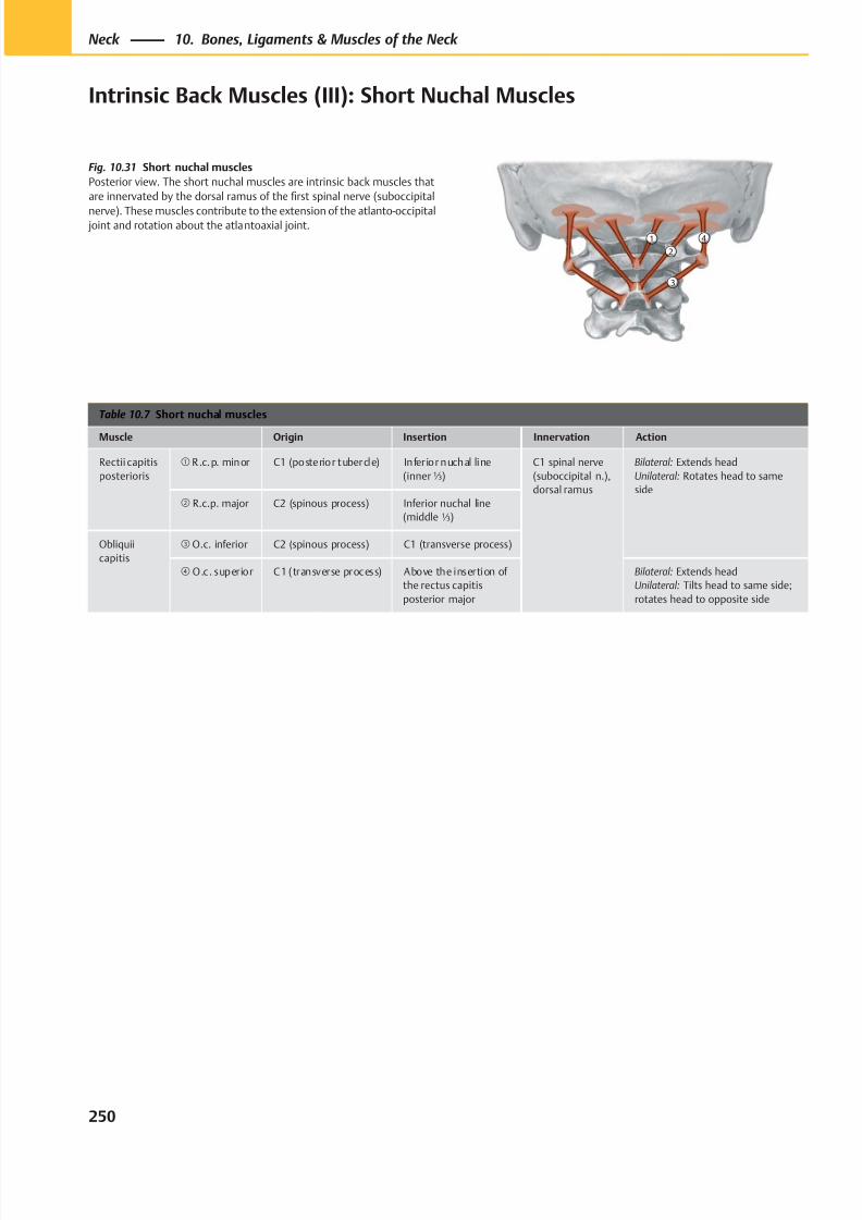
8/15/2019 Head and Neck Anatomy for Dental Medicine - Thieme; (January 26, 2010)
http://slidepdf.com/reader/full/head-and-neck-anatomy-for-dental-medicine-thieme-january-26-2010 263/384
②① ④
③
Table 10.7 Short nuchal muscles
Muscle Origin Insertion Innervation Action
Rectii capitis
posterioris
① R .c.p. minor C1 (posterior tubercle) Infer ior nuchal line
(inner⅓)
C1 spinal nerve
(suboccipital n.),
dorsal ramus
Bilateral: Extends head
Unilateral: Rotates head to same
side② R.c.p. major C2 (spinous process) Inferior nuchal line
(middle ⅓)
Obliquii
capitis
③ O.c. inferior C2 (spinous process) C1 (transverse process)
④ O.c. superior C1 (transverse process) Above the insertion of
the rectus capitis
posterior major
Bilateral: Extends head
Unilateral: Tilts head to same side;
rotates head to opposite side
Fig. 10.31 Short nuchal muscles
Posterior view. The short nuchal muscles are intrinsic back muscles that
are innervated by the dorsal ramus of the first spinal nerve (suboccipital
nerve). These muscles contribute to the extension of the atlanto-occipital joint and rotation about the atlantoaxial joint.
250
Neck 10. Bones, Ligaments & Muscles of the Neck
Intrinsic Back Muscles (III): Short Nuchal Muscles
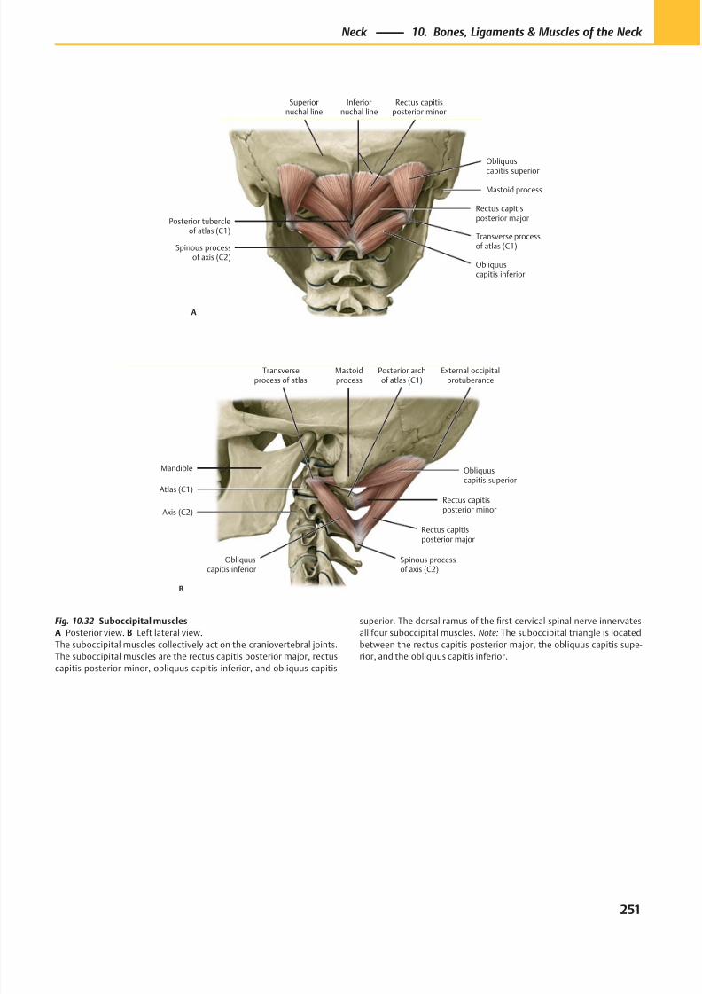
8/15/2019 Head and Neck Anatomy for Dental Medicine - Thieme; (January 26, 2010)
http://slidepdf.com/reader/full/head-and-neck-anatomy-for-dental-medicine-thieme-january-26-2010 264/384
Posterior tubercleof atlas (C1)
Superiornuchal line
Inferiornuchal line
Obliquus
capitis superior
Transverse processof atlas (C1)
Obliquuscapitis inferior
Spinous processof axis (C2)
Rectus capitisposterior major
Rectus capitisposterior minor
A
Mastoid process
Transverseprocess of atlas
Spinous processof axis (C2)
Obliquuscapitis inferior
Rectus capitisposterior major
Rectus capitisposterior minor
Obliquuscapitis superior
External occipitalprotuberance
Mastoidprocess
B
Mandible
Atlas (C1)
Axis (C2)
Posterior archof atlas (C1)
Fig. 10.32 Suboccipital muscles
A Posterior view. B Left lateral view.
The suboccipital muscles collectively act on the craniovertebral joints.
The suboccipital muscles are the rectus capitis posterior major, rectus
capitis posterior minor, obliquus capitis inferior, and obliquus capitis
superior. The dorsal ramus of the first cervical spinal nerve innervates
all four suboccipital muscles. Note: The suboccipital triangle is located
between the rectus capitis posterior major, the obliquus capitis supe-
rior, and the obliquus capitis inferior.
251
Neck 10. Bones, Ligaments & Muscles of the Neck
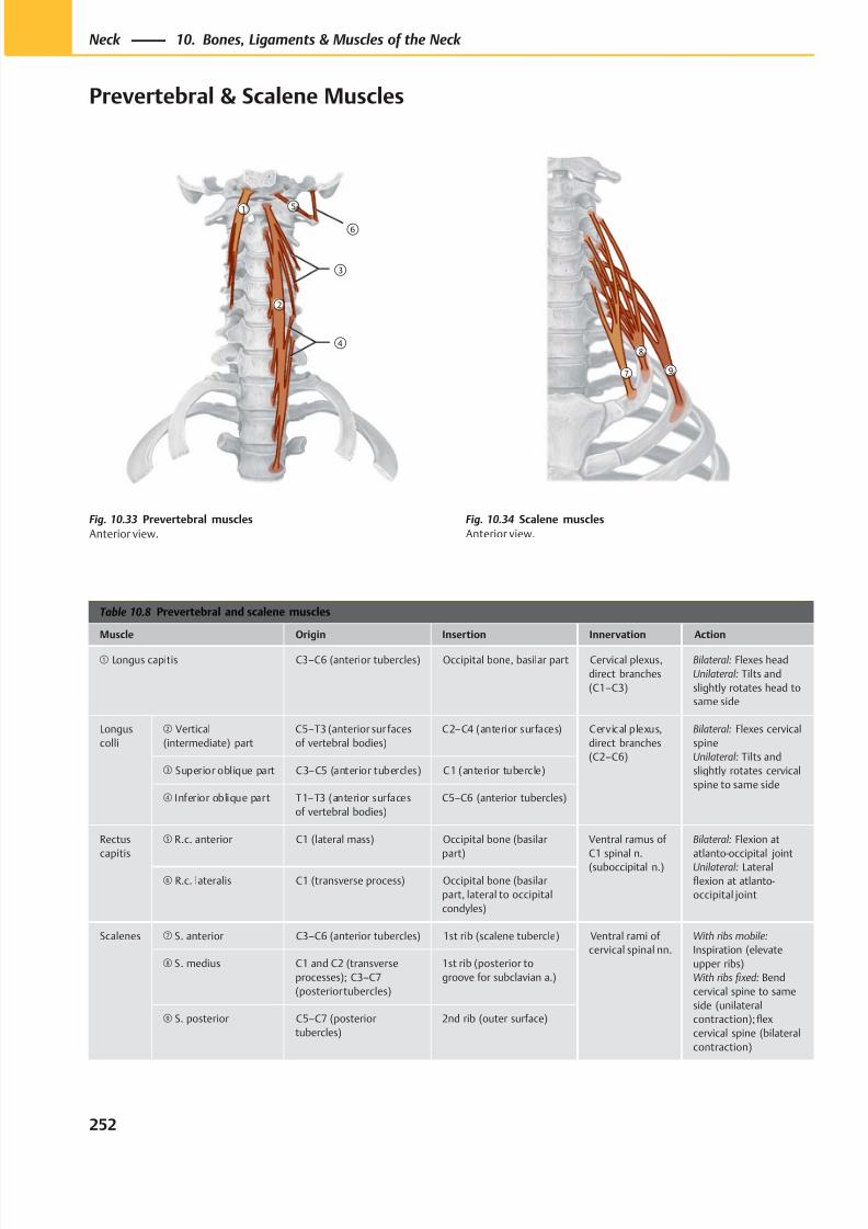
8/15/2019 Head and Neck Anatomy for Dental Medicine - Thieme; (January 26, 2010)
http://slidepdf.com/reader/full/head-and-neck-anatomy-for-dental-medicine-thieme-january-26-2010 265/384
①
②
⑤
⑥
③
④
⑦
⑧
⑨
Table 10.8 Prevertebral and scalene muscles
Muscle Origin Insertion Innervation Action
① Longus capitis C3–C6 (anterior tubercles) Occipital bone, basilar part Cervical plexus,
direct branches
(C1–C3)
Bilateral: Flexes head
Unilateral: Tilts and
slightly rotates head to
same side
Longus
colli
② Vertical
(intermediate) part
C5–T3 (anterior sur faces
of vertebral bodies)
C2–C4 (anterior surfaces) Cervical plexus,
direct branches
(C2–C6)
Bilateral: Flexes cervical
spine
Unilateral: Tilts and
slightly rotates cervical
spine to same side
③ Superior oblique part C3–C5 (anterior tubercles) C1 (anterior tubercle)
④ Inferior oblique part T1–T3 (anterior surfaces
of vertebral bodies)
C5–C6 (anterior tubercles)
Rectus
capitis
⑤ R.c. anterior C1 (lateral mass) Occipital bone (basilar
part)
Ventral ramus of
C1 spinal n.
(suboccipital n.)
Bilateral: Flexion at
atlanto-occipital joint
Unilateral: Lateral
flexion at atlanto-
occipital joint
⑥ R.c. lateralis C1 (transverse process) Occipital bone (basilar
part, lateral to occipital
condyles)
Scalenes ⑦ S. anterior C3–C6 (anterior tubercles) 1st rib (scalene tubercle) Ventral rami of
cervical spinal nn.
With ribs mobile:
Inspiration (elevate
upper ribs)
With ribs fi xed: Bend
cervical spine to same
side (unilateral
contraction); flex
cervical spine (bilateral
contraction)
⑧ S. medius C1 and C2 (transverse
processes); C3–C7
(posterior tubercles)
1st rib (posterior to
groove for subclavian a.)
⑨ S. posterior C5–C7 (posterior
tubercles)
2nd rib (outer surface)
Fig. 10.33 Prevertebral muscles
Anterior view.
Fig. 10.34 Scalene muscles
Anterior view.
252
Neck 10. Bones, Ligaments & Muscles of the Neck
Prevertebral & Scalene Muscles
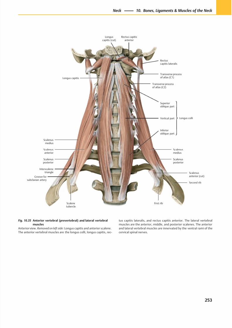
8/15/2019 Head and Neck Anatomy for Dental Medicine - Thieme; (January 26, 2010)
http://slidepdf.com/reader/full/head-and-neck-anatomy-for-dental-medicine-thieme-january-26-2010 266/384
Scalenusposterior
Scalenusmedius
Interscalene
triangle
Scalenusanterior
Inferioroblique part
Vertical part
Superioroblique part
Longus capitis
Rectuscapitis lateralis
Rectus capitisanterior
First rib
Second rib
Longus colli
Transverse processof atlas (C1)
Scalenusanterior (cut)
Scalenusmedius
Scalenusposterior
Groove forsubclavian artery
Scalenetubercle
Transverse processof atlas (C2)
Longuscapitis (cut)
Fig. 10.35 Anterior vertebral (prevertebral) and lateral vertebral
muscles
Anterior view. Removed on left side: Longus capitis and anterior scalene.The anterior vertebral muscles are the longus colli, longus capitis, rec-
tus capitis lateralis, and rectus capitis anterior. The lateral vertebral
muscles are the anterior, middle, and posterior scalenes. The anterior
and lateral vertebral muscles are innervated by the ventral rami of thecervical spinal nerves.
253
Neck 10. Bones, Ligaments & Muscles of the Neck
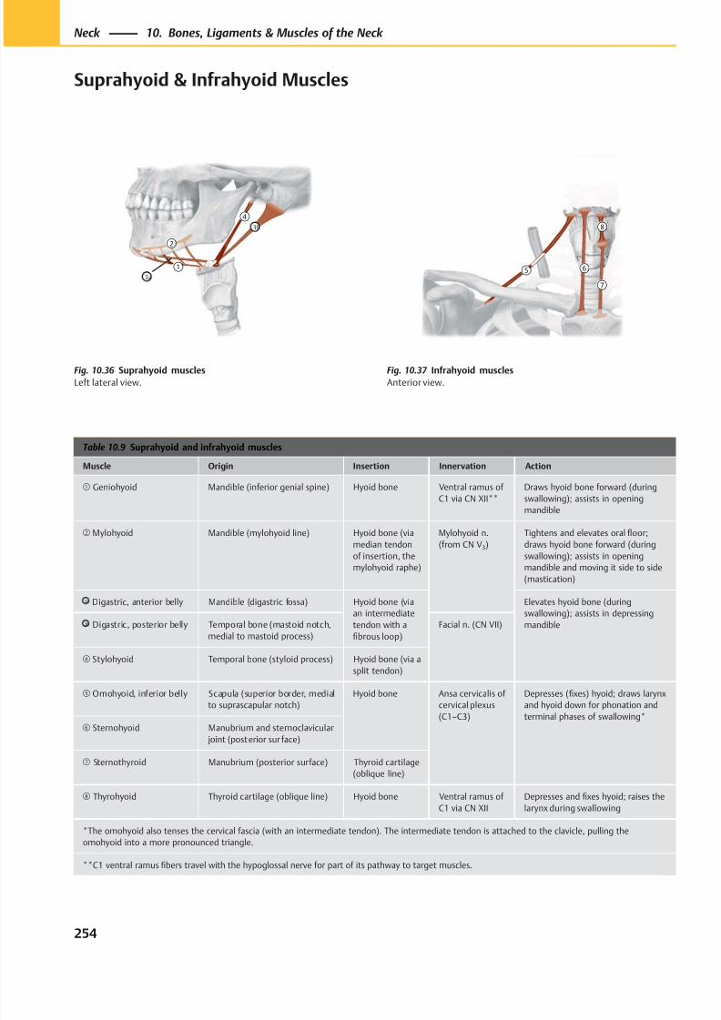
8/15/2019 Head and Neck Anatomy for Dental Medicine - Thieme; (January 26, 2010)
http://slidepdf.com/reader/full/head-and-neck-anatomy-for-dental-medicine-thieme-january-26-2010 267/384
⑤ ⑥
⑦
⑧
①
②
④3b
3a
Table 10.9 Suprahyoid and infrahyoid muscles
Muscle Origin Insertion Innervation Action
① Geniohyoid Mandible (inferior genial spine) Hyoid bone Ventral ramus of
C1 via CN XII**
Draws hyoid bone forward (during
swallowing); assists in opening
mandible
② Mylohyoid Mandible (mylohyoid line) Hyoid bone (viamedian tendon
of insertion, the
mylohyoid raphe)
Mylohyoid n.(from CN V3)
Tightens and elevates oral floor;draws hyoid bone forward (during
swallowing); assists in opening
mandible and moving it side to side
(mastication)
3a Digastric, anterior belly Mandible (digastric fossa) Hyoid bone (via
an intermediate
tendon with a
fibrous loop)
Elevates hyoid bone (during
swallowing); assists in depressing
mandible3b Digastric, posterior belly Temporal bone (mastoid notch,
medial to mastoid process)
Facial n. (CN VII)
④ Stylohyoid Temporal bone (styloid process) Hyoid bone (via a
split tendon)
⑤ Omohyoid, inferior belly Scapula (superior border, medial
to suprascapular notch)
Hyoid bone Ansa cervicalis of
cervical plexus
(C1–C3)
Depresses (fixes) hyoid; draws larynx
and hyoid down for phonation and
terminal phases of swallowing*⑥ Sternohyoid Manubrium and sternoclavicular
joint (posterior sur face)
⑦ Sternothyroid Manubrium (posterior surface) Thyroid cartilage
(oblique line)
⑧ Thyrohyoid Thyroid cartilage (oblique line) Hyoid bone Ventral ramus of
C1 via CN XII
Depresses and fixes hyoid; raises the
larynx during swallowing
*The omohyoid also tenses the cervical fascia (with an intermediate tendon). The intermediate tendon is attached to the clavicle, pulling the
omohyoid into a more pronounced triangle.
**C1 ventral ramus fibers travel with the hypoglossal nerve for part of its pathway to target muscles.
Fig. 10.36 Suprahyoid muscles
Left lateral view.
Fig. 10.37 Infrahyoid muscles
Anterior view.
254
Neck 10. Bones, Ligaments & Muscles of the Neck
Suprahyoid & Infrahyoid Muscles
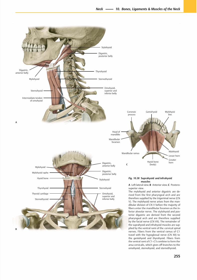
8/15/2019 Head and Neck Anatomy for Dental Medicine - Thieme; (January 26, 2010)
http://slidepdf.com/reader/full/head-and-neck-anatomy-for-dental-medicine-thieme-january-26-2010 268/384
Mylohyoid
Omohyoid,
superior andinferior belly
Sternohyoid
Hyoid boneStylohyoid
Digastric,posterior belly
Digastric,anterior belly
Sternothyroid
Mylohyoid raphe
Thyrohyoid
Thyroid cartilage
B
Digastric,anterior belly
Mylohyoid
Intermediate tendonof omohyoid
Omohyoid,superior andinferior belly
Sternothyroid
Thyrohyoid
Digastric,posterior belly
Stylohyoid
Sternohyoid
A
Hyoid bone(body)
Mandibularforamen
Mandibular ramus
Coronoidprocess
Head of mandible
Geniohyoid Mylohyoidline
Mylohyoid
Lesser horn
Greaterhorn
C
Fig. 10.38 Suprahyoid and infrahyoid
muscles
A Left lateral view. B Anterior view. C Postero-
superior view.
The mylohyoid and anterior digastric are de-
rived from thefi
rst pharyngeal arch and aretherefore supplied by the trigeminal nerve (CN
V). The mylohyoid nerve arises from the man-
dibular division of CN V before the majority of
fibers enter the mandibular foramen as the in-
ferior alveolar nerve. The stylohyoid and pos-
terior digastric are derived from the second
pharyngeal arch and are therefore supplied
by the facial nerve (CN VII). The remainder of
the suprahyoid and infrahyoid muscles are sup-
plied by the ventral rami of the cervical spinal
nerves. Fibers from the ventral ramus of C1
travel with the hypoglossal nerve (CN XII) to
the geniohyoid and thyrohyoid. Fibers from
the ventral rami of C1–C3 combine to form the
ansa cervicalis, which gives off branches to theomohyoid, sternohyoid, and sternothyroid.
255
Neck 10. Bones, Ligaments & Muscles of the Neck
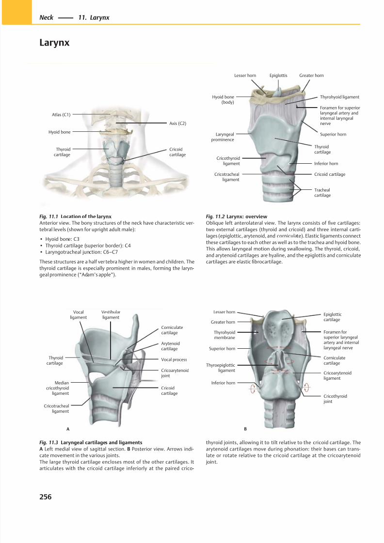
8/15/2019 Head and Neck Anatomy for Dental Medicine - Thieme; (January 26, 2010)
http://slidepdf.com/reader/full/head-and-neck-anatomy-for-dental-medicine-thieme-january-26-2010 269/384
Cricoidcartilage
Hyoid bone
Thyroidcartilage
Axis (C2)
Atlas (C1)
Laryngealprominence
Cricotrachealligament
Inferior horn
Superior horn
Thyrohyoid ligament
Greater hornEpiglottisLesser horn
Hyoid bone(body)
Foramen for superiorlaryngeal artery andinternal laryngealnerve
Cricothyroidligament
Thyroidcartilage
Cricoid cartilage
Trachealcartilage
A
Thyroidcartilage
Vocalligament
Mediancricothyroid
ligament
Cricotrachealligament
Vocal process
Cricoidcartilage
Cricoarytenoid joint
Corniculatecartilage
Vestibularligament
Arytenoidcartilage
CorniculatecartilageThyroepiglottic
ligament
Inferior horn
Cricoarytenoid
ligament
Superior horn
Thyrohyoidmembrane
Foramen forsuperior laryngealartery and internallaryngeal nerve
Greater horn
Lesser hornEpiglotticcartilage
B
Cricothyroid joint
Fig. 11.1 Location of the larynx
Anterior view. The bony structures of the neck have characteristic ver-
tebral levels (shown for upright adult male):
• Hyoid bone: C3
• Thyroid cartilage (superior border): C4
• Laryngotracheal junction: C6–C7
These structures are a half ver tebra higher in women and children. The
thyroid cartilage is especially prominent in males, forming the laryn-
geal prominence (“Adam’s apple”).
Fig. 11.3 Laryngeal cartilages and ligaments
A Left medial view of sagittal section. B Posterior view. Arrows indi-
cate movement in the various joints.
The large thyroid cartilage encloses most of the other cartilages. It
articulates with the cricoid cartilage inferiorly at the paired crico-
Fig. 11.2 Larynx: overview
Oblique left anterolateral view. The larynx consists of five cartilages:
two external cartilages (thyroid and cricoid) and three internal carti-
lages (epiglottic, arytenoid, and corniculate). Elastic ligaments connect
these cartilages to each other as well as to the trachea and hyoid bone.
This allows laryngeal motion during swallowing. The thyroid, cricoid,
and arytenoid cartilages are hyaline, and the epiglottis and corniculate
cartilages are elastic fibrocartilage.
thyroid joints, allowing it to tilt relative to the cricoid cartilage. The
arytenoid cartilages move during phonation: their bases can trans-
late or rotate relative to the cricoid cartilage at the cricoarytenoid
joint.
256
Neck 11. Larynx
Larynx
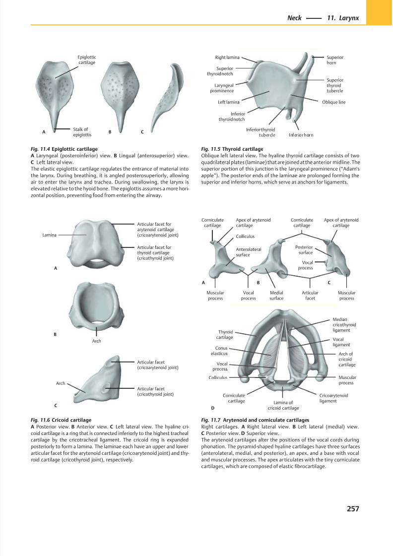
8/15/2019 Head and Neck Anatomy for Dental Medicine - Thieme; (January 26, 2010)
http://slidepdf.com/reader/full/head-and-neck-anatomy-for-dental-medicine-thieme-january-26-2010 270/384
Epiglotticcartilage
Stalk ofepiglottis
A B C
Arch
Arch
Articular facet(cricothyroid joint)
Articular facet(cricoarytenoid joint)
Lamina
Articular facet forthyroid cartilage(cricothyroid joint)
Articular facet forarytenoid cartilage(cricoarytenoid joint)
C
A
B
Posteriorsurface
Medialsurface
Articularfacet
Colliculus
Corniculatecartilage
Apex of arytenoidcartilage
Vocalprocess
Muscularprocess
Muscularprocess
Apex of arytenoidcartilage
Corniculatecartilage
Vocalprocess
A B C
Anterolateralsurface
Thyroidcartilage
Vocalprocess
Corniculatecartilage Lamina of
cricoid cartilage
Cricoarytenoidligament
Muscularprocess
Arch ofcricoidcartilage
Vocalligament
Colliculus
D
Conuselasticus
Mediancricothyroidligament
Fig. 11.4 Epiglottic cartilage
A Laryngeal (posteroinferior) view. B Lingual (anterosuperior) view.
C Left lateral view.
The elastic epiglottic cartilage regulates the entrance of material into
the larynx. During breathing, it is angled posterosuperiorly, allowing
air to enter the larynx and trachea. During swallowing, the larynx is
elevated relative to the hyoid bone. The epiglottis assumes a more hori-
zontal position, preventing food from entering the airway.
Fig. 11.7 Arytenoid and corniculate cartilages
Right cartilages. A Right lateral view. B Left lateral (medial) view.
C Posterior view. D Superior view.
The arytenoid cartilages alter the positions of the vocal cords during
phonation. The pyramid-shaped hyaline cartilages have three sur faces
(anterolateral, medial, and posterior), an apex, and a base with vocal
and muscular processes. The apex articulates with the tiny corniculate
cartilages, which are composed of elastic fibrocartilage.
Fig. 11.6 Cricoid cartilage
A Posterior view. B Anterior view. C Left lateral view. The hyaline cri-
coid cartilage is a ring that is connected inferiorly to the highest tracheal
cartilage by the cricotracheal ligament. The cricoid ring is expanded
posteriorly to form a lamina. The laminae each have an upper and lower
articular facet for the arytenoid cartilage (cricoarytenoid joint) and thy-
roid cartilage (cricothyroid joint), respectively.
Fig. 11.5 Thyroid cartilage
Oblique left lateral view. The hyaline thyroid cartilage consists of two
quadrilateral plates (laminae) that are joined at the anterior midline. The
superior portion of this junction is the laryngeal prominence (“Adam’s
apple”). The posterior ends of the laminae are prolonged forming the
superior and inferior horns, which serve as anchors for ligaments.
257
Neck 11. Larynx
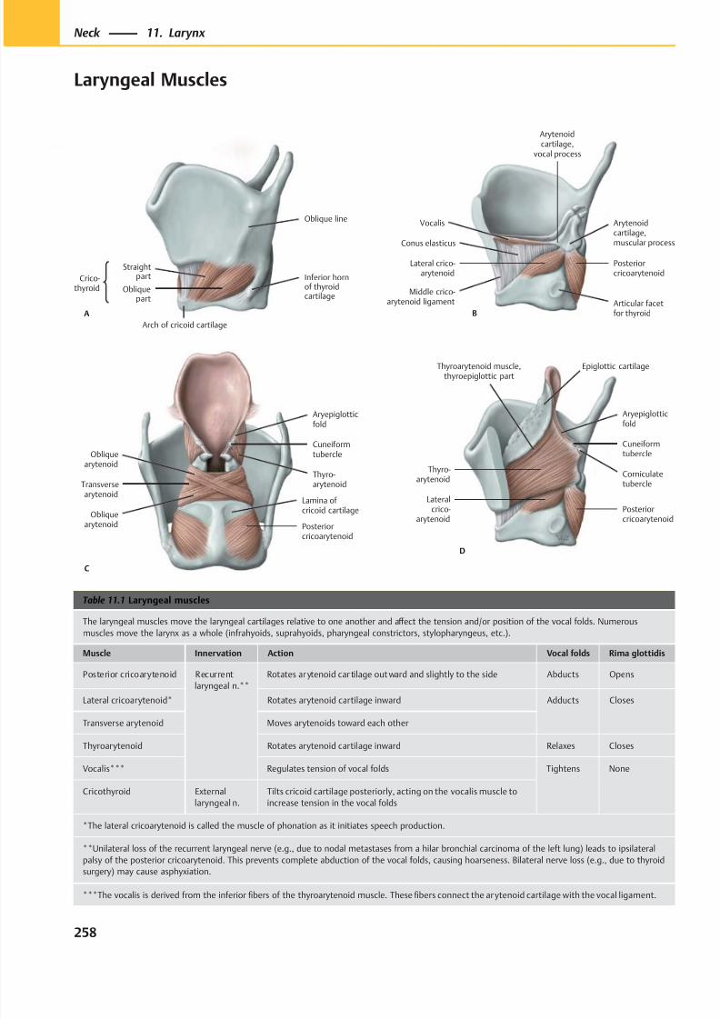
8/15/2019 Head and Neck Anatomy for Dental Medicine - Thieme; (January 26, 2010)
http://slidepdf.com/reader/full/head-and-neck-anatomy-for-dental-medicine-thieme-january-26-2010 271/384
A
Crico-thyroid
Straightpart
Obliquepart
Oblique line
Inferior hornof thyroidcartilage
Arch of cricoid cartilage
B
Lateral crico-arytenoid
Articular facetfor thyroid
Posteriorcricoarytenoid
Arytenoidcartilage,muscular process
Vocalis
Arytenoidcartilage,
vocal process
Conus elasticus
Middle crico-arytenoid ligament
Posterior
cricoarytenoid
Transversearytenoid
Obliquearytenoid
Thyro-arytenoid
Cuneiformtubercle
Aryepiglotticfold
Obliquearytenoid
C
Lamina of cricoid cartilage
D
Lateralcrico-
arytenoidPosteriorcricoarytenoid
Thyro-arytenoid
Corniculatetubercle
Cuneiformtubercle
Aryepiglotticfold
Thyroarytenoid muscle,thyroepiglottic part
Epiglottic cartilage
Table 11.1 Laryngeal muscles
The laryngeal muscles move the laryngeal cartilages relative to one another and aff ect the tension and/or position of the vocal folds. Numerous
muscles move the larynx as a whole (infrahyoids, suprahyoids, pharyngeal constrictors, stylopharyngeus, etc.).
Muscle Innervation Action Vocal folds Rima glottidis
Posterior cricoarytenoid Recurrent
laryngeal n.**
Rotates ar ytenoid car tilage out ward and slightly to the side Abducts Opens
Lateral cricoarytenoid* Rotates arytenoid cartilage inward Adducts Closes
Transverse arytenoid Moves arytenoids toward each other
Thyroarytenoid Rotates arytenoid cartilage inward Relaxes Closes
Vocalis*** Regulates tension of vocal folds Tightens None
Cricothyroid External
laryngeal n.
Tilts cricoid cartilage posteriorly, acting on the vocalis muscle to
increase tension in the vocal folds
*The lateral cricoarytenoid is called the muscle of phonation as it initiates speech production.
**Unilateral loss of the recurrent laryngeal nerve (e.g., due to nodal metastases from a hilar bronchial carcinoma of the left lung) leads to ipsilateral
palsy of the posterior cricoarytenoid. This prevents complete abduction of the vocal folds, causing hoarseness. Bilateral nerve loss (e.g., due to thyroid
surgery) may cause asphyxiation.
***The vocalis is derived from the inferior fibers of the thyroarytenoid muscle. These fibers connect the arytenoid cartilage with the vocal ligament.
258
Neck 11. Larynx
Laryngeal Muscles
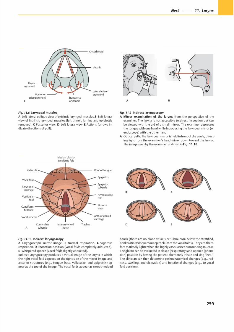
8/15/2019 Head and Neck Anatomy for Dental Medicine - Thieme; (January 26, 2010)
http://slidepdf.com/reader/full/head-and-neck-anatomy-for-dental-medicine-thieme-january-26-2010 272/384
Posteriorcricoarytenoid Transverse
arytenoid
Lateral crico-arytenoid
Thyro-arytenoid
Vocalis
Cricothyroid
E A B
B C
D E
Cuneiformtubercle
Vocal process
Corniculatetubercle
TracheaInterarytenoidnotch
Arch of cricoidcartilage
Piriformsinus
Aryepiglotticfold
Epiglottis
Vallecula Root of tongue
Median glosso-epiglottic fold
Epiglottictubercle
Vocal fold
Laryngealventricle
Vestibularfold
A
Fig. 11.8 Laryngeal muscles
A Left lateral oblique view of extrinsic laryngeal muscles. B Left lateralview of intrinsic laryngeal muscles (left thyroid lamina and epiglottis
removed). C Posterior view. D Left lateral view. E Actions (arrows in-
dicate directions of pull).
Fig. 11.9 Indirect laryngoscopy
A Mirror examination of the larynx from the perspective of theexaminer. The larynx is not accessible to direct inspection but can
be viewed with the aid of a small mirror. The examiner depresses
the tongue with one hand while introducing the laryngeal mirror (or
endoscope) with the other hand.
A Optical path: The laryngeal mirror is held in front of the uvula, direct-
ing light from the examiner’s head mirror down toward the larynx.
The image seen by the examiner is shown in Fig. 11.10.
Fig. 11.10 Indirect laryngoscopy
A Laryngoscopic mirror image. B Normal respiration. C Vigorous
respiration. D Phonation position (vocal folds completely adducted).
E Whispered speech (vocal folds slightly abducted).
Indirect laryngoscopy produces a virtual image of the larynx in which
the right vocal fold appears on the right side of the mirror image and
anterior structures (e.g., tongue base, valleculae, and epiglottis) ap-
pear at the top of the image. The vocal folds appear as smooth-edged
bands (there are no blood vessels or submucosa below the stratified,
nonkeratinized squamous epithelium of the vocal folds). They are there-
fore markedly lighter than the highly vascularized surrounding mucosa.
The glottis can be evaluated in closed (respiratory) and opened (phona-
tion) position by having the patient alternately inhale and sing “hee.”
The clinician can then determine pathoanatomical changes (e.g., red-
ness, swelling, and ulceration) and functional changes (e.g., to vocal
fold position).
259
Neck 11. Larynx
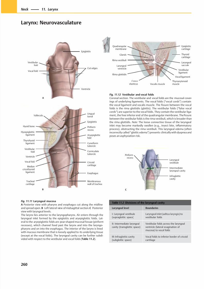
8/15/2019 Head and Neck Anatomy for Dental Medicine - Thieme; (January 26, 2010)
http://slidepdf.com/reader/full/head-and-neck-anatomy-for-dental-medicine-thieme-january-26-2010 273/384
A
Epiglottis
Vestibularfold
Vocal foldCut edges
Ventricle
Corniculatetubercle
Cuneiformtubercle
Aryepiglotticfold
Piriformrecess
Lingualtonsil
B
Hyoid bone
Hyoepiglotticligament
Thyrohyoidligament
Mediancricothyroid
ligament
Trachealcartilage
Vocal fold
Vestibular
fold
Epiglottis
Ventricle
Membranouswall of trachea
Esophagus
Cricoidcartilage
Vallecula
Rima vestibuli
Laryngealventricle
Rima glottidis
Glands
Quadrangularmembrane
Vocalis muscle
Thyroidcartilage
Laryngealsaccule
Epiglotticcartilage
Conuselasticus
Vocal ligament
Thyroarytenoidmuscle
Vestibularligament
Infraglotticcavity
Intermediatelaryngeal cavity
Laryngealvestibule
Piriformrecess
C
Table 11.2 Divisions of the laryngeal cavity
Laryngeal level Boundaries
I: Laryngeal vestibule
(supraglottic space)
Laryngeal inlet (aditus laryngis) to
vestibular folds
II: Intermediate laryngeal
cavity (transglottic space)
Vestibular folds across the laryngeal
ventricle (lateral evagination of
mucosa) to vocal folds
III: Infraglottic cavity
(subglottic space)
Vocal folds to inferior border of cricoid
cartilage
Fig. 11.11 Laryngeal mucosaA Posterior view with pharynx and esophagus cut along the midline
and spread open. B Left lateral view of midsagittal section. C Posterior
view with laryngeal levels.
The larynx lies anterior to the laryngopharynx. Air enters through the
laryngeal inlet formed by the epiglottis and aryepiglottic folds. Lat-
eral to the aryepiglottic folds are pear-shaped mucosal fossae (piriform
recesses), which channel food past the larynx and into the laryngo-
pharynx and on into the esophagus. The interior of the larynx is lined
with mucous membrane that is loosely applied to its underlying tissue
(except at the vocal folds). The laryngeal cavity can be further subdi-
vided with respect to the vestibular and vocal folds (Table 11.2).
Fig. 11.12 Vestibular and vocal folds
Coronal section. The vestibular and vocal folds are the mucosal cover-
ings of underlying ligaments. The vocal folds (“vocal cords”) containthe vocal ligament and vocalis muscle. The fissure between the vocal
folds is the rima glottidis (glottis). The vestibular folds (“false vocal
cords”) are superior to the vocal folds. They contain the vestibular liga-
ment, the free inferior end of the quadrangular membrane. The fissure
between the vestibular folds is the rima vestibuli, which is broader than
the rima glottidis. Note: The loose connective tissue of the laryngeal
inlet may become markedly swollen (e.g., insect bite, inflammatory
process), obstructing the rima vestibuli. This laryngeal edema (often
incorrectly called “glottic edema”) presents clinically with dyspnea and
poses an asphyxiation risk.
260
Neck 11. Larynx
Larynx: Neurovasculature
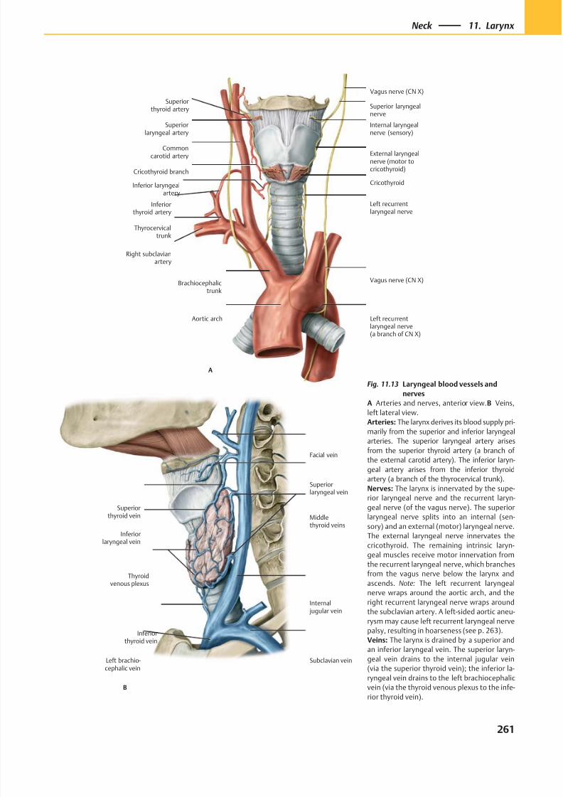
8/15/2019 Head and Neck Anatomy for Dental Medicine - Thieme; (January 26, 2010)
http://slidepdf.com/reader/full/head-and-neck-anatomy-for-dental-medicine-thieme-january-26-2010 274/384
B
Superiorlaryngeal vein
Superiorthyroid vein
Internal jugular vein
Middlethyroid veins
Facial vein
Inferiorlaryngeal vein
Thyroidvenous plexus
Inferiorthyroid vein
Left brachio-cephalic vein
Subclavian vein
Superiorlaryngeal artery
Commoncarotid artery
Cricothyroid branch
Inferior laryngealartery
Inferiorthyroid artery
Thyrocervicaltrunk
Right subclavianartery
Left recurrentlaryngeal nerve
Cricothyroid
External laryngealnerve (motor tocricothyroid)
Vagus nerve (CN X)
Brachiocephalictrunk
Aortic arch Left recurrentlaryngeal nerve(a branch of CN X)
Superiorthyroid artery
Internal laryngealnerve (sensory)
A
Superior laryngealnerve
Vagus nerve (CN X)
Fig. 11.13 Laryngeal blood vessels and
nerves
A Arteries and nerves, anterior view. B Veins,
left lateral view.
Arteries: The larynx derives its blood supply pri-
marily from the superior and inferior laryngeal
arteries. The superior laryngeal artery arises
from the superior thyroid artery (a branch of
the external carotid artery). The inferior laryn-
geal artery arises from the inferior thyroid
artery (a branch of the thyrocervical trunk).
Nerves: The larynx is innervated by the supe-
rior laryngeal nerve and the recurrent laryn-
geal nerve (of the vagus nerve). The superior
laryngeal nerve splits into an internal (sen-
sory) and an external (motor) laryngeal nerve.
The external laryngeal nerve innervates the
cricothyroid. The remaining intrinsic laryn-
geal muscles receive motor innervation fromthe recurrent laryngeal nerve, which branches
from the vagus nerve below the larynx and
ascends. Note: The left recurrent laryngeal
nerve wraps around the aortic arch, and the
right recurrent laryngeal nerve wraps around
the subclavian artery. A left-sided aortic aneu-
rysm may cause left recurrent laryngeal nerve
palsy, resulting in hoarseness (see p. 263).
Veins: The larynx is drained by a superior and
an inferior laryngeal vein. The superior laryn-
geal vein drains to the internal jugular vein
(via the superior thyroid vein); the inferior la-
ryngeal vein drains to the left brachiocephalic
vein (via the thyroid venous plexus to the infe-
rior thyroid vein).
261
Neck 11. Larynx
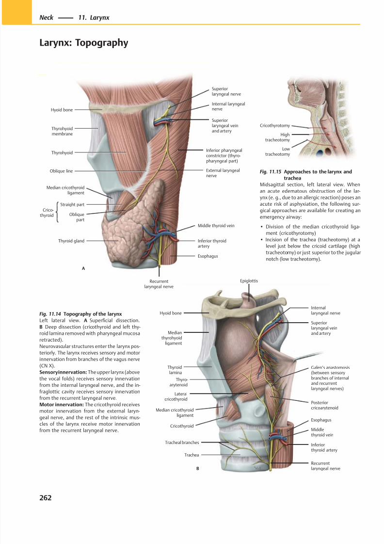
8/15/2019 Head and Neck Anatomy for Dental Medicine - Thieme; (January 26, 2010)
http://slidepdf.com/reader/full/head-and-neck-anatomy-for-dental-medicine-thieme-january-26-2010 275/384
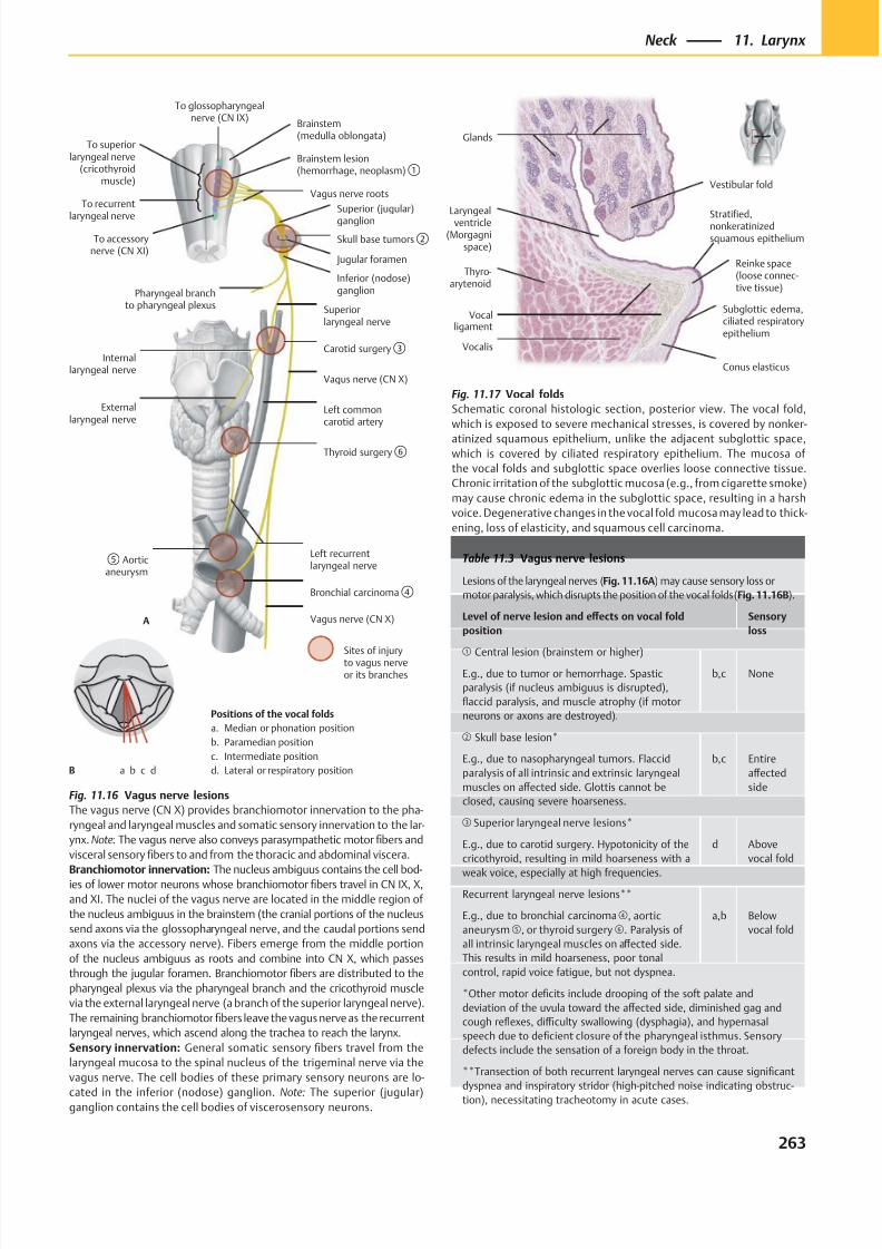
8/15/2019 Head and Neck Anatomy for Dental Medicine - Thieme; (January 26, 2010)
http://slidepdf.com/reader/full/head-and-neck-anatomy-for-dental-medicine-thieme-january-26-2010 276/384
Conus elasticus
Subglottic edema,ciliated respiratoryepithelium
Laryngealventricle
(Morgagnispace)
Thyro-arytenoid
Reinke space(loose connec-tive tissue)
Stratified,nonkeratinizedsquamous epithelium
Vocalis
Vestibular fold
Glands
Vocalligament
Brainstem(medulla oblongata)
Brainstem lesion(hemorrhage, neoplasm)①
Vagus nerve roots
Jugular foramen
Skull base tumors②
Superiorlaryngeal nerve
Carotid surgery③
Vagus nerve (CN X)
Left commoncarotid artery
Left recurrentlaryngeal nerve
⑤ Aorticaneurysm
Bronchial carcinoma④
Vagus nerve (CN X)
Internallaryngeal nerve
Inferior (nodose)ganglion
Superior (jugular)
ganglion
Thyroid surgery⑥
Sites of injuryto vagus nerveor its branches
A
Pharyngeal branchto pharyngeal plexus
To superiorlaryngeal nerve
(cricothyroidmuscle)
To recurrent
laryngeal nerve
To accessorynerve (CN XI)
To glossopharyngealnerve (CN IX)
Externallaryngeal nerve
Positions of the vocal folds
a. Median or phonation position
b. Paramedian position
c. Intermediate position
d. Lateral or respiratory positiona b c dB
Table 11.3 Vagus nerve lesions
Lesions of the laryngeal nerves (Fig. 11.16A) may cause sensory loss or
motor paralysis, which disrupts the position of the vocal folds (Fig. 11.16B).
Level of nerve lesion and eff ects on vocal fold
position
Sensory
loss
① Central lesion (brainstem or higher)
E.g., due to tumor or hemorrhage. Spastic
paralysis (if nucleus ambiguus is disrupted),
flaccid paralysis, and muscle atrophy (if motor
neurons or axons are destroyed).
b,c None
② Skull base lesion*
E.g., due to nasopharyngeal tumors. Flaccid
paralysis of all intrinsic and extrinsic laryngeal
muscles on aff ected side. Glottis cannot be
closed, causing severe hoarseness.
b,c Entire
aff ected
side
③ Superior laryngeal nerve lesions*
E.g., due to carotid surgery. Hypotonicity of the
cricothyroid, resulting in mild hoarseness with a
weak voice, especially at high frequencies.
d Above
vocal fold
Recurrent laryngeal nerve lesions**
E.g., due to bronchial carcinoma ④, aortic
aneurysm⑤, or thyroid surgery ⑥. Paralysis of
all intrinsic laryngeal muscles on aff ected side.
This results in mild hoarseness, poor tonal
control, rapid voice fatigue, but not dyspnea.
a,b Below
vocal fold
*Other motor deficits include drooping of the soft palate and
deviation of the uvula toward the aff ected side, diminished gag and
cough reflexes, diffi culty swallowing (dysphagia), and hypernasal
speech due to deficient closure of the pharyngeal isthmus. Sensory
defects include the sensation of a foreign body in the throat.
**Transection of both recurrent laryngeal nerves can cause significant
dyspnea and inspiratory stridor (high-pitched noise indicating obstruc-
tion), necessitating tracheotomy in acute cases.
Fig. 11.17 Vocal folds
Schematic coronal histologic section, posterior view. The vocal fold,
which is exposed to severe mechanical stresses, is covered by nonker-
atinized squamous epithelium, unlike the adjacent subglottic space,which is covered by ciliated respiratory epithelium. The mucosa of
the vocal folds and subglottic space overlies loose connective tissue.
Chronic irritation of the subglottic mucosa (e.g., from cigarette smoke)
may cause chronic edema in the subglottic space, resulting in a harsh
voice. Degenerative changes in the vocal fold mucosa may lead to thick-
ening, loss of elasticity, and squamous cell carcinoma.
Fig. 11.16 Vagus nerve lesions
The vagus nerve (CN X) provides branchiomotor innervation to the pha-
ryngeal and laryngeal muscles and somatic sensory innervation to the lar-
ynx. Note: The vagus nerve also conveys parasympathetic motor fibers and
visceral sensory fibers to and from the thoracic and abdominal viscera.
Branchiomotor innervation: The nucleus ambiguus contains the cell bod-ies of lower motor neurons whose branchiomotor fibers travel in CN IX, X,
and XI. The nuclei of the vagus nerve are located in the middle region of
the nucleus ambiguus in the brainstem (the cranial portions of the nucleus
send axons via the glossopharyngeal nerve, and the caudal portions send
axons via the accessory nerve). Fibers emerge from the middle portion
of the nucleus ambiguus as roots and combine into CN X, which passes
through the jugular foramen. Branchiomotor fibers are distributed to the
pharyngeal plexus via the pharyngeal branch and the cricothyroid muscle
via the external laryngeal nerve (a branch of the superior laryngeal nerve).
The remaining branchiomotor fibers leave the vagus nerve as the recurrent
laryngeal nerves, which ascend along the trachea to reach the larynx.
Sensory innervation: General somatic sensory fibers travel from the
laryngeal mucosa to the spinal nucleus of the trigeminal nerve via the
vagus nerve. The cell bodies of these primary sensory neurons are lo-
cated in the inferior (nodose) ganglion. Note: The superior (jugular)ganglion contains the cell bodies of viscerosensory neurons.
263
Neck 11. Larynx
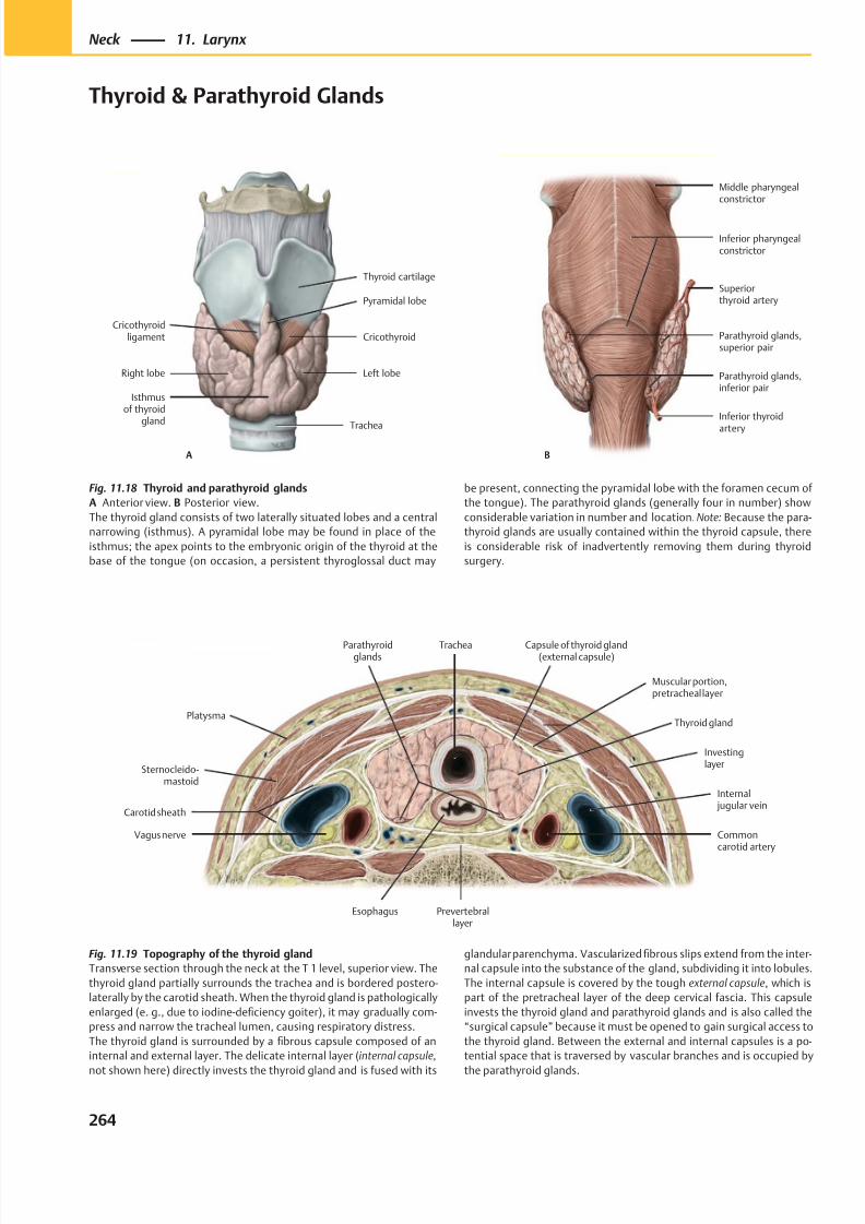
8/15/2019 Head and Neck Anatomy for Dental Medicine - Thieme; (January 26, 2010)
http://slidepdf.com/reader/full/head-and-neck-anatomy-for-dental-medicine-thieme-january-26-2010 277/384
Trachea
Left lobe
Isthmusof thyroid
gland
Right lobe
Pyramidal lobe
CricothyroidCricothyroid
ligament
Thyroid cartilage
A
Inferior thyroid
artery
Parathyroid glands,inferior pair
Parathyroid glands,superior pair
Superiorthyroid artery
B
Middle pharyngealconstrictor
Inferior pharyngealconstrictor
Fig. 11.18 Thyroid and parathyroid glands
A Anterior view. B Posterior view.
The thyroid gland consists of two laterally situated lobes and a central
narrowing (isthmus). A pyramidal lobe may be found in place of the
isthmus; the apex points to the embryonic origin of the thyroid at the
base of the tongue (on occasion, a persistent thyroglossal duct may
Fig. 11.19 Topography of the thyroid gland
Transverse section through the neck at the T 1 level, superior view. The
thyroid gland partially surrounds the trachea and is bordered postero-
laterally by the carotid sheath. When the thyroid gland is pathologically
enlarged (e. g., due to iodine-deficiency goiter), it may gradually com-
press and narrow the tracheal lumen, causing respiratory distress.
The thyroid gland is surrounded by a fibrous capsule composed of an
internal and external layer. The delicate internal layer ( internal capsule,
not shown here) directly invests the thyroid gland and is fused with its
glandular parenchyma. Vascularized fibrous slips extend from the inter-
nal capsule into the substance of the gland, subdividing it into lobules.
The internal capsule is covered by the tough external capsule, which is
part of the pretracheal layer of the deep cervical fascia. This capsule
invests the thyroid gland and parathyroid glands and is also called the
“surgical capsule” because it must be opened to gain surgical access to
the thyroid gland. Between the external and internal capsules is a po-
tential space that is traversed by vascular branches and is occupied by
the parathyroid glands.
be present, connecting the pyramidal lobe with the foramen cecum of
the tongue). The parathyroid glands (generally four in number) show
considerable variation in number and location. Note: Because the para-
thyroid glands are usually contained within the thyroid capsule, there
is considerable risk of inadvertently removing them during thyroid
surgery.
264
Neck 11. Larynx
Thyroid & Parathyroid Glands
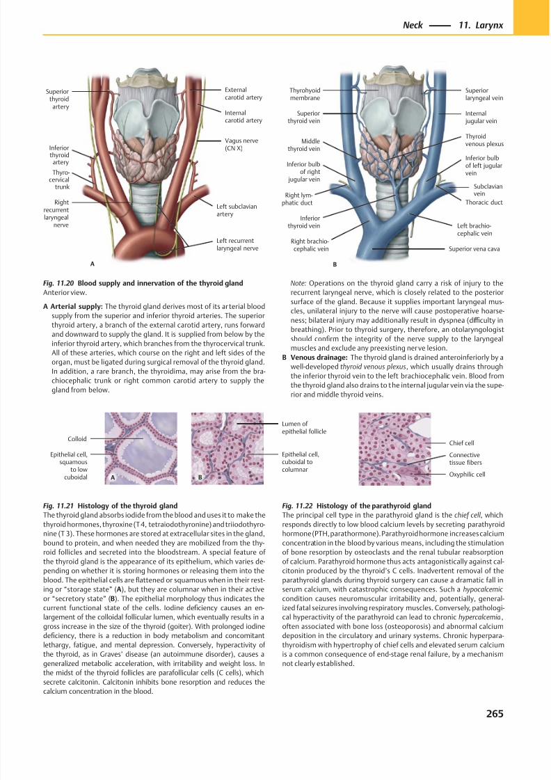
8/15/2019 Head and Neck Anatomy for Dental Medicine - Thieme; (January 26, 2010)
http://slidepdf.com/reader/full/head-and-neck-anatomy-for-dental-medicine-thieme-january-26-2010 278/384
B
Superior vena cava
Left brachio-cephalic vein
Subclavianvein
Thoracic duct
Inferior bulbof left jugularvein
Internal jugular vein
Superiorthyroid vein
Superiorlaryngeal vein
Thyrohyoidmembrane
Middlethyroid vein
Inferior bulbof right
jugular vein
Right lym-phatic duct
Right brachio-cephalic vein
Inferiorthyroid vein
Thyroidvenous plexus
A
Thyro-cervical
trunk
Rightrecurrentlaryngeal
nerve
Vagus nerve(CN X)
Superiorthyroid
artery
Externalcarotid artery
Internalcarotid artery
Inferiorthyroidartery
Left recurrentlaryngeal nerve
Left subclavianartery
Epithelial cell,squamous
to lowcuboidal
Colloid
A
Lumen ofepithelial follicle
Epithelial cell,cuboidal tocolumnar
B Oxyphilic cell
Connectivetissue fibers
Chief cell
Fig. 11.21 Histology of the thyroid gland
The thyroid gland absorbs iodide from the blood and uses it to make the
thyroid hormones, thyroxine (T 4, tetraiodothyronine) and triiodothyro-
nine (T 3). These hormones are stored at extracellular sites in the gland,
bound to protein, and when needed they are mobilized from the thy-roid follicles and secreted into the bloodstream. A special feature of
the thyroid gland is the appearance of its epithelium, which varies de-
pending on whether it is storing hormones or releasing them into the
blood. The epithelial cells are flattened or squamous when in their rest-
ing or “storage state” (A), but they are columnar when in their active
or “secretory state” (B). The epithelial morphology thus indicates the
current functional state of the cells. Iodine deficiency causes an en-
largement of the colloidal follicular lumen, which eventually results in a
gross increase in the size of the thyroid (goiter). With prolonged iodine
deficiency, there is a reduction in body metabolism and concomitant
lethargy, fatigue, and mental depression. Conversely, hyperactivity of
the thyroid, as in Graves’ disease (an autoimmune disorder), causes a
generalized metabolic acceleration, with irritability and weight loss. In
the midst of the thyroid follicles are parafollicular cells (C cells), which
secrete calcitonin. Calcitonin inhibits bone resorption and reduces thecalcium concentration in the blood.
Fig. 11.22 Histology of the parathyroid gland
The principal cell type in the parathyroid gland is the chief cell , which
responds directly to low blood calcium levels by secreting parathyroid
hormone (PTH, parathormone). Parathyroid hormone increases calcium
concentration in the blood by various means, including the stimulationof bone resorption by osteoclasts and the renal tubular reabsorption
of calcium. Parathyroid hormone thus acts antagonistically against cal-
citonin produced by the thyroid’s C cells. Inadvertent removal of the
parathyroid glands during thyroid surgery can cause a dramatic fall in
serum calcium, with catastrophic consequences. Such a hypocalcemic
condition causes neuromuscular irritability and, potentially, general-
ized fatal seizures involving respiratory muscles. Conversely, pathologi-
cal hyperactivity of the parathyroid can lead to chronic hypercalcemia ,
often associated with bone loss (osteoporosis) and abnormal calcium
deposition in the circulatory and urinary systems. Chronic hyperpara-
thyroidism with hypertrophy of chief cells and elevated serum calcium
is a common consequence of end-stage renal failure, by a mechanism
not clearly established.
Fig. 11.20 Blood supply and innervation of the thyroid gland
Anterior view.
A Arterial supply: The thyroid gland derives most of its ar terial blood
supply from the superior and inferior thyroid arteries. The superior
thyroid artery, a branch of the external carotid artery, runs forward
and downward to supply the gland. It is supplied from below by the
inferior thyroid artery, which branches from the thyrocervical trunk.
All of these arteries, which course on the right and left sides of the
organ, must be ligated during surgical removal of the thyroid gland.
In addition, a rare branch, the thyroidima, may arise from the bra-
chiocephalic trunk or right common carotid artery to supply the
gland from below.
Note: Operations on the thyroid gland carry a risk of injury to the
recurrent laryngeal nerve, which is closely related to the posterior
surface of the gland. Because it supplies important laryngeal mus-
cles, unilateral injury to the nerve will cause postoperative hoarse-
ness; bilateral injury may additionally result in dyspnea (diffi culty in
breathing). Prior to thyroid surgery, therefore, an otolaryngologist
should confirm the integrity of the nerve supply to the laryngeal
muscles and exclude any preexisting nerve lesion.
B Venous drainage: The thyroid gland is drained anteroinferiorly by a
well-developed thyroid venous plexus, which usually drains through
the inferior thyroid vein to the left brachiocephalic vein. Blood from
the thyroid gland also drains to the internal jugular vein via the supe-
rior and middle thyroid veins.
265
Neck 11. Larynx
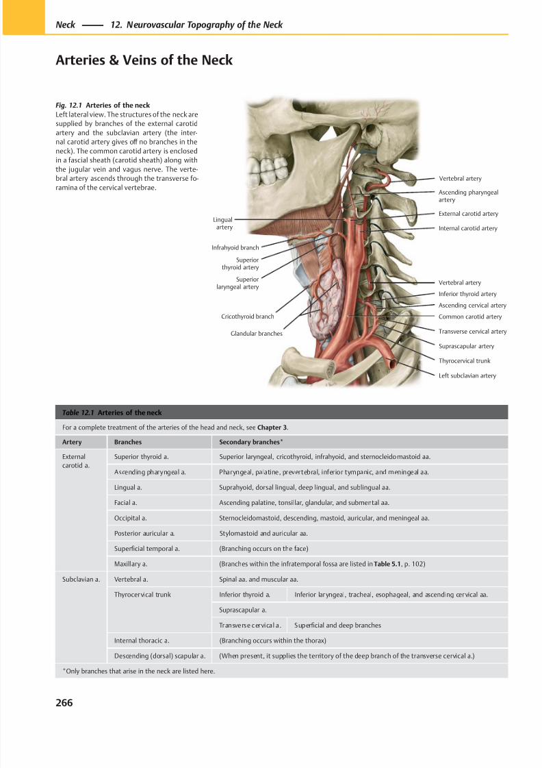
8/15/2019 Head and Neck Anatomy for Dental Medicine - Thieme; (January 26, 2010)
http://slidepdf.com/reader/full/head-and-neck-anatomy-for-dental-medicine-thieme-january-26-2010 279/384
Ascending pharyngealartery
Superiorlaryngeal artery
Infrahyoid branch
Cricothyroid branch
External carotid artery
Internal carotid artery
Vertebral artery
Common carotid artery
Lingualartery
Left subclavian artery
Thyrocervical trunk
Glandular branches
Superior
thyroid artery
Vertebral artery
Inferior thyroid artery
Ascending cervical artery
Transverse cervical artery
Suprascapular artery
Table 12.1 Arteries of the neck
For a complete treatment of the arteries of the head and neck, see Chapter 3.
Artery Branches Secondary branches*
External
carotid a.
Superior thyroid a. Superior laryngeal, cricothyroid, infrahyoid, and sternocleidomastoid aa.
Ascending pharyngeal a. Pharyngeal, palatine, prevertebral, inferior tympanic, and meningeal aa.
Lingual a. Suprahyoid, dorsal lingual, deep lingual, and sublingual aa.
Facial a. Ascending palatine, tonsillar, glandular, and submental aa.
Occipital a. Sternocleidomastoid, descending, mastoid, auricular, and meningeal aa.
Posterior auricular a. Stylomastoid and auricular aa.
Superficial temporal a. (Branching occurs on the face)
Maxillary a. (Branches within the infratemporal fossa are listed in Table 5.1, p. 102)
Subclavian a. Vertebral a. Spinal aa. and muscular aa.
Thyrocervical trunk Inferior thyroid a. Inferior laryngeal, tracheal, esophageal, and ascending cervical aa.
Suprascapular a.
Transverse cervical a. Superficial and deep branches
Internal thoracic a. (Branching occurs within the thorax)
Descending (dorsal) scapular a. (When present, it supplies the territory of the deep branch of the transverse cervical a.)
*Only branches that arise in the neck are listed here.
Fig. 12.1 Arteries of the neck
Left lateral view. The structures of the neck are
supplied by branches of the external carotid
artery and the subclavian artery (the inter-nal carotid artery gives off no branches in the
neck). The common carotid artery is enclosed
in a fascial sheath (carotid sheath) along with
the jugular vein and vagus nerve. The verte-
bral artery ascends through the transverse fo-
ramina of the cervical vertebrae.
266
Neck 12. Neurovascular Topography of the Neck
Arteries & Veins of the Neck
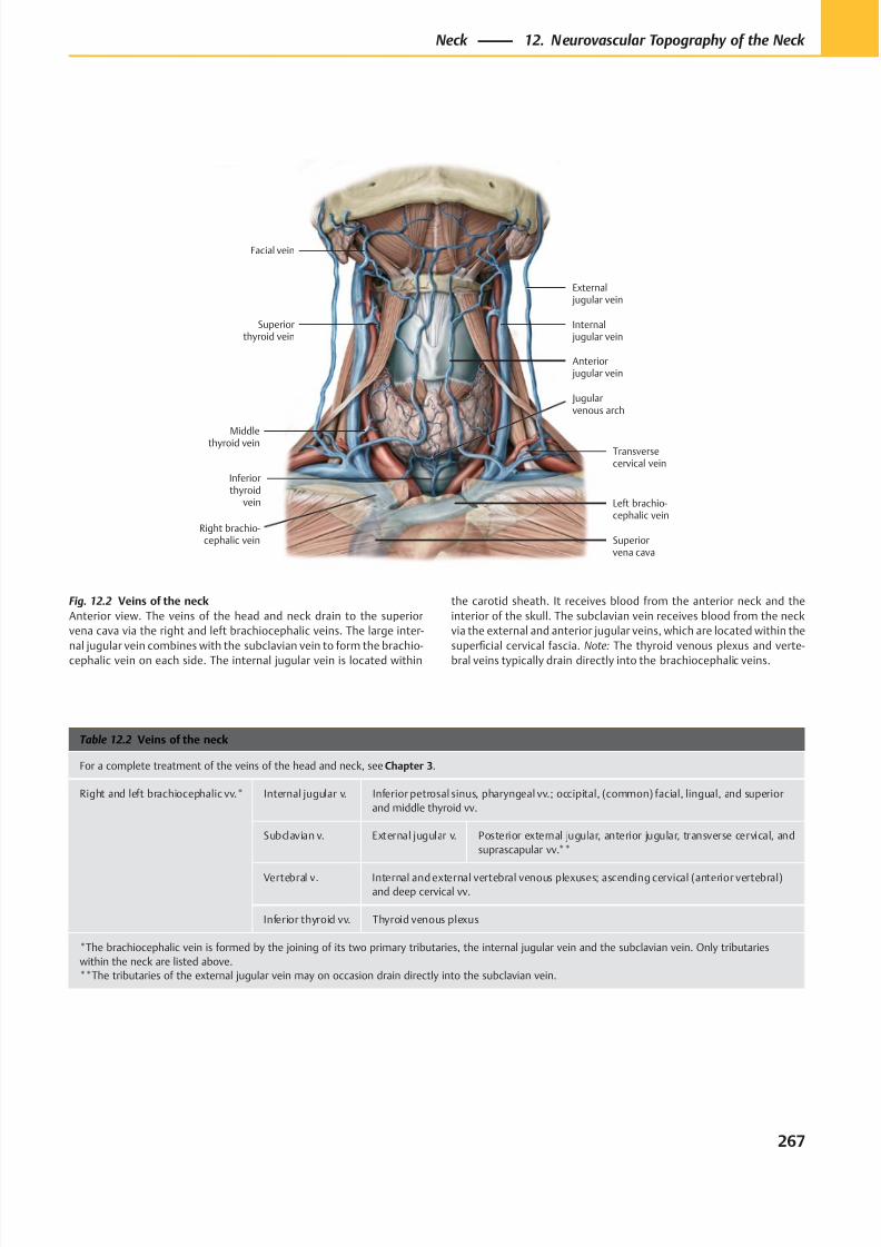
8/15/2019 Head and Neck Anatomy for Dental Medicine - Thieme; (January 26, 2010)
http://slidepdf.com/reader/full/head-and-neck-anatomy-for-dental-medicine-thieme-january-26-2010 280/384
Middlethyroid vein
Superiorthyroid vein
Facial vein
External jugular vein
Internal jugular vein
Anterior jugular vein
Transversecervical vein
Right brachio-cephalic vein
Jugularvenous arch
Left brachio-cephalic vein
Inferiorthyroid
vein
Superiorvena cava
Table 12.2 Veins of the neck
For a complete treatment of the veins of the head and neck, see Chapter 3.
Right and left brachiocephalic vv.* Internal jugular v. Inferior petrosal sinus, pharyngeal vv.; occipital, (common) facial, lingual, and superior
and middle thyroid vv.
Subclavian v. External jugular v. Posterior external jugular, anterior jugular, transverse cervical, and
suprascapular vv.**
Vertebral v. Internal and external vertebral venous plexuses; ascending cervical (anterior vertebral)
and deep cervical vv.
Inferior thyroid vv. Thyroid venous plexus
*The brachiocephalic vein is formed by the joining of its two primary tributaries, the internal jugular vein and the subclavian vein. Only tributaries
within the neck are listed above.
**The tributaries of the external jugular vein may on occasion drain directly into the subclavian vein.
Fig. 12.2 Veins of the neck
Anterior view. The veins of the head and neck drain to the superior
vena cava via the right and left brachiocephalic veins. The large inter-
nal jugular vein combines with the subclavian vein to form the brachio-
cephalic vein on each side. The internal jugular vein is located within
the carotid sheath. It receives blood from the anterior neck and the
interior of the skull. The subclavian vein receives blood from the neck
via the external and anterior jugular veins, which are located within the
superficial cervical fascia. Note: The thyroid venous plexus and verte-
bral veins typically drain directly into the brachiocephalic veins.
267
Neck 12. Neurovascular Topography of the Neck
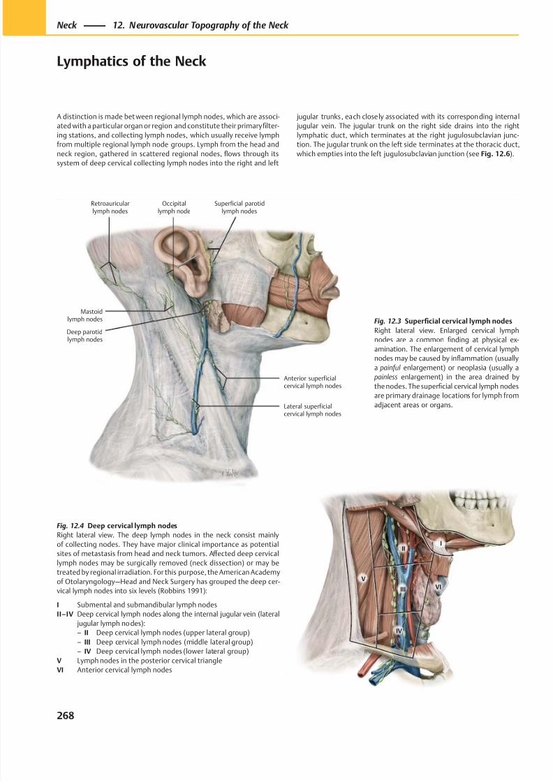
8/15/2019 Head and Neck Anatomy for Dental Medicine - Thieme; (January 26, 2010)
http://slidepdf.com/reader/full/head-and-neck-anatomy-for-dental-medicine-thieme-january-26-2010 281/384
Lateral superficialcervical lymph nodes
Anterior superficialcervical lymph nodes
Deep parotidlymph nodes
Superficial parotidlymph nodes
Retroauricularlymph nodes
Occipitallymph node
Mastoidlymph nodes
II
V
III
IV
I
VI
Fig. 12.4 Deep cervical lymph nodes
Right lateral view. The deep lymph nodes in the neck consist mainly
of collecting nodes. They have major clinical importance as potentialsites of metastasis from head and neck tumors. Aff ected deep cervical
lymph nodes may be surgically removed (neck dissection) or may be
treated by regional irradiation. For this purpose, the American Academy
of Otolaryngology—Head and Neck Surgery has grouped the deep cer-
vical lymph nodes into six levels (Robbins 1991):
I Submental and submandibular lymph nodes
II–IV Deep cervical lymph nodes along the internal jugular vein (lateral
jugular lymph nodes):
– II Deep cervical lymph nodes (upper lateral group)
– III Deep cervical lymph nodes (middle lateral group)
– IV Deep cervical lymph nodes (lower lateral group)
V Lymph nodes in the posterior cervical triangle
VI Anterior cervical lymph nodes
A distinction is made bet ween regional lymph nodes, which are associ-
ated with a particular organ or region and constitute their primary filter-
ing stations, and collecting lymph nodes, which usually receive lymphfrom multiple regional lymph node groups. Lymph from the head and
neck region, gathered in scattered regional nodes, flows through its
system of deep cervical collecting lymph nodes into the right and left
jugular trunks, each closely associated with its corresponding internal
jugular vein. The jugular trunk on the right side drains into the right
lymphatic duct, which terminates at the right jugulosubclavian junc-tion. The jugular trunk on the left side terminates at the thoracic duct,
which empties into the left jugulosubclavian junction (see Fig. 12.6).
Fig. 12.3 Superficial cervical lymph nodes
Right lateral view. Enlarged cervical lymph
nodes are a common finding at physical ex-
amination. The enlargement of cervical lymph
nodes may be caused by inflammation (usually
a painful enlargement) or neoplasia (usually a
painless enlargement) in the area drained by
the nodes. The superficial cervical lymph nodes
are primary drainage locations for lymph from
adjacent areas or organs.
268
Neck 12. Neurovascular Topography of the Neck
Lymphatics of the Neck
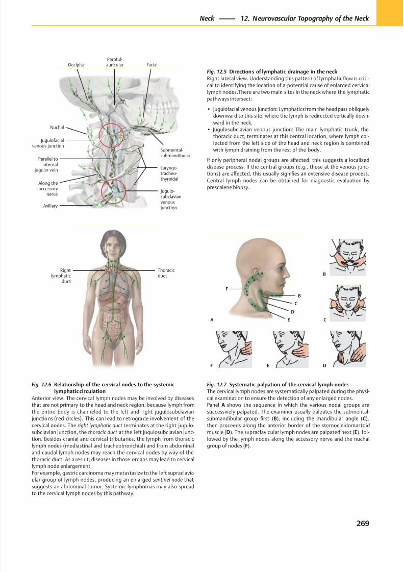
8/15/2019 Head and Neck Anatomy for Dental Medicine - Thieme; (January 26, 2010)
http://slidepdf.com/reader/full/head-and-neck-anatomy-for-dental-medicine-thieme-january-26-2010 282/384
B
C
F
D
E C
B
DEF
A
Thoracicduct
Rightlymphatic
duct
Jugulo-subclavianvenous junction
Jugulofacialvenous junction
Axillary
Laryngo-tracheo-thyroidal
Nuchal
Along theaccessory
nerve
Parallel tointernal
jugular vein
OccipitalParotid-auricular Facial
Submental-submandibular
Fig. 12.6 Relationship of the cervical nodes to the systemic
lymphatic circulation
Anterior view. The cervical lymph nodes may be involved by diseasesthat are not primary to the head and neck region, because lymph from
the entire body is channeled to the left and right jugulosubclavian
junctions (red circles). This can lead to retrograde involvement of the
cervical nodes. The right lymphatic duct terminates at the right jugulo-
subclavian junction, the thoracic duct at the left jugulosubclavian junc-
tion. Besides cranial and cervical tributaries, the lymph from thoracic
lymph nodes (mediastinal and tracheobronchial) and from abdominal
and caudal lymph nodes may reach the cervical nodes by way of the
thoracic duct. As a result, diseases in those organs may lead to cervical
lymph node enlargement.
For example, gastric carcinoma may metastasize to the left supraclavic-
ular group of lymph nodes, producing an enlarged sentinel node that
suggests an abdominal tumor. Systemic lymphomas may also spread
to the cervical lymph nodes by this pathway.
Fig. 12.5 Directions of lymphatic drainage in the neck
Right lateral view. Understanding this pattern of lymphatic flow is criti-
cal to identifying the location of a potential cause of enlarged cervical
lymph nodes.There are two main sites in the neck where the lymphatic
pathways intersect:
• Jugulofacial venous junction: Lymphatics from the head pass obliquely
downward to this site, where the lymph is redirected vertically down-
ward in the neck.
• Jugulosubclavian venous junction: The main lymphatic trunk, the
thoracic duct, terminates at this central location, where lymph col-
lected from the left side of the head and neck region is combined
with lymph draining from the rest of the body.
If only peripheral nodal groups are aff ected, this suggests a localized
disease process. If the central groups (e.g., those at the venous junc-
tions) are aff ected, this usually signifies an extensive disease process.
Central lymph nodes can be obtained for diagnostic evaluation by
prescalene biopsy.
Fig. 12.7 Systematic palpation of the cervical lymph nodes
The cervical lymph nodes are systematically palpated during the physi-
cal examination to ensure the detection of any enlarged nodes.Panel A shows the sequence in which the various nodal groups are
successively palpated. The examiner usually palpates the submental-
submandibular group first (B), including the mandibular angle (C),
then proceeds along the anterior border of the sternocleidomastoid
muscle (D). The supraclavicular lymph nodes are palpated next (E), fol-
lowed by the lymph nodes along the accessory nerve and the nuchal
group of nodes (F).
269
Neck 12. Neurovascular Topography of the Neck
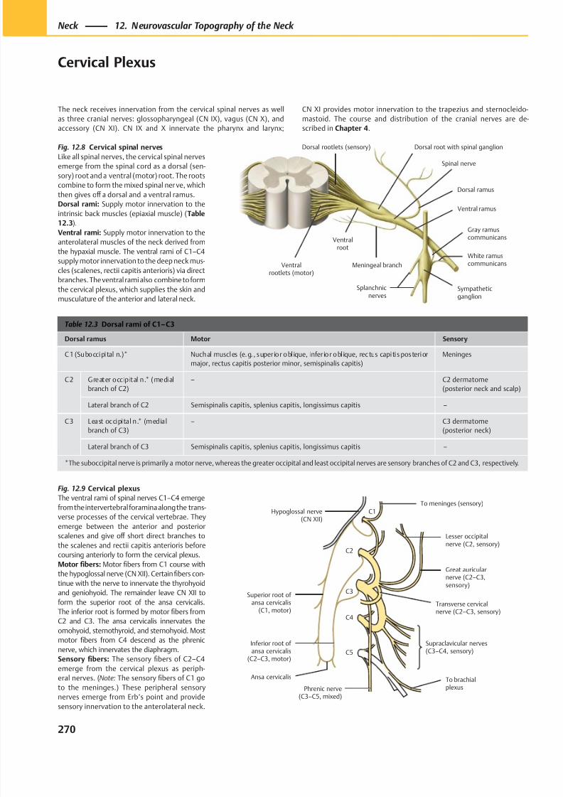
8/15/2019 Head and Neck Anatomy for Dental Medicine - Thieme; (January 26, 2010)
http://slidepdf.com/reader/full/head-and-neck-anatomy-for-dental-medicine-thieme-january-26-2010 283/384
Ventralrootlets (motor)
Meningeal branch
Ventral ramus
Splanchnicnerves
Sympatheticganglion
White ramuscommunicans
Gray ramuscommunicans
Dorsal ramus
Dorsal root with spinal ganglionDorsal rootlets (sensory)
Ventralroot
Spinal nerve
Lesser occipitalnerve (C2, sensory)
Hypoglossal nerve(CN XII)
Superior root of ansa cervicalis
(C1, motor)
Inferior root of ansa cervicalis
(C2–C3, motor)
Phrenic nerve
(C3–C5, mixed)
Supraclavicular nerves(C3–C4, sensory)
Transverse cervicalnerve (C2–C3, sensory)
Great auricularnerve (C2–C3,sensory)
To brachialplexus
C1
C2
C3
C4
C5
To meninges (sensory)
Ansa cervicalis
Table 12.3 Dorsal rami of C1– C3
Dorsal ramus Motor Sensory
C1 (Suboccipital n.)* Nuchal muscles (e.g. , superior obl ique, infer ior obl ique, rectus capitis posterior
major, rectus capitis posterior minor, semispinalis capitis)
Meninges
C2 Greater occipital n.* (medial
branch of C2)
– C2 dermatome
(posterior neck and scalp)
Lateral branch of C2 Semispinalis capitis, splenius capitis, longissimus capitis –
C3 Least occipital n.* (medial
branch of C3)
– C3 dermatome
(posterior neck)
Lateral branch of C3 Semispinalis capitis, splenius capitis, longissimus capitis –
*The suboccipital nerve is primarily a motor nerve, whereas the greater occipital and least occipital nerves are sensory branches of C2 and C3, respectively.
Fig. 12.8 Cervical spinal nerves
Like all spinal nerves, the cervical spinal nerves
emerge from the spinal cord as a dorsal (sen-
sory) root and a ventral (motor) root. The roots
combine to form the mixed spinal ner ve, which
then gives off a dorsal and a ventral ramus.
Dorsal rami: Supply motor innervation to the
intrinsic back muscles (epiaxial muscle) (Table
12.3).
Ventral rami: Supply motor innervation to the
anterolateral muscles of the neck derived from
the hypaxial muscle. The ventral rami of C1–C4
supply motor innervation to the deep neck mus-
cles (scalenes, rectii capitis anterioris) via direct
branches. The ventral rami also combine to formthe cervical plexus, which supplies the skin and
musculature of the anterior and lateral neck.
Fig. 12.9 Cervical plexus
The ventral rami of spinal nerves C1–C4 emerge
from the intervertebral foramina along the trans-
verse processes of the cervical vertebrae. They
emerge between the anterior and posterior
scalenes and give off short direct branches to
the scalenes and rectii capitis anterioris before
coursing anteriorly to form the cervical plexus.Motor fibers: Motor fibers from C1 course with
the hypoglossal nerve (CN XII). Certain fibers con-
tinue with the nerve to innervate the thyrohyoid
and geniohyoid. The remainder leave CN XII to
form the superior root of the ansa cervicalis.
The inferior root is formed by motor fibers from
C2 and C3. The ansa cervicalis innervates the
omohyoid, sternothyroid, and sternohyoid. Most
motor fibers from C4 descend as the phrenic
nerve, which innervates the diaphragm.
Sensory fibers: The sensory fibers of C2–C4
emerge from the cervical plexus as periph-
eral nerves. (Note: The sensory fibers of C1 go
to the meninges.) These peripheral sensory
nerves emerge from Erb’s point and providesensory innervation to the anterolateral neck.
270
Neck 12. Neurovascular Topography of the Neck
Cervical Plexus
The neck receives innervation from the cervical spinal nerves as well
as three cranial nerves: glossopharyngeal (CN IX), vagus (CN X), and
accessory (CN XI). CN IX and X innervate the pharynx and larynx;
CN XI provides motor innervation to the trapezius and sternocleido-
mastoid. The course and distribution of the cranial nerves are de-
scribed in Chapter 4.
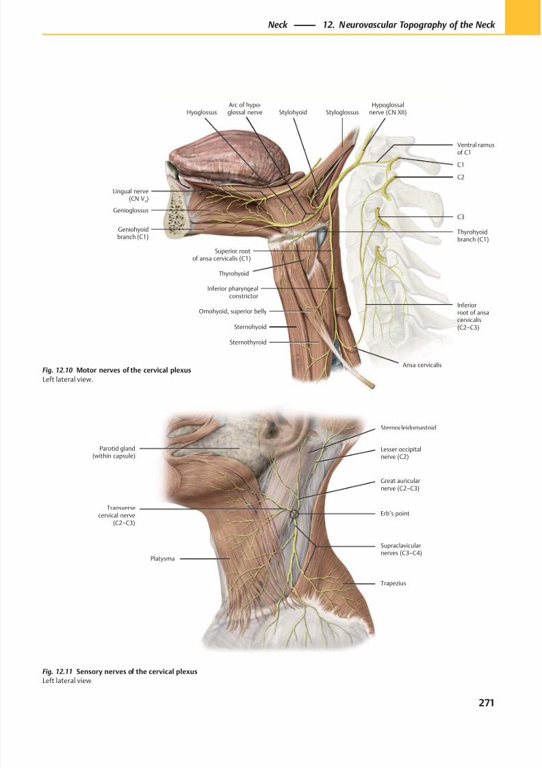
8/15/2019 Head and Neck Anatomy for Dental Medicine - Thieme; (January 26, 2010)
http://slidepdf.com/reader/full/head-and-neck-anatomy-for-dental-medicine-thieme-january-26-2010 284/384
Lesser occipitalnerve (C2)
Great auricularnerve (C2–C3)
Erb’s point
Supraclavicularnerves (C3–C4)
Sternocleidomastoid
Trapezius
Parotid gland(within capsule)
Transversecervical nerve
(C2–C3)
Platysma
Genioglossus
Geniohyoidbranch (C1)
Hyoglossus
Sternohyoid
Superior rootof ansa cervicalis (C1)
Omohyoid, superior belly
Sternothyroid
Inferior pharyngealconstrictor
Inferiorroot of ansacervicalis(C2–C3)
C3
C1
Ventral ramusof C1
StylohyoidHypoglossal
nerve (CN XII)Styloglossus
C2
Lingual nerve(CN V
3)
Thyrohyoid
Thyrohyoidbranch (C1)
Arc of hypo-glossal nerve
Ansa cervicalisFig. 12.10 Motor nerves of the cervical plexus
Left lateral view.
Fig. 12.11 Sensory nerves of the cervical plexusLeft lateral view.
271
Neck 12. Neurovascular Topography of the Neck
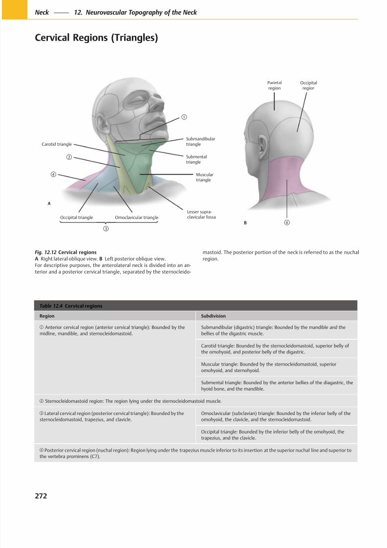
8/15/2019 Head and Neck Anatomy for Dental Medicine - Thieme; (January 26, 2010)
http://slidepdf.com/reader/full/head-and-neck-anatomy-for-dental-medicine-thieme-january-26-2010 285/384
Occipital triangle Omoclavicular triangle
Lesser supra-clavicular fossa
Musculartriangle
Carotid triangle
Submentaltriangle
Submandibulartriangle
A
Parietalregion
B
Occipitalregion
Table 12.4 Cervical regions
Region Subdivision
Anterior cervical region (anterior cervical triangle): Bounded by the
midline, mandible, and sternocleidomastoid.
Submandibular (digastric) triangle: Bounded by the mandible and the
bellies of the digastric muscle.
Carotid triangle: Bounded by the sternocleidomastoid, superior belly of
the omohyoid, and posterior belly of the digastric.
Muscular triangle: Bounded by the sternocleidomastoid, superior
omohyoid, and sternohyoid.
Submental triangle: Bounded by the anterior bellies of the diagastric, thehyoid bone, and the mandible.
Sternocleidomastoid region: The region lying under the sternocleidomastoid muscle.
Lateral cervical region (posterior cervical triangle): Bounded by the
sternocleidomastoid, trapezius, and clavicle.
Omoclavicular (subclavian) triangle: Bounded by the inferior belly of the
omohyoid, the clavicle, and the sternocleidomastoid.
Occipital triangle: Bounded by the inferior belly of the omohyoid, the
trapezius, and the clavicle.
Posterior cervical region (nuchal region): Region lying under the trapezius muscle inferior to its insertion at the superior nuchal line and superior to
the vertebra prominens (C7).
Fig. 12.12 Cervical regions
A Right lateral oblique view. B Left posterior oblique view.
For descriptive purposes, the anterolateral neck is divided into an an-
terior and a posterior cervical triangle, separated by the sternocleido-
mastoid. The posterior portion of the neck is referred to as the nuchal
region.
272
Neck 12. Neurovascular Topography of the Neck
Cervical Regions (Triangles)
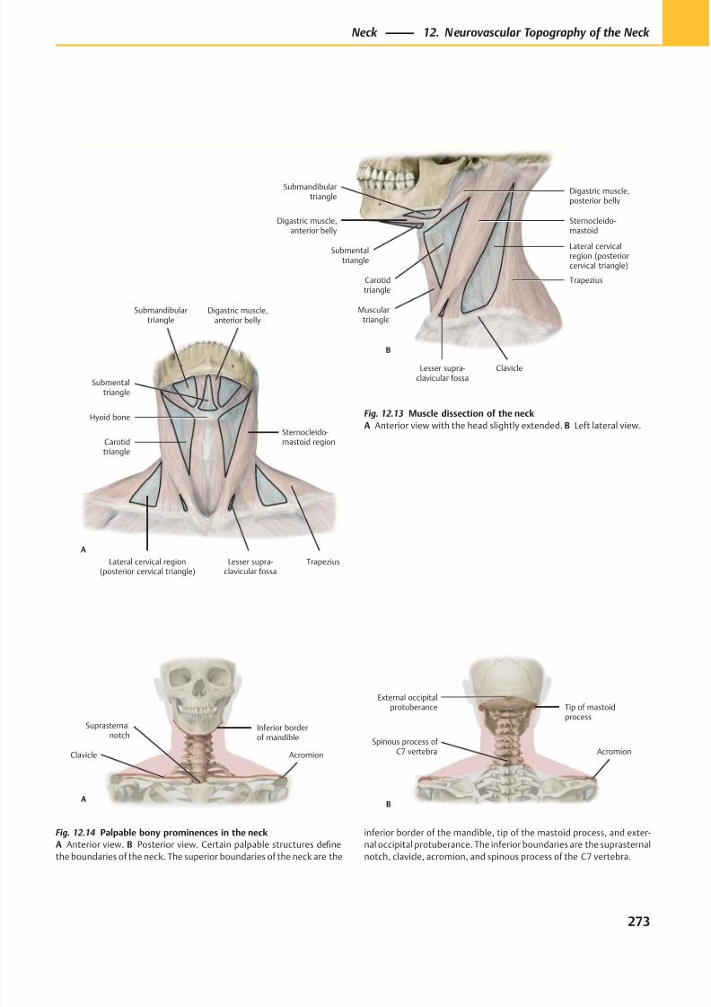
8/15/2019 Head and Neck Anatomy for Dental Medicine - Thieme; (January 26, 2010)
http://slidepdf.com/reader/full/head-and-neck-anatomy-for-dental-medicine-thieme-january-26-2010 286/384
Lateral cervical region(posterior cervical triangle)
Lesser supra-clavicular fossa
Trapezius
Sternocleido-mastoid regionCarotid
triangle
Hyoid bone
Submentaltriangle
Submandibulartriangle
A
Digastric muscle,anterior belly
Submentaltriangle
Carotidtriangle
Musculartriangle
Lesser supra-clavicular fossa
Clavicle
Trapezius
Lateral cervicalregion (posteriorcervical triangle)
Sternocleido-mastoid
Digastric muscle,posterior belly
B
Digastric muscle,anterior belly
Submandibulartriangle
AcromionSpinous process of
C7 vertebra
Tip of mastoidprocess
External occipital
protuberance
B
Suprasternalnotch
AcromionClavicle
Inferior borderof mandible
A
Fig. 12.13 Muscle dissection of the neck
A Anterior view with the head slightly extended. B Left lateral view.
Fig. 12.14 Palpable bony prominences in the neck
A Anterior view. B Posterior view. Certain palpable structures define
the boundaries of the neck. The superior boundaries of the neck are the
inferior border of the mandible, tip of the mastoid process, and exter-
nal occipital protuberance. The inferior boundaries are the suprasternal
notch, clavicle, acromion, and spinous process of the C7 vertebra.
273
Neck 12. Neurovascular Topography of the Neck
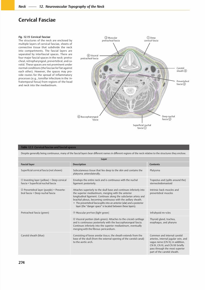
8/15/2019 Head and Neck Anatomy for Dental Medicine - Thieme; (January 26, 2010)
http://slidepdf.com/reader/full/head-and-neck-anatomy-for-dental-medicine-thieme-january-26-2010 287/384
Visceralpretracheal fascia
Carotidsheath
Prevertebralfascia
Muscularpretracheal fascia
Deepcervical fascia
Buccopharyngealfascia
Deep nuchalfascia
Superficial nuchalfascia
Fig. 12.15 Cervical fasciae
The structures of the neck are enclosed by
multiple layers of cervical fasciae, sheets of
connective tissue that subdivide the neck
into compartments. The fascial layers areseparated by interfascial spaces. There are
four major fascial spaces in the neck: pretra-
cheal, retropharyngeal, prevertebral, and ca-
rotid. These spaces are not prominent under
normal conditions (the fasciae lie f lat against
each other). However, the spaces may pro-
vide routes for the spread of inflammatory
processes (e.g., tonsillar infections in the in-
fratemporal fossa) from regions of the head
and neck into the mediastinum.
Table 12.5 Cervical fasciae and fascial spaces
Layer
Fascial layer Description Contents
Subcutaneous tissue that lies deep to the skin and contains the
platysma anterolaterally.
Platysma
Investing layer (yellow) = Deep cervical
Envelops the entire neck and is continuous with the nuchal
ligament posteriorly.
Trapezius and (splits around the)
sternocleidomastoid
Prevertebral layer (purple) = Preverte-
bral fascia + Deep nuchal fascia
Attaches superiorly to the skull base and continues inferiorly into
the superior mediastinum, merging with the anterior
longitudinal ligament. Continues along the subclavian artery and
brachial plexus, becoming continuous with the axillary sheath.
layer (the “danger space” is located between these layers).
Intrinsic back muscles and
prevertebral muscles
Pretracheal fascia (green) Muscular portion (light green) Infrahyoid muscles
Visceral portion (dark green): Attaches to the cricoid cartilage
and is continuous posteriorly with the buccopharyngeal fascia.
Continues inferiorly into the superior mediastinum, eventually
Thyroid gland, trachea,
esophagus, and pharynx
Carotid sheath (blue) Consisting of loose areolar tissue, the sheath extends from the
base of the skull (from the external opening of the carotid canal)
to the aortic arch.
Common and internal carotid
arteries, internal jugular vein, and
vagus nerve (CN X); in addition,
pass through the most superior
part of the carotid sheath.
274
Neck 12. Neurovascular Topography of the Neck
Cervical Fasciae
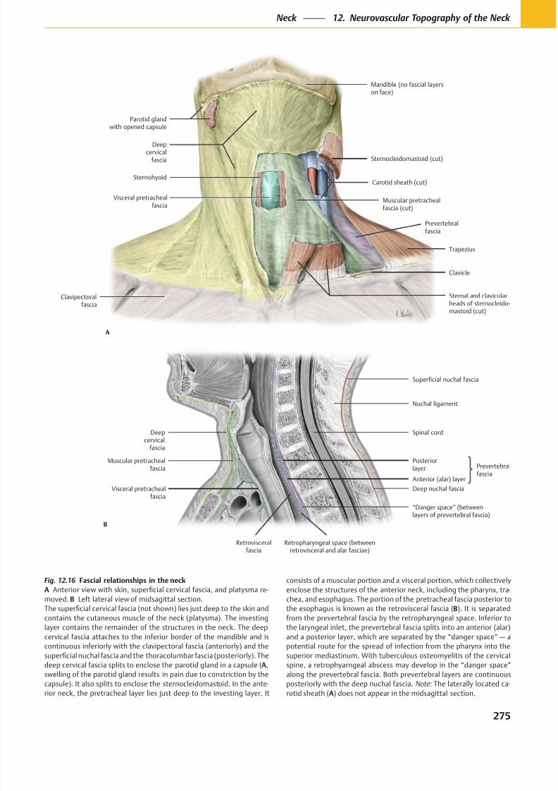
8/15/2019 Head and Neck Anatomy for Dental Medicine - Thieme; (January 26, 2010)
http://slidepdf.com/reader/full/head-and-neck-anatomy-for-dental-medicine-thieme-january-26-2010 288/384
Sternohyoid
Trapezius
Parotid glandwith opened capsule
Sternocleidomastoid (cut)
Carotid sheath (cut)
Prevertebralfascia
Muscular pretrachealfascia (cut)
Deepcervical
fascia
Visceral pretrachealfascia
Mandible (no fascial layerson face)
Clavicle
A
Clavipectoralfascia
Sternal and clavicularheads of sternocleido-mastoid (cut)
Visceral pretrachealfascia
Posteriorlayer
Muscular pretrachealfascia
Deepcervical
fascia
Nuchal ligament
Spinal cord
“Danger space” (betweenlayers of prevertebral fascia)
B
Retrovisceral
fascia
Retropharyngeal space (between
retrovisceral and alar fasciae)
Anterior (alar) layer
Deep nuchal fascia
Prevertebralfascia
Superficial nuchal fascia
Fig. 12.16 Fascial relationships in the neck
A -
B
A,
-
-
B
Note: -
A
275
Neck 12. Neurovascular Topography of the Neck
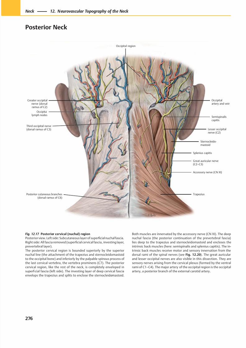
8/15/2019 Head and Neck Anatomy for Dental Medicine - Thieme; (January 26, 2010)
http://slidepdf.com/reader/full/head-and-neck-anatomy-for-dental-medicine-thieme-january-26-2010 289/384
Posterior cutaneous branches(dorsal ramus of C6)
Occipitallymph nodes
Trapezius
Splenius capitis
Sternocleido-mastoid
Great auricular nerve(C2–C3)
Lesser occipitalnerve (C2)
Semispinaliscapitis
Occipitalartery and vein
Occipital region
Accessory nerve (CN XI)
Third occipital nerve(dorsal ramus of C3)
Greater occipitalnerve (dorsalramus of C2)
Fig. 12.17 Posterior cervical (nuchal) region
Posterior view. Left side: Subcutaneous layer of superficial nuchal fascia.
Right side: All fascia removed (superfi
cial cervical fascia, investing layer,prevertebral layer).
The posterior cervical region is bounded superiorly by the superior
nuchal line (the attachment of the trapezius and sternocleidomastoid
to the occipital bone) and inferiorly by the palpable spinous process of
the last cervical vertebra, the vertebra prominens (C7). The posterior
cervical region, like the rest of the neck, is completely enveloped in
superficial fascia (left side). The investing layer of deep cervical fascia
envelops the trapezius and splits to enclose the sternocleidomastoid.
Both muscles are innervated by the accessory nerve (CN XI). The deep
nuchal fascia (the posterior continuation of the prevertebral fascia)
lies deep to the trapezius and sternocleidomastoid and encloses theintrinsic back muscles (here: semispinalis and splenius capitis). The in-
trinsic back muscles receive motor and sensory innervation from the
dorsal rami of the spinal nerves (see Fig. 12.20). The great auricular
and lesser occipital nerves are also visible in this dissection. They are
sensory nerves arising from the cervical plexus (formed by the ventral
rami of C1–C4). The major artery of the occipital region is the occipital
artery, a posterior branch of the external carotid artery.
276
Neck 12. Neurovascular Topography of the Neck
Posterior Neck
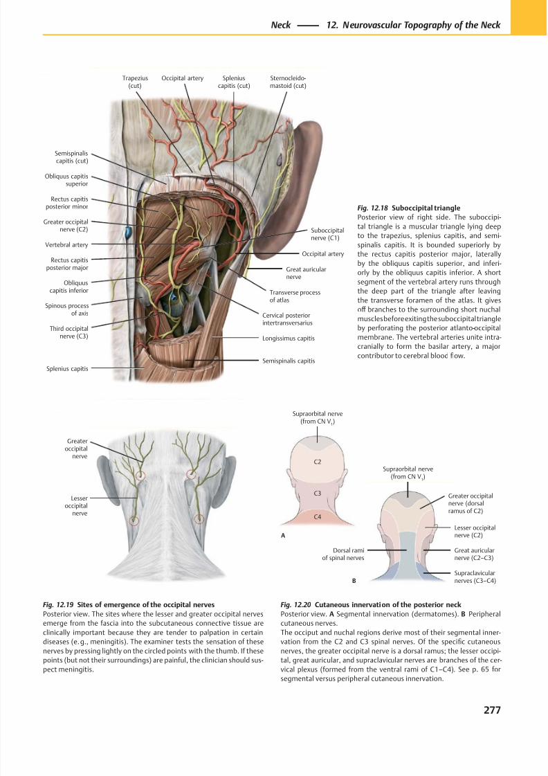
8/15/2019 Head and Neck Anatomy for Dental Medicine - Thieme; (January 26, 2010)
http://slidepdf.com/reader/full/head-and-neck-anatomy-for-dental-medicine-thieme-january-26-2010 290/384
Occipital artery
Vertebral artery
Rectus capitisposterior minor
Greater occipitalnerve (C2)
Rectus capitisposterior major
Obliquuscapitis inferior
Third occipitalnerve (C3)
Cervical posteriorintertransversarius
Longissimus capitis
Great auricularnerve
Obliquus capitissuperior
Occipital artery
Semispinaliscapitis (cut)
Sternocleido-mastoid (cut)
Spleniuscapitis (cut)
Semispinalis capitis
Transverse processof atlas
Spinous processof axis
Splenius capitis
Suboccipitalnerve (C1)
Trapezius(cut)
Lesseroccipital
nerve
Greateroccipital
nerve
Supraclavicularnerves (C3–C4)
Great auricularnerve (C2–C3)
Lesser occipitalnerve (C2)
Greater occipitalnerve (dorsalramus of C2)
Supraorbital nerve(from CN V
1)
C4
C3
C2
Supraorbital nerve(from CN V
1)
A
B
Dorsal ramiof spinal nerves
Fig. 12.18 Suboccipital triangle
Posterior view of right side. The suboccipi-
tal triangle is a muscular triangle lying deep
to the trapezius, splenius capitis, and semi-
spinalis capitis. It is bounded superiorly by
the rectus capitis posterior major, laterally
by the obliquus capitis superior, and inferi-
orly by the obliquus capitis inferior. A shortsegment of the vertebral artery runs through
the deep part of the triangle after leaving
the transverse foramen of the atlas. It gives
off branches to the surrounding short nuchal
muscles before exiting the suboccipital triangle
by perforating the posterior atlanto-occipital
membrane. The vertebral arteries unite intra-
cranially to form the basilar artery, a major
contributor to cerebral blood flow.
Fig. 12.20 Cutaneous innervation of the posterior neck
Posterior view. A Segmental innervation (dermatomes). B Peripheral
cutaneous nerves.
The occiput and nuchal regions derive most of their segmental inner-
vation from the C2 and C3 spinal nerves. Of the specific cutaneous
nerves, the greater occipital nerve is a dorsal ramus; the lesser occipi-
tal, great auricular, and supraclavicular nerves are branches of the cer-
vical plexus (formed from the ventral rami of C1–C4). See p. 65 for
segmental versus peripheral cutaneous innervation.
Fig. 12.19 Sites of emergence of the occipital nerves
Posterior view. The sites where the lesser and greater occipital nerves
emerge from the fascia into the subcutaneous connective tissue are
clinically important because they are tender to palpation in certain
diseases (e. g., meningitis). The examiner tests the sensation of these
nerves by pressing lightly on the circled points with the thumb. If these
points (but not their surroundings) are painful, the clinician should sus-
pect meningitis.
277
Neck 12. Neurovascular Topography of the Neck
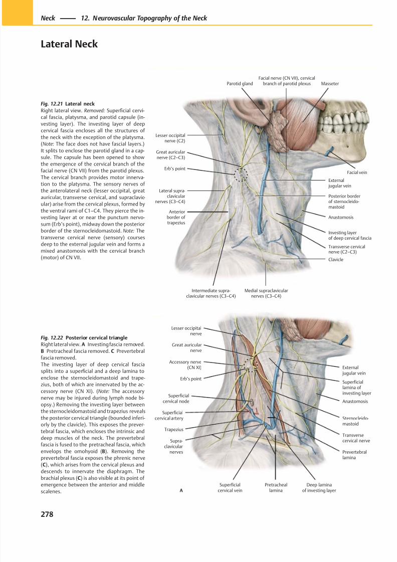
8/15/2019 Head and Neck Anatomy for Dental Medicine - Thieme; (January 26, 2010)
http://slidepdf.com/reader/full/head-and-neck-anatomy-for-dental-medicine-thieme-january-26-2010 291/384
Posterior borderof sternocleido-mastoid
Great auricularnerve (C2–C3)
Lateral supra-
clavicularnerves (C3–C4)
Anteriorborder of trapezius
Erb’s point
Intermediate supra-
clavicular nerves (C3–C4)
Medial supraclavicular
nerves (C3–C4)
Clavicle
External jugular vein
Investing layerof deep cervical fascia
Anastomosis
Parotid gland
Transverse cervicalnerve (C2–C3)
Lesser occipitalnerve (C2)
MasseterFacial nerve (CN VII), cervical
branch of parotid plexus
Facial vein
Superficialcervical node
Accessory nerve(CN XI)
Trapezius
Superficialcervical artery
Superficial
cervical vein
Transversecervical nerve
Sternocleido-mastoid
Great auricularnerve
Supra-clavicular
nerves
Pretracheal
lamina
External jugular vein
Anastomosis
Lesser occipitalnerve
Erb’s pointSuperficiallamina of
investing layer
Prevertebrallamina
A
Deep lamina
of investing layer
Fig. 12.22 Posterior cervical triangle
Right lateral view. A Investing fascia removed.
B Pretracheal fascia removed. C Prevertebral
fascia removed.
The investing layer of deep cervical fascia
splits into a superficial and a deep lamina to
enclose the sternocleidomastoid and trape-
zius, both of which are innervated by the ac-
cessory nerve (CN XI). (Note: The accessorynerve may be injured during lymph node bi-
opsy.) Removing the investing layer between
the sternocleidomastoid and trapezius reveals
the posterior cervical triangle (bounded inferi-
orly by the clavicle). This exposes the prever-
tebral fascia, which encloses the intrinsic and
deep muscles of the neck. The prevertebral
fascia is fused to the pretracheal fascia, which
envelops the omohyoid (B). Removing the
prevertebral fascia exposes the phrenic nerve
(C), which arises from the cervical plexus and
descends to innervate the diaphragm. The
brachial plexus (C) is also visible at its point of
emergence between the anterior and middle
scalenes.
Fig. 12.21 Lateral neck
Right lateral view. Removed: Superficial cervi-
cal fascia, platysma, and parotid capsule (in-
vesting layer). The investing layer of deep
cervical fascia encloses all the structures of
the neck with the exception of the platysma.
(Note: The face does not have fascial layers.)
It splits to enclose the parotid gland in a cap-
sule. The capsule has been opened to show
the emergence of the cervical branch of the
facial nerve (CN VII) from the parotid plexus.
The cervical branch provides motor innerva-
tion to the platysma. The sensory nerves of
the anterolateral neck (lesser occipital, great
auricular, transverse cervical, and supraclavic-ular) arise from the cervical plexus, formed by
the ventral rami of C1–C4. They pierce the in-
vesting layer at or near the punctum nervo-
sum (Erb’s point), midway down the posterior
border of the sternocleidomastoid. Note: The
transverse cervical nerve (sensory) courses
deep to the external jugular vein and forms a
mixed anastomosis with the cervical branch
(motor) of CN VII.
278
Neck 12. Neurovascular Topography of the Neck
Lateral Neck
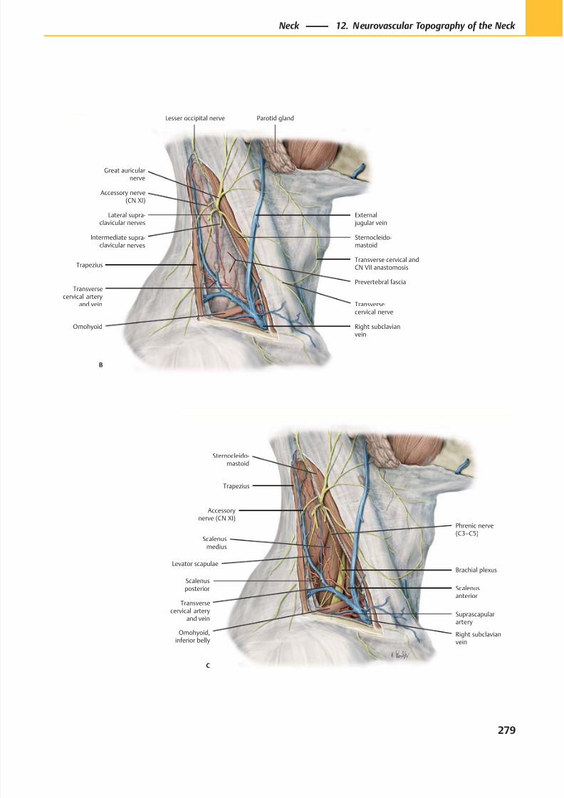
8/15/2019 Head and Neck Anatomy for Dental Medicine - Thieme; (January 26, 2010)
http://slidepdf.com/reader/full/head-and-neck-anatomy-for-dental-medicine-thieme-january-26-2010 292/384
Levator scapulae
Scalenusposterior
Scalenusmedius
Scalenusanterior
Omohyoid,inferior belly
Transversecervical artery
and vein
Brachial plexus
C
Suprascapularartery
Accessorynerve (CN XI)
Right subclavianvein
Phrenic nerve(C3–C5)
Trapezius
Sternocleido-mastoid
External jugular vein
Lateral supra-clavicular nerves
Trapezius
Intermediate supra-clavicular nerves
Right subclavianvein
Transversecervical artery
and vein
Transverse cervical andCN VII anastomosis
Prevertebral fascia
Sternocleido-mastoid
Parotid gland
Accessory nerve(CN XI)
Transversecervical nerve
B
Lesser occipital nerve
Great auricularnerve
Omohyoid
279
Neck 12. Neurovascular Topography of the Neck
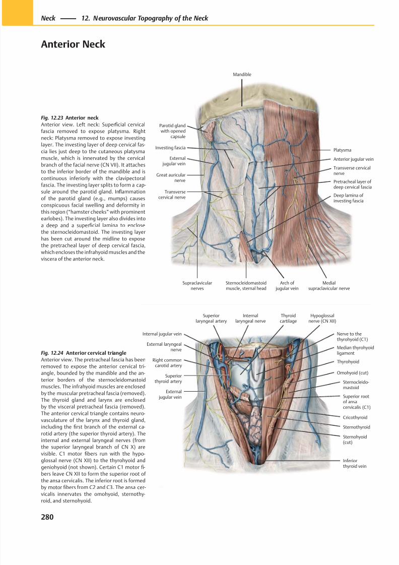
8/15/2019 Head and Neck Anatomy for Dental Medicine - Thieme; (January 26, 2010)
http://slidepdf.com/reader/full/head-and-neck-anatomy-for-dental-medicine-thieme-january-26-2010 293/384
Parotid glandwith opened
capsule
External jugular vein
Great auricularnerve
Transverse
cervical nerve
Supraclavicularnerves
Pretracheal layer ofdeep cervical fascia
Sternocleidomastoidmuscle, sternal head
Arch of jugular vein
Anterior jugular vein
Platysma
Mandible
Investing fascia
Transverse cervicalnerve
Deep lamina of investing fascia
Medialsupraclavicular nerve
Thyroidcartilage
Sternohyoid(cut)
Sternothyroid
Sternocleido-mastoid
Omohyoid (cut)
External
jugular vein
Thyrohyoid
Internal jugular vein
Median thyrohyoidligament
Superiorthyroid artery
Right commoncarotid artery
Superiorlaryngeal artery
External laryngealnerve
Hypoglossalnerve (CN XII)
Internallaryngeal nerve
Nerve to thethyrohyoid (C1)
Cricothyroid
Superior rootof ansacervicalis (C1)
Inferiorthyroid vein
Fig. 12.23 Anterior neck
Anterior view. Left neck: Superficial cervical
fascia removed to expose platysma. Right
neck: Platysma removed to expose investing
layer. The investing layer of deep cervical fas-
cia lies just deep to the cutaneous platysma
muscle, which is innervated by the cervical
branch of the facial nerve (CN VII). It attaches
to the inferior border of the mandible and is
continuous inferiorly with the clavipectoral
fascia. The investing layer splits to form a cap-
sule around the parotid gland. Inflammation
of the parotid gland (e.g., mumps) causesconspicuous facial swelling and deformity in
this region (“hamster cheeks” with prominent
earlobes). The investing layer also divides into
a deep and a superficial lamina to enclose
the sternocleidomastoid. The investing layer
has been cut around the midline to expose
the pretracheal layer of deep cervical fascia,
which encloses the infrahyoid muscles and the
viscera of the anterior neck.
Fig. 12.24 Anterior cervical triangle
Anterior view. The pretracheal fascia has been
removed to expose the anterior cervical tri-
angle, bounded by the mandible and the an-
terior borders of the sternocleidomastoid
muscles. The infrahyoid muscles are enclosed
by the muscular pretracheal fascia (removed).The thyroid gland and larynx are enclosed
by the visceral pretracheal fascia (removed).
The anterior cervical triangle contains neuro-
vasculature of the larynx and thyroid gland,
including the first branch of the external ca-
rotid artery (the superior thyroid artery). The
internal and external laryngeal nerves (from
the superior laryngeal branch of CN X) are
visible. C1 motor fibers run with the hypo-
glossal nerve (CN XII) to the thyrohyoid and
geniohyoid (not shown). Certain C1 motor fi-
bers leave CN XII to form the superior root of
the ansa cervicalis. The inferior root is formed
by motor fibers from C2 and C3. The ansa cer-
vicalis innervates the omohyoid, sternothy-roid, and sternohyoid.
280
Neck 12. Neurovascular Topography of the Neck
Anterior Neck
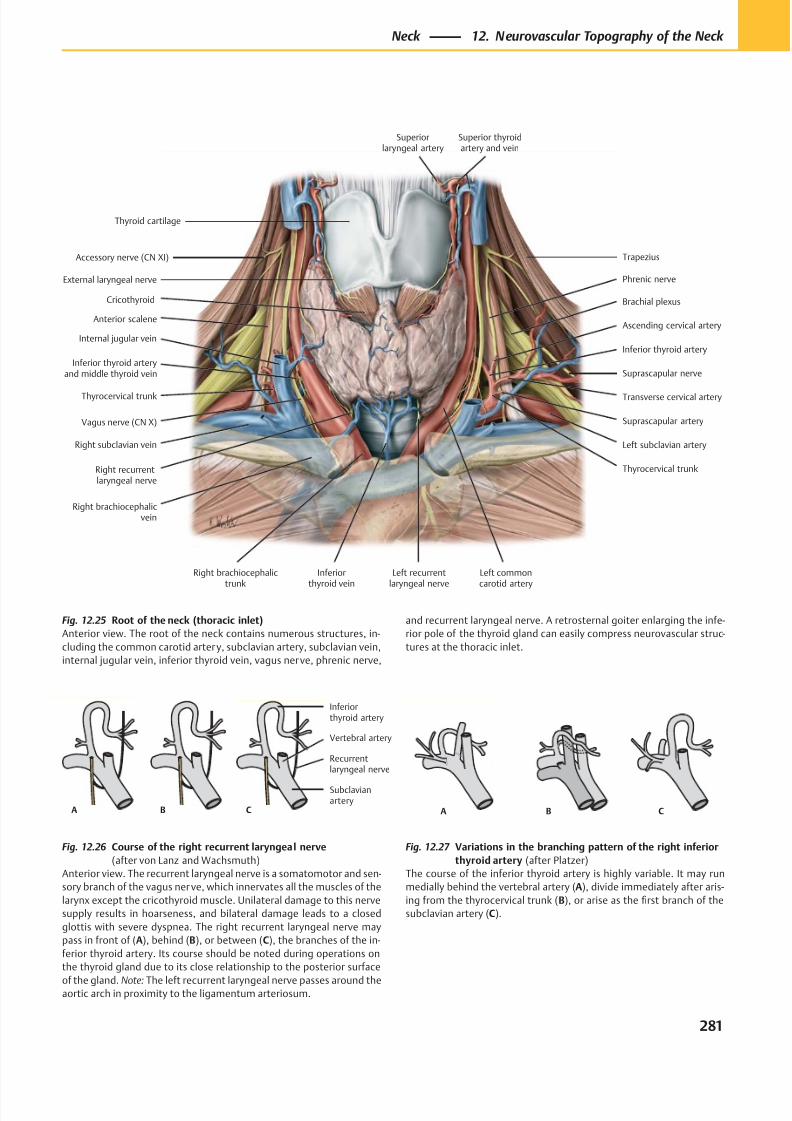
8/15/2019 Head and Neck Anatomy for Dental Medicine - Thieme; (January 26, 2010)
http://slidepdf.com/reader/full/head-and-neck-anatomy-for-dental-medicine-thieme-january-26-2010 294/384
A B C
Inferiorthyroid artery
Vertebral artery
Recurrentlaryngeal nerve
Subclavianartery
A B C
Accessory nerve (CN XI)
Internal jugular vein
Thyrocervical trunk
Right subclavian vein
Left recurrentlaryngeal nerve
Inferiorthyroid vein
Suprascapular nerve
Brachial plexus
Left commoncarotid artery
Trapezius
Phrenic nerve
Cricothyroid
Superior thyroidartery and vein
Thyroid cartilage
Superiorlaryngeal artery
Vagus nerve (CN X)
Inferior thyroid arteryand middle thyroid vein
Left subclavian artery
Thyrocervical trunk
Suprascapular artery
Transverse cervical artery
Inferior thyroid artery
Ascending cervical artery
External laryngeal nerve
Right recurrentlaryngeal nerve
Right brachiocephalicvein
Right brachiocephalictrunk
Anterior scalene
Fig. 12.25 Root of the neck (thoracic inlet)
Anterior view. The root of the neck contains numerous structures, in-
cluding the common carotid artery, subclavian artery, subclavian vein,
internal jugular vein, inferior thyroid vein, vagus nerve, phrenic nerve,
Fig. 12.27 Variations in the branching pattern of the right inferior
thyroid artery (after Platzer)
The course of the inferior thyroid artery is highly variable. It may run
medially behind the vertebral artery (A), divide immediately after aris-
ing from the thyrocervical trunk (B), or arise as the first branch of the
subclavian artery (C).
Fig. 12.26 Course of the right recurrent laryngeal nerve
(after von Lanz and Wachsmuth)
Anterior view. The recurrent laryngeal nerve is a somatomotor and sen-
sory branch of the vagus ner ve, which innervates all the muscles of the
larynx except the cricothyroid muscle. Unilateral damage to this nerve
supply results in hoarseness, and bilateral damage leads to a closed
glottis with severe dyspnea. The right recurrent laryngeal nerve may
pass in front of (A), behind (B), or between (C), the branches of the in-
ferior thyroid artery. Its course should be noted during operations on
the thyroid gland due to its close relationship to the posterior surface
of the gland. Note: The left recurrent laryngeal nerve passes around theaortic arch in proximity to the ligamentum arteriosum.
and recurrent laryngeal nerve. A retrosternal goiter enlarging the infe-
rior pole of the thyroid gland can easily compress neurovascular struc-
tures at the thoracic inlet.
281
Neck 12. Neurovascular Topography of the Neck
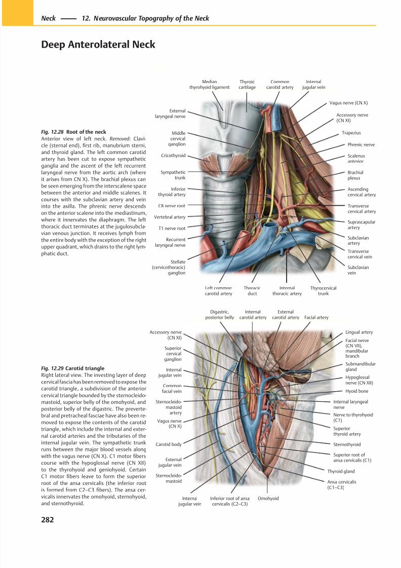
8/15/2019 Head and Neck Anatomy for Dental Medicine - Thieme; (January 26, 2010)
http://slidepdf.com/reader/full/head-and-neck-anatomy-for-dental-medicine-thieme-january-26-2010 295/384
Hypoglossalnerve (CN XII)
Lingual artery
Nerve to thyrohyoid(C1)
Superior root of ansa cervicalis (C1)
Sternothyroid
Thyroid gland
Ansa cervicalis(C1–C3)
Carotid body
External jugular vein
Internal jugular vein
Vagus nerve(CN X)
Sternocleido-mastoid
artery
Internal jugular vein
Externalcarotid artery
Superiorcervical
ganglion
Internalcarotid artery
Digastric,posterior belly
Facial nerve(CN VII),mandibularbranch
Facial artery
Hyoid bone
Internal laryngealnerve
Omohyoid
Sternocleido-mastoid
Accessory nerve(CN XI)
Submandibulargland
Superiorthyroid artery
Commonfacial vein
Inferior root of ansacervicalis (C2–C3)
Recurrentlaryngeal nerve
C8 nerve root
Middlecervical
ganglion
Sympathetictrunk
Scalenusanterior
Inferiorthyroid artery
Transversecervical artery
Internalthoracic artery
Subclavianvein
Suprascapularartery
Thoracicduct
Brachialplexus
Phrenic nerve
Trapezius
Accessory nerve(CN XI)
Internal jugular vein
Commoncarotid artery
Thyroidcartilage
Medianthyrohyoid ligament
Vagus nerve (CN X)
T1 nerve root
Stellate(cervicothoracic)
ganglion
Left commoncarotid artery
Transversecervical vein
Subclavianartery
Externallaryngeal nerve
Cricothyroid
Vertebral artery
Ascendingcervical artery
Thyrocervicaltrunk
Fig. 12.28 Root of the neck
Anterior view of left neck. Removed: Clavi-
cle (sternal end), first rib, manubrium sterni,
and thyroid gland. The left common carotid
artery has been cut to expose sympathetic
ganglia and the ascent of the left recurrent
laryngeal nerve from the aortic arch (where
it arises from CN X). The brachial plexus can
be seen emerging from the interscalene space
between the anterior and middle scalenes. It
courses with the subclavian artery and veininto the axilla. The phrenic nerve descends
on the anterior scalene into the mediastinum,
where it innervates the diaphragm. The left
thoracic duct terminates at the jugulosubcla-
vian venous junction. It receives lymph from
the entire body with the exception of the right
upper quadrant, which drains to the right lym-
phatic duct.
Fig. 12.29 Carotid triangle
Right lateral view. The investing layer of deep
cervical fascia has been removed to expose the
carotid triangle, a subdivision of the anterior
cervical triangle bounded by the sternocleido-mastoid, superior belly of the omohyoid, and
posterior belly of the digastric. The preverte-
bral and pretracheal fasciae have also been re-
moved to expose the contents of the carotid
triangle, which include the internal and exter-
nal carotid arteries and the tributaries of the
internal jugular vein. The sympathetic trunk
runs between the major blood vessels along
with the vagus nerve (CN X). C1 motor fibers
course with the hypoglossal nerve (CN XII)
to the thyrohyoid and geniohyoid. Certain
C1 motor fibers leave to form the superior
root of the ansa cervicalis (the inferior root
is formed from C2–C3 fibers). The ansa cer-
vicalis innervates the omohyoid, sternohyoid,and sternothyroid.
282
Neck 12. Neurovascular Topography of the Neck
Deep Anterolateral Neck
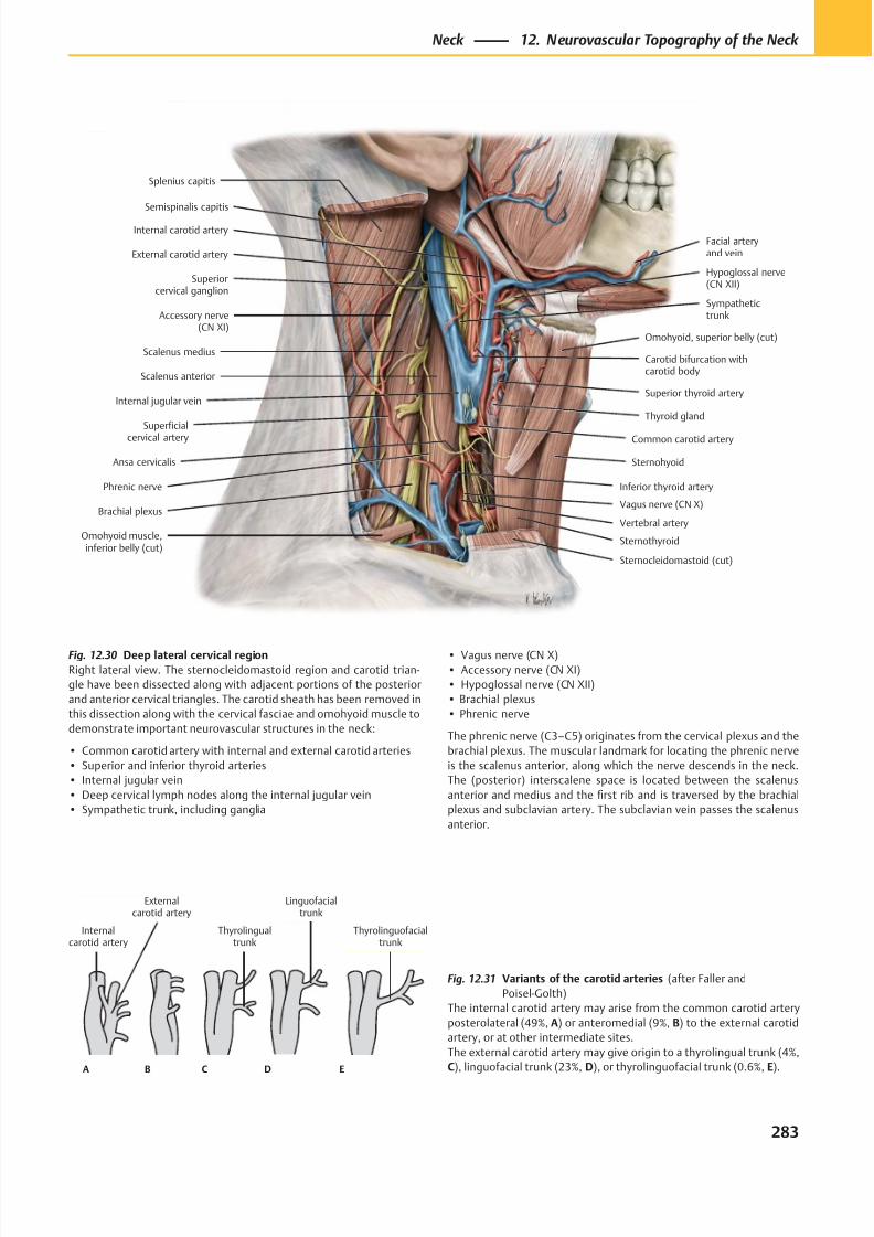
8/15/2019 Head and Neck Anatomy for Dental Medicine - Thieme; (January 26, 2010)
http://slidepdf.com/reader/full/head-and-neck-anatomy-for-dental-medicine-thieme-january-26-2010 296/384
Internalcarotid artery
Thyrolingualtrunk
Externalcarotid artery
Linguofacialtrunk
Thyrolinguofacialtrunk
A B C D E
Superiorcervical ganglion
Internal carotid artery
Scalenus anterior
Scalenus medius
Internal jugular vein
Superficialcervical artery
Phrenic nerve
Ansa cervicalis
Brachial plexus
Omohyoid muscle,inferior belly (cut)
Vagus nerve (CN X)
Sternocleidomastoid (cut)
Sternothyroid
Inferior thyroid artery
Thyroid gland
Common carotid artery
Sternohyoid
Carotid bifurcation withcarotid body
Superior thyroid artery
Omohyoid, superior belly (cut)
External carotid artery
Facial arteryand vein
Hypoglossal nerve(CN XII)
Accessory nerve(CN XI)
Sympathetictrunk
Semispinalis capitis
Splenius capitis
Vertebral artery
Fig. 12.30 Deep lateral cervical region
Right lateral view. The sternocleidomastoid region and carotid trian-
gle have been dissected along with adjacent portions of the posterior
and anterior cervical triangles. The carotid sheath has been removed in
this dissection along with the cervical fasciae and omohyoid muscle to
demonstrate important neurovascular structures in the neck:
• Common carotid artery with internal and external carotid arteries
• Superior and inferior thyroid arteries
• Internal jugular vein
• Deep cervical lymph nodes along the internal jugular vein
• Sympathetic trunk, including ganglia
Fig. 12.31 Variants of the carotid arteries (after Faller and
Poisel-Golth)
The internal carotid artery may arise from the common carotid artery
posterolateral (49%, A) or anteromedial (9%, B) to the external carotid
artery, or at other intermediate sites.
The external carotid artery may give origin to a thyrolingual trunk (4%,
C), linguofacial trunk (23%, D), or thyrolinguofacial trunk (0.6%, E).
• Vagus nerve (CN X)
• Accessory nerve (CN XI)
• Hypoglossal nerve (CN XII)
• Brachial plexus
• Phrenic nerve
The phrenic nerve (C3–C5) originates from the cervical plexus and the
brachial plexus. The muscular landmark for locating the phrenic nerve
is the scalenus anterior, along which the nerve descends in the neck.
The (posterior) interscalene space is located between the scalenus
anterior and medius and the first rib and is traversed by the brachial
plexus and subclavian artery. The subclavian vein passes the scalenus
anterior.
283
Neck 12. Neurovascular Topography of the Neck
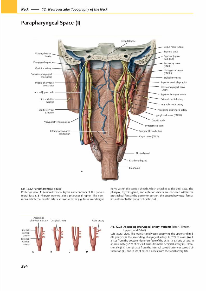
8/15/2019 Head and Neck Anatomy for Dental Medicine - Thieme; (January 26, 2010)
http://slidepdf.com/reader/full/head-and-neck-anatomy-for-dental-medicine-thieme-january-26-2010 297/384
Pharyngobasilarfascia
Occipital artery
Superior pharyngealconstrictor
Middle pharyngealconstrictor
Thyroid gland
Carotid body
Internal carotid artery
Superior laryngeal nerve
Glossopharyngeal nerve(CN IX)
Sternocleido-
mastoid
Hypoglossal nerve(CN XII)
Accessory nerve(CN XI)
Superior cervical ganglion
Sigmoid sinus
Hypoglossal nerve (CN XII)
Internal jugular vein
Pharyngeal venous plexus
Pharyngeal raphe
Stylopharyngeus
External carotid artery
Ascending pharyngeal artery
Sympathetic trunk
Superior thyroid artery
Vagus nerve (CN X)
Inferior pharyngealconstrictor
Middle cervicalganglion
A
Parathyroid gland
Esophagus
Superior jugularbulb (cut)
Vagus nerve (CN X)
Occipital bone
DA
Internalcarotidartery
Ascendingpharyngeal artery Facial artery
Externalcarotidartery
Occipital artery
B C
Fig. 12.32 Parapharyngeal space
Posterior view. A Removed: Fascial layers and contents of the prever-
tebral fascia. B Pharynx opened along pharyngeal raphe. The com-
mon and internal carotid arteries travel with the jugular vein and vagus
Fig. 12.33 Ascending pharyngeal artery: variants (after Tillmann,
Lippert, and Pabst)
Left lateral view. The main arterial vessel supplying the upper and mid-
dle pharynx is the ascending pharyngeal artery. In 70% of cases (A) it
arises from the posteroinferior surface of the external carotid artery. In
approximately 20% of cases it arises from the occipital artery (B). Occa-
sionally (8%) it originates from the internal carotid artery or carotid bi-
furcation (C), and in 2% of cases it arises from the facial artery (D).
nerve within the carotid sheath, which attaches to the skull base. The
pharynx, thyroid gland, and anterior viscera are enclosed within the
pretracheal fascia (the posterior portion, the buccopharyngeal fascia,
lies anterior to the prevertebral fascia).
284
Neck 12. Neurovascular Topography of the Neck
Parapharyngeal Space (I)
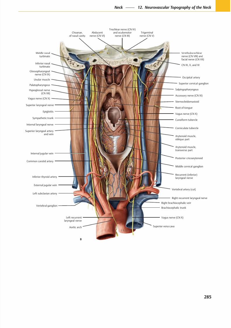
8/15/2019 Head and Neck Anatomy for Dental Medicine - Thieme; (January 26, 2010)
http://slidepdf.com/reader/full/head-and-neck-anatomy-for-dental-medicine-thieme-january-26-2010 298/384
Inferior nasalturbinate
Middle nasal
turbinate
Glossopharyngealnerve (CN IX)
Uvular muscle
Palatopharyngeus
Hypoglossal nerve(CN XII)
Superior laryngeal nerve
Sympathetic trunk
Internal laryngeal nerve
Superior laryngeal arteryand vein
Cuneiform tubercle
Corniculate tubercle
Epiglottis
Right recurrent laryngeal nerve
External jugular vein
Inferior thyroid artery
Common carotid artery
Middle cervical ganglion
Internal jugular vein
Arytenoid muscle,transverse part
Arytenoid muscle,oblique part
Vagus nerve (CN X)
Sternocleidomastoid
Accessory nerve (CN XI)
Occipital artery
Salpingopharyngeus
CN IX, X, and XI
Vestibulocochlear
nerve (CN VIII) andfacial nerve (CN VII)
Trigeminalnerve (CN V)
Abducentnerve (CN VI)
Trochlear nerve (CN IV)and oculomotor
nerve (CN III)
Vagus nerve (CN X)
Left subclavian artery
Brachiocephalic trunk
Vagus nerve (CN X)
Recurrent (inferior)laryngeal nerve
Posterior cricoarytenoid
Superior cervical ganglion
Choanae,of nasal cavity
Left recurrentlaryngeal nerve
Vertebral ganglion
Aortic arch
B
Superior vena cava
Right brachiocephalic vein
Vertebral artery (cut)
Root of tongue
285
Neck 12. Neurovascular Topography of the Neck
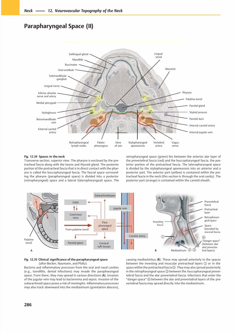
8/15/2019 Head and Neck Anatomy for Dental Medicine - Thieme; (January 26, 2010)
http://slidepdf.com/reader/full/head-and-neck-anatomy-for-dental-medicine-thieme-january-26-2010 299/384
Inferior alveolarnerve and artery
Medial pterygoid
Styloglossus
Retromandibularvein
External carotidartery
Retropharyngeallymph nodes
Palato-pharyngeus
Vertebralartery
Densof axis
Internal carotid artery
Vagusnerve
Internal jugular vein
Parotid gland
Styloid process
Lingual nerve
Submandibularganglion
Oral vestibule
Mandible
Palatine tonsil
Pharynx
Sublingual gland
Masseter
Lingual
tonsil
Parotid duct
Stylopharyngealaponeurosis
Buccinator
A
Palatinetonsil
From palatine tonsil
Subarachnoid space
Cavernoussinus
Orbit
Jugular vein
Carotid artery
Parotid gland Cervicalsoft tissues
Para-pharyngeal
space
B
Prevertebralfascia
Spacebounded by
visceral fascia④ “Danger space”(between alarand preverte-bral layers)Mediastinum
Pretracheallayer
Investingfascia
①
②
Retropharyn-geal space
③
Fig. 12.34 Spaces in the neck
Transverse section, superior view. The pharynx is enclosed by the pre-
tracheal fascia along with the larynx and thyroid gland. The posterior
portion of the pretracheal fascia that is in direct contact with the phar-
ynx is called the buccopharyngeal fascia. The fascial space surround-
ing the pharynx (parapharyngeal space) is divided into a posterior
(retropharyngeal) space and a lateral (lateropharyngeal) space. The
Fig. 12.35 Clinical significance of the parapharyngeal space
(after Becker, Naumann, and Pfaltz)
Bacteria and inflammatory processes from the oral and nasal cavities
(e.g., tonsillitis, dental infections) may invade the parapharyngeal
space. From there, they may spread in various directions (A). Invasion
of the jugular vein may lead to bacteremia and sepsis. Invasion of the
subarachnoid space poses a risk of meningitis. Inflammatory processes
may also track downward into the mediastinum (gravitation abscess),
retropharyngeal space (green) lies between the anterior alar layer of
the prevertebral fascia (red) and the buccopharyngeal fascia, the pos-
terior portion of the pretracheal fascia. The lateropharyngeal space
is divided by the stylopharyngeal aponeurosis into an anterior and a
posterior part. The anterior part (yellow) is contained within the pre-
tracheal fascia in the neck (this section is through the oral cavity). The
posterior part (orange) is contained within the carotid sheath.
causing mediastinitus (B). These may spread anteriorly in the spaces
between the investing and muscular pretracheal layers ① or in the
space within the pretracheal fascia②. They may also spread posteriorly
in the retropharyngeal space ③ between the buccopharyngeal prever-
tebral fascia and the alar prevertebral fascia. Infections that enter the
“danger space” ④ between the alar and prevertebral layers of the pre-
vertebral fascia may spread directly into the mediastinum.
286
Neck 12. Neurovascular Topography of the Neck
Parapharyngeal Space (II)
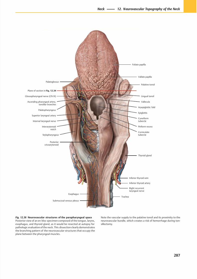
8/15/2019 Head and Neck Anatomy for Dental Medicine - Thieme; (January 26, 2010)
http://slidepdf.com/reader/full/head-and-neck-anatomy-for-dental-medicine-thieme-january-26-2010 300/384
Inferior thyroid vein
Inferior thyroid artery
Right recurrentlaryngeal nerve
Esophagus
Submucosal venous plexus
Corniculatetubercle
Piriform recess
Cuneiformtubercle
Aryepiglottic fold
Palatine tonsil
Vallate papilla
Foliate papilla
Trachea
Internal laryngeal nerve
Superior laryngeal arteryEpiglottis
Plane of section in Fig. 12.34
Thyroid gland
Posteriorcricoarytenoid
Interarytenoidnotch
Stylopharyngeus
Palatopharyngeus
Glossopharyngeal nerve (CN IX)
Ascending pharyngeal artery,tonsillar branches
Palatoglossus
Lingual tonsil
Vallecula
Fig. 12.36 Neurovascular structures of the parapharyngeal space
Posterior view of an en bloc specimen composed of the tongue, larynx,
esophagus, and thyroid gland, as it would be resected at autopsy for
pathologic evaluation of the neck. This dissection clearly demonstrates
the branching pattern of the neurovascular structures that occupy the
plane between the pharyngeal muscles.
Note the vascular supply to the palatine tonsil and its proximity to the
neurovascular bundle, which creates a risk of hemorrhage during ton-
sillectomy.
287
Neck 12. Neurovascular Topography of the Neck
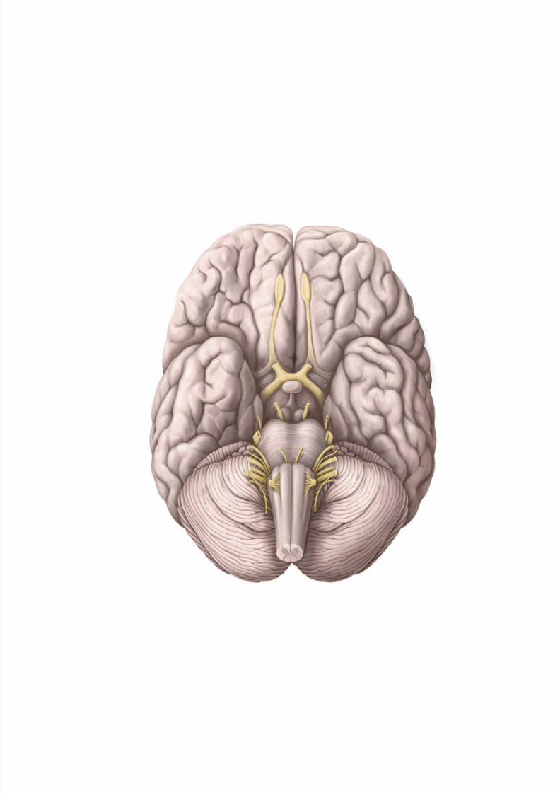
8/15/2019 Head and Neck Anatomy for Dental Medicine - Thieme; (January 26, 2010)
http://slidepdf.com/reader/full/head-and-neck-anatomy-for-dental-medicine-thieme-january-26-2010 301/384
8/15/2019 Head and Neck Anatomy for Dental Medicine - Thieme; (January 26, 2010)
http://slidepdf.com/reader/full/head-and-neck-anatomy-for-dental-medicine-thieme-january-26-2010 302/384
Neuroanatomy
13 Neuroanatomy
Nervous System . . . . . . . . . . . . . . . . . . . . . . . . . . . . . . . . . . . . 290
Spinal Cord: Organization . . . . . . . . . . . . . . . . . . . . . . . . . . . . 292
Brain: Organization . . . . . . . . . . . . . . . . . . . . . . . . . . . . . . . . . 294
Brain & Meninges . . . . . . . . . . . . . . . . . . . . . . . . . . . . . . . . . . . 296
Spinal Cord & Meninges . . . . . . . . . . . . . . . . . . . . . . . . . . . . . 298
Cerebrospinal Fluid (CSF) Spaces . . . . . . . . . . . . . . . . . . . . . . 300
Dural Sinuses . . . . . . . . . . . . . . . . . . . . . . . . . . . . . . . . . . . . . . 302
Arteries of the Brain . . . . . . . . . . . . . . . . . . . . . . . . . . . . . . . . 304Neurons . . . . . . . . . . . . . . . . . . . . . . . . . . . . . . . . . . . . . . . . . . 306
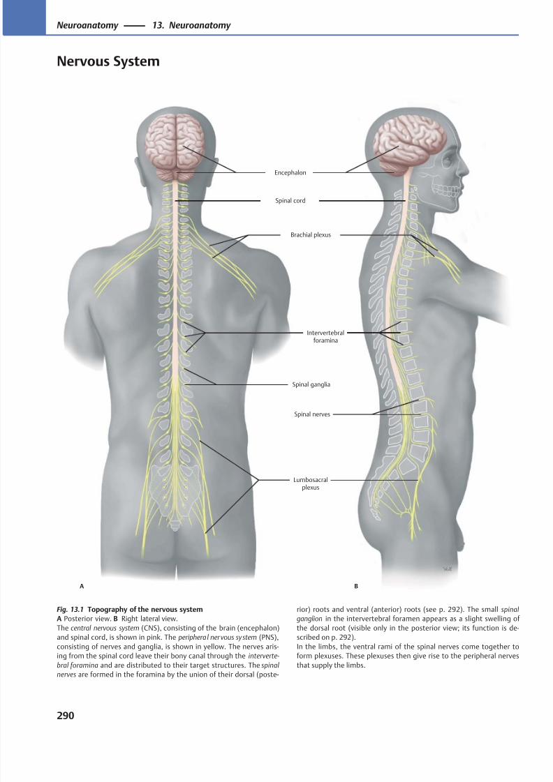
8/15/2019 Head and Neck Anatomy for Dental Medicine - Thieme; (January 26, 2010)
http://slidepdf.com/reader/full/head-and-neck-anatomy-for-dental-medicine-thieme-january-26-2010 303/384
A B
Lumbosacralplexus
Brachial plexus
Spinal ganglia
Intervertebralforamina
Spinal cord
Encephalon
Spinal nerves
Fig. 13.1 Topography of the nervous system
A Posterior view. B Right lateral view.
The central nervous system (CNS), consisting of the brain (encephalon)
and spinal cord, is shown in pink. The peripheral ner vous system (PNS),
consisting of nerves and ganglia, is shown in yellow. The nerves aris-
ing from the spinal cord leave their bony canal through the interverte-
bral foramina and are distributed to their target structures. The spinal
nerves are formed in the foramina by the union of their dorsal (poste-
rior) roots and ventral (anterior) roots (see p. 292). The small spinal
ganglion in the intervertebral foramen appears as a slight swelling of
the dorsal root (visible only in the posterior view; its function is de-
scribed on p. 292).
In the limbs, the ventral rami of the spinal nerves come together to
form plexuses. These plexuses then give rise to the peripheral nerves
that supply the limbs.
290
Neuroanatomy 13. Neuroanatomy
Nervous System
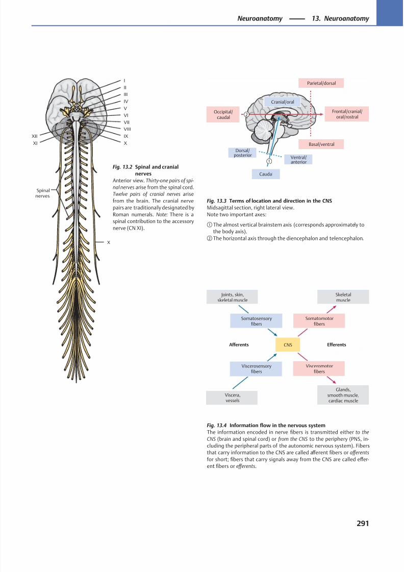
8/15/2019 Head and Neck Anatomy for Dental Medicine - Thieme; (January 26, 2010)
http://slidepdf.com/reader/full/head-and-neck-anatomy-for-dental-medicine-thieme-january-26-2010 304/384
①
②
Cranial/oral
Parietal/dorsal
Frontal/cranial/oral/rostral
Basal/ventral
Ventral/anterior
Caudal
Dorsal/posterior
Occipital/caudal
EfferentsAfferents
Visceromotorfibers
Viscerosensoryfibers
Viscera,
vessels
Joints, skin,
skeletal muscle
Somatosensoryfibers
Somatomotorfibers
Skeletal
muscle
CNS
Glands,smooth muscle,
cardiac muscle
XII
XI X
IX
VIII
VII
VI
V
IV
III
II
I
X
Spinalnerves
Fig. 13.4 Information flow in the nervous system
The information encoded in nerve fibers is transmitted either to the
CNS (brain and spinal cord) or from the CNS to the periphery (PNS, in-
cluding the peripheral parts of the autonomic nervous system). Fibers
that carry information to the CNS are called aff erent fibers or aff erents
for short; fibers that carry signals away from the CNS are called eff er-
ent fibers or eff erents.
Fig. 13.2 Spinal and cranial
nerves
Anterior view. Thirty-one pairs of spi-
nal nerves arise from the spinal cord.
Twelve pairs of cranial nerves arise
from the brain. The cranial nervepairs are traditionally designated by
Roman numerals. Note: There is a
spinal contribution to the accessory
nerve (CN XI).
Fig. 13.3 Terms of location and direction in the CNSMidsagittal section, right lateral view.
Note two important axes:
① The almost vertical brainstem axis (corresponds approximately to
the body axis).
② The horizontal axis through the diencephalon and telencephalon.
291
Neuroanatomy 13. Neuroanatomy
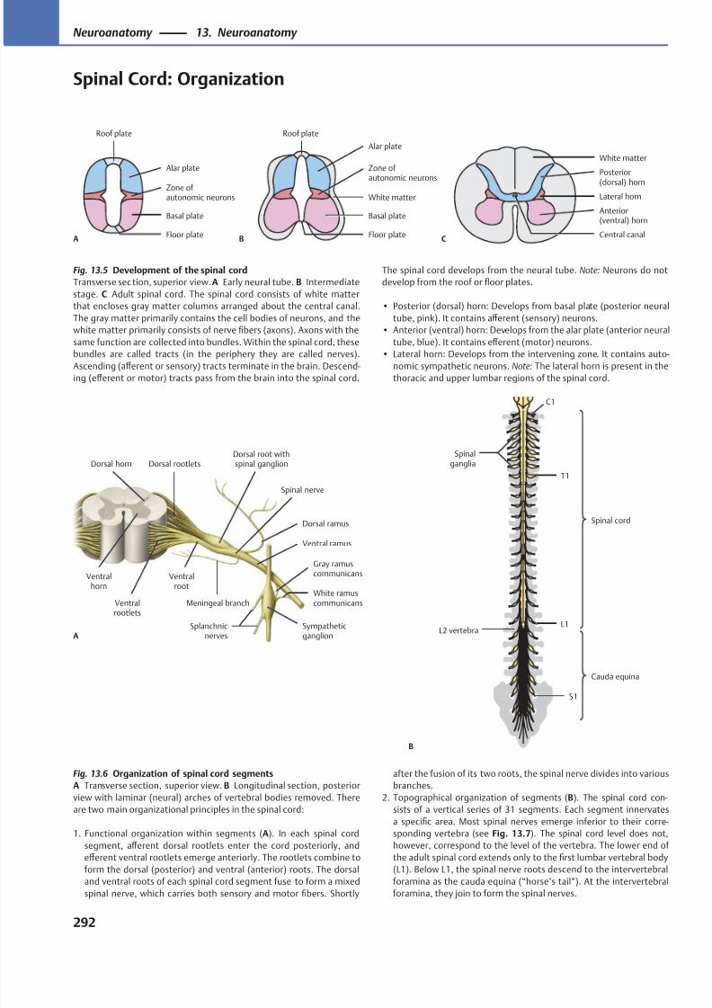
8/15/2019 Head and Neck Anatomy for Dental Medicine - Thieme; (January 26, 2010)
http://slidepdf.com/reader/full/head-and-neck-anatomy-for-dental-medicine-thieme-january-26-2010 305/384
Roof plate
AFloor plate
Basal plate
Zone ofautonomic neurons
Alar plate
Floor plate
White matter
Basal plate
Zone of
autonomic neurons
Alar plate
Roof plate
BCentral canal
White matter
Anterior(ventral) horn
Lateral horn
Posterior(dorsal) horn
C
Spinal cord
Cauda equina
Spinalganglia
L2 vertebra
S1
L1
T1
C1
B
Ventralrootlets
Meningeal branch
Ventral ramus
Splanchnicnerves
Sympatheticganglion
White ramuscommunicans
Gray ramuscommunicans
Dorsal ramus
Dorsal root withspinal ganglionDorsal rootlets
Ventralroot
Spinal nerve
A
Dorsal horn
Ventralhorn
Fig. 13.5 Development of the spinal cord
Transverse sec tion, superior view. A Early neural tube. B Intermediate
stage. C Adult spinal cord. The spinal cord consists of white matter
that encloses gray matter columns arranged about the central canal.
The gray matter primarily contains the cell bodies of neurons, and the
white matter primarily consists of nerve fibers (axons). Axons with the
same function are collected into bundles. Within the spinal cord, these
bundles are called tracts (in the periphery they are called nerves).Ascending (aff erent or sensory) tracts terminate in the brain. Descend-
ing (eff erent or motor) tracts pass from the brain into the spinal cord.
Fig. 13.6 Organization of spinal cord segments
A Transverse section, superior view. B Longitudinal section, posterior
view with laminar (neural) arches of vertebral bodies removed. There
are two main organizational principles in the spinal cord:
1. Functional organization within segments (A). In each spinal cord
segment, aff erent dorsal rootlets enter the cord posteriorly, and
eff erent ventral rootlets emerge anteriorly. The rootlets combine to
form the dorsal (posterior) and ventral (anterior) roots. The dorsal
and ventral roots of each spinal cord segment fuse to form a mixedspinal nerve, which carries both sensory and motor fibers. Shortly
after the fusion of its two roots, the spinal nerve divides into various
branches.
2. Topographical organization of segments (B). The spinal cord con-
sists of a vertical series of 31 segments. Each segment innervates
a specific area. Most spinal nerves emerge inferior to their corre-
sponding vertebra (see Fig. 13.7). The spinal cord level does not,
however, correspond to the level of the vertebra. The lower end of
the adult spinal cord extends only to the first lumbar vertebral body
(L1). Below L1, the spinal nerve roots descend to the intervertebral
foramina as the cauda equina (“horse’s tail”). At the intervertebralforamina, they join to form the spinal nerves.
The spinal cord develops from the neural tube. Note: Neurons do not
develop from the roof or floor plates.
• Posterior (dorsal) horn: Develops from basal plate (posterior neural
tube, pink). It contains aff erent (sensory) neurons.
• Anterior (ventral) horn: Develops from the alar plate (anterior neural
tube, blue). It contains eff erent (motor) neurons.
• Lateral horn: Develops from the intervening zone. It contains auto-nomic sympathetic neurons. Note: The lateral horn is present in the
thoracic and upper lumbar regions of the spinal cord.
292
Neuroanatomy 13. Neuroanatomy
Spinal Cord: Organization
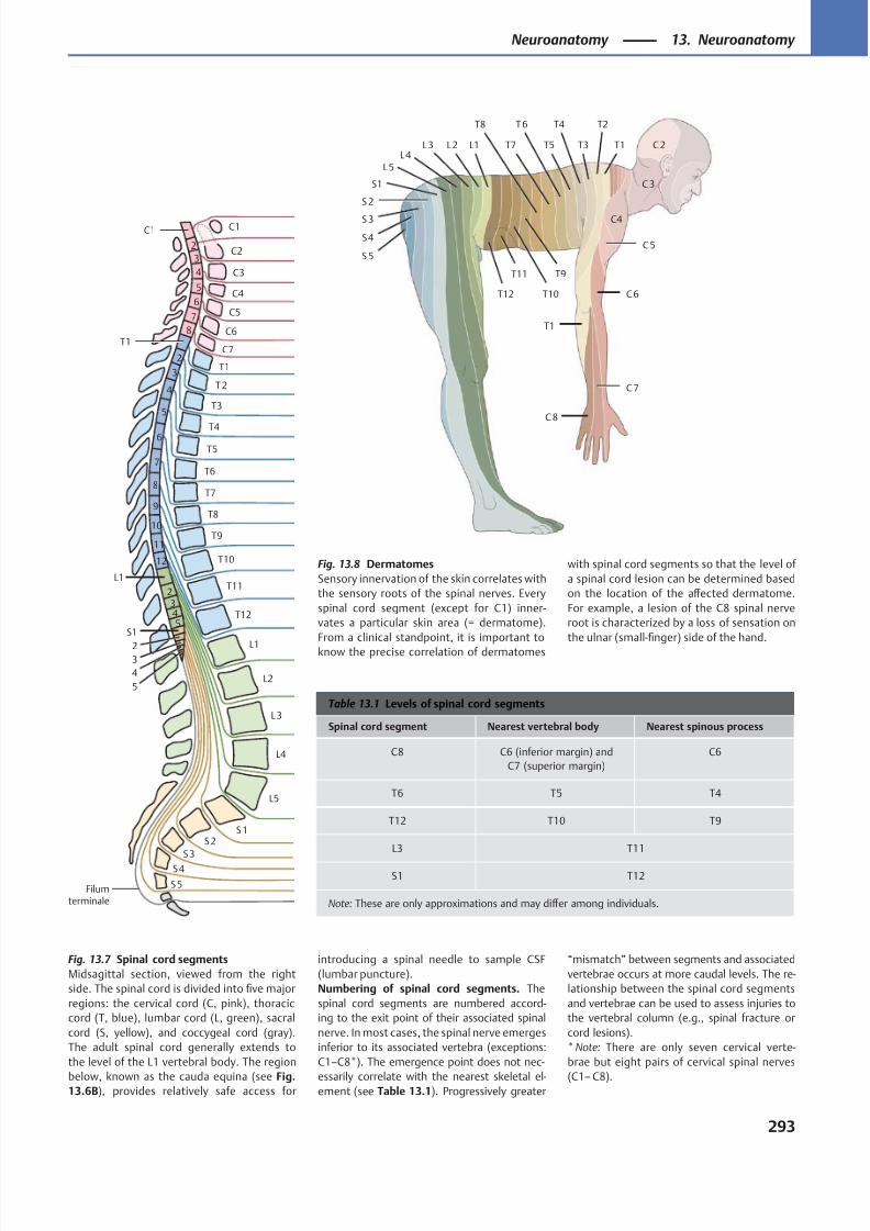
8/15/2019 Head and Neck Anatomy for Dental Medicine - Thieme; (January 26, 2010)
http://slidepdf.com/reader/full/head-and-neck-anatomy-for-dental-medicine-thieme-january-26-2010 306/384
C7
C6
C5
C4
C3
C2
C1
T11
T10
T9
T8
T7
T6
T5
T4
T3
T2
T1
S5
S4
S3
S2S1
L5
L4
L3
L2
L1
6
5
4
3
2
C1
T1
7
6
5
4
3
2
8
9
10
11
12
L1
543
2
S1
5
4
32
T12
7
8
Filumterminale
T12
T11
T10
T9
T8
T7
T6
T5
T4
T3
T2
T1
T1L1L2L3L4
L5
S1
S 2
S 3
S4
S 5
C 2
C 3
C4
C 5
C 7
C 8
C 6
Table 13.1 Levels of spinal cord segments
Spinal cord segment Nearest vertebral body Nearest spinous process
C8 C6 (inferior margin) and
C7 (superior margin)
C6
T6 T5 T4
T12 T10 T9
L3 T11
S1 T12
Note: These are only approximations and may diff er among individuals.
Fig. 13.8 Dermatomes
Sensory innervation of the skin correlates with
the sensory roots of the spinal nerves. Every
spinal cord segment (except for C1) inner-
vates a particular skin area (= dermatome).
From a clinical standpoint, it is important to
know the precise correlation of dermatomes
with spinal cord segments so that the level of
a spinal cord lesion can be determined based
on the location of the aff ected dermatome.
For example, a lesion of the C8 spinal nerve
root is characterized by a loss of sensation on
the ulnar (small-finger) side of the hand.
Fig. 13.7 Spinal cord segments
Midsagittal section, viewed from the right
side. The spinal cord is divided into five major
regions: the cervical cord (C, pink), thoracic
cord (T, blue), lumbar cord (L, green), sacral
cord (S, yellow), and coccygeal cord (gray).
The adult spinal cord generally extends to
the level of the L1 vertebral body. The region
below, known as the cauda equina (see Fig.13.6B), provides relatively safe access for
introducing a spinal needle to sample CSF
(lumbar puncture).
Numbering of spinal cord segments. The
spinal cord segments are numbered accord-
ing to the exit point of their associated spinal
nerve. In most cases, the spinal nerve emerges
inferior to its associated vertebra (exceptions:
C1–C8*). The emergence point does not nec-
essarily correlate with the nearest skeletal el-ement (see Table 13.1). Progressively greater
“mismatch” between segments and associated
vertebrae occurs at more caudal levels. The re-
lationship between the spinal cord segments
and vertebrae can be used to assess injuries to
the vertebral column (e.g., spinal fracture or
cord lesions).
* Note: There are only seven cervical verte-
brae but eight pairs of cervical spinal nerves
(C1– C8).
293
Neuroanatomy 13. Neuroanatomy
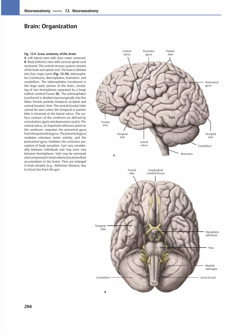
8/15/2019 Head and Neck Anatomy for Dental Medicine - Thieme; (January 26, 2010)
http://slidepdf.com/reader/full/head-and-neck-anatomy-for-dental-medicine-thieme-january-26-2010 307/384
Precentralgyrus
Centralsulcus
Parietallobe
Postcentralgyrus
Occipitallobe
Lateralsulcus
Temporallobe
Frontallobe
Cerebellum
BrainstemA
Frontallobe
Longitudinalcerebral fissure
Medullaoblongata
Cerebellum Cervical cord
Pons
Temporallobe
Hypophysis
(pituitary)
B
Fig. 13.9 Gross anatomy of the brain
A Left lateral view with dura mater removed.B Basal (inferior) view with cervical spinal cord
sectioned. The central nervous system consists
of the brain and spinal cord. The brain is divided
into four major parts (Fig. 13.10): telencepha-
lon (cerebrum), diencephalon, brainstem, and
cerebellum. The telencephalon (cerebrum) is
the large outer portion of the brain, consist-
ing of two hemispheres separated by a longi-
tudinal cerebral fissure (B). The telencephalon
(cerebrum) is divided macroscopically into five
lobes: frontal, parietal, temporal, occipital, and
central (insular). Note: The central (insular) lobe
cannot be seen unless the temporal or parietal
lobe is retracted at the lateral sulcus. The sur-
face contours of the cerebrum are defined byconvolutions (gyri) and depressions (sulci). The
central sulcus, an important reference point on
the cerebrum, separates the precentral gyrus
from the postcentral gyrus. The precentral gyrus
mediates voluntary motor activity, and the
postcentral gyrus mediates the conscious per-
ception of body sensation. Gyri vary consider-
ably between individuals and may even vary
between hemispheres. Sulci may be narrowed
and compressed in brain edema (excessive fluid
accumulation in the brain). They are enlarged
in brain atrophy (e.g., Alzheimer disease), due
to tissue loss from the gyri.
294
Neuroanatomy 13. Neuroanatomy
Brain: Organization
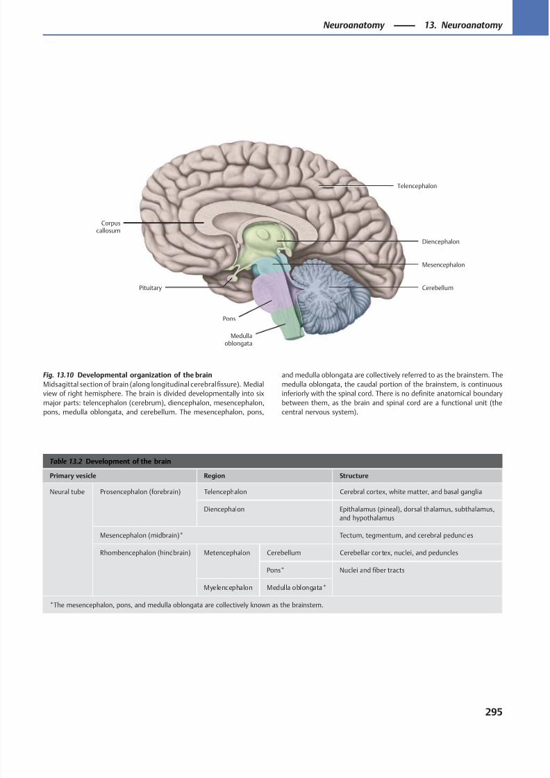
8/15/2019 Head and Neck Anatomy for Dental Medicine - Thieme; (January 26, 2010)
http://slidepdf.com/reader/full/head-and-neck-anatomy-for-dental-medicine-thieme-january-26-2010 308/384
Telencephalon
Diencephalon
Pons
Cerebellum
Medullaoblongata
Corpuscallosum
Mesencephalon
Pituitary
Table 13.2 Development of the brain
Primary vesicle Region Structure
Neural tube Prosencephalon (forebrain) Telencephalon Cerebral cortex, white matter, and basal ganglia
Diencephalon Epithalamus (pineal), dorsal thalamus, subthalamus,
and hypothalamus
Mesencephalon (midbrain)* Tectum, tegmentum, and cerebral peduncles
Rhombencephalon (hindbrain) Metencephalon Cerebellum Cerebellar cor tex, nuclei, and peduncles
Pons* Nuclei and fiber tracts
Myelencephalon Medulla oblongata*
*The mesencephalon, pons, and medulla oblongata are collectively known as the brainstem.
Fig. 13.10 Developmental organization of the brain
Midsagittal section of brain (along longitudinal cerebral fissure). Medial
view of right hemisphere. The brain is divided developmentally into six
major parts: telencephalon (cerebrum), diencephalon, mesencephalon,
pons, medulla oblongata, and cerebellum. The mesencephalon, pons,
and medulla oblongata are collectively referred to as the brainstem. The
medulla oblongata, the caudal portion of the brainstem, is continuous
inferiorly with the spinal cord. There is no definite anatomical boundary
between them, as the brain and spinal cord are a functional unit (the
central nervous system).
295
Neuroanatomy 13. Neuroanatomy
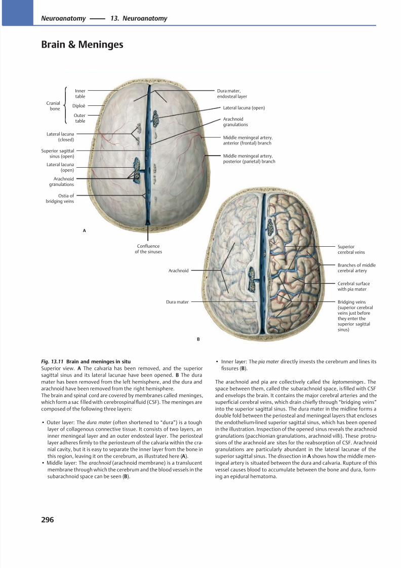
8/15/2019 Head and Neck Anatomy for Dental Medicine - Thieme; (January 26, 2010)
http://slidepdf.com/reader/full/head-and-neck-anatomy-for-dental-medicine-thieme-january-26-2010 309/384
Arachnoid
Dura mater
Cerebral surfacewith pia mater
Branches of middlecerebral artery
Superiorcerebral veins
B
Bridging veins(superior cerebralveins just beforethey enter thesuperior sagittalsinus)
Outertable
Diploë
Innertable
Cranialbone
Lateral lacuna(closed)
Superior sagittalsinus (open)
Lateral lacuna(open)
Arachnoidgranulations
Confluenceof the sinuses
Ostia of bridging veins
Middle meningeal artery,posterior (parietal) branch
Middle meningeal artery,anterior (frontal) branch
Arachnoidgranulations
Lateral lacuna (open)
Dura mater,endosteal layer
A
Fig. 13.11 Brain and meninges in situ
Superior view. A The calvaria has been removed, and the superior
sagittal sinus and its lateral lacunae have been opened. B The dura
mater has been removed from the left hemisphere, and the dura and
arachnoid have been removed from the right hemisphere.
The brain and spinal cord are covered by membranes called meninges,which form a sac filled with cerebrospinalfluid (CSF). The meninges are
composed of the following three layers:
• Outer layer: The dura mater (often shortened to “dura”) is a tough
layer of collagenous connective tissue. It consists of two layers, an
inner meningeal layer and an outer endosteal layer. The periosteal
layer adheres firmly to the periosteum of the calvaria within the cra-
nial cavity, but it is easy to separate the inner layer from the bone in
this region, leaving it on the cerebrum, as illustrated here (A).
• Middle layer: The arachnoid (arachnoid membrane) is a translucent
membrane through which the cerebrum and the blood vessels in the
subarachnoid space can be seen (B).
• Inner layer: The pia mater directly invests the cerebrum and lines its
fissures (B).
The arachnoid and pia are collectively called the leptomeninges . The
space between them, called the subarachnoid space, is filled with CSF
and envelops the brain. It contains the major cerebral arteries and thesuperficial cerebral veins, which drain chiefly through “bridging veins”
into the superior sagittal sinus. The dura mater in the midline forms a
double fold between the periosteal and meningeal layers that encloses
the endothelium-lined superior sagittal sinus, which has been opened
in the illustration. Inspection of the opened sinus reveals the arachnoid
granulations (pacchionian granulations, arachnoid villi). These protru-
sions of the arachnoid are sites for the reabsorption of CSF. Arachnoid
granulations are particularly abundant in the lateral lacunae of the
superior sagittal sinus. The dissection in A shows how the middle men-
ingeal artery is situated between the dura and calvaria. Rupture of this
vessel causes blood to accumulate between the bone and dura, form-
ing an epidural hematoma.
296
Neuroanatomy 13. Neuroanatomy
Brain & Meninges
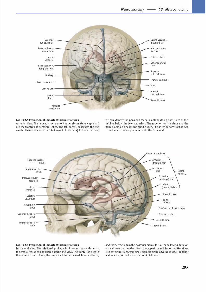
8/15/2019 Head and Neck Anatomy for Dental Medicine - Thieme; (January 26, 2010)
http://slidepdf.com/reader/full/head-and-neck-anatomy-for-dental-medicine-thieme-january-26-2010 310/384
Telencephalon,
frontal lobe
Lateralventricle
Telencephalon,temporal lobe
Interventricular
foramen
Third ventricle
Cerebellum
Medullaoblongata
Cavernous sinus
Basilarplexus
Inferiorpetrosal sinus
Sigmoid sinus
Transverse sinus
Sphenoparietalsinus
Superiorpetrosal sinusPituitary
Lateral ventricle,anterior horn
Superiorsagittal sinus
Pons
Superior sagittalsinus
Inferior sagittalsinus
Interventricularforamen
Thirdventricle
Cerebralaqueduct Fourth
ventricleCavernous
sinus
Inferior petrosalsinus
Superior petrosalsinus
Great cerebral vein
Sigmoid sinus
Occipital sinus
Transverse sinus
Confluence of the sinuses
Straight sinus
Inferior(temporal) horn
Posterior(occipital) horn
Centralpart
Anterior(frontal) horn
Lateralventricle
Fig. 13.13 Projection of important brain structures
Left lateral view. The relationship of specific lobes of the cerebrum to
the cranial fossae can be appreciated in this view. The frontal lobe lies in
the anterior cranial fossa, the temporal lobe in the middle cranial fossa,
Fig. 13.12 Projection of important brain structures
Anterior view. The largest structures of the cerebrum (telencephalon)
are the frontal and temporal lobes. The falx cerebri separates the two
cerebral hemispheres in the midline (not visible here). In the brainstem,
and the cerebellum in the posterior cranial fossa. The following dural ve-
nous sinuses can be identified: the superior and inferior sagittal sinus,
straight sinus, transverse sinus, sigmoid sinus, cavernous sinus, superior
and inferior petrosal sinus, and occipital sinus.
we can identify the pons and medulla oblongata on both sides of the
midline below the telencephalon. The superior sagittal sinus and the
paired sigmoid sinuses can also be seen. The anterior horns of the two
lateral ventricles are projected onto the forehead.
297
Neuroanatomy 13. Neuroanatomy
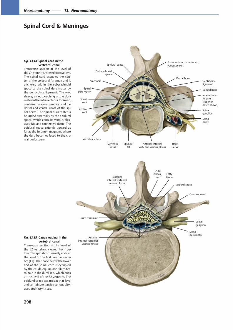
8/15/2019 Head and Neck Anatomy for Dental Medicine - Thieme; (January 26, 2010)
http://slidepdf.com/reader/full/head-and-neck-anatomy-for-dental-medicine-thieme-january-26-2010 311/384
Spinalganglion
Anterior internalvertebral venous plexus
Dorsalroot
Vertebralveins
Intervertebralforamen(superiornotch shown)
Spinalnerve
Vertebral artery
Ventralroot
Posterior internal vertebralvenous plexus
Denticulateligament
Epidural space
Subarachnoidspace
Spinaldura mater
Arachnoid
Rootsleeve
Ventral horn
Dorsal horn
Epiduralfat
Anteriorinternal vertebral
venous plexus
Spinalganglion
Spinaldura mater
Fattytissue
Cauda equina
Epidural space
Posteriorinternal vertebral
venous plexus
Dural
(thecal)sac
Filum terminale
Fig. 13.15 Cauda equina in the
vertebral canal
Transverse section at the level of
the L2 vertebra, viewed from be-
low. The spinal cord usually ends at
the level of the first lumbar verte-
bra (L1). The space below the lower
end of the spinal cord is occupied
by the cauda equina and filum ter-
minale in the dural sac, which ends
at the level of the S2 vertebra. The
epidural space expands at that level
and contains extensive venous plex-
uses and fatty tissue.
Fig. 13.14 Spinal cord in the
vertebral canal
Transverse section at the level of
the C4 vertebra, viewed from above.
The spinal cord occupies the cen-
ter of the vertebral foramen and is
anchored within the subarachnoid
space to the spinal dura mater by
the denticulate ligament. The root
sleeve, an outpouching of the dura
mater in the intravertebral foramen,
contains the spinal ganglion and the
dorsal and ventral roots of the spi-
nal nerve. The spinal dura mater is
bounded externally by the epiduralspace, which contains venous plex-
uses, fat, and connective tissue. The
epidural space extends upward as
far as the foramen magnum, where
the dura becomes fused to the cra-
nial periosteum.
298
Neuroanatomy 13. Neuroanatomy
Spinal Cord & Meninges
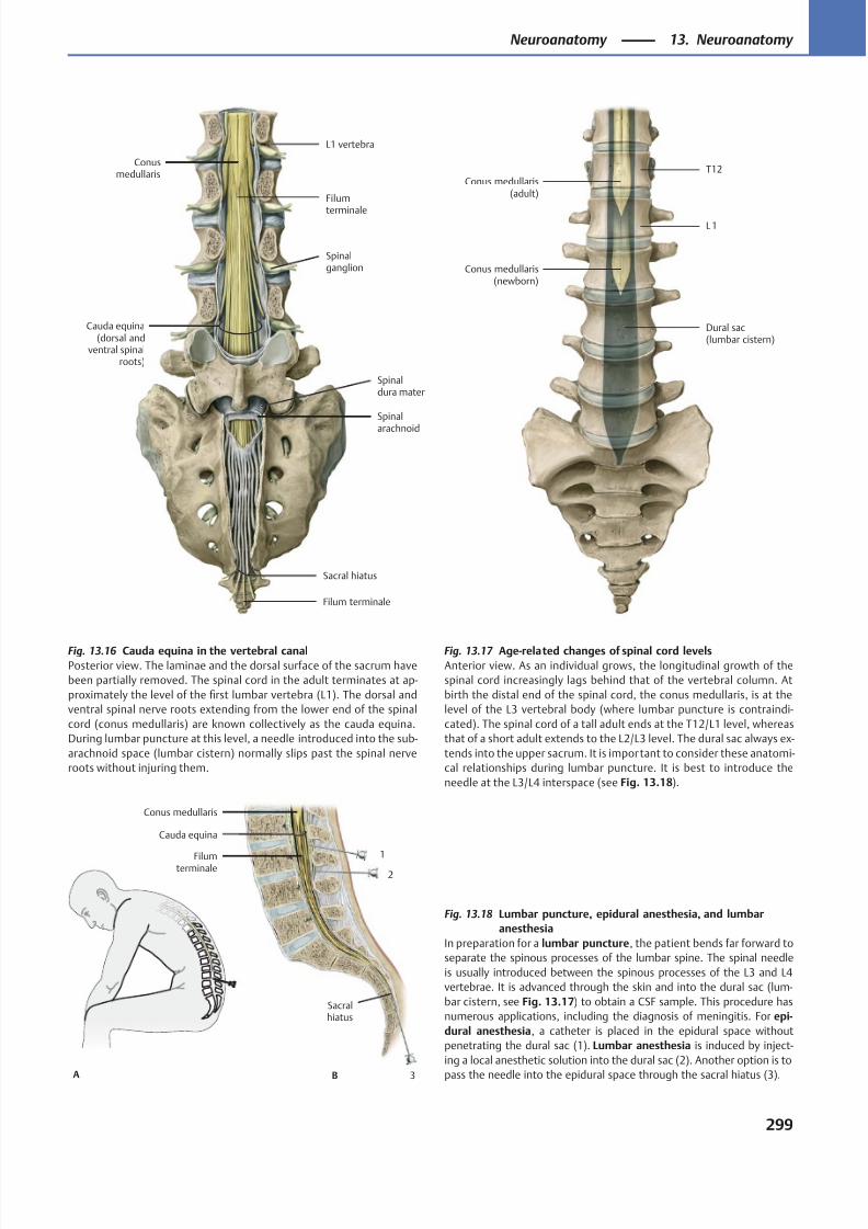
8/15/2019 Head and Neck Anatomy for Dental Medicine - Thieme; (January 26, 2010)
http://slidepdf.com/reader/full/head-and-neck-anatomy-for-dental-medicine-thieme-january-26-2010 312/384
T12
L 1
Conus medullaris(newborn)
Dural sac(lumbar cistern)
Conus medullaris(adult)
Conusmedullaris
Cauda equina(dorsal and
ventral spinalroots)
Sacral hiatus
Spinal
arachnoid
Spinaldura mater
Spinalganglion
L1 vertebra
Filum terminale
Filum
terminale
1
2
3B
Sacralhiatus
Filumterminale
Conus medullaris
Cauda equina
A
Fig. 13.18 Lumbar puncture, epidural anesthesia, and lumbar
anesthesia
In preparation for a lumbar puncture, the patient bends far forward to
separate the spinous processes of the lumbar spine. The spinal needle
is usually introduced between the spinous processes of the L3 and L4
vertebrae. It is advanced through the skin and into the dural sac (lum-
bar cistern, see Fig. 13.17) to obtain a CSF sample. This procedure has
numerous applications, including the diagnosis of meningitis. For epi-
dural anesthesia, a catheter is placed in the epidural space without
penetrating the dural sac (1). Lumbar anesthesia is induced by inject-
ing a local anesthetic solution into the dural sac (2). Another option is to
pass the needle into the epidural space through the sacral hiatus (3).
Fig. 13.17 Age-related changes of spinal cord levels
Anterior view. As an individual grows, the longitudinal growth of the
spinal cord increasingly lags behind that of the vertebral column. At
birth the distal end of the spinal cord, the conus medullaris, is at the
level of the L3 vertebral body (where lumbar puncture is contraindi-
cated). The spinal cord of a tall adult ends at the T12/L1 level, whereas
that of a short adult extends to the L2/L3 level. The dural sac always ex-
tends into the upper sacrum. It is important to consider these anatomi-
cal relationships during lumbar puncture. It is best to introduce the
needle at the L3/L4 interspace (see Fig. 13.18).
Fig. 13.16 Cauda equina in the vertebral canal
Posterior view. The laminae and the dorsal surface of the sacrum have
been partially removed. The spinal cord in the adult terminates at ap-
proximately the level of the first lumbar vertebra (L1). The dorsal and
ventral spinal nerve roots extending from the lower end of the spinal
cord (conus medullaris) are known collectively as the cauda equina.
During lumbar puncture at this level, a needle introduced into the sub-
arachnoid space (lumbar cistern) normally slips past the spinal nerve
roots without injuring them.
299
Neuroanatomy 13. Neuroanatomy
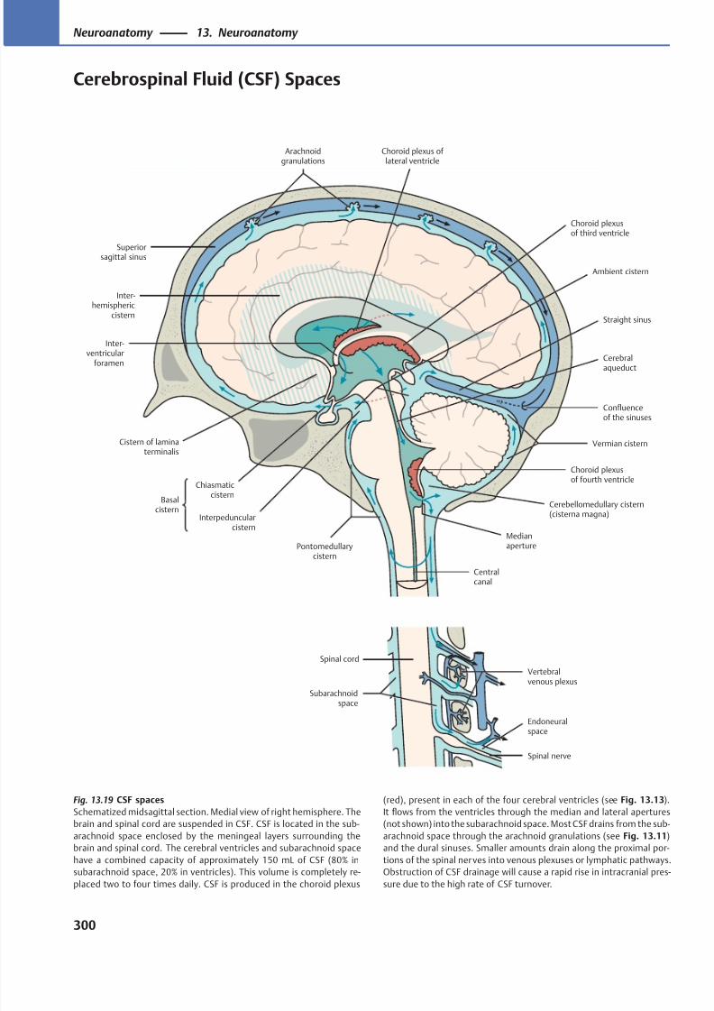
8/15/2019 Head and Neck Anatomy for Dental Medicine - Thieme; (January 26, 2010)
http://slidepdf.com/reader/full/head-and-neck-anatomy-for-dental-medicine-thieme-january-26-2010 313/384
Superiorsagittal sinus
Arachnoidgranulations
Inter-hemispheric
cistern
Choroid plexus of lateral ventricle
Choroid plexusof third ventricle
Ambient cistern
Confluenceof the sinuses
Vermian cistern
Cerebralaqueduct
Choroid plexusof fourth ventricle
Cerebellomedullary cistern(cisterna magna)
MedianaperturePontomedullary
cistern
Interpeduncular
cistern
Chiasmaticcistern
Basalcistern
Inter-
ventricularforamen
Cistern of laminaterminalis
Straight sinus
Centralcanal
Vertebralvenous plexus
Endoneuralspace
Spinal nerve
Spinal cord
Subarachnoidspace
Fig. 13.19 CSF spaces
Schematized midsagittal section. Medial view of right hemisphere. The
brain and spinal cord are suspended in CSF. CSF is located in the sub-
arachnoid space enclosed by the meningeal layers surrounding the
brain and spinal cord. The cerebral ventricles and subarachnoid space
have a combined capacity of approximately 150 mL of CSF (80% in
subarachnoid space, 20% in ventricles). This volume is completely re-
placed two to four times daily. CSF is produced in the choroid plexus
(red), present in each of the four cerebral ventricles (see Fig. 13.13).
It flows from the ventricles through the median and lateral apertures
(not shown) into the subarachnoid space. Most CSF drains from the sub-
arachnoid space through the arachnoid granulations (see Fig. 13.11)
and the dural sinuses. Smaller amounts drain along the proximal por-
tions of the spinal nerves into venous plexuses or lymphatic pathways.
Obstruction of CSF drainage will cause a rapid rise in intracranial pres-
sure due to the high rate of CSF turnover.
300
Neuroanatomy 13. Neuroanatomy
Cerebrospinal Fluid (CSF) Spaces
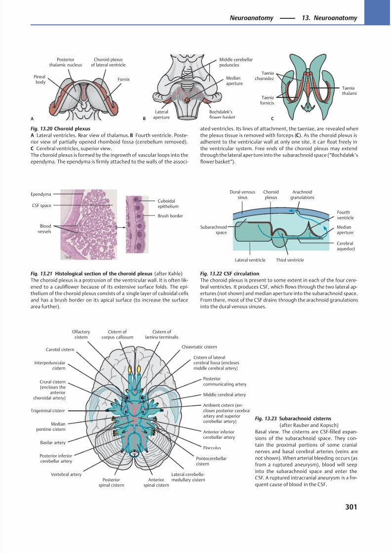
8/15/2019 Head and Neck Anatomy for Dental Medicine - Thieme; (January 26, 2010)
http://slidepdf.com/reader/full/head-and-neck-anatomy-for-dental-medicine-thieme-january-26-2010 314/384
Fornix
Choroid plexusof lateral ventricle
Posteriorthalamic nucleus
Pinealbody
A
Medianaperture
Lateralaperture
Bochdalek’sflower basket
Middle cerebellarpeduncles
B
Taeniachoroidea
Taeniafornicis
Taeniathalami
C
CSF space
Brush border
Bloodvessels
EpendymaCuboidalepithelium
Dural venoussinus Arachnoidgranulations
Third ventricle
Fourthventricle
Cerebralaqueduct
Choroidplexus
Lateral ventricle
Medianaperture
Subarachnoidspace
Cistern of corpus callosum
Olfactorycistern
Cistern of lamina terminalis
Chiasmatic cistern
Cistern of lateralcerebral fossa (enclosesmiddle cerebral artery)
Posteriorcommunicating artery
Middle cerebral artery
Trigeminal cisternAmbient cistern (en-closes posterior cerebralartery and superiorcerebellar artery)
Anterior inferiorcerebellar artery
Pontocerebellarcistern
Flocculus
Lateral cerebello-medullary cisternAnterior
spinal cistern
Posterior
spinal cistern
Vertebral artery
Posterior inferiorcerebellar artery
Basilar artery
Medianpontine cistern
Crural cistern
(encloses theanterior
choroidal artery)
Interpeduncularcistern
Carotid cistern
Fig. 13.20 Choroid plexus
A Lateral ventricles. Rear view of thalamus. B Fourth ventricle. Poste-
rior view of partially opened rhomboid fossa (cerebellum removed).
C Cerebral ventricles, superior view.
The choroid plexus is formed by the ingrowth of vascular loops into the
ependyma. The ependyma is firmly attached to the walls of the associ-
ated ventricles. Its lines of attachment, the taeniae, are revealed when
the plexus tissue is removed with forceps (C). As the choroid plexus is
adherent to the ventricular wall at only one site, it can float freely in
the ventricular system. Free ends of the choroid plexus may extend
through the lateral aper ture into the subarachnoid space (“Bochdalek’s
flower basket”).
Fig. 13.22 CSF circulation
The choroid plexus is present to some extent in each of the four cere-
bral ventricles. It produces CSF, which flows through the two lateral ap-
ertures (not shown) and median aperture into the subarachnoid space.
From there, most of the CSF drains through the arachnoid granulations
into the dural venous sinuses.
Fig. 13.21 Histological section of the choroid plexus (after Kahle)
The choroid plexus is a protrusion of the ventricular wall. It is often lik-
ened to a cauliflower because of its extensive surface folds. The epi-
thelium of the choroid plexus consists of a single layer of cuboidal cells
and has a brush border on its apical surface (to increase the surface
area further).
Fig. 13.23 Subarachnoid cisterns
(after Rauber and Kopsch)
Basal view. The cisterns are CSF-filled expan-
sions of the subarachnoid space. They con-
tain the proximal portions of some cranial
nerves and basal cerebral arteries (veins are
not shown). When arterial bleeding occurs (as
from a ruptured aneurysm), blood will seep
into the subarachnoid space and enter the
CSF. A ruptured intracranial aneurysm is a fre-
quent cause of blood in the CSF.
301
Neuroanatomy 13. Neuroanatomy
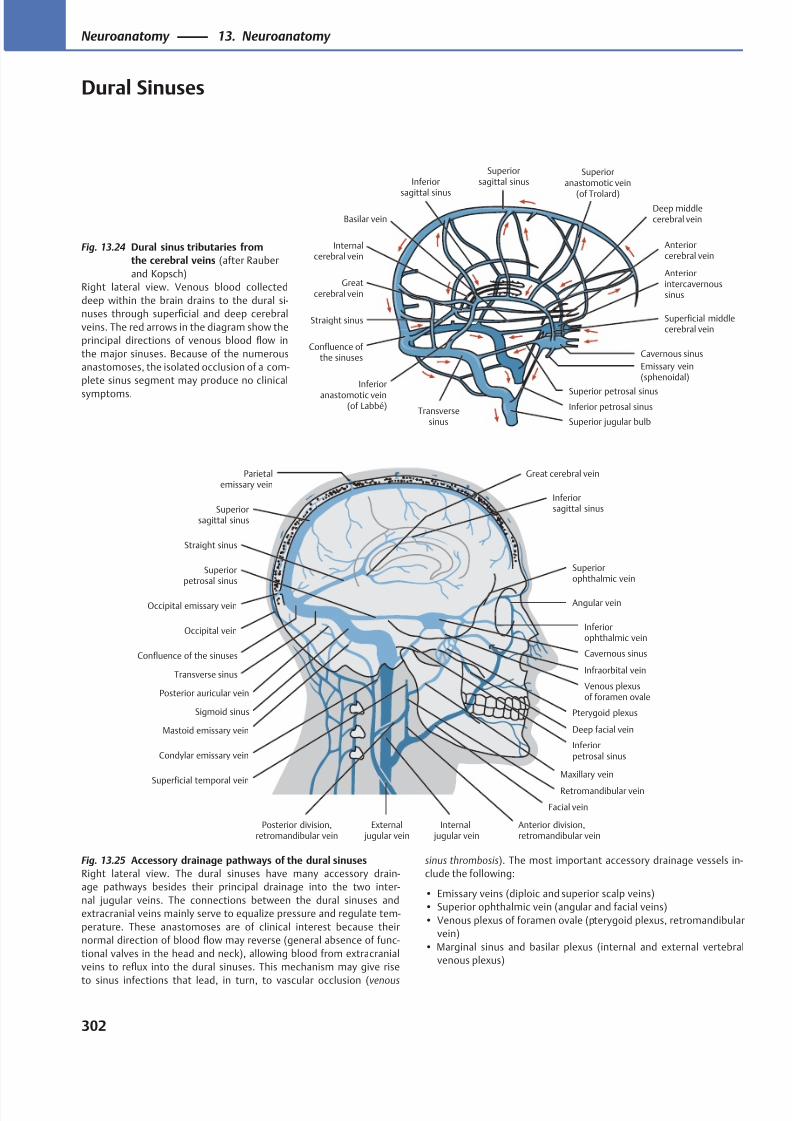
8/15/2019 Head and Neck Anatomy for Dental Medicine - Thieme; (January 26, 2010)
http://slidepdf.com/reader/full/head-and-neck-anatomy-for-dental-medicine-thieme-january-26-2010 315/384
Deep middlecerebral vein
Anteriorcerebral vein
Cavernous sinus
Basilar vein
Inferior petrosal sinus
Superior jugular bulb
Inferior
anastomotic vein(of Labbé)
Transversesinus
Confluence of the sinuses
Straight sinus
Greatcerebral vein
Internalcerebral vein
Inferior
sagittal sinus
Superioranastomotic vein
(of Trolard)
Superiorsagittal sinus
Superficial middlecerebral vein
Anteriorintercavernoussinus
Emissary vein(sphenoidal)
Superior petrosal sinus
Superiorophthalmic vein
Inferiorophthalmic vein
Angular vein
Venous plexusof foramen ovale
Pterygoid plexus
Inferiorpetrosal sinus
Facial vein
External jugular vein
Internal jugular vein
Posterior division,retromandibular vein
Superficial temporal vein
Condylar emissary vein
Sigmoid sinus
Mastoid emissary vein
Posterior auricular vein
Occipital vein
Confluence of the sinuses
Occipital emissary vein
Straight sinus
Superiorsagittal sinus
Parietalemissary vein
Inferiorsagittal sinus
Superiorpetrosal sinus
Great cerebral vein
Cavernous sinus
Maxillary vein
Transverse sinus
Anterior division,retromandibular vein
Retromandibular vein
Deep facial vein
Infraorbital vein
Fig. 13.24 Dural sinus tributaries from
the cerebral veins (after Rauber
and Kopsch)
Right lateral view. Venous blood collected
deep within the brain drains to the dural si-
nuses through superficial and deep cerebral
veins. The red arrows in the diagram show the
principal directions of venous blood flow in
the major sinuses. Because of the numerous
anastomoses, the isolated occlusion of a com-
plete sinus segment may produce no clinical
symptoms.
Fig. 13.25 Accessory drainage pathways of the dural sinuses
Right lateral view. The dural sinuses have many accessory drain-
age pathways besides their principal drainage into the two inter-
nal jugular veins. The connections between the dural sinuses and
extracranial veins mainly serve to equalize pressure and regulate tem-
perature. These anastomoses are of clinical interest because their
normal direction of blood flow may reverse (general absence of func-
tional valves in the head and neck), allowing blood from extracranial
veins to reflux into the dural sinuses. This mechanism may give rise
to sinus infections that lead, in turn, to vascular occlusion (venous
sinus thrombosis). The most important accessory drainage vessels in-
clude the following:
• Emissary veins (diploic and superior scalp veins)
• Superior ophthalmic vein (angular and facial veins)
• Venous plexus of foramen ovale (pterygoid plexus, retromandibular
vein)
• Marginal sinus and basilar plexus (internal and external vertebral
venous plexus)
302
Neuroanatomy 13. Neuroanatomy
Dural Sinuses
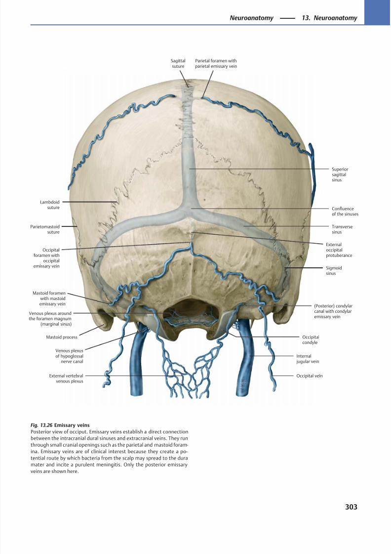
8/15/2019 Head and Neck Anatomy for Dental Medicine - Thieme; (January 26, 2010)
http://slidepdf.com/reader/full/head-and-neck-anatomy-for-dental-medicine-thieme-january-26-2010 316/384
External vertebralvenous plexus
Venous plexusof hypoglossal
nerve canal
Venous plexus aroundthe foramen magnum
(marginal sinus)
Confluenceof the sinuses
Superiorsagittalsinus
Occipital vein
Sagittalsuture
Parietal foramen withparietal emissary vein
(Posterior) condylarcanal with condylaremissary vein
Occipitalcondyle
Mastoid process
Mastoid foramenwith mastoidemissary vein
Occipitalforamen with
occipitalemissary vein
Parietomastoidsuture
Externaloccipitalprotuberance
Transversesinus
Sigmoidsinus
Internal jugular vein
Lambdoidsuture
Fig. 13.26 Emissary veins
Posterior view of occiput. Emissary veins establish a direct connection
between the intracranial dural sinuses and extracranial veins. They run
through small cranial openings such as the parietal and mastoid foram-
ina. Emissary veins are of clinical interest because they create a po-
tential route by which bacteria from the scalp may spread to the dura
mater and incite a purulent meningitis. Only the posterior emissary
veins are shown here.
303
Neuroanatomy 13. Neuroanatomy
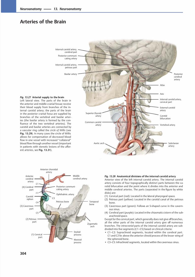
8/15/2019 Head and Neck Anatomy for Dental Medicine - Thieme; (January 26, 2010)
http://slidepdf.com/reader/full/head-and-neck-anatomy-for-dental-medicine-thieme-january-26-2010 317/384
Internal carotid artery,cerebral part
External carotidartery
Superior thyroidartery
Aortic arch
Axis
Internal carotid artery,cervical part
Internal carotid artery,petrous part
Atlas
Basilar artery
Vertebral artery
Subclavian
artery
Posteriorcerebralartery
Posterior communi-cating artery
Common carotidartery
Carotidbifurcation
Mastoid
process
Styloidprocess
Zygomaticarch
Temporalbone
Petrous bone
Carotidsiphon
Ophthalmic artery
Posterior communi-cating artery
Anterior choroidalartery
Middlecerebral artery
Anteriorcerebral
artery
(1) Cervicalpart
(2) Petrouspart
(3) Cavernouspart
(4) Cerebralpart
C1
C2
C3
C4
C5
Fig. 13.27 Arterial supply to the brainLeft lateral view. The parts of the brain in
the anterior and middle cranial fossae receive
their blood supply from branches of the in-
ternal carotid artery; the parts of the brain
in the posterior cranial fossa are supplied by
branches of the vertebral and basilar arter-
ies (the basilar artery is formed by the con-
fluence of the two vertebral arteries). The
carotid and basilar arteries are connected by
a vascular ring called the circle of Willis (see
Fig. 13.29). In many cases the circle of Willis
allows for compensation of decreased blood
flow in one vessel with increased “collateral”
blood flow through another vessel (important
in patients with stenotic lesions of the aff er-
ent arteries, see Fig. 13.31).
Fig. 13.28 Anatomical divisions of the internal carotid artery
Anterior view of the left internal carotid artery. The internal carotid
artery consists of four topographically distinct parts between the ca-
rotid bifurcation and the point where it divides into the anterior and
middle cerebral arteries. The parts (separated in the figure by white
disks) are:(1) Cervical part (red): Located in the lateral pharyngeal space.
(2) Petrous part (yellow): Located in the carotid canal of the petrous
bone.
(3) Cavernous part (green): Follows an S-shaped curve in the cavern-
ous sinus.
(4) Cerebral part (purple): Located in the chiasmatic cistern of the sub-
arachnoid space.
Except for the cervical part, which generally does not give off branches,
all the other parts of the internal carotid artery give off numerous
branches. The intracranial parts of the internal carotid artery are sub-
divided into five segments (C1–C5) based on clinical criteria:
• C1–C2: Supraclinoid segments, located within the cerebral part.
C1 and C2 lie above the anterior clinoid process of the lesser wing of
the sphenoid bone.
• C3–C5: Infraclinoid segments, located within the cavernous sinus.
304
Neuroanatomy 13. Neuroanatomy
Arteries of the Brain
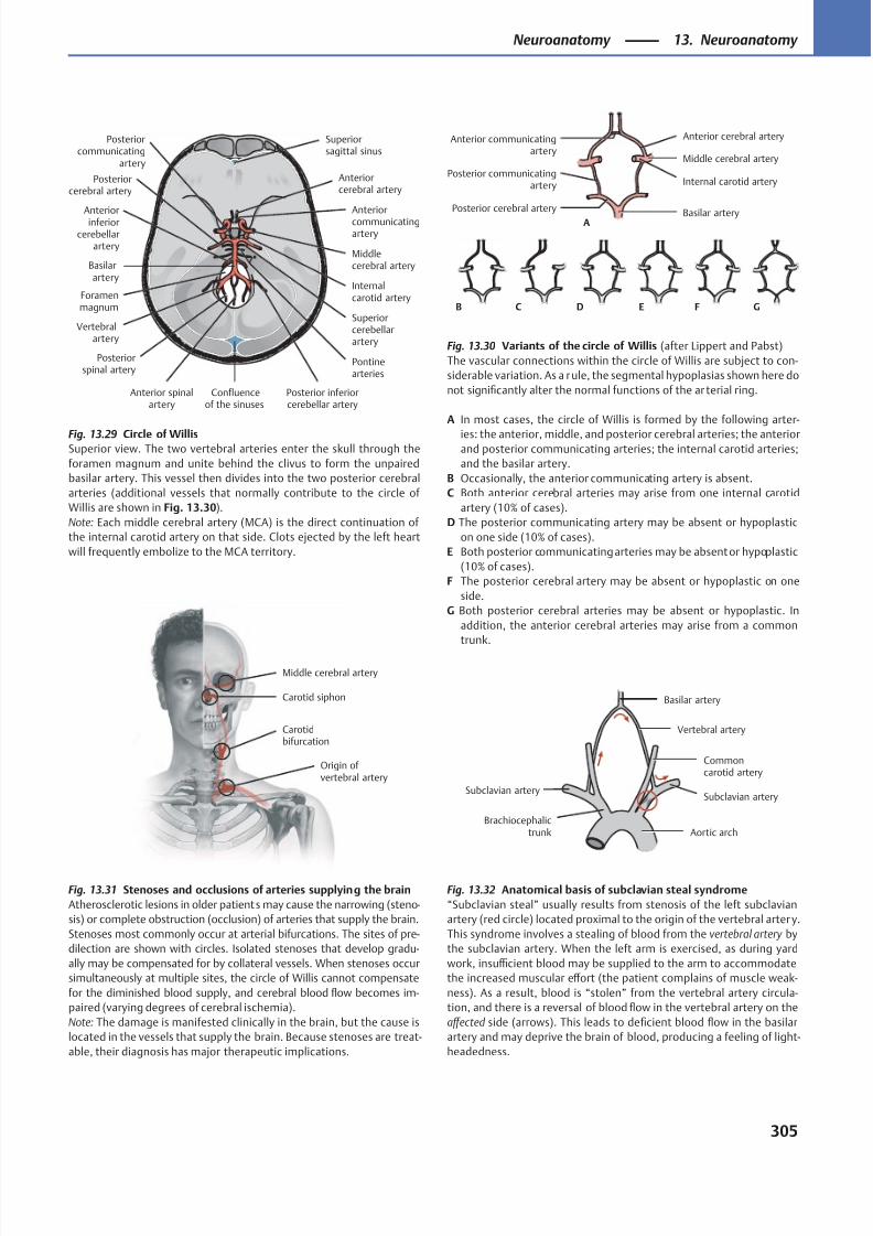
8/15/2019 Head and Neck Anatomy for Dental Medicine - Thieme; (January 26, 2010)
http://slidepdf.com/reader/full/head-and-neck-anatomy-for-dental-medicine-thieme-january-26-2010 318/384
Foramenmagnum
Confluenceof the sinuses
Basilarartery
Superiorsagittal sinus
Posteriorcommunicating
artery
Posteriorcerebral artery
Anteriorinferior
cerebellarartery
Vertebralartery
Posteriorspinal artery
Anterior spinalartery
Posterior inferiorcerebellar artery
Pontinearteries
Superiorcerebellarartery
Internalcarotid artery
Middlecerebral artery
Anteriorcommunicatingartery
Anteriorcerebral artery
Origin ofvertebral artery
Carotidbifurcation
Carotid siphon
Middle cerebral artery
Subclavian artery
Brachiocephalictrunk Aortic arch
Subclavian artery
Commoncarotid artery
Vertebral artery
Basilar artery
Basilar arteryPosterior cerebral artery
Posterior communicatingartery
Middle cerebral artery
Internal carotid artery
Anterior cerebral arteryAnterior communicatingartery
A
B C D E F G
Fig. 13.29 Circle of WillisSuperior view. The two vertebral arteries enter the skull through the
foramen magnum and unite behind the clivus to form the unpaired
basilar artery. This vessel then divides into the two posterior cerebral
arteries (additional vessels that normally contribute to the circle of
Willis are shown in Fig. 13.30).
Note: Each middle cerebral artery (MCA) is the direct continuation of
the internal carotid artery on that side. Clots ejected by the left heart
will frequently embolize to the MCA territory.
Fig. 13.30 Variants of the circle of Willis (after Lippert and Pabst)
The vascular connections within the circle of Willis are subject to con-
siderable variation. As a rule, the segmental hypoplasias shown here do
not significantly alter the normal functions of the ar terial ring.
A In most cases, the circle of Willis is formed by the following arter-
ies: the anterior, middle, and posterior cerebral arteries; the anteriorand posterior communicating arteries; the internal carotid arteries;
and the basilar artery.
B Occasionally, the anterior communicating artery is absent.
C Both anterior cerebral arteries may arise from one internal carotid
artery (10% of cases).
D The posterior communicating artery may be absent or hypoplastic
on one side (10% of cases).
E Both posterior communicating arteries may be absent or hypoplastic
(10% of cases).
F The posterior cerebral artery may be absent or hypoplastic on one
side.
G Both posterior cerebral arteries may be absent or hypoplastic. In
addition, the anterior cerebral arteries may arise from a common
trunk.
Fig. 13.31 Stenoses and occlusions of arteries supplying the brain
Atherosclerotic lesions in older patients may cause the narrowing (steno-
sis) or complete obstruction (occlusion) of arteries that supply the brain.
Stenoses most commonly occur at arterial bifurcations. The sites of pre-
dilection are shown with circles. Isolated stenoses that develop gradu-
ally may be compensated for by collateral vessels. When stenoses occur
simultaneously at multiple sites, the circle of Willis cannot compensate
for the diminished blood supply, and cerebral blood flow becomes im-
paired (varying degrees of cerebral ischemia).
Note: The damage is manifested clinically in the brain, but the cause is
located in the vessels that supply the brain. Because stenoses are treat-
able, their diagnosis has major therapeutic implications.
Fig. 13.32 Anatomical basis of subclavian steal syndrome
“Subclavian steal” usually results from stenosis of the left subclavian
artery (red circle) located proximal to the origin of the vertebral arter y.
This syndrome involves a stealing of blood from the vertebral artery by
the subclavian artery. When the left arm is exercised, as during yard
work, insuffi cient blood may be supplied to the arm to accommodate
the increased muscular eff ort (the patient complains of muscle weak-
ness). As a result, blood is “stolen” from the vertebral artery circula-
tion, and there is a reversal of blood flow in the vertebral artery on the
aff ected side (arrows). This leads to deficient blood flow in the basilar
artery and may deprive the brain of blood, producing a feeling of light-
headedness.
305
Neuroanatomy 13. Neuroanatomy
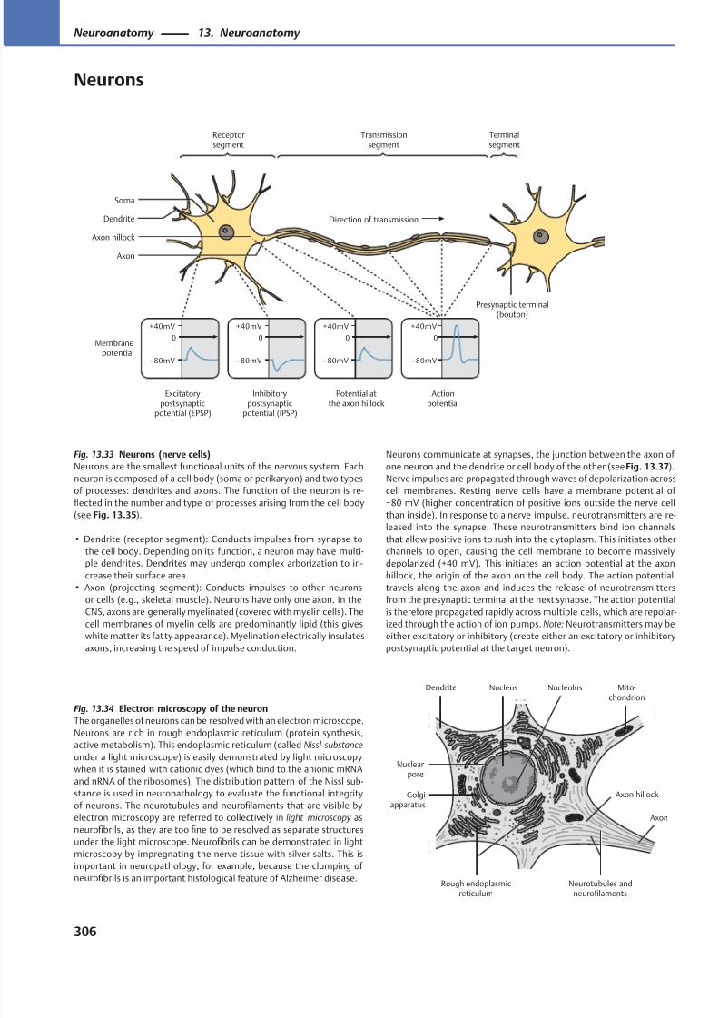
8/15/2019 Head and Neck Anatomy for Dental Medicine - Thieme; (January 26, 2010)
http://slidepdf.com/reader/full/head-and-neck-anatomy-for-dental-medicine-thieme-january-26-2010 319/384
Excitatorypostsynaptic
potential (EPSP)
Inhibitorypostsynaptic
potential (IPSP)
Potential atthe axon hillock
Actionpotential
Membrane
potential
Direction of transmission
Terminalsegment
Transmissionsegment
Receptorsegment
Axon
Axon hillock
Soma
Dendrite
Presynaptic terminal(bouton)
Neurotubules and
neurofilaments
Nuclearpore
Golgiapparatus
Dendrite
Axon hillock
Mito-chondrion
Rough endoplasmic
reticulum
Axon
NucleolusNucleus
Fig. 13.33 Neurons (nerve cells)
Neurons are the smallest functional units of the nervous system. Each
neuron is composed of a cell body (soma or perikaryon) and two types
of processes: dendrites and axons. The function of the neuron is re-
flected in the number and type of processes arising from the cell body
(see Fig. 13.35).
• Dendrite (receptor segment): Conducts impulses from synapse to
the cell body. Depending on its function, a neuron may have multi-
ple dendrites. Dendrites may undergo complex arborization to in-
crease their surface area.
• Axon (projecting segment): Conducts impulses to other neurons
or cells (e.g., skeletal muscle). Neurons have only one axon. In the
CNS, axons are generally myelinated (covered with myelin cells). The
cell membranes of myelin cells are predominantly lipid (this gives
white matter its fat ty appearance). Myelination electrically insulates
axons, increasing the speed of impulse conduction.
Fig. 13.34 Electron microscopy of the neuronThe organelles of neurons can be resolved with an electron microscope.
Neurons are rich in rough endoplasmic reticulum (protein synthesis,
active metabolism). This endoplasmic reticulum (called Nissl substance
under a light microscope) is easily demonstrated by light microscopy
when it is stained with cationic dyes (which bind to the anionic mRNA
and nRNA of the ribosomes). The distribution pattern of the Nissl sub-
stance is used in neuropathology to evaluate the functional integrity
of neurons. The neurotubules and neurofilaments that are visible by
electron microscopy are referred to collectively in light microscopy as
neurofibrils, as they are too fine to be resolved as separate structures
under the light microscope. Neurofibrils can be demonstrated in light
microscopy by impregnating the nerve tissue with silver salts. This is
important in neuropathology, for example, because the clumping of
neurofibrils is an important histological feature of Alzheimer disease.
Neurons communicate at synapses, the junction between the axon of
one neuron and the dendrite or cell body of the other (see Fig. 13.37).
Nerve impulses are propagated through waves of depolarization across
cell membranes. Resting nerve cells have a membrane potential of
−80 mV (higher concentration of positive ions outside the nerve cell
than inside). In response to a nerve impulse, neurotransmitters are re-
leased into the synapse. These neurotransmitters bind ion channels
that allow positive ions to rush into the c ytoplasm. This initiates other
channels to open, causing the cell membrane to become massively
depolarized (+40 mV). This initiates an action potential at the axon
hillock, the origin of the axon on the cell body. The action potential
travels along the axon and induces the release of neurotransmitters
from the presynaptic terminal at the next synapse. The action potential
is therefore propagated rapidly across multiple cells, which are repolar-
ized through the action of ion pumps. Note: Neurotransmitters may be
either excitatory or inhibitory (create either an excitatory or inhibitory
postsynaptic potential at the target neuron).
306
Neuroanatomy 13. Neuroanatomy
Neurons
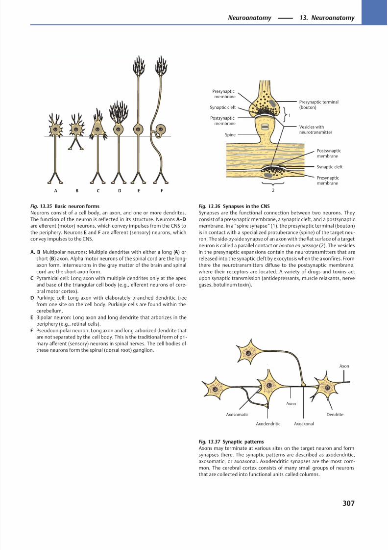
8/15/2019 Head and Neck Anatomy for Dental Medicine - Thieme; (January 26, 2010)
http://slidepdf.com/reader/full/head-and-neck-anatomy-for-dental-medicine-thieme-january-26-2010 320/384
A B C D E F
Presynaptic terminal(bouton)
Postsynapticmembrane
Synaptic cleft
Presynapticmembrane
2
1Postsynaptic
membrane
Synaptic cleft
Presynaptic
membrane
Vesicles withneurotransmitter
Spine
Axon
Axosomatic
Axodendritic
Axon
Dendrite
Axoaxonal
Fig. 13.35 Basic neuron forms
Neurons consist of a cell body, an axon, and one or more dendrites.
The function of the neuron is reflected in its structure. Neurons A–D
are eff erent (motor) neurons, which convey impulses from the CNS to
the periphery. Neurons E and F are aff erent (sensory) neurons, which
convey impulses to the CNS.
A, B Multipolar neurons: Multiple dendrites with either a long (A) or
short (B) axon. Alpha motor neurons of the spinal cord are the long-
axon form. Interneurons in the gray matter of the brain and spinal
cord are the short-axon form.
C Pyramidal cell: Long axon with multiple dendrites only at the apex
and base of the triangular cell body (e.g., eff erent neurons of cere-
bral motor cortex).
D Purkinje cell: Long axon with elaborately branched dendritic tree
from one site on the cell body. Purkinje cells are found within the
cerebellum.
E Bipolar neuron: Long axon and long dendrite that arborizes in the
periphery (e.g., retinal cells).
F Pseudounipolar neuron: Long axon and long arborized dendrite that
are not separated by the cell body. This is the traditional form of pri-
mary aff erent (sensory) neurons in spinal nerves. The cell bodies of
these neurons form the spinal (dorsal root) ganglion.
Fig. 13.36 Synapses in the CNS
Synapses are the functional connection between two neurons. They
consist of a presynaptic membrane, a synaptic cleft, and a postsynaptic
membrane. In a “spine synapse” (1), the presynaptic terminal (bouton)
is in contact with a specialized protuberance (spine) of the target neu-
ron. The side-by-side synapse of an axon with the flat surface of a target
neuron is called a parallel contact or bouton en passage (2). The vesicles
in the presynaptic expansions contain the neurotransmitters that are
released into the synaptic cleft by exocytosis when the axon fires. From
there the neurotransmitters diff use to the postsynaptic membrane,
where their receptors are located. A variety of drugs and toxins act
upon synaptic transmission (antidepressants, muscle relaxants, nerve
gases, botulinum toxin).
Fig. 13.37 Synaptic patterns
Axons may terminate at various sites on the target neuron and form
synapses there. The synaptic patterns are described as axodendritic,
axosomatic, or axoaxonal. Axodendritic synapses are the most com-
mon. The cerebral cortex consists of many small groups of neurons
that are collected into functional units called columns.
307
Neuroanatomy 13. Neuroanatomy
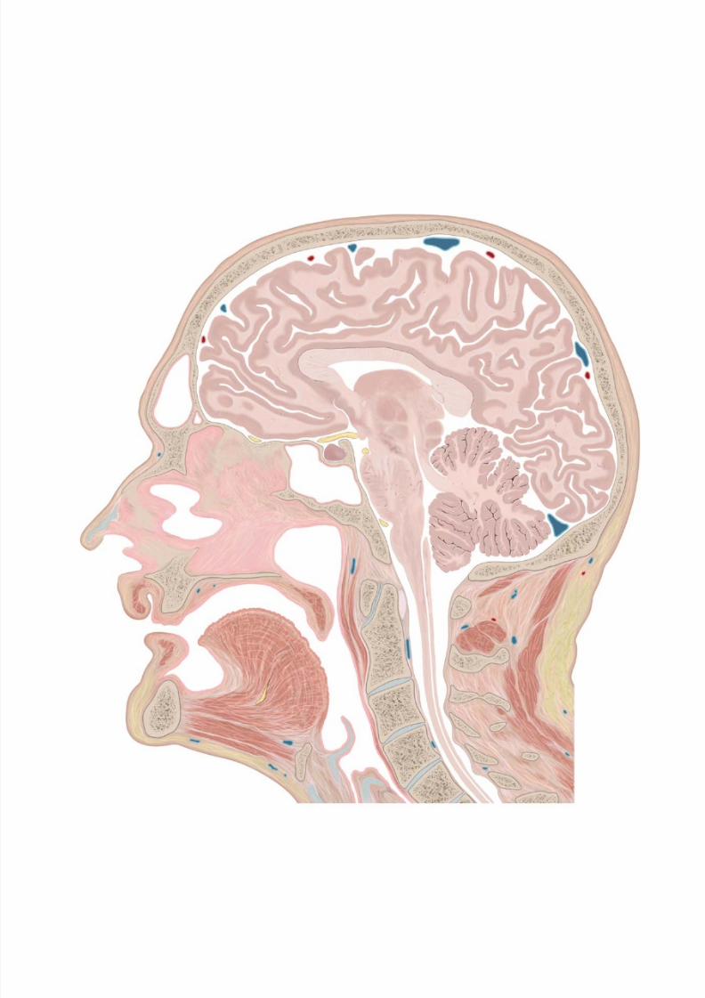
8/15/2019 Head and Neck Anatomy for Dental Medicine - Thieme; (January 26, 2010)
http://slidepdf.com/reader/full/head-and-neck-anatomy-for-dental-medicine-thieme-january-26-2010 321/384
8/15/2019 Head and Neck Anatomy for Dental Medicine - Thieme; (January 26, 2010)
http://slidepdf.com/reader/full/head-and-neck-anatomy-for-dental-medicine-thieme-january-26-2010 322/384
Sectional Anatomy
14 Sectional Anatomy of the Head & Neck
Coronal Sections of the Head (I): Anterior . . . . . . . . . . . . . . .310
Coronal Sections of the Head (II): Posterior . . . . . . . . . . . . .312
Coronal MRIs of the Head . . . . . . . . . . . . . . . . . . . . . . . . . . . .314
Coronal MRIs of the Neck (I): Anterior . . . . . . . . . . . . . . . . . .316
Coronal MRIs of the Neck (II) . . . . . . . . . . . . . . . . . . . . . . . . . 318
Coronal MRIs of the Neck (III): Posterior . . . . . . . . . . . . . . . . 320
Transverse Sections of the Head (I): Cranial . . . . . . . . . . . . .322
Transverse Sections of the Head (II) . . . . . . . . . . . . . . . . . . . . 324Transverse Sections of the Head (III): Caudal . . . . . . . . . . . .326
Transverse Sections of the Neck (I): Cranial . . . . . . . . . . . . . . 328
Transverse Sections of the Neck (II): Caudal . . . . . . . . . . . . . 330
Transverse MRIs of the Head . . . . . . . . . . . . . . . . . . . . . . . . . . 332
Transverse MRIs of the Oral Cavity . . . . . . . . . . . . . . . . . . . . . 334
Transverse MRIs of the Neck . . . . . . . . . . . . . . . . . . . . . . . . . . 336
Sagittal Sections of the Head (I): Medial . . . . . . . . . . . . . . . .338
Sagittal Sections of the Head (II): Lateral. . . . . . . . . . . . . . . . 340
Sagittal MRIs of the Head . . . . . . . . . . . . . . . . . . . . . . . . . . . .342
Sagittal MRIs of the Neck . . . . . . . . . . . . . . . . . . . . . . . . . . . .344
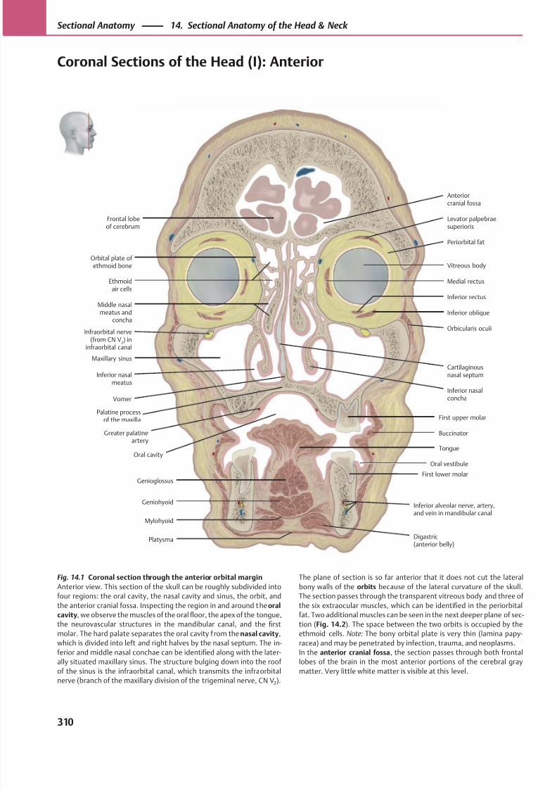
8/15/2019 Head and Neck Anatomy for Dental Medicine - Thieme; (January 26, 2010)
http://slidepdf.com/reader/full/head-and-neck-anatomy-for-dental-medicine-thieme-january-26-2010 323/384
Palatine processof the maxilla
Orbital plate of ethmoid bone
Buccinator
Inferior nasalconcha
Middle nasalmeatus and
concha
Greater palatineartery
Oral cavityTongue
Digastric(anterior belly)
Anteriorcranial fossa
Oral vestibule
First lower molar
First upper molar
Vomer
Orbicularis oculi
Inferior oblique
Inferior rectus
Periorbital fat
Vitreous body
Levator palpebraesuperioris
Ethmoid air cells
Inferior nasalmeatus
Maxillary sinus
Infraorbital nerve(from CN V
2) in
infraorbital canal
Inferior alveolar nerve, artery,and vein in mandibular canal
Mylohyoid
Genioglossus
Geniohyoid
Cartilaginousnasal septum
Platysma
Medial rectus
Frontal lobeof cerebrum
Fig. 14.1 Coronal section through the anterior orbital margin
Anterior view. This section of the skull can be roughly subdivided into
four regions: the oral cavity, the nasal cavity and sinus, the orbit, and
the anterior cranial fossa. Inspecting the region in and around the oral
cavity, we observe the muscles of the oral floor, the apex of the tongue,
the neurovascular structures in the mandibular canal, and the first
molar. The hard palate separates the oral cavity f rom the nasal cavity,
which is divided into left and right halves by the nasal septum. The in-
ferior and middle nasal conchae can be identified along with the later-
ally situated maxillary sinus. The structure bulging down into the roof
of the sinus is the infraorbital canal, which transmits the infra orbital
nerve (branch of the maxillary division of the trigeminal nerve, CN V2).
The plane of section is so far anterior that it does not cut the lateral
bony walls of the orbits because of the lateral curvature of the skull.
The section passes through the transparent vitreous body and three of
the six extraocular muscles, which can be identified in the periorbital
fat. Two additional muscles can be seen in the next deeper plane of sec-
tion (Fig. 14.2). The space between the two orbits is occupied by the
ethmoid cells. Note: The bony orbital plate is very thin (lamina papy-
racea) and may be penetrated by infection, trauma, and neoplasms.
In the anterior cranial fossa, the section passes through both frontal
lobes of the brain in the most anterior portions of the cerebral gray
matter. Very little white matter is visible at this level.
310
Sectional Anatomy 14. Sectional Anatomy of the Head & Neck
Coronal Sections of the Head (I): Anterior
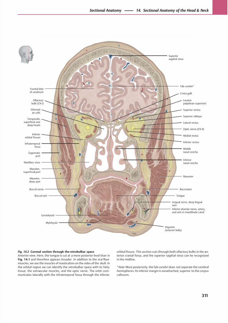
8/15/2019 Head and Neck Anatomy for Dental Medicine - Thieme; (January 26, 2010)
http://slidepdf.com/reader/full/head-and-neck-anatomy-for-dental-medicine-thieme-january-26-2010 324/384
Olfactorybulb (CN I)
Zygomaticarch
Buccinator
Digastric(anterior belly)
TongueBuccal vein
Buccal nerve
Masseter
Inferiornasal concha
Middlenasal concha
Inferiororbital fissure
Inferior rectus
Medial rectus
Temporalis,superficial and
deep headsLateral rectus
Optic nerve (CN II)
Superior rectus
Levatorpalpebrae superioris
Superior oblique
Superiorsagittal sinus
Ethmoid
air cells
Masseter,superficial part
Masseter,deep part
Maxillary sinus
Inferior alveolar nerve, artery,and vein in mandibular canal
Frontal lobeof cerebrum
Crista galli
Falx cerebri*
Lingual nerve, deep lingualvein
Mylohyoid
Geniohyoid
Infratemporalfossa
Fig. 14.2 Coronal section through the retrobulbar space
Anterior view. Here, the tongue is cut at a more posterior level than in
Fig. 14.1 and therefore appears broader. In addition to the oral floor
muscles, we see the muscles of mastication on the sides of the skull. In
the orbital region we can identify the retrobulbar space with its fatty
tissue, the extraocular muscles, and the optic nerve. The orbit com-
municates laterally with the infratemporal fossa through the inferior
orbital fissure. This section cuts through both olfactory bulbs in the an-
terior cranial fossa, and the superior sagittal sinus can be recognized
in the midline.
*Note: More posteriorly, the falx cerebri does not separate the cerebral
hemispheres. Its inferior margin is nonattached, superior to the corpus
callosum.
311
Sectional Anatomy 14. Sectional Anatomy of the Head & Neck
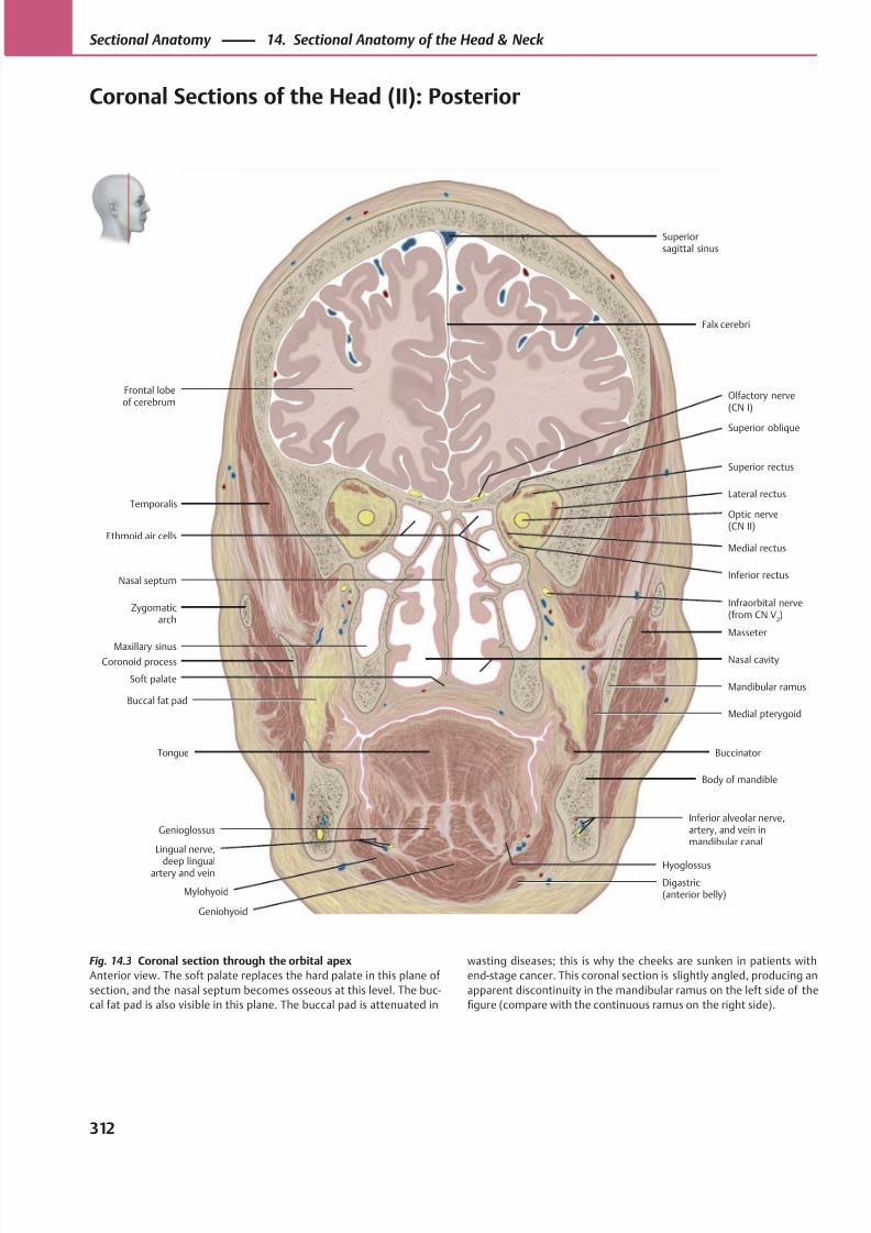
8/15/2019 Head and Neck Anatomy for Dental Medicine - Thieme; (January 26, 2010)
http://slidepdf.com/reader/full/head-and-neck-anatomy-for-dental-medicine-thieme-january-26-2010 325/384
Digastric(anterior belly)
Soft palate
Inferior rectus
Lateral rectus
Optic nerve(CN II)
Superior rectus
Superior oblique
Frontal lobeof cerebrum
Medial rectus
Superiorsagittal sinus
Inferior alveolar nerve,artery, and vein inmandibular canal
Genioglossus
Mylohyoid
Buccal fat pad
Maxillary sinus
Zygomaticarch
Nasal septum
Olfactory nerve(CN I)
Falx cerebri
Infraorbital nerve(from CN V
2)
Buccinator
Body of mandible
Medial pterygoid
Mandibular ramus
Nasal cavity
Masseter
Tongue
Geniohyoid
Temporalis
Ethmoid air cells
Coronoid process
Lingual nerve,
deep lingualartery and vein
Hyoglossus
Fig. 14.3 Coronal section through the orbital apex
Anterior view. The soft palate replaces the hard palate in this plane of
section, and the nasal septum becomes osseous at this level. The buc-
cal fat pad is also visible in this plane. The buccal pad is attenuated in
wasting diseases; this is why the cheeks are sunken in patients with
end-stage cancer. This coronal section is slightly angled, producing an
apparent discontinuity in the mandibular ramus on the left side of the
figure (compare with the continuous ramus on the right side).
312
Sectional Anatomy 14. Sectional Anatomy of the Head & Neck
Coronal Sections of the Head (II): Posterior
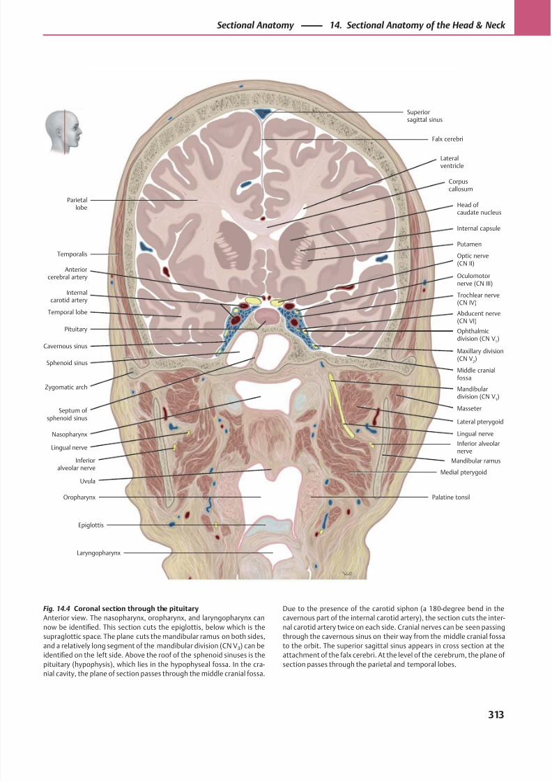
8/15/2019 Head and Neck Anatomy for Dental Medicine - Thieme; (January 26, 2010)
http://slidepdf.com/reader/full/head-and-neck-anatomy-for-dental-medicine-thieme-january-26-2010 326/384
Parietallobe
Temporal lobe
Maxillary division(CN V
2)
Abducent nerve(CN VI)
Ophthalmicdivision (CN V
1)
Trochlear nerve(CN IV)
Oculomotornerve (CN III)
Superiorsagittal sinus
Middle cranialfossa
Anteriorcerebral artery
Sphenoid sinus
Nasopharynx
Uvula
Palatine tonsilOropharynx
Epiglottis
Laryngopharynx
Lingual nerve
Medial pterygoid
Mandibular ramus
Masseter
Lateral pterygoid
Inferior alveolarnerve
Zygomatic arch
Pituitary
Internalcarotid artery
Optic nerve(CN II)
Putamen
Internal capsule
Head of caudate nucleus
Corpuscallosum
Lateralventricle
Falx cerebri
Septum of sphenoid sinus
Cavernous sinus
Temporalis
Lingual nerve
Inferioralveolar nerve
Mandibulardivision (CN V
3)
Fig. 14.4 Coronal section through the pituitary
Anterior view. The nasopharynx, oropharynx, and laryngopharynx can
now be identified. This section cuts the epiglottis, below which is the
supraglottic space. The plane cuts the mandibular ramus on both sides,
and a relatively long segment of the mandibular division (CN V3) can be
identified on the left side. Above the roof of the sphenoid sinuses is the
pituitary (hypophysis), which lies in the hypophyseal fossa. In the cra-
nial cavity, the plane of section passes through the middle cranial fossa.
Due to the presence of the carotid siphon (a 180-degree bend in the
cavernous part of the internal carotid artery), the section cuts the inter-
nal carotid artery twice on each side. Cranial nerves can be seen passing
through the cavernous sinus on their way from the middle cranial fossa
to the orbit. The superior sagittal sinus appears in cross section at the
attachment of the falx cerebri. At the level of the cerebrum, the plane of
section passes through the parietal and temporal lobes.
313
Sectional Anatomy 14. Sectional Anatomy of the Head & Neck
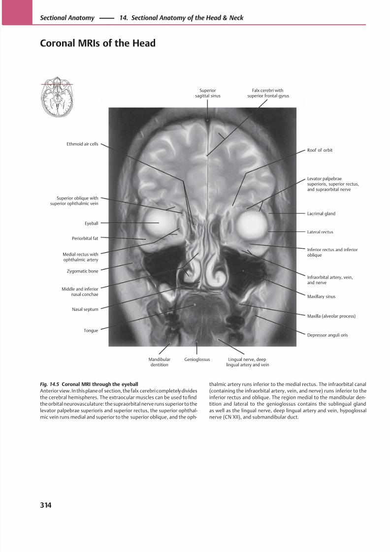
8/15/2019 Head and Neck Anatomy for Dental Medicine - Thieme; (January 26, 2010)
http://slidepdf.com/reader/full/head-and-neck-anatomy-for-dental-medicine-thieme-january-26-2010 327/384
Superior
sagittal sinus
Roof of orbit
Falx cerebri with
superior frontal gyrus
Levator palpebraesuperioris, superior rectus,and supraorbital nerve
Lacrimal gland
Lateral rectus
Inferior rectus and inferioroblique
Infraorbital artery, vein,and nerve
Maxillary sinus
Maxilla (alveolar process)
Depressor anguli oris
Lingual nerve, deeplingual artery and vein
GenioglossusMandibulardentition
Ethmoid air cells
Superior oblique withsuperior ophthalmic vein
Eyeball
Periorbital fat
Medial rectus withophthalmic artery
Zygomatic bone
Middle and inferiornasal conchae
Nasal septum
Tongue
Fig. 14.5 Coronal MRI through the eyeballAnterior view. In this plane of section, the falx cerebri completely divides
the cerebral hemispheres. The extraocular muscles can be used to find
the orbital neurovasculature: the supraorbital nerve runs superior to the
levator palpebrae superioris and superior rectus, the superior ophthal-
mic vein runs medial and superior to the superior oblique, and the oph-
thalmic artery runs inferior to the medial rectus. The infraorbital canal(containing the infraorbital artery, vein, and nerve) runs inferior to the
inferior rectus and oblique. The region medial to the mandibular den-
tition and lateral to the genioglossus contains the sublingual gland
as well as the lingual nerve, deep lingual artery and vein, hypoglossal
nerve (CN XII), and submandibular duct.
314
Sectional Anatomy 14. Sectional Anatomy of the Head & Neck
Coronal MRIs of the Head
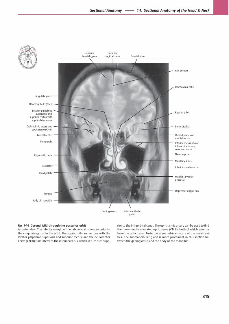
8/15/2019 Head and Neck Anatomy for Dental Medicine - Thieme; (January 26, 2010)
http://slidepdf.com/reader/full/head-and-neck-anatomy-for-dental-medicine-thieme-january-26-2010 328/384
Cingulate gyrus
Falx cerebri
Superior
frontal gyrus
Superior
sagittal sinus Frontal bone
Ethmoid air cells
Nasal septum
Periorbital fat
Orbital plate andmedial rectus
Inferior rectus aboveinfraorbital artery,vein, and nerve
Roof of orbit
Maxillary sinus
Inferior nasal concha
Maxilla (alveolarprocess)
Body of mandible
Genioglossus Submandibulargland
Depressor anguli oris
Olfactory bulb (CN I)
Levator palpebrae
superioris andsuperior rectus with
supraorbital nerve
Ophthalmic artery andoptic nerve (CN II)
Lateral rectus
Temporalis
Zygomatic bone
Masseter
Hard palate
Tongue
Fig. 14.6 Coronal MRI through the posterior orbitAnterior view. The inferior margin of the falx cerebri is now superior to
the cingulate gyrus. In the orbit, the supraorbital nerve runs with the
levator palpebrae superioris and superior rectus, and the oculomotor
nerve (CN III) runs lateral to the inferior rec tus, which in turn runs supe-
rior to the infraorbital canal. The ophthalmic artery can be used tofi
ndthe more medially located optic nerve (CN II), both of which emerge
from the optic canal. Note the asymmetrical nature of the nasal cavi-
ties. The submandibular gland is more prominent in this section be-
tween the genioglossus and the body of the mandible.
315
Sectional Anatomy 14. Sectional Anatomy of the Head & Neck
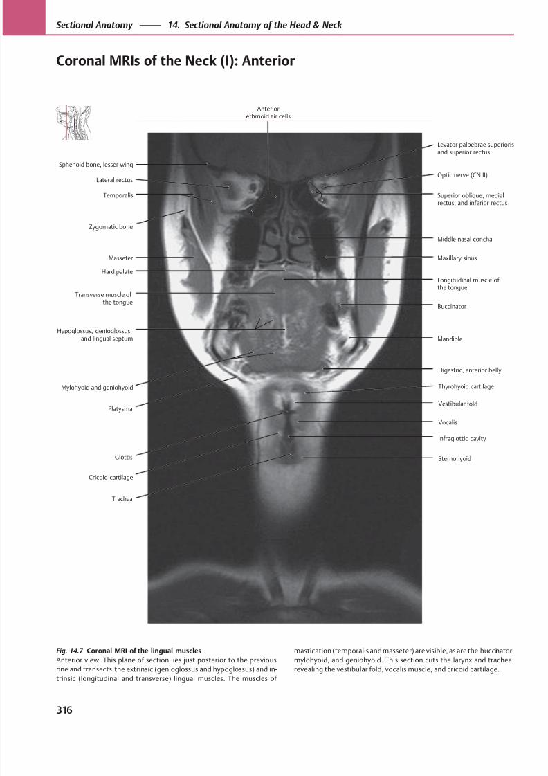
8/15/2019 Head and Neck Anatomy for Dental Medicine - Thieme; (January 26, 2010)
http://slidepdf.com/reader/full/head-and-neck-anatomy-for-dental-medicine-thieme-january-26-2010 329/384
Superior oblique, medialrectus, and inferior rectus
Temporalis
Lateral rectus
Transverse muscle ofthe tongue
Hypoglossus, genioglossus,and lingual septum
Masseter
Zygomatic bone
Glottis
Vestibular fold
Trachea
Digastric, anterior belly
Mandible
Longitudinal muscle ofthe tongue
Buccinator
Maxillary sinus
Middle nasal concha
Optic nerve (CN II)
Sphenoid bone, lesser wing
Platysma
Mylohyoid and geniohyoid
Hard palate
Thyrohyoid cartilage
Cricoid cartilage
Levator palpebrae superiorisand superior rectus
Anteriorethmoid air cells
Sternohyoid
Vocalis
Infraglottic cavity
Fig. 14.7 Coronal MRI of the lingual muscles
Anterior view. This plane of section lies just posterior to the previous
one and transects the extrinsic (genioglossus and hypoglossus) and in-
trinsic (longitudinal and transverse) lingual muscles. The muscles of
mastication (temporalis and masseter) are visible, as are the buccinator,
mylohyoid, and geniohyoid. This section cuts the larynx and trachea,
revealing the vestibular fold, vocalis muscle, and cricoid cartilage.
316
Sectional Anatomy 14. Sectional Anatomy of the Head & Neck
Coronal MRIs of the Neck (I): Anterior
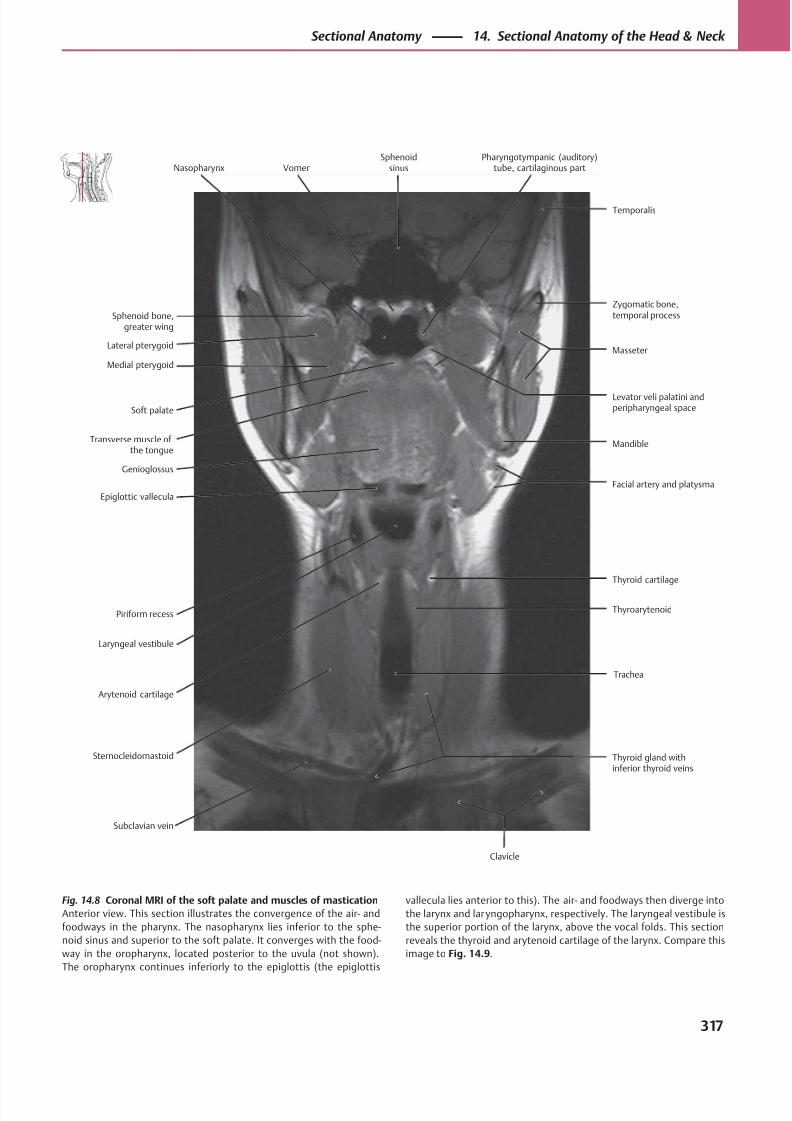
8/15/2019 Head and Neck Anatomy for Dental Medicine - Thieme; (January 26, 2010)
http://slidepdf.com/reader/full/head-and-neck-anatomy-for-dental-medicine-thieme-january-26-2010 330/384
Levator veli palatini andperipharyngeal space
Medial pterygoid
Lateral pterygoid
Epiglottic vallecula
Piriform recess
Transverse muscle ofthe tongue
Soft palate
Sternocleidomastoid
Trachea
Thyroarytenoid
Thyroid gland withinferior thyroid veins
Thyroid cartilage
Facial artery and platysma
Mandible
Masseter
Sphenoid bone,greater wing
Arytenoid cartilage
Laryngeal vestibule
Genioglossus
Subclavian vein
Zygomatic bone,temporal process
Nasopharynx VomerSphenoid
sinusPharyngotympanic (auditory)
tube, cartilaginous part
Temporalis
Clavicle
Fig. 14.8 Coronal MRI of the soft palate and muscles of mastication
Anterior view. This section illustrates the convergence of the air- and
foodways in the pharynx. The nasopharynx lies inferior to the sphe-
noid sinus and superior to the soft palate. It converges with the food-
way in the oropharynx, located posterior to the uvula (not shown).
The oropharynx continues inferiorly to the epiglottis (the epiglottis
vallecula lies anterior to this). The air- and foodways then diverge into
the larynx and laryngopharynx, respectively. The laryngeal vestibule is
the superior portion of the larynx, above the vocal folds. This section
reveals the thyroid and arytenoid cartilage of the larynx. Compare this
image to Fig. 14.9.
317
Sectional Anatomy 14. Sectional Anatomy of the Head & Neck
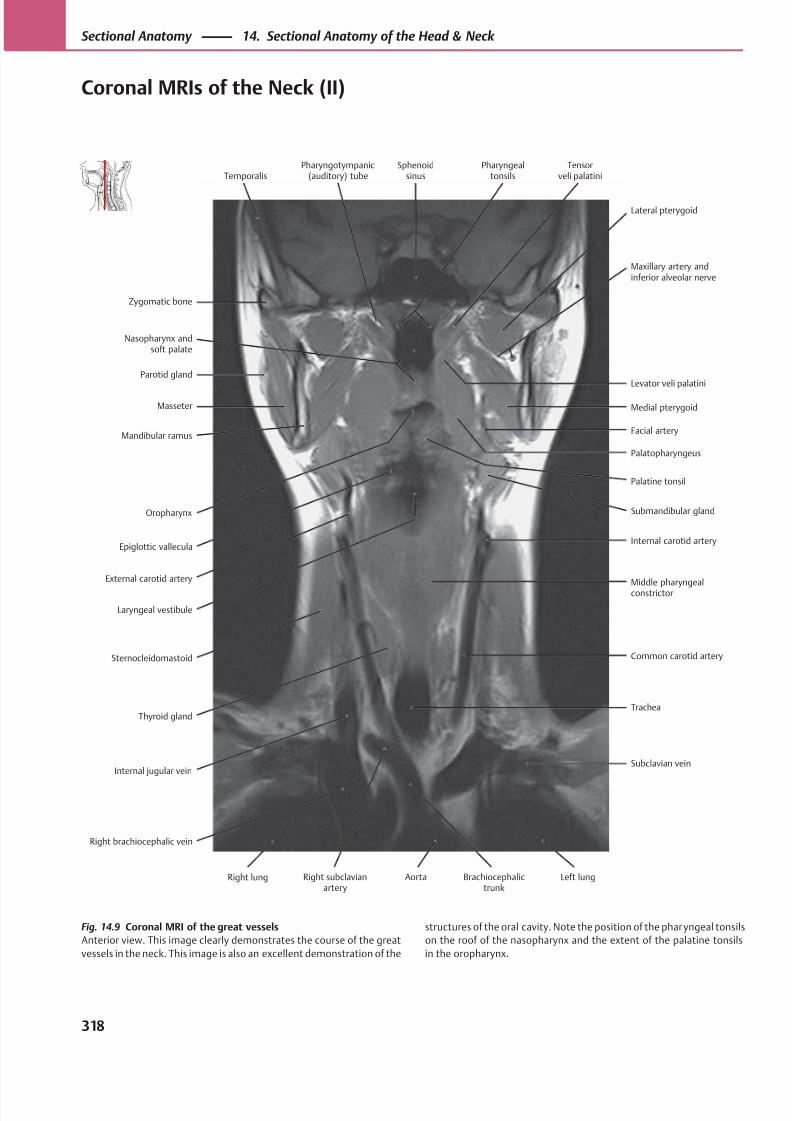
8/15/2019 Head and Neck Anatomy for Dental Medicine - Thieme; (January 26, 2010)
http://slidepdf.com/reader/full/head-and-neck-anatomy-for-dental-medicine-thieme-january-26-2010 331/384
Levator veli palatini
Nasopharynx andsoft palate
Zygomatic bone
Oropharynx
Epiglottic vallecula
Masseter
Parotid gland
Sternocleidomastoid Common carotid artery
Right brachiocephalic vein
Internal carotid artery
Submandibular gland
Palatopharyngeus
Palatine tonsil
Facial artery
Medial pterygoid
Maxillary artery andinferior alveolar nerve
Temporalis
Laryngeal vestibule
External carotid artery
Mandibular ramus
Middle pharyngealconstrictor
Thyroid gland
Lateral pterygoid
Pharyngotympanic(auditory) tube
Sphenoidsinus
Pharyngealtonsils
Tensorveli palatini
Right lung Right subclavianartery
Aorta Brachiocephalictrunk
Left lung
Internal jugular vein
Trachea
Subclavian vein
Fig. 14.9 Coronal MRI of the great vessels
Anterior view. This image clearly demonstrates the course of the great
vessels in the neck. This image is also an excellent demonstration of the
structures of the oral cavity. Note the position of the pharyngeal tonsils
on the roof of the nasopharynx and the extent of the palatine tonsils
in the oropharynx.
318
Sectional Anatomy 14. Sectional Anatomy of the Head & Neck
Coronal MRIs of the Neck (II)
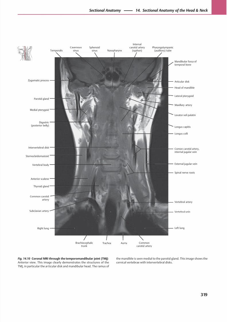
8/15/2019 Head and Neck Anatomy for Dental Medicine - Thieme; (January 26, 2010)
http://slidepdf.com/reader/full/head-and-neck-anatomy-for-dental-medicine-thieme-january-26-2010 332/384
Head of mandible
Medial pterygoid
Parotid gland
Vertebral body
Anterior scalene
Intervertebral disk
Digastric(posterior belly)
Spinal nerve roots
Comon carotid artery,internal jugular vein
Longus colli
Levator veli palatini
Longus capitis
Maxillary artery
Lateral pterygoid
Articular diskZygomatic process
Common carotidartery
Thyroid gland
Sternocleidomastoid
External jugular vein
Mandibular fossa oftemporal bone
TemporalisCavernous
sinusSphenoid
sinus Nasopharynx
Internalcarotid artery
(syphon)Pharyngotympanic
(auditory) tube
Right lung
Brachiocephalictrunk
Trachea Aorta Commoncarotid artery
Left lung
Vertebral artery
Vertebral veinSubclavian artery
Fig. 14.10 Coronal MRI through the temporomandibular joint (TMJ)
Anterior view. This image clearly demonstrates the structures of the
TMJ, in particular the articular disk and mandibular head. The ramus of
the mandible is seen medial to the parotid gland. This image shows the
cervical vertebrae with intervertebral disks.
319
Sectional Anatomy 14. Sectional Anatomy of the Head & Neck
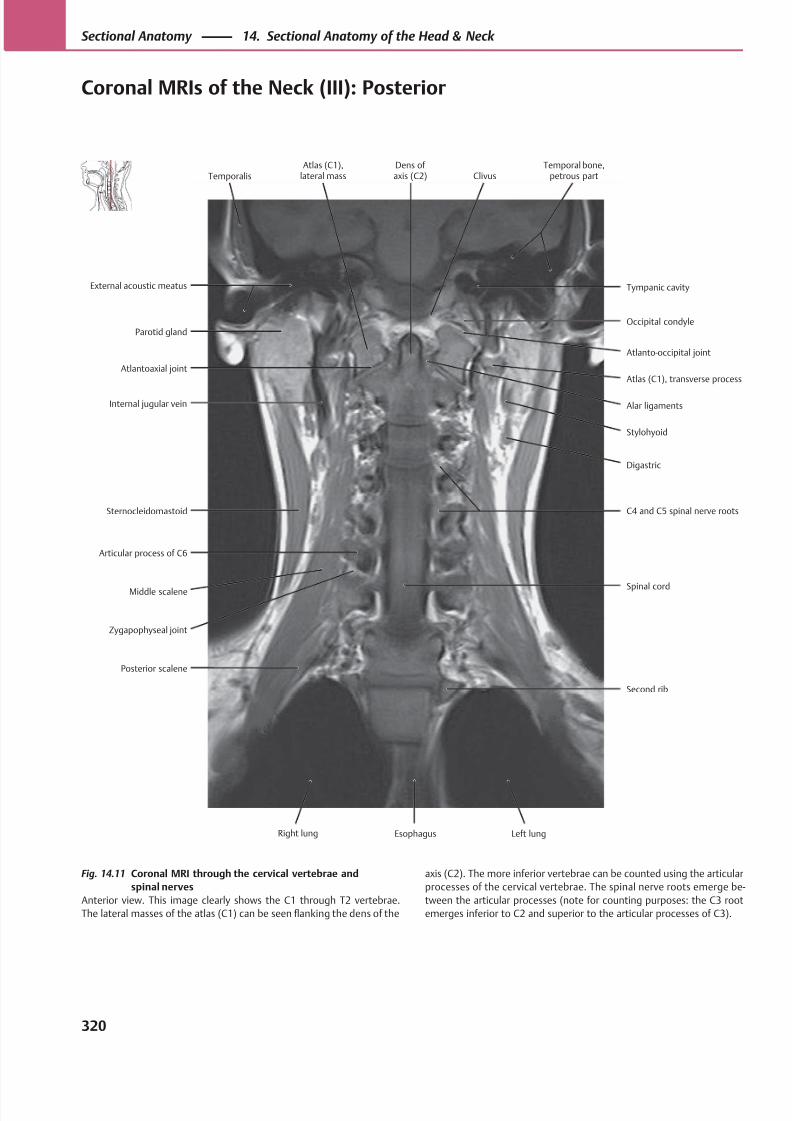
8/15/2019 Head and Neck Anatomy for Dental Medicine - Thieme; (January 26, 2010)
http://slidepdf.com/reader/full/head-and-neck-anatomy-for-dental-medicine-thieme-january-26-2010 333/384
Atlanto-occipital joint
Atlantoaxial joint
Parotid gland
Middle scalene
Zygapophyseal joint
Sternocleidomastoid
Internal jugular vein
Spinal cord
C4 and C5 spinal nerve roots
Stylohyoid
Digastric
Alar ligaments
Atlas (C1), transverse process
Occipital condyle
External acoustic meatus
Posterior scalene
Articular process of C6
Second rib
Tympanic cavity
TemporalisAtlas (C1),
lateral massDens of axis (C2) Clivus
Temporal bone,petrous part
EsophagusRight lung Left lung
Fig. 14.11 Coronal MRI through the cervical vertebrae and
spinal nerves
Anterior view. This image clearly shows the C1 through T2 vertebrae.
The lateral masses of the atlas (C1) can be seen flanking the dens of the
axis (C2). The more inferior vertebrae can be counted using the articular
processes of the cervical vertebrae. The spinal nerve roots emerge be-
tween the articular processes (note for counting purposes: the C3 root
emerges inferior to C2 and superior to the articular processes of C3).
320
Sectional Anatomy 14. Sectional Anatomy of the Head & Neck
Coronal MRIs of the Neck (III): Posterior
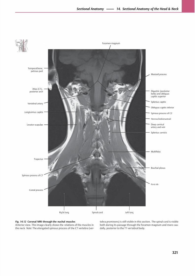
8/15/2019 Head and Neck Anatomy for Dental Medicine - Thieme; (January 26, 2010)
http://slidepdf.com/reader/full/head-and-neck-anatomy-for-dental-medicine-thieme-january-26-2010 334/384
Splenius capitisVertebral artery
Atlas (C1),posterior arch
Spinous process of C7
Costal process
Levator scapulae
Longissimus capitis
First rib
Multifidus
Splenius cervicis
Sternocleidomastoid
Deep cervicalartery and vein
Spinous process of C2
Obliquus capitis inferior
Digastric (posteriorbelly) and obliquus
capitis superior
Temporal bone,petrous part
Trapezius
Brachial plexus
Mastoid process
Foramen magnum
Right lung Spinal cord Left lung
Fig. 14.12 Coronal MRI through the nuchal muscles
Anterior view. This image clearly shows the relations of the muscles in
the neck. Note: The elongated spinous process of the C7 vertebra (ver-
tebra prominens) is still visible in this section. The spinal cord is visible
both during its passage through the foramen magnum and more cau-
dally, posterior to the T1 vertebral body.
321
Sectional Anatomy 14. Sectional Anatomy of the Head & Neck
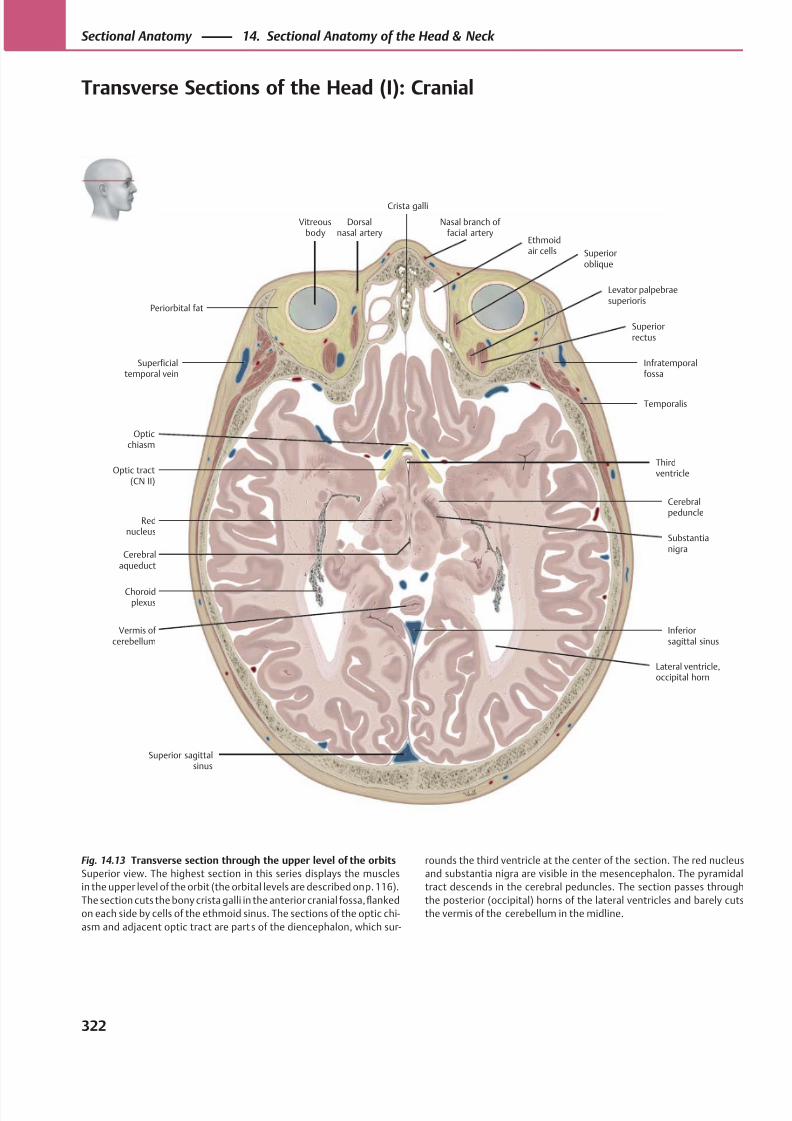
8/15/2019 Head and Neck Anatomy for Dental Medicine - Thieme; (January 26, 2010)
http://slidepdf.com/reader/full/head-and-neck-anatomy-for-dental-medicine-thieme-january-26-2010 335/384
Superficialtemporal vein
Temporalis
Superior sagittalsinus
Rednucleus
Substantianigra
Cerebralpeduncle
Optic tract(CN II)
Thirdventricle
Opticchiasm
Infratemporalfossa
Vitreousbody
Superioroblique
Ethmoidair cells
Crista galli
Levator palpebraesuperioris
Superiorrectus
Periorbital fat
Vermis of cerebellum
Lateral ventricle,occipital horn
Choroidplexus
Inferiorsagittal sinus
Cerebralaqueduct
Dorsalnasal artery
Nasal branch of facial artery
Fig. 14.13 Transverse section through the upper level of the orbits
Superior view. The highest section in this series displays the muscles
in the upper level of the orbit (the orbital levels are described on p. 116).
The section cuts the bony crista galli in the anterior cranial fossa, flanked
on each side by cells of the ethmoid sinus. The sections of the optic chi-
asm and adjacent optic tract are parts of the diencephalon, which sur-
rounds the third ventricle at the center of the section. The red nucleus
and substantia nigra are visible in the mesencephalon. The pyramidal
tract descends in the cerebral peduncles. The section passes through
the posterior (occipital) horns of the lateral ventricles and barely cuts
the vermis of the cerebellum in the midline.
322
Sectional Anatomy 14. Sectional Anatomy of the Head & Neck
Transverse Sections of the Head (I): Cranial
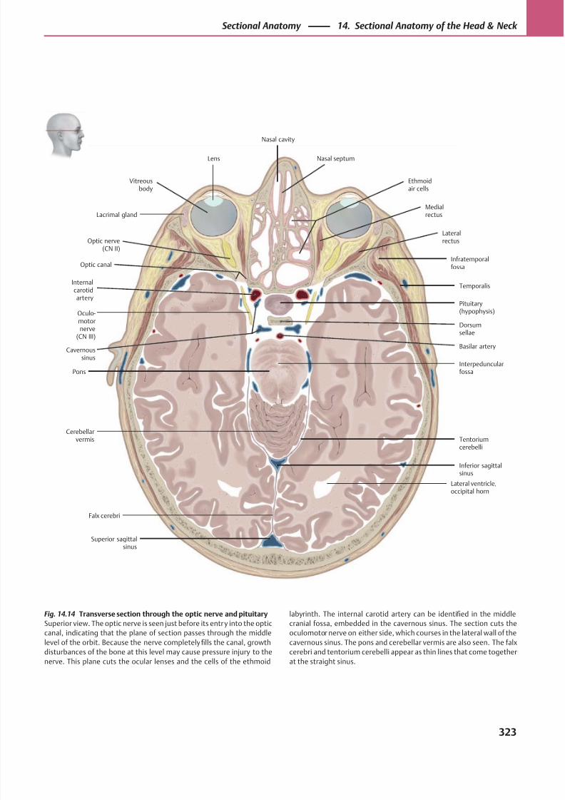
8/15/2019 Head and Neck Anatomy for Dental Medicine - Thieme; (January 26, 2010)
http://slidepdf.com/reader/full/head-and-neck-anatomy-for-dental-medicine-thieme-january-26-2010 336/384
Dorsumsellae
Optic nerve(CN II)
Inferior sagittalsinus
Superior sagittalsinus
Falx cerebri
Cerebellarvermis
PonsInterpeduncularfossa
Basilar artery
Internalcarotidartery
Lateralrectus
Lacrimal glandMedialrectus
Vitreousbody
Lens
Ethmoidair cells
Nasal cavity
Nasal septum
Tentoriumcerebelli
Infratemporalfossa
Lateral ventricle,occipital horn
Pituitary(hypophysis)
Optic canal
Oculo-motornerve
(CN III)
Temporalis
Cavernoussinus
Fig. 14.14 Transverse section through the optic nerve and pituitary
Superior view. The optic nerve is seen just before its entry into the optic
canal, indicating that the plane of section passes through the middle
level of the orbit. Because the nerve completely fills the canal, growth
disturbances of the bone at this level may cause pressure injury to the
nerve. This plane cuts the ocular lenses and the cells of the ethmoid
labyrinth. The internal carotid artery can be identified in the middle
cranial fossa, embedded in the cavernous sinus. The section cuts the
oculomotor nerve on either side, which courses in the lateral wall of the
cavernous sinus. The pons and cerebellar vermis are also seen. The falx
cerebri and tentorium cerebelli appear as thin lines that come together
at the straight sinus.
323
Sectional Anatomy 14. Sectional Anatomy of the Head & Neck
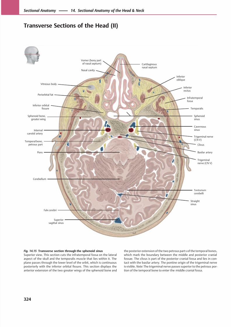
8/15/2019 Head and Neck Anatomy for Dental Medicine - Thieme; (January 26, 2010)
http://slidepdf.com/reader/full/head-and-neck-anatomy-for-dental-medicine-thieme-january-26-2010 337/384
Straightsinus
Superiorsagittal sinus
Falx cerebri
Tentoriumcerebelli
Pons
Temporal bone,petrous part
Internalcarotid artery
Nasal cavity
Vomer (bony partof nasal septum) Cartilaginous
nasal septum
Cavernoussinus
Temporalis
Infratemporalfossa
Inferiorrectus
Sphenoidsinus
Inferioroblique
Clivus
Basilar artery
Trigeminal nerve(CN V)
Cerebellum
Vitreous body
Inferior orbitalfissure
Sphenoid bone,greater wing
Periorbital fat
Trigeminalnerve (CN V)
Fig. 14.15 Transverse section through the sphenoid sinus
Superior view. This section cuts the infratemporal fossa on the lateral
aspect of the skull and the temporalis muscle that lies within it. The
plane passes through the lower level of the orbit, which is continuous
posteriorly with the inferior orbital fissure. This section displays the
anterior extension of the two greater wings of the sphenoid bone and
the posterior extension of the two petrous parts of the temporal bones,
which mark the boundary between the middle and posterior cranial
fossae. The clivus is part of the posterior cranial fossa and lies in con-
tact with the basilar artery. The pontine origin of the trigeminal nerve
is visible. Note: The trigeminal nerve passes superior to the petrous por-
tion of the temporal bone to enter the middle cranial fossa.
324
Sectional Anatomy 14. Sectional Anatomy of the Head & Neck
Transverse Sections of the Head (II)
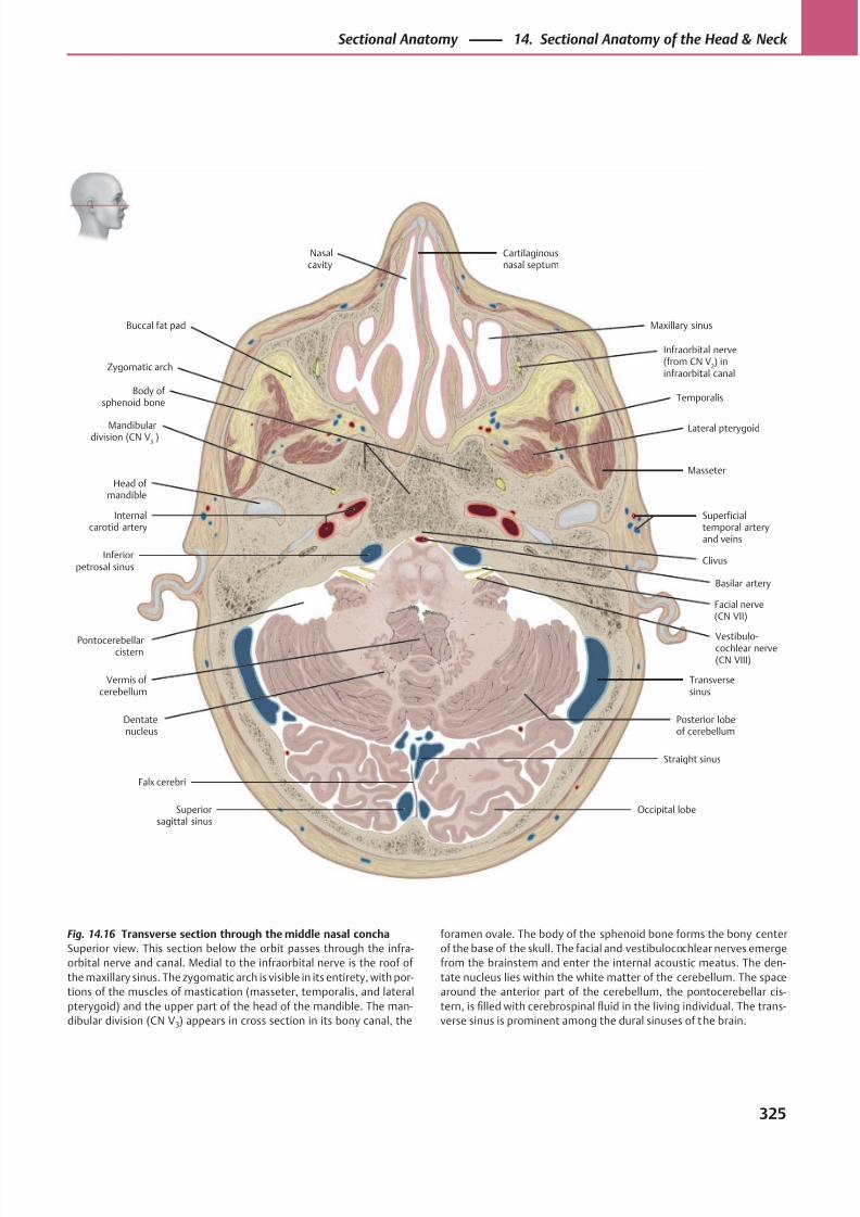
8/15/2019 Head and Neck Anatomy for Dental Medicine - Thieme; (January 26, 2010)
http://slidepdf.com/reader/full/head-and-neck-anatomy-for-dental-medicine-thieme-january-26-2010 338/384
Pontocerebellarcistern
Zygomatic arch
Body of sphenoid bone
Clivus
Basilar artery
Vermis of cerebellum
Dentatenucleus
Superiorsagittal sinus
Occipital lobe
Vestibulo-cochlear nerve(CN VIII)
Inferiorpetrosal sinus
Superficialtemporal arteryand veins
Temporalis
Buccal fat pad
Infraorbital nerve(from CN V
2) in
infraorbital canal
Maxillary sinus
Falx cerebri
Facial nerve(CN VII)
Internalcarotid artery
Mandibulardivision (CN V
3 )
Lateral pterygoid
Nasalcavity
Cartilaginousnasal septum
Head of mandible
Posterior lobeof cerebellum
Transversesinus
Straight sinus
Masseter
Fig. 14.16 Transverse section through the middle nasal concha
Superior view. This section below the orbit passes through the infra-
orbital nerve and canal. Medial to the infraorbital nerve is the roof of
the maxillary sinus. The zygomatic arch is visible in its entirety, with por-
tions of the muscles of mastication (masseter, temporalis, and lateral
pterygoid) and the upper part of the head of the mandible. The man-
dibular division (CN V3) appears in cross section in its bony canal, the
foramen ovale. The body of the sphenoid bone forms the bony center
of the base of the skull. The facial and vestibulocochlear nerves emerge
from the brainstem and enter the internal acoustic meatus. The den-
tate nucleus lies within the white matter of the cerebellum. The space
around the anterior part of the cerebellum, the pontocerebellar cis-
tern, is filled with cerebrospinal fluid in the living individual. The trans-
verse sinus is prominent among the dural sinuses of the brain.
325
Sectional Anatomy 14. Sectional Anatomy of the Head & Neck
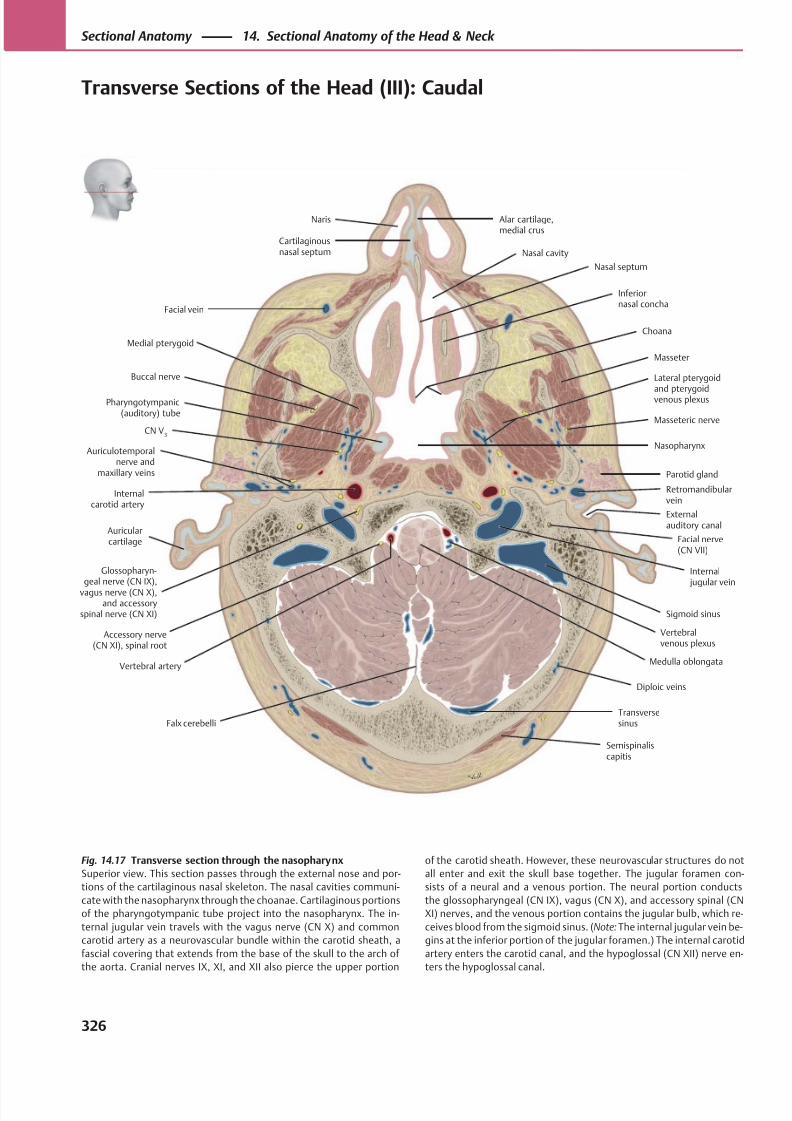
8/15/2019 Head and Neck Anatomy for Dental Medicine - Thieme; (January 26, 2010)
http://slidepdf.com/reader/full/head-and-neck-anatomy-for-dental-medicine-thieme-january-26-2010 339/384
Facial vein
Transversesinus
Masseter
Lateral pterygoid
and pterygoidvenous plexus
Parotid gland
Facial nerve(CN VII)
Glossopharyn-geal nerve (CN IX),
vagus nerve (CN X),and accessory
spinal nerve (CN XI)
Accessory nerve(CN XI), spinal root
Medulla oblongata
Semispinaliscapitis
Falx cerebelli
Vertebral artery
Sigmoid sinus
Auricularcartilage
Externalauditory canal
Internal jugular vein
Auriculotemporalnerve and
maxillary veins
Internalcarotid artery
CN V3
Masseteric nerve
Buccal nerve
Pharyngotympanic(auditory) tube
Nasopharynx
Choana
Medial pterygoid
Inferiornasal concha
Naris
Cartilaginousnasal septum
Alar cartilage,medial crus
Nasal septum
Nasal cavity
Diploic veins
Vertebralvenous plexus
Retromandibularvein
Fig. 14.17 Transverse section through the nasopharynx
Superior view. This section passes through the external nose and por-
tions of the cartilaginous nasal skeleton. The nasal cavities communi-
cate with the nasopharynx through the choanae. Cartilaginous portions
of the pharyngotympanic tube project into the nasopharynx. The in-
ternal jugular vein travels with the vagus nerve (CN X) and common
carotid artery as a neurovascular bundle within the carotid sheath, a
fascial covering that extends from the base of the skull to the arch of
the aorta. Cranial nerves IX, XI, and XII also pierce the upper portion
of the carotid sheath. However, these neurovascular structures do not
all enter and exit the skull base together. The jugular foramen con-
sists of a neural and a venous portion. The neural portion conducts
the glossopharyngeal (CN IX), vagus (CN X), and accessory spinal (CN
XI) nerves, and the venous portion contains the jugular bulb, which re-
ceives blood from the sigmoid sinus. (Note: The internal jugular vein be-
gins at the inferior portion of the jugular foramen.) The internal carotid
artery enters the carotid canal, and the hypoglossal (CN XII) nerve en-
ters the hypoglossal canal.
326
Sectional Anatomy 14. Sectional Anatomy of the Head & Neck
Transverse Sections of the Head (III): Caudal
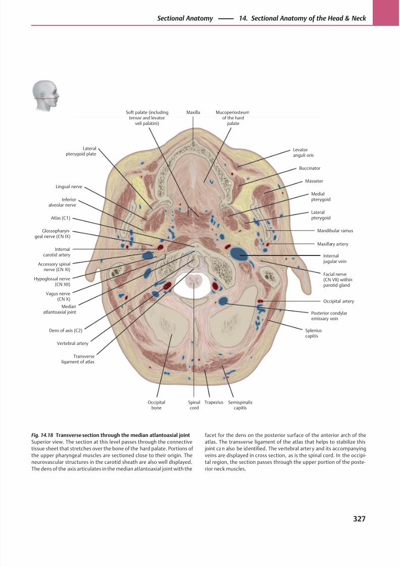
8/15/2019 Head and Neck Anatomy for Dental Medicine - Thieme; (January 26, 2010)
http://slidepdf.com/reader/full/head-and-neck-anatomy-for-dental-medicine-thieme-january-26-2010 340/384
Trapezius
Glossopharyn-geal nerve (CN IX)
Dens of axis (C2)
Soft palate (includingtensor and levator
veli palatini)
Atlas (C1)
Internalcarotid artery
Facial nerve(CN VII) withinparotid gland
Accessory spinalnerve (CN XI)
Hypoglossal nerve(CN XII)
Vagus nerve
(CN X)
Medianatlantoaxial joint
Transverseligament of atlas
Occipitalbone
Spinalcord
Posterior condylaremissary vein
Semispinaliscapitis
Vertebral artery
Spleniuscapitis
Occipital artery
Internal jugular vein
Maxillary artery
Inferioralveolar nerve
Lateralpterygoid
Mandibular ramus
Lingual nerveMasseter
Medial
pterygoid
Buccinator
Levatoranguli oris
Mucoperiosteumof the hard
palate
Maxilla
Lateralpterygoid plate
Fig. 14.18 Transverse section through the median atlantoaxial joint
Superior view. The section at this level passes through the connective
tissue sheet that stretches over the bone of the hard palate. Portions of
the upper pharyngeal muscles are sectioned close to their origin. The
neurovascular structures in the carotid sheath are also well displayed.
The dens of the axis articulates in the median atlantoaxial joint with the
facet for the dens on the posterior surface of the anterior arch of the
atlas. The transverse ligament of the atlas that helps to stabilize this
joint can also be identified. The vertebral arter y and its accompanying
veins are displayed in cross section, as is the spinal cord. In the occipi-
tal region, the section passes through the upper portion of the poste-
rior neck muscles.
327
Sectional Anatomy 14. Sectional Anatomy of the Head & Neck
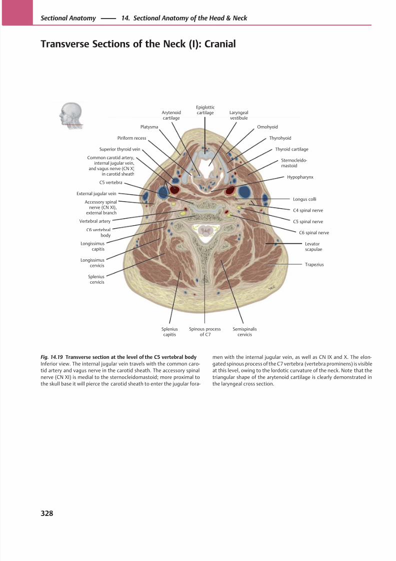
8/15/2019 Head and Neck Anatomy for Dental Medicine - Thieme; (January 26, 2010)
http://slidepdf.com/reader/full/head-and-neck-anatomy-for-dental-medicine-thieme-january-26-2010 341/384
OmohyoidPlatysma
Superior thyroid vein
External jugular vein
Accessory spinalnerve (CN XI),
external branch
Common carotid artery,internal jugular vein,
and vagus nerve (CN X)in carotid sheath
Longissimuscapitis
Longissimuscervicis
Levatorscapulae
Trapezius
Spleniuscervicis
Spleniuscapitis
Semispinaliscervicis
C6 spinal nerve
Vertebral artery C5 spinal nerve
C4 spinal nerve
Sternocleido-mastoid
Piriform recess
Thyroid cartilage
Laryngealvestibule
Epiglotticcartilage
Longus colli
Thyrohyoid
Arytenoidcartilage
HypopharynxC5 vertebra
C6 vertebralbody
Spinous processof C7
Fig. 14.19 Transverse section at the level of the C5 vertebral body
Inferior view. The internal jugular vein travels with the common caro-
tid artery and vagus nerve in the carotid sheath. The accessory spinal
nerve (CN XI) is medial to the sternocleidomastoid; more proximal to
the skull base it will pierce the carotid sheath to enter the jugular fora-
men with the internal jugular vein, as well as CN IX and X. The elon-
gated spinous process of the C7 vertebra (vertebra prominens) is visible
at this level, owing to the lordotic curvature of the neck. Note that the
triangular shape of the arytenoid cartilage is clearly demonstrated in
the laryngeal cross section.
328
Sectional Anatomy 14. Sectional Anatomy of the Head & Neck
Transverse Sections of the Neck (I): Cranial
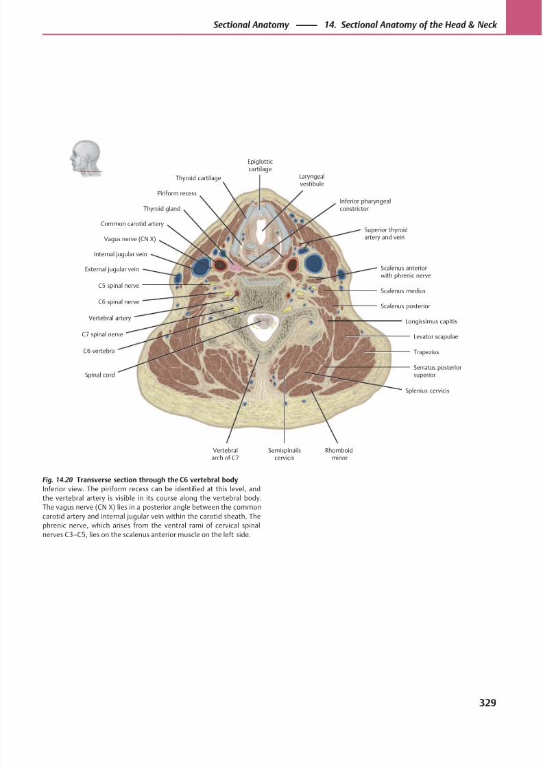
8/15/2019 Head and Neck Anatomy for Dental Medicine - Thieme; (January 26, 2010)
http://slidepdf.com/reader/full/head-and-neck-anatomy-for-dental-medicine-thieme-january-26-2010 342/384
Thyroid gland
Superior thyroidartery and vein
C5 spinal nerve
C6 spinal nerve
C7 spinal nerve
Spinal cord
Semispinaliscervicis
Rhomboidminor
Splenius cervicis
Serratus posteriorsuperior
Trapezius
Levator scapulae
Longissimus capitis
Scalenus posterior
Scalenus medius
Scalenus anteriorwith phrenic nerve
Vertebral artery
C6 vertebra
Piriform recess
Thyroid cartilage Laryngealvestibule
Epiglotticcartilage
Common carotid artery
Internal jugular vein
External jugular vein
Vagus nerve (CN X)
Inferior pharyngealconstrictor
Vertebralarch of C7
Fig. 14.20 Transverse section through the C6 vertebral body
Inferior view. The piriform recess can be identified at this level, and
the vertebral artery is visible in its course along the vertebral body.
The vagus nerve (CN X) lies in a posterior angle between the common
carotid artery and internal jugular vein within the carotid sheath. The
phrenic nerve, which arises from the ventral rami of cervical spinal
nerves C3–C5, lies on the scalenus anterior muscle on the left side.
329
Sectional Anatomy 14. Sectional Anatomy of the Head & Neck
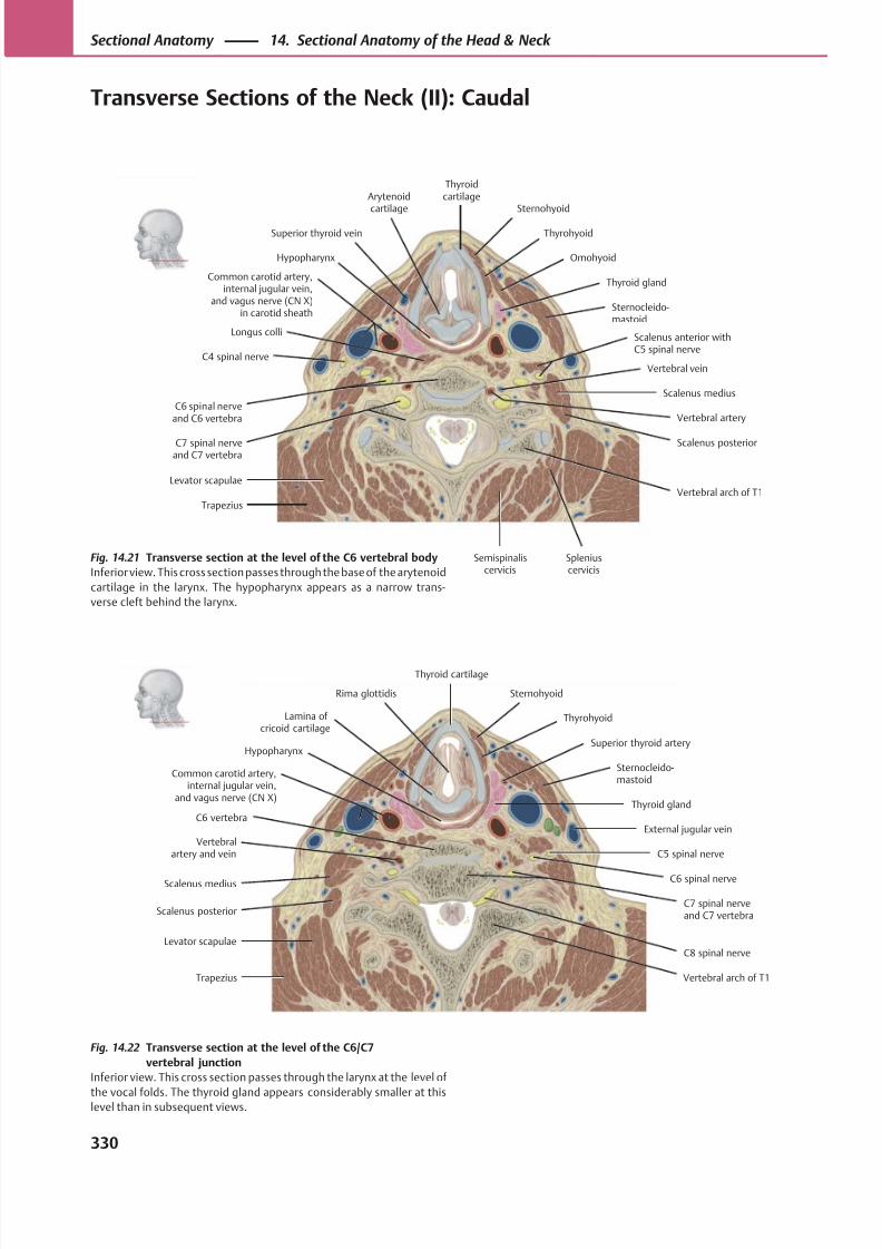
8/15/2019 Head and Neck Anatomy for Dental Medicine - Thieme; (January 26, 2010)
http://slidepdf.com/reader/full/head-and-neck-anatomy-for-dental-medicine-thieme-january-26-2010 343/384
Hypopharynx
Lamina ofcricoid cartilage
Superior thyroid artery
Common carotid artery,internal jugular vein,
and vagus nerve (CN X)
External jugular vein
C5 spinal nerve
Scalenus medius C6 spinal nerve
Scalenus posteriorC7 spinal nerveand C7 vertebra
Levator scapulaeC8 spinal nerve
Vertebralartery and vein
Thyroid gland
Sternocleido-mastoid
Thyrohyoid
SternohyoidRima glottidis
Thyroid cartilage
C6 vertebra
Vertebral arch of T1Trapezius
Sternohyoid
ThyrohyoidSuperior thyroid vein
Thyroid gland
Longus colli
C4 spinal nerve
C6 spinal nerveand C6 vertebra
C7 spinal nerveand C7 vertebra
Hypopharynx
Semispinaliscervicis
Spleniuscervicis
Scalenus posterior
Scalenus medius
Vertebral vein
Vertebral artery
Scalenus anterior withC5 spinal nerve
Common carotid artery,internal jugular vein,
and vagus nerve (CN X)in carotid sheath
Sternocleido-mastoid
Arytenoidcartilage
Omohyoid
Thyroidcartilage
Trapezius
Levator scapulaeVertebral arch of T1
Fig. 14.21 Transverse section at the level of the C6 vertebral body
Inferior view. This cross section passes through the base of the arytenoid
cartilage in the larynx. The hypopharynx appears as a narrow trans-
verse cleft behind the larynx.
Fig. 14.22 Transverse section at the level of the C6/C7
vertebral junction
Inferior view. This cross section passes through the larynx at the level of
the vocal folds. The thyroid gland appears considerably smaller at thislevel than in subsequent views.
330
Sectional Anatomy 14. Sectional Anatomy of the Head & Neck
Transverse Sections of the Neck (II): Caudal
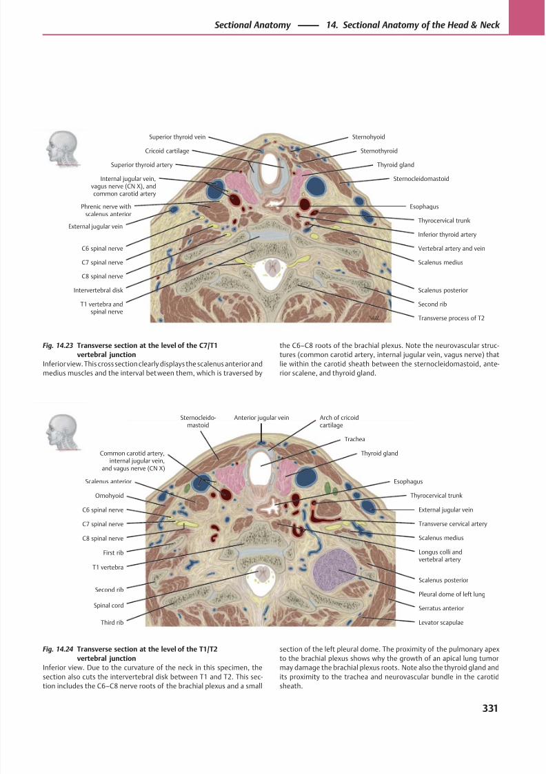
8/15/2019 Head and Neck Anatomy for Dental Medicine - Thieme; (January 26, 2010)
http://slidepdf.com/reader/full/head-and-neck-anatomy-for-dental-medicine-thieme-january-26-2010 344/384
First rib
Second rib
Sternocleido-mastoid
Omohyoid
C6 spinal nerve
C7 spinal nerve
C8 spinal nerve
T1 vertebra
Third rib
Spinal cord
Levator scapulae
Serratus anterior
Pleural dome of left lung
Scalenus posterior
Scalenus medius
External jugular vein
Transverse cervical artery
Scalenus anterior
Thyrocervical trunk
Esophagus
Thyroid gland
Trachea
Anterior jugular vein
Common carotid artery,internal jugular vein,
and vagus nerve (CN X)
Arch of cricoidcartilage
Longus colli andvertebral artery
Superior thyroid vein
Superior thyroid artery Thyroid gland
SternocleidomastoidInternal jugular vein,vagus nerve (CN X), andcommon carotid artery
External jugular vein
C6 spinal nerve
C7 spinal nerve
C8 spinal nerve
Intervertebral disk
T1 vertebra andspinal nerve
Vertebral artery and vein
Second rib
Scalenus posterior
Scalenus medius
Esophagus
Thyrocervical trunk
Sternothyroid
Sternohyoid
Transverse process of T2
Phrenic nerve withscalenus anterior
Inferior thyroid artery
Cricoid cartilage
Fig. 14.24 Transverse section at the level of the T1/T2
vertebral junction
Inferior view. Due to the curvature of the neck in this specimen, the
section also cuts the intervertebral disk between T1 and T2. This sec-tion includes the C6–C8 nerve roots of the brachial plexus and a small
Fig. 14.23 Transverse section at the level of the C7/T1
vertebral junction
Inferior view. This cross section clearly displays the scalenus anterior and
medius muscles and the interval between them, which is traversed by
section of the left pleural dome. The proximity of the pulmonary apex
to the brachial plexus shows why the growth of an apical lung tumor
may damage the brachial plexus roots. Note also the thyroid gland and
its proximity to the trachea and neurovascular bundle in the carotidsheath.
the C6–C8 roots of the brachial plexus. Note the neurovascular struc-
tures (common carotid artery, internal jugular vein, vagus nerve) that
lie within the carotid sheath between the sternocleidomastoid, ante-
rior scalene, and thyroid gland.
331
Sectional Anatomy 14. Sectional Anatomy of the Head & Neck
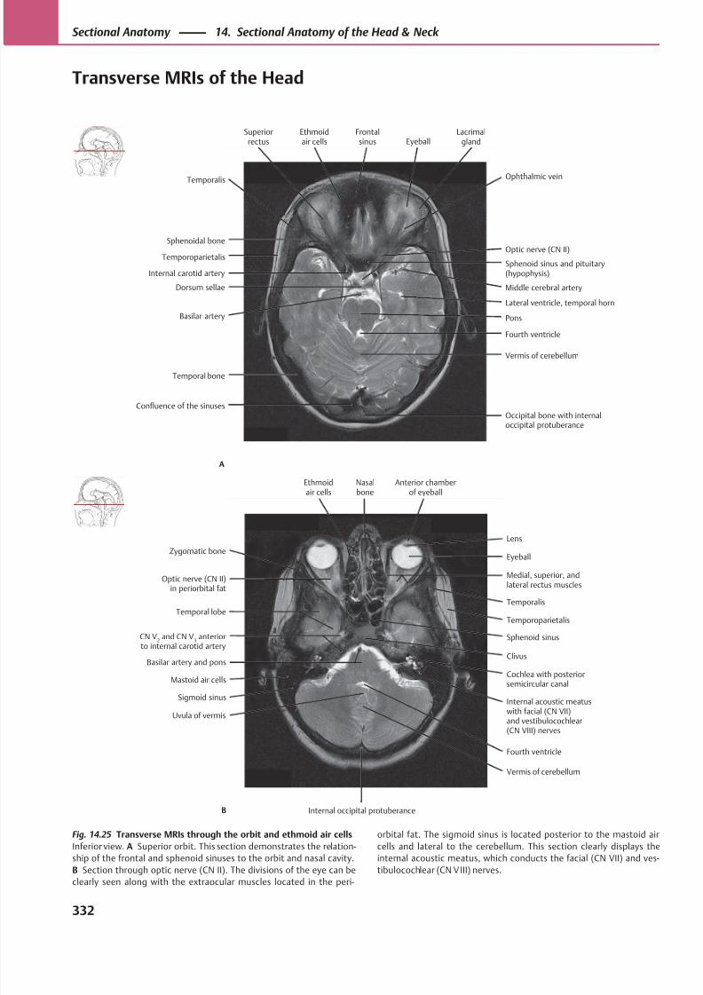
8/15/2019 Head and Neck Anatomy for Dental Medicine - Thieme; (January 26, 2010)
http://slidepdf.com/reader/full/head-and-neck-anatomy-for-dental-medicine-thieme-january-26-2010 345/384
Sphenoid sinus and pituitary(hypophysis)
Temporoparietalis
Sphenoidal bone
Temporal bone
Confluence of the sinuses
Dorsum sellae
Internal carotid artery
Occipital bone with internaloccipital protuberance
Vermis of cerebellum
Pons
Fourth ventricle
Lateral ventricle, temporal horn
Middle cerebral artery
Optic nerve (CN II)
Temporalis
Basilar artery
Ophthalmic vein
Superiorrectus
Ethmoidair cells
Frontalsinus Eyeball
Lacrimalgland
A
Medial, superior, andlateral rectus muscles
Temporal lobe
Optic nerve (CN II)in periorbital fat
Sigmoid sinus
Uvula of vermis
Basilar artery and pons
CN V2 and CN V
3 anterior
to internal carotid artery
Vermis of cerebellum
Internal acoustic meatuswith facial (CN VII)and vestibulocochlear(CN VIII) nerves
Cochlea with posteriorsemicircular canal
Sphenoid sinus
Clivus
Temporoparietalis
Temporalis
EyeballZygomatic bone
Mastoid air cells
Fourth ventricle
Lens
Ethmoidair cells
Nasalbone
Anterior chamberof eyeball
B Internal occipital protuberance
Fig. 14.25 Transverse MRIs through the orbit and ethmoid air cells
Inferior view. A Superior orbit. This section demonstrates the relation-
ship of the frontal and sphenoid sinuses to the orbit and nasal cavity.
B Section through optic nerve (CN II). The divisions of the eye can beclearly seen along with the extraocular muscles located in the peri-
orbital fat. The sigmoid sinus is located posterior to the mastoid air
cells and lateral to the cerebellum. This section clearly displays the
internal acoustic meatus, which conducts the facial (CN VII) and ves-
tibulocochlear (CN VIII) nerves.
332
Sectional Anatomy 14. Sectional Anatomy of the Head & Neck
Transverse MRIs of the Head
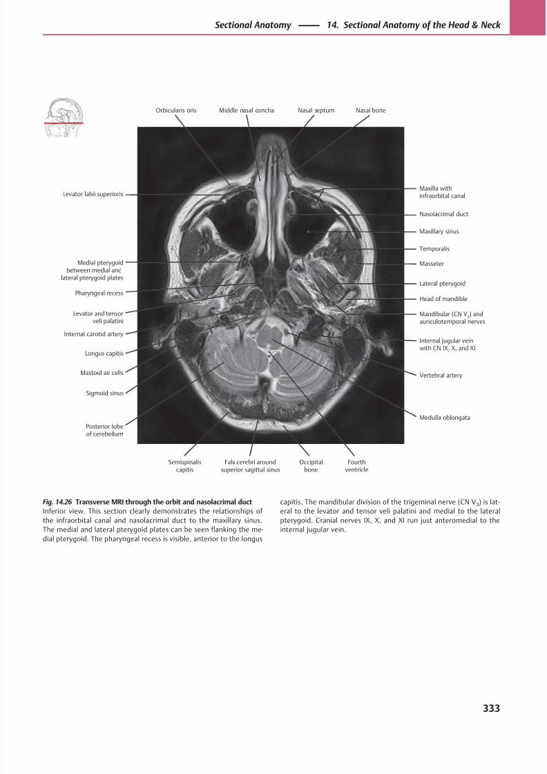
8/15/2019 Head and Neck Anatomy for Dental Medicine - Thieme; (January 26, 2010)
http://slidepdf.com/reader/full/head-and-neck-anatomy-for-dental-medicine-thieme-january-26-2010 346/384
Temporalis
Medial pterygoid
between medial andlateral pterygoid plates
Levator labii superioris
Longus capitis
Mastoid air cells
Levator and tensorveli palatini
Pharyngeal recess
Maxilla withinfraorbital canal
Vertebral artery
Internal jugular veinwith CN IX, X, and XI
Head of mandible
Mandibular (CN V3) and
auriculotemporal nerves
Lateral pterygoid
Masseter
Maxillary sinus
Orbicularis oris
Posterior lobeof cerebellum
Sigmoid sinus
Internal carotid artery
Medulla oblongata
Nasolacrimal duct
Middle nasal concha Nasal septum Nasal bone
Semispinaliscapitis
Falx cerebri aroundsuperior sagittal sinus
Occipitalbone
Fourthventricle
Fig. 14.26 Transverse MRI through the orbit and nasolacrimal duct
Inferior view. This section clearly demonstrates the relationships of
the infraorbital canal and nasolacrimal duct to the maxillary sinus.
The medial and lateral pterygoid plates can be seen flanking the me-
dial pterygoid. The pharyngeal recess is visible, anterior to the longus
capitis. The mandibular division of the trigeminal nerve (CN V 3) is lat-
eral to the levator and tensor veli palatini and medial to the lateral
pterygoid. Cranial nerves IX, X, and XI run just anteromedial to the
internal jugular vein.
333
Sectional Anatomy 14. Sectional Anatomy of the Head & Neck
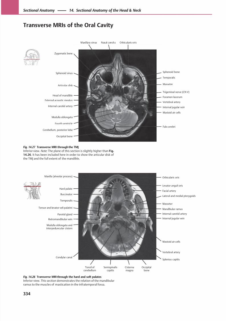
8/15/2019 Head and Neck Anatomy for Dental Medicine - Thieme; (January 26, 2010)
http://slidepdf.com/reader/full/head-and-neck-anatomy-for-dental-medicine-thieme-january-26-2010 347/384
MasseterArticular disk
Sphenoid sinus
Medulla oblongata
External acoustic meatus
Head of mandible
Internal jugular vein
Vertebral artery
Mastoid air cells
Foramen lacerum
Trigeminal nerve (CN V)
Temporalis
Zygomatic bone
Internal carotid artery
Sphenoid bone
Cerebellum, posterior lobe
Fourth ventricle
Occipital bone
Falx cerebri
Maxillary sinus Nasal concha Orbicularis oris
Facial arteryHard palate
Maxilla (alveolar process)
Parotid gland
Retromandibular vein
Temporalis
Buccinator
Splenius capitis
Mastoid air cells
Internal jugular vein
Mandibular ramus
Internal carotid artery
Masseter
Lateral and medial pterygoids
Levator anguli oris
Tonsil of cerebellum
Condylar canal
Medulla oblongata andinterpeduncular cistern
Tensor and levator veli palatini
Vertebral artery
Orbicularis oris
Semispinaliscapitis
Cisternamagna
Occipitalbone
Fig. 14.28 Transverse MRI through the hard and soft palates
Inferior view. This section demonstrates the relation of the mandibularramus to the muscles of mastication in the infratemporal fossa.
Fig. 14.27 Transverse MRI through the TMJ
Inferior view. Note: The plane of this section is slightly higher than Fig.
14.26. It has been included here in order to show the articular disk of
the TMJ and the full extent of the mandible.
334
Sectional Anatomy 14. Sectional Anatomy of the Head & Neck
Transverse MRIs of the Oral Cavity
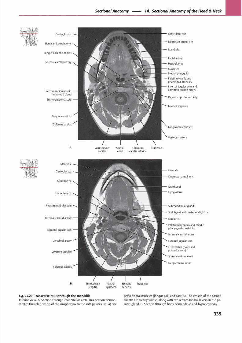
8/15/2019 Head and Neck Anatomy for Dental Medicine - Thieme; (January 26, 2010)
http://slidepdf.com/reader/full/head-and-neck-anatomy-for-dental-medicine-thieme-january-26-2010 348/384
HypoglossusExternal carotid artery
Longus colli and capitis
Splenius capitis
Sternocleidomastoid
Retromandibular veinin parotid gland
Vertebral artery
Levator scapulae
Digastric, posterior belly
Palatine tonsils andpharyngeal muscles
Internal jugular vein andcommon carotid artery
Medial pterygoid
Masseter
Facial artery
Uvula and oropharynx
Body of axis (C2)
Longissimus cervicis
Mandible
Genioglossus Orbicularis oris
Depressor anguli oris
Semispinaliscapitis
Spinalcord
Obliquuscapitis inferior
TrapeziusA
Mylohyoid
Oropharynx
Genioglossus
External jugular vein
Vertebral artery
Retromandibular vein
Hypopharynx
C3 vertebra (body andposterior arch)
Internal carotid artery
Palatopharyngeus and middlepharyngeal constrictor
Stylohyoid and posterior digastric
Epiglottis
Submandibular gland
Hyoglossus
Depressor anguli oris
Mandible
Splenius capitis
Levator scapulae
External carotid artery
External jugular vein
Mentalis
Semispinaliscapitis
Nuchalligament
Spinaliscervicis
TrapeziusB
Deep cervical veins
Sternocleidomastoid
Fig. 14.29 Transverse MRIs through the mandible
Inferior view. A Section through mandibular arch. This section demon-strates the relationship of the oropharynx to the soft palate (uvula) and
prevertebral muscles (longus colli and capitis). The vessels of the carotid
sheath are clearly visible, along with the retromandibular vein in the pa-rotid gland. B Section through body of mandible and hypophyarynx.
335
Sectional Anatomy 14. Sectional Anatomy of the Head & Neck
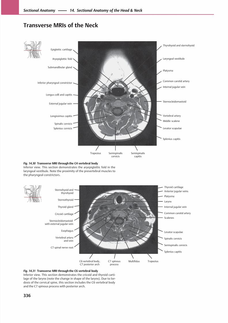
8/15/2019 Head and Neck Anatomy for Dental Medicine - Thieme; (January 26, 2010)
http://slidepdf.com/reader/full/head-and-neck-anatomy-for-dental-medicine-thieme-january-26-2010 349/384
Platysma
Aryepiglottic fold
Epiglottic cartilage
External jugular vein
Longissimus capitis
Inferior pharyngeal constrictor
Submandibular gland
Levator scapulae
Middle scalene
Sternocleidomastoid
Vertebral artery
Internal jugular vein
Common carotid artery
Laryngeal vestibule
Trapezius
Splenius cervicis
Spinalis cervicis
Longus colli and capitis
Splenius capitis
Thyrohyoid and sternohyoid
Semispinaliscervicis
Semispinaliscapitis
Platysma
Thyroid gland
Sternothyroid
Vertebral arteryand vein
C7 spinal nerve root
Sternocleidomastoidwith external jugular vein
Cricoid cartilage
Splenius capitis
Spinalis cervicis
Levator scapulae
Common carotid artery
Scalenes
Internal jugular vein
Larynx
Anterior jugular veinsSternohyoid and
thyrohyoid
Esophagus
Semispinalis cervicis
Thyroid cartilage
C6 vertebral body,C7 posterior arch
C7 spinousprocess
Multifidus Trapezius
Fig. 14.31 Transverse MRI through the C6 vertebral body
Inferior view. This section demonstrates the cricoid and thyroid carti-
lage of the larynx (note the change in shape of the larynx). Due to lor-
dosis of the cervical spine, this section includes the C6 vertebral bodyand the C7 spinous process with posterior arch.
Fig. 14.30 Transverse MRI through the C4 vertebral body
Inferior view. This section demonstrates the aryepiglottic fold in the
laryngeal vestibule. Note the proximity of the prevertebral muscles to
the pharyngeal constrictors.
336
Sectional Anatomy 14. Sectional Anatomy of the Head & Neck
Transverse MRIs of the Neck
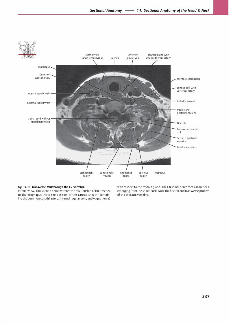
8/15/2019 Head and Neck Anatomy for Dental Medicine - Thieme; (January 26, 2010)
http://slidepdf.com/reader/full/head-and-neck-anatomy-for-dental-medicine-thieme-january-26-2010 350/384
Anterior scaleneExternal jugular vein
Internal jugular vein
Spinal cord with C8spinal nerve root
Levator scapulae
Transverse processof T1
Serratus posteriorsuperior
First rib
Middle and
posterior scalene
Longus colli withvertebral artery
Commoncarotid artery Sternocleidomastoid
Esophagus
Sternohyoidand s ternothyroid Trachea
Anterior jugular vein
Thyroid gland withinferior thyroid artery
Semispinaliscapitis
Semispinaliscervicis
Rhomboidminor
Spleniuscapitis
Trapezius
Fig. 14.32 Transverse MRI through the C7 vertebra
Inferior view. This section demonstrates the relationship of the trachea
to the esophagus. Note the position of the carotid sheath (contain-
ing the common carotid artery, internal jugular vein, and vagus nerve)
with respect to the thyroid gland. The C8 spinal nerve root can be seen
emerging from the spinal cord. Note the first rib and transverse process
of the thoracic vertebra.
337
Sectional Anatomy 14. Sectional Anatomy of the Head & Neck
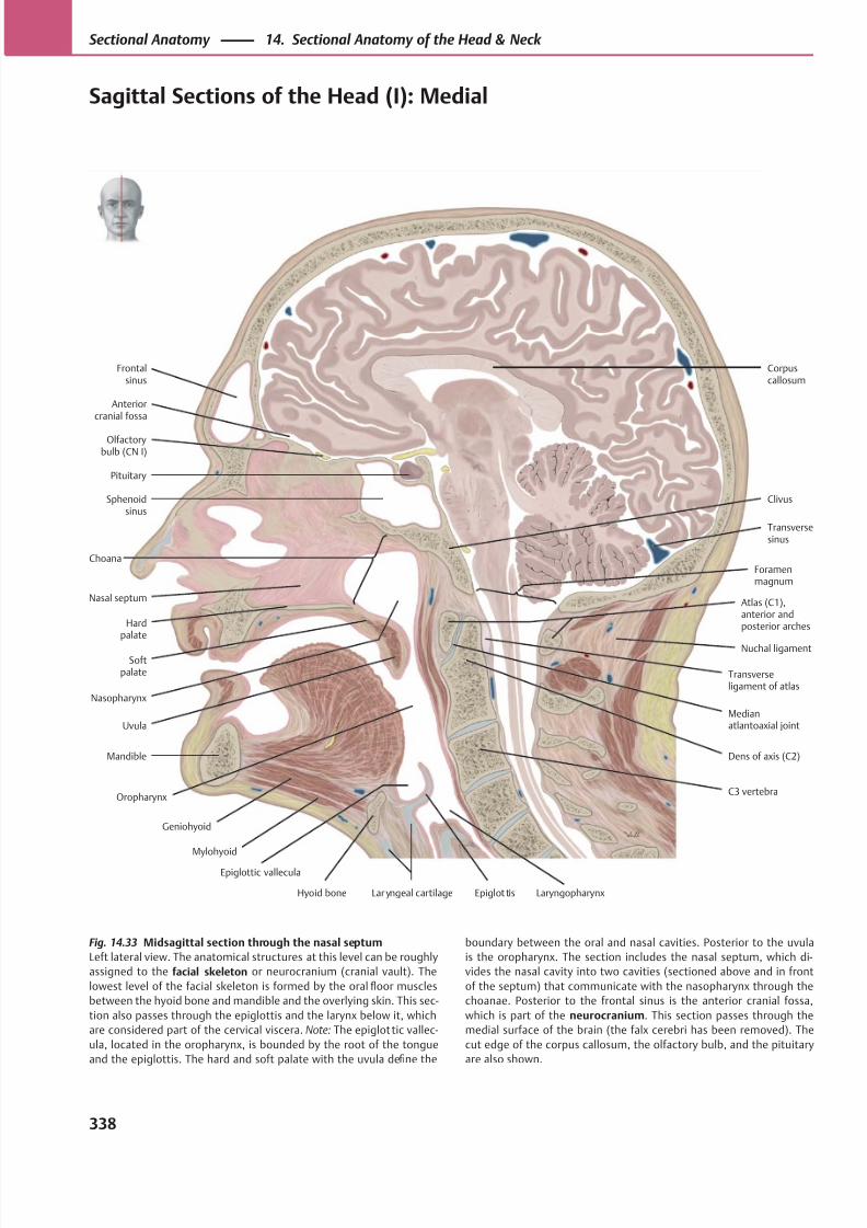
8/15/2019 Head and Neck Anatomy for Dental Medicine - Thieme; (January 26, 2010)
http://slidepdf.com/reader/full/head-and-neck-anatomy-for-dental-medicine-thieme-january-26-2010 351/384
Olfactorybulb (CN I)
Anteriorcranial fossa
Frontalsinus
Clivus
Nasal septum
Hardpalate
Softpalate
Uvula
Mylohyoid
Geniohyoid
Hyoid bone Lar yngeal cartilage Epiglot tis
Choana
C3 vertebra
Dens of axis (C2)
Medianatlantoaxial joint
Nasopharynx
Nuchal ligament
Atlas (C1),anterior andposterior arches
Transversesinus
Transverseligament of atlas
Foramenmagnum
Pituitary
Sphenoidsinus
Corpuscallosum
Mandible
Laryngopharynx
Epiglottic vallecula
Oropharynx
Fig. 14.33 Midsagittal section through the nasal septum
Left lateral view. The anatomical structures at this level can be roughly
assigned to the facial skeleton or neurocranium (cranial vault). The
lowest level of the facial skeleton is formed by the oral floor muscles
between the hyoid bone and mandible and the overlying skin. This sec-
tion also passes through the epiglottis and the larynx below it, which
are considered part of the cervical viscera. Note: The epiglottic vallec-
ula, located in the oropharynx, is bounded by the root of the tongue
and the epiglottis. The hard and soft palate with the uvula define the
boundary between the oral and nasal cavities. Posterior to the uvula
is the oropharynx. The section includes the nasal septum, which di-
vides the nasal cavity into two cavities (sectioned above and in front
of the septum) that communicate with the nasopharynx through the
choanae. Posterior to the frontal sinus is the anterior cranial fossa,
which is part of the neurocranium. This section passes through the
medial surface of the brain (the falx cerebri has been removed). The
cut edge of the corpus callosum, the olfactory bulb, and the pituitary
are also shown.
338
Sectional Anatomy 14. Sectional Anatomy of the Head & Neck
Sagittal Sections of the Head (I): Medial
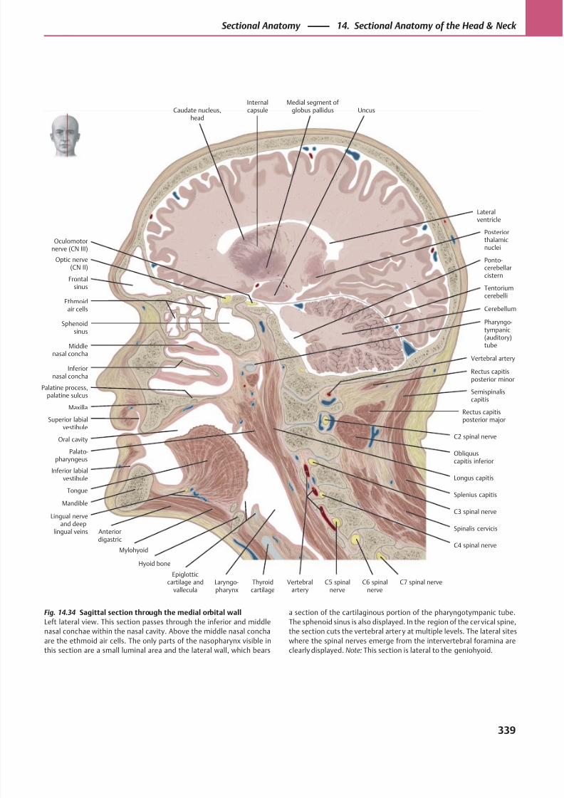
8/15/2019 Head and Neck Anatomy for Dental Medicine - Thieme; (January 26, 2010)
http://slidepdf.com/reader/full/head-and-neck-anatomy-for-dental-medicine-thieme-january-26-2010 352/384
Vertebralartery
Oculomotornerve (CN III)
Optic nerve(CN II)
Frontalsinus
Ethmoidair cells
Sphenoidsinus
Middlenasal concha
Inferiornasal concha
Maxilla
Superior labialvestibule
Palatine process,palatine sulcus
Longus capitis
Palato-pharyngeus
Mandible
Anteriordigastric
Lingual nerveand deep
lingual veins
Mylohyoid
Tongue
Hyoid bone
Epiglotticcartilage and
valleculaThyroidcartilage
C7 spinal nerveC6 spinalnerve
Spinalis cervicis
C5 spinalnerve
C4 spinal nerve
Laryngo-pharynx
C3 spinal nerve
C2 spinal nerve
Splenius capitis
Obliquuscapitis inferior
Rectus capitis
posterior major
Semispinaliscapitis
Vertebral artery
Rectus capitisposterior minor
Oral cavity
Pharyngo-tympanic(auditory)tube
Cerebellum
Ponto-cerebellarcistern
Posteriorthalamicnuclei
UncusMedial segment of
globus pallidusInternalcapsuleCaudate nucleus,
head
Lateralventricle
Inferior labialvestibule
Tentoriumcerebelli
Fig. 14.34 Sagittal section through the medial orbital wall
Left lateral view. This section passes through the inferior and middle
nasal conchae within the nasal cavity. Above the middle nasal concha
are the ethmoid air cells. The only parts of the nasopharynx visible in
this section are a small luminal area and the lateral wall, which bears
a section of the cartilaginous portion of the pharyngotympanic tube.
The sphenoid sinus is also displayed. In the region of the cervical spine,
the section cuts the vertebral arter y at multiple levels. The lateral sites
where the spinal nerves emerge from the intervertebral foramina are
clearly displayed. Note: This section is lateral to the geniohyoid.
339
Sectional Anatomy 14. Sectional Anatomy of the Head & Neck
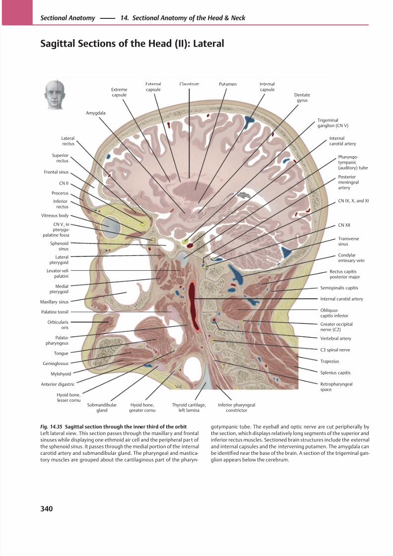
8/15/2019 Head and Neck Anatomy for Dental Medicine - Thieme; (January 26, 2010)
http://slidepdf.com/reader/full/head-and-neck-anatomy-for-dental-medicine-thieme-january-26-2010 353/384
Frontal sinus
Procerus
Superiorrectus
Vitreous body
Lateralrectus
CN II
Inferiorrectus
CN V2 in
pterygo-palatine fossa
Sphenoidsinus
Maxillary sinus
Lateralpterygoid
Pharyngo-tympanic(auditory) tube
Medial
pterygoid
Orbicularisoris
Levator velipalatini
Mylohyoid
Genioglossus
Anterior digastric
Tongue
Palatine tonsil
Palato-pharyngeus
Submandibulargland
Hyoid bone,greater cornu
Thyroid cartilage,left lamina
Inferior pharyngealconstrictor
Hyoid bone,lesser cornu
Retropharyngeal
space
C3 spinal nerve
Trapezius
Splenius capitis
Semispinalis capitis
Rectus capitisposterior major
Vertebral artery
Condylaremissary vein
CN XII
Transversesinus
Posteriormeningealartery
CN IX, X, and XI
Internalcarotid artery
Trigeminalganglion (CN V)
Dentategyrus
Putamen Internalcapsule
Externalcapsule
ClaustrumExtreme
capsule
Amygdala
Obliquuscapitis inferior
Greater occipitalnerve (C2)
Internal carotid artery
Fig. 14.35 Sagittal section through the inner third of the orbit
Left lateral view. This section passes through the maxillary and frontal
sinuses while displaying one ethmoid air cell and the peripheral par t of
the sphenoid sinus. It passes through the medial portion of the internal
carotid artery and submandibular gland. The pharyngeal and mastica-
tory muscles are grouped about the cartilaginous part of the pharyn-
gotympanic tube. The eyeball and optic nerve are cut peripherally by
the section, which displays relatively long segments of the superior and
inferior rectus muscles. Sectioned brain structures include the external
and internal capsules and the intervening putamen. The amygdala can
be identified near the base of the brain. A section of the trigeminal gan-
glion appears below the cerebrum.
340
Sectional Anatomy 14. Sectional Anatomy of the Head & Neck
Sagittal Sections of the Head (II): Lateral
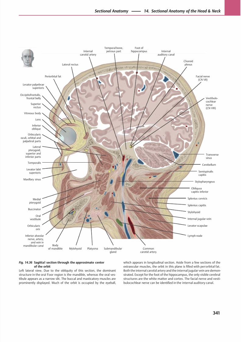
8/15/2019 Head and Neck Anatomy for Dental Medicine - Thieme; (January 26, 2010)
http://slidepdf.com/reader/full/head-and-neck-anatomy-for-dental-medicine-thieme-january-26-2010 354/384
Occipitofrontalis,frontal belly
Periorbital fat
Levator palpebraesuperioris
Internalauditory canal
Superiorrectus
Vitreous body
Lens
Orbicularisoculi, orbital and
palpebral parts
Inferioroblique
Lateral rectus
Levator labiisuperioris
Maxillary sinus
Orbicularisoris
Buccinator
Oralvestibule
Bodyof mandible
Inferior alveolar
nerve, artery,and vein in
mandibular canalSubmandibular
gland
Lymph node
Mylohyoid
Vestibulo-cochlearnerve(CN VIII)
Commoncarotid artery
Levator scapulae
Foot of hippocampus
Internal jugular vein
Stylohyoid
Splenius capitis
Splenius cervicis
Semispinaliscapitis
Obliquuscapitis inferior
Stylopharyngeus
Cerebellum
Transversesinus
Facial nerve(CN VII)
Medialpterygoid
Lateralpterygoid,
superior andinferior parts
Temporalis
Temporal bone,petrous partInternal
carotid artery
Choroidplexus
Platysma
Fig. 14.36 Sagittal section through the approximate center
of the orbit
Left lateral view. Due to the obliquity of this section, the dominant
structure in the oral floor region is the mandible, whereas the oral ves-
tibule appears as a narrow slit. The buccal and masticatory muscles are
prominently displayed. Much of the orbit is occupied by the eyeball,
which appears in longitudinal section. Aside from a few sections of the
extraocular muscles, the orbit in this plane is filled with periorbital fat.
Both the internal carotid artery and the internal jugular vein are demon-
strated. Except for the foot of the hippocampus, the only visible cerebral
structures are the white matter and cortex. The facial nerve and vesti-
bulocochlear nerve can be identified in the internal auditory canal.
341
Sectional Anatomy 14. Sectional Anatomy of the Head & Neck
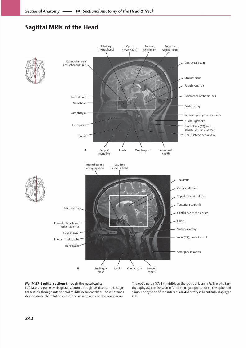
8/15/2019 Head and Neck Anatomy for Dental Medicine - Thieme; (January 26, 2010)
http://slidepdf.com/reader/full/head-and-neck-anatomy-for-dental-medicine-thieme-january-26-2010 355/384
Fourth ventricle
Nasal bone
Frontal sinus
Hard palate
Nasopharynx
C2/C3 intervertebral disk
Dens of axis (C2) andanterior arch of atlas (C1)
Rectus capitis posterior minor
Nuchal ligament
Basilar artery
Confluence of the sinuses
Straight sinus
Ethmoid air cellsand sphenoid sinus
Tongue
Semispinaliscapitis
Corpus callosum
Opticnerve (CN II)
Septumpellucidum
Superiorsagittal sinus
Body of mandible
Uvula OropharynxA
Pituitary(hypophysis)
Corpus callosum
Ethmoid air cells andsphenoid sinus
Frontal sinus
Inferior nasal concha
Nasopharynx
Atlas (C1), posterior arch
Vertebral artery
Confluence of the sinuses
Clivus
Tentorium cerebelli
Superior sagittal sinus
Thalamus
Internal carotidartery, syphon
Hard palate
Semispinalis capitis
Caudatenucleus, head
Sublingualgland
Uvula Oropharynx Longuscapitis
B
Fig. 14.37 Sagittal sections through the nasal cavity
Left lateral view. A Midsagittal section through nasal septum. B Sagit-
tal section through inferior and middle nasal conchae. These sections
demonstrate the relationship of the nasopharynx to the oropharynx.
The optic nerve (CN II) is visible as the optic chiasm in A. The pituitary
(hypophysis) can be seen inferior to it, just posterior to the sphenoid
sinus. The syphon of the internal carotid artery is beautifully displayed
in B.
342
Sectional Anatomy 14. Sectional Anatomy of the Head & Neck
Sagittal MRIs of the Head
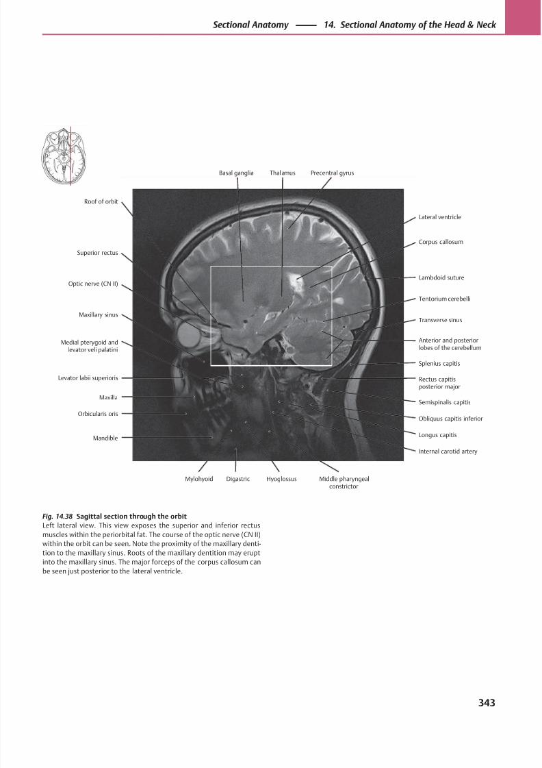
8/15/2019 Head and Neck Anatomy for Dental Medicine - Thieme; (January 26, 2010)
http://slidepdf.com/reader/full/head-and-neck-anatomy-for-dental-medicine-thieme-january-26-2010 356/384
Lambdoid suture
Superior rectus
Roof of orbit
Levator labii superioris
Maxilla
Maxillary sinus
Optic nerve (CN II)
Longus capitis
Semispinalis capitis
Rectus capitisposterior major
Anterior and posteriorlobes of the cerebellum
Splenius capitis
Transverse sinus
Tentorium cerebelli
Corpus callosum
Basal ganglia
Orbicularis oris
Medial pterygoid andlevator veli palatini
Obliquus capitis inferior
Lateral ventricle
Thalamus Precentral gyrus
Mandible
Mylohyoid Digastric Hyoglossus Middle pharyngealconstrictor
Internal carotid artery
Fig. 14.38 Sagittal section through the orbit
Left lateral view. This view exposes the superior and inferior rectus
muscles within the periorbital fat. The course of the optic nerve (CN II)within the orbit can be seen. Note the proximity of the maxillary denti-
tion to the maxillary sinus. Roots of the maxillary dentition may erupt
into the maxillary sinus. The major forceps of the corpus callosum can
be seen just posterior to the lateral ventricle.
343
Sectional Anatomy 14. Sectional Anatomy of the Head & Neck
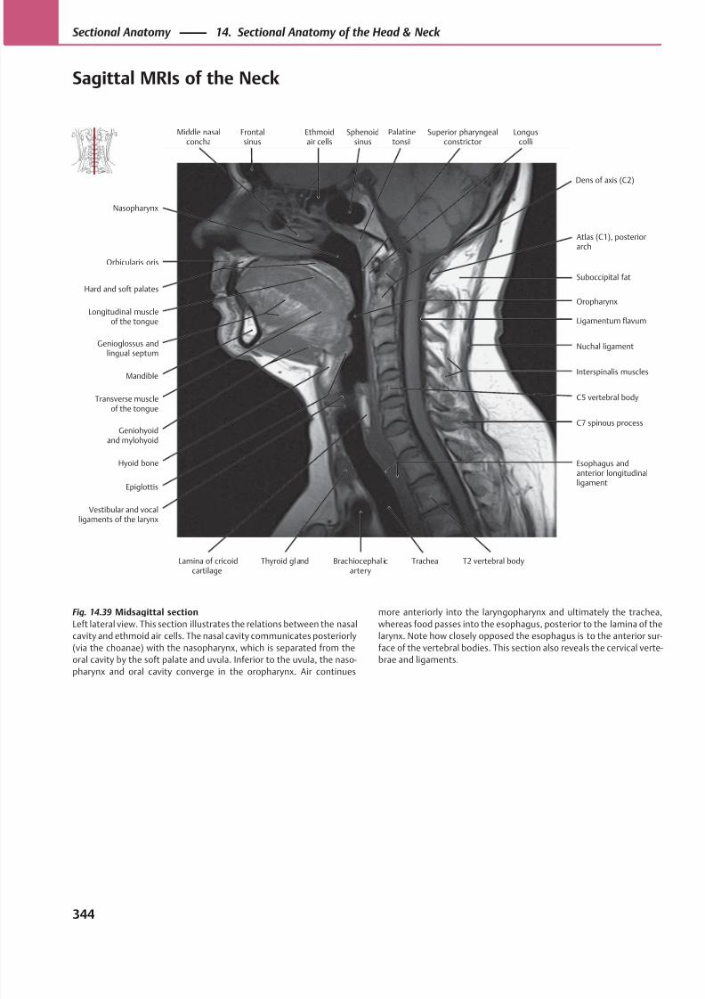
8/15/2019 Head and Neck Anatomy for Dental Medicine - Thieme; (January 26, 2010)
http://slidepdf.com/reader/full/head-and-neck-anatomy-for-dental-medicine-thieme-january-26-2010 357/384
Superior pharyngealconstrictor
Oropharynx
Orbicularis oris
Nasopharynx
Mandible
Transverse muscleof the tongue
Longitudinal muscleof the tongue
Hard and soft palates
Epiglottis
Esophagus andanterior longitudinalligament
C7 spinous process
Interspinalis muscles
C5 vertebral body
Nuchal ligament
Ligamentum flavum
Suboccipital fat
Middle nasalconcha
Hyoid bone
Geniohyoidand mylohyoid
Genioglossus andlingual septum
Atlas (C1), posteriorarch
Frontalsinus
Ethmoidair cells
Sphenoidsinus
Palatinetonsil
Dens of axis (C2)
Vestibular and vocalligaments of the larynx
Lamina of cricoidcartilage
Thyroid gland Brachiocephal icartery
Trachea T2 vertebral body
Longuscolli
Fig. 14.39 Midsagittal section
Left lateral view. This section illustrates the relations between the nasal
cavity and ethmoid air cells. The nasal cavity communicates posteriorly
(via the choanae) with the nasopharynx, which is separated from the
oral cavity by the soft palate and uvula. Inferior to the uvula, the naso-
pharynx and oral cavity converge in the oropharynx. Air continues
more anteriorly into the laryngopharynx and ultimately the trachea,
whereas food passes into the esophagus, posterior to the lamina of the
larynx. Note how closely opposed the esophagus is to the anterior sur-
face of the vertebral bodies. This section also reveals the cervical verte-
brae and ligaments.
344
Sectional Anatomy 14. Sectional Anatomy of the Head & Neck
Sagittal MRIs of the Neck
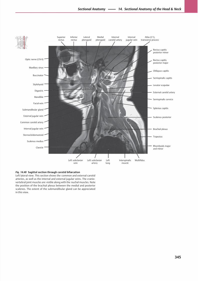
8/15/2019 Head and Neck Anatomy for Dental Medicine - Thieme; (January 26, 2010)
http://slidepdf.com/reader/full/head-and-neck-anatomy-for-dental-medicine-thieme-january-26-2010 358/384

8/15/2019 Head and Neck Anatomy for Dental Medicine - Thieme; (January 26, 2010)
http://slidepdf.com/reader/full/head-and-neck-anatomy-for-dental-medicine-thieme-january-26-2010 359/384
8/15/2019 Head and Neck Anatomy for Dental Medicine - Thieme; (January 26, 2010)
http://slidepdf.com/reader/full/head-and-neck-anatomy-for-dental-medicine-thieme-january-26-2010 360/384
Appendix
References . . . . . . . . . . . . . . . . . . . . . . . . . . . . . . . . . . . . . . . . 348
Index . . . . . . . . . . . . . . . . . . . . . . . . . . . . . . . . . . . . . . . . . . . . . . 349
8/15/2019 Head and Neck Anatomy for Dental Medicine - Thieme; (January 26, 2010)
http://slidepdf.com/reader/full/head-and-neck-anatomy-for-dental-medicine-thieme-january-26-2010 361/384
348
References
Becker W, Naumann HH, Pfaltz CR. Otorhinolaryngology [in
German]. 2nd ed. Stuttgart: Thieme; 1983
Faller A, Poisel S, Golth D, Faller A, Schuenke M. The Human Body [in
German]. 14th ed. Stuttgart: Thieme; 2004
Kahle W, Frotscher M. Pocket Atlas of Anatomy [in German]. Vol. 3.
9th ed. Stuttgart : Thieme; 2005
Lippert H, Pabst R. Arterial Variations in Man. Munich: Bergmann;
1985
Platzer W. Pocket Atlas of Anatomy [in German]. Vol. 1. Stuttgart:
Thieme; 1999
Platzer W. Topographic Anatomy Atlas [in German]. Stuttgart:
Thieme; 1982Rauber A, Kopsch F. Human Anatomy [in German]. Vol. 1–4.
Stuttgart: Thieme; Vol. 1, 2: 1997; Vol. 2, 3: 1987; Vol. 4: 1988
Schmidt F. Innervation of the Temporomandibular Joint [in German].
Gegenbaurs morphol. Jb. 1067:110;554-573
Tillmann B. Color Atlas of Anatomy Dental Medicine — Human Medicine
[in German]. Stuttgart: Thieme; 1997
Vahlensieck M, Reiser M. MRI of the Musculoskeletal System [in
German]. 2nd ed. Stuttgart: Thieme; 2001
Vahlensieck M, Reiser M, eds. MRI of the Musculoskeletal System [in
German]. 2nd rev. ed. Berlin: Springer; 1959
von Lanz T, Wachsmuth W. Applied Anatomy [in German]. Vol. 2, Part
6 (Loeweneck H, Feifel G, eds.), Berlin: Springer; 1993
von Lanz T, Wachsmuth W. Applied Anatomy [in German]. Vol. 1, 2:
Hals, Berlin: Springer; 1955
8/15/2019 Head and Neck Anatomy for Dental Medicine - Thieme; (January 26, 2010)
http://slidepdf.com/reader/full/head-and-neck-anatomy-for-dental-medicine-thieme-january-26-2010 362/384
A
Abdomen
muscles (internal/external obliques) of, 242
vagus nerve branches to, 91t
Abducent nerve (CN VI), 66t, 72, 72t, 114t
emergence from brainstem, 114
eye movement and, 140
function of, 67t
Abducent nerve palsy, 72t, 113, 114t
Abducting nystagmus, 141
Accessory lacrimal glands, 122
Accessory meningeal artery, 45t, 47t
Accessory parotid gland, 218
Accessory spinal nerve (CN XI), 66t, 92
anterior cervical triangle and, 281
course of, 92t
in deep lateral cervical region, 283
function of, 67t
in lateral neck, 278
nerve lesions of, 92, 92t
in nuchal region, 276
nuclei, ganglia, and fiber distribution of, 92t
spinal contribution to, 291
on transverse MRI of head, 333
in transverse section of headthrough C5 level, 328
through nasopharynx, 326
Accessory visual system, 137
Accommodation, pathways for, 138
Acoustic neuroma, 87, 165, 168
Acromion, inferior boundary of neck and, 273
Action potential, 306
Adam’s apple. See Thyroid cartilage
Aff erent impulses, in gustatory pathway, 222
Aff erent (motor) fibers, 54, 66t, 291
brainstem reflexes and, 137
facial nerve and, 82t
Aff erent nuclei, 68t, 69
Aff erent tracts. See Sensory (aff erent) pathwaysAge-related changes
in cranial sutures and fontanelles, 3, 3t
in mandible, 23, 192
in spinal cord segment levels, 299
Ageusia, 222
Air pressure equalization, 161
Airways, on coronal MRI of neck, 317
Alae, 142
Alar cartilage, 142
Alar ligaments, 236, 237
Alveolar arteries, 44, 45t
Alveolar bone, 182, 182t
Alveolar processes of teeth, 23
Alzheimer disease, neurofibrils in, 306
Amacrine cells, 133
Amaurosis, 136, 139
American Academy of Otolaryngology, deep cervical lymph node
groups and, 268
Ampulla, 174
Ampullary crest, 174
Amygdala, in sagittal section of head, 340
Anastomosis
arterial, in face, 97
in arterial supply to auricle, 157
Anesthesia, epidural and lumbar,299
Angular vein, infection transmission and, 52t
Anosmia, 222
Ansa cervicalis, 270, 282
Anterior auricular arteries, 157
Anterior cerebral artery, 305
Anterior cervical triangle, 272, 272t
dissection of, 280–281
Anterior communicating artery, 305
Anterior cranial fossa, 310
Anterior ethmoid nerve, 76, 77t
Anterior jugular vein, 50–51, 51t
Anterior olfactory stria, 152
Anterior rhinoscopy, 151
Anterior tympanic artery, 44, 45t, 47t, 166, 166tApical ligaments of the dens, 237
Aqueous humor, drainage of, 131
obstructed, glaucoma and, 131
Arachnoid, 296
Arcuate eminence, 155
Argyll Robertson pupil, 138
Arterial grooves, in calvaria, 10
Arterial supply
to brain, 304
stenoses and occlusions of, 305
to thyroid gland, 265
Artery(ies). See also individually named arteries
of auricle, 157
in circle of Willis, 305
of ear, 166–167, 166t
of infratemporal fossa, 102–103, 102t
laryngeal, 261
ligation sites for nosebleed, 151
of neck, 266, 266t
of pterygoid canal, 45t, 46, 47t
of right lateral nasal wall, 148, 149
superficial, of head, 99
of tongue, 220
Articular disk
in temporomandibular joint, 37
on coronal MRI of neck, 319
on transverse MRI of neck, 334
Index
Note: Tabular material is indicated by a “t” following the page number.
349
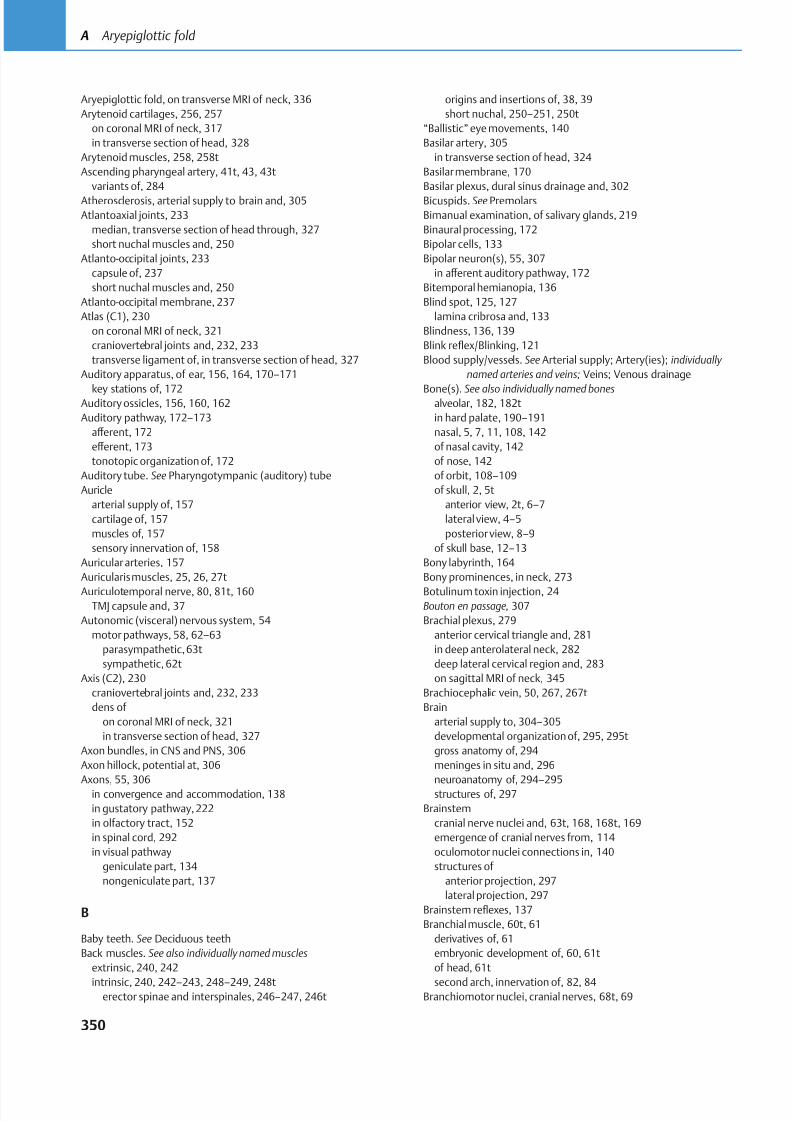
8/15/2019 Head and Neck Anatomy for Dental Medicine - Thieme; (January 26, 2010)
http://slidepdf.com/reader/full/head-and-neck-anatomy-for-dental-medicine-thieme-january-26-2010 363/384
Aryepiglottic fold, on transverse MRI of neck, 336
Arytenoid cartilages, 256, 257
on coronal MRI of neck, 317
in transverse section of head, 328
Arytenoid muscles, 258, 258t
Ascending pharyngeal artery, 41t, 43, 43t
variants of, 284
Atherosclerosis, arterial supply to brain and, 305
Atlantoaxial joints, 233
median, transverse section of head through, 327
short nuchal muscles and, 250
Atlanto-occipital joints, 233
capsule of, 237
short nuchal muscles and, 250
Atlanto-occipital membrane, 237
Atlas (C1), 230
on coronal MRI of neck, 321
craniovertebral joints and, 232, 233
transverse ligament of, in transverse section of head, 327
Auditory apparatus, of ear, 156, 164, 170–171
key stations of, 172Auditory ossicles, 156, 160, 162
Auditory pathway, 172–173
aff erent, 172
eff erent, 173
tonotopic organization of, 172
Auditory tube. See Pharyngotympanic (auditory) tube
Auricle
arterial supply of, 157
cartilage of, 157
muscles of, 157
sensory innervation of, 158
Auricular arteries, 157
Auricularis muscles, 25, 26, 27t
Auriculotemporal nerve, 80, 81t, 160TMJ capsule and, 37
Autonomic (visceral) nervous system, 54
motor pathways, 58, 62–63
parasympathetic,63t
sympathetic, 62t
Axis (C2), 230
craniovertebral joints and, 232, 233
dens of
on coronal MRI of neck, 321
in transverse section of head, 327
Axon bundles, in CNS and PNS, 306
Axon hillock, potential at, 306
Axons, 55, 306in convergence and accommodation, 138
in gustatory pathway, 222
in olfactory tract, 152
in spinal cord, 292
in visual pathway
geniculate part, 134
nongeniculate part, 137
B
Baby teeth. See Deciduous teeth
Back muscles. See also individually named muscles
extrinsic, 240, 242
intrinsic, 240, 242–243, 248–249, 248terector spinae and interspinales,246–247, 246t
origins and insertions of, 38, 39
short nuchal, 250–251, 250t
“Ballistic” eye movements, 140
Basilar artery, 305
in transverse section of head, 324
Basilar membrane, 170
Basilar plexus, dural sinus drainage and, 302
Bicuspids. See Premolars
Bimanual examination, of salivary glands, 219
Binaural processing, 172
Bipolar cells, 133
Bipolar neuron(s), 55, 307
in aff erent auditory pathway, 172
Bitemporal hemianopia, 136
Blind spot, 125, 127
lamina cribrosa and, 133
Blindness, 136, 139
Blink reflex/Blinking, 121
Blood supply/vessels. See Arterial supply; Artery(ies); individually
named arteries and veins; Veins; Venous drainage
Bone(s). See also individually named bonesalveolar, 182, 182t
in hard palate, 190–191
nasal, 5, 7, 11, 108, 142
of nasal cavity, 142
of nose, 142
of orbit, 108–109
of skull, 2, 5t
anterior view, 2t, 6–7
lateral view, 4–5
posterior view, 8–9
of skull base, 12–13
Bony labyrinth, 164
Bony prominences, in neck, 273
Botulinum toxin injection, 24Bouton en passage, 307
Brachial plexus, 279
anterior cervical triangle and, 281
in deep anterolateral neck, 282
deep lateral cervical region and, 283
on sagittal MRI of neck, 345
Brachiocephalic vein, 50, 267, 267t
Brain
arterial supply to, 304–305
developmental organization of, 295, 295t
gross anatomy of, 294
meninges in situ and, 296
neuroanatomy of, 294–295structures of, 297
Brainstem
cranial nerve nuclei and, 63t, 168, 168t, 169
emergence of cranial nerves from, 114
oculomotor nuclei connections in, 140
structures of
anterior projection, 297
lateral projection, 297
Brainstem reflexes, 137
Branchial muscle, 60t, 61
derivatives of, 61
embryonic development of, 60, 61t
of head, 61t
second arch, innervation of, 82, 84Branchiomotor nuclei, cranial nerves, 68t, 69
350
A Aryepiglottic fold
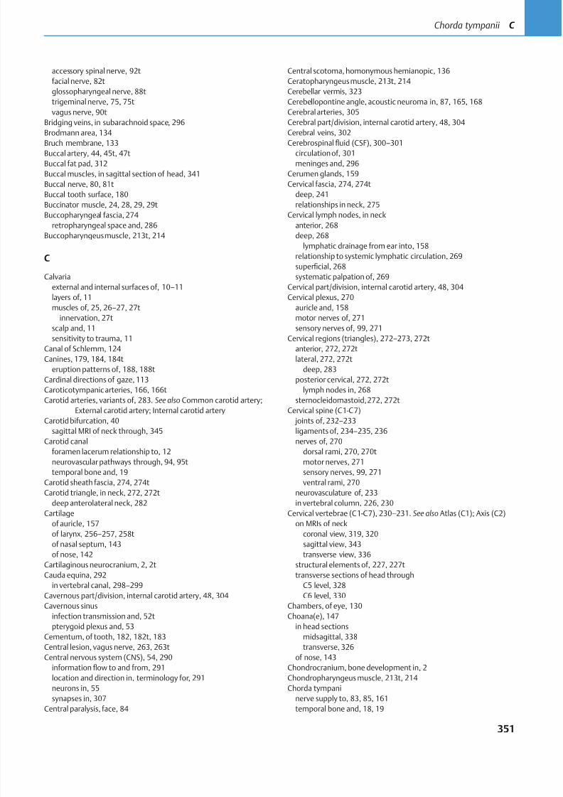
8/15/2019 Head and Neck Anatomy for Dental Medicine - Thieme; (January 26, 2010)
http://slidepdf.com/reader/full/head-and-neck-anatomy-for-dental-medicine-thieme-january-26-2010 364/384
accessory spinal nerve, 92t
facial nerve, 82t
glossopharyngeal nerve, 88t
trigeminal nerve, 75, 75t
vagus nerve, 90t
Bridging veins, in subarachnoid space, 296
Brodmann area, 134
Bruch membrane, 133
Buccal artery, 44, 45t, 47t
Buccal fat pad, 312
Buccal muscles, in sagittal section of head, 341
Buccal nerve, 80, 81t
Buccal tooth surface, 180
Buccinator muscle, 24, 28, 29, 29t
Buccopharyngeal fascia, 274
retropharyngeal space and, 286
Buccopharyngeus muscle, 213t, 214
C
Calvariaexternal and internal surfaces of, 10–11
layers of, 11
muscles of, 25, 26–27, 27t
innervation, 27t
scalp and, 11
sensitivity to trauma, 11
Canal of Schlemm, 124
Canines, 179, 184, 184t
eruption patterns of, 188, 188t
Cardinal directions of gaze,113
Caroticotympanic arteries, 166, 166t
Carotid arteries, variants of, 283. See also Common carotid artery;
External carotid artery; Internal carotid artery
Carotid bifurcation, 40sagittal MRI of neck through, 345
Carotid canal
foramen lacerum relationship to, 12
neurovascular pathways through, 94, 95t
temporal bone and, 19
Carotid sheath fascia, 274, 274t
Carotid triangle, in neck, 272, 272t
deep anterolateral neck, 282
Cartilage
of auricle, 157
of larynx, 256–257, 258t
of nasal septum, 143
of nose, 142Cartilaginous neurocranium, 2, 2t
Cauda equina, 292
in vertebral canal, 298–299
Cavernous part/division, internal carotid artery, 48, 304
Cavernous sinus
infection transmission and, 52t
pterygoid plexus and, 53
Cementum, of tooth, 182, 182t, 183
Central lesion, vagus nerve, 263, 263t
Central nervous system (CNS), 54, 290
information flow to and from, 291
location and direction in, terminology for, 291
neurons in, 55
synapses in, 307Central paralysis, face, 84
Central scotoma, homonymous hemianopic, 136
Ceratopharyngeus muscle, 213t, 214
Cerebellar vermis, 323
Cerebellopontine angle, acoustic neuroma in, 87, 165, 168
Cerebral arteries, 305
Cerebral part/division, internal carotid artery, 48, 304
Cerebral veins, 302
Cerebrospinalfluid (CSF), 300–301
circulation of, 301
meninges and, 296
Cerumen glands, 159
Cervical fascia, 274, 274t
deep, 241
relationships in neck, 275
Cervical lymph nodes, in neck
anterior, 268
deep, 268
lymphatic drainage from ear into, 158
relationship to systemic lymphatic circulation, 269
superficial, 268
systematic palpation of, 269Cervical part/division, internal carotid artery, 48, 304
Cervical plexus, 270
auricle and, 158
motor nerves of, 271
sensory nerves of, 99, 271
Cervical regions (triangles), 272–273, 272t
anterior, 272, 272t
lateral, 272, 272t
deep, 283
posterior cervical, 272, 272t
lymph nodes in, 268
sternocleidomastoid,272, 272t
Cervical spine (C1-C7)
joints of, 232–233ligaments of, 234–235, 236
nerves of, 270
dorsal rami, 270, 270t
motor nerves, 271
sensory nerves, 99, 271
ventral rami, 270
neurovasculature of, 233
in vertebral column, 226, 230
Cervical vertebrae (C1-C7), 230–231. See also Atlas (C1); Axis (C2)
on MRIs of neck
coronal view, 319, 320
sagittal view, 343
transverse view, 336structural elements of, 227, 227t
transverse sections of head through
C5 level, 328
C6 level, 330
Chambers, of eye, 130
Choana(e), 147
in head sections
midsagittal, 338
transverse, 326
of nose, 143
Chondrocranium, bone development in, 2
Chondropharyngeus muscle, 213t, 214
Chorda tympani
nerve supply to, 83, 85, 161temporal bone and, 18, 19
351
Chorda tympanii C
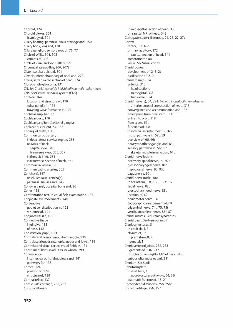
8/15/2019 Head and Neck Anatomy for Dental Medicine - Thieme; (January 26, 2010)
http://slidepdf.com/reader/full/head-and-neck-anatomy-for-dental-medicine-thieme-january-26-2010 365/384
Choroid, 124
Choroid plexus, 301
histology of, 301
Ciliary beating, paranasal sinus drainage and, 150
Ciliary body, lens and, 128
Ciliary ganglion, sensory root of, 76, 77
Circle of Willis, 304, 305
variants of, 305
Circle of Zinn (and von Haller), 127
Circumvallate papillae, 206, 207t
Cisterns, subarachnoid, 301
Clavicle, inferior boundary of neck and, 273
Clivus, in transverse section of head, 324
Closed-angle glaucoma, 131
CN. See Cranial nerve(s); individually named cranial nerves
CNS. See Central nervous system (CNS)
Cochlea, 164
location and structure of, 170
spiral ganglia in, 165
traveling wave formation in, 171
Cochlear amplifier, 173Cochlear duct, 170
Cochlear ganglion. See Spiral ganglia
Cochlear nuclei, 86t, 87, 168
Coding, of teeth, 180
Common carotid artery
in deep lateral cervical region, 283
on MRIs of neck
sagittal view, 345
transverse view, 335, 337
in thoracic inlet, 281
in transverse section of neck, 331
Common facial vein, 50
Communicating arteries, 305
Concha(e), 147nasal. See Nasal concha(e)
paranasal sinuses and, 145
Condylar canal, occipital bone and, 20
Cones, 133
Confrontation test, in visual field examination, 135
Conjugate eye movements, 140
Conjunctiva
goblet cell distribution in, 123
structure of, 121
Conjunctival sac, 121
Connective tissue
in gingiva, 183
of nose, 142Constriction, pupil, 130t
Contralateral homonymous hemianopia, 136
Contralateral quadrantanopia, upper and lower, 136
Contralateral visual cortex, visual fields in, 134
Conus medullaris, in adult vs. newborn, 299
Convergence
internuclear ophthalmoplegia and, 141
pathways for, 138
Cornea, 124
position of, 128
structure of, 129
Corneal reflex, 137
Corniculate cartilage, 256, 257
Corpus callosum
in midsagittal section of head, 338
on sagittal MRI of head, 343
Corrugator supercilii muscle, 24, 26, 27, 27t
Cortex
motor, 58t, 63t
primary auditory, 172
in sagittal section of head, 341
somatomotor, 84
visual. See Visual cortex
Cranial bones
development of, 2–3, 2t
ossification of, 2, 2t
Cranial fossa(e), 14
anterior, 310
in head sections
midsagittal, 338
transverse, 324
Cranial nerve(s), 54, 291. See also individually named nerves
in anterior coronal cross section of head, 313
convergence and accommodation and, 138
emergence from brainstem, 114entry into orbit, 118
fiber types, 66t
functions of, 67t
in internal acoustic meatus, 165
motor pathways in, 58t, 59
overview of, 66, 66t
parasympathetic ganglia and, 63
sensory pathways in, 56t, 57
in skeletal muscle innervation, 61t
Cranial nerve lesions
accessory spinal nerve, 92, 92t
glossopharyngeal nerve, 88t
hypoglossal nerve, 93, 93t
vagus nerve, 90tCranial nerve nuclei, 68t
in brainstem, 63t, 168, 168t, 169
facial nerve, 82t
glossopharyngeal nerve, 88t
location of, 69
oculomotor nerve, 140
topographic arrangement of, 68
trigeminal nerve, 74t, 75, 75t
vestibulocochlear nerve, 86t, 87
Cranial sutures. See Craniosynostoses
Cranial vault. See Neurocranium
Craniosynostoses, 8
in adult skull, 3closure of, 3t
premature, 8, 9
neonatal, 3
Craniovertebral joints, 232, 233
ligaments of, 236–237
muscles of, on sagittal MRI of neck, 345
suboccipital muscles and, 251
Cranium. See Skull
Cribriform plate
in skull base, 15
neurovascular pathways, 94, 95t
traumatic fracture of, 15, 21
Cricoarytenoid muscles, 258, 258t
Cricoid cartilage, 256, 257
352
C Choroid
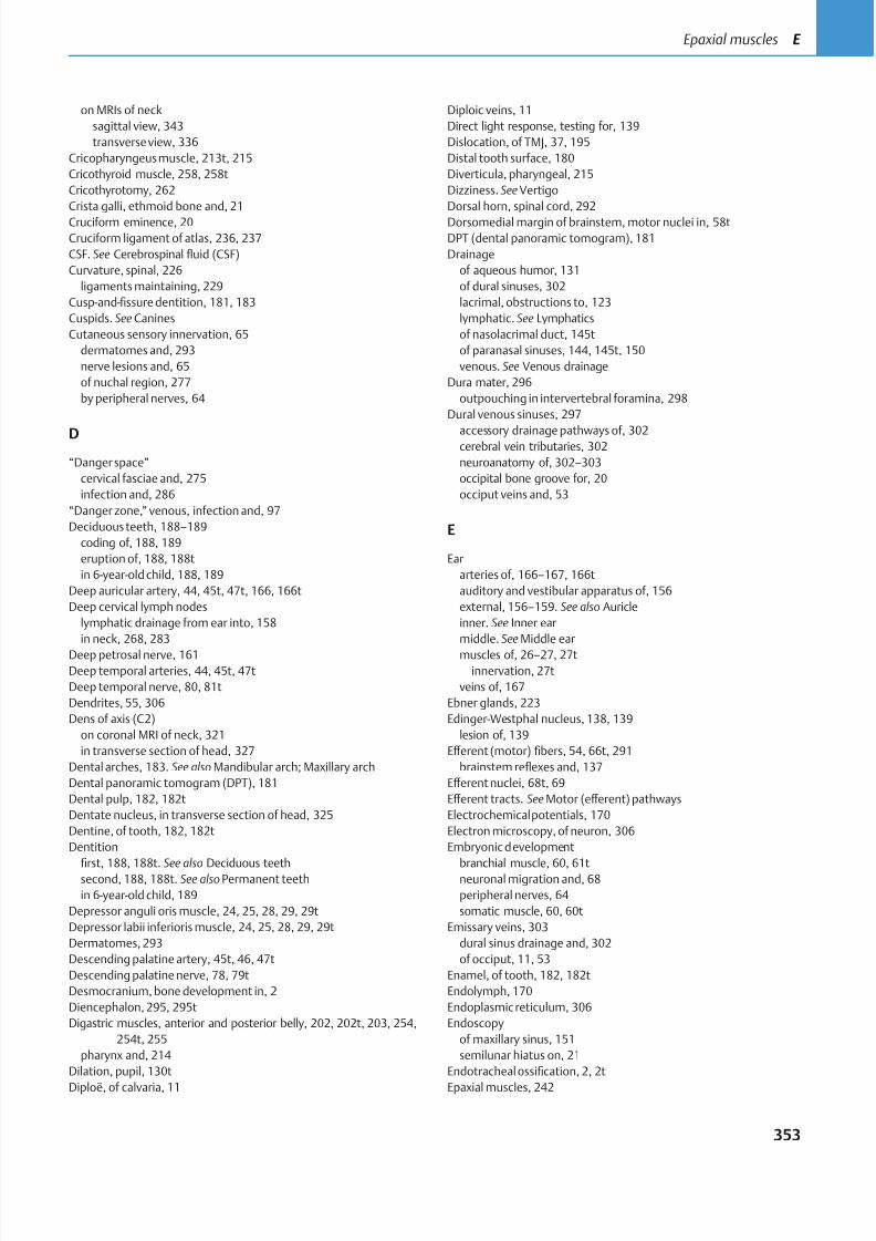
8/15/2019 Head and Neck Anatomy for Dental Medicine - Thieme; (January 26, 2010)
http://slidepdf.com/reader/full/head-and-neck-anatomy-for-dental-medicine-thieme-january-26-2010 366/384
on MRIs of neck
sagittal view, 343
transverse view, 336
Cricopharyngeus muscle, 213t, 215
Cricothyroid muscle, 258, 258t
Cricothyrotomy, 262
Crista galli, ethmoid bone and, 21
Cruciform eminence, 20
Cruciform ligament of atlas, 236, 237
CSF. See Cerebrospinal fluid (CSF)
Curvature, spinal, 226
ligaments maintaining, 229
Cusp-and-fissure dentition, 181, 183
Cuspids. See Canines
Cutaneous sensory innervation, 65
dermatomes and, 293
nerve lesions and, 65
of nuchal region, 277
by peripheral nerves, 64
D
“Danger space”
cervical fasciae and, 275
infection and, 286
“Danger zone,” venous, infection and, 97
Deciduous teeth, 188–189
coding of, 188, 189
eruption of, 188, 188t
in 6-year-old child, 188, 189
Deep auricular artery, 44, 45t, 47t, 166, 166t
Deep cervical lymph nodes
lymphatic drainage from ear into, 158
in neck, 268, 283
Deep petrosal nerve, 161Deep temporal arteries, 44, 45t, 47t
Deep temporal nerve, 80, 81t
Dendrites, 55, 306
Dens of axis (C2)
on coronal MRI of neck, 321
in transverse section of head, 327
Dental arches, 183. See also Mandibular arch; Maxillary arch
Dental panoramic tomogram (DPT), 181
Dental pulp, 182, 182t
Dentate nucleus, in transverse section of head, 325
Dentine, of tooth, 182, 182t
Dentition
first, 188, 188t. See also Deciduous teethsecond, 188, 188t. See also Permanent teeth
in 6-year-old child, 189
Depressor anguli oris muscle, 24, 25, 28, 29, 29t
Depressor labii inferioris muscle, 24, 25, 28, 29, 29t
Dermatomes, 293
Descending palatine artery, 45t, 46, 47t
Descending palatine nerve, 78, 79t
Desmocranium, bone development in, 2
Diencephalon, 295, 295t
Digastric muscles, anterior and posterior belly, 202, 202t, 203, 254,
254t, 255
pharynx and, 214
Dilation, pupil, 130t
Diploë, of calvaria, 11
Diploic veins, 11
Direct light response, testing for, 139
Dislocation, of TMJ, 37, 195
Distal tooth surface, 180
Diverticula, pharyngeal, 215
Dizziness. See Vertigo
Dorsal horn, spinal cord, 292
Dorsomedial margin of brainstem, motor nuclei in, 58t
DPT (dental panoramic tomogram), 181
Drainage
of aqueous humor, 131
of dural sinuses, 302
lacrimal, obstructions to, 123
lymphatic. See Lymphatics
of nasolacrimal duct, 145t
of paranasal sinuses, 144, 145t, 150
venous. See Venous drainage
Dura mater, 296
outpouching in intervertebral foramina, 298
Dural venous sinuses, 297
accessory drainage pathways of, 302cerebral vein tributaries, 302
neuroanatomy of, 302–303
occipital bone groove for, 20
occiput veins and, 53
E
Ear
arteries of, 166–167, 166t
auditory and vestibular apparatus of, 156
external, 156–159. See also Auricle
inner. See Inner ear
middle. See Middle ear
muscles of, 26–27, 27tinnervation, 27t
veins of, 167
Ebner glands, 223
Edinger-Westphal nucleus, 138, 139
lesion of, 139
Eff erent (motor) fibers, 54, 66t, 291
brainstem reflexes and, 137
Eff erent nuclei, 68t, 69
Eff erent tracts. See Motor (eff erent) pathways
Electrochemical potentials, 170
Electron microscopy, of neuron, 306
Embryonic development
branchial muscle, 60, 61tneuronal migration and, 68
peripheral nerves, 64
somatic muscle, 60, 60t
Emissary veins, 303
dural sinus drainage and, 302
of occiput, 11, 53
Enamel, of tooth, 182, 182t
Endolymph, 170
Endoplasmic reticulum, 306
Endoscopy
of maxillary sinus, 151
semilunar hiatus on, 21
Endotracheal ossification, 2, 2t
Epaxial muscles, 242
353
Epaxial muscles E
8/15/2019 Head and Neck Anatomy for Dental Medicine - Thieme; (January 26, 2010)
http://slidepdf.com/reader/full/head-and-neck-anatomy-for-dental-medicine-thieme-january-26-2010 367/384
Epicranial muscles, 25, 26
Epidural anesthesia, 299
Epiglottic cartilage, 256, 257
Epiglottic vallecula, in midsagittal section of head,338
Epiglottis, innervation of, 222
Epipharynx. See Nasopharynx
Epitympanum, 163
EPSP (excitatory postsynaptic potential), 306
Erb’s point, 270, 271, 278
Erector spinae, 242, 243
interspinales and, 246–247, 246t
Esophagus, on MRIs of neck
sagittal view, 343
transverse view, 337
Ethmoid air cells, 144, 310
relationship with nasal cavity, 343
in sagittal section of head, 339, 340
transverse MRI of head through, 332
Ethmoid arteries, ligation site for, 151
Ethmoid bone, 5, 7, 14, 21, 108, 142, 190, 191
cranial nerve passage through, 67tparanasal sinuses and, 145
Eustachian tube. See Pharyngotympanic (auditory) tube
Excitatory postsynaptic potential (EPSP), 306
External acoustic meatus, temporal bone and, 155
External auditory canal, 156, 159
auricle and, 158
curvature of, 159
temporal bone and, 155
External capsule, thyroid gland, 264
External carotid artery, 283
blood supply to anterior face from, 96
branches of, 40, 41, 41t. See also individually named arteries
anterior, 41t, 42, 43, 43t
medial, 41t, 42, 43tin neck, 266, 266t
posterior, 41t, 42, 43t
terminal, 41t, 46–47. See also Maxillary artery
variants in, 41
in carotid triangle, 282
in deep lateral cervical region, 283
on sagittal MRI of neck, 345
External ear, 156–159. See also Auricle
External jugular vein, 50–51, 51t
on sagittal MRI of neck, 345
External laryngeal nerve, 91, 91t
External occipital protuberance, superior boundary of neck, 273
Extracranial veins, infection and, 52tExtraocular muscles, 112
actions of, 113, 113t
cranial nerves of, 72, 72t
eye movement and, 140
innervation of, 112, 113t
Extrinsic muscles
of back, 240, 242
of eye. See Extraocular muscles
of tongue, 204, 204t, 205
Eye movement, coordination of, 140–141
Eye/Eyeball
blood supply to, 126–127
chambers of, 130
coronal MRI of head through, 314
muscles of, 26–27, 27t
innervation, 27t
reference lines/points of, 125
in sagittal section of head, 341
structure of, 124–125
surface anatomy of, 121
Eyelids, structure of, 121
F
Face
anterior, superficial neurovasculature of, 96
arterial anastomoses in, 97
cutaneous sensory innervation of, 64
venous “danger zone” in, 97
Facet joint capsules, of vertebral arch, 228
Facial artery
branches of, 42, 43t
external carotid artery and, 41t
nasal septum and, 149
ophthalmic artery and, 40, 41Facial expression, muscles of
calvaria, 26–27, 27t
ear, 26–27, 27t, 157
eye, 26–27, 27t
mouth, 28–29, 29t
origins and insertions of, 38
superficial
anterior view, 24
lateral view, 25
Facial motor nucleus, 82t
Facial nerve (CN VII), 66t, 82–85
in anterior face, 96
auricular muscles and, 157
brainstem reflexes and, 137branches of, 83
external, 84, 85
internal, 82, 83
in lateral head, 100
course of, 83
intraglandular, in parotid gland, 219
fiber distribution in, 82t
function of, 67t
ganglia, 82t, 85
in head sections
sagittal, 341
transverse, 325
innervation byof auricle, 158
of second branchial arch muscles, 82, 84
of tongue, 221, 222
in internal acoustic meatus, 165
nuclei of, 82t
parotid plexus of, 100, 101
in petrous bone, 161
temporal bone and, 18, 155
on transverse MRI of head, 332
Facial paralysis, facial nerve lesions and, 83, 84
Facial skeleton
ethmoid bone integration into, 21
in midsagittal section of head, 338
Facial skin, facial muscles and, 24
354
E Epicranial muscles
8/15/2019 Head and Neck Anatomy for Dental Medicine - Thieme; (January 26, 2010)
http://slidepdf.com/reader/full/head-and-neck-anatomy-for-dental-medicine-thieme-january-26-2010 368/384
Facial veins, 50, 51
False vocal cords, 260
Falx cerebri, 311, 313, 323
on coronal MRI of head, 315
ethmoid bone and, 21
Far vision/Farsightedness, 125, 129
Fascia(e)
buccopharyngeal,274, 286
cervical, 241, 274–275, 274t
nuchal. See Nuchal fascia
pharyngobasilar, 215
pretracheal. See Pretracheal fascia
prevertebral.See Prevertebral fascia
thoracolumbar, 241, 242, 243
Filiform papillae, 206, 207t
Filum terminale, 293
in vertebral canal, 298–299
First molars, 186t, 187
eruption patterns of, 188, 188t
Fissure
palpebral, muscles of, 26–27, 27tpetrotympanic. See Petrotympanic fissure
superior orbital, neurovascular pathways through, 67t, 94, 95t,
118
Foliate papillae, 206, 207t
Fontanelles, 3
closure of, 3t
Foodways, on coronal MRI of neck, 317
Foramen(ina). See also individually named foramina
intervertebral, 290, 297
jugular, 13, 20
for nerve supply to face, 6
of skull base, 15
neurovascular pathways through, 94, 95t
of sphenoid bone, 16, 17stylomastoid, 15
supraorbital, 6
Foramen cecum, 206, 207t
Foramen lacerum
carotid canal relationship to, 12
neurovascular pathways through, 94, 95t
Foramen magnum
neurovascular pathways through, 94, 95t
occipital bone and, 13, 20
Foramen ovale
cranial nerve passage through, 67t
dural sinus drainage and, 302
neurovascular pathways through, 94, 95tpterygoid process and, 16, 17
Foramen rotundum, 16, 17
cranial nerve passage through, 67t
neurovascular pathways through, 94, 95t
Foramen spinosum
neurovascular pathways through, 94, 95t
pterygoid process and, 16, 17
Force, lines of, in facial skeleton, 7
Forebrain, 295, 295t
Fornical conjunctiva, 121
Fovea centralis, 124, 132, 135
macula lutea and, 133
Fracture(s)
cribriform plate, 15, 21
midfacial, classification of, 7
skull base fracture lines, 14
temporal bone, facial nerve lesion and, 82t, 83
Frontal bone, 5, 7, 9, 11, 14, 108, 142
Frontal crest, in calvaria, 10
Frontal nerve, 76, 77t
Frontal sinus, 144, 146
ethmoid bone and, 145
fluid flow in, 150
pneumatization of, 144
on transverse MRI of head, 332
Fungiform papillae, 206, 207t
G
Galea aponeurotica, 24, 25, 26
Ganglion(ia)
ciliary, sensory root of, 76, 77
cranial nerve parasympathetic, 63
facial nerve, 85
geniculate, 82t, 83, 161, 170, 222inferior, 88t, 90t
nodose, 222
otic, 80, 81t, 88t, 89, 89t, 161
petrosal, 222
in PNS, nerve tracts and, 55
prevertebral,62t
pseudounipolar ganglion cells, 222
pterygopalatine,79t, 82t, 148
spinal, 290
spiral (cochlear), 86, 86t, 165, 170, 172, 173
submandibular, 80, 81t, 82t
superior, 88t, 90t
trigeminal, 340
vestibular, 86, 86t, 165, 174, 176Gaps, pharyngeal, 214t
Gastrulation, 60
Gaze, cardinal directions of, 113
Gaze centers, 140
Geniculate ganglion, 161, 170, 222
facial nerve and, 82t, 83
Genioglossus muscle, 204, 204t, 205
Geniohyoid muscle, 202, 202t, 203, 254, 254t, 255
Gennari, stria of, 134
Gingiva, 182, 182t
connective tissue fibers in, 183
Glaucoma, acute and chronic, 131
Glenoid fossa, of TMJ, 36, 194Glial cells, 133
Gliding movement, in TMJ, 34, 37, 196
Glomerulus, olfactory, 153
Glossoepiglottic folds, 207t
Glossoepiglottic valleculae, 207t
Glossopharyngeal nerve (CN IX), 66t, 88–89, 88t
branches of, 89, 89t
course of, 88t
function of, 67t
innervation by
of pharynx, 213t, 217
of tongue, 220, 221, 222
nuclei, ganglia, and fiber distribution, 88t
on transverse MRI of head, 333
355
Glossopharyngeal nerve (CN IX) G
8/15/2019 Head and Neck Anatomy for Dental Medicine - Thieme; (January 26, 2010)
http://slidepdf.com/reader/full/head-and-neck-anatomy-for-dental-medicine-thieme-january-26-2010 369/384
Glossopharyngeal nerve (CN IX) (continued )
in transverse section of head, 326
Glossopharyngeus muscle, 213t, 214
Goblet cell, in conjunctiva, 123
Granular foveolae, in calvaria, 10
Granule cells, in olfactory bulb, 153
Graves’ disease, 265
Gray matter, 292
Great auricular nerve
in anterior face, 96
auricle and, 158
in lateral head and neck, 99
in nuchal region, 276, 277
Great vessels, on coronal MRI of neck, 318
Greater occipital nerve, 270t
in lateral head and neck, 99
in nuchal region, 277
Greater palatine foramen, neurovascular pathways through, 94, 95t
Greater palatine nerve, 78, 79t
Greater petrosal nerve, 83, 85, 161
hiatus of canal for, 94, 95tGrinding movements, in TMJ, 34, 196
Gustatory pathway, 222
H
Habenular nuclei, 152
Hair cells
in auditory apparatus/pathway
inner, 170, 172, 173
outer, 170, 171, 173
vestibular, categories of, 174
Hard palate
bones of, 190–191
in midsagittal section of head, 338nasal cavity and, 147
in skull base, 190
transverse MRI of neck through, 334
Head
anterior face, 96–97
arteries of. See also individually named arteries
overview, 40–41
superficial, 99
coronal MRIs of
through eyeball, 314
through posterior orbit, 315
coronal sections of
anterior, 310–311posterior, 312–313
lateral
intermediate layer of, 100–101
sensory innervation of, 99
superficial neurovasculature of, 98
muscles of
origins and insertions, 38–39
skeletal, 61t
rotation of, semicircular canals during, 175
sagittal MRIs of
through nasal cavity, 342
through orbit, 343
sagittal sections of
lateral, 340–341
medial, 338–339
transverse MRIs of
through orbit and ethmoid air cells, 332
through orbit and nasolacrimal duct, 333
transverse sections of
caudal, 326–327
cranial, 322–323
through middle nasal concha,325
through optic nerve and pituitary,323
through orbits (upper level),322
through sphenoid sinus, 324
veins of
deep, 52–53
superficial, 50–51, 51t
Hearing
loss of, CN VIII lesion and, 168
sound conduction during, 171
Helicotrema, 170
Hemianopia
bitemporal, 136contralateral homonymous, 136
homonymous, 136
Hindbrain, 295, 295t
Hinge movement, in TMJ, 34, 37, 196
Hippocampus, in sagittal section of head, 341
Histology
of choroid plexus, 301
of nasal mucosa, 150
of oral cavity and pharynx, 209
of parathyroid glands, 265
of thyroid gland, 265
of vocal folds, 263
Homonymous hemianopia, contralateral, 136
Homonymous hemianopic central scotoma, 136Horizontal cells, 133
Horizontal gaze movements, 140
Hyaline cartilages, 257
“Hyaloid canal,” 125
Hydrocephalus, 9
Hyoglossus muscle, 204, 204t, 205
Hyoid bone, 23, 192, 256
Hypaxial muscles, 242
Hyperacusis, facial nerve lesions and, 82t, 83
Hypercalcemia, 265
Hyperopia, 125
Hyperparathyroidism,265
Hypoglossal canalcranial nerve passage through, 67t
neurovascular pathways through, 94, 95t
occipital bone and, 20
Hypoglossal nerve (CN XII), 66t, 93
in carotid triangle, 282
course of, 93
in deep lateral cervical region, 283
function of, 67t
lesions of, 93, 93t
unilateral, 205
nuclei, ganglia, and fiber distribution of, 93, 93t
in transverse section of head, 326
Hypopharynx. See Laryngopharynx
356
G Glossopharyngeus muscle
8/15/2019 Head and Neck Anatomy for Dental Medicine - Thieme; (January 26, 2010)
http://slidepdf.com/reader/full/head-and-neck-anatomy-for-dental-medicine-thieme-january-26-2010 370/384
Hypophysis. See Pituitary gland
Hypothalamus, 62t
Hypotympanum, 163
I
Iliocostalis cervicis muscle, 245, 246t, 247
Iliocostalis lumborum muscle, 245, 246t, 247
Iliocostalis thoracis muscle, 245, 246t, 247
Impedance matching, 162
Incisive canal, neurovascular pathways through, 94, 95t
Incisors, 179, 184, 184t
eruption patterns of, 188, 188t
Incus (anvil), 160, 162
Indirect light response, testing for, 139
Infection
parapharyngeal space and, 286
temporal bone and, 154
of tympanic cavity, 163
venous anastomoses as portals for, 52t
venous “danger zone” and, 97via pharyngotympanic (auditory) tube, 18, 154
Inferior alveolar artery, 44, 45t, 47t
Inferior alveolar nerve, 80, 81t
Inferior ganglion, 88t, 90t
Inferior longitudinal muscle, 204, 204t, 205
Inferior meatus, 143
paranasal sinus drainage and, 145t
Inferior salivatory nucleus, 88t
Inferior thyroid vein, 281
Inferior tympanic artery, 166, 166t
Inflammation, conjunctival, 121
Infrahyoid muscles, 254–255, 254t
Infranuclear paralysis, 84
Infraorbital artery, 44, 45t, 46, 47tInfraorbital canal, 310
on coronal MRI of head, 314, 315
Infraorbital foramen, 6
Infraorbital nerve, 78, 79t
Infratemporal fossa
blood vessels of, 102
dissection of
deep, 103
superficial, 102
muscles of, 102
nerves of, 102–103, 103t
pterygopalatine fossa and, 102, 105, 105t
Infratrochlear nerve, 76, 77tInhibitory postsynaptic potential (IPSP), 306
Inner ear, 156, 164–165
arteries and veins of, 167
sound conduction to, 171
Inner hair cells, 170, 172, 173
Innervation
branchiomotor
of laryngeal muscles, 263
of second branchial arch muscles, 82, 84
of infrahyoid muscles, 254, 254t
of lacrimal gland, 85
of lingual muscles, 204, 204t, 205
of membranous labyrinth, 165
motor
of extraocular muscles, 24
of facial muscles, 24
calvaria and ear, 27t
mouth, 29t
palpebral fissure and nose, 27t
of larynx, 262
of muscles of mastication, 30, 30t, 198, 198t
parasympathetic, of salivary glands, 82
of orbit, 117
of pharynx, 217
pharyngeal constrictor muscles, 213t
pharyngeal levator muscles, 213t
sensory. See also Cutaneous sensory innervation
of auricle, 158
of face, 64
of larynx, 262, 263
of lateral head and neck, 99
of nuchal region, 277
peripheral, 65
segmental (radicular), 65of temporomandibular joint, 37
of skeletal muscle, 60t
of soft palate muscles, 213t
of suprahyoid muscles, 202, 202t, 254, 254t
of tongue, 207t, 221
Interfascial spaces, 274–275, 274t
Internal acoustic meatus
cranial nerves in, 67t, 165
facial nerve lesions and, 83
neurovascular pathways through, 94, 95t
in skull base, 15
temporal bone and, 155
on transverse MRI of head, 332
Internal auditory canal, in sagittal section of head, 341Internal capsule, thyroid gland, 264
Internal carotid artery, 48–49, 283, 313, 323
in carotid triangle, 282
in circle of Willis, 305
course in head, 40
in deep lateral cervical region, 283
divisions/parts of, 48, 304
foramen lacerum relationship to, 12
in head sections
sagittal, 340, 341
transverse, 326
nasal septum and, 49
syphon of, in sagittal MRI of head, 342temporal bone and, 18
Internal jugular vein, 50–51, 51t, 220
in carotid triangle, 282
in deep lateral cervical region, 283
in head sections
sagittal, 341
transverse, 326
on MRIs of neck
sagittal view, 345
transverse view, 335, 337
temporal bone and, 18
in thoracic inlet, 281
in transverse section of neck, 331
357
Internal jugular vein I
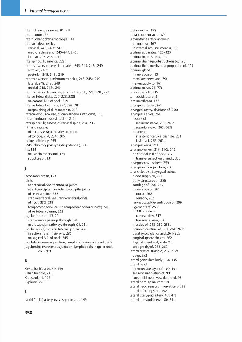
8/15/2019 Head and Neck Anatomy for Dental Medicine - Thieme; (January 26, 2010)
http://slidepdf.com/reader/full/head-and-neck-anatomy-for-dental-medicine-thieme-january-26-2010 371/384
Internal laryngeal nerve, 91, 91t
Interneurons, 55
Internuclear ophthalmoplegia, 141
Interspinales muscles
cervical, 245, 246t, 247
erector spinae and, 246–247, 246t
lumbar, 245, 246t, 247
Interspinous ligaments, 228
Intertransversarii cervicis muscles, 245, 248, 248t, 249
anterior, 248t
posterior, 248, 248t, 249
Intertransversarii lumborum muscles, 248, 248t, 249
lateral, 248, 248t, 249
medial, 248, 248t, 249
Intertransverse ligaments, of vertebral arch, 228, 228t, 229
Intervertebral disks, 226, 228, 228t
on coronal MRI of neck, 319
Intervertebral foramina, 290, 292, 297
outpouching of dura mater in, 298
Intracavernous course, of cranial nerves into orbit, 118
Intramembranous ossification, 2, 2tIntraspinous ligament, of cervical spine, 234, 235
Intrinsic muscles
of back. See Back muscles, intrinsic
of tongue, 204, 204t, 205
Iodine deficiency, 265
IPSP (inhibitory postsynaptic potential), 306
Iris, 124
ocular chambers and, 130
structure of, 131
J
Jacobson’s organ, 153
Jointsatlantoaxial. See Atlantoaxial joints
atlanto-occipital. See Atlanto-occipital joints
of cervical spine, 232
craniovertebral.See Craniovertebral joints
of neck, 232–235
temporomandibular.See Temporomandibular joint (TMJ)
of vertebral column, 232
Jugular foramen, 13, 20
cranial nerve passage through, 67t
neurovascular pathways through, 94, 95t
Jugular vein(s). See also Internal jugular vein
infection transmission via, 286
on sagittal MRI of neck, 345 Jugulofacial venous junction, lymphatic drainage in neck, 269
Jugulosubclavian venous junction, lymphatic drainage in neck,
268–269
K
Kiesselbach’s area, 49, 149
Killian triangle, 215
Krause gland, 122
Kyphosis, 226
L
Labial (facial) artery, nasal septum and, 149
Labial creases, 178
Labial tooth surface, 180
Labyrinthine artery and veins
of inner ear, 167
in internal acoustic meatus, 165
Lacrimal apparatus, 122–123
Lacrimal bone, 5, 108, 142
Lacrimal drainage, obstructions to, 123
Lacrimal fluid, mechanical propulsion of, 123
Lacrimal gland
innervation of, 85
maxillary nerve and, 79t
nerve supply to, 161
Lacrimal nerve, 76, 77t
Laimer triangle, 215
Lambdoid suture, 8
Lamina cribrosa, 133
Laryngeal arteries, 261
Laryngeal cavity, divisions of, 260t
Laryngeal nerves, 261
lesions of recurrent nerve, 263, 263t
superior nerve, 263, 263t
recurrent
in anterior cervical triangle, 281
lesions of, 263, 263t
Laryngeal veins, 261
Laryngopharynx, 216, 216t, 313
on coronal MRI of neck, 317
in transverse section of neck, 330
Laryngoscopy, indirect, 259
Laryngotracheal junction, 256
Larynx. See also Laryngeal entries
blood supply to, 261
bony structures of, 256cartilage of, 256–257
innervation of, 261
motor, 262
sensory, 262
laryngoscopic examination of, 259
ligaments of, 256
on MRIs of neck
coronal view, 317
transverse view, 336
muscles of, 258–259, 258t
neurovasculature of, 260–261, 260t
parathyroid glands and, 264–265
surgical approaches to, 262thyroid gland and, 264–265
topography of, 262–263
Lateral cervical triangle, 272, 272t
deep, 283
Lateral geniculate body, 134, 135
Lateral head
intermediate layer of, 100–101
sensory innervation of, 99
superficial neurovasculature of, 98
Lateral horn, spinal cord, 292
Lateral neck, sensory innervation of, 99
Lateral olfactory stria, 152
Lateral pterygoid artery, 45t, 47t
Lateral pterygoid nerve, 80, 81t
358
I Internal laryngeal nerve
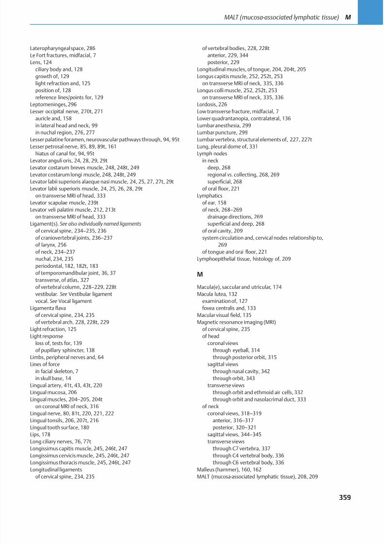
8/15/2019 Head and Neck Anatomy for Dental Medicine - Thieme; (January 26, 2010)
http://slidepdf.com/reader/full/head-and-neck-anatomy-for-dental-medicine-thieme-january-26-2010 372/384
Lateropharyngeal space, 286
Le Fort fractures, midfacial, 7
Lens, 124
ciliary body and, 128
growth of, 129
light refraction and, 125
position of, 128
reference lines/points for, 129
Leptomeninges,296
Lesser occipital nerve, 270t, 271
auricle and, 158
in lateral head and neck, 99
in nuchal region, 276, 277
Lesser palatine foramen, neurovascular pathways through, 94, 95t
Lesser petrosal nerve, 85, 89, 89t, 161
hiatus of canal for, 94, 95t
Levator anguli oris, 24, 28, 29, 29t
Levator costarum breves muscle, 248, 248t, 249
Levator costarum longi muscle, 248, 248t, 249
Levator labii superioris alaeque nasi muscle, 24, 25, 27, 27t, 29t
Levator labii superioris muscle, 24, 25, 26, 28, 29ton transverse MRI of head, 333
Levator scapulae muscle, 239t
Levator veli palatini muscle, 212, 213t
on transverse MRI of head, 333
Ligament(s). See also individually named ligaments
of cervical spine, 234–235, 236
of craniovertebral joints, 236–237
of larynx, 256
of neck, 234–237
nuchal, 234, 235
periodontal, 182, 182t, 183
of temporomandibular joint, 36, 37
transverse, of atlas, 327
of vertebral column, 228–229, 228tvestibular. See Vestibular ligament
vocal. See Vocal ligament
Ligamentaflava
of cervical spine, 234, 235
of vertebral arch, 228, 228t, 229
Light refraction, 125
Light response
loss of, tests for, 139
of pupillary sphincter, 138
Limbs, peripheral nerves and, 64
Lines of force
in facial skeleton, 7
in skull base, 14Lingual artery, 41t, 43, 43t, 220
Lingual mucosa, 206
Lingual muscles, 204–205, 204t
on coronal MRI of neck, 316
Lingual nerve, 80, 81t, 220, 221, 222
Lingual tonsils, 206, 207t, 216
Lingual tooth surface, 180
Lips, 178
Long ciliary nerves, 76, 77t
Longissimus capitis muscle, 245, 246t, 247
Longissimus cervicis muscle, 245, 246t, 247
Longissimus thoracis muscle, 245, 246t, 247
Longitudinal ligaments
of cervical spine, 234, 235
of vertebral bodies, 228, 228t
anterior, 229, 344
posterior, 229
Longitudinal muscles, of tongue, 204, 204t, 205
Longus capitis muscle, 252, 252t, 253
on transverse MRI of neck, 335, 336
Longus colli muscle, 252, 252t, 253
on transverse MRI of neck, 335, 336
Lordosis, 226
Low transverse fracture, midfacial, 7
Lower quadrantanopia, contralateral, 136
Lumbar anesthesia, 299
Lumbar puncture, 299
Lumbar vertebra, structural elements of, 227, 227t
Lung, pleural dome of, 331
Lymph nodes
in neck
deep, 268
regional vs. collecting, 268, 269
superficial, 268
of oral floor, 221Lymphatics
of ear, 158
of neck, 268–269
drainage directions, 269
superficial and deep, 268
of oral cavity, 209
system circulation and, cervical nodes relationship to,
269
of tongue and oral floor, 221
Lymphoepithelial tissue, histology of, 209
M
Macula(e), saccular and utricular, 174Macula lutea, 132
examination of, 127
fovea centralis and, 133
Macular visual field, 135
Magnetic resonance imaging (MRI)
of cervical spine, 235
of head
coronal views
through eyeball, 314
through posterior orbit, 315
sagittal views
through nasal cavity, 342
through orbit, 343transverse views
through orbit and ethmoid air cells,332
through orbit and nasolacrimal duct, 333
of neck
coronal views, 318–319
anterior, 316–317
posterior, 320–321
sagittal views, 344–345
transverse views
through C7 vertebra, 337
through C4 vertebral body, 336
through C6 vertebral body, 336
Malleus (hammer), 160, 162
MALT (mucosa-associated lymphatic tissue), 208, 209
359
MALT (mucosa-associated lymphatic tissue) M
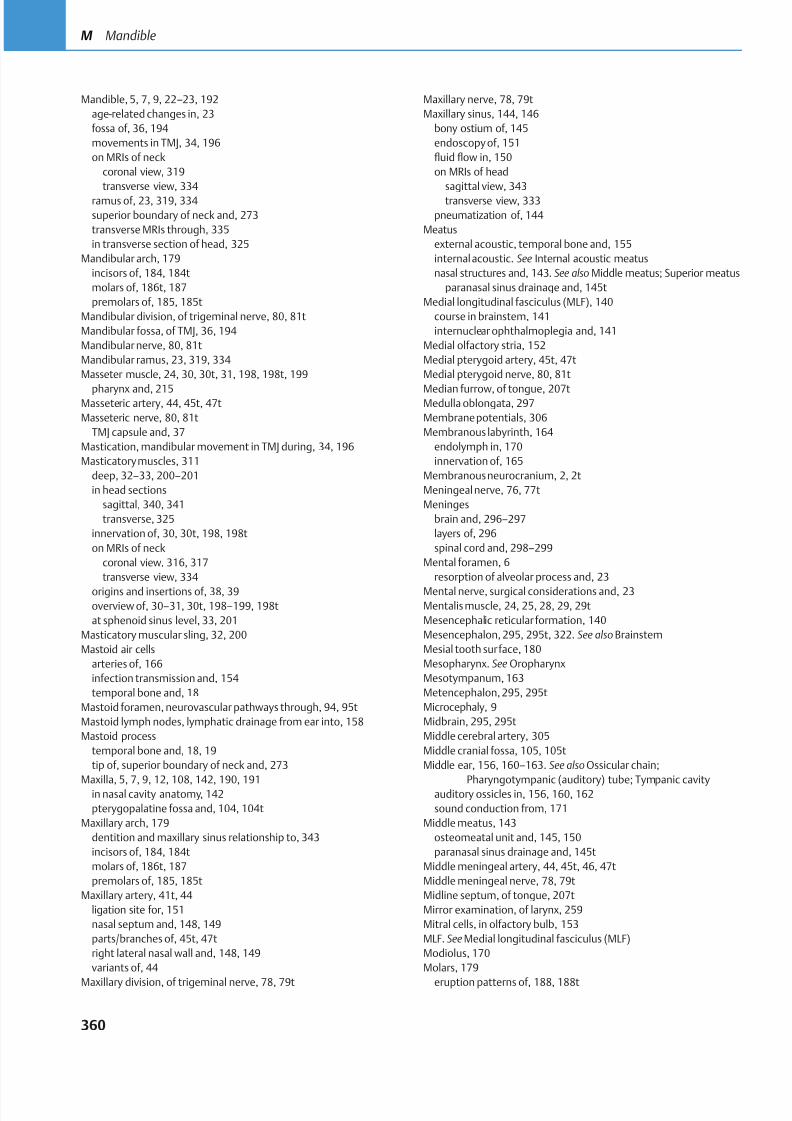
8/15/2019 Head and Neck Anatomy for Dental Medicine - Thieme; (January 26, 2010)
http://slidepdf.com/reader/full/head-and-neck-anatomy-for-dental-medicine-thieme-january-26-2010 373/384
Mandible, 5, 7, 9, 22–23, 192
age-related changes in, 23
fossa of, 36, 194
movements in TMJ, 34, 196
on MRIs of neck
coronal view, 319
transverse view, 334
ramus of, 23, 319, 334
superior boundary of neck and, 273
transverse MRIs through, 335
in transverse section of head, 325
Mandibular arch, 179
incisors of, 184, 184t
molars of, 186t, 187
premolars of, 185, 185t
Mandibular division, of trigeminal nerve, 80, 81t
Mandibular fossa, of TMJ, 36, 194
Mandibular nerve, 80, 81t
Mandibular ramus, 23, 319, 334
Masseter muscle, 24, 30, 30t, 31, 198, 198t, 199
pharynx and, 215Masseteric artery, 44, 45t, 47t
Masseteric nerve, 80, 81t
TMJ capsule and, 37
Mastication, mandibular movement in TMJ during, 34, 196
Masticatory muscles, 311
deep, 32–33, 200–201
in head sections
sagittal, 340, 341
transverse, 325
innervation of, 30, 30t, 198, 198t
on MRIs of neck
coronal view, 316, 317
transverse view, 334
origins and insertions of, 38, 39overview of, 30–31, 30t, 198–199, 198t
at sphenoid sinus level, 33, 201
Masticatory muscular sling, 32, 200
Mastoid air cells
arteries of, 166
infection transmission and, 154
temporal bone and, 18
Mastoid foramen, neurovascular pathways through, 94, 95t
Mastoid lymph nodes, lymphatic drainage from ear into, 158
Mastoid process
temporal bone and, 18, 19
tip of, superior boundary of neck and, 273
Maxilla, 5, 7, 9, 12, 108, 142, 190, 191in nasal cavity anatomy, 142
pterygopalatine fossa and, 104, 104t
Maxillary arch, 179
dentition and maxillary sinus relationship to, 343
incisors of, 184, 184t
molars of, 186t, 187
premolars of, 185, 185t
Maxillary artery, 41t, 44
ligation site for, 151
nasal septum and, 148, 149
parts/branches of, 45t, 47t
right lateral nasal wall and, 148, 149
variants of, 44
Maxillary division, of trigeminal nerve, 78, 79t
Maxillary nerve, 78, 79t
Maxillary sinus, 144, 146
bony ostium of, 145
endoscopy of, 151
fluid flow in, 150
on MRIs of head
sagittal view, 343
transverse view, 333
pneumatization of, 144
Meatus
external acoustic, temporal bone and, 155
internal acoustic. See Internal acoustic meatus
nasal structures and, 143. See also Middle meatus; Superior meatus
paranasal sinus drainage and, 145t
Medial longitudinal fasciculus (MLF), 140
course in brainstem, 141
internuclear ophthalmoplegia and, 141
Medial olfactory stria, 152
Medial pterygoid artery, 45t, 47t
Medial pterygoid nerve, 80, 81t
Median furrow, of tongue, 207tMedulla oblongata, 297
Membrane potentials, 306
Membranous labyrinth, 164
endolymph in, 170
innervation of, 165
Membranous neurocranium, 2, 2t
Meningeal nerve, 76, 77t
Meninges
brain and, 296–297
layers of, 296
spinal cord and, 298–299
Mental foramen, 6
resorption of alveolar process and, 23
Mental nerve, surgical considerations and, 23Mentalis muscle, 24, 25, 28, 29, 29t
Mesencephalic reticular formation, 140
Mesencephalon, 295, 295t, 322. See also Brainstem
Mesial tooth surface, 180
Mesopharynx. See Oropharynx
Mesotympanum, 163
Metencephalon,295, 295t
Microcephaly, 9
Midbrain, 295, 295t
Middle cerebral artery, 305
Middle cranial fossa, 105, 105t
Middle ear, 156, 160–163. See also Ossicular chain;
Pharyngotympanic (auditory) tube; Tympanic cavityauditory ossicles in, 156, 160, 162
sound conduction from, 171
Middle meatus, 143
osteomeatal unit and, 145, 150
paranasal sinus drainage and, 145t
Middle meningeal artery, 44, 45t, 46, 47t
Middle meningeal nerve, 78, 79t
Midline septum, of tongue, 207t
Mirror examination, of larynx, 259
Mitral cells, in olfactory bulb, 153
MLF. See Medial longitudinal fasciculus (MLF)
Modiolus, 170
Molars, 179
eruption patterns of, 188, 188t
360
M Mandible
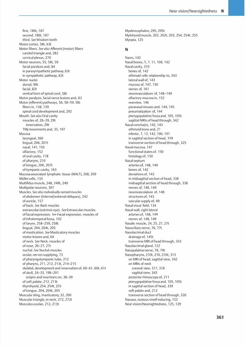
8/15/2019 Head and Neck Anatomy for Dental Medicine - Thieme; (January 26, 2010)
http://slidepdf.com/reader/full/head-and-neck-anatomy-for-dental-medicine-thieme-january-26-2010 374/384
first, 186t, 187
second, 186t, 187
third. See Wisdom teeth
Motor cortex, 58t, 63t
Motor fibers. See also Aff erent (motor) fibers
carotid triangle and, 282
cervical plexus, 270
Motor neurons, 55, 58t, 59
facial paralysis and, 84
in parasympathetic pathway,63t
in sympathetic pathway, 62t
Motor nuclei
dorsal, 90t
facial, 82t
ventral horn of spinal cord, 58t
Motor paralysis, facial nerve lesions and, 83
Motor (eff erent) pathways, 56, 58–59, 58t
fibers in, 138, 139
spinal cord development and, 292
Mouth. See also Oral cavity
muscles of, 28–29, 29tinnervation, 29t
TMJ movements and, 35, 197
Mucosa
laryngeal, 260
lingual, 206, 207t
nasal, 147, 150
olfactory, 152
of oral cavity, 178
of pharynx, 210
of tongue, 206, 207t
of tympanic cavity, 163
Mucosa-associated lymphatic tissue (MALT), 208, 209
Müller cells, 133
Multifidus muscle, 248, 248t, 249Multipolar neurons, 307
Muscles. See also individually named muscles
of abdomen (internal/external obliques), 242
of auricle, 157
of back. See Back muscles
extraocular (extrinsic eye). See Extraocular muscles
of facial expression. See Facial expression, muscles of
of infratemporal fossa, 102
of larynx, 258–259, 258t
lingual, 204, 204t, 205
of mastication. See Masticatory muscles
motor lesions and, 64
of neck. See Neck, muscles of of nose, 26–27, 27t
nuchal. See Nuchal muscles
ocular, nerves supplying, 73
of pharyngotympanic tube, 212
of pharynx, 211, 212, 213t, 214–215
skeletal, development and innervation of, 60–61, 60t, 61t
of skull, 24–33, 198–201
origins and insertions on, 38–39
of soft palate, 212, 213t
thyrohyoid, 254, 254t, 255
of tongue, 204, 204t, 205
Muscular sling, masticatory, 32, 200
Muscular triangle, in neck, 272, 272t
Musculus uvulae, 212, 213t
Myelencephalon,295, 295t
Mylohyoid muscle, 202, 202t, 203, 254, 254t, 255
Myopia, 125
N
Nares, 142
Nasal bones, 5, 7, 11, 108, 142
Nasal cavity, 310
bones of, 142
ethmoid cells relationship to, 343
lateral wall of, 143
mucosa of, 147, 150
nerves of, 161
neurovasculature of, 148–149
olfactory mucosa in, 152
overview, 146
paranasal sinuses and, 144, 145
pneumatization of, 144
pterygopalatine fossa and, 105, 105t
sagittal MRIs of head through, 342Nasal concha(e), 142, 143
ethmoid bone and, 21
inferior, 7, 12, 142, 190, 191
in sagittal section of head, 339
transverse section of head through, 325
Nasal mucosa, 147
functional states of, 150
histology of, 150
Nasal septum
arteries of, 148, 149
bones of, 142
deviations of, 143
in midsagittal section of head, 338
midsagittal section of head through, 338nerves of, 148, 149
neurovasculature of, 148
structures of, 143
vascular supply of, 49
Nasal visual field, 134
Nasal wall, right lateral
arteries of, 148, 149
nerves of, 148, 149
Nasalis muscle, 24, 25, 27, 27t
Nasociliary nerve, 76, 77t
Nasolacrimal duct
drainage of, 145t
transverse MRI of head through, 333Nasolacrimal gland, 122
Nasopalatine nerve, 78, 79t
Nasopharynx, 210t, 216, 216t, 313
on MRI of head, sagittal view, 342
on MRIs of neck
coronal view, 317, 318
sagittal view, 343
posterior rhinoscopy of, 211
pterygopalatine fossa and, 105, 105t
in sagittal section of head, 339
soft palate and, 212
transverse section of head through, 326
Nausea, noxious smell inducing, 152
Near vision/Nearsightedness, 125, 129
361
Near vision/Nearsightedness N
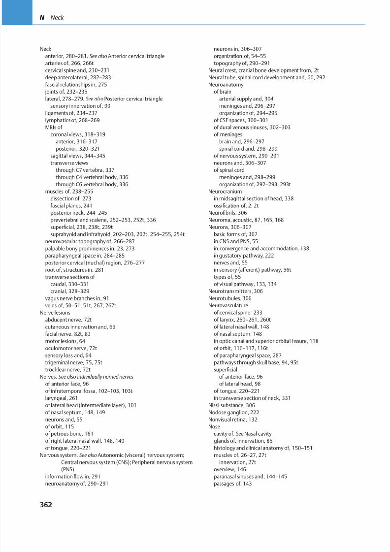
8/15/2019 Head and Neck Anatomy for Dental Medicine - Thieme; (January 26, 2010)
http://slidepdf.com/reader/full/head-and-neck-anatomy-for-dental-medicine-thieme-january-26-2010 375/384
Neck
anterior, 280–281. See also Anterior cervical triangle
arteries of, 266, 266t
cervical spine and, 230–231
deep anterolateral, 282–283
fascial relationships in, 275
joints of, 232–235
lateral, 278–279. See also Posterior cervical triangle
sensory innervation of, 99
ligaments of, 234–237
lymphatics of, 268–269
MRIs of
coronal views, 318–319
anterior, 316–317
posterior, 320–321
sagittal views, 344–345
transverse views
through C7 vertebra, 337
through C4 vertebral body, 336
through C6 vertebral body, 336
muscles of, 238–255dissection of, 273
fascial planes, 241
posterior neck, 244–245
prevertebral and scalene, 252–253, 252t, 336
superficial, 238, 238t, 239t
suprahyoid and infrahyoid, 202–203, 202t, 254–255, 254t
neurovascular topography of, 266–287
palpable bony prominences in, 23, 273
parapharyngeal space in, 284–285
posterior cervical (nuchal) region, 276–277
root of, structures in, 281
transverse sections of
caudal, 330–331
cranial, 328–329vagus nerve branches in, 91
veins of, 50–51, 51t, 267, 267t
Nerve lesions
abducent nerve, 72t
cutaneous innervation and, 65
facial nerve, 82t, 83
motor lesions, 64
oculomotor nerve, 72t
sensory loss and, 64
trigeminal nerve, 75, 75t
trochlear nerve, 72t
Nerves. See also individually named nerves
of anterior face, 96of infratemporal fossa, 102–103, 103t
laryngeal, 261
of lateral head (intermediate layer), 101
of nasal septum, 148, 149
neurons and, 55
of orbit, 115
of petrous bone, 161
of right lateral nasal wall, 148, 149
of tongue, 220–221
Nervous system. See also Autonomic (visceral) nervous system;
Central nervous system (CNS); Peripheral nervous system
(PNS)
informationflow in, 291
neuroanatomy of, 290–291
neurons in, 306–307
organization of, 54–55
topography of, 290–291
Neural crest, cranial bone development from, 2t
Neural tube, spinal cord development and, 60, 292
Neuroanatomy
of brain
arterial supply and, 304
meninges and, 296–297
organization of, 294–295
of CSF spaces, 300–301
of dural venous sinuses, 302–303
of meninges
brain and, 296–297
spinal cord and, 298–299
of nervous system, 290–291
neurons and, 306–307
of spinal cord
meninges and, 298–299
organization of, 292–293, 293t
Neurocraniumin midsagittal section of head, 338
ossification of, 2, 2t
Neurofibrils, 306
Neuroma, acoustic, 87, 165, 168
Neurons, 306–307
basic forms of, 307
in CNS and PNS, 55
in convergence and accommodation, 138
in gustatory pathway, 222
nerves and, 55
in sensory (aff erent) pathway, 56t
types of, 55
of visual pathway, 133, 134
Neurotransmitters, 306Neurotubules, 306
Neurovasculature
of cervical spine, 233
of larynx, 260–261, 260t
of lateral nasal wall, 148
of nasal septum, 148
in optic canal and superior orbital fissure, 118
of orbit, 116–117, 116t
of parapharyngeal space, 287
pathways through skull base, 94, 95t
superficial
of anterior face, 96
of lateral head, 98of tongue, 220–221
in transverse section of neck, 331
Nissl substance, 306
Nodose ganglion, 222
Nonvisual retina, 132
Nose
cavity of. See Nasal cavity
glands of, innervation, 85
histology and clinical anatomy of, 150–151
muscles of, 26–27, 27t
innervation, 27t
overview, 146
paranasal sinuses and, 144–145
passages of, 143
362
N Neck
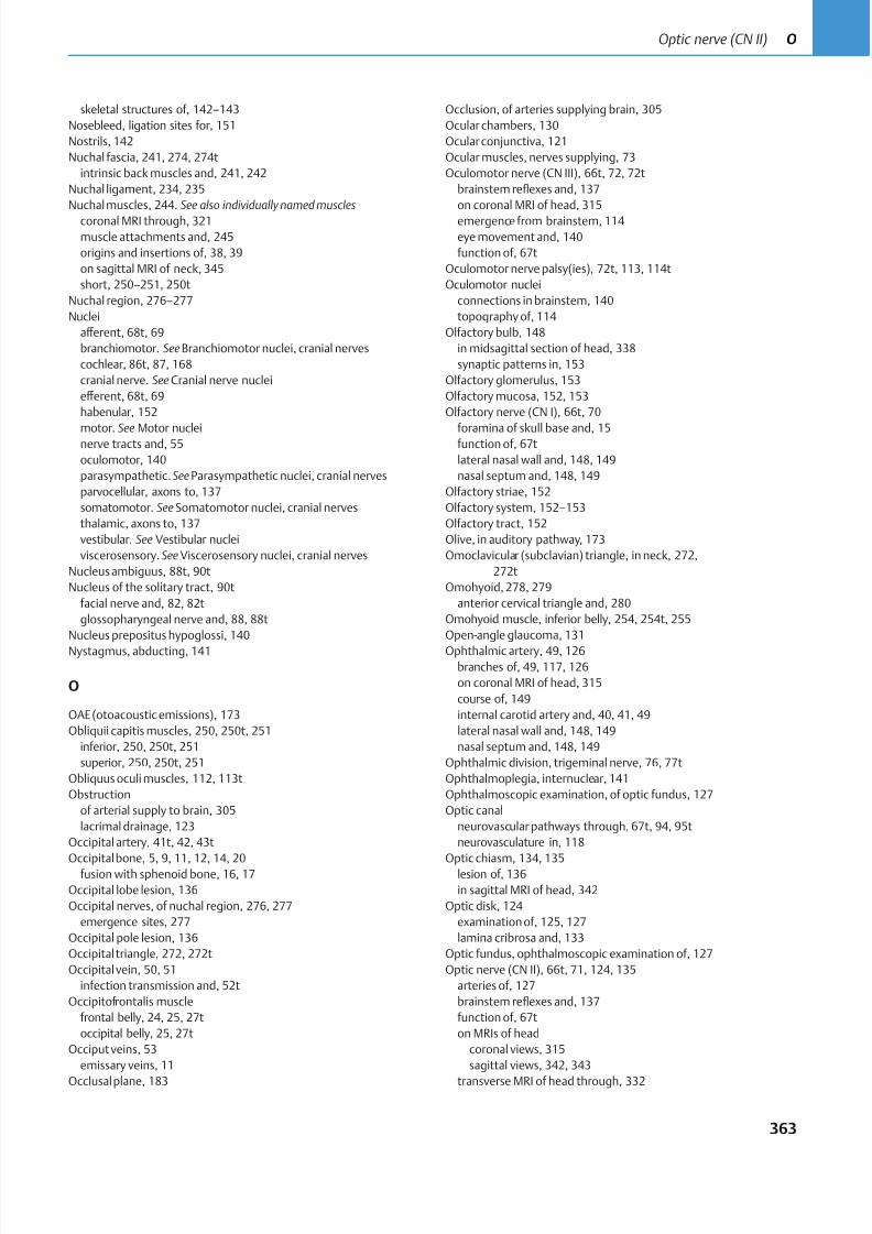
8/15/2019 Head and Neck Anatomy for Dental Medicine - Thieme; (January 26, 2010)
http://slidepdf.com/reader/full/head-and-neck-anatomy-for-dental-medicine-thieme-january-26-2010 376/384
skeletal structures of, 142–143
Nosebleed, ligation sites for, 151
Nostrils, 142
Nuchal fascia, 241, 274, 274t
intrinsic back muscles and, 241, 242
Nuchal ligament, 234, 235
Nuchal muscles, 244. See also individually named muscles
coronal MRI through, 321
muscle attachments and, 245
origins and insertions of, 38, 39
on sagittal MRI of neck, 345
short, 250–251, 250t
Nuchal region, 276–277
Nuclei
aff erent, 68t, 69
branchiomotor. See Branchiomotor nuclei, cranial nerves
cochlear, 86t, 87, 168
cranial nerve. See Cranial nerve nuclei
eff erent, 68t, 69
habenular, 152
motor. See Motor nucleinerve tracts and, 55
oculomotor, 140
parasympathetic.See Parasympathetic nuclei, cranial nerves
parvocellular, axons to, 137
somatomotor. See Somatomotor nuclei, cranial nerves
thalamic, axons to, 137
vestibular. See Vestibular nuclei
viscerosensory. See Viscerosensory nuclei, cranial nerves
Nucleus ambiguus, 88t, 90t
Nucleus of the solitary tract, 90t
facial nerve and, 82, 82t
glossopharyngeal nerve and, 88, 88t
Nucleus prepositus hypoglossi, 140
Nystagmus, abducting, 141
O
OAE (otoacoustic emissions), 173
Obliquii capitis muscles, 250, 250t, 251
inferior, 250, 250t, 251
superior, 250, 250t, 251
Obliquus oculi muscles, 112, 113t
Obstruction
of arterial supply to brain, 305
lacrimal drainage, 123
Occipital artery, 41t, 42, 43t
Occipital bone, 5, 9, 11, 12, 14, 20fusion with sphenoid bone, 16, 17
Occipital lobe lesion, 136
Occipital nerves, of nuchal region, 276, 277
emergence sites, 277
Occipital pole lesion, 136
Occipital triangle, 272, 272t
Occipital vein, 50, 51
infection transmission and, 52t
Occipitofrontalis muscle
frontal belly, 24, 25, 27t
occipital belly, 25, 27t
Occiput veins, 53
emissary veins, 11
Occlusal plane, 183
Occlusion, of arteries supplying brain, 305
Ocular chambers, 130
Ocular conjunctiva, 121
Ocular muscles, nerves supplying, 73
Oculomotor nerve (CN III), 66t, 72, 72t
brainstem reflexes and, 137
on coronal MRI of head, 315
emergence from brainstem, 114
eye movement and, 140
function of, 67t
Oculomotor nerve palsy(ies), 72t, 113, 114t
Oculomotor nuclei
connections in brainstem, 140
topography of, 114
Olfactory bulb, 148
in midsagittal section of head, 338
synaptic patterns in, 153
Olfactory glomerulus, 153
Olfactory mucosa, 152, 153
Olfactory nerve (CN I), 66t, 70
foramina of skull base and, 15function of, 67t
lateral nasal wall and, 148, 149
nasal septum and, 148, 149
Olfactory striae, 152
Olfactory system, 152–153
Olfactory tract, 152
Olive, in auditory pathway, 173
Omoclavicular (subclavian) triangle, in neck, 272,
272t
Omohyoid, 278, 279
anterior cervical triangle and, 280
Omohyoid muscle, inferior belly, 254, 254t, 255
Open-angle glaucoma, 131
Ophthalmic artery, 49, 126branches of, 49, 117, 126
on coronal MRI of head, 315
course of, 149
internal carotid artery and, 40, 41, 49
lateral nasal wall and, 148, 149
nasal septum and, 148, 149
Ophthalmic division, trigeminal nerve, 76, 77t
Ophthalmoplegia, internuclear, 141
Ophthalmoscopic examination, of optic fundus, 127
Optic canal
neurovascular pathways through, 67t, 94, 95t
neurovasculature in, 118
Optic chiasm, 134, 135lesion of, 136
in sagittal MRI of head, 342
Optic disk, 124
examination of, 125, 127
lamina cribrosa and, 133
Optic fundus, ophthalmoscopic examination of, 127
Optic nerve (CN II), 66t, 71, 124, 135
arteries of, 127
brainstem reflexes and, 137
function of, 67t
on MRIs of head
coronal views, 315
sagittal views, 342, 343
transverse MRI of head through, 332
363
Optic nerve (CN II) O
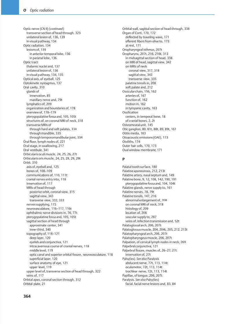
8/15/2019 Head and Neck Anatomy for Dental Medicine - Thieme; (January 26, 2010)
http://slidepdf.com/reader/full/head-and-neck-anatomy-for-dental-medicine-thieme-january-26-2010 377/384
Optic nerve (CN II) (continued )
transverse section of head through, 323
unilateral lesion of, 136, 139
in visual pathway, 134
Optic radiation, 134
lesions of, 139
in anterior temporal lobe, 136
in parietal lobe, 136
Optic tract
thalamic nuclei and, 137
unilateral lesion of, 136
in visual pathway, 134, 135
Optical axis, of eyeball, 125
Optokinetic nystagmus, 137
Oral cavity, 310
glands of
innervation, 85
maxillary nerve and, 79t
lymphatics of, 209
organization and boundaries of, 178
overview of, 178–179pterygopalatine fossa and, 105, 105t
structures of, on coronal MRI of neck, 318
transverse MRIs of
through hard and soft palates, 334
through mandible, 335
through temporomandibular joint, 334
Oral floor, lymph nodes of, 221
Oral stage, in swallowing, 217
Oral vestibule, 341
Orbicularis oculi muscle, 24, 25, 26, 27t
Orbicularis oris muscle, 24, 25, 28, 29, 29t
Orbit, 310
axis of, eyeball and, 125
bones of, 108–109communications of, 110, 111t
cranial nerves entry into, 118
innervation of, 117
MRIs of head through
posterior orbit, coronal view, 315
sagittal view, 343
transverse view, 332, 333
nerves supplying, 115
neurovasculature, 116–117, 116t
ophthalmic nerve divisions in, 76, 77t
pterygopalatine fossa and, 105, 105t
sagittal section of head through
approximate center, 341inner third, 340
topography of, 118–121
deep layer, 120
eyelids and conjunctiva, 121
intracavernous course of cranial nerves, 118
middle level, 119
optic canal and superior orbital fissure, neurovasculature, 118
superficial layer, 120
surface anatomy of eye, 121
upper level, 119
upper level of, transverse section of head through, 322
veins of, 117
Orbital apex, coronal section through, 312
Orbital plate, 21
Orbital wall, sagittal section of head through, 338
Organ of Corti, 170, 172
deflected by traveling wave, 171
eff erent fibers from olive to, 173
at rest, 171
Oropharyngeal isthmus, 207t
Oropharynx, 207t, 216, 216t, 313
in midsagittal section of head, 338
on MRI of head, sagittal view, 342
on MRIs of neck
coronal view, 317, 318
sagittal view, 343
transverse view, 335
palatine tonsils in, 208
soft palate and, 212
Ossicular chain, 156, 162
arteries of, 167
function of, 162
motion in, 162
in tympanic cavity, 163
Ossificationcenters, in temporal bone, 18
of cranial bones, 2, 2t
Osteomeatal unit, 145
Otic ganglion, 80, 81t, 88t, 89, 89t, 161
Otitis media, 163
Otoacoustic emissions (OAE), 173
Otoliths, 174
Outer hair cells, 170, 173
Oval window membrane, 171
P
Palatal tooth surface, 180
Palatine aponeurosis, 212, 213tPalatine artery, nasal septum and, 149
Palatine bone, 9, 12, 108, 142, 190, 191
pterygopalatine fossa and, 104, 104t
Palatine glands, nerve supply to, 161
Palatine nerves, 78, 79t
Palatine tonsils, 147, 216
abnormal enlargement of, 208
on coronal MRI of neck, 318
histology of, 209
location of, 208
vascular supply to, 287
veins of, infection transmission and, 52t
Palatoglossal arch, 206, 207tPalatoglossus muscle, 204, 204t, 205, 212, 213t
Palatopharyngeal arch, 206, 207t
Palatopharyngeus muscle, 206, 207t
Palpation, of cervical lymph nodes in neck, 269
Palpebral conjunctiva, 121
Palpebral fissure, muscles of, 26–27, 27t
innervation of, 27t
Palsy(ies). See also Paralysis
abducent nerve, 72t, 113, 114t
oculomotor, 72t, 113, 114t
trochlear nerve, 72t, 113, 114t
Papillae, of tongue, 206, 207t
Paralysis. See also Palsy(ies)
facial, facial nerve lesions and, 83, 84
364
O Optic radiation
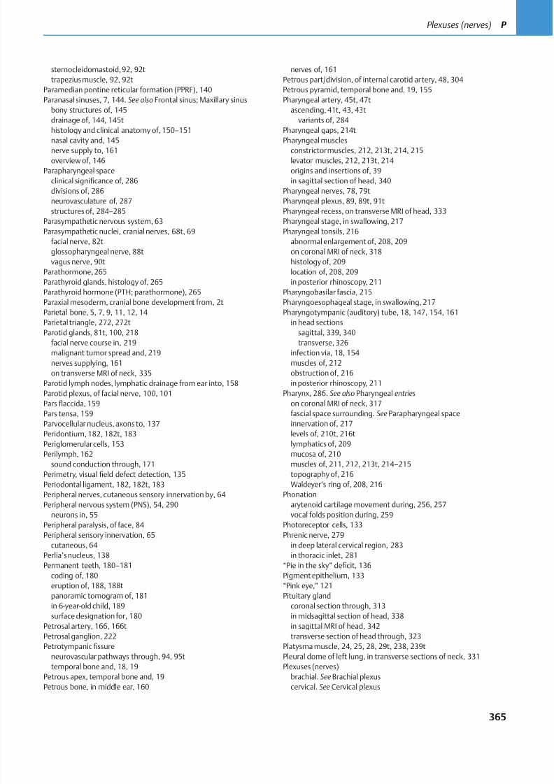
8/15/2019 Head and Neck Anatomy for Dental Medicine - Thieme; (January 26, 2010)
http://slidepdf.com/reader/full/head-and-neck-anatomy-for-dental-medicine-thieme-january-26-2010 378/384
sternocleidomastoid,92, 92t
trapezius muscle, 92, 92t
Paramedian pontine reticular formation (PPRF), 140
Paranasal sinuses, 7, 144. See also Frontal sinus; Maxillary sinus
bony structures of, 145
drainage of, 144, 145t
histology and clinical anatomy of, 150–151
nasal cavity and, 145
nerve supply to, 161
overview of, 146
Parapharyngeal space
clinical significance of, 286
divisions of, 286
neurovasculature of, 287
structures of, 284–285
Parasympathetic nervous system, 63
Parasympathetic nuclei, cranial nerves, 68t, 69
facial nerve, 82t
glossopharyngeal nerve, 88t
vagus nerve, 90t
Parathormone, 265Parathyroid glands, histology of, 265
Parathyroid hormone (PTH; parathormone), 265
Paraxial mesoderm, cranial bone development from, 2t
Parietal bone, 5, 7, 9, 11, 12, 14
Parietal triangle, 272, 272t
Parotid glands, 81t, 100, 218
facial nerve course in, 219
malignant tumor spread and, 219
nerves supplying, 161
on transverse MRI of neck, 335
Parotid lymph nodes, lymphatic drainage from ear into, 158
Parotid plexus, of facial nerve, 100, 101
Pars flaccida, 159
Pars tensa, 159Parvocellular nucleus, axons to, 137
Peridontium, 182, 182t, 183
Periglomerular cells, 153
Perilymph, 162
sound conduction through, 171
Perimetry, visual field defect detection, 135
Periodontal ligament, 182, 182t, 183
Peripheral nerves, cutaneous sensory innervation by, 64
Peripheral nervous system (PNS), 54, 290
neurons in, 55
Peripheral paralysis, of face, 84
Peripheral sensory innervation, 65
cutaneous, 64Perlia’s nucleus, 138
Permanent teeth, 180–181
coding of, 180
eruption of, 188, 188t
panoramic tomogram of, 181
in 6-year-old child, 189
surface designation for, 180
Petrosal artery, 166, 166t
Petrosal ganglion, 222
Petrotympanicfissure
neurovascular pathways through, 94, 95t
temporal bone and, 18, 19
Petrous apex, temporal bone and, 19
Petrous bone, in middle ear, 160
nerves of, 161
Petrous part/division, of internal carotid artery, 48, 304
Petrous pyramid, temporal bone and, 19, 155
Pharyngeal artery, 45t, 47t
ascending, 41t, 43, 43t
variants of, 284
Pharyngeal gaps, 214t
Pharyngeal muscles
constrictor muscles, 212, 213t, 214, 215
levator muscles, 212, 213t, 214
origins and insertions of, 39
in sagittal section of head, 340
Pharyngeal nerves, 78, 79t
Pharyngeal plexus, 89, 89t, 91t
Pharyngeal recess, on transverse MRI of head, 333
Pharyngeal stage, in swallowing, 217
Pharyngeal tonsils, 216
abnormal enlargement of, 208, 209
on coronal MRI of neck, 318
histology of, 209
location of, 208, 209in posterior rhinoscopy, 211
Pharyngobasilar fascia, 215
Pharyngoesophageal stage, in swallowing, 217
Pharyngotympanic (auditory) tube, 18, 147, 154, 161
in head sections
sagittal, 339, 340
transverse, 326
infection via, 18, 154
muscles of, 212
obstruction of, 216
in posterior rhinoscopy, 211
Pharynx, 286. See also Pharyngeal entries
on coronal MRI of neck, 317
fascial space surrounding. See Parapharyngeal spaceinnervation of, 217
levels of, 210t, 216t
lymphatics of, 209
mucosa of, 210
muscles of, 211, 212, 213t, 214–215
topography of, 216
Waldeyer’s ring of, 208, 216
Phonation
arytenoid cartilage movement during, 256, 257
vocal folds position during, 259
Photoreceptor cells, 133
Phrenic nerve, 279
in deep lateral cervical region, 283in thoracic inlet, 281
“Pie in the sky” deficit, 136
Pigment epithelium, 133
“Pink eye,” 121
Pituitary gland
coronal section through, 313
in midsagittal section of head, 338
in sagittal MRI of head, 342
transverse section of head through, 323
Platysma muscle, 24, 25, 28, 29t, 238, 239t
Pleural dome of left lung, in transverse sections of neck, 331
Plexuses (nerves)
brachial. See Brachial plexus
cervical. See Cervical plexus
365
Plexuses (nerves) P
8/15/2019 Head and Neck Anatomy for Dental Medicine - Thieme; (January 26, 2010)
http://slidepdf.com/reader/full/head-and-neck-anatomy-for-dental-medicine-thieme-january-26-2010 379/384
Plexuses (nerves) (continued )
parotid, 100, 101
pharyngeal, 89, 89t, 90t, 217
Plexuses (venous)
basilar, 302
choroid, 301
dural sinus drainage and, 302
external vertebral, infection transmission and, 52t
pterygoid, 53
thyroid, 265
Pneumatization, of paranasal sinuses, 144
PNS. See Peripheral nervous system (PNS)
Pons, 297, 323
Pontocerebellar cistern, in transverse section of head, 325
Posterior auricular arteries, 41t, 42, 43t, 157
Posterior auricular nerve, 84
Posterior auricular vein, 50, 51
infection transmission and, 52t
Posterior cerebral artery, 305
Posterior cervical (nuchal) region, 276–277
Posterior cervical triangledissection of, 278–279
lymph nodes in, 268
Posterior communicating artery, 305
Posterior condylar canal, neurovascular pathways through, 94, 95t
Posterior ethmoid nerve, 76, 77t
Posterior rhinoscopy, 151, 211
Posterior superior alveolar artery, 44, 45t, 47t
Posterior superior nerves
alveolar, 78, 79t
nasal, 78, 79t
Posterior tympanic artery, 166, 166t
Postganglionic neuron
in parasympathetic pathway,63t
in sympathetic pathway, 62tPotential at the axon hillock, 306
PPRF (paramedian pontine reticular formation),140
Preganglionic neuron
in parasympathetic pathway,63t
in sympathetic pathway, 62t
Premolars, 179, 185, 185t
eruption patterns, 188, 188t
Pretectal area, axons to, 137
Pretracheal fascia, 274, 274t, 275
in parapharyngeal space, 284–287
Prevertebral fascia, 274, 274t, 278, 279
cervical, 241
retropharyngeal space and, 286Prevertebral ganglia, 62t
Prevertebral muscles, 252–253, 252t. See also individually named
muscles
origins and insertions of, 39
on transverse MRI of neck, 335, 336
Primary auditory cortex, 172
Procerus muscle, 24, 26, 27t
Prosencephalon, 295, 295t
Pseudounipolar neuron, 55, 57, 307
Pseuodunipolar ganglion cells, 222
Pterygoid arteries, 45t, 47t
Pterygoid canal, 45t, 47t
Pterygoid muscles, lateral and medial, 30, 30t, 32, 198, 198t, 200
Pterygoid plexus, 53
Pterygoid process plates, on transverse MRI of head,333
Pterygopalatine fossa, 16, 17, 104–105
borders of, 104t
communications of, 105, 105t
infratemporal fossa and, 102, 105, 105t
Pterygopalatine ganglion, 79t, 148
facial nerve and, 82t
Pterygopharyngeus muscle, 213t, 214
PTH (parathyroid hormone), 265
Pulvinar of thalamus, axons to, 137
Pupil size, 130
changes in, 130t
Pupillary constriction, 138
Pupillary light reflex, 139
pathway lesions and, 139
Pupillary reflex, 137
Pupillary resistance, 131
Pupillary sphincter light response,138
Purkinje cell, 307
Pyramid fracture, midfacial, 7
Pyramidal cell, 307
Q
Quadrantanopia, contralateral upper and lower, 136
R
Ramus(rami)
of cervical nerves
dorsal, 99, 270, 270t
in nuchal region innervation, 277
ventral, 270
mandibular
angle of mandible and, 23on MRIs of neck
coronal view, 319
transverse view, 334
ventral, of spinal nerves, 290
Rectus capitis muscles, 252, 252t, 253
anterior, 252, 252t, 253
lateral, 252, 252t, 253
posterior, 250, 250t, 251
major, 250, 250t, 251
minor, 250, 250t, 251
in sagittal section of head, 340
Rectus oculi muscles, 112, 113t
inferioron sagittal MRI of head, 343
in sagittal section of head, 340
lateral, in sagittal section of head, 340
in sagittal section of head, 340
superior, on sagittal MRI of head, 343
Recurrent laryngeal nerve, 91, 91t
pharyngeal innervation and, 213t, 217
right, in anterior cervical triangle, 281
in thoracic inlet, 281
Red nucleus, 322
Reference lines/points
of eyeball, 125
of lens, 129
Reflex(es)
366
P Plexuses (venous)
8/15/2019 Head and Neck Anatomy for Dental Medicine - Thieme; (January 26, 2010)
http://slidepdf.com/reader/full/head-and-neck-anatomy-for-dental-medicine-thieme-january-26-2010 380/384
brainstem, 137
pupillary light, 139
salivary, 222
stapedius, 173
Reissner membrane, vestibular, 170
Respiration, position of vocal folds during, 259
Respiratory epithelium, 150
Reticular formation, mesencephalic, 140
Retina, 124, 132–133
layers of, 132
light refraction and, 125
neurons of, 133, 134
nonvisual, 132
structure of, 133
Retinal projection, 135
Retrobulbar space, coronal section through, 311
Retromandibular vein, 50, 51
on transverse MRI of neck, 335
Retropharyngeal space, 286
Retrovisceral/retropharyngeal fascial space, 274, 274t
Rhinoscopy, 151posterior, of nasopharynx, 211
Rhombencephalon, 295, 295t
Rhomboid minor muscle, 239t, 240
Rima glottidis, 260
Rima vestibuli, 260
Risorius muscle, 24, 25, 28, 29, 29t
Rods, 133
Rotational movement, in TMJ, 34, 37, 196
Rotatores brevis muscle, 248, 248t, 249
Rotatores longi muscle, 248, 248t, 249
Round window, 171
S
Saccades, 140
Saccule, 156
macular structure of, 174
Sacrum, structural elements of, 227, 227t
Salivary glands
bimanual examination of, 219
major, 218
minor, 219
Salivation, 219
aff erent impulses and, 222
facial nerve lesions and, 82t, 83
stimulation of, 152
Salpingopharyngeal folds, 208, 209Salpingopharyngeus muscle, 212, 213t
Scaff olding, trigeminal nerve and, 74t
autonomic, 79t
Scala media, 170
Scala tympani, 170
Scala vestibuli, 170
Scalene muscles, 252–253, 252t. See also individually named muscles
on MRIs of neck
sagittal view, 345
transverse view, 336
in transverse sections
of head, 329
of neck, 331
Scalene anterior muscle, 252, 252t, 253
in transverse sections
of head, 252, 252t, 253
of neck, 331
Scalene medius muscle, 252, 252t, 253
on MRIs of neck
sagittal view, 345
transverse view, 336
in transverse sections
of head, 329
of neck, 331
Scalene posterior muscle, 252, 252t, 253
on MRI of neck, sagittal view, 345
in transverse sections
of head, 329
of neck, 331
Scalp, calvaria and, 11
Schlemm, canal of, 124
Schwannoma, vestibular, 87, 165, 168
Sclera, 124
Scoliosis, 226
Scotoma, homonymous hemianopic central,136
Sebaceous glands, in ear, 159
Second molars, 186t, 187
eruption patterns of, 188, 188t
Secondary sensory cells
in auditory pathway, 172
in vestibular system, 176
Segmental (radicular) sensory innervation, 65
Sella turcica, 16, 17
Semicircular canals, of ear, 156
during head rotation, 175
in thermal function tests, 164
Semilunar hiatus, 21
Semispinalis capitas muscle, 248, 249, 249tSemispinalis cervicis muscle, 248, 249, 249t
Semispinalis thoracis muscle, 248, 249, 249t
Senses
smell, 152–153, 222
sound. See Hearing
taste, 221, 222
Sensory cells, secondary
in auditory pathway, 172
in vestibular system, 176
Sensory fibers, cervical plexus, 270
Sensory neurons, 55
Sensory (aff erent) pathways, 56–57
spinal and cranial nerves, 56t, 57spinal cord development and, 292
Septal cartilage, 142
Serratus posterior superior muscle, 239t
Short nuchal muscles, 250–251, 250t
Shrapnell membrane, 159
Sigmoid sinus, 297
infection transmission and, 52t, 154
on transverse MRI of head, 332
in transverse section of head, 326
Signal transduction, 170
Sinus(es)
cavernous. See Cavernous sinus
dural. See Dural venous sinuses
frontal. See Frontal sinus
367
Sinus(es) S
8/15/2019 Head and Neck Anatomy for Dental Medicine - Thieme; (January 26, 2010)
http://slidepdf.com/reader/full/head-and-neck-anatomy-for-dental-medicine-thieme-january-26-2010 381/384
Sinus(es) (continued )
maxillary. See Maxillary sinus
paranasal. See Paranasal sinuses
sigmoid. See Sigmoid sinus
sphenoid. See Sphenoid sinus
superior sagittal. See Superior sagittal sinus
transverse. See Transverse sinus
venous. See Venous sinus(es)
Sinusitis, 150
Skeletal muscle
development and innervation of, 60, 60t
of head, 61t
Skull, 4–5. See also Cranial entries
basal aspect of, 13
bones of, 2, 5t. See also individually named bones
anterior view, 6–7
development of, 2t
lateral view, 4–5
posterior view, 8–9
cranial nerve passages through, 67t
inner ear projection into, 164muscles of, 24–33, 198–201
origins and insertions on, 38–39
regional divisions of, 310
Skull base
cranial fossae in, 14
ethmoid bone integration into, 21
external view of, 12–13
hard palate in, 190
internal view of, 14–15
lines of force in, 14
neurovascular pathways through, 94, 95t
occipital bone integration into, 20
pharyngobasilar fascia at, 215
Skull base lesion, 263vagus nerve, 263, 263t
Smell, 152–153, 222
Soft palate, 312
in midsagittal section of head, 338
on MRIs of neck
coronal view, 317
sagittal view, 343
transverse view, 335
muscles of, 212, 213t
nasal cavity and, 147
transverse MRI of neck through, 334
Somatic muscle
embryonic development of, 60, 60tof head, 61t
Somatic sensation, tongue innervation and, 221
Somatomotor cortex, 84
Somatomotor nuclei, cranial nerves, 68t, 69
accessory spinal nerve, 92t
hypoglossal nerve, 93t
Somatosensory nuclei, cranial nerves, 68t, 69
trigeminal nerve, 75, 75t
Sound conduction
apparatus for, 156. See also Auditory apparatus, of ear
during hearing, 171
Sound waves
capture and transformation of, 156
conduction from middle to inner ear, 171
ossicular chain and, 162
traveling, 171
Speech, position of vocal folds during, 259
Sphenoid bone, 5, 7, 9, 14, 16–17, 108, 142, 190, 191
occipital bone fusion with, 16, 17
pterygopalatine fossa and, 104, 104t
in transverse section of head
through middle nasal concha,325
through sphenoid sinus, 324
Sphenoid sinus, 16, 17, 144, 146, 147
on MRIs of head
sagittal view, 342
transverse view, 332
muscles of mastication at level of, 33, 201
in sagittal section of head, 339, 340
transverse section of head through, 324–325
Sphenomandibular ligament, 37
Sphenopalatine artery, 45t, 46, 47t
ligation site for, 151
Spinal cord
development of, 292on MRIs of neck
coronal view, 321
transverse view, 337
neuroanatomy of, 292–293, 293t
organization of, 292–293
parasympathetic pathways in, 63t
in transverse section of head, 327
in vertebral canal, 298
Spinal cord segments, 293
levels of, 293t
age-related changes in, 299
numbering of, 293, 293t
organization (functional and topographical) of, 292
Spinal ganglion, 55, 290Spinal nerves, 54
coronal MRI through, 320
intervertebral foramina and, 290, 291
motor pathways in, 58t, 59
in sagittal section of head, 339
sensory pathways in, 56t, 57
in transverse sections of neck, 331
Spinal nucleus, of CN V, 88t, 90t
Spinalis cervicis muscle, 245, 246t, 247
Spinalis thoracis muscle, 245, 246t, 247
Spine. See also Vertebral entries
curvature of, 226
regions of, 226“Spine synapse,” 307
Spinous process
of C7 vertebra
inferior boundary of neck and, 273
on MRI of neck
coronal view, 321
transverse view, 336
in transverse section of head, 328, 329
spinal cord segments and, 293t
Spiral canal. See Cochlea
Spiral ganglia, 86, 86t, 165, 169, 170, 172, 173
Spiral lamina, 170
Splenius capitis muscle, 248, 249, 249t
Splenius cervicis muscle, 248, 249, 249t
368
S Sinusitis
8/15/2019 Head and Neck Anatomy for Dental Medicine - Thieme; (January 26, 2010)
http://slidepdf.com/reader/full/head-and-neck-anatomy-for-dental-medicine-thieme-january-26-2010 382/384
Stapedial nerve, 83
Stapedius, 163
nerve supply to, 161, 163
Stapedius muscle contraction, 173
Stapedius reflex, 173
Stapes (stirrup), 162
Statoliths, 174
Stenosis(es)
arterial supply to brain and, 305
subclavian steal syndrome and, 305
Stereocilia
bowing of, 171, 172
sound transduction and, 175
specialized orientations of, 175
Sternocleidomastoid muscle, 25, 26, 238, 239, 239t
anterior cervical triangle and, 280
origins and insertions of, 38, 39
posterior cervical triangle and, 278, 279
Sternocleidomastoid paralysis, 92, 92t
Sternocleidomastoid triangle, 272, 272t
Sternohyoid muscle, 254, 254t, 255Stria(e)
of Gennari, 134
olfactory, 152
Stria vascularis, 170
Striate area, 134. See also Visual cortex
Styloglossus muscle, 204, 204t, 205
Stylohyoid muscle, 202, 202t, 203, 254, 254t, 255
Stylomastoid artery, 166, 166t
Stylomastoid foramen
neurovascular pathways through, 94, 95t
in skull base, 15
temporal bone and, 19
Stylopharyngeal aponeurosis, 286
Stylopharyngeus muscle, 89t, 212, 213tSubarachnoid cisterns, 300–301
Subarachnoid space, 296
CSF in, 300–301
infection transmission via, 286
Subclavian artery
branches in neck, 266, 266t
in thoracic inlet, 281
Subclavian steal syndrome, 305
Subclavian vein, 281
Sublingual glands, 81t, 218
Submandibular ganglion, 80, 81t
facial nerve and, 82t
Submandibular glands, 81t, 218on MRIs
of head, coronal view, 315
of neck, sagittal view, 345
in sagittal section of head, 340
Submandibular lymph nodes, 268, 269
Submandibular triangle, 272, 272t
Submental lymph nodes, 268, 269
Submental triangle, 272, 272t
Suboccipital muscles, 250–251, 251t. See also individually named
muscles
Suboccipital nerve, 270t
Suboccipital triangle, 277
Substantia nigra, 322
Sulcus terminalis, 206, 207t
Superficial cervical lymph nodes, in neck, 268
Superficial neck muscles, 238, 238t, 239t
Superficial temporal artery, 47
auricular arteries and, 157
parts/branches of, 47t
Superficial temporal vein, infection transmission and, 52t
Superior colliculus, axons to, 137
Superior ganglion, 88t, 90t
Superior labial glands, nerve supply to, 161
Superior laryngeal nerve, 91, 91t
lesions of, 263, 263t
Superior longitudinal muscle,204, 204t, 205
Superior meatus, 143
paranasal sinus drainage and, 145t
Superior ophthalmic vein, dural sinus drainage and, 302
on coronal MRI of head, 314
Superior orbital fissure, neurovascular pathways through, 67t, 94,
95t, 118
Superior sagittal sinus, 297, 311, 313
groove for, 10
infection transmission and, 52tSuperior thyroid artery, 41t, 42, 43t
Superior tympanic artery, 166, 166t
Suprachiasmatic nucleus, axons to, 137
Supraclavicular nerves
of lateral head and neck, 99
in nuchal region, 277
Suprahyoid muscles, 202–203, 202t, 254–255, 254t
Supranuclear paralysis, 84
Supraorbital foramen, 6
Supraorbital nerve, 76, 77t
on coronal MRI of head, 314, 315
Supraspinous ligaments
of cervical spine, 234, 235
of vertebral arch, 228Suprasternal notch, inferior boundary of neck and, 273
Supratrochlear nerve, 76, 77t
Surface designation, of teeth, 180
“Surgical capsule,” thyroid gland, 264
Sutures, cranial. See Craniosynostoses
Swallowing
hyoid bone and, 23
phases of, 217
Sympathetic nervous system, 63
Sympathetic trunk
in carotid triangle, 282
in deep lateral cervical region, 283
Synapsesin CNS, 307
neurons and, 306
patterns in olfactory bulb, 153
Synaptic patterns, 307
Syndesmosis. See Craniosynostoses
T
T4 (thyroxine), 265
Tables, outer and inner, of calvaria, 11
Taste, 222
facial nerve and, 85
nerve lesions, 82t, 83
mandibular nerve and, 81t
369
Taste T
8/15/2019 Head and Neck Anatomy for Dental Medicine - Thieme; (January 26, 2010)
http://slidepdf.com/reader/full/head-and-neck-anatomy-for-dental-medicine-thieme-january-26-2010 383/384
Taste (continued )
maxillary nerve and, 79t
qualities of, 223
tongue innervation and, 221, 223
Taste buds, 222, 223
facial nerve and, 85
Taste receptors, 223
Tear film, structure of, 123
Tectorial membrane, 170
Teeth
alveolar processes of
mandible shape influenced by, 23
resorption of, 23
coding of, 180
deciduous, 188–189, 188t
permanent, 180–181
structure of, 182, 182t
surface designation, 180
types of. See Canines; Incisors; Molars; Premolars
Telencephalon, 295, 295t
structures of, 297Temporal bone, 5, 7, 9, 12, 14, 18–19, 154–155
clinically important relations in, 154
fractures of, facial nerve lesion and, 82t, 83
ossification centers of, 18
parts of, 154
in transverse section of head, 324
Temporal crescent, 135
Temporal nerve, posterior deep, TMJ capsule and, 37
Temporal visual field, 134
Temporalis muscle, 30, 30t, 31, 198, 198t, 199
Temporomandibular joint (TMJ)
biomechanics of, 34–35, 196–197
dislocation of, 37, 195
glenoid fossa of, 36, 194ligaments of, 36–37, 194–195
in lateral TMJ, 36, 194
in medial TMJ, 37, 195
mandible head in, 36, 194
mandibular fossa of, 36, 194
movements of, 35, 197
mandibular, 34, 196
MRIs of neck through
coronal view, 319
transverse view, 334
open, 37, 195
sensory innervation of, 37, 195
Temporoparietalis muscle, 25Tensor tympani, 163
Tensor veli palatini muscle, 212, 213t
on transverse MRI of head, 333
Tentorium, 323
Tetraiodothyronine (thyroxine), 265
Thalamic nuclei, axons to, 137
Thermal function tests, of vestibular apparatus, 164
Third molars. See Wisdom teeth
Thoracic inlet structures, 281
deep anterolateral, 282
Thoracic muscles (external intercostals), 242
Thoracic vertebra, structural elements of, 227, 227t
Thoracolumbar fascia, 241, 242, 243
Thorax, vagus nerve branches to, 91t
Thyroarytenoid muscle, 258, 258t
Thyroepiglottic ligament, 256
Thyrohyoid muscle, 254, 254t, 255
Thyroid arteries, 265
in deep lateral cervical region, 283
right inferior, branching patterns variations, 281
Thyroid cartilage, 256, 257
on MRIs of neck
coronal view, 317
transverse view, 336
Thyroid gland, 264
histology of, 265
topography of, 264
on transverse MRI of neck, 337
in transverse sections of neck
at C6/C7 level, 330
at C7/T1 level, 331
at T1/T2 level, 331
Thyroid veins, inferior, 281
Thyroid venous plexus, 265
Thyropharyngeus muscle, 213t, 214, 215Thyroxine (T4, tetraiodothyronine), 265
Tinnitus, 165
TMJ. See Temporomandibular joint (TMJ)
Tongue
innervation of, 221
mucosa of, 206, 207t
muscles of, 204, 204t, 205
neurovasculature of, 220–221
papillae of, 206
regions and structure of, 207t
taste buds of, 85, 222, 223
unilateral hypoglossal nerve palsy of, 205
Tonotopic organization
of auditory pathway, 172in basilar membrane, 170
Tonsilla tubaria, 216
swelling of, 216
Tonsils
lingual, 206, 207t, 216
palatine. See Palatine tonsils
pharyngeal. See Pharyngeal tonsils
Tooth. See Teeth
Trabecular resistance, 131
Trachea
on MRIs of neck
sagittal view, 343
transverse view, 337surgical approaches to, 262
Tracheotomy, 262
Translational movement, in TMJ, 34, 37, 196
Transverse ligament, of atlas, 327
Transverse muscle, of tongue, 204, 204t, 205
Transverse sinus
infection transmission and, 52t
in transverse section of head, 325
Trapezius muscle, 25, 26, 38, 238, 239, 239t
anterior cervical triangle and, 281
origins and insertions of, 39
paralysis of, 92, 92t
posterior cervical triangle and, 278, 279
Trauma. See also Fracture(s)
370
T Taste buds
8/15/2019 Head and Neck Anatomy for Dental Medicine - Thieme; (January 26, 2010)
http://slidepdf.com/reader/full/head-and-neck-anatomy-for-dental-medicine-thieme-january-26-2010 384/384
calvarial table sensitivity to, 11
dislocation of TMJ, 37, 195
Traveling wave
formation in cochlea, 171
organ of Corti deflected by, 171
“Tribasilar bone,” 16
Trigeminal ganglion, in sagittal section of head, 340
Trigeminal nerve (CN V), 66t, 74–75
of anterior face, 96
emergence of, 97
brainstem reflexes and, 137
divisions and distribution of, 74, 74t
in infratemporal fossa, 102–103, 103t
mandibular division, 80, 81t
maxillary division, 78, 79t
ophthalmic division, 76, 77t
on transverse MRI of head, 333
in transverse section of head, 325
function of, 67t
in lateral head and neck, 99
nasal septum and, 148, 149nuclei and lesions of, 75, 75t
of right lateral nasal wall, 149
in sensory innervation
of auricle, 158
of face, 64
in transverse section of head, 324
Triiodothyronine (T3), 265
Trochlear nerve (CN IV), 66t, 72, 72t, 114t
emergence from brainstem, 114
eye movement and, 140
function of, 67t
Trochlear nerve palsy, 72t, 113, 114t
Tubal artery, 166, 166t
Tumorsof inner ear, 165
malignant parotid, spread of, 165
Tympanic arteries, 166, 166t
Tympanic cavity, 154, 159
arteries of, 166, 166t
clinically important levels of, 163
communications with, 160
infection of, 163
mucosal lining of, 163
ossicular chain in, 163
temporal bone and, 155
walls of, 160
Tympanic membrane, 159arteries of, 167
quadrants of, 159
stapedius reflex and, 173
temporal bone and, 18
Tympanic nerve 89 89t 161
in anterior temporal lobe, 136
in parietal lobe, 136
Unilateral optic tract lesion, 136
Upper quadrantanopia, contralateral, 136
Utricle, 156
macular structure of, 174
Uvula. See also Soft palate
nasal cavity and, 147
on sagittal MRI of neck, 343
V
Vagus nerve (CN X), 66t, 90–91
branches of, 90, 90t
in carotid triangle, 282
course of, 90t
in deep lateral cervical region, 283
function of, 67t
laryngeal innervation and, 261, 262
lesions of, 263, 263t
nuclei, ganglia, and fiber distribution of, 90, 90t, 91pharyngeal innervation and, 213t, 217
in sensory innervation of auricle, 158
tongue innervation and, 221, 222
on transverse MRIs
of head, 333
of neck, 335, 337
in transverse section of head
through C6 vertebral body, 329
through nasopharynx, 326
in transverse section of neck, 331
Vallecula(e)
epiglottic, in midsagittal section of head, 338
glossoepiglottic,207t
innervation of, 222Veins. See also individually named veins
of auricle, 157
of head
deep, 52–53
superficial, 50–51, 51t
of infratemporal fossa, 102–103, 102t
of inner ear, 167
laryngeal, 261
of neck, 50–51, 51t, 267, 267t
of orbit, 117
of tongue, 220
Venous “danger zone,” in face, 97
Venous drainageof head and neck
deep, 52–53
superficial, 50–51, 51t
of thyroid gland, 265
Venoussinus(es) See also Dural venous sinuses
Vertebrae V