Embed Size (px)
Citation preview

7/29/2019 HDPEChapter 04
http://slidepdf.com/reader/full/hdpechapter-04 1/19
Chapter 4
PE Pipe and Fittings Manufacturing105
Chapter 4
PE Pipe and Fittings Manufacturing
Introduction
The essential steps of PE pipe and fitting production are to heat,
melt, mix and convey the raw material into a particular shape and
hold that shape during the cooling process. This is necessary to
produce solid wall and profile wall pipe as well as compression andinjection molded fittings.
All diameters of solid wall PE pipe are continuously extruded through
an annular die. Whereas, for large diameter profile wall pipes, the
profile is spirally wound onto a mandrel and heat-fusion sealed along
the seams.
Solid wall PE pipe is currently produced in sizes ranging from 1/2
inch to 63 inches in diameter. Spirally wound profile pipe may be
made up to 10 feet in diameter or more. PE pipe, both the solid wall
type and the profile wall type, are produced in accordance with the
requirements of a variety of industry standards and specifications
such as ASTM and AWWA. Likewise, the PE fittings that are used with
solid wall PE pipe are also produced in accordance with applicable
ASTM standards. Refer to Chapter 5 for a list of the commonly used
PE pipe standards.
Generally, thermoplastic fittings are injection or compressionmolded, fabricated using sections of pipe, or machined from molded
plates. Injection molding is used to produce fittings up through 12
inches in diameter, and fittings larger than 12 inches are normally
fabricated from sections of pipe. Refer to Chapter 5 for a list of the
commonly used PE fittings standards.
ASTM F2206 Standard Specication for Fabricated Fittings of Butt-Fused
Polyethylene (PE) Plastic Pipe, Fittings, Sheet Stock, Plate Stock, or
Block Stock.
All of these pipe and fittings standards specify the type and
frequency of quality control tests that are required. There are

7/29/2019 HDPEChapter 04
http://slidepdf.com/reader/full/hdpechapter-04 2/19
Chapter 4
PE Pipe and Fittings Manufacturing106
Figure 1 Typical Conventional Extrusion Line
several steps during the manufacturing process that are closely
monitored to ensure that the product complies with these rigorous
standards. Some of these steps are discussed in the section ofthis chapter on quality control and assurance.
Pipe Extrusion
The essential aspects of a solid wall PE pipe manufacturing facility are presented
in Figure 1. This section will describe the production of solid wall pipe from raw
material handling, extrusion, sizing, cooling, printing, and cutting, through nished
product handling. Details concerning prole wall pipe are also discussed in theappropriate sections.
Raw Materials Description
The quality of the starting resin material is closely monitored at the resin
manufacturing site. As discussed in the chapter on test methods and codes in this
handbook, a battery of tests is used to ensure that the resin is of prime quality.
A certication sheet is sent to the pipe and tting manufacturer documenting
important physical properties such as melt index, density, ESCR (environmental
stress crack resistance), SCG (slow crack growth), stabilizer tests, amongst others.
The resin supplier and pipe manufacturer may agree upon additional tests to be
conducted.

7/29/2019 HDPEChapter 04
http://slidepdf.com/reader/full/hdpechapter-04 3/19
Chapter 4
PE Pipe and Fittings Manufacturing107
Extrusion Line
The raw material, usually referred to as PE compound, is typically supplied to the
pipe producer as non-pigmented pellets. PE pellets are stabilized for both heat andUV protection. Usually, color pigment is added to the pipe at the producer’s facility.
In North America, the most common colors are black and yellow. The choice of
color will depend upon the intended application and the requirements of the pipe
purchaser. Carbon black is the most common pigment used for water, industrial,
sewer and above-ground uses. Yellow is reserved exclusively for natural gas
applications, although black with yellow stripes is also permitted for this application.
Other colors are used for telecommunications and other specialty markets.
All ASTM and many other industry standards specify that a PPI-listed compoundshall be used to produce pipe and ttings for pressure pipe applications. A
compound is dened as the blend of natural resin and color concentrate and the
ingredients that make up each of those two materials. The pipe producer may
not change any of the ingredients. In a listed compound, such as substituting a
different color concentrate that could affect the long-term strength performance of
the pipe. Any change to a listed formulation has to be pre-approved. These stringent
requirements ensure that only previously tested and approved compounds are
being used.
If the resin is supplied as a natural pellet, the pipe producer will blend a color
concentrate with the resin prior to extrusion. In order to obtain a PPI Listing, each
manufacturer producing pipe in this manner is required to submit data, according
to ASTM 2837, to the PPI Hydrostatic Stress Board. A careful review of the data is
made according to PPI Policy TR-3 (5) to assess the long-term strength characteristics
of the in-plant blended compound. When those requirements are met, the compound
qualies for a Dependent listing and is listed as such in the PPI Publication TR-4(6) , which lists compounds that have satised the requirements of TR-3. Producers
of potable water pipe are usually required to have the approval of the NSFInternational or an equivalent laboratory. NSF conducts un-announced visits during
which time they verify that the correct compounds are being used to produce pipe
that bears their seal.
Raw Materials Handling
After the material passes the resin manufacturer’s quality control tests, it is shipped
to the pipe manufacturer’s facility in 180,000- to 200,000-pound capacity railcars,
40,000-pound bulk trucks, or 1000- to 1400-pound boxes.
Each pipe producing plant establishes quality control procedures for testing
incoming resin against specication requirements. The parameters that are
typically tested include: melt ow rate, density, moisture content and checks for

7/29/2019 HDPEChapter 04
http://slidepdf.com/reader/full/hdpechapter-04 4/19
Chapter 4
PE Pipe and Fittings Manufacturing108
Figure 2 Typical Single-Stage, Single-Screw Extruder (Resin Flow from Right to Left)
There are many different types of screw designs (10) , but they all have in common
the features shown in Figure 3. Each screw is designed specically for the type of
material being extruded.
The extruder screw operates on the stick/slip principle. The polymer needs to stick
to the barrel so that, as the screw rotates, it forces the material in a forward direction.
contamination. Many resin producers utilize statistical process control (SPC) on
certain key physical properties to ensure consistency of the product.
Resin is pneumatically conveyed from the bulk transporters to silos at the plant
site. The resin is then transferred from the silos to the pipe extruder by a vacuum
transfer system. Pre-colored materials can be moved directly into the hopper above
the extruder. If a natural material is used, it must rst be mixed homogeneously with
a color concentrate. The resin may be mixed with the color concentrate in a central
blender remote from the extruder or with an individual blender mounted above the
extruder hopper. The blender’s efciency is monitored on a regular basis to ensure
that the correct amount of color concentrate is added to the raw material.
Extrusion Basics
The function of the extruder is to heat, melt, mix, and convey the material to the
die, where it is shaped into a pipe (8). The extruder screw design is critical to the
performance of the extruder and the quality of the pipe. The mixing sections of the
screw are important for producing a homogeneous mix when extruding blends. A
typical extruder is shown in Figure 2.

7/29/2019 HDPEChapter 04
http://slidepdf.com/reader/full/hdpechapter-04 5/19
Chapter 4
PE Pipe and Fittings Manufacturing109
In the course of doing this, the polymer is subjected to heat, pressure and shear
(mechanical heating). The extent to which the material is subjected to these three
conditions is the function of the screw speed, the barrel temperature settings andthe screw design. The design of the screw is important for the production of high
quality pipe.
Figure 3 Typical Extrusion Screw
If a natural resin and concentrate blend is used, the screw will also have toincorporate the colorant into the natural resin. Various mixing devices are used
for this purpose as shown in Figure 4. They include mixing rings or pins, uted or
cavity transfer mixers, blister rings, and helix shaped mixers, which are an integral
part of the screw.
The pipe extrusion line generally consists of the extruder, die, cooling systems,
puller, printer, saw and take-off equipment. Each of these items will be addressed in
the following section.
Figure 4 Typical Resin Mixing Devices
Figure 4.1 Mixing Pins
Figure 4.2 Fluted Mixer
Figure 4.3 Helical Mixer

7/29/2019 HDPEChapter 04
http://slidepdf.com/reader/full/hdpechapter-04 6/19
Chapter 4
PE Pipe and Fittings Manufacturing110
Extruders
An extruder is usually described by its bore size and barrel length. Pipe extruders
typically have an inside diameter of 2 to 6 inches with barrel lengths of 20 to 32 timesthe bore diameter. The barrel length divided by the inside diameter is referred to
as the L/D ratio. An extruder with an L/D ratio of 24:1 or greater provides adequate
residence time to produce a homogeneous mixture.
The extruder is used to heat the raw material and then force the resulting melted
polymer through the pipe extrusion die. The barrel of the machine has a series of
four to six heater bands. The temperature of each band is individually controlled
by an instrumented thermocouple. During the manufacturing process, the major
portion of the heat supplied to the polymer is the shear energy generated by thescrew and motor drive system. This supply of heat can be further controlled by
applying cooling or heating to the various barrel zones on the extruder by a series
of air or water cooling systems. This is important since the amount of heat that is
absorbed by the polymer needs to be closely monitored. The temperature of the
extruder melted polymer is usually between 390˚F and 450˚F, and it is also under
high pressure (2000 to 4000 psi).
Breaker Plate/Screen Pack
The molten polymer leaves the extruder in the form of two ribbons. It then goes
through a screen pack which consists of one or more wire mesh screens, positioned
against the breaker plate. The breaker plate is a perforated solid steel plate. Screen
packs prevent foreign contaminants from entering the pipe wall and assist in the
development of a pressure gradient along the screw. This helps to homogenize
the polymer. To assist in the changing of dirty screen packs, many extruders are
equipped with an automatic screen changer device. It removes the old pack while it
inserts the new pack without removing the die head from the extruder.
Die Design
The pipe extrusion die supports and distributes the homogeneous polymer melt
around a solid mandrel, which forms it into an annular shape for solid wall pipe (9).
The production of a prole wall pipe involves extruding the molten polymer through
a die which has a certain shaped prole.
The die head is mounted directly behind and downstream of the screen changer
unless the extruder splits and serves two offset dies.
There are two common types of die designs for solid wall pipe; the spider die designand the basket die design. They are illustrated in Figure 5. These designs refer to the
manner in which the melt is broken and distributed into an annular shape and also
the means by which the mandrel is supported.

7/29/2019 HDPEChapter 04
http://slidepdf.com/reader/full/hdpechapter-04 7/19
Chapter 4
PE Pipe and Fittings Manufacturing111
Figure 5 Typical Pipe Dies
Figure 5.1 Pipe Die with Spider Design
Figure 5.2 Pipe Die with Basket Design
In the spider die (Figure 5.1), the melt stream is distributed around the mandrel by
a cone which is supported by a ring of spokes. Since the melt has been split by the
spider legs, the ow must be rejoined.
Flow lines caused by mandrel supports should be avoided. This is done by reducing
the annular area of the ow channel just after the spider legs to cause a buildup in
die pressure and force the melt streams to converge, minimizing weld or spider
lines. After the melt is rejoined, the melt moves into the last section of the die, calledthe land.
The land is the part of the die that has a constant cross-sectional area. It reestablishes
a uniform ow and allows the nal shaping of the melt and also allows the resin a

7/29/2019 HDPEChapter 04
http://slidepdf.com/reader/full/hdpechapter-04 8/19
Chapter 4
PE Pipe and Fittings Manufacturing112
certain amount of relaxation time. The land can adversely affect the surface nish
of the pipe if it is too short in length. Typical land lengths are 15 to 20 times the
annular spacing.
The basket design (Figure 5.2) has an advantage over the spider die concerning melt
convergence. The molten polymer is forced through a perforated sleeve or plate,
which contains hundreds of small holes. Polymer is then rejoined under pressure
as a round prole. The perforated sleeve, which is also called a screen basket,
eliminates spider leg lines.
Pipe Sizing
The dimensions and tolerances of the pipe are determined and set during the sizing
and cooling operation. The sizing operation holds the pipe in its proper dimensions
during the cooling of the molten material. For solid wall pipe, the process is
accomplished by drawing the hot material from the die through a sizing sleeve and
into a cooling tank. Sizing may be accomplished by using either vacuum or pressure
techniques. Vacuum sizing is generally the preferred method.
In the vacuum sizing system, molten extrudate is drawn through a sizing tube
or rings while its surface is cooled enough to maintain proper dimensions and a
circular form. The outside surface of the pipe is held against the sizing sleeve byvacuum. After the pipe exits the vacuum sizing tank, it is moved through a second
vacuum tank or a series of spray or immersion cooling tanks.
Figure 6 External Sizing Systems
Figure 6.1 Vacuum Tank Sizing (11)
7/29/2019 HDPEChapter 04
http://slidepdf.com/reader/full/hdpechapter-04 9/19
Chapter 4
PE Pipe and Fittings Manufacturing113
Figure 6.2 Internal (Pressure) Sizing for Small and Medium Pipe Diameters
In the pressure sizing system, a positive pressure is maintained on the inside of the
pipe by the use of a plug attached to the die face by a cable or, on very small bore
pipe, by closing or pinching off the end of the pipe. The pressure on the outside
of the pipe remains at ambient and the melt is forced against the inside of the
calibration sleeve with the same results as in the vacuum system.
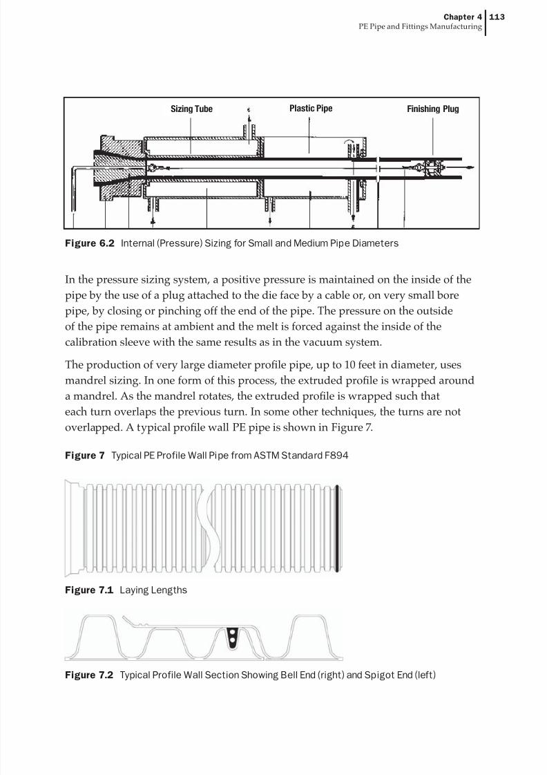
The production of very large diameter prole pipe, up to 10 feet in diameter, uses
mandrel sizing. In one form of this process, the extruded prole is wrapped around
a mandrel. As the mandrel rotates, the extruded prole is wrapped such that
each turn overlaps the previous turn. In some other techniques, the turns are not
overlapped. A typical prole wall PE pipe is shown in Figure 7.
Sizing Tube Plastic Pipe Finishing Plug
Figure 7 Typical PE Profile Wall Pipe from ASTM Standard F894
Figure 7.1 Laying Lengths
Figure 7.2 Typical Profile Wall Section Showing Bell End (right) and Spigot End (left)

7/29/2019 HDPEChapter 04
http://slidepdf.com/reader/full/hdpechapter-04 10/19
Chapter 4
PE Pipe and Fittings Manufacturing114
Cooling
For either the vacuum or pressure sizing technique, the pipe must be cool enough so
that it maintains its circularity before it exits the cooling tank. Various methods of cooling are utilized to remove the residual heat out of the PE pipe. Depending upon
the pipe size, the system may use either total immersion or spray cooling. Spray
cooling is usually applied to large diameter pipe where total immersion would be
inconvenient. Smaller diameter pipe is usually immersed in a water bath. Cooling
water temperatures are typically in the optimum range of 40° to 50°F (4° to 10°C). The
total length of the cooling baths must be adequate to cool the pipe below 160°F (71°C)
in order to withstand subsequent handling operations.
Residual stresses generated by the cooling process within the pipe wall areminimized by providing annealing zones.(4) These zones are spaces between the
cooling baths which allow the heat contained within the inner pipe wall to radiate
outward and anneal the entire pipe wall. Proper cooling bath spacing is important
in controlling pipe wall stresses. Long-term pipe performance is improved when the
internal pipe wall stresses are minimized.
Pullers
The puller must provide the necessary force to pull the pipe through the entirecooling operation. It also maintains the proper wall thickness control by providing
a constant pulling rate. The rate at which the pipe is pulled, in combination with the
extruder screw speed, determines the wall thickness of the nished pipe. Increasing
the puller speed at a constant screw speed reduces the wall thickness, while
reducing the puller speed at the same screw speed increases the wall thickness.
Standards of ASTM International and other specications require that the pipe
be marked at frequent intervals. The markings include nominal pipe size, type of
plastic, SDR and/or pressure rating, and manufacturer’s name or trademark andmanufacturing code. The marking is usually ink, applied to the pipe surface by
an offset roller. Other marking techniques include hot stamp, ink jet and indent
printing. If indent printing is used, the mark should not reduce the wall thickness
to less than the minimum value for the pipe or tubing, and the long-term strength
of the pipe or tubing must not be affected. The mark should also not allow leakage
channels when gasket or compression ttings are used to join the pipe or tubing.
Take-off Equipment
Most pipe four inches or smaller can be coiled for handling and shipping
convenience. Some manufacturers have coiled pipe as large as 6 inch. Equipment
allows the pipe to be coiled in various lengths. Depending upon the pipe

7/29/2019 HDPEChapter 04
http://slidepdf.com/reader/full/hdpechapter-04 11/19
Chapter 4
PE Pipe and Fittings Manufacturing115
diameter, lengths of up to 10,000 feet are possible. This is advantageous when long
uninterrupted lengths of pipe are required - for example, when installing gas and
water pipes.
Saw Equipment and Bundling
Pipe four inches or more in diameter is usually cut into specied lengths for storage
and shipping. Typical lengths are 40 to 50 feet, which can be shipped easily by rail or
truck. The pipe is usually bundled before it is placed on the truck or railcar. Bundling
provides ease of handling and safety during loading and unloading.
Fittings Overview
The PE pipe industry has worked diligently to make PE piping systems as
comprehensive as possible. As such, various ttings are produced which increase the
overall use of the PE piping systems. Some typical ttings are shown in Figure 8.
PE ttings may be injection molded, fabricated or thermoformed. The following
section will briey describe the operations of each technique.
Injection Molded Fittings
Injection molded PE ttings are manufactured in sizes through 12-inch nominal
diameter. Typical molded ttings are tees, 45° and 90° elbows, reducers, couplings,
caps, ange adapters and stub ends, branch and service saddles, and self-tapping
saddle tees. Very large parts may exceed common injection molding equipment
capacities, so these are usually fabricated.
Equipment to mold ttings consists of a mold and an injection molding press, as
shown in Figure 9. The mold is a split metal block that is machined to form a part-
shaped cavity in the block. Hollows in the part are created by core pins shaped intothe part cavity. The molded part is created by lling the cavity in the mold block
through a lling port, called a gate. The material volume needed to ll the mold
cavity is called a shot.
The injection molding press has two parts; a press to open and close the mold block,
and an injection extruder to inject material into the mold block cavity. The injection
extruder is similar to a conventional extruder except that, in addition to rotating, the
extruder screw also moves lengthwise in the barrel. Injection molding is a cyclical
process. The mold block is closed and the extruder barrel is moved into contact withthe mold gate. The screw is rotated and then drawn back, lling the barrel ahead
of the screw with material. Screw rotation is stopped and the screw is rammed
forward, injecting molten material into the mold cavity under high pressure. The

7/29/2019 HDPEChapter 04
http://slidepdf.com/reader/full/hdpechapter-04 12/19
Chapter 4
PE Pipe and Fittings Manufacturing116
Figure 8.3 90° Socket Elbow
part in the mold block is cooled by water circulating through the mold block. When
the part has solidied, the extruder barrel and mold core pins are retracted, the mold
is opened, and the part is ejected.
Typical quality inspections are for knit line strength, voids, dimensions and pressure
tests. A knit line is formed when the molten PE material ows around a core pin and
joins together on the other side. While molding conditions are set to eliminate the
potential for voids, they can occur occasionally in heavier sections due to shrinkage
that takes place during cooling. Voids can be detected nondestructively by using
x-ray scans. If this is not available, samples can be cut into thin sections and
inspected visually.
Figure 8 Typical PE Pipe Fittings
Figure 8.1 Socket Tee Figure 8.2 Butt Tee
Figure 8.4 90° Butt Elbow
7/29/2019 HDPEChapter 04
http://slidepdf.com/reader/full/hdpechapter-04 13/19
Chapter 4
PE Pipe and Fittings Manufacturing117
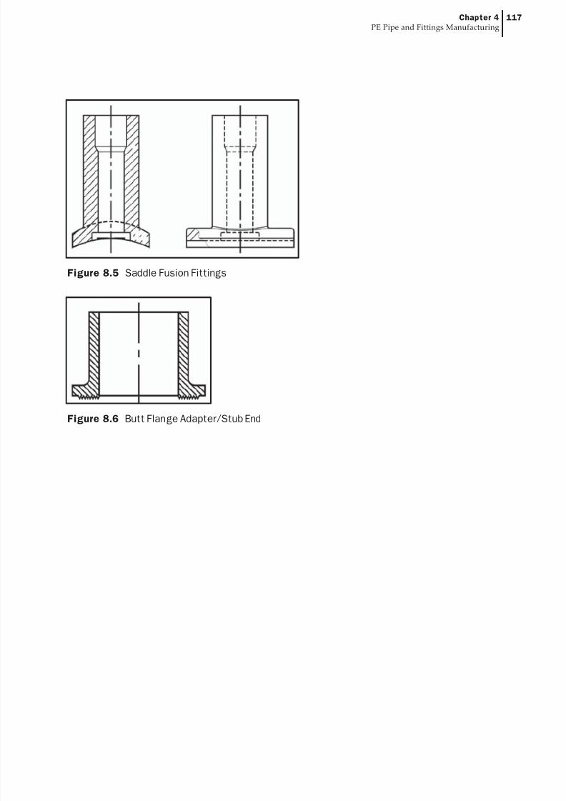
Figure 8.5 Saddle Fusion Fittings
Figure 8.6 Butt Flange Adapter/Stub End

7/29/2019 HDPEChapter 04
http://slidepdf.com/reader/full/hdpechapter-04 14/19
Chapter 4
PE Pipe and Fittings Manufacturing118
Figure 9 Construction and Mode of Operation of a Reciprocating Screw Injection Unit
(Courtesy of Hoechst Celanese Corporation)
Fabricated Fittings
Fully pressure-rated, full bore fabricated ttings are available from select ttings
fabricators. Fabricated ttings are constructed by joining sections of pipe,
machined blocks, or molded ttings together to produce the desired conguration.
Components can be joined by butt or socket heat fusion, electrofusion, hot gas
welding or extrusion welding techniques. It is not recommended to use either
hot gas or extrusion welding for pressure service ttings since the resultant jointstrength is signicantly less than that of the other heat fusion joining methods.
Fabricated ttings designed for full pressure service are joined by heat fusion and
must be designed with additional material in regions of sharp geometrical changes,
a. injection stage
b. freeze time with follow-up
pressurec. demouldingofnishedarticle
1. locking mechanism
2. moving mounting plate
3. mold cavity plate4. mold core plate
5. stationery mounting plate
6. plasticating cylinder
7. feed hopper
8. hydralic motor (screw drive)
9. hydralic cylinder of injection unit10. pressure gauge
11. follw-up pressure limit switch
12. screw stroke adjusment
c.
b.
a.
7/29/2019 HDPEChapter 04
http://slidepdf.com/reader/full/hdpechapter-04 15/19
Chapter 4
PE Pipe and Fittings Manufacturing119
regions that are subject to high localized stress. The common commercial practice
is to increase wall thickness in high-stress areas by fabricating ttings from heavier
wall pipe sections. The increased wall thickness may be added to the OD, whichprovides for a full-ow ID; or it may be added to the ID, which slightly restricts ID
ow. This is similar to molded ttings that are molded with a larger OD, heavier
body wall thickness. If heavy-wall pipe sections are not used, the conventional
practice is to reduce the pressure rating of the tting. The lowest-pressure-rated
component in a pipeline determines the operating pressure of the piping system.
Various manufacturers address this reduction process in different manners.
Reinforced over-wraps are sometimes used to increase the pressure rating of a
tting. Encasement in concrete, with steel reinforcement or rebar, is also used for thesame purpose. Contact the tting manufacturer for specic recommendations.
Very large diameter ttings require special handling during shipping, unloading,
and installation. Precautions should be taken to prevent bending moments that
could stress the tting during these periods. Consult the ttings manufacturer for
specics. These ttings are sometimes wrapped with a reinforcement material, such
as berglass, for protection.
Thermoformed Fittings
Thermoformed ttings are manufactured by heating a section of pipe and then
using a forming tool to reshape the heated area. Examples are sweep elbows, swaged
reducers, and forged stub ends. The area to be shaped is immersed in a hot liquid
bath and heated to make it pliable. It is removed from the heating bath and reshaped
in the forming tool. Then the new shape must be held until the part has cooled.
Electrofusion Couplings
Electrofusion couplings and ttings are manufactured by either molding in a
similar manner as that previously described for butt and socket fusion ttings ormanufactured from pipe stock. A wide variety of couplings and other associated
ttings are available from ½” CTS thru 28” IPS. Fittings are also available for ductile
iron sized PE pipe. These couplings are rated as high as FM 200.
Electrofusion ttings are manufactured with a coil-like integral heating element.
These ttings are installed utilizing a fusion processor, which provides the
proper energy to provide a fusion joint stronger than the joined pipe sections. All
electrofusion ttings are manufactured to meet the requirements of ASTM F-1055.
Injection Molded Couplings
Some mechanical couplings are manufactured by injection molding in a similar
manner as previously described for butt and socket fusion ttings. The external

7/29/2019 HDPEChapter 04
http://slidepdf.com/reader/full/hdpechapter-04 16/19
Chapter 4
PE Pipe and Fittings Manufacturing120
Figure 10 Typical Fabricated Fittings

7/29/2019 HDPEChapter 04
http://slidepdf.com/reader/full/hdpechapter-04 17/19
Chapter 4
PE Pipe and Fittings Manufacturing121
coupling body is typically injection molded and upon nal assembly will include
internal components such as steel stiffeners, o-rings, gripping collets, and other
components depending upon the design. A wide variety of coupling congurationsare available including tees, ells, caps, reducers, and repair couplings. Sizes for
joining PE pipe and tubing are typically from ½ ” CTS through 2” IPS. All injection
molded couplings are manufactured to meet the requirements of ASTM D2513.
Quality Control/Quality Assurance Testing
Quality is engineered into the pipe and tting product during the entire
manufacturing process. The three phases of quality control for the pipe
manufacturer involve the incoming raw material, the pipe or tting productionand the nished product. The combination of all three areas ensures that the nal
product will fulll the requirements of the specication to which it was made.
Testing the incoming resin is the rst step in the quality control program. It is
usually checked for contamination, melt ow rate and density. Any resin that
does not meet the raw material specication is not used for the production of
specication-grade pipe or tting.
During the manufacturing step, the pipe or tting producer routinely performs
quality control tests on samples. This veries that proper production procedures andcontrols were implemented during production.
Once the product has been produced, it undergoes a series of quality assurance tests
to ensure that it meets the minimum specications as required by the appropriate
standard. (See Handbook Chapter on Test Methods and Codes.)
The manufacturing specications for piping products list the tests that are required.
There are several quality control tests that are common in most ASTM PE standards.
For gas service piping systems, refer to PPI Technical Report TR-32 (7) for a typical
quality control program for gas system piping, or to the AGA Plastic Pipe Manual
for Gas Service (1). The typical QC/QA tests found in most standards are described
below.
Workmanship, Finish, and Appearance
According to ASTM product specications, the pipe, tubing, and ttings shall
be homogeneous throughout and free of visible cracks, holes, foreign inclusions,
blisters, and dents or other injurious defects. The pipe tubing and ttings shall be
as uniform as commercially practicable in color, opacity, density and other physicalproperties.

7/29/2019 HDPEChapter 04
http://slidepdf.com/reader/full/hdpechapter-04 18/19
Chapter 4
PE Pipe and Fittings Manufacturing122
Dimensions
Pipe diameter, wall thickness, ovality, and length are measured on a regular basis
to insure compliance with the prevailing specication. All ttings have to complywith the appropriate specication for proper dimensions and tolerances. All
measurements are made in accordance with ASTM D2122, Standard Test Method of
Determining Dimensions of Thermoplastic Pipe and Fittings (2).
Physical Property Tests
Several tests are conducted to ensure that the nal pipe product complies to the
applicable specication. Depending upon the specication, the type and the
frequency of testing will vary. More details about industry standard requirementscan be found in the chapter on specications, test methods and codes in this
Handbook.
The following tests, with reference to the applicable ASTM standard (2) , are generally
required in many product specications such as natural gas service. The following
list of tests was taken from the American Gas Association Manual for Plastic Gas
Pipe (1) to serve as an example of typical tests for gas piping systems.
ASTM TESTS
Sustained Pressure D1598
Burst Pressure D1599
Apparent Tensile Strength D2290
Neither the sustained pressure test or the elevated temperature pressure test
are routine quality assurance tests. Rather, they are less frequently applied tests
required by the applicable standards to conrm and assure that the established
process system and materials being used produce quality product meeting therequirements of the standard.
There are other tests that are used that are not ASTM test methods. They are
accepted by the industry since they further ensure product reliability. One such test,
required by applicable AWWA Standards, is the Bend-Back Test (1) which is used to
indicate inside surface brittleness under highly strained test conditions. In this test,
a ring of the pipe is cut and then subjected to a reverse 180-degree bend. Any signs
of surface embrittlement, such as cracking or crazing, constitute a failure. The
presence of this condition is cause for rejection of the pipe.

7/29/2019 HDPEChapter 04
http://slidepdf.com/reader/full/hdpechapter-04 19/19
Chapter 4
PE Pipe and Fittings Manufacturing123
Quality Assurance Summary
Through the constant updating of industry standards, the quality performance of
the PE pipe and tting industry is continually evolving. Each year, PPI and ASTMwork to improve standards on plastic pipe which include the latest test methods and
recommended practices. Resin producers, pipe extruders, and ttings manufacturers
incorporate these revisions into their own QA/QC practices to insure compliance
with these standards. In this way, the exceptional performance and safety record of
the PE pipe industry is sustained.
Summary
This chapter provides an overview of the production methods and quality assuranceprocedures used in the manufacture of PE pipe and ttings. The purpose of this
chapter is to create a familiarity with the processes by which these engineered
piping products are made. Through a general understanding of these fundamental
processes, the reader should be able to develop an appreciation for the utility and
integrity of PE piping systems.
References1. AGA Plastic Pipe Manual for Gas Service . (2001). Catalog No. XR0185, American Gas Association, Arlington , VA.
2. Annual Book of ASTM Standards . (2005). Volume 08.04, Plastic Pipe an d Building Products, American Society forTesting and Materials, Philadelphia, PA.
3. Kamp, W., & H. D. Kurz. (1980). Cooling Sections in Polyolefin Pipe Extrusion , Kunststoffe 70 , pp. 257-263, EnglishTranslation.
4. Policies and Procedures for Developing Hydrostatic Design Basis (HDB), Pressure Design Basis (PDB), StrengthDesign Basis (SDB), and Minimum Required Strength (MRS) Rating for Thermoplastic Piping Materials or Pipe(2005). Report TR-3, Plastics Pipe Institute, Irving, TX.
5. PPI Listing of Hydrostatic Design Basis (HDB), Strength Design Basis (SDB), Pressure Design Basis (PDB) andMinimum Required Strength (MRS) Ratings for Thermoplastic Piping Materials or Pipe (2005). Report TR-4,Plastics Pipe Institute, Irving, TX.
6. Recommen ded Minimum In- Plant Quality Control Program for Production of PE Gas Distribution Piping Systems.(1989). Report TR-32, Plastics Pipe Institute, Irving, TX.
7. Schiedrum, H. 0. (1974). The Design of Pipe Dies, Plastverarbeiter , No. 10, English Translation.8. Rauwendaal, C. (1986). Polymer Extrusion , MacMillan Publishing Company, Inc., New York, NY.
9. Screw and Barrel Technology . (1985). Spirex Corporation, Youngstown, OH .10. Peacock, Andrew J. (2000). Handbook of PE , Marcel Decker, Inc. New York, NY.