Embed Size (px)
Citation preview
User Manual HDO773 59300569 Rev.001 25.1.2016 1(24)
HDO Series
User Manual
Teleste Corporation
HDO773
C-band DWDM fibre transmitter
User Manual HDO773 59300569 Rev.001 25.1.2016 2(24)
Contents Introduction ........................................................................................................ 3 Parts and functions ........................................................................................... 4
Front and rear panels .......................................................................................... 4 Installation ............................................................................................................ 6 Indicators ............................................................................................................. 8 Software .............................................................................................................. 9
Alarms ................................................................................................................ 10 Viewer pages .................................................................................................... 11
Status ................................................................................................................. 11 Adjustments ....................................................................................................... 12 Pilots .................................................................................................................. 14 Monitoring .......................................................................................................... 17 Spectrum ........................................................................................................... 20 Properties .......................................................................................................... 23 Legal declarations ........................................................................................... 24
User Manual HDO773 59300569 Rev.001 25.1.2016 3(24)
Introduction
HDO773 is a high performance directly modulated C band DWDM transmitter for forward path fibre optic links in CATV and FTTx networks. It is compatible with HDO optical headend platform and installed in HDX installation frame.
HDO773 is able to carry all kind of analog or/ and digital channel loading on the whole frequency band. HDO773 transmitter contains an electrical dispersion compensator that is important especially when analog channels are transmitted to longer distances. HDO773 is available on different optical wavelengths in accordance with the ITU wavelength grid.
HDO773 has two equal input sections with level and slope adjustments to support broadcast and narrowcast signal distribution. The RF isolation between the input branches is high minimising the leakage of narrowcast signals into unwanted narrowcast node segments. The power consumption is low but HDO773 still offers the high performance and the widest variety of features.
Caution! This unit employs a laser. Due to the invisible laser radiation all necessary safety instructions must be followed during the installation and maintenance operations. In a properly closed system the normal operation of these components does not cause any radiation danger. The safety requirements for class 1M lasers are detailed in EN60825.
User Manual HDO773 59300569 Rev.001 25.1.2016 4(24)
Parts and functions
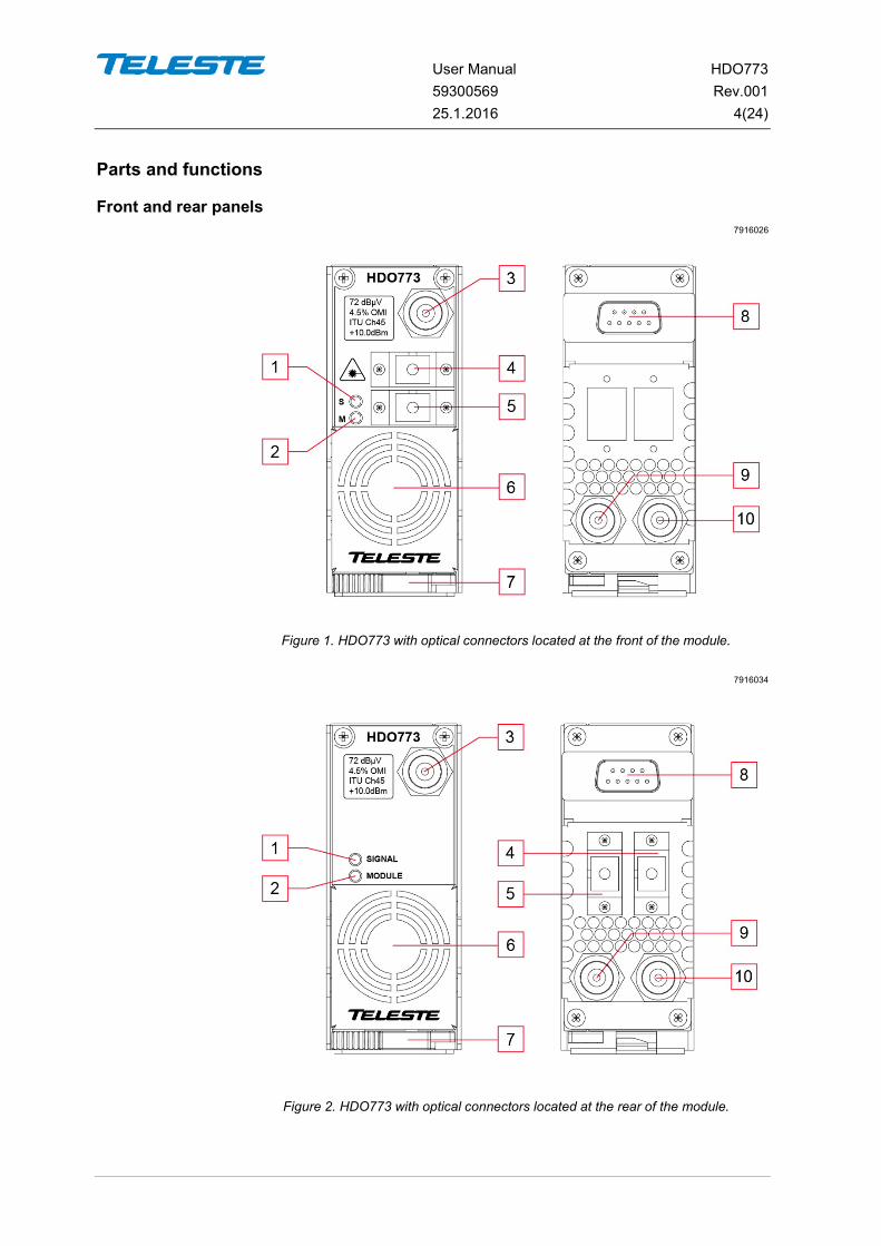
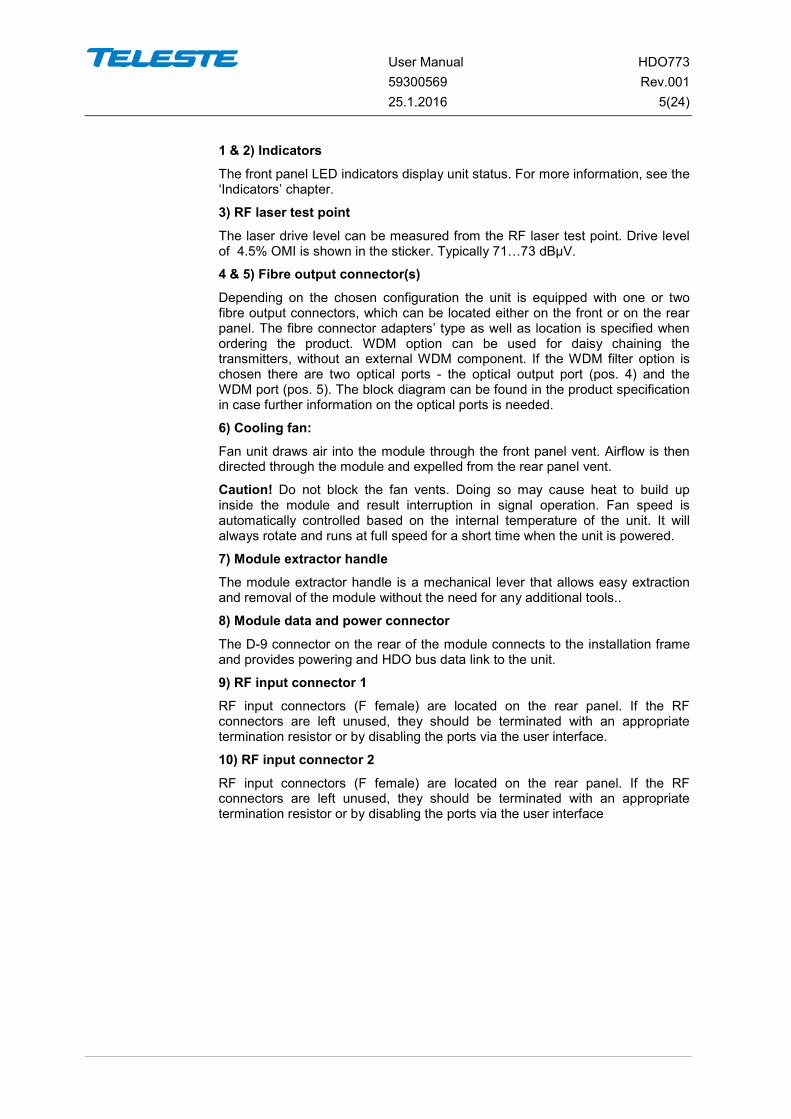
Front and rear panels 7916026
Figure 1. HDO773 with optical connectors located at the front of the module.
7916034
Figure 2. HDO773 with optical connectors located at the rear of the module.
User Manual HDO773 59300569 Rev.001 25.1.2016 5(24)
1 & 2) Indicators
The front panel LED indicators display unit status. For more information, see the ‘Indicators’ chapter.
3) RF laser test point
The laser drive level can be measured from the RF laser test point. Drive level of 4.5% OMI is shown in the sticker. Typically 71…73 dBµV.
4 & 5) Fibre output connector(s)
Depending on the chosen configuration the unit is equipped with one or two fibre output connectors, which can be located either on the front or on the rear panel. The fibre connector adapters’ type as well as location is specified when ordering the product. WDM option can be used for daisy chaining the transmitters, without an external WDM component. If the WDM filter option is chosen there are two optical ports - the optical output port (pos. 4) and the WDM port (pos. 5). The block diagram can be found in the product specification in case further information on the optical ports is needed.
6) Cooling fan:
Fan unit draws air into the module through the front panel vent. Airflow is then directed through the module and expelled from the rear panel vent.
Caution! Do not block the fan vents. Doing so may cause heat to build up inside the module and result interruption in signal operation. Fan speed is automatically controlled based on the internal temperature of the unit. It will always rotate and runs at full speed for a short time when the unit is powered.
7) Module extractor handle
The module extractor handle is a mechanical lever that allows easy extraction and removal of the module without the need for any additional tools..
8) Module data and power connector
The D-9 connector on the rear of the module connects to the installation frame and provides powering and HDO bus data link to the unit.
9) RF input connector 1
RF input connectors (F female) are located on the rear panel. If the RF connectors are left unused, they should be terminated with an appropriate termination resistor or by disabling the ports via the user interface.
10) RF input connector 2
RF input connectors (F female) are located on the rear panel. If the RF connectors are left unused, they should be terminated with an appropriate termination resistor or by disabling the ports via the user interface
User Manual HDO773 59300569 Rev.001 25.1.2016 6(24)
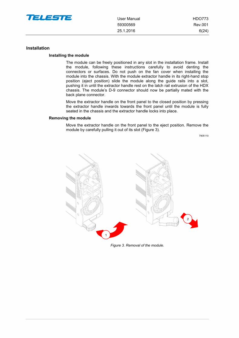
Installation Installing the module
The module can be freely positioned in any slot in the installation frame. Install the module, following these instructions carefully to avoid denting the connectors or surfaces. Do not push on the fan cover when installing the module into the chassis. With the module extractor handle in its right-hand stop position (eject position) slide the module along the guide rails into a slot, pushing it in until the extractor handle rest on the latch rail extrusion of the HDX chassis. The module’s D-9 connector should now be partially mated with the back plane connector.
Move the extractor handle on the front panel to the closed position by pressing the extractor handle inwards towards the front panel until the module is fully seated in the chassis and the extractor handle locks into place.
Removing the module
Move the extractor handle on the front panel to the eject position. Remove the module by carefully pulling it out of its slot (Figure 3).
7905110
Figure 3. Removal of the module.
1
2
User Manual HDO773 59300569 Rev.001 25.1.2016 7(24)
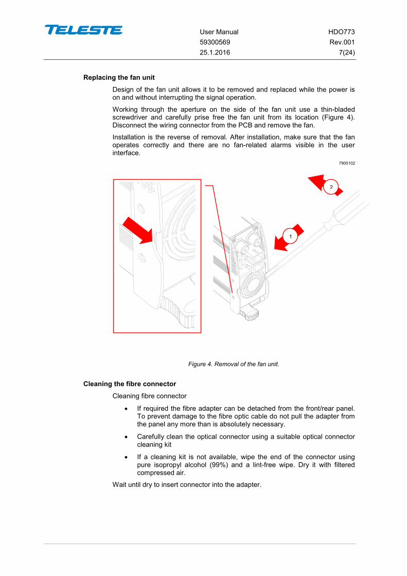
Replacing the fan unit
Design of the fan unit allows it to be removed and replaced while the power is on and without interrupting the signal operation.
Working through the aperture on the side of the fan unit use a thin-bladed screwdriver and carefully prise free the fan unit from its location (Figure 4). Disconnect the wiring connector from the PCB and remove the fan.
Installation is the reverse of removal. After installation, make sure that the fan operates correctly and there are no fan-related alarms visible in the user interface.
7905102
Figure 4. Removal of the fan unit.
Cleaning the fibre connector
Cleaning fibre connector
• If required the fibre adapter can be detached from the front/rear panel. To prevent damage to the fibre optic cable do not pull the adapter from the panel any more than is absolutely necessary.
• Carefully clean the optical connector using a suitable optical connector cleaning kit
• If a cleaning kit is not available, wipe the end of the connector using pure isopropyl alcohol (99%) and a lint-free wipe. Dry it with filtered compressed air.
Wait until dry to insert connector into the adapter.
1
2
User Manual HDO773 59300569 Rev.001 25.1.2016 8(24)
Indicators The unit has two LEDs on the front panel labelled as Signal (S) and Module (M). These LEDs’ colours reflect the unit’s alarm status, i.e. what alarms are active. RF related alarms are indicated with Signal LED, others with Module LED.
If there are one or more “Major” alarms, the affected LED will be red. If there are no “Major” alarms, but one or more “Minor” alarms, the affected LED will be yellow. If there are no “Major” or “Minor” alarms, the LED will be green. Note that the “Notification” alarms do not affect LEDs.
During the power-up sequence both LEDs are yellow and fan runs at full speed.
Module LED blinks when configuration session (viewer) is open to the module.
Both LEDs blink simultaneously in red if application software cannot start.
See the ‘Alarms’ chapter for details on alarms and LED usage.
User Manual HDO773 59300569 Rev.001 25.1.2016 9(24)
Software
Establishing connection
All the needed configurations and adjustments can be carried out locally or remotely by using the CATVisor Commander software. A connection to HDO773 is possible using the following two methods:
- Remote IP connection through HDC100’s Ethernet port.
- Local connection using HDX021 connection cable between a USB port of a PC and the management bus connector of the HDX installation frame. Note! If there is a HDC100 (or other HDO bus master) connected to the bus, it cannot communicate with the HDO devices while Commander is connected to the bus. This also means that the EMS system cannot access HDO devices either. Therefore IP connection is recommended in systems equipped with HDC100.
More detailed hardware requirements and software installation instructions can be found from the Commander User Manual supplied with the software.
User Manual HDO773 59300569 Rev.001 25.1.2016 10(24)
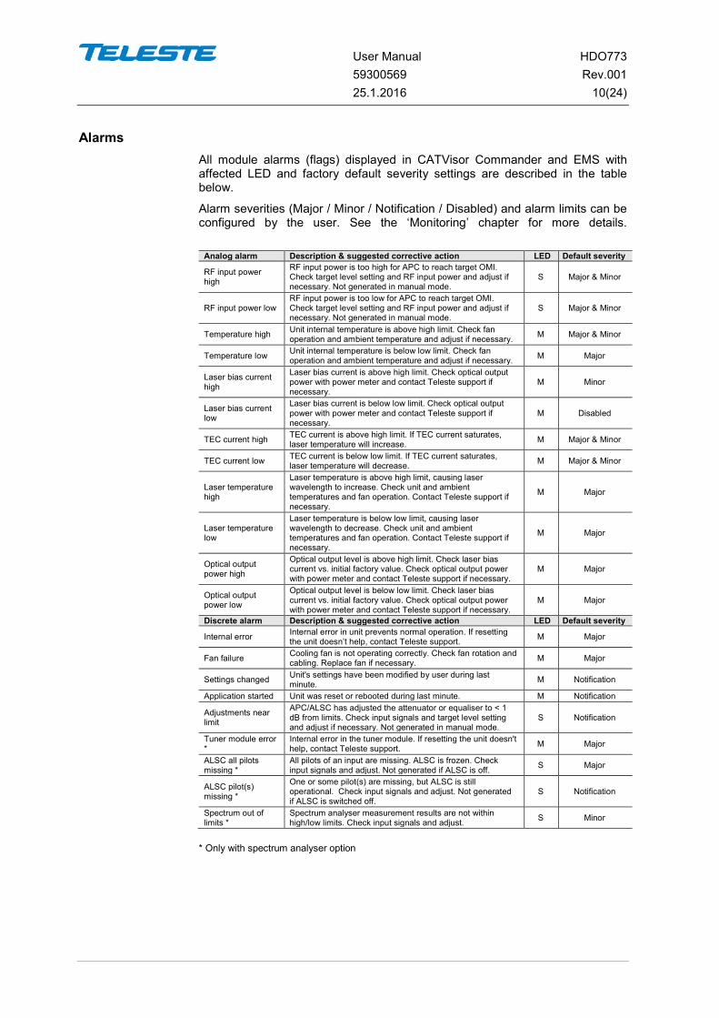
Alarms All module alarms (flags) displayed in CATVisor Commander and EMS with affected LED and factory default severity settings are described in the table below.
Alarm severities (Major / Minor / Notification / Disabled) and alarm limits can be configured by the user. See the ‘Monitoring’ chapter for more details.
Analog alarm Description & suggested corrective action LED Default severity
RF input power high
RF input power is too high for APC to reach target OMI. Check target level setting and RF input power and adjust if necessary. Not generated in manual mode.
S Major & Minor
RF input power low RF input power is too low for APC to reach target OMI. Check target level setting and RF input power and adjust if necessary. Not generated in manual mode.
S Major & Minor
Temperature high Unit internal temperature is above high limit. Check fan operation and ambient temperature and adjust if necessary. M Major & Minor
Temperature low Unit internal temperature is below low limit. Check fan operation and ambient temperature and adjust if necessary. M Major
Laser bias current high
Laser bias current is above high limit. Check optical output power with power meter and contact Teleste support if necessary.
M Minor
Laser bias current low
Laser bias current is below low limit. Check optical output power with power meter and contact Teleste support if necessary.
M Disabled
TEC current high TEC current is above high limit. If TEC current saturates, laser temperature will increase. M Major & Minor
TEC current low TEC current is below low limit. If TEC current saturates, laser temperature will decrease. M Major & Minor
Laser temperature high
Laser temperature is above high limit, causing laser wavelength to increase. Check unit and ambient temperatures and fan operation. Contact Teleste support if necessary.
M Major
Laser temperature low
Laser temperature is below low limit, causing laser wavelength to decrease. Check unit and ambient temperatures and fan operation. Contact Teleste support if necessary.
M Major
Optical output power high
Optical output level is above high limit. Check laser bias current vs. initial factory value. Check optical output power with power meter and contact Teleste support if necessary.
M Major
Optical output power low
Optical output level is below low limit. Check laser bias current vs. initial factory value. Check optical output power with power meter and contact Teleste support if necessary.
M Major
Discrete alarm Description & suggested corrective action LED Default severity
Internal error Internal error in unit prevents normal operation. If resetting the unit doesn’t help, contact Teleste support. M Major
Fan failure Cooling fan is not operating correctly. Check fan rotation and cabling. Replace fan if necessary. M Major
Settings changed Unit's settings have been modified by user during last minute. M Notification
Application started Unit was reset or rebooted during last minute. M Notification
Adjustments near limit
APC/ALSC has adjusted the attenuator or equaliser to < 1 dB from limits. Check input signals and target level setting and adjust if necessary. Not generated in manual mode.
S Notification
Tuner module error *
Internal error in the tuner module. If resetting the unit doesn't help, contact Teleste support. M Major
ALSC all pilots missing *
All pilots of an input are missing. ALSC is frozen. Check input signals and adjust. Not generated if ALSC is off. S Major
ALSC pilot(s) missing *
One or some pilot(s) are missing, but ALSC is still operational. Check input signals and adjust. Not generated if ALSC is switched off.
S Notification
Spectrum out of limits *
Spectrum analyser measurement results are not within high/low limits. Check input signals and adjust. S Minor
* Only with spectrum analyser option
User Manual HDO773 59300569 Rev.001 25.1.2016 11(24)
Viewer pages
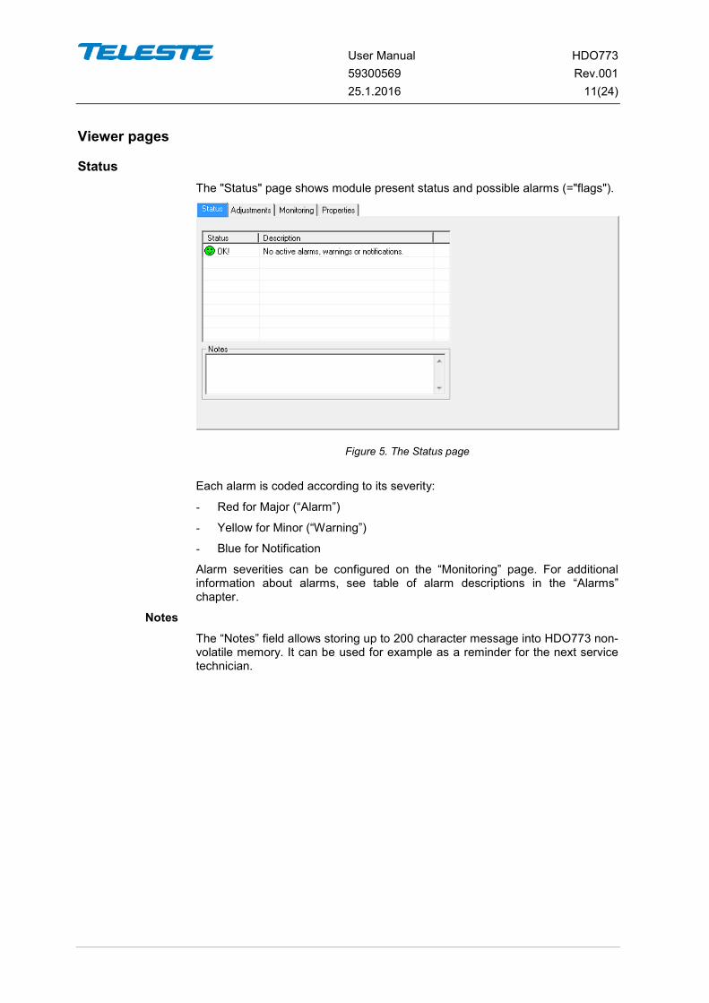
Status The "Status" page shows module present status and possible alarms (="flags").
Figure 5. The Status page
Each alarm is coded according to its severity:
- Red for Major (“Alarm”)
- Yellow for Minor (“Warning”)
- Blue for Notification
Alarm severities can be configured on the “Monitoring” page. For additional information about alarms, see table of alarm descriptions in the “Alarms” chapter.
Notes
The “Notes” field allows storing up to 200 character message into HDO773 non-volatile memory. It can be used for example as a reminder for the next service technician.
User Manual HDO773 59300569 Rev.001 25.1.2016 12(24)
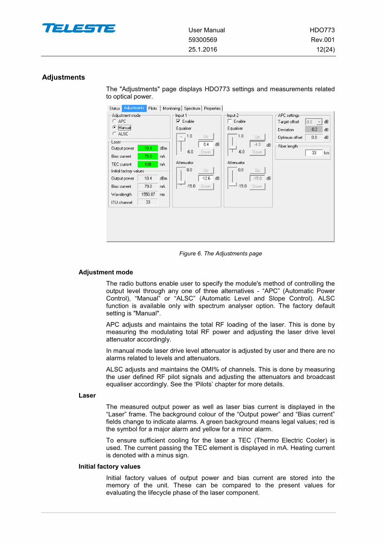
Adjustments The "Adjustments" page displays HDO773 settings and measurements related to optical power.
Figure 6. The Adjustments page
Adjustment mode
The radio buttons enable user to specify the module's method of controlling the output level through any one of three alternatives - “APC” (Automatic Power Control), “Manual” or “ALSC” (Automatic Level and Slope Control). ALSC function is available only with spectrum analyser option. The factory default setting is "Manual".
APC adjusts and maintains the total RF loading of the laser. This is done by measuring the modulating total RF power and adjusting the laser drive level attenuator accordingly.
In manual mode laser drive level attenuator is adjusted by user and there are no alarms related to levels and attenuators.
ALSC adjusts and maintains the OMI% of channels. This is done by measuring the user defined RF pilot signals and adjusting the attenuators and broadcast equaliser accordingly. See the ‘Pilots’ chapter for more details.
Laser
The measured output power as well as laser bias current is displayed in the “Laser” frame. The background colour of the “Output power” and “Bias current” fields change to indicate alarms. A green background means legal values; red is the symbol for a major alarm and yellow for a minor alarm.
To ensure sufficient cooling for the laser a TEC (Thermo Electric Cooler) is used. The current passing the TEC element is displayed in mA. Heating current is denoted with a minus sign.
Initial factory values
Initial factory values of output power and bias current are stored into the memory of the unit. These can be compared to the present values for evaluating the lifecycle phase of the laser component.
User Manual HDO773 59300569 Rev.001 25.1.2016 13(24)
Input 1 / Input 2
Inputs in HDO773 can be independently disabled via the checkboxes on the top of the frame. When an input is disabled an equivalent attenuator is set into the maximum value. If input 2 is disabled the unit completely shuts down the corresponding RF stage to minimise power consumption. If HDO773 is used as one input transmitter it is recommended to disable the input 2 for power saving reasons. The setting ‘Input 2 disabled’ is also the factory setting.
The “Equaliser” slider is used to equalise the frequency response of signals. Adjustment is done in 0.2 dB steps over a range of -6.0…+1 dB. The equaliser circuit can also be adjusted by typing a value into the field or using the step up/down buttons. Note that the adjustment value displays the setting of the equaliser circuit and does not directly indicate the actual slope of the transmitter.
The “Attenuator” is used to control the attenuation level of the input signals. The attenuation level of the input can be adjusted in 0.2 dB steps over a range of 0.0…-15.0 dB. This level is adjusted with the “Attenuator” slider. Attenuation can also be adjusted by typing a value into the field or using the step up/down buttons.
When APC adjustment mode is enabled it changes “Attenuator” control field to read only and adjusts the total RF loading of the laser. Input 1 and input 2 attenuators are linked together and the difference between the attenuator values (1 and 2) is maintained during the operation in APC mode. In the case the total RF input power changes so much that one of the attenuators drifts to the low or high limit the other attenuator continues the adjustment. The difference between the attenuator values is returned when the total power recovers.
APC settings
APC circuitry tries to maintain certain RF loading for the laser by adjusting the drive level towards the level specified in “Target offset” field. The measured adjustment error is shown in the “Deviation” field. APC circuitry tries to keep this difference close to zero.
Target offset value of 0 dB corresponds to 4.5 % OMI with 42 modulated channels. Optimum offset displays the factory measured value with which the distortion specifications are met.
Fiber length
The chirp-dispersion induced distortion compensation requires information about the transmission distance. Distortion is compensated for the chosen distance, but may be relatively poor for other fibre distances. Accurate information in this field is essential for correct operation of the device. Depending on the channel load a good performance is available in the window of ±3…6 km around the set value.
User Manual HDO773 59300569 Rev.001 25.1.2016 14(24)
Pilots This page is visible only with spectrum analyser option.
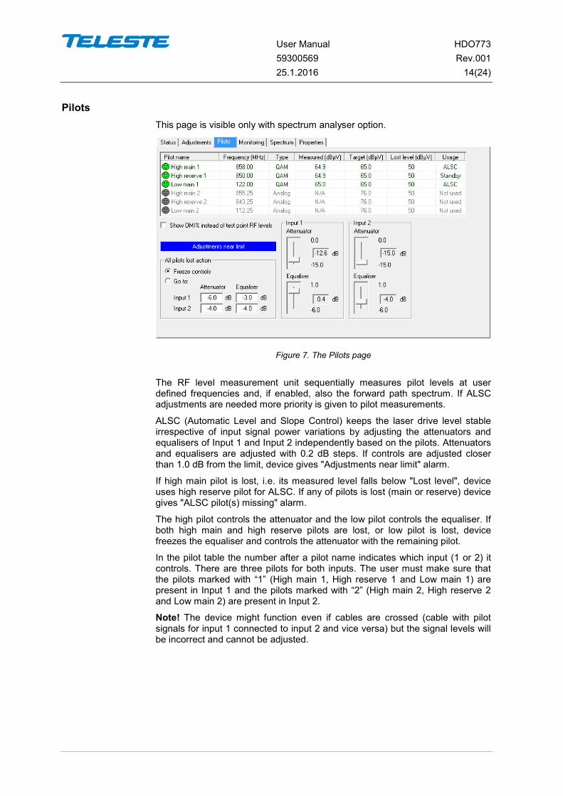
Figure 7. The Pilots page
The RF level measurement unit sequentially measures pilot levels at user defined frequencies and, if enabled, also the forward path spectrum. If ALSC adjustments are needed more priority is given to pilot measurements.
ALSC (Automatic Level and Slope Control) keeps the laser drive level stable irrespective of input signal power variations by adjusting the attenuators and equalisers of Input 1 and Input 2 independently based on the pilots. Attenuators and equalisers are adjusted with 0.2 dB steps. If controls are adjusted closer than 1.0 dB from the limit, device gives "Adjustments near limit" alarm.
If high main pilot is lost, i.e. its measured level falls below "Lost level", device uses high reserve pilot for ALSC. If any of pilots is lost (main or reserve) device gives "ALSC pilot(s) missing" alarm.
The high pilot controls the attenuator and the low pilot controls the equaliser. If both high main and high reserve pilots are lost, or low pilot is lost, device freezes the equaliser and controls the attenuator with the remaining pilot.
In the pilot table the number after a pilot name indicates which input (1 or 2) it controls. There are three pilots for both inputs. The user must make sure that the pilots marked with “1” (High main 1, High reserve 1 and Low main 1) are present in Input 1 and the pilots marked with “2” (High main 2, High reserve 2 and Low main 2) are present in Input 2.
Note! The device might function even if cables are crossed (cable with pilot signals for input 1 connected to input 2 and vice versa) but the signal levels will be incorrect and cannot be adjusted.
User Manual HDO773 59300569 Rev.001 25.1.2016 15(24)
Pilot table
Each pilot signal is displayed in the table with the following information:
Pilot name: Icon and pilot name colour coding indicates pilot status: green for pilot OK, red for pilot lost, grey for pilot disabled.
Frequency (MHz): Pilot signal frequency, adjustable in 0.25 MHz steps.
Type: Detector type. The measurement detector can be individually selected for each frequency between peak detect (“Analog”) and averaging (“QAM”).
Measured (dBµV): Measured level of pilot signal.
Target (dBµV): Pilot signal target level for ALSC operation.
Lost level (dBµV): Limit below which the pilot is considered as lost. This should be well below "Target" for correct operation.
Usage: Usage status of the pilot signal. ALSC / Standby / Not used.
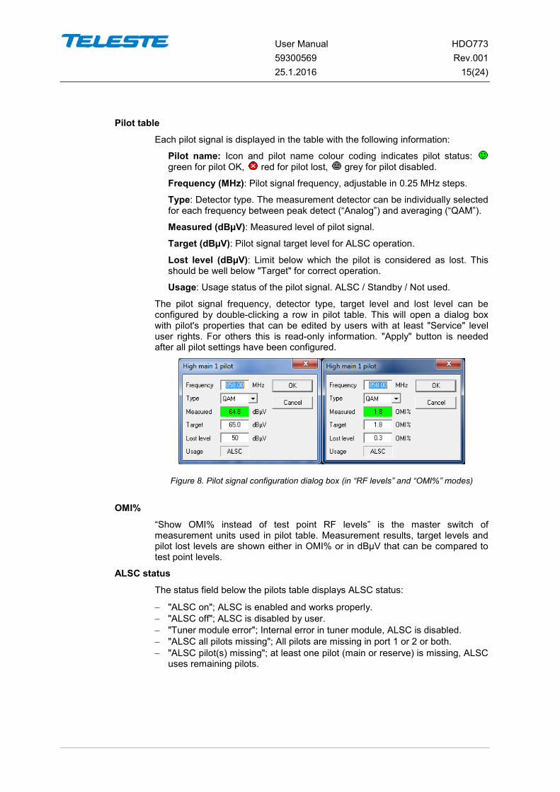
The pilot signal frequency, detector type, target level and lost level can be configured by double-clicking a row in pilot table. This will open a dialog box with pilot's properties that can be edited by users with at least "Service" level user rights. For others this is read-only information. "Apply" button is needed after all pilot settings have been configured.
Figure 8. Pilot signal configuration dialog box (in “RF levels” and “OMI%” modes)
OMI%
“Show OMI% instead of test point RF levels” is the master switch of measurement units used in pilot table. Measurement results, target levels and pilot lost levels are shown either in OMI% or in dBµV that can be compared to test point levels.
ALSC status
The status field below the pilots table displays ALSC status:
− "ALSC on"; ALSC is enabled and works properly. − "ALSC off"; ALSC is disabled by user. − "Tuner module error"; Internal error in tuner module, ALSC is disabled. − "ALSC all pilots missing"; All pilots are missing in port 1 or 2 or both. − "ALSC pilot(s) missing"; at least one pilot (main or reserve) is missing, ALSC
uses remaining pilots.
User Manual HDO773 59300569 Rev.001 25.1.2016 16(24)
All pilots lost action
When all pilots are lost in one of the ports, device gives "ALSC all pilots missing" alarm and that port operates as selected by "All pilots lost action" radio buttons:
− Freeze controls: Controls will keep the values they had immediately before the pilot signals were lost.
− Go to: Controls will slowly step to user defined values in the edit fields. If all pilots aren’t lost in the other port, ALSC continues to operate in that port.
Input 1 & 2
Values of Input 1 and Input 2 attenuator and equaliser controls are shown here. These controls are read-only. In “ALSC” mode the Input 1 and 2 attenuator and equaliser work independently.
User Manual HDO773 59300569 Rev.001 25.1.2016 17(24)
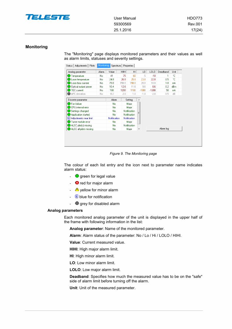
Monitoring The "Monitoring" page displays monitored parameters and their values as well as alarm limits, statuses and severity settings.
Figure 9. The Monitoring page
The colour of each list entry and the icon next to parameter name indicates alarm status:
- green for legal value
- red for major alarm
- yellow for minor alarm
- blue for notification
- grey for disabled alarm
Analog parameters
Each monitored analog parameter of the unit is displayed in the upper half of the frame with following information in the list:
Analog parameter: Name of the monitored parameter.
Alarm: Alarm status of the parameter: No / Lo / Hi / LOLO / HIHI.
Value: Current measured value.
HIHI: High major alarm limit.
HI: High minor alarm limit.
LO: Low minor alarm limit.
LOLO: Low major alarm limit.
Deadband: Specifies how much the measured value has to be on the "safe" side of alarm limit before turning off the alarm.
Unit: Unit of the measured parameter.
User Manual HDO773 59300569 Rev.001 25.1.2016 18(24)
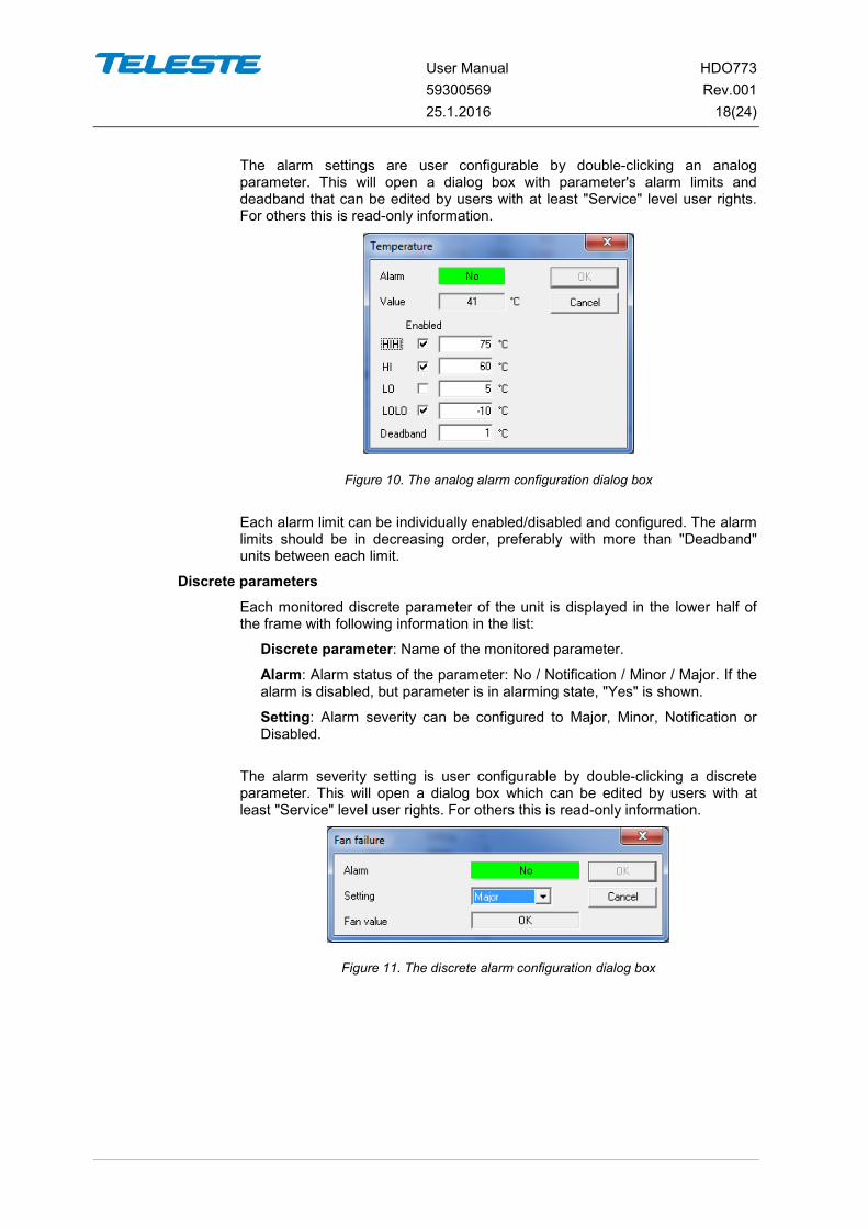
The alarm settings are user configurable by double-clicking an analog parameter. This will open a dialog box with parameter's alarm limits and deadband that can be edited by users with at least "Service" level user rights. For others this is read-only information.
Figure 10. The analog alarm configuration dialog box
Each alarm limit can be individually enabled/disabled and configured. The alarm limits should be in decreasing order, preferably with more than "Deadband" units between each limit.
Discrete parameters
Each monitored discrete parameter of the unit is displayed in the lower half of the frame with following information in the list:
Discrete parameter: Name of the monitored parameter.
Alarm: Alarm status of the parameter: No / Notification / Minor / Major. If the alarm is disabled, but parameter is in alarming state, "Yes" is shown.
Setting: Alarm severity can be configured to Major, Minor, Notification or Disabled.
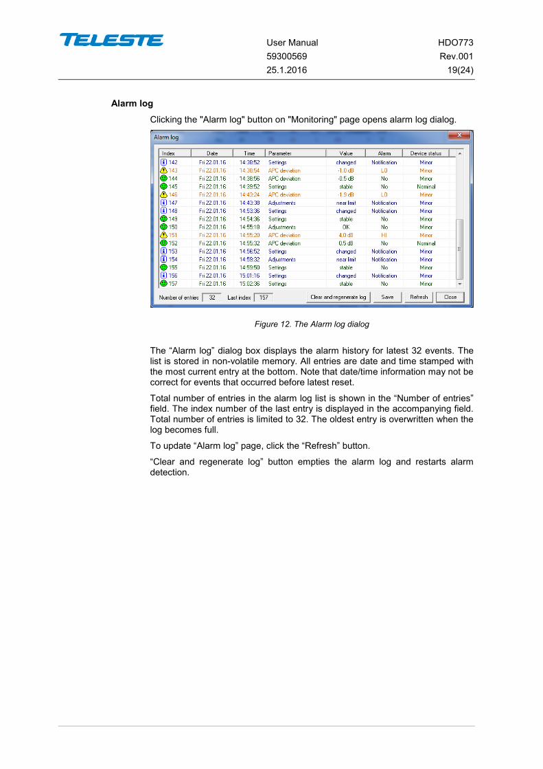
The alarm severity setting is user configurable by double-clicking a discrete parameter. This will open a dialog box which can be edited by users with at least "Service" level user rights. For others this is read-only information.
Figure 11. The discrete alarm configuration dialog box
User Manual HDO773 59300569 Rev.001 25.1.2016 19(24)
Alarm log
Clicking the "Alarm log" button on "Monitoring" page opens alarm log dialog.
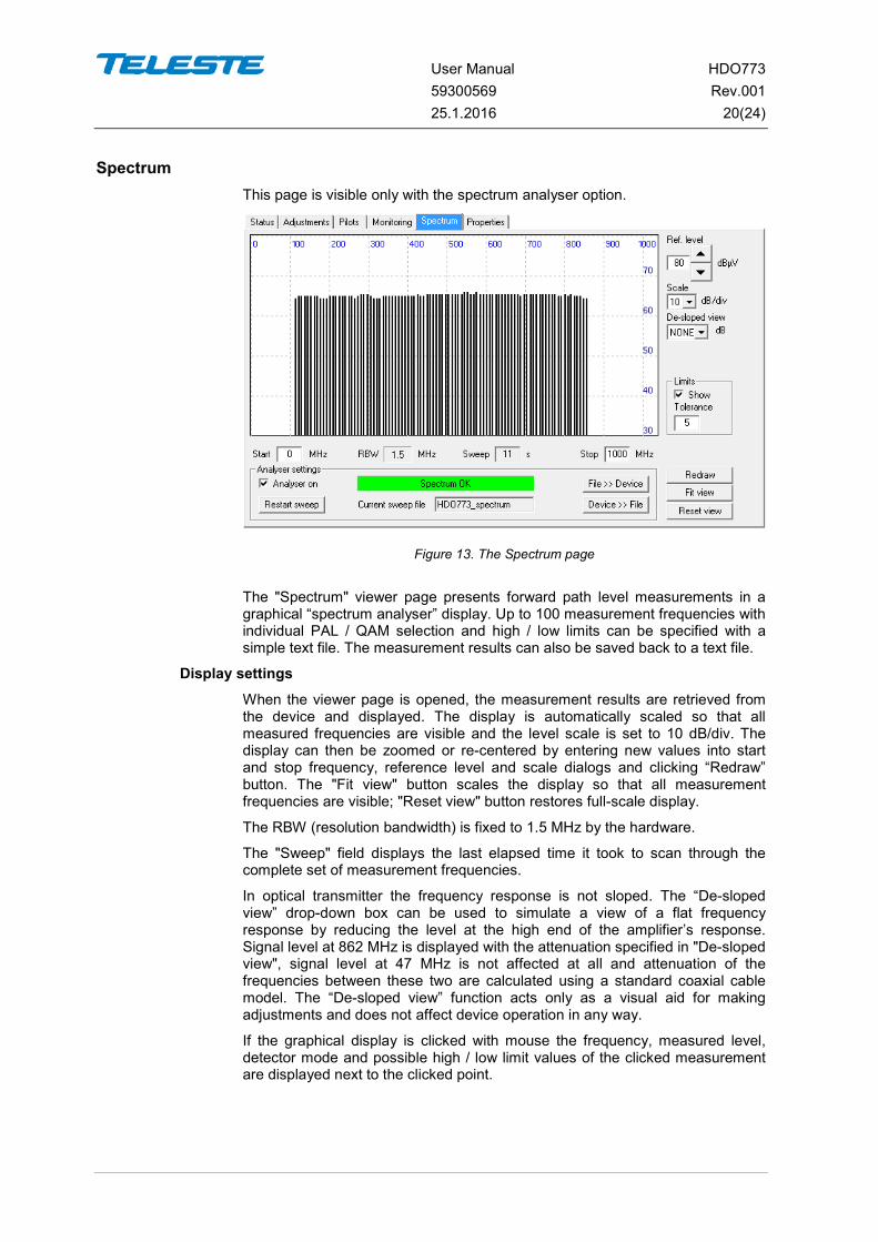
Figure 12. The Alarm log dialog
The “Alarm log” dialog box displays the alarm history for latest 32 events. The list is stored in non-volatile memory. All entries are date and time stamped with the most current entry at the bottom. Note that date/time information may not be correct for events that occurred before latest reset.
Total number of entries in the alarm log list is shown in the “Number of entries” field. The index number of the last entry is displayed in the accompanying field. Total number of entries is limited to 32. The oldest entry is overwritten when the log becomes full.
To update “Alarm log” page, click the “Refresh” button.
“Clear and regenerate log” button empties the alarm log and restarts alarm detection.
User Manual HDO773 59300569 Rev.001 25.1.2016 20(24)
Spectrum This page is visible only with the spectrum analyser option.
Figure 13. The Spectrum page
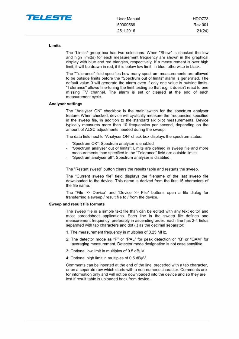
The "Spectrum" viewer page presents forward path level measurements in a graphical “spectrum analyser” display. Up to 100 measurement frequencies with individual PAL / QAM selection and high / low limits can be specified with a simple text file. The measurement results can also be saved back to a text file.
Display settings
When the viewer page is opened, the measurement results are retrieved from the device and displayed. The display is automatically scaled so that all measured frequencies are visible and the level scale is set to 10 dB/div. The display can then be zoomed or re-centered by entering new values into start and stop frequency, reference level and scale dialogs and clicking “Redraw” button. The "Fit view" button scales the display so that all measurement frequencies are visible; "Reset view" button restores full-scale display.
The RBW (resolution bandwidth) is fixed to 1.5 MHz by the hardware.
The "Sweep" field displays the last elapsed time it took to scan through the complete set of measurement frequencies.
In optical transmitter the frequency response is not sloped. The “De-sloped view” drop-down box can be used to simulate a view of a flat frequency response by reducing the level at the high end of the amplifier’s response. Signal level at 862 MHz is displayed with the attenuation specified in "De-sloped view", signal level at 47 MHz is not affected at all and attenuation of the frequencies between these two are calculated using a standard coaxial cable model. The “De-sloped view” function acts only as a visual aid for making adjustments and does not affect device operation in any way.
If the graphical display is clicked with mouse the frequency, measured level, detector mode and possible high / low limit values of the clicked measurement are displayed next to the clicked point.
User Manual HDO773 59300569 Rev.001 25.1.2016 21(24)
Limits
The “Limits” group box has two selections. When "Show" is checked the low and high limit(s) for each measurement frequency are shown in the graphical display with blue and red triangles, respectively. If a measurement is over high limit, it will be drawn in red; if it is below low limit, in blue, otherwise in black.
The "Tolerance" field specifies how many spectrum measurements are allowed to be outside limits before the "Spectrum out of limits" alarm is generated. The default value 0 will generate the alarm even if only one value is outside limits. "Tolerance" allows fine-tuning the limit testing so that e.g. it doesn't react to one missing TV channel. The alarm is set or cleared at the end of each measurement cycle.
Analyser settings
The “Analyser ON” checkbox is the main switch for the spectrum analyser feature. When checked, device will cyclically measure the frequencies specified in the sweep file, in addition to the standard six pilot measurements. Device typically measures more than 10 frequencies per second, depending on the amount of ALSC adjustments needed during the sweep.
The data field next to “Analyser ON” check box displays the spectrum status.
- “Spectrum OK”; Spectrum analyser is enabled - “Spectrum analyser out of limits”: Limits are defined in sweep file and more
measurements than specified in the “Tolerance” field are outside limits. - "Spectrum analyser off”: Spectrum analyser is disabled.
The “Restart sweep” button clears the results table and restarts the sweep.
The “Current sweep file” field displays the filename of the last sweep file downloaded to the device. This name is derived from the first 15 characters of the file name.
The “File >> Device” and “Device >> File” buttons open a file dialog for transferring a sweep / result file to / from the device.
Sweep and result file formats
The sweep file is a simple text file than can be edited with any text editor and most spreadsheet applications. Each line in the sweep file defines one measurement frequency, preferably in ascending order. Each line has 2-4 fields separated with tab characters and dot (.) as the decimal separator:
1. The measurement frequency in multiples of 0.25 MHz.
2: The detector mode as “P” or “PAL” for peak detection or “Q” or “QAM” for averaging measurement. Detector mode designation is not case sensitive.
3: Optional low limit in multiples of 0.5 dBµV.
4: Optional high limit in multiples of 0.5 dBµV.
Comments can be inserted at the end of the line, preceded with a tab character, or on a separate row which starts with a non-numeric character. Comments are for information only and will not be downloaded into the device and so they are lost if result table is uploaded back from device.
User Manual HDO773 59300569 Rev.001 25.1.2016 22(24)
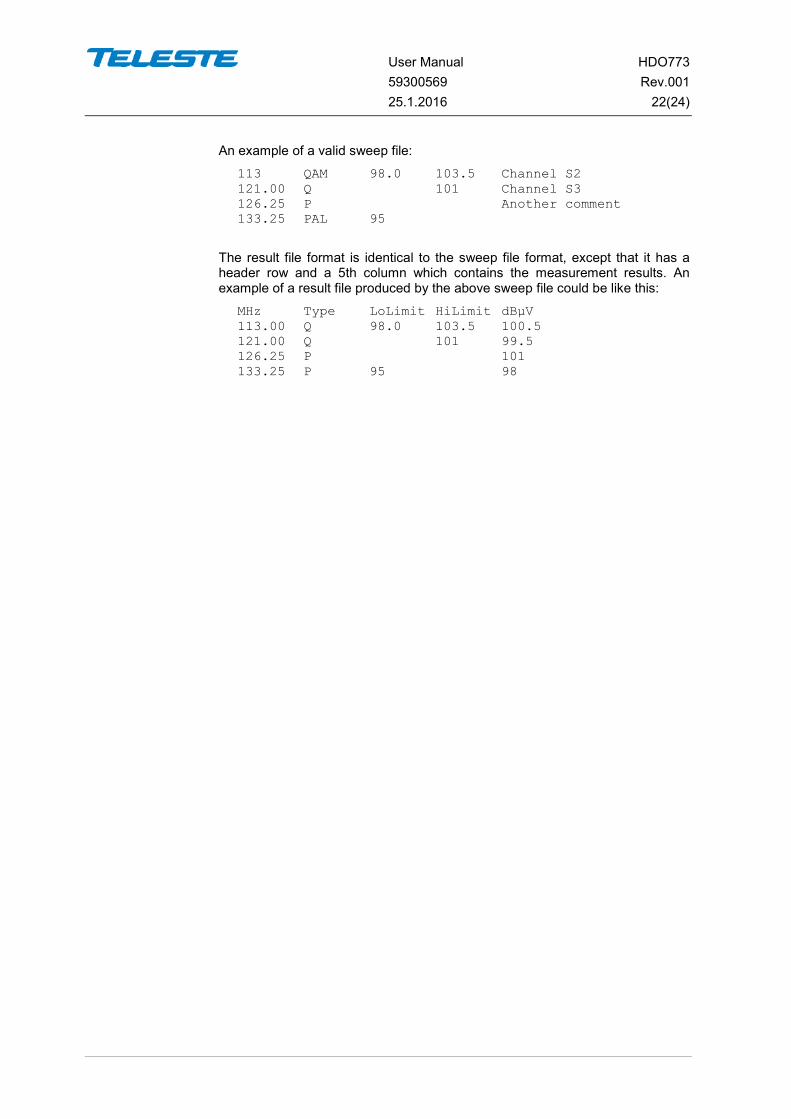
An example of a valid sweep file:
113 QAM 98.0 103.5 Channel S2 121.00 Q 101 Channel S3 126.25 P Another comment 133.25 PAL 95
The result file format is identical to the sweep file format, except that it has a header row and a 5th column which contains the measurement results. An example of a result file produced by the above sweep file could be like this:
MHz Type LoLimit HiLimit dBµV 113.00 Q 98.0 103.5 100.5 121.00 Q 101 99.5 126.25 P 101 133.25 P 95 98
User Manual HDO773 59300569 Rev.001 25.1.2016 23(24)
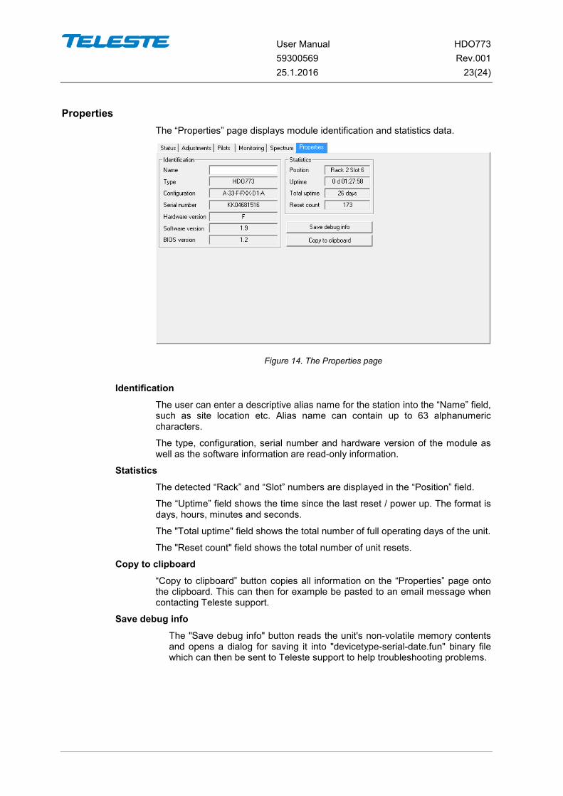
Properties The “Properties” page displays module identification and statistics data.
Figure 14. The Properties page
Identification
The user can enter a descriptive alias name for the station into the “Name” field, such as site location etc. Alias name can contain up to 63 alphanumeric characters.
The type, configuration, serial number and hardware version of the module as well as the software information are read-only information.
Statistics
The detected “Rack” and “Slot” numbers are displayed in the “Position” field.
The “Uptime” field shows the time since the last reset / power up. The format is days, hours, minutes and seconds.
The "Total uptime" field shows the total number of full operating days of the unit.
The "Reset count" field shows the total number of unit resets.
Copy to clipboard
“Copy to clipboard” button copies all information on the “Properties” page onto the clipboard. This can then for example be pasted to an email message when contacting Teleste support.
Save debug info
The "Save debug info" button reads the unit's non-volatile memory contents and opens a dialog for saving it into "devicetype-serial-date.fun" binary file which can then be sent to Teleste support to help troubleshooting problems.
User Manual HDO773 59300569 Rev.001 25.1.2016 24(24)
Legal declarations
Copyright © 2016 Teleste Corporation. All rights reserved.
TELESTE is a registered trademark of Teleste Corporation. Other product and service marks are property of their respective owners.
This document is protected by copyright laws. Unauthorized distribution or reproduction of this document is strictly prohibited.
Teleste reserves the right to make changes to any of the products described in this document without notice and all specifications are subject to change without notice. Current product specifications are stated in the latest versions of detailed product specifications.
To the maximum extent permitted by applicable law, under no circumstances shall Teleste be responsible for any loss of data or income or any special, incidental, consequential or indirect damages howsoever caused.
The contents of this document are provided "as is". Except as required by applicable law, no warranties of any kind, either express or implied, including, but not limited to, the implied warranties of merchantability and fitness for a particular purpose, are made in relation to the accuracy, reliability or contents of this document.
Teleste reserves the right to revise this document or withdraw it at any time without notice.
Teleste Corporation P.O. Box 323 FI-20101 Turku Street address: Telestenkatu 1, 20660 Littoinen FINLAND www.teleste.com