Embed Size (px)
Citation preview
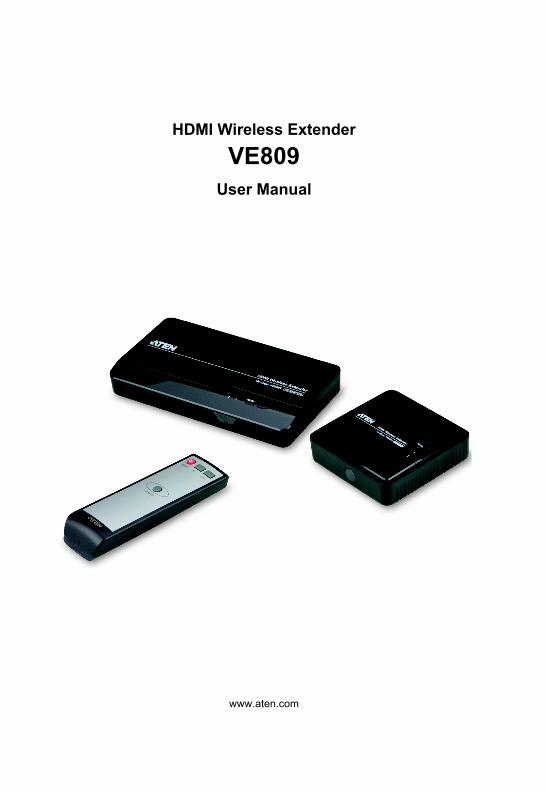
HDMI Wireless Extender
VE809User Manual
www.aten.com
VE809 User Manual
RoHS
This product is RoHS compliant.
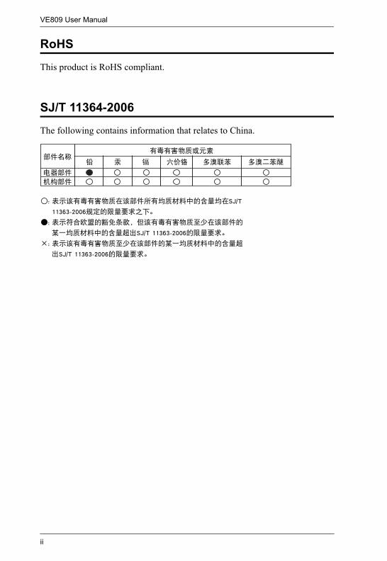
SJ/T 11364-2006
The following contains information that relates to China.
ii
VE809 User Manual
User Information
Online RegistrationBe sure to register your product at our online support center:
Telephone SupportFor telephone support, call this number:
User NoticeAll information, documentation, and specifications contained in this manual are subject to change without prior notification by the manufacturer. The manufacturer makes no representations or warranties, either expressed or implied, with respect to the contents hereof and specifically disclaims any warranties as to merchantability or fitness for any particular purpose. Any of the manufacturer's software described in this manual is sold or licensed as is. Should the programs prove defective following their purchase, the buyer (and not the manufacturer, its distributor, or its dealer), assumes the entire cost of all necessary servicing, repair and any incidental or consequential damages resulting from any defect in the software.
The manufacturer of this system is not responsible for any radio and/or TV interference caused by unauthorized modifications to this device. It is the responsibility of the user to correct such interference.
The manufacturer is not responsible for any damage incurred in the operation of this system if the correct operational voltage setting was not selected prior to operation. PLEASE VERIFY THAT THE VOLTAGE SETTING IS CORRECT BEFORE USE.
International http://eservice.aten.com
International 886-2-8692-6959
China 86-10-5255-0110
Japan 81-3-5615-5811
Korea 82-2-467-6789
North America 1-888-999-ATEN ext 4988
United Kingdom 44-8-4481-58923
iii
VE809 User Manual
Package Contents
The VE809 package consists of:1 VE809T HDMI Wireless Extender1 VE809R HDMI Wireless Extender1 IR Remote Control1 IR Blaster Cable1 Power Adapter (VE809T)1 Mini USB Power Adapter (VE809R)2 AAA Batteries1 HDMI Cable1 User Instructions*
Check to make sure that all the components are present and that nothing got damaged in shipping. If you encounter a problem, contact your dealer.
Read this manual thoroughly and follow the installation and operation procedures carefully to prevent any damage to the unit, and/or any of the devices connected to it.
* Features may have been added to the VE809 since this manual was published. Please visit our website to download the most up-to-date version.
© Copyright 2012 ATEN® International Co., Ltd.
Manual Date: 2012-12-10ATEN and the ATEN logo are registered trademarks of ATEN International Co., Ltd. All rights reserved.
All other brand names and trademarks are the registered property of their respective owners.
iv
VE809 User Manual
Contents
RoHS. . . . . . . . . . . . . . . . . . . . . . . . . . . . . . . . . . . . . . . . . . . . . . . . . . . . . . iiSJ/T 11364-2006. . . . . . . . . . . . . . . . . . . . . . . . . . . . . . . . . . . . . . . . . . . . . iiUser Information . . . . . . . . . . . . . . . . . . . . . . . . . . . . . . . . . . . . . . . . . . . . .iii
Online Registration . . . . . . . . . . . . . . . . . . . . . . . . . . . . . . . . . . . . . . . .iiiTelephone Support . . . . . . . . . . . . . . . . . . . . . . . . . . . . . . . . . . . . . . . .iiiUser Notice . . . . . . . . . . . . . . . . . . . . . . . . . . . . . . . . . . . . . . . . . . . . . .iii
Package Contents. . . . . . . . . . . . . . . . . . . . . . . . . . . . . . . . . . . . . . . . . . . ivAbout this Manual . . . . . . . . . . . . . . . . . . . . . . . . . . . . . . . . . . . . . . . . . . . viConventions . . . . . . . . . . . . . . . . . . . . . . . . . . . . . . . . . . . . . . . . . . . . . . . viiProduct Information. . . . . . . . . . . . . . . . . . . . . . . . . . . . . . . . . . . . . . . . . . vii
1. IntroductionOverview . . . . . . . . . . . . . . . . . . . . . . . . . . . . . . . . . . . . . . . . . . . . . . . . . . . 1Features . . . . . . . . . . . . . . . . . . . . . . . . . . . . . . . . . . . . . . . . . . . . . . . . . . . 2Requirements . . . . . . . . . . . . . . . . . . . . . . . . . . . . . . . . . . . . . . . . . . . . . . . 3
Source Device . . . . . . . . . . . . . . . . . . . . . . . . . . . . . . . . . . . . . . . . . . . . 3Display Device. . . . . . . . . . . . . . . . . . . . . . . . . . . . . . . . . . . . . . . . . . . . 3
Components . . . . . . . . . . . . . . . . . . . . . . . . . . . . . . . . . . . . . . . . . . . . . . . . 4VE809T Transmitter Front View . . . . . . . . . . . . . . . . . . . . . . . . . . . . . . 4VE809R Receiver Front View . . . . . . . . . . . . . . . . . . . . . . . . . . . . . . . . 4VE809T Transmitter Rear View. . . . . . . . . . . . . . . . . . . . . . . . . . . . . . . 5VE809R Receiver Rear View . . . . . . . . . . . . . . . . . . . . . . . . . . . . . . . . 5IR Remote Control. . . . . . . . . . . . . . . . . . . . . . . . . . . . . . . . . . . . . . . . . 6
2. Hardware SetupVE809T - Transmitter Installation . . . . . . . . . . . . . . . . . . . . . . . . . . . . . 7VE809R - Receiver Installation . . . . . . . . . . . . . . . . . . . . . . . . . . . . . . . 8IR Blaster Installation . . . . . . . . . . . . . . . . . . . . . . . . . . . . . . . . . . . . . . 8
3. OperationOverview . . . . . . . . . . . . . . . . . . . . . . . . . . . . . . . . . . . . . . . . . . . . . . . . . . 10
Basic Operation. . . . . . . . . . . . . . . . . . . . . . . . . . . . . . . . . . . . . . . . . . 10Power. . . . . . . . . . . . . . . . . . . . . . . . . . . . . . . . . . . . . . . . . . . . . . . 11
IR Remote Control. . . . . . . . . . . . . . . . . . . . . . . . . . . . . . . . . . . . . . . . 12EDID Management . . . . . . . . . . . . . . . . . . . . . . . . . . . . . . . . . . . . . . . 13
AppendixSafety Instructions. . . . . . . . . . . . . . . . . . . . . . . . . . . . . . . . . . . . . . . . . . . 14
General . . . . . . . . . . . . . . . . . . . . . . . . . . . . . . . . . . . . . . . . . . . . . . . . 14Technical Support . . . . . . . . . . . . . . . . . . . . . . . . . . . . . . . . . . . . . . . . . . . 16
International. . . . . . . . . . . . . . . . . . . . . . . . . . . . . . . . . . . . . . . . . . . . . 16North America . . . . . . . . . . . . . . . . . . . . . . . . . . . . . . . . . . . . . . . . . . . 16
Specifications . . . . . . . . . . . . . . . . . . . . . . . . . . . . . . . . . . . . . . . . . . . . . . 17Troubleshooting . . . . . . . . . . . . . . . . . . . . . . . . . . . . . . . . . . . . . . . . . . . . 18Limited Warranty . . . . . . . . . . . . . . . . . . . . . . . . . . . . . . . . . . . . . . . . . . . . 20
v
VE809 User Manual
About this Manual
This User Manual is provided to help you get the most from your system. It covers all aspects of installation, configuration and operation. An overview of the information found in the manual is provided below.
Chapter 1, Introduction, introduces you to the VE809 system. Its purpose, features and benefits are presented, its front and back panel components and remote control are described.
Chapter 2, Hardware Setup, describes how to set up your installation. The necessary steps needed to install the transmitter, receiver, and IR blaster are explained.
Chapter 3, Operation, explains the fundamental concepts involved in operating the VE809, IR Blaster cable, remote control, and EDID management.
An Appendix, provides specifications, troubleshooting, and other technical information regarding the VE809.
vi
VE809 User Manual
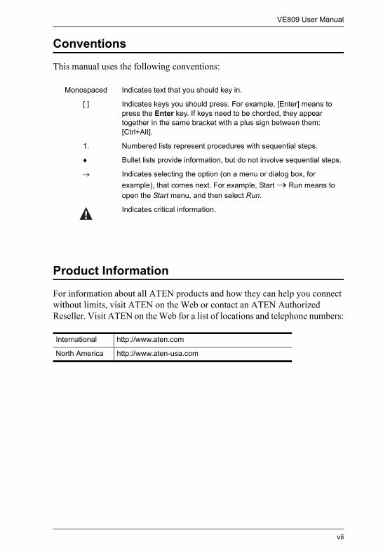
Conventions
This manual uses the following conventions:
Product Information
For information about all ATEN products and how they can help you connect without limits, visit ATEN on the Web or contact an ATEN Authorized Reseller. Visit ATEN on the Web for a list of locations and telephone numbers:
Monospaced Indicates text that you should key in.
[ ] Indicates keys you should press. For example, [Enter] means to press the Enter key. If keys need to be chorded, they appear together in the same bracket with a plus sign between them: [Ctrl+Alt].
1. Numbered lists represent procedures with sequential steps.
♦ Bullet lists provide information, but do not involve sequential steps.
→ Indicates selecting the option (on a menu or dialog box, for example), that comes next. For example, Start → Run means to open the Start menu, and then select Run.
Indicates critical information.
International http://www.aten.com
North America http://www.aten-usa.com
vii
Chapter 1Introduction
Overview
The VE809 HDMI Wireless Extender extends your HDMI display up to 30m* from the HDMI source using wireless technology. Easily connect two HDMI devices to an HDTV wirelessly with crystal clear image quality capable of streaming Full 1080p with 5.1 channel digital audio and 3D technology. The IR remote control allows you to switch between HDMI source devices from the receiver side, remotely; and allows you to watch a local and wirelessly connected HDTV- simultaneously. The VE809 consists of a wireless audio/video transmitter and receiver. Consolidate your HDMI electronics and use the VE809 as a wireless 2-port HDMI switch to connect remote devices such as Blu-ray players and HD Cable boxes to design your own custom wireless entertainment space.
* Distance may vary depending on the actual environment; solid objects such as steel, concrete, or brick may cause interference and shorten the transmission distance.
1
1. Introduction
Features
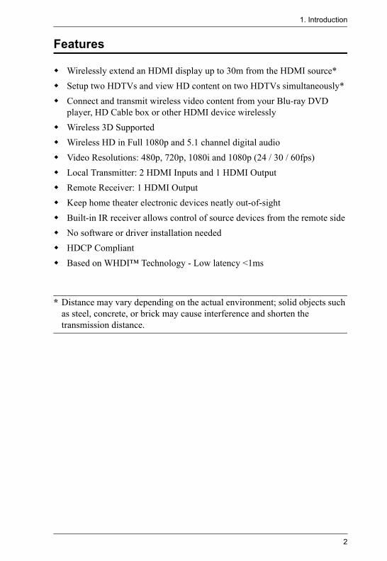
Wirelessly extend an HDMI display up to 30m from the HDMI source*Setup two HDTVs and view HD content on two HDTVs simultaneously*Connect and transmit wireless video content from your Blu-ray DVD player, HD Cable box or other HDMI device wirelesslyWireless 3D SupportedWireless HD in Full 1080p and 5.1 channel digital audioVideo Resolutions: 480p, 720p, 1080i and 1080p (24 / 30 / 60fps)Local Transmitter: 2 HDMI Inputs and 1 HDMI OutputRemote Receiver: 1 HDMI OutputKeep home theater electronic devices neatly out-of-sightBuilt-in IR receiver allows control of source devices from the remote sideNo software or driver installation neededHDCP CompliantBased on WHDI™ Technology - Low latency <1ms
* Distance may vary depending on the actual environment; solid objects such as steel, concrete, or brick may cause interference and shorten the transmission distance.
2
VE809 User Manual
Requirements
Source DeviceHDMI Type A output connector
Display DeviceA display device or receiver with an HDMI Type A input connector
3
1. Introduction
Components
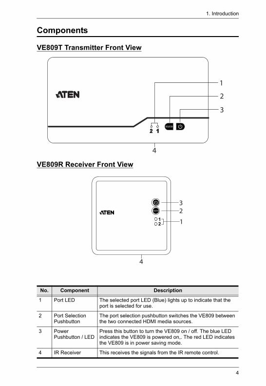
VE809T Transmitter Front View
VE809R Receiver Front View
No. Component Description
1 Port LED The selected port LED (Blue) lights up to indicate that the port is selected for use.
2 Port Selection Pushbutton
The port selection pushbutton switches the VE809 between the two connected HDMI media sources.
3 Power Pushbutton / LED
Press this button to turn the VE809 on / off. The blue LED indicates the VE809 is powered on,. The red LED indicates the VE809 is in power saving mode.
4 IR Receiver This receives the signals from the IR remote control.
1
2
3
4
4
32
1
4
VE809 User Manual
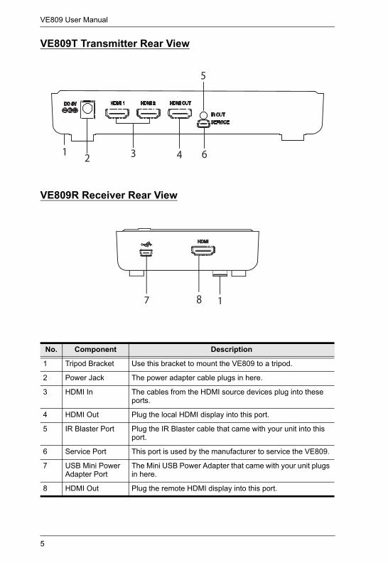
VE809T Transmitter Rear View
VE809R Receiver Rear View
No. Component Description
1 Tripod Bracket Use this bracket to mount the VE809 to a tripod.
2 Power Jack The power adapter cable plugs in here.
3 HDMI In The cables from the HDMI source devices plug into these ports.
4 HDMI Out Plug the local HDMI display into this port.
5 IR Blaster Port Plug the IR Blaster cable that came with your unit into this port.
6 Service Port This port is used by the manufacturer to service the VE809.
7 USB Mini Power Adapter Port
The Mini USB Power Adapter that came with your unit plugs in here.
8 HDMI Out Plug the remote HDMI display into this port.
432
5
61
7 8 1
5
1. Introduction
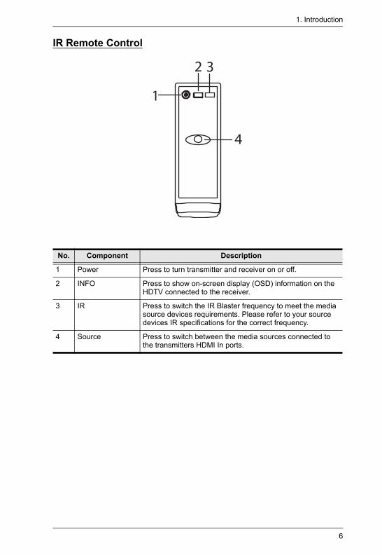
IR Remote Control
No. Component Description
1 Power Press to turn transmitter and receiver on or off.
2 INFO Press to show on-screen display (OSD) information on the HDTV connected to the receiver.
3 IR Press to switch the IR Blaster frequency to meet the media source devices requirements. Please refer to your source devices IR specifications for the correct frequency.
4 Source Press to switch between the media sources connected to the transmitters HDMI In ports.
1
2 3
4
6
Chapter 2Hardware Setup
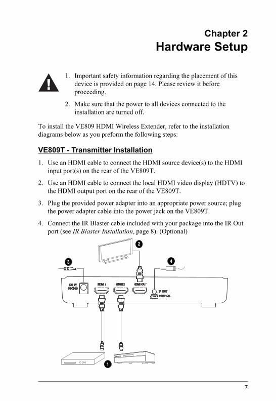
To install the VE809 HDMI Wireless Extender, refer to the installation diagrams below as you preform the following steps:
VE809T - Transmitter Installation1. Use an HDMI cable to connect the HDMI source device(s) to the HDMI
input port(s) on the rear of the VE809T.
2. Use an HDMI cable to connect the local HDMI video display (HDTV) to the HDMI output port on the rear of the VE809T.
3. Plug the provided power adapter into an appropriate power source; plug the power adapter cable into the power jack on the VE809T.
4. Connect the IR Blaster cable included with your package into the IR Out port (see IR Blaster Installation, page 8). (Optional)
1. Important safety information regarding the placement of this device is provided on page 14. Please review it before proceeding.
2. Make sure that the power to all devices connected to the installation are turned off.
1
2
3 4
7
2. Hardware Setup
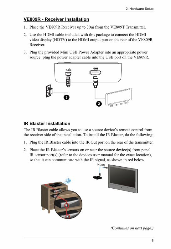
VE809R - Receiver Installation1. Place the VE809R Receiver up to 30m from the VE809T Transmitter.
2. Use the HDMI cable included with this package to connect the HDMI video display (HDTV) to the HDMI output port on the rear of the VE809R Receiver.
3. Plug the provided Mini USB Power Adapter into an appropriate power source; plug the power adapter cable into the USB port on the VE809R.
IR Blaster InstallationThe IR Blaster cable allows you to use a source device’s remote control from the receiver side of the installation. To install the IR Blaster, do the following:
1. Plug the IR Blaster cable into the IR Out port on the rear of the transmitter.
2. Place the IR Blaster’s sensors on or near the source device(s) front panel IR sensor port(s) (refer to the devices user manual for the exact location), so that it can communicate with the IR signal, as shown in red below.
(Continues on next page.)
2
3
8
VE809 User Manual
(Continued from previous page.)
3. Adjust the IR Blasters’ sensors until the remote control can be used effectively from the receiver side of the installation
4. For IR Blaster operational instructions, see IR Blaster, page 12, for details.
Note: The IR sensor supports 36KHz ~ 56KHz (NEC, RC5, RC6) remote signal protocols. Therefore, it is possible that some devices may not be supported for use.
9
Chapter 3Operation
Overview
This chapter explains how to operate the VE809 HDMI Wireless Extender, IR Blaster, IR Remote control, and EDID management.
Basic OperationAfter installing the hardware, to begin using the VE809 HDMI Wireless Extender, refer to the instructions below, and do the following:
1. Power On the Transmitter and Receiver.
2. The blue Power LED blinks on the Transmitter and Receiver until both units are wirelessly connected. It may take up to 20 seconds to establish the wireless connection.
3. From the Receiver side, turn the TV on and select the TV’s HDMI input source for the VE809 Receiver’s connection.
4. From the Transmitter, turn on the source device(s) and press the Source button (on top of the unit or from the remote control) to select the source device you would like to use: HDMI 1 or HDMI 2.
5. With the Power LED on both units solid blue, video from the selected source device will be broadcast on the remote HDTV connected to the Receiver.
Note: If you don’t get a display on the TV connected to the Receiver, press INFO on the VE809’s remote control , then refer to the on-screen display (OSD) information, and see Troubleshooting, page 18 to resolve the issue.
10
VE809 User Manual
PowerTo establish the best resolution for connected displays*, the VE809 will cause a normal short signal disruption to occur:
If both HDMI TVs and VE809T/VE809R units are on:Powering off and then on the local HDMI TV will cause the remote HDMI display signal to turn off for 5-10 seconds.Powering off and then on the remote HDMI TV will cause the local HDMI display signal to turn off for 5-10 seconds.Powering off the VE809 Transmitter or Receiver will cause the remote HDMI display signal to turn off, and local HDMI display signal to turn off for 5-10 seconds.Powering off and then on the VE809 Transmitter or Receiver will cause the local HDMI display signal to turn off for 5-10 seconds.
*For more information see EDID Management, page 13, for details.
11
3. Operation
IR BlasterThe IR Blaster allows you to use your HDMI source device's remote control from the TV connected wirelessly. To use the HDMI source device's remote control, install the IR Blaster (see IR Blaster Installation, page 8), and point the HDMI source device's remote control at the VE809R Receiver. The signal will be sent through the IR Blaster to the HDMI source device. If you experience problems using an HDMI source device’s remote control, you may need to change the IR frequency to meet the source device’s IR specifications (See Troubleshooting, page 18, for details).
IR Remote ControlThe VE809’s IR remote control has four buttons, used for:
Power
Press this button to power on/off the Transmitter or Receiver. When either unit is powered on via remote control, and a good wireless connection is established, the other unit will power on as well. This allows you to wirelessly power on both units, from either side.
IR
Press this button to change the RF frequency for an HDMI source device’s remote control, so that it can be used from the VE809R Receiver. Refer to your source devices user manual for the correct frequency, then change the VE809’s setting to match it.
INFO
Press this button to view status information about your current setup, displayed on the HDTV connected to the Receiver. This allows you to view and troubleshoot any issues. After pressing the INFO button, see Troubleshooting, page 18 for information on the message being displayed.
Source
Press this button to switch between the HDMI media sources connected to the Transmitter.
12
VE809 User Manual
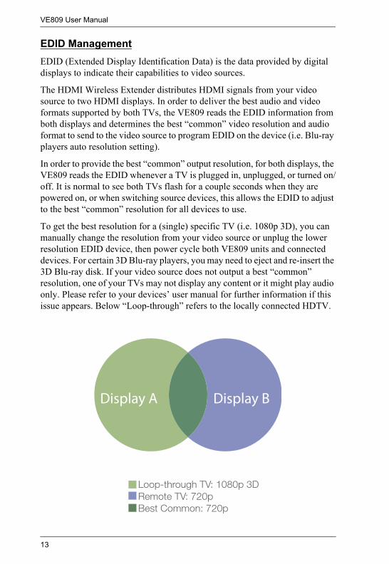
EDID ManagementEDID (Extended Display Identification Data) is the data provided by digital displays to indicate their capabilities to video sources.
The HDMI Wireless Extender distributes HDMI signals from your video source to two HDMI displays. In order to deliver the best audio and video formats supported by both TVs, the VE809 reads the EDID information from both displays and determines the best “common” video resolution and audio format to send to the video source to program EDID on the device (i.e. Blu-ray players auto resolution setting).
In order to provide the best “common” output resolution, for both displays, the VE809 reads the EDID whenever a TV is plugged in, unplugged, or turned on/off. It is normal to see both TVs flash for a couple seconds when they are powered on, or when switching source devices, this allows the EDID to adjust to the best “common” resolution for all devices to use.
To get the best resolution for a (single) specific TV (i.e. 1080p 3D), you can manually change the resolution from your video source or unplug the lower resolution EDID device, then power cycle both VE809 units and connected devices. For certain 3D Blu-ray players, you may need to eject and re-insert the 3D Blu-ray disk. If your video source does not output a best “common” resolution, one of your TVs may not display any content or it might play audio only. Please refer to your devices’ user manual for further information if this issue appears. Below “Loop-through” refers to the locally connected HDTV.
13
Appendix
Safety Instructions
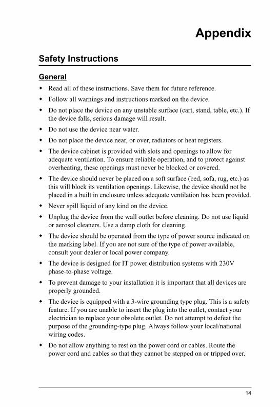
GeneralRead all of these instructions. Save them for future reference.Follow all warnings and instructions marked on the device.Do not place the device on any unstable surface (cart, stand, table, etc.). If the device falls, serious damage will result.Do not use the device near water.Do not place the device near, or over, radiators or heat registers.The device cabinet is provided with slots and openings to allow for adequate ventilation. To ensure reliable operation, and to protect against overheating, these openings must never be blocked or covered.The device should never be placed on a soft surface (bed, sofa, rug, etc.) as this will block its ventilation openings. Likewise, the device should not be placed in a built in enclosure unless adequate ventilation has been provided.Never spill liquid of any kind on the device.Unplug the device from the wall outlet before cleaning. Do not use liquid or aerosol cleaners. Use a damp cloth for cleaning.The device should be operated from the type of power source indicated on the marking label. If you are not sure of the type of power available, consult your dealer or local power company.The device is designed for IT power distribution systems with 230V phase-to-phase voltage.To prevent damage to your installation it is important that all devices are properly grounded.The device is equipped with a 3-wire grounding type plug. This is a safety feature. If you are unable to insert the plug into the outlet, contact your electrician to replace your obsolete outlet. Do not attempt to defeat the purpose of the grounding-type plug. Always follow your local/national wiring codes.Do not allow anything to rest on the power cord or cables. Route the power cord and cables so that they cannot be stepped on or tripped over.
14
VE809 User Manual
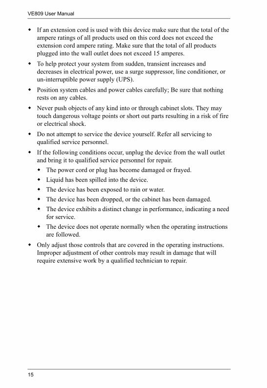
If an extension cord is used with this device make sure that the total of the ampere ratings of all products used on this cord does not exceed the extension cord ampere rating. Make sure that the total of all products plugged into the wall outlet does not exceed 15 amperes.To help protect your system from sudden, transient increases and decreases in electrical power, use a surge suppressor, line conditioner, or un-interruptible power supply (UPS).Position system cables and power cables carefully; Be sure that nothing rests on any cables.Never push objects of any kind into or through cabinet slots. They may touch dangerous voltage points or short out parts resulting in a risk of fire or electrical shock.Do not attempt to service the device yourself. Refer all servicing to qualified service personnel.If the following conditions occur, unplug the device from the wall outlet and bring it to qualified service personnel for repair.
The power cord or plug has become damaged or frayed.Liquid has been spilled into the device.The device has been exposed to rain or water.The device has been dropped, or the cabinet has been damaged.The device exhibits a distinct change in performance, indicating a need for service.The device does not operate normally when the operating instructions are followed.
Only adjust those controls that are covered in the operating instructions. Improper adjustment of other controls may result in damage that will require extensive work by a qualified technician to repair.
15
Appendix
Technical SupportInternational
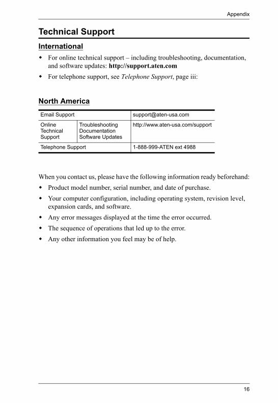
For online technical support – including troubleshooting, documentation, and software updates: http://support.aten.comFor telephone support, see Telephone Support, page iii:
North America
When you contact us, please have the following information ready beforehand:Product model number, serial number, and date of purchase.Your computer configuration, including operating system, revision level, expansion cards, and software.Any error messages displayed at the time the error occurred.The sequence of operations that led up to the error.Any other information you feel may be of help.
Email Support [email protected]
Online Technical Support
TroubleshootingDocumentationSoftware Updates
http://www.aten-usa.com/support
Telephone Support 1-888-999-ATEN ext 4988
16
VE809 User Manual
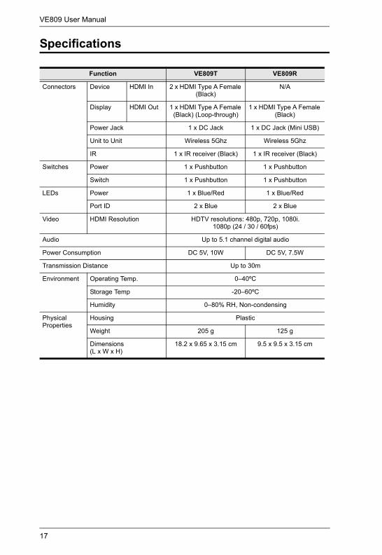
Specifications
Function VE809T VE809R
Connectors Device HDMI In 2 x HDMI Type A Female (Black)
N/A
Display HDMI Out 1 x HDMI Type A Female (Black) (Loop-through)
1 x HDMI Type A Female (Black)
Power Jack 1 x DC Jack 1 x DC Jack (Mini USB)
Unit to Unit Wireless 5Ghz Wireless 5Ghz
IR 1 x IR receiver (Black) 1 x IR receiver (Black)
Switches Power 1 x Pushbutton 1 x Pushbutton
Switch 1 x Pushbutton 1 x Pushbutton
LEDs Power 1 x Blue/Red 1 x Blue/Red
Port ID 2 x Blue 2 x Blue
Video HDMI Resolution HDTV resolutions: 480p, 720p, 1080i.1080p (24 / 30 / 60fps)
Audio Up to 5.1 channel digital audio
Power Consumption DC 5V, 10W DC 5V, 7.5W
Transmission Distance Up to 30m
Environment Operating Temp. 0–40ºC
Storage Temp -20–60ºC
Humidity 0–80% RH, Non-condensing
Physical Properties
Housing Plastic
Weight 205 g 125 g
Dimensions(L x W x H)
18.2 x 9.65 x 3.15 cm 9.5 x 9.5 x 3.15 cm
17
Appendix
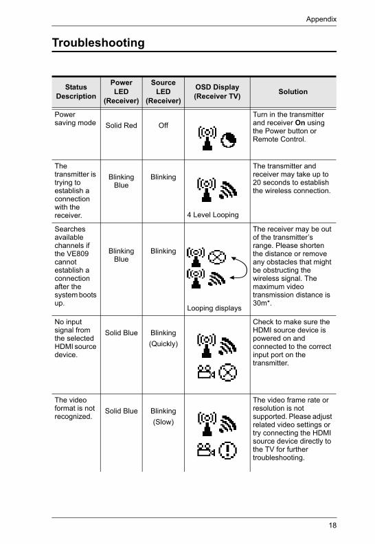
Troubleshooting
Status Description
Power LED
(Receiver)
Source LED
(Receiver)
OSD Display(Receiver TV) Solution
Power saving mode Solid Red Off
Turn in the transmitter and receiver On using the Power button or Remote Control.
The transmitter is trying to establish a connection with the receiver.
Blinking Blue
Blinking
4 Level Looping
The transmitter and receiver may take up to 20 seconds to establish the wireless connection.
Searches available channels if the VE809 cannot establish a connection after the system boots up.
Blinking Blue
Blinking
Looping displays
The receiver may be out of the transmitter’s range. Please shorten the distance or remove any obstacles that might be obstructing the wireless signal. The maximum video transmission distance is 30m*.
No input signal from the selected HDMI source device.
Solid Blue Blinking (Quickly)
Check to make sure the HDMI source device is powered on and connected to the correct input port on the transmitter.
The video format is not recognized.
Solid Blue Blinking(Slow)
The video frame rate or resolution is not supported. Please adjust related video settings or try connecting the HDMI source device directly to the TV for further troubleshooting.
18
VE809 User Manual
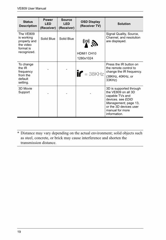
* Distance may vary depending on the actual environment; solid objects such as steel, concrete, or brick may cause interference and shorten the transmission distance.
The VE809 is working properly and the video format is recognized.
Solid Blue Solid Blue
HDMI1 CH101280x1024
Signal Quality, Source, Channel, and resolution are displayed.
To change the IR frequency from the default setting.
- -Press the IR button on the remote control to change the IR frequency.(38KHz, 40KHz, or 33KHz)
3D Movie Support - - -
3D is supported through the VE809 on all 3D capable TVs and devices. see EDID Management, page 13, or the 3D devices user manual for more information.
Status Description
Power LED
(Receiver)
Source LED
(Receiver)
OSD Display(Receiver TV) Solution
19
Appendix
Limited Warranty
IN NO EVENT SHALL THE DIRECT VENDOR'S LIABILITY EXCEED THE PRICE PAID FOR THE PRODUCT FROM DIRECT, INDIRECT, SPECIAL, INCIDENTAL, OR CONSEQUENTIAL DAMAGES RESULTING FROM THE USE OF THE PRODUCT, DISK, OR ITS DOCUMENTATION.
The direct vendor makes no warranty or representation, expressed, implied, or statutory with respect to the contents or use of this documentation, and especially disclaims its quality, performance, merchantability, or fitness for any particular purpose.
The direct vendor also reserves the right to revise or update the device or documentation without obligation to notify any individual or entity of such revisions, or update. For further inquiries, please contact your direct vendor.
20