Embed Size (px)
Citation preview
7/29/2019 HDL PPT.ppsx
http://slidepdf.com/reader/full/hdl-pptppsx 1/91
Wednesday, September 11,20131
GOOD MORNING
Chapter 3 : Behavioral Modeling
Chapter 2 : Dataflow Modeling

7/29/2019 HDL PPT.ppsx
http://slidepdf.com/reader/full/hdl-pptppsx 2/91
entity halfadder is
port (a: in bit; b: in bit; s: out bit; c: out bit);
end halfadder;
architecture HA_DtFl of halfadder is
--The architecture has no process, component, cmos,
begin
s <= a xor b;
c <= a and b;end HA_DtFl;
module halfadder (a,b,s,c);
input a;
input b;
output s;
output c;
assign s = a ^ b;
assign c = a & b;
/* The module has no always, gates such as and, cmos*/
endmodule
Data-Flow Description
Wednesday, September 11,20132
7/29/2019 HDL PPT.ppsx
http://slidepdf.com/reader/full/hdl-pptppsx 3/91
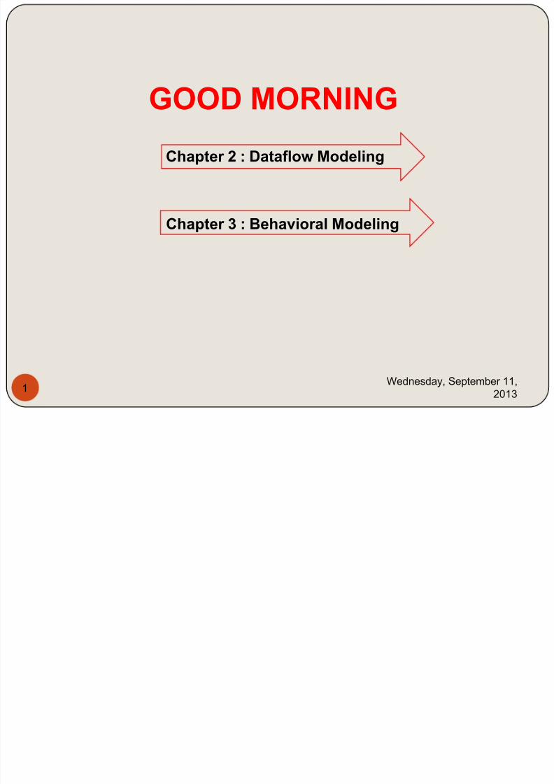
Structural Descriptionarchitecture Half_add of system is
component xor2
port(I1, I2 : in bit; O1 : out bit);end component;
component and2
port(I1, I2 : in bit; O1 : out bit);
end component;
begin
X1 : xor2 port map (a, b, sum);A1 : and2 port map (a, b, cout);
end Half_add;
module system(a, b, sum, cout);
input a, b;
output sum, cout;xor X1(sum, a, b);
//The above statement is EXCLUSIVE-OR gate
and a1(cout, a, b);
//The above statement is AND gate
endmodule
entity system is
port (I1: in bit; I2: in bit; O1: out bit; c: out
bit);end system;
Wednesday, September 11,20133
7/29/2019 HDL PPT.ppsx
http://slidepdf.com/reader/full/hdl-pptppsx 4/91
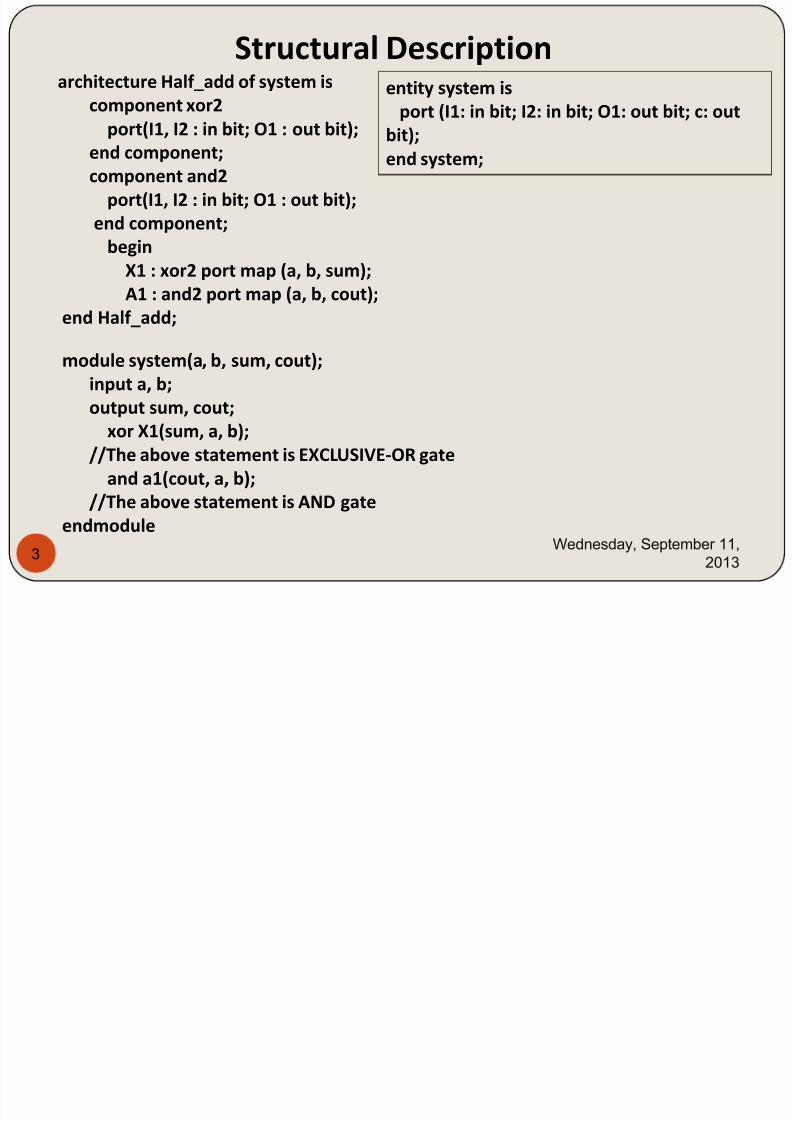
Behavioral Descriptionarchitecture behave_ex of half_add is
begin
process (I1, I2)begin
O1 <= I1 xor I2 after 10 ns;
O2 <= I1 and I2 after 10 ns;
end process;
end behave_ex;
module half_add (I1, I2, O1, O2);
input I1, I2;
output O1, O2;
reg O1, O2;
always @(I1, I2)begin
#10 O1 = I1 ^ I2;
#10 O2 = I1& I2;
end
endmodule
Wednesday, September 11,20134
7/29/2019 HDL PPT.ppsx
http://slidepdf.com/reader/full/hdl-pptppsx 5/91
Wednesday, September 11,
20135
7/29/2019 HDL PPT.ppsx
http://slidepdf.com/reader/full/hdl-pptppsx 6/91
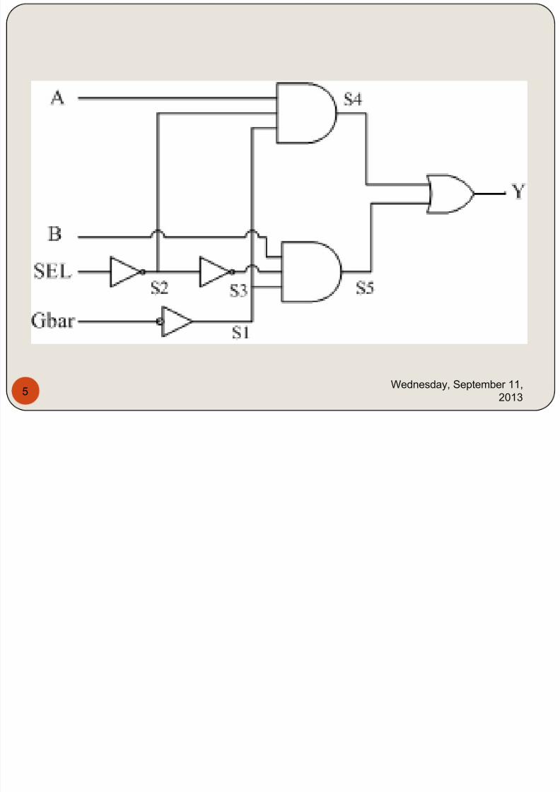
library IEEE;
use IEEE.STD_LOGIC_1164.ALL;
entity mux2x1 is
port (A, B, SEL, Gbar : in std_logic;Y : out std_logic);
end mux2x1;
architecture MUX_DF of mux2x1 is
signal S1, S2, S3, S4, S5 : std_logic;
Begin
st1: Y <= S4 or S5 after 7 ns;
st2: S4 <= A and S2 and S1 after 7 ns;
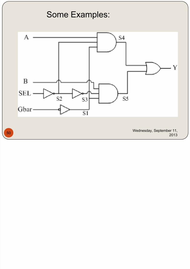
st3: S5 <= B and S3 and S1 after 7 ns;st4: S2 <= not SEL after 7 ns;
st5: S3 <= not S2 after 7 ns;
st6: S1 <= not Gbar after 7 ns;
end MUX_DF;Wednesday, September 11,
20136
7/29/2019 HDL PPT.ppsx
http://slidepdf.com/reader/full/hdl-pptppsx 7/91
architecture MUX_bh of MUX_if is
begin
process (SEL, A, B, Gbar)
variable temp : std_logic;begin
if Gbar = '0' then
if SEL = '1' then
temp := B;
elsetemp := A;
end if;
Y <= temp;
else
Y <= 'Z';end if;
end process;
end MUX_bh; Wednesday, September 11,
20137
7/29/2019 HDL PPT.ppsx
http://slidepdf.com/reader/full/hdl-pptppsx 8/91
module mux2x1 (A, B, SEL, Gbar, Y);
input A, B, SEL, Gbar;output Y;
and #7 (S4, A, S2, S1);
or #7 (Y, S4, S5);
and #7 (S5, B, S3, S1);
not #7 (S2, SEL);
not #7 (S3, S2);
not #7 (S1, Gbar);endmodule
Wednesday, September 11,
20138
7/29/2019 HDL PPT.ppsx
http://slidepdf.com/reader/full/hdl-pptppsx 9/91
module mux2x1 (A, B, SEL, Gbar, Y);
input A, B, SEL, Gbar;
output Y;wire S1, S2, S3, S4, S5;
/* Assume 7 time units delay for all and, or, not.
In Verilog we cannot use specific time units,
such as nanoseconds. The delay here isexpressed in simulation screen units. */
assign #7 Y = S4 | S5; //st1
assign #7 S4 = A & S2 & S1; //st2
assign #7 S5 = B & S3 & S1; //st3
assign #7 S2 = ~ SEL; //st4
assign #7 S3 = ~ S2; //st5
assign #7 S1 = ~ Gbar; //st6
endmoduleWednesday, September 11,
20139
7/29/2019 HDL PPT.ppsx
http://slidepdf.com/reader/full/hdl-pptppsx 10/91
module mux2x1 (A, B, SEL, Gbar, Y);
input A, B, SEL, Gbar;
output Y;
reg Y;always @ (SEL, A, B, Gbar)
begin
if (Gbar == 1)
Y = 1'bz;
elsebegin
if (SEL)
Y = B;
else
Y = A;
end
end
endmoduleWednesday, September 11,
201310
7/29/2019 HDL PPT.ppsx
http://slidepdf.com/reader/full/hdl-pptppsx 11/91
architecture mux_str of mux2x1 is
component and3
port (I1, I2, I3 : in std_logic; O1 : out std_logic);
end component;
component or2port (I1, I2 : in std_logic; O1 : out std_logic);
end component;
component Inv
port (I1 : in std_logic; O1 : out std_logic);
end component;
signal S1, S2, S3, S4, S5 : std_logic;
Begin
A1 : and3 port map (A,S2, S1, S4);
A2 : and3 port map (B,S3, S1, S5);IV1 : Inv port map (SEL, S2);
IV2 : Inv port map (Gbar, S1);
IV3 : Inv port map (S2, S3);
or1 : or2 port map (S4, S5, Y);
end mux_str;Wednesday, September 11,
201311
7/29/2019 HDL PPT.ppsx
http://slidepdf.com/reader/full/hdl-pptppsx 12/91
entity Inverter is
Port (y : out std_logic; a: in std_logic );--VHDL does not have built-in
switch-level
end Inverter;architecture Invert_switch of Inverter is
component nmos
--nmos is one of the key words for switch-level.
port (O1: out std_logic; I1, I2 : in std_logic);
end component;constant vdd: std_logic := '1';
constant gnd : std_logic:= '0';
begin
p1 : pmos port map (y, vdd, a);
n1: nmos port map (y, gnd, a);end Invert_switch;
Wednesday, September 11,
201312
7/29/2019 HDL PPT.ppsx
http://slidepdf.com/reader/full/hdl-pptppsx 13/91
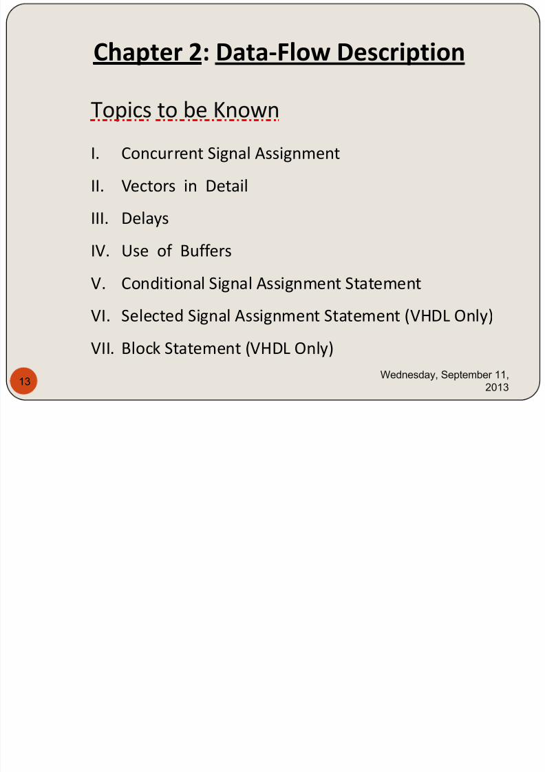
Chapter 2: Data-Flow Description
Topics to be Known
I. Concurrent Signal Assignment
II. Vectors in Detail
III. Delays
IV. Use of Buffers
V. Conditional Signal Assignment Statement
VI. Selected Signal Assignment Statement (VHDL Only)
VII. Block Statement (VHDL Only)
Wednesday, September 11,
201313
7/29/2019 HDL PPT.ppsx
http://slidepdf.com/reader/full/hdl-pptppsx 14/91
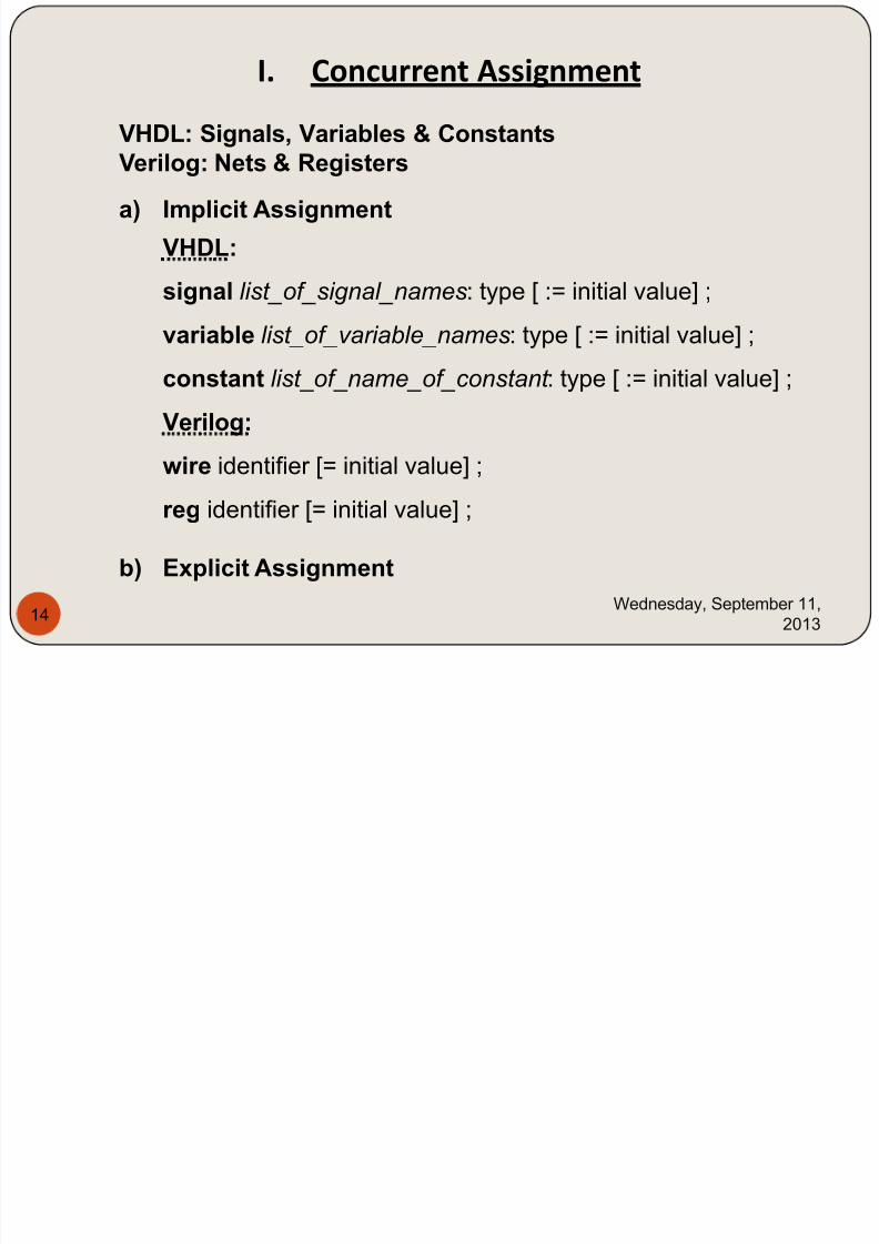
I. Concurrent Assignment
a) Implicit Assignment
VHDL:
signal list_of_signal_names: type [ := initial value] ;
variable list_of_variable_names: type [ := initial value] ;
constant list _ of _ name_of_constant : type [ := initial value] ;
Verilog:
wire identifier [= initial value] ;
reg identifier [= initial value] ;
b) Explicit Assignment
VHDL: Signals, Variables & Constants
Verilog: Nets & Registers
Wednesday, September 11,
201314
7/29/2019 HDL PPT.ppsx
http://slidepdf.com/reader/full/hdl-pptppsx 15/91
Wednesday, September 11,
201315
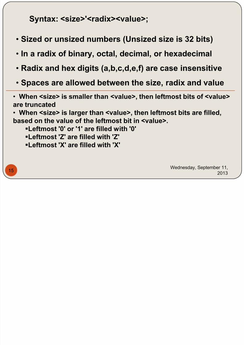
Syntax: <size>'<radix><value>;
• Sized or unsized numbers (Unsized size is 32 bits)• In a radix of binary, octal, decimal, or hexadecimal
• Radix and hex digits (a,b,c,d,e,f) are case insensitive
• Spaces are allowed between the size, radix and value• When <size> is smaller than <value>, then leftmost bits of <value>are truncated• When <size> is larger than <value>, then leftmost bits are filled,based on the value of the leftmost bit in <value>.
Leftmost '0' or '1' are filled with '0'Leftmost 'Z' are filled with 'Z'Leftmost 'X' are filled with 'X'
7/29/2019 HDL PPT.ppsx
http://slidepdf.com/reader/full/hdl-pptppsx 16/91
Wednesday, September 11,
201316
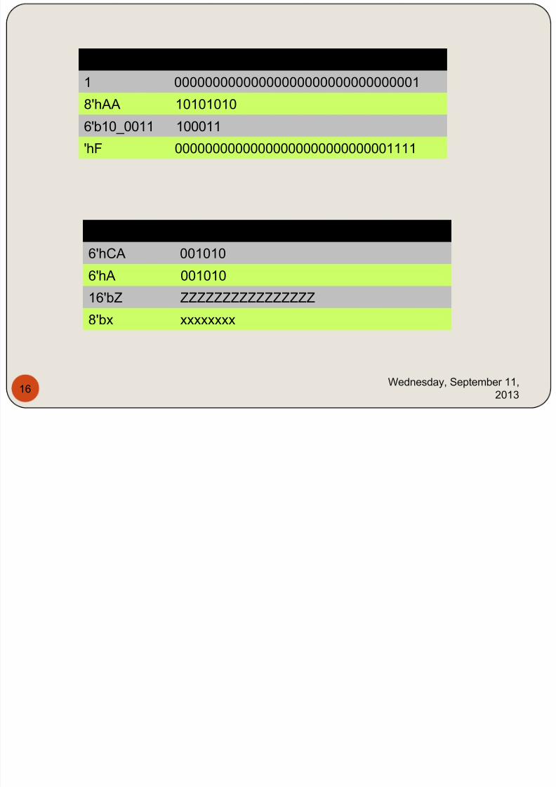
Integer Stored as
1 00000000000000000000000000000001
8'hAA 10101010
6'b10_0011 100011
'hF 00000000000000000000000000001111
Integer Stored as
6'hCA 001010
6'hA 001010
16'bZ ZZZZZZZZZZZZZZZZ
8'bx xxxxxxxx
7/29/2019 HDL PPT.ppsx
http://slidepdf.com/reader/full/hdl-pptppsx 17/91
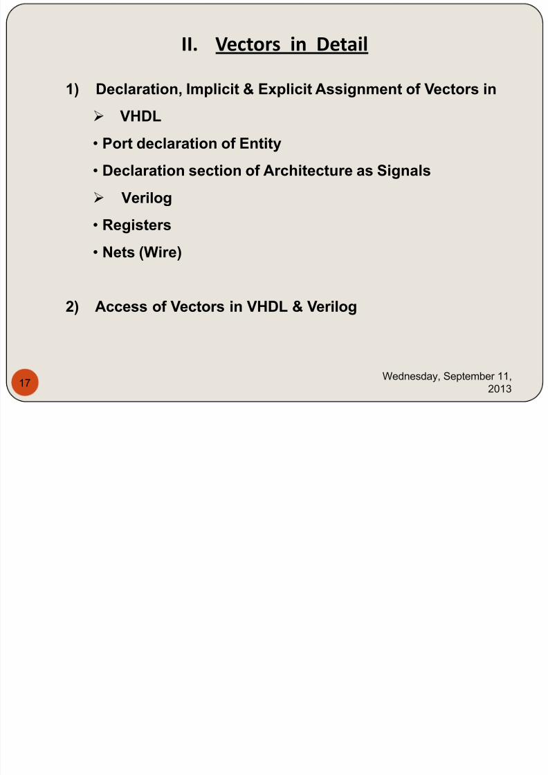
II. Vectors in Detail
1) Declaration, Implicit & Explicit Assignment of Vectors in VHDL
• Port declaration of Entity
• Declaration section of Architecture as Signals
Verilog
• Registers
• Nets (Wire)
2) Access of Vectors in VHDL & Verilog
Wednesday, September 11,
201317
7/29/2019 HDL PPT.ppsx
http://slidepdf.com/reader/full/hdl-pptppsx 18/91
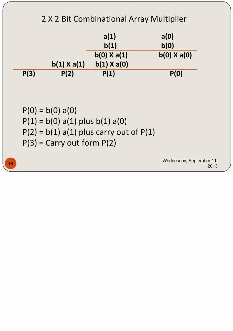
2 X 2 Bit Combinational Array Multiplier
a(1) a(0)
b(1) b(0)
b(0) X a(1) b(0) X a(0)
b(1) X a(1) b(1) X a(0)
P(3) P(2) P(1) P(0)
P(0) = b(0) a(0)
P(1) = b(0) a(1) plus b(1) a(0)P(2) = b(1) a(1) plus carry out of P(1)
P(3) = Carry out form P(2)
Wednesday, September 11,
201318
7/29/2019 HDL PPT.ppsx
http://slidepdf.com/reader/full/hdl-pptppsx 19/91
Wednesday, September 11,
201319
7/29/2019 HDL PPT.ppsx
http://slidepdf.com/reader/full/hdl-pptppsx 20/91
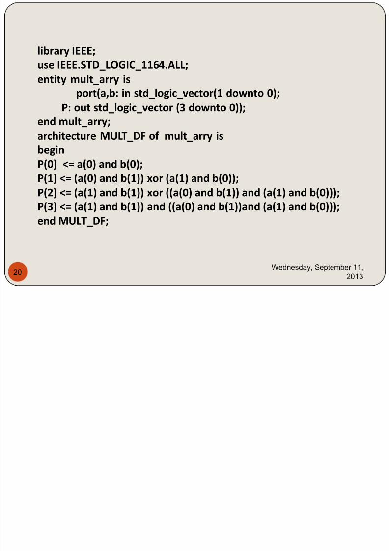
library IEEE;
use IEEE.STD_LOGIC_1164.ALL;entity mult_arry is
port(a,b: in std_logic_vector(1 downto 0);
P: out std_logic_vector (3 downto 0));
end mult_arry;
architecture MULT_DF of mult_arry isbegin
P(0) <= a(0) and b(0);
P(1) <= (a(0) and b(1)) xor (a(1) and b(0));
P(2) <= (a(1) and b(1)) xor ((a(0) and b(1)) and (a(1) and b(0)));
P(3) <= (a(1) and b(1)) and ((a(0) and b(1))and (a(1) and b(0)));end MULT_DF;
Wednesday, September 11,
201320
7/29/2019 HDL PPT.ppsx
http://slidepdf.com/reader/full/hdl-pptppsx 21/91
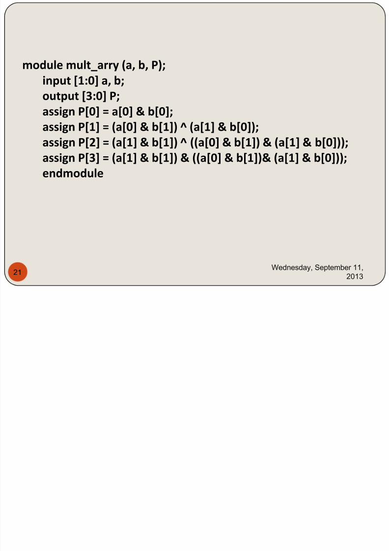
module mult_arry (a, b, P);input [1:0] a, b;
output [3:0] P;
assign P[0] = a[0] & b[0];
assign P[1] = (a[0] & b[1]) ^ (a[1] & b[0]);
assign P[2] = (a[1] & b[1]) ^ ((a[0] & b[1]) & (a[1] & b[0]));
assign P[3] = (a[1] & b[1]) & ((a[0] & b[1])& (a[1] & b[0]));
endmodule
Wednesday, September 11,
201321
7/29/2019 HDL PPT.ppsx
http://slidepdf.com/reader/full/hdl-pptppsx 22/91
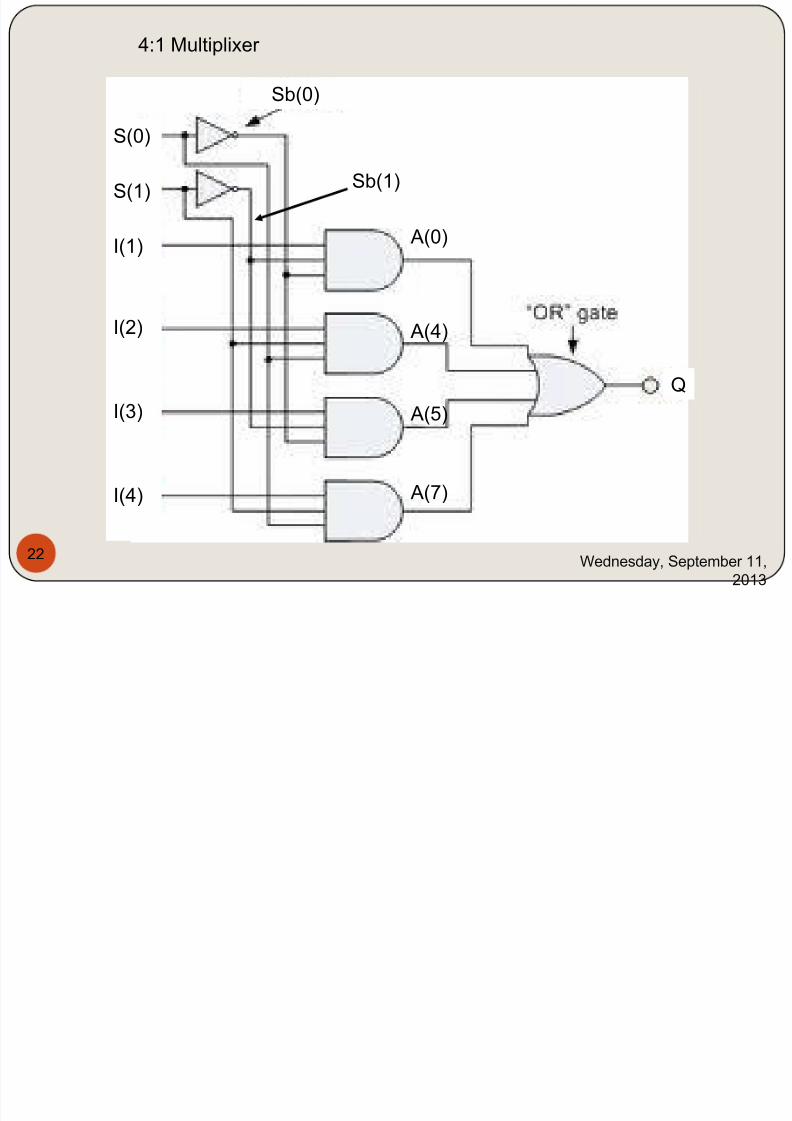
4:1 Multiplixer
S(0)
S(1)
I(1)
I(2)
I(3)
I(4)
Q
Sb(0)
Sb(1)
A(0)
A(4)
A(5)
A(7)
Wednesday, September 11,
2013
22
7/29/2019 HDL PPT.ppsx
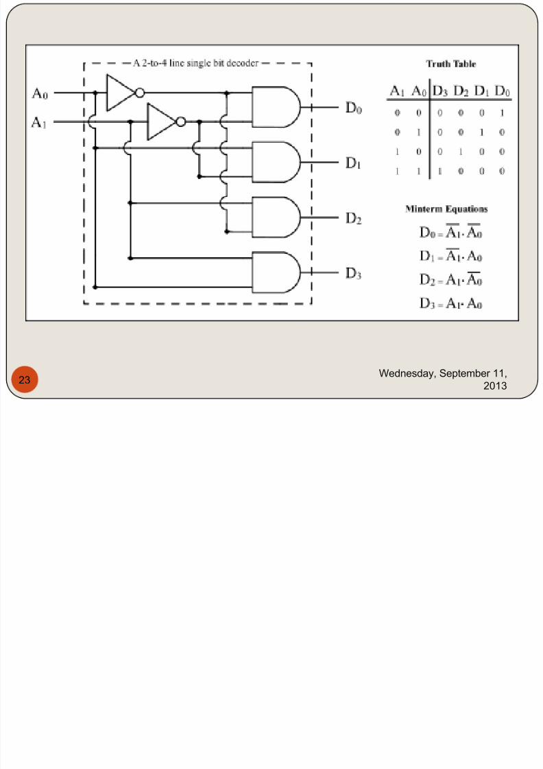
http://slidepdf.com/reader/full/hdl-pptppsx 23/91
Wednesday, September 11,
201323
7/29/2019 HDL PPT.ppsx
http://slidepdf.com/reader/full/hdl-pptppsx 24/91
Wednesday, September 11,
201324
7/29/2019 HDL PPT.ppsx
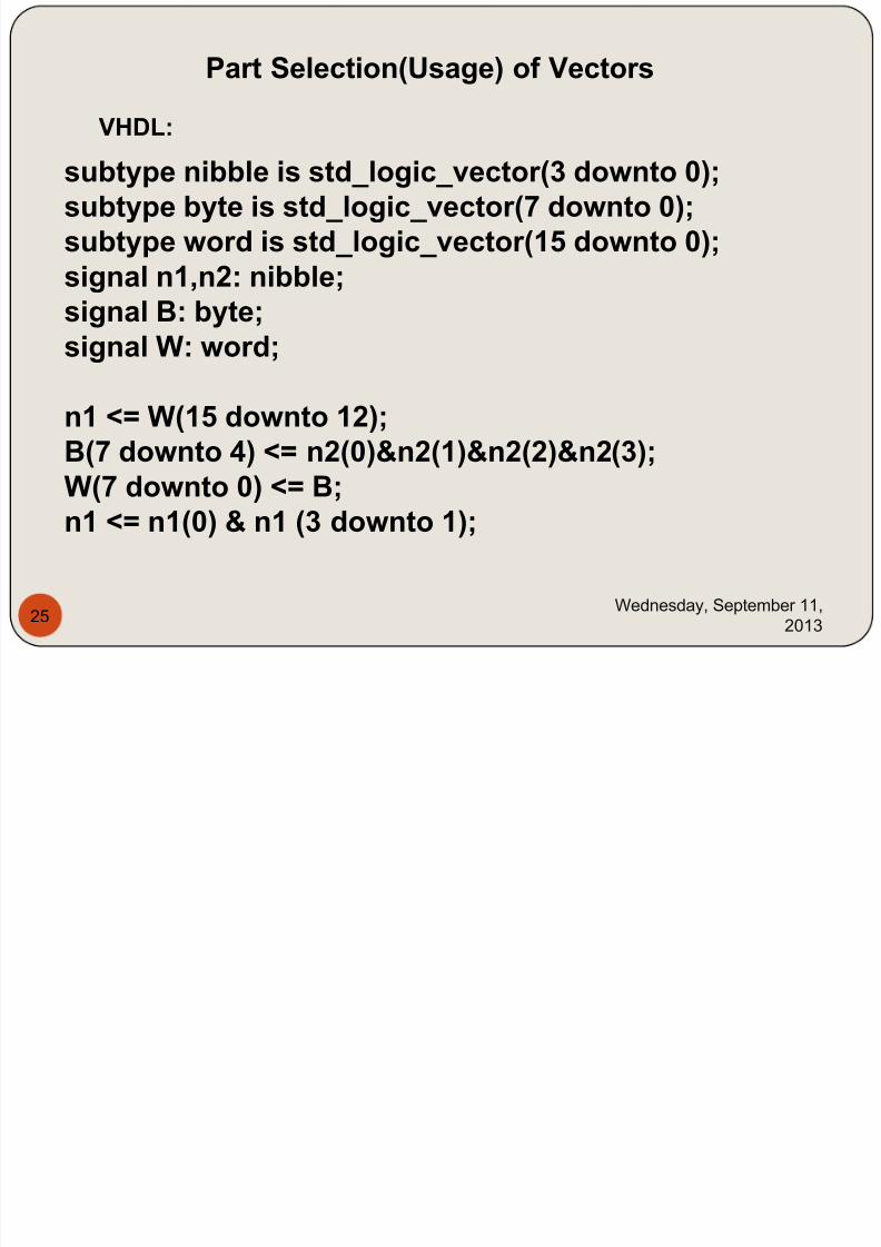
http://slidepdf.com/reader/full/hdl-pptppsx 25/91
subtype nibble is std_logic_vector(3 downto 0);subtype byte is std_logic_vector(7 downto 0);subtype word is std_logic_vector(15 downto 0);signal n1,n2: nibble;
signal B: byte;signal W: word;
n1 <= W(15 downto 12);
B(7 downto 4) <= n2(0)&n2(1)&n2(2)&n2(3);W(7 downto 0) <= B;n1 <= n1(0) & n1 (3 downto 1);
Part Selection(Usage) of Vectors
VHDL:
Wednesday, September 11,
201325
7/29/2019 HDL PPT.ppsx
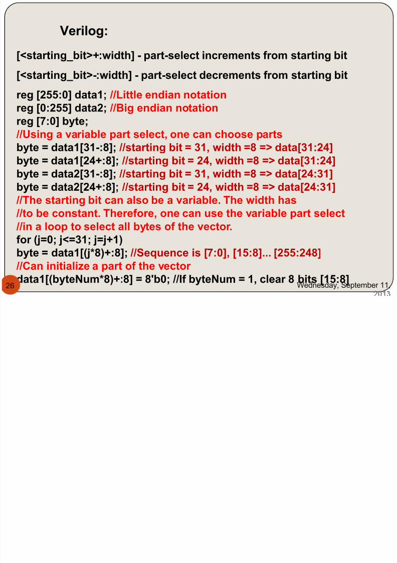
http://slidepdf.com/reader/full/hdl-pptppsx 26/91
[<starting_bit>+:width] - part-select increments from starting bit
[<starting_bit>-:width] - part-select decrements from starting bit
Verilog:
reg [255:0] data1; //Little endian notationreg [0:255] data2; //Big endian notationreg [7:0] byte;
//Using a variable part select, one can choose partsbyte = data1[31-:8]; //starting bit = 31, width =8 => data[31:24]byte = data1[24+:8]; //starting bit = 24, width =8 => data[31:24]byte = data2[31-:8]; //starting bit = 31, width =8 => data[24:31]byte = data2[24+:8]; //starting bit = 24, width =8 => data[24:31]
//The starting bit can also be a variable. The width has
//to be constant. Therefore, one can use the variable part select //in a loop to select all bytes of the vector.for (j=0; j<=31; j=j+1)byte = data1[(j*8)+:8]; //Sequence is [7:0], [15:8]... [255:248]
//Can initialize a part of the vector
data1[(byteNum*8)+:8] = 8'b0; //If byteNum = 1, clear 8 bits [15:8]Wednesday, September 11,26
7/29/2019 HDL PPT.ppsx
http://slidepdf.com/reader/full/hdl-pptppsx 27/91
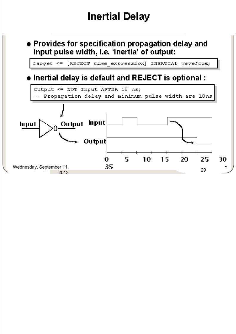
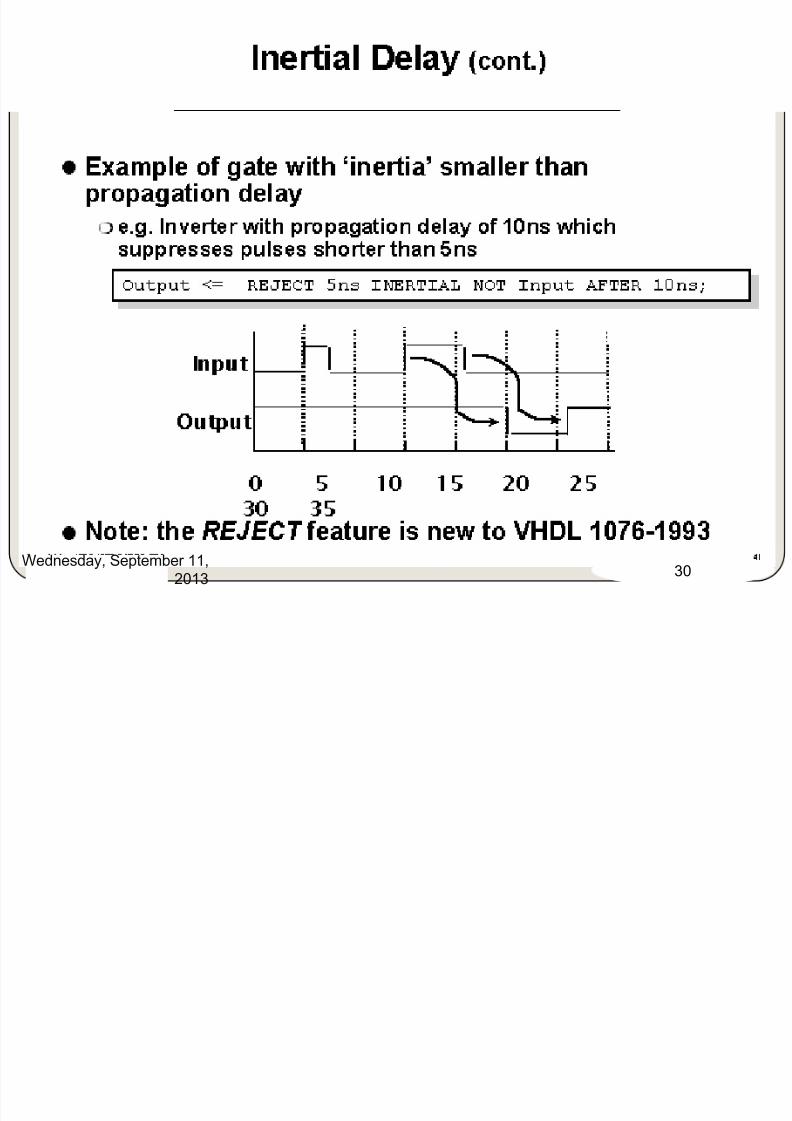
III. Delays
VHDL:
a) Transport,
b) Inertial &
c) Delta
Wednesday, September 11,
201327
7/29/2019 HDL PPT.ppsx
http://slidepdf.com/reader/full/hdl-pptppsx 28/91
Wednesday, September 11,
201328
7/29/2019 HDL PPT.ppsx
http://slidepdf.com/reader/full/hdl-pptppsx 29/91
Wednesday, September 11,2013
29
7/29/2019 HDL PPT.ppsx
http://slidepdf.com/reader/full/hdl-pptppsx 30/91
Wednesday, September 11,2013
30
7/29/2019 HDL PPT.ppsx
http://slidepdf.com/reader/full/hdl-pptppsx 31/91
Wednesday, September 11,
201331
7/29/2019 HDL PPT.ppsx
http://slidepdf.com/reader/full/hdl-pptppsx 32/91
Wednesday, September 11,2013
32
7/29/2019 HDL PPT.ppsx
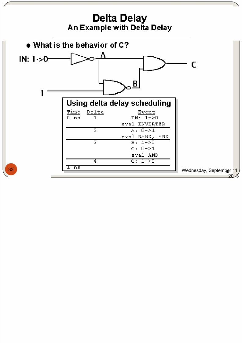
http://slidepdf.com/reader/full/hdl-pptppsx 33/91
Wednesday, September 11,2013
33
7/29/2019 HDL PPT.ppsx
http://slidepdf.com/reader/full/hdl-pptppsx 34/91
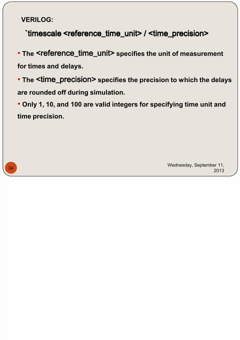
`timescale <reference_time_unit> / <time_precision> timescale <reference_time_unit> / <time_precision>
Wednesday, September 11,
201334
VERILOG:
• The <reference_time_unit> specifies the unit of measurement
for times and delays.
• The <time_precision> specifies the precision to which the delays
are rounded off during simulation.
• Only 1, 10, and 100 are valid integers for specifying time unit and
time precision.
7/29/2019 HDL PPT.ppsx
http://slidepdf.com/reader/full/hdl-pptppsx 35/91
Wednesday, September 11,
201335
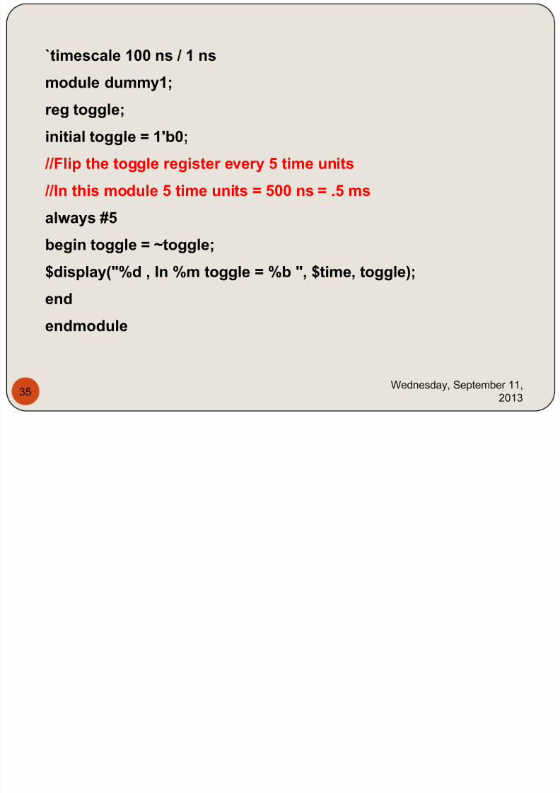
`timescale 100 ns / 1 ns
module dummy1;
reg toggle;
initial toggle = 1'b0;
//Flip the toggle register every 5 time units
//In this module 5 time units = 500 ns = .5 ms
always #5
begin toggle = ~toggle;
$display("%d , In %m toggle = %b ", $time, toggle);
end
endmodule
7/29/2019 HDL PPT.ppsx
http://slidepdf.com/reader/full/hdl-pptppsx 36/91
Wednesday, September 11,
201336
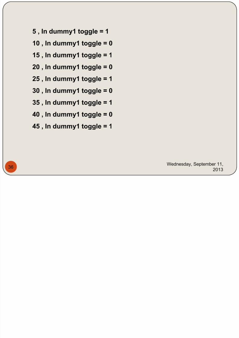
5 , In dummy1 toggle = 1
10 , In dummy1 toggle = 0
15 , In dummy1 toggle = 1
20 , In dummy1 toggle = 0
25 , In dummy1 toggle = 1
30 , In dummy1 toggle = 0
35 , In dummy1 toggle = 1
40 , In dummy1 toggle = 0
45 , In dummy1 toggle = 1
7/29/2019 HDL PPT.ppsx
http://slidepdf.com/reader/full/hdl-pptppsx 37/91
Wednesday, September 11,
201337
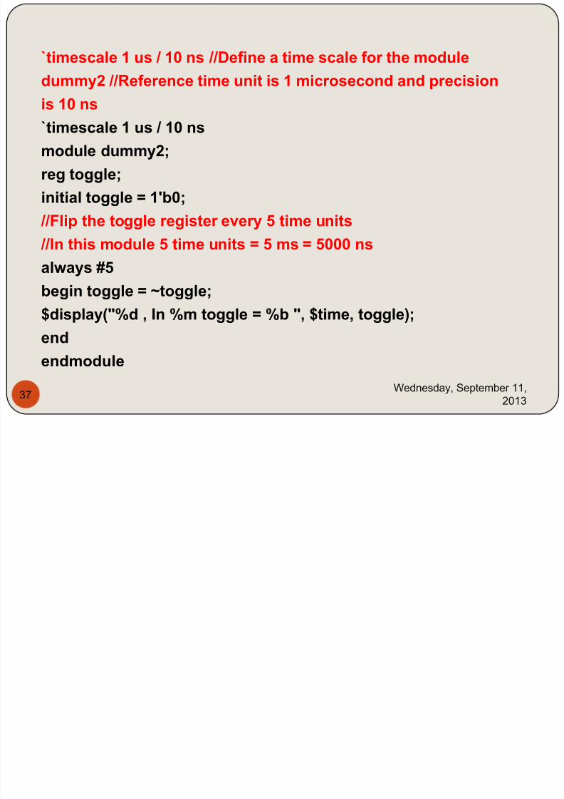
`timescale 1 us / 10 ns //Define a time scale for the module
dummy2 //Reference time unit is 1 microsecond and precision
is 10 ns`timescale 1 us / 10 ns
module dummy2;
reg toggle;
initial toggle = 1'b0; //Flip the toggle register every 5 time units
//In this module 5 time units = 5 ms = 5000 ns
always #5
begin toggle = ~toggle;$display("%d , In %m toggle = %b ", $time, toggle);
end
endmodule
7/29/2019 HDL PPT.ppsx
http://slidepdf.com/reader/full/hdl-pptppsx 38/91
Wednesday, September 11,
201338
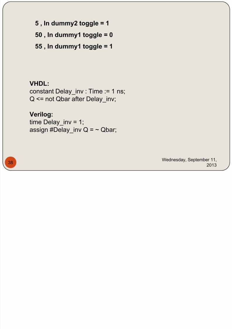
5 , In dummy2 toggle = 1
50 , In dummy1 toggle = 0
55 , In dummy1 toggle = 1
VHDL:constant Delay_inv : Time := 1 ns;
Q <= not Qbar after Delay_inv;
Verilog:
time Delay_inv = 1;assign #Delay_inv Q = ~ Qbar;
7/29/2019 HDL PPT.ppsx
http://slidepdf.com/reader/full/hdl-pptppsx 39/91
Wednesday, September 11,
201339
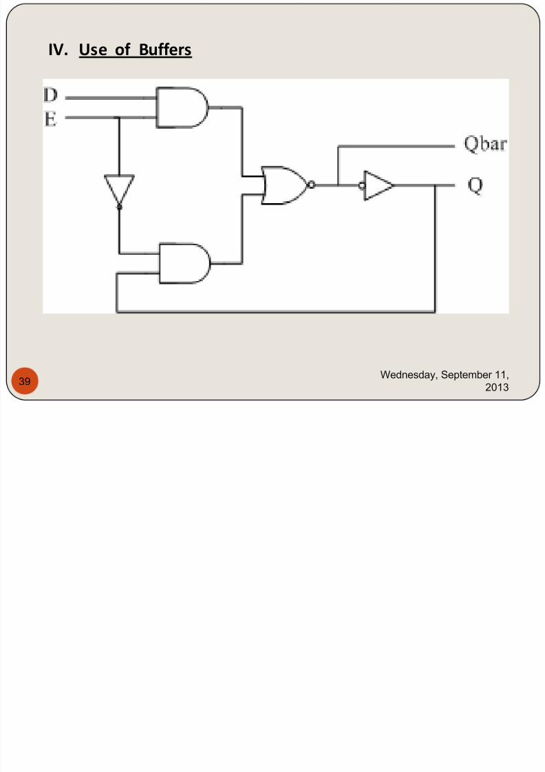
IV. Use of Buffers
7/29/2019 HDL PPT.ppsx
http://slidepdf.com/reader/full/hdl-pptppsx 40/91
Wednesday, September 11,
201340
entity D_Latch is
port (D, E : in std_logic; Q, Qbar : buffer std_logic);-- Q and Qbar are declared as buffer because they act as
--both input and output, they appear on the right and left
--hand side of signal assignment statements. inout or
-- linkage could have been used instead of buffer.
end D_Latch;
architecture DL_DtFl of D_Latch is
constant Delay_EorD : Time := 9 ns;
constant Delay_inv : Time := 1 ns;
begin
--Assume 9-ns propagation delay time between
--E or D and Qbar; and 1 ns between Qbar and Q.
Qbar <= (D and E) nor (not E and Q) after Delay_EorD;
Q <= not Qbar after Delay_inv;
end DL_DtFl;

7/29/2019 HDL PPT.ppsx
http://slidepdf.com/reader/full/hdl-pptppsx 41/91
Wednesday, September 11,
201341
module D_latch (D, E, Q, Qbar);
input D, E;
output Q, Qbar;
/* Verilog treats the ports as internal ports, so Q and Qbar are not
considered here as both input and output. If the port is connected
externally as bidirectional, then we should use inout. */
time Delay_EorD = 9;
time Delay_inv = 1;
assign #Delay_EorD Qbar = ~((E & D) | (~E & Q));
assign #Delay_inv Q = ~ Qbar;
endmodule
7/29/2019 HDL PPT.ppsx
http://slidepdf.com/reader/full/hdl-pptppsx 42/91
Wednesday, September 11,
201342
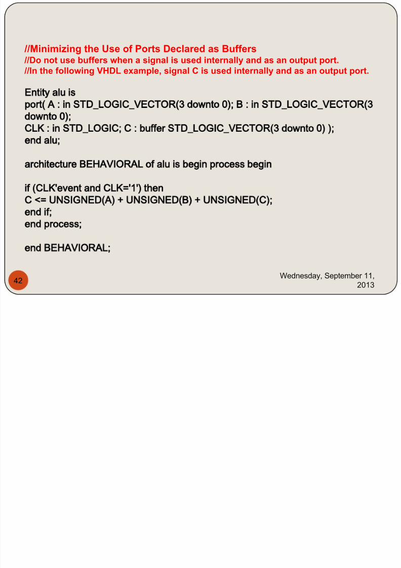
//Minimizing the Use of Ports Declared as Buffers //Do not use buffers when a signal is used internally and as an output port.
//In the following VHDL example, signal C is used internally and as an output port.
Entity alu is
port( A : in STD_LOGIC_VECTOR(3 downto 0); B : in STD_LOGIC_VECTOR(3
downto 0);
CLK : in STD_LOGIC; C : buffer STD_LOGIC_VECTOR(3 downto 0) );
end alu;
architecture BEHAVIORAL of alu is begin process begin
if (CLK'event and CLK='1') then
C <= UNSIGNED(A) + UNSIGNED(B) + UNSIGNED(C);
end if;end process;
end BEHAVIORAL;
7/29/2019 HDL PPT.ppsx
http://slidepdf.com/reader/full/hdl-pptppsx 43/91
Wednesday, September 11,
201343
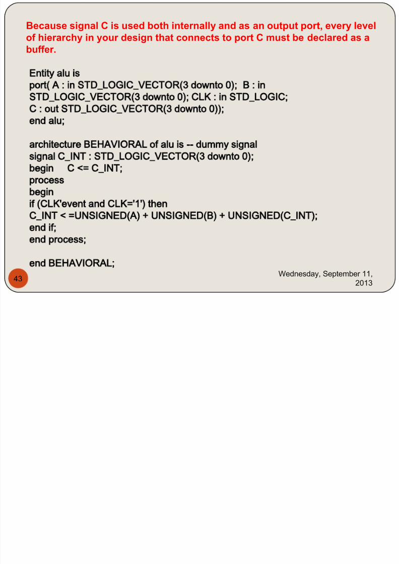
Because signal C is used both internally and as an output port, every levelof hierarchy in your design that connects to port C must be declared as abuffer.
Entity alu isport( A : in STD_LOGIC_VECTOR(3 downto 0); B : in
STD_LOGIC_VECTOR(3 downto 0); CLK : in STD_LOGIC;
C : out STD_LOGIC_VECTOR(3 downto 0));
end alu;
architecture BEHAVIORAL of alu is -- dummy signalsignal C_INT : STD_LOGIC_VECTOR(3 downto 0);
begin C <= C_INT;
process
begin
if (CLK'event and CLK='1') then
C_INT < =UNSIGNED(A) + UNSIGNED(B) + UNSIGNED(C_INT);
end if;
end process;
end BEHAVIORAL;
7/29/2019 HDL PPT.ppsx
http://slidepdf.com/reader/full/hdl-pptppsx 44/91
Wednesday, September 11,
201344
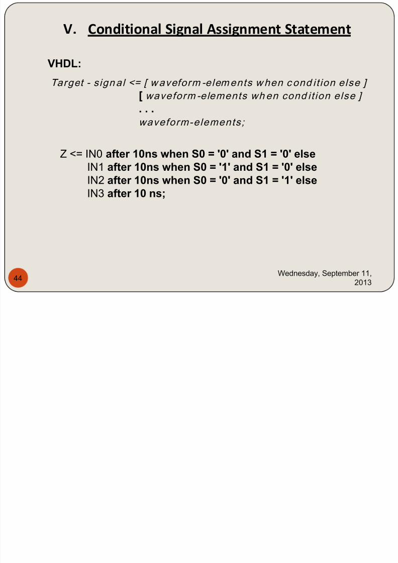
V. Conditional Signal Assignment Statement
VHDL:
Target - signal <= [ waveform -elements when cond it ion else ]
[ waveform -elements when cond it ion else ]
. . .waveform-elements;
Z <= IN0 after 10ns when S0 = '0' and S1 = '0' elseIN1 after 10ns when S0 = '1' and S1 = '0' elseIN2 after 10ns when S0 = '0' and S1 = '1' elseIN3 after 10 ns;
7/29/2019 HDL PPT.ppsx
http://slidepdf.com/reader/full/hdl-pptppsx 45/91
Wednesday, September 11,
201345
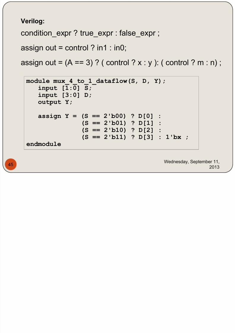
Verilog:
condition_expr ? true_expr : false_expr ;
assign out = control ? in1 : in0;
assign out = (A == 3) ? ( control ? x : y ): ( control ? m : n) ;
module mux_4_to_1_dataflow(S, D, Y);input [1:0] S;input [3:0] D;output Y;
assign Y = (S == 2'b00) ? D[0] :
(S == 2'b01) ? D[1] :(S == 2'b10) ? D[2] :(S == 2'b11) ? D[3] : 1'bx ;
endmodule
7/29/2019 HDL PPT.ppsx
http://slidepdf.com/reader/full/hdl-pptppsx 46/91
Wednesday, September 11,
201346
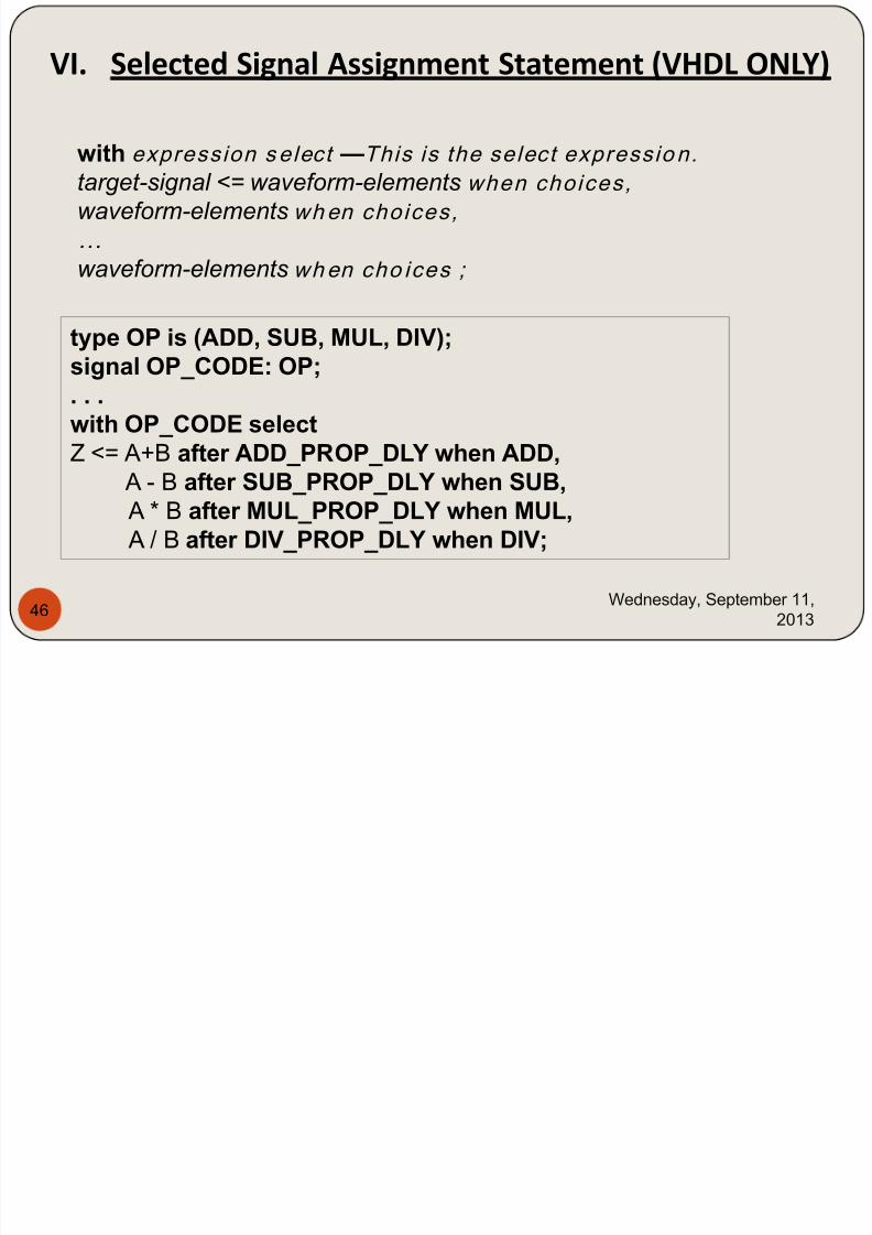
with expression select —This is the select expressio n.
target-signal <= waveform-elements when choices,
waveform-elements when choices,
…
waveform-elements when cho ices ;
VI. Selected Signal Assignment Statement (VHDL ONLY)
type OP is (ADD, SUB, MUL, DIV);signal OP_CODE: OP;. . .with OP_CODE select
Z <= A+B after ADD_PROP_DLY when ADD, A - B after SUB_PROP_DLY when SUB, A * B after MUL_PROP_DLY when MUL, A / B after DIV_PROP_DLY when DIV;
7/29/2019 HDL PPT.ppsx
http://slidepdf.com/reader/full/hdl-pptppsx 47/91
Wednesday, September 11,
201347
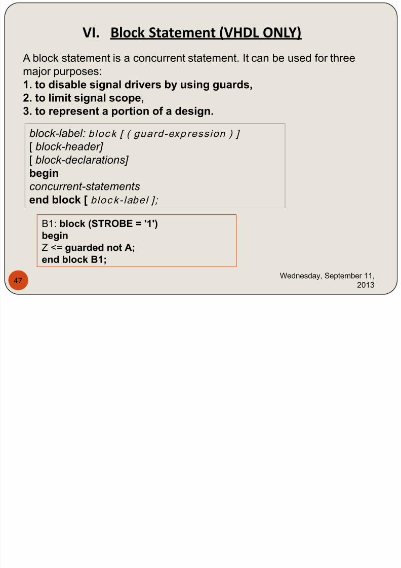
A block statement is a concurrent statement. It can be used for three
major purposes:1. to disable signal drivers by using guards,2. to limit signal scope,3. to represent a portion of a design.
VI. Block Statement (VHDL ONLY)
block-label: bloc k [ ( guard-exp ression ) ]
[ block-header] [ block-declarations]
beginconcurrent-statements
end block [ bloc k- label ];
B1: block (STROBE = '1')beginZ <= guarded not A;end block B1;
7/29/2019 HDL PPT.ppsx
http://slidepdf.com/reader/full/hdl-pptppsx 48/91
Wednesday, September 11,
201348
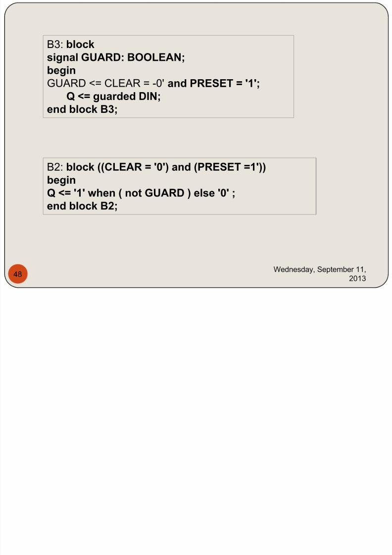
B3: blocksignal GUARD: BOOLEAN;
beginGUARD <= CLEAR = -0' and PRESET = '1';
Q <= guarded DIN;end block B3;
B2: block ((CLEAR = '0') and (PRESET =1'))beginQ <= '1' when ( not GUARD ) else '0' ;
end block B2;
7/29/2019 HDL PPT.ppsx
http://slidepdf.com/reader/full/hdl-pptppsx 49/91
Wednesday, September 11,
201349
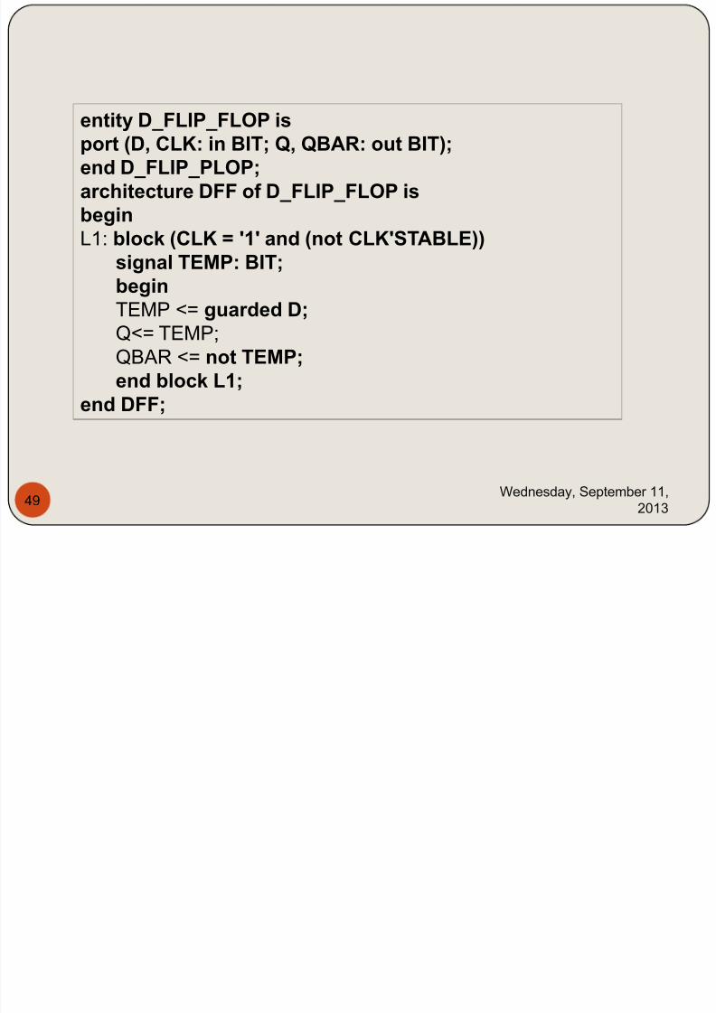
entity D_FLIP_FLOP isport (D, CLK: in BIT; Q, QBAR: out BIT);end D_FLIP_PLOP;architecture DFF of D_FLIP_FLOP isbeginL1: block (CLK = '1' and (not CLK'STABLE))
signal TEMP: BIT;beginTEMP <= guarded D;Q<= TEMP;
QBAR <= not TEMP;
end block L1;end DFF;
7/29/2019 HDL PPT.ppsx
http://slidepdf.com/reader/full/hdl-pptppsx 50/91
Wednesday, September 11,
201350
Some Examples:
X(1) X(0) Y(1) Y(0) X >Y X< Y X=Y

7/29/2019 HDL PPT.ppsx
http://slidepdf.com/reader/full/hdl-pptppsx 51/91
Wednesday, September 11,
201351
X(1) X(0) Y(1) Y(0) X >Y X< Y X Y
0 0 0 0 0 0 1
0 0 0 1 0 1 0
0 0 1 0 0 1 0
0 0 1 1 0 1 0
0 1 0 0 1 0 0
0 1 0 1 0 0 1
0 1 1 0 0 1 0
0 1 1 1 0 1 0
1 0 0 0 1 0 0
1 0 0 1 1 0 0
1 0 1 0 0 0 1
1 0 1 1 0 1 0
1 1 0 0 1 0 0
1 1 0 1 1 0 0
1 1 1 0 1 0 0
1 1 1 1 0 0 1
7/29/2019 HDL PPT.ppsx
http://slidepdf.com/reader/full/hdl-pptppsx 52/91
Wednesday, September 11,
201352
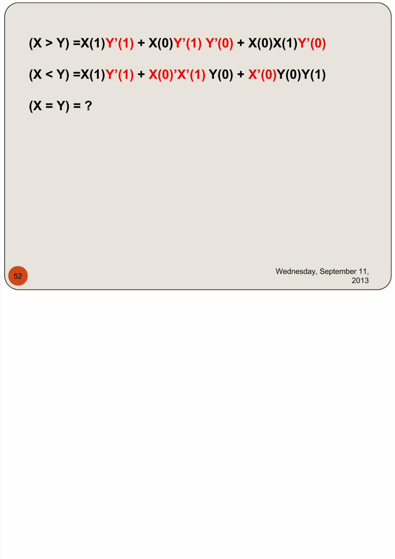
(X > Y) =X(1) Y’(1) + X(0) Y’(1) Y’(0) + X(0)X(1) Y’(0)
(X < Y) =X(1) Y’(1) + X(0)’X’(1) Y(0) + X’(0) Y(0)Y(1)
(X = Y) = ?
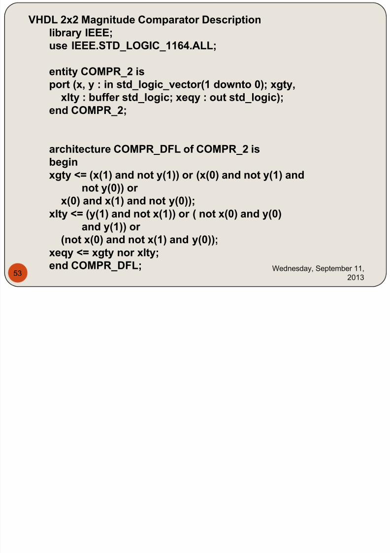
VHDL 2x2 Magnitude Comparator Description
7/29/2019 HDL PPT.ppsx
http://slidepdf.com/reader/full/hdl-pptppsx 53/91
Wednesday, September 11,
201353
VHDL 2x2 Magnitude Comparator Descriptionlibrary IEEE;use IEEE.STD_LOGIC_1164.ALL;
entity COMPR_2 isport (x, y : in std_logic_vector(1 downto 0); xgty,
xlty : buffer std_logic; xeqy : out std_logic);end COMPR_2;
architecture COMPR_DFL of COMPR_2 isbeginxgty <= (x(1) and not y(1)) or (x(0) and not y(1) and
not y(0)) or x(0) and x(1) and not y(0));
xlty <= (y(1) and not x(1)) or ( not x(0) and y(0)and y(1)) or
(not x(0) and not x(1) and y(0));xeqy <= xgty nor xlty;end COMPR_DFL;
7/29/2019 HDL PPT.ppsx
http://slidepdf.com/reader/full/hdl-pptppsx 54/91
Wednesday, September 11,
201354
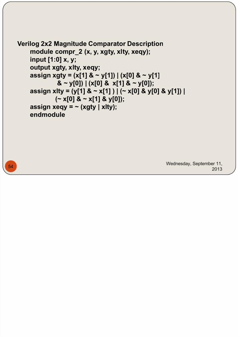
Verilog 2x2 Magnitude Comparator Descriptionmodule compr_2 (x, y, xgty, xlty, xeqy);input [1:0] x, y;output xgty, xlty, xeqy;assign xgty = (x[1] & ~ y[1]) | (x[0] & ~ y[1]
& ~ y[0]) | (x[0] & x[1] & ~ y[0]);assign xlty = (y[1] & ~ x[1] ) | (~ x[0] & y[0] & y[1]) |(~ x[0] & ~ x[1] & y[0]);
assign xeqy = ~ (xgty | xlty);endmodule
7/29/2019 HDL PPT.ppsx
http://slidepdf.com/reader/full/hdl-pptppsx 55/91
Wednesday, September 11,
201355
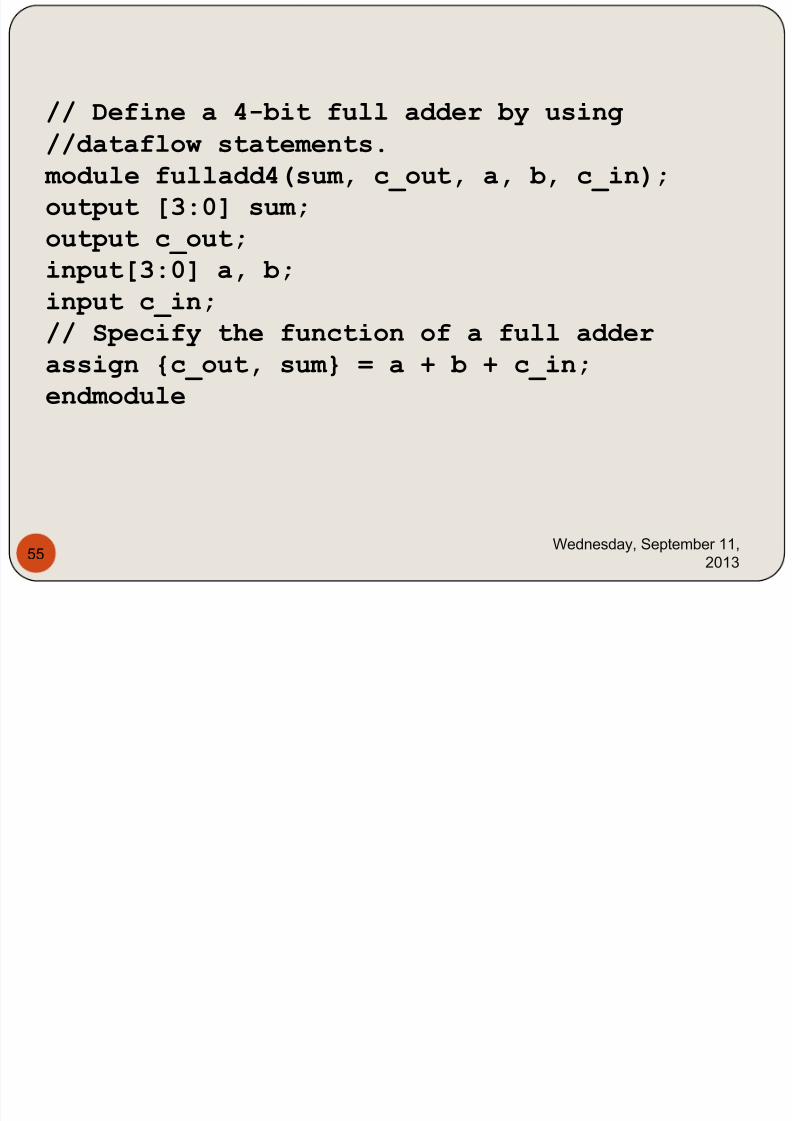
// Define a 4-bit full adder by using
//dataflow statements. module fulladd4(sum, c_out, a, b, c_in); output [3:0] sum; output c_out;
input[3:0] a, b;
input c_in; // Specify the function of a full adder assign {c_out, sum} = a + b + c_in; endmodule
7/29/2019 HDL PPT.ppsx
http://slidepdf.com/reader/full/hdl-pptppsx 56/91
Wednesday, September 11,
201356
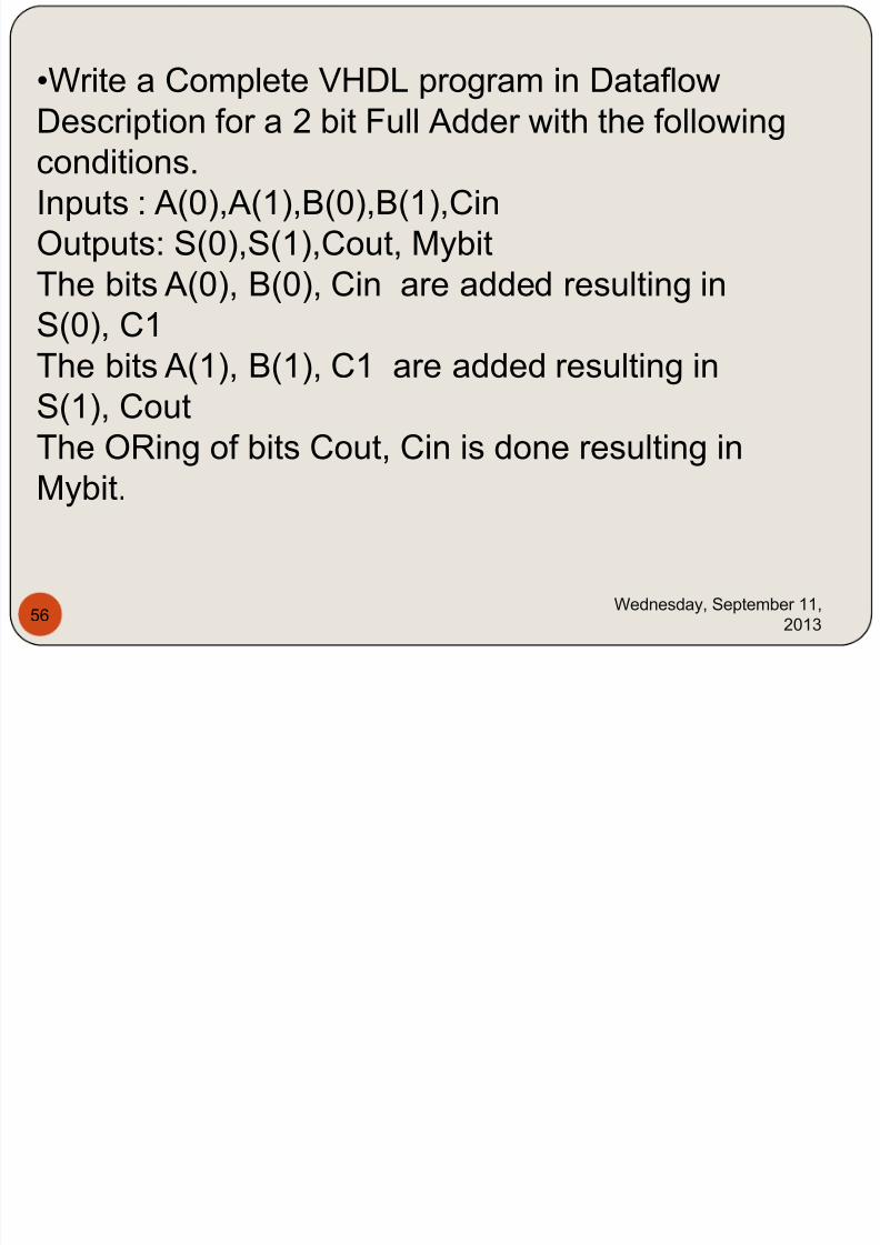
•Write a Complete VHDL program in Dataflow
Description for a 2 bit Full Adder with the following
conditions.Inputs : A(0),A(1),B(0),B(1),Cin
Outputs: S(0),S(1),Cout, Mybit
The bits A(0), B(0), Cin are added resulting in
S(0), C1The bits A(1), B(1), C1 are added resulting in
S(1), Cout
The ORing of bits Cout, Cin is done resulting in
Mybit.

7/29/2019 HDL PPT.ppsx
http://slidepdf.com/reader/full/hdl-pptppsx 57/91
Wednesday, September 11,
201357
7/29/2019 HDL PPT.ppsx
http://slidepdf.com/reader/full/hdl-pptppsx 58/91
Wednesday, September 11,
201358
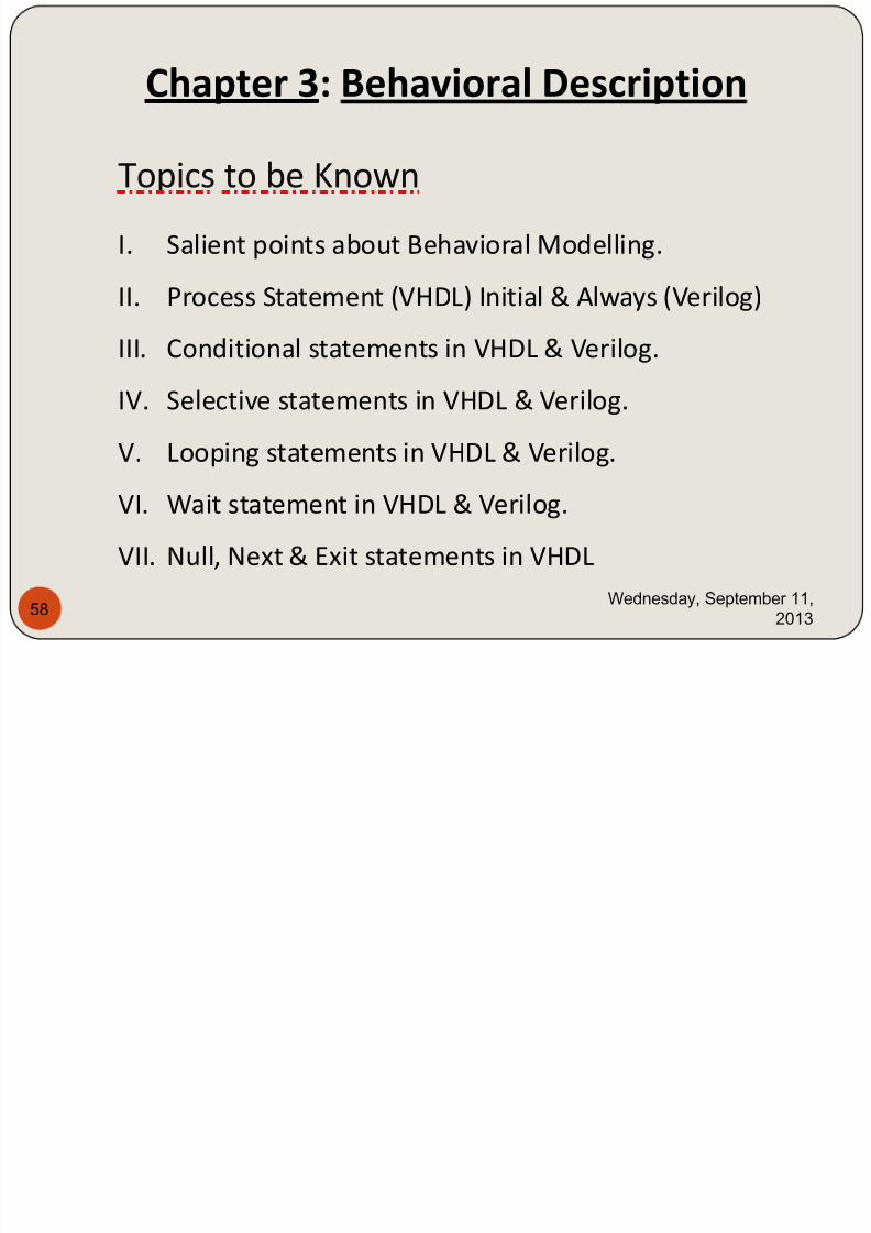
Chapter 3: Behavioral Description
Topics to be Known
I. Salient points about Behavioral Modelling.
II. Process Statement (VHDL) Initial & Always (Verilog)
III. Conditional statements in VHDL & Verilog.
IV. Selective statements in VHDL & Verilog.
V. Looping statements in VHDL & Verilog.VI. Wait statement in VHDL & Verilog.
VII. Null, Next & Exit statements in VHDL
7/29/2019 HDL PPT.ppsx
http://slidepdf.com/reader/full/hdl-pptppsx 59/91
Wednesday, September 11,
201359
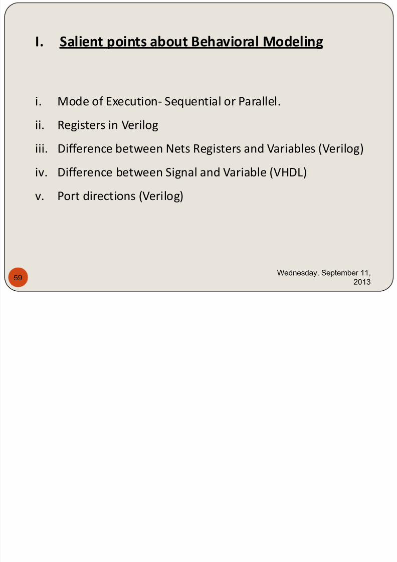
I. Salient points about Behavioral Modeling
i. Mode of Execution- Sequential or Parallel.
ii. Registers in Verilog
iii. Difference between Nets Registers and Variables (Verilog)
iv. Difference between Signal and Variable (VHDL)
v. Port directions (Verilog)
7/29/2019 HDL PPT.ppsx
http://slidepdf.com/reader/full/hdl-pptppsx 60/91
Wednesday, September 11,
201360
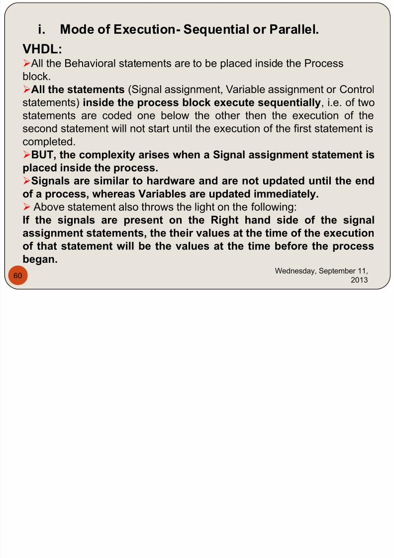
i. Mode of Execution- Sequential or Parallel.
VHDL: All the Behavioral statements are to be placed inside the Process
block.All the statements (Signal assignment, Variable assignment or Control
statements) inside the process block execute sequentially, i.e. of two
statements are coded one below the other then the execution of the
second statement will not start until the execution of the first statement is
completed.BUT, the complexity arises when a Signal assignment statement isplaced inside the process.Signals are similar to hardware and are not updated until the endof a process, whereas Variables are updated immediately.
Above statement also throws the light on the following:If the signals are present on the Right hand side of the signalassignment statements, the their values at the time of the executionof that statement will be the values at the time before the processbegan.
7/29/2019 HDL PPT.ppsx
http://slidepdf.com/reader/full/hdl-pptppsx 61/91
Wednesday, September 11,
201361
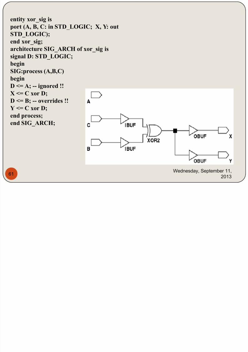
entity xor_sig is
port (A, B, C: in STD_LOGIC; X, Y: out
STD_LOGIC);
end xor_sig;
architecture SIG_ARCH of xor_sig is
signal D: STD_LOGIC;
begin
SIG:process (A,B,C)
begin
D <= A; -- ignored !!
X <= C xor D;
D <= B; -- overrides !!
Y <= C xor D;
end process;
end SIG_ARCH;
7/29/2019 HDL PPT.ppsx
http://slidepdf.com/reader/full/hdl-pptppsx 62/91
Wednesday, September 11,
201362
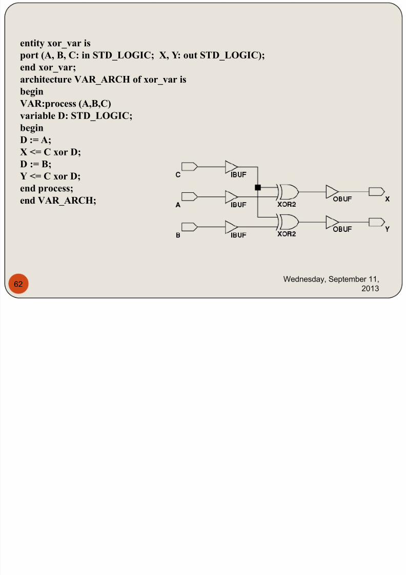
entity xor_var is
port (A, B, C: in STD_LOGIC; X, Y: out STD_LOGIC);
end xor_var;
architecture VAR_ARCH of xor_var is
begin
VAR:process (A,B,C)
variable D: STD_LOGIC;
begin
D := A;
X <= C xor D;
D := B;
Y <= C xor D;
end process;
end VAR_ARCH;
7/29/2019 HDL PPT.ppsx
http://slidepdf.com/reader/full/hdl-pptppsx 63/91
Wednesday, September 11,
201363
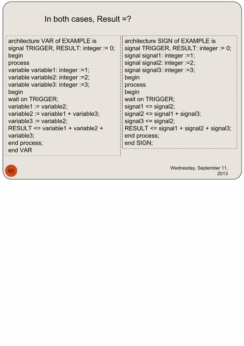
architecture VAR of EXAMPLE is
signal TRIGGER, RESULT: integer := 0;
begin
process
variable variable1: integer :=1;
variable variable2: integer :=2;
variable variable3: integer :=3;
begin
wait on TRIGGER;
variable1 := variable2;
variable2 := variable1 + variable3;
variable3 := variable2;
RESULT <= variable1 + variable2 +variable3;
end process;
end VAR
architecture SIGN of EXAMPLE is
signal TRIGGER, RESULT: integer := 0;
signal signal1: integer :=1;
signal signal2: integer :=2;
signal signal3: integer :=3;
begin
process
begin
wait on TRIGGER;
signal1 <= signal2;
signal2 <= signal1 + signal3;
signal3 <= signal2;
RESULT <= signal1 + signal2 + signal3;end process;
end SIGN;
In both cases, Result =?
7/29/2019 HDL PPT.ppsx
http://slidepdf.com/reader/full/hdl-pptppsx 64/91
Wednesday, September 11,
201364
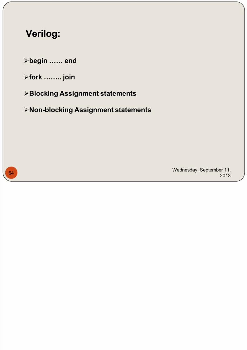
Verilog:
begin …… end
fork …….. join
Blocking Assignment statements
Non-blocking Assignment statements
7/29/2019 HDL PPT.ppsx
http://slidepdf.com/reader/full/hdl-pptppsx 65/91
Wednesday, September 11,
201365
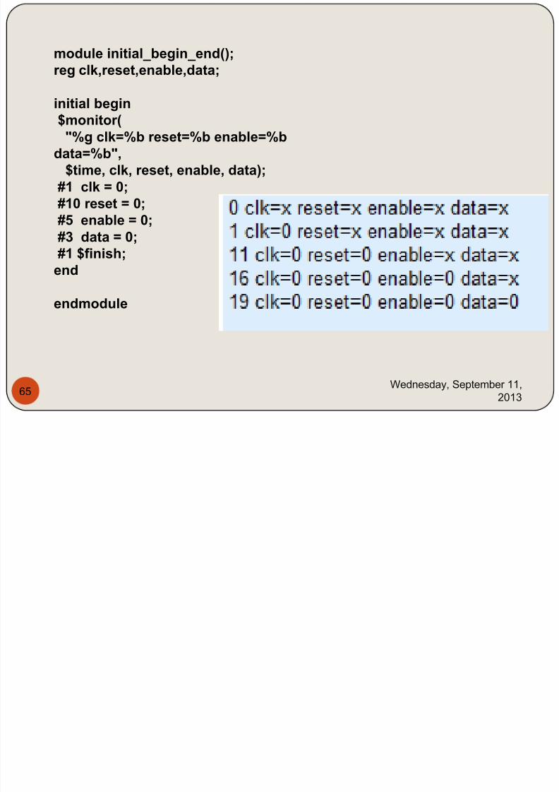
module initial_begin_end();reg clk,reset,enable,data;
initial begin$monitor("%g clk=%b reset=%b enable=%b
data=%b",$time, clk, reset, enable, data);
#1 clk = 0;
#10 reset = 0;#5 enable = 0;#3 data = 0;#1 $finish;
end
endmodule
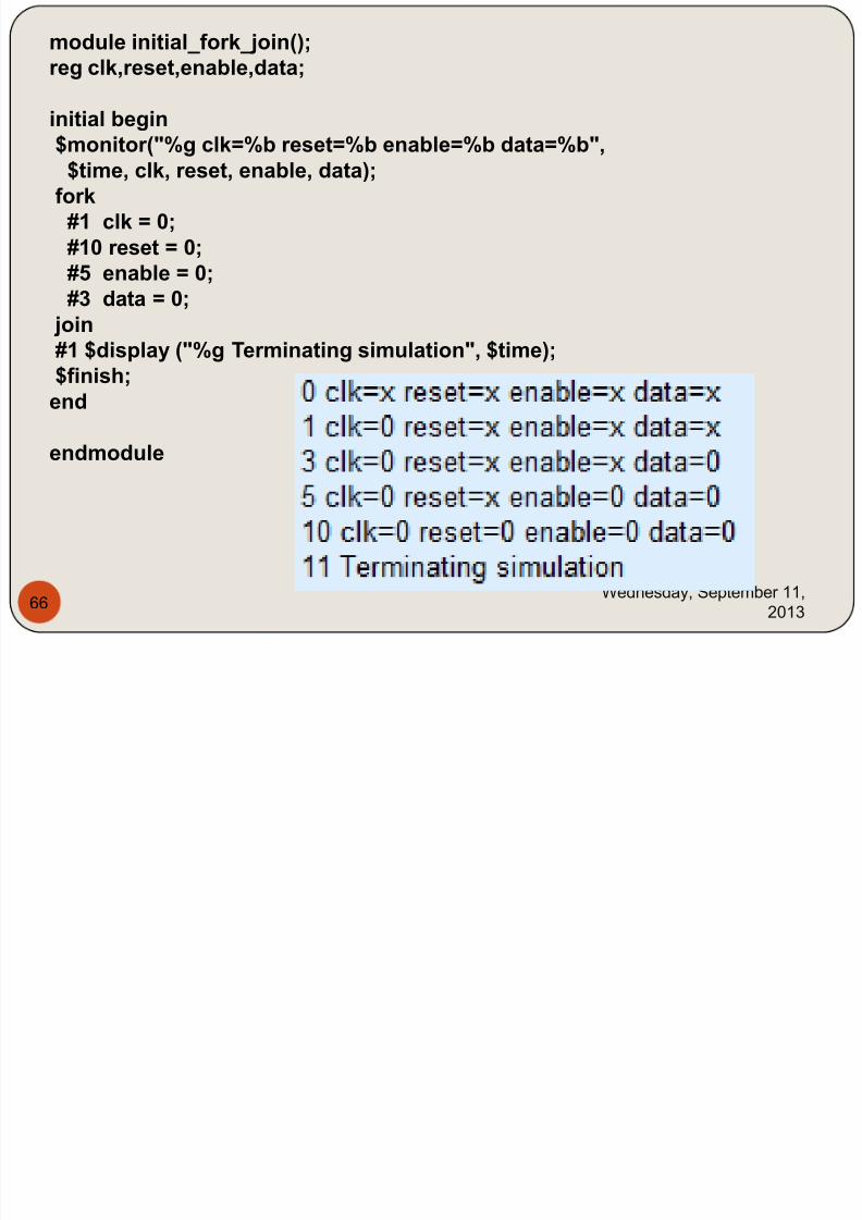
module initial fork join();
7/29/2019 HDL PPT.ppsx
http://slidepdf.com/reader/full/hdl-pptppsx 66/91
Wednesday, September 11,
201366
_ _j ();reg clk,reset,enable,data;
initial begin$monitor("%g clk=%b reset=%b enable=%b data=%b",
$time, clk, reset, enable, data);fork
#1 clk = 0;#10 reset = 0;#5 enable = 0;#3 data = 0;
join#1 $display ("%g Terminating simulation", $time);$finish;end
endmodule
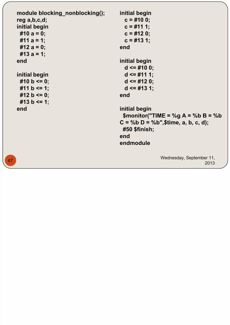
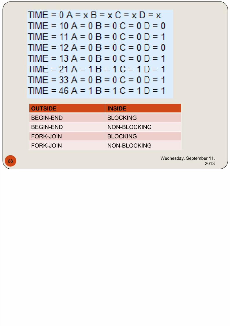
module blocking nonblocking(); initial begin
7/29/2019 HDL PPT.ppsx
http://slidepdf.com/reader/full/hdl-pptppsx 67/91
Wednesday, September 11,
201367
module blocking_nonblocking();reg a,b,c,d;initial begin#10 a = 0;
#11 a = 1;#12 a = 0;#13 a = 1;
end
initial begin
#10 b <= 0;#11 b <= 1;#12 b <= 0;#13 b <= 1;
end
initial beginc = #10 0;c = #11 1;c = #12 0;
c = #13 1;end
initial begind <= #10 0;d <= #11 1;
d <= #12 0;d <= #13 1;end
initial begin$monitor("TIME = %g A = %b B = %b
C = %b D = %b",$time, a, b, c, d);#50 $finish;
endendmodule
7/29/2019 HDL PPT.ppsx
http://slidepdf.com/reader/full/hdl-pptppsx 68/91
Wednesday, September 11,
201368
OUTSIDE INSIDE
BEGIN-END BLOCKING
BEGIN-END NON-BLOCKING
FORK-JOIN BLOCKING
FORK-JOIN NON-BLOCKING
7/29/2019 HDL PPT.ppsx
http://slidepdf.com/reader/full/hdl-pptppsx 69/91
Wednesday, September 11,
201369
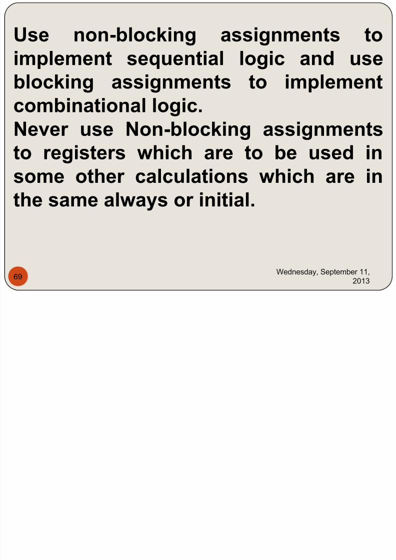
Use non-blocking assignments toimplement sequential logic and use
blocking assignments to implementcombinational logic.Never use Non-blocking assignmentsto registers which are to be used insome other calculations which are inthe same always or initial.
7/29/2019 HDL PPT.ppsx
http://slidepdf.com/reader/full/hdl-pptppsx 70/91
Wednesday, September 11,
201370
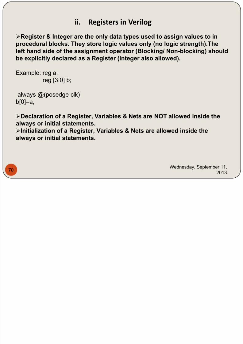
ii. Registers in Verilog
Register & Integer are the only data types used to assign values to in
procedural blocks. They store logic values only (no logic strength).Theleft hand side of the assignment operator (Blocking/ Non-blocking) shouldbe explicitly declared as a Register (Integer also allowed).
Example: reg a;
reg [3:0] b;
always @(posedge clk)
b[0]=a;
Declaration of a Register, Variables & Nets are NOT allowed inside thealways or initial statements.
Initialization of a Register, Variables & Nets are allowed inside thealways or initial statements.
7/29/2019 HDL PPT.ppsx
http://slidepdf.com/reader/full/hdl-pptppsx 71/91
Wednesday, September 11,
201371
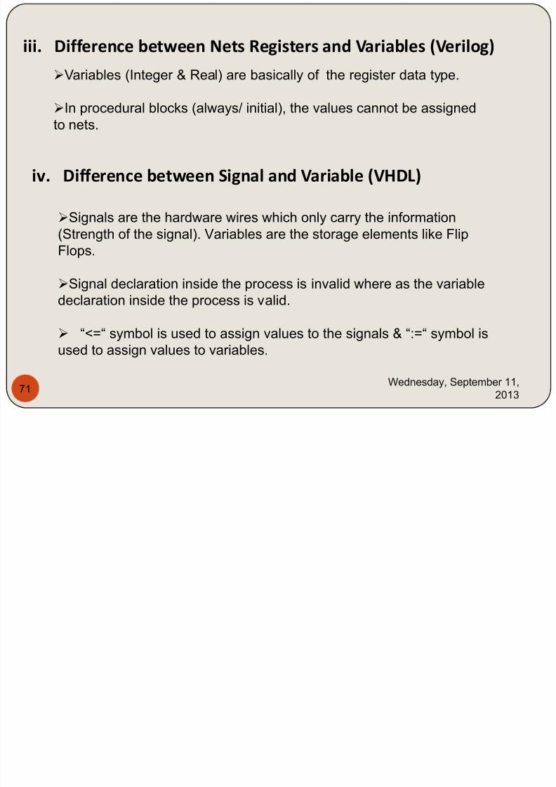
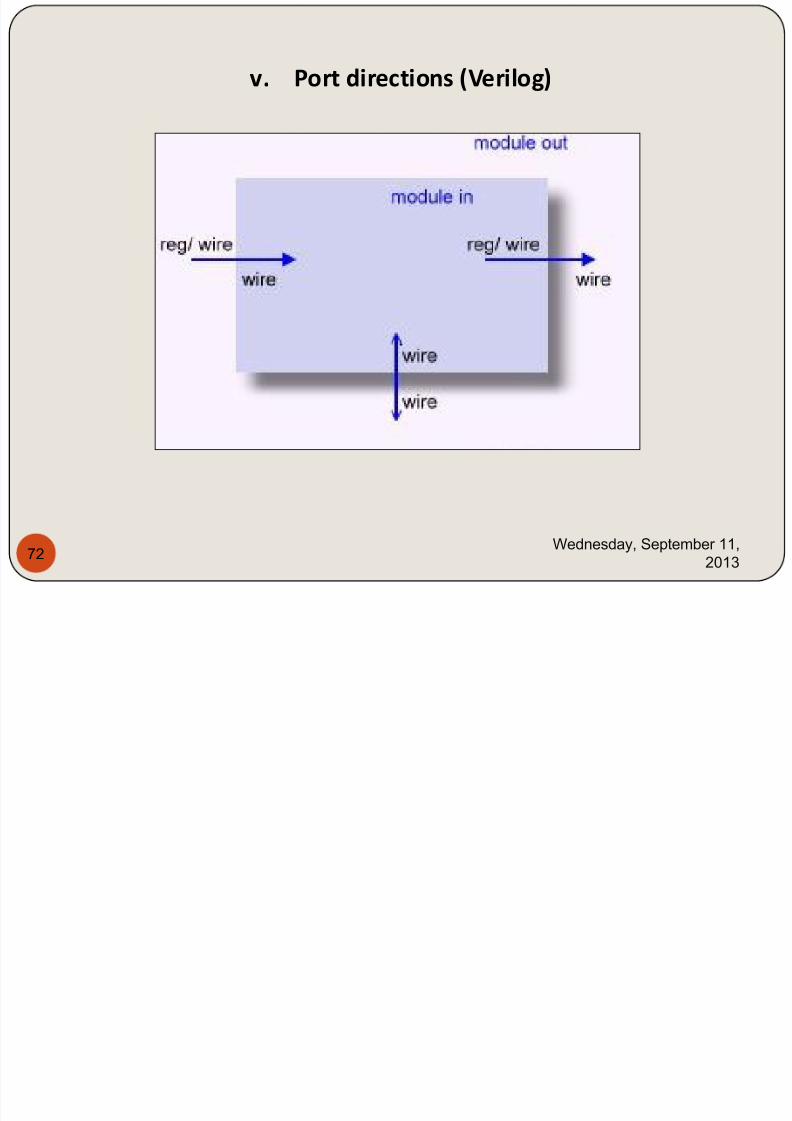
iii. Difference between Nets Registers and Variables (Verilog)
Variables (Integer & Real) are basically of the register data type.
In procedural blocks (always/ initial), the values cannot be assignedto nets.
Signals are the hardware wires which only carry the information
(Strength of the signal). Variables are the storage elements like Flip
Flops.
Signal declaration inside the process is invalid where as the variable
declaration inside the process is valid.
“<=“ symbol is used to assign values to the signals & “:=“ symbol is
used to assign values to variables.
iv. Difference between Signal and Variable (VHDL)
7/29/2019 HDL PPT.ppsx
http://slidepdf.com/reader/full/hdl-pptppsx 72/91
Wednesday, September 11,
201372
v. Port directions (Verilog)
II P St t t (VHDL) I iti l & Al (V il )
7/29/2019 HDL PPT.ppsx
http://slidepdf.com/reader/full/hdl-pptppsx 73/91
Wednesday, September 11,
201373
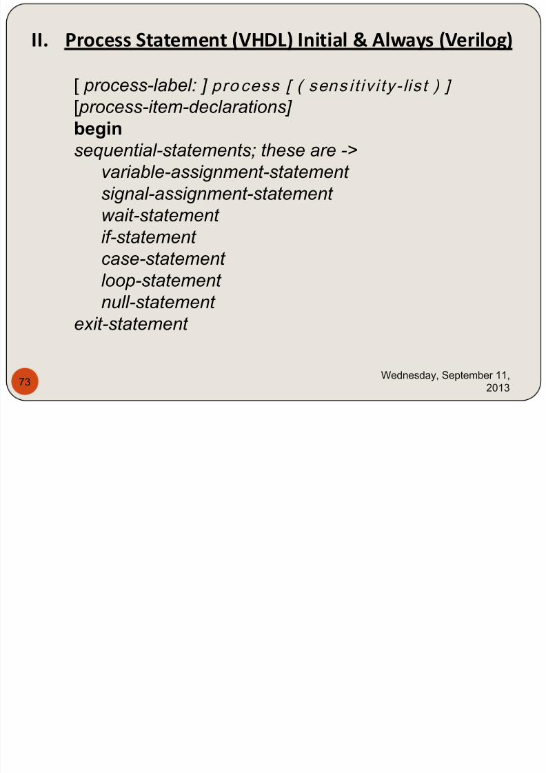
[ process-label: ] pro cess [ ( sens it iv i ty- lis t ) ]
[ process-item-declarations] beginsequential-statements; these are ->
variable-assignment-statement
signal-assignment-statement wait-statement
if-statement
case-statement
loop-statement
null-statement
exit-statement
II. Process Statement (VHDL) Initial & Always (Verilog)
7/29/2019 HDL PPT.ppsx
http://slidepdf.com/reader/full/hdl-pptppsx 74/91
Wednesday, September 11,
201374
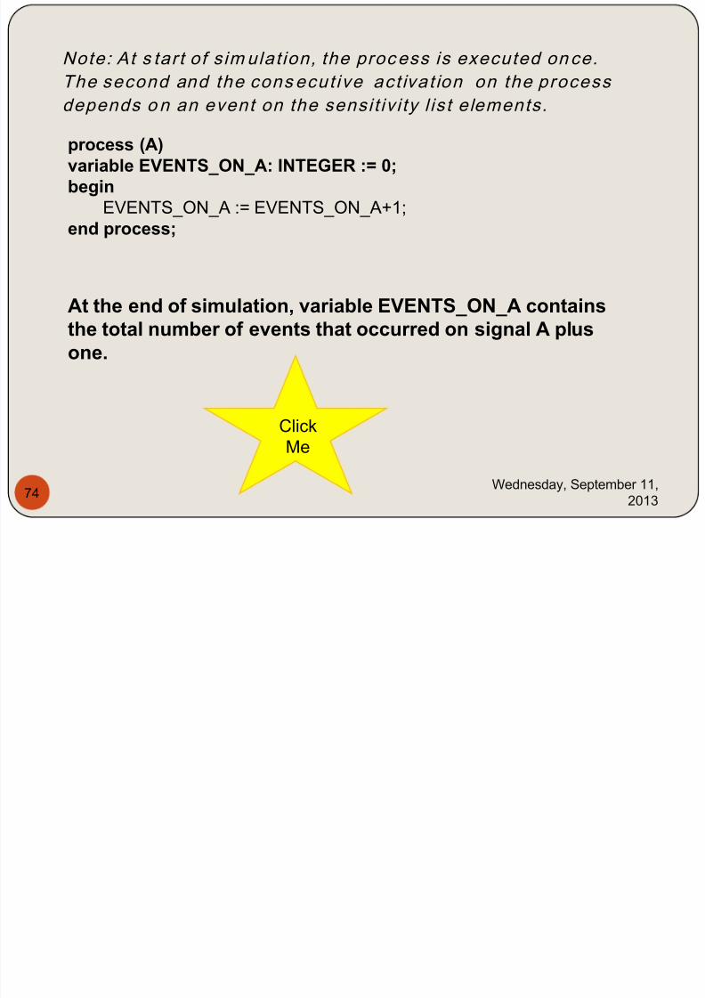
Note: At s tart of sim ulat ion, the process is executed once.
The second and the cons ecut ive act ivat ion on the process
depends on an event on the sensit iv i ty l ist elements.
process (A)variable EVENTS_ON_A: INTEGER := 0;begin
EVENTS_ON_A := EVENTS_ON_A+1;
end process;
At the end of simulation, variable EVENTS_ON_A containsthe total number of events that occurred on signal A plusone.
Click
Me

7/29/2019 HDL PPT.ppsx
http://slidepdf.com/reader/full/hdl-pptppsx 75/91
Wednesday, September 11,
201375
entity FULL_ADDER isport (A, B, Cin : in std_logic;
Sum, Cout : out std_logic);end FULL_ADDER;
architecture BEHAV_FA of FULL_ADDER issignal int1, int2, int3: std_logic;begin-- Process P1 that defines the first half adder P1: process (A, B)
begin
int1<= A xor B; int2<= A and B;
end process; -- Process P2 that defines the second half adder and the OR -- gate P2: process (int1, int2, Cin)
begin
Sum <= int1 xor Cin; int3 <= int1 and Cin; Cout <= int2 or int3;
end process; end BEHAV_FA;
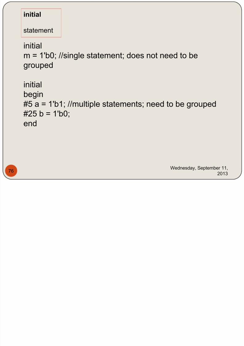
initial
7/29/2019 HDL PPT.ppsx
http://slidepdf.com/reader/full/hdl-pptppsx 76/91
Wednesday, September 11,
201376
statement
initialm = 1'b0; //single statement; does not need to be
grouped
initial
begin
#5 a = 1'b1; //multiple statements; need to be grouped
#25 b = 1'b0;
end
7/29/2019 HDL PPT.ppsx
http://slidepdf.com/reader/full/hdl-pptppsx 77/91
Wednesday, September 11,
201377
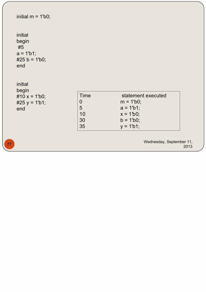
initial m = 1'b0;
initial
begin#5
a = 1'b1;
#25 b = 1'b0;
end
initial
begin
#10 x = 1'b0;
#25 y = 1'b1;
end
Time statement executed
0 m = 1'b0;
5 a = 1'b1;
10 x = 1'b0;
30 b = 1'b0;
35 y = 1'b1;
7/29/2019 HDL PPT.ppsx
http://slidepdf.com/reader/full/hdl-pptppsx 78/91
Wednesday, September 11,
201378
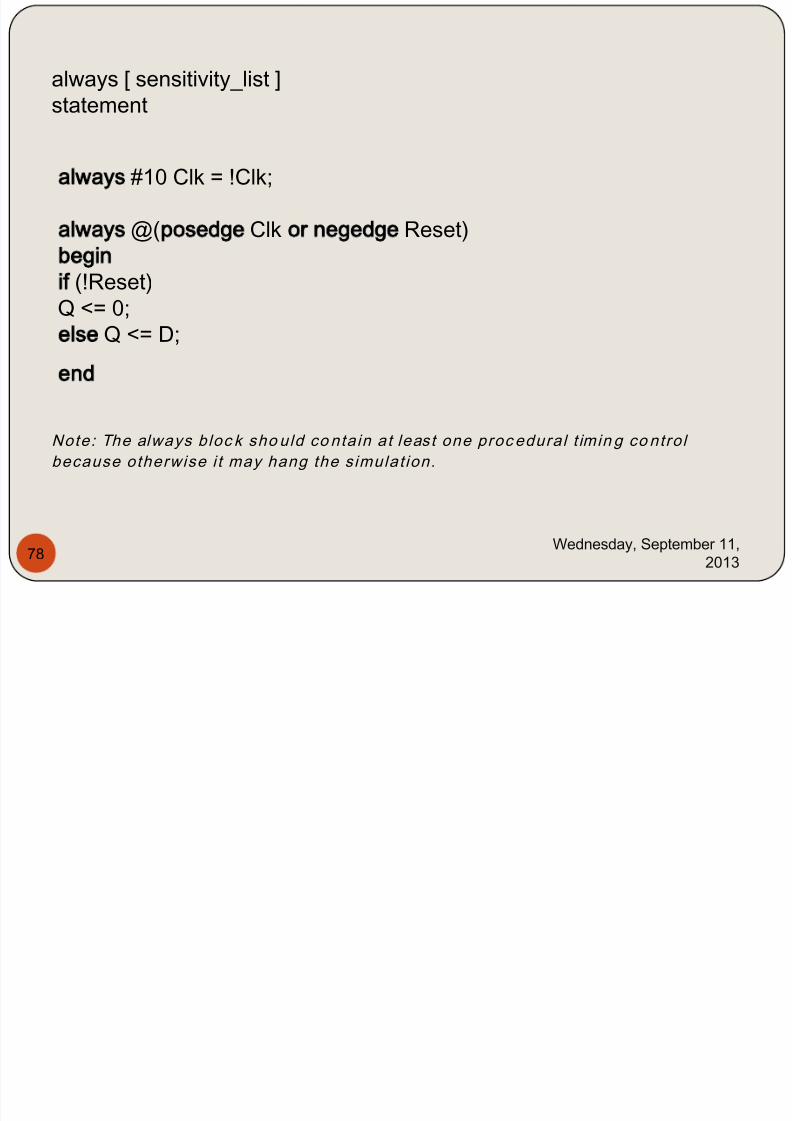
always [ sensitivity_list ]
statement
always #10 Clk = !Clk;
always @(posedge Clk or negedge Reset)begin
if (!Reset)Q <= 0;else Q <= D;
end
Note: The always bloc k sho uld co ntain at least one proc edural t imin g co ntro l
because otherwise i t may hang the simulat ion.
III Conditional statements in VHDL & Verilog
7/29/2019 HDL PPT.ppsx
http://slidepdf.com/reader/full/hdl-pptppsx 79/91
Wednesday, September 11,
201379
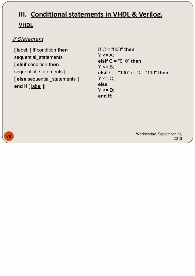
III. Conditional statements in VHDL & Verilog.
If Statement
VHDL
[ label: ] if condition then
sequential_statements
[ elsif condition then
sequential_statements ]
[ else sequential_statements ]
end if [ label ];
if C = "000" thenY <= A;
elsif C = "010" thenY <= B;
elsif C = "100" or C = "110" thenY <= C;
elseY <= D;
end if;
Verilog
7/29/2019 HDL PPT.ppsx
http://slidepdf.com/reader/full/hdl-pptppsx 80/91
Wednesday, September 11,
201380
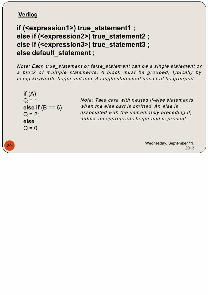
if (<expression1>) true_statement1 ;
else if (<expression2>) true_statement2 ;else if (<expression3>) true_statement3 ;else default_statement ;
Note: Each true_statement o r false_statement can b e a single statement o r
a block o f mul t ip le statements . A block mu st be grou ped, typical ly by
us ing keywords begin and end. A single statement need n ot be grou ped.
if (A)
Q = 1;
else if (B == 6)
Q = 2;else
Q = 0;
Note: Take care with n ested if-else statemen ts
wh en the else part is om it ted. An else is
associated with the immediately preceding if ,un less an app rop r iate begin -end is present.
Verilog
IV Selective statements in VHDL & Verilog
7/29/2019 HDL PPT.ppsx
http://slidepdf.com/reader/full/hdl-pptppsx 81/91
Wednesday, September 11,
201381
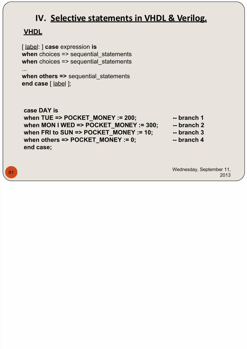
IV. Selective statements in VHDL & Verilog.
VHDL
[ label: ] case expression is when choices => sequential_statements
when choices => sequential_statements
...
when others => sequential_statements
end case [ label ];
case DAY iswhen TUE => POCKET_MONEY := 200; -- branch 1when MON I WED => POCKET_MONEY := 300; -- branch 2
when FRI to SUN => POCKET_MONEY := 10; -- branch 3when others => POCKET_MONEY := 0; -- branch 4end case;
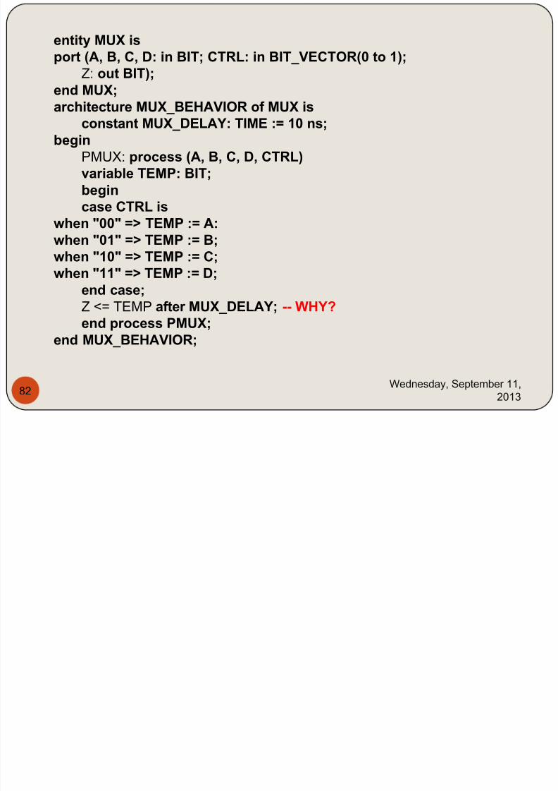
entity MUX is
7/29/2019 HDL PPT.ppsx
http://slidepdf.com/reader/full/hdl-pptppsx 82/91
Wednesday, September 11,
201382
entity MUX isport (A, B, C, D: in BIT; CTRL: in BIT_VECTOR(0 to 1);
Z: out BIT);end MUX;
architecture MUX_BEHAVIOR of MUX isconstant MUX_DELAY: TIME := 10 ns;
beginPMUX: process (A, B, C, D, CTRL)variable TEMP: BIT;begin
case CTRL iswhen "00" => TEMP := A:when "01" => TEMP := B;when "10" => TEMP := C;when "11" => TEMP := D;
end case;
Z <= TEMP after MUX_DELAY; -- WHY?end process PMUX;
end MUX_BEHAVIOR;
VerilogIf more than one statement is to
b t d f ti l t h
7/29/2019 HDL PPT.ppsx
http://slidepdf.com/reader/full/hdl-pptppsx 83/91
Wednesday, September 11,
2013
83
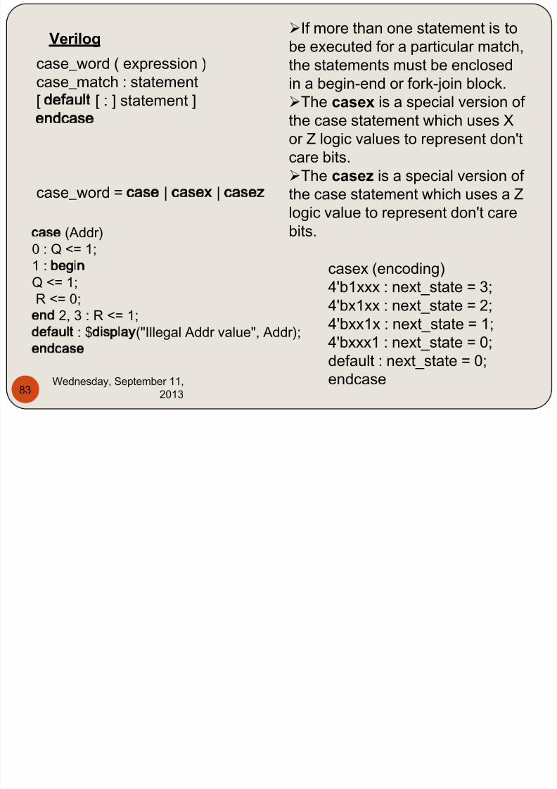
Verilog
case_word ( expression )case_match : statement
[ default [ : ] statement ]endcase
case_word = case | casex | casez
case (Addr)0 : Q <= 1;1 : begin Q <= 1;
R <= 0;end 2, 3 : R <= 1;default : $display("Illegal Addr value", Addr);endcase
casex (encoding)
4'b1xxx : next_state = 3;
4'bx1xx : next_state = 2;4'bxx1x : next_state = 1;
4'bxxx1 : next_state = 0;
default : next_state = 0;
endcase
be executed for a particular match,
the statements must be enclosed
in a begin-end or fork-join block.
The casex is a special version of the case statement which uses X
or Z logic values to represent don't
care bits.
The casez is a special version of
the case statement which uses a Z
logic value to represent don't care
bits.

7/29/2019 HDL PPT.ppsx
http://slidepdf.com/reader/full/hdl-pptppsx 84/91
Wednesday, September 11,
2013
84
module Encoder_4 (Int_req, Rout_addrs);input [3:0] Int_req;output [3:0] Rout_addrs;
reg [3:0] Rout_addrs;
always @ (Int_req)begin
casex (Int_req)4'bxxx1 : Rout_addrs=4'd1;4'bxx10 : Rout_addrs=4'd2;4'bx100 : Rout_addrs=4'd4;4'b1000 : Rout_addrs= 4'd8;default : Rout_addrs=4'd0;
endcase
endendmodule
V Looping Statements in VHDL and Verilog
7/29/2019 HDL PPT.ppsx
http://slidepdf.com/reader/full/hdl-pptppsx 85/91
Wednesday, September 11,
2013
85
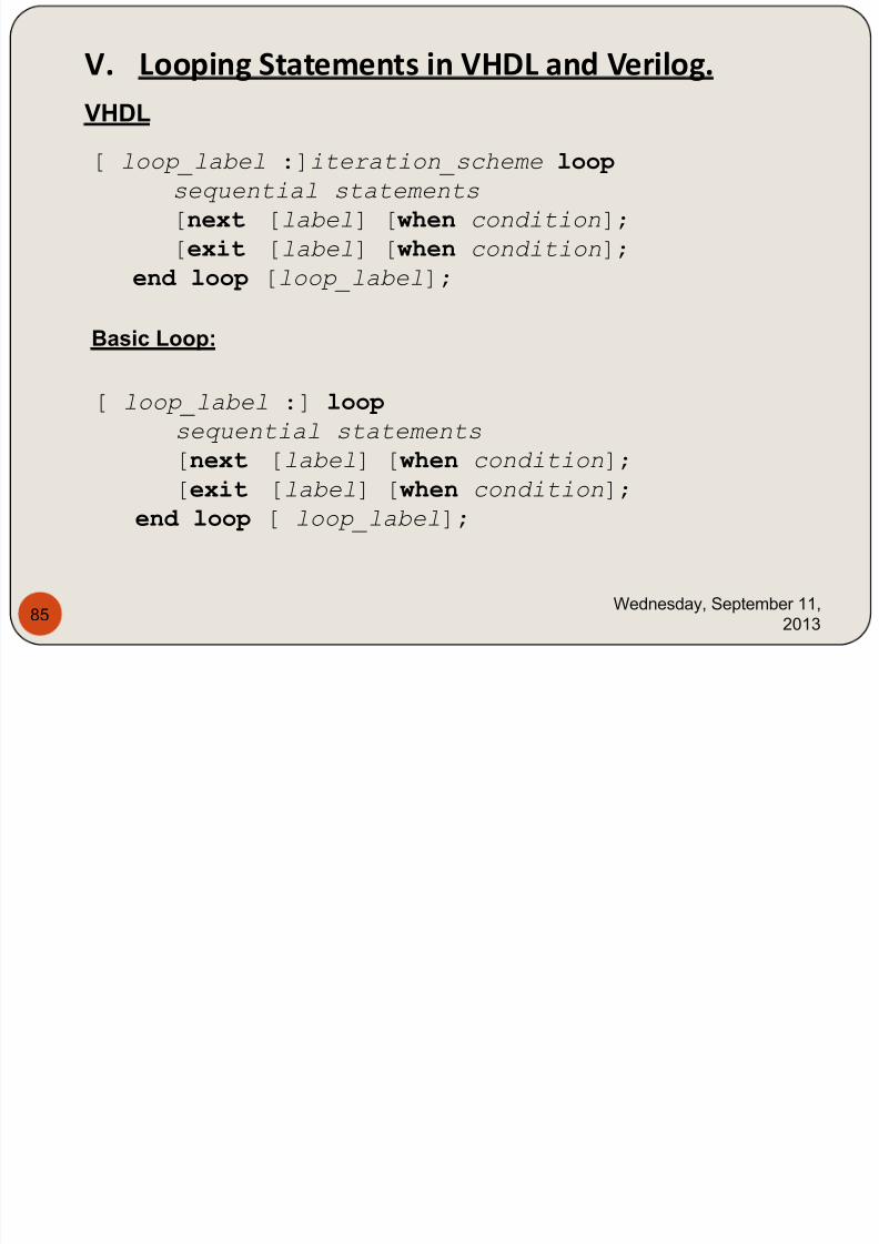
V. Looping Statements in VHDL and Verilog.
[ loop_label :]iteration_scheme loop sequential statements
[next [label] [ when condition];
[exit [label] [ when condition];
end loop [loop_label];
VHDL
Basic Loop:
[ loop_label :] loop
sequential statements
[next [label] [ when condition];
[exit [label] [ when condition];
end loop [ loop_label];
7/29/2019 HDL PPT.ppsx
http://slidepdf.com/reader/full/hdl-pptppsx 86/91
Wednesday, September 11,
2013
86
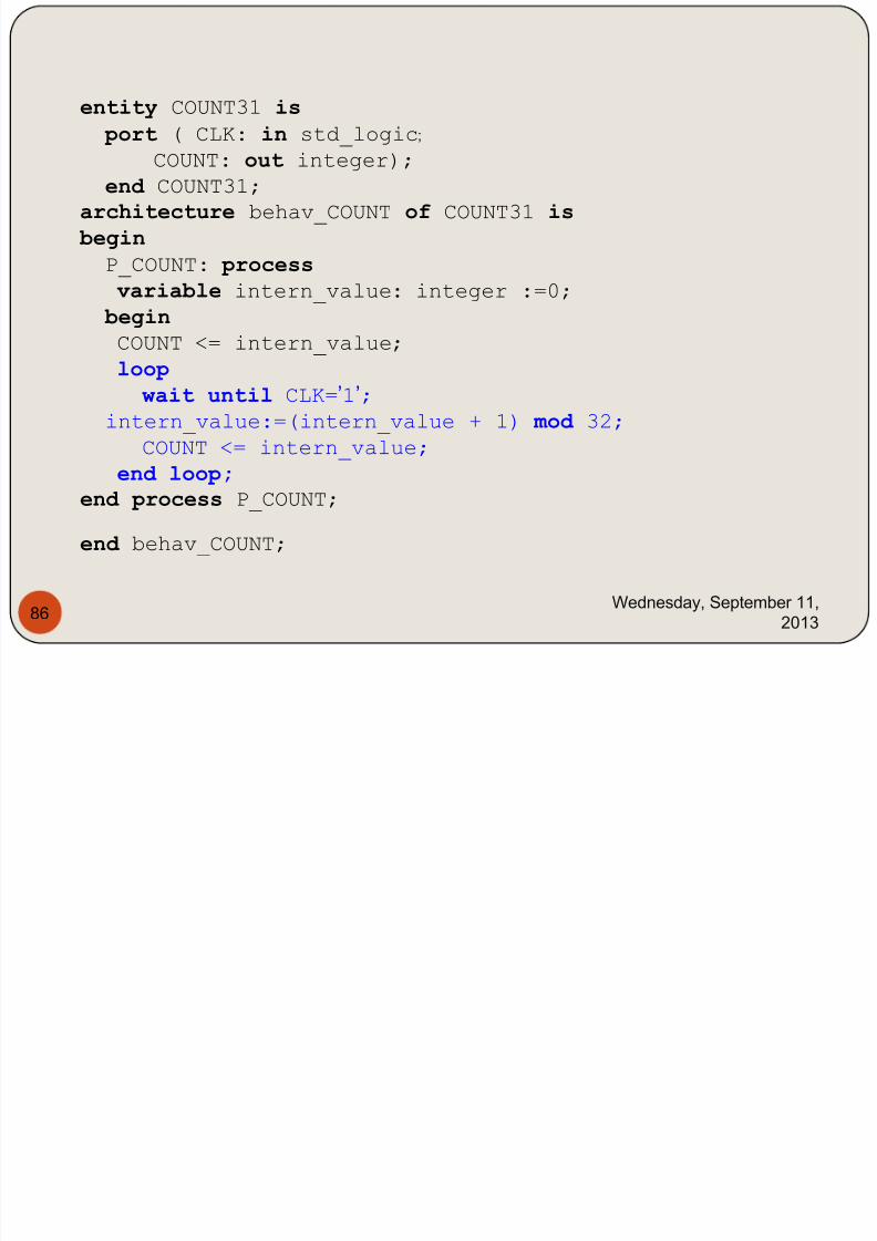
entity COUNT31 is
port ( CLK: in std_logic;
COUNT: out integer); end COUNT31;
architecture behav_COUNT of COUNT31 is
begin
P_COUNT: process
variable intern_value: integer :=0;
begin COUNT <= intern_value;
loop wait until CLK=’1’;
intern_value:=(intern_value + 1) mod 32;
COUNT <= intern_value;
end loop;
end process P_COUNT;
end behav_COUNT;
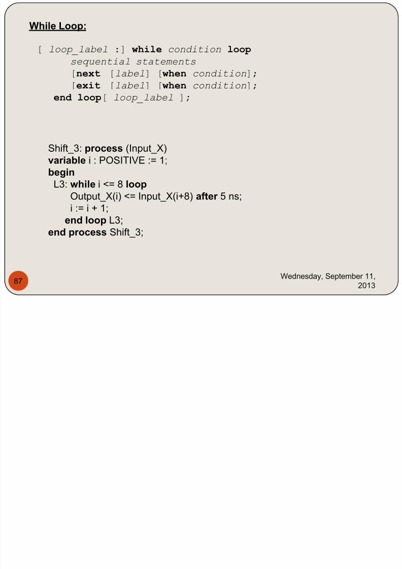
While Loop:
7/29/2019 HDL PPT.ppsx
http://slidepdf.com/reader/full/hdl-pptppsx 87/91
Wednesday, September 11,
2013
87
[ loop_label :] while condition loop
sequential statements
[next [label] [ when condition]; [exit [label] [ when condition];
end loop[ loop_label ];
Shift_3: process (Input_X)variable i : POSITIVE := 1;
begin
L3: while i <= 8 loop
Output_X(i) <= Input_X(i+8) after 5 ns;
i := i + 1;
end loop L3;end process Shift_3;
For Loop:

7/29/2019 HDL PPT.ppsx
http://slidepdf.com/reader/full/hdl-pptppsx 88/91
Wednesday, September 11,
2013
88
[ loop_label :] for identifier in range loop
sequential statements
[next [label] [ when condition];
[exit [label] [ when condition];
end loop[ loop_label ];
Shift_4: process (Input_X)
begin
L4: for count_value in 1 to 8 loop
Output_X(count_value) <=
Input_X(count_value + 8) after 5 ns;end loop L4;
end process Shift_4;

7/29/2019 HDL PPT.ppsx
http://slidepdf.com/reader/full/hdl-pptppsx 89/91
Wednesday, September 11,
2013
89
7/29/2019 HDL PPT.ppsx
http://slidepdf.com/reader/full/hdl-pptppsx 90/91
Wednesday, September 11,
2013
90
7/29/2019 HDL PPT.ppsx
http://slidepdf.com/reader/full/hdl-pptppsx 91/91