Embed Size (px)
DESCRIPTION
Trenchless technology
Citation preview
CALTRANS ENCROACHMENT PERMITS
GUIDELINES AND SPECIFICATIONS FOR
TRENCHLESS TECHNOLOGY PROJECTS
December 2014
2
TABLE OF CONTENTS PROCEDURAL REQUIREMENTS FOR DESIGN AND CALCULATIONS OF STRUCTURAL AND SUB-STRUCTURAL PROJECTS ........................................................................................................................................ 3 Structural Design and Calculations ............................................................................................................................. 3 Substructural Design and Calculations ....................................................................................................................... 3 Project Owner's Responsibilities .................................................................................................................................. 4 Contractor's Responsibilities ........................................................................................................................................ 4 TUNNELING PROJECTS ........................................................................................................................................... 5 Cal/Osha Requirements ................................................................................................................................................ 5 Tunnel ............................................................................................................................................................................. 6 Tunnel Shield ................................................................................................................................................................. 6 Tunnel Lining ................................................................................................................................................................. 6 Lagging ........................................................................................................................................................................... 6 Construction of Shafts and Pits .................................................................................................................................... 7 Placement of Shafts and Pits ......................................................................................................................................... 7 Excavation ...................................................................................................................................................................... 8 Dewatering ..................................................................................................................................................................... 8 Grouting ......................................................................................................................................................................... 8 Materials ......................................................................................................................................................................... 9 Project Owner's Responsibilities .................................................................................................................................. 9 Contractor's Responsibilities ........................................................................................................................................ 10 BORE & JACK .............................................................................................................................................................. 11 Bore and Receiving Pits ................................................................................................................................................ 11 Encasement Requirements ............................................................................................................................................ 11 HORIZONTAL DIRECTIONAL DRILLING ........................................................................................................... 13 Soil Investigations .......................................................................................................................................................... 13 Pre-construction & Site Evaluation ............................................................................................................................. 14 Installation Requirements ............................................................................................................................................. 14 Permittee/Contractor Responsibilities ......................................................................................................................... 15 Drilling Fluids Management Plan ................................................................................................................................ 16 Previous Experience ...................................................................................................................................................... 16 Safety ........................................................................................................................................................................... 16 Contingency Plans ......................................................................................................................................................... 17 Communications Plan ................................................................................................................................................... 17 Drilling Operations ........................................................................................................................................................ 17 Equipment Setup and Site Layout ............................................................................................................................... 17 Drilling and Back-Reaming .......................................................................................................................................... 17 Break-away Pulling Head ............................................................................................................................................. 17 Protective Coatings ........................................................................................................................................................ 18 Drilling Fluid - collection and disposal practices ........................................................................................................ 18 Site Restoration and Post Construction Evaluation ................................................................................................... 18 MICRO-TUNNELING ................................................................................................................................................. 19 Micro-tunneling Plan Set Submittal ............................................................................................................................ 19 Contractor's Submittal .................................................................................................................................................. 20 PIPE RAMMING .......................................................................................................................................................... 21 PIPE BURSTING .......................................................................................................................................................... 22
3
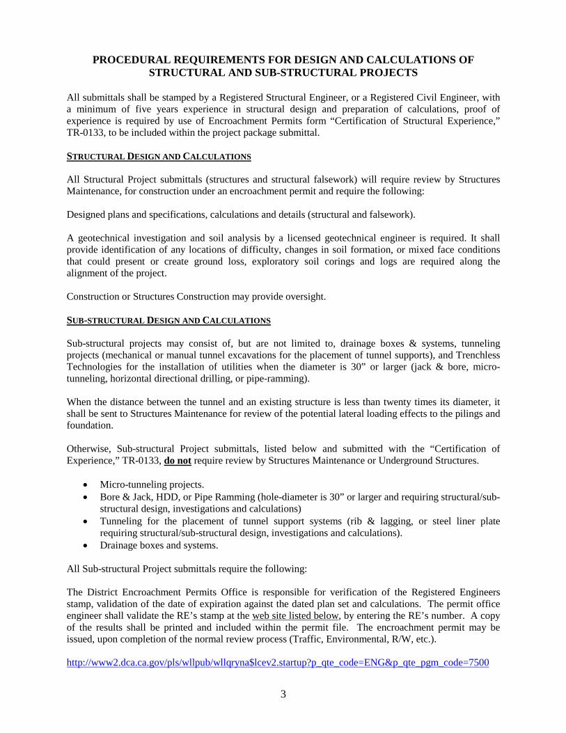
PROCEDURAL REQUIREMENTS FOR DESIGN AND CALCULATIONS OF STRUCTURAL AND SUB-STRUCTURAL PROJECTS
All submittals shall be stamped by a Registered Structural Engineer, or a Registered Civil Engineer, with a minimum of five years experience in structural design and preparation of calculations, proof of experience is required by use of Encroachment Permits form “Certification of Structural Experience,” TR-0133, to be included within the project package submittal. STRUCTURAL DESIGN AND CALCULATIONS All Structural Project submittals (structures and structural falsework) will require review by Structures Maintenance, for construction under an encroachment permit and require the following: Designed plans and specifications, calculations and details (structural and falsework). A geotechnical investigation and soil analysis by a licensed geotechnical engineer is required. It shall provide identification of any locations of difficulty, changes in soil formation, or mixed face conditions that could present or create ground loss, exploratory soil corings and logs are required along the alignment of the project. Construction or Structures Construction may provide oversight. SUB-STRUCTURAL DESIGN AND CALCULATIONS Sub-structural projects may consist of, but are not limited to, drainage boxes & systems, tunneling projects (mechanical or manual tunnel excavations for the placement of tunnel supports), and Trenchless Technologies for the installation of utilities when the diameter is 30” or larger (jack & bore, micro-tunneling, horizontal directional drilling, or pipe-ramming). When the distance between the tunnel and an existing structure is less than twenty times its diameter, it shall be sent to Structures Maintenance for review of the potential lateral loading effects to the pilings and foundation. Otherwise, Sub-structural Project submittals, listed below and submitted with the “Certification of Experience,” TR-0133, do not require review by Structures Maintenance or Underground Structures.
• Micro-tunneling projects. • Bore & Jack, HDD, or Pipe Ramming (hole-diameter is 30” or larger and requiring structural/sub-
structural design, investigations and calculations) • Tunneling for the placement of tunnel support systems (rib & lagging, or steel liner plate
requiring structural/sub-structural design, investigations and calculations). • Drainage boxes and systems.
All Sub-structural Project submittals require the following: The District Encroachment Permits Office is responsible for verification of the Registered Engineers stamp, validation of the date of expiration against the dated plan set and calculations. The permit office engineer shall validate the RE’s stamp at the web site listed below, by entering the RE’s number. A copy of the results shall be printed and included within the permit file. The encroachment permit may be issued, upon completion of the normal review process (Traffic, Environmental, R/W, etc.). http://www2.dca.ca.gov/pls/wllpub/wllqryna$lcev2.startup?p_qte_code=ENG&p_qte_pgm_code=7500
4
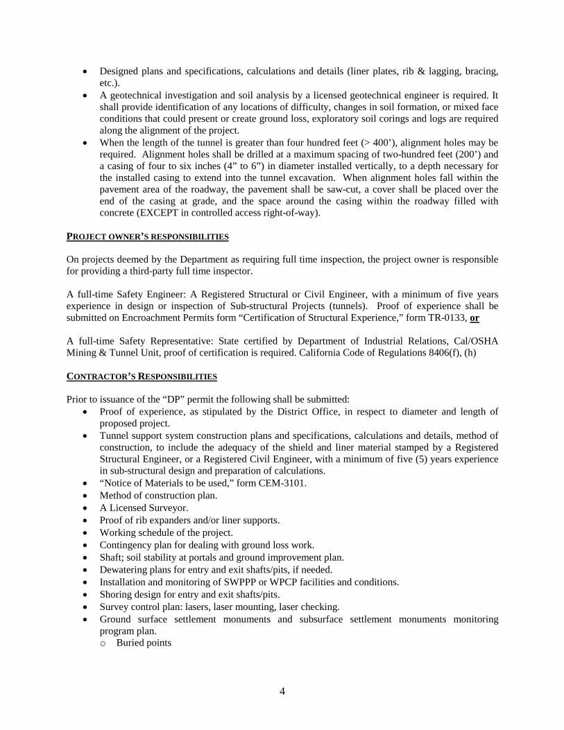
• Designed plans and specifications, calculations and details (liner plates, rib & lagging, bracing,
etc.). • A geotechnical investigation and soil analysis by a licensed geotechnical engineer is required. It
shall provide identification of any locations of difficulty, changes in soil formation, or mixed face conditions that could present or create ground loss, exploratory soil corings and logs are required along the alignment of the project.
• When the length of the tunnel is greater than four hundred feet (> 400’), alignment holes may be required. Alignment holes shall be drilled at a maximum spacing of two-hundred feet (200’) and a casing of four to six inches (4” to 6”) in diameter installed vertically, to a depth necessary for the installed casing to extend into the tunnel excavation. When alignment holes fall within the pavement area of the roadway, the pavement shall be saw-cut, a cover shall be placed over the end of the casing at grade, and the space around the casing within the roadway filled with concrete (EXCEPT in controlled access right-of-way).
PROJECT OWNER’S RESPONSIBILITIES On projects deemed by the Department as requiring full time inspection, the project owner is responsible for providing a third-party full time inspector. A full-time Safety Engineer: A Registered Structural or Civil Engineer, with a minimum of five years experience in design or inspection of Sub-structural Projects (tunnels). Proof of experience shall be submitted on Encroachment Permits form “Certification of Structural Experience,” form TR-0133, or A full-time Safety Representative: State certified by Department of Industrial Relations, Cal/OSHA Mining & Tunnel Unit, proof of certification is required. California Code of Regulations 8406(f), (h)
CONTRACTOR’S RESPONSIBILITIES Prior to issuance of the “DP” permit the following shall be submitted:
• Proof of experience, as stipulated by the District Office, in respect to diameter and length of proposed project.
• Tunnel support system construction plans and specifications, calculations and details, method of construction, to include the adequacy of the shield and liner material stamped by a Registered Structural Engineer, or a Registered Civil Engineer, with a minimum of five (5) years experience in sub-structural design and preparation of calculations.
• “Notice of Materials to be used,” form CEM-3101. • Method of construction plan. • A Licensed Surveyor. • Proof of rib expanders and/or liner supports. • Working schedule of the project. • Contingency plan for dealing with ground loss work. • Shaft; soil stability at portals and ground improvement plan. • Dewatering plans for entry and exit shafts/pits, if needed. • Installation and monitoring of SWPPP or WPCP facilities and conditions. • Shoring design for entry and exit shafts/pits. • Survey control plan: lasers, laser mounting, laser checking. • Ground surface settlement monuments and subsurface settlement monuments monitoring
program plan. o Buried points
5
TUNNELING PROJECTS All projects will vary in their own characteristics. General similarities are listed below to provide a general understanding of these types of projects. Establishment of a survey-grid line and existing elevation points shall be over the centerline and wing points of the installation. Designed plans and specifications, calculations and details (liner plates, rib & lagging, bracing, etc.) shall be stamped by a Registered Structural Engineer, or a Registered Civil Engineer, with a minimum of five (5) years experience in sub-structural design of tunnels. Proof of experience shall be submitted on “Certification of Structural Experience,” form TR-0133, in conjunction with project package submittal. A geotechnical investigation and soil analysis by a licensed geotechnical engineer/engineering geologist is required. It shall provide identification of any locations of difficulty, changes in soil formation, or mixed face conditions that could present or create ground loss, exploratory soil corings and logs are required along the tunnel alignment at intervals of twenty-five to one-hundred feet {25’ to 100’}. When the length of the tunnel is greater than four hundred feet (> 400’), alignment holes may be required. Alignment holes shall be drilled at a maximum spacing of two-hundred feet (200’) and a casing of four to six inches (4” to 6”) in diameter installed vertically, to a depth necessary for the installed casing to extend into the tunnel excavation. When alignment holes fall within the pavement area of the roadway, the pavement shall be saw-cut, a cover shall be placed over the end of the casing at grade, and the space around the casing within the roadway filled with concrete (EXCEPT in controlled access right-of-way). CAL/OSHA REQUIREMENTS The California Code of Regulations (CCR) mandates the following requirements for Tunneling Projects.
• The Owner or Local Entity proposing the construction of the tunnel shall make a full submittal to the Department of Industrial Relations, Cal/OSHA, to determine tunnel classification. CCR 8422
• Development of a check-in/check-out procedure to ensure an accurate account of personnel underground in the event of an emergency. CCR 8410
• Development of an Emergency Plan, that outlines duties and responsibilities of all personnel on the project during an emergency. The plan shall include ventilation controls, fire fighting equipment, rescue procedures, evacuation plans and communications. CCR 8426
• Cal/OSHA requires a State of California certified person performing the duties of gas tester or safety representative to be certified by passing a written and an oral examination administered by the Cal/OSHA Mining & Tunneling Unit. CCR 8406(f), (h)
• A certified safety representative shall direct the required safety and health program and must be on-site while employees are engaged in operations during which the Tunnel Safety Orders (TSO) apply. CCR 8406(f)
• The certified safety representative must have knowledge in underground safety, must be able to recognize hazards, and must have the authority to correct unsafe conditions and procedures subject to the TSO. CCR 8406(f)
A State of California certified gas tester is required for the following operations:
• All classifications other than non-gassy • Projects during which diesel equipment is used underground • Hazardous underground gas conditions. CCR 8470
6
TUNNEL Tunnel construction is accomplished by the method of Hand-mining, or by Mechanical means, and the use of a protective shield. Continuous monitoring and observation of the ground surface above the tunnel is required. In some cases it may be required to survey and record elevations along the survey grid line, several times a day, or daily. Generally, when tunneling in good ground, tunnels with a diameter of less than eight-feet (< 8’) and less than three-hundred feet to four-hundred feet (300’ to 400’) in length may be holed-through (excavated completely) before concreting the interior of the tunnel, when placement of pre-fabricated or pre-cast pipe is to be installed. When this is proposed, hole-through (unsupported length) before concreting of the interior of the tunnel, it shall be justified by the original subsurface geotechnical investigation and design. Tunnel lining and bracing should consist of steel ribs and steel spreaders (dutchmen) with wood, concrete, or steel lagging, or with bolted steel liner plates. Fireproof materials should be utilized in all construction of plant structures, above ground, within one hundred feet (100’) of the shaft or tunnel. The use of flammable materials or wood shoring would require that adequate fire protection be provided. Ventilation systems shall be established and provide a minimum of two hundred (200) cfm per worker.
• All equipment shall maintain a minimum clearance of twenty-five feet (25’) from opening. • An established contingency plan in the event of ground loss. • Cranes utilized in operations shall maintain minimum required clearances.
TUNNEL SHIELD
• The face of the shield shall be provided with a hood or an approved grid system. • The excavation face shall have a sufficient length to allow for the installation of one (1) complete
ring of liner plates, or one (1) complete set of ribs and lagging before advancing. • The contractor shall submit details and design information of the shield.
TUNNEL LINING Tunnel lining and bracing should consist of steel ribs and steel spreaders with wood lagging and concrete, or steel lagging, or with bolted steel liner plates. The tunnel liner and bracing shall be designed (calculations provided) of an adequate strength based upon the geotechnical investigation, soil analysis, loading, and the diameter and depth of cover to provide adequate support of the tunnel.
• A ring expander shall be used to expand the rib continuously outward and upward. • Liner plates shall be designed based on joint strength, minimum stiffness, critical buckling of the
liner plate wall, and deflection or flattening of the tunnel section. • On tunnels with a diameter greater than ten feet (> 10’), the placement of ribs inside of liner plate
may be required. • When the geotechnical investigation has determined that silts and fine sands exist, that may flow
under pressure, all liner plates shall include a neoprene gasket adhered to each flange face.
7
LAGGING
Generally started at spring line and continue upwards towards the crown. Lag spacing consists of three methods:
1. Wedging – done by driving a block of wood between the earth and the lag at each end, or by driving a wedge between the rib and the lag.
2. Stops – by welding small angles to the ribs outer flange to prevent sliding. 3. Clamps – which are applied to wood or steel lags.
If the spacing of lags between ribs is used in tunnel construction, packing between lags with filler may be required.
• Lags are boards or steel plates placed longitudinally against the roof and walls of the tunnel excavation.
• Steel lagging may consist of channel, liner plate or corrugated metal. • Steel lagging thickness shall be designed on strength based upon the geotechnical investigation,
soil analysis, and loading. • Wood lagging thickness shall be designed on strength based upon the geotechnical investigation,
soil analysis, loading. Generally wooden lags common size are three-inches by six-inches (3” x 6”), and the length is cut according to the spacing of the ribs.
• A minimum of one liner plate per ring with a two-inch (2”) diameter coupling for grouting is required.
THE CONSTRUCTION OF SHAFTS / PITS Shafts / pits should be constructed of a proper size and shape, and equipped as to allow work to be carried on safely.
• Shafts shall be constructed of driven steel sheet pilings, steel bracing and tight wood, or steel lagging or steel liner plates and ribs.
• The removal of spoils should be accomplished by mechanical means (muck box). • All shafts shall be provided with guardrail and a toeboard. • When ladders are utilized within the shaft or pit, cages and/or safety devices shall be provided on
depths of fifteen to twenty feet (15’ to 20’), platforms shall be provided at depths of greater than twenty feet (20’+).
• Ventilation systems shall be established and provide a minimum of two hundred (200) cfm per worker.
• All equipment shall maintain a minimum clearance of twenty-five feet (25’) from openings. • Upon completion of project all shafts, pits and drifts that are not part of the finished product shall
be backfilled.
PLACEMENT OF SHAFTS / PITS
• Located a minimum of ten feet (10') measured laterally from the edge of pavement on conventional highways in rural areas.
• Located at least five feet (5') measured laterally beyond the concrete curb or AC dike on conventional highways in urban areas.
• Located at least five feet (5') measured laterally beyond the toe of slope of embankments. • Located outside of controlled access right-of-way. • Adequately fenced or have a Type-K barrier placed around them at a 20:1 taper or as otherwise
8
directed. • Shored according to Cal-OSHA minimum requirements. Located within fifteen feet (15') of
traffic lanes on a State highway shall not extend more than thirty-six inches (36'') above the pavement grade unless otherwise authorized by the State representative. Reflectors shall be affixed to the sides facing traffic, and placement around the perimeter of a six-foot (6') chain link fence during non-working hours.
• Are only allowed in controlled access right-of-way for direct freeway crossings that are excessively long or that have restricted space available outside the rights-of-way.
• They shall not Affect State facilities or create a hazard to the traveling public. When placement is approved within controlled access rights-of-way, damaged State facilities shall be replaced or repaired according to State Standard Specifications.
• Shall have crushed-rock and sump areas to clear groundwater and water used to clean. They shall be lined with filter fabric when groundwater is found and pumping is required.
EXCAVATION In some locations Soil Stabilization may be required. It may become necessary at the direction of the Engineer to either pressure grout or freeze the soil area of the project to control water, to prevent loss of ground, to prevent settlement or displacement of an embankment. When required, a Registered Geotechnical Engineer shall prepare and stamp the plans determining the material and method for use. In some projects masonry sections are installed, the amount of excavation of the tunnel should not exceed the amount needed for placement of a full masonry section after all lining is in place. All excavated material shall be considered as unclassified material.
• In the event of any ground movement over or adjacent to construction, all work shall be suspended, except that which will assist in making the construction site secure and prevent any further additional movement of the ground.
• Excavation should not be advanced beyond the edge of the shield, except in rock. • The geotechnical engineer/engineering geologist shall determine the allowable amount of tunnel
length unsupported by bracing, based on the geotechnical investigation and design. • All voids between the excavation and the liner shall be grouted after setting of ribs and lagging, if
not expanded to full contact with the surrounding ground, as determined by the Safety Engineer. • A log shall be maintained of all surrounding utilities and facilities.
DEWATERING When ground water is anticipated, pumps of sufficient capacity to handle the flow shall be maintained at the site. Observation shall be maintained to detect any settlement, displacement or washing of fines into the pit, shaft or tunnel.
GROUTING Grouting should be kept close to the heading (working front of tunnel). It may be required to add pea-gravel and fly ash to the grout. The pea-gravel would assist in consolidation and the filling of the voids, fly-ash works as a lubricant allowing the grout to free-flow.
• The use of grout stops may be utilized if necessary or if required by the Safety Engineer. • Grouting shall be performed when ordered by the Safety Engineer. • At no time shall progression of the tunnel exceed six feet (6’) beyond the grouting of the exterior
void.
9
• Pressure on the grouting gauge should not exceed the capacity of the lining, sufficient to fill all voids.
• A gauge shall be provided which will accurately indicate working pressure and shall be monitored constantly during grouting procedures.
• Grouting shall start at the lowest point and proceed upwards simultaneously on alternating sides. • When grouting is complete at that location a threaded plug shall be installed into the coupling.
MATERIALS The form “Notice of Materials to be used,” form CEM-3101 is required.
• The manufacturer shall provide a Certificate of Compliance, to ensure tensile and yield strengths. • Steel lagging may consist of channel, liner plate or corrugated metal. • Steel lagging thickness shall be designed on strength based upon the geotechnical investigation,
soil analysis, and loading. • Wood lagging thickness shall be designed on strength based upon the geotechnical investigation,
soil analysis, loading. Generally wooden lags common size are three-inches by six-inches (3”x 6”), and the length is cut according to the spacing of the ribs.
• When the geotechnical investigation has determined that silts and fine sands exist, that may flow under pressure, all liner plates shall include a neoprene gasket adhered to each flange face.
• Ensure Manufacturer’s Specification Data Sheets (MSDS) are provided stipulating recommended: o Specifications of steel spreaders (spacing, tolerances). o Specifications of steel rib (section lengths, spacing, etc.)
PROJECT OWNER’S/PERMITTEE’S RESPONSIBILITIES The project owner/permittee is responsible for providing: A full-time Safety Engineer or Safety Representative, and proof of certification is required, either by submittal on “Certification of Structural Experience,” form TR-0133, or State Certification. Cal/OSHA requires persons performing the duties of gas tester or safety representative to be certified by passing a written and an oral examination administered by the M&T Unit. CCR 8406(f), (h)
• Project drawings and specifications, calculations and details stamped by a Registered Structural Engineer, or a Registered Civil Engineer, with a minimum of five (5) years experience in sub-structural design of tunnels.
• An geotechnical investigation by a licensed geotechnical engineer to determine the following; • Storm Water Pollution Prevention Plan (SWPPP) or Water Pollution Control Plan (WPCP). • De-Watering Plan, if needed. • Ground water information • Boring and soil analysis logs, location plan of borings, cross sections, subsurface strata, fill and
ground water elevations; o Particle size distribution (particularly percent rock and cobble), o Cohesion index, internal angle of friction, and soil classification, o Plastic and liquid limits (clays), expansion index (clays), soil density, and penetration tests, o Rock strength, rock joint fracture and orientation, water table levels, and soil permeability, o Areas of suspected and known contamination should also be noted and characterized.
• The soil investigation shall also determine the presence of rock, cobbles, and/or boulders, and the following; o Depth and extent of rock
10
o Rock type o Rock strength o Rock joint/fracture spacing o Hardness o RQD o Estimated range of sizes & frequency of occurrence of cobbles and boulders.
CONTRACTOR’S RESPONSIBILITIES The contractor is responsible for providing:
• Tunnel project construction plans and specifications, calculations and details, method of construction, to include the adequacy of the shield and liner material stamped by a Registered Structural Engineer, or a Registered Civil Engineer, with a minimum of five (5) years experience in sub-structural design of tunnels.
• “Notice of Materials to be used,” form CEM-3101. • Method of construction plan. • A Licensed Surveyor. • Proof of rib expanders and/or liner supports. • Working schedule of the project. • Contingency plan for dealing with ground loss work. • Shaft; soil stability at portals and ground improvement plan. • Dewatering plans for entry and exit shafts/pits, if needed. • Installation and monitoring of SWPPP or WPCP facilities and conditions. • Shoring design for entry and exit shafts/pits. • Survey control plan: lasers, laser mounting, laser checking. • Ground surface settlement monuments and subsurface settlement monuments monitoring
program plan. o Buried points
11
BORE & JACK Utility installations placed by Bore & Jack shall be monitored to ensure that the integrity of the existing roadway elevations are maintained. When the encasement is also to serve as the carrier facility for hazardous materials, the use of another trenchless installation is recommended. Potential damage could occur during the jacking process, rendering the use of that facility as the carrier. BORE AND RECEIVING PITS Requirements:
1. Shall be located a minimum of 10' from the edge of pavement in rural areas, or at least 5' beyond the concrete curb and gutter or AC dike in urban areas, or at least 5' beyond the toe of slope of embankments.
2. Shall be located outside of controlled access highway right-of-way. EXCEPT, when approved by the district for direct crossings that are excessively long, or there is restricted space available for placement, outside of the right-of-way. Those portions of the installation not placed by Bore & Jack shall be encased by the open trench method.
3. Protected by placement of 6' chain link fence or Type-K barrier around them. 4. Shored in accordance to Cal-OSHA requirements. Shoring of pits located within 15' of lanes
within State highway right-of-way shall not extend more than 36'' in height above the pavement grade, unless authorized by a Caltrans' representative.
5. Reflectors shall be affixed to the shoring on all sides facing traffic. 6. Pits shall not affect any State facilities, or create a hazard to the traveling public. Damaged State
facilities shall be replaced in-kind or repaired to their original state. 7. All pits should have crushed-rock and sump areas to clear groundwater and water used to clean
the casings. Pits shall be lined with filter fabric when groundwater is found and pumping is required.
8. Temporary Type-K railing shall be placed at a 20:1 taper or as otherwise directed by the Caltrans’ representative to maintain the integrity of the adjacent travel lane.
A tunnel is defined as any installation that is 30'' or larger in diameter (see Section 518, and Table 5.29 - Permit Code TN). ENCASEMENT REQUIREMENTS
1. All transverse crossings, single ducts or pipes 6" or greater in diameter shall be encased. The installation of multiple ducts or pipes, regardless of diameters requires encasement.
2. Encasement requirements are shown in Table 6.8. All other exceptions shall obtain an exception to standard by DOD, Chief.
3. The minimum wall thickness required for steel encasements is shown in Table 6.9. 4. Encasement ends shall be plugged with ungrouted bricks or other suitable material approved by
the Caltrans' representative. 5. The Caltrans' representative may require the permittee to pressure grout, filling any voids
generated in the course of the permitted work. Grouting shall be at the expense of the permittee. Grout holes when placed inside the of the pipe, generally on diameters of 36” or greater, shall be on 8' centers, longitudinally and offset 22 degrees from vertical, and staggered to the left and right of the top longitudinal axis of the pipe. Grout pressure shall not exceed five-(5) psig (34.5 kPa) for a duration sufficient to fill all voids.
6. There is a spacing requirement when placement of multiple encasements is requested. The distance between multiple encasements shall be the greater of either 24” or twice that of the diameter of the larger pipe being installed.
7. Wing cutters when used shall only add a maximum of 1'' in diameter to the outside diameter of
12
the encasement pipe. Voids in excess of the Standard Specifications shall be grouted.
8. A band welded to the leading edge of the encasement pipe should be placed square to the alignment and not on the bottom edge of pipe. A flared lead section on bores over 100' shall not be permitted.
9. The length of the auger strand shall be equal to that of the section of encasement pipe. 10. Encasements placed within conventional highway right-of-way shall extend 5' beyond the edge of
the paved shoulder, back of curb, or to the highway right-of-way line. 11. Encasements placed across controlled access right-of-way shall extend to the highway right-of-
way lines.
13
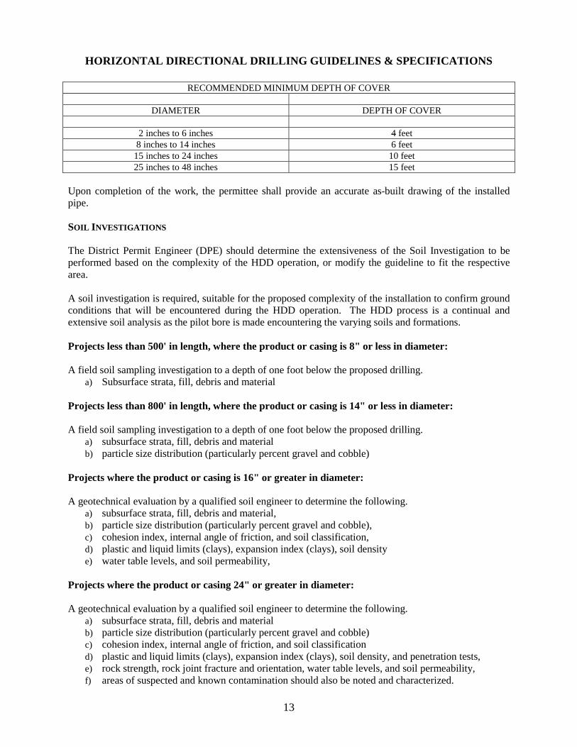
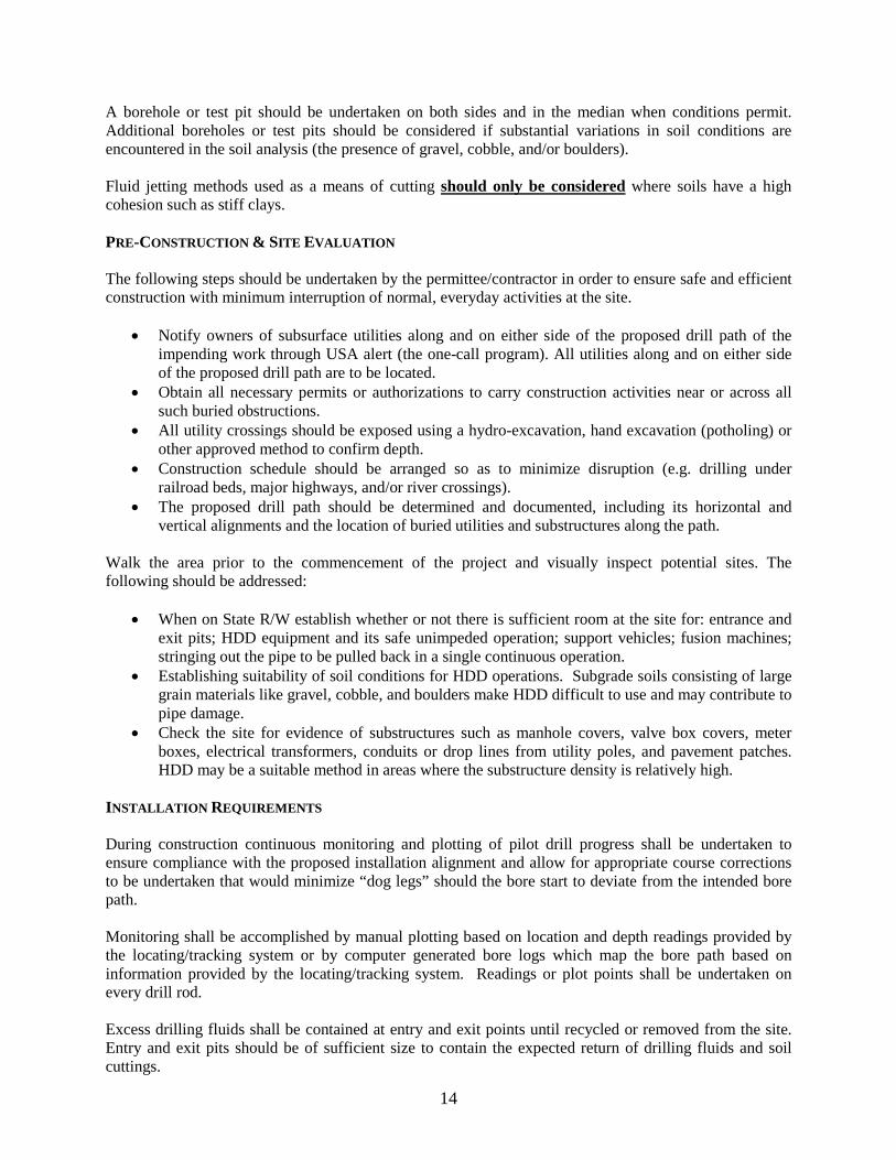
HORIZONTAL DIRECTIONAL DRILLING GUIDELINES & SPECIFICATIONS
RECOMMENDED MINIMUM DEPTH OF COVER
DIAMETER DEPTH OF COVER
2 inches to 6 inches 4 feet 8 inches to 14 inches 6 feet
15 inches to 24 inches 10 feet 25 inches to 48 inches 15 feet
Upon completion of the work, the permittee shall provide an accurate as-built drawing of the installed pipe. SOIL INVESTIGATIONS The District Permit Engineer (DPE) should determine the extensiveness of the Soil Investigation to be performed based on the complexity of the HDD operation, or modify the guideline to fit the respective area. A soil investigation is required, suitable for the proposed complexity of the installation to confirm ground conditions that will be encountered during the HDD operation. The HDD process is a continual and extensive soil analysis as the pilot bore is made encountering the varying soils and formations. Projects less than 500' in length, where the product or casing is 8" or less in diameter: A field soil sampling investigation to a depth of one foot below the proposed drilling.
a) Subsurface strata, fill, debris and material Projects less than 800' in length, where the product or casing is 14" or less in diameter: A field soil sampling investigation to a depth of one foot below the proposed drilling.
a) subsurface strata, fill, debris and material b) particle size distribution (particularly percent gravel and cobble)
Projects where the product or casing is 16" or greater in diameter: A geotechnical evaluation by a qualified soil engineer to determine the following.
a) subsurface strata, fill, debris and material, b) particle size distribution (particularly percent gravel and cobble), c) cohesion index, internal angle of friction, and soil classification, d) plastic and liquid limits (clays), expansion index (clays), soil density e) water table levels, and soil permeability,
Projects where the product or casing 24" or greater in diameter: A geotechnical evaluation by a qualified soil engineer to determine the following.
a) subsurface strata, fill, debris and material b) particle size distribution (particularly percent gravel and cobble) c) cohesion index, internal angle of friction, and soil classification d) plastic and liquid limits (clays), expansion index (clays), soil density, and penetration tests, e) rock strength, rock joint fracture and orientation, water table levels, and soil permeability, f) areas of suspected and known contamination should also be noted and characterized.
14
A borehole or test pit should be undertaken on both sides and in the median when conditions permit. Additional boreholes or test pits should be considered if substantial variations in soil conditions are encountered in the soil analysis (the presence of gravel, cobble, and/or boulders). Fluid jetting methods used as a means of cutting should only be considered where soils have a high cohesion such as stiff clays. PRE-CONSTRUCTION & SITE EVALUATION The following steps should be undertaken by the permittee/contractor in order to ensure safe and efficient construction with minimum interruption of normal, everyday activities at the site.
• Notify owners of subsurface utilities along and on either side of the proposed drill path of the impending work through USA alert (the one-call program). All utilities along and on either side of the proposed drill path are to be located.
• Obtain all necessary permits or authorizations to carry construction activities near or across all such buried obstructions.
• All utility crossings should be exposed using a hydro-excavation, hand excavation (potholing) or other approved method to confirm depth.
• Construction schedule should be arranged so as to minimize disruption (e.g. drilling under railroad beds, major highways, and/or river crossings).
• The proposed drill path should be determined and documented, including its horizontal and vertical alignments and the location of buried utilities and substructures along the path.
Walk the area prior to the commencement of the project and visually inspect potential sites. The following should be addressed:
• When on State R/W establish whether or not there is sufficient room at the site for: entrance and exit pits; HDD equipment and its safe unimpeded operation; support vehicles; fusion machines; stringing out the pipe to be pulled back in a single continuous operation.
• Establishing suitability of soil conditions for HDD operations. Subgrade soils consisting of large grain materials like gravel, cobble, and boulders make HDD difficult to use and may contribute to pipe damage.
• Check the site for evidence of substructures such as manhole covers, valve box covers, meter boxes, electrical transformers, conduits or drop lines from utility poles, and pavement patches. HDD may be a suitable method in areas where the substructure density is relatively high.
INSTALLATION REQUIREMENTS During construction continuous monitoring and plotting of pilot drill progress shall be undertaken to ensure compliance with the proposed installation alignment and allow for appropriate course corrections to be undertaken that would minimize “dog legs” should the bore start to deviate from the intended bore path. Monitoring shall be accomplished by manual plotting based on location and depth readings provided by the locating/tracking system or by computer generated bore logs which map the bore path based on information provided by the locating/tracking system. Readings or plot points shall be undertaken on every drill rod. Excess drilling fluids shall be contained at entry and exit points until recycled or removed from the site. Entry and exit pits should be of sufficient size to contain the expected return of drilling fluids and soil cuttings.
15
The permittee shall ensure that all drilling fluids are disposed of in a manner acceptable to the appropriate local, state, or federal regulatory agencies. When drilling in contaminated ground the drilling fluid shall be tested for contamination and disposed of appropriately. Restoration of damage to any highway or non-highway facility caused by escaping (“fracout”) drilling fluid, or the directional drilling operation, shall be the responsibility of the permittee. To minimize heaving during pullback, the pull back rate shall be determined which maximizes the removal of soil cuttings and minimizes compaction of the ground surrounding the borehole. The pullback rate shall also minimize overcutting of the borehole during the back reaming operation to ensure excessive voids are not created resulting in post installation settlement. The permittee shall, prior to and upon completion of the directional drill, establish a Survey Grid Line and provide monitoring as outlined in their submitted detailed monitoring plan. Subsurface monitoring points shall be utilized to provide early indications of settlement as large voids may not materialize during drilling due to pavement bridging. Should pavement heaving or settlement occur, sawcutting and replacement of the asphalt shall be the responsibility of the permittee. To prevent future settlement should the drilling operation be unsuccessful the permittee shall ensure the backfill of any void(s) with grout or backfilled by other means. PERMITTEE/CONTRACTOR RESPONSIBILITIES The plans set submittal should contain the following information in support of the permit application.
1. Location of entry and exit point. 2. Equipment and pipe layout areas. 3. Proposed drill path alignment (both plan & profile view). 4. Location, elevations and proposed clearances of all utility crossings and structures. 5. Proposed Depth of cover. 6. **Soil analysis. 7. Product material (HDPE/steel), length, diameter-wall thickness, reamer diameter. 8. Detailed pipe calculations, confirming ability of product pipe to withstand installation loads and
long term operational loads including H20. 9. Proposed composition of drilling fluid (based on soil analysis) viscosity and density. 10. Drilling fluid pumping capacity, pressures and flow rates proposed. 11. State right-of-way lines, property, and other utility right-of-way or easement lines. 12. Elevations. 13. Type of tracking method/system. 14. Survey Grid establishment for monitoring ground surface movement (settlement or heave) due to
the drilling operation. Note: ** May be waived by the District Permit Engineer on HDD jobs of less than 6" in diameter and on a transverse crossing less than 150' in length. ADDITIONAL PERMIT CONDITIONS SHALL BE SET FORTH IN THE SPECIAL PROVISIONS OF THE PERMIT. LOCATING AND TRACKING EFFECTIVE JANUARY 1, 2000, LOCATING AND TRACKING OF THE REAMER DURING THE BACK-REAMING PROCESS IS REQUIRED.
16
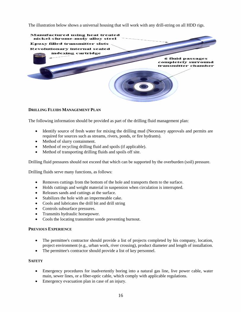
The illustration below shows a universal housing that will work with any drill-string on all HDD rigs.
DRILLING FLUIDS MANAGEMENT PLAN The following information should be provided as part of the drilling fluid management plan:
• Identify source of fresh water for mixing the drilling mud (Necessary approvals and permits are required for sources such as streams, rivers, ponds, or fire hydrants).
• Method of slurry containment. • Method of recycling drilling fluid and spoils (if applicable). • Method of transporting drilling fluids and spoils off site.
Drilling fluid pressures should not exceed that which can be supported by the overburden (soil) pressure. Drilling fluids serve many functions, as follows:
• Removes cuttings from the bottom of the hole and transports them to the surface. • Holds cuttings and weight material in suspension when circulation is interrupted. • Releases sands and cuttings at the surface. • Stabilizes the hole with an impermeable cake. • Cools and lubricates the drill bit and drill string • Controls subsurface pressures. • Transmits hydraulic horsepower. • Cools the locating transmitter sonde preventing burnout.
PREVIOUS EXPERIENCE
• The permittee's contractor should provide a list of projects completed by his company, location, project environment (e.g., urban work, river crossing), product diameter and length of installation.
• The permittee's contractor should provide a list of key personnel. SAFETY
• Emergency procedures for inadvertently boring into a natural gas line, live power cable, water main, sewer lines, or a fiber-optic cable, which comply with applicable regulations.
• Emergency evacuation plan in case of an injury.
17
CONTINGENCY PLANS The Contingency plan shall address the containment and removal, of an inadvertent return or spill (e.g., drilling fluids, and hydraulic fluids). COMMUNICATION PLAN The communication plan should address the following:
• The phone numbers for communication with owner or his representative on the site. • Identification of all key personnel which will be responsible for ensuring that the communications
plan is followed. DRILLING OPERATIONS The following paragraphs provide general remarks and rules of thumb related to the directional boring method, as well as specific details regarding various stages of the installation process.
• The drill path alignment should be as straight as possible to minimize the fractional resistance during pullback and maximize the length of the pipe that can be installed during a single pull.
• The radius of curvature is determined by the bending characteristics of the product line, and it is increasing with diameter.
• If a drill hole beneath a road must be abandoned, the hole should be backfilled with grout or bentonite to prevent future subsidence.
EQUIPMENT SETUP AND SITE LAYOUT
• Sufficient space is required on the rig side to safely set up and operate the equipment. • Sufficient space should be allocated to fabricate the product pipeline into one string, thus
enabling the pull back to be conducted in a single continuous operation.
DRILLING AND BACK-REAMING
• Drilling mud shall be used during drilling and back reaming operations. Using exclusively water may cause collapse of the borehole in unconsolidated soils, while in clays, the use of water may cause swelling and subsequent jamming of the product.
• Heaving may occur when attempting to back ream too large of a hole. This can be avoided by using several pre-reams to gradually enlarge the hole to the desired diameter.
• The conduit must be sealed at both ends with a cap or a plug to prevent water, drilling fluids and other foreign materials from entering the pipe as it is being pulled back.
• Pipe rollers, skates or other protective devices should be used to prevent damage to the pipe from the edges of the pit during pullback, eliminate ground drag or reduce pulling force and subsequently reduce the stress on the product.
• The drilling mud in the annular region should not be removed after installation, but permitted to solidify and provide support for the pipe and neighboring soil.
BREAK-AWAY PULLING HEAD Some utility companies require the use of breakaway swivels to limit the amount of force used when pulling HDPE products.
18
PROTECTIVE COATINGS In an HDD installation, the product pipe may be exposed to extra abrasion during pullback. When installing a steel pipe, a form of coating which provides a corrosion barrier as well as an abrasion barrier is recommended during the operation, the coating should be well bonded and have a hard smooth surface to resist soil stresses and reduce friction, respectively. A recommended type of coating for steel pipes is mill applied Fusion Bonded Epoxy. DRILLING FLUID - COLLECTION AND DISPOSAL PRACTICES Drilling fluids, additives and their Material Safety Data Sheets (MSDS) shall be identified within the contractors submittal permit package.
• Excess drilling fluids shall be contained within a lined pit or containment pound, until removed from the site.
• When an area of contaminated ground is encountered, the slurry shall be tested for contamination and disposed of in a manner, which meets Local, State and/or Federal requirements.
• Precautions shall be taken to keep drilling fluids out of the streets, manholes, sanitary and storm sewers, and other drainage systems, including streams and rivers.
• The contractor shall make all diligent efforts to minimize the amount of drilling fluids and cuttings spilled during the drilling operation, and shall provide complete clean-up of all drilling mud overflows or spills.
SITE RESTORATION AND POST CONSTRUCTION EVALUATION All surfaces affected by the work shall be restored to their pre-existing conditions. The permittee/contractor shall provide a set of as-built drawings to include both alignment and profile. Drawings should be constructed from actual field readings. Raw data shall be submitted as part of the “As-Built” document. The contractor shall stipulate the tracking method used to ensure the data was captured.
19
MICROTUNNELING
Micro-tunneling is a hybrid of the tunneling industry (miniaturization of tunnel boring machines) and the pipeline industry where pipe jacking has been used for more than 100 years. It is a special construction method suitable for many conditions where open cut construction methods are not cost effective, too disruptive, or not physically possible. MICRO-TUNNELING PLAN SET SUBMITTAL The plan set submittal shall consist of two separate submittals, by the Owner of the installation and by the owner's contractor. The submittal by the owning agency shall contain the following plans and information:
1. Drive lengths 2. Proposed depth 3. Shaft; jacking and receiving shafts, manhole construction, shaft backfill, and shoring removal;
• Type of shaft; a) Sheet Pile b) Beams and Lagging c) Trench Box d) Auger Drilled and Lined e) Caissons
4. Intermediate jacking stations; • Number of Stations;
a) Required by Specifications b) On site
5. Geotechnical; including ground water information • Geotechnical evaluation by a qualified soil engineer to determine the following;
a) Boring logs & plan locations of borings and cross sections, Subsurface strata, fill and ground water elevations
b) Particle size distribution (particularly percent rock and cobble), c) Cohesion indexes, internal angle of friction, and soil classification, d) Plastic and liquid limits (clays), expansion index (clays), soil density, and penetration
tests, e) Rock strength; rock joint fracture and orientation, water table levels, and soil
permeability, e) Areas of suspected and known contamination should also be noted and characterized.
• Should the soil investigation determine the presence of rock, cobbles, and/or boulders, determination of the following information would be required; a) Depth and extent of rock b) Rock type c) Rock strength d) Rock joint/fracture spacing e) Hardness f) RQD g) Estimated range of sizes & frequency of occurrence of cobbles and boulders.
Boreholes or test pits for road crossings shall be undertaken on both sides with one or more additional boreholes or test pits in the median where conditions permit. Additional boreholes or test pits should be considered if substantial variation in soil conditions are encountered. Where a proposed installation parallels an existing road, boreholes or test pits should be undertaken at approximately 250 to 410 feet
20
intervals. CONTRACTOR’S SUBMITTAL Shall contain the following plans and information:
1. Shaft; soil stability at portals and ground improvement. 2. Dewatering plans for jacking and receiving shafts, if any. 3. Shoring design for jacking and receiving shafts. 4. Survey control plan: lasers, laser mounting, laser checking. 5. Ground surface settlement monuments and subsurface settlement monuments monitoring
program plan. • Buried points
a) Rebar points, or b) MPBX (Multi-point borehole extensometers)
6. Recycling information; slurry mix and polymer additives, slurry separation plant type, and spoils disposal;
a) Removal of slurry in dump trucks. b) Removal of slurry in tankers. c) Settlement ponds. d) Muck piles on site.
7. Contingency plan information; a) Ground improvement plans when required at portals and/or behind thrust block/reaction
wall due to weak and unstable soil conditions. b) Obstruction removal through emergency (911) shafts or other means. c) Mechanical breakdowns and recovery of the MTBM through 911 shafts or other means. d) Control of hydrofracture and slurry loss. e) Remediation of loss of ground and excessive ground surface settlement.
21
PIPE RAMMING Pipe Ramming pit requirements are identical to those for Bore & Jack. Establishment of a survey-grid line is required. Before any project begins, exploration bore-holes and a complete geotechnical investigation shall be conducted to determine possible difficulties in order to determine the drilling trajectory. The casing shall be rammed open ended, except when the diameter is 6” or smaller. Pipes 6” or smaller may be rammed open ended or closed. A soil shoe may be installed on the leading edge of the casing, either by fabrication on site or obtained from the manufacturer. A soil shoe shall not be utilized on those installations at depths or 18” or less from the surface. Lubrication shall only be utilized to reduce friction and increase production. The amount of lubrication directed to the outside of the pipe shall only be of a sufficient amount required to fill the void between the outside of the pipe and soil, as created by the soil shoe. Lubrication to the inside of the casing shall only be an amount adequate to assist in spoil removal when the ram is completed. Welding of the casing at joints shall be as per the manufacturer’s recommendations. The use of straps at each joint on pipe diameters of 12” or larger is required as is the use of the manufacturer’s specified welding wire or rod. Spoil removal for rammed encasements of 30” in diameter or less, may utilize pressurized air or water. Air pressure shall not exceed 150 psi and water pressure shall not exceed 300 psi. Encasements larger than 30” in diameter shall have the spoils removed by other means than by pressurizing of the pipe, such as, manual, auguring, vacuum, washing or other means. The Receiving Pit shall be steel plated entirely when the spoils are to be removed from within the encasement by means of air or water pressurized methods.
22
PIPE BURSTING
Pipe Bursting operations generally are only performed by the owning utility when they have exceeded the operating capacity of their existing facilities. In most cases pipe bursting allows the utility owners the advantage of upgrading their existing facilities by up to 50%. On installations of diameters 12” or greater it is necessary to establish a survey-grid line and establish the existing elevation points over the existing area of installation. A soil analysis should be required and review of the information to identify any locations of difficulty, density, water table, changes in soil formation that could present or create greater friction resistance. Request information of the proposed project as to:
1. The ratio of the proposed upgrade to determine difficulty, generally up to 25% increase in diameter is common. An increase of 25% - 50% is considered challenging, and an increase of 50% or greater is considered experimental.
2. The existing depth of cover, “rule of thumb” depth of cover should be at least 10X the difference
in the upgrade of the existing diameter to be burst.
3. Whether or not the existing line has been viewed by video, do not allow line to be burst blind.
4. Is this proposed line straight or are there bends in the line.
5. If bends are existing in the line, the location of the bend will have to be excavated and new pits re-established at those locations.
6. Require that the contractor provide a list of equipment to be on site to handle an emergency, in
the event that bypass pumping is required to maintain the existing service in the event of a problem.
7. As to what method will be utilized (static, pneumatic, burst and jack, or hydraulic).