Embed Size (px)
Citation preview
Nevion Nordre Kullerød 1 3241 Sandefjord Norway Tel: +47 33 48 99 99
nevion.com
HD-TD-10GMX-6 / HD-TD-10GDX-6
A multiplexer/de-multiplexer pair for up to six HD-SDI streams plus two SD-SDI streams, transported over a 10G fiber link.
User manual
Rev. C
HD-TD-10GMX-6 / HD-TD-10GDX-6 Rev. C
nevion.com | 2
Nevion Support
Nevion Europe
P.O. Box 1020 3204 Sandefjord, Norway
Support phone 1: +47 33 48 99 97 Support phone 2: +47 90 60 99 99
Nevion USA
1600 Emerson Avenue Oxnard, CA 93033, USA
Toll free North America: (866) 515-0811 Outside North America: +1 (805) 247-8560
E-mail: [email protected]
See http://www.nevion.com/support/ for service hours for customer support globally.
Revision history
Current revision of this document is the uppermost in the table below.
Rev. Repl. Date Sign Change description
C B 2013-05-15 CC Changed GPI outputs
B A 2013-12-13 TB Revised power consumption figures and corrected pin numbering for the GPIO alarm lines.
A - 2013-10-30 TB Initial revision
HD-TD-10GMX-6 / HD-TD-10GDX-6 Rev. C
nevion.com | 3
Contents
Revision history ........................................................................................................ 2
1 Product overview ................................................................................................... 4 1.1 Product variants ............................................................................................................ 4
2 Connections .......................................................................................................... 5
3 Configuration and control ...................................................................................... 6 3.1 In Multicon ..................................................................................................................... 6 3.1.1 Laser on/off (mux side only) ....................................................................................... 7 3.1.2 Sticky vs. Normal error indication ............................................................................... 7 3.1.3 Signal integrity ............................................................................................................ 8 3.1.4 Expected video format ................................................................................................ 9 3.2 In manual mode (DIP switch control) ............................................................................10 3.3 With GPIO pins (mux side only) ...................................................................................10
4 Monitoring ............................................................................................................ 11 4.1 In Multicon ....................................................................................................................11 4.2 On front mounted LEDs ................................................................................................13 4.2.1 Exceptions/special conditions for the LEDS ..............................................................13 4.3 On GPIO pins ...............................................................................................................14
5 Technical data ..................................................................................................... 15 5.1 Engineering drawings ...................................................................................................15 5.2 Specifications ...............................................................................................................16
General environmental requirements for Nevion equipment .................................. 17
Product Warranty.................................................................................................... 18
Appendix A Materials declaration and recycling information .................................. 19 A.1 Materials declaration ....................................................................................................19 A.2 Recycling information ...................................................................................................19
HD-TD-10GMX-6 / HD-TD-10GDX-6 Rev. C
nevion.com | 4
1 Product overview
The HD-TD-10GMX-6 / HD-TD-10GDX-6 pair of cards is a Flashlink solution for transporting up to six HD-SDI and two SD-SDI video streams over a single 10 Gb/s link.
Six ports accept all common HD-SDI/SD-SDI/ASI formats and standards, and the transport solution is completely transparent with any combination of formats and standards. The same applies to ports 7 and 8 as well, except that they are limited to video streams up to 270 Mb/s only. It is thus possible to transport up to six HD-SDI streams plus two SD-SDI streams simultaneously. Each of the HD-SDI input streams can however be substituted for an SD-SDI stream to transport up to eight SD-SDI streams with a single pair of cards
In combination with other Nevion Flashlink products (SD-TD-MX-4 and SD-TD-DX-4) that can pack up to four SD-SDI streams into a single HD-SDI stream, it is possible to transport up to 26 SD-SDI streams over a single 10 Gb/s link. Physically this combination will fit in a single Flashlink frame at each end of the 10 Gb/s link.
The inputs have built-in error detection and video format detection. For each of the input or output channels there is also the option to trigger a Multicon Gyda alarm if the current video format doesn’t match what the operator has indicated as normal.
The SFP+ optical transmitter and receiver module can easily be replaced. If new SFP+ modules bring significant improvements over the current ones, a quick and simple upgrade path exists.
1.1 Product variants At present there are no sub-variants of the HD-TD-10GMX-6 / HD-TD-10GDX-6 pair.
Note that although other SFP modules will fit physically, only the Nevion branded dual SFP+ modules for the HD-TD-10GMX-6 / HD-TD-10GDX-6 will work correctly.
HD-TD-10GMX-6 / HD-TD-10GDX-6 Rev. C
nevion.com | 5
2 Connections
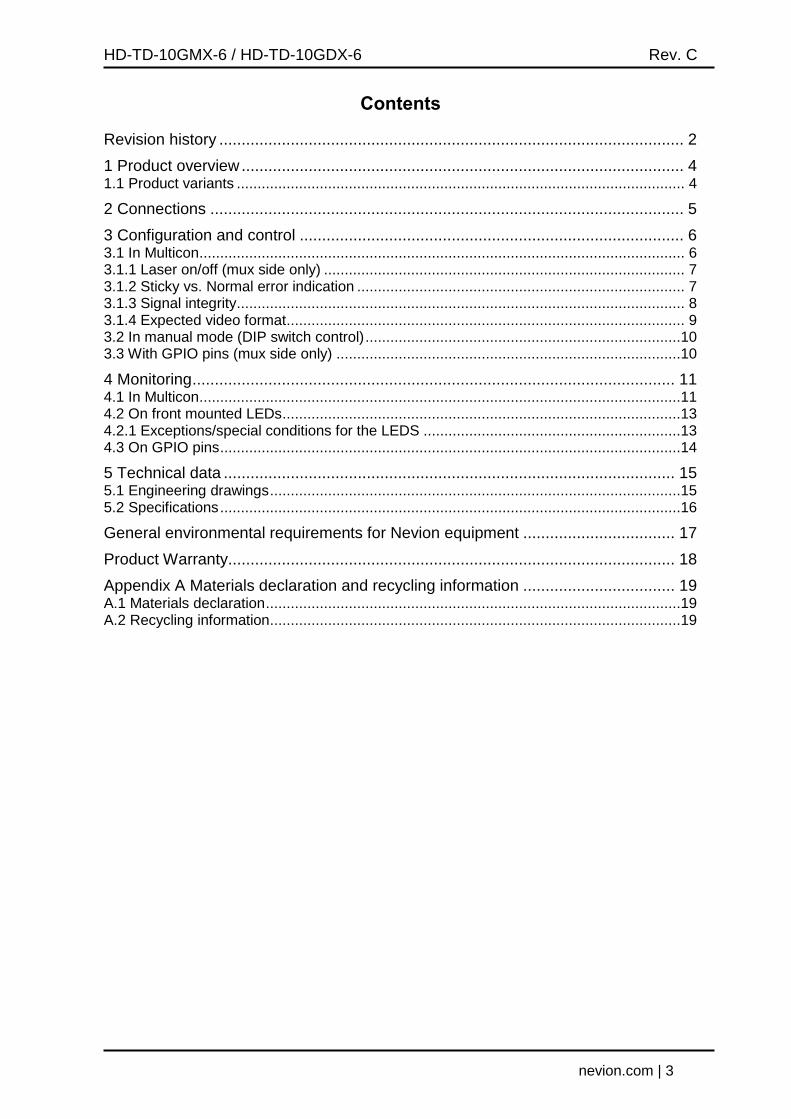
Figure 1: The backplane, HD-TD-10G-C1
The backplane HD-TD-10G-C1 is used for both the mux and the de-mux modules. All external connections are made via the backplane.
The backplane occupies two slots in the Flashlink frame, and the module will then go in the rightmost of the two slots.
Function Label Connector type
HD/SD-SDI channel 1 Ch1 BNC
HD/SD-SDI channel 2 Ch2 BNC
HD/SD-SDI channel 3 Ch3 BNC
HD/SD-SDI channel 4 Ch4 BNC
HD/SD-SDI channel 5 Ch5 BNC
HD/SD-SDI channel 6 Ch6 BNC
SD-SDI channel 7 Ch7 BNC
SD-SDI channel 8 Ch8 BNC
TX optical port w/cover OPT1 ---
RX optical port w/cover OPT2 ---
GPI outputs GPIO TP45, pin 2 (card status, open when alarm) TP45, pin 3 (optical alarm), TP45, pin 6 (channel 1-8 status, closed when alarm)
GPI inputs GPIO TP45, pin 1 (laser disable, active low)
GPI GND GPIO TP45, pin 8
--- Ethernet TP45
Table 1: Connector functions
HD-TD-10GMX-6 / HD-TD-10GDX-6 Rev. C
nevion.com | 6
3 Configuration and control
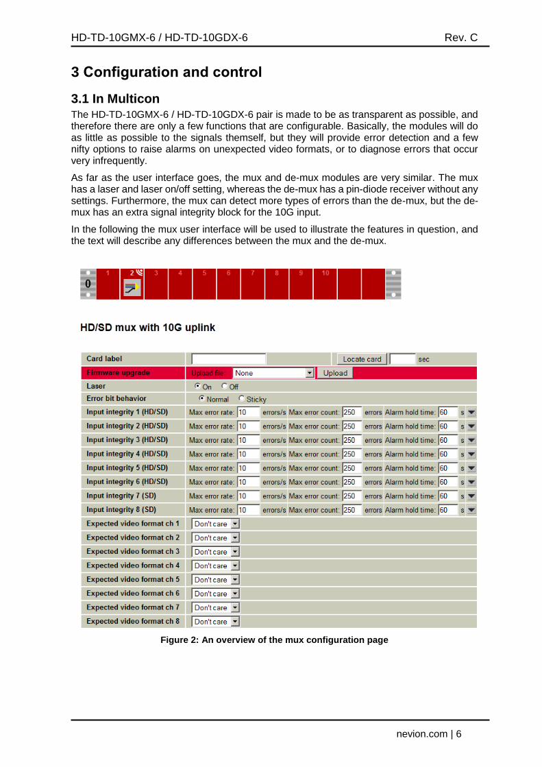
3.1 In Multicon The HD-TD-10GMX-6 / HD-TD-10GDX-6 pair is made to be as transparent as possible, and therefore there are only a few functions that are configurable. Basically, the modules will do as little as possible to the signals themself, but they will provide error detection and a few nifty options to raise alarms on unexpected video formats, or to diagnose errors that occur very infrequently.
As far as the user interface goes, the mux and de-mux modules are very similar. The mux has a laser and laser on/off setting, whereas the de-mux has a pin-diode receiver without any settings. Furthermore, the mux can detect more types of errors than the de-mux, but the de-mux has an extra signal integrity block for the 10G input.
In the following the mux user interface will be used to illustrate the features in question, and the text will describe any differences between the mux and the de-mux.
Figure 2: An overview of the mux configuration page
HD-TD-10GMX-6 / HD-TD-10GDX-6 Rev. C
nevion.com | 7
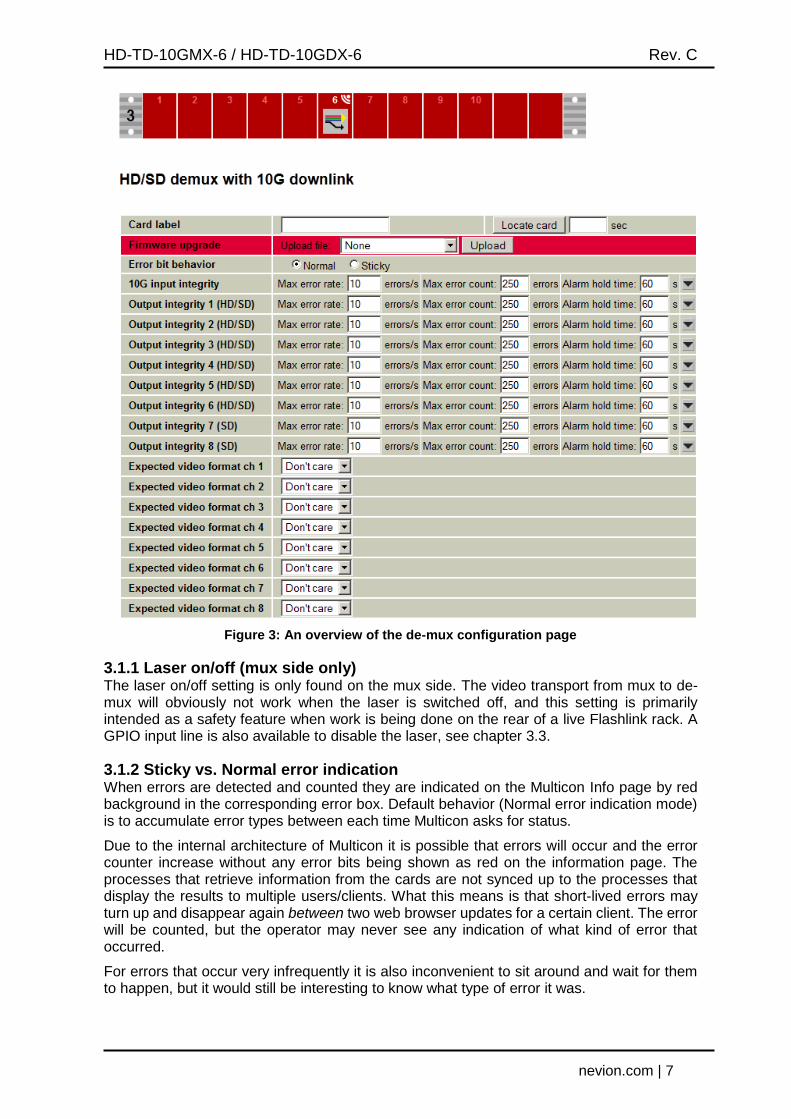
Figure 3: An overview of the de-mux configuration page
3.1.1 Laser on/off (mux side only) The laser on/off setting is only found on the mux side. The video transport from mux to de-mux will obviously not work when the laser is switched off, and this setting is primarily intended as a safety feature when work is being done on the rear of a live Flashlink rack. A GPIO input line is also available to disable the laser, see chapter 3.3.
3.1.2 Sticky vs. Normal error indication When errors are detected and counted they are indicated on the Multicon Info page by red background in the corresponding error box. Default behavior (Normal error indication mode) is to accumulate error types between each time Multicon asks for status.
Due to the internal architecture of Multicon it is possible that errors will occur and the error counter increase without any error bits being shown as red on the information page. The processes that retrieve information from the cards are not synced up to the processes that display the results to multiple users/clients. What this means is that short-lived errors may turn up and disappear again between two web browser updates for a certain client. The error will be counted, but the operator may never see any indication of what kind of error that occurred.
For errors that occur very infrequently it is also inconvenient to sit around and wait for them to happen, but it would still be interesting to know what type of error it was.
HD-TD-10GMX-6 / HD-TD-10GDX-6 Rev. C
nevion.com | 8
As a solution for both these situations the mux and de-mux provides the Sticky error indication mode. In this mode the error bits will only be cleared when the operator resets the error counter from the Multicon Info page. The error counters will still only count the number of fields or frames that actually contains errors. This way it is possible to diagnose the error even a long time after the error situation has been rectified. Note however that if several errors have occurred since the last counter reset it will not be possible to tell when or for how long each was present, or if they occurred at the same time or not.
3.1.3 Signal integrity
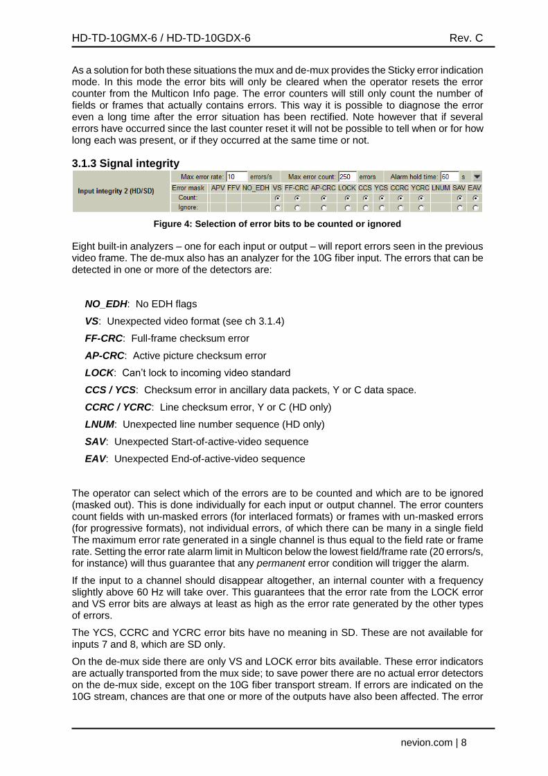
Figure 4: Selection of error bits to be counted or ignored
Eight built-in analyzers – one for each input or output – will report errors seen in the previous video frame. The de-mux also has an analyzer for the 10G fiber input. The errors that can be detected in one or more of the detectors are:
NO_EDH: No EDH flags
VS: Unexpected video format (see ch 3.1.4)
FF-CRC: Full-frame checksum error
AP-CRC: Active picture checksum error
LOCK: Can’t lock to incoming video standard
CCS / YCS: Checksum error in ancillary data packets, Y or C data space.
CCRC / YCRC: Line checksum error, Y or C (HD only)
LNUM: Unexpected line number sequence (HD only)
SAV: Unexpected Start-of-active-video sequence
EAV: Unexpected End-of-active-video sequence
The operator can select which of the errors are to be counted and which are to be ignored (masked out). This is done individually for each input or output channel. The error counters count fields with un-masked errors (for interlaced formats) or frames with un-masked errors (for progressive formats), not individual errors, of which there can be many in a single field The maximum error rate generated in a single channel is thus equal to the field rate or frame rate. Setting the error rate alarm limit in Multicon below the lowest field/frame rate (20 errors/s, for instance) will thus guarantee that any permanent error condition will trigger the alarm.
If the input to a channel should disappear altogether, an internal counter with a frequency slightly above 60 Hz will take over. This guarantees that the error rate from the LOCK error and VS error bits are always at least as high as the error rate generated by the other types of errors.
The YCS, CCRC and YCRC error bits have no meaning in SD. These are not available for inputs 7 and 8, which are SD only.
On the de-mux side there are only VS and LOCK error bits available. These error indicators are actually transported from the mux side; to save power there are no actual error detectors on the de-mux side, except on the 10G fiber transport stream. If errors are indicated on the 10G stream, chances are that one or more of the outputs have also been affected. The error
HD-TD-10GMX-6 / HD-TD-10GDX-6 Rev. C
nevion.com | 9
bits for the fiber transport stream are limited to LOCK error and FF-CRC error. This FF-CRC bit is not the same as FF-CRC for normal SDI video, but rather a mapping of several internal checksums into one error bit. This error counter behaves as the others in the sense that the error count per second is limited to slightly more than 60.
Note that when an input is missing, only the LOCK error bit is set, not the other error bits. Generally it is therefore a good idea to count the LOCK error bit, as the other error bits will indicate that everything is OK when the input signal has indeed been lost. Individual reclocker alarms also exist, and while a single observation of loss of lock is enough to trigger these alarms, the lock status is only sampled when Multicon asks the card for its current status. The update frequency will thus depend on how many other cards are in the system, and glitches in lock status will not necessarily be reported to Multicon to trigger an alarm there.
3.1.4 Expected video format
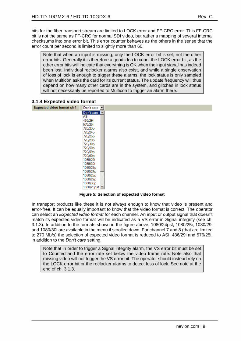
Figure 5: Selection of expected video format
In transport products like these it is not always enough to know that video is present and error-free. It can be equally important to know that the video format is correct. The operator can select an Expected video format for each channel. An input or output signal that doesn’t match its expected video format will be indicated as a VS error in Signal integrity (see ch. 3.1.3). In addition to the formats shown in the figure above, 1080/24psf, 1080/25i, 1080/29i and 1080/30i are available in the menu if scrolled down. For channel 7 and 8 (that are limited to 270 Mb/s) the selection of expected video format is reduced to ASI, 486/29i and 576/25i, in addition to the Don’t care setting.
Note that in order to trigger a Signal integrity alarm, the VS error bit must be set to Counted and the error rate set below the video frame rate. Note also that missing video will not trigger the VS error bit. The operator should instead rely on the LOCK error bit or the reclocker alarms to detect loss of lock. See note at the end of ch. 3.1.3.
HD-TD-10GMX-6 / HD-TD-10GDX-6 Rev. C
nevion.com | 10
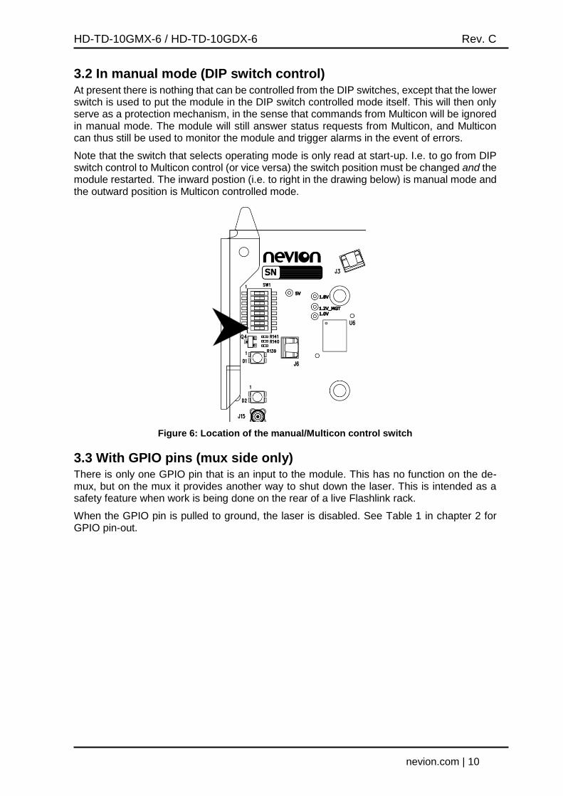
3.2 In manual mode (DIP switch control) At present there is nothing that can be controlled from the DIP switches, except that the lower switch is used to put the module in the DIP switch controlled mode itself. This will then only serve as a protection mechanism, in the sense that commands from Multicon will be ignored in manual mode. The module will still answer status requests from Multicon, and Multicon can thus still be used to monitor the module and trigger alarms in the event of errors.
Note that the switch that selects operating mode is only read at start-up. I.e. to go from DIP switch control to Multicon control (or vice versa) the switch position must be changed and the module restarted. The inward postion (i.e. to right in the drawing below) is manual mode and the outward position is Multicon controlled mode.
Figure 6: Location of the manual/Multicon control switch
3.3 With GPIO pins (mux side only) There is only one GPIO pin that is an input to the module. This has no function on the de-mux, but on the mux it provides another way to shut down the laser. This is intended as a safety feature when work is being done on the rear of a live Flashlink rack.
When the GPIO pin is pulled to ground, the laser is disabled. See Table 1 in chapter 2 for GPIO pin-out.
HD-TD-10GMX-6 / HD-TD-10GDX-6 Rev. C
nevion.com | 11
4 Monitoring
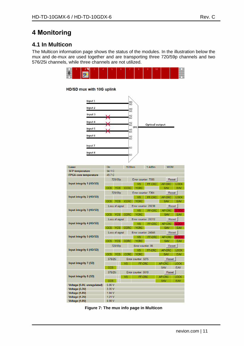
4.1 In Multicon The Multicon information page shows the status of the modules. In the illustration below the mux and de-mux are used together and are transporting three 720/59p channels and two 576/25i channels, while three channels are not utilized.
Figure 7: The mux info page in Multicon
HD-TD-10GMX-6 / HD-TD-10GDX-6 Rev. C
nevion.com | 12
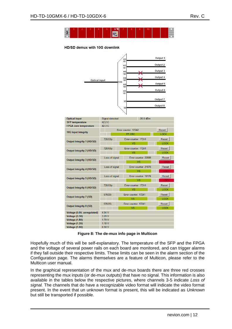
Figure 8: The de-mux info page in Multicon
Hopefully much of this will be self-explanatory. The temperature of the SFP and the FPGA and the voltage of several power rails on each board are monitored, and can trigger alarms if they fall outside their respective limits. These limits can be seen in the alarm section of the Configuration page. The alarms themselves are a feature of Multicon, please refer to the Multicon user manual.
In the graphical representation of the mux and de-mux boards there are three red crosses representing the mux inputs (or de-mux outputs) that have no signal. This information is also available in the tables below the respective pictures, where channels 3-5 indicate Loss of signal. The channels that do have a recognizable video format will indicate the video format present. In the event that un unknown format is present, this will be indicated as Unknown but still be transported if possible.
HD-TD-10GMX-6 / HD-TD-10GDX-6 Rev. C
nevion.com | 13
Each channel also has its own error bit indicators. The boxes that have a red background color indicate an error that is currently detected and counted. A green background will indicate that the particular error is set to be counted, but that the error is currently not detected. Errors that are not to be counted (i.e. set to Ignore) will be presented as the error bit name on a gray background color (no example shown here), regardless if the error is currently detected or not. Error types that are not supported for that particular channel will be shown as blank boxes with gray backgrounds. Most web browser will expand the boxes that contain text at the expense of these blank ones, as the examples above show.
4.2 On front mounted LEDs
Table 2: LED states and what they mean
The LEDs on the board are not labeled in silk screen. Users familiar with the Flashlink range will know that the upper LED (closest to the red handle) is the status LED. The order of the rest of the LEDs corresponds to the order in the table above.
Note that the configuration of the Expected video format will influence the way the LEDs behave. The “Don’t care” condition mentioned in the table above refers to the “Expected video format” settings, and only those channels assigned a specific video format will affect the LEDs. Conversely, setting all channels to “Don’t care” will result in LED 3 and LED 4 always being green, even if all video signals are missing.
4.2.1 Exceptions/special conditions for the LEDS The locate command will make all four LEDs blink on and off synchronously to quickly identify the module in a larger installation. The condition of the card is not otherwise affected by the command, only the appearance of the LEDs will change. The LEDs return to their normal states and functions after the special locate condition has timed out.
Red LED Orange LED Green LED No light
Card status FPGA not loaded, or at least one voltage outside legal levels
--- Module is OK Module has no power
Mux: Laser De-mux: Pin
Laser missing or failed Input missing or signal below -28 dBm
Laser present but turned off Input signal below -25 dBm
Laser present and turned on Input signal stronger than -25 dBm
Module has no power
Inputs 1-4 At least one of the channels 1-4 that are not set to Don’t care is missing lock
At least one of the channels 1-4 that are not set to Don’t care is locked to the wrong video format
Channels 1-4 are all either set to Don’t care or are present and have the right video format
Module has no power
Inputs 5-8 At least one of the channels 5-8 that are not set to Don’t care is missing lock
At least one of the channels 5-8 that are not set to Don’t care is locked to the wrong video format
Channels 5-8 are all either set to Don’t care or are present and have the right video format
Module has no power
HD-TD-10GMX-6 / HD-TD-10GDX-6 Rev. C
nevion.com | 14
4.3 On GPIO pins There are three GPIO status lines, see Table 1: Connector functions on page 5. One is a general card status alarm; the connection to ground is open when the card has either detected a critical fault or is powered off, the connection to ground is closed when the module is in normal operation. This GPIO pin effectively follows the status LED described in Table 2 in the previous chapter.
There is also one GPIO status line for the optical input/ output alarm. Then there is one alarm, which reflects LEDs 3 and 4 as described in Table 2; a green LED gives a closed connection to the ground pin, while a red or orange LED gives an open connection to the ground pin.
HD-TD-10GMX-6 / HD-TD-10GDX-6 Rev. C
nevion.com | 15
5 Technical data
5.1 Engineering drawings
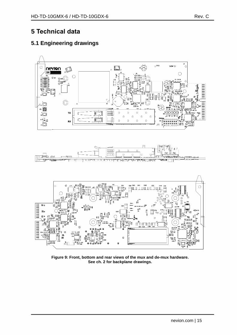
Figure 9: Front, bottom and rear views of the mux and de-mux hardware. See ch. 2 for backplane drawings.
HD-TD-10GMX-6 / HD-TD-10GDX-6 Rev. C
nevion.com | 16
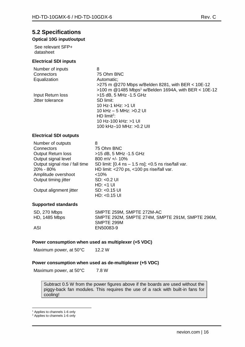
5.2 Specifications Optical 10G input/output
See relevant SFP+ datasheet
Electrical SDI inputs
Number of inputs 8 Connectors 75 Ohm BNC Equalization Automatic;
>275 m @270 Mbps w/Belden 8281, with BER < 10E-12 >100 m @1485 Mbps1 w/Belden 1694A, with BER < 10E-12
Input Return loss >15 dB, 5 MHz -1.5 GHz Jitter tolerance SD limit:
10 Hz-1 kHz: >1 UI 10 kHz – 5 MHz: >0.2 UI HD limit2: 10 Hz-100 kHz: >1 UI 100 kHz–10 MHz: >0.2 UII
Electrical SDI outputs
Number of outputs 8 Connectors 75 Ohm BNC Output Return loss >15 dB, 5 MHz -1.5 GHz Output signal level 800 mV +/- 10% Output signal rise / fall time 20% - 80%
SD limit: [0.4 ns – 1.5 ns]; <0.5 ns rise/fall var. HD limit: <270 ps, <100 ps rise/fall var.
Amplitude overshoot <10% Output timing jitter SD: <0.2 UI
HD: <1 UI Output alignment jitter SD: <0.15 UI
HD: <0.15 UI
Supported standards
SD, 270 Mbps SMPTE 259M, SMPTE 272M-AC HD, 1485 Mbps SMPTE 292M, SMPTE 274M, SMPTE 291M, SMPTE 296M,
SMPTE 299M ASI EN50083-9
Power consumption when used as multiplexer (+5 VDC)
Maximum power, at 50°C 12.2 W
Power consumption when used as de-multiplexer (+5 VDC)
Maximum power, at 50°C 7.8 W
Subtract 0.5 W from the power figures above if the boards are used without the piggy-back fan modules. This requires the use of a rack with built-in fans for cooling!
1 Applies to channels 1-6 only 2 Applies to channels 1-6 only
HD-TD-10GMX-6 / HD-TD-10GDX-6 Rev. C
nevion.com | 17
General environmental requirements for Nevion equipment
1. The equipment will meet the guaranteed performance specification under the following environmental conditions:
- Operating room temperature range:
0°C to 45°C
- Operating relative humidity range: <90% (non-condensing) 2. The equipment will operate without damage under the following environmental
conditions: - Temperature range: -10°C to 55°C - Relative humidity range: <95% (non-condensing)

HD-TD-10GMX-6 / HD-TD-10GDX-6 Rev. C
nevion.com | 18
Product Warranty
The warranty terms and conditions for the product(s) covered by this manual follow the General Sales Conditions by Nevion, which are available on the company web site:
www.nevion.com

HD-TD-10GMX-6 / HD-TD-10GDX-6 Rev. C
nevion.com | 19
Appendix A Materials declaration and recycling information
A.1 Materials declaration For product sold into China after 1st March 2007, we comply with the “Administrative Measure on the Control of Pollution by Electronic Information Products”. In the first stage of this legislation, content of six hazardous materials has to be declared. The table below shows the required information.
組成名稱
Part Name
Toxic or hazardous substances and elements
鉛
Lead (Pb)
汞
Mercury (Hg)
镉
Cadmium (Cd)
六价铬
Hexavalent Chromium
(Cr(VI))
多溴联苯
Polybrominated biphenyls
(PBB)
多溴二苯醚
Polybrominated diphenyl ethers
(PBDE)
HD-TD-10GMX-6 HD-TD-10GDX-6
O O O O O O
O: Indicates that this toxic or hazardous substance contained in all of the homogeneous materials for this part is below the limit requirement in SJ/T11363-2006. X: Indicates that this toxic or hazardous substance contained in at least one of the homogeneous materials used for this part is above the limit requirement in SJ/T11363-2006.
This is indicated by the product marking:
A.2 Recycling information Nevion provides assistance to customers and recyclers through our web site http://www.nevion.com/. Please contact Nevion’s Customer Support for assistance with recycling if this site does not show the information you require.
Where it is not possible to return the product to Nevion or its agents for recycling, the following general information may be of assistance:
Before attempting disassembly, ensure the product is completely disconnected from power and signal connections.
All major parts are marked or labeled to show their material content.
Depending on the date of manufacture, this product may contain lead in solder.
Some circuit boards may contain battery-backed memory devices.


![f x , y D 6 x^2 y^2; ParametricPlot3D@8 tD, r Sin tD, 6 r ...€¦ · In[16]:= f@x_, y_D = 6-x^2- y^2; ParametricPlot3D@8r*Cos@tD, r*Sin@tD, 6-r^2](https://img.pdfslide.us/doc/110x75/5eac02e2262c4a53ec404774/f-x-y-d-6-x2-y2-parametricplot3d8-td-r-sin-td-6-r-in16-fx-yd.jpg)