Embed Size (px)
Citation preview
Hydraulic
Post DriverModel HD-10 & HD-10-H
Shaver Manufacturing Company
103 South Washington Avenue, Graettinger, Iowa 51342
Phone: (712) 859-3293 — Fax: (712) 859-3294 — www.shavermfg.com
Safety
Operation
Maintenance
Repair
Troubleshooting
Parts
Operator’s Manual
ContentsSafety . . . . . . . . . . . . . . . . . . . . . . . . . . . . . . . 2
Safety Alert Symbols . . . . . . . . . . . . . . . . . . 3Safety Icon Nomenclature . . . . . . . . . . . . . . 3
Safety Warnings. . . . . . . . . . . . . . . . . . . . . . . 4General Safety . . . . . . . . . . . . . . . . . . . . . . . 4Hazard Avoidance . . . . . . . . . . . . . . . . . . . . 4Hydraulic Hoses . . . . . . . . . . . . . . . . . . . . . 5
Introduction . . . . . . . . . . . . . . . . . . . . . . . . . . 6Product Information . . . . . . . . . . . . . . . . . . . 6
Specifications. . . . . . . . . . . . . . . . . . . . . . . . . 6Assembly Procedure . . . . . . . . . . . . . . . . . . . 7
Recommended Tools . . . . . . . . . . . . . . . . . . 7Unpacking . . . . . . . . . . . . . . . . . . . . . . . . . . 8Assembly . . . . . . . . . . . . . . . . . . . . . . . . . . . 8
Main Carriage Channel . . . . . . . . . . . . . . . 9Stabilizer Legs . . . . . . . . . . . . . . . . . . . . . 10Base Plate . . . . . . . . . . . . . . . . . . . . . . . . 10Hydraulic Valve . . . . . . . . . . . . . . . . . . . . 13Safety Stop Adjustment . . . . . . . . . . . . . . 16Rubber Debris Guard . . . . . . . . . . . . . . . 17Safety Arm . . . . . . . . . . . . . . . . . . . . . . . . 18Document Storage Tube . . . . . . . . . . . . . 21
Post Driver Operation . . . . . . . . . . . . . . . . . 21Operational Safety Tips . . . . . . . . . . . . . . . 21Operating Instructions . . . . . . . . . . . . . . . . 22
Mounting . . . . . . . . . . . . . . . . . . . . . . . . . 22Preparing to Drive a Post. . . . . . . . . . . . . 23Driving a Post. . . . . . . . . . . . . . . . . . . . . . 24Dismounting Post Driver . . . . . . . . . . . . . 27
Troubleshooting . . . . . . . . . . . . . . . . . . . . . . 29Storage. . . . . . . . . . . . . . . . . . . . . . . . . . . . . 29Service Procedures . . . . . . . . . . . . . . . . . . . 30
Three-Point Hitch/Post Driver Assembly . . 30Main Carriage Channel Disassembly . . . . 31Drive Cylinder Seal Replacement . . . . . . . 33Main Carriage Channel Assembly. . . . . . . 35Forward and Side Tilt Cylinder Maintenance . . . . . . . . . . . . . . . . . . . . . . . 38
Cylinder Disassembly . . . . . . . . . . . . . . . 38Cylinder Assembly. . . . . . . . . . . . . . . . . . 39
Three-Point Hitch/Post Driver Assembly . . 41
Service Parts . . . . . . . . . . . . . . . . . . . . . . . . 42Driver Assembly. . . . . . . . . . . . . . . . . . . . . 42Manual Base Plate Assembly . . . . . . . . . . 44Hydraulic Base Plate Assembly . . . . . . . . 46Three-Point Hitch Assembly . . . . . . . . . . . 48Hydraulic Hoses . . . . . . . . . . . . . . . . . . . . 48Safety Arm Assembly . . . . . . . . . . . . . . . . 48Replacement Decals . . . . . . . . . . . . . . . . . 49Document Tube . . . . . . . . . . . . . . . . . . . . . 49Hydraulic Control Valves . . . . . . . . . . . . . . 50Single Control Lever Valve. . . . . . . . . . . . 50Triple Control Lever Valve . . . . . . . . . . . . 51
Drive Cylinder Assembly . . . . . . . . . . . . . . 52Expanded View of Safety Lever Assembly . . . . . . . . . . . . . . . . . . . . . . . . . . 52Tilt Cylinder Assembly . . . . . . . . . . . . . . . . 53
Limited Warranty . . . . . . . . . . . . . . . . . . . . . 54Warranty Card . . . . . . . . . . . . . . . . . . . . . . . 55
SafetyMost work related accidents are caused byfailure to observe basic safety rules orprecautions. An accident can often beavoided by recognizing potentially hazardoussituations before an accident occurs. As youassemble and operate the Shaver Post Driver,you must be alert to potential hazards. Youshould also have the necessary training, skills,and tools to perform this assembly procedure.
Improper operation and maintenance of thisimplement could result in a dangeroussituation that could cause injury or death.
Do not assemble, operate, or maintainthe Shaver Post Driver until you read andunderstand the information contained inthis manual.
Safety precautions and warnings areprovided in this manual and on theproduct. If these hazard warnings arenot heeded, bodily injury or death couldoccur to you or to other persons.
2
Shaver Manufacturing Company cannotanticipate every possible circumstance thatmight involve a potential hazard. Thewarnings in this supplement and on theproduct are, therefore, not all-inclusive. If amethod of operation not specificallyrecommended by Shaver ManufacturingCompany is used, you must satisfy yourselfthat it is safe for you and for others. Youshould also ensure that the implement willnot be damaged or be made unsafe by themethods that you choose.
The information, specifications, and illustrationsin this supplement are based on theinformation that was available at the time thismaterial was written and can change at anytime.
Safety Alert Symbols
TThhee safety alert symbol meansAttention! Become Alert! Your Safetyis Involved.
Hazards are identified by the “Safety AlertSymbol” and are followed by the signal word“WARNING”.
WARNING: Indicates a potentially hazardoussituation which, if not avoided, could result indeath or serious injury.
Potential damage situations are identified by thesignal words “IMPORTANT NOTICE”.
IMPORTANT NOTICEIndicates that equipment or property damagecan result if instructions are not followed.
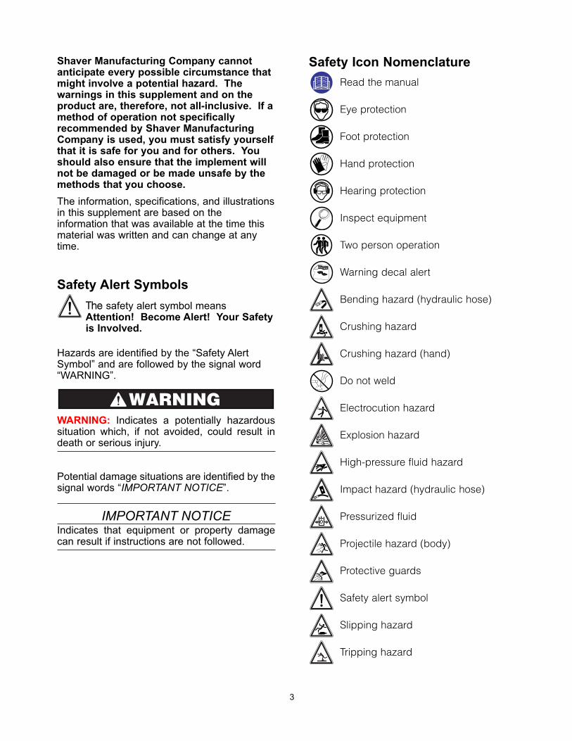
Safety Icon Nomenclature
Read the manual
Eye protection
Foot protection
Hand protection
Hearing protection
Inspect equipment
Two person operation
Warning decal alert
Bending hazard (hydraulic hose)
Crushing hazard
Crushing hazard (hand)
Do not weld
Electrocution hazard
Explosion hazard
High-pressure fluid hazard
Impact hazard (hydraulic hose)
Pressurized fluid
Projectile hazard (body)
Protective guards
Safety alert symbol
Slipping hazard
Tripping hazard
N INGAR
WARNING
3
44
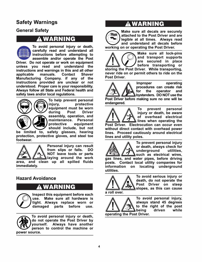
Safety Warnings
General Safety
To avoid personal injury or death,carefully read and understand allinstructions before attempting toassemble and/or operate the Post
Driver. Do not operate or work on equipmentunless you read and understand theinstructions and warnings in this and all otherapplicable manuals. Contact ShaverManufacturing Company. if any of theinstructions provided are unclear or notunderstood. Proper care is your responsibility.Always follow all State and Federal health andsafety laws and/or local regulations.
To help prevent personalinjury, protectiveequipment must be wornduring Post Driverassembly, operation, andmaintenance. Personalprotective equipmentshould include, but not
be limited to, safety glasses, hearingprotection, protective gloves, and steel toefootwear.
Personal injury can resultfrom slips or falls. DONOT leave tools or partslaying around the work
area, and clean up all spilled fluidsimmediately.
Hazard Avoidance
Inspect this equipment before eachuse. Make sure all hardware istight. Always replace worn ordamaged parts before use.
To avoid personal injury or death,do not operate the Post Driver byyourself. Always have anotherperson to control the machine or
power source.
Make sure all decals are securelyattached to the Post Driver and arelegible at all times. Always readand understand all decals before
working on or operating the Post Driver.
Make sure all lock-pinsand transport supportsare secured in placebefore transporting or
storing the Post Driver.. While transporting,never ride on or permit others to ride on thePost Driver..
Improper operatingprocedures can create riskfor the operator andbystanders. DO NOTuse the
Post Driver before making sure no one will beendangered.
To prevent personalinjury or death, be awareof overhead electricallines when operating the
Post Driver. Electrocution can occur evenwithout direct contact with overhead powerlines. Proceed cautiously around electricallines and utility poles.
To prevent personal injuryor death, always check forunderground utilities,such as electrical wires,
gas lines, and water pipes, before drivingposts. Contact local utility companies forinformation on locating undergroundutilities.
To avoid serious injury ordeath, do not operate thePost Driver on steepslopes, as this can cause
a roll over.
To avoid personal injury,always stand 45 degreesto the right of the postbeing driven while
operating the Post Driver.
N INGAR
WARNING
WARNING
WARNING
5
Potential pinch points.Keep hands clear of PostDriver while operating. Never place hand(s) on
top of a post when inserting it into the Post Driver. Always close the safety armbefore driving the post.
To avoid personal injurydo not attempt to clean,adjust, or lubricate thePost Driver while it is in
motion.
The rubber debris guard helpsshield the operator from flyingdebris that may be generatedduring post driving. To avoid
personal injury, make sure the rubber debrisguard is securely attached to the Post Driverbefore driving posts.
To avoid personal injury or death,do not modify the Post Driver bywelding, drilling, or grinding. Donot expose to extreme heat, such
as from a torch.
The main carriage channelassembly is tall and heavy. Toavoid tip over, resulting in seriousinjury or death, leave the overhead
lifting device attached to the main carriagechannel while assembling components.
To avoid serious injury or death, thesafety arm must be installed after thePost Driver has been mounted on amachine, or the freestanding Post
Driver has been secured to prevent tipping.
Hydraulic Hoses
Avoid damaging hydraulic hoses.Avoid sharp bends and kinks whenrouting hydraulic hoses. Using abent or kinked hose will cause
severe back-pressure. Sharp bends andkinks can internally damage the hose,leading to premature hose failure, resultingin personal injury.
Do not drop heavy objects onhoses. A sharp impact may causeinternal damage to the hose.Applying pressure to a damaged
hose may cause it to rupture, resulting inpersonal injury.
Mismatched couplingsand hoses can cause thecoupling to violentlydisconnect from the hose
when placed under pressure; separatingwith sudden, extreme force which can resultin property damage, personal injury, ordeath.
Replace a hose if any of the followingconditions are present:
- End fittings that are damaged or leaking
- Outer coverings that are chafed or cut
- Wire shields that are exposed
- Outer coverings that are ballooning
- Flexible part of the hoses that are kinked
- End fittings that are displaced
Pressure can be trappedin a hydraulic system.Trapped pressure cancause sudden movement
of an attachment. Use caution whendisconnecting hydraulic lines or fittings.High-pressure oil that is released can causea hose to move violently while spraying oil.
Escaping high-pressure fluid canpenetrate the skin, causing seriousinjury. Relieve pressure beforeunhooking hoses. Check/tighten
all connections before activating hydraulics.Never use your hand to check for leaks.
WARNING
WARNING
WARNING
6
IntroductionThe Shaver Manufacturing Company wouldlike to congratulate you on your purchase ofthe Shaver Hydraulic Post Driver. You haveselected the best Post Driver in its class. Theclean design and uncomplicated workingprinciple have made Shaver the largest sellingPost Driver in the country.
The Shaver HD-10 (manual tilt adjustment) andHD-10-H (hydraulic tilt adjustment) HydraulicPost Driver is a durable piece of equipmentthat, with regular maintenance, will providemany years of service.
This manual provides information regardingassembly, operation, and maintenance. It isimportant to read and become familiar withthis manual before assembling or operatingthe Shaver Hydraulic Post Driver.
NOTE: For other valuable information on farmequipment operation and safety, refer to thefollowing resources.
• Farm Equipment ManufacturersAssociation (FEMA)http://www.farmequip.org/home
• National Ag Safety Databasehttp://www.cdc.gov/nasd/
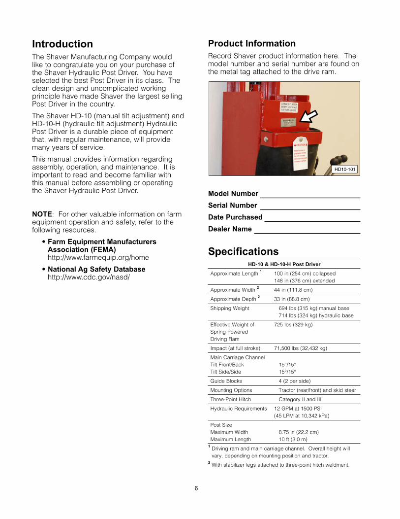
Product Information
Record Shaver product information here. Themodel number and serial number are found onthe metal tag attached to the drive ram.
Model Number
Serial Number
Date Purchased
Dealer Name
SpecificationsHD-10 & HD-10-H Post Driver
Approximate Length 1 100 in (254 cm) collapsed148 in (376 cm) extended
Approximate Width 2 44 in (111.8 cm)
Approximate Depth 2 33 in (88.8 cm)
Shipping Weight 694 lbs (315 kg) manual base714 lbs (324 kg) hydraulic base
Effective Weight of 725 lbs (329 kg)Spring Powered Driving Ram
Impact (at full stroke) 71,500 lbs (32,432 kg)
Main Carriage ChannelTilt Front/Back 15°/15°Tilt Side/Side 15°/15°
Guide Blocks 4 (2 per side)
Mounting Options Tractor (rear/front) and skid steer
Three-Point Hitch Category II and III
Hydraulic Requirements 12 GPM at 1500 PSI(45 LPM at 10,342 kPa)
Post SizeMaximum Width 8.75 in (22.2 cm)Maximum Length 10 ft (3.0 m)
1 Driving ram and main carriage channel. Overall height willvary, depending on mounting position and tractor.
2 With stabilizer legs attached to three-point hitch weldment.
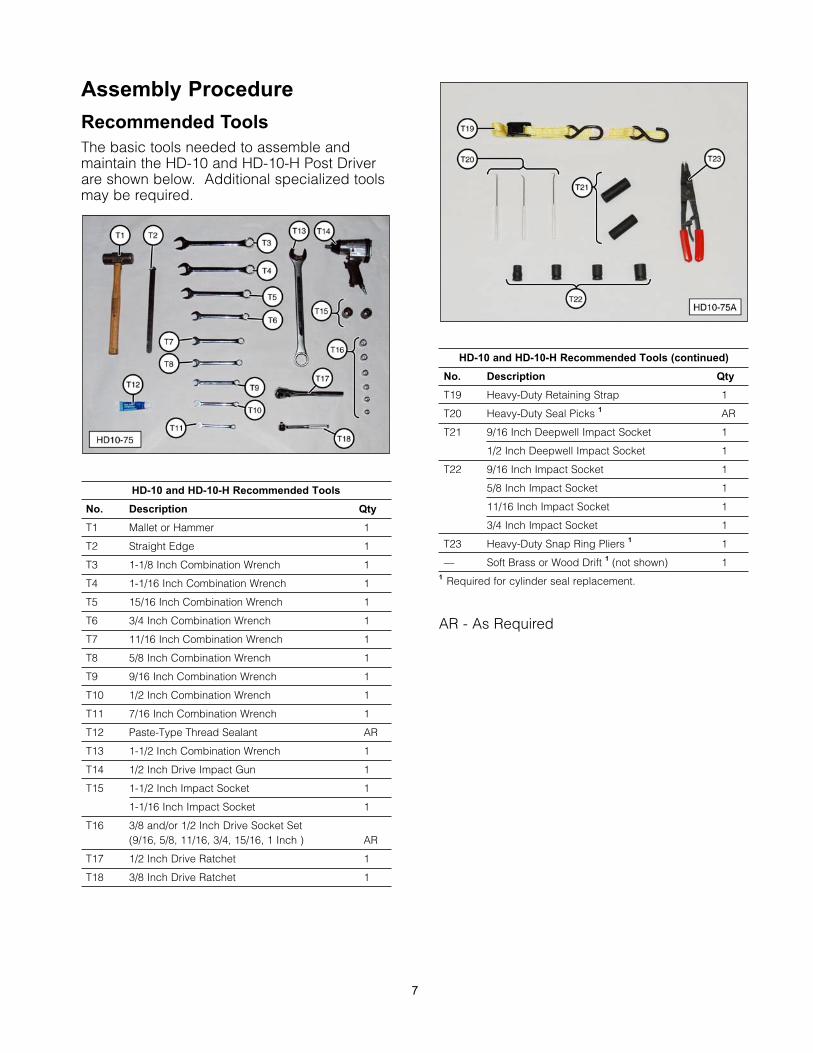
Assembly Procedure
Recommended Tools
The basic tools needed to assemble andmaintain the HD-10 and HD-10-H Post Driverare shown below. Additional specialized toolsmay be required.
HD-10 and HD-10-H Recommended Tools
No. Description Qty
T1 Mallet or Hammer 1
T2 Straight Edge 1
T3 1-1/8 Inch Combination Wrench 1
T4 1-1/16 Inch Combination Wrench 1
T5 15/16 Inch Combination Wrench 1
T6 3/4 Inch Combination Wrench 1
T7 11/16 Inch Combination Wrench 1
T8 5/8 Inch Combination Wrench 1
T9 9/16 Inch Combination Wrench 1
T10 1/2 Inch Combination Wrench 1
T11 7/16 Inch Combination Wrench 1
T12 Paste-Type Thread Sealant AR
T13 1-1/2 Inch Combination Wrench 1
T14 1/2 Inch Drive Impact Gun 1
T15 1-1/2 Inch Impact Socket 1
1-1/16 Inch Impact Socket 1
T16 3/8 and/or 1/2 Inch Drive Socket Set (9/16, 5/8, 11/16, 3/4, 15/16, 1 Inch ) AR
T17 1/2 Inch Drive Ratchet 1
T18 3/8 Inch Drive Ratchet 1
HD-10 and HD-10-H Recommended Tools (continued)
No. Description Qty
T19 Heavy-Duty Retaining Strap 1
T20 Heavy-Duty Seal Picks 1 AR
T21 9/16 Inch Deepwell Impact Socket 1
1/2 Inch Deepwell Impact Socket 1
T22 9/16 Inch Impact Socket 1
5/8 Inch Impact Socket 1
11/16 Inch Impact Socket 1
3/4 Inch Impact Socket 1
T23 Heavy-Duty Snap Ring Pliers 1 1
— Soft Brass or Wood Drift 1 (not shown) 11 Required for cylinder seal replacement.
AR - As Required
7
Unpacking
Due to the size and weight of thePost Driver, two people are requiredfor the assembly procedures.
The Post Driver is shipped in several sections:the driving ram assembly, base plateassembly, short channel bracket, hose andvalve carton, safety arm carton, and on modelHD-10-H, the tilt cylinder carton.
Before starting the unpackingprocedure, make sure theoverhead lifting device or materialhandling device (forklift) has
adequate lifting capacity. Follow all safetyrecommendations when unpacking the PostDriver. Some components are heavy andcan cause serious injury or death if notadequately supported during removal andassembly.
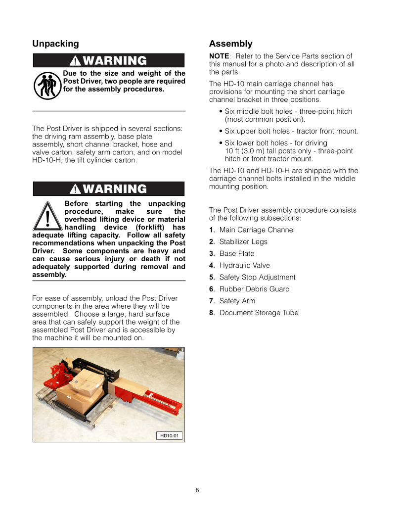
For ease of assembly, unload the Post Drivercomponents in the area where they will beassembled. Choose a large, hard surfacearea that can safely support the weight of theassembled Post Driver and is accessible bythe machine it will be mounted on.
Assembly
NOTE: Refer to the Service Parts section ofthis manual for a photo and description of allthe parts.
The HD-10 main carriage channel hasprovisions for mounting the short carriagechannel bracket in three positions.
• Six middle bolt holes - three-point hitch(most common position).
• Six upper bolt holes - tractor front mount.
• Six lower bolt holes - for driving 10 ft (3.0 m) tall posts only - three-pointhitch or front tractor mount.
The HD-10 and HD-10-H are shipped with thecarriage channel bolts installed in the middlemounting position.
The Post Driver assembly procedure consistsof the following subsections:
1. Main Carriage Channel
2. Stabilizer Legs
3. Base Plate
4. Hydraulic Valve
5. Safety Stop Adjustment
6. Rubber Debris Guard
7. Safety Arm
8. Document Storage Tube
WARNING
WARNING
8
Main Carriage Channel
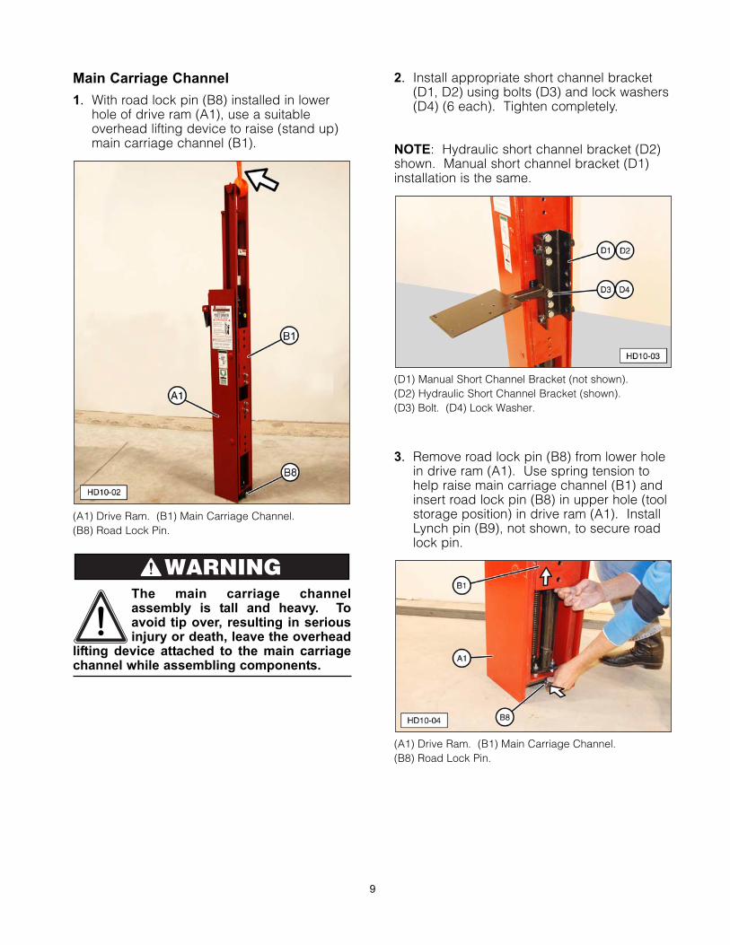
1. With road lock pin (B8) installed in lowerhole of drive ram (A1), use a suitableoverhead lifting device to raise (stand up)main carriage channel (B1).
(A1) Drive Ram. (B1) Main Carriage Channel. (B8) Road Lock Pin.
The main carriage channelassembly is tall and heavy. Toavoid tip over, resulting in seriousinjury or death, leave the overhead
lifting device attached to the main carriagechannel while assembling components.
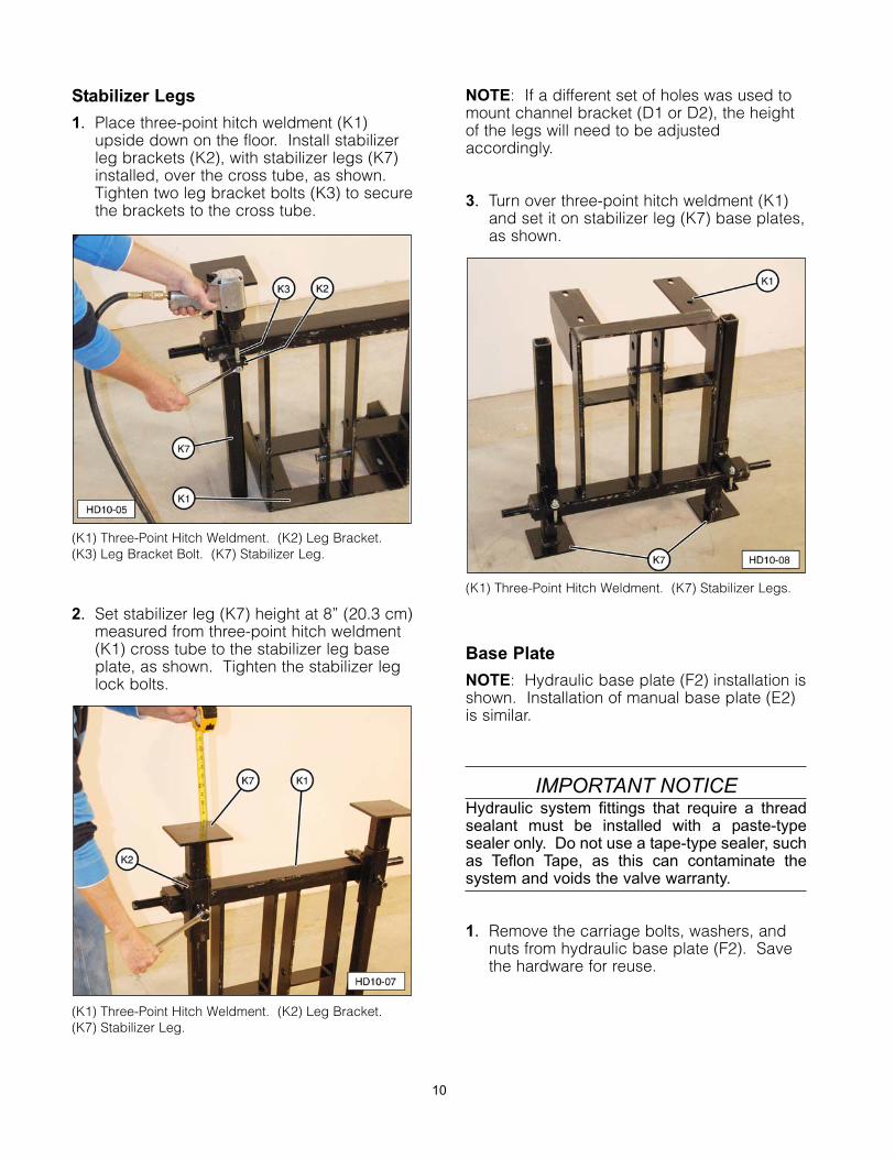
2. Install appropriate short channel bracket(D1, D2) using bolts (D3) and lock washers(D4) (6 each). Tighten completely.
NOTE: Hydraulic short channel bracket (D2)shown. Manual short channel bracket (D1)installation is the same.
(D1) Manual Short Channel Bracket (not shown). (D2) Hydraulic Short Channel Bracket (shown). (D3) Bolt. (D4) Lock Washer.
3. Remove road lock pin (B8) from lower holein drive ram (A1). Use spring tension tohelp raise main carriage channel (B1) andinsert road lock pin (B8) in upper hole (toolstorage position) in drive ram (A1). InstallLynch pin (B9), not shown, to secure roadlock pin.
(A1) Drive Ram. (B1) Main Carriage Channel. (B8) Road Lock Pin.
WARNING
9
Stabilizer Legs
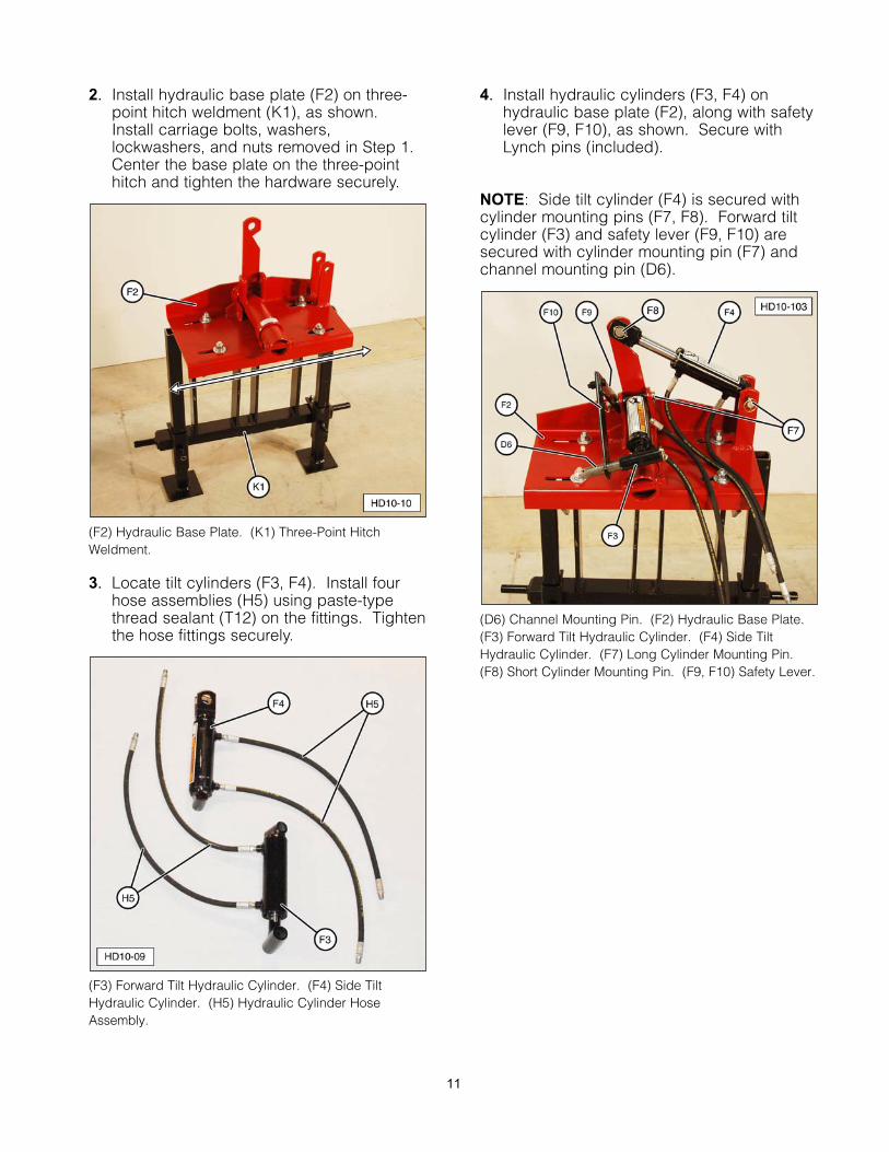
1. Place three-point hitch weldment (K1)upside down on the floor. Install stabilizerleg brackets (K2), with stabilizer legs (K7)installed, over the cross tube, as shown.Tighten two leg bracket bolts (K3) to securethe brackets to the cross tube.
(K1) Three-Point Hitch Weldment. (K2) Leg Bracket.(K3) Leg Bracket Bolt. (K7) Stabilizer Leg.
2. Set stabilizer leg (K7) height at 8” (20.3 cm)measured from three-point hitch weldment(K1) cross tube to the stabilizer leg baseplate, as shown. Tighten the stabilizer leglock bolts.
(K1) Three-Point Hitch Weldment. (K2) Leg Bracket. (K7) Stabilizer Leg.
NOTE: If a different set of holes was used tomount channel bracket (D1 or D2), the heightof the legs will need to be adjustedaccordingly.
3. Turn over three-point hitch weldment (K1)and set it on stabilizer leg (K7) base plates,as shown.
(K1) Three-Point Hitch Weldment. (K7) Stabilizer Legs.
Base Plate
NOTE: Hydraulic base plate (F2) installation isshown. Installation of manual base plate (E2)is similar.
IMPORTANT NOTICEHydraulic system fittings that require a threadsealant must be installed with a paste-typesealer only. Do not use a tape-type sealer, suchas Teflon Tape, as this can contaminate thesystem and voids the valve warranty.
1. Remove the carriage bolts, washers, andnuts from hydraulic base plate (F2). Savethe hardware for reuse.
10
2. Install hydraulic base plate (F2) on three-point hitch weldment (K1), as shown.Install carriage bolts, washers,lockwashers, and nuts removed in Step 1.Center the base plate on the three-pointhitch and tighten the hardware securely.
(F2) Hydraulic Base Plate. (K1) Three-Point HitchWeldment.
3. Locate tilt cylinders (F3, F4). Install fourhose assemblies (H5) using paste-typethread sealant (T12) on the fittings. Tightenthe hose fittings securely.
(F3) Forward Tilt Hydraulic Cylinder. (F4) Side TiltHydraulic Cylinder. (H5) Hydraulic Cylinder HoseAssembly.
4. Install hydraulic cylinders (F3, F4) onhydraulic base plate (F2), along with safetylever (F9, F10), as shown. Secure withLynch pins (included).
NOTE: Side tilt cylinder (F4) is secured withcylinder mounting pins (F7, F8). Forward tiltcylinder (F3) and safety lever (F9, F10) aresecured with cylinder mounting pin (F7) andchannel mounting pin (D6).
(D6) Channel Mounting Pin. (F2) Hydraulic Base Plate. (F3) Forward Tilt Hydraulic Cylinder. (F4) Side TiltHydraulic Cylinder. (F7) Long Cylinder Mounting Pin. (F8) Short Cylinder Mounting Pin. (F9, F10) Safety Lever.
11
The main carriage channelassembly is tall and heavy. Toavoid tip over, resulting in seriousinjury or death, leave the overhead
lifting device attached to the main carriagechannel while assembling components.
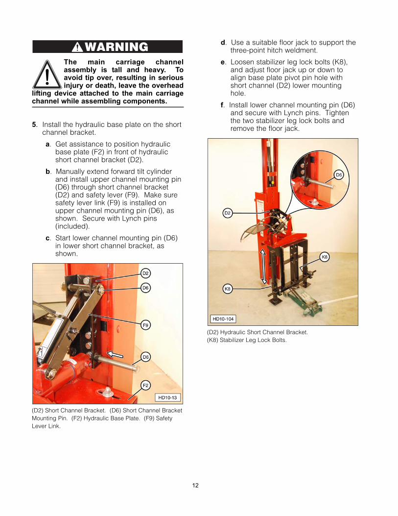
5. Install the hydraulic base plate on the shortchannel bracket.
a. Get assistance to position hydraulicbase plate (F2) in front of hydraulicshort channel bracket (D2).
b. Manually extend forward tilt cylinderand install upper channel mounting pin(D6) through short channel bracket(D2) and safety lever (F9). Make suresafety lever link (F9) is installed onupper channel mounting pin (D6), asshown. Secure with Lynch pins(included).
c. Start lower channel mounting pin (D6)in lower short channel bracket, asshown.
(D2) Short Channel Bracket. (D6) Short Channel BracketMounting Pin. (F2) Hydraulic Base Plate. (F9) SafetyLever Link.
d. Use a suitable floor jack to support thethree-point hitch weldment.
e. Loosen stabilizer leg lock bolts (K8),and adjust floor jack up or down toalign base plate pivot pin hole withshort channel (D2) lower mountinghole.
f. Install lower channel mounting pin (D6)and secure with Lynch pins. Tightenthe two stabilizer leg lock bolts andremove the floor jack.
(D2) Hydraulic Short Channel Bracket. (K8) Stabilizer Leg Lock Bolts.
WARNING
12
NOTE: If using manual base plate (E2)assembly, adjust forward tilt crank (E11) andside tilt crank (E3) to align channel mountingpin holes. Install lower channel mounting pin(D6) first and then upper channel mountingpin. Secure pins with Lynch pins (included).
(D6) Channel Mounting Pin. (E2) Manual Base Plate.(E3) Side Tilt Crank. (E11) Forward Tilt Crank.
Hydraulic Valve
The customer must supply suitable hydraulicquick disconnect fittings for connectingpressure supply hose (G17) and return hose(G20) to the tractor or power supply hydraulicsystem.
IMPORTANT NOTICEHydraulic system fittings that require a threadsealant must be installed with a paste-typesealer only. Do not use a tape-type sealer, suchas Teflon Tape, as this can contaminate thesystem and voids the valve warranty.
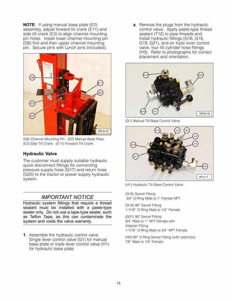
1. Assemble the hydraulic control valve.Single lever control valve (G1) for manualbase plate or triple lever control valve (H1)for hydraulic base plate.
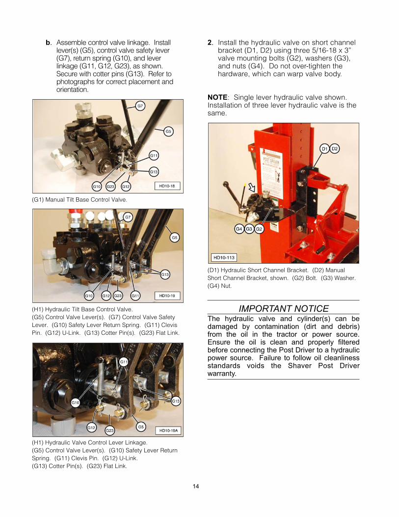
a. Remove the plugs from the hydrauliccontrol valve. Apply paste-type threadsealant (T12) to pipe threads andinstall hydraulic fittings (G16, G18,G19, G21), and on triple lever controlvalve, four tilt cylinder hose fittings(H3). Refer to photographs for correctplacement and orientation.
(G1) Manual Tilt Base Control Valve.
(H1) Hydraulic Tilt Base Control Valve.
(G16) Swivel Fitting:3/4” O-Ring Male to 1” Female NPT.
(G19) 90° Swivel Fitting:1-1/16” O-Ring Male to 1/2” Female.
(G21) 90° Swivel Fitting:3/4” Male to 1” NPT Female with Adapter Fitting:1-1/16” O-Ring Male to 3/4” NPT Female.
(H3) 90° O-Ring Swivel Fitting (with restrictor):7/8” Male to 1/4” Female.
13
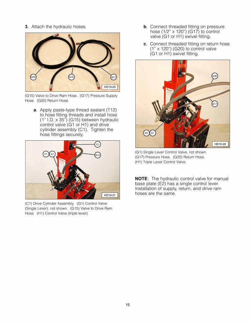
b. Assemble control valve linkage. Installlever(s) (G5), control valve safety lever(G7), return spring (G10), and leverlinkage (G11, G12, G23), as shown.Secure with cotter pins (G13). Refer tophotographs for correct placement andorientation.
(G1) Manual Tilt Base Control Valve.
(H1) Hydraulic Tilt Base Control Valve.(G5) Control Valve Lever(s). (G7) Control Valve SafetyLever. (G10) Safety Lever Return Spring. (G11) ClevisPin. (G12) U-Link. (G13) Cotter Pin(s). (G23) Flat Link.
(H1) Hydraulic Valve Control Lever Linkage. (G5) Control Valve Lever(s). (G10) Safety Lever ReturnSpring. (G11) Clevis Pin. (G12) U-Link. (G13) Cotter Pin(s). (G23) Flat Link.
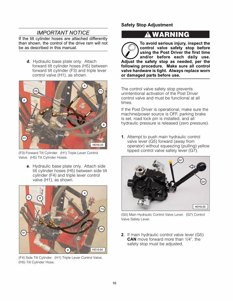
2. Install the hydraulic valve on short channelbracket (D1, D2) using three 5/16-18 x 3”valve mounting bolts (G2), washers (G3),and nuts (G4). Do not over-tighten thehardware, which can warp valve body.
NOTE: Single lever hydraulic valve shown.Installation of three lever hydraulic valve is thesame.
(D1) Hydraulic Short Channel Bracket. (D2) ManualShort Channel Bracket, shown. (G2) Bolt. (G3) Washer.(G4) Nut.
IMPORTANT NOTICEThe hydraulic valve and cylinder(s) can bedamaged by contamination (dirt and debris)from the oil in the tractor or power source.Ensure the oil is clean and properly filteredbefore connecting the Post Driver to a hydraulicpower source. Failure to follow oil cleanlinessstandards voids the Shaver Post Driverwarranty.
14
3. Attach the hydraulic hoses.
(G15) Valve to Drive Ram Hose. (G17) Pressure SupplyHose. (G20) Return Hose.
a. Apply paste-type thread sealant (T12)to hose fitting threads and install hose (1” I.D. x 35”) (G15) between hydrauliccontrol valve (G1 or H1) and drivecylinder assembly (C1). Tighten thehose fittings securely.
(C1) Drive Cylinder Assembly. (G1) Control Valve (Single Lever), not shown. (G15) Valve to Drive RamHose. (H1) Control Valve (triple lever).
b. Connect threaded fitting on pressurehose (1/2” x 120”) (G17) to controlvalve (G1 or H1) swivel fitting.
c. Connect threaded fitting on return hose(1” x 120”) (G20) to control valve (G1 or H1) swivel fitting.
(G1) Single Lever Control Valve, not shown. (G17) Pressure Hose. (G20) Return Hose. (H1) Triple Lever Control Valve.
NOTE: The hydraulic control valve for manualbase plate (E2) has a single control lever.Installation of supply, return, and drive ramhoses are the same.
15
IMPORTANT NOTICEIf the tilt cylinder hoses are attached differentlythan shown, the control of the drive ram will notbe as described in this manual.
d. Hydraulic base plate only. Attachforward tilt cylinder hoses (H5) betweenforward tilt cylinder (F3) and triple levercontrol valve (H1), as shown.
(F3) Forward Tilt Cylinder. (H1) Triple Lever ControlValve. (H5) Tilt Cylinder Hoses.
e. Hydraulic base plate only. Attach sidetilt cylinder hoses (H5) between side tiltcylinder (F4) and triple lever controlvalve (H1), as shown.
(F4) Side Tilt Cylinder. (H1) Triple Lever Control Valve.(H5) Tilt Cylinder Hose.
Safety Stop Adjustment
To avoid serious injury, inspect thecontrol valve safety stop beforeusing the Post Driver the first timeand/or before each daily use.
Adjust the safety stop as needed, per thefollowing procedure. Make sure all controlvalve hardware is tight. Always replace wornor damaged parts before use.
The control valve safety stop preventsunintentional activation of the Post Drivercontrol valve and must be functional at alltimes.
If the Post Driver is operational, make sure themachine/power source is OFF, parking brakeis set, road lock pin is installed, and allhydraulic pressure is released (zero pressure).
1. Attempt to push main hydraulic controlvalve lever (G5) forward (away fromoperator) without squeezing (pulling) yellowtipped control valve safety lever (G7).
(G5) Main Hydraulic Control Valve Lever. (G7) ControlValve Safety Lever.
2. If main hydraulic control valve lever (G5)CAN move forward more than 1/4”, thesafety stop must be adjusted.
WARNING
16
17
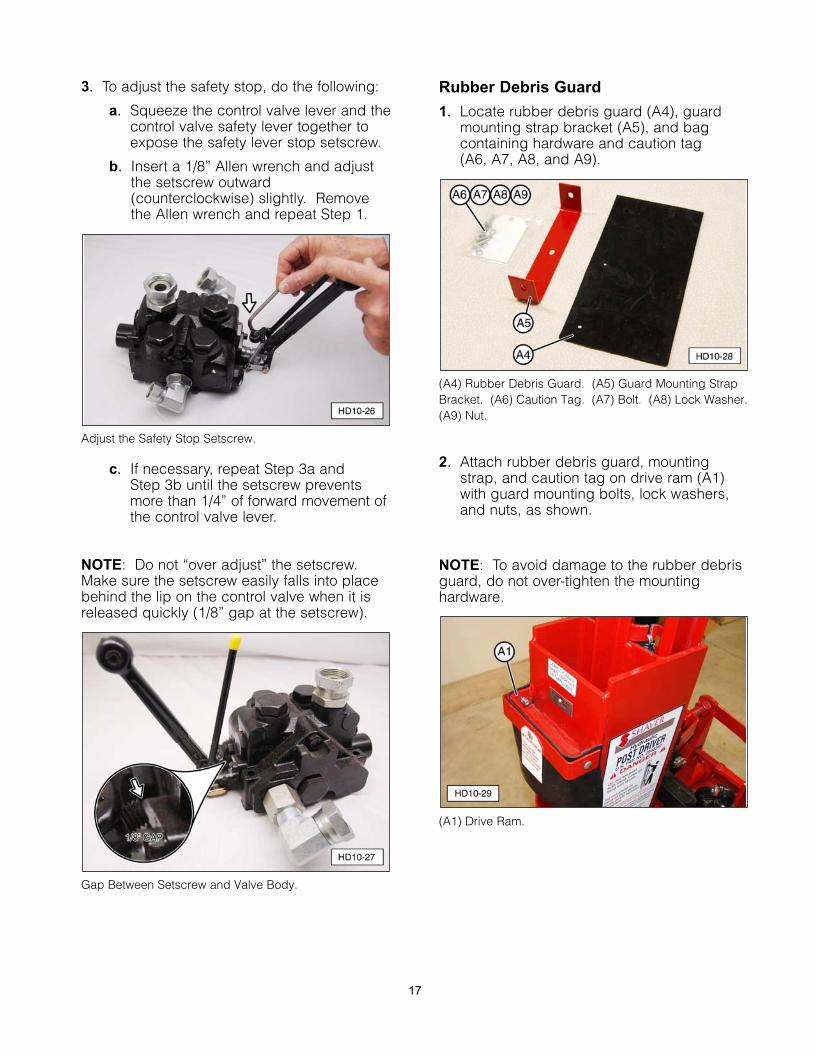
3. To adjust the safety stop, do the following:
a. Squeeze the control valve lever and thecontrol valve safety lever together toexpose the safety lever stop setscrew.
b. Insert a 1/8” Allen wrench and adjustthe setscrew outward(counterclockwise) slightly. Removethe Allen wrench and repeat Step 1.
Adjust the Safety Stop Setscrew.
c. If necessary, repeat Step 3a and Step 3b until the setscrew preventsmore than 1/4” of forward movement ofthe control valve lever.
NOTE: Do not “over adjust” the setscrew.Make sure the setscrew easily falls into placebehind the lip on the control valve when it isreleased quickly (1/8” gap at the setscrew).
Gap Between Setscrew and Valve Body.
Rubber Debris Guard
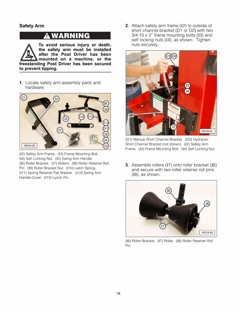
1. Locate rubber debris guard (A4), guardmounting strap bracket (A5), and bagcontaining hardware and caution tag (A6, A7, A8, and A9).
(A4) Rubber Debris Guard. (A5) Guard Mounting StrapBracket. (A6) Caution Tag. (A7) Bolt. (A8) Lock Washer. (A9) Nut.
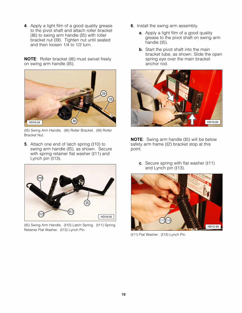
2. Attach rubber debris guard, mountingstrap, and caution tag on drive ram (A1)with guard mounting bolts, lock washers,and nuts, as shown.
NOTE: To avoid damage to the rubber debrisguard, do not over-tighten the mountinghardware.
(A1) Drive Ram.
Safety Arm
To avoid serious injury or death,the safety arm must be installedafter the Post Driver has beenmounted on a machine, or the
freestanding Post Driver has been securedto prevent tipping.
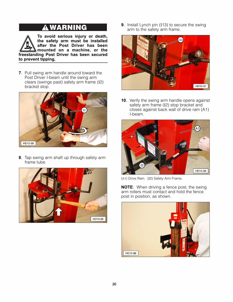
1. Locate safety arm assembly parts andhardware.
(I2) Safety Arm Frame. (I3) Frame Mounting Bolt. (I4) Self Locking Nut. (I5) Swing Arm Handle. (I6) Roller Bracket. (I7) Rollers. (I8) Roller Retainer RollPin. (I9) Roller Bracket Nut. (I10) Latch Spring. (I11) Spring Retainer Flat Washer. (I12) Swing ArmHandle Cover. (I13) Lynch Pin.
2. Attach safety arm frame (I2) to outside ofshort channel bracket (D1 or D2) with two 3/4-10 x 2” frame mounting bolts (I3) andself locking nuts (I4), as shown. Tightennuts securely.
(D1) Manual Short Channel Bracket. (D2) HydraulicShort Channel Bracket (not shown). (I2) Safety ArmFrame. (I3) Frame Mounting Bolt. (I4) Self Locking Nut.
3. Assemble rollers (I7) onto roller bracket (I6)and secure with two roller retainer roll pins(I8), as shown.
(I6) Roller Bracket. (I7) Roller. (I8) Roller Retainer RollPin.
WARNING
18
19
4. Apply a light film of a good quality greaseto the pivot shaft and attach roller bracket(I6) to swing arm handle (I5) with rollerbracket nut (I9). Tighten nut until seatedand then loosen 1/4 to 1/2 turn.
NOTE: Roller bracket (I6) must swivel freelyon swing arm handle (I5).
(I5) Swing Arm Handle. (I6) Roller Bracket. (I9) RollerBracket Nut.
5. Attach one end of latch spring (I10) toswing arm handle (I5), as shown. Securewith spring retainer flat washer (I11) andLynch pin (I13).
(I5) Swing Arm Handle. (I10) Latch Spring. (I11) SpringRetainer Flat Washer. (I13) Lynch Pin.
6. Install the swing arm assembly.
a. Apply a light film of a good qualitygrease to the pivot shaft on swing armhandle (I5).
b. Start the pivot shaft into the mainbracket tube, as shown. Slide the openspring eye over the main bracketanchor rod.
NOTE: Swing arm handle (I5) will be belowsafety arm frame (I2) bracket stop at thispoint.
c. Secure spring with flat washer (I11)and Lynch pin (I13).
(I11) Flat Washer. (I13) Lynch Pin.
19
To avoid serious injury or death,the safety arm must be installedafter the Post Driver has beenmounted on a machine, or the
freestanding Post Driver has been securedto prevent tipping.
7. Pull swing arm handle around toward thePost Driver I-beam until the swing armclears (swings past) safety arm frame (I2)bracket stop.
8. Tap swing arm shaft up through safety armframe tube.
9. Install Lynch pin (I13) to secure the swingarm to the safety arm frame.
10. Verify the swing arm handle opens againstsafety arm frame (I2) stop bracket andcloses against back wall of drive ram (A1)I-beam.
(A1) Drive Ram. (I2) Safety Arm Frame.
NOTE: When driving a fence post, the swingarm rollers must contact and hold the fencepost in position, as shown.
WARNING
2020
Document Storage Tube
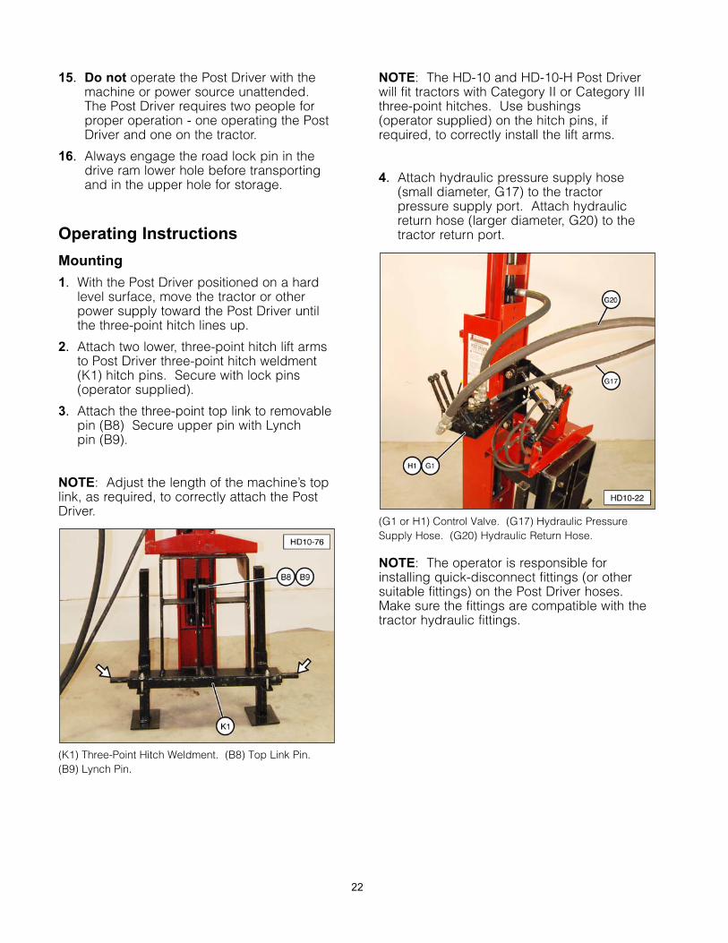
1. If desired, locate the document storagetube in a convenient location on the PostDriver. The photo below shows the tubemounted on the drive ram, but otherlocations are acceptable.
2. Mark the location of the two mounting holesusing the storage tube as a guide.
3. Drill two 3/16” holes.
4. Attach the storage tube with the two poprivets supplied inside the tube.
Post Driver Operation
Operational Safety Tips
1. Follow all safety information contained inthis manual and refer to safety decalslocated on the Post Driver.
2. Personal safety equipment must be worn atall times during operation, i.e. safetyglasses, steel toe shoes, hearingprotection, etc.
3. Always stand 45 degrees to the right of thepost while the Post Driver is in operation.
4. Do not remove any of the Post Driversafety equipment or safety labels.
5. All Post Driver safety equipment must beinspected, maintained, kept in workingorder, and used during Post Driveroperation.
6. Do not place your hand(s) on top of thepost when placing the post in the PostDriver or while the Post Driver is operating.
7. Leave the safety arm attachment openwhen not holding a post, except whentransporting the Post Driver.
8. Do not remove the hydraulic control valvesafety lever stop.
9. Never use the maximum force of the PostDriver until the post being driven is startedinto the ground and is straight.
10. Use caution when driving small diameterwood or steel posts. Maximum drivingimpact is not necessary.
11. Always be aware of the environment inwhich you are operating the Post Driver.
12. Do not operate the Post Driver on steepslopes, as this could cause a roll over.
13. Always check for underground utilities, i.e.wires, gas lines, waterlines, etc. Call yourlocal utility companies for undergroundutility locations.
14. Use caution where large rocks or otherobjects could be hidden underground andnot visible to the operator. The post couldsplinter and cause injury to the operator.If the post fails to drive into the groundafter two or three strikes, move to anotherlocation.
21
15. Do not operate the Post Driver with themachine or power source unattended.The Post Driver requires two people forproper operation - one operating the PostDriver and one on the tractor.
16. Always engage the road lock pin in thedrive ram lower hole before transportingand in the upper hole for storage.
Operating Instructions
Mounting
1. With the Post Driver positioned on a hardlevel surface, move the tractor or otherpower supply toward the Post Driver untilthe three-point hitch lines up.
2. Attach two lower, three-point hitch lift armsto Post Driver three-point hitch weldment(K1) hitch pins. Secure with lock pins(operator supplied).
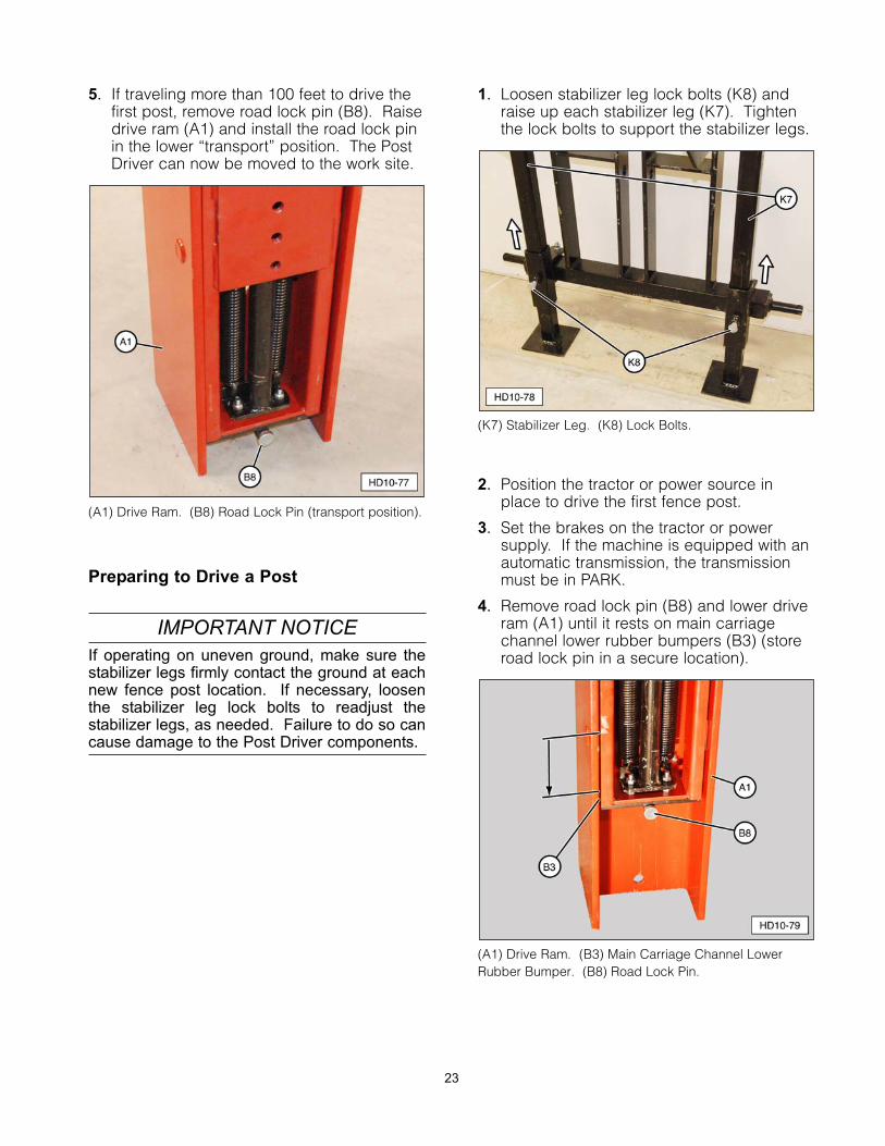
3. Attach the three-point top link to removablepin (B8) Secure upper pin with Lynch pin (B9).
NOTE: Adjust the length of the machine’s toplink, as required, to correctly attach the PostDriver.
(K1) Three-Point Hitch Weldment. (B8) Top Link Pin. (B9) Lynch Pin.
NOTE: The HD-10 and HD-10-H Post Driverwill fit tractors with Category II or Category IIIthree-point hitches. Use bushings (operator supplied) on the hitch pins, ifrequired, to correctly install the lift arms.
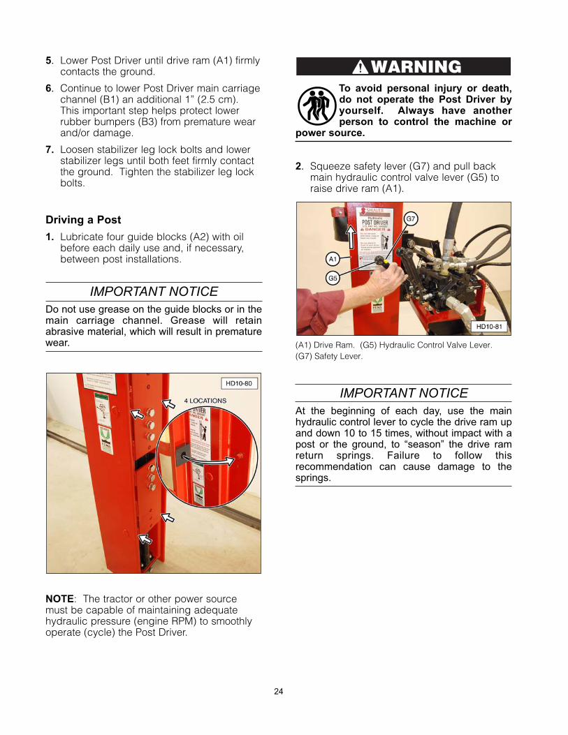
4. Attach hydraulic pressure supply hose(small diameter, G17) to the tractorpressure supply port. Attach hydraulicreturn hose (larger diameter, G20) to thetractor return port.
(G1 or H1) Control Valve. (G17) Hydraulic PressureSupply Hose. (G20) Hydraulic Return Hose.
NOTE: The operator is responsible forinstalling quick-disconnect fittings (or othersuitable fittings) on the Post Driver hoses.Make sure the fittings are compatible with thetractor hydraulic fittings.
22
5. If traveling more than 100 feet to drive thefirst post, remove road lock pin (B8). Raisedrive ram (A1) and install the road lock pinin the lower “transport” position. The PostDriver can now be moved to the work site.
(A1) Drive Ram. (B8) Road Lock Pin (transport position).
Preparing to Drive a Post
IMPORTANT NOTICEIf operating on uneven ground, make sure thestabilizer legs firmly contact the ground at eachnew fence post location. If necessary, loosenthe stabilizer leg lock bolts to readjust thestabilizer legs, as needed. Failure to do so cancause damage to the Post Driver components.
1. Loosen stabilizer leg lock bolts (K8) andraise up each stabilizer leg (K7). Tightenthe lock bolts to support the stabilizer legs.
(K7) Stabilizer Leg. (K8) Lock Bolts.
2. Position the tractor or power source inplace to drive the first fence post.
3. Set the brakes on the tractor or powersupply. If the machine is equipped with anautomatic transmission, the transmissionmust be in PARK.
4. Remove road lock pin (B8) and lower driveram (A1) until it rests on main carriagechannel lower rubber bumpers (B3) (storeroad lock pin in a secure location).
(A1) Drive Ram. (B3) Main Carriage Channel LowerRubber Bumper. (B8) Road Lock Pin.
23
5. Lower Post Driver until drive ram (A1) firmlycontacts the ground.
6. Continue to lower Post Driver main carriagechannel (B1) an additional 1” (2.5 cm).This important step helps protect lowerrubber bumpers (B3) from premature wearand/or damage.
7. Loosen stabilizer leg lock bolts and lowerstabilizer legs until both feet firmly contactthe ground. Tighten the stabilizer leg lockbolts.
Driving a Post
1. Lubricate four guide blocks (A2) with oilbefore each daily use and, if necessary,between post installations.
IMPORTANT NOTICEDo not use grease on the guide blocks or in themain carriage channel. Grease will retainabrasive material, which will result in prematurewear.
NOTE: The tractor or other power sourcemust be capable of maintaining adequatehydraulic pressure (engine RPM) to smoothlyoperate (cycle) the Post Driver.
To avoid personal injury or death,do not operate the Post Driver byyourself. Always have anotherperson to control the machine or
power source.
2. Squeeze safety lever (G7) and pull backmain hydraulic control valve lever (G5) toraise drive ram (A1).
(A1) Drive Ram. (G5) Hydraulic Control Valve Lever. (G7) Safety Lever.
IMPORTANT NOTICEAt the beginning of each day, use the mainhydraulic control lever to cycle the drive ram upand down 10 to 15 times, without impact with apost or the ground, to “season” the drive ramreturn springs. Failure to follow thisrecommendation can cause damage to thesprings.
WARNING
24
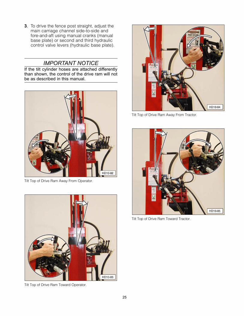
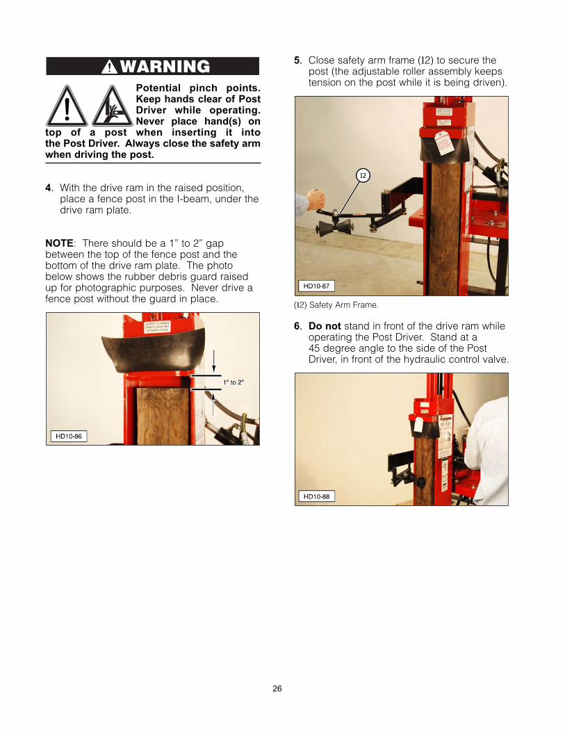
3. To drive the fence post straight, adjust themain carriage channel side-to-side andfore-and-aft using manual cranks (manualbase plate) or second and third hydrauliccontrol valve levers (hydraulic base plate).
IMPORTANT NOTICEIf the tilt cylinder hoses are attached differentlythan shown, the control of the drive ram will notbe as described in this manual.
Tilt Top of Drive Ram Away From Operator.
Tilt Top of Drive Ram Toward Operator.
Tilt Top of Drive Ram Away From Tractor.
Tilt Top of Drive Ram Toward Tractor.
25
Potential pinch points.Keep hands clear of PostDriver while operating. Never place hand(s) on
top of a post when inserting it into the Post Driver. Always close the safety armwhen driving the post.
4. With the drive ram in the raised position,place a fence post in the I-beam, under thedrive ram plate.
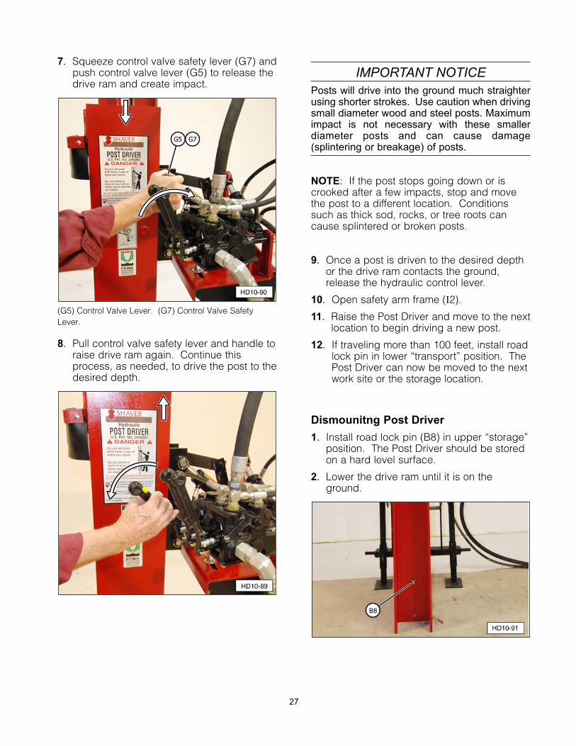
NOTE: There should be a 1” to 2” gapbetween the top of the fence post and thebottom of the drive ram plate. The photobelow shows the rubber debris guard raisedup for photographic purposes. Never drive afence post without the guard in place.
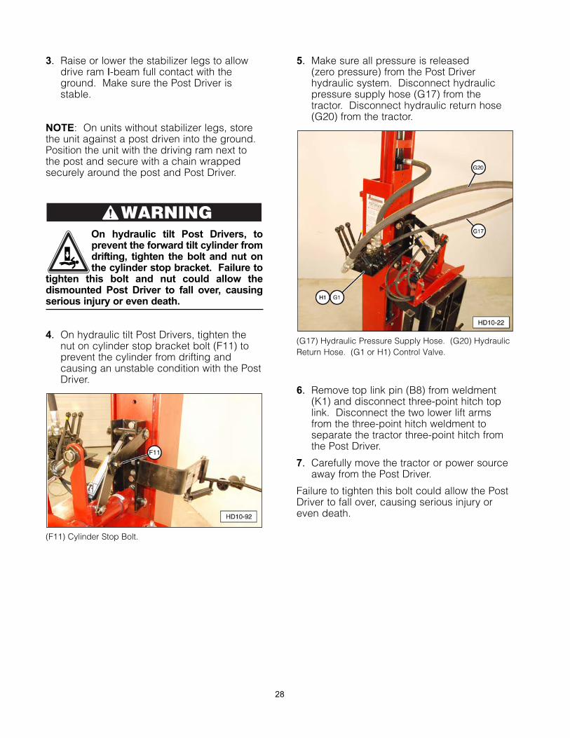
5. Close safety arm frame (I2) to secure thepost (the adjustable roller assembly keepstension on the post while it is being driven).
(I2) Safety Arm Frame.
6. Do not stand in front of the drive ram whileoperating the Post Driver. Stand at a 45 degree angle to the side of the PostDriver, in front of the hydraulic control valve.
WARNING
26
7. Squeeze control valve safety lever (G7) andpush control valve lever (G5) to release thedrive ram and create impact.
(G5) Control Valve Lever. (G7) Control Valve SafetyLever.
8. Pull control valve safety lever and handle toraise drive ram again. Continue thisprocess, as needed, to drive the post to thedesired depth.
IMPORTANT NOTICEPosts will drive into the ground much straighterusing shorter strokes. Use caution when drivingsmall diameter wood and steel posts. Maximumimpact is not necessary with these smallerdiameter posts and can cause damage(splintering or breakage) of posts.
NOTE: If the post stops going down or iscrooked after a few impacts, stop and movethe post to a different location. Conditionssuch as thick sod, rocks, or tree roots cancause splintered or broken posts.
9. Once a post is driven to the desired depthor the drive ram contacts the ground,release the hydraulic control lever.
10. Open safety arm frame (I2).
11. Raise the Post Driver and move to the nextlocation to begin driving a new post.
12. If traveling more than 100 feet, install roadlock pin in lower “transport” position. ThePost Driver can now be moved to the nextwork site or the storage location.
Dismounitng Post Driver
1. Install road lock pin (B8) in upper “storage”position. The Post Driver should be storedon a hard level surface.
2. Lower the drive ram until it is on theground.
27
3. Raise or lower the stabilizer legs to allowdrive ram I-beam full contact with theground. Make sure the Post Driver isstable.
NOTE: On units without stabilizer legs, storethe unit against a post driven into the ground.Position the unit with the driving ram next tothe post and secure with a chain wrappedsecurely around the post and Post Driver.
On hydraulic tilt Post Drivers, toprevent the forward tilt cylinder fromdrifting, tighten the bolt and nut onthe cylinder stop bracket. Failure to
tighten this bolt and nut could allow thedismounted Post Driver to fall over, causingserious injury or even death.
4. On hydraulic tilt Post Drivers, tighten thenut on cylinder stop bracket bolt (F11) toprevent the cylinder from drifting andcausing an unstable condition with the PostDriver.
(F11) Cylinder Stop Bolt.
5. Make sure all pressure is released (zero pressure) from the Post Driverhydraulic system. Disconnect hydraulicpressure supply hose (G17) from thetractor. Disconnect hydraulic return hose(G20) from the tractor.
(G17) Hydraulic Pressure Supply Hose. (G20) HydraulicReturn Hose. (G1 or H1) Control Valve.
6. Remove top link pin (B8) from weldment(K1) and disconnect three-point hitch toplink. Disconnect the two lower lift armsfrom the three-point hitch weldment toseparate the tractor three-point hitch fromthe Post Driver.
7. Carefully move the tractor or power sourceaway from the Post Driver.
Failure to tighten this bolt could allow the PostDriver to fall over, causing serious injury oreven death.
WARNING
28
Troubleshooting
NOTE: Refer to the Service Parts section ofthis manual for a photo and description of allthe parts.
Problem: Drive ram (A1) will not move orslide freely on main carriagechannel (B1).
Possible Cause/Solution(s):
1. Guide blocks (A2) lack lubricant. Lubricatewith clean engine oil.
2. Guide blocks (A2) installed incorrectly.Refer to Service Information sectionassembly procedures for correctorientation.
3. Incorrect clearance between main carriagechannel (B1) and drive ram (A1) I-beam.Refer to Service Information section forclearance specifications.
4. Hydraulic drive cylinder assembly (C1) isnot parallel to main carriage channel (B1).Refer to Service Information section,hydraulic drive cylinder installation, andparallelism adjustment.
5. Main carriage channel (B1) or drive ram(A1) is bent or damaged. Discontinue useand order replacement parts.
Problem: Poor performance, low or noimpact, hydraulic drive cylinder willnot extend.
Possible Cause/Solution(s):
1. Weak or broken drive ram springs (C14).
2. Broken lower spring bracket (C13).
3. Bent or damaged hydraulic drive cylinderassembly (C1).
4. Main carriage channel (B1) is binding.
5. Restricted or plugged hydraulic hose(s)(G15, G17, G20).
6. Low or no hydraulic pressure or flow fromthe machine or power source.
Problem: Rubber bumpers (B3) havepremature or excessive damage.
Possible Cause/Solution(s):
1. Post Driver is not properly adjusted prior tooperation and drive ram guide blocks (A2)are contacting rubber bumpers (B3).
StorageFor best results, always store equipment in adry, protected location. Leaving equipmentunprotected will shorten the service life of theimplement.
1. Before storing, remove debris and cleanthe entire unit with compressed air orpressure washer.
2. Inspect the Shaver Post Driver. Replaceany worn or damaged parts before usingthe Post Driver again.
• Check all bolted connections. Ensurethat fasteners are tight, and all pins aresecured in place.
• Inspect frame for structural fractures.
• Make sure all warning decals are in placeand legible.
• Make sure rubber debris guard is in placeand in good condition.
• Check hydraulic cylinder(s) for signs ofseal damage or excessive wear.
• Inspect all hydraulic hoses and fittings forleaks or signs of wear.
3. After cleaning, lightly lubricate guideblocks with clean engine oil. Do not applygrease, as this will retain grit and causeexcessive wear.
4. Clean and lubricate hydraulic control valvesafety stop linkage. Make sure returnspring and cotter pins are in goodcondition.
5. Apply a light coating of clean grease to allexposed hydraulic cylinder shafts to helpprevent rust.
29
Service Procedures
To avoid personal injury or death,carefully read and understand allinstructions before attempting toassemble and/or operate the Post
Driver. Do not operate or work on equipmentunless you read and understand theinstructions and warnings in this and allother applicable manuals. Contact ShaverManufacturing Company if any of theinstructions provided are unclear or notunderstood. Proper care is yourresponsibility. Always follow all State andFederal health and safety laws and/or localregulations.
To help prevent personalinjury, protectiveequipment must be wornduring Post Driverassembly, operation, andmaintenance. Personalprotective equipmentshould include, but not
be limited to, safety glasses, hearingprotection, protective gloves, and steel toefootwear.
Before making anyadjustments on the PostDriver, ensure that allhydraulic levers are in the
neutral position. Always shut off themachine, set parking brake, and remove keybefore performing any service.
Personal injury can resultfrom slips or falls. DONOT leave tools or partslaying around the work
area, and clean up all spilled fluidsimmediately.
NOTE: Disassembly, assembly, and/orassociated repairs must be performed with themain carriage channel and drive ram in ahorizontal position, such as on a suitablepallet, or heavy-duty support stands.
Refer to Dismounting Post Driver fromMachine/Power Source section for steps toremove Post Driver from a tractor or otherpower source.
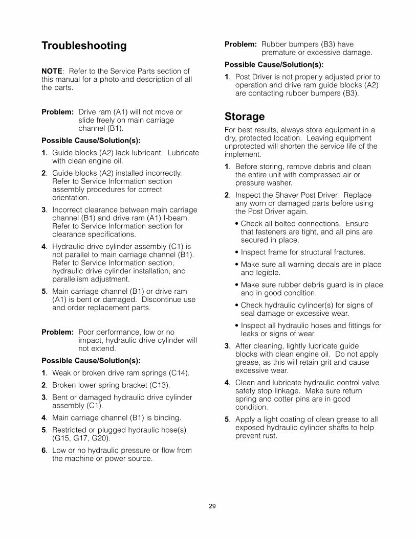
Three-Point Hitch/Post Driver
Disassembly
1. Secure the Post Driver upright [maincarriage channel (B1) and drive ram (A1)assembly] to an appropriate overheadlifting device to prevent tipping.
2. Disconnect drive cylinder to valve hose(G15) and drain fluid into a suitablecontainer.
3. On hydraulic base plate Post Drivers,tighten cylinder stop bolt (F11). Disconnectfour tilt cylinder hoses (H5) from hydrauliccontrol valve (H1), and drain fluid into asuitable container.
4. Remove Lynch pins (D7) and two channelmounting pins (D6) that connect the baseplate to the Post Driver upright (applies tomanual or hydraulic models).
NOTE: If necessary, lubricate channelmounting pins with penetrating oil to assist pinremoval.
5. With assistance, carefully move the three-point hitch weldment/base plate assemblyaway from the Post Driver upright. Storeweldment/base plate assembly in a safelocation.
6. The upright assembly is heavy. Use anappropriate lifting device to position thePost Driver assembly horizontally, onsuitable stands, pallet, or blocks on theground.
WARNING
30
Main Carriage Channel
Disassembly
NOTE: Be prepared to collect any hydraulicfluid that drains from the cylinder into asuitable container.
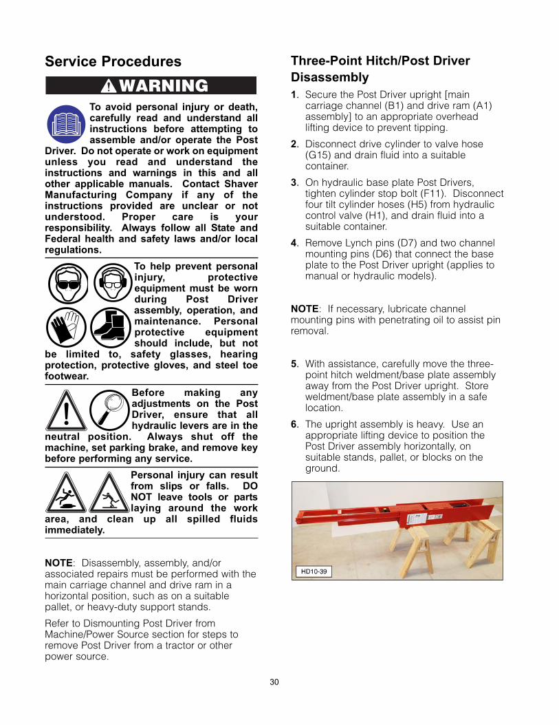
1a. Remove road lock pin (B8).
1b. Slide the main carriage channel up as faras possible, to relieve tension on thesprings.
(B8) Road Lock Pin.
2. Loosen, but do not remove,, twoself-locking nuts (C12) that attach drivecylinder (C2) and lower spring bracket(C13) to main carriage channel (B1).
(B1) Main Carriage Channel. (C1) Drive Cylinder. (C12) Self-Locking Nut. (C13) Lower Spring Bracket.
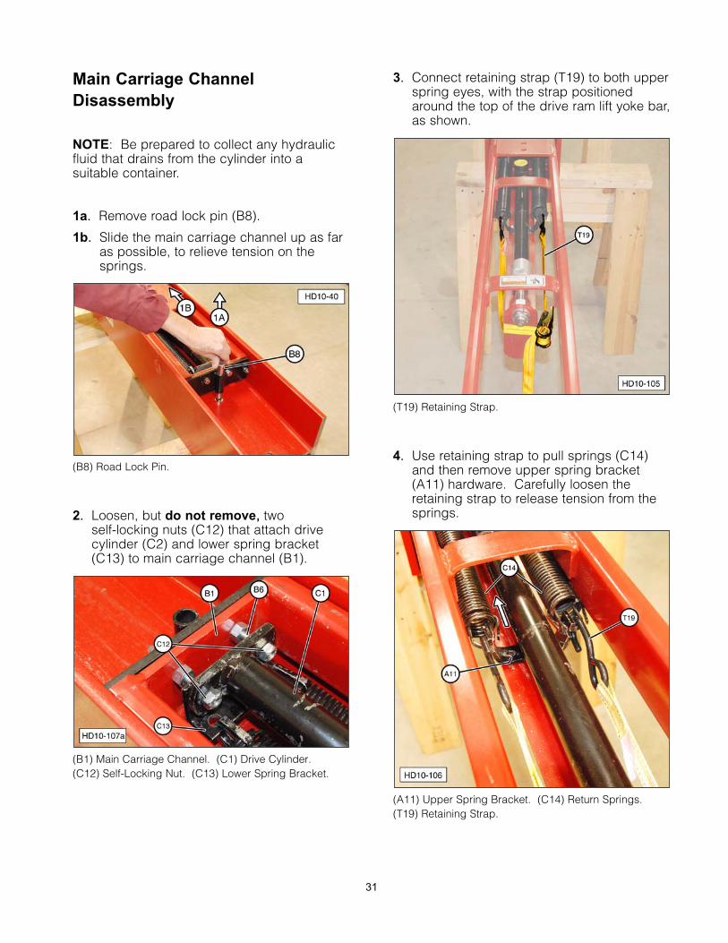
3. Connect retaining strap (T19) to both upperspring eyes, with the strap positionedaround the top of the drive ram lift yoke bar,as shown.
(T19) Retaining Strap.
4. Use retaining strap to pull springs (C14)and then remove upper spring bracket(A11) hardware. Carefully loosen theretaining strap to release tension from thesprings.
(A11) Upper Spring Bracket. (C14) Return Springs.(T19) Retaining Strap.
31
32
5. Remove the retaining strap and the upperspring bracket.
6. Remove upper cylinder rod self-locking nut(C4) and lock washer (C16) from drivecylinder piston (C3).
NOTE: Do not reuse self-locking nut (C4).Replace with a new self-locking nut.
(C3) Drive Cylinder Piston. (C4) Self-Locking Nut. (C16) Lock Washer.
7. Remove two self-locking nuts (C12) whichwere loosened in Step 2. Remove drivecylinder (C1) and lower spring bracket(C13) from road lock bracket bolts (B6)
8. Remove two road lock bracket nuts (B7)and remove road lock bracket (B2) frommain carriage channel (B1).
(B1) Main Carriage Channel. (B2) Road Lock Bracket.(B7) Road Lock Bracket Nuts.
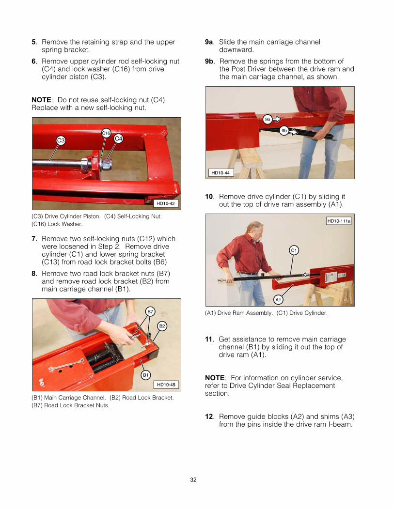
9a. Slide the main carriage channeldownward.
9b. Remove the springs from the bottom ofthe Post Driver between the drive ram andthe main carriage channel, as shown.
10. Remove drive cylinder (C1) by sliding itout the top of drive ram assembly (A1).
(A1) Drive Ram Assembly. (C1) Drive Cylinder.
11. Get assistance to remove main carriagechannel (B1) by sliding it out the top ofdrive ram (A1).
NOTE: For information on cylinder service,refer to Drive Cylinder Seal Replacementsection.
12. Remove guide blocks (A2) and shims (A3)from the pins inside the drive ram I-beam.
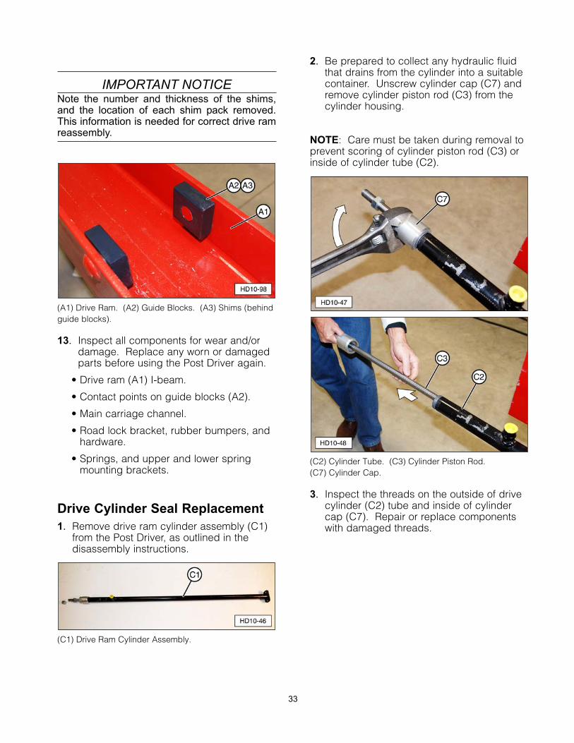
IMPORTANT NOTICENote the number and thickness of the shims,and the location of each shim pack removed.This information is needed for correct drive ramreassembly.
(A1) Drive Ram. (A2) Guide Blocks. (A3) Shims (behindguide blocks).
13. Inspect all components for wear and/ordamage. Replace any worn or damagedparts before using the Post Driver again.
• Drive ram (A1) I-beam.
• Contact points on guide blocks (A2).
• Main carriage channel.
• Road lock bracket, rubber bumpers, andhardware.
• Springs, and upper and lower springmounting brackets.
Drive Cylinder Seal Replacement
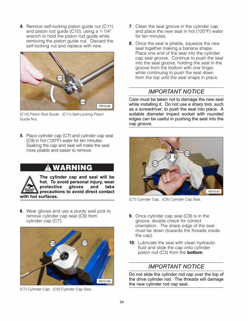
1. Remove drive ram cylinder assembly (C1)from the Post Driver, as outlined in thedisassembly instructions.
(C1) Drive Ram Cylinder Assembly.
2. Be prepared to collect any hydraulic fluidthat drains from the cylinder into a suitablecontainer. Unscrew cylinder cap (C7) andremove cylinder piston rod (C3) from thecylinder housing.
NOTE: Care must be taken during removal toprevent scoring of cylinder piston rod (C3) orinside of cylinder tube (C2).
(C2) Cylinder Tube. (C3) Cylinder Piston Rod. (C7) Cylinder Cap.
3. Inspect the threads on the outside of drivecylinder (C2) tube and inside of cylindercap (C7). Repair or replace componentswith damaged threads.
33
4. Remove self-locking piston guide nut (C11)and piston rod guide (C10), using a 1-1/4”wrench to hold the piston rod guide whileremoving the piston guide nut. Discard theself-locking nut and replace with new.
(C10) Piston Rod Guide. (C11) Self-Locking PistonGuide Nut.
5. Place cylinder cap (C7) and cylinder cap seal(C9) in hot (120°F) water for ten minutes.Soaking the cap and seal will make the sealmore pliable and easier to remove.
The cylinder cap and seal will behot. To avoid personal injury, wearprotective gloves and takeprecautions to avoid direct contact
with hot surfaces.
6. Wear gloves and use a sturdy seal pick toremove cylinder cap seal (C9) fromcylinder cap (C7).
(C7) Cylinder Cap. (C9) Cylinder Cap Seal.
7. Clean the seal groove in the cylinder capand place the new seal in hot (120°F) waterfor ten minutes.
8. Once the seal is pliable, squeeze the newseal together making a banana shape.Place one end of the seal into the cylindercap seal groove. Continue to push the sealinto the seal groove, holding the seal in thegroove from the bottom with one finger,while continuing to push the seal downfrom the top until the seal snaps in place.
IMPORTANT NOTICECare must be taken not to damage the new sealwhile installing it. Do not use a sharp tool, suchas a screwdriver, to push the seal into place. Asuitable diameter impact socket with roundededges can be useful in pushing the seal into thecap groove.
(C7) Cylinder Cap. (C9) Cylinder Cap Seal.
9. Once cylinder cap seal (C9) is in thegroove, double check for correctorientation. The sharp edge of the sealmust be down (towards the threads insidethe cap).
10. Lubricate the seal with clean hydraulicfluid and slide the cap onto cylinderpiston rod (C3) from the bottom.
IMPORTANT NOTICEDo not slide the cylinder rod cap over the top ofthe drive cylinder rod. The threads will damagethe new cylinder rod cap seal.
WARNING
34
11. Install piston guide (C10) and newself-locking piston guide nut (C11), usinga 1-1/4” wrench to hold the piston guidewhile installing the piston guide nut. Donot over-tighten the self-locking nut.Piston guide (C10) must be able to rotateon cylinder piston rod (C3).
12. Install cylinder piston rod (C3) assemblyinto drive cylinder tube (C2).
NOTE: Care must be taken during installationto prevent scoring of cylinder piston rod (C3) orthe inside of drive ram cylinder tube (C2).
13. Apply paste-type thread sealant (T12) ondrive cylinder tube (C2) external threadsand install cylinder cap assembly (C7).Tighten cap securely.
IMPORTANT NOTICEHydraulic system fittings that require a threadsealant must be installed with a paste-typesealer only. Do not use a tape-type sealer, suchas Teflon Tape, as this can contaminate thesystem and voids the valve warranty.
14. To install drive cylinder assembly (C1) inthe Post Driver, follow the instructions inthe Main Carriage Channel Assemblysection.
Main Carriage Channel Assembly
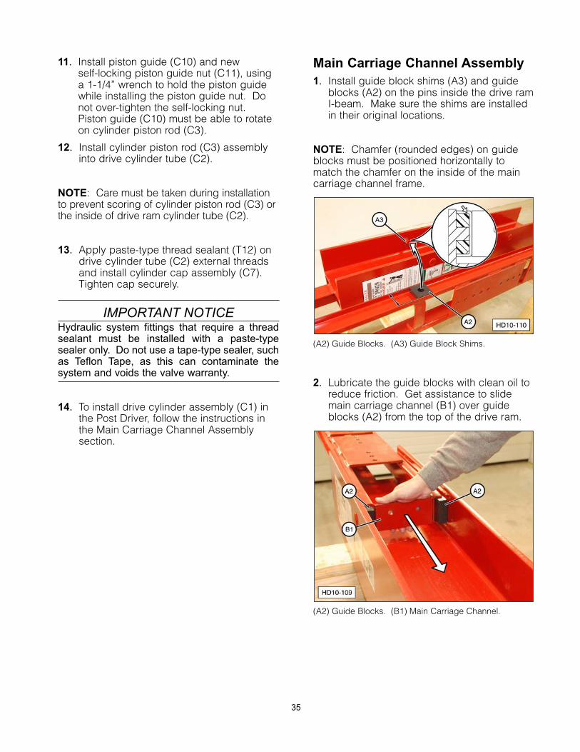
1. Install guide block shims (A3) and guideblocks (A2) on the pins inside the drive ramI-beam. Make sure the shims are installedin their original locations.
NOTE: Chamfer (rounded edges) on guideblocks must be positioned horizontally tomatch the chamfer on the inside of the maincarriage channel frame.
(A2) Guide Blocks. (A3) Guide Block Shims.
2. Lubricate the guide blocks with clean oil toreduce friction. Get assistance to slidemain carriage channel (B1) over guideblocks (A2) from the top of the drive ram.
(A2) Guide Blocks. (B1) Main Carriage Channel.
35
3. The main carriage channel should slideback and forth freely.
4. With the drive ram assembly horizontal,check the up and down movement of themain carriage channel in the drive ramI-beam. Up and down movement shouldnot be less than 1/4” or more than 1/2”.
5. Install drive cylinder (C1) in drive ramassembly (A1) from the top (upper end).
(A1) Drive Ram. (C1) Drive Cylinder.
NOTE: Hydraulic drive ram cylinder (C1) mustbe inserted in main carriage channel (B1)before springs (C14) are inserted. Position thecylinder laying loose inside the main carriagechannel.
6. Install springs (C14) from the bottom of thePost Driver between drive ram (A1) I-beamand main carriage channel (B1), and slideinto position.
(A1) Drive Ram. (B1) Main Carriage Channel. (C14) Springs.
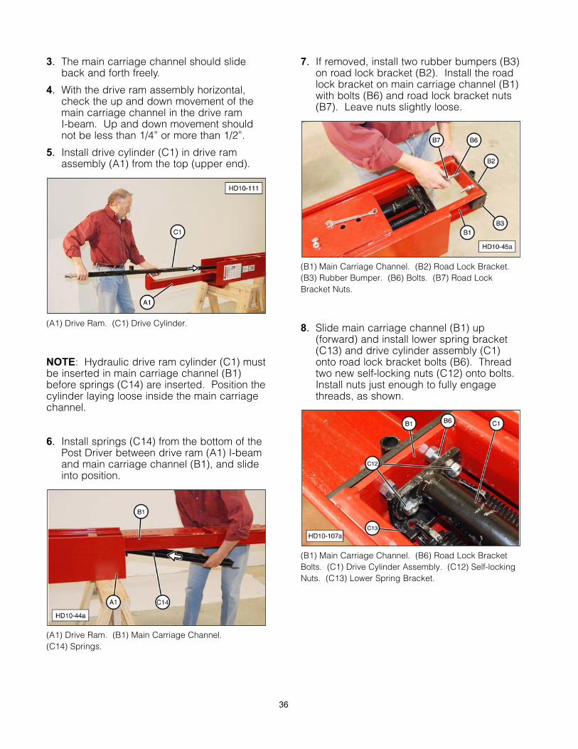
7. If removed, install two rubber bumpers (B3)on road lock bracket (B2). Install the roadlock bracket on main carriage channel (B1)with bolts (B6) and road lock bracket nuts(B7). Leave nuts slightly loose.
(B1) Main Carriage Channel. (B2) Road Lock Bracket.(B3) Rubber Bumper. (B6) Bolts. (B7) Road LockBracket Nuts.
8. Slide main carriage channel (B1) up(forward) and install lower spring bracket(C13) and drive cylinder assembly (C1)onto road lock bracket bolts (B6). Threadtwo new self-locking nuts (C12) onto bolts.Install nuts just enough to fully engagethreads, as shown.
(B1) Main Carriage Channel. (B6) Road Lock BracketBolts. (C1) Drive Cylinder Assembly. (C12) Self-lockingNuts. (C13) Lower Spring Bracket.
36
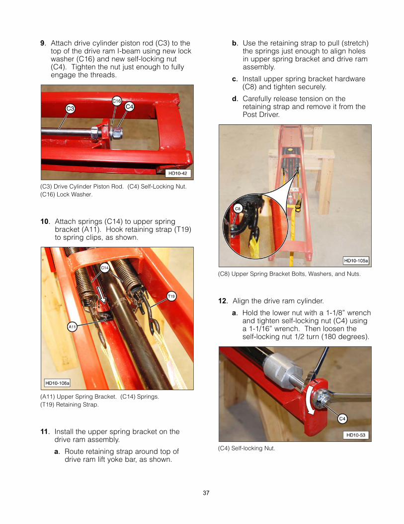
9. Attach drive cylinder piston rod (C3) to thetop of the drive ram I-beam using new lockwasher (C16) and new self-locking nut(C4). Tighten the nut just enough to fullyengage the threads.
(C3) Drive Cylinder Piston Rod. (C4) Self-Locking Nut.(C16) Lock Washer.
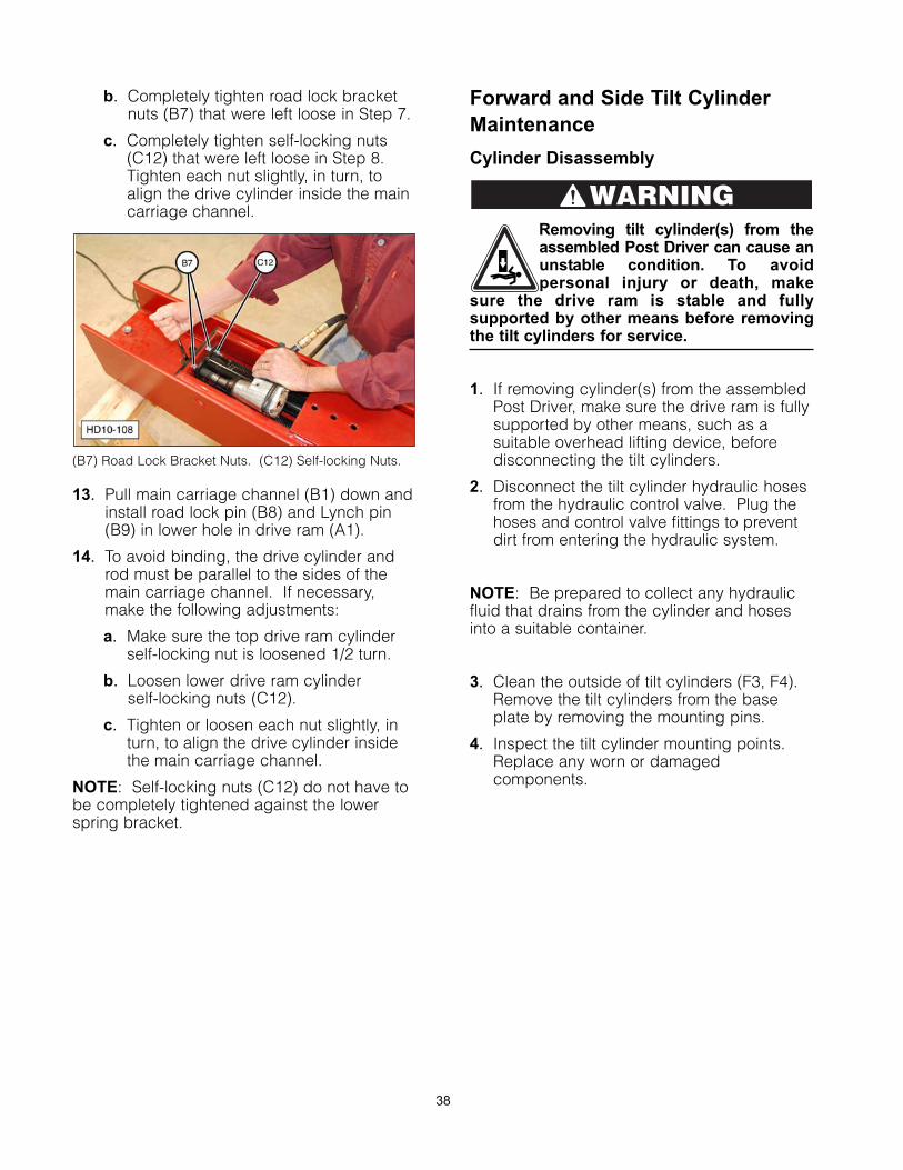
10. Attach springs (C14) to upper springbracket (A11). Hook retaining strap (T19)to spring clips, as shown.
(A11) Upper Spring Bracket. (C14) Springs. (T19) Retaining Strap.
11. Install the upper spring bracket on thedrive ram assembly.
a. Route retaining strap around top ofdrive ram lift yoke bar, as shown.
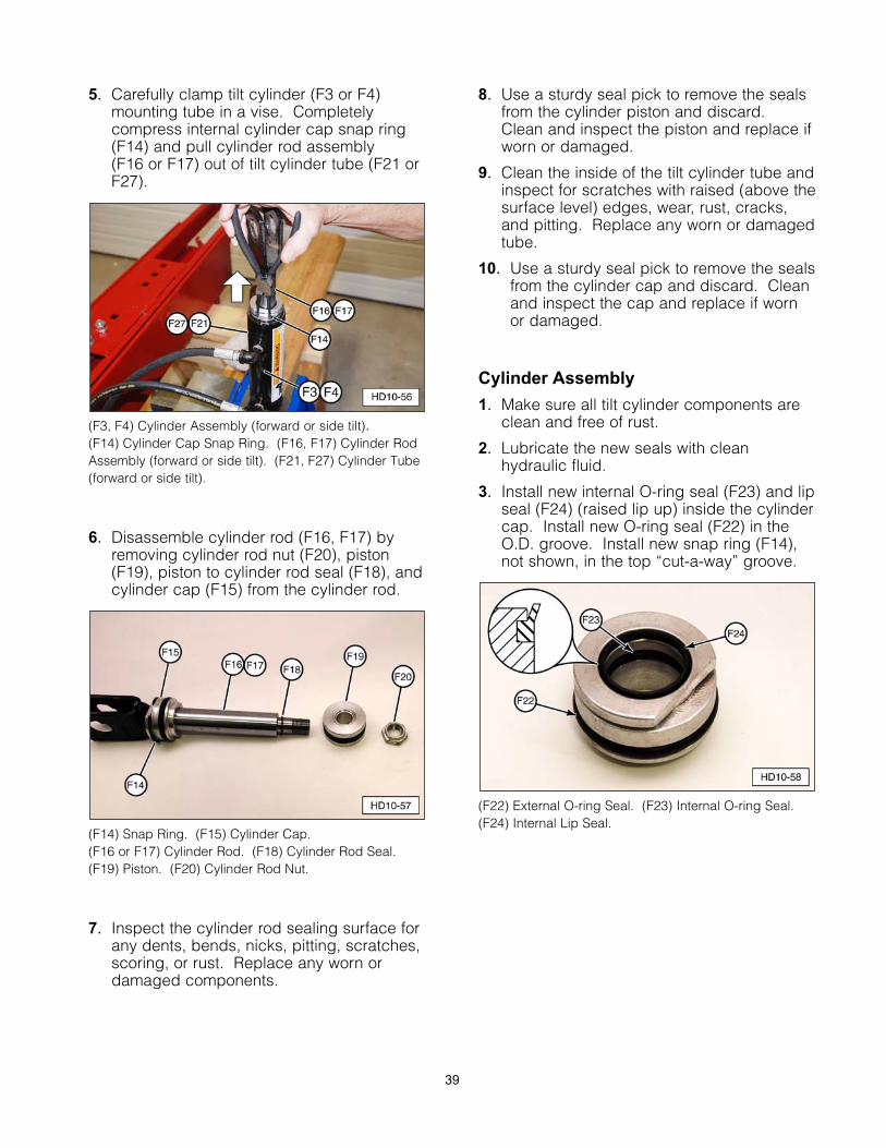
b. Use the retaining strap to pull (stretch)the springs just enough to align holesin upper spring bracket and drive ramassembly.
c. Install upper spring bracket hardware(C8) and tighten securely.
d. Carefully release tension on theretaining strap and remove it from thePost Driver.
(C8) Upper Spring Bracket Bolts, Washers, and Nuts.
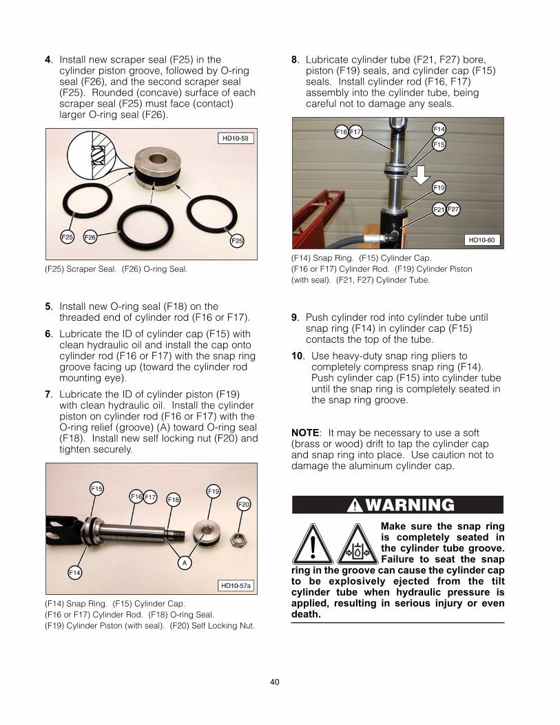
12. Align the drive ram cylinder.
a. Hold the lower nut with a 1-1/8” wrenchand tighten self-locking nut (C4) usinga 1-1/16” wrench. Then loosen theself-locking nut 1/2 turn (180 degrees).
(C4) Self-locking Nut.
37
b. Completely tighten road lock bracketnuts (B7) that were left loose in Step 7.
c. Completely tighten self-locking nuts(C12) that were left loose in Step 8.Tighten each nut slightly, in turn, toalign the drive cylinder inside the maincarriage channel.
(B7) Road Lock Bracket Nuts. (C12) Self-locking Nuts.
13. Pull main carriage channel (B1) down andinstall road lock pin (B8) and Lynch pin(B9) in lower hole in drive ram (A1).
14. To avoid binding, the drive cylinder androd must be parallel to the sides of themain carriage channel. If necessary,make the following adjustments:
a. Make sure the top drive ram cylinderself-locking nut is loosened 1/2 turn.
b. Loosen lower drive ram cylinderself-locking nuts (C12).
c. Tighten or loosen each nut slightly, inturn, to align the drive cylinder insidethe main carriage channel.
NOTE: Self-locking nuts (C12) do not have tobe completely tightened against the lowerspring bracket.
Forward and Side Tilt Cylinder
Maintenance
Cylinder Disassembly
Removing tilt cylinder(s) from theassembled Post Driver can cause anunstable condition. To avoidpersonal injury or death, make
sure the drive ram is stable and fullysupported by other means before removingthe tilt cylinders for service.
1. If removing cylinder(s) from the assembledPost Driver, make sure the drive ram is fullysupported by other means, such as asuitable overhead lifting device, beforedisconnecting the tilt cylinders.
2. Disconnect the tilt cylinder hydraulic hosesfrom the hydraulic control valve. Plug thehoses and control valve fittings to preventdirt from entering the hydraulic system.
NOTE: Be prepared to collect any hydraulicfluid that drains from the cylinder and hosesinto a suitable container.
3. Clean the outside of tilt cylinders (F3, F4).Remove the tilt cylinders from the baseplate by removing the mounting pins.
4. Inspect the tilt cylinder mounting points.Replace any worn or damagedcomponents.
WARNING
38
5. Carefully clamp tilt cylinder (F3 or F4)mounting tube in a vise. Completelycompress internal cylinder cap snap ring(F14) and pull cylinder rod assembly (F16 or F17) out of tilt cylinder tube (F21 orF27).
(F3, F4) Cylinder Assembly (forward or side tilt). (F14) Cylinder Cap Snap Ring. (F16, F17) Cylinder RodAssembly (forward or side tilt). (F21, F27) Cylinder Tube(forward or side tilt).
6. Disassemble cylinder rod (F16, F17) byremoving cylinder rod nut (F20), piston(F19), piston to cylinder rod seal (F18), andcylinder cap (F15) from the cylinder rod.
(F14) Snap Ring. (F15) Cylinder Cap. (F16 or F17) Cylinder Rod. (F18) Cylinder Rod Seal.(F19) Piston. (F20) Cylinder Rod Nut.
7. Inspect the cylinder rod sealing surface forany dents, bends, nicks, pitting, scratches,scoring, or rust. Replace any worn ordamaged components.
8. Use a sturdy seal pick to remove the sealsfrom the cylinder piston and discard.Clean and inspect the piston and replace ifworn or damaged.
9. Clean the inside of the tilt cylinder tube andinspect for scratches with raised (above thesurface level) edges, wear, rust, cracks,and pitting. Replace any worn or damagedtube.
10. Use a sturdy seal pick to remove the sealsfrom the cylinder cap and discard. Cleanand inspect the cap and replace if wornor damaged.
Cylinder Assembly
1. Make sure all tilt cylinder components areclean and free of rust.
2. Lubricate the new seals with cleanhydraulic fluid.
3. Install new internal O-ring seal (F23) and lipseal (F24) (raised lip up) inside the cylindercap. Install new O-ring seal (F22) in theO.D. groove. Install new snap ring (F14),not shown, in the top “cut-a-way” groove.
(F22) External O-ring Seal. (F23) Internal O-ring Seal.(F24) Internal Lip Seal.
39
4. Install new scraper seal (F25) in thecylinder piston groove, followed by O-ringseal (F26), and the second scraper seal(F25). Rounded (concave) surface of eachscraper seal (F25) must face (contact)larger O-ring seal (F26).
(F25) Scraper Seal. (F26) O-ring Seal.
5. Install new O-ring seal (F18) on thethreaded end of cylinder rod (F16 or F17).
6. Lubricate the ID of cylinder cap (F15) withclean hydraulic oil and install the cap ontocylinder rod (F16 or F17) with the snap ringgroove facing up (toward the cylinder rodmounting eye).
7. Lubricate the ID of cylinder piston (F19)with clean hydraulic oil. Install the cylinderpiston on cylinder rod (F16 or F17) with theO-ring relief (groove) (A) toward O-ring seal(F18). Install new self locking nut (F20) andtighten securely.
(F14) Snap Ring. (F15) Cylinder Cap. (F16 or F17) Cylinder Rod. (F18) O-ring Seal. (F19) Cylinder Piston (with seal). (F20) Self Locking Nut.
8. Lubricate cylinder tube (F21, F27) bore,piston (F19) seals, and cylinder cap (F15)seals. Install cylinder rod (F16, F17)assembly into the cylinder tube, beingcareful not to damage any seals.
(F14) Snap Ring. (F15) Cylinder Cap. (F16 or F17) Cylinder Rod. (F19) Cylinder Piston (with seal). (F21, F27) Cylinder Tube.
9. Push cylinder rod into cylinder tube untilsnap ring (F14) in cylinder cap (F15)contacts the top of the tube.
10. Use heavy-duty snap ring pliers tocompletely compress snap ring (F14).Push cylinder cap (F15) into cylinder tubeuntil the snap ring is completely seated inthe snap ring groove.
NOTE: It may be necessary to use a soft(brass or wood) drift to tap the cylinder capand snap ring into place. Use caution not todamage the aluminum cylinder cap.
Make sure the snap ringis completely seated inthe cylinder tube groove.Failure to seat the snap
ring in the groove can cause the cylinder capto be explosively ejected from the tiltcylinder tube when hydraulic pressure isapplied, resulting in serious injury or evendeath.
WARNING
40
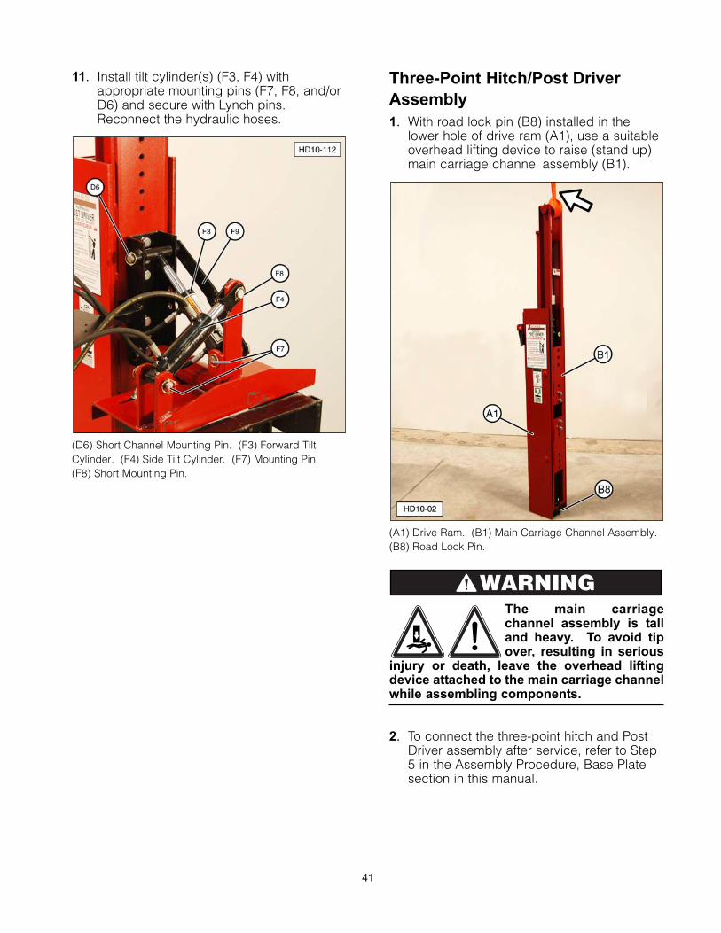
11. Install tilt cylinder(s) (F3, F4) withappropriate mounting pins (F7, F8, and/orD6) and secure with Lynch pins.Reconnect the hydraulic hoses.
(D6) Short Channel Mounting Pin. (F3) Forward TiltCylinder. (F4) Side Tilt Cylinder. (F7) Mounting Pin. (F8) Short Mounting Pin.
Three-Point Hitch/Post Driver
Assembly
1. With road lock pin (B8) installed in thelower hole of drive ram (A1), use a suitableoverhead lifting device to raise (stand up)main carriage channel assembly (B1).
(A1) Drive Ram. (B1) Main Carriage Channel Assembly. (B8) Road Lock Pin.
The main carriagechannel assembly is talland heavy. To avoid tipover, resulting in serious
injury or death, leave the overhead liftingdevice attached to the main carriage channelwhile assembling components.
2. To connect the three-point hitch and PostDriver assembly after service, refer to Step5 in the Assembly Procedure, Base Platesection in this manual.
WARNING
41
42
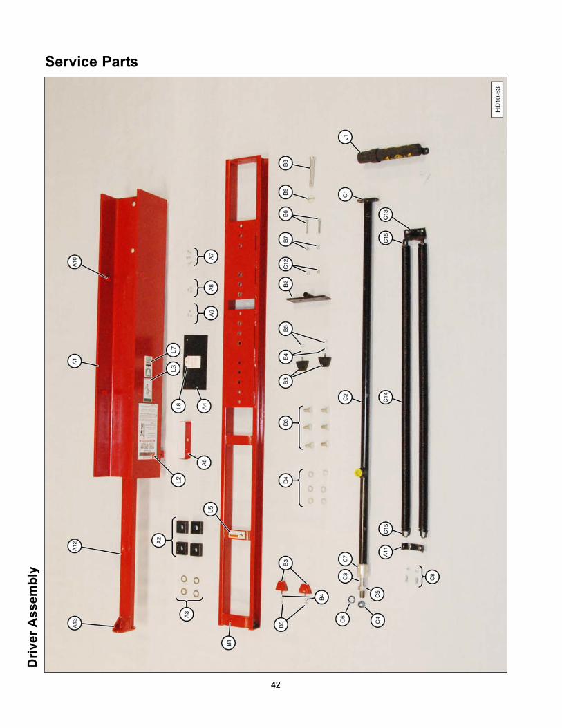
Service Parts
42
Dri
ver
Ass
em
bly
Dri
ver
Ass
em
bly
HD
-10 S
erv
ice P
art
s -
Dri
ver
Assem
bly
Item
No
.P
art
No
.D
escri
pti
on
Qty
.
A1
SM
-101
1-D
RC
Driv
ing
Ram
Com
ple
te1
SM
-101
1-D
RO
Driv
ing
Ram
Onl
y1
A2
SM
-005
12G
uid
e B
lock
Pkg
. of 4
A3
SM
-093
3-(1
8 g
a)S
him
4
SM
-903
4-(1
4 g
a)S
M-0
935-
(10
ga)
A4
SM
-101
1-G
Rub
ber
Deb
ris G
uard
11
A5
Gua
rd M
ount
ing
Str
ap1
L8C
autio
n Ta
g1
A7
Gua
rd M
ount
ing
Bol
t3
A8
Gua
rd M
ount
ing
Was
her
3
A9
Gua
rd M
ount
ing
Nut
3
A11
SM
-101
1-S
BU
Up
per
Sp
ring
Bra
cket
1
B1
SM
-104
12M
ain
Car
riag
e C
hann
el1
B2
SM
-104
1-R
LBR
oad
Loc
k B
rack
et
1(n
o p
in)
B3
SM
-004
1-B
Rub
ber
Bum
per
24
B4
Bum
per
Loc
k W
ashe
r, 5
/16
4
B5
Bum
per
Nut
, 5/1
6-18
4
B6
SM
-093
Roa
d L
ock
Bra
cket
Bol
t2
B7
SM
-932
Roa
d L
ock
Bra
cket
Nut
2
B8
SM
-104
1-R
LPR
oad
Loc
k P
in1
B9
SM
-104
1-R
LCR
oad
Loc
k P
in C
lip1
C1
SM
-102
6C
ylin
der
Ass
emb
ly1
C2
SM
-102
61C
ylin
der
Tub
e1
C3
SM
-102
66C
ylin
der
Pis
ton/
Rod
1
C4
SM
-102
67P
isto
n S
elf-
Lock
ing
Nut
1
C5
SM
-018
Cyl
ind
er N
ut
1(w
ith s
etsc
rew
)
C6
SM
-102
68Lo
ck W
ashe
r1
C7
SM
-102
62-D
Cyl
ind
er C
ap
1(w
ith s
eal)
HD
-10 S
erv
ice P
art
s -
Dri
ver
Assem
bly
(co
nti
nu
ed
)
Item
No
.P
art
No
.D
escri
pti
on
Qty
.
C8
—B
olts
, Loc
k W
ashe
rs, N
uts
2(u
pp
er s
prin
g b
rack
et)
C12
SM
-093
1Lo
wer
Bra
cket
Loc
k N
ut2
C13
SM
-101
1-S
BL
Low
er S
prin
g B
rack
et1
C14
SM
-101
1-D
RS
Sp
ring
2(w
ith s
prin
g c
lips
inst
alle
d)
C15
SM
-101
1-S
CS
prin
g C
lip O
nly
4
D3
S-0
12S
hort
Bra
cket
Bol
ts
45/
8-11
x 1
-1/4
D4
S-0
13S
hort
Bra
cket
Loc
k W
ashe
r, 5
/84
D5
—S
hort
Bra
cket
Nut
, 5/8
-11
4
J1O
DM
AN
Doc
umen
t Sto
rag
e Tu
be
1
L2M
S-1
61La
rge
“SH
AV
ER
” D
ecal
1
L3M
S-1
69C
ontr
ol V
alve
Dec
al1
L5M
S-1
81P
inch
Are
a W
arni
ng D
ecal
1
L7M
S-2
80FE
MA
Mem
ber
Dec
al1
L9M
S-1
80C
ylin
der
Sha
ft Lo
ose
Dec
al
1(n
ot v
isib
le)
1S
M-1
011-
G In
clud
es It
ems
A4,
A5,
L8,
A7,
A8,
and
A9.
2S
M-1
041-
B In
clud
es It
ems
B3,
B4,
and
B5.
Dri
ve R
am
Weld
men
t P
art
s
HD
-10 S
erv
ice P
art
s -
Dri
ve R
am
Weld
men
t
Item
No
.P
art
No
.D
escri
pti
on
Qty
.
A10
SM
-101
1-B
SG
uid
e P
ins
14
A12
SM
-101
1-LY
BLi
ft Y
oke
Bar
11
A13
SM
-101
1-LY
TSLi
ft Yo
ke T
op 1
11
Rep
lace
men
t of t
hese
par
ts r
equi
res
rem
oval
of o
ld p
arts
with
a c
uttin
g to
rch
and
/or
grin
din
g w
heel
. N
ew (
rep
lace
men
t) p
arts
mus
t be
wel
ded
to d
rive
ram
. Th
is ty
pe
ofre
pai
r vo
ids
any
war
rant
ies.
43
4444
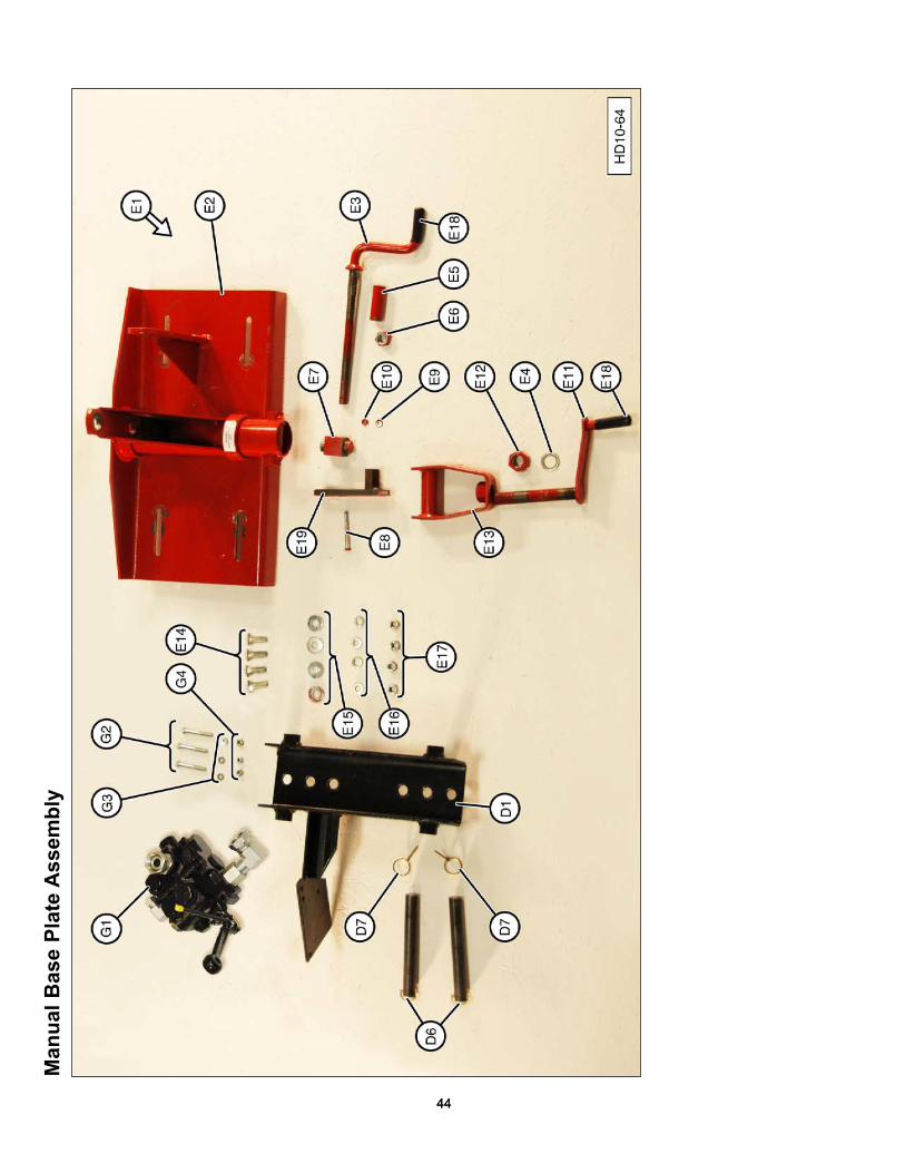
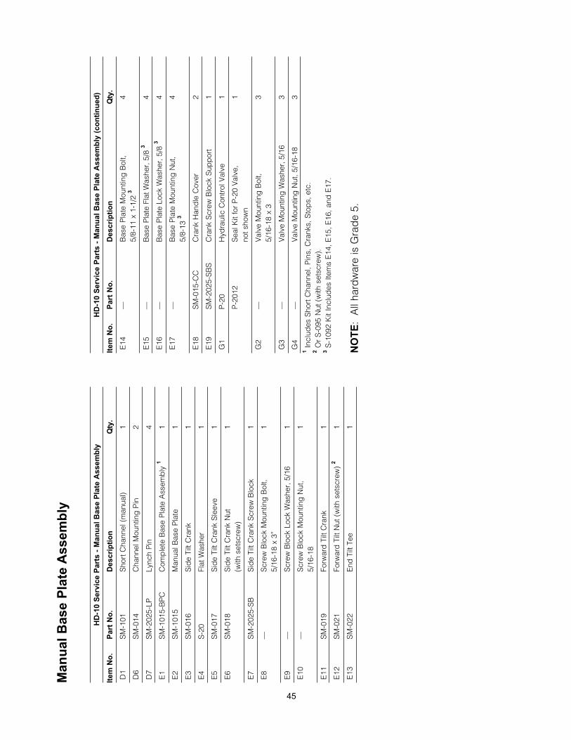
Man
ual
Ba
se P
late
Assem
bly
Man
ual
Ba
se P
late
Assem
bly
HD
-10 S
erv
ice P
art
s -
Man
ual
Base P
late
Assem
bly
Item
No
.P
art
No
.D
escri
pti
on
Qty
.
D1
SM
-101
Sho
rt C
hann
el (
man
ual)
1
D6
SM
-014
Cha
nnel
Mou
ntin
g P
in2
D7
SM
-202
5-LP
Lync
h P
in4
E1
SM
-101
5-B
PC
Com
ple
te B
ase
Pla
te A
ssem
bly
11
E2
SM
-101
5M
anua
l Bas
e P
late
1
E3
SM
-016
Sid
e Ti
lt C
rank
1
E4
S-2
0Fl
at W
ashe
r1
E5
SM
-017
Sid
e Ti
lt C
rank
Sle
eve
1
E6
SM
-018
Sid
e Ti
lt C
rank
Nut
1(w
ith s
etsc
rew
)
E7
SM
-202
5-S
BS
ide
Tilt
Cra
nk S
crew
Blo
ck1
E8
—S
crew
Blo
ck M
ount
ing
Bol
t,1
5/16
-18
x 3”
E9
—S
crew
Blo
ck L
ock
Was
her,
5/1
61
E10
—S
crew
Blo
ck M
ount
ing
Nut
,1
5/16
-18
E11
SM
-019
Forw
ard
Tilt
Cra
nk1
E12
SM
-021
Forw
ard
Tilt
Nut
(w
ith s
etsc
rew
) 2
1
E13
SM
-022
End
Tilt
Tee
1
HD
-10 S
erv
ice P
art
s -
Man
ual
Base P
late
Assem
bly
(co
nti
nu
ed
)
Item
No
.P
art
No
.D
escri
pti
on
Qty
.
E14
—B
ase
Pla
te M
ount
ing
Bol
t,4
5/8-
11 x
1-1
/2 3
E15
—B
ase
Pla
te F
lat W
ashe
r, 5
/8 3
4
E16
—B
ase
Pla
te L
ock
Was
her,
5/8
34
E17
—B
ase
Pla
te M
ount
ing
Nut
, 4
5/8-
13 3
E18
SM
-015
-CC
Cra
nk H
and
le C
over
2
E19
SM
-202
5-S
BS
Cra
nk S
crew
Blo
ck S
upp
ort
1
G1
P-2
0H
ydra
ulic
Con
trol
Val
ve1
P-2
012
Sea
l Kit
for
P-2
0 V
alve
,1
not s
how
n
G2
—V
alve
Mou
ntin
g B
olt,
35/
16-1
8 x
3
G3
—V
alve
Mou
ntin
g W
ashe
r, 5
/16
3
G4
—V
alve
Mou
ntin
g N
ut, 5
/16-
183
1In
clud
es S
hort
Cha
nnel
, Pin
s, C
rank
s, S
top
s, e
tc.
2O
r S
-095
Nut
(w
ith s
etsc
rew
).3
S-1
092
Kit
Incl
udes
Item
s E
14, E
15, E
16, a
nd E
17.
NO
TE
: A
ll ha
rdw
are
is G
rad
e 5.
45
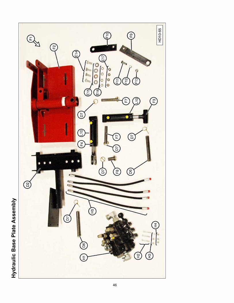
46
Hyd
rau
lic B
ase P
late
Assem
bly
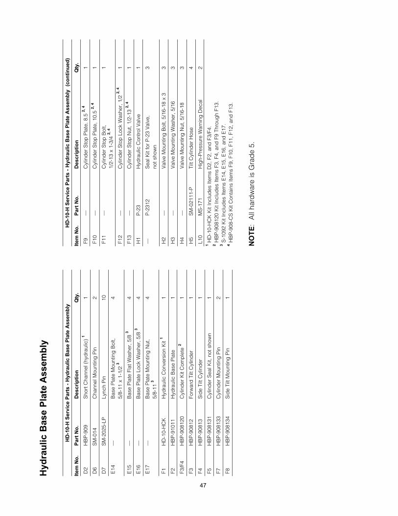
47
Hyd
rau
lic B
ase P
late
Assem
bly
HD
-10-H
Serv
ice P
art
s -
Hyd
rau
lic B
ase P
late
Assem
bly
Item
No
.P
art
No
.D
escri
pti
on
Qty
.
D2
HB
P-9
09S
hort
Cha
nnel
(hy
dra
ulic
) 1
1
D6
SM
-014
Cha
nnel
Mou
ntin
g P
in2
D7
SM
-202
5-LP
Lync
h P
in10
E14
—B
ase
Pla
te M
ount
ing
Bol
t,4
5/8-
11 x
1-1
/2 3
E15
—B
ase
Pla
te F
lat W
ashe
r, 5
/8 3
4
E16
—B
ase
Pla
te L
ock
Was
her,
5/8
34
E17
—B
ase
Pla
te M
ount
ing
Nut
,4
5/8-
11 3
F1H
D-1
0-H
CK
Hyd
raul
ic C
onve
rsio
n K
it 1
1
F2H
BP
-910
11H
ydra
ulic
Bas
e P
late
1
F3/F
4H
BP
-908
120
Cyl
ind
er K
it C
omp
lete
21
F3H
BP
-908
12Fo
rwar
d T
ilt C
ylin
der
1
F4H
BP
-908
13S
ide
Tilt
Cyl
ind
er1
F5H
BP
-908
131
Cyl
ind
er S
eal K
it, n
ot s
how
n 1
F7H
BP
-908
133
Cyl
ind
er M
ount
ing
Pin
2
F8H
BP
-908
134
Sid
e Ti
lt M
ount
ing
Pin
1
HD
-10-H
Serv
ice P
art
s -
Hyd
rau
lic B
ase P
late
Assem
bly
(c
on
tin
ued
)
Item
No
.P
art
No
.D
escri
pti
on
Qty
.
F9—
Cyl
ind
er S
top
Pla
te, 8
.5 2
, 4
1
F10
—C
ylin
der
Sto
p P
late
, 10.
5 2,
41
F11
—C
ylin
der
Sto
p B
olt,
11/
2-13
x 1
-3/4
2,
4
F12
—C
ylin
der
Sto
p L
ock
Was
her,
1/2
2,
41
F13
—C
ylin
der
Sto
p N
ut, 1
/2-1
3 2,
41
H1
P-2
3H
ydra
ulic
Con
trol
Val
ve1
—P
-231
2S
eal K
it fo
r P
-23
Val
ve,
3no
t sho
wn
H2
—V
alve
Mou
ntin
g B
olt,
5/16
-18
x 3
3
H3
—V
alve
Mou
ntin
g W
ashe
r, 5
/16
3
H4
—V
alve
Mou
ntin
g N
ut, 5
/16-
183
H5
SM
-021
11-P
Tilt
Cyl
ind
er H
ose
4
L10
MS
-171
Hig
h-P
ress
ure
War
ning
Dec
al2
1H
D-1
0-H
CK
Kit
Incl
udes
Item
s D
2, F
2, a
nd F
3/F4
.2
HB
P-9
0812
0 K
it In
clud
es It
ems
F3, F
4, a
nd F
9 Th
roug
h F1
3.3
S-1
092
Kit
Incl
udes
Item
s E
14, E
15, E
16, a
nd E
17.
4H
BP
-908
-CS
Kit
Con
tain
s Ite
ms
F9, F
10, F
11, F
12, a
nd F
13.
NO
TE
: A
ll ha
rdw
are
is G
rad
e 5.
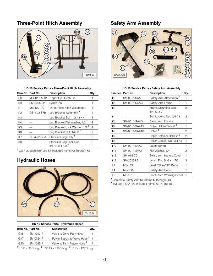
Three-Point Hitch Assembly
HD-10 Service Parts - Three-Point Hitch Assembly
Item No. Part No. Description Qty.
B8 MB-1201A-12 Upper Link Hitch Pin 1
B9 SM-2025-LP Lynch Pin 1
K1 MB-1201-A Three-Point Hitch Weldment 1
K2 OS-4-22-SFB Leg Bracket Weldment 1 2
K3 — Leg Bracket Bolt, 1/2-13 x 4 1 2
K4 — Leg Bracket Flat Washer, 1/2 1 2
K5 — Leg Bracket Lock Washer, 1/2 1 2
K6 — Leg Bracket Nut, 1/2-13 1 2
K7 OS-4-22-SSA Stabilizer Leg Only 1 2
K8 — Stabilizer Leg Lock Bolt, 25/8-11 x 1-1/2 1
1 OS-4-22 Stabilizer Leg Kit Includes Items K2 Through K8.
Hydraulic Hoses
HD-10 Service Parts - Hydraulic Hoses
Item No. Part No. Description Qty.
G15 SM-1023-P Valve to Drive Ram Hose 1 1
G17 SM-0234-P Power Supply to Valve Hose 2 1
G20 SM-1025-R Valve to Tank Return Hose 3 11 1” ID x 35” long. 2 1/2” ID x 120” long. 3 1” ID x 120” long.
Safety Arm Assembly
HD-10 Service Parts - Safety Arm Assembly
Item No. Part No. Description Qty.
I1 SM-0011-SAA Safety Arm Attachment 1 1
I2 SM-0011-SAAC Safety Arm Frame 1
I3 — Frame Mounting Bolt, 23/4-13 x 2
I4 — Self-Locking Nut, 3/4-13 2
I5 SM-0011-SAAD Swing Arm Handle 1
I6 SM-0011-SAA15 Roller Holder Swivel 2 1
I7 SM-0011-SAA16 Roller 2 2
I8 Roller Retainer Roll Pin 2 2
I9 Roller Bracket Nut, 3/4-13 1
I10 SM-0011-SAA2 Latch Spring 1
I11 SM-0011-SAA7 Flat Washer, 3/4 2
I12 SM-015-CC Swing Arm Handle Cover 1
I13 SM-2025-LP Lynch Pin, 3/16 x 1-7/8 3
L1 MS-165 Small “SHAVER” Decal 1
L4 MS-166 Safety Arm Decal 1
L6 MS-181 Pinch Area Warning Decal 11 Complete Safety Arm Kit (Items I2 through L6). 2 SM-0011-SAA13C Includes Items I6, I7, and I8.
4848
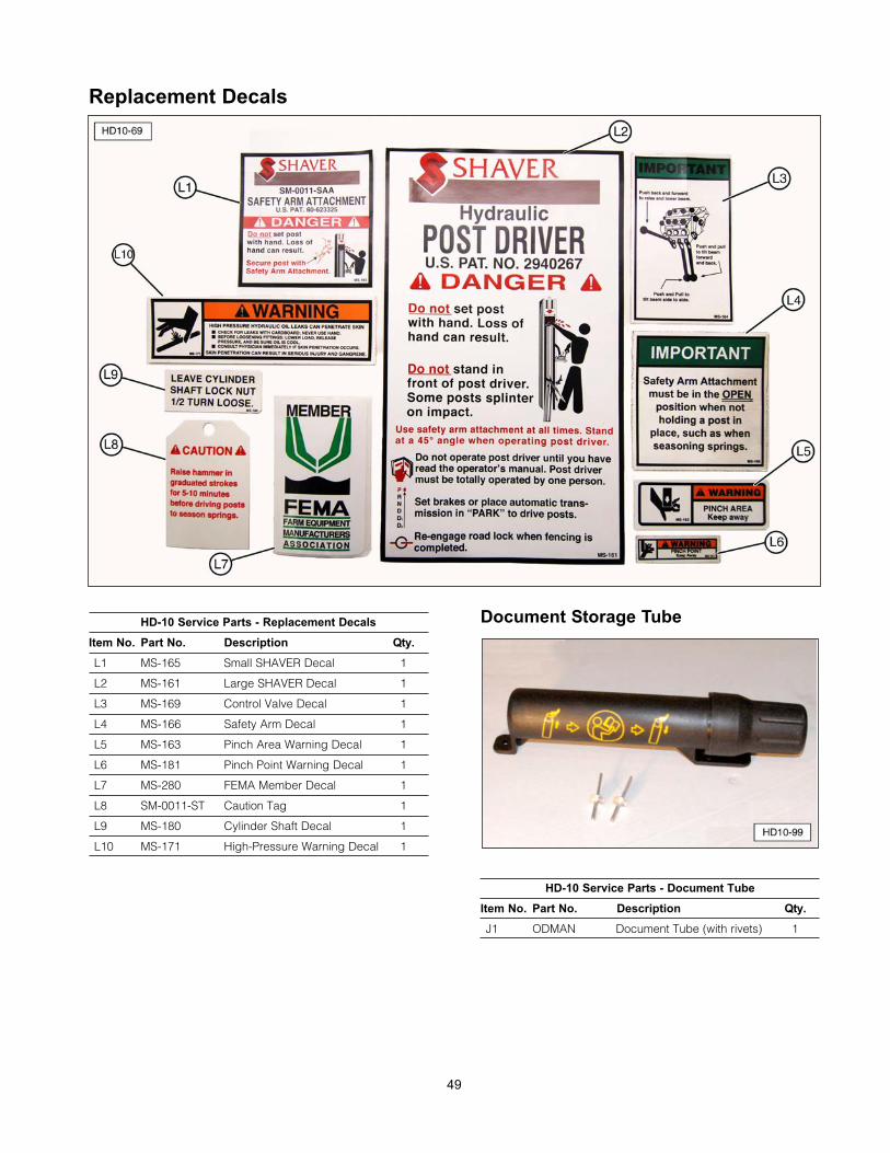
Replacement Decals
HD-10 Service Parts - Replacement Decals
Item No. Part No. Description Qty.
L1 MS-165 Small SHAVER Decal 1
L2 MS-161 Large SHAVER Decal 1
L3 MS-169 Control Valve Decal 1
L4 MS-166 Safety Arm Decal 1
L5 MS-163 Pinch Area Warning Decal 1
L6 MS-181 Pinch Point Warning Decal 1
L7 MS-280 FEMA Member Decal 1
L8 SM-0011-ST Caution Tag 1
L9 MS-180 Cylinder Shaft Decal 1
L10 MS-171 High-Pressure Warning Decal 1
Document Storage Tube
HD-10 Service Parts - Document Tube
Item No. Part No. Description Qty.
J1 ODMAN Document Tube (with rivets) 1
49
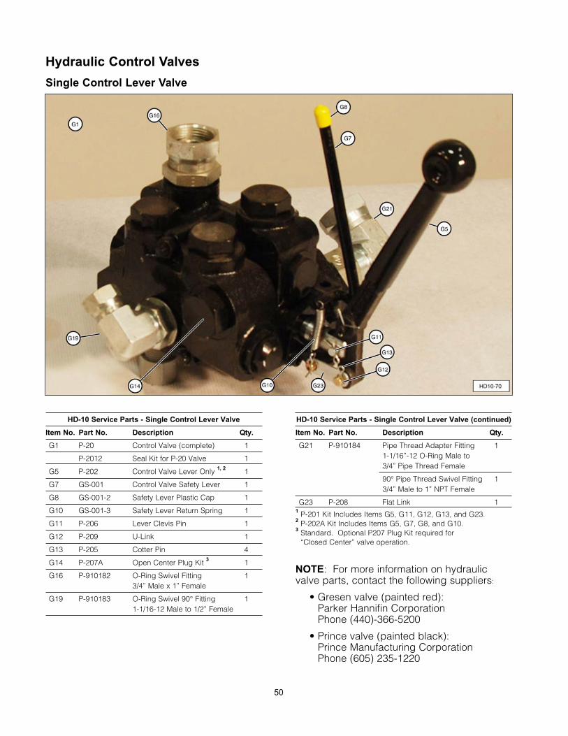
50
Hydraulic Control Valves
Single Control Lever Valve
HD-10 Service Parts - Single Control Lever Valve
Item No. Part No. Description Qty.
G1 P-20 Control Valve (complete) 1
P-2012 Seal Kit for P-20 Valve 1
G5 P-202 Control Valve Lever Only 1, 2 1
G7 GS-001 Control Valve Safety Lever 1
G8 GS-001-2 Safety Lever Plastic Cap 1
G10 GS-001-3 Safety Lever Return Spring 1
G11 P-206 Lever Clevis Pin 1
G12 P-209 U-Link 1
G13 P-205 Cotter Pin 4
G14 P-207A Open Center Plug Kit 3 1
G16 P-910182 O-Ring Swivel Fitting 13/4” Male x 1” Female
G19 P-910183 O-Ring Swivel 90° Fitting 11-1/16-12 Male to 1/2” Female
HD-10 Service Parts - Single Control Lever Valve (continued)
Item No. Part No. Description Qty.
G21 P-910184 Pipe Thread Adapter Fitting 11-1/16”-12 O-Ring Male to 3/4” Pipe Thread Female
90° Pipe Thread Swivel Fitting 13/4” Male to 1” NPT Female
G23 P-208 Flat Link 11 P-201 Kit Includes Items G5, G11, G12, G13, and G23.2 P-202A Kit Includes Items G5, G7, G8, and G10.3 Standard. Optional P207 Plug Kit required for
“Closed Center” valve operation.
NOTE: For more information on hydraulicvalve parts, contact the following suppliers:
• Gresen valve (painted red): Parker Hannifin Corporation Phone (440)-366-5200
• Prince valve (painted black):Prince Manufacturing CorporationPhone (605) 235-1220
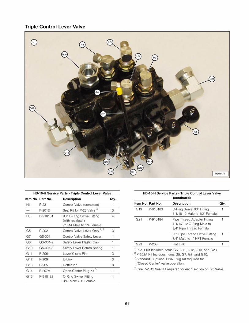
Triple Control Lever Valve
HD-10-H Service Parts - Triple Control Lever Valve
Item No. Part No. Description Qty.
H1 P-23 Control Valve (complete) 1
— P-2012 Seal Kit for P-23 Valve 4 3
H3 P-910181 90° O-Ring Swivel Fitting 4(with restricter)7/8-14 Male to 1/4 Female
G5 P-202 Control Valve Lever Only 1, 2 3
G7 GS-001 Control Valve Safety Lever 1
G8 GS-001-2 Safety Lever Plastic Cap 1
G10 GS-001-3 Safety Lever Return Spring 1
G11 P-206 Lever Clevis Pin 3
G12 P-209 U-Link 3
G13 P-205 Cotter Pin 8
G14 P-207A Open Center Plug Kit 3 1
G16 P-910182 O-Ring Swivel Fitting 13/4” Male x 1” Female
HD-10-H Service Parts - Triple Control Lever Valve
(continued)
Item No. Part No. Description Qty.
G19 P-910183 O-Ring Swivel 90° Fitting 11-1/16-12 Male to 1/2” Female
G21 P-910184 Pipe Thread Adapter Fitting 11-1/16”-12 O-Ring Male to 3/4” Pipe Thread Female
90° Pipe Thread Swivel Fitting 13/4” Male to 1” NPT Female
G23 P-208 Flat Link 11 P-201 Kit Includes Items G5, G11, G12, G13, and G23.2 P-202A Kit Includes Items G5, G7, G8, and G10.3 Standard. Optional P207 Plug Kit required for
“Closed Center” valve operation.4 One P-2012 Seal Kit required for each section of P23 Valve.
51
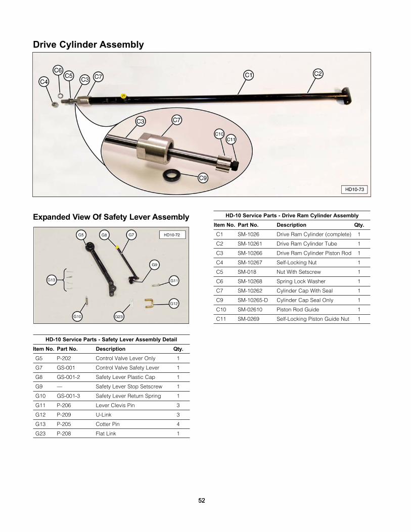
Drive Cylinder Assembly
Expanded View Of Safety Lever Assembly
HD-10 Service Parts - Safety Lever Assembly Detail
Item No. Part No. Description Qty.
G5 P-202 Control Valve Lever Only 1
G7 GS-001 Control Valve Safety Lever 1
G8 GS-001-2 Safety Lever Plastic Cap 1
G9 — Safety Lever Stop Setscrew 1
G10 GS-001-3 Safety Lever Return Spring 1
G11 P-206 Lever Clevis Pin 3
G12 P-209 U-Link 3
G13 P-205 Cotter Pin 4
G23 P-208 Flat Link 1
HD-10 Service Parts - Drive Ram Cylinder Assembly
Item No. Part No. Description Qty.
C1 SM-1026 Drive Ram Cylinder (complete) 1
C2 SM-10261 Drive Ram Cylinder Tube 1
C3 SM-10266 Drive Ram Cylinder Piston Rod 1
C4 SM-10267 Self-Locking Nut 1
C5 SM-018 Nut With Setscrew 1
C6 SM-10268 Spring Lock Washer 1
C7 SM-10262 Cylinder Cap With Seal 1
C9 SM-10265-D Cylinder Cap Seal Only 1
C10 SM-02610 Piston Rod Guide 1
C11 SM-0269 Self-Locking Piston Guide Nut 1
5252
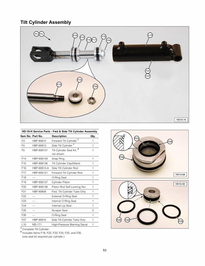
53
Tilt Cylinder Assembly
HD-10-H Service Parts - Fwd & Side Tilt Cylinder Assembly
Item No. Part No. Description Qty.
F3 HBP-90812 Forward Tilt Cylinder 1 1
F4 HBP-90813 Side Tilt Cylinder 1 1
F5 HBP-908131 Tilt Cylinder Seal Kit, 2 1not shown
F14 HBP-908139 Snap Ring 1
F15 HBP-908136 Tilt Cylinder Cap/Gland 1
F16 HBP-90813-A Side Tilt Cylinder Rod 1
F17 HBP-908121 Forward Tilt Cylinder Rod 1
F18 — O-Ring Seal 1
F19 HBP-908137 Cylinder Piston 1
F20 HBP-908138 Piston Rod Self-Locking Nut 1
F21 HBP-90809 Fwd. Tilt Cylinder Tube Only 1
F22 — External O-Ring Seal 1
F23 — Internal O-Ring Seal 1
F24 — Internal Lip Seal 1
F25 — Scraper Seal 2
F26 — O-Ring Seal 1
F27 HBP-90810 Side Tilt Cylinder Tube Only 1
L10 MS-171 High-Pressure Warning Decal 11 Complete Tilt Cylinder.2 Includes Items F18, F22, F23, F24, F25, and F26.
(one seal kit required per cylinder.)

LLiimmiitteedd WWaarrrraannttyyShaver Manufacturing Company, LLC warrants each new Shaver product to be free from defects inmaterial and workmanship. This warranty is applicable only for the normal service life expectancy ofthe product or components, not to exceed 12 consecutive months from the date of delivery of thenew Shaver product to the original purchaser.
Genuine Shaver replacement parts and components will be warranted for 90 days from the date ofpurchase, or the remainder of the original equipment warranty period, whichever is longer.
Rubber Bumpers, Carbide Teeth, Auger Teeth and Auger Points are usable parts and not covered bywarranty. Part No. SD-101-GB and SD-0301-GB Gearbox are warranted for 3 years from the date ofpurchase. Part No. SD-0607-GB and SD-0907-GB Gearbox are warranted for 5 years from the dateof purchase. Part No. SL-2030-1 5” Cylinder for the Logsplitter is warranted for 4 years from the dateof purchase. Driving Ram Springs are warranted for 60 days from the date of purchase forresidential customers and 30 days from the date of purchase with a limit of 2 claims per serialnumbered unit for commercial users. Tires are warranted for 90 days from the date of purchase.
Under no circumstances will it cover any merchandise or components thereof, which, in the opinionof the company, have been subjected to misuse, unauthorized modification, alteration, an accident,or if a repair has been made with parts other than those obtainable through Shaver.
Our obligation under this warranty shall be limited to repairing or replacing any part that, in ourjudgment, shall show evidence of such defect, provided further that such part shall be returnedwithin thirty (30) days from the date of failure to Shaver, routed through the dealer and distributorfrom whom the purchase was made, transportation charges prepaid. All returned items must havean RGA number. Contact Shaver at 712-859-3293 to get authorization to return, file your warrantyclaim and, if needed, an RGA will be provided.
This warranty shall not be interpreted to render Shaver liable for injury or damages of any kind ornature to person or property. This warranty does not extend to the loss of crops, loss because ofdelay in harvesting, or any expense or loss incurred for labor, substitute machinery, rental, or for anyother reason.
Except as set forth above, Shaver shall have no obligation or liability of any kind on account ofany of its equipment and shall not be liable for special or consequential damages. Shavermakes no other warranty, expressed or implied, and specifically, Shaver disclaims any impliedwarranty of merchantability or fitness for a particular purpose. Some states or provinces donot permit limitations or exclusions of implied warranties or incidental or consequentialdamages, so the limitations or exclusion in this warranty may not apply..
This warranty is subject to any existing conditions of supply which may directly affect our ability toobtain materials or manufacture replacement parts.
Shaver reserves the right to make improvements in design or changes in specifications at any time,without incurring any obligation to owners of units previously sold.
No one is authorized to alter, modify, or enlarge this warranty, nor the exclusion, limitations, andreservations.
Effective January 1, 2009
5454
SShhaavveerr MMaannuuffaaccttuurriinngg CCoo..,, LLLLCC..110033 SSoouutthh WWaasshhiinnggttoonn AAvveennuuee
PP..OO.. BBooxx 335588GGrraaeettttiinnggeerr,, IIAA 5511334422
PPhhoonnee:: ((771122)) 885599--33229933FFaaxx:: ((771122)) 885599--33229944
ssaalleess@@sshhaavveerrmmffgg..ccoomm
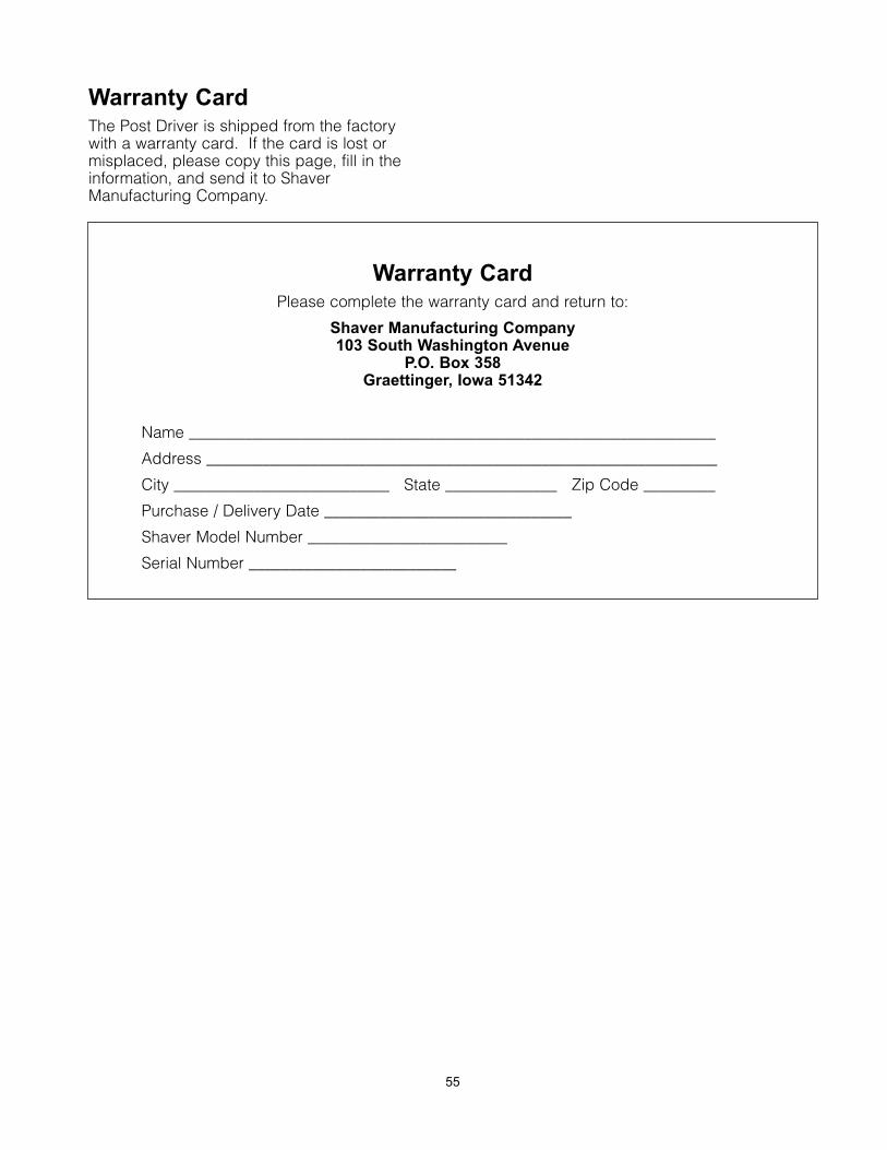
Warranty CardThe Post Driver is shipped from the factorywith a warranty card. If the card is lost ormisplaced, please copy this page, fill in theinformation, and send it to ShaverManufacturing Company.
55
Warranty CardPlease complete the warranty card and return to:
Shaver Manufacturing Company103 South Washington Avenue
P.O. Box 358Graettinger, Iowa 51342
Name __________________________________________________________________
Address ________________________________________________________________
City ___________________________ State ______________ Zip Code _________
Purchase / Delivery Date _______________________________
Shaver Model Number _________________________
Serial Number __________________________

April 2009SHAVER HD-10 and HD-10-H Post Driver
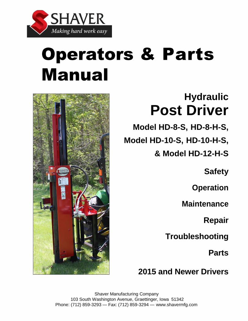
Operators & Parts
Manual
Hydraulic
Post Driver
Model HD-8-S, HD-8-H-S,
Model HD-10-S, HD-10-H-S,
& Model HD-12-H-S
Safety
Operation
Maintenance
Repair
Troubleshooting
Parts
2015 and Newer Drivers
Shaver Manufacturing Company
103 South Washington Avenue, Graettinger, Iowa 51342
Phone: (712) 859-3293 — Fax: (712) 859-3294 — www.shavermfg.com
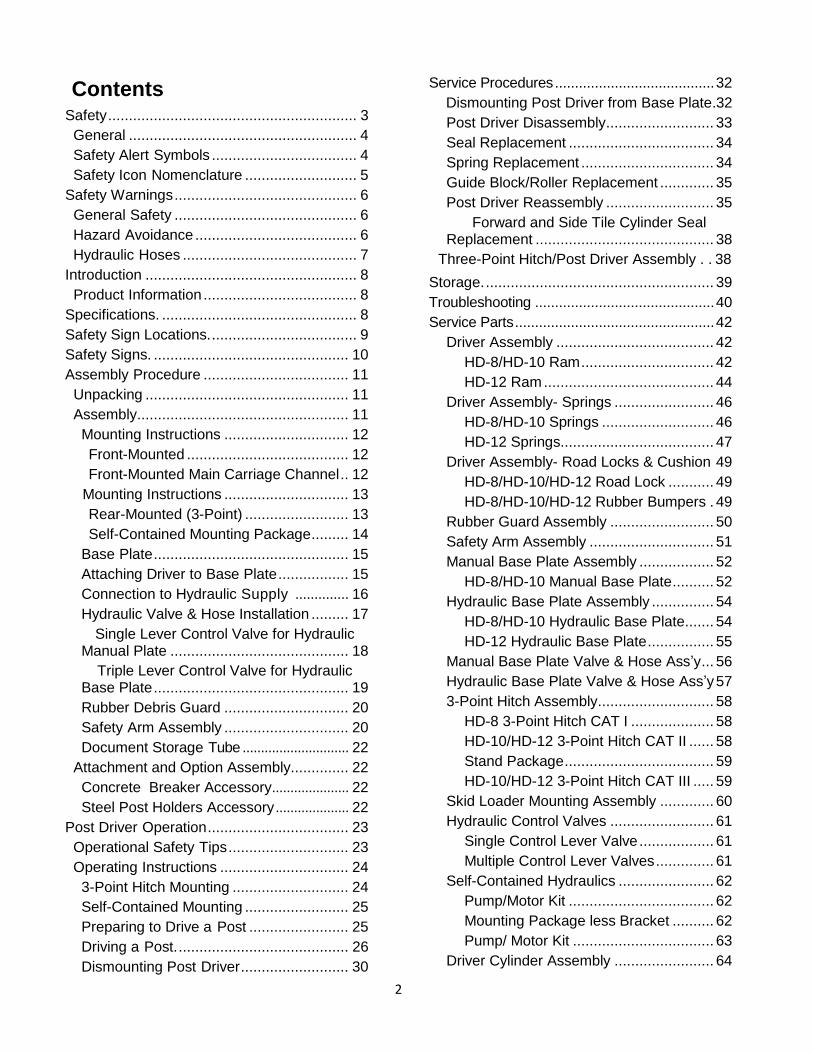
2
Contents Safety ............................................................ 3
General ....................................................... 4
Safety Alert Symbols ................................... 4
Safety Icon Nomenclature ........................... 5
Safety Warnings ............................................ 6
General Safety ............................................ 6
Hazard Avoidance ....................................... 6
Hydraulic Hoses .......................................... 7
Introduction ................................................... 8
Product Information ..................................... 8
Specifications. ............................................... 8
Safety Sign Locations. ................................... 9
Safety Signs. ............................................... 10
Assembly Procedure ................................... 11
Unpacking ................................................. 11
Assembly ................................................... 11
Mounting Instructions .............................. 12
Front-Mounted ....................................... 12
Front-Mounted Main Carriage Channel .. 12
Mounting Instructions .............................. 13
Rear-Mounted (3-Point) ......................... 13
Self-Contained Mounting Package ......... 14
Base Plate ............................................... 15
Attaching Driver to Base Plate ................. 15
Connection to Hydraulic Supply .............. 16
Hydraulic Valve & Hose Installation ......... 17
Single Lever Control Valve for Hydraulic Manual Plate ........................................... 18
Triple Lever Control Valve for Hydraulic Base Plate ............................................... 19
Rubber Debris Guard .............................. 20
Safety Arm Assembly .............................. 20
Document Storage Tube ............................. 22
Attachment and Option Assembly.............. 22
Concrete Breaker Accessory..................... 22
Steel Post Holders Accessory .................... 22
Post Driver Operation .................................. 23
Operational Safety Tips ............................. 23
Operating Instructions ............................... 24
3-Point Hitch Mounting ............................ 24
Self-Contained Mounting ......................... 25
Preparing to Drive a Post ........................ 25
Driving a Post. ......................................... 26
Dismounting Post Driver .......................... 30
Service Procedures ........................................ 32
Dismounting Post Driver from Base Plate.32
Post Driver Disassembly .......................... 33
Seal Replacement ................................... 34
Spring Replacement ................................ 34
Guide Block/Roller Replacement ............. 35
Post Driver Reassembly .......................... 35
Forward and Side Tile Cylinder Seal Replacement ........................................... 38
Three-Point Hitch/Post Driver Assembly . . 38
Storage. ....................................................... 39
Troubleshooting ............................................. 40
Service Parts .................................................. 42
Driver Assembly ...................................... 42
HD-8/HD-10 Ram ................................ 42
HD-12 Ram ......................................... 44
Driver Assembly- Springs ........................ 46
HD-8/HD-10 Springs ........................... 46
HD-12 Springs..................................... 47
Driver Assembly- Road Locks & Cushion 49
HD-8/HD-10/HD-12 Road Lock ........... 49
HD-8/HD-10/HD-12 Rubber Bumpers . 49
Rubber Guard Assembly ......................... 50
Safety Arm Assembly .............................. 51
Manual Base Plate Assembly .................. 52
HD-8/HD-10 Manual Base Plate .......... 52
Hydraulic Base Plate Assembly ............... 54
HD-8/HD-10 Hydraulic Base Plate ....... 54
HD-12 Hydraulic Base Plate ................ 55
Manual Base Plate Valve & Hose Ass’y ... 56
Hydraulic Base Plate Valve & Hose Ass’y 57
3-Point Hitch Assembly............................ 58
HD-8 3-Point Hitch CAT I .................... 58
HD-10/HD-12 3-Point Hitch CAT II ...... 58
Stand Package .................................... 59
HD-10/HD-12 3-Point Hitch CAT III ..... 59
Skid Loader Mounting Assembly ............. 60
Hydraulic Control Valves ......................... 61
Single Control Lever Valve .................. 61
Multiple Control Lever Valves .............. 61
Self-Contained Hydraulics ....................... 62
Pump/Motor Kit ................................... 62
Mounting Package less Bracket .......... 62
Pump/ Motor Kit .................................. 63
Driver Cylinder Assembly ........................ 64
3
Attachments-Pilot Augers ........................ 65
Auger Assembly 4” & 6” ...................... 65
6” Auger Fish Tail & Tooth Assembly .. 66
Motor & Hose Assembly ..................... 67
Motor Mount Plate Assembly .............. 67
Attachments-Concrete Breakers ............. 68
Attachments-Steel Post Holders .............. 69
Attachments-Post Holders ....................... 69
Replacement Decals ............................... 70
Limited Warranty ............................................ 70
Warranty Card ................................................ 72
Safety Most work related accidents are caused by failure to observe basic safety rules or precautions. An accident can often b e avoided by recognizing potentially hazardous situations before an accident occurs. As you assemble and operate the Shaver Post Driver, you must be alert to potential hazards. You should also have the necessary training, skills, and tools to perform this assembly procedure.
Improper operation and maintenance of this implement could result in a dangerous situation that could cause injury or death.
Do not assemble, operate, or maintain the Shaver Post Driver until you read and understand the information contained in this manual.
Safety precautions and warnings are provided in this manual and on the product. If these hazard warnings are not heeded, bodily injury or death could occur to you or to other persons.
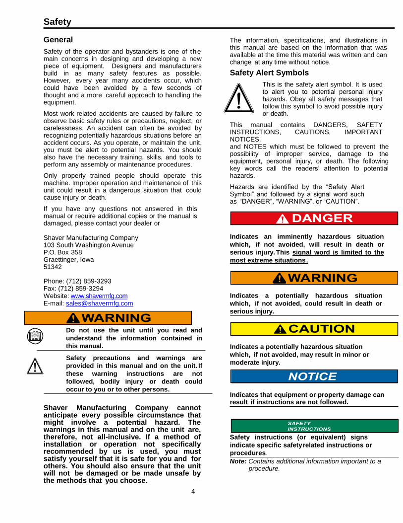
4
Safety
General
Safety of the operator and bystanders is one of the main concerns in designing and developing a new piece of equipment. Designers and manufacturers build in as many safety features as possible. However, every year many accidents occur, which could have been avoided by a few seconds of thought and a more careful approach to handling the equipment.
Most work-related accidents are caused by failure to observe basic safety rules or precautions, neglect, or carelessness. An accident can often be avoided by recognizing potentially hazardous situations before an accident occurs. As you operate, or maintain the unit, you must be alert to potential hazards. You should also have the necessary training, skills, and tools to perform any assembly or maintenance procedures.
Only properly trained people should operate this machine. Improper operation and maintenance of this unit could result in a dangerous situation that could cause injury or death.
If you have any questions not answered in this manual or require additional copies or the manual is damaged, please contact your dealer or
Shaver Manufacturing Company 103 South Washington Avenue P.O. Box 358 Graettinger, Iowa 51342
Phone: (712) 859-3293 Fax: (712) 859-3294 Website: www.shavermfg.com E-mail: [email protected]
Do not use the unit until you read and
understand the information contained in
this manual.
Safety precautions and warnings are
provided in this manual and on the unit. If
these warning instructions are not
followed, bodily injury or death could
occur to you or to other persons.
Shaver Manufacturing Company cannot anticipate every possible circumstance that might involve a potential hazard. The warnings in this manual and on the unit are, therefore, not all-inclusive. If a method of installation or operation not specifically recommended by us is used, you must satisfy yourself that it is safe for you and for others. You should also ensure that the unit will not be damaged or be made unsafe by the methods that you choose.
The information, specifications, and illustrations in this manual are based on the information that was available at the time this material was written and can change at any time without notice.
Safety Alert Symbols
This is the safety alert symbol. It is used to alert you to potential personal injury hazards. Obey all safety messages that follow this symbol to avoid possible injury or death.
This manual contains DANGERS, SAFETY INSTRUCTIONS, CAUTIONS, IMPORTANT NOTICES, and NOTES which must be followed to prevent the possibility of improper service, damage to the equipment, personal injury, or death. The following key words call the readers’ attention to potential hazards.
Hazards are identified by the “Safety Alert Symbol” and followed by a signal word such as “DANGER”, “WARNING”, or “CAUTION”.
Indicates an imminently hazardous situation
which, if not avoided, will result in death or
serious injury. This signal word is limited to the
most extreme situations .
Indicates a potentially hazardous situation
which, if not avoided, could result in death or
serious injury.
Indicates a potentially hazardous situation
which, if not avoided, may result in minor or
moderate injury.
Indicates that equipment or property damage can result if instructions are not followed.
Safety instructions (or equivalent) signs
indicate specific safety related instructions or
procedures.
Note: Contains additional information important to a procedure.

5
Safety Icon Nomenclature
Read the manual
Eye protection
Foot protection
Hand protection
Hearing protection
Inspect equipment
Two person operation
Warning decal alert
Bending hazard (hydraulic hose)
Crushing hazard
Crushing hazard (hand)
Do not weld
Electrocution hazard
Explosion hazard
High-pressure fluid hazard
Impact hazard (hydraulic hose)
Pressurized fluid
Projectile hazard (body)
Protective guards
Safety alert symbol
Slipping hazard
Tripping hazard
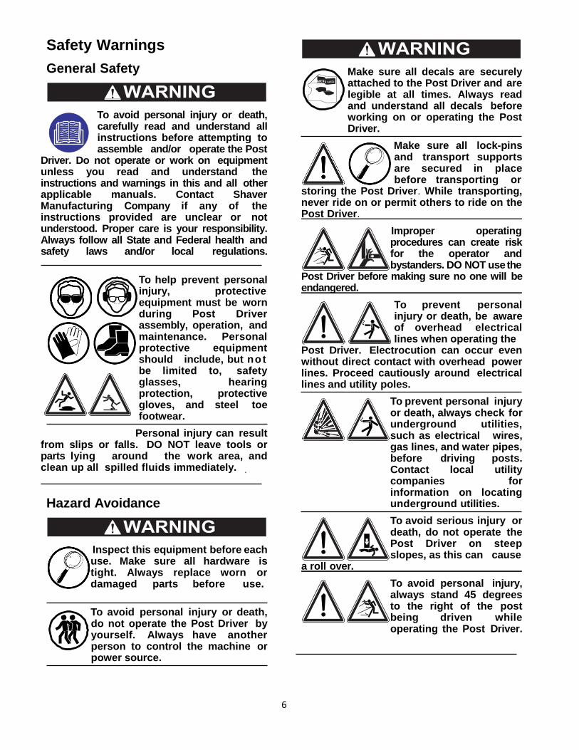
6
Safety Warnings
General Safety
To avoid personal injury or death, carefully read and understand all instructions before attempting to assemble and/or operate the Post
Driver. Do not operate or work on equipment unless you read and understand the instructions and warnings in this and all other applicable manuals. Contact Shaver Manufacturing Company if any of the instructions provided are unclear or not understood. Proper care is your responsibility. Always follow all State and Federal health and safety laws and/or local regulations.
To help prevent personal injury, protective equipment must be worn during Post Driver assembly, operation, and maintenance. Personal protective equipment should include, but not be limited to, safety glasses, hearing protection, protective gloves, and steel toe footwear.
Personal injury can result from slips or falls. DO NOT leave tools or parts lying around the work area, and clean up all spilled fluids immediately.
Hazard Avoidance
Inspect this equipment before each use. Make sure all hardware is tight. Always replace worn or damaged parts before use.
To avoid personal injury or death, do not operate the Post Driver by yourself. Always have another person to control the machine or power source.
Make sure all decals are securely attached to the Post Driver and are legible at all times. Always read and understand all decals before working on or operating the Post Driver.
Make sure all lock-pins and transport supports are secured in place before transporting or
storing the Post Driver. While transporting, never ride on or permit others to ride on the Post Driver.
Improper operating procedures can create risk for the operator and bystanders. DO NOT use the
Post Driver before making sure no one will be endangered.
To prevent personal injury or death, be aware of overhead electrical lines when operating the
Post Driver. Electrocution can occur even without direct contact with overhead power lines. Proceed cautiously around electrical lines and utility poles.
To prevent personal injury or death, always check for underground utilities, such as electrical wires, gas lines, and water pipes, before driving posts. Contact local utility companies for information on locating underground utilities.
To avoid serious injury or death, do not operate the Post Driver on steep slopes, as this can cause
a roll over.
To avoid personal injury, always stand 45 degrees to the right of the post being driven while operating the Post Driver.
AR
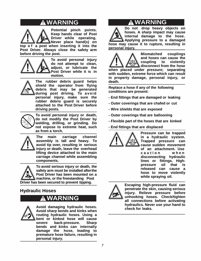
7
Potential pinch points. Keep hands clear of Post Driver while operating. Never place hand(s) on
top o f a post when inserting it into the Post Driver. Always close the safety arm before driving the post.
To avoid personal injury do not attempt to clean, adjust, or lubricate the Post Driver while it is in motion.
The rubber debris guard helps shield the operator from flying debris that may be generated during post driving. To a vo i d personal injury, make sure the rubber debris guard is securely attached to the Post Driver before driving posts.
To avoid personal injury or death, do not modify the Post Driver by welding, drilling, or grinding. Do not expose to extreme heat, such as from a torch.
The main carriage channel assembly is tall and heavy. To avoid tip over, resulting in serious injury or death, leave the overhead lifting device attached to the main carriage channel while assembling components.
To avoid serious injury or death, the safety arm must be installed after the Post Driver has been mounted on a machine, or the freestanding Post
Driver has been secured to prevent tipping.
Hydraulic Hoses
Avoid damaging hydraulic hoses. Avoid sharp bends and kinks when routing hydraulic hoses. Using a bent or kinked hose will cause severe back-pressure. Sharp bends and kinks can internally damage the hose, leading to premature hose failure, resulting in personal injury.
Do not drop heavy objects on hoses. A sharp impact may cause internal damage to the hose. Applying pressure to a damaged
hose may cause it to rupture, resulting in personal injury.
Mismatched couplings and hoses can cause the coupling to violently disconnect from the hose
when placed under pressure; separating with sudden, extreme force which can result in property damage, personal injury, or death.
Replace a hose if any of the following conditions are present:
- End fittings that are damaged or leaking
- Outer coverings that are chafed or cut
- Wire shields that are exposed
- Outer coverings that are ballooning
- Flexible part of the hoses that are kinked
- End fittings that are displaced
Pressure can be trapped in a hydraulic system. Trapped pressure can cause sudden movement of an attachment. Use c a u t i o n w h e n disconnecting hydraulic lines or fittings. High-pressure oil that is released can cause a hose to move violently while spraying oil.
Escaping high-pressure fluid can penetrate the skin, causing serious injury. Relieve pressure before unhooking hoses. Check/tighten all connections before activating hydraulics. Never use your hand to check for leaks.
WARNING WARNING
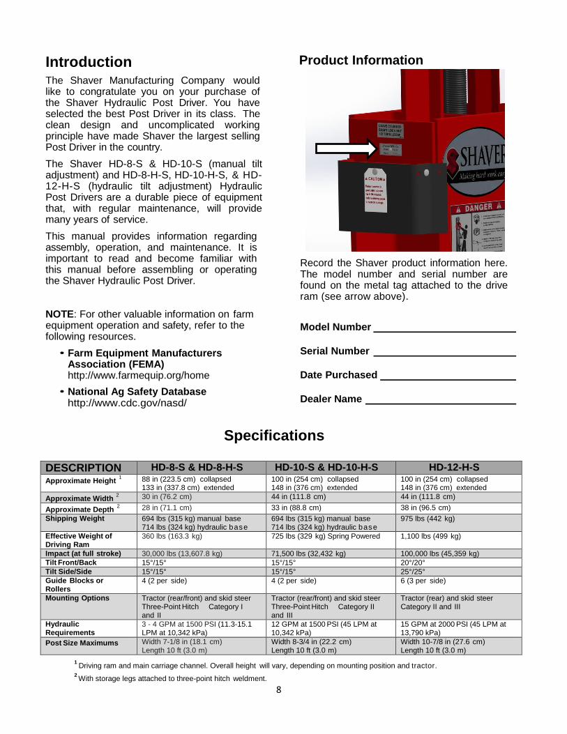
8
Introduction The Shaver Manufacturing Company would like to congratulate you on your purchase of the Shaver Hydraulic Post Driver. You have selected the best Post Driver in its class. The clean design and uncomplicated working principle have made Shaver the largest selling Post Driver in the country.
The Shaver HD-8-S & HD-10-S (manual tilt adjustment) and HD-8-H-S, HD-10-H-S, & HD-12-H-S (hydraulic tilt adjustment) Hydraulic Post Drivers are a durable piece of equipment that, with regular maintenance, will provide many years of service.
This manual provides information regarding assembly, operation, and maintenance. It is important to read and become familiar with this manual before assembling or operating the Shaver Hydraulic Post Driver.
NOTE: For other valuable information on farm equipment operation and safety, refer to the following resources.
• Farm Equipment Manufacturers Association (FEMA) http://www.farmequip.org/home
• National Ag Safety Database http://www.cdc.gov/nasd/
Product Information
Record the Shaver product information here. The model number and serial number are found on the metal tag attached to the drive ram (see arrow above).
Model Number
Serial Number
Date Purchased
Dealer Name
Specifications
DESCRIPTION HD-8-S & HD-8-H-S HD-10-S & HD-10-H-S HD-12-H-S Approximate Height
1 88 in (223.5 cm) collapsed 133 in (337.8 cm) extended
100 in (254 cm) collapsed 148 in (376 cm) extended
100 in (254 cm) collapsed 148 in (376 cm) extended
Approximate Width 2 30 in (76.2 cm) 44 in (111.8 cm) 44 in (111.8 cm)
Approximate Depth 2 28 in (71.1 cm) 33 in (88.8 cm) 38 in (96.5 cm)
Shipping Weight 694 lbs (315 kg) manual base 714 lbs (324 kg) hydraulic base
694 lbs (315 kg) manual base 714 lbs (324 kg) hydraulic base
975 lbs (442 kg)
Effective Weight of Driving Ram
360 lbs (163.3 kg) 725 lbs (329 kg) Spring Powered 1,100 lbs (499 kg)
Impact (at full stroke) 30,000 lbs (13,607.8 kg) 71,500 lbs (32,432 kg) 100,000 lbs (45,359 kg) Tilt Front/Back 15°/15° 15°/15° 20°/20° Tilt Side/Side 15°/15° 15°/15° 25°/25° Guide Blocks or Rollers
4 (2 per side) 4 (2 per side) 6 (3 per side)
Mounting Options Tractor (rear/front) and skid steer Three-Point Hitch Category I and II
Tractor (rear/front) and skid steer Three-Point Hitch Category II and III
Tractor (rear) and skid steer Category II and III
Hydraulic Requirements
3 - 4 GPM at 1500 PSI (11.3-15.1 LPM at 10,342 kPa)
12 GPM at 1500 PSI (45 LPM at 10,342 kPa)
15 GPM at 2000 PSI (45 LPM at 13,790 kPa)
Post Size Maximums Width 7-1/8 in (18.1 cm) Length 10 ft (3.0 m)
Width 8-3/4 in (22.2 cm) Length 10 ft (3.0 m)
Width 10-7/8 in (27.6 cm) Length 10 ft (3.0 m)
1 Driving ram and main carriage channel. Overall height will vary, depending on mounting position and tractor.
2 With storage legs attached to three-point hitch weldment.
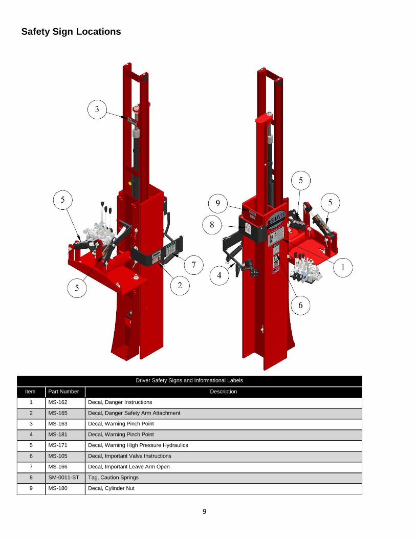
9
Safety Sign Locations
Driver Safety Signs and Informational Labels
Item Part Number Description
1 MS-162 Decal, Danger Instructions
2 MS-165 Decal, Danger Safety Arm Attachment
3 MS-163 Decal, Warning Pinch Point
4 MS-181 Decal, Warning Pinch Point
5 MS-171 Decal, Warning High Pressure Hydraulics
6 MS-105 Decal, Important Valve Instructions
7 MS-166 Decal, Important Leave Arm Open
8 SM-0011-ST Tag, Caution Springs
9 MS-180 Decal, Cylinder Nut
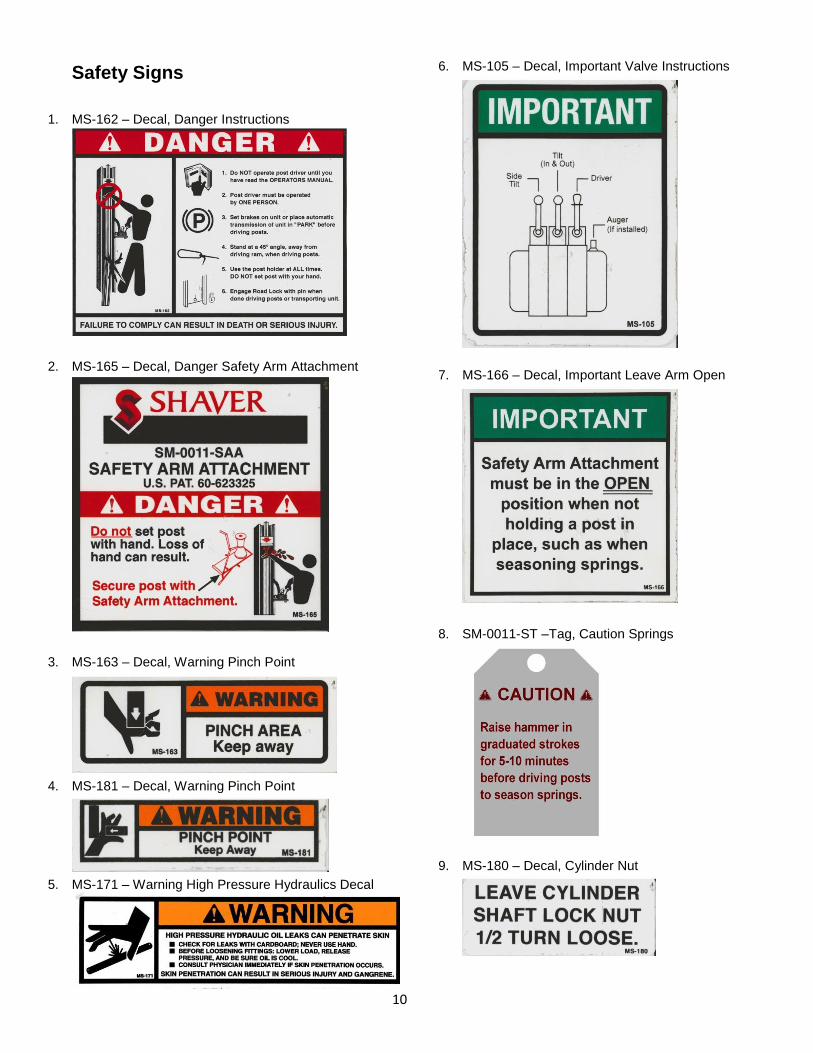
10
Safety Signs
1. MS-162 – Decal, Danger Instructions
2. MS-165 – Decal, Danger Safety Arm Attachment
3. MS-163 – Decal, Warning Pinch Point
4. MS-181 – Decal, Warning Pinch Point
5. MS-171 – Warning High Pressure Hydraulics Decal
6. MS-105 – Decal, Important Valve Instructions
7. MS-166 – Decal, Important Leave Arm Open
8. SM-0011-ST –Tag, Caution Springs
9. MS-180 – Decal, Cylinder Nut
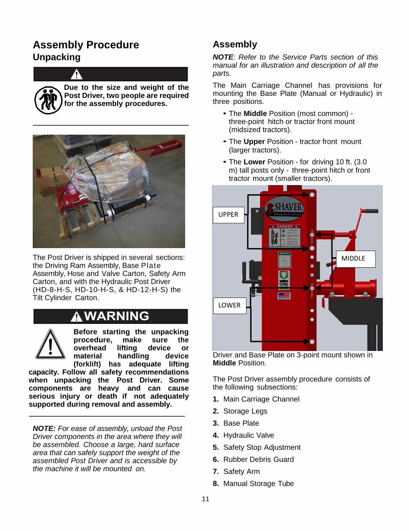
11
Assembly Procedure Unpacking
Due to the size and weight of the Post Driver, two people are required for the assembly procedures.
The Post Driver is shipped in several sections: the Driving Ram Assembly, Base Plate Assembly, Hose and Valve Carton, Safety Arm Carton, and with the Hydraulic Post Driver (HD-8-H-S, HD-10-H-S, & HD-12-H-S) the Tilt Cylinder Carton.
Before starting the unpacking procedure, make sure the overhead lifting device or material handling device (forklift) has adequate lifting
capacity. Follow all safety recommendations when unpacking the Post Driver. Some components are heavy and can cause serious injury or death if not adequately supported during removal and assembly.
NOTE: For ease of assembly, unload the Post Driver components in the area where they will be assembled. Choose a large, hard surface area that can safely support the weight of the assembled Post Driver and is accessible by the machine it will be mounted on.
Assembly
NOTE: Refer to the Service Parts section of this manual for an illustration and description of all the parts.
The Main Carriage Channel has provisions for mounting the Base Plate (Manual or Hydraulic) in three positions.
• The Middle Position (most common) - three-point hitch or tractor front mount (midsized tractors).
• The Upper Position - tractor front mount (larger tractors).
• The Lower Position - for driving 10 ft. (3.0 m) tall posts only - three-point hitch or front tractor mount (smaller tractors).
Driver and Base Plate on 3-point mount shown in Middle Position. The Post Driver assembly procedure consists of the following subsections:
1. Main Carriage Channel
2. Storage Legs
3. Base Plate
4. Hydraulic Valve
5. Safety Stop Adjustment
6. Rubber Debris Guard
7. Safety Arm
8. Manual Storage Tube
UPPER
LOWER
MIDDLE
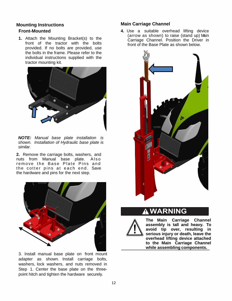
12
Mounting Instructions
Front-Mounted
1. Attach the Mounting Bracket(s) to the front of the tractor with the bolts provided. If no bolts are provided, use the bolts in the frame. Please refer to the individual instructions supplied with the tractor mounting kit.
NOTE: Manual base plate installation is shown. Installation of Hydraulic base plate is similar.
2. Remove the carriage bolts, washers, and nuts from Manual base plate. A l s o r e m o v e t h e B a s e P l a t e P i n s a n d t h e c o t t e r p i n s a t e a c h e n d . Save the hardware and pins for the next step.
3. Install manual base plate on front mount
adapter as shown. Install carriage bolts,
washers, lock washers, and nuts removed in
Step 1. Center the base plate on the three-
point hitch and tighten the hardware securely.
Main Carriage Channel
4. Use a suitable overhead lifting device (arrow as shown) to raise (stand up) Main Carriage Channel. Position the Driver in front of the Base Plate as shown below.
The Main Carriage Channel assembly is tall and heavy. To avoid tip over, resulting in serious injury or death, leave the overhead lifting device attached to the Main Carriage Channel while assembling components.
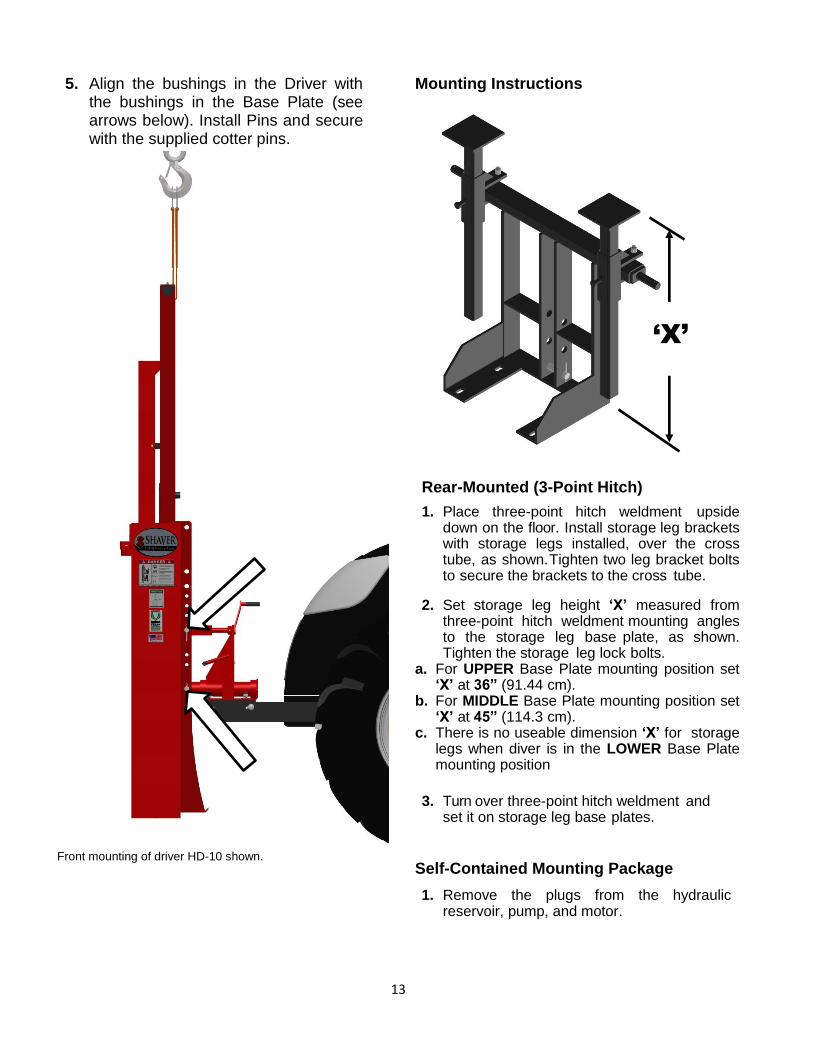
13
5. Align the bushings in the Driver with the bushings in the Base Plate (see arrows below). Install Pins and secure with the supplied cotter pins.
Front mounting of driver HD-10 shown.
Mounting Instructions
Rear-Mounted (3-Point Hitch)
1. Place three-point hitch weldment upside down on the floor. Install storage leg brackets with storage legs installed, over the cross tube, as shown. Tighten two leg bracket bolts to secure the brackets to the cross tube.
2. Set storage leg height ‘X’ measured from three-point hitch weldment mounting angles to the storage leg base plate, as shown. Tighten the storage leg lock bolts.
a. For UPPER Base Plate mounting position set ‘X’ at 36” (91.44 cm).
b. For MIDDLE Base Plate mounting position set ‘X’ at 45” (114.3 cm).
c. There is no useable dimension ‘X’ for storage legs when diver is in the LOWER Base Plate mounting position
3. Turn over three-point hitch weldment and
set it on storage leg base plates.
Self-Contained Mounting Package
1. Remove the plugs from the hydraulic reservoir, pump, and motor.
‘X’
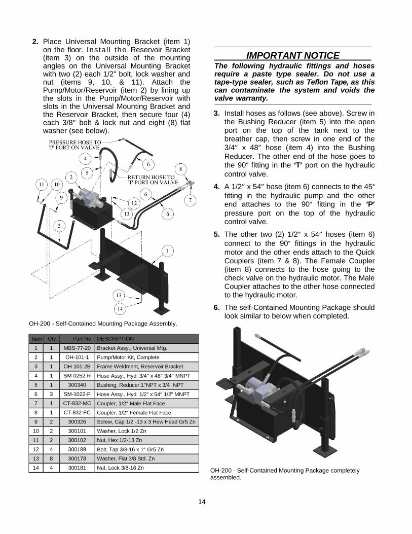
14
2. Place Universal Mounting Bracket (item 1) on the floor. Instal l the Reservoir Bracket (item 3) on the outside of the mounting angles on the Universal Mounting Bracket with two (2) each 1/2" bolt, lock washer and nut (items 9, 10, & 11). Attach the Pump/Motor/Reservoir (item 2) by lining up the slots in the Pump/Motor/Reservoir with slots in the Universal Mounting Bracket and the Reservoir Bracket, then secure four (4) each 3/8” bolt & lock nut and eight (8) flat washer (see below).
OH-200 - Self-Contained Mounting Package Assembly.
Item Qty. Part No. DESCRIPTION
1 1 MBS-77-20 Bracket Assy., Universal Mtg.
2 1 OH-101-1 Pump/Motor Kit, Complete
3 1 OH-101-2B Frame Weldment, Reservoir Bracket
4 1 SM-0252-R Hose Assy., Hyd. 3/4” x 48” 3/4” MNPT
5 1 300340 Bushing, Reducer 1”NPT x 3/4" NPT
6 3 SM-1022-P Hose Assy., Hyd. 1/2" x 54” 1/2" MNPT
7 1 CT-832-MC Coupler, 1/2” Male Flat Face
8 1 CT-832-FC Coupler, 1/2” Female Flat Face
9 2 300326 Screw, Cap 1/2 -13 x 3 Hew Head Gr5 Zn
10 2 300101 Washer, Lock 1/2 Zn
11 2 300102 Nut, Hex 1/2-13 Zn
12 4 300189 Bolt, Tap 3/8-16 x 1” Gr5 Zn
13 8 300178 Washer, Flat 3/8 Std. Zn
14 4 300181 Nut, Lock 3/8-16 Zn
IMPORTANT NOTICE The following hydraulic fittings and hoses require a paste type sealer. Do not use a tape-type sealer, such as Teflon Tape, as this can contaminate the system and voids the valve warranty.
3. Install hoses as follows (see above). Screw in the Bushing Reducer (item 5) into the open port on the top of the tank next to the breather cap, then screw in one end of the 3/4” x 48” hose (item 4) into the Bushing
Reducer. The other end of the hose goes to the 90° fitting in the ‘T’ port on the hydraulic
control valve.
4. A 1/2” x 54” hose (item 6) connects to the 45° fitting in the hydraulic pump and the other end attaches to the 90° fitting in the ‘P’ pressure port on the top of the hydraulic control valve.
5. The other two (2) 1/2” x 54” hoses (item 6)
connect to the 90° fittings in the hydraulic
motor and the other ends attach to the Quick Couplers (item 7 & 8). The Female Coupler (item 8) connects to the hose going to the check valve on the hydraulic motor. The Male Coupler attaches to the other hose connected to the hydraulic motor.
6. The self-Contained Mounting Package should look similar to below when completed.
OH-200 - Self-Contained Mounting Package completely assembled.
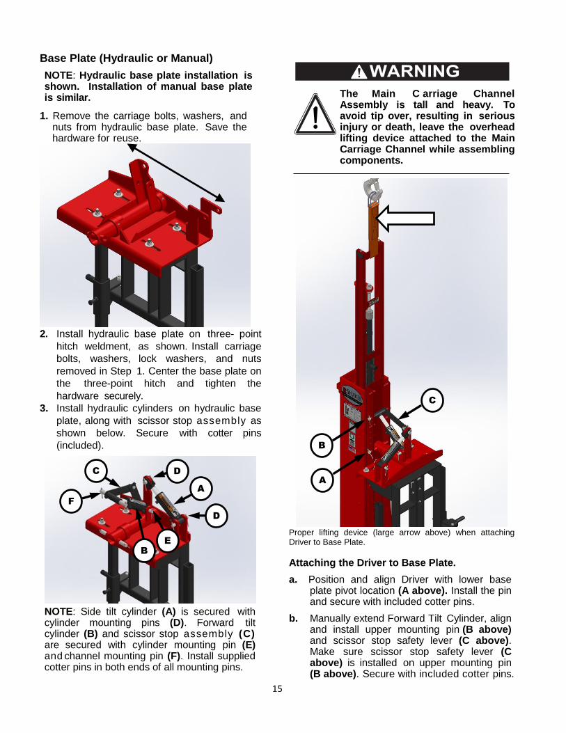
15
Base Plate (Hydraulic or Manual)
NOTE: Hydraulic base plate installation is shown. Installation of manual base plate is similar.
1. Remove the carriage bolts, washers, and nuts from hydraulic base plate. Save the hardware for reuse.
2. Install hydraulic base plate on three- point
hitch weldment, as shown. Install carriage
bolts, washers, lock washers, and nuts
removed in Step 1. Center the base plate on
the three-point hitch and tighten the
hardware securely.
3. Install hydraulic cylinders on hydraulic base
plate, along with scissor stop assembly as
shown below. Secure with cotter pins
(included).
NOTE: Side tilt cylinder (A) is secured with cylinder mounting pins (D). Forward tilt cylinder (B) and scissor stop assembly (C) are secured with cylinder mounting pin (E) and channel mounting pin (F). Install supplied cotter pins in both ends of all mounting pins.
The Main C arriage Channel Assembly is tall and heavy. To avoid tip over, resulting in serious injury or death, leave the overhead lifting device attached to the Main Carriage Channel while assembling components.
Proper lifting device (large arrow above) when attaching Driver to Base Plate.
Attaching the Driver to Base Plate.
a. Position and align Driver with lower base plate pivot location (A above). Install the pin and secure with included cotter pins.
b. Manually extend Forward Tilt Cylinder, align and install upper mounting pin (B above) and scissor stop safety lever (C above). Make sure scissor stop safety lever (C above) is installed on upper mounting pin (B above). Secure with included cotter pins.
A
B
C
D
D
E
F
A
B
C
A
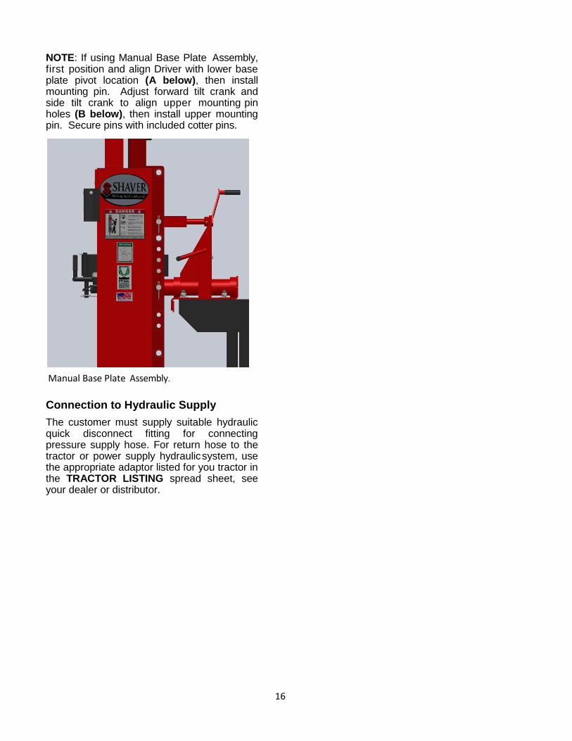
16
NOTE: If using Manual Base Plate Assembly, first position and align Driver with lower base plate pivot location (A below), then install mounting pin. Adjust forward tilt crank and side tilt crank to align upper mounting pin holes (B below), then install upper mounting pin. Secure pins with included cotter pins.
Manual Base Plate Assembly.
Connection to Hydraulic Supply
The customer must supply suitable hydraulic quick disconnect fitting for connecting pressure supply hose. For return hose to the tractor or power supply hydraulic system, use the appropriate adaptor listed for you tractor in the TRACTOR LISTING spread sheet, see your dealer or distributor.
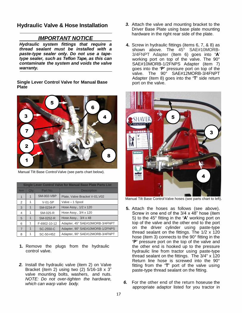
17
Hydraulic Valve & Hose Installation
IMPORTANT NOTICE Hydraulic system fittings that require a thread sealant must be installed with a paste-type sealer only. Do not use a tape-type sealer, such as Teflon Tape, as this can contaminate the system and voids the valve warranty.
Single Lever Control Valve for Manual Base Plate
Manual Tilt Base Control Valve (see parts chart below).
1. Remove the plugs from the hydraulic control valve.
2. Install the hydraulic valve (item 2) on Valve Bracket (item 2) using two (2) 5/16-18 x 3” valve mounting bolts, washers, and nuts. NOTE: Do not over-tighten the hardware, which can warp valve body.
3. Attach the valve and mounting bracket to the Driver Base Plate using base plate mounting hardware in the right rear side of the plate.
4. Screw in hydraulic fittings (items 6, 7, & 8) as shown above. The 45° SAE#10MORB-3/4FNPT Adapter (Item 6) goes into ‘A’ working port on top of the valve. The 90° SAE#10MORB-1/2FNPS Adapter (item 7) goes into the ‘P’ pressure port on top of the valve. The 90° SAE#12MORB-3/4FNPT Adapter (item 8) goes into the ‘T’ side return port on the valve.
Manual Tilt Base Control Valve hoses (see parts chart to left).
5. Attach the hoses as follows (see above). Screw in one end of the 3/4 x 48” hose (item 5) to the 45° fitting in the ‘A’ working port on top of the valve and the other end to the port on the driver cylinder using paste-type thread sealant on the fittings. The 1/2 x 120 hose (item 3) connects to the 90° fitting in the ‘P’ pressure port on the top of the valve and the other end is hooked up to the pressure hydraulic line from tractor using paste-type thread sealant on the fittings. The 3/4" x 120 Return line hose is screwed into the 90° fitting from the ‘T’ port of the valve using paste-type thread sealant on the fitting.
6. For the other end of the return hose use the appropriate adaptor listed for you tractor in
Single Lever Control Valve for Manual Base Plate Parts List
Item Qty. Part No. Description
1 1 SM-002-VBP Plate, Valve Bracket V-01,V02
2 1 V-01-SP Valve – 1 Spool
3 1 SM-0234-P Hose Assy., 1/2 x 120
4 1 SM-025-R Hose Assy., 3/4 x 120
5 1 SM-0252-R Hose Assy., 3/4 x 48
6 1 F-6902-10-12 Adapter, 45° SAE#10MORB-3/4FNPT
7 1 SC-2550-C Adapter, 90° SAE#10MORB-1/2FNPS
8 1 SC-50-H52 Adapter, 90° SAE#12MORB-3/4FNPT
1
6
8
2
3
7
5
4
3
5
4
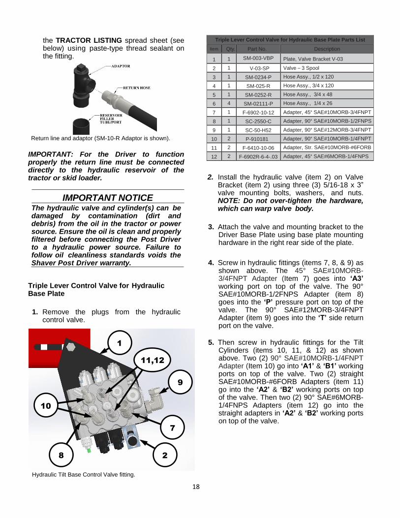
18
the TRACTOR LISTING spread sheet (see below) using paste-type thread sealant on the fitting.
Return line and adaptor (SM-10-R Adaptor is shown).
IMPORTANT: For the Driver to function properly the return line must be connected directly to the hydraulic reservoir of the tractor or skid loader.
IMPORTANT NOTICE
The hydraulic valve and cylinder(s) can be damaged by contamination (dirt and debris) from the oil in the tractor or power source. Ensure the oil is clean and properly filtered before connecting the Post Driver to a hydraulic power source. Failure to follow oil cleanliness standards voids the Shaver Post Driver warranty.
Triple Lever Control Valve for Hydraulic Base Plate
1. Remove the plugs from the hydraulic control valve.
Hydraulic Tilt Base Control Valve fitting.
2. Install the hydraulic valve (item 2) on Valve Bracket (item 2) using three (3) 5/16-18 x 3” valve mounting bolts, washers, and nuts. NOTE: Do not over-tighten the hardware, which can warp valve body.
3. Attach the valve and mounting bracket to the Driver Base Plate using base plate mounting hardware in the right rear side of the plate.
4. Screw in hydraulic fittings (items 7, 8, & 9) as shown above. The 45° SAE#10MORB-3/4FNPT Adapter (Item 7) goes into ‘A3’ working port on top of the valve. The 90° SAE#10MORB-1/2FNPS Adapter (item 8) goes into the ‘P’ pressure port on top of the valve. The 90° SAE#12MORB-3/4FNPT Adapter (item 9) goes into the ‘T’ side return port on the valve.
5. Then screw in hydraulic fittings for the Tilt Cylinders (items 10, 11, & 12) as shown above. Two (2) 90° SAE#10MORB-1/4FNPT Adapter (Item 10) go into ‘A1’ & ‘B1’ working ports on top of the valve. Two (2) straight SAE#10MORB-#6FORB Adapters (item 11) go into the ‘A2’ & ‘B2’ working ports on top of the valve. Then two (2) 90° SAE#6MORB-1/4FNPS Adapters (item 12) go into the straight adapters in ‘A2’ & ‘B2’ working ports on top of the valve.
Triple Lever Control Valve for Hydraulic Base Plate Parts List
Item Qty. Part No. Description
1 1 SM-003-VBP Plate, Valve Bracket V-03
2 1 V-03-SP Valve – 3 Spool
3 1 SM-0234-P Hose Assy., 1/2 x 120
4 1 SM-025-R Hose Assy., 3/4 x 120
5 1 SM-0252-R Hose Assy., 3/4 x 48
6 4 SM-02111-P Hose Assy., 1/4 x 26
7 1 F-6902-10-12 Adapter, 45° SAE#10MORB-3/4FNPT
8 1 SC-2550-C Adapter, 90° SAE#10MORB-1/2FNPS
9 1 SC-50-H52 Adapter, 90° SAE#12MORB-3/4FNPT
10 2 P-910181 Adapter, 90° SAE#10MORB-1/4FNPT
11 2 F-6410-10-06 Adapter, Str. SAE#10MORB-#6FORB
12 2 F-6902R-6-4-.03 Adapter, 45° SAE#6MORB-1/4FNPS
2
8
1
10
9
7
11,12
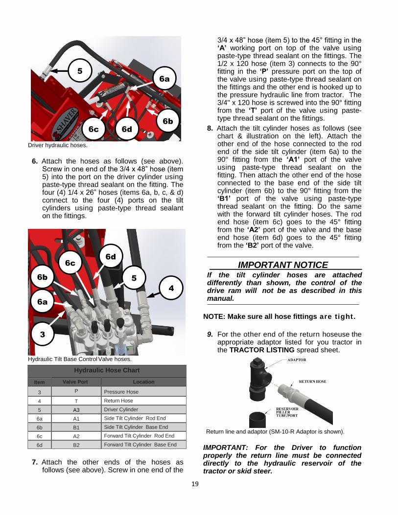
19
Driver hydraulic hoses.
6. Attach the hoses as follows (see above). Screw in one end of the 3/4 x 48” hose (item 5) into the port on the driver cylinder using paste-type thread sealant on the fitting. The four (4) 1/4 x 26” hoses (items 6a, b, c, & d) connect to the four (4) ports on the tilt cylinders using paste-type thread sealant on the fittings.
Hydraulic Tilt Base Control Valve hoses.
7. Attach the other ends of the hoses as follows (see above). Screw in one end of the
3/4 x 48” hose (item 5) to the 45° fitting in the ‘A’ working port on top of the valve using paste-type thread sealant on the fittings. The 1/2 x 120 hose (item 3) connects to the 90° fitting in the ‘P’ pressure port on the top of the valve using paste-type thread sealant on the fittings and the other end is hooked up to the pressure hydraulic line from tractor. The 3/4" x 120 hose is screwed into the 90° fitting from the ‘T’ port of the valve using paste-type thread sealant on the fittings.
8. Attach the tilt cylinder hoses as follows (see chart & illustration on the left). Attach the other end of the hose connected to the rod end of the side tilt cylinder (item 6a) to the 90° fitting from the ‘A1’ port of the valve using paste-type thread sealant on the fitting. Then attach the other end of the hose connected to the base end of the side tilt cylinder (item 6b) to the 90° fitting from the ‘B1’ port of the valve using paste-type thread sealant on the fitting. Do the same with the forward tilt cylinder hoses. The rod end hose (item 6c) goes to the 45° fitting from the ‘A2’ port of the valve and the base end hose (item 6d) goes to the 45° fitting from the ‘B2’ port of the valve.
IMPORTANT NOTICE If the tilt cylinder hoses are attached differently than shown, the control of the drive ram will not be as described in this manual.
NOTE: Make sure all hose fittings are tight.
9. For the other end of the return hose use the appropriate adaptor listed for you tractor in the TRACTOR LISTING spread sheet.
Return line and adaptor (SM-10-R Adaptor is shown).
IMPORTANT: For the Driver to function properly the return line must be connected directly to the hydraulic reservoir of the tractor or skid steer.
Hydraulic Hose Chart
Item Valve Port Location
3 P Pressure Hose
4 T Return Hose
5 A3 Driver Cylinder
6a A1 Side Tilt Cylinder Rod End
6b B1 Side Tilt Cylinder Base End
6c A2 Forward Tilt Cylinder Rod End
6d B2 Forward Tilt Cylinder Base End
5
4
5
6b
6c
6d
6a
3
6a
6b
6c
6d
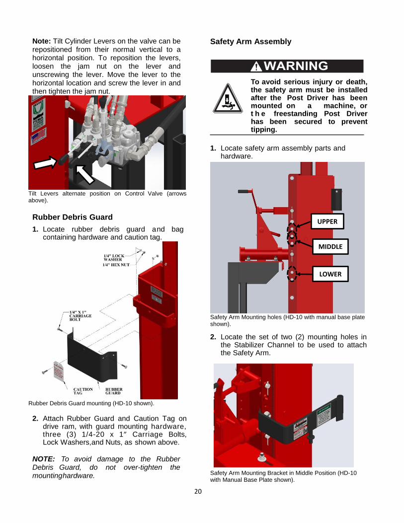
20
Note: Tilt Cylinder Levers on the valve can be repositioned from their normal vertical to a horizontal position. To reposition the levers, loosen the jam nut on the lever and unscrewing the lever. Move the lever to the horizontal location and screw the lever in and then tighten the jam nut.
Tilt Levers alternate position on Control Valve (arrows above).
Rubber Debris Guard
1. Locate rubber debris guard and bag containing hardware and caution tag.
Rubber Debris Guard mounting (HD-10 shown).
2. Attach Rubber Guard and Caution Tag on drive ram, with guard mounting hardware, three (3) 1/4-20 x 1” Carriage Bolts, Lock Washers, and Nuts, as shown above.
NOTE: To avoid damage to the Rubber Debris Guard, do not over-tighten the mounting hardware.
Safety Arm Assembly
To avoid serious injury or death, the safety arm must be installed after the Post Driver has been mounted on a machine, or t h e freestanding Post Driver has been secured to prevent tipping.
1. Locate safety arm assembly parts and
hardware.
Safety Arm Mounting holes (HD-10 with manual base plate shown).
2. Locate the set of two (2) mounting holes in the Stabilizer Channel to be used to attach the Safety Arm.
Safety Arm Mounting Bracket in Middle Position (HD-10 with Manual Base Plate shown).
UPPER
MIDDLE
LOWER
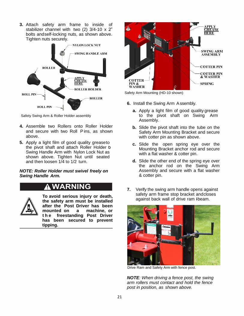
21
3. Attach safety arm frame to inside of stabilizer channel with two (2) 3/4-10 x 2” bolts and self-locking nuts, as shown above. Tighten nuts securely.
Safety Swing Arm & Roller Holder assembly
4. Assemble two Rollers onto Roller Holder and secure with two Roll P ins, as shown above.
5. Apply a light film of good quality grease to the pivot shaft and attach Roller Holder to Swing Handle Arm with Nylon Lock Nut as shown above. Tighten Nut until seated and then loosen 1/4 to 1/2 turn.
NOTE: Roller Holder must swivel freely on Swing Handle Arm.
To avoid serious injury or death, the safety arm must be installed after the Post Driver has been mounted on a machine, or t h e freestanding Post Driver has been secured to prevent tipping.
Safety Arm Mounting (HD-10 shown)
6. Install the Swing Arm Assembly.
a. Apply a light film of good quality grease to the pivot shaft on Swing Arm Assembly.
b. Slide the pivot shaft into the tube on the Safety Arm Mounting Bracket and secure with cotter pin as shown above.
c. Slide the open spring eye over the Mounting Bracket anchor rod and secure with a flat washer & cotter pin.
d. Slide the other end of the spring eye over the anchor rod on the Swing Arm Assembly and secure with a flat washer & cotter pin.
7. Verify the swing arm handle opens against safety arm frame stop bracket and closes against back wall of drive ram I-beam.
Drive Ram and Safety Arm with fence post.
NOTE: When driving a fence post, the swing arm rollers must contact and hold the fence post in position, as shown above.
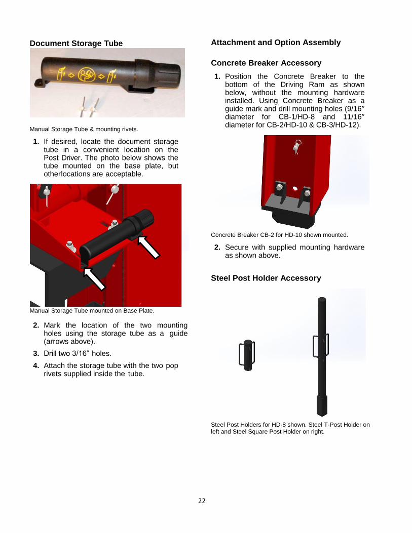
22
Document Storage Tube
Manual Storage Tube & mounting rivets.
1. If desired, locate the document storage tube in a convenient location on the Post Driver. The photo below shows the tube mounted on the base plate, but other locations are acceptable.
Manual Storage Tube mounted on Base Plate.
2. Mark the location of the two mounting holes using the storage tube as a guide (arrows above).
3. Drill two 3/16” holes.
4. Attach the storage tube with the two pop rivets supplied inside the tube.
Attachment and Option Assembly
Concrete Breaker Accessory
1. Position the Concrete Breaker to the bottom of the Driving Ram as shown below, without the mounting hardware installed. Using Concrete Breaker as a guide mark and drill mounting holes (9/16” diameter for CB-1/HD-8 and 11/16” diameter for CB-2/HD-10 & CB-3/HD-12).
Concrete Breaker CB-2 for HD-10 shown mounted.
2. Secure with supplied mounting hardware as shown above.
Steel Post Holder Accessory
Steel Post Holders for HD-8 shown. Steel T-Post Holder on left and Steel Square Post Holder on right.
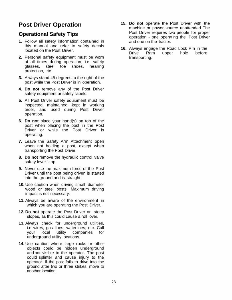
23
Post Driver Operation
Operational Safety Tips
1. Follow all safety information contained in this manual and refer to safety decals located on the Post Driver.
2. Personal safety equipment must be worn at all times during operation, i.e. safety glasses, steel toe shoes, hearing protection, etc.
3. Always stand 45 degrees to the right of the post while the Post Driver is in operation.
4. Do not remove any of the Post Driver safety equipment or safety labels.
5. All Post Driver safety equipment must be inspected, maintained, kept in working order, and used during Post Driver operation.
6. Do not place your hand(s) on top of the post when placing the post in the Post Driver or while the Post Driver is operating.
7. Leave the Safety Arm Attachment open when not holding a post, except when transporting the Post Driver.
8. Do not remove the hydraulic control valve safety lever stop.
9. Never use the maximum force of the Post Driver until the post being driven is started into the ground and is straight.
10. Use caution when driving small diameter wood or steel posts. Maximum driving impact is not necessary.
11. Always be aware of the environment in which you are operating the Post Driver.
12. Do not operate the Post Driver on steep slopes, as this could cause a roll over.
13. Always check for underground utilities, i.e. wires, gas lines, waterlines, etc. Call your local utility companies for underground utility locations.
14. Use caution where large rocks or other objects could be hidden underground and not visible to the operator. The post could splinter and cause injury to the operator. If the post fails to drive into the ground after two or three strikes, move to another location.
15. Do not operate the Post Driver with the machine or power source unattended. The Post Driver requires two people for proper operation - one operating the Post Driver and one on the tractor.
16. Always engage the Road Lock Pin in the Drive Ram upper hole before transporting.
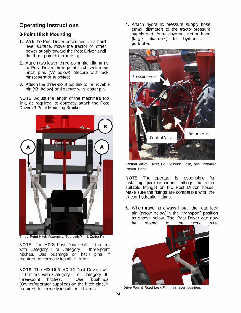
24
Operating Instructions
3-Point Hitch Mounting
1. With the Post Driver positioned on a hard level surface, move the tractor or other power supply toward the Post Driver until the three-point hitch lines up.
2. Attach two lower, three-point hitch lift arms to Post Driver three-point hitch weldment hitch pins (‘A’ below). Secure with lock pins (operator supplied).
3. Attach the three-point top link to removable pin (‘B’ below) and secure with cotter pin.
NOTE: Adjust the length of the machine’s top link, as required, to correctly attach the Post Drivers 3-Point Mounting Bracket.
Three-Point Hitch Assembly, Top Link Pin, & Cotter Pin.
NOTE: The HD-8 Post Driver will fit tractors with Category I or Category II three-point hitches. Use bushings on hitch pins, if required, to correctly install lift arms.
NOTE: The HD-10 & HD-12 Post Drivers will fit tractors with Category II or Category III three-point hitches. Use bushings (Owner/operator supplied) on the hitch pins, if required, to correctly install the lift arms.
4. Attach hydraulic pressure supply hose (small diameter) to the tractor pressure supply port. Attach hydraulic return hose (larger diameter) to hydraulic fill port/tube.
Control Valve, Hydraulic Pressure Hose, and Hydraulic
Return Hose.
NOTE: The operator is responsible for installing quick-disconnect fittings (or other suitable fittings) on the Post Driver hoses. Make sure the fittings are compatible with the tractor hydraulic fittings.
5. When traveling always install the road lock pin (arrow below) in the “transport” position as shown below. The Post Driver can now be moved to the work site.
Drive Ram & Road Lock Pin in transport position.
A
A
B
Pressure Hose
Return Hose Control Valve
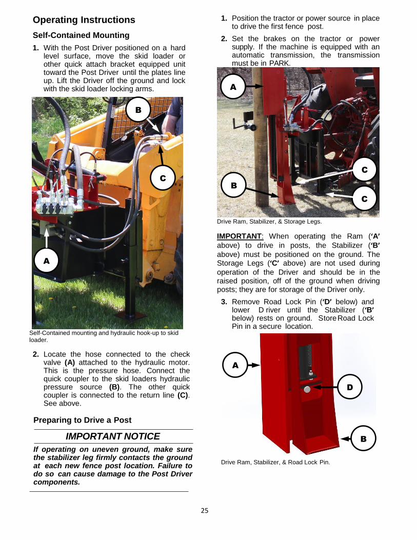
25
Operating Instructions
Self-Contained Mounting
1. With the Post Driver positioned on a hard level surface, move the skid loader or other quick attach bracket equipped unit toward the Post Driver until the plates line up. Lift the Driver off the ground and lock with the skid loader locking arms.
Self-Contained mounting and hydraulic hook-up to skid loader.
2. Locate the hose connected to the check valve (A) attached to the hydraulic motor. This is the pressure hose. Connect the quick coupler to the skid loaders hydraulic pressure source (B). The other quick coupler is connected to the return line (C). See above.
Preparing to Drive a Post
IMPORTANT NOTICE
If operating on uneven ground, make sure the stabilizer leg firmly contacts the ground at each new fence post location. Failure to do so can cause damage to the Post Driver components.
1. Position the tractor or power source in place to drive the first fence post.
2. Set the brakes on the tractor or power supply. If the machine is equipped with an automatic transmission, the transmission must be in PARK.
Drive Ram, Stabilizer, & Storage Legs.
IMPORTANT: When operating the Ram (‘A’ above) to drive in posts, the Stabilizer (‘B’ above) must be positioned on the ground. The Storage Legs (‘C’ above) are not used during
operation of the Driver and should be in the raised position, off of the ground when driving posts; they are for storage of the Driver only.
3. Remove Road Lock Pin (‘D’ below) and lower D river until the Stabilizer (‘B’ below) rests on ground. Store Road Lock Pin in a secure location.
Drive Ram, Stabilizer, & Road Lock Pin.
C
B
C
A
A
B
D
A
B
C
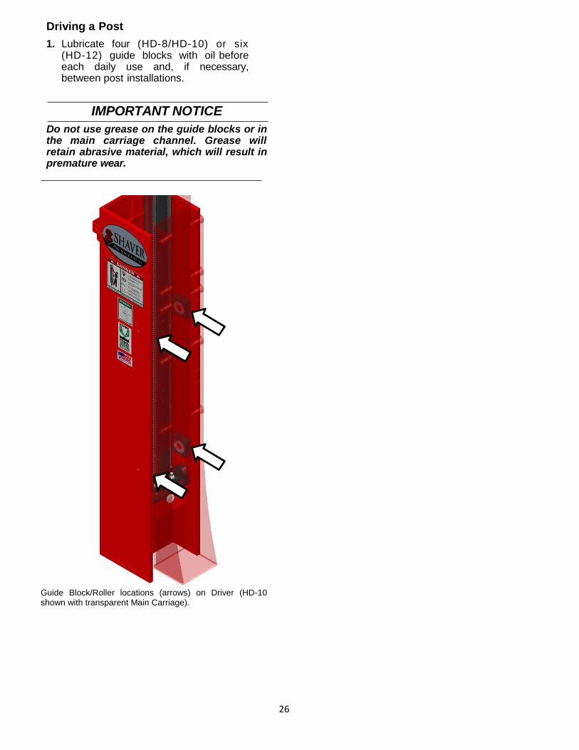
26
Driving a Post
1. Lubricate four (HD-8/HD-10) or six (HD-12) guide blocks with oil before each daily use and, if necessary, between post installations.
IMPORTANT NOTICE
Do not use grease on the guide blocks or in the main carriage channel. Grease will retain abrasive material, which will result in premature wear.
Guide Block/Roller locations (arrows) on Driver (HD-10 shown with transparent Main Carriage).
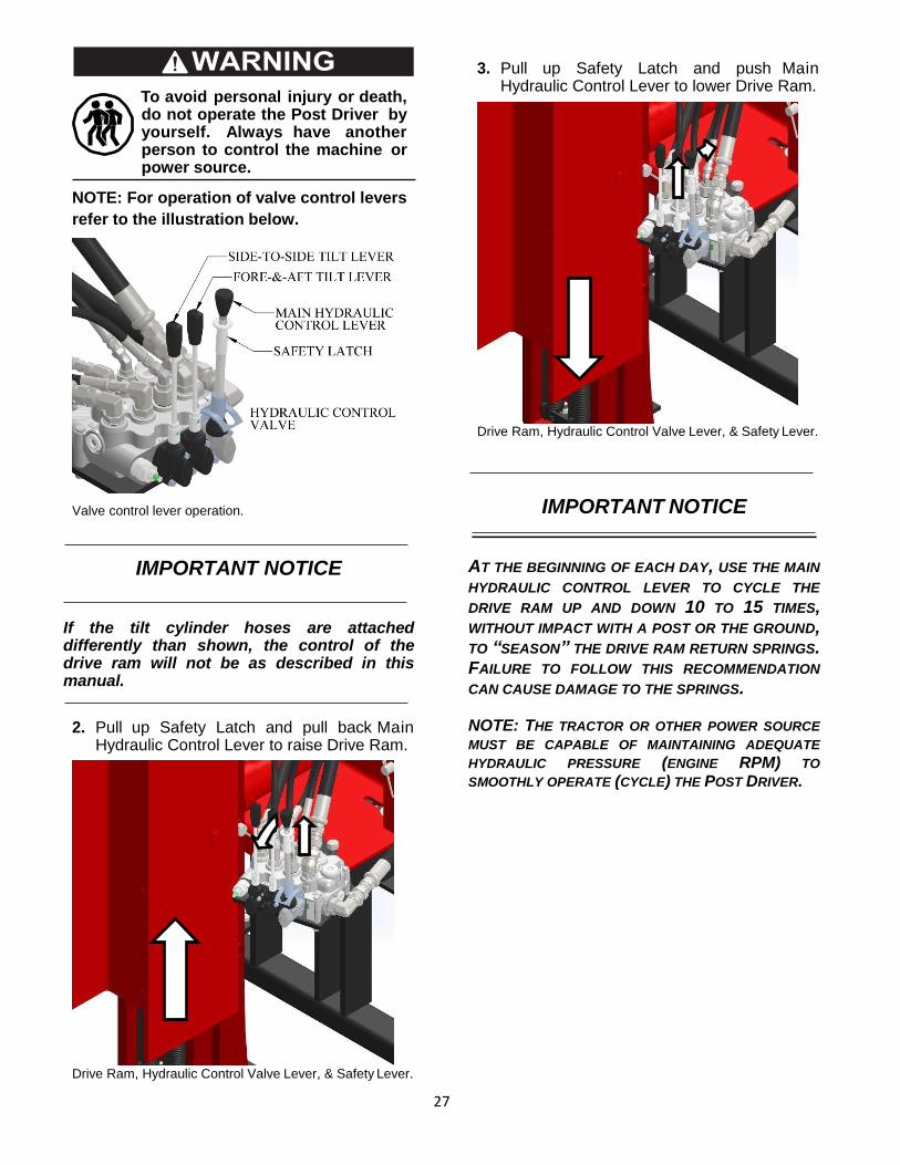
27
To avoid personal injury or death, do not operate the Post Driver by yourself. Always have another person to control the machine or power source.
NOTE: For operation of valve control levers
refer to the illustration below.
Valve control lever operation.
IMPORTANT NOTICE
If the tilt cylinder hoses are attached differently than shown, the control of the drive ram will not be as described in this manual.
2. Pull up Safety Latch and pull back Main Hydraulic Control Lever to raise Drive Ram.
Drive Ram, Hydraulic Control Valve Lever, & Safety Lever.
3. Pull up Safety Latch and push Main Hydraulic Control Lever to lower Drive Ram.
Drive Ram, Hydraulic Control Valve Lever, & Safety Lever.
IMPORTANT NOTICE
AT THE BEGINNING OF EACH DAY, USE THE MAIN
HYDRAULIC CONTROL LEVER TO CYCLE THE
DRIVE RAM UP AND DOWN 10 TO 15 TIMES, WITHOUT IMPACT WITH A POST OR THE GROUND, TO “SEASON” THE DRIVE RAM RETURN SPRINGS. FAILURE TO FOLLOW THIS RECOMMENDATION
CAN CAUSE DAMAGE TO THE SPRINGS.
NOTE: THE TRACTOR OR OTHER POWER SOURCE
MUST BE CAPABLE OF MAINTAINING ADEQUATE
HYDRAULIC PRESSURE (ENGINE RPM) TO
SMOOTHLY OPERATE (CYCLE) THE POST DRIVER.
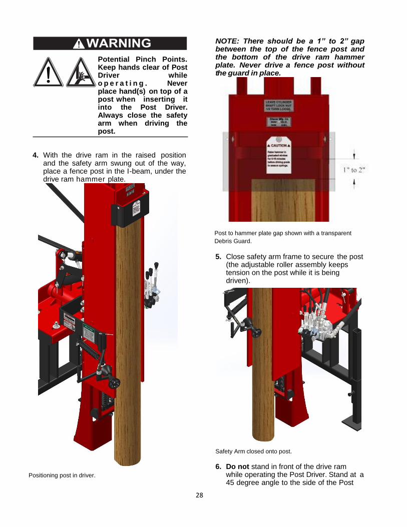
28
Potential Pinch Points. Keep hands clear of Post Driver while o p e r a t i n g . Never place hand(s) on top of a post when inserting it into the Post Driver. Always close the safety arm when driving the post.
4. With the drive ram in the raised position and the safety arm swung out of the way, place a fence post in the I-beam, under the drive ram hammer plate.
Positioning post in driver.
NOTE: There should be a 1” to 2” gap between the top of the fence post and the bottom of the drive ram hammer plate. Never drive a fence post without the guard in place.
Post to hammer plate gap shown with a transparent
Debris Guard.
5. Close safety arm frame to secure the post (the adjustable roller assembly keeps tension on the post while it is being driven).
Safety Arm closed onto post.
6. Do not stand in front of the drive ram while operating the Post Driver. Stand at a 45 degree angle to the side of the Post
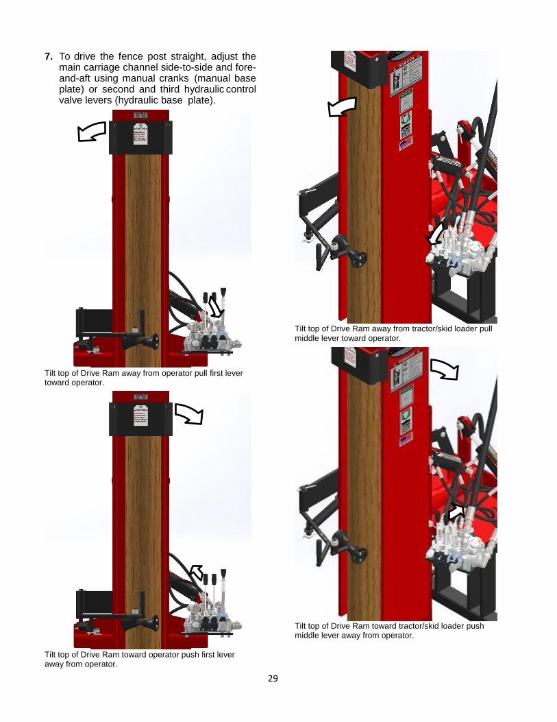
29
7. To drive the fence post straight, adjust the main carriage channel side-to-side and fore-and-aft using manual cranks (manual base plate) or second and third hydraulic control valve levers (hydraulic base plate).
Tilt top of Drive Ram away from operator pull first lever toward operator.
Tilt top of Drive Ram toward operator push first lever away from operator.
Tilt top of Drive Ram away from tractor/skid loader pull middle lever toward operator.
Tilt top of Drive Ram toward tractor/skid loader push middle lever away from operator.
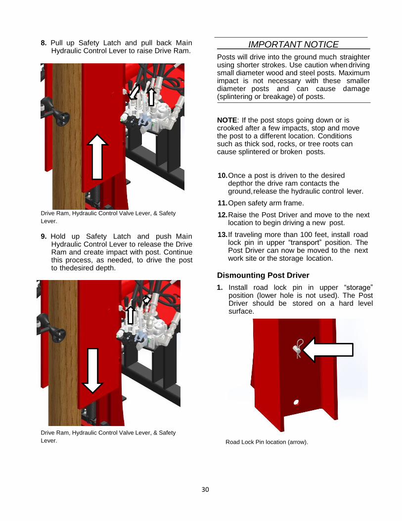
30
8. Pull up Safety Latch and pull back Main Hydraulic Control Lever to raise Drive Ram.
Drive Ram, Hydraulic Control Valve Lever, & Safety
Lever.
9. Hold up Safety Latch and push Main Hydraulic Control Lever to release the Drive Ram and create impact with post. Continue this process, as needed, to drive the post to the desired depth.
Drive Ram, Hydraulic Control Valve Lever, & Safety
Lever.
IMPORTANT NOTICE
Posts will drive into the ground much straighter using shorter strokes. Use caution when driving small diameter wood and steel posts. Maximum impact is not necessary with these smaller diameter posts and can cause damage (splintering or breakage) of posts.
NOTE: If the post stops going down or is crooked after a few impacts, stop and move the post to a different location. Conditions such as thick sod, rocks, or tree roots can cause splintered or broken posts.
10. Once a post is driven to the desired depth or the drive ram contacts the ground, release the hydraulic control lever.
11. Open safety arm frame.
12. Raise the Post Driver and move to the next location to begin driving a new post.
13. If traveling more than 100 feet, install road lock pin in upper “transport” position. The Post Driver can now be moved to the next work site or the storage location.
Dismounting Post Driver
1. Install road lock pin in upper “storage” position (lower hole is not used). The Post Driver should be stored on a hard level surface.
Road Lock Pin location (arrow).
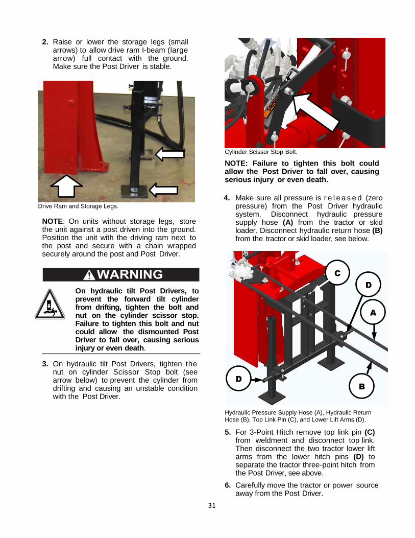
31
2. Raise or lower the storage legs (small arrows) to allow drive ram I-beam (large arrow) full contact with the ground. Make sure the Post Driver is stable.
Drive Ram and Storage Legs.
NOTE: On units without storage legs, store the unit against a post driven into the ground. Position the unit with the driving ram next to the post and secure with a chain wrapped securely around the post and Post Driver.
On hydraulic tilt Post Drivers, to prevent the forward tilt cylinder from drifting, tighten the bolt and nut on the cylinder scissor stop. Failure to tighten this bolt and nut could allow the dismounted Post Driver to fall over, causing serious injury or even death.
3. On hydraulic tilt Post Drivers, tighten the nut on cylinder Scissor Stop bolt (see arrow below) to prevent the cylinder from drifting and causing an unstable condition with the Post Driver.
Cylinder Scissor Stop Bolt.
NOTE: Failure to tighten this bolt could allow the Post Driver to fall over, causing serious injury or even death.
4. Make sure all pressure is r e l e a s e d (zero pressure) from the Post Driver hydraulic system. Disconnect hydraulic pressure supply hose (A) from the tractor or skid loader. Disconnect hydraulic return hose (B) from the tractor or skid loader, see below.
Hydraulic Pressure Supply Hose (A), Hydraulic Return Hose (B), Top Link Pin (C), and Lower Lift Arms (D).
5. For 3-Point Hitch remove top link pin (C) from weldment and disconnect top link. Then disconnect the two tractor lower lift arms from the lower hitch pins (D) to separate the tractor three-point hitch from the Post Driver, see above.
6. Carefully move the tractor or power source away from the Post Driver.
A
B
D
D
C
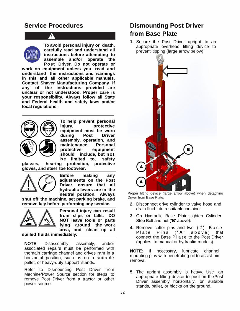
32
Service Procedures
To avoid personal injury or death, carefully read and understand all instructions before attempting to assemble and/or operate the Post Driver. Do not operate or
work on equipment unless you read and understand the instructions and warnings in this and all other applicable manuals. Contact Shaver Manufacturing Company if any of the instructions provided are unclear or not understood. Proper care is your responsibility. Always follow all State and Federal health and safety laws and/or local regulations.
To help prevent personal injury, protective equipment must be worn during Post Driver assembly, operation, and maintenance. Personal protective equipment should include, but not be limited to, safety
glasses, hearing protection, protective gloves, and steel toe footwear.
Before making any adjustments on the Post Driver, ensure that all hydraulic levers are in the neutral position. Always
shut off the machine, set parking brake, and remove key before performing any service.
Personal injury can result from slips or falls. DO NOT leave tools or parts lying around the work area, and clean up all
spilled fluids immediately.
NOTE: Disassembly, assembly, and/or associated repairs must be performed with the main carriage channel and drives ram in a horizontal position, such as on a suitable pallet, or heavy-duty support stands.
Refer to Dismounting Post Driver from Machine/Power Source section for steps to remove Post Driver from a tractor or other power source.
Dismounting Post Driver
from Base Plate
1. Secure the Post Driver upright to an appropriate overhead lifting device to prevent tipping (large arrow below).
Proper lifting device (large arrow above) when detaching Driver from Base Plate.
2. Disconnect drive cylinder to valve hose and drain fluid into a suitable container.
3. On Hydraulic Base Plate tighten Cylinder Stop Bolt and nut (‘B’ above).
4. Remove cotter pins and two ( 2 ) B a s e P l a t e P i n s ( ‘ A ’ a b o v e ) that connect the Base P l a t e to the Post Driver (applies to manual or hydraulic models).
NOTE: If necessary, lubricate channel mounting pins with penetrating oil to assist pin removal.
5. The upright assembly is heavy. Use an appropriate lifting device to position the Post Driver assembly horizontally, on suitable stands, pallet, or blocks on the ground.
A
A
B
A
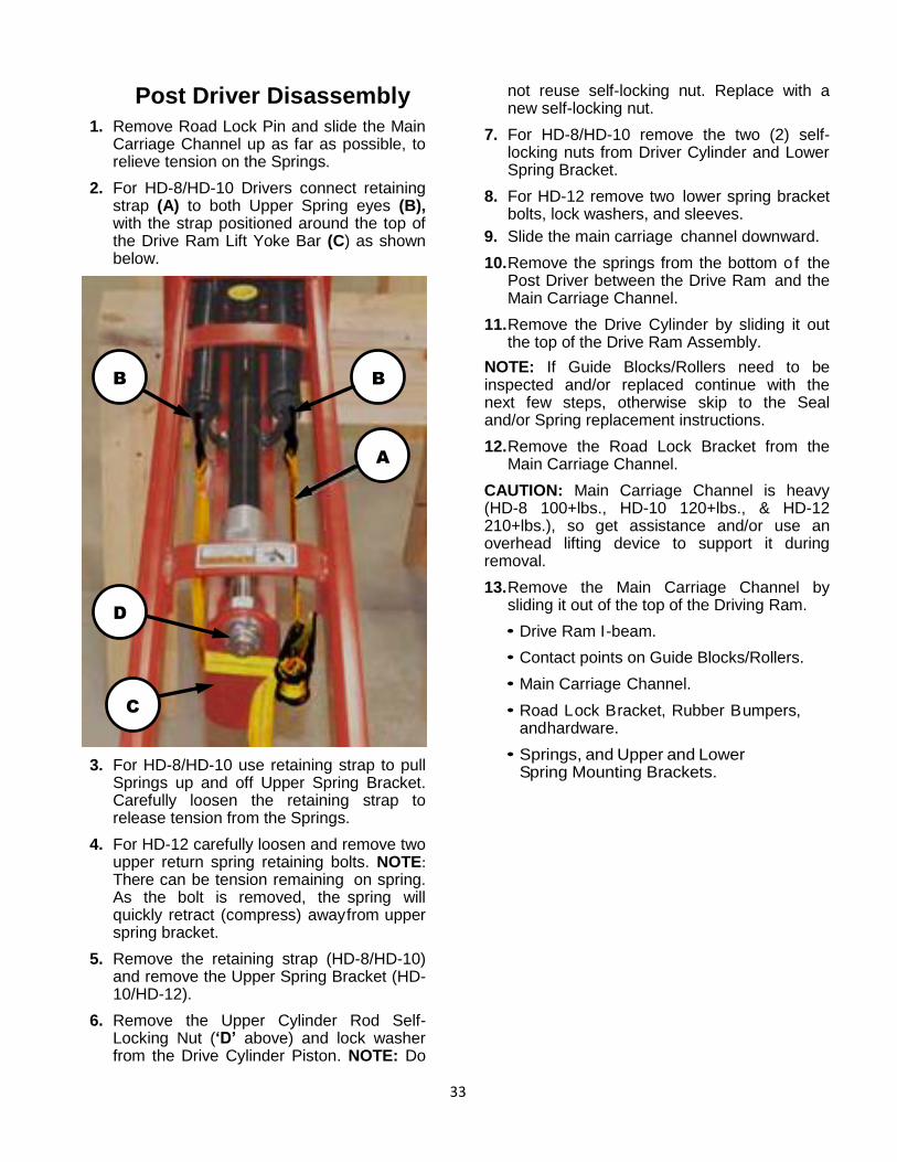
33
Post Driver Disassembly
1. Remove Road Lock Pin and slide the Main Carriage Channel up as far as possible, to relieve tension on the Springs.
2. For HD-8/HD-10 Drivers connect retaining strap (A) to both Upper Spring eyes (B), with the strap positioned around the top of the Drive Ram Lift Yoke Bar (C) as shown below.
3. For HD-8/HD-10 use retaining strap to pull Springs up and off Upper Spring Bracket. Carefully loosen the retaining strap to release tension from the Springs.
4. For HD-12 carefully loosen and remove two upper return spring retaining bolts. NOTE: There can be tension remaining on spring. As the bolt is removed, the spring will quickly retract (compress) away from upper spring bracket.
5. Remove the retaining strap (HD-8/HD-10) and remove the Upper Spring Bracket (HD-10/HD-12).
6. Remove the Upper Cylinder Rod Self-Locking Nut (‘D’ above) and lock washer from the Drive Cylinder Piston. NOTE: Do
not reuse self-locking nut. Replace with a new self-locking nut.
7. For HD-8/HD-10 remove the two (2) self-locking nuts from Driver Cylinder and Lower Spring Bracket.
8. For HD-12 remove two lower spring bracket bolts, lock washers, and sleeves.
9. Slide the main carriage channel downward.
10. Remove the springs from the bottom of the Post Driver between the Drive Ram and the Main Carriage Channel.
11. Remove the Drive Cylinder by sliding it out the top of the Drive Ram Assembly.
NOTE: If Guide Blocks/Rollers need to be inspected and/or replaced continue with the next few steps, otherwise skip to the Seal and/or Spring replacement instructions.
12. Remove the Road Lock Bracket from the Main Carriage Channel.
CAUTION: Main Carriage Channel is heavy (HD-8 100+lbs., HD-10 120+lbs., & HD-12 210+lbs.), so get assistance and/or use an overhead lifting device to support it during removal.
13. Remove the Main Carriage Channel by sliding it out of the top of the Driving Ram.
• Drive Ram I-beam.
• Contact points on Guide Blocks/Rollers.
• Main Carriage Channel.
• Road Lock Bracket, Rubber Bumpers, and hardware.
• Springs, and Upper and Lower Spring Mounting Brackets.
A
B
B
C
A
D
A
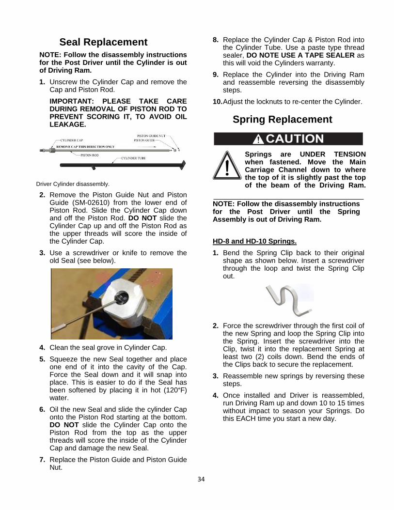
34
Seal Replacement NOTE: Follow the disassembly instructions for the Post Driver until the Cylinder is out of Driving Ram.
1. Unscrew the Cylinder Cap and remove the Cap and Piston Rod.
IMPORTANT: PLEASE TAKE CARE DURING REMOVAL OF PISTON ROD TO PREVENT SCORING IT, TO AVOID OIL LEAKAGE.
Driver Cylinder disassembly.
2. Remove the Piston Guide Nut and Piston Guide (SM-02610) from the lower end of Piston Rod. Slide the Cylinder Cap down and off the Piston Rod. DO NOT slide the Cylinder Cap up and off the Piston Rod as the upper threads will score the inside of the Cylinder Cap.
3. Use a screwdriver or knife to remove the old Seal (see below).
4. Clean the seal grove in Cylinder Cap.
5. Squeeze the new Seal together and place one end of it into the cavity of the Cap. Force the Seal down and it will snap into place. This is easier to do if the Seal has been softened by placing it in hot (120°F) water.
6. Oil the new Seal and slide the cylinder Cap onto the Piston Rod starting at the bottom. DO NOT slide the Cylinder Cap onto the Piston Rod from the top as the upper threads will score the inside of the Cylinder Cap and damage the new Seal.
7. Replace the Piston Guide and Piston Guide Nut.
8. Replace the Cylinder Cap & Piston Rod into the Cylinder Tube. Use a paste type thread sealer, DO NOTE USE A TAPE SEALER as this will void the Cylinders warranty.
9. Replace the Cylinder into the Driving Ram and reassemble reversing the disassembly steps.
10. Adjust the locknuts to re-center the Cylinder.
Spring Replacement
Springs are UNDER TENSION when fastened. Move the Main Carriage Channel down to where the top of it is slightly past the top of the beam of the Driving Ram.
NOTE: Follow the disassembly instructions for the Post Driver until the Spring Assembly is out of Driving Ram.
HD-8 and HD-10 Springs.
1. Bend the Spring Clip back to their original shape as shown below. Insert a screwdriver through the loop and twist the Spring Clip out.
2. Force the screwdriver through the first coil of the new Spring and loop the Spring Clip into the Spring. Insert the screwdriver into the Clip, twist it into the replacement Spring at least two (2) coils down. Bend the ends of the Clips back to secure the replacement.
3. Reassemble new springs by reversing these steps.
4. Once installed and Driver is reassembled, run Driving Ram up and down 10 to 15 times without impact to season your Springs. Do this EACH time you start a new day.
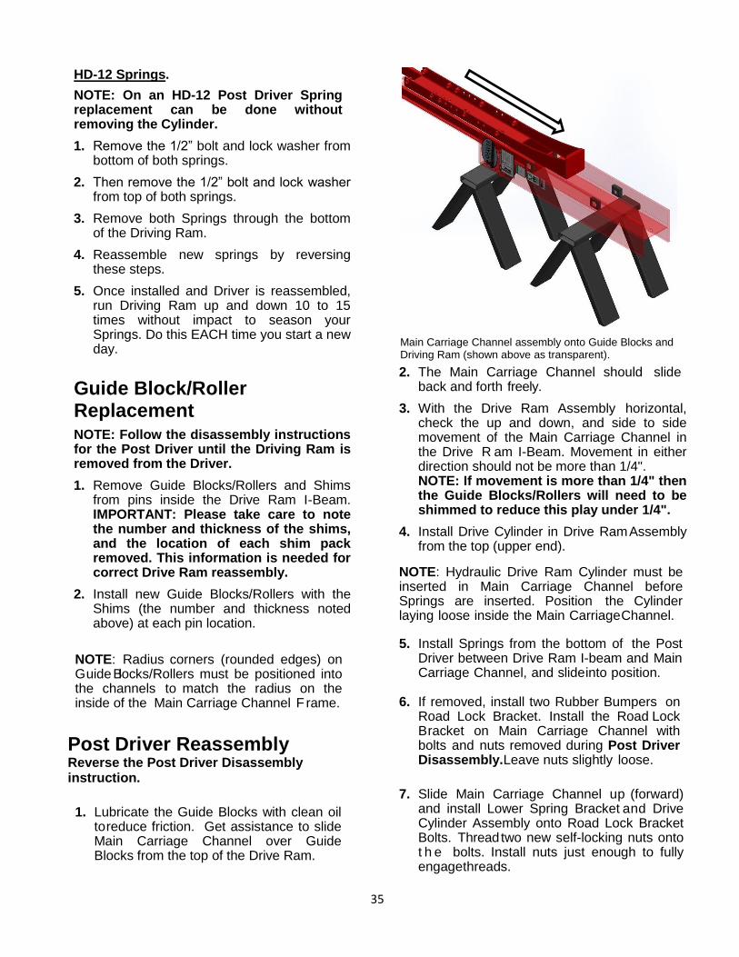
35
HD-12 Springs.
NOTE: On an HD-12 Post Driver Spring replacement can be done without removing the Cylinder.
1. Remove the 1/2” bolt and lock washer from bottom of both springs.
2. Then remove the 1/2” bolt and lock washer from top of both springs.
3. Remove both Springs through the bottom of the Driving Ram.
4. Reassemble new springs by reversing these steps.
5. Once installed and Driver is reassembled, run Driving Ram up and down 10 to 15 times without impact to season your Springs. Do this EACH time you start a new day.
Guide Block/Roller Replacement NOTE: Follow the disassembly instructions for the Post Driver until the Driving Ram is removed from the Driver.
1. Remove Guide Blocks/Rollers and Shims from pins inside the Drive Ram I-Beam. IMPORTANT: Please take care to note the number and thickness of the shims, and the location of each shim pack removed. This information is needed for correct Drive Ram reassembly.
2. Install new Guide Blocks/Rollers with the Shims (the number and thickness noted above) at each pin location.
NOTE: Radius corners (rounded edges) on Guide Blocks/Rollers must be positioned into the channels to match the radius on the inside of the Main Carriage Channel F rame.
Post Driver Reassembly Reverse the Post Driver Disassembly instruction.
1. Lubricate the Guide Blocks with clean oil
to reduce friction. Get assistance to slide Main Carriage Channel over Guide Blocks from the top of the Drive Ram.
Main Carriage Channel assembly onto Guide Blocks and Driving Ram (shown above as transparent).
2. The Main Carriage Channel should slide back and forth freely.
3. With the Drive Ram Assembly horizontal, check the up and down, and side to side movement of the Main Carriage Channel in the Drive R am I-Beam. Movement in either direction should not be more than 1/4". NOTE: If movement is more than 1/4" then the Guide Blocks/Rollers will need to be shimmed to reduce this play under 1/4".
4. Install Drive Cylinder in Drive Ram Assembly from the top (upper end).
NOTE: Hydraulic Drive Ram Cylinder must be inserted in Main Carriage Channel before Springs are inserted. Position the Cylinder laying loose inside the Main Carriage Channel.
5. Install Springs from the bottom of the Post Driver between Drive Ram I-beam and Main Carriage Channel, and slide into position.
6. If removed, install two Rubber Bumpers on Road Lock Bracket. Install the Road Lock Bracket on Main Carriage Channel with bolts and nuts removed during Post Driver Disassembly. Leave nuts slightly loose.
7. Slide Main Carriage Channel up (forward) and install Lower Spring Bracket and Drive Cylinder Assembly onto Road Lock Bracket Bolts. Thread two new self-locking nuts onto t h e bolts. Install nuts just enough to fully engage threads.
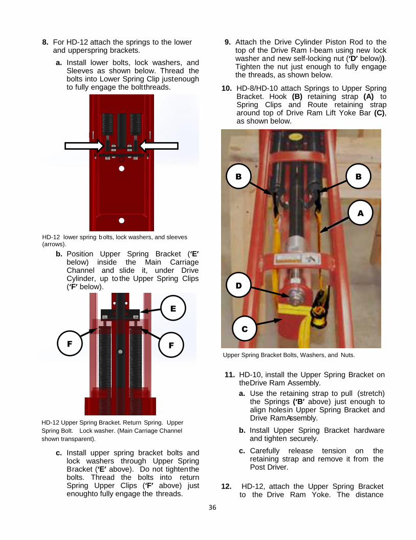
36
8. For HD-12 attach the springs to the lower and upper spring brackets.
a. Install lower bolts, lock washers, and Sleeves as shown below. Thread the bolts into Lower Spring Clip just enough to fully engage the bolt threads.
HD-12 lower spring bolts, lock washers, and sleeves (arrows).
b. Position Upper Spring Bracket (‘E’ below) inside the Main Carriage Channel and slide it, under Drive Cylinder, up to the Upper Spring Clips (‘F’ below).
HD-12 Upper Spring Bracket. Return Spring. Upper
Spring Bolt. Lock washer. (Main Carriage Channel
shown transparent).
c. Install upper spring bracket bolts and lock washers through Upper Spring Bracket (‘E’ above). Do not tighten the bolts. Thread the bolts into return Spring Upper Clips (‘F’ above) just enough to fully engage the threads.
9. Attach the Drive Cylinder Piston Rod to the top of the Drive Ram I-beam using new lock washer and new self-locking nut (‘D’ below)). Tighten the nut just enough to fully engage the threads, as shown below.
10. HD-8/HD-10 attach Springs to Upper Spring Bracket. Hook (B) retaining strap (A) to Spring Clips and Route retaining strap around top of Drive Ram Lift Yoke Bar (C), as shown below.
Upper Spring Bracket Bolts, Washers, and Nuts.
11. HD-10, install the Upper Spring Bracket on the Drive Ram Assembly.
a. Use the retaining strap to pull (stretch) the Springs (‘B’ above) just enough to align holes in Upper Spring Bracket and Drive Ram Assembly.
b. Install Upper Spring Bracket hardware and tighten securely.
c. Carefully release tension on the retaining strap and remove it from the Post Driver.
12. HD-12, attach the Upper Spring Bracket to the Drive Ram Yoke. The distance
A
B
B
C
A
D
A
E
F
F
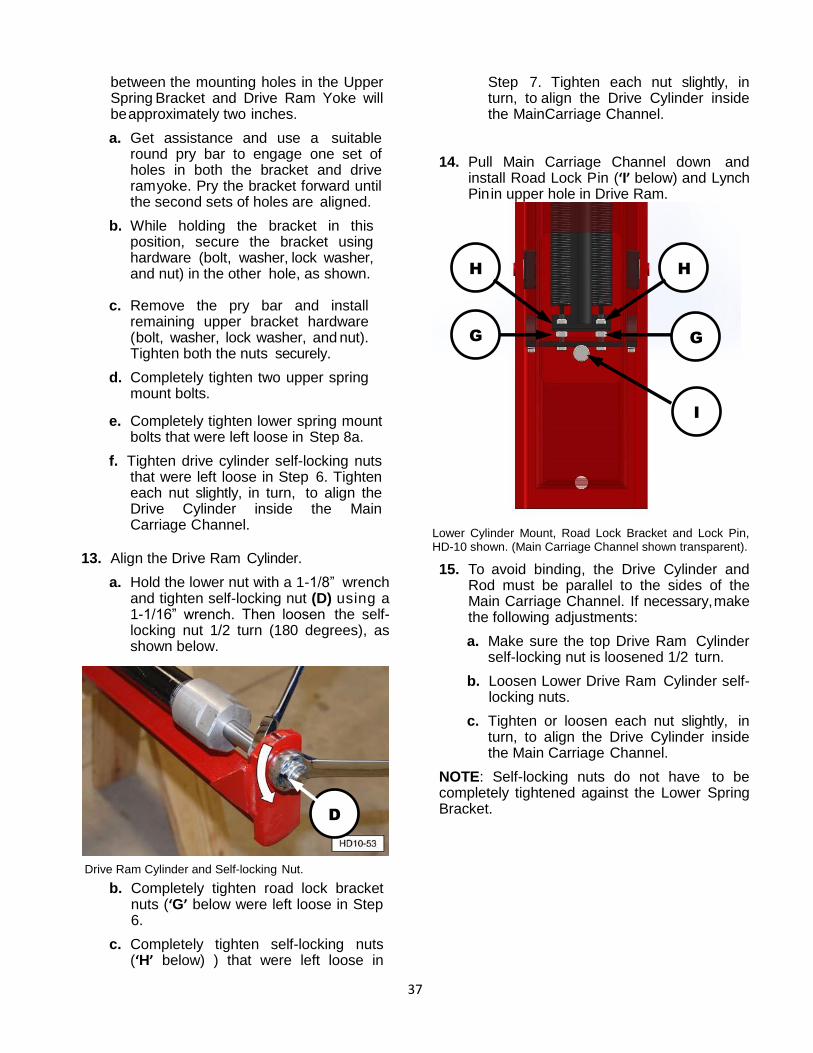
37
between the mounting holes in the Upper Spring Bracket and Drive Ram Yoke will be approximately two inches.
a. Get assistance and use a suitable round pry bar to engage one set of holes in both the bracket and drive ram yoke. Pry the bracket forward until the second sets of holes are aligned.
b. While holding the bracket in this position, secure the bracket using hardware (bolt, washer, lock washer, and nut) in the other hole, as shown.
c. Remove the pry bar and install remaining upper bracket hardware (bolt, washer, lock washer, and nut). Tighten both the nuts securely.
d. Completely tighten two upper spring mount bolts.
e. Completely tighten lower spring mount bolts that were left loose in Step 8a.
f. Tighten drive cylinder self-locking nuts that were left loose in Step 6. Tighten each nut slightly, in turn, to align the Drive Cylinder inside the Main Carriage Channel.
13. Align the Drive Ram Cylinder.
a. Hold the lower nut with a 1-1/8” wrench and tighten self-locking nut (D) using a 1-1/16” wrench. Then loosen the self-locking nut 1/2 turn (180 degrees), as shown below.
Drive Ram Cylinder and Self-locking Nut.
b. Completely tighten road lock bracket nuts (‘G’ below were left loose in Step 6.
c. Completely tighten self-locking nuts (‘H’ below) ) that were left loose in
Step 7. Tighten each nut slightly, in turn, to align the Drive Cylinder inside the Main Carriage Channel.
14. Pull Main Carriage Channel down and
install Road Lock Pin (‘I’ below) and Lynch Pin in upper hole in Drive Ram.
Lower Cylinder Mount, Road Lock Bracket and Lock Pin, HD-10 shown. (Main Carriage Channel shown transparent).
15. To avoid binding, the Drive Cylinder and Rod must be parallel to the sides of the Main Carriage Channel. If necessary, make the following adjustments:
a. Make sure the top Drive Ram Cylinder self-locking nut is loosened 1/2 turn.
b. Loosen Lower Drive Ram Cylinder self-locking nuts.
c. Tighten or loosen each nut slightly, in turn, to align the Drive Cylinder inside the Main Carriage Channel.
NOTE: Self-locking nuts do not have to be completely tightened against the Lower Spring Bracket.
D
A
I
A
G
A
H
A
H
A
G
A
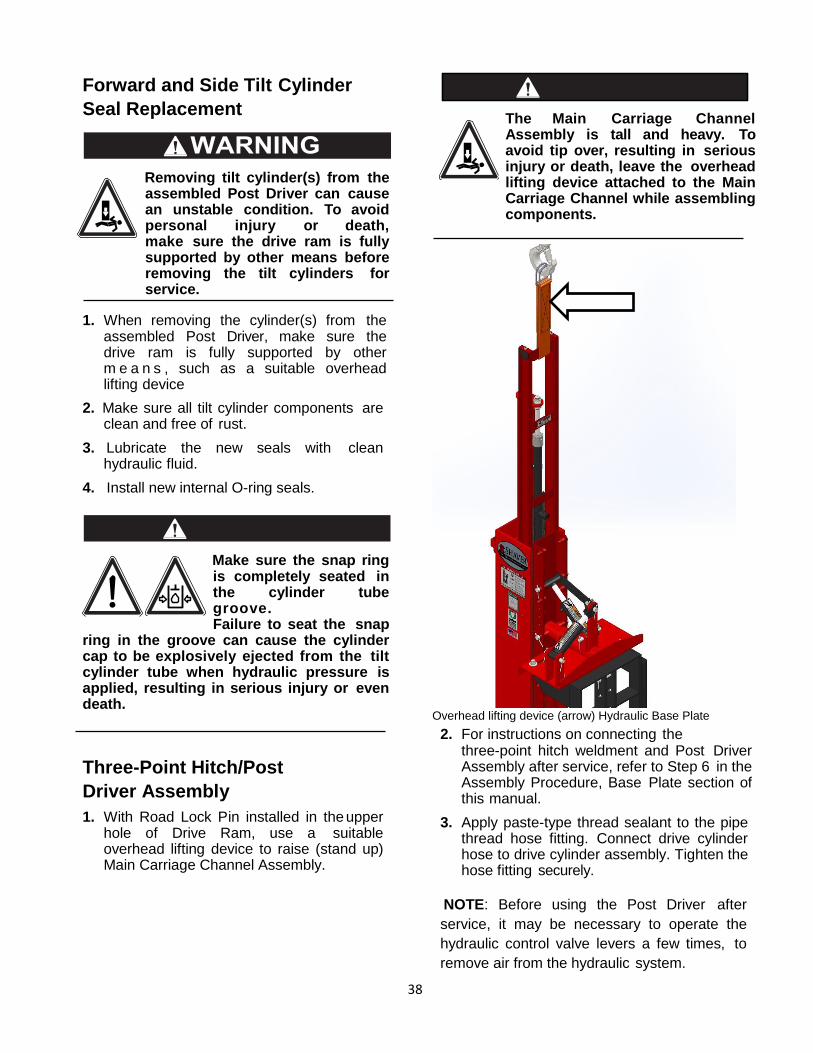
38
Forward and Side Tilt Cylinder
Seal Replacement
Removing tilt cylinder(s) from the assembled Post Driver can cause an unstable condition. To avoid personal injury or death, make sure the drive ram is fully supported by other means before removing the tilt cylinders for service.
1. When removing the cylinder(s) from the assembled Post Driver, make sure the drive ram is fully supported by other m e a n s , such as a suitable overhead lifting device
2. Make sure all tilt cylinder components are clean and free of rust.
3. Lubricate the new seals with clean hydraulic fluid.
4. Install new internal O-ring seals.
Make sure the snap ring is completely seated in the cylinder tube groove. Failure to seat the snap
ring in the groove can cause the cylinder cap to be explosively ejected from the tilt cylinder tube when hydraulic pressure is applied, resulting in serious injury or even death.
Three-Point Hitch/Post
Driver Assembly
1. With Road Lock Pin installed in the upper hole of Drive Ram, use a suitable overhead lifting device to raise (stand up) Main Carriage Channel Assembly.
The Main Carriage Channel Assembly is tall and heavy. To avoid tip over, resulting in serious injury or death, leave the overhead lifting device attached to the Main Carriage Channel while assembling components.
Overhead lifting device (arrow) Hydraulic Base Plate
2. For instructions on connecting the three-point hitch weldment and Post Driver Assembly after service, refer to Step 6 in the Assembly Procedure, Base Plate section of this manual.
3. Apply paste-type thread sealant to the pipe thread hose fitting. Connect drive cylinder hose to drive cylinder assembly. Tighten the hose fitting securely.
NOTE: Before using the Post Driver after
service, it may be necessary to operate the
hydraulic control valve levers a few times, to
remove air from the hydraulic system.
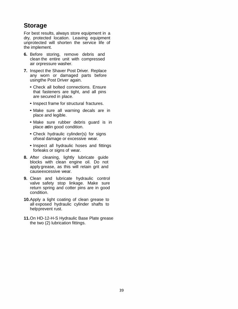
39
Storage For best results, always store equipment in a dry, protected location. Leaving equipment unprotected will shorten the service life of the implement.
6. Before storing, remove debris and clean the entire unit with compressed air or pressure washer.
7. Inspect the Shaver Post Driver. Replace any worn or damaged parts before using the Post Driver again.
• Check all bolted connections. Ensure that fasteners are tight, and all pins are secured in place.
• Inspect frame for structural fractures.
• Make sure all warning decals are in place and legible.
• Make sure rubber debris guard is in place and in good condition.
• Check hydraulic cylinder(s) for signs of seal damage or excessive wear.
• Inspect all hydraulic hoses and fittings for leaks or signs of wear.
8. After cleaning, lightly lubricate guide blocks with clean engine oil. Do not apply grease, as this will retain grit and cause excessive wear.
9. Clean and lubricate hydraulic control valve safety stop linkage. Make sure return spring and cotter pins are in good condition.
10. Apply a light coating of clean grease to all exposed hydraulic cylinder shafts to help prevent rust.
11. On HD-12-H-S Hydraulic Base Plate grease
the two (2) lubrication fittings.
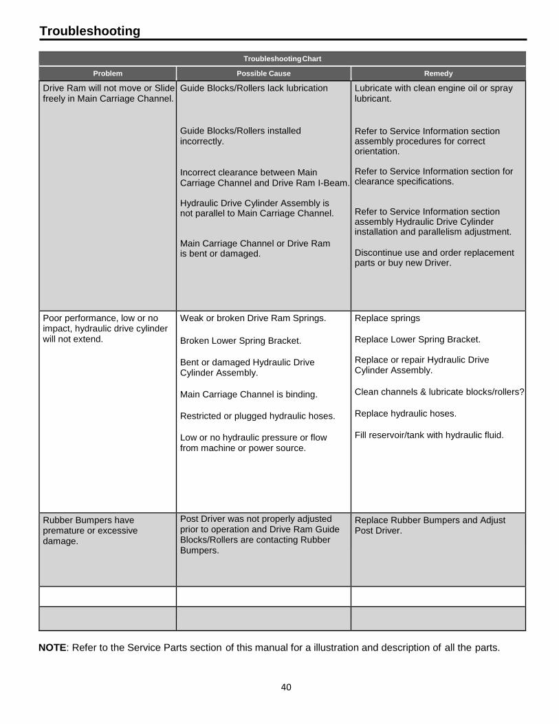
40
Troubleshooting
Troubleshooting Chart
Problem Possible Cause Remedy
Drive Ram will not move or Slide freely in Main Carriage Channel.
Guide Blocks/Rollers lack lubrication
Guide Blocks/Rollers installed incorrectly.
Incorrect clearance between Main Carriage Channel and Drive Ram I-Beam.
Hydraulic Drive Cylinder Assembly is not parallel to Main Carriage Channel.
Main Carriage Channel or Drive Ram is bent or damaged.
Lubricate with clean engine oil or spray lubricant.
Refer to Service Information section assembly procedures for correct orientation. Refer to Service Information section for clearance specifications. Refer to Service Information section assembly Hydraulic Drive Cylinder installation and parallelism adjustment.
Discontinue use and order replacement parts or buy new Driver.
Poor performance, low or no impact, hydraulic drive cylinder will not extend.
Weak or broken Drive Ram Springs.
Broken Lower Spring Bracket.
Bent or damaged Hydraulic Drive Cylinder Assembly.
Main Carriage Channel is binding.
Restricted or plugged hydraulic hoses.
Low or no hydraulic pressure or flow from machine or power source.
Replace springs
Replace Lower Spring Bracket.
Replace or repair Hydraulic Drive Cylinder Assembly.
Clean channels & lubricate blocks/rollers?
Replace hydraulic hoses.
Fill reservoir/tank with hydraulic fluid.
Rubber Bumpers have premature or excessive damage.
Post Driver was not properly adjusted prior to operation and Drive Ram Guide Blocks/Rollers are contacting Rubber Bumpers.
Replace Rubber Bumpers and Adjust Post Driver.
NOTE: Refer to the Service Parts section of this manual for a illustration and description of all the parts.

41
NOTES
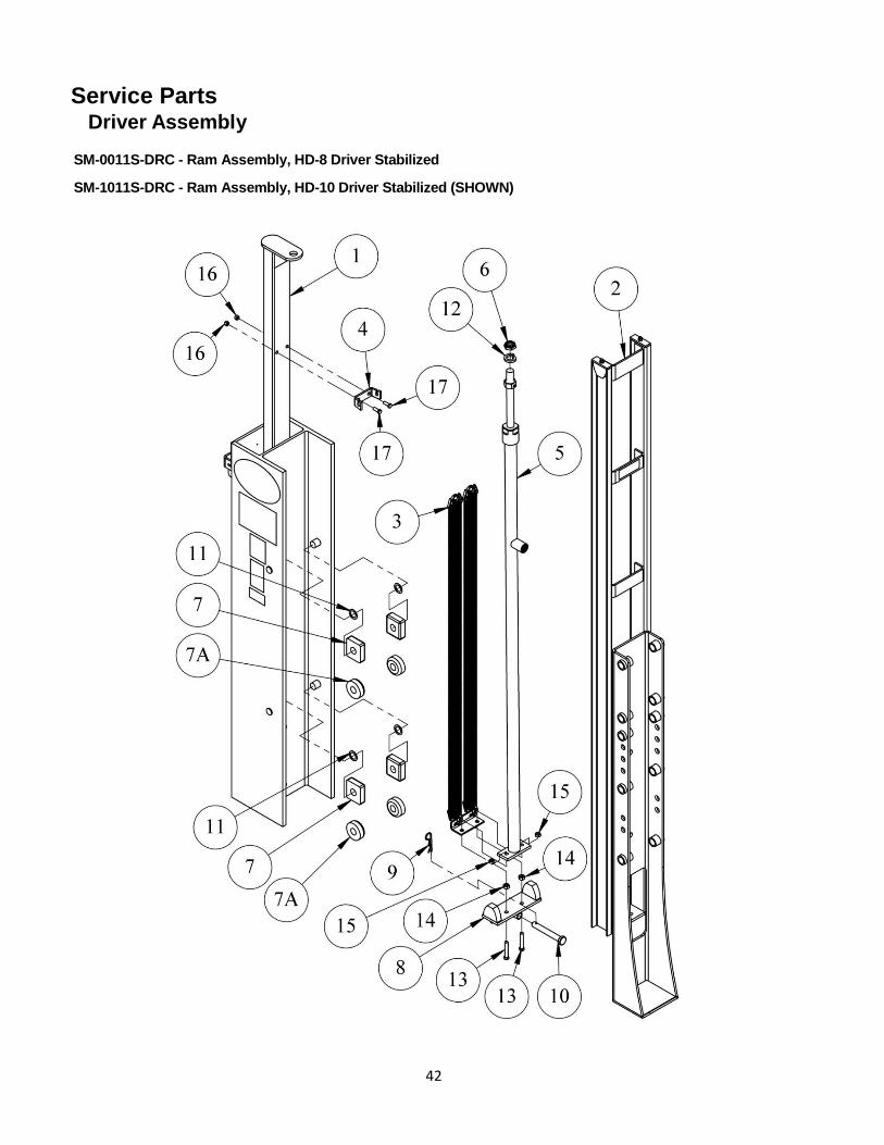
42
Service Parts Driver Assembly
SM-0011S-DRC - Ram Assembly, HD-8 Driver Stabilized
SM-1011S-DRC - Ram Assembly, HD-10 Driver Stabilized (SHOWN)

43
Driver Assembly
SM-0011S-DRC - Ram Assembly, HD-8 Driver Stabilized
SM-1011S-DRC - Ram Assembly, HD-10 Driver Stabilized (SHOWN)
Item Qty.
SM-0011S-DRC
HD-8
Qty.
SM-1011S-DRC
HD-10 (Shown)
Part No. Description
1 1 - SM-0011-DRO Ram Assembly, Driving, Only, HD-8
- 1 SM-1011-DRO Ram Assembly, Driving, Only, HD-10 (Shown)
2 1 - SM-00412S Carriage Assembly, HD-8 Stabilized
- 1 SM-10412S Carriage Assembly, HD-10 Stabilized (Shown)
3 1 - SM-0011-SA Spring Assembly, HD-8
- 1 SM-1011-SA Spring Assembly, HD-10 (Shown)
4 - 1 SM-1011-SBU Bracket, Upper, HD-10 Spring
5 1 - SM-0263-S Cylinder Assembly, Complete HD-8
- 1 SM-1026-S Cylinder Assembly, Complete HD-10/12 (Shown)
6 1 - SM-0267 Locknut, Piston, HD-8
- 1 SM-10267 Locknut, Piston, 1-8 Nylon (Shown)
7 4* 4*
SM-00512R Block, Nyrim
7A SM-00510 Roller, UHMW, Driver
- * * SM-00512 Nyrim Block – Pack of 4 (Not Shown)
SM-00510-4 UHMW Rollers – Pack of 4 (Not Shown)
8 1 - SM-0041-RLB Bracket Assembly, Road Lock HD-8
- 1 SM-1041-RLBPC Plate Assembly, Road Lock HD-10 (Shown)
9 1 1 SM-1041-RLC Clip, Road Lock
10 1 1 SM-1041-RLP Pin, Road Lock
11
AR AR SM-0933 Shim, 18 Ga.(.0478”) Driver (Shown)
AR AR SM-0934 Shim, 14 Ga.(.0747”) Driver
AR AR SM-0935 Shim, 10 Ga.(.1345”) Driver
12 1 - 300166 Washer, Lock 3/4"
- 1 300112 Washer, Lock 1"(Shown)
13 2 - 300194 Bolt, Tap 3/8-16 x 2 Hex Head Gr5 Zn
- 2 300113 Bolt, Tap 7/16-14 x 2-1/2 Hex Head Gr5 Zn (Shown)
14 2 - 300180 Hex Nut, Heavy Pattern 3/8-16 Zn
- 2 300115 Hex Nut, Heavy Pattern 7/16-14 Zn (Shown)
15 2 - 300181 Nut, Cone 3/8-16 Lock Zn
- 2 300356 Nut, Cone 7/16-14 Lock Zn (Shown)
16 - 2 300181 Nut, Cone 3/8-16 Lock Zn
17 - 2 300189 Bolt, Tap 3/8-16 x 1 Hex Head Gr5 Zn
*When replacing Blocks/Rollers use all of the same type.
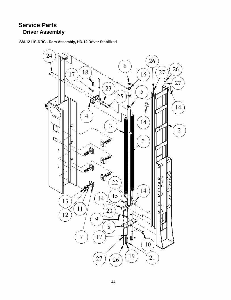
44
Service Parts Driver Assembly
SM-1211S-DRC - Ram Assembly, HD-12 Driver Stabilized

45
Driver Assembly
SM-1211S-DRC - Ram Assembly, HD-12 Driver Stabilize
Item Qty.
Part No. Description
1 1 SM-1211-DRO Ram Assembly, Driving, Only, HD-12
2 1 SM-12412S Carriage Assembly, HD-12 Stabilized
3 1 SM-1211-DRSA Spring Assembly, HD-12
4 1 SM-1211-SBU Bracket, Upper, HD-12 Spring
5 1 SM-1026-S Cylinder Assembly, Complete HD-10/12
6 1 SM-10267 Locknut, Piston, 1-8 Nylon
7 6 SM-00512R Block, Nyrim
- - SM-00512 Nyrim Block – Pack of 4 (Not Shown)
8 1 SM-1241-RLBC Bracket Weldment, Road Lock HD-12
9 1 SM-1041-RLC Clip, Road Lock
10 1 SM-1041-RLP Pin, Road Lock
11 AR SM-0933 Shim, 18 Ga.(.0478”) Driver
12 AR SM-0934 Shim, 14 Ga.(.0747”) Driver
13 AR SM-0935 Shim, 10 Ga.(.1345”) Driver
14 4 SM-0041-BR Bumper, Rubber
15 2 SD-101-B2 Bushing, 1-7/8 OD x 5/8 ID x 2 L
16 1 300112 Washer, Lock 1" Zn
17 4 300101 Washer, Lock 1/2" Zn
18 2 300132 Screw, Cap 1/2-13 x 2 Hex Head Gr5 Zn Full Thread
19 2 300137 Bolt, Tap 1/2-13 x 4-1/2 Hex Head Gr5 Zn Full Thread
20 2 300115 Nut, Hex 7/16-14 Heavy Pattern Zn
21 2 300113 Bolt, Tap 7/16-14 x 2-1/2 Hex Head Gr5 Zn
22 2 300356 Nut, Cone 7/16-14 Lock Zn
23 2 300178 Washer , Flat 3/8” Zn
24 2 300181 Nut, Cone 3/8-16 Lock Zn
25 2 300184 Screw, Cap 3/8-16 x 1-1/2 Hex Head Gr5 Zn
26 4 300203 Nut, Hex 5/16-18 Zn
27 4 300204 Washer, Lock 5/16” Zn
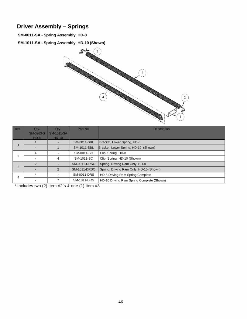
46
Driver Assembly – Springs
SM-0011-SA - Spring Assembly, HD-8
SM-1011-SA - Spring Assembly, HD-10 (Shown)
Item Qty.
SM-0263-S
HD-8
Qty.
SM-1011-SA
HD-10
Part No. Description
1 1 - SM-0011-SBL Bracket, Lower Spring, HD-8
- 1 SM-1011-SBL Bracket, Lower Spring, HD-10 (Shown)
2 4 - SM-0011-SC Clip, Spring, HD-8
- 4 SM-1011-SC Clip, Spring, HD-10 (Shown)
3 2 - SM-0011-DRSO Spring, Driving Ram Only, HD-8
- 2 SM-1011-DRSO Spring, Driving Ram Only, HD-10 (Shown)
4 * - SM-0011-DRS HD-8 Driving Ram Spring Complete
- * SM-1011-DRS HD-10 Driving Ram Spring Complete (Shown)
* Includes two (2) Item #2’s & one (1) Item #3
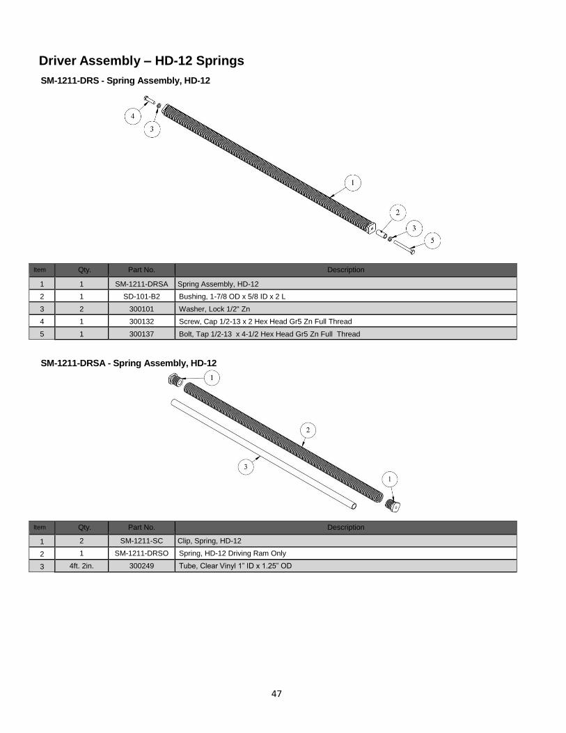
47
Driver Assembly – HD-12 Springs
SM-1211-DRS - Spring Assembly, HD-12
Item Qty.
Part No. Description
1 1 SM-1211-DRSA Spring Assembly, HD-12
2 1 SD-101-B2 Bushing, 1-7/8 OD x 5/8 ID x 2 L
3 2 300101 Washer, Lock 1/2" Zn
4 1 300132 Screw, Cap 1/2-13 x 2 Hex Head Gr5 Zn Full Thread
5 1 300137 Bolt, Tap 1/2-13 x 4-1/2 Hex Head Gr5 Zn Full Thread
SM-1211-DRSA - Spring Assembly, HD-12
Item Qty.
Part No. Description
1 2 SM-1211-SC Clip, Spring, HD-12
2 1 SM-1211-DRSO Spring, HD-12 Driving Ram Only
3 4ft. 2in. 300249 Tube, Clear Vinyl 1” ID x 1.25” OD
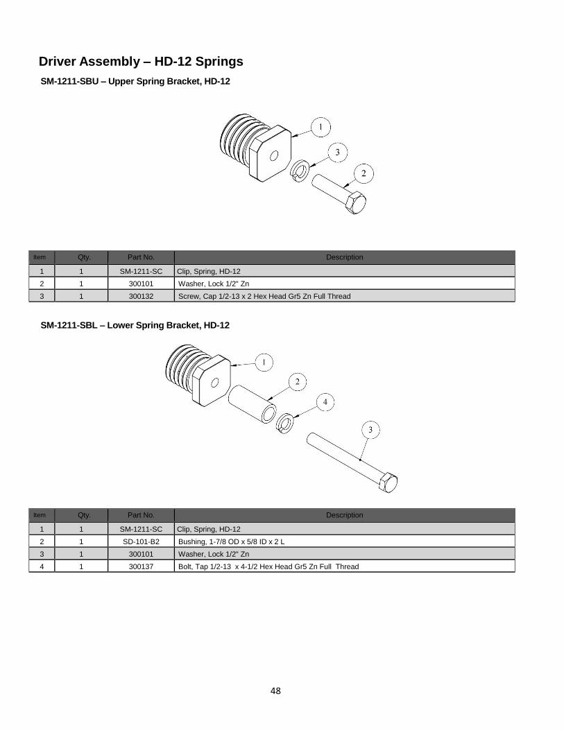
48
Driver Assembly – HD-12 Springs
SM-1211-SBU – Upper Spring Bracket, HD-12
Item Qty.
Part No. Description
1 1 SM-1211-SC Clip, Spring, HD-12
2 1 300101 Washer, Lock 1/2" Zn
3 1 300132 Screw, Cap 1/2-13 x 2 Hex Head Gr5 Zn Full Thread
SM-1211-SBL – Lower Spring Bracket, HD-12
Item Qty.
Part No. Description
1 1 SM-1211-SC Clip, Spring, HD-12
2 1 SD-101-B2 Bushing, 1-7/8 OD x 5/8 ID x 2 L
3 1 300101 Washer, Lock 1/2" Zn
4 1 300137 Bolt, Tap 1/2-13 x 4-1/2 Hex Head Gr5 Zn Full Thread
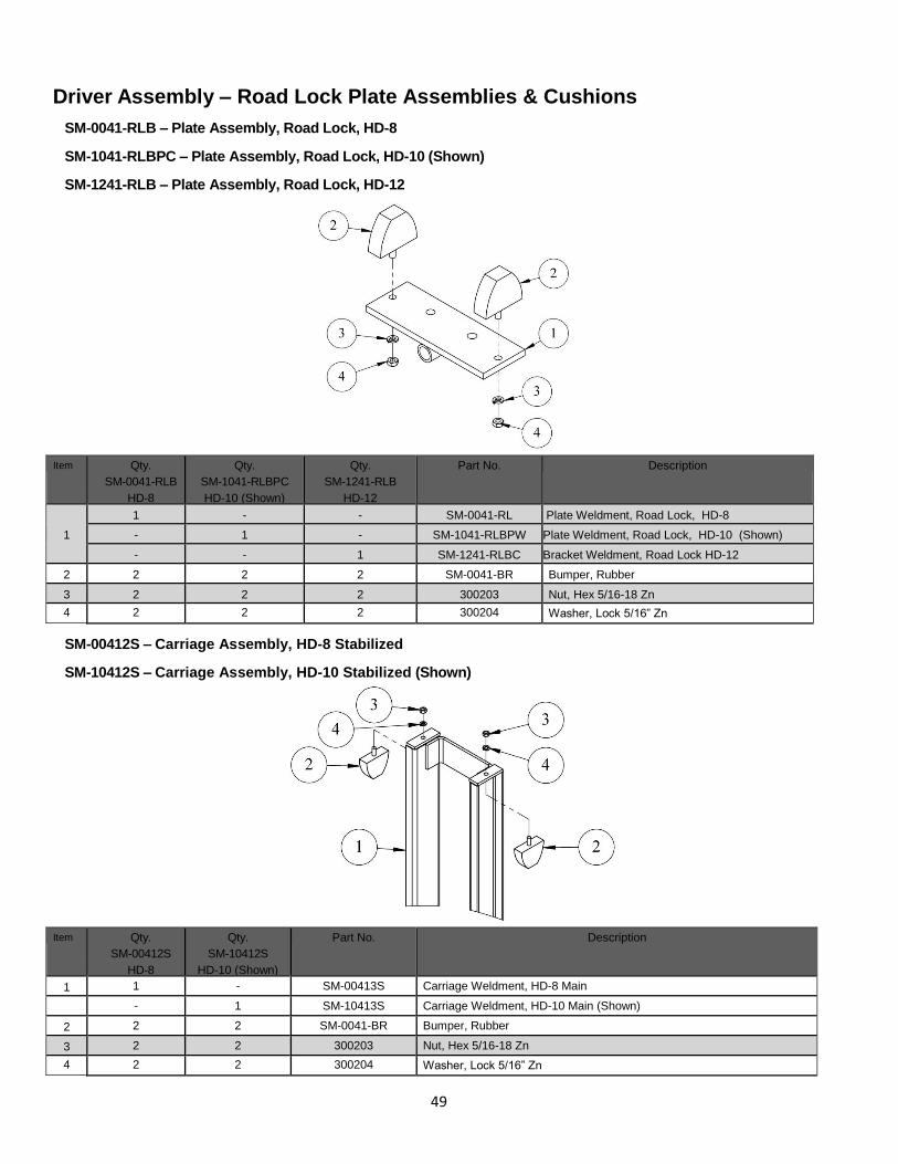
49
Driver Assembly – Road Lock Plate Assemblies & Cushions
SM-0041-RLB – Plate Assembly, Road Lock, HD-8
SM-1041-RLBPC – Plate Assembly, Road Lock, HD-10 (Shown)
SM-1241-RLB – Plate Assembly, Road Lock, HD-12
Item Qty.
SM-0041-RLB
HD-8
Qty.
SM-1041-RLBPC
HD-10 (Shown)
Qty.
SM-1241-RLB
HD-12
Part No. Description
1
1 - - SM-0041-RL Plate Weldment, Road Lock, HD-8
- 1 - SM-1041-RLBPW Plate Weldment, Road Lock, HD-10 (Shown)
- - 1 SM-1241-RLBC Bracket Weldment, Road Lock HD-12
2 2 2 2 SM-0041-BR Bumper, Rubber
3 2 2 2 300203 Nut, Hex 5/16-18 Zn
4 2 2 2 300204 Washer, Lock 5/16” Zn
SM-00412S – Carriage Assembly, HD-8 Stabilized
SM-10412S – Carriage Assembly, HD-10 Stabilized (Shown)
Item Qty.
SM-00412S
HD-8
Qty.
SM-10412S
HD-10 (Shown)
Part No. Description
1 1 - SM-00413S Carriage Weldment, HD-8 Main
- 1 SM-10413S Carriage Weldment, HD-10 Main (Shown)
2 2 2 SM-0041-BR Bumper, Rubber
3 2 2 300203 Nut, Hex 5/16-18 Zn
4 2 2 300204 Washer, Lock 5/16” Zn
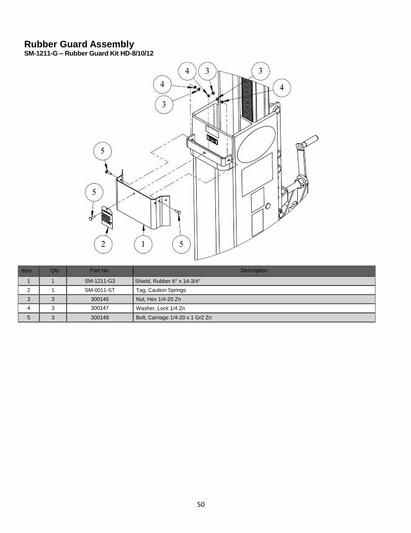
50
Rubber Guard Assembly SM-1211-G – Rubber Guard Kit HD-8/10/12
Item Qty.
Part No. Description
1 1 SM-1211-G3 Shield, Rubber 6” x 14-3/4”
2 1 SM-0011-ST Tag, Caution Springs
3 3 300145 Nut, Hex 1/4-20 Zn
4 3 300147 Washer, Lock 1/4 Zn
5 3 300149 Bolt, Carriage 1/4-20 x 1 Gr2 Zn
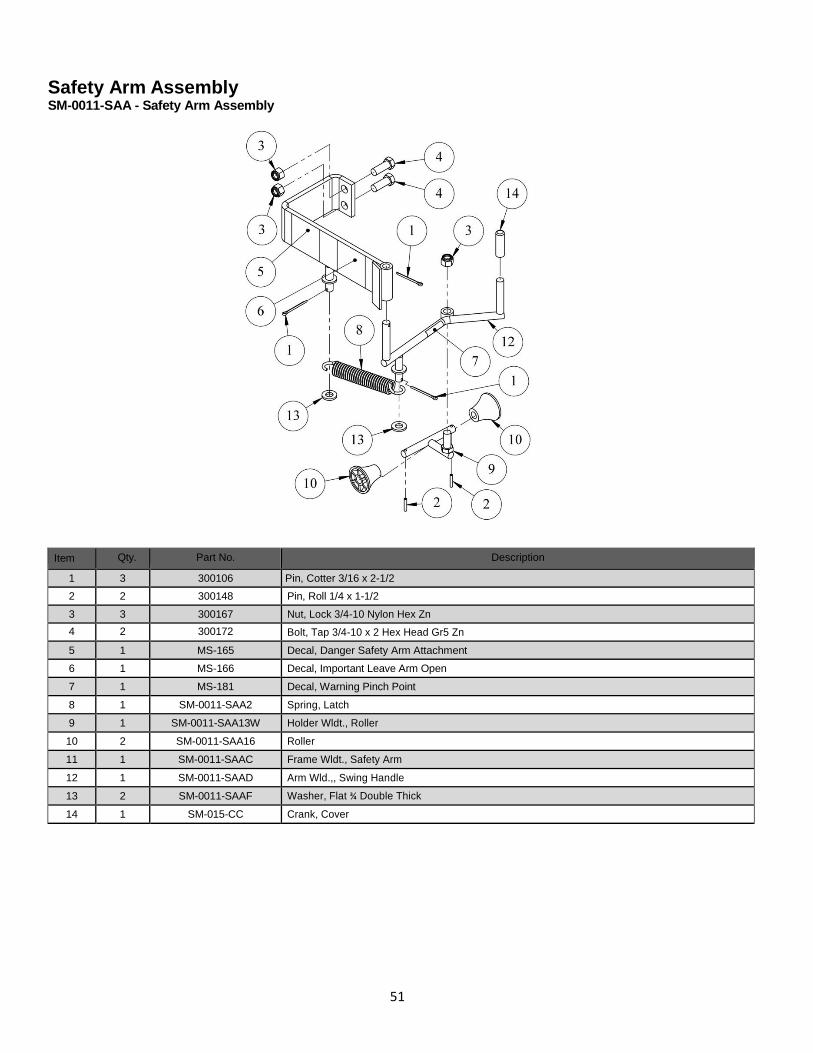
51
Safety Arm Assembly SM-0011-SAA - Safety Arm Assembly
Item Qty.
Part No. Description
1 3 300106 Pin, Cotter 3/16 x 2-1/2
2 2 300148 Pin, Roll 1/4 x 1-1/2
3 3 300167 Nut, Lock 3/4-10 Nylon Hex Zn
4 2 300172 Bolt, Tap 3/4-10 x 2 Hex Head Gr5 Zn
5 1 MS-165 Decal, Danger Safety Arm Attachment
6 1 MS-166 Decal, Important Leave Arm Open
7 1 MS-181 Decal, Warning Pinch Point
8 1 SM-0011-SAA2 Spring, Latch
9 1 SM-0011-SAA13W Holder Wldt., Roller
10 2 SM-0011-SAA16 Roller
11 1 SM-0011-SAAC Frame Wldt., Safety Arm
12 1 SM-0011-SAAD Arm Wld.,, Swing Handle
13 2 SM-0011-SAAF Washer, Flat ¾ Double Thick
14 1 SM-015-CC Crank, Cover
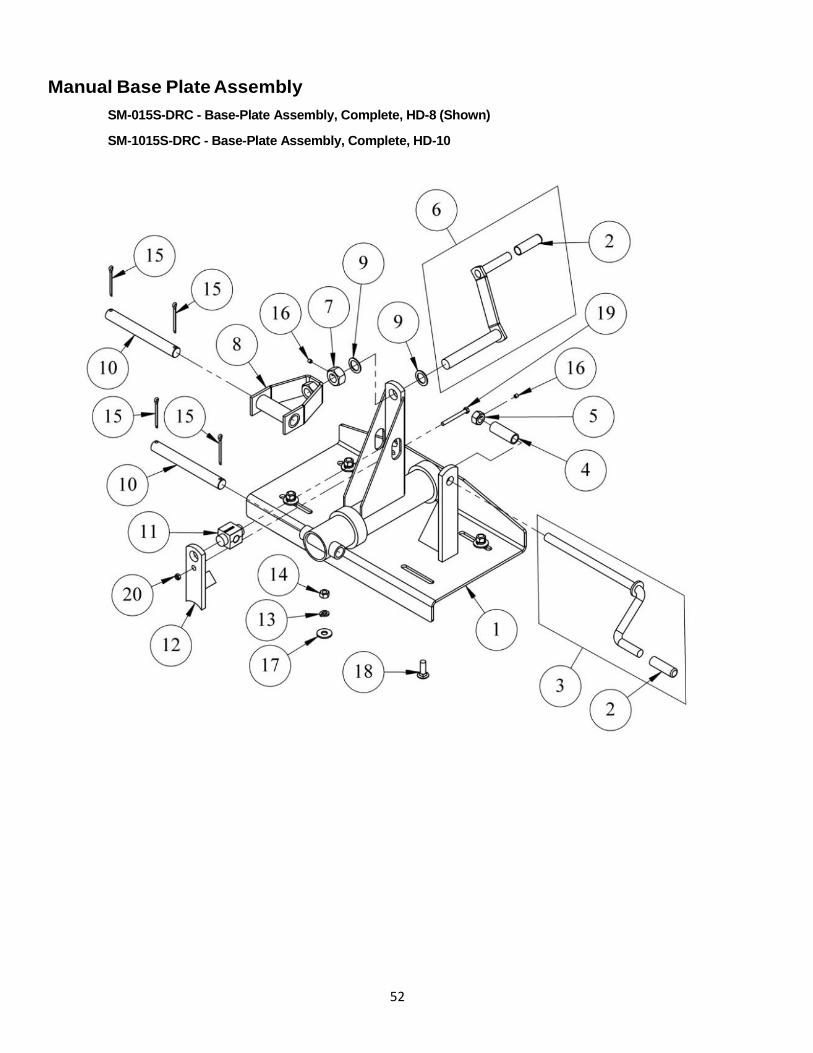
52
Manual Base Plate Assembly
SM-015S-DRC - Base-Plate Assembly, Complete, HD-8 (Shown)
SM-1015S-DRC - Base-Plate Assembly, Complete, HD-10
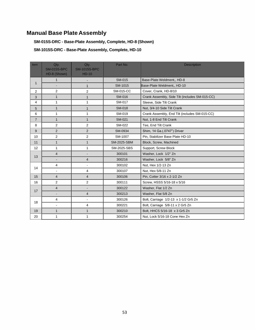
53
Manual Base Plate Assembly
SM-015S-DRC - Base-Plate Assembly, Complete, HD-8 (Shown)
SM-1015S-DRC - Base-Plate Assembly, Complete, HD-10
Item Qty.
SM-015S-BPC
HD-8 (Shown)
Qty.
SM-1015S-BPC
HD-10
Part No. Description
1 1 - SM-015 Base-Plate Weldment,, HD-8
- 1 SM-1015 Base-Plate Weldment,, HD-10
2 2 2 SM-015-CC Cover, Crank, HD-8/10
3 1 1 SM-016 Crank Assembly, Side Tilt (includes SM-015-CC)
4 1 1 SM-017 Sleeve, Side Tilt Crank
5 1 1 SM-018 Nut, 3/4-10 Side Tilt Crank
6 1 1 SM-019 Crank Assembly, End Tilt (includes SM-015-CC)
7 1 1 SM-021 Nut, 1-8 End Tilt Crank
8 2 2 SM-022 Tee, End Tilt Crank
9 2 2 SM-0934 Shim, 14 Ga.(.0747”) Driver
10 2 2 SM-1007 Pin, Stabilizer Base Plate HD-10
11 1 1 SM-2025-SBM Block, Screw, Machined
12 1 1 SM-2025-SBS Support, Screw Block
13 4 - 300101 Washer, Lock 1/2" Zn
- 4 300216 Washer, Lock 5/8" Zn
14 4 - 300102 Nut, Hex 1/2-13 Zn
- 4 300107 Nut, Hex 5/8-11 Zn
15 4 4 300106 Pin, Cotter 3/16 x 2-1/2 Zn
16 2 2 300111 Screw, HSSS 5/16-18 x 5/16
17 4 - 300122 Washer, Flat 1/2 Zn
- 4 300213 Washer, Flat 5/8 Zn
18 4 - 300126 Bolt, Carriage 1/2-13 x 1-1/2 Gr5 Zn
- 4 300221 Bolt, Carriage 5/8-11 x 2 Gr5 Zn
19 1 1 300210 Bolt, HHCS 5/16-18 x 3 Gr5 Zn
20 1 1 300254 Nut, Lock 5/16-18 Cone Hex Zn
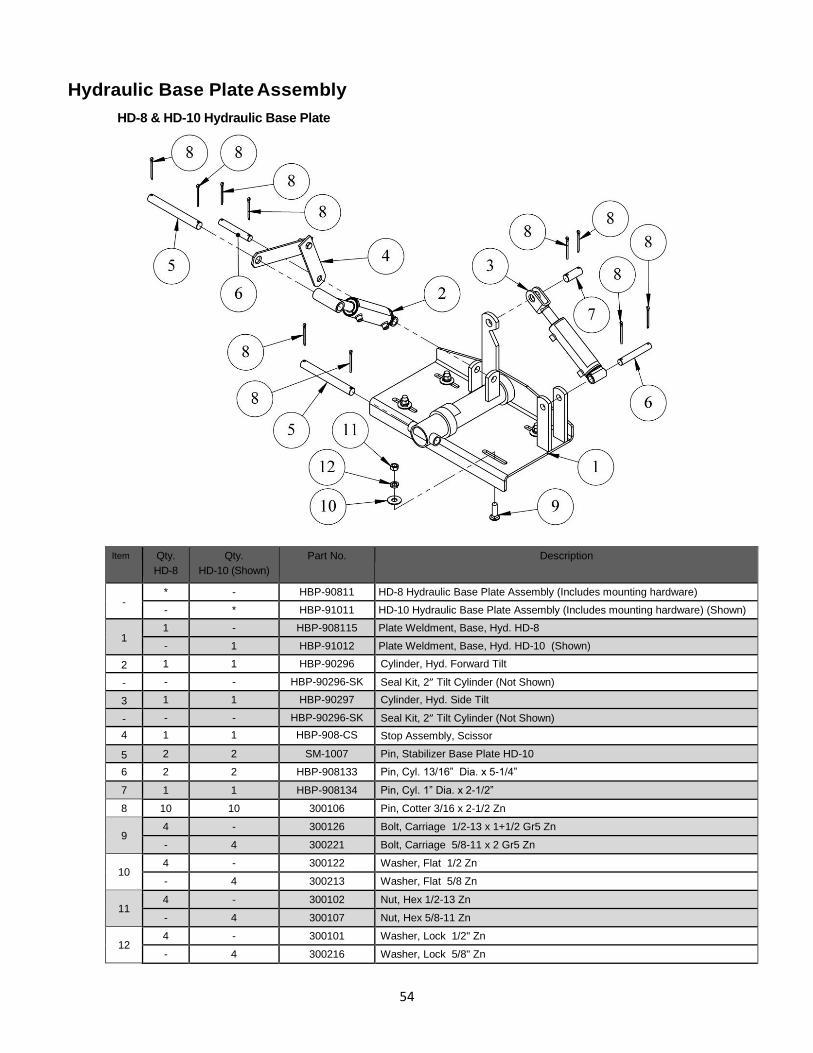
54
Hydraulic Base Plate Assembly
HD-8 & HD-10 Hydraulic Base Plate
Item Qty.
HD-8
Qty.
HD-10 (Shown)
Part No.
Description
- * - HBP-90811 HD-8 Hydraulic Base Plate Assembly (Includes mounting hardware)
- * HBP-91011 HD-10 Hydraulic Base Plate Assembly (Includes mounting hardware) (Shown)
1 1 - HBP-908115 Plate Weldment, Base, Hyd. HD-8
- 1 HBP-91012 Plate Weldment, Base, Hyd. HD-10 (Shown)
2 1 1 HBP-90296 Cylinder, Hyd. Forward Tilt
- - - HBP-90296-SK Seal Kit, 2” Tilt Cylinder (Not Shown)
3 1 1 HBP-90297 Cylinder, Hyd. Side Tilt
- - - HBP-90296-SK Seal Kit, 2” Tilt Cylinder (Not Shown)
4 1 1 HBP-908-CS Stop Assembly, Scissor
5 2 2 SM-1007 Pin, Stabilizer Base Plate HD-10
6 2 2 HBP-908133 Pin, Cyl. 13/16” Dia. x 5-1/4”
7 1 1 HBP-908134 Pin, Cyl. 1” Dia. x 2-1/2”
8 10 10 300106 Pin, Cotter 3/16 x 2-1/2 Zn
9 4 - 300126 Bolt, Carriage 1/2-13 x 1+1/2 Gr5 Zn
- 4 300221 Bolt, Carriage 5/8-11 x 2 Gr5 Zn
10 4 - 300122 Washer, Flat 1/2 Zn
- 4 300213 Washer, Flat 5/8 Zn
11 4 - 300102 Nut, Hex 1/2-13 Zn
- 4 300107 Nut, Hex 5/8-11 Zn
12 4 - 300101 Washer, Lock 1/2" Zn
- 4 300216 Washer, Lock 5/8" Zn
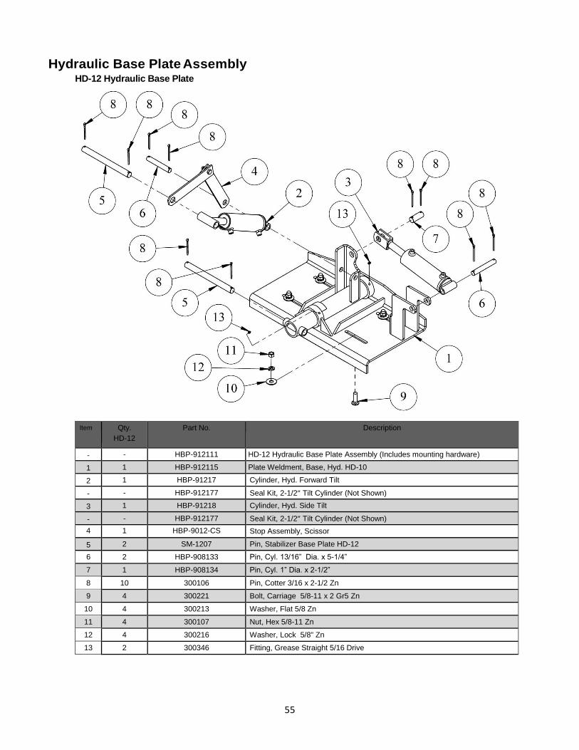
55
Hydraulic Base Plate Assembly HD-12 Hydraulic Base Plate
Item Qty.
HD-12
Part No.
Description
- - HBP-912111 HD-12 Hydraulic Base Plate Assembly (Includes mounting hardware)
1 1 HBP-912115 Plate Weldment, Base, Hyd. HD-10
2 1 HBP-91217 Cylinder, Hyd. Forward Tilt
- - HBP-912177 Seal Kit, 2-1/2” Tilt Cylinder (Not Shown)
3 1 HBP-91218 Cylinder, Hyd. Side Tilt
- - HBP-912177 Seal Kit, 2-1/2” Tilt Cylinder (Not Shown)
4 1 HBP-9012-CS Stop Assembly, Scissor
5 2 SM-1207 Pin, Stabilizer Base Plate HD-12
6 2 HBP-908133 Pin, Cyl. 13/16” Dia. x 5-1/4”
7 1 HBP-908134 Pin, Cyl. 1” Dia. x 2-1/2”
8 10 300106 Pin, Cotter 3/16 x 2-1/2 Zn
9 4 300221 Bolt, Carriage 5/8-11 x 2 Gr5 Zn
10 4 300213 Washer, Flat 5/8 Zn
11 4 300107 Nut, Hex 5/8-11 Zn
12 4 300216 Washer, Lock 5/8" Zn
13 2 300346 Fitting, Grease Straight 5/16 Drive
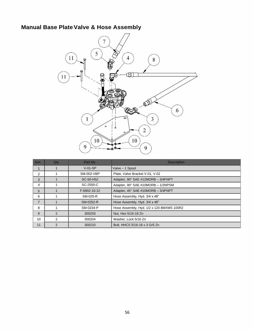
56
Manual Base Plate Valve & Hose Assembly
Item Qty.
Part No. Description
1 1 V-01-SP Valve – 1 Spool
2 1 SM-002-VBP Plate, Valve Bracket V-01, V-02
3 1 SC-50-H52 Adapter, 90° SAE #12MORB – 3/4FNPT
4 1 SC-2550-C Adapter, 90° SAE #10MORB – 1/2NPSM
5 1 F-6902-10-12 Adapter, 45° SAE #10MORB – 3/4FNPT
6 1 SM-025-R Hose Assembly, Hyd. 3/4 x 48”
7 1 SM-0252-R Hose Assembly, Hyd. 3/4 x 48”
8 1 SM-0234-P Hose Assembly, Hyd. 1/2 x 120 8MXMS 100R2
9 2 300203 Nut, Hex 5/16-18 Zn
10 2 300204 Washer, Lock 5/16 Zn
11 2 300210 Bolt, HHCS 5/16-18 x 3 Gr5 Zn
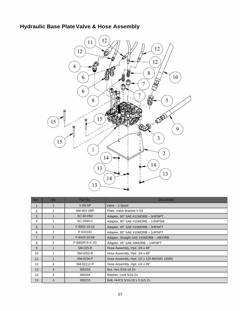
57
Hydraulic Base Plate Valve & Hose Assembly
Item Qty.
Part No. Description
1 1 V-03-SP Valve – 3 Spool
2 1 SM-003-VBP Plate, Valve Bracket V-03
3 1 SC-50-H52 Adapter, 90° SAE #12MORB – 3/4FNPT
4 1 SC-2550-C Adapter, 90° SAE #10MORB – 1/2NPSM
5 1 F-6902-10-12 Adapter, 45° SAE #10MORB – 3/4FNPT
6 2 P-910181 Adapter, 90° SAE #10MORB – 1/4FNPT
7 2 F-6410-10-06 Adapter, Straight SAE #10MORB – #6FORB
8 2 F-6902R-6-4-.03 Adapter, 45° SAE #6MORB – 1/4FNPT
9 1 SM-025-R Hose Assembly, Hyd. 3/4 x 48”
10 1 SM-0252-R Hose Assembly, Hyd. 3/4 x 48”
11 1 SM-0234-P Hose Assembly, Hyd. 1/2 x 120 8MXMS 100R2
12 4 SM-02111-P Hose Assembly, Hyd. 1/4 x 26”
13 3 300203 Nut, Hex 5/16-18 Zn
14 3 300204 Washer, Lock 5/16 Zn
15 3 300210 Bolt, HHCS 5/16-18 x 3 Gr5 Zn
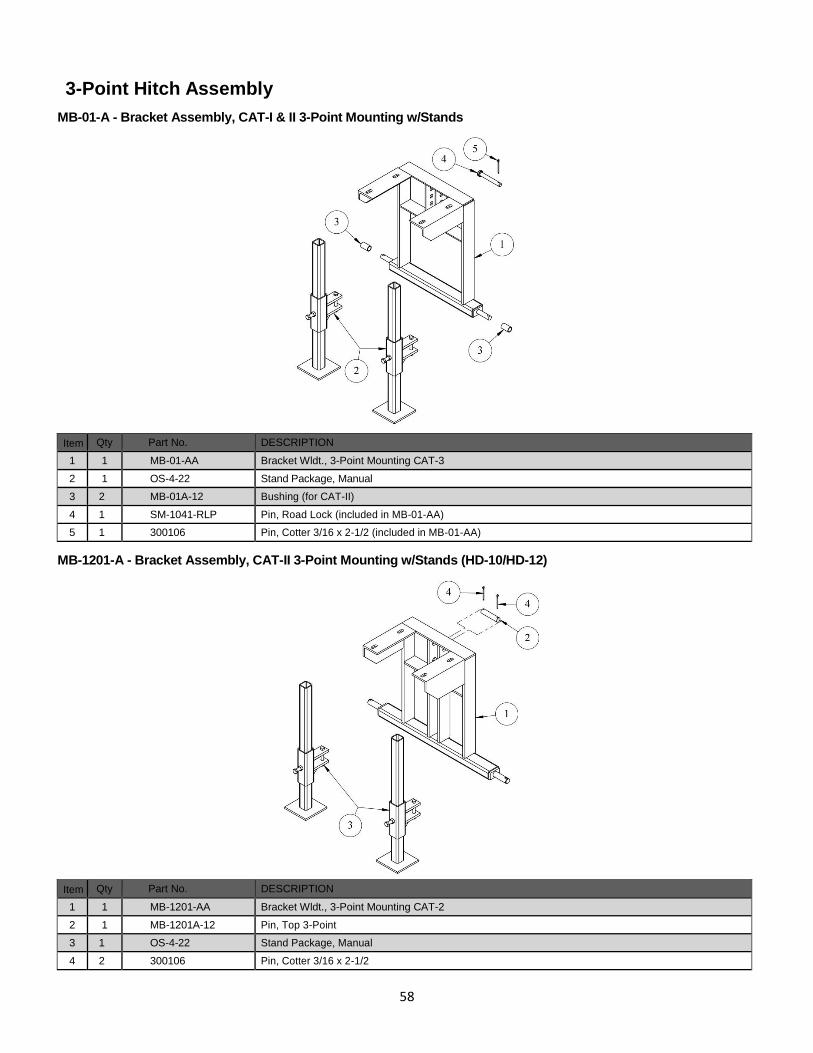
58
3-Point Hitch Assembly
MB-01-A - Bracket Assembly, CAT-I & II 3-Point Mounting w/Stands
Item Qty Part No. DESCRIPTION
1 1 MB-01-AA Bracket Wldt., 3-Point Mounting CAT-3
2 1 OS-4-22 Stand Package, Manual
3 2 MB-01A-12 Bushing (for CAT-II)
4 1 SM-1041-RLP Pin, Road Lock (included in MB-01-AA)
5 1 300106 Pin, Cotter 3/16 x 2-1/2 (included in MB-01-AA)
MB-1201-A - Bracket Assembly, CAT-II 3-Point Mounting w/Stands (HD-10/HD-12)
Item Qty Part No. DESCRIPTION
1 1 MB-1201-AA Bracket Wldt., 3-Point Mounting CAT-2
2 1 MB-1201A-12 Pin, Top 3-Point
3 1 OS-4-22 Stand Package, Manual
4 2 300106 Pin, Cotter 3/16 x 2-1/2
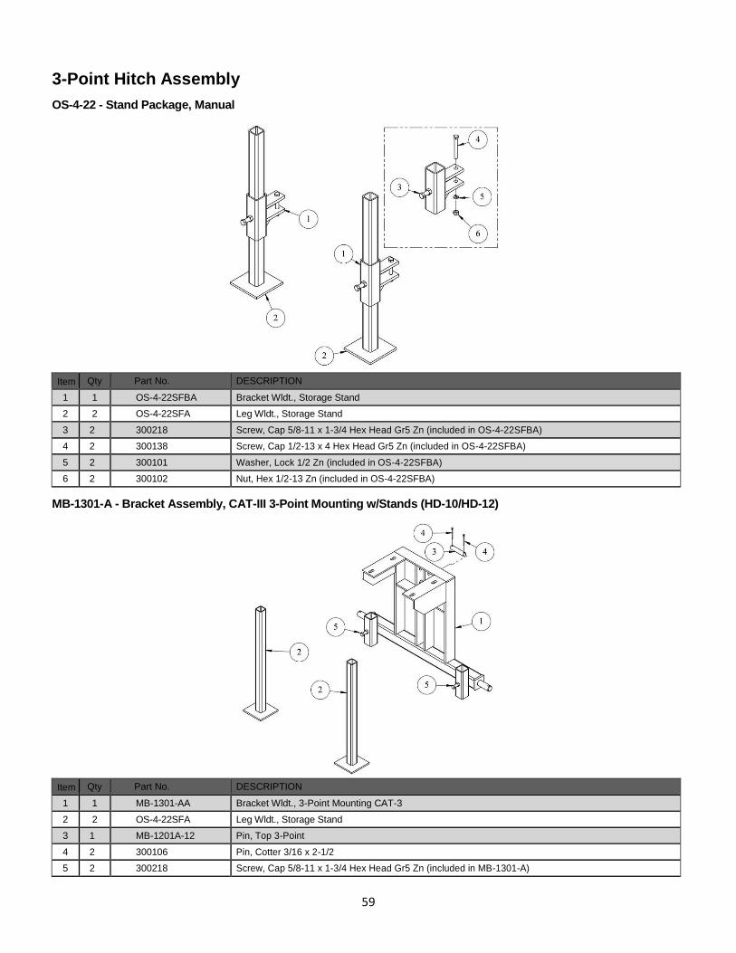
59
3-Point Hitch Assembly
OS-4-22 - Stand Package, Manual
Item Qty Part No. DESCRIPTION
1 1 OS-4-22SFBA Bracket Wldt., Storage Stand
2 2 OS-4-22SFA Leg Wldt., Storage Stand
3 2 300218 Screw, Cap 5/8-11 x 1-3/4 Hex Head Gr5 Zn (included in OS-4-22SFBA)
4 2 300138 Screw, Cap 1/2-13 x 4 Hex Head Gr5 Zn (included in OS-4-22SFBA)
5 2 300101 Washer, Lock 1/2 Zn (included in OS-4-22SFBA)
6 2 300102 Nut, Hex 1/2-13 Zn (included in OS-4-22SFBA)
MB-1301-A - Bracket Assembly, CAT-III 3-Point Mounting w/Stands (HD-10/HD-12)
Item Qty Part No. DESCRIPTION
1 1 MB-1301-AA Bracket Wldt., 3-Point Mounting CAT-3
2 2 OS-4-22SFA Leg Wldt., Storage Stand
3 1 MB-1201A-12 Pin, Top 3-Point
4 2 300106 Pin, Cotter 3/16 x 2-1/2
5 2 300218 Screw, Cap 5/8-11 x 1-3/4 Hex Head Gr5 Zn (included in MB-1301-A)
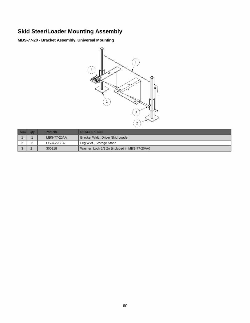
60
Skid Steer/Loader Mounting Assembly
MBS-77-20 - Bracket Assembly, Universal Mounting
Item Qty Part No. DESCRIPTION
1 1 MBS-77-20AA Bracket Wldt., Driver Skid Loader
2 2 OS-4-22SFA Leg Wldt., Storage Stand
3 2 300218 Washer, Lock 1/2 Zn (included in MBS-77-20AA)
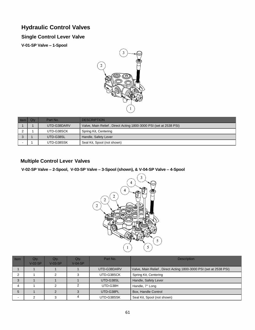
61
Hydraulic Control Valves
Single Control Lever Valve
V-01-SP Valve – 1-Spool
Item Qty Part No. DESCRIPTION
1 1 UTD-G38DARV Valve, Main Relief , Direct Acting 1800-3000 PSI (set at 2538 PSI)
2 1 UTD-G38SCK Spring Kit, Centering
3 1 UTD-G38SL Handle, Safety Lever
- 1 UTD-G38SSK Seal Kit, Spool (not shown)
Multiple Control Lever Valves
V-02-SP Valve – 2-Spool, V-03-SP Valve – 3-Spool (shown), & V-04-SP Valve – 4-Spool
Item Qty.
V-02-SP
Qty.
V-03-SP
Qty.
V-04-SP
Part No. Description
1 1 1 1 UTD-G38DARV Valve, Main Relief , Direct Acting 1800-3000 PSI (set at 2538 PSI)
2 1 2 3 UTD-G38SCK Spring Kit, Centering
3 1 1 1 UTD-G38SL Handle, Safety Lever
4 1 2 2 UTD-G38H Handle, 7” Long
5 1 2 3 UTD-G38PL Box, Handle Control
- 2 3 4 UTD-G38SSK Seal Kit, Spool (not shown)
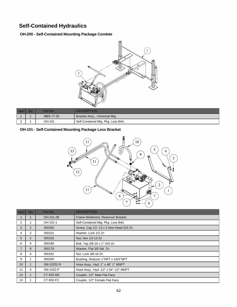
62
Self-Contained Hydraulics
OH-200 - Self-Contained Mounting Package Comlete
Item Qty Part No. DESCRIPTION
1 1 MBS-77-20 Bracket Assy., Universal Mtg.
2 1 OH-101 Self-Contained Mtg. Pkg. Less Brkt.
OH-101 - Self-Contained Mounting Package Less Bracket
Item Qty. Part No. DESCRIPTION
1 1 OH-101-2B Frame Weldment, Reservoir Bracket.
2 1 OH-101-1 Self-Contained Mtg. Pkg. Less Brkt.
3 2 300326 Screw, Cap 1/2 -13 x 3 Hew Head Gr5 Zn
4 2 300101 Washer, Lock 1/2 Zn
5 2 300102 Nut, Hex 1/2-13 Zn
6 4 300189 Bolt, Tap 3/8-16 x 1” Gr5 Zn
7 8 300178 Washer, Flat 3/8 Std. Zn
8 4 300181 Nut, Lock 3/8-16 Zn
9 1 300340 Bushing, Reducer 1”NPT x ¾3/4”NPT
10 1 SM-10252-R Hose Assy., Hyd. 1” x 48” 1” MNPT
11 3 SM-1022-P Hose Assy., Hyd. 1/2" x 54” 1/2" MNPT
12 1 CT-832-MC Coupler, 1/2” Male Flat Face
13 1 CT-832-FC Coupler, 1/2” Female Flat Face
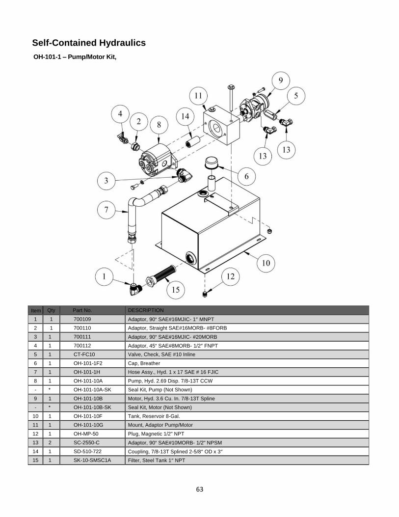
63
Self-Contained Hydraulics
OH-101-1 – Pump/Motor Kit,
Item Qty Part No. DESCRIPTION
1 1 700109 Adaptor, 90° SAE#16MJIC- 1” MNPT
2 1 700110 Adaptor, Straight SAE#16MORB- #8FORB
3 1 700111 Adaptor, 90° SAE#16MJIC- #20MORB
4 1 700112 Adaptor, 45° SAE#8MORB- 1/2” FNPT
5 1 CT-FC10 Valve, Check, SAE #10 Inline
6 1 OH-101-1F2 Cap, Breather
7 1 OH-101-1H Hose Assy., Hyd. 1 x 17 SAE # 16 FJIC
8 1 OH-101-10A Pump, Hyd. 2.69 Disp. 7/8-13T CCW
- * OH-101-10A-SK Seal Kit, Pump (Not Shown)
9 1 OH-101-10B Motor, Hyd. 3.6 Cu. In. 7/8-13T Spline
- * OH-101-10B-SK Seal Kit, Motor (Not Shown)
10 1 OH-101-10F Tank, Reservoir 8-Gal.
11 1 OH-101-10G Mount, Adaptor Pump/Motor
12 1 OH-MP-50 Plug, Magnetic 1/2" NPT
13 2 SC-2550-C Adaptor, 90° SAE#10MORB- 1/2" NPSM
14 1 SD-510-722 Coupling, 7/8-13T Splined 2-5/8” OD x 3”
15 1 SK-10-SMSC1A Filter, Steel Tank 1” NPT
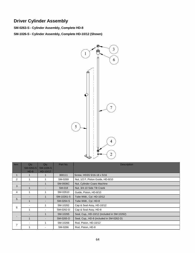
64
Driver Cylinder Assembly
SM-0263-S - Cylinder Assembly, Complete HD-8
SM-1026-S - Cylinder Assembly, Complete HD-10/12 (Shown)
Item Qty.
SM-0263-S
HD-8
Qty.
SM-1026-S
HD-10/12
Part No. Description
1 1 1 300111 Screw, HSSS 5/16-18 x 5/16
2 1 1 SM-0269 Nut, 1/2 F. Piston Guide, HD-8/10
3 - 1 SM-0936C Nut, Cylinder Coars Machine
1 - SM-018 Nut, 3/4-10 Side Tilt Crank
4 1 1 SM-02610 Guide, Piston, HD-8/10
5 - 1 SM-10261-S Tube Wldt., Cyl. HD-10/12
1 - SM-0264-S Tube Wldt., Cyl. HD-8
6 - 1 SM-10262 Cap & Seal Assy, HD-10/12
1 - SM-0262-D Cap & Seal Assy, HD-8
- - 1 SM-10265 Seal, Cup,, HD-10/12 (included in SM-10262)
1 - SM-0265-D Seal, Cup,, HD-8 (included in SM-0262-D)
7 - 1 SM-10266 Rod, Piston, HD-10/12
1 - SM-0266 Rod, Piston, HD-8
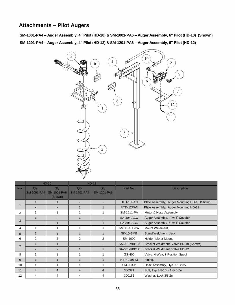
65
Attachments – Pilot Augers
SM-1001-PA4 – Auger Assembly, 4” Pilot (HD-10) & SM-1001-PA6 – Auger Assembly, 6” Pilot (HD-10) (Shown)
SM-1201-PA4 – Auger Assembly, 4” Pilot (HD-12) & SM-1201-PA6 – Auger Assembly, 6” Pilot (HD-12)
HD-10 HD-12
Item Qty.
SM-1001-PA4
Qty.
SM-1001-PA6
(Shown)
Qty.
SM-1201-PA4
Qty.
SM-1201-PA6
Part No. Description
1 1 1 - - UTD-10PAN Plate Assembly, Auger Mounting HD-10 (Shown)
- - 1 1 UTD-12PAN Plate Assembly, Auger Mounting HD-12
2 1 1 1 1 SM-1011-PA Motor & Hose Assembly
3 1 - 1 - SA-304-ACC Auger Assembly, 4” w/1” Coupler
- 1 - 1 SA-306-ACC Auger Assembly, 6” w/1” Coupler
4 1 1 1 1 SM-1100-PAW Mount Weldment,
5 1 1 1 1 SK-10-SMB Stand Weldment, Jack
6 2 2 2 2 SM-1000 Holder, Motor Mount
7 1 1 - - SA-001-VBP10 Bracket Weldment, Valve HD-10 (Shown)
- - 1 1 SA-001-VBP12 Bracket Weldment, Valve HD-12
8 1 1 1 1 GS-400 Valve, 4-Way, 3-Position Spool
9 1 1 1 1 HBP-910183 Fitting,
10 1 1 1 1 SM-023-P Hose Assembly, Hyd. 1/2 x 35
11 4 4 4 4 300321 Bolt, Tap 3/8-16 x 1 Gr5 Zn
12 4 4 4 4 300182 Washer, Lock 3/8 Zn
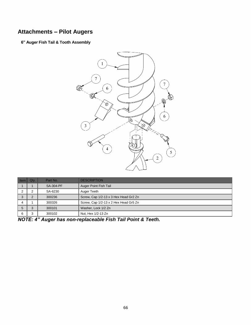
66
Attachments – Pilot Augers
6” Auger Fish Tail & Tooth Assembly
Item Qty. Part No. DESCRIPTION
1 1 SA-304-PF Auger Point Fish Tail
2 2 SA-6230 Auger Teeth
3 2 300236 Screw, Cap 1/2-13 x 3 Hex Head Gr2 Zn
4 1 300326 Screw, Cap 1/2-13 x 2 Hex Head Gr5 Zn
5 3 300101 Washer, Lock 1/2 Zn
6 3 300102 Nut, Hex 1/2-13 Zn
NOTE: 4” Auger has non-replaceable Fish Tail Point & Teeth.
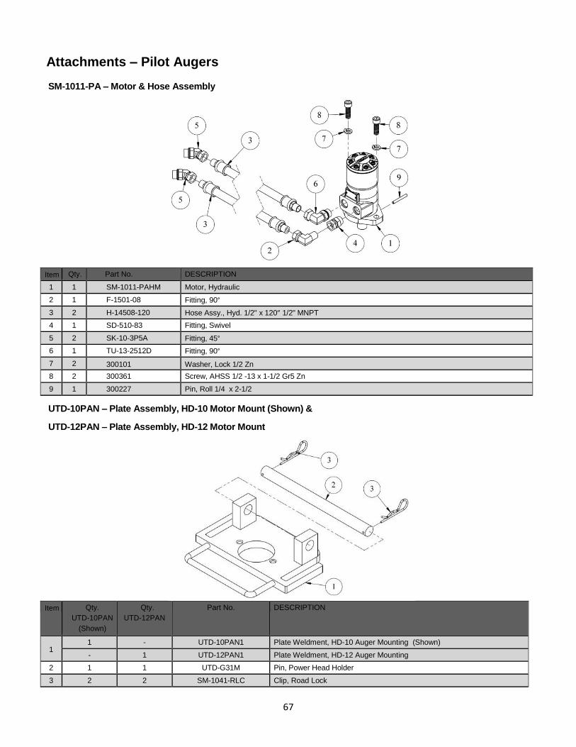
67
Attachments – Pilot Augers
SM-1011-PA – Motor & Hose Assembly
Item Qty. Part No. DESCRIPTION
1 1 SM-1011-PAHM Motor, Hydraulic
2 1 F-1501-08 Fitting, 90°
3 2 H-14508-120 Hose Assy., Hyd. 1/2" x 120” 1/2" MNPT
4 1 SD-510-83 Fitting, Swivel
5 2 SK-10-3P5A Fitting, 45°
6 1 TU-13-2512D Fitting, 90°
7 2 300101 Washer, Lock 1/2 Zn
8 2 300361 Screw, AHSS 1/2 -13 x 1-1/2 Gr5 Zn
9 1 300227 Pin, Roll 1/4 x 2-1/2
UTD-10PAN – Plate Assembly, HD-10 Motor Mount (Shown) &
UTD-12PAN – Plate Assembly, HD-12 Motor Mount
Item Qty.
UTD-10PAN
(Shown)
Qty.
UTD-12PAN
Part No. DESCRIPTION
1 1 - UTD-10PAN1 Plate Weldment, HD-10 Auger Mounting (Shown)
- 1 UTD-12PAN1 Plate Weldment, HD-12 Auger Mounting
2 1 1 UTD-G31M Pin, Power Head Holder
3 2 2 SM-1041-RLC Clip, Road Lock
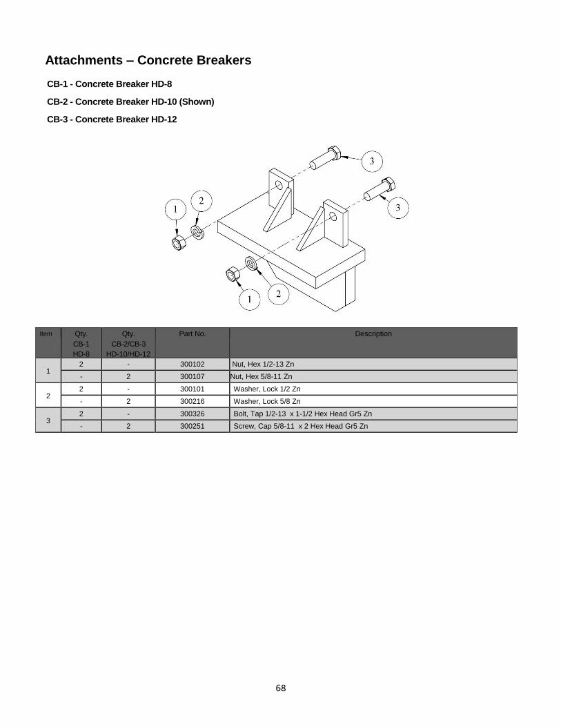
68
Attachments – Concrete Breakers
CB-1 - Concrete Breaker HD-8
CB-2 - Concrete Breaker HD-10 (Shown)
CB-3 - Concrete Breaker HD-12
Item Qty.
CB-1
HD-8
Qty.
CB-2/CB-3
HD-10/HD-12
Part No. Description
1 2 - 300102 Nut, Hex 1/2-13 Zn
- 2 300107 Nut, Hex 5/8-11 Zn
2 2 - 300101 Washer, Lock 1/2 Zn
- 2 300216 Washer, Lock 5/8 Zn
3 2 - 300326 Bolt, Tap 1/2-13 x 1-1/2 Hex Head Gr5 Zn
- 2 300251 Screw, Cap 5/8-11 x 2 Hex Head Gr5 Zn
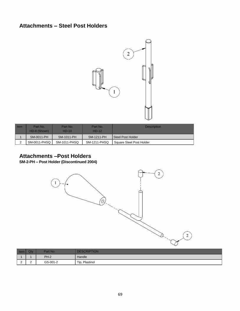
69
Attachments – Steel Post Holders
Item Part No.
HD-8 (Shown)
Part No.
HD-10
Part No.
HD-12
Description
1 SM-0011-PH SM-1011-PH SM-1211-PH Steel Post Holder
2 SM-0011-PHSQ SM-1011-PHSQ SM-1211-PHSQ Square Steel Post Holder
Attachments –Post Holders SM-2-PH – Post Holder (Discontinued 2004)
Item Qty Part No. DESCRIPTION
1 1 PH-2 Handle
2 2 GS-001-2 Tip, Plastinol
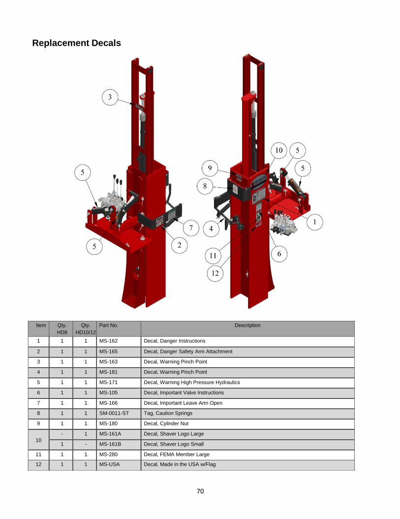
70
Replacement Decals
Item Qty.
HD8
Qty.
HD10/12
Part No. Description
1 1 1 MS-162 Decal, Danger Instructions
2 1 1 MS-165 Decal, Danger Safety Arm Attachment
3 1 1 MS-163 Decal, Warning Pinch Point
4 1 1 MS-181 Decal, Warning Pinch Point
5 1 1 MS-171 Decal, Warning High Pressure Hydraulics
6 1 1 MS-105 Decal, Important Valve Instructions
7 1 1 MS-166 Decal, Important Leave Arm Open
8 1 1 SM-0011-ST Tag, Caution Springs
9 1 1 MS-180 Decal, Cylinder Nut
10
- 1 MS-161A Decal, Shaver Logo Large
1 - MS-161B Decal, Shaver Logo Small
11 1 1 MS-280 Decal, FEMA Member Large
12 1 1 MS-USA Decal, Made in the USA w/Flag

71
Shaver Manufacturing Co., LLC. 103 South Washington Avenue
P.O. Box 358 Graettinger, IA 51342
Phone: (712) 859-3293 Fax: (712) 859-3294
Limited Warranty Shaver Manufacturing Company, LLC warrants each new Shaver product to be free from defects in material and workmanship. This warranty is applicable only for the normal service life expectancy of the product or components, not to exceed 12 consecutive months from the date of delivery of the new Shaver product to the original purchaser.
Genuine Shaver replacement parts and components will be warranted for 90 days from the date of purchase, or the remainder of the original equipment warranty period, whichever is longer.
Rubber Bumpers, Carbide Teeth, Auger Teeth and Auger Points are usable parts and not covered by warranty. Part No. SD-101-GB and SD-0301-GB Gearbox are warranted for 3 years from the date of purchase. Part No. SD-0607-GB and SD-0907-GB Gearbox are warranted for 5 years from the date of purchase. Driving Ram Springs are warranted for 60 days from the date of purchase for residential customers and 30 days from the date of purchase with a limit of 2 claims per serial numbered unit for commercial users. Tires are warranted for 90 days from the date of purchase. Replacement parts come with a 90 day warranty from date of purchase.
Under no circumstances will it cover any merchandise or components thereof, which, in the opinion of the company, have been subjected to misuse, unauthorized modification, alteration, an accident, or if a repair has been made with parts other than those obtainable through Shaver.
Our obligation under this warranty shall be limited to repairing or replacing any part that, in our judgment, shall show evidence of such defect, provided further that such part shall be returned within thirty (30) days from the date of failure to Shaver, routed through the dealer and distributor from whom the purchase was made, transportation charges prepaid. All returned items must have an RGA number. Contact Shaver at 712-859-3293 to get authorization to return, file your warranty claim and, if needed, an RGA will be provided.
This warranty shall not be interpreted to render Shaver liable for injury or damages of any kind or nature to person or property. This warranty does not extend to the loss of crops, loss because of delay in harvesting, or any expense or loss incurred for labor, substitute machinery, rental, or for any other reason.
Except as set forth above, Shaver shall have no obligation or liability of any kind on account of any of its equipment and shall not be liable for special or consequential damages. Shaver makes no other warranty, expressed or implied, and specifically, Shaver disclaims any implied warranty of merchantability or fitness for a particular purpose. Some states or provinces do not permit limitations or exclusions of implied warranties or incidental or consequential damages, so the limitations or exclusion in this warranty may not apply.
This warranty is subject to any existing conditions of supply which may directly affect our ability to obtain materials or manufacture replacement parts.
Shaver reserves the right to make improvements in design or changes in specifications at any time, without incurring any obligation to owners of units previously sold.
No one is authorized to alter, modify, or enlarge this warranty, nor the exclusion, limitations, and reservations.
Effective January 1, 2015

72
This page left intentionally blank.

73
Warranty Card The Post Driver is shipped from the factory with a warranty card. If the card is lost or misplaced, please copy this page, fill in the information, and send it to Shaver Manufacturing Company.
Warranty Card
Please complete the warranty card and return to:
Shaver Manufacturing Company 103 South Washington Avenue
P.O. Box 358 Graettinger, Iowa 51342
Name
Address
City State Zip Code
Purchase / Delivery Date
Shaver Model Number
Serial Number
Serial Number
Dealer___________________________________________

74
This page left intentionally blank.

75
This page left intentionally blank.

76
SHAVER Post Drivers July 2015