Embed Size (px)
Citation preview
HCS12 Technical Training Module 16- Debug Interface, Slide 1
MOTOROLA and the Stylized M Logo are registered in the US Patent & Trademark Office. All other product or service names are the property of their respective owners. © Motorola, Inc. 2001.
Debug Module
(BDM)
HCS12 Technical Training Module 16- Debug Interface, Slide 2
MOTOROLA and the Stylized M Logo are registered in the US Patent & Trademark Office. All other product or service names are the property of their respective owners. © Motorola, Inc. 2001.
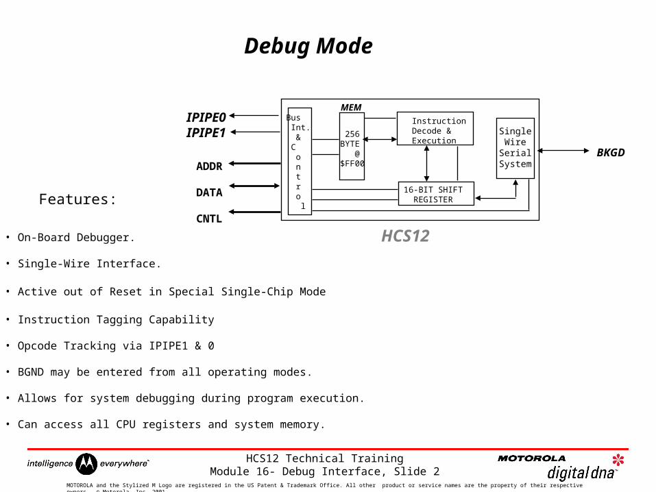
Debug Mode
Features:
• On-Board Debugger.
• Single-Wire Interface.
• Active out of Reset in Special Single-Chip Mode
• Instruction Tagging Capability
• Opcode Tracking via IPIPE1 & 0
• BGND may be entered from all operating modes.
• Allows for system debugging during program execution.
• Can access all CPU registers and system memory.
IPIPE0IPIPE1
BKGD
Single WireSerialSystem
16-BIT SHIFT REGISTER
InstructionDecode & Execution
256BYTE @$FF00
MEM
ADDR
DATA
CNTL
Bus Int. & C o n t r o l
HCS12
HCS12 Technical Training Module 16- Debug Interface, Slide 3
MOTOROLA and the Stylized M Logo are registered in the US Patent & Trademark Office. All other product or service names are the property of their respective owners. © Motorola, Inc. 2001.
Background Debug Mode
Background debug mode (BDM) is an auxiliary operating mode that isused for system development. BDM is implemented in on-chip hardwareand provides a full set of debug operations. Some BDM commands canbe executed while the CPU is operating normally. Other BDMcommands are firmware based, and require the BDM firmware to beenabled and active for execution.
In special single-chip mode, BDM is enabled and active immediately outof reset. BDM is available in all other operating modes, but must beenabled before it can be activated. BDM should not be used in specialperipheral mode because of potential bus conflicts.
HCS12 Technical Training Module 16- Debug Interface, Slide 4
MOTOROLA and the Stylized M Logo are registered in the US Patent & Trademark Office. All other product or service names are the property of their respective owners. © Motorola, Inc. 2001.
Background Debug Mode
Once enabled, background mode can be made active by a serialcommand sent via the BKGD pin or execution of a CPU12 BGNDinstruction. While background mode is active, the CPU can interpretspecial debugging commands, and read and write CPU registers,peripheral registers, and locations in memory.
While BDM is active, the CPU executes code located in a small on-chipROM mapped to addresses $FF20 to $FFFF, and BDM control registersare accessible at addresses $FF00 to $FF06. The BDM ROM replacesthe regular system vectors while BDM is active. While BDM is active, theuser memory from $FF00 to $FFFF is not in the map except throughserial BDM commands.
HCS12 Technical Training Module 16- Debug Interface, Slide 5
MOTOROLA and the Stylized M Logo are registered in the US Patent & Trademark Office. All other product or service names are the property of their respective owners. © Motorola, Inc. 2001.
HCS12
Target System
BDM Interface Pod
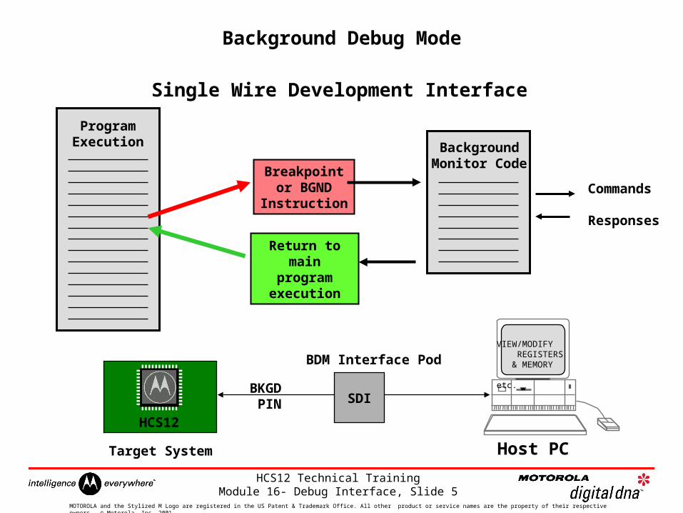
ProgramExecution Background
Monitor Code
Commands
Responses
Breakpoint or BGND Instruction
Return tomain program
execution
BKGD PIN SDI
Background Debug Mode
Host PC
VIEW/MODIFY REGISTERS & MEMORY etc.
Single Wire Development Interface
HCS12 Technical Training Module 16- Debug Interface, Slide 6
MOTOROLA and the Stylized M Logo are registered in the US Patent & Trademark Office. All other product or service names are the property of their respective owners. © Motorola, Inc. 2001.
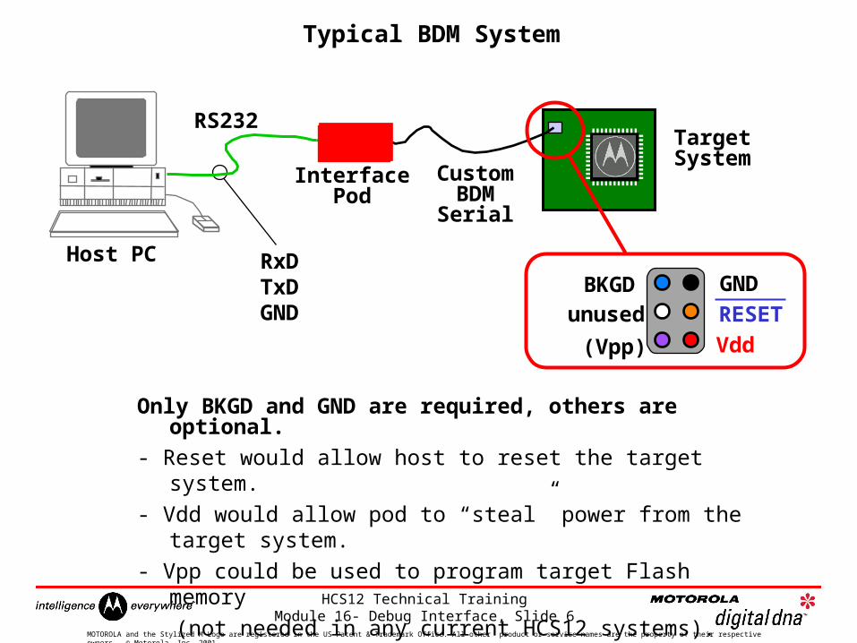
Typical BDM System
Only BKGD and GND are required, others are optional.
- Reset would allow host to reset the target system.
- Vdd would allow pod to “steal” power from the target system.
- Vpp could be used to program target Flash memory
(not needed in any current HCS12 systems).
Host PC
RS232
RxDTxDGND
InterfacePod
CustomBDMSerial
TargetSystem
BKGDunused
(Vpp)
GND
Vdd
RESET
HCS12 Technical Training Module 16- Debug Interface, Slide 7
MOTOROLA and the Stylized M Logo are registered in the US Patent & Trademark Office. All other product or service names are the property of their respective owners. © Motorola, Inc. 2001.
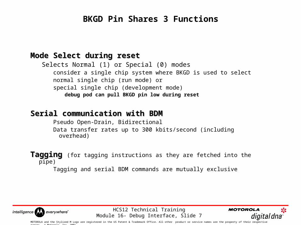
BKGD Pin Shares 3 Functions
Mode Select during resetMode Select during resetSelects Normal (1) or Special (0) modes
consider a single chip system where BKGD is used to selectnormal single chip (run mode) orspecial single chip (development mode)
debug pod can pull BKGD pin low during reset
Serial communication with BDMSerial communication with BDMPseudo Open-Drain, BidirectionalData transfer rates up to 300 kbits/second (including overhead)
Tagging Tagging (for tagging instructions as they are fetched into the pipe)
Tagging and serial BDM commands are mutually exclusive
HCS12 Technical Training Module 16- Debug Interface, Slide 8
MOTOROLA and the Stylized M Logo are registered in the US Patent & Trademark Office. All other product or service names are the property of their respective owners. © Motorola, Inc. 2001.
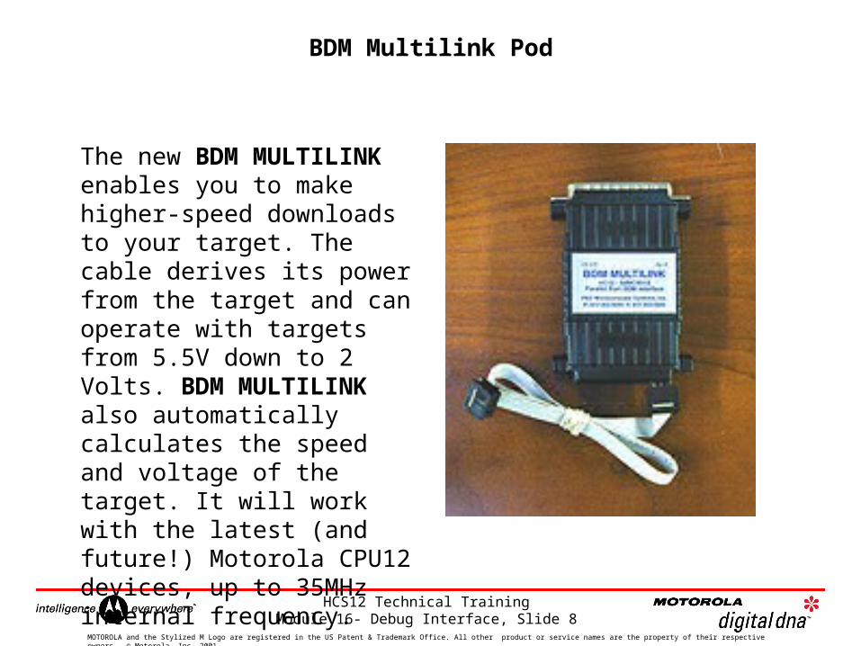
BDM Multilink Pod
The new BDM MULTILINK enables you to make higher-speed downloads to your target. The cable derives its power from the target and can operate with targets from 5.5V down to 2 Volts. BDM MULTILINK also automatically calculates the speed and voltage of the target. It will work with the latest (and future!) Motorola CPU12 devices, up to 35MHz internal frequency.
HCS12 Technical Training Module 16- Debug Interface, Slide 9
MOTOROLA and the Stylized M Logo are registered in the US Patent & Trademark Office. All other product or service names are the property of their respective owners. © Motorola, Inc. 2001.
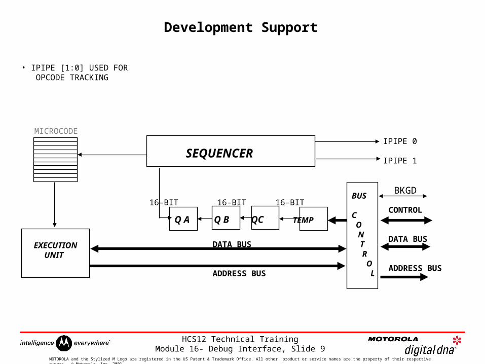
Development Support
MICROCODE
SEQUENCER
EXECUTION UNIT
Q A Q B QC TEMPCONTROL
DATA BUS
ADDRESS BUS
DATA BUS
ADDRESS BUS
BUS
C O N T R O L
IPIPE 0
IPIPE 1
• IPIPE [1:0] USED FOR OPCODE TRACKING
16-BIT 16-BIT 16-BIT
BKGD
HCS12 Technical Training Module 16- Debug Interface, Slide 10
MOTOROLA and the Stylized M Logo are registered in the US Patent & Trademark Office. All other product or service names are the property of their respective owners. © Motorola, Inc. 2001.
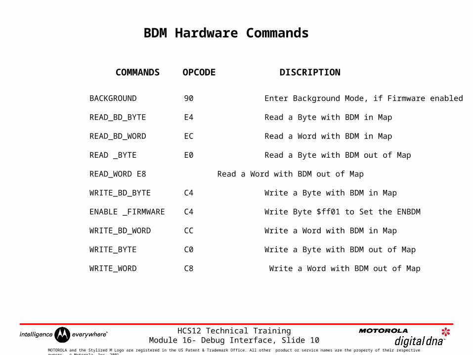
BDM Hardware Commands
BACKGROUND 90 Enter Background Mode, if Firmware enabled
READ_BD_BYTE E4 Read a Byte with BDM in Map
READ_BD_WORD EC Read a Word with BDM in Map
READ _BYTE E0 Read a Byte with BDM out of Map
READ_WORD E8 Read a Word with BDM out of Map
WRITE_BD_BYTE C4 Write a Byte with BDM in Map
ENABLE _FIRMWARE C4 Write Byte $ff01 to Set the ENBDM
WRITE_BD_WORD CC Write a Word with BDM in Map
WRITE_BYTE C0 Write a Byte with BDM out of Map
WRITE_WORD C8 Write a Word with BDM out of Map
COMMANDS OPCODE DISCRIPTION
HCS12 Technical Training Module 16- Debug Interface, Slide 11
MOTOROLA and the Stylized M Logo are registered in the US Patent & Trademark Office. All other product or service names are the property of their respective owners. © Motorola, Inc. 2001.
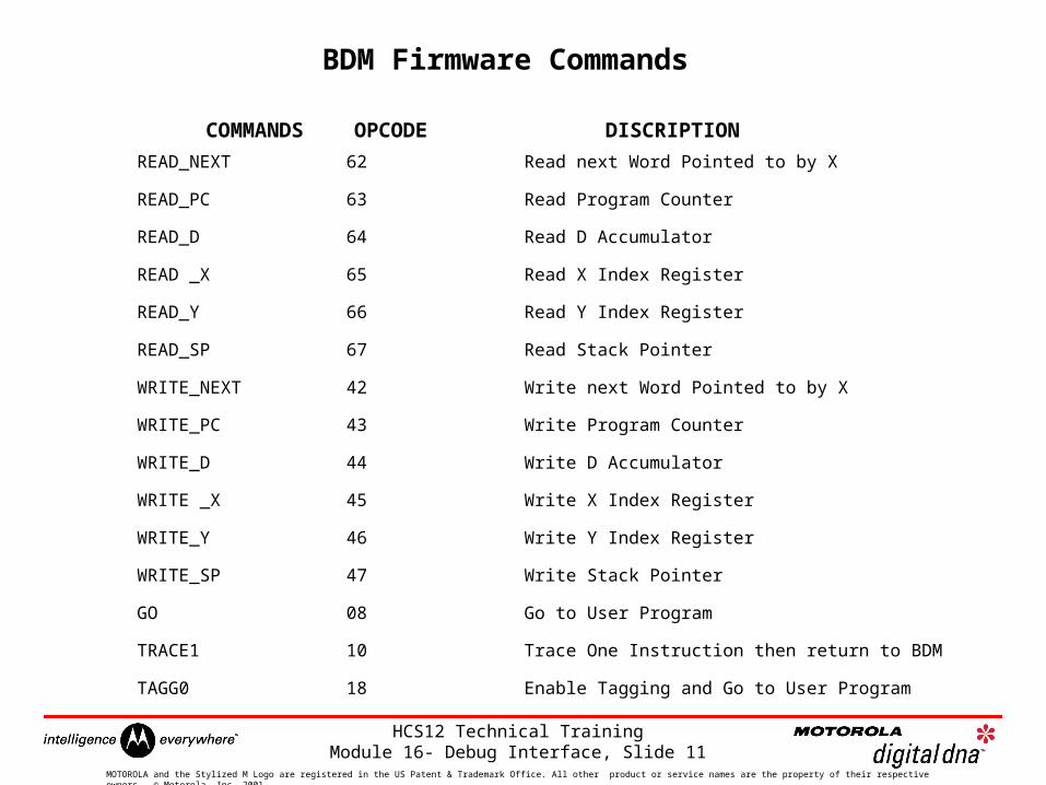
BDM Firmware Commands
READ_NEXT 62 Read next Word Pointed to by X
READ_PC 63 Read Program Counter
READ_D 64 Read D Accumulator
READ _X 65 Read X Index Register
READ_Y 66 Read Y Index Register
READ_SP 67 Read Stack Pointer
WRITE_NEXT 42 Write next Word Pointed to by X
WRITE_PC 43 Write Program Counter
WRITE_D 44 Write D Accumulator
WRITE _X 45 Write X Index Register
WRITE_Y 46 Write Y Index Register
WRITE_SP 47 Write Stack Pointer
GO 08 Go to User Program
TRACE1 10 Trace One Instruction then return to BDM
TAGG0 18 Enable Tagging and Go to User Program
COMMANDS OPCODE DISCRIPTION
HCS12 Technical Training Module 16- Debug Interface, Slide 12
MOTOROLA and the Stylized M Logo are registered in the US Patent & Trademark Office. All other product or service names are the property of their respective owners. © Motorola, Inc. 2001.
BDM Conclusions
Much simpler connections than Logic Analyzers or Clip-Over Emulators- Less Cost- Allows Debug Under REAL Operating Conditions- No Need to Turn Off System to Connect to BDM
Read/Write Access Without Disturbing the Running Programs
Can Implement a Complete Debug Monitor
BDM Used for More Than Just Debug- Program system memory (EEPROM, Flash, RAM, external memory devices)- Product maintenance without disassembly- Calibration and monitoring system operation (non-intrusively)- Read out error codes to help technicians locate difficult problems
HCS12 Technical Training Module 16- Debug Interface, Slide 13
MOTOROLA and the Stylized M Logo are registered in the US Patent & Trademark Office. All other product or service names are the property of their respective owners. © Motorola, Inc. 2001.
VDD
RESET
GND
BKGD
VFP
unused
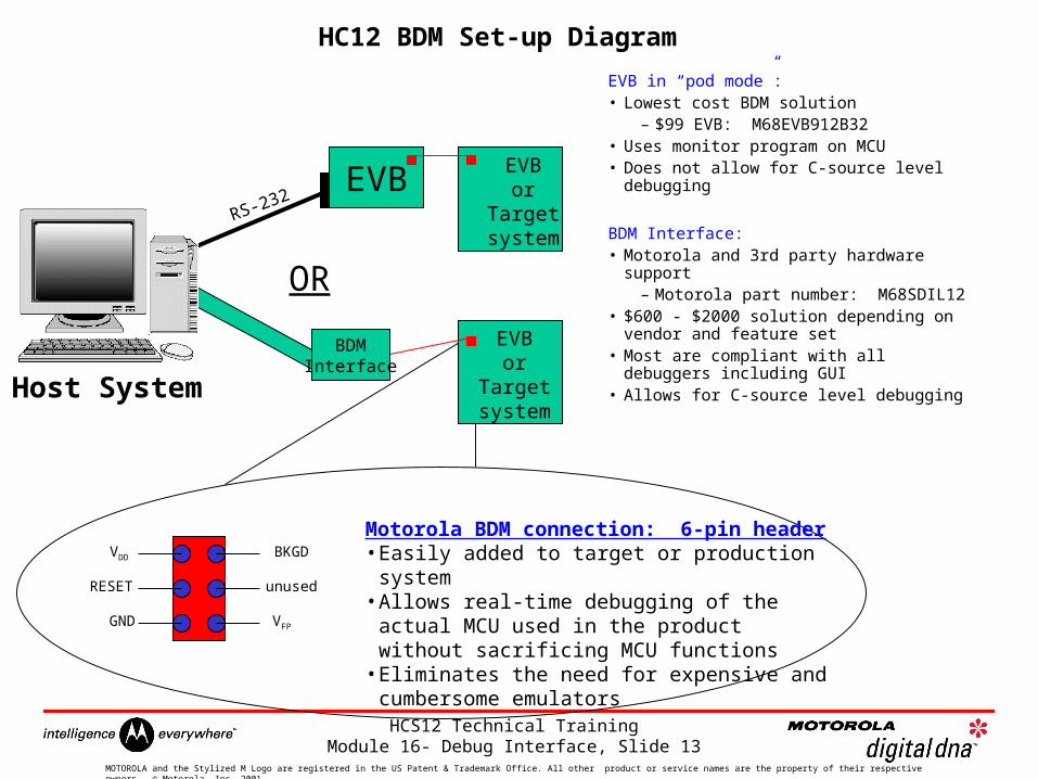
Motorola BDM connection: 6-pin header• Easily added to target or production system• Allows real-time debugging of the actual MCU used in
the product without sacrificing MCU functions• Eliminates the need for expensive and cumbersome
emulators
EVB in “pod mode”:• Lowest cost BDM solution
– $99 EVB: M68EVB912B32• Uses monitor program on MCU• Does not allow for C-source level
debugging
BDM Interface:• Motorola and 3rd party hardware support
– Motorola part number: M68SDIL12• $600 - $2000 solution depending on
vendor and feature set• Most are compliant with all debuggers
including GUI• Allows for C-source level debugging
EVBor
Targetsystem
RS-232EVB
BDMInterface
Host System
EVBor
Targetsystem
OR
HC12 BDM Set-up Diagram
HCS12 Technical Training Module 16- Debug Interface, Slide 14
MOTOROLA and the Stylized M Logo are registered in the US Patent & Trademark Office. All other product or service names are the property of their respective owners. © Motorola, Inc. 2001.
HCS12
Development Tools
HCS12 Technical Training Module 16- Debug Interface, Slide 15
MOTOROLA and the Stylized M Logo are registered in the US Patent & Trademark Office. All other product or service names are the property of their respective owners. © Motorola, Inc. 2001.
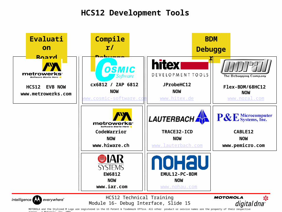
HCS12 Development Tools
Compiler/
Debugger
cx6812 / ZAP 6812
NOW
www.cosmic-software.com
BDM
Debugger
JProbeHC12
NOW
www.hitex.de
TRACE32-ICD
NOW
www.lauterbach.com
EMUL12-PC-BDMNOW
www.nohau.com
Flex-BDM/68HC12 NOW
www.noral.com
CABLE12
NOW
www.pemicro.com
EW6812NOW
www.iar.com
CodeWarrior
NOW
www.hiware.ch
HCS12 EVB NOW
www.metrowerks.com
Evaluation
Board
HCS12 Technical Training Module 16- Debug Interface, Slide 16
MOTOROLA and the Stylized M Logo are registered in the US Patent & Trademark Office. All other product or service names are the property of their respective owners. © Motorola, Inc. 2001.
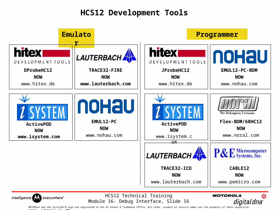
HCS12 Development Tools
Programmer
JProbeHC12
NOW
www.hitex.de
TRACE32-ICD
NOW
www.lauterbach.com
Emulator
DProbeHC12
NOW
www.hitex.de
TRACE32-FIRE
NOW
www.lauterbach.com
ActivePODNOW
www.isystem.com
EMUL12-PC-BDM
NOW
www.nohau.com
Flex-BDM/68HC12
NOW
www.noral.com
CABLE12
NOW
www.pemicro.com
EMUL12-PC
NOW
www.nohau.com
ActivePODNOW
www.isystem.com
HCS12 Technical Training Module 16- Debug Interface, Slide 17
MOTOROLA and the Stylized M Logo are registered in the US Patent & Trademark Office. All other product or service names are the property of their respective owners. © Motorola, Inc. 2001.
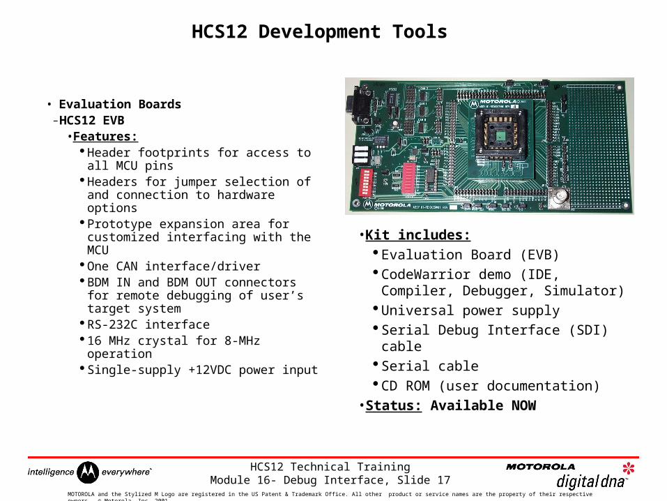
HCS12 Development Tools
• Evaluation Boards– HCS12 EVB
• Features: Header footprints for access to all
MCU pins Headers for jumper selection of and
connection to hardware options Prototype expansion area for
customized interfacing with the MCU One CAN interface/driver BDM IN and BDM OUT connectors
for remote debugging of user’s target system
RS-232C interface 16 MHz crystal for 8-MHz operation Single-supply +12VDC power input
• Kit includes: Evaluation Board (EVB) CodeWarrior demo (IDE, Compiler,
Debugger, Simulator) Universal power supply Serial Debug Interface (SDI) cable Serial cable CD ROM (user documentation)
• Status: Available NOW
HCS12 Technical Training Module 16- Debug Interface, Slide 18
MOTOROLA and the Stylized M Logo are registered in the US Patent & Trademark Office. All other product or service names are the property of their respective owners. © Motorola, Inc. 2001.
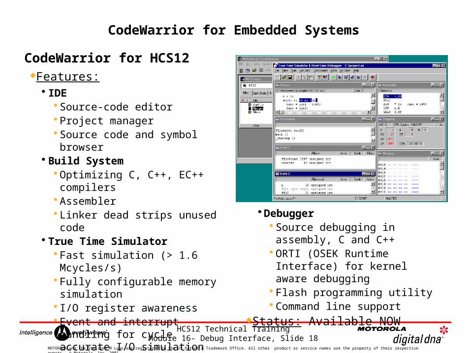
CodeWarrior for HCS12Features:
IDE Source-code editor Project manager Source code and symbol browser
Build System Optimizing C, C++, EC++ compilers
Assembler Linker dead strips unused code
True Time Simulator Fast simulation (> 1.6 Mcycles/s)
Fully configurable memory simulation
I/O register awareness Event and interrupt handling for cycle accurate I/O simulation
Time measuring, coverage and profiling analysis
Debugger Source debugging in assembly, C and C++
ORTI (OSEK Runtime Interface) for kernel aware debugging
Flash programming utility Command line support
Status: Available NOW
CodeWarrior for Embedded Systems
HCS12 Technical Training Module 16- Debug Interface, Slide 19
MOTOROLA and the Stylized M Logo are registered in the US Patent & Trademark Office. All other product or service names are the property of their respective owners. © Motorola, Inc. 2001.
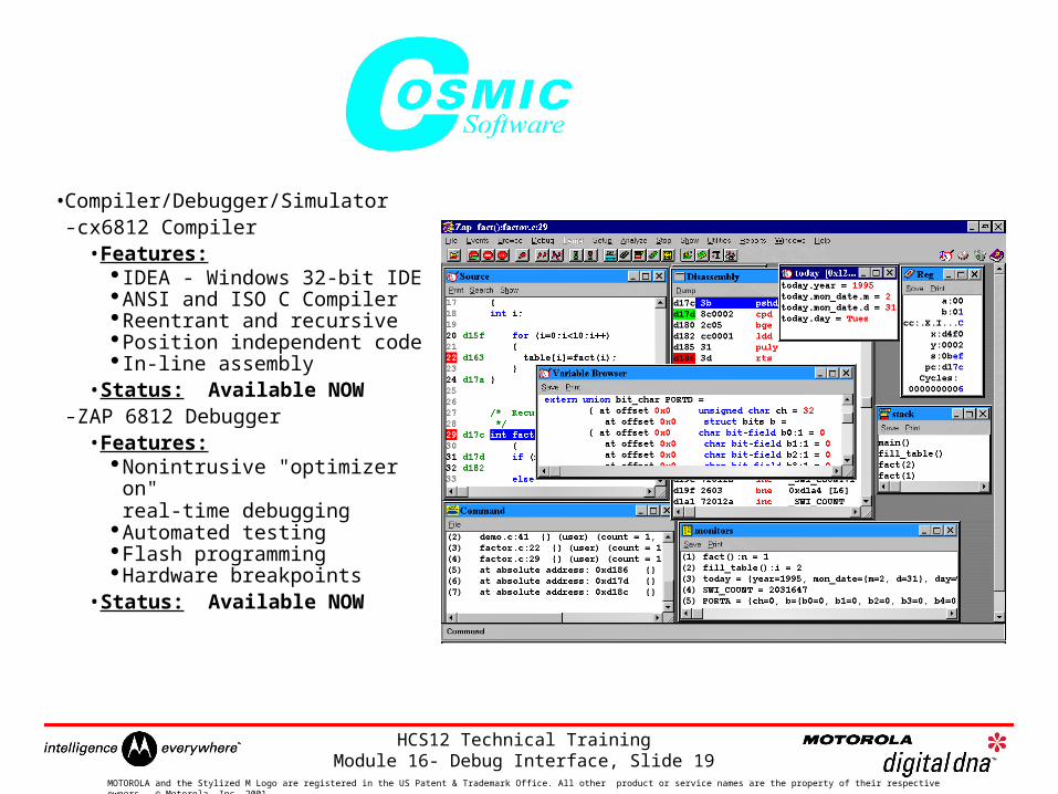
•Compiler/Debugger/Simulator– cx6812 Compiler
• Features: IDEA - Windows 32-bit IDEANSI and ISO C CompilerReentrant and recursivePosition independent code In-line assembly
•Status: Available NOW– ZAP 6812 Debugger
• Features:Nonintrusive "optimizer on"
real-time debuggingAutomated testingFlash programmingHardware breakpoints
•Status: Available NOW
HCS12 Technical Training Module 16- Debug Interface, Slide 20
MOTOROLA and the Stylized M Logo are registered in the US Patent & Trademark Office. All other product or service names are the property of their respective owners. © Motorola, Inc. 2001.
•Embedded Workbench EW6812– C Compiler
• Features:Highly efficient and PROMable code. Full ANSI C compatibility. Built-in chip-specific size and speed
optimizer. Target specific extensions. Choice of memory models.
•Status: Available NOW– C-SPY Simulator debugger
• Features:Supports all levels of debugging with
complex breakpoints.Debugging on C-source and assembly
source levels.Profiler for bottleneck analysis.Code coverage.
•Status: Available NOW
HCS12 Technical Training Module 16- Debug Interface, Slide 21
MOTOROLA and the Stylized M Logo are registered in the US Patent & Trademark Office. All other product or service names are the property of their respective owners. © Motorola, Inc. 2001.
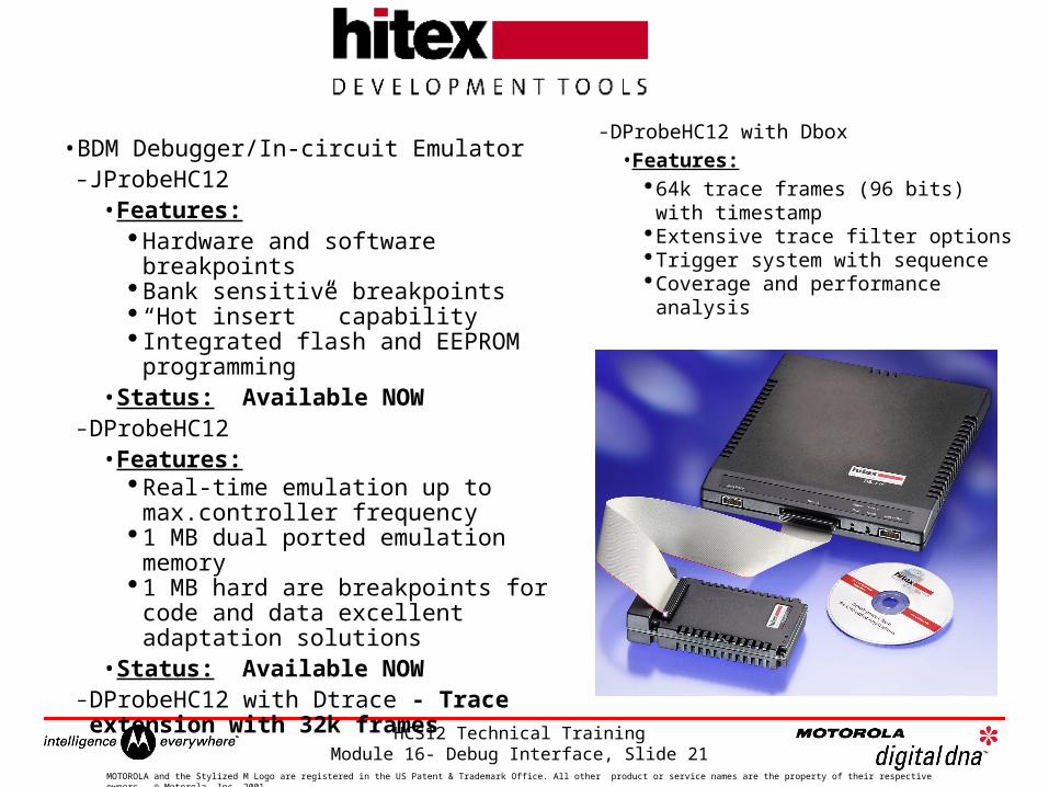
•BDM Debugger/In-circuit Emulator– JProbeHC12
• Features: Hardware and software breakpoints Bank sensitive breakpoints “Hot insert ” capability Integrated flash and EEPROM programming
•Status: Available NOW– DProbeHC12
• Features:Real-time emulation up to max.controller frequency
1 MB dual ported emulation memory1 MB hard are breakpoints for code and data excellent adaptation solutions
•Status: Available NOW– DProbeHC12 with Dtrace - Trace extension with
32k frames
– DProbeHC12 with Dbox
• Features:64k trace frames (96 bits) with
timestampExtensive trace filter optionsTrigger system with sequenceCoverage and performance analysis
HCS12 Technical Training Module 16- Debug Interface, Slide 22
MOTOROLA and the Stylized M Logo are registered in the US Patent & Trademark Office. All other product or service names are the property of their respective owners. © Motorola, Inc. 2001.
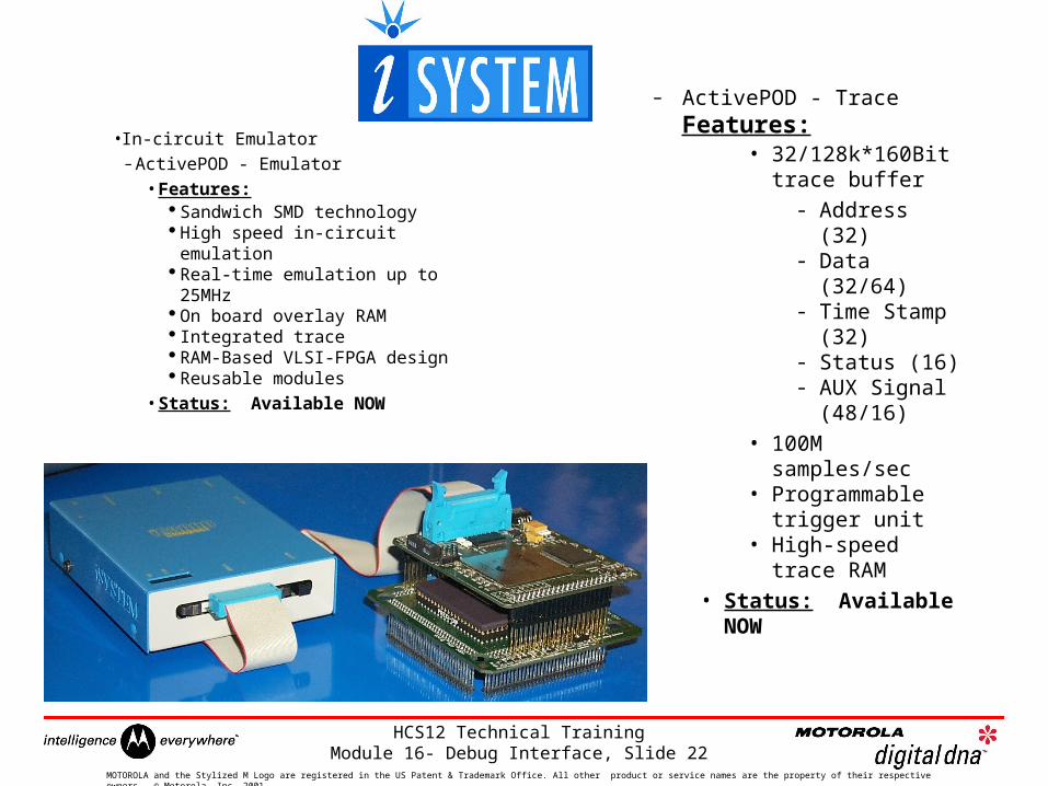
•In-circuit Emulator– ActivePOD - Emulator
• Features: Sandwich SMD technology High speed in-circuit emulation Real-time emulation up to 25MHz On board overlay RAM Integrated trace RAM-Based VLSI-FPGA design Reusable modules
•Status: Available NOW
– ActivePOD - Trace Features:
• 32/128k*160Bit trace buffer
- Address (32)
- Data (32/64)- Time Stamp
(32)- Status (16)- AUX Signal
(48/16)
• 100M samples/sec
• Programmable trigger unit
• High-speed trace RAM
• Status: Available NOW
HCS12 Technical Training Module 16- Debug Interface, Slide 23
MOTOROLA and the Stylized M Logo are registered in the US Patent & Trademark Office. All other product or service names are the property of their respective owners. © Motorola, Inc. 2001.
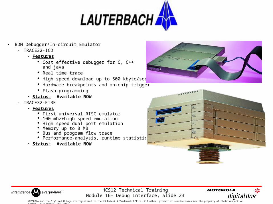
• BDM Debugger/In-circuit Emulator– TRACE32-ICD
• Features Cost effective debugger for C, C++
and java Real time trace High speed download up to 500 kbyte/sec Hardware breakpoints and on-chip trigger Flash-programming
• Status: Available NOW– TRACE32-FIRE
• Features First universal RISC emulator 100 mhz+high speed emulation High speed dual port emulation Memory up to 8 MB Bus and program flow trace Performance-analysis, runtime statistics and code coverage analysis
• Status: Available NOW
HCS12 Technical Training Module 16- Debug Interface, Slide 24
MOTOROLA and the Stylized M Logo are registered in the US Patent & Trademark Office. All other product or service names are the property of their respective owners. © Motorola, Inc. 2001.
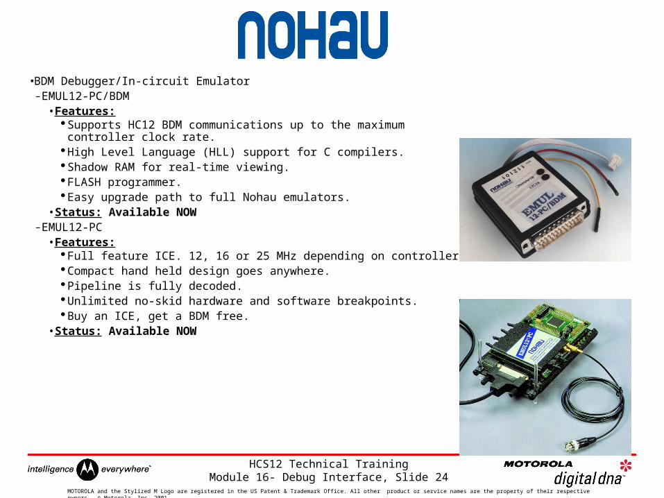
•BDM Debugger/In-circuit Emulator – EMUL12-PC/BDM
• Features:Supports HC12 BDM communications up to the maximum
controller clock rate.High Level Language (HLL) support for C compilers.Shadow RAM for real-time viewing.FLASH programmer. Easy upgrade path to full Nohau emulators.
•Status: Available NOW– EMUL12-PC
• Features:Full feature ICE. 12, 16 or 25 MHz depending on controller.Compact hand held design goes anywhere. Pipeline is fully decoded.Unlimited no-skid hardware and software breakpoints.Buy an ICE, get a BDM free.
•Status: Available NOW
HCS12 Technical Training Module 16- Debug Interface, Slide 25
MOTOROLA and the Stylized M Logo are registered in the US Patent & Trademark Office. All other product or service names are the property of their respective owners. © Motorola, Inc. 2001.
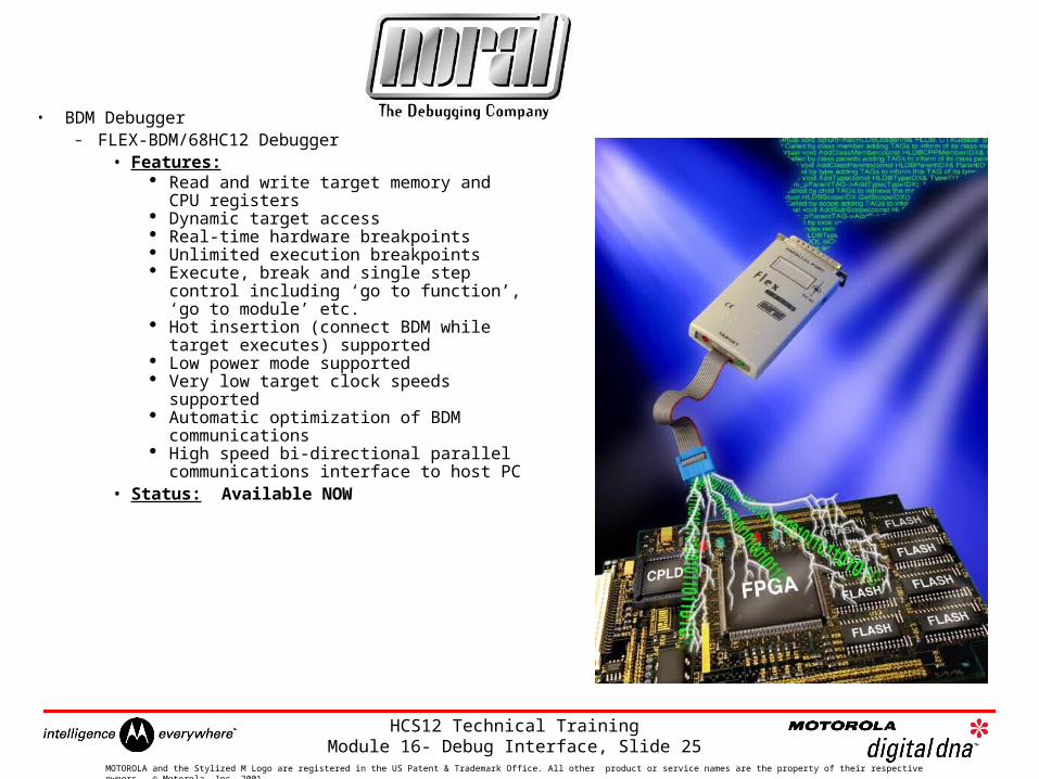
• BDM Debugger– FLEX-BDM/68HC12 Debugger
• Features: Read and write target memory and CPU
registers Dynamic target access Real-time hardware breakpoints Unlimited execution breakpoints Execute, break and single step control
including ‘go to function’, ‘go to module’ etc.
Hot insertion (connect BDM while target executes) supported
Low power mode supported Very low target clock speeds supported Automatic optimization of BDM
communications High speed bi-directional parallel
communications interface to host PC • Status: Available NOW
HCS12 Technical Training Module 16- Debug Interface, Slide 26
MOTOROLA and the Stylized M Logo are registered in the US Patent & Trademark Office. All other product or service names are the property of their respective owners. © Motorola, Inc. 2001.
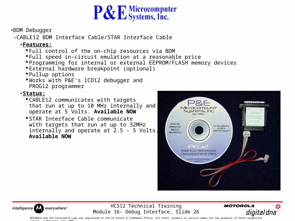
•BDM Debugger–CABLE12 BDM Interface Cable/STAR Interface Cable
• Features:Full control of the on-chip resources via BDM Full speed in-circuit emulation at a reasonable price Programming for internal or external EEPROM/FLASH memory devices External hardware breakpoint (optional) Pullup options Works with P&E's ICD12 debugger and
PROG12 programmer •Status:
CABLE12 communicates with targets that run at up to 10 MHz internally and operate at 5 Volts. Available NOW
STAR Interface Cable communicate with targets that run at up to 32MHzinternally and operate at 2.5 - 5 Volts. Available NOW