Embed Size (px)
Citation preview
ON THE SPOT CHANGEPRINTED 20041212 ' I
IT IS THE RESPONSIBILITY OF THE USER TO VERIFY REVISION, STATUSPRINTED 20041030
I NC.DM-AP.ZZ-0002(Q)
FORM-N1ON-THE-SPOT-CHANGE (OTSC) FORM
PROCEDURE NO: HCPS0. '0&Q OTSC No. S) AOrder No.4 ecs3 vs-s TM1*03-0
PROCEDURE TITLE: 9EArcckrAo, Sysh*w °a, USE CATEGORY:_ .
DESCRIPlION OF CHANt3E' C he A R gtdo- XI C+.T ) k X6eA{ + l¢etphaI -
i/&1ge_ Wt8 PUM27 .7-52-I~,t: 15 T //. 0 - k &
IREASONFORCHANGE: Teivl .4 7h 3-_
LIST PAGES CHANGED: II/ 1(4 , 3!7
Determln6 if the OTSC alters the Intent .of the procedure.Refer to Attachment 1, Change of Intent Criteria. IE.ANY of the statements InAttachment I are true, THENthe OTSC changes the Intent of the procedure...
NC & SH procedurDs: Salem HC Ops SM/ORS signatures required priorto usel
INITIATED: f.R. /tiastlc, (O-3e -05Date
APPROVED:
APPROVEDR
APPROVED
Initiator (Pri
1fM' q A B RI70J4 (' Supervisor (Print 6I1Sfg0)
:p S K15 pr#J)rv P XLflt,-Date
Date1,
/ (Hope Creek) Ops SMlCRS (Print AND Sign) --
(Salom) Ops SMICRS (Print AND Sign) Date
SUPERVISORIDESIGNEE:.1. Initiate a Notification to the responslble procedure group to perform the post-implementation review of
the OTSC upon final Ops SMICRS approval.Notification No: C u~ry.
2. Ptovide an approved cory of the OTSC Package (net the work package) to TDR by the end of shl3. Provide an approved = of the 0TSC Package to the Sponsor/Procedure Writer Iy Itm end of shlk4. When applicable, provide an approved co= of the OTSC Package for the Control Room Console(s).6. Deliver the signed ORIGIN AL OTSO Paokoge for use with the procedure.
Alf S Ensuresacopy of the completed procedure Including the OTSC Package is submnitted wlth the WorkC Package, If the procedure was part of the work package.
COMPLETED BY: _______ 3______ ____ rI,, S48'ivisor/Desibnese Extension - - IC Wte ' I -__
Nuclear Common page II of 14 Rev. 2
USER RESPONSIBLE FOR VERIFYING REVISION, STATUS AND CHANGESPRINTED 20041212
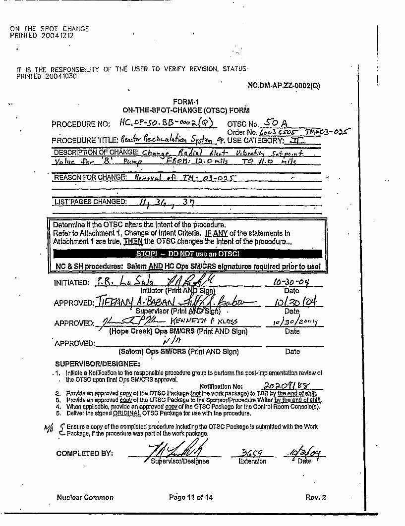
PSEG Internal Use Only Page I of 1PSE G NUCLEAR L.L.C.
HOPE CREEK GENERATING STATION
IIC.OP-SO.BB-0002(Q) - Rev. 50
REACTOR RECIRCULATION SYSTEM OPERATION
USE CATEGORY: II Field Copy Exists
A. Biennial Review performed Yes No V N/A
B. Change Package(s) and Affected Document Number(s) incorporated into this revision.
CPNo. CPRev.No. ADNo. AD Rev.No. orNoine
C. OTSC(s) incorporated into this revision:
O . TSC No(s) . orNone V
REVISION SUMMARY,
I. Based on the requests made under orders 70038946 and 80071310, prerequisite 2.1.14 has beenre-worded to clarify that the .MG Set Fluid Coupler Oil Level should be f 1/4 inch of theMaximum level mark prior to starting the MG Set, and that the level will lower as MG Speed israised.
2. Based on the requests made under orders 70038946 and 80071310, new Precaution 3.1.31 hasbeen added to this revision to clarify where the oil level should be maintained in the MG Set FluidCoupler, for different conditions of operation.
3. Added PNI-B31-SO01-0120 to the reference section of the procedure. This change is editorial innature, based on the guidance found inNC.NA-AP.ZZ-000I(Q).
A/c5/-/
IMPLEMENTATION REOUIREMENTS Effective date 0|
The MG Set Fluid Coupler Sight Glasses have been properly marked, lAW operation 0030 of order 70038946.
APPROVED: I Fox e I-OL
Man" reek Operations Date
USER RESPONSIBLE FOR VERIFYING REVISION, STATUS AND CHANGESPRINTED 20041212
PSEG Internal Isc Only HC.OP-SO.BB-0002(Q)
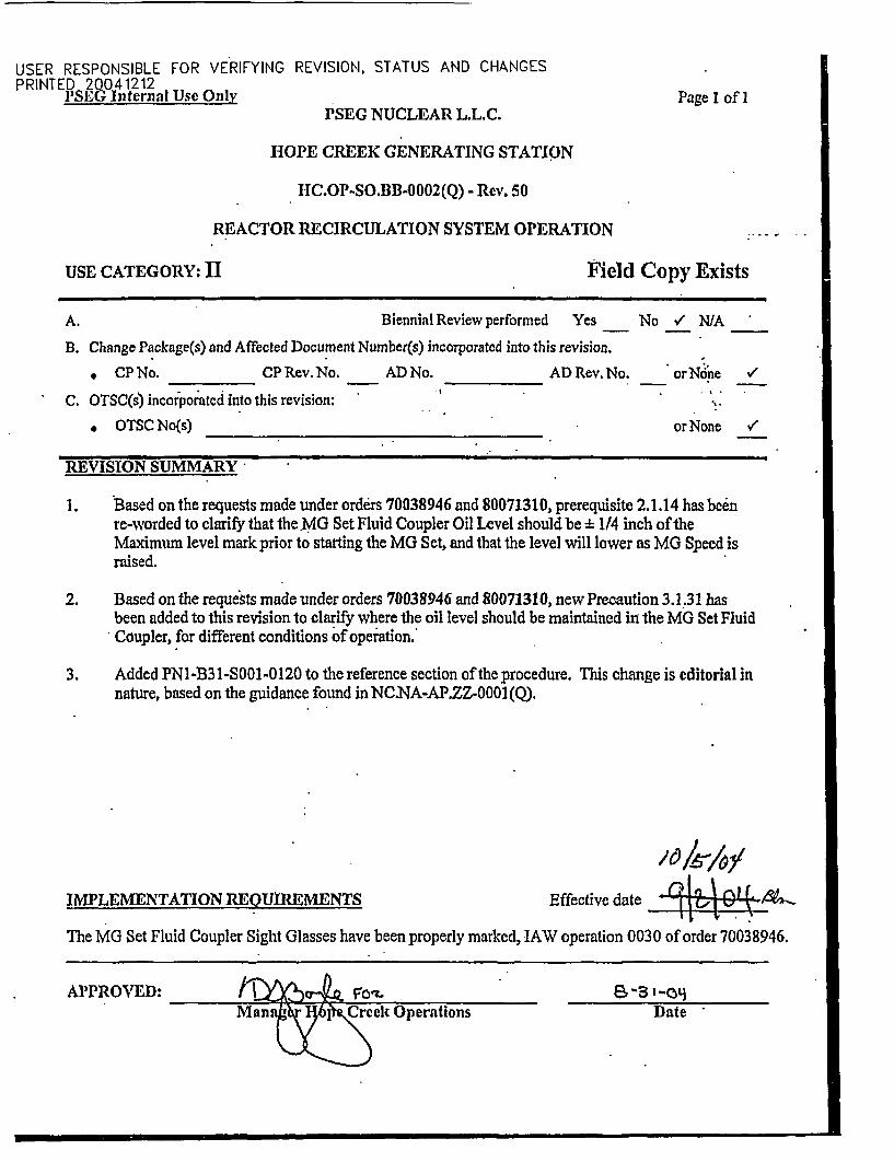
REACTOR RECIRCULATION SYSTEM OPERATI ON
TABLE OF CONTENTS
Section Title
1.0 PURPOSE.
2.0 PREREQUISITES....................................................................................................
3.0 PRECAUTIONS AND LIMITATIONS.
4.0 EQUIPMENT REQUIRED.....................................................................................
5.0 PROCEDURE ........................
5.1 Reactor Recirculation System Startup.
5.2 Reactor Recirculation System Two Loop Operation .
5.3 Reactor Recirculation System Single Loop Operation.
5.4 Resetting Reactor Recirculation Pump Runback.
5.5 Scoop Tube Positioner Lockup Operation .
5.6 Reactor Recirculation System Shutdown.
5.7 Reactor Recirculation Pump Quick Restart.
5.8 Oil Mist Eliminator Operation .
6.0 RECORDS...........................................................................................................................
7.0 REFERENCES .........
ATTACHMENTS
Attachment I Power to Flow Map..................................................................................
XI1BIT
Exhibit I Reactor Recirculation Pump Motor..........................................................
Pagc
2
2
6
15
16
17
33
38
44
45
49
53
61
62
62
64
66.
Hope Creek Page 1 of 66 Rev. 50
USER RESPONSIBLE FOR VERIFYING REVISION, STATUS AND CHANGESPRINTED 20041212
PSEG Internal Use Only IIC.OP-SOJIBI-0002(Q)
REACTOR RECIRCULATION SYSTEM OPERATION
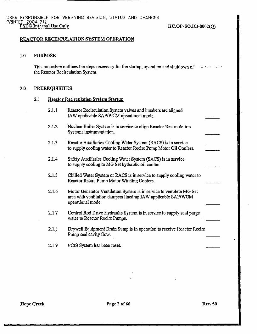
1.0 PURPOSE
This procedure outlines the steps necessary for the startup, operation and shutdown ofthe Reactor Recirculation System.
2.0 PREREQUISITES
2.1 Reactor Recirculation System Startup
2.1.1 Reactor Recirculation System valves and breakers are alignedIAW applicable SAP/WCM operational mode.
2.1.2 Nuclear Boiler System is in service to align Reactor RecirculationSystems instrumentation.
2.1.3 Reactor Auxiliaries Cooling Water System (RACS) is in serviceto supply cooling water to Reactor Recirc Pump Motor Oil Coolers.
2.1.4 Safety Auxiliaries Cooling Water System (SACS) is in serviceto supply cooling to MG Set hydraulic oil cooler.
2.1.5 Chilled Water System or RACS is in service to supply cooling water toReactor Recirc Pump Motor Winding Coolers.
2.1.6 Motor Generator Ventilation System is in serviceto ventilate MG Setarea with ventilation dampers lined up JAW applicable SAP/WCMoperational mode.
2.1.7 Control Rod Drive Hydraulic System is in service to supply seal purgewater to Reactor Recirc Pumps.
2.1.8 Drywell Equipment Drain Sump is in operation to receive Reactor RecircPump seal cavity flow.
2.1.9 PCIS System has been reset.
Hope Creek Page 2 of 66 Rev. 50
USER RESPONSIBLE FOR VERIFYING REVISION, STATUS AND CHANGESPRINTED 20041212
PSEG Internnl Use Only HC.OP-SO.13B-0002(Q)
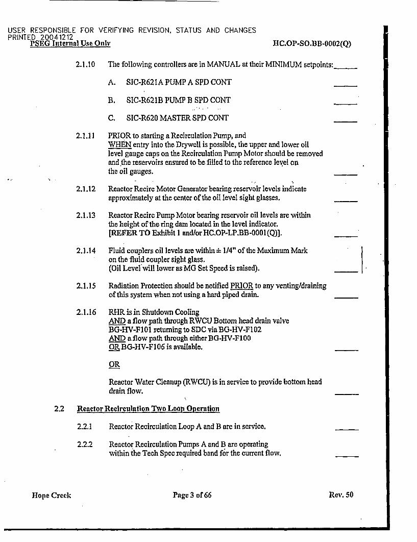
2.1.10 The following controllers are in MANUAL at their MINIMUM setpoints:_
A. SIC-R621A PUMP A SPD CONT
B. SIC-R621B PUMP B SPD CONT
C. SIC-R620 MASTER SPD CONT
21.11 PRIOR to starting a Recirculation Pump, andWHEN entry into the Drywell is possible, the upper and lower oillevel gauge caps on the Recirculation Pump Motor should be removedand the reservoirs ensured to be filled to the reference level onthe oil gauges.
2.1.12 Reactor Recirc Motor Generator bearing reservoir levels indicateapproximately at the center of the oil level sight glasses.
2.1.13 Reactor Recire Pump Motor bearing reservoir oil levels are withinthe height of the ring dam located in the level indicator.[REFER TO Exhibit I and/orHC.OP-LP.BB-0001(Q)].
2.1.14 Fluid couplers oil levels are within d 114" of the Maximum Markon the fluid coupler sight glass.(Oil Level will lower as MG Set Speed is raised). .
2.1.15 Radiation Protection should be notified PRIOR to any venting/drainingof this system when not using a hard piped drain.
2.1.16 RHIR is in Shutdown CoolingAND a flow path through RWCU Bottom head drain valveBG-H V-F01 returning to SDC via BG-H V-F102AND a flow path through either BG-HV-F100OR BO-HV-Fl 06 is available.
OR
Reactor Water Cleanup (RWCU) is in service to provide bottom headdrain flow.
2,2 Reactor Recirculation Two Loop Operation
2.2.1 Reactor Recirculation Loop A and B are in service.
2.2.2 Reactor Recirculation Pumps A and B are operatingwithin the Tech Spec required band f6r the current flow.
Hope Creek Page 3 of 66 Rev. 50
USER RESPONSIBLE FOR VERIFYING REVISION, STATUS AND CHANGESPRINTED 20041212
PSE G Internal Use Only NC.OP-SO.BB-0002(Q)
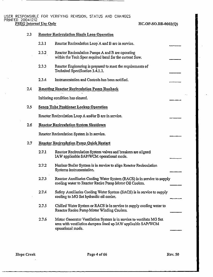
2.3 Reactor Recirculation Single Loop Operation
2.3.1 Reactor Recirculation Loop'A and B are in service.
2.3.2 Reactor Recirculation Pumps A and B are operatingwithin the Tech Spec required band for the current flow.
2.3.3 Reactor Engineering is prepared to meet the requirements ofTechnical Specification 3.4.1.1.
2.3.4 Instrumentation and Controls has been notified.
2.4 Resetting Reactor Recirculation Pump Runback
Initiating condition has cleared.
2.5 Scoop Tube Positioner Lockup Operation
Reactor Recirculation Loop A and/or B are in service.
2.6 Reactor Recirculation System Shutdown
Reactor Recirculation System is in service.
2.7 Reactor Recirculation Pump Quick Restart
2.7.1 Reactor Recirculation System valves and breakers are alignedIAW applicable SAP/WCM operational mode.
2.7.2 Nuclear Boiler System is in service to align Reactor RecirculationSystems instrumentation.
2.7.3 Reactor Auxiliaries Cooling Water System (RACS) is in service to supplycooling water to Reactor Recirc Pump Motor Oil Coolers.
2.7.4 Safety Auxiliaries Cooling Water System (SACS) is in service to supplycooling to MG Set hydraulic oil cooler.
2.7.5 Chilled Water System or RACS is in service to supply cooling water toReactor Recirc Pump Motor Winding Coolers.
2.7.6 Motor Generator Ventilation System is in service to ventilate MG Setarea with ventilation dampers lined up IAW applicable SAPIWCMoperational mode.
H1ope Creek Page 4 of 66 Rev. 50
USER RESPONSIBLE FOR VERIFYING REVISION, STATUS AND CHANGESPRINTED 20041212
PSEG Internal Use Only HC.OP-SO.BB-0002(Q)
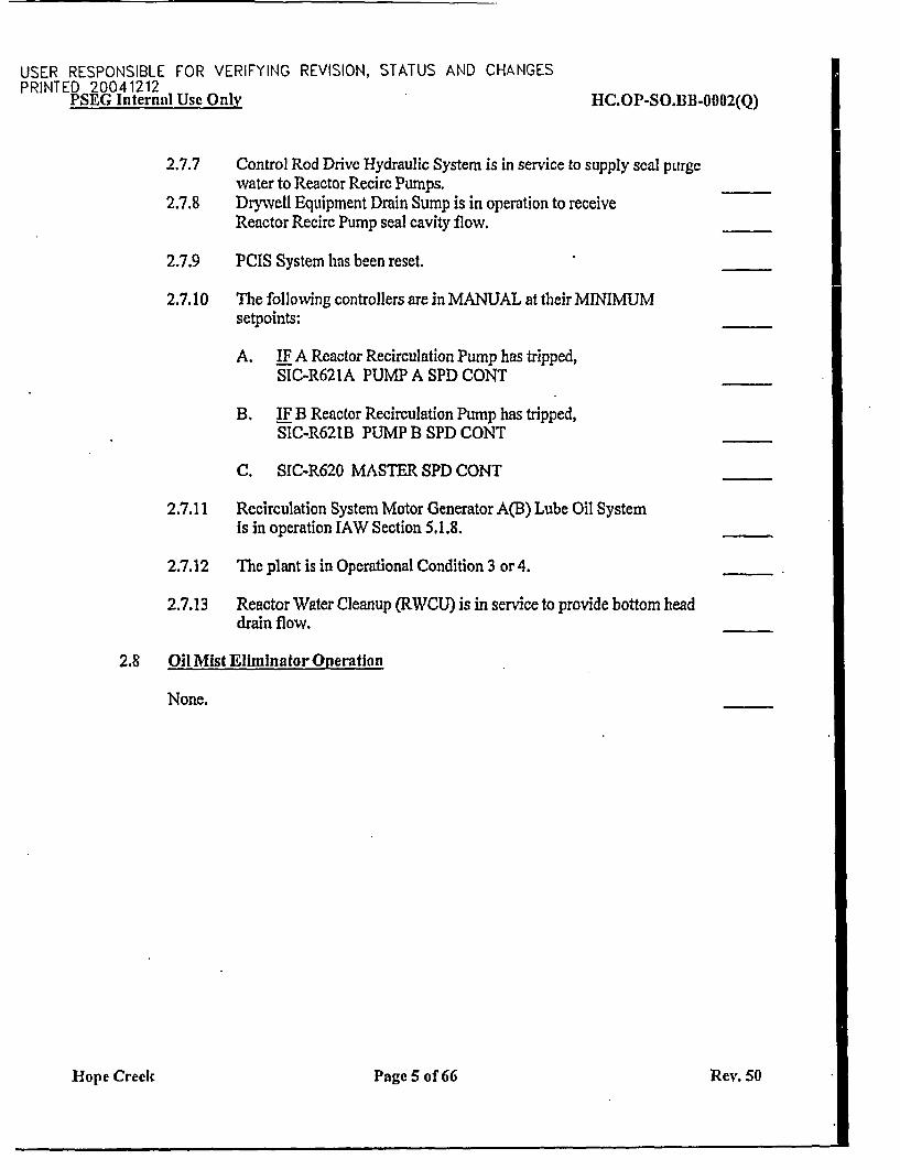
2.7.7 Control Rod Drive Hydraulic System is in service to supply seal purgewater to Reactor Recirc Pumps.
2.7.8 Drywell Equipment Drain Sump is in operation to receiveReactor Recirc Pump seal cavity flow.
2.7.9 PCIS System has been reset.
2.7.10 The following controllers are in MANUAL at their MINIMUMsetpoints:
A. IF A Reactor Recirculation Pump has tripped,SIC-R621A PUMP A SPD CONT
B. IF B Reactor Recirculation Pump has tripped,SIC-R621B PUMP 13 SPD CONT
C. SIC-R620 MASTER SPD CONT
2.7.11 Recirculation System Motor Generator A(B) Lube Oil Systemis in operation IAW Section 5.1.8.
2.7.12 The plant is in Operational Condition 3 or 4.
2.7.13 Reactor Water Cleanup (RWCU) is in service to provide bottom headdrain flow.
2.8 Oil Mist Eliminator Operation
None.
Hope Creek Page 5 of 66 Rev. 50
USER RESPONSIBLE FOR VERIFYING REVISION, STATUS AND CHANGESPRINTED 20041212
PSEG Internal Use Only HC.OP-SO.B1B-0002(Q)
3.0 PRECAUTIONS AND LIMITATIONS
3.1 Precautions
3.1.1 Limitations of Technical Specification 3.4.1.1 prior to Shutdown of anoperating Recirculation Loop during Operational Conditions 1 AND 2 shallbe observed. Reactor Engineering AND Instrumentation and Controls mustbe notified.
3.1.2 To avoid over-pressurizing the pump casing, the Seal Purge Water for theReactor Recirc Pump Seals shall be secured PRIOR to isolating a Reactor,Recirc Pump. [CD-781A, CD455H]
3.1.3 Closure of both Reactor Recire Pump Suction Valves simultaneouslywill result in a loss of Reactor Water Cleanup System suction.
3.1.4 The Limitations of Technical Specification 3.4.1.4 shall be observedPRIOR to starting an idle Recirculation Pump.
3.1.5 BB-HV-FO31A(B) PUMP A(B) DISCH VALVE should be closed for> 5 minutes only for shutdown cooling or pump maintenance. [CD-976B]
3.1.6 WHEN locally adjusting Scoop Tube position, the licensed operator performingthe adjustment must remain in constant communication with the NCO in theMain Control Room while locally adjusting Scoop Tube positionWITH the Reactor Recirc Pump in operation.
3.1.7 The Scoop Tube Positioner should NOT be manually positioned unless theScoop Tube Positioner power switch is OFF.
3.1.8 When coming out of Scoop Tube Lockup, the potential exists for theRecirc Pump to "Run Away", and the Operator should be prepared totake appropriate action.
Hope Creek Page 6 of 66 Rev. 50
USER RESPONSIBLE FOR VERIFYING REVISION, STATUS AND CHANGESPRINTED ?.0041212YNE 1lG Internal Use Only HC.OP-SO.TJB-0002(Q)
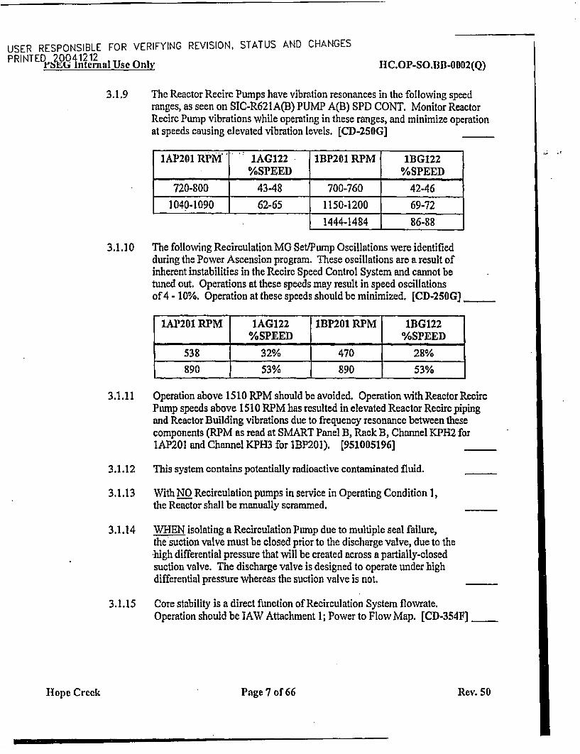
3.1.9 The Reactor Recirc Pumps have vibration resonances in the following speedranges, as seen on SIC-R621A(B) PUMP A(B) SPD CONT. Monitor ReactorRecirc Pump vibrations while operating in these ranges, and minimize operationat speeds causing elevated vibration levels. [CD-250G]
IAP201 RPMM IAG122 IBP201 RPM 1BG122%SPEED %SPEED
720-800 4348 700-760 42-46
1040-1090 62-65 1150-1200 69-72
1444-1484 86-88
3.1.10 The following Recirculation MG Set/Pump Oscillations were identifiedduring the Power Ascension program. These oscillations are a result ofinherent instabilities in the Recirc Speed Control System and cannot betuned out. Operations at these speeds may result in speed oscillationsof 4 - 10%. Operation at these speeds should be minimized. [CD-250G] _ _
IAP2Q1 RPM 1AG122 IBP201 RPM lBG122%SPEED %SPEED
538 32% 470 28%
890 53% 890 53% 1
3.1.11 Operation above 1510 RPM should be avoided. Operation withReactorRecircPump speeds above 1510 RPM has resulted in elevated Reactor Recirc pipingand Reactor Building vibrations due to frequency resonance between thesecomponents (RPM as read at SMART Panel B, Rack B, Channel KPH2 for1AP201 and Channel KPH3 for IBP201). [951005196]
3.1.12 This system contains potentially radioactive contaminated fluid.
3.1.13 With NO Recirculation pumps in service in Operating Condition 1,the Reactor shall be manually scrammed.
3.1.14 WHEN isolating a Recirculation Pump due to multiple seal failure,the suction valve must be closed prior to the discharge valve, due to the*high differential pressure that will be created across a partially-closedsuction valve. The discharge valve is designed to operate under highdifferential pressure whereas the suction valve is not.
3.1.15 Core stability is a direct function of Recirculation System flowrate.Operation should be 1AW Attachment 1; Power to Flow Map. [CD-354F]
Hope Creek Page 7 of 66 Rev. 50
USER RESPONSIBLE FOR VERIFYING REVISION. STATUS AND CHANGESPRINTED 20041212
PSEG Internal Use Only IIC.OP-SO.BB-0002(Q)
3.1.16 The 1AlP120 and 113 P120,OR the IA2P120 and 1B2P120 MG Set Lube Oil Pumps shouldNOT be run together as they have power supplies on the same480V Bus (10B140 or IOB130).IF run together, a single 480V Bus trip may result in bothRecirc Pumps tripping.
3.1.17 IF a pump reaches the electrical stop, the scoop tube drive will stop andthe disc brake will engage.IF an increase demand for speed is still present, the speed demand indicatorwill slowly go to full scale and a scoop tube lockup will occur. The ScoopTube Reset Push button must be pressed to disengage the brake.
3.1.18 IF RPT Brkr A,(B,C,D)N205 for a Recirc Pump trips, the Drive Motorbreaker will not trip (DCP 4HE-0222). The Recirc MG Set shouldbe secured IAW HC.OP-SO.BB-0002(Q).
3.1.19 A loss of Recirc. MG Set Ventilation will not result in an automatictrip of the MG Set Drive Motor breakers.
3.1.20 WHEN the RHR System is operating in the Shutdown Cooling Mode,Recirc Loop suction and discharge valve manipulations that result in aShutdown Cooling Loop bypass flowpath being established shall be avoided(example: recirc suction and discharge valves being open simultaneouslyon the loop seeing Shutdown Cooling return flow)
3.1.21 Following Recirculation Pump seal maintenance, seal vents should remainopen until seal purge is established and seals are flushed and vented. Thisprevents small particles from entering the pump cavity and seals due toflooding without seal purge established. [CDA4551
3.1.22 The Reactor Recirc Pump Seal cavities must be thoroughly vented priorto pump operation to reduce seal wear. [CD-781A]
3.1.23 BB-HV-F023A(B) PUMP A(B) SUCT VALVE should only be closed forpump maintenance or leak isolation.
3.1.24 PRIOR to commencing Single Recirculation Loop Operations, ReactorEngineering and Instrumentation and Controls must be notified.
3.1.25 IF a Recirc MG Set fails to start, the Recirc Pump discharge Valve (F03 1)may not be fully closed. Shutdown cooling could be compromisedIF the valve is left partially open. [PR 960105118]
Hope Creek Page 8 of 66 Rev. 50
USER RESPONSIBLE FOR VERIFYING REVISION, STATUS AND CHANGESPRINTED 20041212P rSit0t; Internal Use Only HC.O'-SO.BB-0002(Q)
3.1.26 With the operable loop drive flow near 23 Kgpm (approximately 48%Pump speed), the flow through the idle loop is close to zero and willswap back and forth between forward and reverse flow. Operation cancause excessive jet pump vibration and the potential for consequentstress fatigue of the riser brace welds to the vessel.Operation in this area should be minimized. [800332701
3.1.27 1-BF-V155(772) and I-BF-l 56(773) Recirc Pmps Seal Purge SupplyHdr Vent Vlvs should remain open any time the downstream isolationvalves are closed. 170029861]
3.1.28 Approximately 45 minutes may be required to stabilize motor-generatorlube oil temperatures during post-maintenance equipment starts.Control Room temperature recorders B3 1-TRR625 and CRIDS pointsA2911 and A2912 provide pertinent parameter information and should bemonitored for this duration. Local observation should also be in place.[700315151
3.1.29 PRIOR to placing OIL MIST ELIMINATOR 1A-V-136 in service ensureproper oil collection apparatus is attached to collect oil.
3.1.30 Due to concerns with Oil Vapors being released to the atmosphereof the M-G room, the "A" Reactor Recirc Pump M-G Oil MistEliminator (HIBEB -1A-V-136) should only be placed in-servicewhen the "A" Reactor Recirculation Pump is being maintained ata steady speed ("Stable Power Operation"), and should not be usedwhile "Maneuvering Power". Minor adjustments in Reactor RecircPump Speed, to maintain "Stable Power Operation", should beconsidered as "Stable Power Operation".[70036590]
3.1.31 With the MG Set out of service, the Fluid Coupler Oil Level should beat the Maximum level mark, h 1/4 inch. While operating, the FluidCoupler Oil Level should be maintained between the Maximum andMinimum levels per the gauge glass. The oil level will raise as pumpspeed is lowered. When adding Oil at 100% power, only add oil to theMinimum level mark + 1/2 inch, - zero inch.
Hop~e Creek Page 9 of 66 Rev. so
USER RESPONSIBLE FOR VERIFYING REVISION, STATUS AND CHANGESPRINTED 20041212
PSEG Internal Use Only HC.OP-SO.1IB-0002(Q)
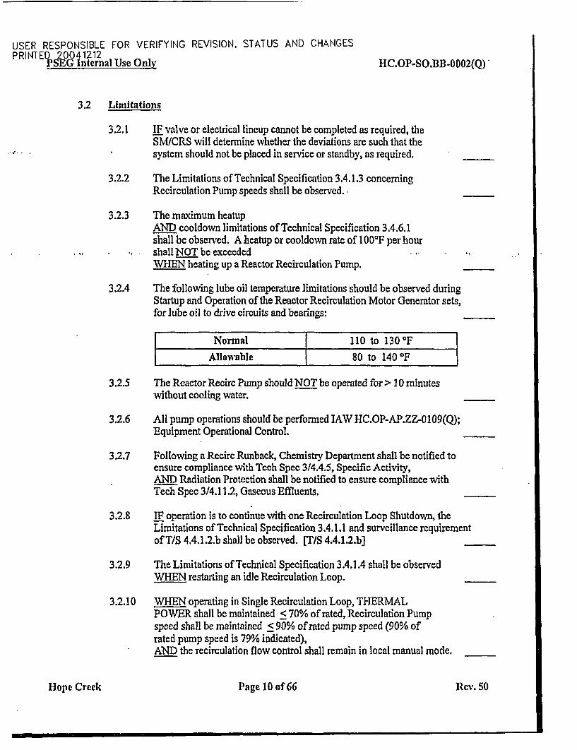
3.2 Limitations
3.2.1 IF valve or electrical lineup cannot be completed as required, theSM/CRS will determine whether the deviations are such that thesystem should not be placed in service or standby, as required.
3.2.2 The Limitations of Technical Specification 3.4.1.3 concerningRecirculation Pump speeds shall be observed. _
3.2.3 The maximum heatupAND cooldown limitations of Technical Specification 3.4.6.1shall be observed. A heatup or cooldown rate of 1 000F per hourshall NOT be exceeded .
WIEN heating up a Reactor Recirculation Pump.
3.2.4 The following lube oil temperature limitations should be observed duringStartup and Operation of the Reactor Recirculation Motor Generator sets,for lube oil to drive circuits and bearings:
Nonnal 1 10 to 130'FAllowable 80 to 140 IF
3.2.5 The Reactor Recirc Pump should NOT be operated for > 10 minuteswithout cooling water.
3.2.6 All pump operations should be performed IAW HC.OP-AP.ZZ-0109(Q);Equipment Operational Control.
3.2.7 Following a Recirc Runback, Chemistry Department shall be notified toensure compliance with Tech Spec 3/4.4.5, Specific Activity,AND Radiation Protection shall be notified to ensure compliance withTech Spec 3/4.11.2, Gaseous Effluents.
3.2.8 IF operation is to continue with one Recirculation Loop Shutdown, theLimitations of Technical Specification 3.4.1.1 and surveillance requirementof T/S 4.4.1.2.b shall be observed. [TIS 4.4.1.2.bJ
3.2.9 The Limitations of Technical Specification 3.4.1.4 shall be observedWHEN restarting an idle Recirculation Loop.
3.2.10 WHEN operating in Single Recirculation Loop, THERMALPOWER shall be maintained < 70% of rated, Recirculation Pumpspeed shall be maintained < 90% of rated pump speed (90% ofrated pump speed is 79% indicated),AND the recirculation flow control shall remain in local manual mode.
Hope Creek Page 10 of 66 Rev. 50
ON THE SPOT CHANGEPRINTED 20041212
IT IS THE RESPONSIBILITY OF THE USER TO VERIFY REVISION, STATUSPRINTED 2QQ4.1Q2l Use Only FIC.OP-SO.BB-0002(Q)
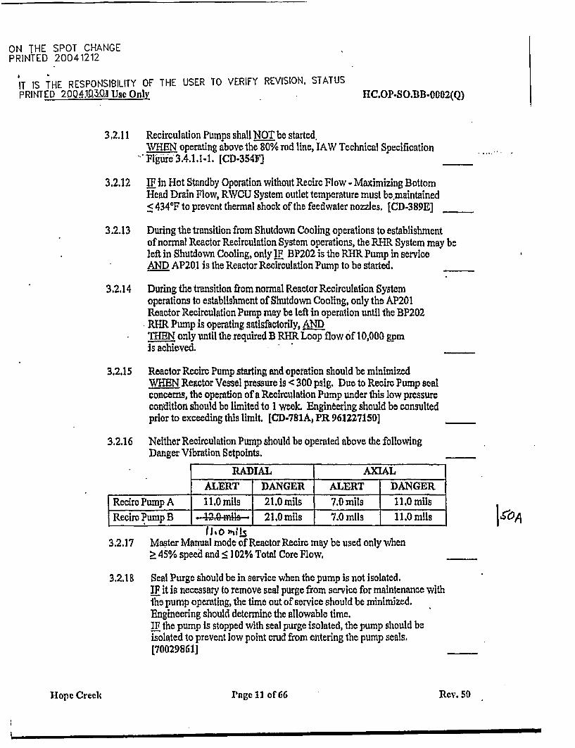
3.2.11 Recirculation Pumps shall NOT be started.WHIEN operating above the 80% rod line, lAW Technical SpecificationPlgiue 3.4.1.1-1. [CD-354F]
3.2.12 IF in Hot Standby Operation without Recirc Flow - Maximizing BottomHead Drain Flow, RWCU System outlet temperature must be.maintained< 4340 F to prevent thermal shock of the feedwater nozzles. [CD-389E]
3.2.13 During the transition from Shutdown Cooling operations to establishmentof normal Reactor Recirculation System operations, the RHR System may beleft in Shutdown Cooling, only LF BP202 is the RHR Pump in serviceAND AP201 is the Reactor Recirculatlon Pump to be started.
3.2.14 During the transition from normal Reactor Recirculation Systemoperations to establishment of Shutdown Cooling, only the AP201Reactor Recirculation Pump may be left in operation until the BP202RHR Pump is operating satisfactorily, ANIDTHEN only until the required B RHR Loop flow of 10,000 gpmis achieved.
3.2.15 Reactor Recirc Pump starting and operation should be minimizedWHEN Reactor Vessel pressure is < 300 pslg. Due to Recirc Pump sealconcerns, the operation of a Recirculation Pump under this low pressurecondition should be limited to I week. Engineering should be consultedprior to exceeding this limit, [CD-781A, PR 96122715D]
3.2.16 Neither Recirculation Pump should be operated above the followingDanger Vibration Setpoints.
RADIAL AXIALALERT I DANGER ALERT I DANGER
Reciro Pump A 11.0 mils 21.0 mils 7.0 milsII.0 milRecirc Pump B 2 1. 0 7.0 m| 7.0milsJ 1.0 mlls
. I - -Ito 0 als
3.2.17 Master Manual mode of Reactor Recire may be used only when> 45% speed and c 102% Total Core Flow,
3.2.1 8 Seal Purge Should be in service when the pump is not isolated.IF It is necessary to remove seal purge from service for maintenance withthe pump operating, the time out of service should be minimized.Engineering should determine the allowable time.IF the pump is stopped with seal purge isolated, the pump should beisolated to prevent low point crud from entering the pump seals.[700298611
Hope Creek Page 11 of 66 Rey. so
I
USER RESPONSIBLE FOR VERIFYING REVISION, STATUS AND CHANGESPRINTED 20041212rM!At, internatl Use Only HC.OP-SO.BB-0002(Q)
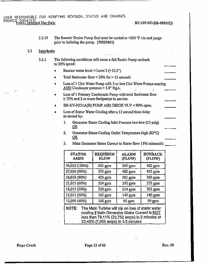
3.2.19 The Reactor Recirc Pump Seal must be cooled to <200 IF via seal purgeprior to isolating the pump. [700298611
3.3 Interlocks
3.3.1 The following conditions will cause a full Recirc Pump runbackto 30% speed:
* Reactor water level <Level 3 (+12.5")
* Total feedwater flow < 20% for > 15 seconds
* Loss of I Circ Water Pump with 3 or less Circ Water Pumps runningAND Condenser pressure > 5.8" 1-gA. !
* Loss of I Primary Condensate Pump with total feedwater flow> 75% and 2 or more feedpumps in service.
* BB-HV-F031A(B) PUMP A(B) DISCH VLV < 90% open.
* Loss of Stator Water Cooling after a 12 second time delayas sensed by:
1. Generator Stator Cooling Inlet Pressure low-low (13 psig)OR
2. Generator Stator Cooling Outlet Temperature high (820C)OR
3. Main Generator Stator Current to Stator flow 15% mismatch:
STATOR REQUIRED ALARM RUNBACKAMPS FLOW (FLOW) (FLOW)
30,022 (100%) 661 gpm 595 gpm 562 gpm
27,020 (90%) 535 gpm 482 gpm 455 gpm
24,018 (80%) . 423 gpm 381 gpm 360 gpm
21,015 (60%) 324 gpm 292 gpm 275 gpm
18,013 (50%) 238 gpm 214 gpm 202 gpm
15,011 (50%) 165 gpm 149 gpm 140 gpm
12,009 (40%) 106 gpm 95 gpm 90 gpm
NOTE: The Main Turbine will trip on loss of stator watercooling if Main Generator Stator Current is NOTless than 79.11% (23,752 amps) in 2 minutes or23.49% (7,055 amps) In 3.5 minutes
Hope Crecek Page 12 of 66 Rev. 50
USER RESPONSIBLE FOR VERIFYING REVISION, STATUS AND CHANGESPRINTED 20041212rbt±U1 internal Use Only HC.OP-SO.BB-0002(Q)
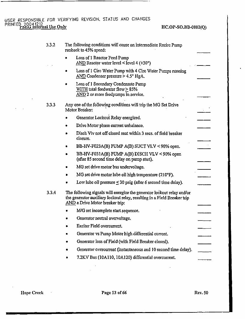
3.3.2 The following conditions will cause an intermediate Recirc Pumprunback to 45% speed:
Loss of I Reactor Feed PumpAND Reactor water level < level 4 (+30")
* Loss of I Circ Water Pump with 4 Circ Water Pumps runningAND Condenser pressure > 4.5" HgA.
* Loss of I Secondary Condensate PumpWITH total feedwater flow> 85%AND 2 or more feedpumps in service.
3.3.3 Any one of the following conditions will trip the MG Set DriveMotor Breaker:
* Generator Lockout Relay energized.
* Drive Motor phase current unbalance.
* Disch Vlv not off closed seat within 3 secs. of field breakerclosure.
* BB-HV-F023A(B) PUMP A(B) SUCT VLV < 90% open.
* BB-HV-FO3lA(B) PUMP A(B) DISCH VLV < 90% open(after 85 second time delay on pump start).
* MG set drive motor bus undervoltage.
* MG set drive motor lube oil high temperature (21 00F).
c Low lube oil pressure < 30 psig (after 6 second time delay).
3.3.4 The following signals will energize the generator lockout relay and/orthe generator auxiliary lockout relay, resulting in a Field Breaker tripAND a Drive Motor breaker trip:
* M/G set incomplete start sequence.
Generator neutral overvoltage.
* Exciter Field overcurrent.
Generator vs Pump Motor high differential current.
* Generator loss of Field (with Field Breaker closed).
Generator overcurrent (instantaneous and I 0 second time delay),
* 7.2KV Bus (lOAl10, 10A120) differential overcurrent.
H~ope Creek Page 13 of 66 Rev. 50
USER RESPONSIBLE FOR VERIFYING REVISION, STATUS AND CHANGESPRINTED 20 041212
P I tt, internal Use Only HC.OP-SO.IIB-0002(Q)
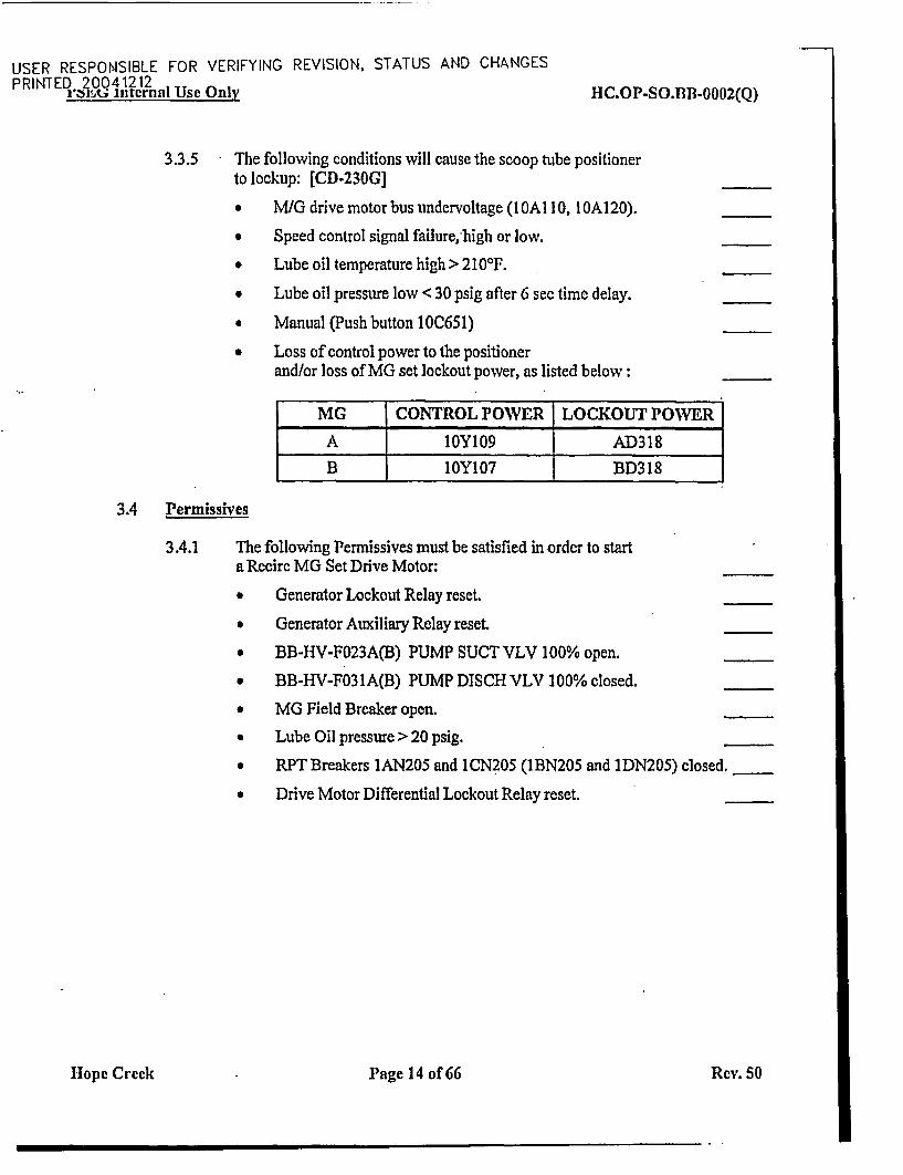
3.3.5 The following conditions will cause the scoop tube positionerto lockup: [CD-230G]
* M/G drive motor bus undervoltage (I OA] 10, O.A120).
* Speed control signal failure, high or low.
* Lube oil temperature high > 210F.
Lube oil pressure low < 30 psig after 6 sec time delay.
a Manual (Push button 10C651)
* Loss of control power to the positionerand/or loss of MG set lockout power, as listed below:
MG CONTROL POWER LOCKOUT POWE R
A lOY109 AD31 8
B 10Y107 BD318
3.4 Permissives
3.4.1 The following Pernissives must be satisfied in order to starta Recirc MG Set Drive Motor:
* Generator Lockout Relay reset.
* Generator Auxiliary Relay reset
* BB-HV-P023A(B) PUMP SUCT VLV 100% open.
* BB-HV-F031A(B) PUMP DISCH VLV 100% closed.
MG Field Breaker open.
Lube Oil pressure > 20 psig.
RPT Breakers 1AN205 and ICN205 (lBN205 and 1DN205) closed.
* Drive Motor Differential Lockout Relay reset.
Hope Creek Page 14 of 66 Rev. 50
USER RESPONSIBLE FOR VERIFYING REVISION, STATUS AND CHANGESPRINTED 20012
rPRNE internal Use Only RC.OP-SO.BB-0002(Q)
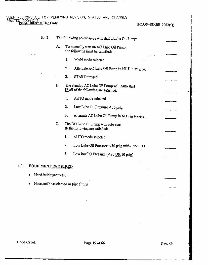
3.4.2 The following permissives will start a Lube Oil Pump:
A. To manually start an AC Lube Oil Pump,the following must be satisfied:
1. MAN mode selected
2. Alternate AC Lube Oil Pump in NOT in service.
3. START pressed
B. The standby AC Lube Oil Pump will Auto startIF all of the following are satisfied:
1. AUTO mode selected
2. Low Lube Oil Pressure < 30 psig
3. Alternate AC Lube Oil Pump in NOT in service.
C. The DC Lube Oil Pump will auto startIF the following are satisfied:
1. AUTO mode selected
2. Low Lube Oil Pressure < 30 psig with 6 sec. TD
3. Low low LO Pressure (< 20 OR 10 psig)
4.0 EQUIPMENT REQUIRED
* Hand-held pyrometer
* Hose and hose clamps or pipe fitting
Hope Creek Page 15 of 66 Rev. 50
-
USER RESPONSIBLE FOR VERIFYING REVISION, STATUS AND CHANGESPRINTED ?OQ4121 2
I'MEG Internal Use Only HC.OP-SO.BB-0002(Q)
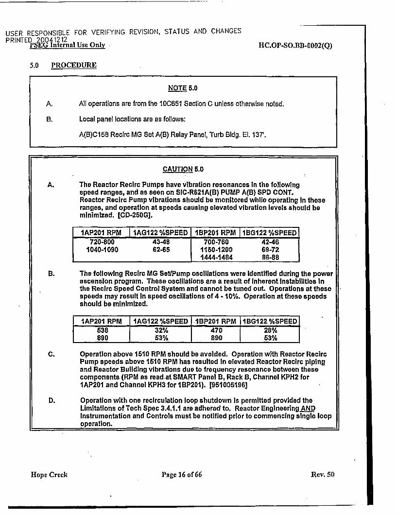
5.0 PROCEDURE
NOTE 6.0
A. All operations are from the 10C651 Section C unless otherwise noted.
B. Local panel locations are as follows:
A(B)C158 Recirc MG Set A(B) Relay Panel, Turb Bldg. El. 137'.
CAUTION 6.0
A. The Reactor Recirc Pumps have vibration resonances in the followingspeed ranges, and as seen on SIC.R621A(B) PUMP A(B) SPD CONT.Reactor Recirc Pump vibrations should be monitored while operating In theseranges, and operation at speeds causing elevated vibration levels should beminimized. [CD-250G].
IAP201 RPM -1AG122 %SPEED 1BP201 RPMI 1IBG122 %SPEED720-800 4348 - 700-760 42-46
1040-1090 62-65 1150-1200 69-721444-1484 86-88
B. The following Recirc MG Set/Pump oscillations were identified during the powerascension program. These oscillations are a result of Inherent Instabilities Inthe Recirc Speed Control System and cannot be tuned out. Operations at thesespeeds may result In speed oscillations of 4 - 10%. Operation at these speedsshould be minimized.
IAP201 RPM 1AG122 %SPEED IBP201 RPM 1BG122 %SPEED638 32% 470 28%890 63% 1 890 63%
C. Operation above 1510 RPM should be avoided. Operation with Reactor RecircPump speeds above 1510 RPM has resulted In elevated Reactor Recirc pipingand Reactor Building vibrations due to frequency resonance between thesecomponents (RPM as read-at SMART Panel B, Rack B, Channel KPH2 forIAP201 and Channel KPH3 for IBP201). [951005196]
D. Operation with one recirculation loop shutdown Is permitted provided theLimitations of Tech Spec 3.4.1.1 are adhered to. Reactor EngineeringANDInstrumentation and Controls must be notified prior to commencing single loopoperation.
Hope Creek Page 16 of 66 ]tev. 50
USER RESPONSIBLE FOR VERIFYING REVISION, STATUS AND CHANGESPRINTED 20Q41212rV internal Use Only HC.OP-SO.BB-0002(Q)
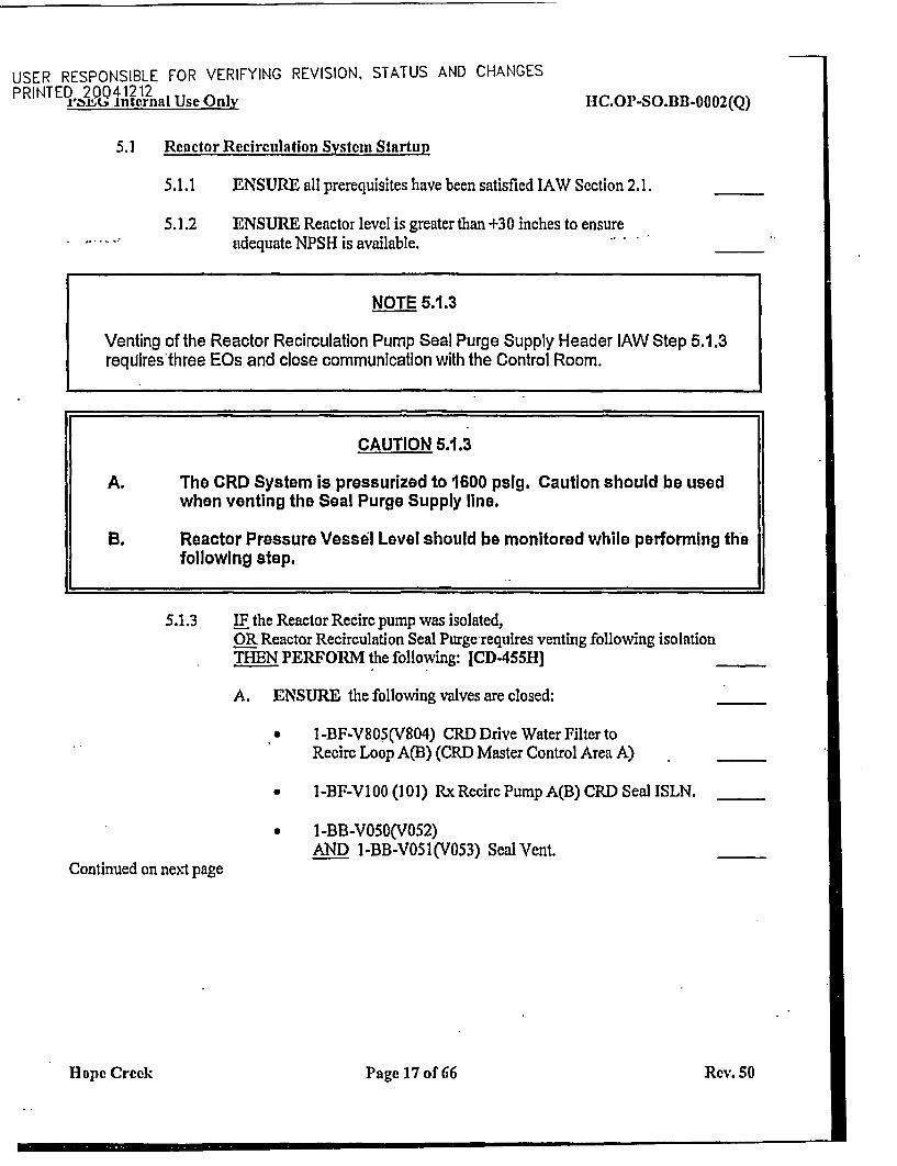
5.1 Reactor Recirculation System Startup
5.1.1
5.1.2
ENSURE all prerequisites have been satisfied IAW Scction 2.1.
ENSURE Reactor level is greater than +30 inches to ensureadequate NPSH is available.
NOTE 5.1.3
Venting of the Reactor Recirculation Pump Seal Purge Supply Header lAW Step 5.1.3requires three EOs and close communication with the Control Room.
CAUTION 5.1.3
A. The CRD System is pressurized to 1600 pslg. Caution should be usedwhen venting the Seal Purge Supply line.
B. Reactor Pressure Vessel Level should be monitored while performing thefollowing step.
5.1.3 IF the Reactor Recirc pump was isolated,OR Reactor Recirculation Seal Purge-requires venting following isolationTHEN PERFORM the following: [CD455H]
A. E NSURE the following valves are closed:
* I-BF-V805(V804) CRD Drive Water Filter toRecirc Loop A(B) (CRD Master Control Area A)
v 1-BF-VIOO (101) RxRecirc Pump A(B) CRD Seal ISLN.
* 1-BB-V050(V052)AND 1-BB-V051(V053) Seal Vent.
Continued on next page
Hope Creek Page 17 of 66 Rev. 50
USER RESPONSIBLE FOR VERIFYING REVISION, STATUS AND CHANGESP RI NT ED 6200 41212
r iU Internal Use Only IIC.OP-SO.BB-0002(Q)
5.1.3 (Continued)
NOTE 5.1.3.B
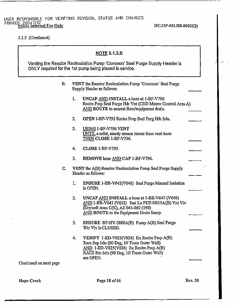
Venting the Reactor Recirculation Pump 'Common' Seal Purge Supply Header isONLY required for the 1st pump being placed In service.
B. VENT the Reactor Recirculation Pump 'Common' Seal PurgeSupply Header as follows:
1. UNCAP AND INSTALL a hose at 1-BF-V796Recirc Pmp Seal Purge Hdr Vnt (CRD Master Control Area A)AND ROUTE to nearest floor/equipment drain.
2. OPEN I-BF-V795 Recirc Pmp Seal Purg Hdr Isin.
3. USING 1-BF-V796 VENTUNTIL a solid, steady stream issues from vent hoseTHEN CLOSE 1-BF-V796.
4. CLOSE 1-BF-V795.
5. REMOVE hose AND CAP I-BF-V796.
C. VENT the A(B) Reactor Recirculation Pump Seal Purge SupplyHeader as follows:
1. E NSURE I-BB-V042(V046) Seal Purge Manual Isolationis OPEN.
2. UNCAP AND INSTALL a hose at 1-BB-V647 (V649)AND l-BB-V645 (V652) InstLnPDT-N015A(B)VntVlv(Drywell Area C(K), AZ 045-080 (190)AND ROUTE to the Equipment Drain Sump.
3. ENSURE BF-HV-3800A(B) Pump A(B) Seal PurgeWtr Vlv is CLOSED.
4. VERIFY I-ED-V023(V024) RxRecircPmpA(B)Racs Sup Isln (90 Deg, 10' From Outer Wall)AND I-ED-V025(V026) Rx Recirc Pmp A(B)RACS Rtn IsIn (90 Deg, 10' From Outer Wall)are OPEN.
Continued on next page
Hope Crceek H rage 18 of 66 Rev. 50
I
USER RESPONSIBLE FOR VERIFYING REVISION, STATUS AND CHANGESPRINTED 20041212r~. ,internal Use OuiW 11C.OP-SO.BB-0002(Q)
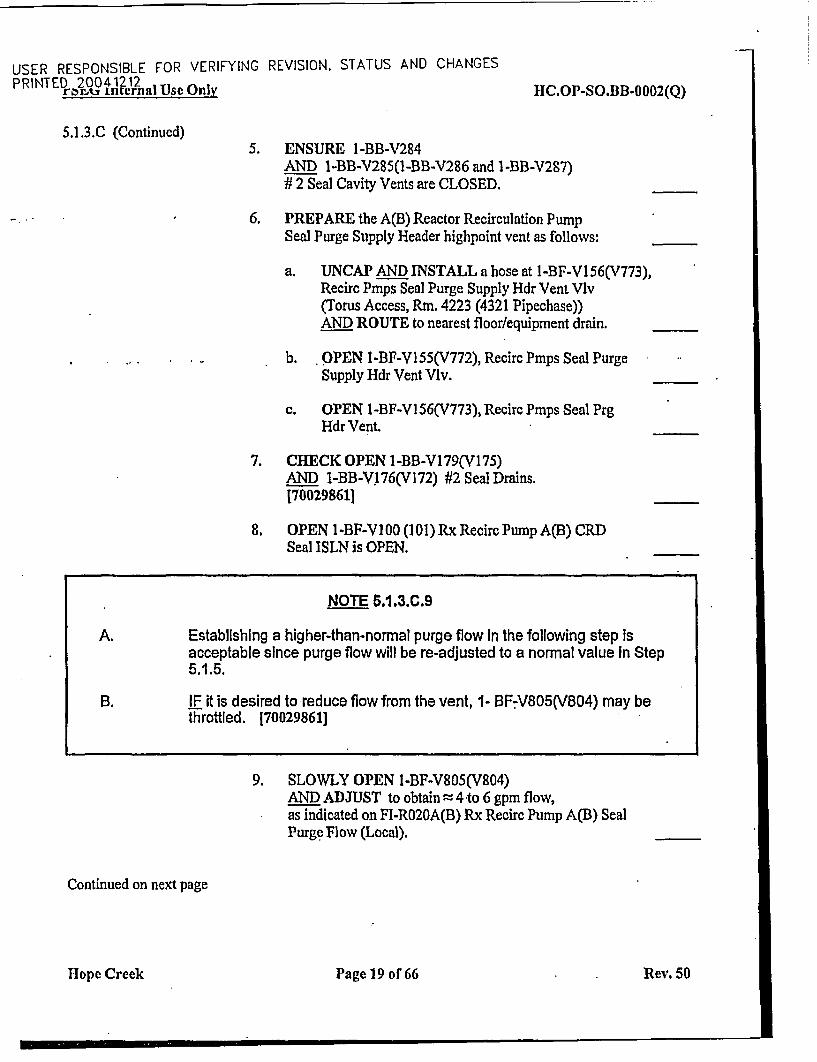
5.1.3.C (Continued)5. ENSURE I-BB-V284
AND I-BB-V285(1-BB-V286 and 1-BB-V287)# 2 Seal Cavity Vents are CLOSED.
6. PREPARE the A(B) Reactor Recirculation PumpSeal Purge Supply Header highpoint vent as follows:
a. UNCAP AND INSTALL a hose at I-BF-V156(V773),Recirc Pmps Seal Purge Supply Hdr Vent Vlv(Torus Access, Rmn. 4223 (4321 Pipechase))AND ROUTE to nearest floor/equipment drain.
b. OPEN I-BF-V155(V772), Recirc Pmps Seal PurgeSupply Hdr Vent Vlv.
c. OPEN 1-BF-V156(V773), Recirc Pmps Seal PrgHdr Vent.
7. CHECK OPEN 1-BB-V179(V175)AND I-BB-V176(V172) #2 Seal Drains.170029861]
8. OPEN 1 BF-VI00 (I01) Rx Recirc Pump A(B) CRDSeal ISLN is OPEN.
NOTE 5.1.3.C.9
A. Establishing a higher-than-normal purge flow in the following step isacceptable since purge flow will be re-adjusted to a normal value in Step5.1.5.
B. IF it is desired to reduce flow from the vent, 1- BF-V805(V804) may bethrottled. [70029861]
9. SLOWLY OPEN I-BF-V805(V804)AND ADJUST to obtain = 4 to 6 gpm flow,as indicated on Fl-RO20A(B) Rx Recirc Pump A(B) SealPurge Flow (Local).
Continued on next page
I-lopec Creek Page 19 of 66 Rev. 50
USER RESPONSIBLE FOR VERIFYING REVISION, STATUS AND CHANGESPRINTED 20041212
ySEiG Internal Use Only HIC.OP-SO.BB-0002(Q)
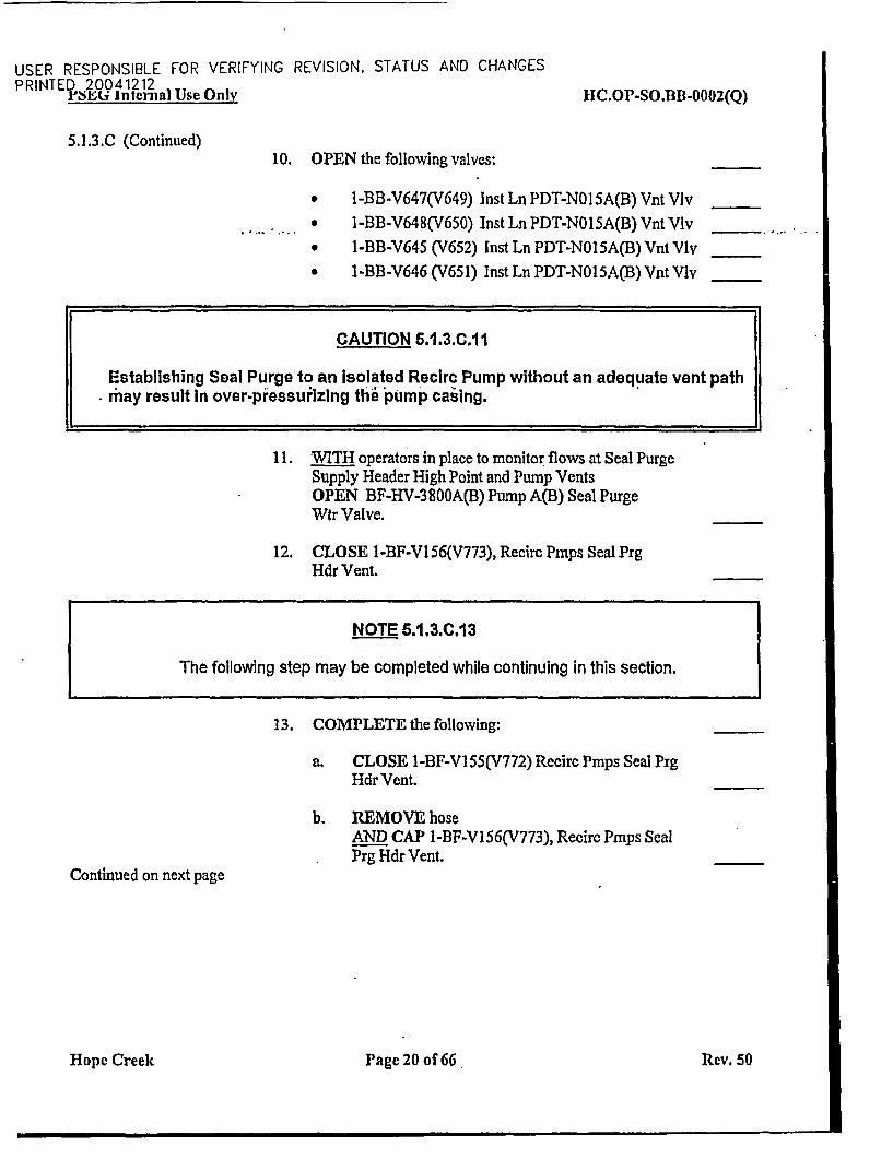
5.1.3.C (Continued)10. OPEN the following valves:
* 1-BB-V647(V649) Inst Ln PDT-NO15A(B) Vnt VIv
* I-BB-V648(V650) InstLnPDT-N015A(B)VntVlv
* I-BB-V645 (V652) Inst Ln PDT-NO15A(B) Vnt Vlv
a 1-BB-V646(V651) InstLnPDT-N015A(B)VntVlv
CAUTION 5.1.3.C.1 I
Establishing Seal Purge to an Isolated Recirc Pump without an adequate vent pathmay result In over-pressurizing the pump casing.
11. WITH operators in place to monitor flows at Seal PurgeSupply Header High Point and Pump VentsOPEN BF-HV-3800A(B) Pump A(B) Seal PurgeWtr Valve.
12. CLOSE 1-BF-V156(V773), Recirc Pmps Seal PrgHdr Vent.
NOTE 6.1.3.C.13
The following step may be completed while continuing in this section.
13. COMPLETE the following:
a. CLOSE 1-BF-V155(V772) Recirc Pmps Seal PrgHdr Vent.
b. REMOVE hoseAND CAP 1-BF-V156(V773), Recirc Pmps SealPrg Hdr Vent.
Continued on next page
Hope Creek Page 20 of 66 Rev. 50
USER RESPONSIBLE FOR VERIFYING REVISION, STATUS AND CHANGESPRINTED 20041212r i't, internal Use Only HC.OP-SO.BB3-0002(Q)
5.1.3.C (Continued)
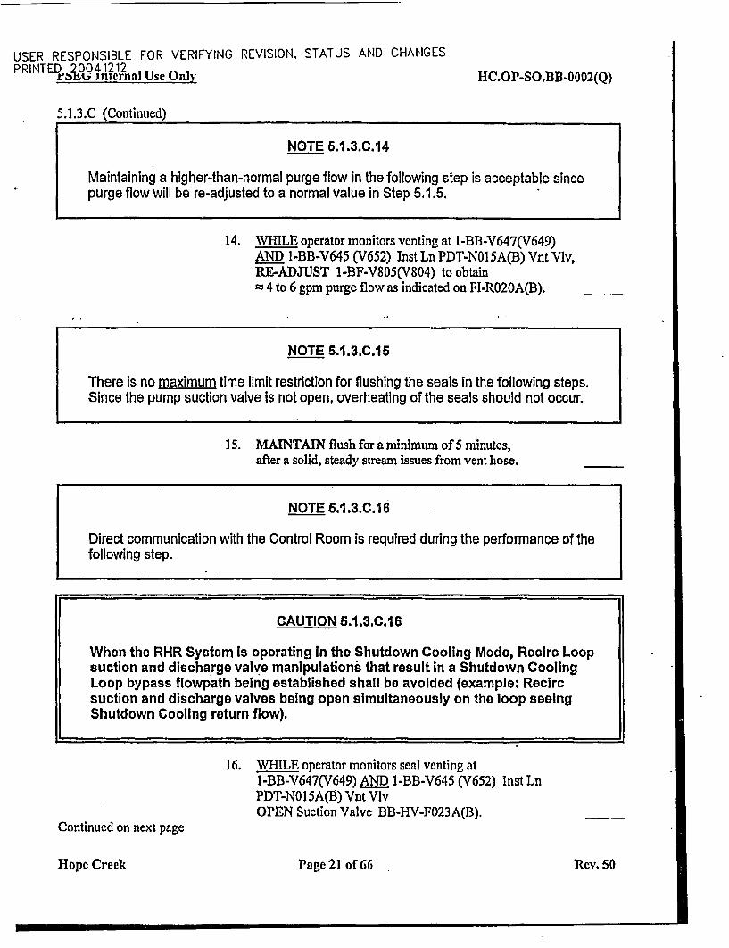
NOTE 6.1.3.C.14
Maintaining a higher-than-normal purge flow in the following step is acceptable sincepurge flow will be re-adjusted to a normal value in Step 5.1.5.
L_
14. WHILE operator monitors venting at l-BB-V647(V649)AND l-BB-V645 (V652) Inst Ln PDT-NOI 5A(B) Vnt VIv,RE-ADJUST I-BF-V805(V804) to obtain
4 to 6 gpm purge flow as indicated on FI-RO20A(B).
NOTE 5.1.3.C.15
There is no maximum time limit restriction for flushing the seals In the following steps.Since the pump suction valve is not open, overheating of the seals should not occur.
15. MAINTAIN flush for a minimum of 5 minutes,after a solid, steady stream issues from vent hose.
NOTE 6.1.3.C.16
Direct communication with the Control Room is required during the performance of thefollowing step.
CAUTION 5.1.3.C.1 6
When the RHR System Is operating In the Shutdown Cooling Mode, Recire Loopsuction and discharge valve manipulations that result in a Shutdown CoolingLoop bypass flowpath being established shall be avoided (example: Recircsuction and discharge valves being open simultaneously on the loop seeingShutdown Cooling return flow).
16. WHILE operator monitors seal venting atl-BB-V647(V649) AND I-BB-V645 (V652) Inst LnPDT-NO I 5A(B) Vnt VlvOPEN Suction Valve BB-HV-F023A(B).
Continued on next page
Hope Creek Page 21 of 66 Rev. 50
USER RESPONSIBLE FOR VERIFYING REVISION, STATUS AND CHANGESPRINTED 20041212r;, it internal Use Only HC.OP-SO.BB-0002(Q)
5.1.3.C (Continued)17. WHEN BB-HV-F023A(B) is fully OPEN,
AND AFTER ensuring a solid, steady stream of water isissuing from vent hose at 1-B1-V647(V649),THEN IMMEDIATELY CLOSE I-BB.V647(V649)AND I-BB-V645 (V652).
NOTE 6.1.3.C.18
The following step may be completed while continuing in this section.
18. COMPLETE the following:
a. CLOSE 1-BB-V648(V650).AND 1-BB-V646 (V651)InstLnPDT-NO15A(B)Vnt Viv.
b. REMOVE hoseAND CAP 1-BB-V647(V649)AND 1-BB-V645 (V652) InstLn PDT-NO15A(B)VntVlv.
CAUTION 6.1.3.C.19
For hot recirculation pump Seal Cavity venting (i.e., filled with ReactorCoolant System >2120 F) DO NOT leave vents open for > 6 minutes toprevent seal damage from overheating.
Reactor Pressure Vessel level should be monitored while performingthis following step.
19. PRIOR to starting the associated Recirc PumpVENT Recirc Pump A(B) Seal Cavity as follows:
a. SLOWLY OPEN I-BB-VO51 (1-BB-VO53)ANDI -313V050 (1-BB-V052), A(B) Recirc PumpSeal Cavity No. 1 vents.
b. CLOSE 1-BF-V805(1-BF-V804).Continued on next page
Hope Creek Page 22 of 66 Rev. 50
- |
USER RESPONSIBLE FOR VERIFYING REVISION, STATUS AND CHANGESPRINTED 20041212I., ±tiu al Use Only HC.OP-SO.BB-0002(Q)
5.1.3.C (Continued)c. AFTER A(B) Recirc Pump, No. 1 Seal Cavity vent
has been open for a minimum of five (5) minutesTHEN OPEN AND ADJUST 1-BF-V805(1-BF-V804),as necessary, to obtain a 4 to 6 gpm purge flow, asindicated on Fl-RO20A(B).
d. CLOSE 1-BB-V051 (1-BB-V053)and I -BB-VO50 (1 -BB-V052), A(B) Recirc PumpSeal Cavity No. 1 vents.
e. INSTALL a hose at l-BB-V285 (V287) A(B) RecircPump No.2 Cavity Vent Outboard ValveAND ROUTE to the Equipment Drain Sump.
f. Slowly OPEN I-BB-V284AND I-BB-V285(I-BB-V286 and 1-BB-V287)Recirc Pump No. 2 Cavity Vent Vlvs.
g. After all the air is removed,CLOSE 1-BB-V284and I-BB-V285(1-BB-V286 and 1-BB-V287)Recire Pump No. 2 Cavity Vent Vlvs.
h. REMOVE hose attached at 1-BB-V285 (1-BB-V287)A(B) Recirc Pump No. 2 Cavity Vent Outboard ValveAND INSTALL cap.
i. DOCUMENT completion of Recirc Seal Ventingin Control Room Log(s).
5.1.4 ENSURE, BB-HV-F023A(B) Suction ValveAND BG-HV-F100(F106) RWCUSuctionValveareOPEN.
NOTE 5.1.5
Approximately 30 minutes should be allowed to elapse between the completion ofStep 5.1.5 and the start of the pump, to allow the #2 Seal Cavity to self-vent through theseal stage flow line.
5.1.5 ADJUST I-BF-V805 (1-BF-V804) CRD Drive Water to Rx RecircPump A(B) Seal Purge throttle valve as necessaryUNTIL FI-RO20A(B) Rx Recirc Pump A(B) Seal Purge Flow indicates1.5 to 2.5 gpm (Local). [CD-405H]
Hope Creek Page 23 of 66 Rev. 50
USER RESPONSIBLE FOR VERIFYING REVISION, STATUS AND CHANGESPRINTEDO2OOt4J1J?2n Use Only HC.OP-SO.BB-0002(Q)
5.1.6 ENSURE the following:
* RECIRC PUMP A(B) SEAL COOLING FLOW LOW -Computer Point D2424(D2425) alarm is CLEAR.
* RECIRC PUMP MTR A(B) OIL LEVEL HI/LO - Computer PointD2922(D2923) alarm is CLEAR.
5.1.7 VERIFY no flow from the PSV-F025A(B) discharge piping.IF flow is identified from the discharge piping,THEN CONTACT engineering to calculate the required increasein seal purge flow. 170029861]
5.1.8 PREPARE the Reactor Recirc Pump for start as follows:
A. VERIFY that PUMP A(B) LOCKOUT BUS POWERAVAILABLE light is illuminated.
B. TURN handle on LF-173A(B) Rx Recire Motor Generator bladetype lube oil filter through several rotations to clear any blockage(Local).
C. PLACE the A(B) Oil Mist Eliminator in-serviceIAW section 5.8.
D. TEST DC oil pump auto start functionWITH NO AC oil pumps in service, as follows(Local Panel A(B)C158):
1. PLACE AUX LUBE OIL PUMP A(B)PI 13 Control Switchin AUTO.
2. VE RIFY START is ON.
3. PLACE AUX LUBE OIL PUMP A(B)PI 13 Control Switchin OFF.
Continued on next page
Hope Creek Page 24 of 66 Rev. 50
USER RESPONSIBLE FOR VERIFYING REVISION, STATUS AND CHANGESPRINTED 20041212
PSEG Internal Use OnlM IIC.OP-SO.BB-0002(Q)
5.1.8. (Continued)
CAUTION 6.1.8.E
The 1AIP120 AND 11P120, OR the 1A2P120 AND 1B2P120 oil pumps should notba run together, as they are powered off the same 480V Bus (10B130 and 10B140).A single 480'volt Bus trip may result In both MG Sets tripping.
E. START one of A1P120 (BIP120)OR A2P120 (B2P120) PUMP A(B) Auxiliaries Lube Oil Pumpfor Motor Generator to be started.
F. PRESS AUTO push button of other pump AIP120 (BIP120)OR A2P 120 (B2P120) PUMP A(B) Auxiliaries Lube Oil Pump.
G. PLACE AUX LUBE OIL PUMP A(B)P 113 Control Switchin AUTO (Local Panel A(B)CI 58).
H. VERIFY the following MG Set parameters:
1. Computer Point D2915 (D2916) RECIRC MG A(B)DRV LUBO PRESS is NOT in alarm.
2. Computer Point D2913 (D2914) RECIRC MG A(B)LUBE OIL TEMP is NOT in alarm.
I. VERIFY the following:
I . PUMP A(B) - MOT-GEN-FIELD BRKR TRIPPED is ON.
2. AU protectiveAND Generator Lockout relays are reset(Local Panel A(B)C158).
3. REACTOR RECIRC "A"("B") TROUBLE annunciatorCl-D4 (Cl-DS) is CLEAR.
4. PUMP B - RSP TK OVR is OFF.
Continued on next page
Hope Creekc Page 25 of 66 Rev. 50
USER RESPONSIBLE FOR VERIFYING REVISION, STATUS AND CHANGESPRINTED 20041212r;,htj internal Use Only IIC.OP-SO.B3B-0002(Q)
5.1.8 (Continued)
J. ENSURE RECIRC PUMP TRIP A(B)P201 PUMP MTRBRKR 1AN205 AND ICN205 (IBN205 AND IDN205)are CLOSED.
K. PRESS the following push buttons forREACTOR RECIRCULATION PUMP AAND PUMP B.
1. HIGH VIBRATION TRIP RESET.
2. SCOOP TUBE TRIP RESET (SCOOP TUBE LOCK UPlight goes OFF).
5.1.9 START the first idle Reactor Recirc Pump as follows:
NOTE 5.1.9.A
The limitations of Technical Specification 3.4.1.4 shall be observed prior to startingan idle Reactor Recirculation Pump.
A. Withih 15 minutes prior to starting pump,VERIFY temperature differential betweenReactor coolant within idle loopAND coolant in pressure vessel is < 50'F as indicated by:[T/S 4.4.1.4]
* Dome temperature calculated from REACTOR PRESSUREIAW HC.OP-DL.ZZ-0026(Q).
* RECIRC PUMP SUCTION LOOP A(B) TEMP IAWHC.OP-DL.ZZ-0026(Q).
B. LOG the above temperatures in HC.OP-DL.ZZ-0026(Q),Attachment 3v.
Continued on next page
Hlope Creek Page 26 of 66 Rev. 50
USER RESPONSIBLE FOR VERIFYING REVISION, STATUS AND CHANGESPRINTED 20041212VSM4 internal Use Only IIC.OP-SO.BB-0002(Q)
5.1.9 (Continued)
NOTE 5.1.9.C
To obtain a true bottom head drain temperature reading on Computer point A2942 one ofthe following conditions must be met.
The RWCU System must be in service withBG-H-V-Fl01 SUCT FROM RPV BOT DRN open.
* RHR must be in Shutdown Cooling with BG-HV-FIOO SUCT FROM A RECIRCLP OR BG-HV-F106 SUCT FROM B RECIRC LP open AND BG-HV-F102RECIRC LP SUCT HDR open AND BG-HV-Fl01 SUCT FROM RPV BOT DRNopen to obtain a true bottom head drain temperature
C. Within 15 minutes prior to starting pump,VERIFY temperature differential between Reactor coolant within domeAND bottom head drain is 5 1450F as indicated by: [T/S 4.4.1.4]
* Computer Point A2942-REAC ]OT HD DRN TEMP
• Dome temperature calculated from REACTOR PRESSUREIAW HC.OP-DL.ZZ-0026(QO.
D. LOG the above temperatures in HC.OP-DL.ZZ-0026(Q),Attachment 3v.
NOTE 5.1.9.E
IF the BP202 RHR Pump Is operating in Shutdown Cooling AND the AP201 ReactorRecirc Pump is to be placed in service, THEN performance of Step 5.1.9.E is NOTrequired.
E. .REMOVE the RHR System operating in the Shutdown Coolingmode from service.
Continued on next page
loype.Creek Page 27 of 66 Rev. 50
USER RESPONSIBLE FOR VERIFYING REVISION, STATUS AND CHANGESPRINTED 20041212rtazi internal Use Onlv IHC.OP-SO. BB -0002(Q)
5.1.9 (Continued)
CAUTION 6.1.9.F
WHEN the RHIR System is operating in the Shutdown Cooling Mode, Recirc Loopi.suction and discharge valve manipulations that result In a Shutdown Cooling Loopbypass flowpath being established shall be avoided (example: recirc suction anddischarge valves being open simultaneously on the loop seeing Shutdown Coolingreturn flow).
F. THROTTLE OPEN BB-HV-F031A(B) PUMPA(B)DISCHVALVE as necessary to increase loop temperatures (push buttonmust be pressed and held to effect valve opening.)
G. AFTER loop temperature requirements are satisfied,IF BB-HV-F031A(B) PUMP A(B) DISCH VALVE is open,THEN CLOSE BB-HV-FO31A(B) PUMP A(B) DISCH VALVE.
H. IF the 31B-HV-F03IA(B) PUMP A(B) DISCH VALVE hasNOT been opened to satisfy the loop temperature requirements,THEN CYCLE BB-HV-F03lA(B) PUMP A(B) DISCH VALVEas necessary to verify that the valve is not bound, ensuring valve isleft in the closed position after cycling.
I. ENSURE approximately 30 minutes have elapsed since completionof Step 5.1.5. This allows the #2 Seal Cavity to self-vent throughthe seal stage flow line.
J. ENSURE the temperature requirements of T/S 3.4.1.4 are satisfiedPRIOR to performing the following step(REFE RENCE Steps 5.1.9.A through D).
Continued on next page
Hope Creek . Page 28 of 66 Rev. 50
I-...
USER RESPONSIBLE FOR VERIFYING REVISION, STATUS AND CHANGESPRINTED 20041212r PAY internal Use Only tIC.OP-SO.BIB-0002(Q)
5.1.9 (Continued)
NOTE 5.1.9.K
The next step will startth d'r6epective Motor Generator Set and Recirculation Pump.The following should be observed to occur after starting:
A. Recirc Pump A(B) drive motor ammeter will increase to approximately3000 amps AND THEN decrease to approximately 200 amps.
B. Approximately 6 seconds after the MG set is started, the generator fieldbreaker will close.
C. The Recirc Pump speed will increase to approximately 50% of rated generatorspeed.
D. The Recirc Pump speed will decrease AND settle at approximately 20% ofrated speed.
;.....
CAUTION 6.1.9.K
During the transition from Shutdown Cooling operations to establishment ofnormal Reactor Recirculation System operations, the RHR System may be left inShutdown Cooling, only If BP202 Is the RHR Pump In service AND AP201 Is theReactor Recirculation Pump to be started.
K. PRESS REACTOR RECIRCULATION PUMP A(B) MOTORBRKR CLOSE push button.
L. VERIFY BB-HV-FO31A(B) REACTORRECIRCULATIONPUMP A(L) OSCH VALVE opens according to jog sequence(approximately 80 seconds for full travel).
M. RAISE Reactor Recirculation Pump Speed to 25% - 30%,to prevent erratic speed indications.170031631)
Continued on next page
Hopec Crock Page 29 of 66 Rev. 50
USER RESPONSIBLE FOR VERIFYING REVISION, STATUS AND CHANGESPRINTED ,2 0 rnal Use Only HC.OP-SO.BB-0002(Q)
5.1.9 (Continued)
CAUTION 6.1.9.N
Approximately 45 minutes may be required to stabilize motor-generator lube oiltemperatures during post-maintenance equipment starts. Control Roomtemperature recorders B31-TRR625 and CRIDS points D2911 and D2912 providepertinent parameter information and should be monitored for this duration. Localobservation should also be in place. [70031515]
N. ADJUST TACS flow to IAE-126 (IBE-126) MG Set A(B)Hydraulic Oil Cooler to maintain lube oil temperature between11 07F and 130'F as indicated on TI-8290 A(B) MG Set A(B)Lube Oil Temp (Local).
0. IF Shutdown Cooling was NOT terminated in Step 5.1 .9.E,AND the AP201 Reactor Recirc Pump is operating satisfactorily,THEN TERMINATE Shutdown Cooling IAWHC.OP-SOBC-0002(Q), Decay Heat Removal Operation.
5.1.10 START the second Reactor Recirc Pump as follows:
NOTE 6.1.10.A
The limitations of Technical Specification 3.4.1.4 shall be observed prior to starting anidle Reactor Recirculation Pump.
A. Within 15 minutes prior to starting pump,ENSURE, operating Loop flow is 5 (50% rated loop flow),as indicated on B31-FR-R614 RECIRC LOOP A / LOOP BFLOW. [TIS 4.4.1.4]
B. LOG FLOW in HC.OP-DL.ZZ-0026(Q), Attachment 3v.
C. Within 15 minutes prior to starting pump,ENSURE: temperature differential between idleAND operating Reactor Recirculation Loops is < 500F,IAW HC.OP-DL.ZZ-0026(Q). [T/S 4.4.1.4]
D. LOG temperatures in HC.OP-DL.ZZ-0026(Q), Attachment 3v.
Continued on next page
Hope Creek Page 30 of 66 Rev. 50
USER RESPONSIBLE FOR VERIFYING REVISION, STATUS AND CHANGESPRINTED 20041212
PSEG Internal Use Only HC.OP-SO.BB-0002(Q)
5.1.10 (Continued)
NOTE 5.1.10.E
The RWCU System must be in service with BG-HV-FIOI SUCT FROM RPV BOT DRNopen to obtain a true bottom head drain temperature reading on Computer Point A2942.
E. Within 15 minutes prior to starting pump,ENSURE temperature differential between Reactor coolant within domeAND bottom head drain is 5 1450F as indicated by the following:[T/S 4.4.1.4]
* Computer Point A2942-REAC BOT HD DRN TEMP
* Dome temperature calculated from REACTORPRESSURE,1AW HC.OP-DL.ZZ-0026(Q).
F. LOG temperatures in HC.OP-DL.ZZ-0026(Q), Attachment 3v.
G. THROTTLE OPEN BB-HV-FO31A(B) PUMP A(B) DISCHVALVE as necessary to increase loop temperatures (push buttonmust be pressed and held to effect valve opening).
H. AFTER loop temperature requirements are satisfied,IF BB-HV-FO31A(B) PUMP A(B) DISCH VALVE is open,THEN CLOSE BB-HV-F031A(B) PUMP A(B) DISCH VALVE.
I. IF the BB-HV-F03 1A(B) PUMP A(B) DISCH VALVE hasNOT been opened to satisfy the loop temperature requirements,THEN CYCLE BB-HV-FO31A(B) PUMP A(B) DISCH VALVEas necessary to verify that the valve is not bound, ensuring valve isleft in the closed position after cycling.
J. ENSURE approximately 30 minutes have elapsed since completionof Step 5.1.5. This allows the #2 Seal Cavity to self-vent throughthe seal stage flow line.
K. ENSURE the temperature requirements of T/S 3.4.1.4 are satisfiedPRIOR to performing the following step(REFERENCE Step 5.1.10.A through F).
Continued on next page
Hope Creek Page 31 of 66 Rev. 50
USER RESPONSIBLE FOR VERIFYING REVISION, STATUS AND CHANGESPRINTED 200412121DSUEG Internal Use Only 11C.OP-SO.BB-0002(Q)
5.1.10 (Continued)
NOTE 6.1.10.L
The next step will start the Trspective Motor Generator-Set AND Recirculation Pump.The following should be observed to occur after starting:
A. Recirc Pump A(B) drive motor ammeter will increase to approximately3000 amps AND THEN decrease to approximately 200 amps.
B. Approximately 6 seconds after the MG set is started, the generator fieldbreaker will close.
C. The Recirc Pump speed will increase to approximately 50% of ratedgenerator speed.
D. The Recirc Pump speed will decrease AND settle at approximately 20% ofrated speed.
L. PRESS REACTOR RECIRCULATION PUMP A(B)MOTOR BRKR CLOSE push button.
M. VERIFY BB-HV-F03lA(B) REACTORRECIRCULATIONPUMP A(B) DISCH VALVE opens according to jog-sequence(approximately 80 seconds for full travel).
N. RAISE Reactor Recirculation Pump Speed to 25% - 30%,to prevent erratic speed indications.[700316311
CAUTION 6.1.10.0
Approximately 45 minutes may be required to stabilize motor-generator lube oiltemperatures during post-maintenance equipment starts. Control Roomtemperature recorders B31-TRR625 and CRIDS points A2911 and A2912 providepertinent parameter Information and should be monitored for this duration. Localobservation should also be In place.
0. ADJUST TACS flow to lAE-126 (IBE-126) MG Set A(B)Hydraulic Oil Cooler to maintain lube oil temperature betweenI I°F and 1301F as indicated on TI-8290 A(B) MG Set A(B) LubeOil Temp (Local).
Hope Creek pCPage 32 of 66 - Rev. 50
USER RESPONSIBLE FOR VERIFYING REVISION, STATUS AND CHANGESPRINTED 20041212
I SE U Internal Use Only 11C.OP-SO.BB-0002(Q)
5.2 Reactor Recirculation System Tvo Loop Operation
5.2.1 ENSURE all prerequisites have been satisfied IAW Section 2.2.
5.2.2 PERFORM Manual Recirc Flow Control as follows:
NOTE 5.2.2.A
Recirc Pump speed can NOT be increased above Its minimum set point until Feedwaterflow is > 20% of its rated value.
A. MONITOR the following when changing Recire Pump speed:
* XR-R603AB,C,D - C51 (NEUTRON MONITORING)APRM
* B31-FR-R614 RECIRC LOOP A(B) FLOW
* FR-R61 1A(B) RECIRC LOOP A(B) JET PUMP FLOW
. PDR-R613/FR-R613 CORE PLATE DIFF PRESS/JETPUMP FLOW
B. RAISE OR LOWER Reactor Recirc Pump speed byintermittently pressing INCREASE OR DECREASE push buttonon SIC-R621A(B) PUMP A(B) SPD CONT.
5.2.3 ADJUST TACS flow to IAE-126 (IBE-126) MG Set A(B) HydraulicOil Cooler to maintain lube oil temperature between I 100F and 1300F asindicated on TI-8290 A(B) MG Set A(B) Lube Oil Temp (Local).
Hope Creek Page 33 of 66 Rev. 50
USER RESPONSIBLE FOR VERIFYING REVISION, STATUS AND CHANGESPRINTED 20041212
P'SEG Internal Use Only HC.OP-SO.BII1-0002(Q)
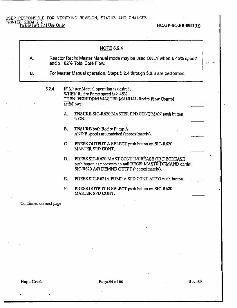
NOTE 5.2.4
A. Reactor Recirc Master Manual mode may be used ONLY when > 45% speedand s 102% Total Core Flow.
B. For Master Manual operation, Steps 5.2.4 through 5.2.6 are performed.
5.2.4 IF Master Manual operation is desired,WHEN Recirc Pump speed is > 45%,THEN PERFORM MASTER MANUAL Recirc Flow Controlas follows:
A. ENSURE SIC-R620 MASTER SPD CONT MAN push buttonis ON.
B. ENSURE both Recirc Pump AAND B speeds are matched (approximately).
C. PRESS OUTPUT A SELECT push button on SIC-R620MASTER SPD CONT.
D. PRESS SIC-R620 MAST CONT INCREASE OR DECREASEpush button as necessary to null RECIR MASTR DEMAND on theSIC-R620 A/B DEMND OUTPT (approximately).
E. PRESS SIC-R621A PUMP A SPD CONT AUTO push button.
F. PRESS OUTPUT B SELECT push button on SIC-R620MASTER SPD CONT.
Continued on next page
Hope Creek Page 34 of66 Rev. SO
USER RESPONSIBLE FOR VERIFYING REVISION, STATUS AND CHANGESPRINTED 20041212P IN J-%y .zianal Use OnIX HC.OP-SO.BB-0002(Q)
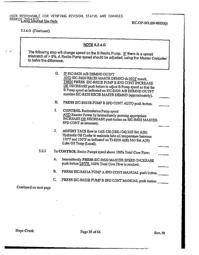
5.2.4.G (Continued)
NOTE 6.2.4.G
The following step will change speed on the B Recirc Pump. IF there is a speedmismatch of > 5%, A Recirc Pump speed should be adjusted, using the Master Controllerto halve the difference.
G. IF SIC-R620 A/B DEMND OUTPTAND SIC-R620 RECIR MASTR DEMND do NOT match,THEN PRESS -SIC-R621B PUMP B SPD CONT INCREASEOR DECREASE push button to adjust B Pump speed so that theB Pump speed as indicated on SIC-R620 A/B DEMND OUTPTmatches SIC-R620 RECIR MASTR DEMND (approximately).
H. r~Ess SIC-R621B PUMP B SPD CONT AUTO push button.
I. CONTROL Recirculation Pump speedAND Reactor Power by intermittently pressing appropriateINCREASE OR DECREASE push button on SIC-R620 MASTERSPD CONT as necessary.
J. ADJUST TACS flow to IAE-126 (IBE-126) MG Set A(B)Hydraulic Oil Cooler to maintain lube oil temperature between11 0°F and 1 30°F as indicated on T1-8290 A(B) MG Set A(B)Lube Oil Temp (Local).
5.2.5 To CONTROL RecircPumps speed above 100% Total Core Flow:
A. Intermittently PRESS SIC-R620 MASTER SPEED INCREASEpush button UNTIL 102% Total Core Flow is reached.
B. PRESS SIC-R621APUMP A SPD CONT MANUAL pusb button.
C. PRESS SIC-R621B PUMP B SPD CONT MANUAL push button.
Continued on next page
Hope Creek Page 35 of 66 Rev. 50
ON THE SPOT CHANGEPRINTED 20041212
IT IS THE RESPONSIBILITY OF THE USER TO VERIFY REVISION, STATUSPRINTED_ .20Aj.Q3.9l Use Only HC.OP-SO.1B1-0002(Q)
5.2.5 (Continued)
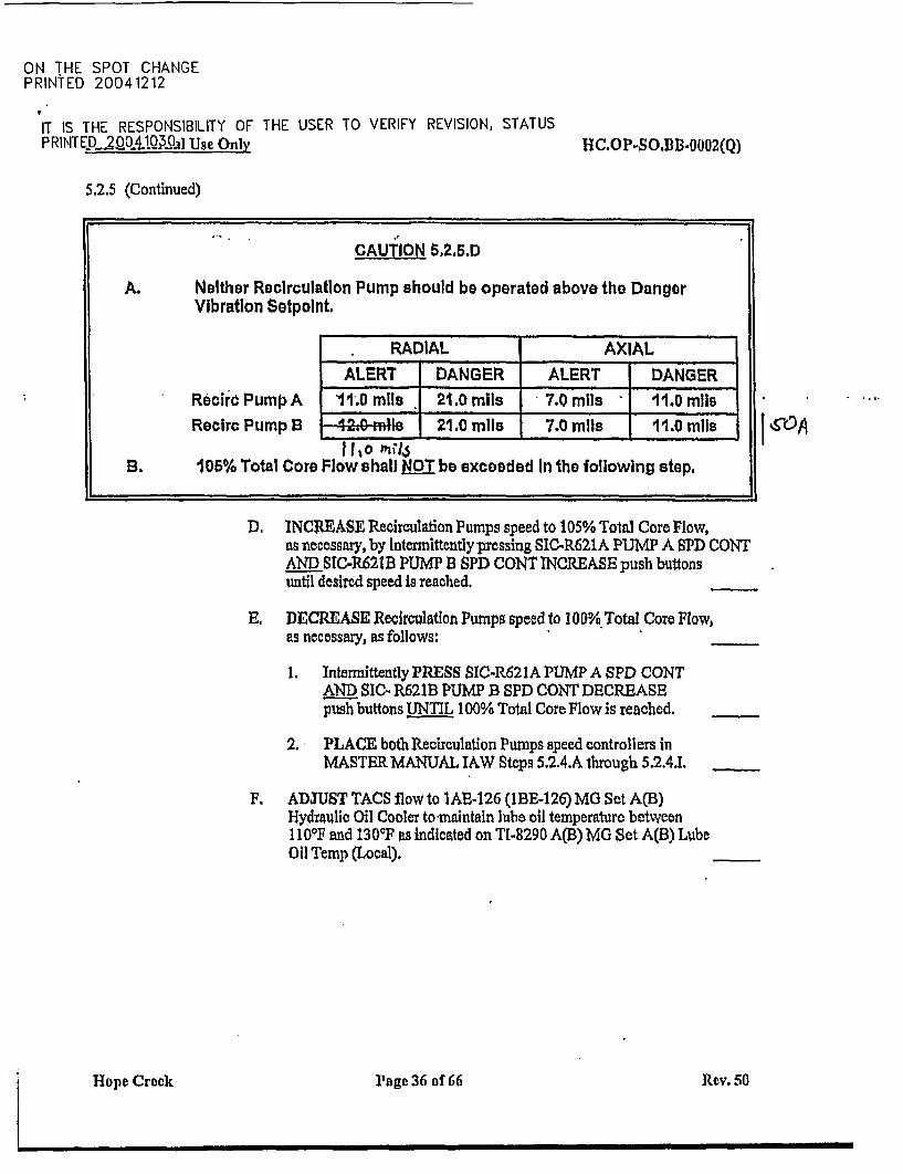
CAUTION 6.2.5.D
A. Neither Recirculatlon Pump should be operated above the DangerVibration Sotpolnt.
RADIAL AXIAL
ALERT DANGER ALERT DANGER
Recire Pump A 11.0 mils 21.0 mils 7.0 mils 11.j mIlsRecIrc Pump B -4.0 mJll 21.0 mil 7ls 11.0 mIls
11o ItosB. 105% Total Core Flow shall NOT be exceeded In the following step,
jWA.
D. INCREASE Recirculation Pumps speed to 105% Total Core Flow,as necessary, by Intermittently pressing SIC.R621A PUMP A SPD CONTAND SIC-R621B PUMP B SPD CONT INCREASE push buttonsuntil desired speed Is reached.
E. DECREASE Recirculation Pumps speed to I 00% .Total Core Flow,as necessary, as follows:
1. Intermittently PRESS SIC-R621A PUMP A SPD CONTAND SIC. R621B PUMP B SPD CONT DECREASEpush buttons UNTIL 100% Total Core Flow is reached.
2. PLACE both Recirculation Pumps speed controllers inMASTER MANUAL IAW Steps 5.2.4.A through 5.2.4.1.
F. ADJUST TACS flowto 1E-126 (BE-126)MG Set A(B)Hydraulic Oil Cooler to-maintain lube oil temperaturc between110°F and 130F as indicated on TI-8290 A(B) MG Set A(B) LubeOil Temp (Local).
Hopp, Crock Hkage 36 of 66 Rev. 50
I-
ON THE SPOT CHANGEPRINTED 20041212
IT IS THE RESPONSIBILITY OF THE USER TO VERIFY REVISION, STATUSPRINT ED OOl,4tJ Use Only IUC.OP-SO.BB-0002(Q)
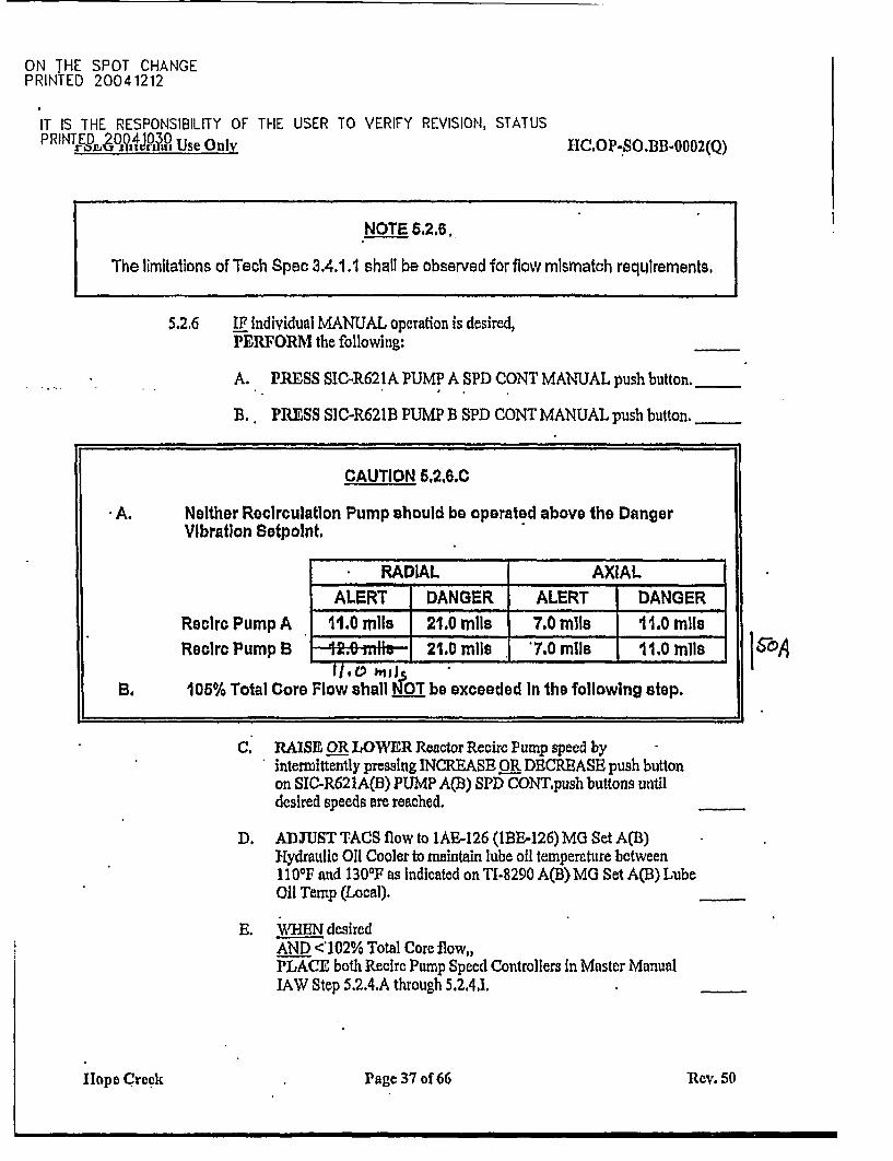
NOTE 8.2,6.
The limitations of Tech Spec 3.4.1.1 shall be observed for flow mismatch requirements.
5.2.6 IF Individual MANUAL operation is desired,PERFORMI the following:
A. PRESS SIC-R621A PUMP A SPD CONT MANUAL push button.
B.. PRESS S]C-R621B PUMP B SPD CONT MANUAL push button.
CAUTION 6,2.6.0
A. NeIther Recirculatlon Pump should be operated above the DangerVibration Sotpolnt.
RADIAL AXIALALERT DANGER ALERT DANGER
Rcire Pump A 11.0 mils 21.0 mIl il7.0 mils1.0 mileRecirc Pump B . 21.0 mile m11.0 mll
B. 105% Total Core Flow shall NOT be exceeded In the following stop.
C, RAISE OR LOWER Reactor Recirc Pump speed byintermittently pressing INCREASE OR DECREASE push buttonon SIC-R621A(B) PUMP A(B) SPD CONT.push buttons untildesired speeds are reached.
D. ADJUST TACS flow to IAE-126 (1B&126) MG Set A(B)Hydraulic Oil Cooler to maintain lube oil temperature between11 00F and 1300F as Indicated on TI-S290 A(B) MG Set A(B) LubeOil Temp (Local).
E. VHEN desiredAND <102% Total Core flow,,PLACE both Recirc Pump Speed Controllers in Master Manual1AW Step 5.2.4.A through 5.2,4.1.
I-ope Creek Page 37 of 66 Rev. 50
USER RESPONSIBLE FOR VERIFYING REVISION, STATUS AND CHANGESPRINTED 20041212
I'SEG Internal Use Only HC.OP-SO.BB-0002(Q)
5.3 Reactor Recirculation Single Loop Operation
NOTE 5.3
IF operating in Single Loop, the following actions must be taken to determineactual core flow:
A. IF the operating loop Recirc Pump speed is > 48% AND drive flow is> 23,000 gpm, THEN core flow indication can be taken from the flow recorder.
B. IF the operating loop recirc pump speed is < 48% speedAND < 23,000 gpm, THEN the flow In the idle loop is positive (forward) flow.The Idle loop jet pump flow AND the operating loop jet pump flow should beadded to obtain actual core flow.
CAUTION 6.3
A. IF operation Is to continue with one Recirculation Loop Shutdown, theLimitations of TIS 3.4.1.1 and surveillance requirement of TIS 4.4.1.2.bshall be observed. [TIS 4.4.1.2.b]
B. With the operable loop drive flow near 23 Kgpm (approximately 48% Pumpspeed), the flow through the Idle loop Is close to zero and will swap backand forth between forward and reverse flow. Operation can cause excessivejet pump vibration and the potential for consequent stress fatigue of theriser brace welds to the vessel. Operation In this area should be minimized.[80033270]
Hope Creek Page 38 of 66 Rev. 50
USER RESPONSIBLE FOR VERIFYING REVISION, STATUS AND CHANGESPRINTED 20041212r'Lti Internal Use Only HC.OP-SO.BB-0002(Q)
CAUTION 5.3.1
A. The Limitations of T/S 3.4.1.1 shall be observed prior to the shutdownof an operating Reactor RecIrc Pump during Operational Conditions IAND 2. Reactor Engineering AND Instrumentation and Controls haveprerequisites to satisfy prior to the commencement of single loopoperation. [TiS 3.4.1.1]
B. Instrumentation and Controls must reduce the APRM Scram and RodBlock Monitor Trip Setpoints and Allowable Values to those applicablefor single recirculation loop operation per Technical Specification 2.2.1,3.2.2, & 3.3.6. This must be done within 4 hours of commencing singlerecirculation loop operation. Compliance with Action Statements3.4.1.1.a.2, a.3 AND a.4 satisfies the APRM specifications in 2.2.1,3.2.2,and 3.3.6 unless an event other than single loop operations affects thesespecifications, In which case, those Action Statements must also beentered. ITIS 3.4.1.1]
C. IF operation Is to continue with one Recirculation Loop Shutdown, theLimitations of TIS 3.4.1.1 and surveillance requirement of TIS 4.4.1.2.bshall be observed. [T/S 4.4.1.2.b]
;i
5.3.1 ENSURE all prerequisites have been satisfied 1AW Section 2.3.
5.3.2 NOTIFY Instrumentation and Controls thatihey have 4 hours to reduceAPRM Scram and Rod Block Monitor Trip Setpoints and AllowableValues in accordance with Technical Specification 3.4.1.1. [TIS 3.4.1.1]
Hope Creek Page 39 of 66 Rev. 50
USER RESPONSIBLE FOR VERIFYING REVISION, STATUS AND CHANGESPRINTED 20041212
PSEG Internal Use Only HC.OP-SQ.I)B-0002(Q)
CAUTION 5.3.3
A. Power-to-Flow Maps should be observed while decreasing power andprior to removing the recirculation pump from service. [ReferenceAttachment 11
B. Core flow must be maintained > 40% during single loop operations toprevent cooldown of the idle loop.
C. With NO Recirc Pumps In service in Operational Condition 1,the Reactor shall be manually scrammed.
5.3.3 REDUCE Reactor Power by decreasing core flow and/or insertingcontrol rods IAW Reactor Engineering instructions.
5.3.4 TRANSFER Reactor Recirc Pump AAND B control to Manual Recirc Flow Control by pressing SIC-R621A
* AND B PUMP A AND B SPD CONT MAN push buttons.
5.3.5 SIMULTANEOUSLY PERFORM the following two steps:
* On the pump remaining in-service,INTERMITTENTLY PRESS SIC-R621B(A) PUMP B(A)SPD CONT INCREASEIDECREASE push buttonUNTIL desired speed is reached,THEN RELEASE.
* On the pump being removed from service,INTERMITTENTLY PRESS SIC-R621A(B) PUMP A(B)SPD CONT DECREASE push buttonUNTIL minimum speed is reached,THEN RELEASE.
5.3.6 PRESS PUMP A(B) MOTOR BRKR TRIP push button.
Holpe Cr-eck Page 40 of 66 Rev. 50
USER RESPONSIBLE FOR VERIFYING REVISION, STATUS AND CHANGESPRINTED 20041212rst jinternal Use Only I1C.OP-SO.BB-0002(Q)
NOTE 5.3.7
A. IF BB-HV-F031A(B) can NOT be opened in the following step, then Step 5.3.8must be performed. Otherwise, Step 5.3.8 may be disregarded.
B. BB-H1-F031A(B) PUMP A(B) DISCH VALVE should be left closed followingthe 5 minutes IF Shutdown Cooling Is to be placed in service or for pumpmaintenance that requires the discharge valve to remain closed. [CD-976B]
5.3.7 CLOSE BB-HV-F031A(B) PUMP A(B) DISCH VALVE forapproximately 5 minutes,THEN RE-OPEN the valve to keep the loop Temperature within 50 0Fof the Reactor coolant temperature (push button must be pressed and heldto effect valve opening). [CD-976B]
5.3.8 IF BB-HV-F03lA(B) PUMP A(B) DISCH VALVE can NOT beopened (loop remains isolated),THEN RECORD the time isolated in HC.OP-DL.ZZ-0026(Q),Surveillance Log, Attachment 3v (T/S item 4.4.1.1.2.c),AND INFORM System Engineering.
Continued on next page
Hope Creek Page 41 of 66 Rev. 50
USER RESPONSIBLE FOR VERIFYING REVISION, STATUS AND CHANGESPRINTED 2 0 2,4A1?1.nal Usc Only HC.OP-SO.BB-0002(Q)
5.3 (Continued)
NOTE 5.3.9
A. Recirc Flow control must remain in local Manual Mode,'THERMAL POWER'must remain < 70% of Rated AND Recirc Pump speed must remain < 90% ofrated pump speed (90% of rated pump speed Is 79% indicated), whileoperating with a single recirc loop in service.
B. IF core flow can NOT be increased above 40% in the following step OR dropsbelow 40%, then Step 5.3.10 must be performed. Otherwise, Step 5.3.10 maybe disregarded.
CAUTION 5.3.9
A. The lImitations of Tech Spec 3.4.1.1 shall be observed during OperationalConditions I AND 2 with a single recirculation loop in service.
B. Core flow must be maintained > 40% during single loop operations toprevent cooldown of the Idle loop.
5.3.9 INCREASE core'flow to > 40% of rated core flow,as required. Recirculation Pump speedAND Reactor Power are now controlled by pressingthe appropriate INCREASEOR DECREASE push button on SIC-R621B(A) Pump B(A)SPD CONT as necessary.
5.3.10 IF core flow can NOT be increased above 40% OR drops below 40%,THEN RECORD the time in HC.OP-DL.ZZ-0026(Q),Surveillance Log, Attachment 3v (T/S 3.4.1. 1, ACTIONS c and d),AND INFORM System Engineering.
Hope Creek Page 42 of 66 Rev. 50
USER RESPONSIBLE FOR VERIFYING REVISION, STATUS AND CHANGESPRINTED 20041212rSEL internal Use Only HC.OP-SO.BB-0002(Q)
5.3.11 IF the MG Set A(B) Lube Oil system associated with the Recirc Pumpremoved from service is itself to be removed from service,THEN PERFORM the following:
A. ENSURE Motor-Generator set A(B) has stopped turning (Local).
B. PRESS MAN push button of PUMP A(B) AUXILIARIESLUBE OIL PUMP AlP120(BP120)OR A2PI20(BP120) which was in standby.
C. PLACE the (Local) control switch for AP-1 13(BP-1 13)Emergency Lube Oil Pump in OFF.
D. AFTER MG Set lube oil temperature has decreased to < 1100 Fas indicated on TI-8290A(B) MG Set A(B) Lube Oil Temp,STOP PUMP A(B) AUXILIARIES LUBE OIL PUMPA1Pl20(BIPl20) OR A2Pl20(B2P120).
E. STOP Fluid Coupler Oil Mist Eliminator IA(B)VI35 (Local)AND/OR REMOVE Oil Mist Eliminator IA-V-136IAW section 5.8.
5.3.12 IF the MG Set A(B) Lube Oil System was left in service,THEN ADJUST TACS flow to IAE-126 (lBE-126)MG Set A(B)Hydraulic Oil Cooler to maintain lube oil temperature ibetweenI 100F and 1300F as indicated on TI-8290 A(B) MG Set A(B) LubeOil Temp (Local).
5.3.13 IF Reactor Recirc Pump isolation is desired,THEN REFER to Section 5.6, Reactor Recirculation System Shutdown.
5.3.14 WHEN ready to return the second Recirc Pump to service,THEN REFER to Section 5.1, Reactor Recirculation System Startup.
Hop~e Crcok Page 43 of 66 Rev. 50
USER RESPONSIBLE FOR VERIFYING REVISION, STATUS AND CHANGESPRINTED 20041212
PSEG Internal Use Only HC.OP-SO.BB-0002(Q)
5.4 Resetting Reactor Recirculation Pump Runback
CAUTION 5.4
A. WHEN a scoop tube is locked up, a recirculation runback may create alarge flow mismatch. Timely action must be taken to match loop flowsby either resetting the runback, if possible, AND increasing the flow Inthe runback loop OR-by unlocking the scoop tube to lower flow in thelocked up loop. IF action cannot be taken In a timely manner, the RecircPump In the low flow (unlocked) loop should be tripped.
* B. IF BOTH pumpseare NOT In manual prior to attempting to reset a'runback, unwanted reactivity manipulationipower decrease may occur.
5.4.1 ENSURE all Prerequisites have been satisfied IAW Section 2.4.
5.4.2 ENSURE BOTH SIC-R621A PUMP A SPD CONT is in MANAND SIC-R621B PUMP B SPD CONT is in MAN.
5.4.3 ENSURE the A/B DEMND OUTPT on SIC-R620 MASTER SPD CONTis less than or equal to the SPEED DEMAND indicated on SIC-R621 A(B)PUMP A(B) SPD CONT by performing the following:
A. PRESS OUTPUT A(B) SELECT on SIC-R620 MASTERSPD CONT.
B. REDUCE A/B DEMND OUTPT on SIC-R620 MASTER SPDCONT by pressing the DECREASE push button on SIC-R621 A(B)PUMP A(B) SPD CONT until the A/B DEMND OUTPT on theSIC-R620 MASTER SPD CONT is less than or equal to the SPEEDDEMAND on SIC-R621 A(B) PUMP A(B) SPD CONT.
C. REDUCE SIC-R620 MASTER SPD CONT RECIR MASTRDEMND to match A/B DEMND OUTPT (approximately).
5.4.4 PRESS the following for Reactor Recirc Pump A(B):
A. INTMD RUNBACK RESET push button
B. FULL RUNBACK RESET push button
TIope Crock Page 44 of 66 Rev. 50
USER RESPONSIBLE FOR VERIFYING REVISION, STATUS AND CHANGESPRINTED 20041212
I IU internal Use Only HC.OP-SO.BB-0002(Q)
5.5 Scoop Tube Positioner Lockup Operation
CAUTION 5.5
WHEN a scoop tube is locked up, a recirculation runback may create a large flowmismatch. Timely action must be taken to match loop flows by either resetting therunback, if possible, AND Increasing the flow In the runback loop OR by unlockingthe scoop tube to lower flow in the locked up loop. IF action cannot be taken in atimely manner, the Recirc Pump In the low flow (unlocked) loop should be tripped.
5.5.1 ENSURE all Prerequisites have been satisfied IAW Section 2.5.
NOTE 5.5.2
This step is written for routine transfer to the Lockup position AND is NOT to be used foran emergency lockup.
5.5.2 PERFORM the following to lock up the Reactor Recirc PumpMotor/Generator Scoop Tube Positioner:
A. PRESS SIC-R621AAND B PUMP A AND B SPD CONT MAN push buttons.
B.. EQUALIZE A AND B Recirc Pump Speeds byincreasing OR decreasing pump speeds with SIC-R621AAND B PUMP A AND B SPD CONT while maintainingconstant Reactor Power.
C. .PRESS SCOOP TUBE TRIP push button A(B)AND ENSURE SCOOP TUBE LOCKUP light comes onfor the desired Motor/Generator.
flope Creek oPage 45 of 66 Rev. 50
USER RESPONSIBLE FOR VERIFYING REVISION, STATUS AND CHANGESPRINTED 20041212
i',iSi.. internal Use Only HC.OP-SO.BB-0002(Q)
NOTE 6.6.3
Operation of the Scoop Tube Controller locally shall be performed by a LicensedOperator.
5.5.3 PERFORM the following to manually control the speed of ReactorRecirc Pump A(B) from the Scoop Tube Positioner (Local):
A. REQUEST NCO in the Main Control Room to maintain constantcommunications while adjusting pump speed.
CAUTION 5.6.3.Bl
The Scoop Tube Positioner should not be manually positioned unless the ScoopTube Positioner power switch Is OFF.
B. PLACE Reactor Recirc A(B) Scoop Tube Positionerpower switch in OFF.
C. REMOVE handcrank from inside Positioner on mounting bracket-
D. INSTALL handcrank on shaft.
NOTE 6.6.3.E
A firm grip must be applied to the handcrank before releasing the Brake to prevent theload from driving through the Control Drive.
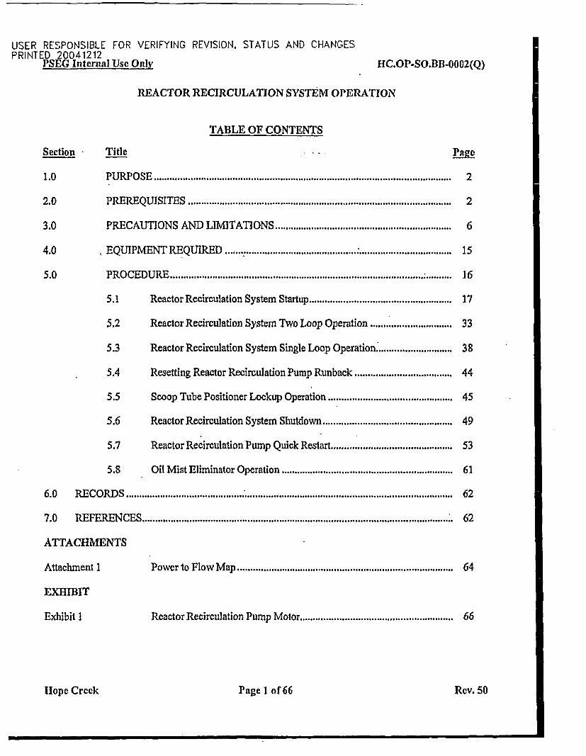
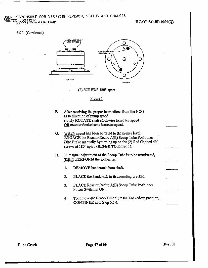
-E. DISENGAGE the Reactor Recirc A(B) Scoop Tube Positioner Disc.Brake manually by turning down on the (2) Red Capped dial screwsat 180° fpart (REFER TO Figure 1).
Continued on next page
Hope Creek Page 46 of 66 Rev. 50
USER RESPONSIBLE FOR VERIFYING REVISION. STATUS AND CHANGESPRINTED[ 2004 212nal Use Only HC.OP-SO.BB-0002(Q)
5.5.3 (Continued)
CAME ta APART
rn< W DJ
- "rrn" f,
Mr _r _ .M
-
L 1
GDE VIEW
loP VIEW
(2) SCREWS 180° apart
Figure 1
F. After receiving the proper instructions from the NCOas to direction of pump speed,slowly ROTATE shaft clockwise to reduce speedOR counterclockwise to increase speed.
0. WHEN speed has been adjusted to the proper level,ENGAGE the Reactor Recirc A(B) Scoop Tube PositionerDisc Brake manually by turning up on the (2) Red Capped dialscrews at 1800 apart (REFER TO Figure 1).
H. IF manual adjustment of the Scoop Tube is to be terminated,THEN PERFORM the following:
1. REMOVE handcrank from shaft.
2. PLACE the handcrank in its mounting bracket.
3. PLACE Reactor Recirc A(B) Scoop Tube PositionerPower Switch in ON.
4. To remove the Scoop Tube from the Locked-up position,CONTINUE with Step 5.5.4.
Hope Creek Page 47 of 66 Rev. 50
USER RESPONSIBLE FOR VERIFYING REVISION, STATUS AND CHANGESPRINTED 20041212trS.Li i internal Use Only HC.OP-SO.I]B-0002(Q)
5.5.4 To unlock the Reactor Recirc Pump Motor/GeneratorScoop Tube Positioner,PERFORM the following:
NOTE 5.5.4.A
IF the Scoop Tube Lockup condition was a result of either:(1) reaching the electrical stops OR(2) pressing the Scoop Tube Trip push button, AND NO manual speed adjustments
have been made, THEN Step 5.5.4A should NOT be performed (continue atStep 5.5.4.B).
A. VERIFY the Reactor Recirc A(B) Scoop Tube Positioner DiscBrake is engaged manually by turning up on the (2) Red Cappeddial screws at 1800 apart (SEE Figure 1).
NOTE 6.5.4.Bl
Speed demand will drift continuously and care must be used when Scoop TubeLockup is reset.
B. PRESS SIC-R621A(B) PUMP A(B) SPD CONT INCREASEOR DECREASE push button as necessary to null indicated speed onSIC-R621A(B) with associated pump output signal at A/B DEMNDOUTPT on SIC-R620 MASTER SPD CONT.
NOTE 6.5.4.C
A small speed change of c 5% may be experienced when coming out of Lockup.
CAUTION 5.5.4.C
When coming out of Scoop Tube Lockup, the potential exists for the Reciro Pumpto "Run Away", and the operator should be prepared to take appropriate action.
C. WHEN SIC-.R621A(B) PUMP A(B) SPD CONT SPEEDDEMAND indicator is slightly less than indicated speed,PRESS SCOOP TUBE TRIP RESETAND ENSURE SCOOP TUBE LOCK-UP light goes off.
D. ADJUST speed(s) as necessary.
Hop~e Creek Page 48 of 66 Rev. 50
USER RESPONSIBLE FOR VERIFYING REVISION, STATUS AND CHANGESPRINTED 2 004 12 12nat Use Only HC.OP-SO.IB-0002(Q)
5.6 Reactor Recirculation System Shutdown
NOTE 5.6
IF shutdown of the Reactor Recirculation System is to be performed to accommodateplacing Shutdown Cooling in operation, consideration may be given to maintainingReactor Recirculation in service to provide forced core flow until the required RHR flow isachieved. During the transition from normal Reactor Recirculatlon System operations toestablishment of Shutdown Cooling, only the AP201 Reactor Recirculation Pump may beleft in operation until the BP202 RHR pump is operating satisfactorily, AND then only untilthe required B RHR Loop flow of 10, 000 gpm Is achieved.
..
.,
CAUTION 5.6.1
A. The limitations of Tech Spec 3.4.1.1 shall be observed prior to theshutdown of an operating Reactor Recirc Pump during OperationalConditions I and 2.
B. With NO Recirc Pumps In service and In Operational Condition 1,I' then the Reactor shall be manually scrammed
5.6.1 ENSURE all prerequisites have been satisfied 1AW Section 2.6.
5.6.2 REDUCE Reactor Power by decreasing core flow and/or insertingcontrol rods 1AW Reactor Engineering instructions.
5.6.3 TRANSFER Reactor Recirc Pump A*AND B control to Manual Recirc Flow Control by pressing SIC-R621AAND B.PUMP A AND B SPD CONT MAN push buttons.
5.6.4 PRESS SIC-R621A(B) PUMP A(B). SPD CONTDECREASE push button UN1lL minimum speed is reached.
5.6.5 PRESS PUMP A(B) MOTOR BRKR TRIP push button.
Hope Creek Page 49 of 66 Rev. 50
USER RESPONSIBLE FOR VERIFYING REVISION, STATUS AND CHANGESPRINTED " 4 iaiunal Use Only IIC.OP-SO.BB-0002(Q)
CAUTION 5.6.6
BB-HV-F031A(B) PUMP A(B) DISCH VALVE should be left closed followingthe 5 minutes IF Shutdown Cod1irg 'id to be placed in service OR for pumpmaintenance that requires the discharge valve to remain closed. [CD-976B]
5.6.6 CLOSE BB-HV-F031A(B) PUMP A(B) DISCH VALVEfor approximately 5 minutes,THEN RE-OPEN BB-HV-F03 IA(B) to keep the loop temperaturewithin 50'F of the reactor coolant temperature (push button must bepressed and held to effect valve opening). [CD-976B]
5.6.7 IF the MG Set A(B) Lube Oil system is to be removed from service,THEN PERFORM the following:
A. ENSURE Motor-Generator Set A(B) has stopped turning (Local).
B. PRESS MAN push button of PUMP A(B) AUXILIARIESLUBE OIL PUMP AlP120(B1P120)OR A2P120(B2P120) which was in standby.
C. PLACE the (local) control switch for AP-1 13(BP-1 13)the Emergency Lube Oil Pump in OFF.
D. AFTER the MG Set lube oil temperature has decreased to < IIOTFas indicated on TI-8290A(B) MG Set A(B) Lube Oil Temp,STOP PUMP A(B) AUXILIARIES LUBE OIL PUMPAlP120(BIP120) OR A2P120(B2P120).
E. STOP Fluid Coupler Oil Mist Eliminator IA(B)V135 (Local)AND/OR REMOVE Oil Mist Eliminator 1A-V-136IAW section 5.8.
5.6.8 IF the MG Set A(B) Lube Oil system was left in service,THEN ADJUST TACS flow to IAE-126 (lBE-126) MG Set A(B)Hydraulic Oil Cooler to maintain lube oil temperature betweenI 100F and 1300F as indicated on TI-8290 A(B) MG Set A(B) LubeOil Temp (local).
Hope Creek Page 50 of 66 Rev. 50
USER RESPONSIBLE FOR VERIFYING REVISION, STATUS AND CHANGESPRINTED 20041212r"11'u internal Use Only HC.OP-SO.BB-0002(Q)
CAUTION 6.6.9
A. Closure of both Reactor Recirc Pump suction valves will result in a loss'. of suction to the Reactor Water Cleanup System, unless the RWCU
bottom head suction path is established.
B. To avoid over-pressurizing and overcooling the pump casing, the SealPurge Water for the Reactor Recirc Pump seals must be secured prior toisolating the pump. [CD-219B]
5.6.9 IF isolation of Reactor Recirc Pump A(B) is desired,THEN PERFORM the following:
A. CLOSE l-BF-V805(V804) CRD Drive Water Filter toRecirc Loop A(B) to prevent lifting relief valve.
B. CLOSE 1-BF-Vl00 (101) RX RECIRC PUMP A(B) CRDSEAL ISLN.
C. UNCAP AND INSTALL a hose at l-BF-V156 (V773) RecircPmps Seal Purge Supply Hdr Vent Vlv(Torus Access, Rm. 4223 (4321 Pipechase))AND ROUTE to nearest floor/equipment drain.
D. OPEN 1-BF-VI55 (V772) Recirc Pmps Seal Purge SupplyHdr Vent Vlv.
E. OPEN 1-BF-V1 56 (V773) Recire Pmps Seal Purge SupplyHdr Vent Vlv.
F. CLOSE BF-HV-3800A(B) SEAL PURGE WTR VALVE.
G. CLOSE BB-HV-F023A(B) SUCTION VALVE.
H. ENSURE BB-HV-FO31A(B) PUMP DISCH VALVE isCLOSED.
I. CLOSE BG-HV-Fl00(Fl06) RWCU SUCTION VALVE.
J. CLOSE I -BB-V042(V046) Seal Purge Manual Isolation.
Continued on next page
Hopec Creek Page 51 of 66 Rev. 50
USER RESPONSIBLE FOR VERIFYING REVISION, STATUS AND CHANGESPRINTED 2 00 4II2?Inal Use Only HC.OP-SO.BB-0002(Q)
5.6.9 (Continued)K. OPEN 1-BB-V050(V052)
AND l-BB-V051(V053) Seal Vent.
L. ~II pump draining is required (for seal replacement, the pumpis kept full for shielding),THEN PERFORM the following:
1. OPEN 1-BG-V167(V169)AND l-BG-V168(V170) Pump Drains.
2. OPEN I-BB-V647(V681)AND 1-BB-V648(V682).
M. CLOSE I-ED-VO23(VO24)AND 1-ED-V025(V026) RACS Isolation Valves.
Hope Creek Page 52 of 66 Rev. 50
USER RESPONSIBLE FOR VERIFYING REVISION, STATUS AND CHANGESPRINTED 20041212
PLSME Internal Use Only HC.OP-SO.BB-0002(Q)
NOTE 5.7
A. This subsection may be used to restart one or both Reactor Recirc Pumps toprevent thermal stratification following a plant transient, but only when InOperational Condition 3 or 4. [700315151
B. This subsection should not be used if the Recirc System has been out ofservice for an extended period as determined by the SMICRS.
C. All operations are performed from 10C651 Section C unless otherwise noted.
5.7 Reactor Recirculation Pump Quick Rcstart
5.7.1 ENSURE all prerequisites have been satisfied lAW Section 2.7. .
5.7.2 ENSURE Reactor level is greater than +30 inches to ensureadequate NPSH is available.
5.7.3 VERIFY BB-HV-F023A(B) SUCTION VALVEAND BG-HV-FlOO(F106) RWCU SUCTION VALVE are OPEN.
5.7.4 PREPARE the Reactor Recirc Pump for start as follows:
A. VERIFY that PUMP A(B) LOCKOUT BUS POWERAVAILABLE light is illuminated.
B. VERIFY the following MG Set parameters:
1. Computer Point D2915 (D2916) RECIRC MG A(B)DRV LUBO PRESS is NOT in alarm.
2. Computer Point D2913 (D2914) RECIRC MG A(B)LUBE OIL TEMP is NOT in alarm.
Continued on next page
Hop~e Creek Page 53 of 66 Rev. 50
USER RESPONSIBLE FOR VERIFYING REVISION, STATUS AND CHANGESPRINTED 20041212r~bE intcrnal Use Only IIC.OP-SO.BB-0002(Q)
5.7.4 (Continued)
C. VERIFY the following:
1. PUMP A(B) - MOT-GEN-FIELD BRKR TRIPPED is ON.
2. All protectiveAND Generator Lockout relays are reset(Local Panel A(B)C158).
3. REACTOR RECIRC "A"("B") TROUBLE annunciatorC1-D4 (CI-D5) is CLEAR.
4. PUMP B - RSP TK OVR is OFF.
D. IF RECIRC PUMP TRIP A(B)P201PUMP MTR BRKR IAN205AND 1CN205 (IBN205 AND 1DN205) have TRIPPED,THEN PERFORM the following:
I. ENSURE the following switches are in BYP:
* C71-512ARECIRC PUMP TRIP SYSTEM A DISABLE.
* C71-512BRECIRC PUMP TRIP SYSTEM B DISABLE.
2. ENSURE RRCS is RESET.
3. CLOSE RECIRC PUMP TRIP A(B)P201PUMP MTR BRKR 1AN205.AND ICN205 (IBN205 AND IDN205).
E. PRESS the following push buttons forREACTOR RECIRCULATION PUMP AAND PUMP B.
1. HIGH VIBRATION TRIP RESET.
2. SCOOP TUBE TRIP RESET (SCOOP TUBE LOCK UPlight goes off).
Hople Creek Page 54 of 66 Rev. 50
USER RESPONSIBLE FOR VERIFYING REVISION. STATUS AND CHANGESPRINTED 20041212r"Jt~ internal Use Only HiC.OP-SO.BB-0002(Q)
5.7.5 IF desired,START the first idle Reactor Recirc Pump as follows(A Reactor Recirc Pump is preferred):
NOTE 6.7.5.A-
The limitations of Technical Specification 3.4.1.4 shall be observed prior to starting an idleReactor Recirculation Pump.
A. Within 15 minutes prior to starting pump,VERIFY temperature differential between Reactor coolantwithin idle loop AND coolant in pressure vessel is < 50 0Fas indicated by: [T/S 4.4.1.4]
1. Dome temperature calculated from REACTOR PRESSUREIAW HC.OP-DL.ZZ-0026(Q).
2. RECIRC PUMP SUCTION LOOP A(B) TEMP 1AWlIC.OP-DL.ZZ-0026(Q).
B. LOG the above temperatures in HC.OP-DL.ZZ-0026(Q),Attachment 3v.
Continued on next page
Hope Creek Page 55 of 66 Rev. 50
USER RESPONSIBLE FOR VERIFYING REVISION, STATUS AND CHANGESPRINTED 20041212
PSEG Internal Use Only HC.OP-SO.B13-0002(Q)
5.7.5 (Continued)
NOTE 5.7.5.C
The RWCU System must be In service with BG-HV-Fl01 SUCT FROM RPV BOT DRN -open to obtain a true bottom head drain temperature reading on Computer point A2942.
C. Within 15 minutes prior to starting pump,VERIFY temperature differential between Reactor coolant within domeAND bottom head drain is • 145 0F as indicated by:[T/S 4.4.1.4]
1. Computer Point A2942-REAC BOT HD DRN TEMP
2. Dome temperature calculated from REACTOR PRESSUREIAW HC.OP-DL.ZZ-0026(Q).
D. LOG the above temperatures in HC.OP-DL.ZZ-0026(Q),Attachment 3v.
E. After loop temperature requirements are satisfied,IF BB-HV-F031A(B) PUMP A(B) DISCH VALVE is open,TIEN CLOSE BB-HV-F031A(B) PUMP A(B) DISCH
VALVE.
F. ENSURE the temperature requirements of TechnicalSpecification 3.4.1.4 are satisfied prior to performing thefollowing step.
Continued on next page
Hope Creek Page 56 of 66 Rtev. 50
USER RESPONSIBLE FOR VERIFYING REVISION, STATUS AND CHANGESPRINTED 20041212
PSEG Internal Use Only HC.OP-SO.IBB-0002(Q)
5.7.5 (Continued)
NOTE 5.7.5.G
The next step will start the respective Motor Generator Set AND Recirculation Pump.The following should be observed to occur after starting:
A. Recirc Pump A(B) drive motor ammeter will increase to approximately3000 amps AND THEN decrease to approximately 200 amps.
B. Approximately 6 seconds after the MG set is started, the generator fieldbreaker will close.
C. The Recirc Pump speed will increase to approximately 50% of rated generatorspeed.
D. The Recirc Pump speed will decrease AND settle at approximately 20% ofrated speed.
---- -- - - - ---
G. PRESS REACTOR RECIRCULATION PUMPA(B) MOTOR BRKR CLOSE push button.
H. VERIFY BB-HV-FG31A(B) REACTOR RECIRCULATIONPUMP A(B) DISCH VALVE opens according to jog sequence(approximately 80 seconds for full travel).
I. ADJUST TACS flow to IAE-126 (lBE-126) MG Set A(B)Hydraulic Oil Cooler to maintain lube oil temperature between110 F and 130 0F as indicated on TI-8290 A(B) MG Set A(B)Lube Oil Temp (Local).
Hope Creek Page 57 of 66 Rev. 50
USER RESPONSIBLE FOR VERIFYING REVISION, STATUS AND CHANGESPRINTED 20041212';iSi internal Use Only 11C.OP-SO.BB-0002(Q)
5.7.6 IF desired,START the second Reactor Recirc Pump as follows:
NOTE 6.7.6.A
The limitations of TechnicalrSpecification 3.4.1.4 shall be observed priorto;starting anidle Reactor Recirculation Pump.
A. Within 15 minutes prior to starting pump,ENSURE operating Loop flow is 5 (50% rated loop flow),as indicated on B3 I -FR-R614 RECIRC LOOP A / LOOP BFLOW. [T/S 4.4.1.4]
B. LOG FLOW in HC.OP-DL.ZZ-0026(Q)j Attachment 3v.
C. Within 15 minutes prior to starting pump,ENSURE temperature differential between idleAND operating Reactor Recirculation Loops is • 50 0F,IAW HC.OP-DL.ZZ-0026(Q). [T/S 4.4.1.4]
D. LOG temperatures in HC.OP-DL.ZZ-0026(Q), Attachment 3v.
Continued on next page
Hope Creek Page 58 of 66 Rev. 50
USER RESPONSIBLE FOR VERIFYING REVISION, STATUS AND CHANGESPRINTED 20041212
lSF! G Internal Use Only HC.OP-SO.BB-0002(Q)
5.7.6 (Continued)
NOTE 6.7.6.E
The RWCU System must be in service with BG-HV-F101 SUCT FROM RPV BOT DRNopen to obtain a true bottom head drain temperature reading on Computer Point A2942.
E. Within 15 minutes prior to starting pump,ENSURE temperature differential between Reactor coolant within domeAND bottom head drain is < 1457F as indicated by the following:[TS 4.4.1.4]
* Computer Point A2942-REAC BOT HD DRN TEMP
* Dome temperature calculated from REACTOR PRESSURE,1AW HC.OP-DL.ZZ-0026(Q).
F. LOG temperatures in HC.OP-DL.ZZ-0026(Q), Attachment 3v.
G. THROTTLE OPEN BB-HV-FO31A(B) PUMP A(B) DISCHVALVE as necessary to increase loop temperatures (push buttonmust be pressed and held to effect valve opening).
H. After loop temperature requirements are satisfied,IF BB-HV-F03 1A(B) PUMP A(B) DISCH VALVE is open,THEN CLOSE BB-HV-F03 1A(B) PUMP A(B) DISCH VALVE.
I. ENSURE the temperature requirements of TechnicalSpecification 3.4.1.4 are satisfied prior to performingthe following step.
Continued on next page
Hope Creek Page 59 of 66 Rev. 50
USER RESPONSIBLE FOR VERIFYING REVISION, STATUS AND CHANGESPRINTED 20041212r~rit internal Use Only HIC.OP-SO.BB-0002(Q)
5.7.6 (Continued)
NOTE 5.7.6.J
-The next step will start the respective Motor Generator Set AND Recirculation Pump.The following should be observed to occur after starting:
A. Recirc Pump A(B) drive motor ammeter will increase to approximately3000 amps AND THEN decrease to approximately 200 amps.
B. Approximately 6 seconds after the MG set is started, the generator fieldbreaker will close.
.4. .. . . . e
C. The Recirc Pump speed will increase to approximately 50% of ratedgenerator speed.
D. The Recirc Pump speed will decrease AND settle at approximately 20% ofrated speed.
J. PRESS REACTOR RECIRCULATION PUMP A(B)MOTOR BRKR CLOSE push button.
K. VERIFY BB-HV-F03lA(B) REACTOR RECIRCULATIONPUMP A(B) DISCH VALVE opens according to jog sequence(approximately 80 seconds for full travel).
CAUTION 5.7.6.L
Approximately 45 minutes may be required to stabilize motor-generator lube oiltemperatures during post-maintenance equipment starts. Control Roomtemperature recorders B31-TRR625 and CRIDS points A2911 and A2912 providepertinent parameter information and should be monitored for this duration. Localobservation should also be In place. [7003i5151
L. ADJUST TACS flow to lAE-126 (lBE-126) MG Set A(B)Hydraulic Oil Cooler to maintain lube oil temperature between1 10F and 130 0F as indicated on TI-8290 A(B) MG Set A(B) LubeOil Temp (Local).
Hop~e Creek Page 60 of 66 Rev. 50
USER RESPONSIBLE FOR VERIFYING REVISION, STATUS AND CHANGESPRINTED 20041212
PSEG Internal Use Only HC.OP-SO.BB-0002(Q)
58 Oil Mist EliminatorOperation[700381941
5.8.1 To place the IA(B)-V-135 Oil Mist Eliminator in service,PLACE the Motor Starter for IA(B)-V-135 to "ON".
*,- .* I
5.8.2 To remove the 1A(B)-V-135 Oil Mist Eliminator from service,PLACE the Motor Starter for I A(B)-V- 13 5 to "OFrFg".
CAUTION 6.8.3
Due to concerns with OilVapors being released to the atmosphere of the M-Groom, the "A" Reactor Recirc Pump M-G Oil Mist Eliminator (H1BB -1A-V-136)should only be placed in-service when the "A" Reactor Recirculation Pump isbeing maintained at a steady speed ("Stable Power Operation"), and should not beused while "Maneuvering Power". Minor adjustments In Reactor Recirc PumpSpeed, to maintain "Stable Power Operation", should be considered as "StablePower Operation".170036590]
5.8.3 To place the 1A-V-136 Oil Mist Eliminator in service,PERFORM the following:
A. POSITION Mg Set A Fluid Drive BlowerFlow Damper 1-BB-V290 to "1/2" OPEN.
B. PLACE Motor Starter Operator ForDemister lA-V-136, 1A-N-120 to ON.
C. FULLY OPEN Mg Set A Fluid Drive BlowerFlow Damper 1-BB-V290.
5.8.4 To remove the 1A-V-136 Oil Mist Eliminator from service,PERFORM the following:
A. PLACE Motor Starter Operator ForDemister IA-V-136, IA-N-120 to OFF.
B. CLOSE Mg Set A Fluid Drive BlowerFlow Damper 1-BB-V290.
]lope Creek Page 61 of 66 Rev. 50
USER RESPONSIBLE FOR VERIFYING REVISION, STATUS AND CHANGESPRINTED 20041212
PSEG Internal Use Only JHC.OP-SO.BB-0002(Q)
6.0 RECORDS
None.
7.0 REFERE NCES
7.1 P&ID:
M41-1 Sht 1, Sht 2M42-1 Sht 1, Sht2M43-1 Sht 1, Sht2
7.2 Logic Drawings:
J43-0 Sht 1, Sht2, Sht 3, Sht 4, Sht 6,.Sht 7, Sht 8, Sht 9, & Sht 107.3 Vendor Drawings
PNI-B31-SO01-01207.4 Electrical Drawings:
E-4-1E-13, Sht 1, Sht2, Sht 3E-24-1E-31-1E-6016-0 Sht 2E-6766-0
7.5 Vendor Manuals:
N-I B-31-124(1)-4 Reactor Coolant PumpN-I B-31-125(1)2N-1 B-3 1-119(1)-3 Nuclear Reactor Water Pump Recirculating MotorsN-1 B-3 1-120(1)-i Variable Frequency Motor Generator Set
7.6 Panel Drawings:
J-0650-1, Sht. 9J-0651-1, Sht. 6
7.7 DITS:
D3.30, Rev. I7.8 GE Documents:
GEK-90300, Vol. III, Part 1, Sept. 19837.9 Procedures
HC.OP-AP.ZZ-0109(Q) Equipment Operational ControlHC.OP-DL.ZZ-0026(Q) Surveillance Log
Hope Crock Page 62 of 66 Revt.50
USER RESPONSIBLE FOR VERIFYING REVISION, STATUS AND CHANGESPRINTED 20041212
PSE:G Internal Use Only HC .Op-SQ.111-0002(Q)
7.10 Commitment Documents
CD-781A (GE SIL 203 and 203 Supp. 1)CD-806A (GE SIL 062)CD-184B (SOER 83-04)CD-219B (INPO 0&MR 113)CD-976B (GE SIL 368)CD-389E SIL 436{CD-354F (NRC Bulletin 88-07)CD-230G NHO INCI 354192-073CD-250G NHO INCI 354/92-089CD-405H LER 95-039CD-455H Level 2, Level 1 PR Upgrade by SORC (PR #960330084)CD-191F GE SIL 459- Recirc pump shaft failureCD-921E Thermal cracking inspection of Recirc PumpPR 981019199 GE SIL 621 - Recirc operation with locked scoop tube70031515 Recirc Pump Quick Restart70029861 Recirc Pump Seal Purge
7.11 Other Documents:
DCR No. 4-EMJ-86-093 (and 093A)DCR No. 4-HM-0006DCRNo. 4-HM-0172Memorandum HCT-95-194Memorandum HCT-95-198INPO SER 7-95Letter NE-95-141 1CR #950919568PR #960330084PR #951005196Technical Specifications,2.2.1, 3.2.2, 3.3.6, 3/4.4.1.1, 3/4.4.1.3, 314.4.1.4,3/4.4.5, 3.4.6.1PR 961227150PR 960105118DCP 4EC-3458DCP 80006592PR 980720223 - Added Section 5.8; Reactor Recirculation Pump Quick RestartPR 981121110 - Added limitation 3.2.11 and direction into Note 5.3.21.BCR990410137, 80008321 - Recirc Seal Purge Header and Seal Cavity Venting80029235- T-MOD 01-007 (60019637) 'B' Reactor Recirc Pump Vibration setpoints80033270 GE SIL 62870031631 Recirc Flow Loop70036590 "A" Recirc M-G Demister70038946 Recirc MG Set Oil Level I
Hope Crck HPage 63 of 66 Rev. SO
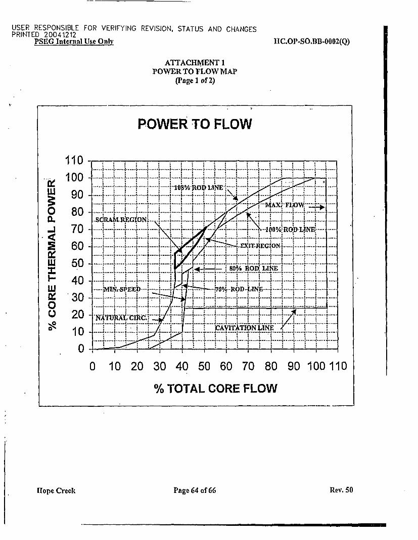
USER RESPONSIBLE FOR VERIFYING REVISION, STATUS AND CHANGESPRINTED 20041212
PSEG Internal Use Only 1IC.OPl-SO.BB-0002(Q)
ATTACHMENT 1POWER TO FLOW MAP
(Page 1 of 2)
POWER TO FLOW
110
0.
-J2
wQ
w
w00X
10090
80706050403020100
-- r . ....- L-j ----I... .... 1. .... . ....... ....----- .----- ... ...... :- ....r . ............. ... . _ . ..
.......... :..... .... :-kW f~ :N :...:..:: .. ::..:.* -: _S.
; j''''''''''-..''''.....j........... ;..... ........ sat6W W ........... ....X--- ! -! - 4...... ... . -... . -....... ... .............. . . ..... .... .... ... . ... ......... ......... ..... ....
.SCRAM-REGION-- .................................... ..... ........... :.:..... _....... ....
............ ;XIT REGION ,. . ... ; : : , ;;j. . s s; + --- -. - -i :-;. . . - -- -. -i --
.... .. . . .... . ... .::.: 4 . : .:.:i i i 'i i i - 80%. ItOf LI*4E'iii... . .... 4 : ......... . .... ....
iMIN. SPEED ..... 0% ROD--- ...................................;
.... ~~~~~~ [o4 ....--- - -: -. 4-s- ,-
I 411-11
i . ii- CAViTAiTIo-N LNC V i. iT
.. ............ . .. .. ............... .. .... ..-. *--.... 'i : i : i _ : @ : i f....i.:..: . :.
0 10 20 30 40 50 60 70 80 90 100 110
% TOTAL CORE FLOW
[lope Creek Page 64 of 66 Rev. 50
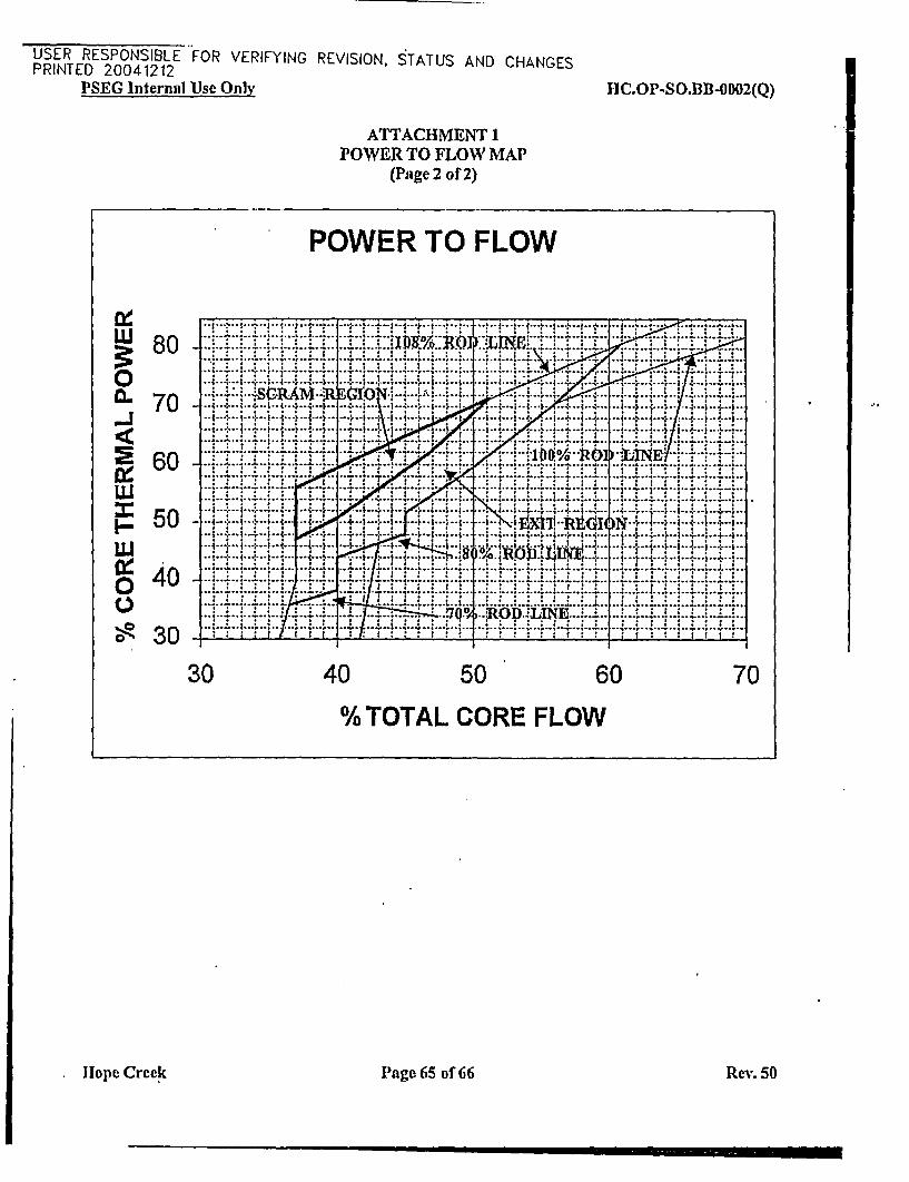
USER RESPONSIBLE FOR VERIFYING REVISION, STATUS AND CHANGESPRINTED 20041212
PSEG Internal 'Use Only HC.OP-SO.B1B-0002(Q)
ATTACHMENT 1POWER TO FLOW MAP
(Page 2 of 2)
POWER TO FLOW
80...... : .. :i:. ... . . . . ::o ..................................-r i .; . ...............
.-. ........ ...... .. ..... . ..................... .iIL60 a..:. .... ...... -* ---.j. .. 14.. .4... -. 4 4 -- .- i.. 1 . 4 .,Jim.. 50 -i. ... ...... ........i 4
60 4 .yq: -. '.' .4.- ? ..? 4 .. .:-... ............. .-..- .j . - .-.:r ... :.-.'.--'.. ... :... , .. f.. 4....... .. .. ... .. .......
4 -...................
C 4....
30 0 50.. ;..qv '607
%TOTL CORE FjL4-4-W--4--4--
-*j^ .3... _ .. ..... .. .. . , f .. s ,1^'...... ::*U -~~~~~~~~~..._i.L..i........... .L .... I - . .9 . .......... '''i'3LIL.. _.' i.i.,,40 , : ::,_1 .,¢,, ,,:: : : ::: : ::::]': '.''
w w , r ; r a. , s.Q~v . RD........ ... ...... ........... 'E. V. '' ... '... .^ ..@s**@... . r..::z.* . .....:..:..... ...:*:*...:..:...:......'....:-.......--..I. .. ,,_,:..,.,,-...~. . ... _ .. . ..
30 40 50 60 70
% TOTAL CORE FLOW
.. ,
11ope Creek Page 65 of 66 Rev. 50
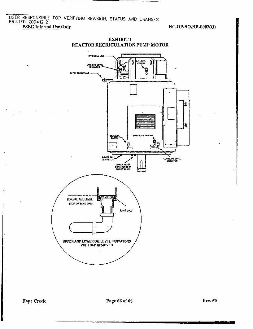
USER RESPONSIBLE FOR VERIFYING REVISION, STATUS AND CHANGESPRINTED 20041212
PSEG Internal Use Only HC.OP-SO.BB-0002(Q)
EXHIBIT 1REACTOR RECRICULATION PUMP MOTOR
WPER OLLIUS
LvOROxL m SV 0Pf ICA TO)R .
PPEi~ DfAIJ VALVC u ett
I.
IU
H-ope Creek Page 66 of 66 Rev. 50


![Compact ink recirculation system CC1 - Toshiba Tec Top Page...Compact ink recirculation system Example: Mounting of ink recirculation system [CC1] with ink recirculation head Up to](https://img.pdfslide.us/doc/110x75/5f0f72527e708231d4443441/compact-ink-recirculation-system-cc1-toshiba-tec-top-page-compact-ink-recirculation.jpg)