Embed Size (px)
Citation preview
HCL Dynamic Spiking Protocol
ELI LILLY AND COMPANY TIPPECANOE LABORATORIES
LAFAYETTE, IN
August, 2006 Revision 2.0
HCL Dynamic Spiking Protocol August, 2006
1
TABLE OF CONTENTS
1 REVISION HISTORY............................................................................................................. 2
1.1 REVISION 1.0 ................................................................................................................. 2 1.2 REVISION 2.0 ................................................................................................................. 2
2 OVERVIEW ........................................................................................................................... 3
3 DEFINITIONS ........................................................................................................................ 5
4 EQUIPMENT ......................................................................................................................... 7
5 EQUIPMENT CALIBRATION AND STANDARDS ................................................................ 8
5.1 HCL CEMS...................................................................................................................... 8 5.2 ELEMENT OF OPPORTUNITY CEMS........................................................................... 8 5.3 FLOW MEASUREMENT SYSTEM................................................................................. 8
5.3.1 Laminar flow element ...................................................................................... 8 5.3.2 Flow by dilution................................................................................................ 9
5.4 GAS MANIFOLD ............................................................................................................. 9 5.5 HCL CALIBRATION GAS FOR DYNAMIC SPIKING ..................................................... 9
6 DYNAMIC SPIKING RANGE............................................................................................... 10
7 TYPICAL DYNAMIC SPIKING SET-UP .............................................................................. 10
8 DYNAMIC SPIKING PROCEDURE .................................................................................... 11
8.1 COLLECTION OF BASELINE DATA............................................................................ 11 8.2 COLLECTION OF TEST DATA .................................................................................... 11 8.3 DATA CALCULATIONS................................................................................................ 12
8.3.1 Baseline data................................................................................................. 12 8.3.2 Dynamic Spiking Test run data ..................................................................... 14 8.3.3 Reference HCL concentration calculations ................................................... 15 8.3.4 Linear Regression ......................................................................................... 16
8.4 CRITERIA FOR ACCEPTANCE ................................................................................... 17 8.5 BIAS CORRECTION..................................................................................................... 18
9 TABLES ............................................................................................................................... 19
10 REFERENCES .................................................................................................................... 20
11 APPENDIXES...................................................................................................................... 21
HCL Dynamic Spiking Protocol August, 2006
2
1 REVISION HISTORY
1.1 REVISION 1.0
Revision 1.0, Tippecanoe Laboratories NON-GMP Standard Operating Procedure, Eli Lilly and Company,
December 18, 2005.
1.2 REVISION 2.0
This revision is an update of the original Dynamic Spiking protocol, December 2005. The following are
key updates in revision 2.0:
1. Recommendation that all HCL QA gases be certified with a minimum tolerance of 5%
2. Discussion for the use of quantitative introduction of the HCL calibration gas and subsequent total
flow measurement as method for determining the reference HCL concentration during each test
run.
3. Updated the dynamic spiking procedure description for easier flow of information
4. Updated the equations to include percent relative standard deviation and the calculation for the
reference HCL concentration when using quantitative introduction of the HCL calibration gas with
subsequent total flow measurement.
HCL Dynamic Spiking Protocol August, 2006
3
2 OVERVIEW
Dynamic Spiking is procedure to establish the accuracy, precision, and bias of a monitoring system. During the dynamic spiking procedure, a certified calibration gas (+/- 5%) is spiked into the monitoring system while the system is sampling flue gas. It is important that the spiked calibration gas flow through the entire sampling system. The target ratio of flue gas to HCL calibration gas is 9:1, with a minimum requirement of 1:1. The HCL calibration gas is spiked in three ranges (low, mid, high) through the range of HCL detector. A minimum of 30, one minute averaged data points should be collected for each of the three test runs. It is recommended that the percent relative standard deviation of the data set, for each test level, be less than or equal to 20%.
If the flue gas has significant amounts of HCL present, the data may be corrected for the baseline HCL concentration. This is performed by collecting at least 10, one minute average HCL data points prior to each test run. The average of the ten baseline HCL values will be used to compensate the subsequent test run data for background HCL concentrations. It is important that the control device be running at steady state; alleviating large fluctuations in the background HCL concentrations.
The HCL CEMS will provide the measured HCL values. These values are compared, using linear regression, to the known or spiked HCL concentrations. There are two methods for calculating the known HCL concentrations: (1) Use of an element of opportunity and (2) Quantitative introduction of the HCL calibration gas with total flow through the system.
An element of opportunity can be any element normally present, in steady concentrations, in the flue gas stream. Examples are O2, CO, NOx, SO2, CO2, and moisture. Total flow through the system is also an example of an element of opportunity.
The element of opportunity is measured during the baseline data collection, prior to the test run. The average value during this baseline collection period is used to establish the baseline concentration, or flow value, without any spiking of the calibration gas.
The element of opportunity is measured during each test run while the HCL calibration gas is being spiked. The elements of opportunity values, collected during each test run are averaged. Knowing the concentration of the HCL calibration gas, and the dilution of the element of opportunity due to the spiking, the known value of the HCL calibration gas in the measurement stream can be calculated.
The known value of the spiked HCL calibration gas in the measurement stream can also be calculated by quantitatively introducing the HCL calibration gas, and, measuring the total flow through the system. In this case, the HCL calibration gas concentration, the flow rate of spiked HCL calibration gas into the measurement stream, and the total flow through the system are used to calculate the known value of the spiked calibration gas.
As with the HCL CEMS data sets, it is recommended that the percent relative standard deviation for the element of opportunity data sets be less than or equal to 20%.
Once the data is collected, linear regression is performed using the known HCL spike values and the correlating HCL CEMS measured values. Criteria for the HCL dynamic spiking are:
1. The correlation coefficient ® must be greater than or equal to 0.90.
2. the slope of the regression line must be 1.0 +/- 0.15.
HCL Dynamic Spiking Protocol August, 2006
4
3. The intercept, of the regression line, must be less than or equal to 15% of the instrument span.
The HCL CEMS must meet the correlation criteria. If either the slope and/or intercept criteria are not met, a bias may be applied to the HCL CEMS one minute value. Performance Specification Z: Specifications and Test Procedures for the HCL Continuous Emission Monitoring Systems at Stationary Sources should be as a reference document for dynamic spiking requirements and calculations.
HCL Dynamic Spiking Protocol August, 2006
5
3 DEFINITIONS
Bias: The difference between the reference value and the measured value.
Calibration Drift: The difference in the CEMS output readings from the established reference value after
a stated period of operation during which no unscheduled maintenance or adjustment took place.
Continuous Emission Monitoring System: means the total equipment required for the determination of
a gas concentration or emission rate. The sample interface, pollutant analyzer, diluent analyzer, and data
recorder are the major subsystems of the CEMS.
Correlation Coefficient: determines the extent of a linear relationship between two fields over a given
period of time.
Data Recorder: The portion of the CEMS that provides a record of analyzer output, flags which indicate
normal operation, and flags indicating abnormal operation. The data recorder may record other pertinent
data such as effluent flow rates, and various instrument temperatures.
Dynamic Spiking: a procedure used to document the accuracy, precision, and bias of the monitoring
system by quantitatively spiking a certified gas into the pollutant gas stream.
Element of Opportunity: Any element, present in the flue gas matrix (or total flow) that has little
fluctuation and can be used to determine the reference HCL concentration during the dynamic spiking
test runs.
Gas Chromatograph: An analytical instrument which uses a carrier gas to transport gas/vapor phase
samples to a solid matrix for separation, and subsequent detection by a analyte specific detector.
Gas manifold: Individual, or series of flow controllers that allow controlled flow of a gas. Calibrated flow
controllers can be used to quantitatively control the flow of gases.
HCL Dynamic Spiking Protocol August, 2006
6
Instrument Measurement Range: The range of HCl concentrations the instrument can reliably measure
from the lowest concentration to the highest.
Intercept: value of the Y variable when the X variable is equal to zero.
Laminar Flow Element: A device used to measure the flow gas through a system by measuring the
pressure drop of the gas over a restriction (forces parallel, or laminar flow).
Linear Regression: a methodology used to find a formula that can be used to relate two variables that
are linearly related.
Response Time: The time interval between the start of a step change in the system input and when the
pollutant analyzer output reached 95% of the final value.
Sample Interface: The portion of the CEMS used for one or more of the following: sample acquisition,
sample transport, sample conditioning, or protection of the monitor from the effects of stack gas.
Slope: The rate of change of Y relative to the change in X.
Upscale drift: means the absolute difference between a high-level calibration gas and the monitor
response, in units of the applicable standard.
Zero drift: means the absolute difference between a high-level calibration gas and the monitor response,
in units of the applicable standard.
HCL Dynamic Spiking Protocol August, 2006
7
4 EQUIPMENT
The following list contains typical equipment required to perform the HCL dynamic spiking.
1. HCL CEMS
2. Reference Analyzer(s) for the element of opportunity (examples are NOx, SO2, CO, CO2, O2)
3. Flow Measurement Systems
a. Laminar flow element
b. Gas chromatograph (for dilution flow with a hydrocarbon)
4. Calibration Equipment
a. Bubble Flow meter, manometer, or equivalent for primary flow calibration
b. Certified HCL Calibration gas for spiking
c. HCL calibration gases for zero and upscale drift check of the HCL CEMS
d. Calibration gas for the element(s) of opportunity CEMS calibration
e. Hydrocarbon gas for flow measurement via dilution sampling
5. Quantitative gas manifold, or equivalent, for introduction of the HCL calibration gas
6. Quantitative gas manifold, or equivalent, for the introduction of the hydrocarbon for dilution flow (if
used)
7. Various fittings and tubing
HCL Dynamic Spiking Protocol August, 2006
8
5 EQUIPMENT CALIBRATION AND STANDARDS
Prior to performing the HCL dynamic spiking, it is important that all equipment and/or analyzers are
calibrated. This section provides guidance on the calibration requirements for all equipment used during
the HCL dynamic spiking procedure.
5.1 HCL CEMS
Prior to performing the dynamic spiking procedure, the HCL CEMS must pass the QA requirements
specified in performance specification Z: Specifications and Test Procedures For HCL Continuous
Emission Monitoring Systems at Stationary Sources. Typically, this would include passing the daily zero
and upscale calibration drift check, and for annual audits passing both the zero and upscale drift check as
well as a seven day drift test. All calibration gases must be certified gases, with a recommended
tolerance not to exceed +/- 5%.
5.2 ELEMENT OF OPPORTUNITY CEMS
The monitoring system used to measure the element(s) of opportunity, other than total flow, must pass a
calibration directly prior to use. After dynamic spiking run, the zero and upscale calibration drift are
checked. The drift requirement, for both zero and upscale, is 3% of the reference value, unless stated
otherwise in the applicable reference method. If either the zero or upscale calibration check fails the drift
limit after a dynamic spiking run, the run must be repeated.
5.3 FLOW MEASUREMENT SYSTEM
Total flow may be used as an element of opportunity, or, as part of measuring the quantitative
introduction of the HCL calibration gas for the dynamic spiking tests. There are several methods that can
be used to provide a total flow measurement. This protocol outlines two approaches, laminar flow
element and flow by dilution. Other total flow measurement systems can be used; however, specific
protocol describing the methodology must be used.
5.3.1 Laminar flow element
Prior to the dynamic spiking procedure, the laminar flow element is calibrated against a primary flow
standard, such as a bubble flow meter. The calibration must include at least three points throughout the
expected measurement range. After each dynamic spiking test run, the calibration drift is checked at
each of the three points. The laminar flow element must be re-calibrated if any of the drift check points
exceed 10% of the expected value (established during the pre-test calibration).
HCL Dynamic Spiking Protocol August, 2006
9
5.3.2 Flow by dilution
Flow by dilution is a method where a known concentration of gas is quantitatively introduced to the flue
gas stream and measured downstream by a calibrated instrument. For example, a known concentration
of propane can be quantitatively introduced to the flue gas stream and the diluted propane measured
downstream.
Prior to the dynamic spiking procedure, the gas chromatograph is calibrated, using at least four points
through the expected measurement range. After the dynamic spiking procedure is complete, the gas
chromatograph is checked for bias at each of the four calibration levels. The bias should be less than 5%
of the expected value for each point. Method 18 provides guidance for the calibration procedure and
requirements.
Prior to the dynamic spiking procedure, the gas manifold (used to quantitatively introduce propane, or
similar hydrocarbon), which is typically a mass flow controller, is calibrated to a primary standard. After
each test run, the gas manifold is checked for drift, and adjusted if the drift exceeds 10% of the expected
value (calibrated value prior to dynamic spiking procedure). Method 205 provides guidance for this
procedure.
5.4 GAS MANIFOLD
HCL may be quantitatively introduced into the flue gas stream, and when used in conjunction with a total
flow measurement, can provide the reference HCL spiking concentrations for each dynamic spiking run.
Prior to the dynamic spiking procedure, the gas manifold (used to quantitatively introduce HCL), which is
typically a mass flow controller, is calibrated to a primary standard. After each test run, the gas manifold
is checked for drift, and adjusted if the drift exceeds 10% of the expected value (calibrated value prior to
dynamic spiking procedure). Method 205 provides guidance for this procedure.
5.5 HCL CALIBRATION GAS FOR DYNAMIC SPIKING
The HCL calibration gas used for dynamic spiking must be a certified gas with a tolerance less than or
equal to 5%.
HCL Dynamic Spiking Protocol August, 2006
10
6 DYNAMIC SPIKING RANGE
The flue gas stream must be spiked at a minimum of three separate levels (low, mid, high) throughout the
range of the HCL CEMS. The low level should be between 0 – 50%, the mid range should be between
25 – 75%, and the high range should be between 50 – 100% of the span of the instrument. The dynamic
spiked HCL concentrations can only be used for one range (Table 1).
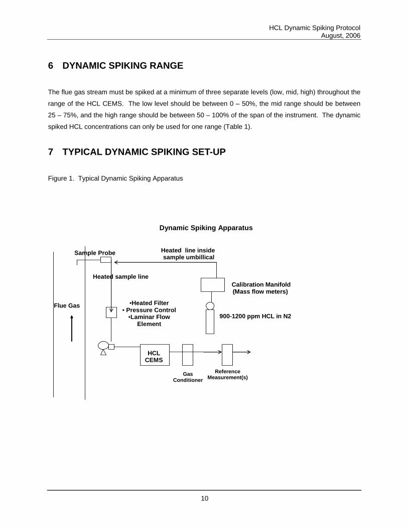
7 TYPICAL DYNAMIC SPIKING SET-UP
Figure 1. Typical Dynamic Spiking Apparatus
Dynamic Spiking Apparatus
HCL CEMS
900-1200 ppm HCL in N2
Calibration Manifold(Mass flow meters)
Sample Probe
•Heated Filter • Pressure Control
•Laminar Flow Element
Heated sample line
Flue Gas
GasConditioner
ReferenceMeasurement(s)
Heated line inside sample umbillical
HCL Dynamic Spiking Protocol August, 2006
11
8 DYNAMIC SPIKING PROCEDURE
This section describes the procedure used to perform HCL dynamic spiking. Prior to testing, it is
important that all analyzers are calibrated according to section 6 of this document. In addition, the control
device should be at a steady state (small fluctuations of HCL or elements of opportunity).
8.1 COLLECTION OF BASELINE DATA
The baseline data will be used to compensate the measured HCl, during the dynamic spiking run, for
background concentrations of HCL which may be present during normal operations. It is important to
collect all element of opportunity data as well as HCL background data during the baseline collection
period.
1. Collect a minimum of ten, 1 minute averaged HCL data points prior to each dynamic spiking
test run.
2. Collect ten, 1 minute averaged data points for the element(s) of opportunity to be used for
calculating the reference HCL concentration. The element of opportunity data set is collected
simultaneous to the HCL baseline data, and must be collected prior to each dynamic spiking
test run.
3. If using total flow, collect a minimum of one flow reading during the baseline data collection.
4. Prior to beginning the dynamic spike, ensure that all baseline data (HCL, element of
opportunity, flow) does not exhibit large fluctuations in concentration (steady state). If large
fluctuations exist, the baseline data collection procedure must be repeated.
8.2 COLLECTION OF TEST DATA
The HCL CEMS must be tested at a minimum of three levels through the measurement range of the
instrument (low, mid, high), Table 1. Prior to each dynamic spiking test run, it is important that the
appropriate baseline data is collected (section 7.1) and that all equipment is calibrated and appropriate
bias checks are performed (section 6).
1. Introduce the HCL calibration gas to the measurement system and allow the HCL CEMS
values to reach a steady state. This may take up to 15 minutes.
HCL Dynamic Spiking Protocol August, 2006
12
2. Collect a minimum of 30, one minute average HCL data points.
3. Collect a minimum of 30, one minute average element(s) of opportunity data points.
4. If using total flow through the system, collect at least five data points during the dynamic
spiking test run.
5. If using quantitative introduction of the HCL calibration gas, collect at least five data points for
the calibration gas flow rate into the system during the dynamic spiking test run.
6. Before stopping the dynamic spiking test run, ensure that the data sets are complete. It is
recommended that the percent standard deviation, for all data sets, be less than or equal to
20%.
7. Stop the HCL calibration gas dynamic spiking and allow the system to return to baseline
conditions.
8. Perform a bias check for the element of opportunity reference CEMS, the flow measurement
system, and the gas manifold for the HCL calibration gas and hydrocarbon (if dilution flow is
used to calculate the reference HCL concentration). Section 6 provides guidance for the bias
checks.
9. Repeat the baseline data collection, and the dynamic spiking data collection, for subsequent
HCL test levels.
10. If dilution flow is used to calculate the HCl reference values, after the HCL dynamic spiking
test runs are complete, perform a bias check of the dilution analyzer.
8.3 DATA CALCULATIONS
This section provides the calculations required to determine the accuracy, precision, and bias of the HCL
CEMS.
8.3.1 Baseline data
8.3.1.1 HCL CEMS data
The baseline HCL concentration is measured prior to each dynamic spiking run. For each baseline HCL
data set, calculate the average, in ppm, using equation 1.
HCL Dynamic Spiking Protocol August, 2006
13
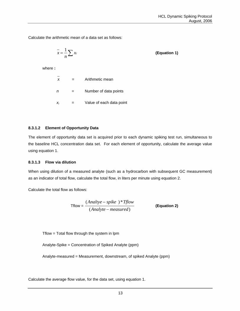
Calculate the arithmetic mean of a data set as follows:
∑= ixn
x 1 (Equation 1)
where :
x = Arithmetic mean
n = Number of data points
xi = Value of each data point
8.3.1.2 Element of Opportunity Data
The element of opportunity data set is acquired prior to each dynamic spiking test run, simultaneous to
the baseline HCL concentration data set. For each element of opportunity, calculate the average value
using equation 1.
8.3.1.3 Flow via dilution
When using dilution of a measured analyte (such as a hydrocarbon with subsequent GC measurement)
as an indicator of total flow, calculate the total flow, in liters per minute using equation 2.
Calculate the total flow as follows:
Tflow = )(
*)(measuredAnalyte
TflowspikeAnaltye−
− (Equation 2)
Tflow = Total flow through the system in lpm
Analyte-Spike = Concentration of Spiked Analyte (ppm)
Analyte-measured = Measurement, downstream, of spiked Analyte (ppm)
Calculate the average flow value, for the data set, using equation 1.
HCL Dynamic Spiking Protocol August, 2006
14
8.3.2 Dynamic Spiking Test run data
8.3.2.1 HCL CEMS data
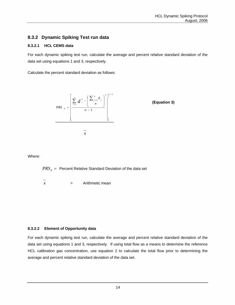
For each dynamic spiking test run, calculate the average and percent relative standard deviation of the
data set using equations 1 and 3, respectively.
Calculate the percent standard deviation as follows:
2/12
1
1
2
1
⎥⎥⎥⎥⎥⎥⎥
⎦
⎤
⎢⎢⎢⎢⎢⎢⎢
⎣
⎡
−
⎟⎟
⎠
⎞
⎜⎜
⎝
⎛−
=
∑∑ =
=
n
nd
PRS
n
i in
ii
d
d (Equation 3)
x
Where:
=dPRS Percent Relative Standard Deviation of the data set
x = Arithmetic mean
8.3.2.2 Element of Opportunity data
For each dynamic spiking test run, calculate the average and percent relative standard deviation of the
data set using equations 1 and 3, respectively. If using total flow as a means to determine the reference
HCL calibration gas concentration, use equation 2 to calculate the total flow prior to determining the
average and percent relative standard deviation of the data set.
HCL Dynamic Spiking Protocol August, 2006
15
8.3.3 Reference HCL concentration calculations
8.3.3.1 Element of opportunity to calculate reference HCL concentration
Equation 4 is used to calculate the reference HCL concentration for a given dynamic spiking test run.
HCl ref = lBaselineHCCalGaspreOpppostOpp
avg
avg +−
−− *1 (Equation 4)
where:
Opp-post avg = average reference element of opportunity value during dynamic spiking test run
Opp-pre avg = average reference element of opportunity value during baseline test run
CalGas = HCl calibration gas concentration
Baseline HCl = CEMS HCl average baseline value
8.3.3.2 Quantitative HCL calibration gas introduction and total flow to calculate reference HCL concentration
When using the quantitative introduction of calibration gas and total system flow to calculation the
reference HCL concentration for a given dynamic spiking test run, use equation 5. Equation 2 is used to
calculate the total system flow.
HCl ref = lBaselineHCCalGasTflowCflow
avg
avg +* (Equation 5)
Where:
HCl ref = Reference HCl value for run “X”
Cflow = Average calibration HCL gas flow rate into system (lpm)
HCL Dynamic Spiking Protocol August, 2006
16
Tflow = Average Total System Flow during run (lpm)
CalGas = HCl calibration gas concentration
Baseline HCl = CEMS HCl average baseline value
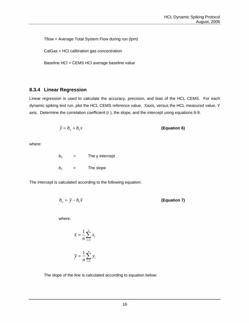
8.3.4 Linear Regression
Linear regression is used to calculate the accuracy, precision, and bias of the HCL CEMS. For each
dynamic spiking test run, plot the HCL CEMS reference value, Xaxis, versus the HCL measured value, Y
axis. Determine the correlation coefficient (r ), the slope, and the intercept using equations 6-9.
xbby o 1ˆ += (Equation 6)
where:
bo = The y intercept
b1 = The slope
The intercept is calculated according to the following equation:
xbybo 1−= (Equation 7)
where:
∑=
=n
iix
nx
1
1
∑=
=n
iiy
ny
1
1
The slope of the line is calculated according to equation below:
HCL Dynamic Spiking Protocol August, 2006
17
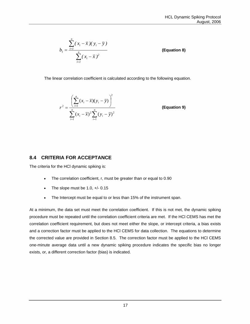
∑
∑
=
=
−
−−= n
1i
2i
n
1iii
1
)xx(
)yy)(xx(b (Equation 8)
The linear correlation coefficient is calculated according to the following equation.
∑∑
∑
==
=
−−
⎟⎠
⎞⎜⎝
⎛−−
= n
ii
n
ii
n
iii
yyxx
yyxxr
1
2
1
2
2
12
)()(
))(( (Equation 9)
8.4 CRITERIA FOR ACCEPTANCE
The criteria for the HCl dynamic spiking is:
• The correlation coefficient, r, must be greater than or equal to 0.90
• The slope must be 1.0, +/- 0.15
• The Intercept must be equal to or less than 15% of the instrument span.
At a minimum, the data set must meet the correlation coefficient. If this is not met, the dynamic spiking
procedure must be repeated until the correlation coefficient criteria are met. If the HCl CEMS has met the
correlation coefficient requirement, but does not meet either the slope, or intercept criteria, a bias exists
and a correction factor must be applied to the HCl CEMS for data collection. The equations to determine
the corrected value are provided in Section 8.5. The correction factor must be applied to the HCl CEMS
one-minute average data until a new dynamic spiking procedure indicates the specific bias no longer
exists, or, a different correction factor (bias) is indicated.
HCL Dynamic Spiking Protocol August, 2006
18
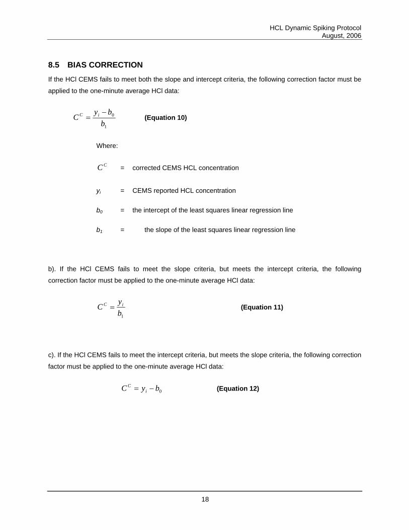
8.5 BIAS CORRECTION
If the HCl CEMS fails to meet both the slope and intercept criteria, the following correction factor must be
applied to the one-minute average HCl data:
1
0
bby
C iC −= (Equation 10)
Where:
CC = corrected CEMS HCL concentration
yi = CEMS reported HCL concentration
b0 = the intercept of the least squares linear regression line
b1 = the slope of the least squares linear regression line
b). If the HCl CEMS fails to meet the slope criteria, but meets the intercept criteria, the following
correction factor must be applied to the one-minute average HCl data:
1by
C iC = (Equation 11)
c). If the HCl CEMS fails to meet the intercept criteria, but meets the slope criteria, the following correction
factor must be applied to the one-minute average HCl data:
0byC iC −= (Equation 12)
HCL Dynamic Spiking Protocol August, 2006
19
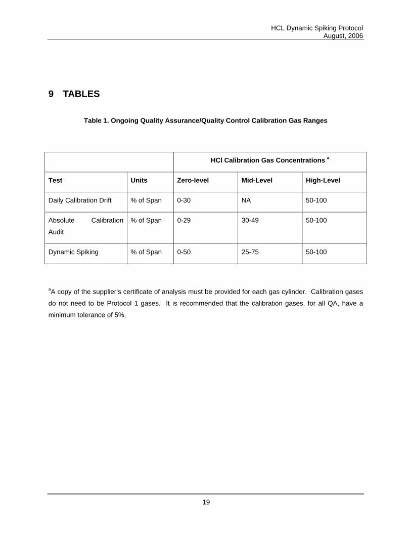
9 TABLES
Table 1. Ongoing Quality Assurance/Quality Control Calibration Gas Ranges
HCl Calibration Gas Concentrations a
Test Units Zero-level Mid-Level High-Level
Daily Calibration Drift % of Span 0-30 NA 50-100
Absolute Calibration
Audit
% of Span 0-29 30-49 50-100
Dynamic Spiking % of Span 0-50 25-75 50-100
aA copy of the supplier’s certificate of analysis must be provided for each gas cylinder. Calibration gases
do not need to be Protocol 1 gases. It is recommended that the calibration gases, for all QA, have a
minimum tolerance of 5%.
HCL Dynamic Spiking Protocol August, 2006
20
10 REFERENCES
1. United States Environmental Protection Agency (EPA). Technology Transfer Network, Emission
Measurement Center, Promulgated Methods, Test Method 205: Verification of Gas Dilution
Systems for Field Instrument Calibrations. Available: http://www.epa.gov/ttn/emc/promgate/m-
205.pdf via the internet.
2. United States Environmental Protection Agency (EPA). Technology Transfer Network, Emission
Measurement Center, Promulgated Methods, Test Method 18: Measurement of Gaseous
Organic Compound Emissions by Gas Chromatography. Available:
http://www.epa.gov/ttn/emc/promgate/m-18.pdf via the internet.
3. Performance Specification Z: Specifications and Test Procedures for Hydrochloric Acid
Continuous Emission Monitoring Systems at Stationary Sources. Eli Lilly and Company, 2005.
4. Procedure DD: Quality Control and Quality Assurance Requirements for Hydrochloric Acid
Continuous Emission Monitoring Systems at Stationary Sources. Eli Lilly and Company, 2005.
5. Dilution Flow Measurement Protocol: Measurement of Total flow using a tracer gas with
subsequent down stream quantitation. Eli Lilly and Company, 2006.
HCL Dynamic Spiking Protocol August, 2006
21
11 APPENDICES