Embed Size (px)
Citation preview
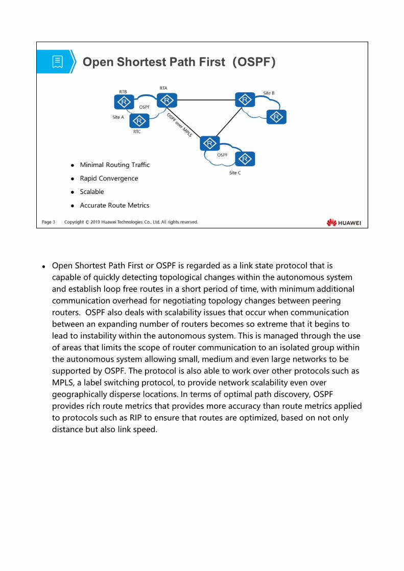
Open Shortest Path First or OSPF is regarded as a link state protocol that is capable of quickly detecting topological changes within the autonomous system and establish loop free routes in a short period of time, with minimum additional communication overhead for negotiating topology changes between peering routers. OSPF also deals with scalability issues that occur when communication between an expanding number of routers becomes so extreme that it begins to lead to instability within the autonomous system. This is managed through the use of areas that limits the scope of router communication to an isolated group within the autonomous system allowing small, medium and even large networks to be supported by OSPF. The protocol is also able to work over other protocols such as MPLS, a label switching protocol, to provide network scalability even over geographically disperse locations. In terms of optimal path discovery, OSPF provides rich route metrics that provides more accuracy than route metrics applied to protocols such as RIP to ensure that routes are optimized, based on not only distance but also link speed.
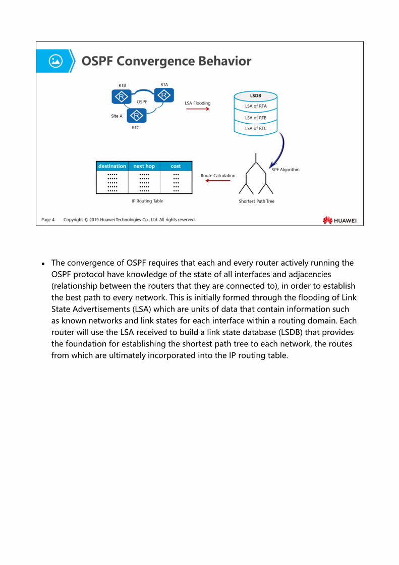
The convergence of OSPF requires that each and every router actively running the OSPF protocol have knowledge of the state of all interfaces and adjacencies (relationship between the routers that they are connected to), in order to establish the best path to every network. This is initially formed through the flooding of Link State Advertisements (LSA) which are units of data that contain information such as known networks and link states for each interface within a routing domain. Each router will use the LSA received to build a link state database (LSDB) that provides the foundation for establishing the shortest path tree to each network, the routes from which are ultimately incorporated into the IP routing table.
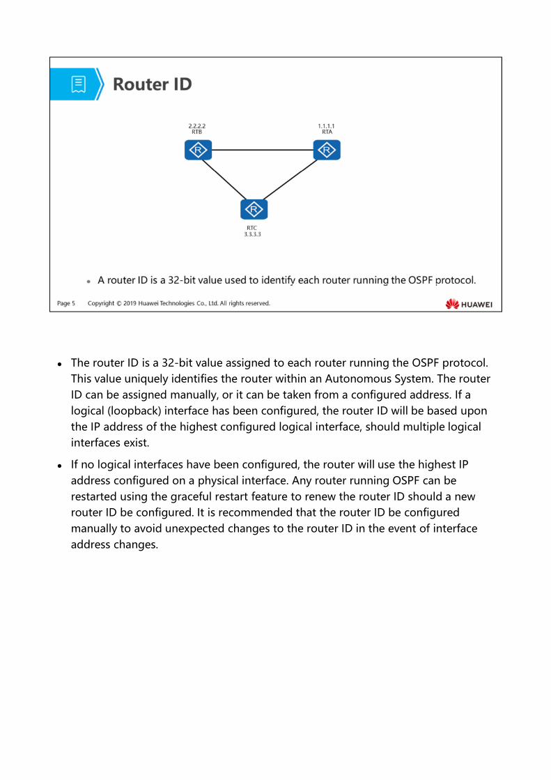
The router ID is a 32-bit value assigned to each router running the OSPF protocol. This value uniquely identifies the router within an Autonomous System. The router ID can be assigned manually, or it can be taken from a configured address. If a logical (loopback) interface has been configured, the router ID will be based upon the IP address of the highest configured logical interface, should multiple logical interfaces exist.
If no logical interfaces have been configured, the router will use the highest IP address configured on a physical interface. Any router running OSPF can be restarted using the graceful restart feature to renew the router ID should a new router ID be configured. It is recommended that the router ID be configured manually to avoid unexpected changes to the router ID in the event of interface address changes.
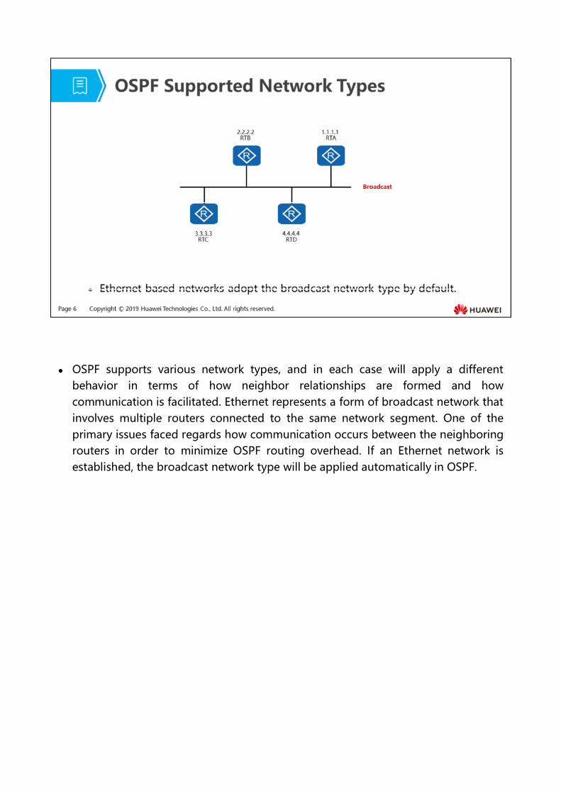
OSPF supports various network types, and in each case will apply a differentbehavior in terms of how neighbor relationships are formed and howcommunication is facilitated. Ethernet represents a form of broadcast network thatinvolves multiple routers connected to the same network segment. One of theprimary issues faced regards how communication occurs between the neighboringrouters in order to minimize OSPF routing overhead. If an Ethernet network isestablished, the broadcast network type will be applied automatically in OSPF.
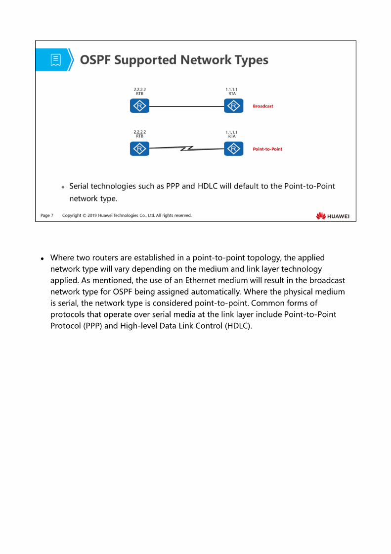
Where two routers are established in a point-to-point topology, the applied network type will vary depending on the medium and link layer technology applied. As mentioned, the use of an Ethernet medium will result in the broadcast network type for OSPF being assigned automatically. Where the physical medium is serial, the network type is considered point-to-point. Common forms of protocols that operate over serial media at the link layer include Point-to-Point Protocol (PPP) and High-level Data Link Control (HDLC).
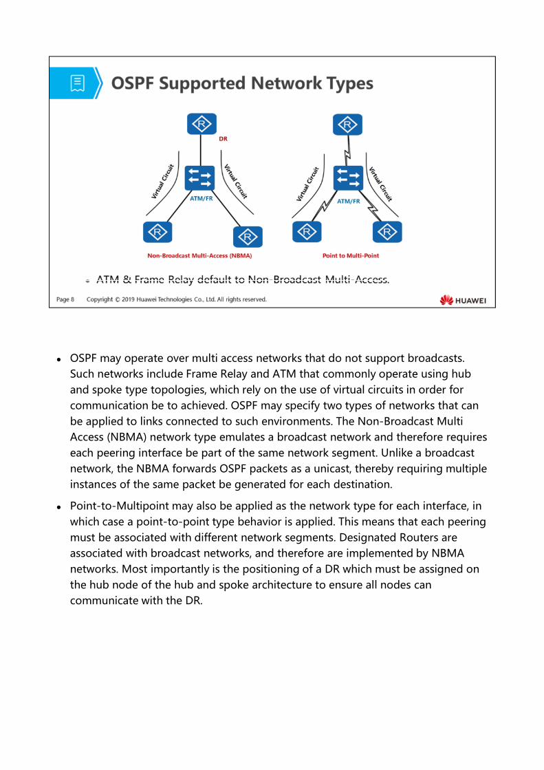
OSPF may operate over multi access networks that do not support broadcasts. Such networks include Frame Relay and ATM that commonly operate using hub and spoke type topologies, which rely on the use of virtual circuits in order for communication be to achieved. OSPF may specify two types of networks that can be applied to links connected to such environments. The Non-Broadcast Multi Access (NBMA) network type emulates a broadcast network and therefore requires each peering interface be part of the same network segment. Unlike a broadcast network, the NBMA forwards OSPF packets as a unicast, thereby requiring multiple instances of the same packet be generated for each destination.
Point-to-Multipoint may also be applied as the network type for each interface, in which case a point-to-point type behavior is applied. This means that each peering must be associated with different network segments. Designated Routers are associated with broadcast networks, and therefore are implemented by NBMA networks. Most importantly is the positioning of a DR which must be assigned on the hub node of the hub and spoke architecture to ensure all nodes can communicate with the DR.
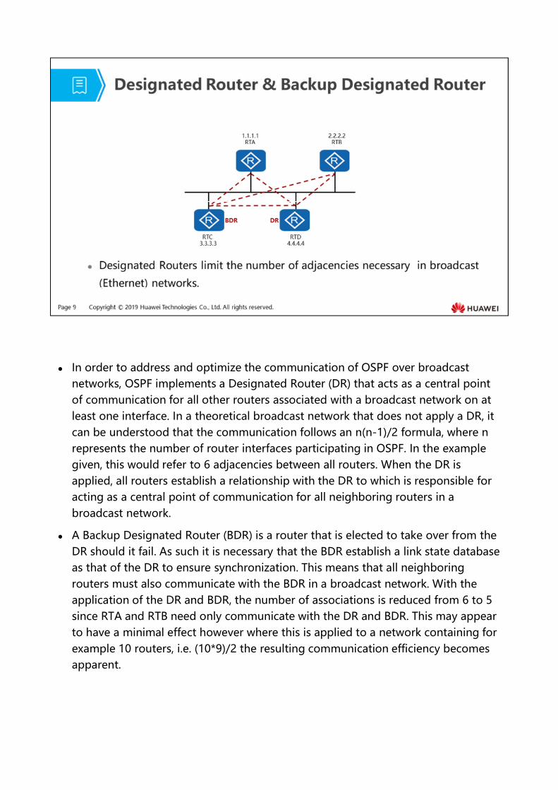
In order to address and optimize the communication of OSPF over broadcast networks, OSPF implements a Designated Router (DR) that acts as a central point of communication for all other routers associated with a broadcast network on at least one interface. In a theoretical broadcast network that does not apply a DR, it can be understood that the communication follows an n(n-1)/2 formula, where n represents the number of router interfaces participating in OSPF. In the example given, this would refer to 6 adjacencies between all routers. When the DR is applied, all routers establish a relationship with the DR to which is responsible for acting as a central point of communication for all neighboring routers in a broadcast network.
A Backup Designated Router (BDR) is a router that is elected to take over from the DR should it fail. As such it is necessary that the BDR establish a link state database as that of the DR to ensure synchronization. This means that all neighboring routers must also communicate with the BDR in a broadcast network. With the application of the DR and BDR, the number of associations is reduced from 6 to 5 since RTA and RTB need only communicate with the DR and BDR. This may appear to have a minimal effect however where this is applied to a network containing for example 10 routers, i.e. (10*9)/2 the resulting communication efficiency becomes apparent.
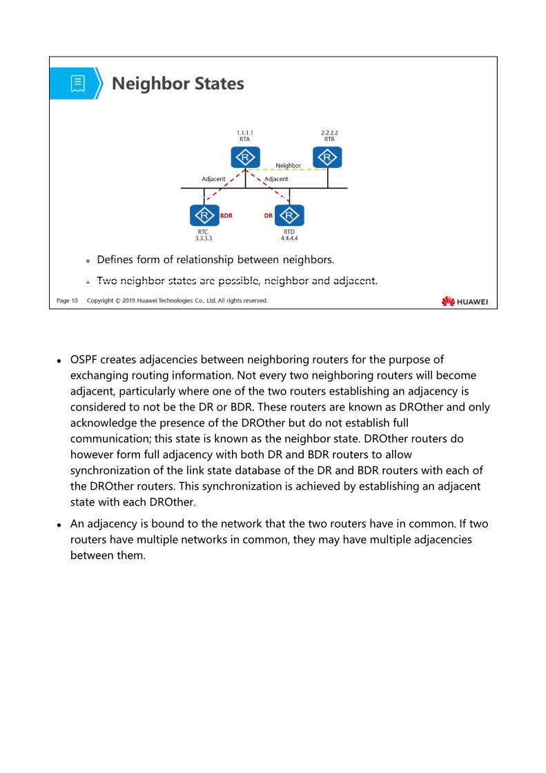
OSPF creates adjacencies between neighboring routers for the purpose of exchanging routing information. Not every two neighboring routers will become adjacent, particularly where one of the two routers establishing an adjacency is considered to not be the DR or BDR. These routers are known as DROther and only acknowledge the presence of the DROther but do not establish full communication; this state is known as the neighbor state. DROther routers do however form full adjacency with both DR and BDR routers to allow synchronization of the link state database of the DR and BDR routers with each of the DROther routers. This synchronization is achieved by establishing an adjacent state with each DROther.
An adjacency is bound to the network that the two routers have in common. If two routers have multiple networks in common, they may have multiple adjacencies between them.
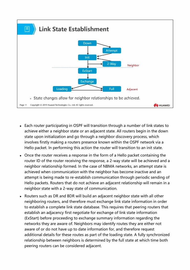
Each router participating in OSPF will transition through a number of link states to achieve either a neighbor state or an adjacent state. All routers begin in the down state upon initialization and go through a neighbor discovery process, which involves firstly making a routers presence known within the OSPF network via a Hello packet. In performing this action the router will transition to an init state.
Once the router receives a response in the form of a Hello packet containing the router ID of the router receiving the response, a 2-way state will be achieved and a neighbor relationship formed. In the case of NBMA networks, an attempt state is achieved when communication with the neighbor has become inactive and an attempt is being made to re-establish communication through periodic sending of Hello packets. Routers that do not achieve an adjacent relationship will remain in a neighbor state with a 2-way state of communication.
Routers such as DR and BDR will build an adjacent neighbor state with all other neighboring routers, and therefore must exchange link state information in order to establish a complete link state database. This requires that peering routers that establish an adjacency first negotiate for exchange of link state information (ExStart) before proceeding to exchange summary information regarding the networks they are aware of. Neighbors may identify routes they are either not aware of or do not have up to date information for, and therefore request additional details for these routes as part of the loading state. A fully synchronized relationship between neighbors is determined by the full state at which time both peering routers can be considered adjacent.
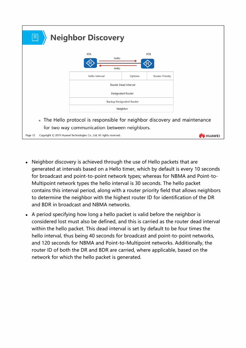
Neighbor discovery is achieved through the use of Hello packets that are generated at intervals based on a Hello timer, which by default is every 10 seconds for broadcast and point-to-point network types; whereas for NBMA and Point-to-Multipoint network types the hello interval is 30 seconds. The hello packet contains this interval period, along with a router priority field that allows neighbors to determine the neighbor with the highest router ID for identification of the DR and BDR in broadcast and NBMA networks.
A period specifying how long a hello packet is valid before the neighbor is considered lost must also be defined, and this is carried as the router dead interval within the hello packet. This dead interval is set by default to be four times the hello interval, thus being 40 seconds for broadcast and point-to-point networks, and 120 seconds for NBMA and Point-to-Multipoint networks. Additionally, the router ID of both the DR and BDR are carried, where applicable, based on the network for which the hello packet is generated.
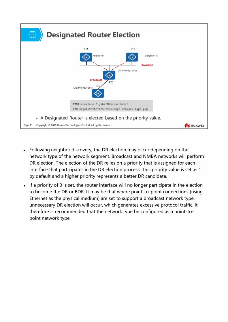
Following neighbor discovery, the DR election may occur depending on the network type of the network segment. Broadcast and NMBA networks will perform DR election. The election of the DR relies on a priority that is assigned for each interface that participates in the DR election process. This priority value is set as 1 by default and a higher priority represents a better DR candidate.
If a priority of 0 is set, the router interface will no longer participate in the election to become the DR or BDR. It may be that where point-to-point connections (using Ethernet as the physical medium) are set to support a broadcast network type, unnecessary DR election will occur, which generates excessive protocol traffic. It therefore is recommended that the network type be configured as a point-to-point network type.
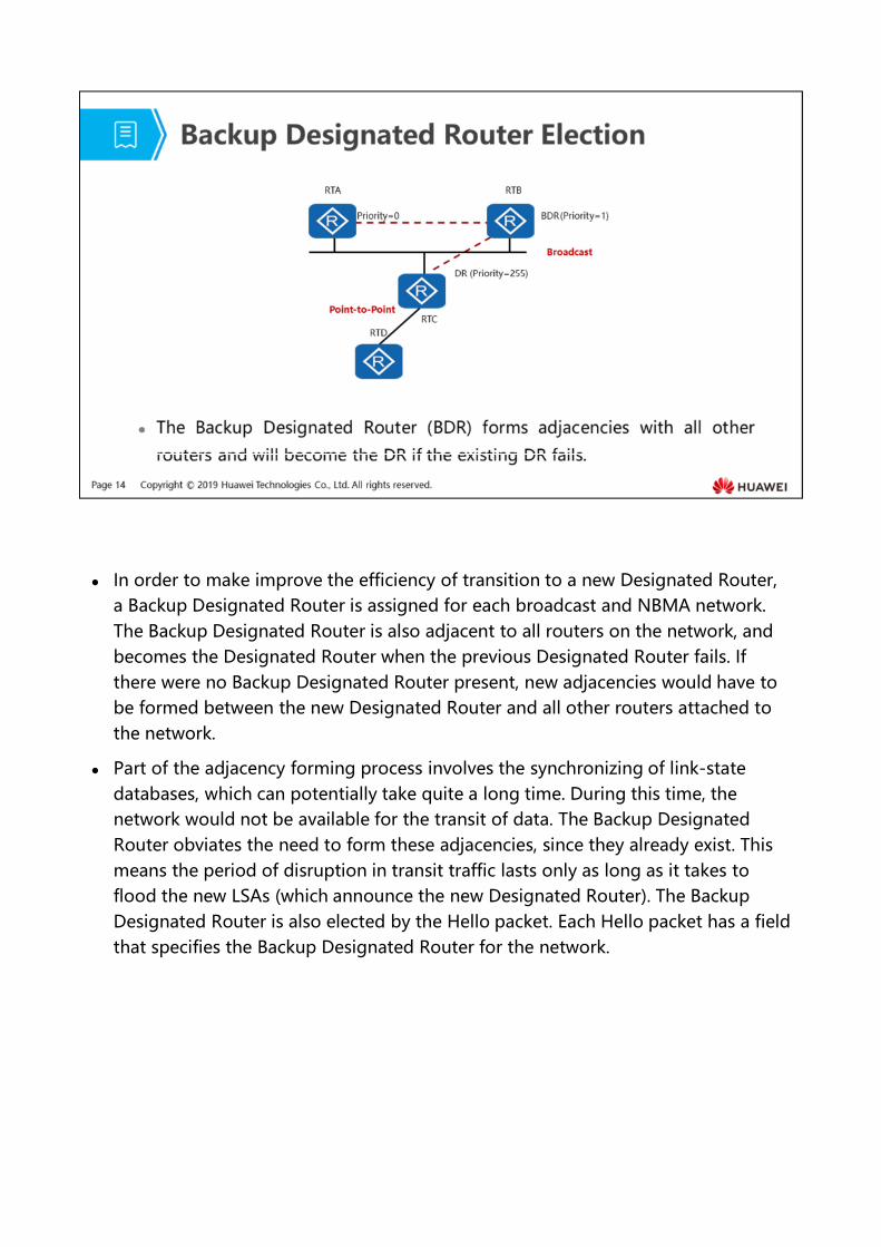
In order to make improve the efficiency of transition to a new Designated Router, a Backup Designated Router is assigned for each broadcast and NBMA network. The Backup Designated Router is also adjacent to all routers on the network, and becomes the Designated Router when the previous Designated Router fails. If there were no Backup Designated Router present, new adjacencies would have to be formed between the new Designated Router and all other routers attached to the network.
Part of the adjacency forming process involves the synchronizing of link-state databases, which can potentially take quite a long time. During this time, the network would not be available for the transit of data. The Backup Designated Router obviates the need to form these adjacencies, since they already exist. This means the period of disruption in transit traffic lasts only as long as it takes to flood the new LSAs (which announce the new Designated Router). The Backup Designated Router is also elected by the Hello packet. Each Hello packet has a field that specifies the Backup Designated Router for the network.
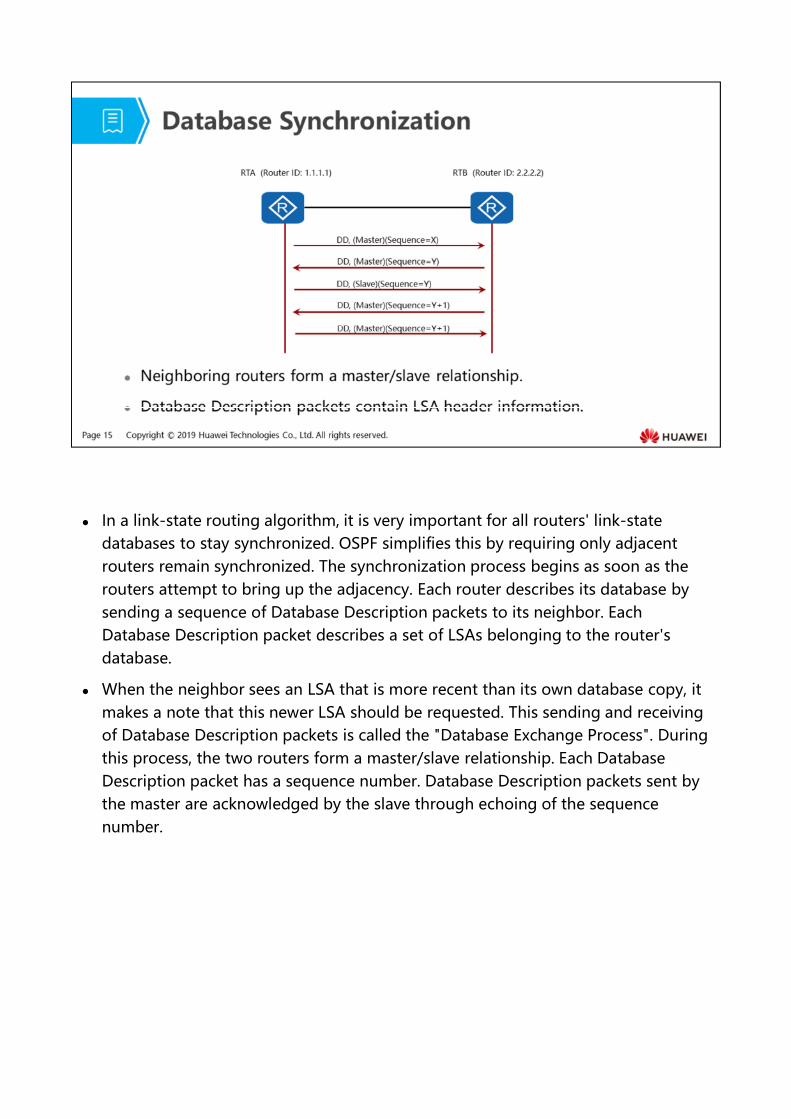
In a link-state routing algorithm, it is very important for all routers' link-state databases to stay synchronized. OSPF simplifies this by requiring only adjacent routers remain synchronized. The synchronization process begins as soon as the routers attempt to bring up the adjacency. Each router describes its database by sending a sequence of Database Description packets to its neighbor. Each Database Description packet describes a set of LSAs belonging to the router's database.
When the neighbor sees an LSA that is more recent than its own database copy, it makes a note that this newer LSA should be requested. This sending and receiving of Database Description packets is called the "Database Exchange Process". During this process, the two routers form a master/slave relationship. Each Database Description packet has a sequence number. Database Description packets sent by the master are acknowledged by the slave through echoing of the sequence number.
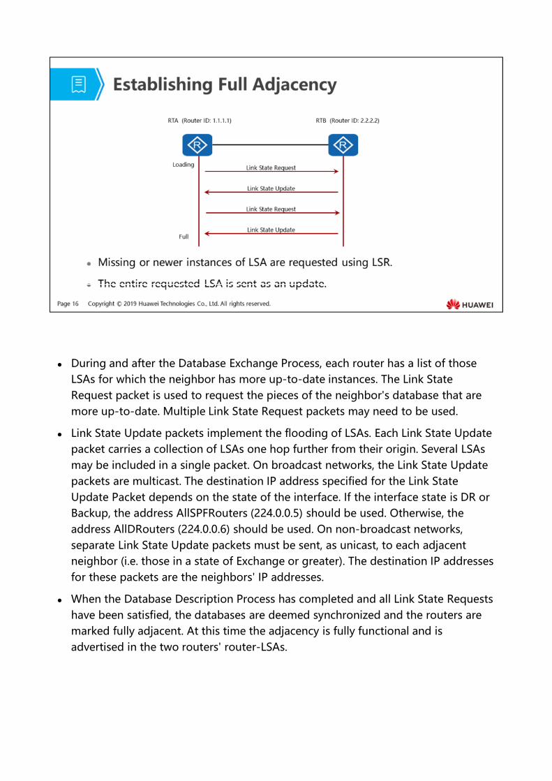
During and after the Database Exchange Process, each router has a list of those LSAs for which the neighbor has more up-to-date instances. The Link State Request packet is used to request the pieces of the neighbor's database that are more up-to-date. Multiple Link State Request packets may need to be used.
Link State Update packets implement the flooding of LSAs. Each Link State Update packet carries a collection of LSAs one hop further from their origin. Several LSAs may be included in a single packet. On broadcast networks, the Link State Update packets are multicast. The destination IP address specified for the Link State Update Packet depends on the state of the interface. If the interface state is DR or Backup, the address AllSPFRouters (224.0.0.5) should be used. Otherwise, the address AllDRouters (224.0.0.6) should be used. On non-broadcast networks, separate Link State Update packets must be sent, as unicast, to each adjacent neighbor (i.e. those in a state of Exchange or greater). The destination IP addresses for these packets are the neighbors' IP addresses.
When the Database Description Process has completed and all Link State Requests have been satisfied, the databases are deemed synchronized and the routers are marked fully adjacent. At this time the adjacency is fully functional and is advertised in the two routers' router-LSAs.
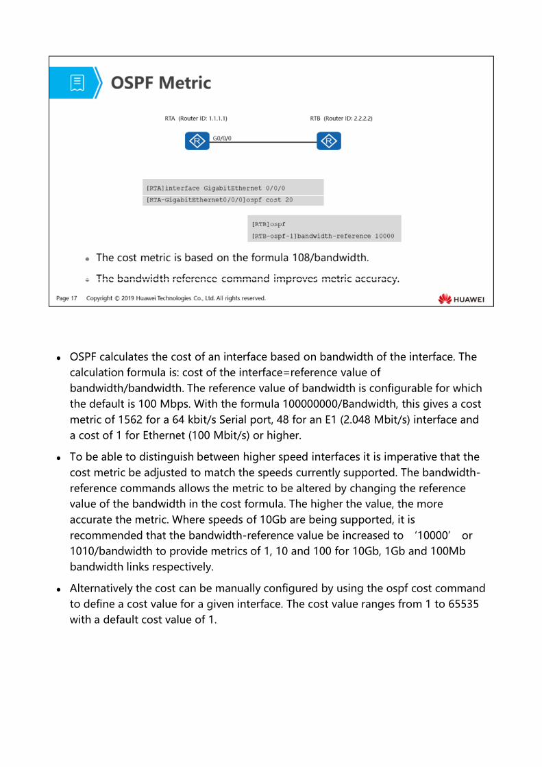
OSPF calculates the cost of an interface based on bandwidth of the interface. The calculation formula is: cost of the interface=reference value of bandwidth/bandwidth. The reference value of bandwidth is configurable for which the default is 100 Mbps. With the formula 100000000/Bandwidth, this gives a cost metric of 1562 for a 64 kbit/s Serial port, 48 for an E1 (2.048 Mbit/s) interface and a cost of 1 for Ethernet (100 Mbit/s) or higher.
To be able to distinguish between higher speed interfaces it is imperative that the cost metric be adjusted to match the speeds currently supported. The bandwidth-reference commands allows the metric to be altered by changing the reference value of the bandwidth in the cost formula. The higher the value, the more accurate the metric. Where speeds of 10Gb are being supported, it is recommended that the bandwidth-reference value be increased to ‘10000’ or 1010/bandwidth to provide metrics of 1, 10 and 100 for 10Gb, 1Gb and 100Mb bandwidth links respectively.
Alternatively the cost can be manually configured by using the ospf cost command to define a cost value for a given interface. The cost value ranges from 1 to 65535 with a default cost value of 1.
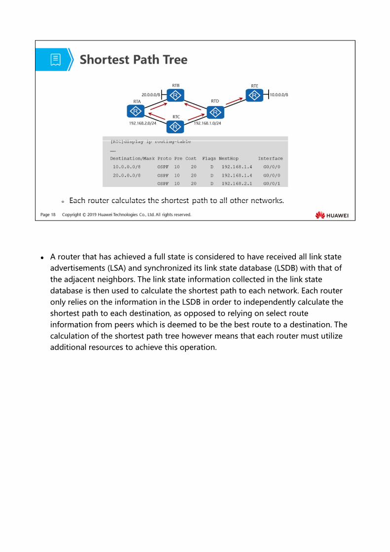
A router that has achieved a full state is considered to have received all link state advertisements (LSA) and synchronized its link state database (LSDB) with that of the adjacent neighbors. The link state information collected in the link state database is then used to calculate the shortest path to each network. Each router only relies on the information in the LSDB in order to independently calculate the shortest path to each destination, as opposed to relying on select route information from peers which is deemed to be the best route to a destination. The calculation of the shortest path tree however means that each router must utilize additional resources to achieve this operation.
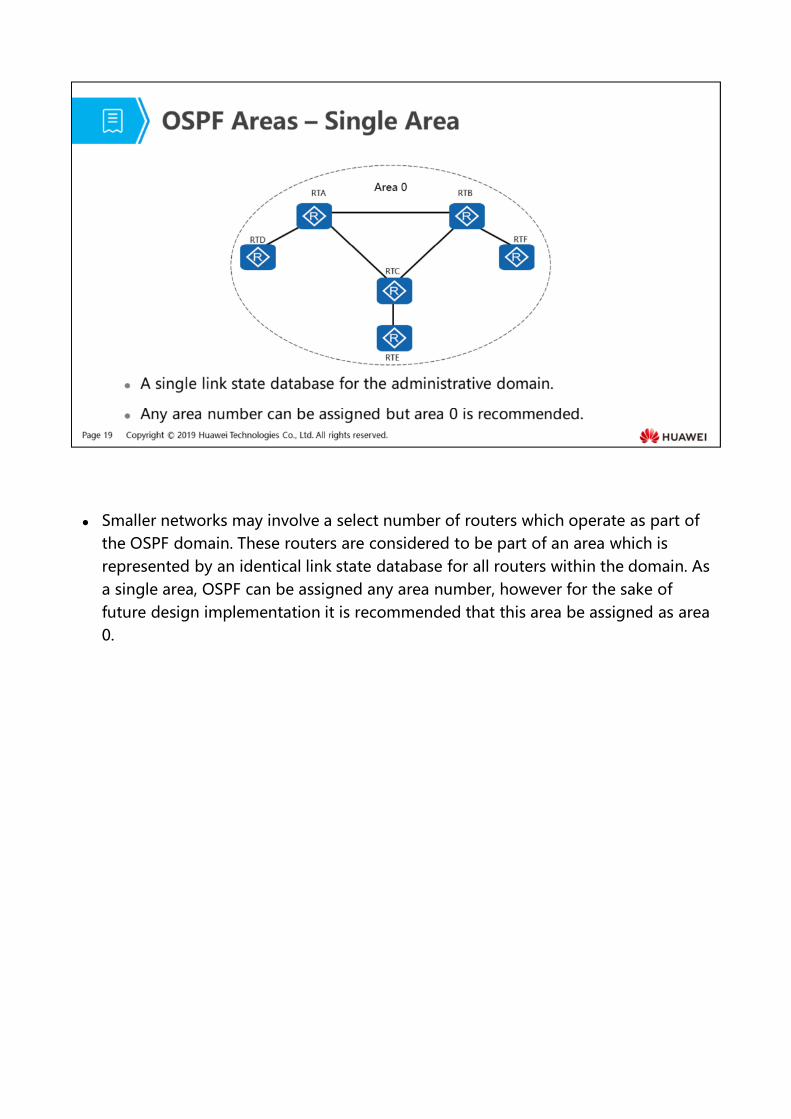
Smaller networks may involve a select number of routers which operate as part of the OSPF domain. These routers are considered to be part of an area which is represented by an identical link state database for all routers within the domain. As a single area, OSPF can be assigned any area number, however for the sake of future design implementation it is recommended that this area be assigned as area 0.
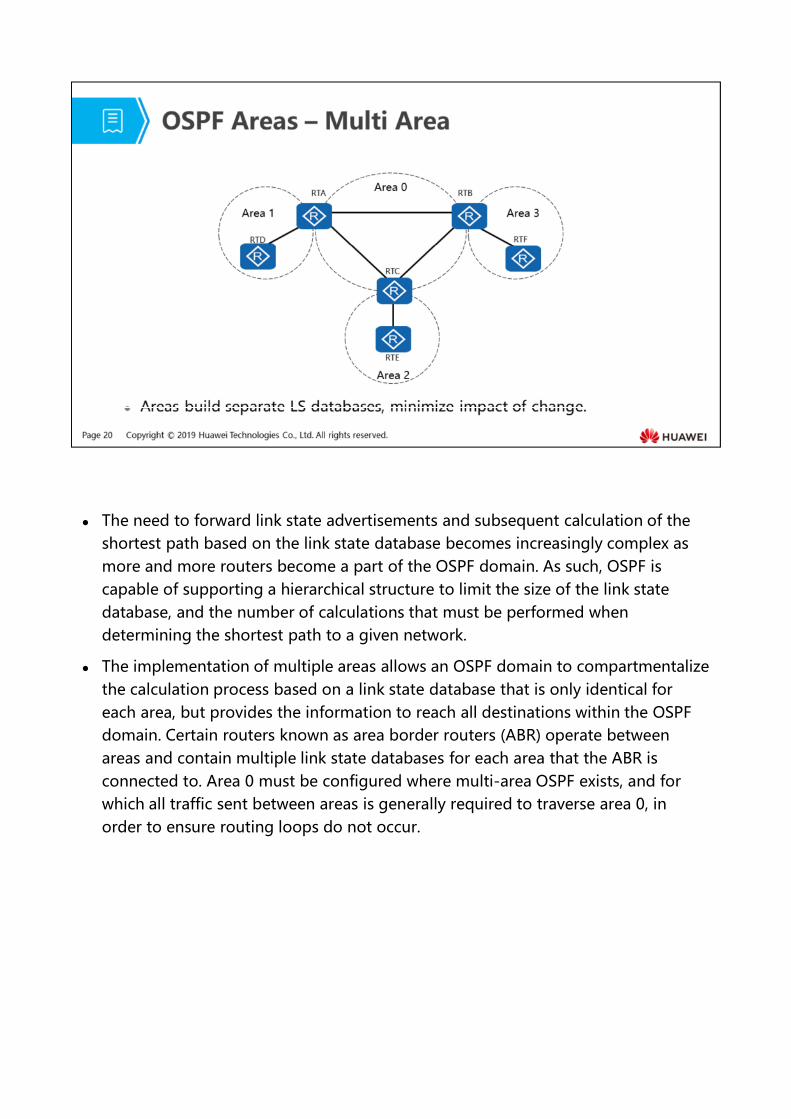
The need to forward link state advertisements and subsequent calculation of the shortest path based on the link state database becomes increasingly complex as more and more routers become a part of the OSPF domain. As such, OSPF is capable of supporting a hierarchical structure to limit the size of the link state database, and the number of calculations that must be performed when determining the shortest path to a given network.
The implementation of multiple areas allows an OSPF domain to compartmentalize the calculation process based on a link state database that is only identical for each area, but provides the information to reach all destinations within the OSPF domain. Certain routers known as area border routers (ABR) operate between areas and contain multiple link state databases for each area that the ABR is connected to. Area 0 must be configured where multi-area OSPF exists, and for which all traffic sent between areas is generally required to traverse area 0, in order to ensure routing loops do not occur.
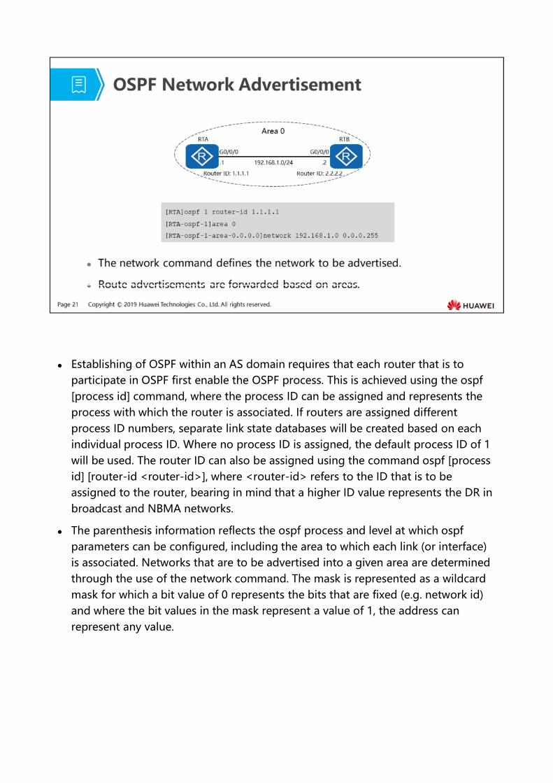
Establishing of OSPF within an AS domain requires that each router that is to participate in OSPF first enable the OSPF process. This is achieved using the ospf [process id] command, where the process ID can be assigned and represents the process with which the router is associated. If routers are assigned different process ID numbers, separate link state databases will be created based on each individual process ID. Where no process ID is assigned, the default process ID of 1 will be used. The router ID can also be assigned using the command ospf [process id] [router-id <router-id>], where <router-id> refers to the ID that is to be assigned to the router, bearing in mind that a higher ID value represents the DR in broadcast and NBMA networks.
The parenthesis information reflects the ospf process and level at which ospf parameters can be configured, including the area to which each link (or interface) is associated. Networks that are to be advertised into a given area are determined through the use of the network command. The mask is represented as a wildcard mask for which a bit value of 0 represents the bits that are fixed (e.g. network id) and where the bit values in the mask represent a value of 1, the address can represent any value.
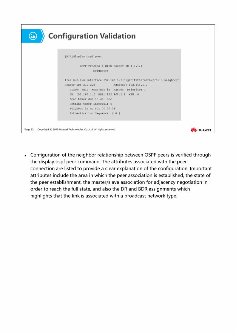
Configuration of the neighbor relationship between OSPF peers is verified through the display ospf peer command. The attributes associated with the peer connection are listed to provide a clear explanation of the configuration. Important attributes include the area in which the peer association is established, the state of the peer establishment, the master/slave association for adjacency negotiation in order to reach the full state, and also the DR and BDR assignments which highlights that the link is associated with a broadcast network type.
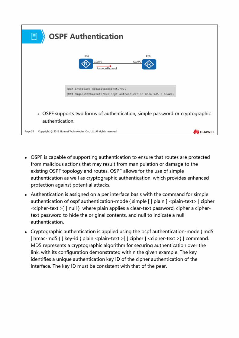
OSPF is capable of supporting authentication to ensure that routes are protected from malicious actions that may result from manipulation or damage to the existing OSPF topology and routes. OSPF allows for the use of simple authentication as well as cryptographic authentication, which provides enhanced protection against potential attacks.
Authentication is assigned on a per interface basis with the command for simple authentication of ospf authentication-mode { simple [ [ plain ] <plain-text> | cipher <cipher-text >] | null } where plain applies a clear-text password, cipher a cipher-text password to hide the original contents, and null to indicate a null authentication.
Cryptographic authentication is applied using the ospf authentication-mode { md5 | hmac-md5 } [ key-id { plain <plain-text >| [ cipher ] <cipher-text >} ] command. MD5 represents a cryptographic algorithm for securing authentication over the link, with its configuration demonstrated within the given example. The key identifies a unique authentication key ID of the cipher authentication of the interface. The key ID must be consistent with that of the peer.
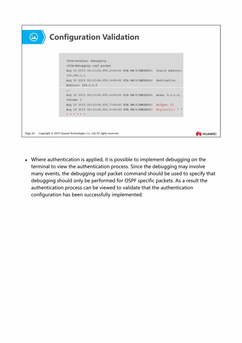
Where authentication is applied, it is possible to implement debugging on the terminal to view the authentication process. Since the debugging may involve many events, the debugging ospf packet command should be used to specify that debugging should only be performed for OSPF specific packets. As a result the authentication process can be viewed to validate that the authentication configuration has been successfully implemented.
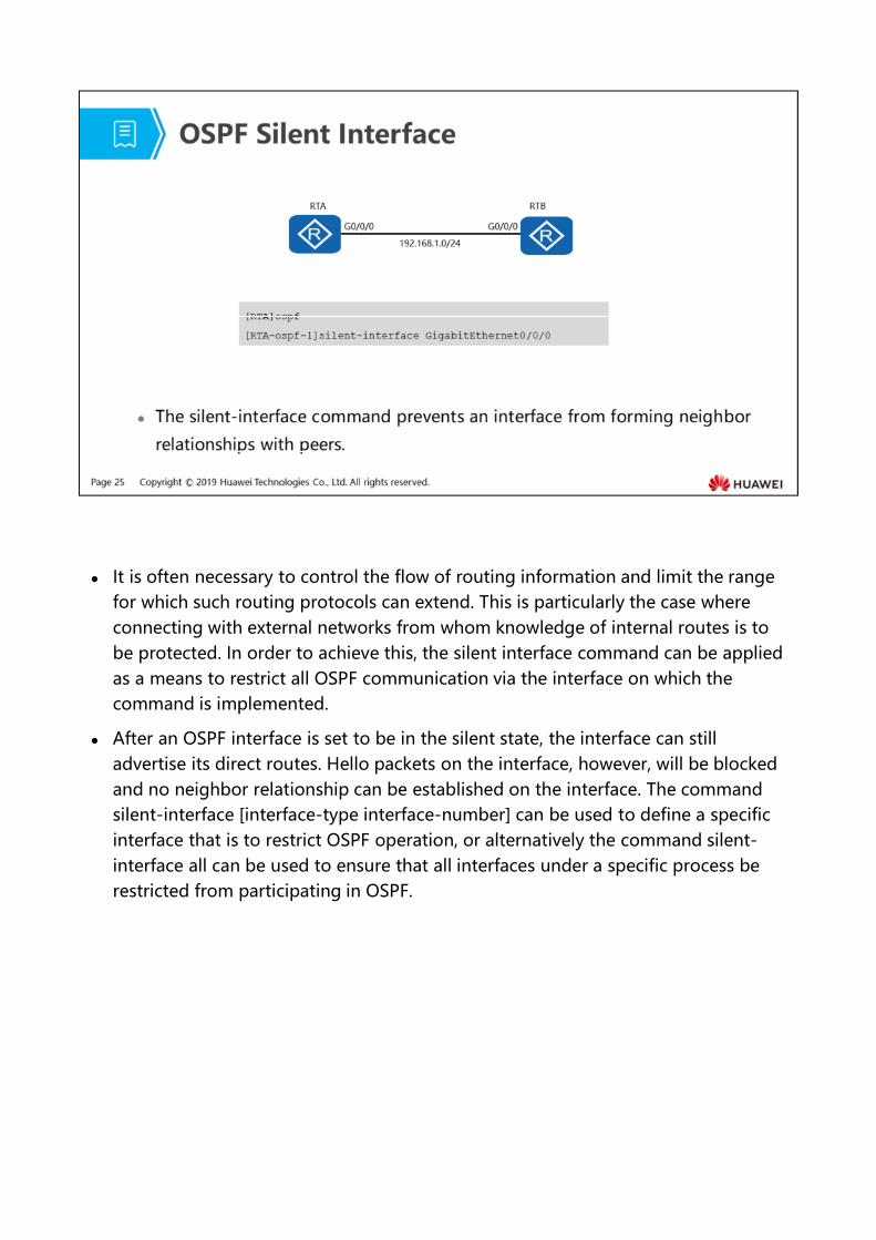
It is often necessary to control the flow of routing information and limit the range for which such routing protocols can extend. This is particularly the case where connecting with external networks from whom knowledge of internal routes is to be protected. In order to achieve this, the silent interface command can be applied as a means to restrict all OSPF communication via the interface on which the command is implemented.
After an OSPF interface is set to be in the silent state, the interface can still advertise its direct routes. Hello packets on the interface, however, will be blocked and no neighbor relationship can be established on the interface. The command silent-interface [interface-type interface-number] can be used to define a specific interface that is to restrict OSPF operation, or alternatively the command silent-interface all can be used to ensure that all interfaces under a specific process be restricted from participating in OSPF.
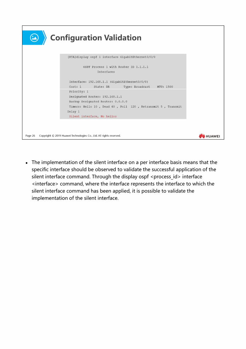
The implementation of the silent interface on a per interface basis means that the specific interface should be observed to validate the successful application of the silent interface command. Through the display ospf <process_id> interface <interface> command, where the interface represents the interface to which the silent interface command has been applied, it is possible to validate the implementation of the silent interface.
The dead interval is a timer value that is used to determine whether the propagation of OSPF Hello packets has ceased. This value is equivalent to four times the Hello interval, or 40 seconds by default on broadcast networks. In the event that the dead interval counts down to zero, the OSPF neighbor relationship will terminate.
The DR and BDR use the multicast address 224.0.0.6 to listen for link state updates when the OSPF network type is defined as broadcast.


![Open Shortest Path First Routing Under Random Early Detectionsd-research.uwaterloo.ca/papers/Networks-OSPF-Routing-with-RED.pdf · First (OSPF) routing protocol [35], where OSPF requires](https://img.pdfslide.us/doc/110x75/5f746308e2e9e43294254a6e/open-shortest-path-first-routing-under-random-early-detectionsd-first-ospf-routing.jpg)