Embed Size (px)
Citation preview
www.hbbolt.com • 1122 Harrison Street • San Francisco, CA 94103 • 415-861-8300 177
CIRCULAR SAW BLADESPOWER TOOL SERIES FOR THE CONTRACTOR
Exceptional features and superior quality, Thin Kerf
TENRYU’S comprehensive line of blades forportable and stationary power tools. More variety, better quality and greater value. Sizes range from 4" to 14" for most types of applications. The TENRYU PT SERIESgoes on to include thin kerf wood cutting blades designed especially for smooth cuts on miter and slide-compound. See below.
BLADE FEATURES:• Fully hardened, expertly tensioned tool steelbodies absorb impact, remain flat and true, and resist excess heat build-up.• High-grade, C-3, fine-grain tungsten carbide tips resist erosion for extended blade life.• Aggressive rake angles for maximum cutting speed and efficiency.• Each tip is precision honed on all four exposed surfaces. This minimizes micro-chipping along the sharp edge of the tip and resultsin a sharper, longer-lasting edge.• Thin kerf for less waste and lighter cutting performance (reduced feed pressure).• Inserted tooth design on some models greatly increases the body-to-tip braze area for greater support and tip strength.• Expansion slots and/or variable pitch gullets keep blade true under stressful work loads.• Can be resharpened for extended blade life.
POWER TOOL SERIES - Primarily for Portable Saws and Table SawsPART NO. DIA. TEETH ARBOR GRIND KERF RAKE APPLICATIONPT-10024 4" 24 10mm ATAF `.055" 18 For woodworking on Makita 4" trim sawPT-1006-1 4" 6 22mm FTG .157" 20 For very clean and accurate biscuit slots in all woodsPT-1006-2 4" 6 22mm ATAFR .157" 25/-15 For exceptionally clean and smooth biscuit slots in all woodsPT-11036 4-3/8" 36 20mm ATAF .063" 15 For fine trim work on corded Makita trim sawsPT-11536 4-1/2" 36 3/8" ATAF .063" 15 For clean and easy trim work on the Porter Cable trim sawPT-14036 5-1/2" 36 5/8" / 1/2" ATAF .063" 15 For fine and easy trim work on Makita or Skil circular sawsPT-15236 6" 36 1/2" ATAF .063" 15 For excellent results on 6" Porter Cable corded or cordless sawsPT-16524 6-1/2" 24 5/8"KO ATB .079" 20 For woodworking on 76-1/2" corded saws. FAST!PT-16524-T 6-1/2" 24 5/8"KO ATAF .059" 20 Ultra-thin for very fast and easy rok on 6-1/2" corded or cordless
sawsPT-16540 6-1/2" 40 5/8"KO ATB .079" 20 For finer cuts on corded 6-1/2" sawsPT-16540-CR 6-1/2" 40 BEVEL ATB .063" 18 For use on the CRAIN JAMB SAW for carpet/flooring installersPT-16540-T 6-1/2" 40 5/8"KO ATB .063" 18 ULTRA-THIN kerf for fine work on corded or cordless sawsPT-16552-T 6-1/2" 52 5/8"KO ATAF .063" 18 ULTRA-THIN kerf for SUPER clean work on 6-1/2" sawsPT-18516B 7-1/4" 16 5/8"KO ATB .073:" 27 Our super fast framing and ripping blade with INSERTED teethPT-18520B 7-1/4" 20 5/8"KO ATB .073" 27 Fast and Furious 20 tooth INSERTED TOOTH blade for framersPT-18524AM 7-1/4" 24 5/8"KO ATB .070" 20 The AMIGO 24 tooth contractor blade. Fast with long cutting lifePT-18524-P 7-1/4" 24 5/8"KO ATB .070" 20 BULLFROG. The choice when cutting pressure treated or wet
lumber. URETHANE COATEDPT-18524V 7-1/4" 24 5/8"KO ATB .070" 20 CITATION. the unique VARIABLE PITCH framing blade for AST,
smooth cuttingPT-18540 7-1/4" 40 5/8"KO ATB .073" 27 Spectacular INSERTED TOOTH finish blade. Great performancePT-18540B 7-1/4" 40 5/8"KO ATAF .063" 18 ULTRA-THIN kerf for finish cross-cutting. Bulk packagedPT-18540-T 7-1/4" 40 5/8"KO ATB .063" 18 ULTRA-THIN blade for finish work on circular or trim sawsPT-18552-T 7-1/4" 52 5/8"KO ATAF .063" 18 ULTRA-THIN, ultra-fine blade for trim work. For finest cutsPT-20360 8" 60 5/8"KO ATAF .087" 5 A no-nonsense clean cutting 8" woodcutting blade. Also for Panel
sawsPT21018 8-1/4" 18 5/8"KO ATB .075" 25 Fast cutting for woodworking and ripping on table or circular saws.
INSERTED TOOTH DESIGNPT-21040 8-1/4" 40 5/8"KO ATB .079" 15 The tremendously popular 8-1/4" Power Tool Series blade. for table
or portable sawsPT-21060 8-1/4" 60 5/8"KO ATAF .079" 12 For fine cuts in wood with a table saw or circular sawPT-26036 10-1/4" 36 5/8"KO ATAF .079" 20 For woodworking on modified circular saws
hbbolt_pgs_161_192_17061_template_NEW_USE 2/8/16 11:12 AM Page 177
www.hbbolt.com • 1122 Harrison Street • San Francisco, CA 94103 • 415-861-8300178
CIRCULAR SAW BLADES (Cont.)POWER TOOL SERIES FOR MITER AND SLIDE-MITER SAWS
The “PT” Series blades for miter, slide-miter, and radial arm saws range insizes from 8-1/2" for the popular Hitachi through 12" diameters.
EACH BLADE FEATURES:• Thin kerf design is easier on miter saw motors and brakes.• Fully hardened, expertly tensioned tool steel bodies.• Fine grain tungsten carbide tips with fine grit honing for keen edges.• Excellent price/value.
POWER TOOL SERIES - For Miter or Slide Miter SawsPART NO. DIA. TEETH ARBOR GRIND KERF RAKE APPLICATIONPT-21624 8-1/2" 24 5/8" ATB .087" 15 A fast cutting blade for use on 8-1/2" saws in thick woodPT-21640 8-1/2" 40 5/8" ATB .087" 15 A super blade for use on 8-1/2" saws in woodPT-21660-1 8-1/2" 60 5/8" ATAF .079" 5 A super performer on 8-1/2" miter sawsPT-21680 8-1/2" 80 5/8" ATAF .087" 10 For extra-clean cuts in wood and thin productsPT-23040 9" 40 5/8" ATAF .087" 5 Our Power Tool Series blade for 9" miter or table sawsPT-25540 10" 40 5/8" ATB .083" 0 Used for miter, radial arm or table sawsPT-25550 10" 50 5/8" ATAF .092" 15 INSERTED TEETH. For use on miter saws. Great valuePT-25560 10" 60 5/8" ATB .083" 0 Used for miter, radial arm or slide miter sawsPT-25560D 10" 60 5/8" TCG .087" 10 Triple chip woodworking blade for man-made wood materialPT-25572 10" 72 5/8" ATB .083" 0 Clean performance on miter sawsPT-25590 10" 90 5/8" ATAF .091" 10 For super clean cuts in thin wood or miter sawsPT-26036 10-1/4" 36 5/8"KO ATAF .079" 20 For woodworking on modified circular sawsPT-30560 12" 60 1" ATAF .094" 3 Thin kerf. Outstanding value. Excellent woodworking miter or radial
arm saw blade for thick stockPT-30580 12" 80 1" ATAF .094" 5 Thin kerf. Fine cut-off blades for woodworking on miter or radial
arm saws for medium stockPT-305100 12" 100 1" ATAF .094" 5 Thin kerf. Extra clean cuts in wood on your miter or radial arm saw
for thin stock
PT-21624
SILENCER SERIES FOR SLIDE-MITER SAWS, AND CROSSCUTTING WITH PORTABLE SAWS
EACH BLADE FEATURES:• New vibration dampening system featuring patented TENRYU resin bond filled laser cut body slots.• Meticulous, hand hammer plate tensioning for a flatter blade and truercuts.
Smoother Cuts Cleaner Edges Quieter Cutting Longer Sharp-Life
PART NO. DIA. TEETH ARBOR GRIND KERF RAKE APPLICATIONL-16552 6-1/2" 52 5/8"KO ATAF .063" 18 Extra smooth crosscuts using cordless and portable sawsSL-18552 7-1/4" 52 5/8"KO ATAF .063" 18 Extra smooth crosscuts using portable and circular sawsSL-21660 8-1/2" 60 5/8" ATAF .079" 5 Extra smooth cuts on 8-1/2" slide-miter sawsSL-25572 10" 72 5/8" ATAF .110" 10 Extra smooth cuts in various thickness wood on all types of miter
sawsSL-305100 12" 100 1" ATAF .110" 5 Extra smooth cuts in various thickness wood on all types of miter
saws
"Choose a saw blade with built-in noise and vibration dampening."OSHA's "Selection Rule No. 2 – Selecting a saw blade"
hbbolt_pgs_161_192_17061_template_NEW_USE 2/8/16 11:12 AM Page 178
www.hbbolt.com • 1122 Harrison Street • San Francisco, CA 94103 • 415-861-8300 179
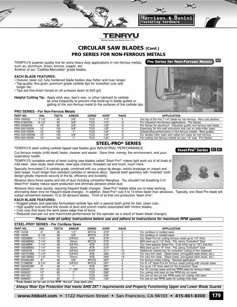
CIRCULAR SAW BLADES (Cont.)PRO SERIES FOR NON-FERROUS METALS
TENRYU’S superior quality line for extra heavy duty applications in non-ferrous metals,such as, aluminum, brass, bronze, copper, etc.Another of our “Cadillac/Mercedes” grade blades.
EACH BLADE FEATURES:• Heavier, laser cut, fully-hardened blade bodies stay flatter and truer longer.• Top-quality, fine-grain, premium grade carbide tips for smoother cuts and longer life.• Tips are fine-finish honed on all surfaces down to 600 grit.
Helpful Cutting Tip: Apply stick wax, bee’s wax, or other lubricant to carbide tip area frequently to prevent chip build-up in blade gullets orgalling of the non-ferrous metal to the surfaces of the carbide tips.
PRO SERIES - For Non-Ferrous MetalsPART NO. DIA. TEETH ARBOR GRIND KERF RAKE APPLICATIONPRA-18560D 7-1/4" 60 5/8" TCG .110" 0 Out top of the line 7-1/4" blade for non-ferrous. Also cuts plastics.PRA-21660DN 8-1/2" 60 5/8" TCG .110" -5 For industrial non-ferrous applications. Pro Series.PRA-25580DN 10" 80 5/8" TCG .126" -5 Pro Series for aluminum. Industrial quality non-ferrous saw blade.PRA-255100DN 10" 100 5/8" TCG .102" -5 Expecially for thin-wall extrusions and use on slide-miter saws.PRA-305100DN 12" 100 1" TCG .134" -5 Outstanding performance in non-ferrous metals. Best quality.PRA-305100DN2 12" 100 5/8" TCG .134" -5 For double miter saws and radial arm saws for non-ferrousPRA-355100DN 14" 100 1" TCG .134" -5 For cutting non-ferrous metals on your 14" saw. Pro Series
STEEL-PRO® SERIESTENRYU’S steel cutting carbide tipped saw blades give INDUSTRIAL PERFORMANCE.Cut ferrous metals (mild steel) faster, cleaner and easier. Save time, money, the environment, and yourrespiratory health.TENRYU'S complete series of steel cutting saw blades called “Steel-Pro®” makes light work out of all kinds ofmild steel: steel studs, steel sheets, steel pipe channel, threaded rod and much, much more.Specially formulated C-6 carbide grade, combined with our unique tip design, resists breakage on impact andlasts longer, much longer than standard carbides or abrasive discs. Special tooth geometry with “inserted” toothdesign greatly improves security of the tip, efficiency and durability.Abrasive discs throw sparks and lots of dust including unheathful fiberglass. You shouldn’t be breathing it in!Steel-Pro® blades reduce spark production and eliminate abrasive wheel dust.Abrasive discs wear quickly, requiring frequent blade changes. Steel-Pro® blades allow you to keep working;eliminating down time for frequent blade changes. In addition, Steel-Pro® cuts 5 to 10 times faster than abrasives. Typically, one Steel-Pro blade willoutlast somewhere between 15 to 30 abrasive blades. Think of all that non-productive “down time”.EACH BLADE FEATURES:• Rugged plates and specially formulated carbide tips with a special tooth grind for fast, clean cuts.• High quality cuts without the clouds of dust and scorch marks associated with friction blades.• Cool cuts that leave the work piece edge free of burrs.• Reduced cost-per-cut and maximized performance for the operator as a result of fewer blade changes.
STEEL-PRO® SERIES - For Cordless SawsPART NO. DIA. TEETH ARBOR GRIND KERF RAKE APPLICATIONPRF-15238 6" 38 1/2" MTCG .079" 0 For cordless or corded sawsPRF-16048 6-1/4" 48 5/8" MTCG .079" 0 For cordless or corded sawsPRF-18538BW 7-1/4" 38 5/8"KO ATB .079" 0 Our Steel-Pro for cutting ferrous metal up to 1/4" thickPRF-18538BW2 7-1/4" 38 20mm MTCG .079" 0 Mild steel up to 1/4" thick. Fits Jancy, Evolution® SawPRF-18548BW 7-1/4" 48 5/8"KO ATB .079" 0 Our most popular Steel-Pro. Cuts thick (up to 1/8") and thinPRF-18548BW2 7-1/4" 48 20mm ATB .079" 0 Mild steel up to1 /8" thick. Fits Jancy, Evolution® SawPRF-18556CB 7-1/4" 56 5/8"KO ATAF .071" -10 Additional carbide tips for smoother cutting of thin materialsPRF-18570CBN 7-1/4" 70 5/8"KO ATB .069" -10 For very thin steel. (Steel sheet, corrugated steel sheet, etc.)PRF-18570BW2 7-1/4" 70 20mm ATB .069" -10 For very thin steel. (Steel sheet, corrugated steel sheet, etc.)PRF-20348CBN 8" 48 5/8" MTCG .087" 0 For ferrous metal cutting. General applicationPRF-21048BW 8-1/4" 48 5/8"KO MTCG .087" 0 For 8-1/4" Steel-Pro for ferrous metal cutting with circular sawsPRF-23048CBN 9" 48 1" ATB .087" 0 For up to 1/8" thick steel on the Evolution® SawPRF-25550D 10" 50 1", 5/8" TCG .098" 0 For 10" circular saws and low RPM saws for ferrous metalPRF-30560D* 12" 60 1" TCG .098" 0 For cutting mild steel on low RPM dry cut sawsPRF-35572D* 14" 72 1" TCG .094" 0 For use on dry-cut low RPM saws for cutting mild steelPRF-40580D* 16" 80 1" TCG .102" 0 For use on low RPM saws for cutting mild steel* These blades are for use on low RPM “dry-cut” chop saws only.
Always Wear Eye Protection that meets ANSI Z87.1 requirements and Properly Functioning Upper and Lower Blade Guards
Please note all safety instructions before use and adhere to instructions for maximum RPM speeds.
hbbolt_pgs_161_192_17061_template_NEW_USE 2/8/16 11:12 AM Page 179
www.hbbolt.com • 1122 Harrison Street • San Francisco, CA 94103 • 415-861-8300180
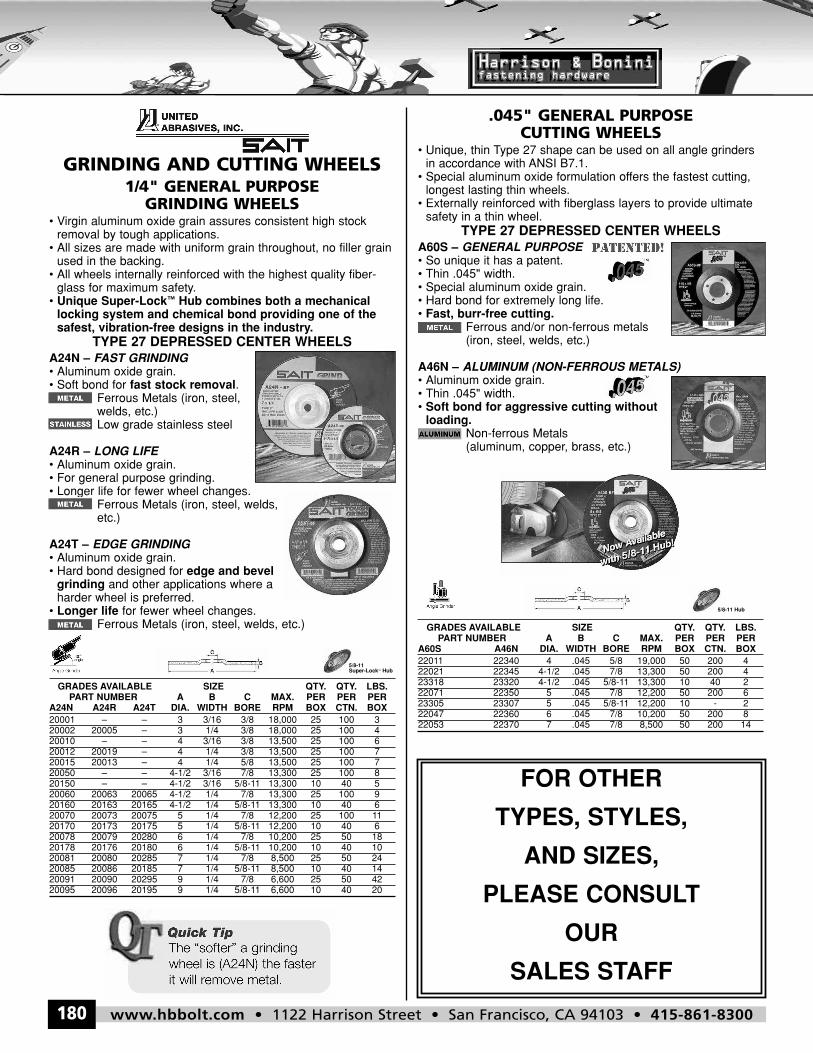
GRINDING AND CUTTING WHEELS1/4" GENERAL PURPOSEGRINDING WHEELS
• Virgin aluminum oxide grain assures consistent high stockremoval by tough applications.• All sizes are made with uniform grain throughout, no filler grainused in the backing.• All wheels internally reinforced with the highest quality fiber-glass for maximum safety.• Unique Super-Lock™ Hub combines both a mechanicallocking system and chemical bond providing one of thesafest, vibration-free designs in the industry.
TYPE 27 DEPRESSED CENTER WHEELSA24N – FAST GRINDING• Aluminum oxide grain.• Soft bond for fast stock removal.
Ferrous Metals (iron, steel,welds, etc.)Low grade stainless steel
A24R – LONG LIFE• Aluminum oxide grain.• For general purpose grinding.• Longer life for fewer wheel changes.
Ferrous Metals (iron, steel, welds,etc.)
A24T – EDGE GRINDING• Aluminum oxide grain.• Hard bond designed for edge and bevelgrinding and other applications where aharder wheel is preferred.• Longer life for fewer wheel changes.
Ferrous Metals (iron, steel, welds, etc.)
GRADES AVAILABLE SIZE QTY. QTY. LBS.PART NUMBER A B C MAX. PER PER PER
A24N A24R A24T DIA. WIDTH BORE RPM BOX CTN. BOX20001 – – 3 3/16 3/8 18,000 25 100 320002 20005 – 3 1/4 3/8 18,000 25 100 420010 – – 4 3/16 3/8 13,500 25 100 620012 20019 – 4 1/4 3/8 13,500 25 100 720015 20013 – 4 1/4 5/8 13,500 25 100 720050 – – 4-1/2 3/16 7/8 13,300 25 100 820150 – – 4-1/2 3/16 5/8-11 13,300 10 40 520060 20063 20065 4-1/2 1/4 7/8 13,300 25 100 920160 20163 20165 4-1/2 1/4 5/8-11 13,300 10 40 620070 20073 20075 5 1/4 7/8 12,200 25 100 1120170 20173 20175 5 1/4 5/8-11 12,200 10 40 620078 20079 20280 6 1/4 7/8 10,200 25 50 1820178 20176 20180 6 1/4 5/8-11 10,200 10 40 1020081 20080 20285 7 1/4 7/8 8,500 25 50 2420085 20086 20185 7 1/4 5/8-11 8,500 10 40 1420091 20090 20295 9 1/4 7/8 6,600 25 50 4220095 20096 20195 9 1/4 5/8-11 6,600 10 40 20
5/8-11Super-Lock™ Hub
.045" GENERAL PURPOSECUTTING WHEELS
• Unique, thin Type 27 shape can be used on all angle grindersin accordance with ANSI B7.1.• Special aluminum oxide formulation offers the fastest cutting,longest lasting thin wheels.• Externally reinforced with fiberglass layers to provide ultimatesafety in a thin wheel.
TYPE 27 DEPRESSED CENTER WHEELSA60S – GENERAL PURPOSE• So unique it has a patent.• Thin .045" width.• Special aluminum oxide grain.• Hard bond for extremely long life.• Fast, burr-free cutting.
Ferrous and/or non-ferrous metals(iron, steel, welds, etc.)
A46N – ALUMINUM (NON-FERROUS METALS)• Aluminum oxide grain.• Thin .045" width.• Soft bond for aggressive cutting withoutloading.
Non-ferrous Metals(aluminum, copper, brass, etc.)
GRADES AVAILABLE SIZE QTY. QTY. LBS.PART NUMBER A B C MAX. PER PER PER
A60S A46N DIA. WIDTH BORE RPM BOX CTN. BOX22011 22340 4 .045 5/8 19,000 50 200 422021 22345 4-1/2 .045 7/8 13,300 50 200 423318 23320 4-1/2 .045 5/8-11 13,300 10 40 222071 22350 5 .045 7/8 12,200 50 200 623305 23307 5 .045 5/8-11 12,200 10 - 222047 22360 6 .045 7/8 10,200 50 200 822053 22370 7 .045 7/8 8,500 50 200 14
5/8-11 Hub
FOR OTHER
TYPES, STYLES,
AND SIZES,
PLEASE CONSULT
OUR
SALES STAFF
hbbolt_pgs_161_192_17061_template_NEW_USE 2/8/16 11:13 AM Page 180
www.hbbolt.com • 1122 Harrison Street • San Francisco, CA 94103 • 415-861-8300 181
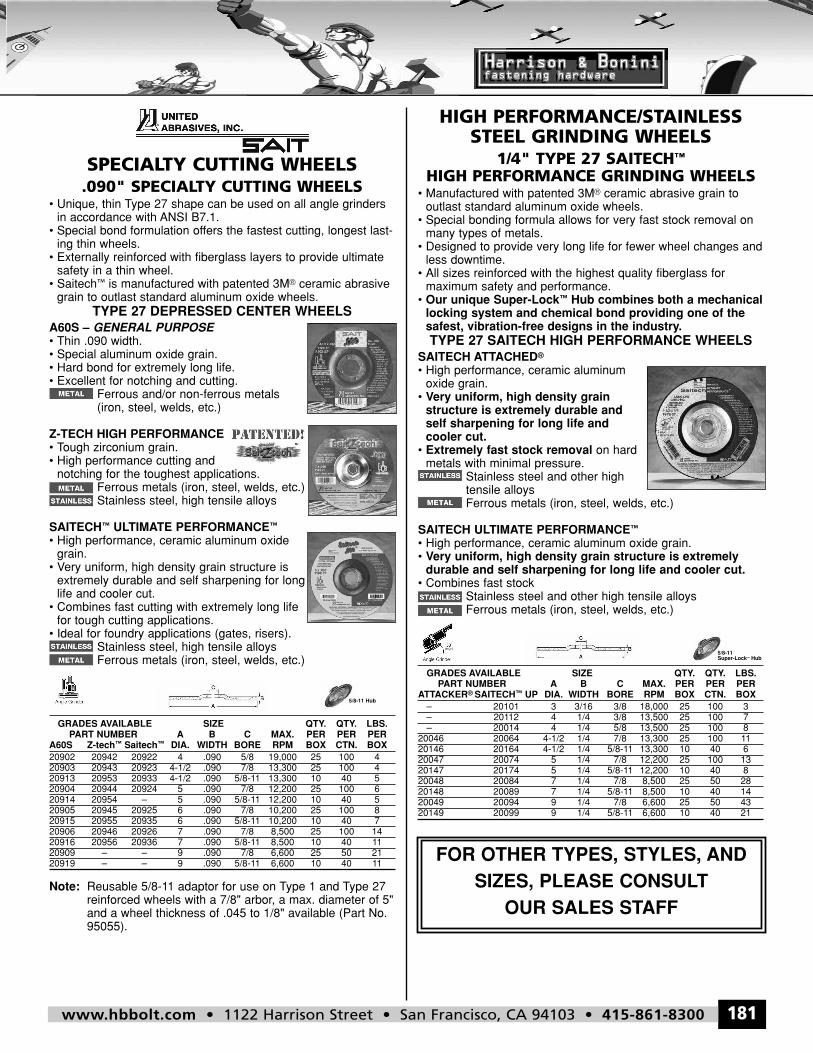
SPECIALTY CUTTING WHEELS.090" SPECIALTY CUTTING WHEELS
• Unique, thin Type 27 shape can be used on all angle grindersin accordance with ANSI B7.1.• Special bond formulation offers the fastest cutting, longest last-ing thin wheels.• Externally reinforced with fiberglass layers to provide ultimatesafety in a thin wheel.• Saitech™ is manufactured with patented 3M® ceramic abrasivegrain to outlast standard aluminum oxide wheels.
TYPE 27 DEPRESSED CENTER WHEELSA60S – GENERAL PURPOSE• Thin .090 width.• Special aluminum oxide grain.• Hard bond for extremely long life.• Excellent for notching and cutting.
Ferrous and/or non-ferrous metals(iron, steel, welds, etc.)
Z-TECH HIGH PERFORMANCE• Tough zirconium grain.• High performance cutting and notching for the toughest applications.
Ferrous metals (iron, steel, welds, etc.)Stainless steel, high tensile alloys
SAITECH™ ULTIMATE PERFORMANCE™• High performance, ceramic aluminum oxidegrain.• Very uniform, high density grain structure isextremely durable and self sharpening for longlife and cooler cut.• Combines fast cutting with extremely long lifefor tough cutting applications.• Ideal for foundry applications (gates, risers).
Stainless steel, high tensile alloysFerrous metals (iron, steel, welds, etc.)
GRADES AVAILABLE SIZE QTY. QTY. LBS.PART NUMBER A B C MAX. PER PER PER
A60S Z-tech™ Saitech™ DIA. WIDTH BORE RPM BOX CTN. BOX20902 20942 20922 4 .090 5/8 19,000 25 100 420903 20943 20923 4-1/2 .090 7/8 13,300 25 100 420913 20953 20933 4-1/2 .090 5/8-11 13,300 10 40 520904 20944 20924 5 .090 7/8 12,200 25 100 620914 20954 – 5 .090 5/8-11 12,200 10 40 520905 20945 20925 6 .090 7/8 10,200 25 100 820915 20955 20935 6 .090 5/8-11 10,200 10 40 720906 20946 20926 7 .090 7/8 8,500 25 100 1420916 20956 20936 7 .090 5/8-11 8,500 10 40 1120909 – – 9 .090 7/8 6,600 25 50 2120919 – – 9 .090 5/8-11 6,600 10 40 11
Note: Reusable 5/8-11 adaptor for use on Type 1 and Type 27reinforced wheels with a 7/8" arbor, a max. diameter of 5"and a wheel thickness of .045 to 1/8" available (Part No.95055).
5/8-11 Hub
HIGH PERFORMANCE/STAINLESSSTEEL GRINDING WHEELS
1/4" TYPE 27 SAITECH™HIGH PERFORMANCE GRINDING WHEELS• Manufactured with patented 3M® ceramic abrasive grain to outlast standard aluminum oxide wheels.• Special bonding formula allows for very fast stock removal onmany types of metals.• Designed to provide very long life for fewer wheel changes andless downtime.• All sizes reinforced with the highest quality fiberglass for maximum safety and performance.• Our unique Super-Lock™ Hub combines both a mechanicallocking system and chemical bond providing one of thesafest, vibration-free designs in the industry.TYPE 27 SAITECH HIGH PERFORMANCE WHEELS
SAITECH ATTACHED®• High performance, ceramic aluminumoxide grain.• Very uniform, high density grainstructure is extremely durable andself sharpening for long life and cooler cut.• Extremely fast stock removal on hardmetals with minimal pressure.
Stainless steel and other hightensile alloysFerrous metals (iron, steel, welds, etc.)
SAITECH ULTIMATE PERFORMANCE™• High performance, ceramic aluminum oxide grain.• Very uniform, high density grain structure is extremelydurable and self sharpening for long life and cooler cut.• Combines fast stock
Stainless steel and other high tensile alloysFerrous metals (iron, steel, welds, etc.)
GRADES AVAILABLE SIZE QTY. QTY. LBS.PART NUMBER A B C MAX. PER PER PER
ATTACKER® SAITECH™ UP DIA. WIDTH BORE RPM BOX CTN. BOX– 20101 3 3/16 3/8 18,000 25 100 3– 20112 4 1/4 3/8 13,500 25 100 7– 20014 4 1/4 5/8 13,500 25 100 8
20046 20064 4-1/2 1/4 7/8 13,300 25 100 1120146 20164 4-1/2 1/4 5/8-11 13,300 10 40 620047 20074 5 1/4 7/8 12,200 25 100 1320147 20174 5 1/4 5/8-11 12,200 10 40 820048 20084 7 1/4 7/8 8,500 25 50 2820148 20089 7 1/4 5/8-11 8,500 10 40 1420049 20094 9 1/4 7/8 6,600 25 50 4320149 20099 9 1/4 5/8-11 6,600 10 40 21
5/8-11Super-Lock™ Hub
FOR OTHER TYPES, STYLES, ANDSIZES, PLEASE CONSULT
OUR SALES STAFF
hbbolt_pgs_161_192_17061_template_NEW_USE 2/8/16 11:13 AM Page 181
www.hbbolt.com • 1122 Harrison Street • San Francisco, CA 94103 • 415-861-8300182
TAPEBLACK ELECTRICAL TAPE
• Flame retardant, cold weatherresistant.• U.L. approved.• 7 mil vinyl.
PART NO. SIZE CASE QTY. CASE WEIGHTETB 3/4" x 60 ft. 10 / 200 36.00
GENERAL PURPOSE DUCTape™(PRINT-WRAPPED)
• Utility grade, poly coated cloth backing witha very aggressive adhesive that bonds toalmost any surface.• Good comformability, is water resistant andtear resistant.
PART ROLL CASE CASE CASE CASENO. DIMENSIONS QTY. SIZE CUBE WEIGHTDT 260 1.87 in. x 60 yds 24 12 x 12 x 11.62 1.1 32. (48mm x 54.8m)
SAFETY TAPECAUTION TAPE
• Non-pressure sensitive vinyl barri-cade ribbon.• High visibility, 3 in. wide.• A variety of legends available suchas: “Danger Do Not Enter” (Red)and “Caution Do Not Enter” (Yellow).
PART ROLL CASE CASENO. DIMENSIONS LEGEND QTY. WEIGHTCT 3 in. x 1,000 ft. Caution 8 23.04DANGER TAPE 3 in. x 1,000 ft. Danger 8 20.00
SYNTHETIC LEATHERMECHANIC‘S GLOVES
99PLUS-BLK• Titan 2® synthetic leather palm.• Reinforced palm and fingers.• Snug spandex fit.PART NO. SIZES99PLUS-BLK 5 - 2XL
99PLUS-BLUE
• Blue version of 99PLUS-BLK.
PART NO. SIZES99PLUS-BLUE 5 - 2XL
99PRO-BLK• Titan 2® synthetic leather palm.• Single palm dexterity.• Sweat wipe.• Snug spandex fit.PART NO. SIZES99PRO-BLK 5 - 2XL
19FX-ORA
• Orange version of 19FX-BLK.
PART NO. SIZES10FX-ORA 5 - 2XL
19FX-BLK• Synthetic leather palm.• Reinforced palm.• Snug spandex fit.PART NO. SIZES19FX-BLK 5 - 2XL
hbbolt_pgs_161_192_17061_template_NEW_USE 2/8/16 11:13 AM Page 182
www.hbbolt.com • 1122 Harrison Street • San Francisco, CA 94103 • 415-861-8300 183
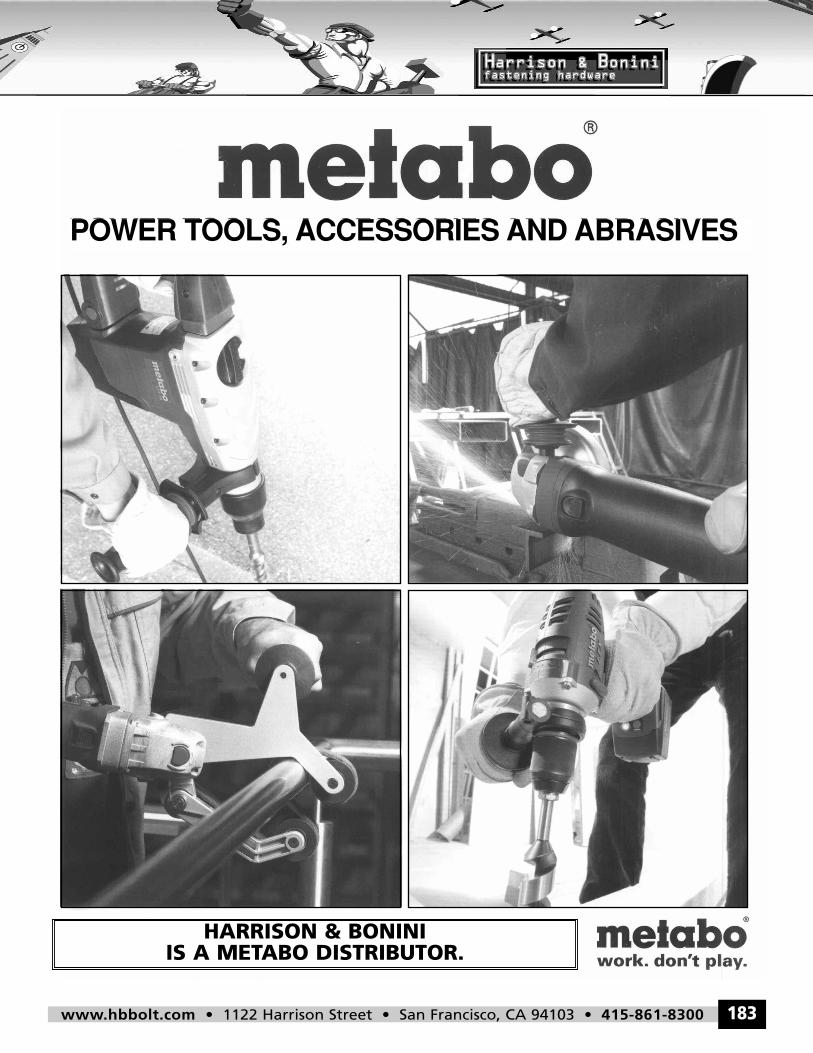
POWER TOOLS, ACCESSORIES AND ABRASIVES
HARRISON & BONINIIS A METABO DISTRIBUTOR.
hbbolt_pgs_161_192_17061_template_NEW_USE 2/8/16 11:13 AM Page 183
www.hbbolt.com • 1122 Harrison Street • San Francisco, CA 94103 • 415-861-8300184
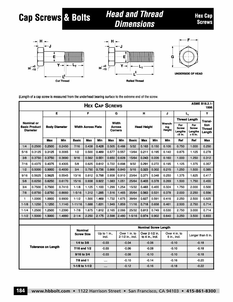
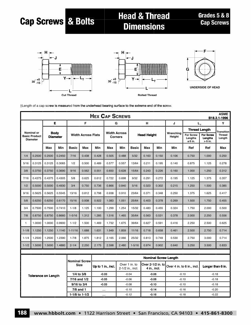
Cap Screws & Bolts Head and ThreadDimensions
Hex CapScrews
H
LT
L
E G
F
Cut Thread Rolled Thread
H
LT
L
E
Y30
o +0-15
Y
J
30o +0-15
UNDERSIDE OF HEAD
J
HEX CAP SCREWSASME B18.2.1-
1996
Nominal orBasic Product
Diameter
E F G H J LT
Y
Body Diameter Width Across FlatsWidth
AcrossCorners
Head HeightWrench-
ingHeight
Thread LengthTransi-
tionThreadLength
ForScrew
Lengths≤6 in.
ForScrew
Lengths> 6 in.
Max Min Basic Max Min Max Min Basic Max Min Min Ref Ref Max
1/4 0.2500 0.2500 0.2450 7/16 0.438 0.428 0.505 0.488 5/32 0.163 0.150 0.106 0.750 1.000 0.250
5/16 0.3125 0.3125 0.3065 1/2 0.500 0.489 0.577 0.557 13/64 0.211 0.195 0.140 0.875 1.125 0.278
3/8 0.3750 0.3750 0.3690 9/16 0.562 0.551 0.650 0.628 15/64 0.243 0.226 0.160 1.000 1.250 0.312
7/16 0.4375 0.4375 0.4305 5/8 0.625 0.612 0.722 0.698 9/32 0.291 0.272 0.195 1.125 1.375 0.357
1/2 0.5000 0.5000 0.4930 3/4 0.750 0.736 0.866 0.840 5/16 0.323 0.302 0.215 1.250 1.500 0.385
9/16 0.5625 0.5625 0.5545 13/16 0.812 0.798 0.938 0.910 23/64 0.371 0.348 0.250 1.375 1.625 0.417
5/8 0.6250 0.6250 0.6170 15/16 0.938 0.922 1.083 1.051 25/64 0.403 0.378 0.269 1.500 1.750 0.455
3/4 0.7500 0.7500 0.7410 1-1/8 1.125 1.100 1.299 1.254 15/32 0.483 0.455 0.324 1.750 2.000 0.500
7/8 0.8750 0.8750 0.8660 1-5/16 1.312 1.285 1.516 1.465 35/64 0.563 0.531 0.378 2.000 2.250 0.556
1 1.0000 1.0000 0.9900 1-1/2 1.500 1.469 1.732 1.675 39/64 0.627 0.591 0.416 2.250 2.500 0.625
1-1/8 1.1250 1.1250 1.1140 1-11/16 1.688 1.631 1.949 1.859 11/16 0.718 0.658 0.461 2.500 2.750 0.714
1-1/4 1.2500 1.2500 1.2390 1-7/8 1.875 1.812 2.165 2.066 25/32 0.813 0.749 0.530 2.750 3.000 0.714
1-1/2 1.5000 1.5000 1.4880 2-1/4 2.250 2.175 2.598 2.480 1-5/16 0.974 0.902 0.640 3.250 3.500 0.833
Tolerance on Length
NominalScrew Size
Nominal Screw Length
Up to 1 in.,incl.
Over 1 in. to2-1/2 in., incl.
Over 2-1/2 in.to 4 in., incl.
Over 4 in. to6 in., incl. Longer than 6 in.
1/4 to 3/8 -0.03 -0.04 -0.06 -0.10 -0.18
7/16 and 1/2 -0.03 -0.06 -0.08 -0.10 -0.18
9/16 to 3/4 -0.03 -0.08 -0.10 -0.10 -0.18
7/8 and 1 .... -0.10 -0.14 -0.16 -0.20
1-1/8 to 1-1/2 .... -0.12 -0.16 -0.18 -0.22
Cap Screws & BoltsCap Screws Head and ThreadHead and Thread Hex CapCap Screws
HJ
& BoltsCap Screws
E
L
E
Y
Dimensions
H
E
J
Dimensions
G
F
ScrewsHex Cap
F
‡Length of a cap screw is measured from the underhead bearing sur
-15+0o
30
‡L
‡Length of a cap screw is measured from the underhead bearing sur
Cut Thread
TL
L‡
Y
CEXH
‡L
face to the extreme end of the screw‡Length of a cap screw is measured from the underhead bearing sur
TL
L‡
Rolled Thread
Y-15+0o
30
CREWSSAPC
.face to the extreme end of the screw
Rolled Thread
UNDERSIDE OF HEADUNDERSIDE OF HEAD
1996ASME B18.2.1-
Max
Body DiameterDiameter
Basic ProductNominal or
1/4 0.2500 0.2500
0.31250.31255/16
MaxBasicMinMax
Width Across FlatsBody Diameter
E F
0.2500 0.2450 7/16 0.438 0.428
0.4890.5001/20.30650.3125
MaxBasicMinMaxMin
Head HeightCornersAcrossWidth
Width Across Flats
G
0.428 0.505 0.488 5/32 0.163
0.21113/640.5570.5770.489
RefMinMinMax
6 in.≤Lengths
ScrewFor
Thread Length
Heighting
Wrench-Head Height
TLJH
0.163 0.150 0.106 0.750
0.8750.1400.1950.211
MaxRef
> 6 in.LengthsScrew
For
LengthThread
tionTransi-
Thread Length
Y
1.000 0.250
0.2781.125
3/8 0.3750 0.3750
0.43750.43757/16
1/2 0.5000 0.5000
0.56250.56259/16
5/8 0.6250 0.6250
0.75000.75003/4
7/8 0.8750 0.8750
1.00001.00001
0.3750 0.3690 9/16 0.562 0.551
0.6120.6255/80.43050.4375
0.5000 0.4930 3/4 0.750 0.736
0.7980.81213/160.55450.5625
0.6250 0.6170 15/16 0.938 0.922
1.1001.1251-1/80.74100.7500
0.8750 0.8660 1-5/16 1.312 1.285
1.4691.5001-1/20.99001.0000
0.551 0.650 0.628 15/64 0.243
0.2919/320.6980.7220.612
0.736 0.866 0.840 5/16 0.323
0.37123/640.9100.9380.798
0.922 1.083 1.051 25/64 0.403
0.48315/321.2541.2991.100
1.285 1.516 1.465 35/64 0.563
0.62739/641.6751.7321.469
0.243 0.226 0.160 1.000
1.1250.1950.2720.291
0.323 0.302 0.215 1.250
1.3750.2500.3480.371
0.403 0.378 0.269 1.500
1.7500.3240.4550.483
0.563 0.531 0.378 2.000
2.2500.4160.5910.627
1.250 0.312
0.3571.375
1.500 0.385
0.4171.625
1.750 0.455
0.5002.000
2.250 0.556
0.6252.500
1-1/8 1.1250 1.1250
1.25001.25001-1/4
1-1/2 1.5000 1.5000
Tolerance on Length
1.1250 1.1140 1-11/16 1.688 1.631
1.8121.8751-7/81.23901.2500
1.5000 1.4880 2-1/4 2.250 2.175
Screw SizeNominal
Tolerance on Length1/4 to 3/8
7/16 and 1/2
1.631 1.949 1.859 11/16 0.718
0.81325/322.0662.1651.812
2.175 2.598 2.480 1-5/16 0.974
to 4 in., incl.Over 2-1/2 in.
2-1/2 in., incl.Over 1 in. to
incl.Up to 1 in.,
Nominal Screw Length
-0.03 -0.04
-0.06-0.03
0.718 0.658 0.461 2.500
2.7500.5300.7490.813
0.974 0.902 0.640 3.250
6 in., incl.Over 4 in. to
to 4 in., incl.Over 2-1/2 in.
Nominal Screw Length
-0.06 -0.10
-0.10-0.08
2.750 0.714
0.7143.000
3.500 0.833
Longer than 6 in.
-0.18
-0.18
74
Tolerance on Length 7/16 and 1/2
9/16 to 3/4
7/8 and 1
1-1/8 to 1-1/2
-0.06-0.03
-0.03 -0.08
-0.10....
.... -0.12
-0.10-0.08
-0.10 -0.10
-0.16-0.14
-0.16 -0.18
-0.18
-0.18
-0.20
-0.22
hbbolt_pgs_161_192_17061_template_NEW_USE 2/8/16 11:13 AM Page 184
www.hbbolt.com • 1122 Harrison Street • San Francisco, CA 94103 • 415-861-8300 185
Bolts & Cap Screws
x
xF5 9 3-C
xF5 9 3-G
Mechanical &Performance Data
Hex Cap Screws, Gr-2,18-8 & 316 Stainless
Description A low or medium carbon steel, externally threaded mechanical device 1/4" diameter or larger, with a trimmed hex head and awasher face on the bearing surface.
Applications/Advantages
Economical for use in non-critical applications where the fastener is not subject to extreme temperatures or stress beyond the limitslisted herein.
Material AISI 1006 - 1050 or equivalent steel.
Hardness1/4 through 3/4 in. diameter, 6 in. and shorter in length: Rockwell B80 - B100.
1/4 through 3/4 in. diameter, over 6 in. in length: Rockwell B70 - B100.7/8 through 1-1/2 in. diameter, all lengths: Rockwell B70 - B100.
Proof Load1/4 through 3/4 in. diameter, 6 in. and shorter in length: 55,000 psi.
1/4 through 3/4 in. diameter, over 6 in. in length: 33,000 psi.7/8 through 1-1/2 in. diameter, all lengths: 33,000 psi.
Yield Strength*1/4 through 3/4 in. diameter, 6 in. and shorter in length: 57,000 psi. minimum.
1/4 through 3/4 in. diameter, over 6 in. in length: 36,000 psi. minimum.7/8 through 1-1/2 in. diameter, all lengths: 36,000 psi. minimum.
Tensile Strength1/4 through 3/4 in. diameter, 6 in. and shorter in length: 74,000 psi. minimum.
1/4 through 3/4 in. diameter, over 6 in. in length: 60,000 psi. minimum.7/8 through 1-1/2 in. diameter, all lengths: 60,000 psi. minimum.
Elongation* 18% minimum (all diameters)
Reduction of Area* 35% minimum (all sizes)
Plating See Appendix-A for plating information
Description 18-8 and 316 stainless steel cap screws are both made from austenitic alloys as described below.
Applications/Advantages
18-8: Used in products that require general atmospheric corrosion resistance, such as chemical and food-processing equipment.Some chemical environments may require special corrosion resistant materials and precautions.
316: The molybdenum content gives this type of stainless even greater corrosion resistance than 18-8 as well as superior strengthat high temperatures.
Material18-8: A cap screw made from one of the following austenitic alloys: 303, 303Se, 304, XM7, all of which are characterized as having
a chromium content of 17-19% and nickel content of 8-10%.316: A cap screw made from 316 stainless steel, an austenitic alloy which differs from 18-8 by its molybdenum content (2-3%) and
a higher nickel content (10-14%).
Heat TreatmentThe austenitic alloys develop their strength through work hardening during the fastener manufacturing process, as seen from the
hardness properties below. The only heat treatment normally available on austenitic stainless alloys is annealing, which is done atapproximately 1900°F to a dead soft condition and is not normally thermally reversible.
Hardness 1/4 through 5/8 in. diameter: Rockwell B95 - C323/4 through 1 in. diameter: Rockwell B80 - C32
Yield Strength* 1/4 through 5/8 in. diameter, 2.25D and longer: 65,000 psi. minimum3/4" (2.25D & longer) & 7/8 through 1 in. diameter (3D & longer): 45,000 psi. minimum
Tensile Strength 1/4 through 5/8 in. diameter, 2.25D and longer: 100,000 - 150,000 psi.3/4" (2.25D & longer) & 7/8 through 1 in. diameter (3D & longer): 85,000 - 140,000 psi.
Elongation in 4D* 1/4 through 5/8 in. diameter: 20% minimum; 3/4 through 1 in. diameter: 25% minimum.
Hex Cap Screws, Gr-2,Hex Cap Screws, Gr Mechanical &Mechanical & Cap Bolts & Cap Screws18-8 & 316 Stainless
Description
AdvantagesApplications/
18-8 & 316 Stainless
GRADE-2 HEX CAP SCREW
Performance Data
A low or medium carbon steel, externally threaded mechanical device 1/4" diameter or larger, with a trimmed hex head and a
Applications/ Economical for use in non-critical applications where the fastener is not subject to extreme temperatures or stress beyond the
Performance Data
GRADE-2 HEX CAP SCREW
washer face on the bearing surface.A low or medium carbon steel, externally threaded mechanical device 1/4" diameter or larger, with a trimmed hex head and a
listed herein.Economical for use in non-critical applications where the fastener is not subject to extreme temperatures or stress beyond the
Cap Bolts &Performance Data
GRADE-2 HEX CAP SCREW
washer face on the bearing surface.A low or medium carbon steel, externally threaded mechanical device 1/4" diameter or larger, with a trimmed hex head and a
listed herein.Economical for use in non-critical applications where the fastener is not subject to extreme temperatures or stress beyond the
Cap Screws
x
A low or medium carbon steel, externally threaded mechanical device 1/4" diameter or larger, with a trimmed hex head and a
limitsEconomical for use in non-critical applications where the fastener is not subject to extreme temperatures or stress beyond the
**
Advantages
Material
Hardness
Proof Load
Yield Strength*
1/4 through 3/4 in. diameter, 6 in. and shorter in length: Rockwell B80 - B100.
Yield Strength* 1/4 through 3/4 in. diameter, over 6 in. in length: 36,000 psi. minimum.1/4 through 3/4 in. diameter, 6 in. and shorter in length: 57,000 psi. minimum.
listed herein.
AISI 1006 - 1050 or equivalent steel.
7/8 through 1-1/2 in. diameter, all lengths: Rockwell B70 - B100.1/4 through 3/4 in. diameter, over 6 in. in length: Rockwell B70 - B100.
1/4 through 3/4 in. diameter, 6 in. and shorter in length: Rockwell B80 - B100.
7/8 through 1-1/2 in. diameter, all lengths: 33,000 psi.1/4 through 3/4 in. diameter, over 6 in. in length: 33,000 psi.
1/4 through 3/4 in. diameter, 6 in. and shorter in length: 55,000 psi.
1/4 through 3/4 in. diameter, over 6 in. in length: 36,000 psi. minimum.1/4 through 3/4 in. diameter, 6 in. and shorter in length: 57,000 psi. minimum.
Yield Strength*
Tensile Strength
Elongation*
Reduction of Area*
Plating
**
Tensile Strength 1/4 through 3/4 in. diameter, over 6 in. in length: 60,000 psi. minimum.1/4 through 3/4 in. diameter, 6 in. and shorter in length: 74,000 psi. minimum.
Reduction of Area*
7/8 through 1-1/2 in. diameter, all lengths: 36,000 psi. minimum.
7/8 through 1-1/2 in. diameter, all lengths: 60,000 psi. minimum.1/4 through 3/4 in. diameter, over 6 in. in length: 60,000 psi. minimum.
1/4 through 3/4 in. diameter, 6 in. and shorter in length: 74,000 psi. minimum.
18% minimum (all diameters)
35% minimum (all sizes)
See Appendix-A for plating information
**
C--C3955 9FF5
x
Description
AdvantagesApplications/
HEX CAP SCREW
18-8 and 316 stainless steel cap screws are both made from austenitic alloys as described below.
Applications/The molybdenum content gives this type of stainless even greater corrosion resistance than 18-8 as well as superior strength316:
Some chemical environments may require special corrosion resistant materials and precautions. Used in products that require general atmospheric corrosion resistance, such as chemical and food-processing equipment.18-8:
A cap screw made from one of the following austenitic alloys: 303, 303Se, 304, XM7, all of which are characterized as having18-8:
W--STTAINLESS STEEL, 18-8 & 316 EW AINLESS S --ST
18-8 and 316 stainless steel cap screws are both made from austenitic alloys as described below.
at high temperatures.The molybdenum content gives this type of stainless even greater corrosion resistance than 18-8 as well as superior strength
Some chemical environments may require special corrosion resistant materials and precautions. Used in products that require general atmospheric corrosion resistance, such as chemical and food-processing equipment.
A cap screw made from one of the following austenitic alloys: 303, 303Se, 304, XM7, all of which are characterized as having
, TEEL, 18-8 & 316
18-8 and 316 stainless steel cap screws are both made from austenitic alloys as described below.
at high temperatures.The molybdenum content gives this type of stainless even greater corrosion resistance than 18-8 as well as superior strength
Some chemical environments may require special corrosion resistant materials and precautions. Used in products that require general atmospheric corrosion resistance, such as chemical and food-processing equipment.
A cap screw made from one of the following austenitic alloys: 303, 303Se, 304, XM7, all of which are characterized as having
6 G--G395FF5
x
18-8 and 316 stainless steel cap screws are both made from austenitic alloys as described below.
The molybdenum content gives this type of stainless even greater corrosion resistance than 18-8 as well as superior strengthSome chemical environments may require special corrosion resistant materials and precautions.
Used in products that require general atmospheric corrosion resistance, such as chemical and food-processing equipment.
A cap screw made from one of the following austenitic alloys: 303, 303Se, 304, XM7, all of which are characterized as having
Material
Heat Treatment
Hardness
Yield Strength*
A cap screw made from 316 stainless steel, an austenitic alloy which differs from 18-8 by its molybdenum content (2-3%) and316:
A cap screw made from one of the following austenitic alloys: 303, 303Se, 304, XM7, all of which are characterized as having18-8:
Heat Treatmentapproximately 1900
hardness properties below. The only heat treatment normally available on austenitic stainless alloys is annealing, which is doThe austenitic alloys develop their strength through work hardening during the fastener manufacturing process, as seen from the
Yield Strength*3/4" (2.25D & longer) & 7/8 through 1 in. diameter (3D & longer): 45,000 psi. minimum
a higher nickel content (10-14%). A cap screw made from 316 stainless steel, an austenitic alloy which differs from 18-8 by its molybdenum content (2-3%) and
a chromium content of 17-19% and nickel content of 8-10%. A cap screw made from one of the following austenitic alloys: 303, 303Se, 304, XM7, all of which are characterized as having
F to a dead soft condition and is not normally thermally reversible.°approximately 1900hardness properties below. The only heat treatment normally available on austenitic stainless alloys is annealing, which is doThe austenitic alloys develop their strength through work hardening during the fastener manufacturing process, as seen from the
3/4 through 1 in. diameter: Rockwell B80 - C321/4 through 5/8 in. diameter: Rockwell B95 - C32
3/4" (2.25D & longer) & 7/8 through 1 in. diameter (3D & longer): 45,000 psi. minimum1/4 through 5/8 in. diameter, 2.25D and longer: 65,000 psi. minimum
a higher nickel content (10-14%). A cap screw made from 316 stainless steel, an austenitic alloy which differs from 18-8 by its molybdenum content (2-3%) and
a chromium content of 17-19% and nickel content of 8-10%. A cap screw made from one of the following austenitic alloys: 303, 303Se, 304, XM7, all of which are characterized as having
F to a dead soft condition and is not normally thermally reversible.hardness properties below. The only heat treatment normally available on austenitic stainless alloys is annealing, which is doThe austenitic alloys develop their strength through work hardening during the fastener manufacturing process, as seen from the
3/4 through 1 in. diameter: Rockwell B80 - C321/4 through 5/8 in. diameter: Rockwell B95 - C32
3/4" (2.25D & longer) & 7/8 through 1 in. diameter (3D & longer): 45,000 psi. minimum1/4 through 5/8 in. diameter, 2.25D and longer: 65,000 psi. minimum
A cap screw made from 316 stainless steel, an austenitic alloy which differs from 18-8 by its molybdenum content (2-3%) and
A cap screw made from one of the following austenitic alloys: 303, 303Se, 304, XM7, all of which are characterized as having
F to a dead soft condition and is not normally thermally reversible.ne athardness properties below. The only heat treatment normally available on austenitic stainless alloys is annealing, which is do
The austenitic alloys develop their strength through work hardening during the fastener manufacturing process, as seen from the
3/4" (2.25D & longer) & 7/8 through 1 in. diameter (3D & longer): 45,000 psi. minimum
**Product standards require the manufacturer’*These properties are tested only on machined specimens when the testing machine cannot provide for full testing of the parts.D = Nominal diameter of the screw in inches
Tensile Strength
Elongation in 4D*
s head marking to appear on the top of all cap screws 1/4” diameter and larger**Product standards require the manufacturer’*These properties are tested only on machined specimens when the testing machine cannot provide for full testing of the parts.D = Nominal diameter of the screw in inches
3/4" (2.25D & longer) & 7/8 through 1 in. diameter (3D & longer): 45,000 psi. minimum
Tensile Strength 3/4" (2.25D & longer) & 7/8 through 1 in. diameter (3D & longer): 85,000 - 140,000 psi.1/4 through 5/8 in. diameter, 2.25D and longer: 100,000 - 150,000 psi.
Elongation in 4D* 1/4 through 5/8 in. diameter: 20% minimum; 3/4 through 1 in. diameter: 25% minimum.
s head marking to appear on the top of all cap screws 1/4” diameter and larger*These properties are tested only on machined specimens when the testing machine cannot provide for full testing of the parts.
3/4" (2.25D & longer) & 7/8 through 1 in. diameter (3D & longer): 45,000 psi. minimum
3/4" (2.25D & longer) & 7/8 through 1 in. diameter (3D & longer): 85,000 - 140,000 psi.1/4 through 5/8 in. diameter, 2.25D and longer: 100,000 - 150,000 psi.
1/4 through 5/8 in. diameter: 20% minimum; 3/4 through 1 in. diameter: 25% minimum.
” represents one location such a marking may appear. “Xs head marking to appear on the top of all cap screws 1/4” diameter and larger*These properties are tested only on machined specimens when the testing machine cannot provide for full testing of the parts.
3/4" (2.25D & longer) & 7/8 through 1 in. diameter (3D & longer): 45,000 psi. minimum
3/4" (2.25D & longer) & 7/8 through 1 in. diameter (3D & longer): 85,000 - 140,000 psi.1/4 through 5/8 in. diameter, 2.25D and longer: 100,000 - 150,000 psi.
1/4 through 5/8 in. diameter: 20% minimum; 3/4 through 1 in. diameter: 25% minimum.
75.” represents one location such a marking may appear
3/4" (2.25D & longer) & 7/8 through 1 in. diameter (3D & longer): 45,000 psi. minimum
3/4" (2.25D & longer) & 7/8 through 1 in. diameter (3D & longer): 85,000 - 140,000 psi.
1/4 through 5/8 in. diameter: 20% minimum; 3/4 through 1 in. diameter: 25% minimum.
hbbolt_pgs_161_192_17061_template_NEW_USE 2/8/16 11:13 AM Page 185
www.hbbolt.com • 1122 Harrison Street • San Francisco, CA 94103 • 415-861-8300186
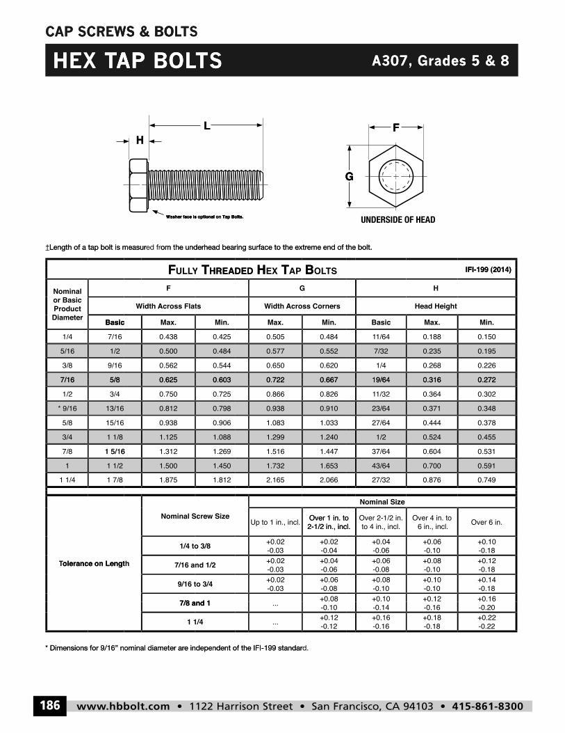
CAP SCREWS & BOLTS
HL
Washer face is optional on Tap Bolts.
G
F
HEX TAP BOLTS A307, Grades 5 & 8
CAP SCREWS & BOL
TS WS & BOL LTS
AP THEX
TS
HL
BOLLTSAP
ades 5
F
GrA307,
8& ades 5
†Length of a tap bolt is measur†
Washer face is optional on Tap Bolts.
om the underhead bearing surface to the extred frLength of a tap bolt is measur
TF
Washer face is optional on Tap Bolts.
G
eme end of the bolt. om the underhead bearing surface to the extr
B TH
G
UNDERSIDE OF HEAD
eme end of the bolt.
IFI-199 (2014)
5/87/16
1/2
9/163/8
5/16
7/161/4
BasicDiameterProduct or Basic Nominal
0.603
HREADED TYULLYF
0.625
0.484
0.5440.562
0.500
0.4250.438
Min.Max.Basic
Flatsidth Across W
F
0.667
STOLLT BAP TEXHHREADED
0.722
0.552
0.6200.650
0.577
0.4840.505
Min.Max.
Cornersidth Across W
G
0.31619/64
0.235
0.2681/4
7/32
0.1881/641
Max.Basic
Head Height
H
0.272
IFI-199 (2014)
0.195
0.226
0.150
Min.
1 1/2
1 7/81 1/4
1
1 1/8
1 5/167/8
3/4
13/16
15/165/8
* 9/16
5/8
3/41/2
7/16
1.450
1.8121.875
1.500
1.088
1.2691.3121 5/16
1.125
0.798
0.9060.938
0.812
0.603
0.7250.750
0.625
1.653
2.0662.165
1.732
1.240
1.4471.516
1.299
0.910
1.0331.083
0.938
0.667
0.8260.866
0.722
0.700
0.87627/32
43/64
0.524
0.60437/64
1/2
0.371
0.44427/64
23/64
0.316
0.3641/321
19/64
0.591
0.749
0.455
0.531
0.348
0.378
0.272
0.302
olerance on LengtTTolerance on Length
1/4 to 3/8
Nominal Screw Size
olerance on Length
7/8 and 1
9/16 to 3/4
7/16 and 1/2
+0.02-0.03+0.02
2-1/2 in., incl.Over 1 in. to Up to 1 in., incl.
+0.08-0.08+0.06
-0.03+0.02
-0.06+0.04
-0.03+0.02
-0.04
6 in., incl.Over 4 in. to
to 4 in., incl.Over 2-1/2 in.
2-1/2 in., incl.Over 1 in. to
Nominal Size
+0.12+0.10-0.10+0.10
-0.10+0.08
-0.10+0.08
-0.08+0.06
-0.10+0.06
-0.06+0.04
Over 6 in.
+0.16-0.18+0.14-0.18+0.12-0.18+0.10
811
* Dimensions for 9/16” nominal diameter ar
e independent of the IFI-199 standar* Dimensions for 9/16” nominal diameter ar
1 1/4
7/8 and 1
d.e independent of the IFI-199 standar
-0.12+0.12...
-0.10...
-0.18+0.18
-0.16+0.16
-0.16-0.14
-0.22+0.22-0.20
hbbolt_pgs_161_192_17061_template_NEW_USE 2/8/16 11:13 AM Page 186
www.hbbolt.com • 1122 Harrison Street • San Francisco, CA 94103 • 415-861-8300 187
CAP SCREWS & BOLTS
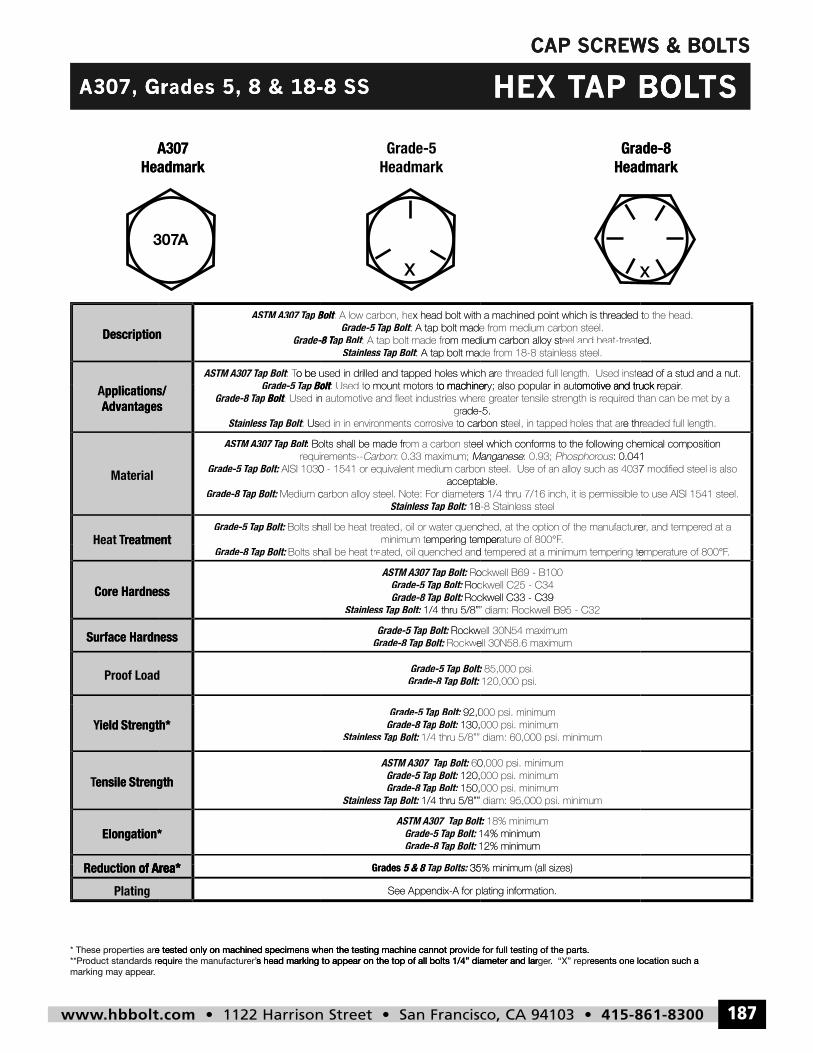
HEX TAP BOLTSA307, Grades 5, 8 & 18-8 SS
CAP SCREWS & BOL
TS WS & BOL LTS
GrA307,
A307Headmark
18-8 & 8 ades 5, Gr
A307Headmark
SS18-8
Grade-5Headmark
BOLAP THEX
Grade-8Headmark
TSBOLLTS
Grade-8Headmark
Description
t:
Description
Boltap Grade 5 T Tap o be used in drilled and tapped holes which ar: T To be used in drilled and tapped holes which arBoltap ASTM A307 T Tap
Grade-8 T
Boltap ASTM A307 T Tap
o machinerors to mount mot: Used tBoltt: o be used in drilled and tapped holes which ar
: A tap bolt made frBoltt: ap Stainless T Tap om medium carbon alloy st: A tap bolt made frBoltt: ap -8 T Tap
: A tap bolt made frBoltt: ap Grade-5 T Tap x head bolt with a machined point which is thr: A low carbon, heBoltt:
omotive and truck ry; also popular in auto machineread of a stud and a nut.eaded full length. Used inste thr readed full length. Used insto be used in drilled and tapped holes which ar
eel.om 18-8 stainless st: A tap bolt made fred.eateel and heat-tr reatom medium carbon alloy st
eel.om medium carbon st: A tap bolt made freaded tx head bolt with a machined point which is thr
epairomotive and truck read of a stud and a nut.
ed.
o the head.eaded t
reatmentHeat T
Material
Advantagespplications/ A
t:
reatmentBolt:ap Grade-5 T Tap
Advantages
Bolt:ap Grade-8 T Tap
Bolt:ap Grade-5 T Tap
Bolts shall be made fr:Boltap ASTM A307 T Tap
: Use Boltt: ap Stainless T Tap
BoltBoltap Grade-8 T Tap Boltap Grade-5 T Tap pplications/
emperempering tminimum t
18 Bolt:: ap Stainless T Tap
acceptable.
Manganese: 0.33 maximum; arbonCeel which conforms tom a carbon st Bolts shall be made fr
o carbon stosive tonments corr: Used in in envirade-5.gr
o machinerors to mount mot: Used tBoltt:
.e of 800°Faturmperratur
eeltainless st 18-8 S
acceptable.
: 0.041ousPhosphorrous: 0.93; Manganeseo the following chemical composition eel which conforms t
e threel, in tapped holes that aro carbon stade-5.
omotive and truck ry; also popular in auto machiner
: 0.041o the following chemical composition
eaded full length.e thr
.epairomotive and truck r
Proof Load
Surface Hardness
Core Hardness
Surface Hardness
Core Hardness
Bolt:ap Grade-8 T Tap
Bolt:ap Grade-8 T Tap Bolt:ap Grade-5 T Tap
Bolt:ap Grade-8 T Tap Rockwell 30N54 maximumBolt:: ap Grade-5 T Tap
1/4 thru 5/8”” diam: Rockwell B95 - C32Bolt:: ap Stainless T Tap Rockwell C33 - C39Bolt:ap Grade-8 T Tap Roc Bolt:: ap Grade-5 T Tap
Bolt:ap ASTM A307 T Tap
empering t
120,000 psi. 85,000 psi.t::
Rockwell 30N54 maximum
1/4 thru 5/8”” diam: Rockwell B95 - C32Rockwell C33 - C39 Rockwell C25 - C34
emper
of Area*Reduction
Elongation*
ensile StrengthT
ield Strength*Y
of Area*
Elongation*
ensile Strength
ield Strength*
35 B ltTT5 & 8 Grades
12% minimumBolt:ap Grade-8 T Tap 14% minimumBolt:ap Grade-5 T Tap
Bolt:ap T Tap ASTM A307
1/4 thru 5/8”” diam: 95,000 psi. minimumBolt:: ap Stainless T Tap 150, Bolt:: ap Grade-8 T Tap 120, Bolt:: ap Grade-5 T Tap
Bolt:ap T Tap ASTM A307
Bolt:ap Stainless T Tap 130, Bolt:: ap Grade-8 T Tap 92,0 Bolt:: ap Grade-5 T Tap
es) 35% minimum (all siz
12% minimum14% minimum 18% minimumt::
1/4 thru 5/8”” diam: 95,000 psi. minimum 150,000 psi. minimum 120,000 psi. minimum
130,000 psi. minimum 92,000 psi. minimum
. marking may appearequirds roduct standar**Pr
e tested only on machined specimens when the testing machine cannot properties ar* These pr
Platingof Area*Reduction
s head marking to appear on the top of all bolts 1/4” diameter and larer’e the manufacturequire tested only on machined specimens when the testing machine cannot pr
of Area*
s head marking to appear on the top of all bolts 1/4” diameter and larovide for full testing of the parts. e tested only on machined specimens when the testing machine cannot pr
See Appendix-A for plating information.
35 ap Bolts: : TTap Bolts:5 & 8 Grades
esents one location such a epr. “X” rgers head marking to appear on the top of all bolts 1/4” diameter and larovide for full testing of the parts.
See Appendix-A for plating information.
es) 35% minimum (all siz
911
esents one location such a
hbbolt_pgs_161_192_17061_template_NEW_USE 2/8/16 11:13 AM Page 187
www.hbbolt.com • 1122 Harrison Street • San Francisco, CA 94103 • 415-861-8300188
& BoltsHead & Thread
DimensionsGrades 5 & 8 Cap ScrewsCap Screws & BoltsCap Screws
ThreadHead & Grades 5 & 8 Thread Grades 5 & 8 Cap Screws & BoltsCap Screws Dimensions Cap ScrewsDimensions Cap Screws
†† ew is measurLength of a cap scr
CXEH
om the underhead bearing surface to the extred frew is measur
SWERC SPA C
eme end of the scrom the underhead bearing surface to the extr . eweme end of the scr
B18.2.1-1996ASME
0.2500
0.31250.31255/16
0.25001/4
Max
DiameterBody
E
DiameterBasic Product
Nominal or
0.428
0.4890.5001/20.3065
0.4387/160.2450
MinMaxBasicMin
Across Flatsidth W DiameterBody
FE
0.163
10.2113/640.5570.577
5/320.4880.505
MaxBasicMinMax
Head HeightCornersAcross idth W
HG
0.750
0.8750.1400.195
0.1060.150
RefMinMin
LengthsFor Screw
Lengths For Screw
Thread Length
Heightrenching WHead Height
TLJ
0.250
0.2781.125
1.000
MaxRef
> 6 in.Lengths
For Screw LengthThread ransition T
Thread Length
YB18.2.1-1996
0.5000
0.56250.56259/16
0.50001/2
0.3750
0.43750.43757/16
0.37503/8
0.87500.87507/8
0.6250
0.75000.75003/4
0.62505/8
0.736
0.7980.81213/160.5545
0.7503/40.4930
0.551
0.6120.6255/80.4305
0.5629/160.3690
1.2851.3121-5/160.8660
0.922
1.1001.1251-1/80.7410
0.93815/160.6170
0.323
0.9100.938
5/160.8400.866
0.243
0.2919/320.6980.722
15/640.6280.650
0.56335/641.4651.516
0.403
0.48315/321.2541.299
25/641.0511.083
0.37123/64
1.2500.2150.302
1.000
1.1250.1950.272
0.1600.226
2.0000.3780.531
1.500
1.7500.3240.455
0.2690.378
1.3750.2500.348
0.3851.500
0.312
0.3571.375
1.250
0.5562.250
0.455
0.5002.000
1.750
0.4171.625
1.50001.50001-1/2
1.1250
1.25001.25001-1/4
1.12501-1/8
1.00001.00001
2.175
Up to 1 in., incl.SizeNominal Screw
2.2502-1/41.4880
1.631
1.8121.8751-7/81.2390
1.6881/161-11401.1
1.4691.5001-1/20.9900
0.974
Over 2-1/2 in. to Over 1 in. to Up to 1 in., incl.
Nominal Screw Length
1-5/162.4802.598
0.718
0.81325/322.0662.165
1/1611.8591.949
0.62739/641.6751.732
3.250
Longer than 6 in.Over 4 in. to 6 in., incl.Over 2-1/2 in. to
Nominal Screw Length
0.6400.902
2.500
2.7500.5300.749
0.4610.658
2.2500.4160.591
0.833
Longer than 6 in.
3.500
0.714
0.7143.000
2.750
0.6252.500
90
olerance on LengTTolerance on Length -0.031/4 to 3/8
Up to 1 in., incl.
olerance on Length
....1-1/8 to 1-1/2
....7/8 and 1-0.039/16 to 3/4-0.037/16 and 1/2
-0.06-0.04-0.03
4 in., incl.2-1/2 in., incl.Up to 1 in., incl.
-0.16-0.12....-0.14-0.10....
-0.10-0.08-0.03
-0.08-0.06-0.03
-0.06
Longer than 6 in.Over 4 in. to 6 in., incl.4 in., incl.
-0.18-0.16-0.16-0.14
-0.10-0.10
-0.10-0.08
-0.10
Longer than 6 in.
-0.22-0.20
-0.18
-0.18
-0.18
hbbolt_pgs_161_192_17061_template_NEW_USE 2/8/16 11:13 AM Page 188
www.hbbolt.com • 1122 Harrison Street • San Francisco, CA 94103 • 415-861-8300 189
Bolts & Mechanical &
Performance DataGrades 5 & 8 Cap Screws
x
x
Grades 5 & 8
Grades 5 & 8 Mechanical &
Mechanical & Bolts & Cap Screws Cap Screws Cap Screws
Description
Cap Screws erformance DataP
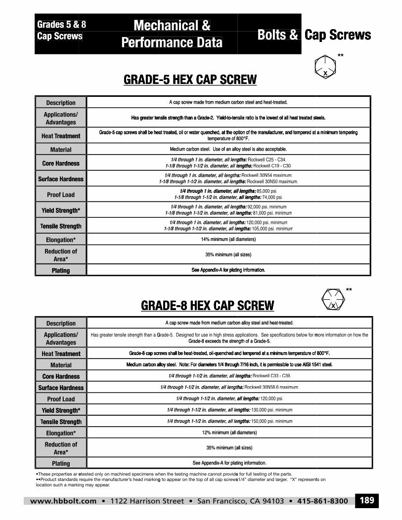
GRADE-5 HEX CAP SCREW
erformance Data
A cap screw made from medium carbon steel and heat-treated.
GRADE-5 HEX CAP SCREW
Bolts & Cap Screws
A cap screw made from medium carbon steel and heat-treated.
GRADE-5 HEX CAP SCREW
Cap Screws
x
**
Surface Hardness
Core Hardness
Material
reatmentTHeat
Advantagespplications/ A
Surface Hardness
Core Hardness
reatmentGrade-5 cap screws shall be heat treated, oil or water quenched, at the option of the manufacturer, and tempered at a minimum tempering
Has greater tensile strength than a Grade-2. Yield-to-tensile ratio is the lowest of all heat treated steels.
1/4 through 1 in. diameter, all lengths:
1-1/8 through 1-1/2 in. diameter, all lengths:1/4 through 1 in. diameter, all lengths:
1-1/8 through 1-1/2 in. diameter, all lengths:1/4 through 1 in. diameter, all lengths:
Medium carbon steel. Use of an alloy steel is also acceptable.
temperature of 800°F.Grade-5 cap screws shall be heat treated, oil or water quenched, at the option of the manufacturer, and tempered at a minimum tempering
Has greater tensile strength than a Grade-2. Yield-to-tensile ratio is the lowest of all heat treated steels.
85 000 i ll lengths:
Rockwell 30N50 maximum. gths: : Rockwell 30N54 maximum. s: :
Rockwell C19 - C30. lengths: : Rockwell C25 - C34. gths: :
Medium carbon steel. Use of an alloy steel is also acceptable.
temperature of 800°F.Grade-5 cap screws shall be heat treated, oil or water quenched, at the option of the manufacturer, and tempered at a minimum tempering
Has greater tensile strength than a Grade-2. Yield-to-tensile ratio is the lowest of all heat treated steels.
Grade-5 cap screws shall be heat treated, oil or water quenched, at the option of the manufacturer, and tempered at a minimum tempering
Has greater tensile strength than a Grade-2. Yield-to-tensile ratio is the lowest of all heat treated steels.
Plating
Area*Reduction of
Elongation*
ensile StrengthTTensile Strength
ield Strength*Y
Proof Load
ensile Strength
ield Strength*
See Appendix-A for plating information.
35% minimum (all sizes)
14% minimum (all diameters)
1-1/8 through 1-1/2 in. diameter, all lengths:1/4 through 1 in. diameter, all lengths:
1-1/8 through 1-1/2 in. diameter, all lengths:1/4 through 1 in. diameter, all lengths:
1-1/8 through 1-1/2 in. diameter, all lengths:1/4 through 1 in. diameter, all lengths:
See Appendix-A for plating information.
35% minimum (all sizes)
14% minimum (all diameters)
105,000 psi. minimum engths: : 120,000 psi. minimum gths: :
81,000 psi. minimum engths: : 92,000 psi. minimum gths: :
74,000 psi. all lengths: : 85,000 psi. ll lengths: :
Plating
Description
Advantagespplications/ A
GRADE-8 HEX CAP SCREW
See Appendix-A for plating information.
Grade-8 exceeds the strength of a Grade-5.
A cap screw made from medium carbon alloy steel and heat-treated.
GRADE-8 HEX CAP SCREW
See Appendix-A for plating information.
Grade-8 exceeds the strength of a Grade-5.
A cap screw made from medium carbon alloy steel and heat-treated.
GRADE-8 HEX CAP SCREW
x**
ensile StrengthTTensile Strength
ield Strength*Y
Proof Load
Surface Hardness
Core Hardness
Material
reatmentTHeat
ensile Strength
ield Strength*
Surface Hardness
Core Hardness
reatment
Medium carbon alloy steel. Note: For diameters 1/4 through 7/16 inch, it is permissible to use AISI 1541 steel.
Grade-8 cap screws shall be heat-treated, oil-quenched and tempered at a minimum temperature of 800°F.
1/4 through 1-1/2 in. diameter, all lengths:
1/4 through 1-1/2 in. diameter, all lengths:
1/4 through 1-1/2 in. diameter, all lengths:
1/4 through 1-1/2 in. diameter, all lengths:
1/4 through 1-1/2 in. diameter, all lengths:
Medium carbon alloy steel. Note: For diameters 1/4 through 7/16 inch, it is permissible to use AISI 1541 steel.
Grade-8 cap screws shall be heat-treated, oil-quenched and tempered at a minimum temperature of 800°F.
150,000 psi. minimum engths: :
130,000 psi. minimum engths: :
120,000 psi. all lengths: :
Rockwell 30N58.6 maximum. ths: :
Rockwell C33 - C39. engths: :
Medium carbon alloy steel. Note: For diameters 1/4 through 7/16 inch, it is permissible to use AISI 1541 steel.
Grade-8 cap screws shall be heat-treated, oil-quenched and tempered at a minimum temperature of 800°F.
Medium carbon alloy steel. Note: For diameters 1/4 through 7/16 inch, it is permissible to use AISI 1541 steel.
Grade-8 cap screws shall be heat-treated, oil-quenched and tempered at a minimum temperature of 800°F.
Plating
Area*Reduction of
Elongation*
See Appendix-A for plating information.
35% minimum (all sizes)
12% minimum (all diameters)
See Appendix-A for plating information.
35% minimum (all sizes)
12% minimum (all diameters)
91
hbbolt_pgs_161_192_17061_template_NEW_USE 2/8/16 11:13 AM Page 189
www.hbbolt.com • 1122 Harrison Street • San Francisco, CA 94103 • 415-861-8300190
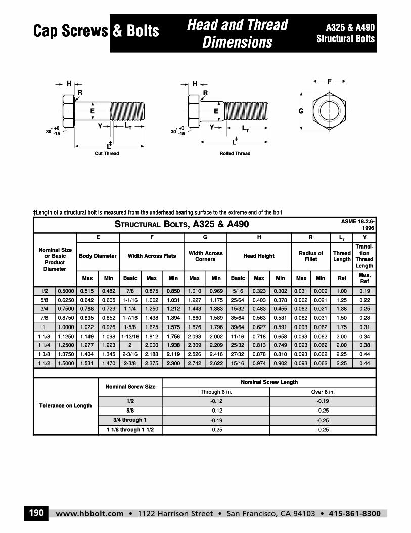
Cap Screws & Bolts Head and ThreadDimensions
A325 & A490Structural Bolts
STRUCTURAL BOLTS, A325 & A490 ASME 18.2.6-1996
Nominal Sizeor BasicProductDiameter
E F G H R LT
Y
Body Diameter Width Across Flats Width AcrossCorners
Head Height Radius ofFillet
ThreadLength
Transi-tion
ThreadLength
Max Min Basic Max Min Max Min Basic Max Min Max Min RefMax,Ref
1/2 0.5000 0.515 0.482 7/8 0.875 0.850 1.010 0.969 5/16 0.323 0.302 0.031 0.009 1.00 0.19
5/8 0.6250 0.642 0.605 1-1/16 1.062 1.031 1.227 1.175 25/64 0.403 0.378 0.062 0.021 1.25 0.22
3/4 0.7500 0.768 0.729 1-1/4 1.250 1.212 1.443 1.383 15/32 0.483 0.455 0.062 0.021 1.38 0.25
7/8 0.8750 0.895 0.852 1-7/16 1.438 1.394 1.660 1.589 35/64 0.563 0.531 0.062 0.031 1.50 0.28
1 1.0000 1.022 0.976 1-5/8 1.625 1.575 1.876 1.796 39/64 0.627 0.591 0.093 0.062 1.75 0.31
1 1/8 1.1250 1.149 1.098 1-13/16 1.812 1.756 2.093 2.002 11/16 0.718 0.658 0.093 0.062 2.00 0.34
1 1/4 1.2500 1.277 1.223 2 2.000 1.938 2.309 2.209 25/32 0.813 0.749 0.093 0.062 2.00 0.38
1 3/8 1.3750 1.404 1.345 2-3/16 2.188 2.119 2.526 2.416 27/32 0.878 0.810 0.093 0.062 2.25 0.44
1 1/2 1.5000 1.531 1.470 2-3/8 2.375 2.300 2.742 2.622 15/16 0.974 0.902 0.093 0.062 2.25 0.44
Tolerance on Length
Nominal Screw SizeNominal Screw Length
Through 6 in. Over 6 in.
1/2 -0.12 -0.19
5/8 -0.12 -0.25
3/4 through 1 -0.19 -0.25
1 1/8 through 1 1/2 -0.25 -0.25
H
LT
L
E G
F
RR
Cut Thread Rolled Thread
H
LT
L
E
Y30
o +0-15
Y30
o +0-15
Cap Screws & BoltsCap Screws Head and Thread A325 & A490Head and Thread A325 & A490Cap Screws
RH
& BoltsCap Screws
EE
Dimensions
H
E
R
Structural BoltsDimensions
G
F
Structural Bolts
-15+0o
30
‡L
Cut Thread
TL
L‡
Y
‡L
TL
L‡
E
Rolled Thread
Y-15+0o
30
G
‡Length of a structural bolt is measured from the underhead bearing sur
Body Diameter
DiameterProductor Basic
Nominal Size
‡Length of a structural bolt is measured from the underhead bearing sur
Width Across FlatsBody Diameter
E F
OLTSBTRUCTURALSface to the extreme end of the bolt.‡Length of a structural bolt is measured from the underhead bearing sur
Head HeightCorners
Width AcrossWidth Across Flats
G
A490&A325,OLTS
face to the extreme end of the bolt.
FilletRadius ofHead Height
RH
Max,
LengthThread
tionTransi-
LengthThread
YT
L
1996ASME 18.2.6-
Max
1/2 0.5000 0.515
0.6420.62505/8
3/4 0.7500 0.768
0.8950.87507/8
1 1.0000 1.022
1.1491.12501 1/8
1 1/4 1.2500 1.277
1.4041.37501 3/8
MinMaxBasicMinMax
0.515 0.482 7/8 0.875 0.850
1.0311.0621-1/160.6050.642
0.768 0.729 1-1/4 1.250 1.212
1.3941.4381-7/160.8520.895
1.022 0.976 1-5/8 1.625 1.575
1.7561.8121-13/161.0981.149
1.277 1.223 2 2.000 1.938
2.1192.1882-3/161.3451.404
BasicMinMaxMin
0.850 1.010 0.969 5/16
25/641.1751.2271.031
1.212 1.443 1.383 15/32
35/641.5891.6601.394
1.575 1.876 1.796 39/64
11/162.0022.0931.756
1.938 2.309 2.209 25/32
27/322.4162.5262.119
MinMaxMinMax
0.323 0.302 0.031 0.009
0.0210.0620.3780.403
0.483 0.455 0.062 0.021
0.0310.0620.5310.563
0.627 0.591 0.093 0.062
0.0620.0930.6580.718
0.813 0.749 0.093 0.062
0.0620.0930.8100.878
RefMax,
Ref
1.00 0.19
0.221.25
1.38 0.25
0.281.50
1.75 0.31
0.342.00
2.00 0.38
0.442.25
1 1/2 1.5000 1.531
Tolerance on Length
1.531 1.470 2-3/8 2.375 2.300
Nominal Screw Size
Tolerance on Length1/2
5/8
3/4 through 1
1 1/8 through 1 1/2
2.300 2.742 2.622 15/16
Through 6 in.
Nominal Screw Length
-0.12
-0.12
-0.19
-0.25
0.974 0.902 0.093 0.062
Over 6 in.
Nominal Screw Length
-0.19
-0.25
-0.25
-0.25
2.25 0.44
Over 6 in.
hbbolt_pgs_161_192_17061_template_NEW_USE 2/8/16 11:13 AM Page 190
www.hbbolt.com • 1122 Harrison Street • San Francisco, CA 94103 • 415-861-8300 191
Bolts & Cap ScrewsMechanical &Performance Data
A325 & A490Structural Bolts
A325x
A325x
A490x
A490x
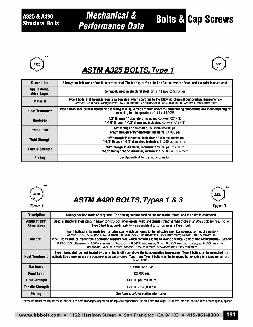
Description A heavy hex bolt made of medium carbon steel. The bearing surface shall be flat and washer faced, and the point is chamfered.
Applications/Advantages
Commonly used in structural steel joints in heavy construction.
Material Type 1 bolts shall be made from a carbon steel which conforms to the following chemical composition requirements--Carbon: 0.25-0.58%; Manganese: 0.57% minimum; Phosphorus: 0.048% maximum; Sulfur: 0.058% maximum
Heat Treatment Type 1 bolts shall be heat treated by quenching in a liquid medium from above the austenitizing temperature and then tempering byreheating to a temperature of at least 800°F.
Hardness 1/2" through 1" diameter, inclusive: Rockwell C24 - 351-1/8" through 1-1/2" diameter, inclusive: Rockwell C19 - 31
Proof Load 1/2" through 1" diameter, inclusive: 85,000 psi.1-1/8" through 1-1/2" diameter, inclusive: 74,000 psi.
Yield Strength 1/2" through 1" diameter, inclusive: 92,000 psi. minimum1-1/8" through 1-1/2" diameter, inclusive: 81,000 psi. minimum
Tensile Strength 1/2" through 1" diameter, inclusive: 120,000 psi. minimum1-1/8" through 1-1/2" diameter, inclusive: 105,000 psi. minimum
Plating See Appendix-A for plating information.
Description A heavy hex bolt made of alloy steel. The bearing surface shall be flat and washer-faced, and the point is chamfered.
Applications/Advantages
Used in structural steel joints in heavy construction when greater yield and tensile strengths than those of an A325 bolt are required. AType 3 bolt is approximately twice as resistant to corrosion as a Type 1 bolt.
Material
Type 1 bolts shall be made from an alloy steel which conforms to the following chemical composition requirements--Carbon: 0.28-0.50% (for 1-1/2" diameter: 0.33-0.55%); Phosphorus: 0.045% maximum; Sulfur: 0.045% maximum.
Type 3 bolts shall be made from a corrosion resistant steel which conforms to the following chemical composition requirements-- Carbon:0.19-0.55%; Manganese: 0.37% minimum; Phosphorus: 0.045% maximum; Sulfur: 0.055% maximum; Copper: 0.63% maximum;
Chromium: 0.42% minimum; Nickel: 0.17% minimum; Molybdenum: 0.14% minimum.
Heat TreatmentType 1 bolts shall be heat treated by quenching in oil from above the transformation temperature. Type 3 bolts shall be quenched in a
suitable liquid from above the transformation temperature. Type 1 and Type 3 bolts shall be tempered by reheating to a temperature of atleast 800°F.
Hardness Rockwell C33 - 38
Proof Load 120,000 psi.
Yield Strength 130,000 psi. minimum
Tensile Strength 150,000 - 170,000 psi.
Plating See Appendix-A for plating information.
A325 & A490
Mechanical &A325 & A490
Mechanical &
Cap Bolts &
Cap Screws
Structural Bolts
xA325
**
Performance DataStructural Bolts
ASTM A325 BOL
Performance Data
ASTM A325 BOLTS,
Cap Bolts &
Type 1ype 1T
Cap Screws
xA325
**
Description
AdvantagesApplications/
Material
Heat Treatment
Hardness
ASTM A325 BOL
A heavy hex bolt made of medium carbon steel. The bearing surface shall be flat and washer faced, and the point is chamfered.
0.25-0.58%;Carbon:Type 1 bolts shall be made from a carbon steel which conforms to the following chemical composition requirements--
Heat Treatment Type 1 bolts shall be heat treated by quenching in a liquid medium from above the austenitizing temperature and then tempering
ASTM A325 BOL ,TS,
A heavy hex bolt made of medium carbon steel. The bearing surface shall be flat and washer faced, and the point is chamfered.
Commonly used in structural steel joints in heavy construction.
Phosphorus:0.57% minimum;Manganese:0.25-0.58%;Type 1 bolts shall be made from a carbon steel which conforms to the following chemical composition requirements--
reheating to a temperature of at least 800Type 1 bolts shall be heat treated by quenching in a liquid medium from above the austenitizing temperature and then tempering
1/2" through 1" diameter, inclusive:
,, Type 1yp ype 1T
A heavy hex bolt made of medium carbon steel. The bearing surface shall be flat and washer faced, and the point is chamfered.
Commonly used in structural steel joints in heavy construction.
0.058% maximumSulfur: 0.048% maximum;horus:: Type 1 bolts shall be made from a carbon steel which conforms to the following chemical composition requirements--
F.°reheating to a temperature of at least 800Type 1 bolts shall be heat treated by quenching in a liquid medium from above the austenitizing temperature and then tempering
Rockwell C24 - 351/2" through 1" diameter, inclusive:
A heavy hex bolt made of medium carbon steel. The bearing surface shall be flat and washer faced, and the point is chamfered.
0.058% maximumType 1 bolts shall be made from a carbon steel which conforms to the following chemical composition requirements--
byType 1 bolts shall be heat treated by quenching in a liquid medium from above the austenitizing temperature and then tempering
Hardness
Proof Load
Yield Strength
Tensile Strength
Plating
Yield Strength
Tensile Strength
1-1/8" through 1-1/2" diameter, inclusive:1/2" through 1" diameter, inclusive:
1-1/8" through 1-1/2" diameter, inclusive:1/2" through 1" diameter, inclusive:
1-1/8" through 1-1/2" diameter, inclusive1/2" through 1" diameter, inclusive:
1-1/8" through 1-1/2" diameter, inclusive:1/2" through 1" diameter, inclusive:
See Appendix-A for plating information.
Rockwell C19 - 311-1/8" through 1-1/2" diameter, inclusive: Rockwell C24 - 351/2" through 1" diameter, inclusive:
74,000 psi.1-1/8" through 1-1/2" diameter, inclusive: 85,000 psi.1/2" through 1" diameter, inclusive:
: 81,000 psi. minimum1-1/8" through 1-1/2" diameter, inclusive 92,000 psi. minimum1/2" through 1" diameter, inclusive:
105,000 psi. minimum1-1/8" through 1-1/2" diameter, inclusive:120,000 psi. minimum1/2" through 1" diameter, inclusive:
See Appendix-A for plating information.
xA490
**
ype 1TType 1
Description
ASTM A490 BOL
A heavy hex bolt made of alloy steel. The bearing surface shall be flat and washer-faced, and the point is chamfered.
ASTM A490 BOL ,TS, Types 1 & 3y y T
A heavy hex bolt made of alloy steel. The bearing surface shall be flat and washer-faced, and the point is chamfered.
yp ypes 1 & 3
A heavy hex bolt made of alloy steel. The bearing surface shall be flat and washer-faced, and the point is chamfered.
xA490
**
ype 3TType 3
A heavy hex bolt made of alloy steel. The bearing surface shall be flat and washer-faced, and the point is chamfered.
AdvantagesApplications/
Material
Heat Treatment
Hardness
Type 3 bolt is approximately twice as resistant to corrosion as a Type 1 bolt.Used in structural steel joints in heavy construction when greater yield and tensile strengths than those of an A325 bolt are r
Chromium:0.37% minimum;Manganese:0.19-0.55%;
bolts shall be made from a corrosion resistant steel which conforms to the following chemical composition requirements--3Type 0.28-0.50% (for 1-1/2" diameter: 0.33-0.55%);Carbon:
bolts shall be made from an alloy steel which conforms to the following chemical composition requirements--1Type
suitable liquid from above the transformation temperature. Type 1 and Type 3 bolts shall be tempered by reheating to a temperatType 1 bolts shall be heat treated by quenching in oil from above the transformation temperature. Type 3 bolts shall be quenche
Type 3 bolt is approximately twice as resistant to corrosion as a Type 1 bolt.Used in structural steel joints in heavy construction when greater yield and tensile strengths than those of an A325 bolt are r
0.17% minimum;Nickel:0.42% minimum;0.045% maximum;Phosphorus:0.37% minimum;
bolts shall be made from a corrosion resistant steel which conforms to the following chemical composition requirements--Phosphorus:0.28-0.50% (for 1-1/2" diameter: 0.33-0.55%);
bolts shall be made from an alloy steel which conforms to the following chemical composition requirements--
F.°least 800suitable liquid from above the transformation temperature. Type 1 and Type 3 bolts shall be tempered by reheating to a temperat
Type 1 bolts shall be heat treated by quenching in oil from above the transformation temperature. Type 3 bolts shall be quenche
Rockwell C33 - 38
Type 3 bolt is approximately twice as resistant to corrosion as a Type 1 bolt.Used in structural steel joints in heavy construction when greater yield and tensile strengths than those of an A325 bolt are r
0.14% minimum.Molybdenum:0.17% minimum;Copper: 0.055% maximum;Sulfur:: 0.045% maximum;
bolts shall be made from a corrosion resistant steel which conforms to the following chemical composition requirements--0.045% maximum.Sulfur:0.045% maximum;Phosphorus:
bolts shall be made from an alloy steel which conforms to the following chemical composition requirements--
suitable liquid from above the transformation temperature. Type 1 and Type 3 bolts shall be tempered by reheating to a temperatType 1 bolts shall be heat treated by quenching in oil from above the transformation temperature. Type 3 bolts shall be quenche
Rockwell C33 - 38
equired. AUsed in structural steel joints in heavy construction when greater yield and tensile strengths than those of an A325 bolt are r
0.63% maximum;Copper:Carbon: bolts shall be made from a corrosion resistant steel which conforms to the following chemical composition requirements--
0.045% maximum. bolts shall be made from an alloy steel which conforms to the following chemical composition requirements--
ure of atsuitable liquid from above the transformation temperature. Type 1 and Type 3 bolts shall be tempered by reheating to a temperatd in aType 1 bolts shall be heat treated by quenching in oil from above the transformation temperature. Type 3 bolts shall be quenche
**Product standards require the manufacturer’
Proof Load
Yield Strength
Tensile Strength
Plating
s head marking to appear on the top of all cap screws 1/4” diameter and larger**Product standards require the manufacturer’
s head marking to appear on the top of all cap screws 1/4” diameter and larger
120,000 psi.
130,000 psi. minimum
150,000 - 170,000 psi.
See Appendix-A for plating information.
” represents one location such a marking may appear. “Xs head marking to appear on the top of all cap screws 1/4” diameter and larger
130,000 psi. minimum
150,000 - 170,000 psi.
See Appendix-A for plating information.
.” represents one location such a marking may appear
hbbolt_pgs_161_192_17061_template_NEW_USE 2/8/16 11:13 AM Page 191
www.hbbolt.com • 1122 Harrison Street • San Francisco, CA 94103 • 415-861-8300192
Bolts & Cap Screws
F
G
SH
E
GIMLET POINT
L
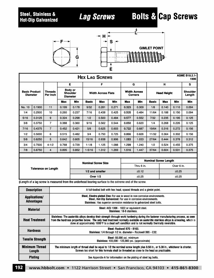
Description A full-bodied bolt with hex head, spaced threads and a gimlet point.
Applications/Advantages
Steel, Electro-plated Zinc: For use in wood in non-corrosive environments.Steel, Hot-Dip Galvanized: For use in corrosive environments.
Stainless: Has superior corrosion resistance to galvanized steel bolts.
Material Steel: AISI 1006 - 1022 or equivalent steel.Stainless: 18-8 stainless.
Heat TreatmentStainless: The austenitic alloys develop their strength through work hardening during the fastener manufacturing process, as seenfrom the hardness properties below. The only heat treatment normally available on austenitic stainless alloys is annealing, which is
done at approximately 1900°F to a dead soft condition and is not normally thermally reversible.
Hardness Steel: Rockwell B70 - B100.Stainless: 1/4 through 1/2 in. diameter-- Rockwell B95 - C32.
Tensile Strength Steel: 60,000 psi. minimumStainless: 100,000 - 125,000 psi. (approximate)
Minimum ThreadLength
The minimum length of thread shall be equal to 1/2 the nominal screw length plus 0.50 in., or 5.00 in., whichever is shorter.Screws too short for this formula shall be threaded as close to the head as practicable.
Plating See Appendix-A for information on the plating of steel lag bolts.
Lag ScrewsSteel, Stainless &Hot-Dip Galvanized
HEX LAG SCREWSASME B18.2.1-
1996
Basic ProductDiameter
ThreadsPer Inch
E F G H S
Body orShoulderDiameter
Width Across Flats Width AcrossCorners
Head Height ShoulderLength
Max Min Basic Max Min Max Min Basic Max Min Min
No. 10 0.1900 11 0.199 0.178 9/32 0.281 0.271 0.323 0.309 1/8 0.140 0.110 0.094
1/4 0.2500 10 0.260 0.237 7/16 0.438 0.425 0.505 0.484 11/64 0.188 0.150 0.094
5/16 0.3125 9 0.324 0.298 1/2 0.500 0.484 0.577 0.552 7/32 0.235 0.195 0.125
3/8 0.3750 7 0.388 0.360 9/16 0.562 0.544 0.650 0.620 1/4 0.268 0.226 0.125
7/16 0.4375 7 0.452 0.421 5/8 0.625 0.603 0.722 0.687 19/64 0.316 0.272 0.156
1/2 0.5000 6 0.515 0.482 3/4 0.750 0.725 0.866 0.826 11/32 0.364 0.302 0.156
5/8 0.6250 5 0.642 0.605 15/16 0.938 0.906 1.083 1.033 27/64 0.444 0.378 0.312
3/4 0.7500 4-1/2 0.768 0.729 1-1/8 1.125 1.088 1.299 1.240 1/2 0.524 0.455 0.375
7/8 0.8750 4 0.895 0.852 1-5/16 1.312 1.269 1.516 1.447 37/64 0.604 0.531 0.375
Tolerance on Length
Nominal Screw SizeNominal Screw Length
Thru 6 in. Over 6 in.
1/2 and smaller ±0.12 ±0.25
Over 1/2 ±0.25 ±0.25
Steel, Stainless &Steel, Stainless & Lag ScrewsLag Screws Cap Bolts & Cap ScrewsHot-Dip GalvanizedHot-Dip Galvanized
F
G
Lag ScrewsLag Screws
SH
Cap Bolts &
GIMLET POINT
LL‡‡L
Cap Screws
DiameterBasic Product
MinxaM
DiameterShoulderBody or
E
Per InchThreads
EXH
E
MMinxaMBasic
Width AcrossWidth Across Flats
E F
CREWSSAGLEX
xaMBasicMinxaM
Head HeightCorners
Width Across
HG
MinMin
LengthShoulderHead Height
S
1996ASME B18.2.1-
No. 10 0.1900
0.25001/4
5/16 0.3125
0.37503/8
7/16 0.4375
0.50001/2
5/8 0.6250
MinxaM
11 0.199 0.178
0.2370.26010
9 0.324 0.298
0.3600.3887
7 0.452 0.421
0.4820.5156
5 0.642 0.605
MMinxaMBasic
9/32 0.281 0.271 0.323
0.5050.4250.4387/16
1/2 0.500 0.484 0.577
0.6500.5440.5629/16
5/8 0.625 0.603 0.722
0.8660.7250.7503/4
15/16 0.938 0.906 1.083
xaMBasicMinxaM
0.323 0.309 1/8 0.140
0.18811/640.4840.505
0.577 0.552 7/32 0.235
0.2681/40.6200.650
0.722 0.687 19/64 0.316
0.36411/320.8260.866
1.083 1.033 27/64 0.444
MinMin
0.110 0.094
0.0940.150
0.195 0.125
0.1250.226
0.272 0.156
0.1560.302
0.378 0.312
‡Length of a lag screw is measured from the underhead bearing sur
0.75003/4
7/8 0.8750
Tolerance on Length
‡Length of a lag screw is measured from the underhead bearing sur
0.7290.7684-1/2
4 0.895 0.852
Nominal Screw Size
Tolerance on Length
face to the extreme end of the screw‡Length of a lag screw is measured from the underhead bearing sur
1.2991.0881.1251-1/8
1-5/16 1.312 1.269 1.516
Nominal Screw Size
1/2 and smaller
Over 1/2
.face to the extreme end of the screw
0.5241/21.2401.299
1.516 1.447 37/64 0.604
Thru 6 in.
Nominal Screw Length
0.12±
0.25±
0.3750.455
0.531 0.375
in.6 Over
Nominal Screw Length
0.25
0.25±
±
Description
AdvantagesApplications/
Material
Heat Treatment
Applications/ Steel, Electro-plated Zinc:
Heat Treatmentdone at approximately 1900
from the hardness properties below. The only heat treatment normally available on austenitic stainless alloys is annealing, whThe austenitic alloys develop their strength through work hardening during the fastener manufacturing process, as seenStainless:
A full-bodied bolt with hex head, spaced threads and a gimlet point.
Has superior corrosion resistance to galvanized steel bolts.Stainless: For use in corrosive environments.Steel, Hot-Dip Galvanized:
For use in wood in non-corrosive environments.Steel, Electro-plated Zinc:
18-8 stainless.Stainless: AISI 1006 - 1022 or equivalent steel.Steel:
F to a dead soft condition and is not normally thermally reversible.°done at approximately 1900from the hardness properties below. The only heat treatment normally available on austenitic stainless alloys is annealing, wh
The austenitic alloys develop their strength through work hardening during the fastener manufacturing process, as seen
Rockwell B70 - B100.Steel:
A full-bodied bolt with hex head, spaced threads and a gimlet point.
Has superior corrosion resistance to galvanized steel bolts. For use in corrosive environments.
For use in wood in non-corrosive environments.
18-8 stainless. AISI 1006 - 1022 or equivalent steel.
F to a dead soft condition and is not normally thermally reversible.from the hardness properties below. The only heat treatment normally available on austenitic stainless alloys is annealing, wh
The austenitic alloys develop their strength through work hardening during the fastener manufacturing process, as seen
Rockwell B70 - B100.
F to a dead soft condition and is not normally thermally reversible.ich isfrom the hardness properties below. The only heat treatment normally available on austenitic stainless alloys is annealing, wh
The austenitic alloys develop their strength through work hardening during the fastener manufacturing process, as seen
Hardness
Tensile Strength
LengthMinimum Thread
Plating
Tensile Strength
Minimum ThreadScrews too short for this formula shall be threaded as close to the head as practicable.
The minimum length of thread shall be equal to 1/2 the nominal screw length plus 0.50 in., or 5.00 in., whichever is shorter.
1/4 through 1/2 in. diameter-- Rockwell B95 - C32.Stainless: Rockwell B70 - B100.Steel:
100,000 - 125,000 psi. (approximate)Stainless: 60,000 psi. minimumSteel:
Screws too short for this formula shall be threaded as close to the head as practicable.The minimum length of thread shall be equal to 1/2 the nominal screw length plus 0.50 in., or 5.00 in., whichever is shorter.
See Appendix-A for information on the plating of steel lag bolts.
1/4 through 1/2 in. diameter-- Rockwell B95 - C32. Rockwell B70 - B100.
100,000 - 125,000 psi. (approximate) 60,000 psi. minimum
Screws too short for this formula shall be threaded as close to the head as practicable.The minimum length of thread shall be equal to 1/2 the nominal screw length plus 0.50 in., or 5.00 in., whichever is shorter.
See Appendix-A for information on the plating of steel lag bolts.
Screws too short for this formula shall be threaded as close to the head as practicable.The minimum length of thread shall be equal to 1/2 the nominal screw length plus 0.50 in., or 5.00 in., whichever is shorter.
hbbolt_pgs_161_192_17061_template_NEW_USE 2/8/16 11:13 AM Page 192
www.hbbolt.com • 1122 Harrison Street • San Francisco, CA 94103 • 415-861-8300 193
& Bolts
HP
A
O
E
L
x
Carriage BoltsRound head, Square Neck
Low Carbon &Hot-Dip Galvanized
Cap Screws
& BoltsCap Screws
Carriage Bolts
w Carbon &LoCarriage Bolts
w Carbon &
Cap Screws
& BoltsCap Screws Round head,H
P
Square Neck
L
E
Round head,Carriage Bolts
Galvanized
A
O
Hot-Dip Square Neck
Galvanized
0.2500
C
0.31251/4
0.190010
0.1380
Basic Bolt Diameter
0.594
OR - STLTO BEGAIRRAC
0.7190.2980.3240.237
0.5000.2250.1820.199
0.3130.3280.1570.173
0.1080.122MaxMinMaxHead DiameterBody Diameter
E
,
0.125
NERAUQS, DAE HDNU
0.145
0.0940.1250.149
140.1
0.0710.0830.1020.298
0.278MinMaxMin
Head HeightHead DiameterHA
KCE
0.1870.3070.3240.2450.125
0.1250.1350.1970.2150.125
0.1850.1990.094
0.0940.1080.1550.083
0.1350.071MaxMinMaxMinSquare DepthidthSquare W
OASME B18.5-1990
0.1250.187
0.0940.1050.135
0.1250.0780.108
0.094MinMax
Square DepthP
ASME B18.5-1990
0.50005/81/2
0.37500.4375
3/8
0.7500
0.3125
olerance TTolerance on Length
3/4
1.0940.4830.515
0.8440.4210.452
0.388
1.594
0.7190.2980.324
Nominal Bolt Size
olerance on Length
0.7291.344
0.2500.2701.032
0.1880.2190.2390.907
0.2080.782
0.375
0.03+0.02 -No. 6 thru 3/8
Up to 1 in., incl.Nominal Bolt Size
0.3130.3441.219
, , ,
0.2810.4920.5150.250
0.2190.2500.4310.4520.219
0.3880.1880.1870.3070.324
-0.10+0.04
-0.04+0.02
0.03+0.02 -
in., incl.to 4 in., incl.Over 2-1/2 in.
2-1/2 in., incl.Over 1 in. to Up to 1 in., incl.
Nominal Bolt Length
0.7410.3750.3440.313
0.2500.281
0.1880.2190.250
0.219
0.375
0.187
-0.18+0.10
-0.10
incl.
0.3130.344
olerance TTolerance on Length
Description
†† ew is measurLength of a cap scr
LOW CARBON & HOT
olerance on Length
Low Carbon Steel Carriage:
om the underhead bearing surface to the extred frew is measur
-DIP GALLOW CARBON & HOT
-0.03+0.029/16 thru 3/4-0.03+0.027/16 and 1/20.03
Low Carbon Steel Carriage:
eme end of the scrom the underhead bearing surface to the extr
ANIZED VVANIZED CARRAIGE BOLDIP GAL LV
-0.10+0.10
-0.10+0.08
-0.08-0.03+0.02
-0.10+0.08
-0.08-0.05+0.04
-0.03+0.02
-0.10-0.040.03
. eweme end of the scr
ANIZED CARRAIGE BOL
-0.18+0.14
-0.10+0.10
-0.18+0.12
-0.10+0.08
-0.18-0.10
x**
T L LT
Description
Elongation*
ensile StrengthTTensile Strength
ield Strength*Y
Proof Load
Core Hardness
Material
Advantagespplications/ A
p
Low Carbon Steel & Hot-Dip Galvanized Steel Carriage:
Low Carbon Steel & Hot-Dip Galvanized Steel Carriage:
Hot-Dip Galvanized Steel Carriage:Low Carbon Steel Carriage:
Hot-Dip Galvanized Steel
Low Carbon Steel Carriage:
Low Carbon Steel Carriage:
Low Carbon Steel Carriage:
Low Carbon Steel Carriage:
Low Carbon Steel & Hot-Dip Galvanized Steel Carriage:
Low Carbon Steel & Hot-Dip Galvanized Steel Carriage:
Hot-Dip Galvanized Steel Carriage:Low Carbon Steel Carriage: g Carriage:
18% minimum : :
Low Carbon Steel Carriage:
Rockwell B70 - B100 el Carriage: :
Low Carbon Steel & Hot-Dip Galvanized Steel Carriage:
102
gPlatingLength
Thread Minimum Area*Reduction of
Elongation*
. marking may appeare the manufacturequirds roduct standar**Pr
e tested only on machined specimens when the testing machine cannot properties ar* These pr
Area*
s head marking to appear on the top of all bolts 1/4” diameter and larer’e the manufacture tested only on machined specimens when the testing machine cannot pr
35% Low Carbon Steel Carriage: :
Low Carbon Steel Carriage:
s head marking to appear on the top of all bolts 1/4” diameter and larovide for full testing of the parts. e tested only on machined specimens when the testing machine cannot pr
35% minimum (all sizes)
18% minimum : :
esents one location such a epr. “X” rgers head marking to appear on the top of all bolts 1/4” diameter and larovide for full testing of the parts.
esents one location such a
hbbolt_pgs_193_224_17061_template_NEW_USE 2/8/16 11:16 AM Page 193
www.hbbolt.com • 1122 Harrison Street • San Francisco, CA 94103 • 415-861-8300194
Cap Screws & Bolts
DescriptionLow Carbon Steel Carriage: Round head bolt with a square neck under the head, and a unified thread pitch. Made from low or
medium carbon steel.Hot-Dip Galvanized Steel Carriage: Carriage bolt made from low or medium carbon steel with a galvanic zinc finish applied.
Applications/Advantages
Low Carbon Steel Carriage: The square neck is designed to keep the bolt from turning as a nut is tightened.Hot-Dip Galvanized Steel Carriage: Same design advantages as a low carbon carriage bolt but with a thicker protective coating for
outdoor use. Often used in outdoor furniture.
Material Low Carbon Steel & Hot-Dip Galvanized Steel Carriage: AISI 1006 - 1050 or equivalent steel.
Core Hardness Low Carbon Steel & Hot-Dip Galvanized Steel Carriage: Rockwell B70 - B100
Proof Load Low Carbon Steel Carriage: 33,000 psi.
Yield Strength* Low Carbon Steel Carriage: 36,000 psi. minimum
Tensile Strength Low Carbon Steel Carriage: 60,000 psi. minimum
Elongation* Low Carbon Steel Carriage: 18% minimum
Reduction of Area* Low Carbon Steel Carriage: 35% minimum (all sizes)
Minimum ThreadLength
The minimum length of thread shall be equal to twice the basic bolt diameter plus 0.25 in. for bolts 6 in. or shorter, and twice thediameter plus 0.50 in. for bolts longer than 6 in..
Plating See Appendix-A for information on the plating of steel carriage bolts.
Carriage Bolts,Square Neck
Low Carbon &Hot-Dip Galvanized
x
HP
A
O
E
L
CARRIAGE BOLTS - SQUARE NECK ASME B18.5-1990
Basic Bolt Diameter
E A H O P
Body Diameter Head Diameter Head Height Square Width Square Depth
Max Min Max Min Max Min Max Min Max Min
•8 0.1640 0.173 0.157 0.328 0.298 0.102 0.083 0.169 0.155 0.108 0.078
10 0.1900 0.199 0.182 0.469 0.436 0.114 0.094 0.199 0.185 0.125 0.094
•12 0.2160 0.225 0.206 0.500 0.468 0.149 0.125 0.215 0.197 0.135 0.105
1/4 0.2500 0.260 0.237 0.594 0.563 0.145 0.125 0.260 0.245 0.156 0.125
5/16 0.3125 0.324 0.298 0.719 0.688 0.176 0.156 0.324 0.307 0.187 0.156
3/8 0.3750 0.388 0.360 0.844 0.782 0.208 0.188 0.388 0.368 0.219 0.188
7/16 0.4375 0.452 0.421 0.969 0.907 0.239 0.219 0.452 0.431 0.250 0.219
1/2 0.5000 0.515 0.483 1.094 1.032 0.270 0.250 0.515 0.492 0.281 0.250
5/8 0.6250 0.642 0.605 1.344 1.219 0.344 0.313 0.642 0.616 0.344 0.313
3/4 0.7500 0.768 0.729 1.594 1.469 0.406 0.375 0.768 0.741 0.406 0.375
Tolerance on Length
Nominal Bolt SizeNominal Bolt Length
Up to 1 in.,incl.
Over 1 in. to2-1/2 in., incl.
Over 2-1/2 in.to 4 in., incl.
Over 4 in. to6 in., incl.
Over 6 in.
No. 8 thru 3/8+0.02-0.03
+0.02-0.04
+0.04-0.06
+0.06-0.10
+0.10-0.18
7/16 and 1/2+0.02-0.03
+0.04-0.05
+0.06-0.08
+0.08-0.10
+0.12-0.18
9/16 thru 3/4+0.02-0.03
+0.06-0.08
+0.08-0.10
+0.10-0.10
+0.14-0.18
Cap Screws & BoltsCap Screws Carriage Bolts, Low Carbon &Carriage Bolts, Low Carbon &Cap Screws & BoltsCap Screws H
P
L
Square NeckCarriage Bolts,
‡L‡
E
‡L
Hot-Dip GalvanizedSquare Neck
A
O
Hot-Dip Galvanized
Basic Bolt Diameter
•8 0.1640
0.190010
•12 0.2160
0.25001/4
5/16 0.3125
0.37503/8
MaxMinMax
Head DiameterBody Diameter
E
OLTS BARRIAGEC
0.173 0.157 0.328
0.4690.1820.199
0.225 0.206 0.500
0.5940.2370.260
0.324 0.298 0.719
0.8440.3600.388
MinMaxMin
Head HeightHead Diameter
HE A
ECKNQUARE- SOLTS
0.298 0.102 0.083
0.0940.1140.436
0.468 0.149 0.125
0.1250.1450.563
0.688 0.176 0.156
0.1880.2080.782
MaxMinMax
Square DepthWidthSquare
O
ASME B18.5-1990
0.083 0.169 0.155 0.108
0.1250.1850.1990.094
0.125 0.215 0.197 0.135
0.1560.2450.2600.125
0.156 0.324 0.307 0.187
0.2190.3680.3880.188
MinMax
Square Depth
P
ASME B18.5-1990
0.108 0.078
0.0940.125
0.135 0.105
0.1250.156
0.187 0.156
0.1880.219
7/16 0.4375
0.50001/2
5/8 0.6250
Tolerance on Length
0.75003/4
0.452 0.421 0.969
1.0940.4830.515
0.642 0.605 1.344
Nominal Bolt Size
Tolerance on Length
1.5940.7290.768
0.907 0.239 0.219
0.2500.2701.032
1.219 0.344 0.313
incl.Up to 1 in.,Nominal Bolt Size
0.3750.4061.469
No. 8 thru 3/8-0.03+0.02
+0.027/16 and 1/2
0.219 0.452 0.431 0.250
0.2810.4920.5150.250
0.313 0.642 0.616 0.344
6 in., incl.Over 4 in. to
to 4 in., incl.Over 2-1/2 in.
2-1/2 in., incl.Over 1 in. toUp to 1 in.,
Nominal Bolt Length
0.4060.7410.7680.375
-0.03+0.02
-0.04+0.02
-0.06+0.04
-0.10+0.06
+0.08+0.06+0.04+0.02
0.250 0.219
0.2500.281
0.344 0.313
Over 6 in.6 in., incl.
Over 4 in. to
0.3750.406
-0.10+0.06
-0.18
+0.12+0.08
+0.10
Description
• ASME B18.5-1990 does not specify dimensions for the #8 or #12 diameters. ‡Length of a carriage bolt is measured from the underhead bearing sur
LOW CARBON & HOT
Hot-Dip Galvanized Steel Carriage:
Round head bolt with a square neck under the head, and a unified thread pitch. Made from low orLow Carbon Steel Carriage:
• ASME B18.5-1990 does not specify dimensions for the #8 or #12 diameters. ‡Length of a carriage bolt is measured from the underhead bearing sur
LOW CARBON & HOT
Carriage bolt made from low or medium carbon steel with a galvanic zinc finish applied.Hot-Dip Galvanized Steel Carriage:medium carbon steel.
Round head bolt with a square neck under the head, and a unified thread pitch. Made from low or
Data listed for these sizes is independent of the AS• ASME B18.5-1990 does not specify dimensions for the #8 or #12 diameters. face to the extreme end of the bolt.‡Length of a carriage bolt is measured from the underhead bearing sur
T-DIP GAL-DIP GAL T VANIZED CARRIAGE BOLANIZED V
-0.037/16 and 1/2
9/16 thru 3/4-0.03+0.02
Carriage bolt made from low or medium carbon steel with a galvanic zinc finish applied.medium carbon steel.
Round head bolt with a square neck under the head, and a unified thread pitch. Made from low or
ME specification.Data listed for these sizes is independent of the ASface to the extreme end of the bolt.
ANIZED CARRIAGE BOL
-0.10-0.08-0.05-0.03
-0.03+0.02
-0.08+0.06
-0.10+0.08
-0.10+0.10
Carriage bolt made from low or medium carbon steel with a galvanic zinc finish applied.
Round head bolt with a square neck under the head, and a unified thread pitch. Made from low or
ME specification.
ANIZED CARRIAGE BOLT x
**
-0.18-0.10
-0.10+0.10
-0.18+0.14
AdvantagesApplications/
Material
Core Hardness
Proof Load
Yield Strength*
Tensile StrengthElongation*
Hot-Dip Galvanized Steel Carriage:
Hot-Dip Galvanized Steel Carriage:Low Carbon Steel Carriage:
Low Carbon Steel & Hot-Dip Galvanized Steel Carriage:
Low Carbon Steel & Hot-Dip Galvanized Steel Carriage:
Carriage bolt made from low or medium carbon steel with a galvanic zinc finish applied.Hot-Dip Galvanized Steel Carriage:
outdoor use. Often used in outdoor furniture. Same design advantages as a low carbon carriage bolt but with a thicker protective coating for
The square neck is designed to keep the bolt from turning as a nut is tightened.Low Carbon Steel Carriage:
Low Carbon Steel & Hot-Dip Galvanized Steel Carriage:
Low Carbon Steel & Hot-Dip Galvanized Steel Carriage:
Low Carbon Steel Carriage:
36,000 psi. minimumLow Carbon Steel Carriage:
60,000 psi. minimumLow Carbon Steel Carriage:
18% minimumLow Carbon Steel Carriage:
Carriage bolt made from low or medium carbon steel with a galvanic zinc finish applied.
outdoor use. Often used in outdoor furniture. Same design advantages as a low carbon carriage bolt but with a thicker protective coating for
The square neck is designed to keep the bolt from turning as a nut is tightened.
AISI 1006 - 1050 or equivalent steel.Low Carbon Steel & Hot-Dip Galvanized Steel Carriage:
Rockwell B70 - B100Low Carbon Steel & Hot-Dip Galvanized Steel Carriage:
33,000 psi.
36,000 psi. minimum
60,000 psi. minimum
18% minimum
Carriage bolt made from low or medium carbon steel with a galvanic zinc finish applied.
Same design advantages as a low carbon carriage bolt but with a thicker protective coating for The square neck is designed to keep the bolt from turning as a nut is tightened.
AISI 1006 - 1050 or equivalent steel.
88
Elongation*
Reduction of Area*
LengthMinimum Thread
Plating
**Product standards require the manufacturer’*These properties are tested only on machined specimens when the testing machine cannot provide for full testing of the parts.
The minimum length of thread shall be equal to twice the basic bolt diameter plus 0.25 in. for bolts 6 in. or shorter, and twic
See Appendix-A for information on the plating of steel carriage bolts.
s head marking to appear on the top of all bolts 1/4” diameter and larger**Product standards require the manufacturer’*These properties are tested only on machined specimens when the testing machine cannot provide for full testing of the parts.
18% minimumLow Carbon Steel Carriage:
35% minimum (all sizes)Low Carbon Steel Carriage:
diameter plus 0.50 in. for bolts longer than 6 in..The minimum length of thread shall be equal to twice the basic bolt diameter plus 0.25 in. for bolts 6 in. or shorter, and twic
See Appendix-A for information on the plating of steel carriage bolts.
s head marking to appear on the top of all bolts 1/4” diameter and larger*These properties are tested only on machined specimens when the testing machine cannot provide for full testing of the parts.
18% minimum
35% minimum (all sizes)
diameter plus 0.50 in. for bolts longer than 6 in..The minimum length of thread shall be equal to twice the basic bolt diameter plus 0.25 in. for bolts 6 in. or shorter, and twic
See Appendix-A for information on the plating of steel carriage bolts.
resents one location such a marking may appear. “X” reps head marking to appear on the top of all bolts 1/4” diameter and larger*These properties are tested only on machined specimens when the testing machine cannot provide for full testing of the parts.
e theThe minimum length of thread shall be equal to twice the basic bolt diameter plus 0.25 in. for bolts 6 in. or shorter, and twic
.resents one location such a marking may appear
hbbolt_pgs_193_224_17061_template_NEW_USE 2/8/16 11:16 AM Page 194
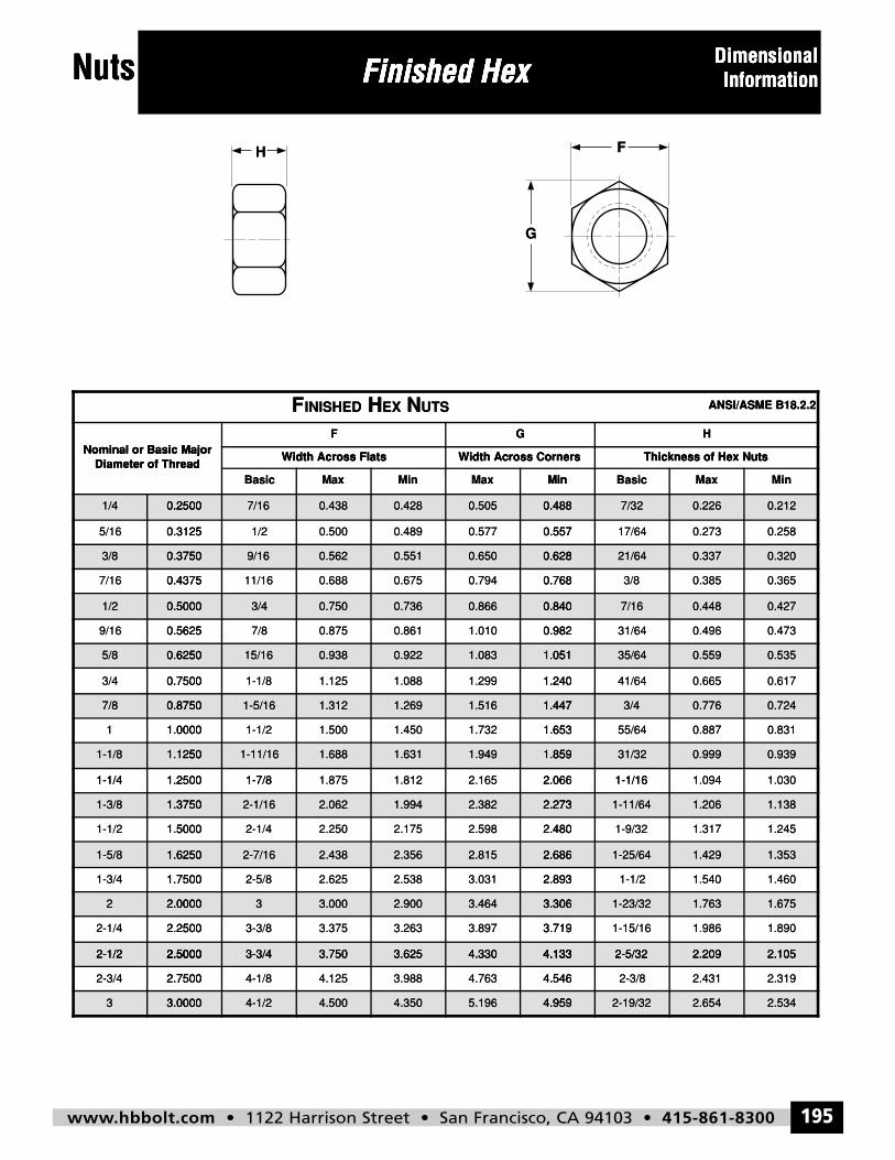
www.hbbolt.com • 1122 Harrison Street • San Francisco, CA 94103 • 415-861-8300 195
Nuts
H
G
F
Finished Hex DimensionalInformation
FINISHED HEX NUTS ANSI/ASME B18.2.2
Nominal or Basic MajorDiameter of Thread
F G H
Width Across Flats Width Across Corners Thickness of Hex Nuts
Basic Max Min Max Min Basic Max Min
1/4 0.2500 7/16 0.438 0.428 0.505 0.488 7/32 0.226 0.212
5/16 0.3125 1/2 0.500 0.489 0.577 0.557 17/64 0.273 0.258
3/8 0.3750 9/16 0.562 0.551 0.650 0.628 21/64 0.337 0.320
7/16 0.4375 11/16 0.688 0.675 0.794 0.768 3/8 0.385 0.365
1/2 0.5000 3/4 0.750 0.736 0.866 0.840 7/16 0.448 0.427
9/16 0.5625 7/8 0.875 0.861 1.010 0.982 31/64 0.496 0.473
5/8 0.6250 15/16 0.938 0.922 1.083 1.051 35/64 0.559 0.535
3/4 0.7500 1-1/8 1.125 1.088 1.299 1.240 41/64 0.665 0.617
7/8 0.8750 1-5/16 1.312 1.269 1.516 1.447 3/4 0.776 0.724
1 1.0000 1-1/2 1.500 1.450 1.732 1.653 55/64 0.887 0.831
1-1/8 1.1250 1-11/16 1.688 1.631 1.949 1.859 31/32 0.999 0.939
1-1/4 1.2500 1-7/8 1.875 1.812 2.165 2.066 1-1/16 1.094 1.030
1-3/8 1.3750 2-1/16 2.062 1.994 2.382 2.273 1-11/64 1.206 1.138
1-1/2 1.5000 2-1/4 2.250 2.175 2.598 2.480 1-9/32 1.317 1.245
1-5/8 1.6250 2-7/16 2.438 2.356 2.815 2.686 1-25/64 1.429 1.353
1-3/4 1.7500 2-5/8 2.625 2.538 3.031 2.893 1-1/2 1.540 1.460
2 2.0000 3 3.000 2.900 3.464 3.306 1-23/32 1.763 1.675
2-1/4 2.2500 3-3/8 3.375 3.263 3.897 3.719 1-15/16 1.986 1.890
2-1/2 2.5000 3-3/4 3.750 3.625 4.330 4.133 2-5/32 2.209 2.105
2-3/4 2.7500 4-1/8 4.125 3.988 4.763 4.546 2-3/8 2.431 2.319
3 3.0000 4-1/2 4.500 4.350 5.196 4.959 2-19/32 2.654 2.534
Nuts Finished HexFinished Hex DimensionalDimensionalNuts Finished Hex
H
Finished Hex
G
Information
F
Information
HINISHEDF UTSNEXH ANSI/ASME B18.2.2ANSI/ASME B18.2.2
Diameter of ThreadNominal or Basic Major
1/4 0.2500
0.31255/16
3/8 0.3750
0.43757/16
MaxBasic
Width Across Flats
F G
Diameter of ThreadNominal or Basic Major
0.2500 7/16 0.438
0.5001/20.3125
0.3750 9/16 0.562
0.68811/160.4375
MinMaxMin
Width Across CornersWidth Across Flats
G
0.428 0.505 0.488
0.5570.5770.489
0.551 0.650 0.628
0.7680.7940.675
MaxBasicMin
Thickness of Hex NutsWidth Across Corners
H
0.488 7/32 0.226
0.27317/640.557
0.628 21/64 0.337
0.3853/80.768
Min
Thickness of Hex Nuts
0.212
0.258
0.320
0.365
1/2 0.5000
0.56259/16
5/8 0.6250
0.75003/4
7/8 0.8750
1.00001
1-1/8 1.1250
1-1/4
0.5000 3/4 0.750
0.8757/80.5625
0.6250 15/16 0.938
1.1251-1/80.7500
0.8750 1-5/16 1.312
1.5001-1/21.0000
1.1250 1-11/16 1.688
1-7/8
0.736 0.866 0.840
0.9821.0100.861
0.922 1.083 1.051
1.2401.2991.088
1.269 1.516 1.447
1.6531.7321.450
1.631 1.949 1.859
0.840 7/16 0.448
0.49631/640.982
1.051 35/64 0.559
0.66541/641.240
1.447 3/4 0.776
0.88755/641.653
1.859 31/32 0.999
1-1/16
0.427
0.473
0.535
0.617
0.724
0.831
0.939
1.25001-1/4
1-3/8 1.3750
1.50001-1/2
1-5/8 1.6250
1.75001-3/4
2 2.0000
2.25002-1/4
2-1/2 2.5000
1.8751-7/81.2500
1.3750 2-1/16 2.062
2.2502-1/41.5000
1.6250 2-7/16 2.438
2.6252-5/81.7500
2.0000 3 3.000
3.3753-3/82.2500
2.5000 3-3/4 3.750
2.0662.1651.812
1.994 2.382 2.273
2.4802.5982.175
2.356 2.815 2.686
2.8933.0312.538
2.900 3.464 3.306
3.7193.8973.263
3.625 4.330 4.133
1.0941-1/162.066
2.273 1-11/64 1.206
1.3171-9/322.480
2.686 1-25/64 1.429
1.5401-1/22.893
3.306 1-23/32 1.763
1.9861-15/163.719
4.133 2-5/32 2.209
1.030
1.138
1.245
1.353
1.460
1.675
1.890
2.1052-1/2 2.5000
2.75002-3/4
3 3.0000
2.5000 3-3/4 3.750
4.1254-1/82.7500
3.0000 4-1/2 4.500
3.625 4.330 4.133
4.5464.7633.988
4.350 5.196 4.959
4.133 2-5/32 2.209
2.4312-3/84.546
4.959 2-19/32 2.654
2.105
2.319
2.534
hbbolt_pgs_193_224_17061_template_NEW_USE 2/8/16 11:16 AM Page 195
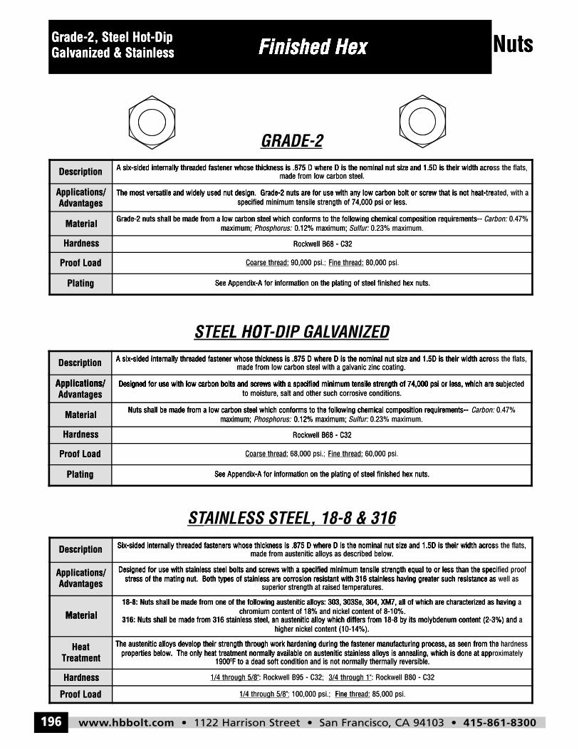
www.hbbolt.com • 1122 Harrison Street • San Francisco, CA 94103 • 415-861-8300196
NutsFinished HexGrade-2, Steel Hot-DipGalvanized & Stainless
Description A six-sided internally threaded fastener whose thickness is .875 D where D is the nominal nut size and 1.5D is their width across the flats,made from low carbon steel.
Applications/Advantages
The most versatile and widely used nut design. Grade-2 nuts are for use with any low carbon bolt or screw that is not heat-treated, with aspecified minimum tensile strength of 74,000 psi or less.
Material Grade-2 nuts shall be made from a low carbon steel which conforms to the following chemical composition requirements-- Carbon: 0.47%maximum; Phosphorus: 0.12% maximum; Sulfur: 0.23% maximum.
Hardness Rockwell B68 - C32
Proof Load Coarse thread: 90,000 psi.; Fine thread: 80,000 psi.
Plating See Appendix-A for information on the plating of steel finished hex nuts.
Description A six-sided internally threaded fastener whose thickness is .875 D where D is the nominal nut size and 1.5D is their width across the flats,made from low carbon steel with a galvanic zinc coating.
Applications/Advantages
Designed for use with low carbon bolts and screws with a specified minimum tensile strength of 74,000 psi or less, which are subjectedto moisture, salt and other such corrosive conditions.
Material Nuts shall be made from a low carbon steel which conforms to the following chemical composition requirements-- Carbon: 0.47%maximum; Phosphorus: 0.12% maximum; Sulfur: 0.23% maximum.
Hardness Rockwell B68 - C32
Proof Load Coarse thread: 68,000 psi.; Fine thread: 60,000 psi.
Plating See Appendix-A for information on the plating of steel finished hex nuts.
Description Six-sided internally threaded fasteners whose thickness is .875 D where D is the nominal nut size and 1.5D is their width across the flats,made from austenitic alloys as described below.
Applications/Advantages
Designed for use with stainless steel bolts and screws with a specified minimum tensile strength equal to or less than the specified proofstress of the mating nut. Both types of stainless are corrosion resistant with 316 stainless having greater such resistance as well as
superior strength at raised temperatures.
Material18-8: Nuts shall be made from one of the following austenitic alloys: 303, 303Se, 304, XM7, all of which are characterized as having a
chromium content of 18% and nickel content of 8-10%.316: Nuts shall be made from 316 stainless steel, an austenitic alloy which differs from 18-8 by its molybdenum content (2-3%) and a
higher nickel content (10-14%).
HeatTreatment
The austenitic alloys develop their strength through work hardening during the fastener manufacturing process, as seen from the hardnessproperties below. The only heat treatment normally available on austenitic stainless alloys is annealing, which is done at approximately
19000F to a dead soft condition and is not normally thermally reversible.
Hardness 1/4 through 5/8": Rockwell B95 - C32; 3/4 through 1": Rockwell B80 - C32
Proof Load 1/4 through 5/8": 100,000 psi.; Fine thread: 85,000 psi.
Grade-2, Steel Hot-DipGrade-2, Steel Hot-Dip Finished HexFinished Hex NutsGalvanized & StainlessGalvanized & Stainless Finished Hex
GRADE-2
Finished Hex Nuts
Description
AdvantagesApplications/
Material
Hardness
Proof Load
A six-sided internally threaded fastener whose thickness is .875 D where D is the nominal nut size and 1.5D is their width acro
The most versatile and widely used nut design. Grade-2 nuts are for use with any low carbon bolt or screw that is not heat-tre
maximum;Grade-2 nuts shall be made from a low carbon steel which conforms to the following chemical composition requirements--
made from low carbon steel.A six-sided internally threaded fastener whose thickness is .875 D where D is the nominal nut size and 1.5D is their width acro
specified minimum tensile strength of 74,000 psi or less.The most versatile and widely used nut design. Grade-2 nuts are for use with any low carbon bolt or screw that is not heat-tre
0.12% maximum;Phosphorus:maximum;Grade-2 nuts shall be made from a low carbon steel which conforms to the following chemical composition requirements--
Rockwell B68 - C32
90,000 psi.;thread:Coarse Fine
made from low carbon steel.A six-sided internally threaded fastener whose thickness is .875 D where D is the nominal nut size and 1.5D is their width acro
specified minimum tensile strength of 74,000 psi or less.The most versatile and widely used nut design. Grade-2 nuts are for use with any low carbon bolt or screw that is not heat-tre
0.23% maximum.Sulfur:: 0.12% maximum;Grade-2 nuts shall be made from a low carbon steel which conforms to the following chemical composition requirements--
Rockwell B68 - C32
thread: 80,000 psi.
ss the flats,A six-sided internally threaded fastener whose thickness is .875 D where D is the nominal nut size and 1.5D is their width acro
ated, with aThe most versatile and widely used nut design. Grade-2 nuts are for use with any low carbon bolt or screw that is not heat-tre
0.47%Carbon:Grade-2 nuts shall be made from a low carbon steel which conforms to the following chemical composition requirements--
Plating
Description
Applications/
STEEL HOT
See Appendix-A for information on the plating of steel finished hex nuts.
A six-sided internally threaded fastener whose thickness is .875 D where D is the nominal nut size and 1.5D is their width acro
Designed for use with low carbon bolts and screws with a specified minimum tensile strength of 74,000 psi or less, which are su
T-DIP GAL-DIP GALEL HOT VANIZEDAV
See Appendix-A for information on the plating of steel finished hex nuts.
made from low carbon steel with a galvanic zinc coating.A six-sided internally threaded fastener whose thickness is .875 D where D is the nominal nut size and 1.5D is their width acro
Designed for use with low carbon bolts and screws with a specified minimum tensile strength of 74,000 psi or less, which are su
ANIZED
See Appendix-A for information on the plating of steel finished hex nuts.
made from low carbon steel with a galvanic zinc coating.A six-sided internally threaded fastener whose thickness is .875 D where D is the nominal nut size and 1.5D is their width acro
Designed for use with low carbon bolts and screws with a specified minimum tensile strength of 74,000 psi or less, which are su
ss the flats,A six-sided internally threaded fastener whose thickness is .875 D where D is the nominal nut size and 1.5D is their width acro
bjectedDesigned for use with low carbon bolts and screws with a specified minimum tensile strength of 74,000 psi or less, which are suAdvantages
Applications/
Material
Hardness
Proof Load
Plating
Designed for use with low carbon bolts and screws with a specified minimum tensile strength of 74,000 psi or less, which are su
maximum;Nuts shall be made from a low carbon steel which conforms to the following chemical composition requirements--
See Appendix-A for information on the plating of steel finished hex nuts.
to moisture, salt and other such corrosive conditions.Designed for use with low carbon bolts and screws with a specified minimum tensile strength of 74,000 psi or less, which are su
0.12% maximum;Phosphorus:maximum;Nuts shall be made from a low carbon steel which conforms to the following chemical composition requirements--
Rockwell B68 - C32
68,000 psi.;thread:Coarse Fine
See Appendix-A for information on the plating of steel finished hex nuts.
to moisture, salt and other such corrosive conditions.Designed for use with low carbon bolts and screws with a specified minimum tensile strength of 74,000 psi or less, which are su
0.23% maximum.Sulfur:: 0.12% maximum;Nuts shall be made from a low carbon steel which conforms to the following chemical composition requirements--
Rockwell B68 - C32
thread: 60,000 psi.
See Appendix-A for information on the plating of steel finished hex nuts.
bjectedDesigned for use with low carbon bolts and screws with a specified minimum tensile strength of 74,000 psi or less, which are su
0.47%Carbon:Nuts shall be made from a low carbon steel which conforms to the following chemical composition requirements--
Description
AdvantagesApplications/
Material
TAINLESS STEEL, 18-8 & 316AIN STSix-sided internally threaded fasteners whose thickness is .875 D where D is the nominal nut size and 1.5D is their width acros
stress of the mating nut. Both types of stainless are corrosion resistant with 316 stainless having greater such resistance asDesigned for use with stainless steel bolts and screws with a specified minimum tensile strength equal to or less than the spec
Nuts shall be made from one of the following austenitic alloys: 303, 303Se, 304, XM7, all of which are characterized as having18-8:
, NLESS STEEL, 18-
made from austenitic alloys as described below.Six-sided internally threaded fasteners whose thickness is .875 D where D is the nominal nut size and 1.5D is their width acros
superior strength at raised temperatures.stress of the mating nut. Both types of stainless are corrosion resistant with 316 stainless having greater such resistance as
Designed for use with stainless steel bolts and screws with a specified minimum tensile strength equal to or less than the spec
chromium content of 18% and nickel content of 8-10%. Nuts shall be made from one of the following austenitic alloys: 303, 303Se, 304, XM7, all of which are characterized as having
-8 & 316
made from austenitic alloys as described below.Six-sided internally threaded fasteners whose thickness is .875 D where D is the nominal nut size and 1.5D is their width acros
superior strength at raised temperatures.stress of the mating nut. Both types of stainless are corrosion resistant with 316 stainless having greater such resistance as
Designed for use with stainless steel bolts and screws with a specified minimum tensile strength equal to or less than the spec
chromium content of 18% and nickel content of 8-10%. Nuts shall be made from one of the following austenitic alloys: 303, 303Se, 304, XM7, all of which are characterized as having
s the flats,Six-sided internally threaded fasteners whose thickness is .875 D where D is the nominal nut size and 1.5D is their width acros
well asstress of the mating nut. Both types of stainless are corrosion resistant with 316 stainless having greater such resistance asified proofDesigned for use with stainless steel bolts and screws with a specified minimum tensile strength equal to or less than the spec
a Nuts shall be made from one of the following austenitic alloys: 303, 303Se, 304, XM7, all of which are characterized as having
Material
TreatmentHeat
Hardness
Proof Load
Nuts shall be made from 316 stainless steel, an austenitic alloy which differs from 18-8 by its molybdenum content (2-3%) and 316:
1900properties below. The only heat treatment normally available on austenitic stainless alloys is annealing, which is done at app
The austenitic alloys develop their strength through work hardening during the fastener manufacturing process, as seen from the
th 1/4
higher nickel content (10-14%). Nuts shall be made from 316 stainless steel, an austenitic alloy which differs from 18-8 by its molybdenum content (2-3%) and
F to a dead soft condition and is not normally thermally reversible.01900properties below. The only heat treatment normally available on austenitic stainless alloys is annealing, which is done at app
The austenitic alloys develop their strength through work hardening during the fastener manufacturing process, as seen from the
g : Rockwell B95 - C32;5/8"hrough 3/4 through 1"
100,000 psi.; g 1/4 through 5/8": Fine
higher nickel content (10-14%). Nuts shall be made from 316 stainless steel, an austenitic alloy which differs from 18-8 by its molybdenum content (2-3%) and
F to a dead soft condition and is not normally thermally reversible.properties below. The only heat treatment normally available on austenitic stainless alloys is annealing, which is done at app
The austenitic alloys develop their strength through work hardening during the fastener manufacturing process, as seen from the
g : Rockwell B80 - C32 through 1"
thread: 85,000 psi.Fine
a Nuts shall be made from 316 stainless steel, an austenitic alloy which differs from 18-8 by its molybdenum content (2-3%) and
roximatelyproperties below. The only heat treatment normally available on austenitic stainless alloys is annealing, which is done at app hardnessThe austenitic alloys develop their strength through work hardening during the fastener manufacturing process, as seen from the
hbbolt_pgs_193_224_17061_template_NEW_USE 2/8/16 11:16 AM Page 196
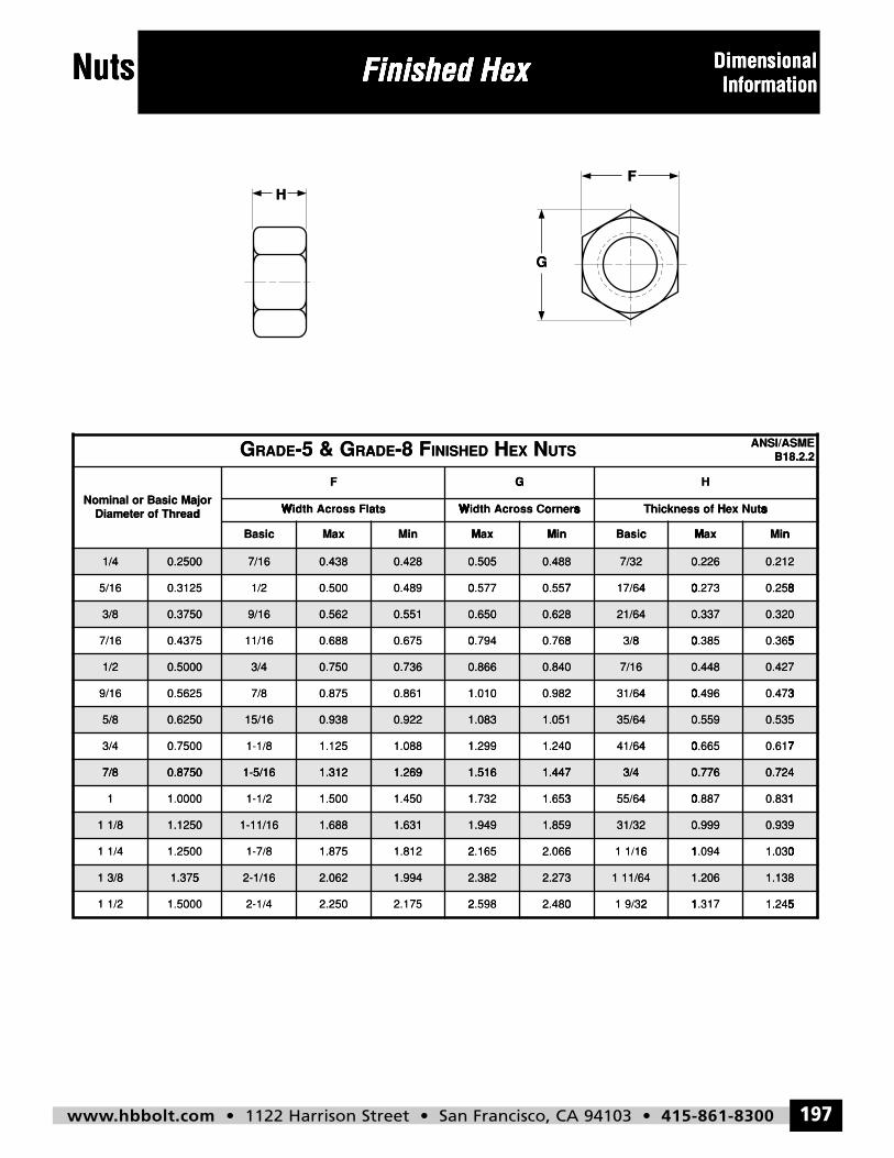
www.hbbolt.com • 1122 Harrison Street • San Francisco, CA 94103 • 415-861-8300 197
Nuts
H
G
F
Finished Hex DimensionalInformation
G EDAR 5- & G EDAR 8- F DEHSINI H XE N STUEMSA/ISNA2.2.81B
rojaMcisaBrolanimoNdaerhTforetemaiD
F G H
stalFssorcAhtdiW srenroCssorcAhtdiW stuNxeHfossenkcihT
cisaB xaM niM xaM niM cisaB xaM niM
4/1 0052.0 61/7 834.0 824.0 505.0 884.0 23/7 622.0 212.0
61/5 5213.0 2/1 005.0 984.0 775.0 755.0 46/71 372.0 852.0
8/3 0573.0 61/9 265.0 155.0 056.0 826.0 46/12 733.0 023.0
61/7 5734.0 61/11 886.0 576.0 497.0 867.0 8/3 583.0 563.0
2/1 0005.0 4/3 057.0 637.0 668.0 048.0 61/7 844.0 724.0
61/9 5265.0 8/7 578.0 168.0 010.1 289.0 46/13 694.0 374.0
8/5 0526.0 61/51 839.0 229.0 380.1 150.1 46/53 955.0 535.0
4/3 0057.0 8/1-1 521.1 880.1 992.1 042.1 46/14 566.0 716.0
8/7 0578.0 61/5-1 213.1 962.1 615.1 744.1 4/3 677.0 427.0
1 0000.1 2/1-1 005.1 054.1 237.1 356.1 46/55 788.0 138.0
8/11 0521.1 61/11-1 886.1 136.1 949.1 958.1 23/13 999.0 939.0
4/11 0052.1 8/7-1 578.1 218.1 561.2 660.2 61/11 490.1 030.1
8/31 573.1 61/1-2 260.2 499.1 283.2 372.2 46/111 602.1 831.1
2/11 0005.1 4/1-2 052.2 571.2 895.2 084.2 23/91 713.1 542.1
Nuts Finished HexFinished Hex DimensionalDimensionalNuts Finished Hex
H
Finished Hex Information
F
Information
G
Diameter of ThreadNominal or Basic Ma
1/4 0.250
5 0.312/16
B xMaasic
Width Across Fla
F G
dajor
RAG- &5RADEG
0 7/16 0.438
00.5021/5
M nM cxManMi
Width Across Coats
G
NEXHINISHED- F88ADE
0.428 0.505 0
0 70 470.5790.48
xMacBasinMi
Thickness of HsW soW srW snW seW sr
H
UTS
.488 7/32 0.226
30.27417/67.55
nM nMM ni
sW sHW seW sxW sNW suW st
B18.2.2ANSI/AA/ SME
0
80 800 8.0 820 85
.212
3/8 0.375
7 0.437//16
1/2 0.500
9 0.562//16
5/8 0.625
3 0.750//4
7/8 0 875
0 9/16 0.562
80.6861 /1/15
0 3/4 0.750
50.87/87/5
0 15/16 0.938
51.1281- /1/0
0 1-5/16 1 312
0.551 0.650 0
0 80 840.7950.67
0.736 0.866 0
1 20 401.0110.86
0.922 1.083 1
1 01 491.2981.08
1 269 1 516 1
.628 21/64 0.337
50.38/83/8.76
.840 7/16 0.448
60.4943 /1/62.98
.051 35/64 0.559
50.6644 /1/60.24
447 3/4 0 776
0
50 500 5.0 530 56
.320
0
30 300 3.0 340 37
.427
0
70 700 7.0 760 71
.535
0 7247/8 0.875
1 1.000
1 1/8 1.125
1 1.250/1/4
1 3/8 1.375
1 1.500/1/2
0 1 5/16 1.312
01.5021- /1/0
0 1-11/16 1.688
51.8781- /7/0
5 2-1/16 2.062
02.2542- /1/0
1.269 1.516 1
1 31 421.7301.45
1.631 1.949 1
2 62 652.1621.81
1.994 2.382 2
2 02 282.5952.17
.447 3/4 0.776
70.8845 /5/63.65
.859 31/32 0.999
41.0961 /1/16.06
.273 1 11/64 1.206
71.3121 /9/30.48
0
10 100 1.0 180 13
.724
0
01 011 0.1 001 03
.939
1
51 511 5.1 521 54
.138
114
hbbolt_pgs_193_224_17061_template_NEW_USE 2/8/16 11:16 AM Page 197
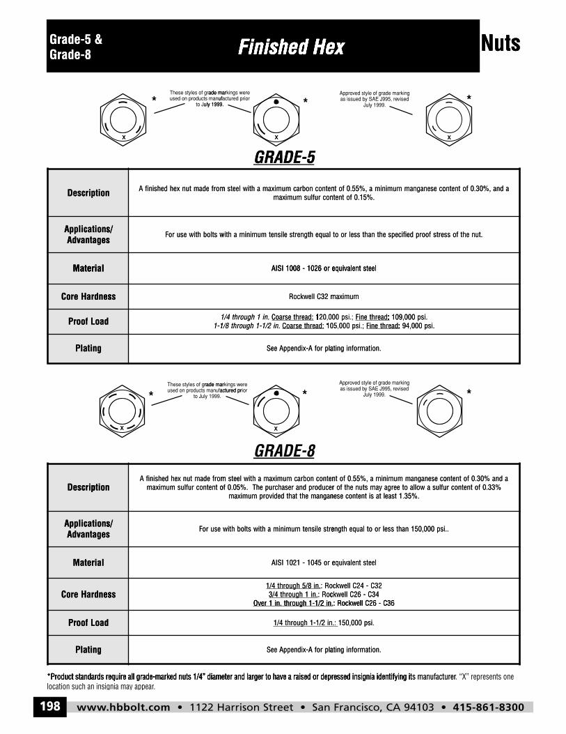
www.hbbolt.com • 1122 Harrison Street • San Francisco, CA 94103 • 415-861-8300198
Nuts
x x
x x
Finished HexGrade-5 &Grade-8
noitpircseD adna,%03.0fotnetnocesenagnammuminima,%55.0fotnetnocnobracmumixamahtiwleetsmorfedamtunxehdehsinifA.%51.0fotnetnocruflusmumixam
/snoitacilppAsegatnavdA
.tunehtfossertsfoorpdeificepsehtnahtsselrootlauqehtgnertselisnetmuminimahtiwstlobhtiwesuroF
lairetaM leetstnelaviuqero6201-8001ISIA
ssendraHeroC mumixam23CllewkcoR
daoLfoorP .ni1hguorht4/1 :daerhtesraoC ;.isp000,021 :daerhteniF .isp000,901.ni2/1-1hguorht8/1-1 :daerhtesraoC ;.isp000,501 :daerhteniF .isp000,49
gnitalP .noitamrofnignitalprofA-xidneppAeeS
noitpircseDadna%03.0fotnetnocesenagnammuminima,%55.0fotnetnocnobracmumixamahtiwleetsmorfedamtunxehdehsinifA
%33.0fotnetnocruflusawollaoteergayamstunehtforecudorpdnaresahcrupehT.%50.0fotnetnocruflusmumixam.%53.1tsaeltasitnetnocesenagnamehttahtdedivorpmumixam
/snoitacilppAsegatnavdA
..isp000,051nahtsselrootlauqehtgnertselisnetmuminimahtiwstlobhtiwesuroF
lairetaM leetstnelaviuqero5401-1201ISIA
ssendraHeroC.ni8/5hguorht4/1 23C-42CllewkcoR:
.ni1hguorht4/3 43C-62CllewkcoR:.ni2/1-1hguorht.ni1revO 63C-62CllewkcoR:
daoLfoorP :.ni2/1-1hguorht4/1 .isp000,051
gnitalP .noitamrofnignitalprofA-xidneppAeeS
x
Grade-5 & Finished HexFinished Hex NutsGrade-8
x
uly 1999.to Jufused on products man
ade marThese styles of gr
*
Finished Hex
x
GRADE-5
uly 1999.ioractured pruf
kings wereade mar
*
Finished Hex
uly 1999.Jvisedy SAE J995, reas issued b
rade markinged style of gvAppro
Nuts
*
x
Description
AdvantagesApplications
Material
A finished hex nut made from
sFor use with bolts w
/
GRADE-5
maximum sulfur conm steel with a maximum carbon conten
with a minimum tensile strength equal
AISI 1008 1026 or e
ntent of 0.15%.nt of 0.55%, a minimum manganese co
to or less than the specified proof stre
equivalent steel
ontent of 0.30%, and a
ss of the nut.
Material
Core Hardnes
Proof Load
Plating
ss
1-1
AISI 1008 - 1026 or e
Rockwell C32 m
Coarse thread:1/44/ thht rough 1 inni . 1 ,20,00Coarse thread:1/88/ thht rough 1-1/22/ inni . 10
See Appendix-A for pla
equivalent steel
maximum
:1 :F1 :i1 :n1 :e1 :t1 :h1 :r1 :e1 :a1 :d;p00 psi.; 109,000 psi.:1 :F1 :i1 :n1 :e1 :t1 :h1 :r1 :e1 :a1 :d;p,05,000 psi.; 94,000 psi.
ating information.
Description
x
* uly 1999.to Jactured prufused on products man
rade marThese styles of g
maximum sulfur content oA finished hex nut made from
x
*
GRADE-8
ioractured prerekings wrade mar
of 0.05%. The purchaser and producerm steel with a maximum carbon conten
uly 1999.Jvisedy SAE J995, reas issued b
kingade marred style of gvAppro
r of the nuts may agree to allow a sulfunt of 0.55%, a minimum manganese co
*
ur content of 0.33%ontent of 0.30% and a
p
AdvantagesApplications
Material
Core Hardnes
sFor use
/
ss
maximum provided that the mangan
with bolts with a minimum tensile stre
AISI 1021 - 1045 or e
1/4 through 5/8 in.3/4 through 1 in.
: Ro
Over 1 in through 1 1/2 in: Roc
nese content is at least 1.35%.
ength equal to or less than 150,000 ps
equivalent steel
ckwell C24 - C32ckwell C26 - C34: Rockwell C26 C36
i..
g *Product standards require all grade-marked nuts 1/4” diameter and larger to have a raised or depressed insignia identifying it
Proof Load
Plating
location such an insig . g y pp*Product standards require all grade-marked nuts 1/4” diameter and larger to have a raised or depressed insignia identifying it
gnia may appear*Product standards require all grade-marked nuts 1/4” diameter and larger to have a raised or depressed insignia identifying it
Over 1 in. through 1-1/2 in.
1/4 through 1-1/2 in
See Appendix-A for pla
s manufacturer*Product standards require all grade-marked nuts 1/4” diameter and larger to have a raised or depressed insignia identifying it
: Rockwell C26 - C36
.: 150,000 psi.
ating information.
115
. “X” represents ones manufacturer
hbbolt_pgs_193_224_17061_template_NEW_USE 2/8/16 11:16 AM Page 198
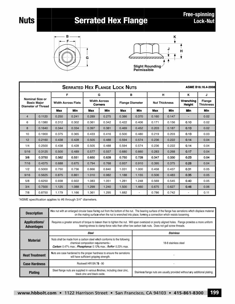
www.hbbolt.com • 1122 Harrison Street • San Francisco, CA 94103 • 415-861-8300 199
Serrated Hex FlangeFree-spinning
Lock-NutNuts
Serrated Hex Flange
Serrated Hex Flange
ree-spinningF
ree-spinning
Nuts
Serrated Hex Flange
Serrated Hex Flange
Serrated Hex Flange
Lock-Nut
Diameter of ThreadBasic Major
Nominal Size or
FXE HDETARRES
MaxMinMax
Cornersidth WAcross Flatsidth W
F
STUNKCOLEGNAL F
MinMaxMin
Flange DiameterCornersAcross
BG
MinMinMax
Heightrenching WNut Thickness
KH
ASME B18.16.4-2008
MinMin
ThicknessFlange
Heightrenching
J
ASME B18.16.4-2008
0.3125
0.37503/8
5/16
0.2160
0.25001/4
12
0.1640
0.190010
8
120
0.13806
0.14
0.577
0.6500.5510.562
0.4890.500
0.505
0.5050.4280.438
0.4280.438
0.397
0.4330.3650.375
0.3340.344
0.289
0.3610.3020.312
0.2410.250
MaxMinMax
0.660
0.7280.7500.628
0.6800.557
0.574
0.5740.5940.488
0.5940.488
0.452
0.4800.5000.416
0.4690.381
0.370
0.4060.4220.342
0.3860.275
MinMaxMin
0.17
0.230.3300.347
0.2680.283
0.14
0.140.2220.236
0.2220.236
0.13
0.130.2030.219
0.1870.203
-
0.100.1560.171
0.1470.160
MinMinMax
0.04
0.040.23
0.17
0.04
0.040.14
0.14
0.02
0.030.13
0.13
0.02
0.020.10
MinMin
0.43757/16
0.7500
0.37503/8
0.87507/83/4
0.5625
0.62505/8
9/16
0.50001/2
0.7940.6750.688
1.299
0.6500.5510.562
1.3611.1661.1791.0881.125
1.010
1.0830.9220.938
0.8610.875
0.8660.7360.750
0.9100.9370.768
1.460
0.7280.7500.628
-1.6821.2951.5001.240
1.155
1.2481.2811.051
1.1880.982
1.0001.0310.840
0.395
0.46
0.230.3300.347
-0.7420.7860.6270.675
0.35
0.400.5450.569
0.4830.506
0.26
0.310.4370.458
0.375
0.06
0.040.23
10.10.46
0.05
0.050.40
0.35
0.04
0.050.31
0.26
Description
Material
Advantagespplications/ A
PhosphorusCarbon
Steel
rSulfur
Stainless
140
Plating
Case Hardness
reatmentTHeat
-
-
hbbolt_pgs_193_224_17061_template_NEW_USE 2/8/16 11:16 AM Page 199
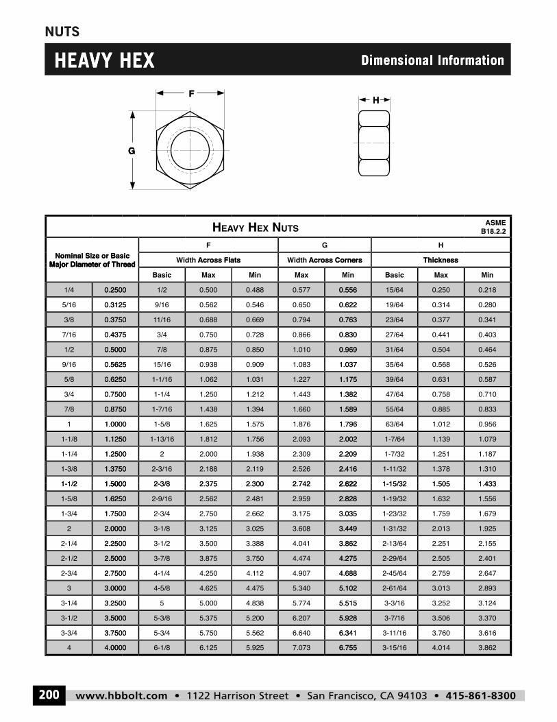
www.hbbolt.com • 1122 Harrison Street • San Francisco, CA 94103 • 415-861-8300200
NUTS
H
G
F
HEAVY HEX Dimensional Information
NUTS
VY HEXHEAVY HEX
G
F
Dimensional Information
H
Dimensional Information
Major Diameter of ThreadNominal Size or Basic
AEH
Across Flatsidth W
F
Major Diameter of ThreadNominal Size or Basic
G
STU NXE HYVAV
Across Cornersidth WAcross Flats
G
ThicknessAcross Corners
H
Thickness
B18.2.2ASME
0.5000
0.56259/16
1/2
0.3750
0.43757/16
3/8
0.2500
0.31255/16
1/4
Major Diameter of Thread
0.875
0.93815/160.5625
7/80.5000
0.688
0.7503/40.4375
1/1610.3750
0.500
0.5629/160.3125
1/20.2500
MaxBasicMajor Diameter of Thread
0.969
1.0371.0830.909
1.0100.850
0.763
0.8300.8660.728
0.7940.669
0.556
0.6220.6500.546
0.5770.488
MaxMin
0.504
0.56835/641.037
31/640.969
0.377
0.44127/640.830
23/640.763
0.250
0.31419/640.622
15/640.556
MaxBasicMin
0.464
0.526
0.341
0.403
0.218
0.280
Min
1.1250
1.25001-1/4
1-1/8
0.8750
1.00001
7/8
0.6250
0.75003/4
5/8
1.3750
1.50001-1/2
1-3/8
1.812
2.00021.2500
1-13/161.1250
1.438
1.6251-5/81.0000
1-7/160.8750
1.062
1.2501-1/40.7500
1-1/160.6250
2.188
2.3752-3/81.5000
2-3/161.3750
2.002
2.3091.938
2.0931.756
1.589
1.7961.8761.575
1.6601.394
1.175
1.3821.4431.212
1.2271.031
2.416
2.6222.7422.300
2.526192.1
2.209
1.1391-7/642.002
0.885
1.01263/641.796
55/641.589
0.631
0.75847/641.382
39/641.175
1.378
1.5051-15/322.622
1/321-12.416
1.2511-7/322.209
1.079
0.833
0.956
0.587
0.710
1.310
1.433
1.187
3.00003
2.5000
2.75002-3/4
2-1/2
2.0000
2.25002-1/4
2
1.6250
1.75001-3/4
1-5/8
1.50001-1/2
4.6254-5/83.0000
3.875
4.2504-1/42.7500
3-7/82.5000
3.125
3.5003-1/22.2500
3-1/82.0000
2.562
2.7502-3/41.7500
2-9/161.6250
2.3752-3/81.5000
5.1025.3404.475
4.275
4.6884.907124.1
4.4743.750
3.449
3.8624.0413.388
3.6083.025
2.828
3.0353.1752.662
2.9592.481
2.6222.7422.300
3.0132-61/645.102
2.505
2.7592-45/644.688
2-29/644.275
2.013
2.2512-13/643.862
1-31/323.449
1.632
1.7591-23/323.035
1-19/322.828
1.5051-15/322.622
2.893
2.401
2.647
1.925
2.155
1.556
1.679
1.433
160
4.00004
3.5000
3.75003-3/4
3-1/2
3.25003-1/4
6.1256-1/84.0000
5.375
5.7505-3/43.7500
5-3/83.5000
5.00053.2500
6.7557.0735.925
5.928
6.3416.6405.562
6.2075.200
5.5155.7744.838
4.0143-15/166.755
3.506
3.7601/163-16.341
3-7/165.928
3.2523-3/165.515
3.862
3.370
3.616
3.124
hbbolt_pgs_193_224_17061_template_NEW_USE 2/8/16 11:16 AM Page 200
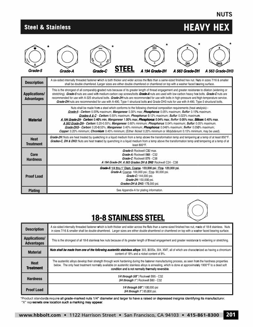
www.hbbolt.com • 1122 Harrison Street • San Francisco, CA 94103 • 415-861-8300 201
NUTS
x DH
x
DH3
x
x
HEAVY HEXSteel & Stainless
UTSN
Steel & Stainless
x
*
Grade-5
Steel & Stainless
Grade-CGrade-A
*
x
*
A 194 Grade-2HGrade-C STEEL
EA
x
DH
A 563 Grade-DHA 194 Grade-2H
*
H
VY HEX
* *
A 563 Grade-DH3A 563 Grade-DH
x
DH3
EA
Description
Material
Advantagespplications/ A
Grade-5
Grade-DH
Grade-5
CarbonA 194 Grade-2H---Grades-A & C
Carbon:--- Grade-55-
Grade-CGrade-A
Grade-2HGrade-A
PhosphorusManganeseePhosphorus Carbon:
PhosphorusManganesee
A 194 Grade-2HGrade-C STEEL
rr
r
Grade-A
SiliconSulfurPhosphorusSulfur
SulfurPhosphorus
A 563 Grade-DHA 194 Grade-2H
Grade-C
Silicon
A 563 Grade-DH3A 563 Grade-DH
Material
HardnessCore
reatmentTTreatmentHeat
r
Grades-C, DH & DH3:Grade-2H:
ChromiumCopperCarbon-- Grade-DH33-
Carbon-- A 563 Grade-DH H- Carbon-- A 194 Grade-2H H-
H
m
A 563 Grades DH & DH3A 194 Grade-2HGrade-CGrade-A:Grade-5:
miumPhosphorusManganese
ManganesePhosphorusManganesee
Grade-5:
3
rr
DH3
SulfurPhosphorusSulfurPhosphorus
SiliconSulfurrPhosphorus
Silicon
Proof Load
Plating
18-8 ST
Grade-5:
Grades-DH & DH3:Grade-2H:Grade-C:
CoarseGrade-A:
AINLESS S8-8 ST TAINLESS STEEL
AINLESS STEEL
Description
reatmentTHeat
Material
Advantagespplications/ A
Nuts shall be made from one of the following austenitic stainless alloys
18-8 ST
Nuts shall be made from one of the following austenitic stainless alloys
AINLESS S8 8 ST TAINLESS STEEL
AINLESS STEEL
Proof Load
Hardness
reatmentT
esnets one location such a marking may appearepr “X” rds roduct standar*Pr
esnets one location such a marking may appeare all grade-marked nuts 1/4” diameter and larequirds r
3/4 through 1”:1/4 through 5/8”:
3/4 through 1”:1/4 through 5/8”:
. esnets one location such a marking may appearger to have a raised or depre all grade-marked nuts 1/4” diameter and lar
essed insignia identifying its manufacturger to have a raised or depr
161
. eressed insignia identifying its manufactur
hbbolt_pgs_193_224_17061_template_NEW_USE 2/8/16 11:16 AM Page 201
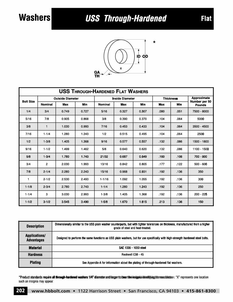
www.hbbolt.com • 1122 Harrison Street • San Francisco, CA 94103 • 415-861-8300202
Washers
ID OD
GATH
x
USS Through-Hardened Flat
Description Dimensionally similar to the USS plain washer counterparts, but with tighter tolerances on thickness, manufactured from a highergrade of steel and heat-treated.
Applications/Advantages Designed to perform the same functions as USS plain washers, but for use specifically with high-strength hardened steel bolts.
Material SAE 1035 - 1050 steel
Hardness Rockwell C38 - 45
Plating See Appendix-A for information about the plating of through-hardened flat washers.
SSU T HGUORH H- DENEDRA F TAL W SREHSA
eziStloBretemaiDedistuO retemaiDedisnI ssenkcihT etamixorppA
05reprebmuNsdnuoPlanimoN xaM niM lanimoN xaM niM xaM niM
4/1 4/3 947.0 727.0 61/5 723.0 703.0 080. 150. 0008-0057
61/5 8/7 509.0 868.0 8/3 093.0 073.0 401. 460. 0005
8/3 1 030.1 399.0 61/7 354.0 334.0 401. 460. 0054-0053
61/7 4/1-1 082.1 342.1 2/1 515.0 594.0 401. 460. 0052
2/1 8/3-1 504.1 863.1 61/9 775.0 755.0 231. 680. 0081-0051
61/9 2/1-1 994.1 264.1 8/5 046.0 026.0 231. 680. 0051-0011
8/5 4/3-1 087.1 347.1 23/12 786.0 946.0 061. 801. 008-007
4/3 2 030.2 399.1 61/31 248.0 508.0 771. 221. 006-005
8/7 4/1-2 082.2 342.2 61/51 869.0 139.0 291. 631. 053
1 2/1-2 035.2 394.2 61/1-1 290.1 550.1 291. 631. 003
8/1-1 4/3-2 087.2 347.2 4/1-1 082.1 342.1 291. 631. 052
4/1-1 3 030.3 399.2 8/3-1 504.1 863.1 291. 631. 522-002
2/1-1 2/1-3 545.3 094.3 8/5-1 076.1 516.1 312. 631. 051
ashersW USS Through-HardenedUSS Through-HardenedUSS Through-Hardened FlatashersW USS Through-HardenedUSS Through-Hardened
ID OD
USS Through-Hardened
OD
*
Flat
NominaBolt Size
THGA
nMixMaal
Outside Diameter
A-HHROUGHU TSSSS
x
THGA
M nM xxMalNomina
rInside Diamete
ASHEWLATFARDENED
nM nMM nixMani
sI sTI shI siI scI skI snI seI ss
RS
PoundsNumber per 50Approximate
1/4 3/4
5 /87///16
3/8 1
7 41- /1///16
1/2 1-3/8
9 21- /1///16
5/8 1 3/4
0.749 0.727
80.8650.90
1.030 0.993
31.2401.28
1.405 1.368
21.4691.49
1 780 1 743
5/16 0.327 0.3
0.300.39/83/
7/16 0.453 0.4
0.450.51/21/
9/16 0.577 0.5
0.600.64/85/
21/32 0 687 0 6
307 .080 .051
4.064.10037
433 .104 .064
4.064.10549
557 .132 .086
6.082.13062
649 160 108
7
0. 05. 00. 00
500 - 8000
3
0. 02. 05. 00
500 - 4500
1
0. 01. 01. 00. 00. 0-. 01. 05. 00
500 - 1800
700 8005/8 1-3/4
3 2//4
7/8 2-1/4
1 22- /1/
1-1/8 2-3/4
1 3/-1/4
1-1/2 3-1/2
1.780 1.743
2 31.99.030
2.280 2.243
32.4902.53
2.780 2.743
3 32.99.030
3 545 3 490
21/32 0.687 0.6
0.820.8461 /3/1
15/16 0.968 0.9
1.021.0961- /1/1
1-1/4 1.280 1.2
1.351.4081- /3/
1-5/8 1 670 1 6
649 .160 .108
2.127.17580
931 .192 .136
6.132.19505
243 .192 .136
6.132.19836
615 213 136
7
0. 05. 00. 00. 0-. 06. 00
00 - 800
3
0. 03. 00
50
2
5. 52. 50. 50. 5-. 52. 52
50
150
Description
AdvantagesApplications/
Material
1-1/2 3-1/2
Dimensionally similar to the USS plain washer counterparts, but with tighter tolerances on thickness, manufactured from a highe
Designed to perform the same functions as USS plain washers, but for use specifically with high-strength hardened steel bolts.
3.545 3.490
grade of steel and heat-treated.Dimensionally similar to the USS plain washer counterparts, but with tighter tolerances on thickness, manufactured from a highe
Designed to perform the same functions as USS plain washers, but for use specifically with high-strength hardened steel bolts.
SAE 1035 - 1050 steel
1-5/8 1.670 1.6
grade of steel and heat-treated.Dimensionally similar to the USS plain washer counterparts, but with tighter tolerances on thickness, manufactured from a highe
Designed to perform the same functions as USS plain washers, but for use specifically with high-strength hardened steel bolts.
SAE 1035 - 1050 steel
615 .213 .136
rDimensionally similar to the USS plain washer counterparts, but with tighter tolerances on thickness, manufactured from a highe
Designed to perform the same functions as USS plain washers, but for use specifically with high-strength hardened steel bolts.
150
168
such an insignia may appear*Product standards require all through-hardened washers 1/4” diameter and larger to bear the insignia identifying its manufactu
Material
Hardness
Plating
.such an insignia may appear*Product standards require all through-hardened washers 1/4” diameter and larger to bear the insignia identifying its manufactu
See Appendix-A for information about the plating of through-hardened flat washers.
*Product standards require all through-hardened washers 1/4” diameter and larger to bear the insignia identifying its manufactu
SAE 1035 - 1050 steel
Rockwell C38 - 45
See Appendix-A for information about the plating of through-hardened flat washers.
. “X” represents one locationrer*Product standards require all through-hardened washers 1/4” diameter and larger to bear the insignia identifying its manufactu
SAE 1035 - 1050 steel
Rockwell C38 - 45
See Appendix-A for information about the plating of through-hardened flat washers.
. “X” represents one location
hbbolt_pgs_193_224_17061_template_NEW_USE 2/8/16 11:16 AM Page 202
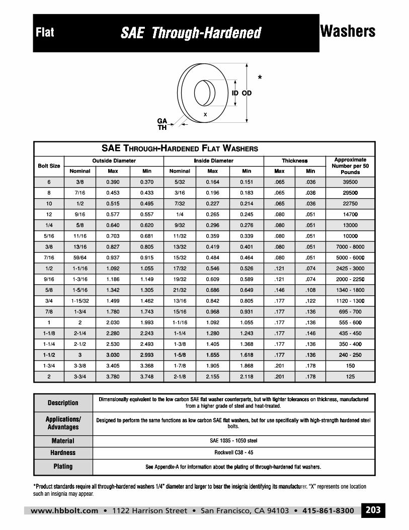
www.hbbolt.com • 1122 Harrison Street • San Francisco, CA 94103 • 415-861-8300 203
Washers
ID OD
GATH
x
SAE Through-HardenedFlat
Description Dimensionally equivalent to the low carbon SAE flat washer counterparts, but with tighter tolerances on thickness, manufacturedfrom a higher grade of steel and heat-treated.
Applications/Advantages
Designed to perform the same functions as low carbon SAE flat washers, but for use specifically with high-strength hardened steelbolts.
Material SAE 1035 - 1050 steel
Hardness Rockwell C38 - 45
Plating See Appendix-A for information about the plating of through-hardened flat washers.
EAS T HGUORH H- DENEDRA F TAL W SREHSA
eziStloBretemaiDedistuO retemaiDedisnI ssenkcihT etamixorppA
05reprebmuNsdnuoPlanimoN xaM niM lanimoN xaM niM xaM niM
6 8/3 093.0 073.0 23/5 461.0 151.0 560. 630. 00593
8 61/7 354.0 334.0 61/3 691.0 381.0 560. 630. 00592
01 2/1 515.0 594.0 23/7 722.0 412.0 560. 630. 05722
21 61/9 775.0 755.0 4/1 562.0 542.0 080. 150. 00741
4/1 8/5 046.0 026.0 23/9 692.0 672.0 080. 150. 00031
61/5 61/11 307.0 186.0 23/11 953.0 933.0 080. 150. 00001
8/3 61/31 728.0 508.0 23/31 914.0 104.0 080. 150. 0008-0007
61/7 46/95 739.0 519.0 23/51 484.0 464.0 080. 150. 0006-0005
2/1 61/1-1 290.1 550.1 23/71 645.0 625.0 121. 470. 0003-5242
61/9 61/3-1 681.1 941.1 23/91 906.0 985.0 121. 470. 0522-0002
8/5 61/5-1 243.1 503.1 23/12 686.0 946.0 641. 801. 0081-0431
4/3 23/51-1 994.1 264.1 61/31 248.0 508.0 771. 221. 0031-0211
8/7 4/3-1 087.1 347.1 61/51 869.0 139.0 771. 631. 007-596
1 2 030.2 399.1 61/1-1 290.1 550.1 771. 631. 006-555
8/1-1 4/1-2 082.2 342.2 4/1-1 082.1 342.1 771. 641. 054-534
4/1-1 2/1-2 035.2 394.2 8/3-1 504.1 863.1 771. 631. 004-053
2/1-1 3 030.3 399.2 8/5-1 556.1 816.1 771. 631. 052-042
4/3-1 8/3-3 504.3 863.3 8/7-1 509.1 868.1 102. 871. 051
2 4/3-3 087.3 847.3 8/1-2 551.2 811.2 102. 871. 521
Flat SAE Through-HardenedSAE Through-HardenedSAE Through-Hardened ashersWFlat SAE Through-HardenedSAE Through-Hardened
ID
SAE Through-Hardened
OD
*
ashersW
NomBolt Size
6 3
8 /7/
THGA
nMixMaminal
Outside Diameter
-HROUGHS TAE
3/8 0.390 0.370
30 4330 45/ 6/1
x
THGA
xMalNomina
rInside Diamete
ASWLATFARDENED-H
5/32 0.164
60 19/ 63/1
nM nMM nixManMi
sI sTI shI siI scI skI snI seI ss
SHERS
0.151 .065 .036
6. 60. 6350630 18
PoundsNumber per 50Approximate
3
0. 02. 09. 05. 00
9500
8 7/
10 1
1 /9/2
1/4 5
5 11/16
3/8 13
7 59//16
1/2 1-1
30.4330.456/1
/2 0.515 0.495
70.5570.57/ 6/1
5/8 0.640 0.620
10.6830.706/1
3/16 0.827 0.805
50.9170.934/9/6
1/16 1.092 1.055
60.1963/1
7/32 0.227
50.26/41/
9/32 0.296
90.35211/3
13/32 0.419
40.4821 /5/3
17/32 0.546
6.035.0630.18
0.214 .065 .036
1.050.0850.24
0.276 .080 .051
1.050.0890.33
0.401 .080 .051
1.050.0840.46
0.526 .121 .074
0. 02. 09. 05. 00
2
0. 01. 04. 07. 00
2750
1
0. 01. 00. 00. 00
3000
7
0. 05. 00. 00. 00. 0-. 06. 00. 00
000 - 8000
2425 - 3000
9 1-3//16
5/8 1-5
3 1-1//4
7/8 1-
1
1-1/8 2-
1 2-/-1/4
1 1/2
91.1461.186/3/1
5/16 1.342 1.305
21.4691.492/5/3
3/4 1.780 1.743
2 31.99.0301 2
1/4 2.280 2.243
32.4902.532/1/
3 3 030 2 993
90.6021 /9/3
21/32 0.686
20.8461 /3/1
15/16 0.968
21.0961- /1/1
1-1/4 1.280
51.4081- /3/
1 5/8 1 655
4.071.1290.58
0.649 .146 .108
2.127.1750.80
0.931 .177 .136
6.137.1751.05
1.243 .177 .146
6.137.1781.36
1 618 177 136
0. 02. 00. 00. 00. 0-. 02. 02. 05
1
0. 01. 01. 02. 00. 0-. 01. 03. 00
340 - 1800
6
0. 05. 05. 05. 0-. 06. 00
95 - 700
4
0. 03. 05. 00. 0-. 04. 00
35 - 450
240 250
Description
AdvantagesApplications/
1-1/2
1 3-/-3/4
2 3-
Dimensionally equivalent to the low carbon SAE flat washer counterparts, but with tighter tolerances on thickness, manufactured
Applications/ Designed to perform the same functions as low carbon SAE flat washers, but for use specifically with high-strength hardened ste
3 3.030 2.993
83.3653.408/3/
3/4 3.780 3.748
from a higher grade of steel and heat-treated.Dimensionally equivalent to the low carbon SAE flat washer counterparts, but with tighter tolerances on thickness, manufactured
bolts.Designed to perform the same functions as low carbon SAE flat washers, but for use specifically with high-strength hardened ste
1-5/8 1.655
51.9081- /7/
2-1/8 2.155
from a higher grade of steel and heat-treated.Dimensionally equivalent to the low carbon SAE flat washer counterparts, but with tighter tolerances on thickness, manufactured
Designed to perform the same functions as low carbon SAE flat washers, but for use specifically with high-strength hardened ste
1.618 .177 .136
8.171.2081.86
2.118 .201 .178
Dimensionally equivalent to the low carbon SAE flat washer counterparts, but with tighter tolerances on thickness, manufactured
elDesigned to perform the same functions as low carbon SAE flat washers, but for use specifically with high-strength hardened ste
2
0. 01. 05
40 - 250
125
such an insignia may appear*Product standards require all through-hardened washers 1/4” diameter and larger to bear the insignia identifying its manufactu
Material
Hardness
Plating
.such an insignia may appear*Product standards require all through-hardened washers 1/4” diameter and larger to bear the insignia identifying its manufactu
See Appendix-A for information about the plating of through-hardened flat washers.
*Product standards require all through-hardened washers 1/4” diameter and larger to bear the insignia identifying its manufactu
SAE 1035 - 1050 steel
Rockwell C38 - 45
See Appendix-A for information about the plating of through-hardened flat washers.
. “X” represents one locationrer*Product standards require all through-hardened washers 1/4” diameter and larger to bear the insignia identifying its manufactu
SAE 1035 - 1050 steel
Rockwell C38 - 45
See Appendix-A for information about the plating of through-hardened flat washers.
169
. “X” represents one location
See Appendix-A for information about the plating of through-hardened flat washers.
hbbolt_pgs_193_224_17061_template_NEW_USE 2/8/16 11:16 AM Page 203
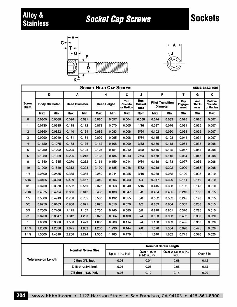
www.hbbolt.com • 1122 Harrison Street • San Francisco, CA 94103 • 415-861-8300204
SocketsAlloy &Stainless Socket Cap Screws
J
A
HC
G
D
K
T
F
SOCKET HEAD CAP SCREWS ASME B18.3-1998
ScrewDiam.
D A H C J F T G K
Body Diameter Head Diameter Head HeightTop
Chamferor Radius
HexSocket
Size
Fillet TransitionDiameter
KeyEngage-
ment
WallThick-ness
BottomChamfer
or Radius
Max Min Max Min Max Min Max Nom Max Min Min Min Max
0 0.0600 0.0568 0.096 0.091 0.060 0.057 0.004 0.050 0.074 0.063 0.025 0.020 0.007
1 0.0730 0.0695 0.118 0.112 0.073 0.070 0.005 1/16 0.087 0.076 0.031 0.025 0.007
2 0.0860 0.0822 0.140 0.134 0.086 0.083 0.008 5/64 0.102 0.090 0.038 0.029 0.007
3 0.0990 0.0949 0.161 0.154 0.099 0.095 0.008 5/64 0.115 0.103 0.044 0.034 0.007
4 0.1120 0.1075 0.183 0.176 0.112 0.108 0.009 3/32 0.130 0.118 0.051 0.038 0.008
5 0.1250 0.1202 0.205 0.198 0.125 0.121 0.012 3/32 0.145 0.132 0.057 0.043 0.008
6 0.1380 0.1329 0.226 0.218 0.138 0.134 0.013 7/64 0.158 0.145 0.064 0.047 0.008
8 0.1640 0.1585 0.270 0.262 0.164 0.159 0.014 9/64 0.188 0.173 0.077 0.056 0.008
10 0.1900 0.1840 0.312 0.303 0.190 0.185 0.018 5/32 0.218 0.202 0.090 0.065 0.008
1/4 0.2500 0.2435 0.375 0.365 0.250 0.244 0.025 3/16 0.278 0.262 0.120 0.095 0.010
5/16 0.3125 0.3053 0.469 0.457 0.312 0.306 0.033 1/4 0.347 0.329 0.151 0.119 0.010
3/8 0.3750 0.3678 0.562 0.550 0.375 0.368 0.040 5/16 0.415 0.398 0.182 0.143 0.010
7/16 0.4375 0.4294 0.656 0.642 0.438 0.430 0.047 3/8 0.484 0.465 0.213 0.166 0.015
1/2 0.5000 0.4919 0.750 0.735 0.500 0.492 0.055 3/8 0.552 0.532 0.245 0.190 0.015
5/8 0.6250 0.6163 0.938 0.921 0.625 0.616 0.070 1/2 0.689 0.664 0.307 0.238 0.015
3/4 0.7500 0.7406 1.125 1.107 0.750 0.740 0.085 5/8 0.828 0.801 0.370 0.285 0.015
7/8 0.8750 0.8647 1.312 1.293 0.875 0.864 0.100 3/4 0.963 0.933 0.432 0.333 0.020
1 1.0000 0.9886 1.500 1.479 1.000 0.988 0.114 3/4 1.100 1.069 0.495 0.380 0.020
1 1/4 1.2500 1.2336 1.875 1.852 1.250 1.236 0.144 7/8 1.370 1.334 0.620 0.475 0.020
1 1/2 1.5000 1.4818 2.250 2.224 1.500 1.485 0.176 1 1.640 1.602 0.745 0.570 0.020
Tolerance on Length
Nominal Screw SizeNominal Screw Length
Up to 1 in., Incl.Over 1 in. to2-1/2 in., Incl.
Over 2-1/2 to 6 in.,Incl. Over 6 in.
0 thru 3/8, Incl. -0.03 -0.04 -0.06 -0.12
7/16 thru 3/4, Incl. -0.03 -0.06 -0.08 -0.12
7/8 thru 1-1/2, Incl. -0.05 -0.10 -0.14 -0.20
Alloy & Socket Cap ScrewsSocket Cap ScrewsSocket Cap Screws SocketsStainlessAlloy & Socket Cap ScrewsStainless
HC
TG
F
Socket Cap ScrewsSocket Cap Screws
J
A
Sockets
Body DiameterDiam.Screw
K
D
Head DiameterBody Diameter
D A
OCKETS
SizeSocket
Hex
or RadiusChamfer
TopHead Height
JCD A H
CREWSSAPCEADHOCKET
mentEngage-
Key
DiameterFillet Transition
SizeSocket
Hex
TFJ
or RadiusChamferBottom
nessThick-Wall
Engage-
KG
ASME B18.3-1998
Max
0 0.0600
0.07301
2 0.0860
0.09903
4 0.1120
0.12505
6 0.1380
MinMaxMin
0.0568 0.096 0.091
0.1120.1180.0695
0.0822 0.140 0.134
0.1540.1610.0949
0.1075 0.183 0.176
0.1980.2050.1202
0.1329 0.226 0.218
NomMaxMinMax
0.060 0.057 0.004 0.050
1/160.0050.0700.073
0.086 0.083 0.008 5/64
5/640.0080.0950.099
0.112 0.108 0.009 3/32
3/320.0120.1210.125
0.138 0.134 0.013 7/64
MinMinMaxNom
0.050 0.074 0.063 0.025
0.0310.0760.0871/16
5/64 0.102 0.090 0.038
0.0440.1030.1155/64
3/32 0.130 0.118 0.051
0.0570.1320.1453/32
7/64 0.158 0.145 0.064
MaxMin
0.020 0.007
0.0070.025
0.029 0.007
0.0070.034
0.038 0.008
0.0080.043
0.047 0.008
0.16408
10 0.1900
0.25001/4
5/16 0.3125
0.37503/8
7/16 0.4375
0.50001/2
5/8 0.6250
0.2620.2700.1585
0.1840 0.312 0.303
0.3650.3750.2435
0.3053 0.469 0.457
0.5500.5620.3678
0.4294 0.656 0.642
0.7350.7500.4919
0.6163 0.938 0.921
9/640.0140.1590.164
0.190 0.185 0.018 5/32
3/160.0250.2440.250
0.312 0.306 0.033 1/4
5/160.0400.3680.375
0.438 0.430 0.047 3/8
3/80.0550.4920.500
0.625 0.616 0.070 1/2
0.0770.1730.1889/64
5/32 0.218 0.202 0.090
0.1200.2620.2783/16
1/4 0.347 0.329 0.151
0.1820.3980.4155/16
3/8 0.484 0.465 0.213
0.2450.5320.5523/8
1/2 0.689 0.664 0.307
0.0080.056
0.065 0.008
0.0100.095
0.119 0.010
0.0100.143
0.166 0.015
0.0150.190
0.238 0.015
0.75003/4
7/8 0.8750
1.00001
1 1/4 1.2500
1.50001 1/2
1.1071.1250.7406
0.8647 1.312 1.293
1.4791.5000.9886
1.2336 1.875 1.852
Nominal Screw Size
2.2242.2501.4818
5/80.0850.7400.750
0.875 0.864 0.100 3/4
3/40.1140.9881.000
1.250 1.236 0.144 7/8
Over 1 in. toNominal Screw Size
10.1761.4851.500
0.3700.8010.8285/8
3/4 0.963 0.933 0.432
0.4951.0691.1003/4
7/8 1.370 1.334 0.620
Over 2-1/2 to 6 in.,Over 1 in. to
Nominal Screw Length
0.7451.6021.6401
0.0150.285
0.333 0.020
0.0200.380
0.475 0.020
0.0200.570
Tolerance on LengthTolerance on Length 0 thru 3/8, Incl.
7/16 thru 3/4, Incl.
7/8 thru 1-1/2, Incl.
2-1/2 in., Incl.Over 1 in. to
Up to 1 in., Incl.
0 thru 3/8, Incl. -0.03
-0.037/16 thru 3/4, Incl.
7/8 thru 1-1/2, Incl. -0.05
Incl.Over 2-1/2 to 6 in.,
2-1/2 in., Incl.Over 1 in. to
-0.04 -0.06
-0.08-0.06
-0.10 -0.14
Over 6 in.Over 2-1/2 to 6 in.,
-0.12
-0.12
-0.20
hbbolt_pgs_193_224_17061_template_NEW_USE 2/8/16 11:16 AM Page 204
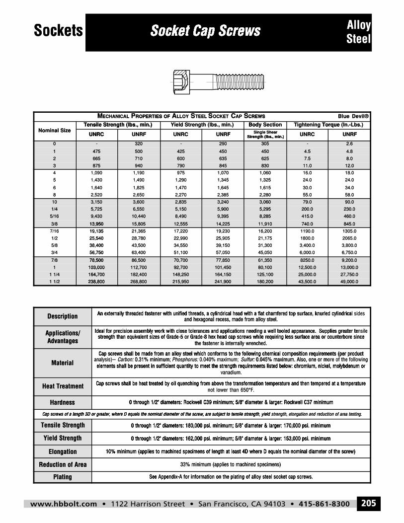
www.hbbolt.com • 1122 Harrison Street • San Francisco, CA 94103 • 415-861-8300 205
Sockets Socket Cap Screws AlloySteel
MECHANICAL PROPERTIES OF ALLOY STEEL SOCKET CAP SCREWS Blue Devil®
Nominal SizeTensile Strength (lbs., min.) Yield Strength (lbs., min.) Body Section Tightening Torque (In.-Lbs.)
UNRC UNRF UNRC UNRF Single ShearStrength (lbs., min.) UNRC UNRF
0 - 320 - 290 305 - 2.6
1 475 500 425 450 450 4.5 4.8
2 665 710 600 635 625 7.5 8.0
3 875 940 790 845 830 11.0 12.0
4 1,090 1,190 975 1,070 1,060 16.0 18.0
5 1,430 1,490 1,290 1,345 1,325 24.0 24.0
6 1,640 1,825 1,470 1,645 1,615 30.0 34.0
8 2,520 2,650 2,270 2,385 2,280 55.0 58.0
10 3,150 3,600 2,835 3,240 3,060 79.0 90.0
1/4 5,725 6,550 5,150 5,900 5,295 200.0 230.0
5/16 9,430 10,440 8,490 9,395 8,285 415.0 460.0
3/8 13,950 15,805 12,555 14,225 11,910 740.0 845.0
7/16 19,135 21,365 17,220 19,230 16,200 1190.0 1305.0
1/2 25,540 28,780 22,990 25,905 21,175 1800.0 2065.0
5/8 38,400 43,500 34,550 39,150 31,300 3,400.0 3,800.0
3/4 56,750 63,400 51,100 57,050 45,050 6,000.0 6,750.0
7/8 78,500 86,500 70,700 77,850 61,350 8250.0 9,200.0
1 103,000 112,700 92,700 101,450 80,100 12,500.0 13,000.0
1 1/4 164,700 182,400 148,250 164,150 125,100 25,000.0 27,750.0
1 1/2 238,800 268,800 215,950 241,900 180,200 43,500.0 49,000.0
Description An externally threaded fastener with unified threads, a cylindrical head with a flat chamfered top surface, knurled cylindrical sidesand hexagonal recess, made from alloy steel.
Applications/Advantages
Ideal for precision assembly work with close tolerances and applications needing a well tooled appearance. Supplies greater tensilestrength than equivalent sizes of Grade-5 or Grade-8 hex head cap screws while requiring less surface area or counterbore since
the fastener is internally wrenched.
MaterialCap screws shall be made from an alloy steel which conforms to the following chemical composition requirements (per product
analysis)-- Carbon: 0.31% minimum; Phosphorus: 0.040% maximum; Sulfur: 0.045% maximum. Also, one or more of the followingelements shall be present in sufficient quantity to meet the strength requirements listed below: chromium, nickel, molybdenum or
vanadium.
Heat Treatment Cap screws shall be heat treated by oil quenching from above the transformation temperature and then tempered at a temperaturenot lower than 650°F.
Hardness 0 through 1/2" diameters: Rockwell C39 minimum; 5/8" diameter & larger: Rockwell C37 minimum
Cap screws of a length 3D or greater, where D equals the nominal diameter of the screw, are subject to tensile strength, yield strength, elongation and reduction of area testing.
Tensile Strength 0 through 1/2" diameters: 180,000 psi. minimum; 5/8" diameter & larger: 170,000 psi. minimum
Yield Strength 0 through 1/2" diameters: 162,000 psi. minimum; 5/8" diameter & larger: 153,000 psi. minimum
Elongation 10% minimum (applies to machined specimens of length at least 4D where D equals the nominal diameter of the screw)
Reduction of Area 33% minimum (applies to machined specimens)
Plating See Appendix-A for information on the plating of alloy steel socket cap screws.
Sockets Socket Cap ScrewsSocket Cap ScrewsSocket Cap Screws AlloySockets Socket Cap ScrewsSocket Cap ScrewsSocket Cap Screws Steel
UNRC
Tensile Strength (lbs., min.)Nominal Size
0
1
2
3
6
5
4
UNRFUNRC
Tensile Strength (lbs., min.)
ROPERTIES OFPECHANICALM
- 320
475 500
665 710
875 940
1,8251,640
1,4901,430
1,1901,090
Strength (lbs., min.)UNRFUNRC
Body Yield Strength (lbs., min.)
CREWSSAPCOCKETSTEELSLLOYAROPERTIES OF
- 290
425 450
600 635
790 845
1,6451,470
1,3451,290
1,070975
UNRCStrength (lbs., min.)Single Shear
Torque Tightening SectionBody
CREWS
305 -
450 4.5
625 7.5
830 11.0
30.01,615
24.01,325
16.01,060
UNRF
(In.-Lbs.)Torque
Blue Devil®
2.6
4.8
8.0
12.0
34.0
24.0
18.0
8
10
1/4
5/16
3/8 13,950
56,7503/4
38,4005/8
25,5401/2
19,1357/16
7/8 78,500
1 103,000
2,6502,520
3,150 3,600
5,725 6,550
9,430 10,440
13,950 15,805
63,40056,750
43,50038,400
28,78025,540
21,36519,135
78,500 86,500
103,000 112,700
2,3852,270
2,835 3,240
5,150 5,900
8,490 9,395
12,555 14,225
57,05051,100
39,15034,550
25,90522,990
19,23017,220
70,700 77,850
92,700 101,450
55.02,280
3,060 79.0
5,295 200.0
8,285 415.0
11,910 740.0
6,000.045,050
3,400.031,300
1800.021,175
1190.016,200
61,350 8250.0
80,100 12,500.0
58.0
90.0
230.0
460.0
845.0
6,750.0
3,800.0
2065.0
1305.0
9,200.0
13,000.0
1 1/4 164,700
1 1/2 238,800
Description
AdvantagesApplications/
164,700 182,400
238,800 268,800
An externally threaded fastener with unified threads, a cylindrical head with a flat chamfered top surface, knurled cylindrical
strength than equivalent sizes of Grade-5 or Grade-8 hex head cap screws while requiring less surface area or counterbore sinceIdeal for precision assembly work with close tolerances and applications needing a well tooled appearance. Supplies greater te
148,250 164,150
215,950 241,900
and hexagonal recess, made from alloy steel.An externally threaded fastener with unified threads, a cylindrical head with a flat chamfered top surface, knurled cylindrical
the fastener is internally wrenched.strength than equivalent sizes of Grade-5 or Grade-8 hex head cap screws while requiring less surface area or counterbore since
Ideal for precision assembly work with close tolerances and applications needing a well tooled appearance. Supplies greater te
125,100 25,000.0
180,200 43,500.0
and hexagonal recess, made from alloy steel.An externally threaded fastener with unified threads, a cylindrical head with a flat chamfered top surface, knurled cylindrical
the fastener is internally wrenched.strength than equivalent sizes of Grade-5 or Grade-8 hex head cap screws while requiring less surface area or counterbore since
Ideal for precision assembly work with close tolerances and applications needing a well tooled appearance. Supplies greater te
27,750.0
49,000.0
sidesAn externally threaded fastener with unified threads, a cylindrical head with a flat chamfered top surface, knurled cylindrical
strength than equivalent sizes of Grade-5 or Grade-8 hex head cap screws while requiring less surface area or counterbore sincensileIdeal for precision assembly work with close tolerances and applications needing a well tooled appearance. Supplies greater te
Material
Heat Treatment
Hardness
Cap screws of a length 3D or greater, where D equals the nominal diameter of the screw, are subject to tensile strength, yield
Tensile Strength
elements shall be present in sufficient quantity to meet the strength requirements listed below: chromium, nickel, molybdenum o 0.31% minimum;Carbon:analysis)--
Cap screws shall be made from an alloy steel which conforms to the following chemical composition requirements (per product
Cap screws shall be heat treated by oil quenching from above the transformation temperature and then tempered at a temperature
Cap screws of a length 3D or greater, where D equals the nominal diameter of the screw, are subject to tensile strength, yield
0 through 1/2" diameters: Rockwell C39 minimum; 5/8" diameter & larger: Rockwell C37 minimum
0 through 1/2" diameters: 180,000 psi. minimum; 5/8" diameter & larger: 170,000 psi. minimum
vanadium.elements shall be present in sufficient quantity to meet the strength requirements listed below: chromium, nickel, molybdenum o
Sulfur: 0.040% maximum;Phosphorus:: 0.31% minimum;Cap screws shall be made from an alloy steel which conforms to the following chemical composition requirements (per product
°not lower than 650Cap screws shall be heat treated by oil quenching from above the transformation temperature and then tempered at a temperature
Cap screws of a length 3D or greater, where D equals the nominal diameter of the screw, are subject to tensile strength, yield
0 through 1/2" diameters: Rockwell C39 minimum; 5/8" diameter & larger: Rockwell C37 minimum
0 through 1/2" diameters: 180,000 psi. minimum; 5/8" diameter & larger: 170,000 psi. minimum
elements shall be present in sufficient quantity to meet the strength requirements listed below: chromium, nickel, molybdenum o 0.045% maximum. Also, one or more of the followingfur:
Cap screws shall be made from an alloy steel which conforms to the following chemical composition requirements (per product
F.°
Cap screws shall be heat treated by oil quenching from above the transformation temperature and then tempered at a temperature
strength, elongation and reduction of area testing.Cap screws of a length 3D or greater, where D equals the nominal diameter of the screw, are subject to tensile strength, yield
0 through 1/2" diameters: Rockwell C39 minimum; 5/8" diameter & larger: Rockwell C37 minimum
0 through 1/2" diameters: 180,000 psi. minimum; 5/8" diameter & larger: 170,000 psi. minimum
relements shall be present in sufficient quantity to meet the strength requirements listed below: chromium, nickel, molybdenum o 0.045% maximum. Also, one or more of the following
Cap screws shall be made from an alloy steel which conforms to the following chemical composition requirements (per product
Cap screws shall be heat treated by oil quenching from above the transformation temperature and then tempered at a temperature
strength, elongation and reduction of area testing.
0 through 1/2" diameters: Rockwell C39 minimum; 5/8" diameter & larger: Rockwell C37 minimum
0 through 1/2" diameters: 180,000 psi. minimum; 5/8" diameter & larger: 170,000 psi. minimum
Yield Strength
Elongation
Reduction of Area
Plating
0 through 1/2" diameters: 162,000 psi. minimum; 5/8" diameter & larger: 153,000 psi. minimum
10% minimum (applies to machined specimens of length at least 4D where D equals the nominal diameter of the screw)
See Appendix-A for information on the plating of alloy steel socket cap screws.
0 through 1/2" diameters: 162,000 psi. minimum; 5/8" diameter & larger: 153,000 psi. minimum
10% minimum (applies to machined specimens of length at least 4D where D equals the nominal diameter of the screw)
33% minimum (applies to machined specimens)
See Appendix-A for information on the plating of alloy steel socket cap screws.
0 through 1/2" diameters: 162,000 psi. minimum; 5/8" diameter & larger: 153,000 psi. minimum
10% minimum (applies to machined specimens of length at least 4D where D equals the nominal diameter of the screw)
hbbolt_pgs_193_224_17061_template_NEW_USE 2/8/16 11:16 AM Page 205
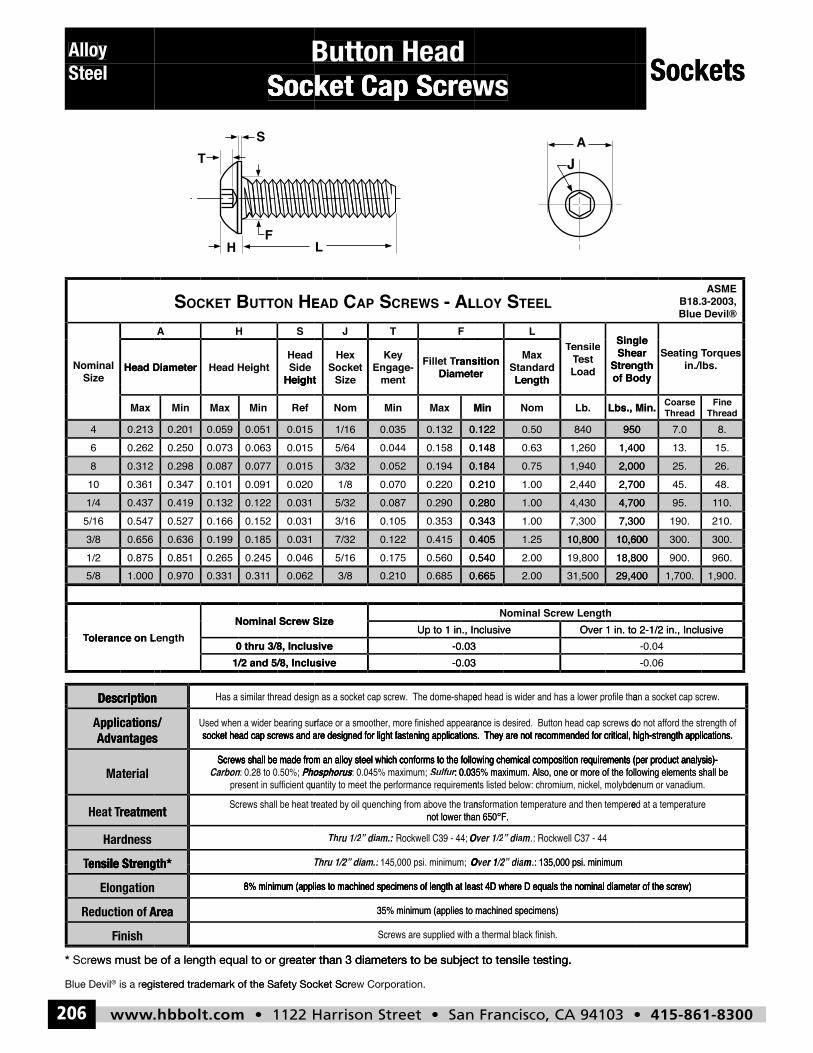
www.hbbolt.com • 1122 Harrison Street • San Francisco, CA 94103 • 415-861-8300206
Alloy Steel
Button HeadSocket Cap Screws
y Allo
Button Head
Button Head
Sockets
Steel
Socket Cap Screws
Socket Cap Screws
Socket Cap Screws
Sockets
Head DiameterSize
Nominal
E HNOTTU BTEKCOS
HeightSide Head
Head HeightHead Diameter
SHA
LA - SWERC SPACDAE
Diameterransition Fillet T
mentEngage-
Key
SizeSocket
Hex
Height
FTJ
LEET SYOLL
LengthStandard
Max
Diameterransition
of BodyStrength
Shear Single
Loadest TTest
ensile TTensile L
in./lbs.orques Seating T Torques
of BodyStrength
Shear Single
Blue Devil®B18.3-2003,
ASME
0.4370.5475/16
1/4
0.3120.36110
8
0.2130.2626
4
0.656
Max
3/8
0.0310.0310.1520.1660.527
0.1220.1320.419
0.0150.0200.0910.1010.347
0.0770.0870.298
0.0150.0150.0630.0730.250
0.0510.0590.201
0.031
RefMinMaxMin
Height
0.1850.1990.636
0.2800.2900.0875/32
0.1840.2100.2200.0701/8
0.1940.0523/32
0.1220.1480.1580.0445/64
0.1320.0351/16
0.405
MinMaxMinNom
0.4150.1227/320.3430.3530.1053/16
4,7004,4301.000.280
2,0002,7002,4401.000.210
1,9400.750.184
9501,4001,2600.630.148
8400.500.122
10,600
Lbs., Min.Lb.NomMin
Length
10,8001.250.4057,3007,3001.000.343
10.195.4,700
26.48.45.2,700
25.2,000
8.15.13.1,400
7.0950
300.
ThreadFine
ThreadCoarse Lbs., Min.
300.10,600210.190.7,300
Description
1.000
olerance on LTTolerance on Length
5/80.8751/2
Description
0.062
1/2 and 5/8, Inclusive0 thru 3/8, Inclusive
Nominal Screw Sizeolerance on Length
10.310.3310.9700.0460.2450.2650.851
0.665
-0.031/2 and 5/8, Inclusive-0.030 thru 3/8, Inclusive
Up to 1 in., InclusiveNominal Screw Size
0.6850.2103/80.5400.5600.1755/16
29,400
-0.03-0.03
Over 1 in. to 2-1/2 in., InclusiveUp to 1 in., InclusiveNominal Screw Length
31,5002.000.665
10,60018,80019,8002.000.540
10,800
1,900.
-0.06-0.04
Over 1 in. to 2-1/2 in., Inclusive
1,700.29,400960.900.18,800
Description
ensile StrengTTensile Strength*
Hardness
reatmentTHeat
Material
Advantagespplications/ A
ensile Strength*
reatment
Advantages
Phosphorus: 0.28 to 0.50%; CarbonScrews shall be made from an alloy steel which conforms to the following chemical composition requirements (per product analysis)-
socket head cap screws and are designed for light fastening applications. They are not recommended for critical, high-strength applications.pplications/
r:
145 000 psi minimum; Thru 1/2” diam.: :
Rockwell C39 - 44;
not lower than 650°F.
: 0.035% maximum. Also, one or more of the following elements shall be Sulfur: 0.045% maximum; PhosphorusScrews shall be made from an alloy steel which conforms to the following chemical composition requirements (per product analysis)-
socket head cap screws and are designed for light fastening applications. They are not recommended for critical, high-strength applications.
.: 135,000 psi. minimum
.: Rockwell C37 - 44
not lower than 650°F.
: 0.035% maximum. Also, one or more of the following elements shall be Screws shall be made from an alloy steel which conforms to the following chemical composition requirements (per product analysis)-
socket head cap screws and are designed for light fastening applications. They are not recommended for critical, high-strength applications.
inishF
AreaReduction of
Elongation
ensile StrengTTensile Strength*
ews must be of a length equal to or grScr*
egister is a r®Blue Devil
Area
ensile Strength*
8% minimum (applies to machined specimens of length at least 4D where D equals the nominal diameter of the screw)
eater than 3 diameters to be subject to tensile testing.ews must be of a length equal to or gr
ed trademark of the Safety Socket Scregister
35% minimum (applies to machined specimens)
8% minimum (applies to machined specimens of length at least 4D where D equals the nominal diameter of the screw)
145,000 psi. minimum; Thru 1/2” diam.: :
eater than 3 diameters to be subject to tensile testing.
ew Corporation. ed trademark of the Safety Socket Scr
35% minimum (applies to machined specimens)
8% minimum (applies to machined specimens of length at least 4D where D equals the nominal diameter of the screw)
.: 135,000 psi. minimum
eater than 3 diameters to be subject to tensile testing.
263
8% minimum (applies to machined specimens of length at least 4D where D equals the nominal diameter of the screw)
hbbolt_pgs_193_224_17061_template_NEW_USE 2/8/16 11:16 AM Page 206
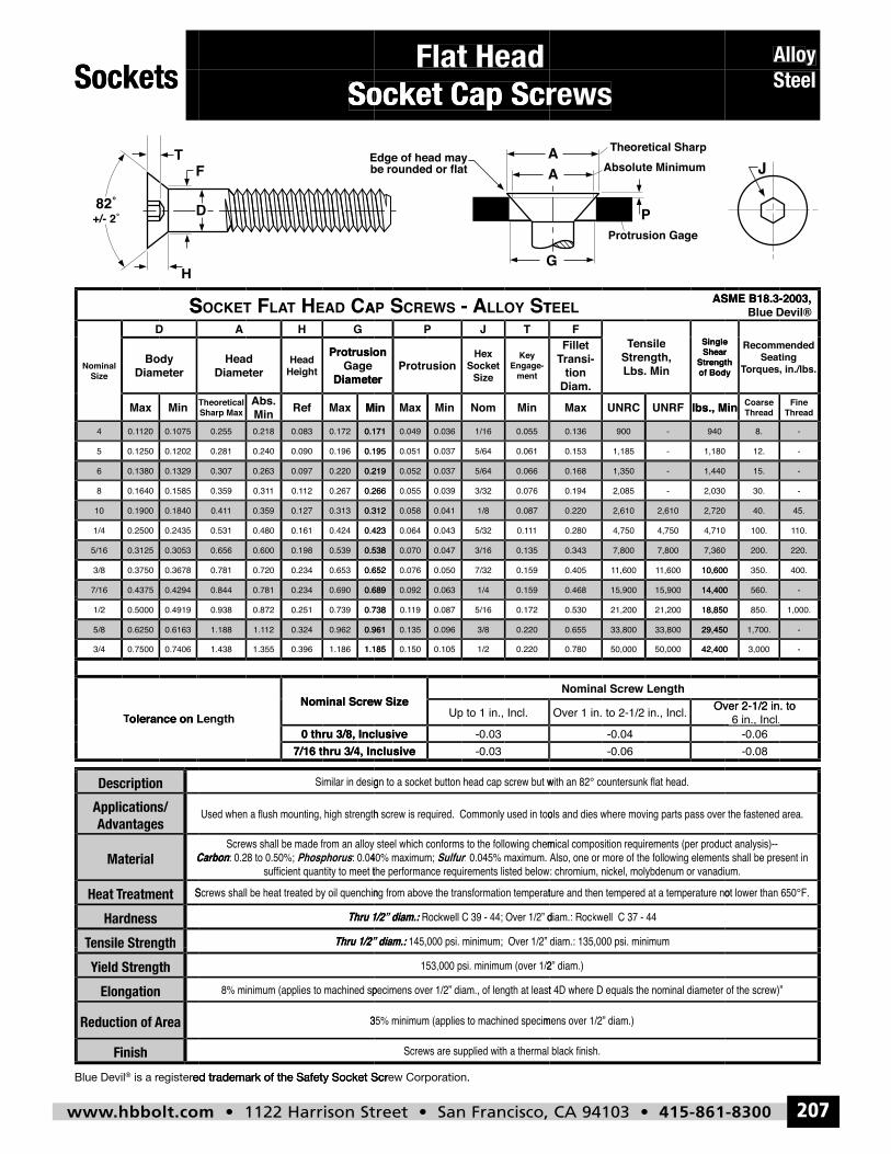
www.hbbolt.com • 1122 Harrison Street • San Francisco, CA 94103 • 415-861-8300 207
Alloy Steel
Flat HeadSocket Cap Screws
Sockets
Flat Head
y Allo
Sockets
Socket Cap Screws
Socket Cap Screws
Socket Cap Screws
Steel
S
MinMax
DiameterBody
D
SizeNominal
ACDAE HTAL FTEKCOS
MinMaxRefMinAbs.
Sharp MaxTheoretical
DiameterGage
Protrusion HeightHead
DiameterHead
GHA
T SYOLLA - SWERC SPA
MinNomMinMaxMin
ment-Engage
Key
SizeSocket
Hex Protrusion
Diameter
Protrusion
TJP
LEET
lbs., MinUNRFUNRCMax
Diam.tion
-ransiTFillet
of BodyStrength
Shear Single
Lbs. MinStrength,
ensile TTensile F
ASME B18.3-2003,
ThreadFine
ThreadCoarse lbs., Min
orques, in./lbs.TSeating
Recommended
of BodyStrength
Shear Single
Blue Devil®ASME B18.3-2003,
0.1329
0.15850.16408
0.13806
0.1075
0.12020.12505
1200.14
0.42940.43757/16
0.3053
0.36780.37503/8
0.31255/16
0.1840
0.24350.25001/4
0.190010
0.219
0.2660.267120.110.310.359
0.2200.0970.2630.307
0.171
0.1950.1960.0900.2400.281
0.1720.0830.2180.255
0.6890.6900.2340.7810.844
0.538
0.6520.6530.2340.7200.781
0.5390.1980.6000.656
0.312
0.4230.4240.1610.4800.531
0.3130.1270.35910.41
0.066
0.0763/320.0390.0550.266
5/640.0370.0520.219
0.055
0.0615/640.0370.0510.195
1/160.0360.0490.171
0.1591/40.0630.0920.689
0.135
0.1597/320.0500.0760.652
3/160.0470.0700.538
0.087
110.15/320.0430.0640.423
1/80.0410.0580.312
1,440
-2,0850.194
-1,3500.168
940
1,180-1,1850.153
-9000.136
14,40015,90015,9000.468
7,360
10,6001,60011,60010.405
7,8007,8000.343
2,720
4,7104,7504,7500.280
2,6102,6100.220
2,030
-15.
-
-12.
8.
-560.14,400
220.
400.350.10,600
200.
45.
10.1100.
40.
-30.
0.6163
0.74060.75003/4
0.62505/8
0.49190.50001/2
olerance on LTTolerance on Length
0.961
1.3551.438
0.9620.324121.11.188
0.7380.7390.2510.8720.938
7/16 thru 3/4, Inclusive0 thru 3/8, Inclusive
Nominal Screw Sizeolerance on Length
1.1851.1860.396
0.2203/80.0960.1350.961
0.1725/160.087190.10.738
-0.037/16 thru 3/4, Inclusive-0.030 thru 3/8, Inclusive
Up to 1 in., Incl.Nominal Screw Size
0.2201/20.1050.1501.185
29,45033,80033,8000.655
18,85021,20021,2000.530
-0.06-0.04
Over 2-1/2 in. toOver 1 in. to 2-1/2 in., Incl.
Nominal Screw Length
42,40050,00050,0000.780
, Incl.
-1,700.29,450
1,000.850.18,850
-0.08-0.06
6 in., Incl.Over 2-1/2 in. to
-3,00042,400
Description
ensile StrengthTTensile Strength
Hardness
reatmentTHeat
Material Carbon
Advantagespplications/ A
Thru 1/2” diam.:
Thru 1/2” diam.:
PhosphorusCarbon
r
Thru 1/2” diam.:
Thru 1/2” diam.:
Sulfur
264
inishF
AreaReduction of
Elongation
ield StrengthY
ensile StrengthTTensile Strength
ed trademark of the Safety Socket Scregister is a r®Blue Devil
ed trademark of the Safety Socket Scr
ew Corporation. ed trademark of the Safety Socket Scr
hbbolt_pgs_193_224_17061_template_NEW_USE 2/8/16 11:16 AM Page 207
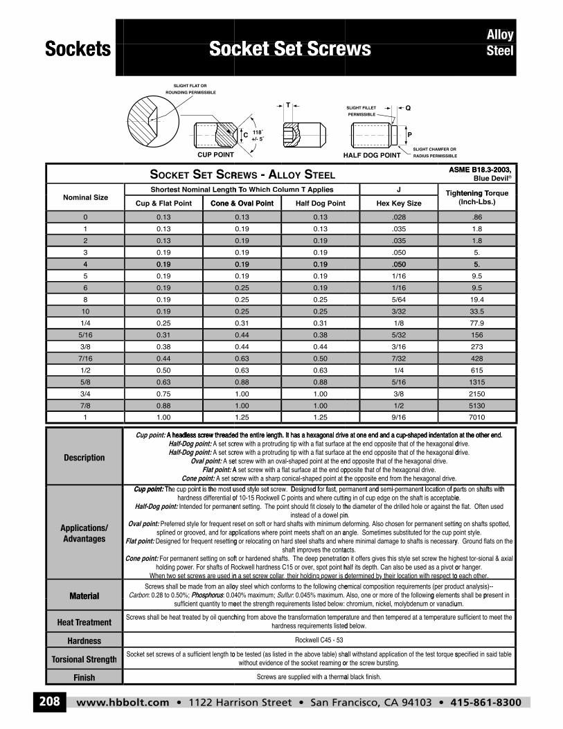
www.hbbolt.com • 1122 Harrison Street • San Francisco, CA 94103 • 415-861-8300208
Socket Set ScrewsAlloy SteelSockets Socket Set ScrewsSocket Set Screws
y AlloSockets Socket Set ScrewsSocket Set ScrewsSocket Set Screws Steel
4
23
01
Nominal Size
0.19
0.130.19
0.130.13
Cone & Oval PointCup & Flat Point
Shortest Nominal Length T
RC STE STEKCOS
0.190.19
0.190.190.19
0.19
0.130.130.19
0.13Half Dog PointCone & Oval Point
Applieso Which Column T h T To Which Column T
LEET SYOLLA - SWER
.050
.035
.050
.028
.035
Hex Key Sizeightening TTJ
ASME B18.3-2003,
5.
1.85.
.861.8
(Inch-Lbs.)orque htening T Torque
®Blue DevilASME B18.3-2003,
7/161/2
5/163/8
101/4
68
45
0.440.50
0.310.38
0.190.25
0.190.19
0.190.19
0.500.630.63
0.63
0.380.440.44
0.44
0.250.310.31
0.25
0.190.250.25
0.25
0.190.190.19
0.19
7/321/4
5/323/16
3/321/8
1/165/64
.0501/16
428615
156273
33.577.9
9.519.4
5.9.5
Description
7/81
5/83/4
Cup point:Cone point:
Flat point:Oval point:
Half-Dog point:Half-Dog point:
A headless screw threade Cup point: :
0.881.00
0.630.75
A headless screw threaded the entire length. It has a hexagonal drive at one end and a cup-shaped indentation at the other end.
1.001.251.25
1.00
0.881.001.00
0.88
A headless screw threaded the entire length. It has a hexagonal drive at one end and a cup-shaped indentation at the other end.
1/29/16
5/163/8
A headless screw threaded the entire length. It has a hexagonal drive at one end and a cup-shaped indentation at the other end.
51307010
13152150
Material
Advantagespplications/ A
Phosphorus
Cone point:
Flat point:
Oval point:
Half-Dog point:
Cup point:
266inishF
orsional StrengthTTorsional Strength
Hardness
reatmentTHeat
Material Phosphorus
hbbolt_pgs_193_224_17061_template_NEW_USE 2/8/16 11:16 AM Page 208
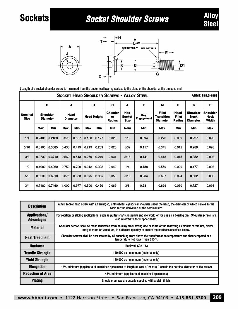
www.hbbolt.com • 1122 Harrison Street • San Francisco, CA 94103 • 415-861-8300 209
Sockets Socket Shoulder Screws AlloySteel
Description A hex socket head screw with an enlarged, unthreaded, cylindrical shoulder under the head, the diameter of which serves as thebasis for the derivation of the nominal size.
Applications/Advantages
For rotation or sliding applications, such as pulley shafts, in punch and die work, or for use as a bearing pin. Shoulder screws arealso referred to as "stripper bolts".
Material Shoulder screws shall be made fabricated from an alloy steel having one or more of the following elements: chromium, nickel,molybdenum or vanadium, in sufficient quantity to assure the hardness specified below.
Heat Treatment Shoulder screws shall be heat-treated by oil quenching from above the transformation temperature and then tempered at atemperature not lower than 650°F.
Hardness Rockwell C32 - 43
Tensile Strength 140,000 psi. minimum (material only)
Yield Strength 120,000 psi. minimum (material only)
Elongation 15% minimum (applies to all machined specimens of length at least 4D where D equals the nominal diameter of the screw)
Reduction of Area 45% minimum (applies to all machined specimens)
Plating Shoulder screws are usually supplied with a plain finish.
SOCKET HEAD SHOULDER SCREWS - ALLOY STEEL ASME B18.3-1988
NominalSize
D A H C J T M R K F
ShoulderDiameter
HeadDiameter
Head HeightChamfer
orRadius
HexSocket
Size
KeyEngagement
FilletTransitionDiameter
HeadFillet
Radius
ShoulderNeck
Diameter
ShoulderNeckWidth
Max Min Max Min Max Min Min Nom Min Max Min Min Max
1/4 0.2480 0.2460 0.375 0.357 0.188 0.177 0.020 1/8 0.094 0.276 0.009 0.227 0.093
5/16 0.3105 0.3085 0.438 0.419 0.219 0.209 0.026 5/32 0.117 0.345 0.012 0.289 0.093
3/8 0.3730 0.3710 0.562 0.543 0.250 0.240 0.031 3/16 0.141 0.413 0.015 0.352 0.093
1/2 0.4980 0.4960 0.750 0.729 0.312 0.302 0.040 1/4 0.188 0.550 0.020 0.477 0.093
5/8 0.6230 0.6210 0.875 0.853 0.375 0.365 0.050 5/16 0.234 0.687 0.024 0.602 0.093
3/4 0.7480 0.7460 1.000 0.977 0.500 0.490 0.069 3/8 0.281 0.826 0.030 0.727 0.093
J
AT
C
H
SEE DETAIL Y
K D
SEE DETAIL Z
G
E
D1
L±.005
Sockets Socket Shoulder ScrewsSocket Shoulder ScrewsSocket Shoulder Screws AlloySockets Socket Shoulder Screws
J
A
Socket Shoulder Screws
‡TH
SEE DETAIL Y
K D
SEE DETAIL Z
L±.005±L
Socket Shoulder Screws
SEE DETAIL Z
E
D1
SteelAlloy
‡Length of a socket shoulder screw is measured from the underhead bearing sur
D A
‡Length of a socket shoulder screw is measured from the underhead bearing sur
HA
HOULDERSEADHOCKETS
C
face to the plane of the shoulder at the threaded ‡Length of a socket shoulder screw is measured from the underhead bearing sur
HexChamfer
TJC
TEELSLLOY- ACREWSSHOULDER
C
K D
end.face to the plane of the shoulder at the threaded
ShoulderHeadFillet
KRM
ASME B18.3-1988TEEL
G
D1
ShoulderShoulder
FK
ASME B18.3-1988
MinMax
DiameterShoulder
SizeNominal
1/4 0.2480 0.2460
0.30850.31055/16
3/8 0.3730 0.3710
MinMaxMinMaxMin
Head HeightDiameter
HeadDiameterShoulder
0.2460 0.375 0.357 0.188 0.177
0.2090.2190.4190.4380.3085
0.3710 0.562 0.543 0.250 0.240
MinNomMinMin
EngagementKey
SizeSocket
Hex
Radiusor
ChamferHead Height
0.177 0.020 1/8 0.094
0.1175/320.0260.209
0.240 0.031 3/16 0.141
MinMinMax
DiameterNeck
Shoulder
RadiusFilletHead
DiameterTransition
Fillet
Engagement
0.094 0.276 0.009 0.227
0.2890.0120.3450.117
0.141 0.413 0.015 0.352
MaxMin
WidthNeck
Shoulder
DiameterNeck
Shoulder
0.227 0.093
0.0930.289
0.352 0.093
Description
0.49600.49801/2
5/8 0.6230 0.6210
0.74600.74803/4
A hex socket head screw with an enlarged, unthreaded, cylindrical shoulder under the head, the diameter of which serves as the
0.3020.3120.7290.7500.4960
0.6210 0.875 0.853 0.375 0.365
0.4900.5000.9771.0000.7460
A hex socket head screw with an enlarged, unthreaded, cylindrical shoulder under the head, the diameter of which serves as the
0.1881/40.0400.302
0.365 0.050 5/16 0.234
0.2813/80.0690.490
A hex socket head screw with an enlarged, unthreaded, cylindrical shoulder under the head, the diameter of which serves as the
0.4770.0200.5500.188
0.234 0.687 0.024 0.602
0.7270.0300.8260.281
A hex socket head screw with an enlarged, unthreaded, cylindrical shoulder under the head, the diameter of which serves as the
0.0930.477
0.602 0.093
0.0930.727
Description
AdvantagesApplications/
Material
Heat Treatment
Hardness
Tensile Strength
For rotation or sliding applications, such as pulley shafts, in punch and die work, or for use as a bearing pin. Shoulder scre
molybdenum or vanadium, in sufficient quantity to assure the hardness specified below.Shoulder screws shall be made fabricated from an alloy steel having one or more of the following elements: chromium, nickel,
Shoulder screws shall be heat-treated by oil quenching from above the transformation temperature and then tempered at a
basis for the derivation of the nominal size.
also referred to as "stripper bolts".For rotation or sliding applications, such as pulley shafts, in punch and die work, or for use as a bearing pin. Shoulder scre
molybdenum or vanadium, in sufficient quantity to assure the hardness specified below.Shoulder screws shall be made fabricated from an alloy steel having one or more of the following elements: chromium, nickel,
temperature not lower than 650Shoulder screws shall be heat-treated by oil quenching from above the transformation temperature and then tempered at a
Rockwell C32 - 43
140,000 psi. minimum (material only)
basis for the derivation of the nominal size.
also referred to as "stripper bolts".For rotation or sliding applications, such as pulley shafts, in punch and die work, or for use as a bearing pin. Shoulder scre
molybdenum or vanadium, in sufficient quantity to assure the hardness specified below.Shoulder screws shall be made fabricated from an alloy steel having one or more of the following elements: chromium, nickel,
F.°temperature not lower than 650Shoulder screws shall be heat-treated by oil quenching from above the transformation temperature and then tempered at a
Rockwell C32 - 43
140,000 psi. minimum (material only)
ws areFor rotation or sliding applications, such as pulley shafts, in punch and die work, or for use as a bearing pin. Shoulder scre
Shoulder screws shall be made fabricated from an alloy steel having one or more of the following elements: chromium, nickel,
Shoulder screws shall be heat-treated by oil quenching from above the transformation temperature and then tempered at a
Tensile Strength
Yield Strength
Elongation
Reduction of Area
Plating
15% minimum (applies to all machined specimens of length at least 4D where D equals the nominal diameter of the screw)
140,000 psi. minimum (material only)
120,000 psi. minimum (material only)
15% minimum (applies to all machined specimens of length at least 4D where D equals the nominal diameter of the screw)
45% minimum (applies to all machined specimens)
Shoulder screws are usually supplied with a plain finish.
140,000 psi. minimum (material only)
120,000 psi. minimum (material only)
15% minimum (applies to all machined specimens of length at least 4D where D equals the nominal diameter of the screw)
45% minimum (applies to all machined specimens)
Shoulder screws are usually supplied with a plain finish.
15% minimum (applies to all machined specimens of length at least 4D where D equals the nominal diameter of the screw)
hbbolt_pgs_193_224_17061_template_NEW_USE 2/8/16 11:16 AM Page 209
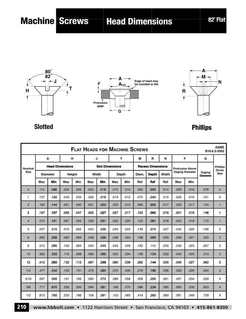
www.hbbolt.com • 1122 Harrison Street • San Francisco, CA 94103 • 415-861-8300210
Screws Head Dimensions
82º Flat
5
Machine
Screws
Head Dimensions
Head Dimensions
Flatº82
Machine
Screws
Head Dimensions
Head Dimensions
Flat82
A
5Slotted
JH
OFSDAE HTATLF
5
MT
SWERCSENIHCA MRO FNR
Phillips
G
B18.6.3-2002ASME
Phillips
.144
.167.1873
.1622
.096
.120.1371
12.10
MinMax
Diameter
Head DimensionsSize
Nominal
.023
.027.035.047.059.167
.031.040.051.144
.016
.019.026.033.043.120
.023.026.035.096
MinMaxMinMaxMin
idthWHeight
Slot DimensionsHead Dimensions
.055
.060.100.017.027.027
.096.015.023.023
.035
.043.070.012.019.019
.062.010.015.016
RefRefMinMaxMin
DepthDiam.Depth
Recess DimensionsSlot Dimensions
.017
.018.031.018.060
.029.017.055
.016
.016.028.015.043
.026.014.035
MinMaxRefRef
idthWDepth DiameterGaging Diameter
Above Protrusion Recess Dimensions
1
1.148
.124
0
0.101
.078
DiameterGaging Size
Driver Phillips
.333
.380.41212
.36210
.238
.285.3128
.2626
.191
.215.2375
.2124
.167.1873
.050
.056.06712.1.132.380
.060.09816.1.333
.039
.045.054.084.100.285
.048.069.083.238
.031
.035.043.062.075.215
.039.055.067.191
.027.035.047.059.167
.124
.144.262.039.060.056
.198.034.053.050
.094
.1.182.029.045.045
.168.024.038.039
.081
.074.148.022.034.035
.122.020.030.031
.060.100.017.027.027
.025
.027.045.035.144
.042.032.124
.021
.023.039.03010
.036.029.094
.019
.020.034.027.074
.032.018.081
.018.031.018.060
2
3.362
.313
2
2.267
.220
1
2.196
.172
1.148
62
.670
.765.8151/2
.7173/8
.442
.556.5975/16
.4771/4
.380.41212
.081
.091.106.186.223.765
.094.200.230.670
.064
.072.084.165.191.556
.075.131.153.442
.056.06712.1.132.380
.234
.265.418.065.103.091
.386.070.106.081
.160
.205.358.058.088.072
.276.046.070.064
.144.262.039.060.056
.039
.049.081.069.265
.065.065.234
.029
.034.057.061.205
.050.036.160
.027.045.035.144
4
4.739
.653
3
4.539
.424
3.362
hbbolt_pgs_193_224_17061_template_NEW_USE 2/8/16 11:16 AM Page 210
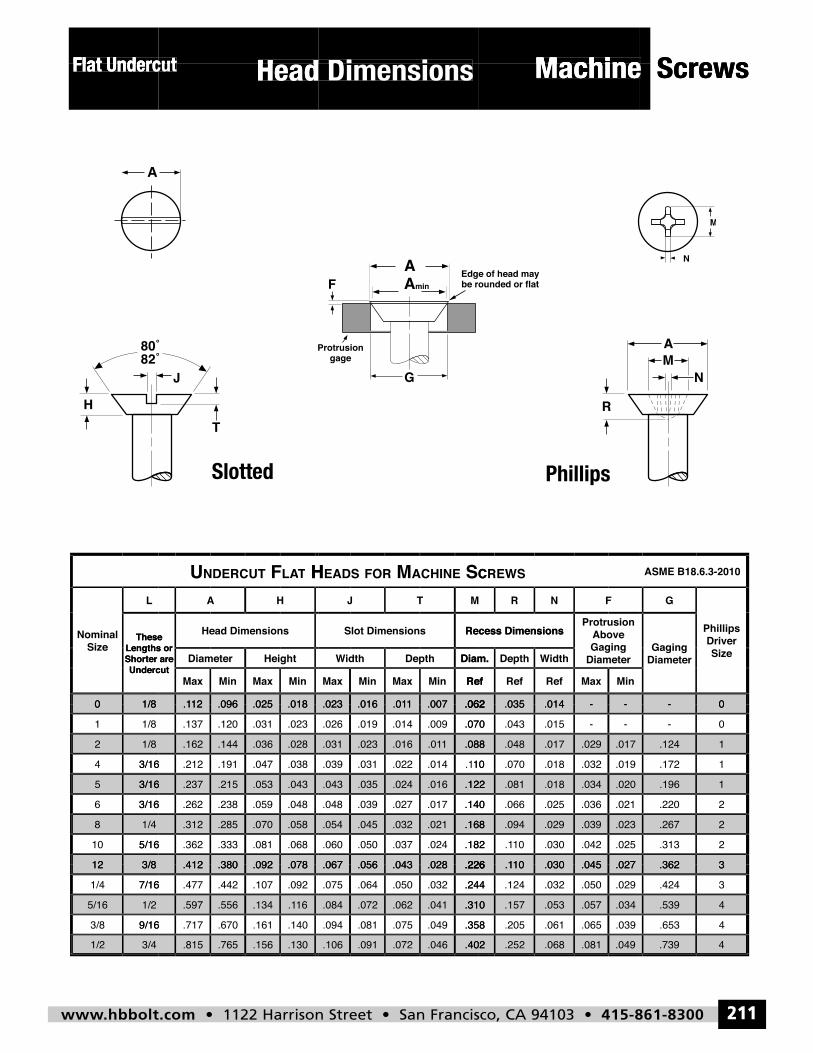
www.hbbolt.com • 1122 Harrison Street • San Francisco, CA 94103 • 415-861-8300 211
Machine Head DimensionsFlat Undercut
5
Flat Undercut
Head DimensionsFlat Undercut
Head Dimensions
Machine
Machine Screws
Flat Undercut
Head DimensionsFlat Undercut
Head Dimensions
Machine
Machine Screws
Slotted5
Phillips
1/80
UndercutShorter are Lengths or
These
L
SizeNominal
.018
HTATL FTUCREDNU
.025.09612.1
MinMaxMinMax
HeightDiameter
Head Dimensions
UndercutShorter are Lengths or
These
HA
.062
CSENIHCA MROFSDAE H
.0071.01.016.023
RefMinMaxMinMax
Diam.DepthidthW
Recess DimensionsSlot Dimensions
MTJ
-
SWERC
-.014.035.062
MinMaxRefRefRef
idthWDepthDiam. DiameterGaging Above
Protrusion Recess Dimensions
FNR
0-
DiameterGaging Size
Driver Phillips
G
ASME B18.6.3-2010
3/165
1/8
3/164
2
1/8
1/81
0
3/812
1/4
5/1610
8
3/166
.043.053.215.2373/16
.028
.038.047.191.2123/16
.036.144.162
.018
.023.031.120.137
.025.09612.1
.078.092.380.412
.058
.068.081.333.3625/16
.070.285.312
.048.059.238.2623/16
.122.016.024.035.043
.088
10.1.014.022.031.039
1.01.016.023.031
.062
.070.009.014.019.026
.0071.01.016.023
.226.028.043.056.067
.168
.182.024.037.050.060
.021.032.045.054
.140.017.027.039.048
.020.034.018.081.122
.017
.019.032.018.07010
.029.017.048.088
-
--.015.043.070
-.014.035.062
.027.045.03010.1.226
.023
.025.042.03010.1.182
.039.029.094.168
.021.036.025.066.140
.196
1
1.172
.124
0
0-
-
3.362
2
2.313
.267
1
2.220
3/41/2
1/2
9/163/8
5/16
3/8
7/161/4
12
.130.156.765.815
16
.140.161.670.7179/16
.1.134.556.597
.078
.092.107.442.4777/16
.092.380.412
.402.046.072.091.106
.310
.358.049.075.081.094
.041.062.072.084
.226
.244.032.050.064.075
.028.043.056.067
.081.068.252.402
.034
.039.065.061.205.358
.057.053.157.310
.027
.029.050.032.124.244
.045.03010.1.226
.049
63
4
4.653
.539
3
3.424
.362
4.739
hbbolt_pgs_193_224_17061_template_NEW_USE 2/8/16 11:16 AM Page 211
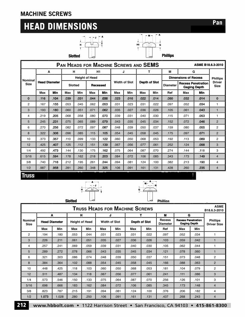
MACHINE SCREWS
HEAD DIMENSIONS
J A M A
PanCombo Pan
MACHINE SCREW
SMACHINE SCREW
HEAD DIMENSIONS
HEAD DIMENSIONSJ A
Combo Pan
H
M A
Combo PanPan
H1H
J
T G
A M A
5
H
J
T
A
H1
H1 G
M A
Slotted
Slotted5
Phillips
Phillips
AE HSSURTHA
RC SENIHCA MROFSDATJ
SWEGM
p
B18.6.3-2010ASME
.3848
.289
.32165
.226
.25743
.1942Max
Head DiameterSize
Nominal
.088.102.364
.066
.074.086.303.078.272
.051
.059.069.241.0611.21
.044.053.180MinMaxMin
Height of HeadHead Diameter
HA
.058.045.054
.045
.050.039.048.035.043
.036
.040.031.039.027.035
.031.023.031MaxMinMax
Depth of Slotidth of SlotW
TJ
.088.166.045
.078
.073.151.037.121.034
.059
.062.105.030.103.026
.052.097.022MaxRefMinGaging Depth
Recess Penetration DiameterRecess Depth of Slot
GM
2.063
12.048
.060
11.044
.0421.034
MinGaging Depth
Recess Penetration Driver Size
Phillips
1.5112
1.073
.44810
1/2
.698
.8233/85/16
.5731/4
18.1.134.487
.250
.10318.1.425
.2801.0281.073
.162
.191.215.787.183.666
.133.150.546
.077.056.067
.161
.068.050.060
.091.106
.106
.124.081.094.072.084
.087.064.075
11.1.241.061
.268
.104.181.053
.437.131
.173
.206.376.100.345.085
.126.256.070
694
2.079
.243
44.182
.148
33.101
.086
5
AJ
TH
M
GN
A
A
A
Slotted
5Slotted
AJ
H
T
M
GN
A
Phillips
www.hbbolt.com • 1122 Harrison Street • San Francisco, CA 94103 • 415-861-8300212
Machine Head Dimensions
Truss
5
Head Dimensions
Head Dimensions
Machine
Machine Screws
russTTruss
Head Dimensions
Head Dimensions
Machine
Machine Screws
.10416.10MinMax
Head Diameter
A
SizeNominal
.036
CA MROFSDAE HNAP
.044.031.039.104MinMaxMinMaxMin
RecessedSlotted
Height of HeadHead Diameter
H1H
.022
MSEDNASWERCSENIHC
.016.023.036MaxMinMaxMin
RecessedDepth of Slotidth of SlotW
TJ
.032
SM
.060.014MinMaxRefMin
Gaging DepthRecess Penetration Diameter
Dimensions of RecessDepth of Slot
GM
ASME B18.6.3-2010
P
0.014Min
Gaging DepthRecess Penetration
Dimensions of Recess
SizeDriver
Phillips
ASME B18.6.3-2010
P
.306.3228
.231
.256.2706.2455
.180
.205.2194.1933
.104
.155.167216.10
.407.42512
.357.37310
.10515.1.085.096.306
.079
.087.097.072.082.256.089.065.075.231
.062
.070.080.058.068.205.071.051.060.180
.036
.053.062.045.053.155.044.031.039.104
.139.15112.1.125.407
.122.133.09910.1.357
.054.105
.045
.050.039.048.087.035.043.079
.036
.040.031.039.070.027.035.062
.022
.031.023.031.053.016.023.036
.077.056.067.139
.058
.068.050.060.122.045
.046
.055.080.159.037.072.152.034
.043
.053.07115.1.030.061.105.026
.014
.034.052.097.022.032.060.014
.098.124.252.061
.071
.08913.1.192.053.097.175.045
22.055
.046
11.053
.043
01.034
.014
3.098
22.089
.071
.958.9871/2
.594
.716.7403/8.6155/16
.473.4921/4
.325.348.260.281.958
.203
.244.261.195.212.716.218.162.178.594
.162.175.130.144.473
.161.091.106.325
.106
.124.081.094.244.072.084.203
.087.064.075.162
.235.260.428.131
.149
.190.213.382.100.173.343.085
.1.144.274.070
4.235
44.190
.149318.1
hbbolt_pgs_193_224_17061_template_NEW_USE 2/8/16 11:16 AM Page 212
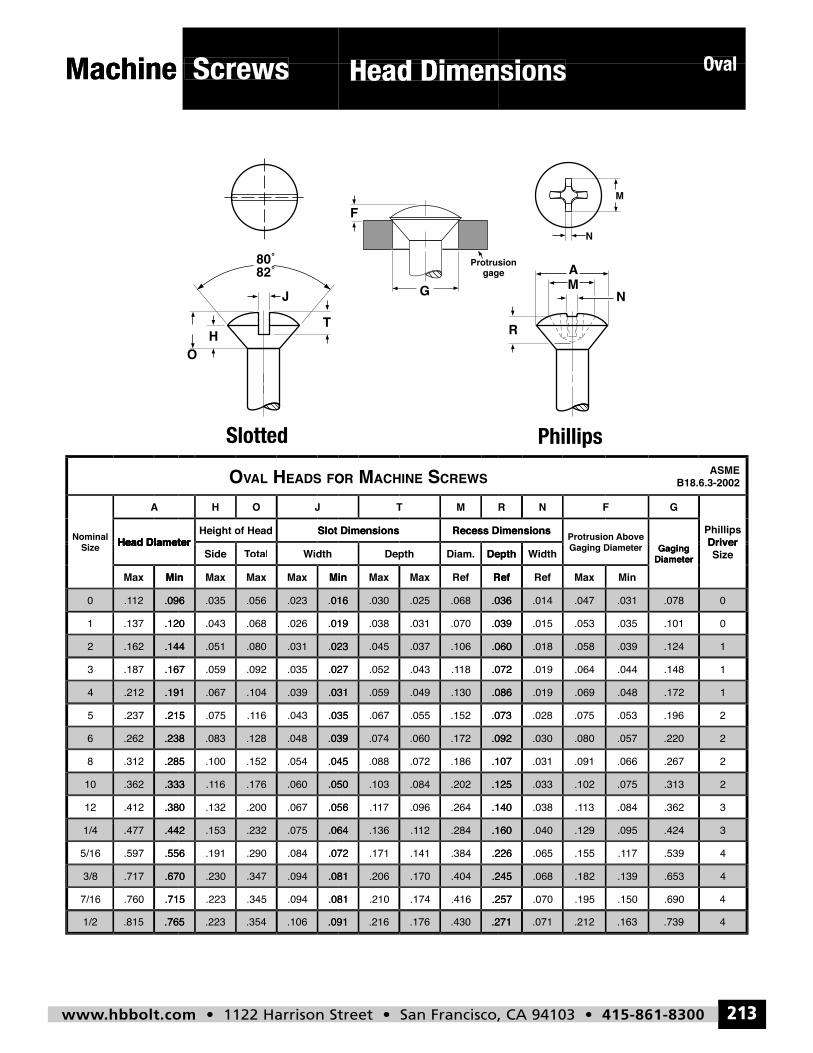
www.hbbolt.com • 1122 Harrison Street • San Francisco, CA 94103 • 415-861-8300 213
Screws Head Dimensions
5
OvalMachine
Screws
Head Dimensions
Head Dimensions
Oval
Machine
Screws
Head Dimensions
Head Dimensions
Oval
Head Diameter
A
Nominal
OFSDAE HLAVAO
Slot DimensionsHeight of HeadHead Diameter
JOH
Slotted5
SWERCSENIHCA MRO
Recess DimensionsSlot Dimensions
MT
Above Protrusion Recess Dimensions
FNR
Phillips
Driver Phillips
G
B18.6.3-2002ASME
.191.2124
.144
.167.1873
.1622
.096
.120.1371
12.10
MinMax
Head DiameterSize
.031.039.104.067.191
.023
.027.035.092.059.167
.031.080.051.144
.016
.019.026.068.043.120
.023.056.035.096
MinMaxMaxMaxMin
idthWotalTTotalSideHead Diameter
.086.130.049.059.031
.060
.07218.1.043.052.027
.106.037.045.023
.036
.039.070.031.038.019
.068.025.030.016
RefRefMaxMaxMin
DepthDiam.Depth
.048.069.019.086
.039
.044.064.019.072
.058.018.060
.031
.035.053.015.039
.047.014.036
MinMaxRefRef
idthWDepth DiameterGaging Gaging Diameter
1.172
1
1.148
.124
0
0.101
.078
DiameterGaging Size
Driver
.442
.215.2375
.556.5975/16
.4771/4
.333
.380.41212
.36210
.238
.285.3128
.2626
.064
.035.04316.1.075.215
.072.084.290.191.556
.075.232.153.442
.050
.056.067.200.132.380
.060.17616.1.333
.039
.045.054.152.100.285
.048.128.083.238
.160
.055.067.035
.226.384.141.171.072
.28412.1.136.064
.125
.140.264.09617.1.056
.202.084.103.050
.092
.107.186.072.088.045
.172.060.074.039
.073.152
.095
17.1.155.065.226
.129.040.160
.075
.08413.1.038.140
.102.033.125
.057
.066.091.031.107
.080.030.092
.053.075.028.073
3
4.539
.424
2
3.362
.313
2
2.267
.220
2.196
70
.670
.715.7607/16
.7173/8
.765.8151/2
.081
.081.094.345.223.715
.094.347.230.670
.091.106.354.223.765
.245
.257.416.174.210.081
.404.170.206.081
.271.430.176.216.091
.139
.150.195.070.257
.182.068.245
.163.212.071.271
4
.690
.653
4.739
4
hbbolt_pgs_193_224_17061_template_NEW_USE 2/8/16 11:16 AM Page 213
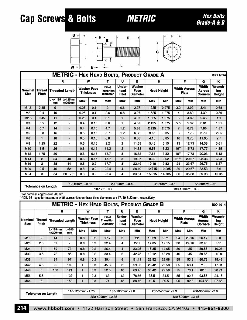
www.hbbolt.com • 1122 Harrison Street • San Francisco, CA 94103 • 415-861-8300214
Hex BoltsGrade-A & BCap Screws & Bolts METRIC
H
L
G
F
K
ET
RU
W
METRIC - HEX HEAD BOLTS, PRODUCT GRADE B ISO 4014
NominalSize
ThreadPitch
R W T U E H F G K
Threaded LengthWasher Face
Thickness
FilletTransitionDiameter
Under-headFillet
WasherFace
DiameterHead Height
Width AcrossFlats
WidthAcrossCorners
Wrench-ing
Height
L>125mm<=200mm
L>200mm Max Min Max Max Min Max Min Max Min Min Min
M16 2 44 - 0.8 0.2 17.7 3 22 10.29 9.71 24 23.16 26.17 6.8
M20 2.5 52 - 0.8 0.2 22.4 4 27.7 12.85 12.15 30 29.16 32.95 8.51
M24 3 60 73 0.8 0.2 26.4 4 33.25 15.35 14.65 36 35 39.55 10.26
M30 3.5 72 85 0.8 0.2 33.4 6 42.75 19.12 18.28 46 45 50.85 12.8
M36 4 84 97 0.8 0.2 39.4 6 51.11 22.92 22.08 55 53.8 60.79 15.46
M42 4.5 96 109 1 0.3 45.6 8 59.95 26.42 25.58 65 63.1 71.3 17.91
M48 5 108 121 1 0.3 52.6 10 69.45 30.42 29.58 75 73.1 82.6 20.71
M56 5.5 - 137 1 0.3 63 12 78.66 35.5 34.5 85 82.8 93.56 24.15
M64 6 - 153 1 0.3 71 13 88.16 40.5 39.5 95 92.8 104.86 27.65
Tolerance on Length110-120mm: ±1.75 130-180mm: ±2.0 200-240mm: ±2.3 260-300mm: ±2.6
320-400mm: ±2.85 420-500mm: ±3.15
METRIC - HEX HEAD BOLTS, PRODUCT GRADE A ISO 4014
NominalSize
ThreadPitch
R W T U E H F G K
Threaded LengthWasher Face
Thickness
FilletTransitionDiameter
Under-headFillet
WasherFace
DiameterHead Height
Width AcrossFlats
WidthAcrossCorners
Wrench-ing
Height
L <= 125mm
L>125mm<=200mm Max Min Max Max Min Max Min Max Min Min Min
M1.6 0.35 9 - 0.25 0.1 2 0.6 2.27 1.225 0.975 3.2 3.02 3.41 0.68
M2 0.4 10 - 0.25 0.1 2.6 0.8 3.07 1.525 1.275 4 3.82 4.32 0.89
M2.5 0.45 11 - 0.25 0.1 3.1 1 4.07 1.825 1.575 5 4.82 5.45 1.1
M3 0.5 12 - 0.4 0.15 3.6 1 4.57 2.125 1.875 5.5 5.32 6.01 1.31
M4 0.7 14 - 0.4 0.15 4.7 1.2 5.88 2.925 2.675 7 6.78 7.66 1.87
M5 0.8 16 - 0.5 0.15 5.7 1.2 6.88 3.65 3.35 8 7.78 8.79 2.35
M6 1 18 - 0.5 0.15 6.8 1.4 8.88 4.15 3.85 10 9.78 11.05 2.7
M8 1.25 22 - 0.6 0.15 9.2 2 11.63 5.45 5.15 13 12.73 14.38 3.61
M10 1.5 26 - 0.6 0.15 11.2 2 14.63 6.58 6.22 16** 15.73 17.77 4.35
M12 1.75 30 - 0.6 0.15 13.7 3 16.63 7.68 7.32 18** 17.73 20.03 5.12
M14 2 34 40 0.6 0.15 15.7 3 19.37 8.98 8.62 21** 20.67 23.36 6.03
M16 2 38 44 0.8 0.2 17.7 3 22.49 10.18 9.82 24 23.67 26.75 6.87
M20 2.5 46 52 0.8 0.2 22.4 4 28.19 12.715 12.285 30 29.67 33.53 8.6
M24 3 54 60 73* 0.8 0.2 26.4 4 33.61 15.215 14.785 36 35.38 39.98 10.35
Tolerance on Length12-16mm: ±0.35 20-30mm: ±0.42 35-50mm: ±0.5 55-80mm: ±0.6
90-120: ±0.7 130-150mm: ±0.8
Cap Screws & Bolts ws METRICMETRIC Hex BoltsCap Screws & Bolts ws
H
K
U
W
METRIC
L
ET
R
METRIC Grade-A & B
G
F
Grade-A & B
mmL <= 125
Threaded LengthPitch
ThreadSize
Nominal
METRIC
M1.6 0.35 9
100.4M2
KW
MinMax<=200mmL>125mm
mmL <= 125
DiameterTransition
ThicknessWasher Face
Threaded Length
R W
EADHEXH-METRIC
9 - 0.25 0.1
0.10.25-10
MaxMinMaxMax
Head HeightDiameter
FaceWasher
Fillethead
Under-
DiameterTransition
Fillet
EUT
RADEGRODUCT, POLTSB
2 0.6 2.27 1.225
1.5253.070.82.6
MinMaxMinMax
CornersAcrossWidth
FlatsWidth Across
Head Height
FH
ARADE
1.225 0.975 3.2 3.02 3.41
4.323.8241.2751.525
MinMin
Heighting
Wrench-
CornersAcrossWidth
KG
ISO 4014
3.41 0.68
0.894.32
M2.5 0.45 11
120.5M3
M4 0.7 14
160.8M5
M6 1 18
221.25M8
M10 1.5 26
301.75M12
M14 2 34
382M16
11 - 0.25 0.1
0.150.4-12
14 - 0.4 0.15
0.150.5-16
18 - 0.5 0.15
0.150.6-22
26 - 0.6 0.15
0.150.6-30
34 40 0.6 0.15
0.20.84438
3.1 1 4.07 1.825
2.1254.5713.6
4.7 1.2 5.88 2.925
3.656.881.25.7
6.8 1.4 8.88 4.15
5.4511.6329.2
11.2 2 14.63 6.58
7.6816.63313.7
15.7 3 19.37 8.98
10.1822.49317.7
1.825 1.575 5 4.82 5.45
6.015.325.51.8752.125
2.925 2.675 7 6.78 7.66
8.797.7883.353.65
4.15 3.85 10 9.78 11.05
14.3812.73135.155.45
6.58 6.22 16** 15.73 17.77
20.0317.7318**7.327.68
8.98 8.62 21** 20.67 23.36
26.7523.67249.8210.18
5.45 1.1
1.316.01
7.66 1.87
2.358.79
11.05 2.7
3.6114.38
17.77 4.35
5.1220.03
23.36 6.03
6.8726.75
**DIN 931 spec for maximum width across flats on these three diameters are 17, 19 & 22 mm, respectively*For nominal lengths over 200mm.
METRIC
M20 2.5 46
Tolerance on Length
543M24
**DIN 931 spec for maximum width across flats on these three diameters are 17, 19 & 22 mm, respectively*For nominal lengths over 200mm.
R W
EADHEXH-METRIC
46 52 0.8 0.2
Tolerance on Length
0.20.860 73*54
0.35±12-16mm:
90-120:
**DIN 931 spec for maximum width across flats on these three diameters are 17, 19 & 22 mm, respectively
EUT
RADEGRODUCT, POLTSB
22.4 4 28.19 12.715
15.21533.61426.4
0.42±20-30mm:
0.7±90-120:
.**DIN 931 spec for maximum width across flats on these three diameters are 17, 19 & 22 mm, respectively
FH
BRADE
12.715 12.285 30 29.67 33.53
39.9835.383614.78515.215
0.5±35-50mm: 55-80mm:
0.8±130-150mm:
KG
ISO 4014
33.53 8.6
10.3539.98
0.6±55-80mm:
<=200mmL>125mm
Threaded LengthPitch
ThreadSize
Nominal
M16 2 44
522.5M20
M24 3 60
723.5M30
M36 4 84
MinMaxmmL>200
<=200mmL>125mm
DiameterTransition
ThicknessWasher Face
Threaded Length
44 - 0.8 0.2
0.20.8-52
60 73 0.8 0.2
0.20.88572
84 97 0.8 0.2
MaxMinMaxMax
Head HeightDiameter
FaceWasher
Fillethead
Under-
DiameterTransition
Fillet
17.7 3 22 10.29
12.8527.7422.4
26.4 4 33.25 15.35
19.1242.75633.4
39.4 6 51.11 22.92
MinMaxMinMax
CornersAcrossWidth
FlatsWidth Across
Head Height
10.29 9.71 24 23.16 26.17
32.9529.163012.1512.85
15.35 14.65 36 35 39.55
50.85454618.2819.12
22.92 22.08 55 53.8 60.79
MinMin
Heighting
Wrench-
CornersAcrossWidth
26.17 6.8
8.5132.95
39.55 10.26
12.850.85
60.79 15.46
964.5M42
M48 5 108
5.5M56
M64 6
Tolerance on Length
0.3110996
108 121 1 0.3
0.31137-
- 153 1 0.3
1.75±110-120mm: Tolerance on Length
320-400mm:
26.4259.95845.6
52.6 10 69.45 30.42
35.578.661263
71 13 88.16 40.5
2.0±130-180mm:
2.85±320-400mm:
71.363.16525.5826.42
30.42 29.58 75 73.1 82.6
93.5682.88534.535.5
40.5 39.5 95 92.8 104.86
260-300mm: 2.3±200-240mm:
3.15±420-500mm:
17.9171.3
82.6 20.71
24.1593.56
104.86 27.65
2.6±260-300mm:
hbbolt_pgs_193_224_17061_template_NEW_USE 2/8/16 11:17 AM Page 214
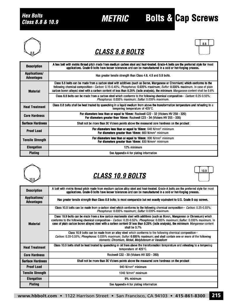
www.hbbolt.com • 1122 Harrison Street • San Francisco, CA 94103 • 415-861-8300 215
Bolts & Cap ScrewsMETRICHex BoltsClass 8.8 & 10.9
10.9
10.9
8.8
8.8
Description A hex bolt with metric thread pitch made from medium carbon steel and heat-treated. Grade-A bolts are the preferred style for mostapplications. Grade-B bolts have looser tolerances and can be manufactured in a cold or hot-forging process.
Applications/Advantages
Has greater tensile strength than Class 4.6, 4.8 and 5.8 bolts.
Material
Class 8.8 bolts can be made from a carbon steel with additives (such as Boron, Manganese or Chromium) which conforms to thefollowing chemical composition-- Carbon: 0.15-0.40%; Phosphorus: 0.035% maximum; Sulfur: 0.035% maximum. In case of plain
carbon boron alloyed steel with a carbon content of less than 0.25% (ladle analysis), the minimum Manganese content shall be 0.6%
Class 8.8 bolts can be made from a carbon steel which conforms to the following chemical composition-- Carbon: 0.25-0.55%;Phosphorus: 0.035% maximum; Sulfur: 0.035% maximum.
Heat Treatment Class 8.8 bolts shall be heat treated by quenching in a liquid medium from above the transformation temperature and reheating to atempering temperature of 425°C.
Core Hardness For diameters less than or equal to 16mm: Rockwell C22 - 32 (Vickers HV 250 - 320)For diameters greater than 16mm: Rockwell C23 - 34 (Vickers HV 255 - 335)
Surface Hardness Shall not be more than 30 Vickers points above the measured core hardness on the product
Proof Load For diameters less than or equal to 16mm: 640 N/mm2 minimumFor diameters greater than 16mm: 660 N/mm2 minimum
Tensile Strength For diameters less than or equal to 16mm: 800 N/mm2 minimumFor diameters greater than 16mm: 830 N/mm2 minimum
Elongation 12% minimum
Plating See Appendix-A for plating information
Description A bolt with metric thread pitch made from medium carbon alloy steel and heat-treated. Grade-A bolts are the preferred style for mostapplications. Grade-B bolts have looser tolerances and can be manufactured in a cold or hot-forging process.
Applications/Advantages
Has greater tensile strength than Class 8.8 bolts; is most comparable but not exactly equivalent to U.S. Grade 8 cap screws.
Material
Class 10.9 bolts can be made from a carbon steel which conforms to the following chemical composition-- Carbon: 0.25-0.55%;Phosphorus: 0.035% maximum; Sulfur: 0.035% maximum.
Class 10.9 bolts can be made from a low carbon martensite steel with additives (such as Boron, Manganese or Chromium) whichconforms to the following chemical composition-- Carbon: 0.20-0.55%; Phosphorus: 0.035% maximum; Sulfur: 0.035% maximum. Incase of plain carbon boron alloyed steel with a carbon content 0f less than 0.25% (ladle analysis), the minimum Manganese content
shall be 0.7%
Class 10.9 bolts can be made from an alloy steel which conforms to the following chemical composition--Carbon: 0.20-0.55%; Phosphorus: 0.035% maximum; Sulfur: 0.035% maximum; and shall contain one or more of the following
elements: Chromium, Nickel, Molybdenum or Vanadium
Heat TreatmentClass 10.9 bolts shall be heat treated by quenching in oil from above the transformation temperature and reheating to a tempering
temperature of 425°C.
Core Hardness Rockwell C32 - 39 (Vickers HV 320 - 380)
Surface Hardness Shall not be more than 30 Vickers points above the measured core hardness on the product
Proof Load 940 N/mm2 minimum
Tensile Strength 1040 N/mm2 minimum
Elongation 9% minimum
Plating See Appendix-A for plating information
Hex Bolts METRIC Bolts & Cap ScrewsCap ScrewsClass 8.8 & 10.9
8.8
Description
Class 8.8 & 10.9
A hex bolt with metric thread pitch made from medium carbon steel and heat-treated. Grade-A bolts are the preferred style for m
METRIC
CLASS 8.8 BOLTS
A hex bolt with metric thread pitch made from medium carbon steel and heat-treated. Grade-A bolts are the preferred style for m
Bolts & Cap Screws
TS
A hex bolt with metric thread pitch made from medium carbon steel and heat-treated. Grade-A bolts are the preferred style for m
Cap Screws
8.8
ostA hex bolt with metric thread pitch made from medium carbon steel and heat-treated. Grade-A bolts are the preferred style for mDescription
AdvantagesApplications/
Material
Heat Treatment
applications. Grade-B bolts have looser tolerances and can be manufactured in a cold or hot-forging process.A hex bolt with metric thread pitch made from medium carbon steel and heat-treated. Grade-A bolts are the preferred style for m
Class 8.8 bolts can be made from a carbon steel which conforms to the following chemical composition--
carbon boron alloyed steel with a carbon content of less than 0.25% (ladle analysis), the minimumfollowing chemical composition--Class 8.8 bolts can be made from a carbon steel with additives (such as Boron, Manganese or Chromium) which conforms to the
Class 8.8 bolts shall be heat treated by quenching in a liquid medium from above the transformation temperature and reheating t
applications. Grade-B bolts have looser tolerances and can be manufactured in a cold or hot-forging process.A hex bolt with metric thread pitch made from medium carbon steel and heat-treated. Grade-A bolts are the preferred style for m
Has greater tensile strength than Class 4.6, 4.8 and 5.8 bolts.
Sulfur:0.035% maximum;Phosphorus:Class 8.8 bolts can be made from a carbon steel which conforms to the following chemical composition--
carbon boron alloyed steel with a carbon content of less than 0.25% (ladle analysis), the minimum0.035% maximum;Phosphorus: 0.15-0.40%;Carbon:following chemical composition--
Class 8.8 bolts can be made from a carbon steel with additives (such as Boron, Manganese or Chromium) which conforms to the
tempering temperature of 425Class 8.8 bolts shall be heat treated by quenching in a liquid medium from above the transformation temperature and reheating t
applications. Grade-B bolts have looser tolerances and can be manufactured in a cold or hot-forging process.A hex bolt with metric thread pitch made from medium carbon steel and heat-treated. Grade-A bolts are the preferred style for m
Has greater tensile strength than Class 4.6, 4.8 and 5.8 bolts.
0.035% maximum.ulfur:: Carbon:Class 8.8 bolts can be made from a carbon steel which conforms to the following chemical composition--
Manganesecarbon boron alloyed steel with a carbon content of less than 0.25% (ladle analysis), the minimum 0.035% maxi Sulfur:: 0.035% maximum;
Class 8.8 bolts can be made from a carbon steel with additives (such as Boron, Manganese or Chromium) which conforms to the
C.°tempering temperature of 425Class 8.8 bolts shall be heat treated by quenching in a liquid medium from above the transformation temperature and reheating t
applications. Grade-B bolts have looser tolerances and can be manufactured in a cold or hot-forging process.ostA hex bolt with metric thread pitch made from medium carbon steel and heat-treated. Grade-A bolts are the preferred style for m
0.25-0.55%;Carbon::
content shall be 0.6%ee 0.035% maximum. In case of plain
Class 8.8 bolts can be made from a carbon steel with additives (such as Boron, Manganese or Chromium) which conforms to the
o aClass 8.8 bolts shall be heat treated by quenching in a liquid medium from above the transformation temperature and reheating t
Core Hardness
Surface Hardness
Proof Load
Tensile Strength
Elongation
Plating
For diameters greater than 16mm:For diameters less than or equal to 16mm:
Surface Hardness Shall not be more than 30 Vickers points above the measured core hardness on the product
For diameters less than or equal to 16mm:
For diameters less than or equal to 16mm:
Rockwell C23 - 34 (Vickers HV 255 - 335)For diameters greater than 16mm: Rockwell C22 - 32 (Vickers HV 250 - 320)For diameters less than or equal to 16mm:
Shall not be more than 30 Vickers points above the measured core hardness on the product
For diameters greater than 16mm:For diameters less than or equal to 16mm:
For diameters greater than 16mm:For diameters less than or equal to 16mm:
12% minimum
See Appendix-A for plating information
Rockwell C23 - 34 (Vickers HV 255 - 335) Rockwell C22 - 32 (Vickers HV 250 - 320)
Shall not be more than 30 Vickers points above the measured core hardness on the product
minimum2 660 N/mmFor diameters greater than 16mm: minimum2 640 N/mmFor diameters less than or equal to 16mm:
minimum2 830 N/mmFor diameters greater than 16mm: minimum2 800 N/mmFor diameters less than or equal to 16mm:
12% minimum
See Appendix-A for plating information
Shall not be more than 30 Vickers points above the measured core hardness on the product
10.9
Description
AdvantagesApplications/
applications. Grade-B bolts have looser tolerances and can be manufactured in a cold or hot-forging process.A bolt with metric thread pitch made from medium carbon alloy steel and heat-treated.
Has greater tensile strength than Class 8.8 bolts; is most comparable but not exactly equivalent to U.S. Grade 8 cap screws.
CLASS 10.9 BOLTS
applications. Grade-B bolts have looser tolerances and can be manufactured in a cold or hot-forging process.A bolt with metric thread pitch made from medium carbon alloy steel and heat-treated.
Has greater tensile strength than Class 8.8 bolts; is most comparable but not exactly equivalent to U.S. Grade 8 cap screws.
TS
applications. Grade-B bolts have looser tolerances and can be manufactured in a cold or hot-forging process.Grade-A bolts are the preferred style for A bolt with metric thread pitch made from medium carbon alloy steel and heat-treated.
Has greater tensile strength than Class 8.8 bolts; is most comparable but not exactly equivalent to U.S. Grade 8 cap screws.
10.9
applications. Grade-B bolts have looser tolerances and can be manufactured in a cold or hot-forging process.mostGrade-A bolts are the preferred style for
Has greater tensile strength than Class 8.8 bolts; is most comparable but not exactly equivalent to U.S. Grade 8 cap screws.
Material
Heat Treatment
Phosphorus: 0.20-0.55%;Carbon:Class 10.9 bolts can be made from an alloy steel
case of plain carbon boron alloyed steel with a carbon content 0f less than 0.25% (ladle analysis), the minimumconforms to the following chemical composition--
Class 10.9 bolts can be made from a low carbon martensite steel with additives (such as Boron, Manganese or Chromium) which
Class 10.9 bolts can be made from a carbon steel which conforms to the following chemical composition--
Class 10.9 bolts shall be heat treated by quenching in oil from above the transformation temperature and reheating to a temperi
Chromium, Nickel, Molybdenum or Vanadiumelements: 0.035% maximum; and shall contain one or more of the followingSulfur:: 0.035% maximum;Phosphorus:
conforms which Class 10.9 bolts can be made from an alloy steel
shall be 0.7%case of plain carbon boron alloyed steel with a carbon content 0f less than 0.25% (ladle analysis), the minimum
Phosphorus: 0.20-0.55%;Carbon:conforms to the following chemical composition--Class 10.9 bolts can be made from a low carbon martensite steel with additives (such as Boron, Manganese or Chromium) which
Sulfur:0.035% maximum;Phosphorus:Class 10.9 bolts can be made from a carbon steel which conforms to the following chemical composition--
temperature of 425Class 10.9 bolts shall be heat treated by quenching in oil from above the transformation temperature and reheating to a temperi
Chromium, Nickel, Molybdenum or Vanadium 0.035% maximum; and shall contain one or more of the following
composition--chemical following the to conforms
shall be 0.7%case of plain carbon boron alloyed steel with a carbon content 0f less than 0.25% (ladle analysis), the minimum
Sulfur:0.035% maximum;Phosphorus:Class 10.9 bolts can be made from a low carbon martensite steel with additives (such as Boron, Manganese or Chromium) which
0.035% maximum.ulfur:: Class 10.9 bolts can be made from a carbon steel which conforms to the following chemical composition--
C.°temperature of 425Class 10.9 bolts shall be heat treated by quenching in oil from above the transformation temperature and reheating to a temperi
0.035% maximum; and shall contain one or more of the followingcomposition--
contentManganesecase of plain carbon boron alloyed steel with a carbon content 0f less than 0.25% (ladle analysis), the minimum 0.035% maximum. InSulfur:
Class 10.9 bolts can be made from a low carbon martensite steel with additives (such as Boron, Manganese or Chromium) which
0.25-0.55%;Carbon:
ngClass 10.9 bolts shall be heat treated by quenching in oil from above the transformation temperature and reheating to a temperi
Core Hardness
Surface Hardness
Proof Load
Tensile Strength
Elongation
Plating
Surface Hardness Shall not be more than 30 Vickers points above the measured core hardness on the product
Rockwell C32 - 39 (Vickers HV 320 - 380)
Shall not be more than 30 Vickers points above the measured core hardness on the product
minimum2940 N/mm
minimum2N/mm1040
9% minimum
See Appendix-A for plating information
Rockwell C32 - 39 (Vickers HV 320 - 380)
Shall not be more than 30 Vickers points above the measured core hardness on the product
minimum
minimum
9% minimum
See Appendix-A for plating information
Shall not be more than 30 Vickers points above the measured core hardness on the product
hbbolt_pgs_193_224_17061_template_NEW_USE 2/8/16 11:17 AM Page 215
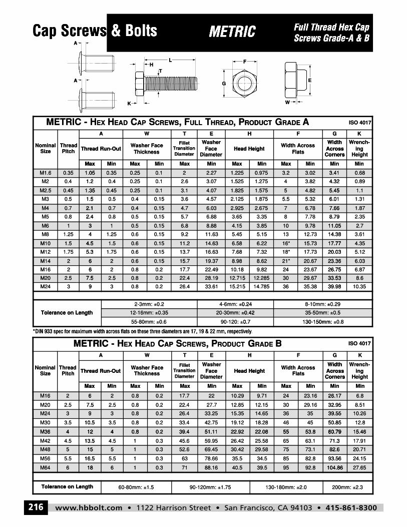
www.hbbolt.com • 1122 Harrison Street • San Francisco, CA 94103 • 415-861-8300216
Full Thread Hex CapScrews Grade-A & BCap Screws & Bolts METRIC
HL
G
F
A
K W
E
T
A
METRIC - HEX HEAD CAP SCREWS, PRODUCT GRADE B ISO 4017
NominalSize
ThreadPitch
A W T E H F G K
Thread Run-OutWasher Face
Thickness
FilletTransitionDiameter
WasherFace
DiameterHead Height
Width AcrossFlats
WidthAcrossCorners
Wrench-ing
Height
Max Min Max Min Max Min Max Min Max Min Min Min
M16 2 6 2 0.8 0.2 17.7 22 10.29 9.71 24 23.16 26.17 6.8
M20 2.5 7.5 2.5 0.8 0.2 22.4 27.7 12.85 12.15 30 29.16 32.95 8.51
M24 3 9 3 0.8 0.2 26.4 33.25 15.35 14.65 36 35 39.55 10.26
M30 3.5 10.5 3.5 0.8 0.2 33.4 42.75 19.12 18.28 46 45 50.85 12.8
M36 4 12 4 0.8 0.2 39.4 51.11 22.92 22.08 55 53.8 60.79 15.46
M42 4.5 13.5 4.5 1 0.3 45.6 59.95 26.42 25.58 65 63.1 71.3 17.91
M48 5 15 5 1 0.3 52.6 69.45 30.42 29.58 75 73.1 82.6 20.71
M56 5.5 16.5 5.5 1 0.3 63 78.66 35.5 34.5 85 82.8 93.56 24.15
M64 6 18 6 1 0.3 71 88.16 40.5 39.5 95 92.8 104.86 27.65
Tolerance on Length 60-80mm: ±1.5 90-120mm: ±1.75 130-180mm: ±2.0 200mm: ±2.3
METRIC - HEX HEAD CAP SCREWS, FULL THREAD, PRODUCT GRADE A ISO 4017
NominalSize
ThreadPitch
A W T E H F G K
Thread Run-OutWasher Face
Thickness
FilletTransitionDiameter
WasherFace
DiameterHead Height
Width AcrossFlats
WidthAcrossCorners
Wrench-ing
Height
Max Min Max Min Max Min Max Min Max Min Min Min
M1.6 0.35 1.05 0.35 0.25 0.1 2 2.27 1.225 0.975 3.2 3.02 3.41 0.68
M2 0.4 1.2 0.4 0.25 0.1 2.6 3.07 1.525 1.275 4 3.82 4.32 0.89
M2.5 0.45 1.35 0.45 0.25 0.1 3.1 4.07 1.825 1.575 5 4.82 5.45 1.1
M3 0.5 1.5 0.5 0.4 0.15 3.6 4.57 2.125 1.875 5.5 5.32 6.01 1.31
M4 0.7 2.1 0.7 0.4 0.15 4.7 6.03 2.925 2.675 7 6.78 7.66 1.87
M5 0.8 2.4 0.8 0.5 0.15 5.7 6.88 3.65 3.35 8 7.78 8.79 2.35
M6 1 3 1 0.5 0.15 6.8 8.88 4.15 3.85 10 9.78 11.05 2.7
M8 1.25 4 1.25 0.6 0.15 9.2 11.63 5.45 5.15 13 12.73 14.38 3.61
M10 1.5 4.5 1.5 0.6 0.15 11.2 14.63 6.58 6.22 16* 15.73 17.77 4.35
M12 1.75 5.3 1.75 0.6 0.15 13.7 16.63 7.68 7.32 18* 17.73 20.03 5.12
M14 2 6 2 0.6 0.15 15.7 19.37 8.98 8.62 21* 20.67 23.36 6.03
M16 2 6 2 0.8 0.2 17.7 22.49 10.18 9.82 24 23.67 26.75 6.87
M20 2.5 7.5 2.5 0.8 0.2 22.4 28.19 12.715 12.285 30 29.67 33.53 8.6
M24 3 9 3 0.8 0.2 26.4 33.61 15.215 14.785 36 35.38 39.98 10.35
Tolerance on Length
2-3mm: ±0.2 4-6mm: ±0.24 8-10mm: ±0.29
12-16mm: ±0.35 20-30mm: ±0.42 35-50mm: ±0.5
55-80mm: ±0.6 90-120: ±0.7 130-150mm: ±0.8
Cap Screws & Bolts ws METRICMETRIC Full Thread Hex CapFull Thread Hex CapCap Screws A
A
& Bolts ws
HL
K
T
METRIC
L
G
F
METRIC Screws Grade-A & B
W
E
Screws Grade-A & BFull Thread Hex Cap
Max
Thread Run-OutPitchThread
SizeNominal
-METRIC
M1.6 0.35 1.05
1.20.4M2
M2.5 0.45 1.35
MinMaxMinMax
ThicknessWasher Face
Thread Run-Out
A W
CREWSSAPCEADHEXH
1.05 0.35 0.25 0.1
0.10.250.41.2
1.35 0.45 0.25 0.1
MaxMinMax
Head HeightDiameter
FaceWasher
DiameterTransition
Fillet
HET
RODUCT, PHREADTULL, FCREWS
2 2.27 1.225
1.5253.072.6
3.1 4.07 1.825
MinMaxMin
CornersAcrossWidth
FlatsWidth Across
Head Height
FH
ARADEGRODUCT
0.975 3.2 3.02 3.41
4.323.8241.275
1.575 5 4.82 5.45
MinMin
Heighting
Wrench-
CornersAcrossWidth
KG
ISO 4017
3.41 0.68
0.894.32
5.45 1.1
1.50.5M3
M4 0.7 2.1
2.40.8M5
M6 1 3
41.25M8
M10 1.5 4.5
5.31.75M12
M14 2 6
62M16
0.150.40.51.5
2.1 0.7 0.4 0.15
0.150.50.82.4
3 1 0.5 0.15
0.150.61.254
4.5 1.5 0.6 0.15
0.150.61.755.3
6 2 0.6 0.15
0.20.826
2.1254.573.6
4.7 6.03 2.925
3.656.885.7
6.8 8.88 4.15
5.4511.639.2
11.2 14.63 6.58
7.6816.6313.7
15.7 19.37 8.98
10.1822.4917.7
6.015.325.51.875
2.675 7 6.78 7.66
8.797.7883.35
3.85 10 9.78 11.05
14.3812.73135.15
6.22 16* 15.73 17.77
20.0317.7318*7.32
8.62 21* 20.67 23.36
26.7523.67249.82
1.316.01
7.66 1.87
2.358.79
11.05 2.7
3.6114.38
17.77 4.35
5.1220.03
23.36 6.03
6.8726.75
METRIC
*DIN 933 spec for maximum width across flats on these three diameters are 17, 19 & 22 mm, respectively
M20 2.5 7.5
Tolerance on Length
93M24
APCEADHEXH-METRIC
*DIN 933 spec for maximum width across flats on these three diameters are 17, 19 & 22 mm, respectively
7.5 2.5 0.8 0.2
0.2±2-3mm:
Tolerance on Length
0.20.839
0.35±12-16mm:
0.6±55-80mm:
GRODUCT, PCREWSSAP
*DIN 933 spec for maximum width across flats on these three diameters are 17, 19 & 22 mm, respectively
22.4 28.19 12.715
0.24±4-6mm:
15.21533.6126.4
0.42±20-30mm:
0.7±90-120:
BRADEG
.*DIN 933 spec for maximum width across flats on these three diameters are 17, 19 & 22 mm, respectively
12.285 30 29.67 33.53
±8-10mm: 0.24
39.9835.383614.785
0.42 35-50mm:
130-150mm: 0.7
ISO 4017
33.53 8.6
0.29±
10.3539.98
0.5
0.8±130-150mm:
±
Max
Thread Run-OutPitchThread
SizeNominal
M16 2 6
7.52.5M20
M24 3 9
10.53.5M30
M36 4 12
MinMaxMinMax
ThicknessWasher Face
Thread Run-Out
A W
6 2 0.8 0.2
0.20.82.57.5
9 3 0.8 0.2
0.20.83.510.5
12 4 0.8 0.2
MaxMinMax
Head HeightDiameter
FaceWasher
DiameterTransition
Fillet
HET
17.7 22 10.29
12.8527.722.4
26.4 33.25 15.35
19.1242.7533.4
39.4 51.11 22.92
MinMaxMin
CornersAcrossWidth
FlatsWidth Across
Head Height
FH
9.71 24 23.16 26.17
32.9529.163012.15
14.65 36 35 39.55
50.85454618.28
22.08 55 53.8 60.79
MinMin
Heighting
Wrench-
CornersAcrossWidth
KG
26.17 6.8
8.5132.95
39.55 10.26
12.850.85
60.79 15.46M36 4 12
13.54.5M42
M48 5 15
16.55.5M56
M64 6 18
Tolerance on Length
12 4 0.8 0.2
0.314.513.5
15 5 1 0.3
0.315.516.5
18 6 1 0.3
1.5±60-80mm: Tolerance on Length
39.4 51.11 22.92
26.4259.9545.6
52.6 69.45 30.42
35.578.6663
71 88.16 40.5
1.75±90-120mm:
22.08 55 53.8 60.79
71.363.16525.58
29.58 75 73.1 82.6
93.5682.88534.5
39.5 95 92.8 104.86
2.0±130-180mm:
60.79 15.46
17.9171.3
82.6 20.71
24.1593.56
104.86 27.65
2.3±200mm:
hbbolt_pgs_193_224_17061_template_NEW_USE 2/8/16 11:17 AM Page 216