Embed Size (px)
Citation preview
Hazard Protection Glass Design Specification for Use in Safeguarding Personnel Against Molten Metal Steam Eruptions
Charles E. Tomazin
United States Steel Corporation Research and Technology Center
800 East Waterfront Drive, Munhall, PA 15120 Phone – (412) 433-7136, E-mail - [email protected]
Paul Ennis
United States Steel Corporation Headquarters Engineering
1350 Penn Avenue – Suite 200, Pittsburgh, PA 15222 Phone – (412) 433-6540, E-mail – [email protected]
Randall P. Roudabush
United States Steel Corporation Headquarters Engineering
1350 Penn Avenue – Suite 200, Pittsburgh, PA 15222 Phone – (412) 433-6540, E-mail – [email protected]
Carrie E. Davis
Protection Engineering Consultants 14144 Trautwein Road, Austin, TX 78737
Phone – (512) 380-1988 Ext. 305, E-mail - [email protected]
Kirk A. Marchand Protection Engineering Consultants
4203 Gardendale – Suite C112, San Antonio, TX 78229 Phone – (512) 380-1988 Ext. 1, E-mail - kmarchand@ protection-consultants.com
ABSTRACT
Several steelmaking processes have the potential to create an eruption due to the trapping of water by molten iron or steel. The causes of steam eruptions range from wet charging material to cooling system equipment failures. Personnel are usually protected within structures such as pulpits, crane cabs, control rooms, etc., but are required to observe the process in close proximity to molten metal through glass windows. United States Steel Corporation and Protection Engineering Consultants collaborated to develop a hazard protection glass design specification for use in these applications. The history, testing procedures, results and analysis for development of this specification are described. This specification now covers the performance requirements of the protective glazing system including blast wave, thermal shock and molten metal splashing parameters. The specification also covers the testing requirements for new glazing system designs to confirm that they meet the performance requirements and the methods to obtain certification for these designs.
INTRODUCTION
Since the beginning of the iron and steel production process, high energy steam eruptions, which result from molten metal (iron, steel) or slag entrapping water, have been a major safety concern for industry personnel. Despite this concern, very few publications are readily available which quantitatively detail the forces of these high energy steam eruptions or provide design criteria required to
protect personnel from them. During the production of steel, there are several molten stage processes that have the potential of high energy steam eruptions resulting from water becoming entrapped by liquid molten metal or slag (iron or steel). The steel producing processes most commonly associated with these steam eruptions include the Blast Furnace Process, Basic Oxygen Process (BOP), Electric Arc Furnaces (EAFs), various Secondary Metallurgy processes (Vacuum Degassing, LMFs), and various stages of the continuous casting process. There can be variety of causes associated with the steam eruptions, ranging from rain, snow or ice intermixed with charging materials to equipment failures of cooling systems. Regardless of the mechanism, source and cause of the high energy steam eruptions, there exists the need to protect operating personnel who, by the nature of the operating processes, must function within close proximity of molten metal. The personnel are usually protected within building structures such as crane cabs, control pulpits, control rooms etc., but are required to observe the process through window systems within these structures. Technical papers [1-3], authored by Babaitsev et.al., provide theoretical calculations of the energy parameters of steam eruptions related to the interaction of molten metal and water. Further, the authors provide a qualitative review of actual steam eruption damage at Russian industrial factories. Last, the study provides a correlation of theoretical calculation results to the actual consequences of high energy steam eruptions that have occurred at these factories. According to these publications, the properties of the molten metal (iron or steel) and the water with which it is interacting primarily determine the force and character of an eruption. Further stated in paper [3] for the molten pig iron and steel, the most important factor of the eruption is the extreme energy of the entrapped steam. Finally, the paper claims that the blast pressure reaches maximum when the water is vaporized in a closed volume during the first stage of the eruption. The author’s cite experiments conducted by the VILS (All-Union Scientific Research Institute of Light Alloys) that have shown that the blast pressure reaches 100 MPa. The author’s use the trotyl equivalent (4520 kJ per kilogram of TNT) to calculate the blast energy. Using well known formulas that link the pressure in the front of the shock wave with the distance from the epicenter of the explosion, the author’s developed a model to calculate blast energy in the interaction of water with melts of aluminum, pig iron, and steel [1,2]. The model determines the boundaries of the damage zone at different levels using the same formulas. The author’s used documents from actual safety incidents to check the extent to which the calculated blast energies are consistent with the actual after effects of industrial accidents [3]. Based on this investigation, the results showed that the maximum distance from the epicenter of an explosion to a site where damage occurred corresponds to a certain blast pressure in the front of the shock wave. A formula was used to calculate the trotyl equivalent of the explosion based on the value of this pressure and the distance from the site of the explosion. Using the principals described in the publications by Babaitsev et al., the goal of the current work was to provide guidance for selection of protective glazing systems based on a more quantitative understanding of the blast energy associated with molten metal and water steam eruptions. Through analysis of existing effective protective glazing systems and through experimentation of those systems and potentially simplified systems, the work provided quantitative data to establish design criteria required to protect personnel in the event of these high energy eruptions. With the glass windows used for viewing the iron and steelmaking process being the weakest structural protection against steam eruptions, these systems comprise the main focus of the work.
BACKGROUND AND HAZARDS FOR HEAT RESISTANT GLASS
In the 1970s, U. S. Steel developed a hazardous protective glass design for use in these applications. The glass design was incorporated into a specification designated ME-200 [4]. The ME-200 standard guideline provides “type” specific construction guidelines for protective windows used throughout the U. S. Steel industrial environment and steel mill operations. Six types of windows are identified; two types in nonhazardous environmental conditions (Types STD/C1 and STD/C2) and four types in hazardous environments (Types HT, HAZ, HAZ/T and HAZ/HT). Hazardous condition type windows can be exposed to a combination of molten metal, impact from molten metal or slag, wet charging steam eruption loadings, and high temperatures. The ME-200 guidance provides criteria for material selection related to expendable protection, framing materials, mounting systems, and glazing materials. For this study, the efforts focused on analysis of the HAZ/T Type V windows in the ME-200 specification. These windows are used extensively throughout US facilities involved in iron and steel production. The three focus areas for analysis were the BOP tapping and caster pulpits, steel charging and ladle cranes, and control rooms. Over the course of the last 40 years, the ME-200 HAZ/T Type V window design has proven to be effective at protecting personnel from the hazards associated with molten metal operations. Since the design was adopted, there has not been a failure of this type of window. However, the design was based on qualitative measures and was fixed in nature. Therefore, the specification did not provide quantitative design criteria to permit glass manufacturers to propose substitutes of modern glass types, coatings and framing designs to achieve best protection and a more cost effective solution. As a result, the U. S. Steel Procurement Department requested that the specification be reviewed and updated to permit glass manufacturers to propose better protection systems at lower cost. With limited expertise internal to U. S. Steel to perform this analysis, outside parties were contacted to support U. S. Steel in this project.
United States Steel Corporation (USS) selected and contracted with Protection Engineering Consultants (PEC) to provide expertise and assistance in investigating the performance of existing prescribed glass assemblies for protection of personnel and equipment in steel plants subject to ladle or wet charging eruptions. To accomplish this goal, the investigation was divided into two phases. In Phase I, the objective was to derive and document the performance of current window assemblies and frames and to extend that
understanding to other applicable window sizes and locations. The investigation included temperature and thermal cycles experienced during steel processing. A preliminary analysis of the performance of the glass assembly system when subjected to a high energy steam eruption was performed. In Phase II, shock tube validation testing was performed to develop quantitative performance requirements for heat resistant glass assemblies and to verify the preliminary predictions and to update the model as required. The shock tube tests were conducted to determine performance requirements for crane, pulpit, and control room windows subjected to staem eruption induced blast loads.
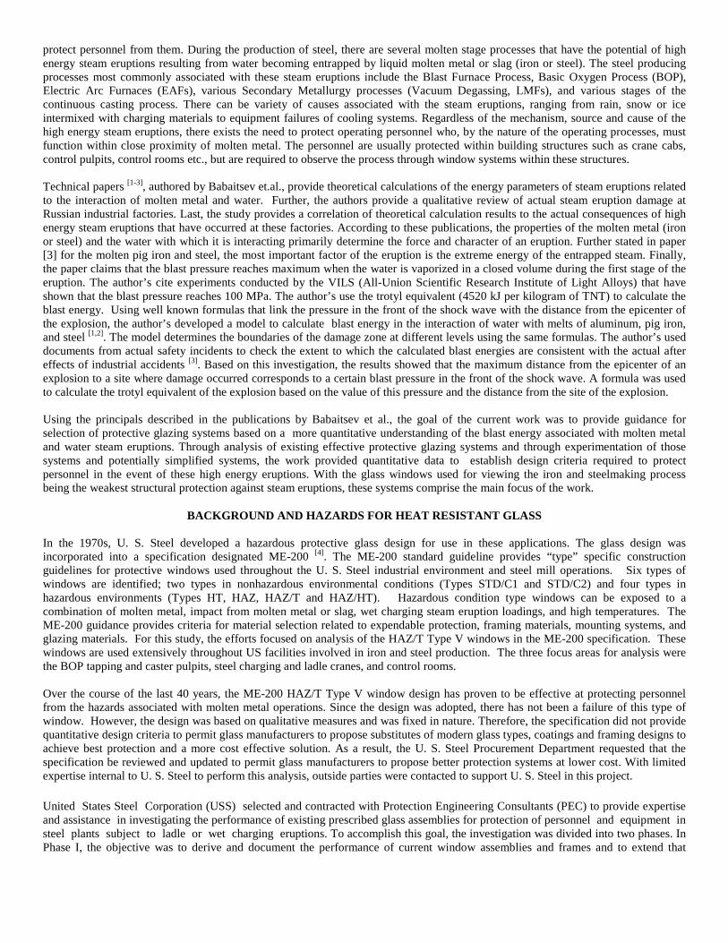
The HAZ/T Type V protective windows contain two or three main sections illustrated in Figure 1. Closest to the steel production is the expendable protective shield section or outer lite. This is typically two layers of laminated 1/8” soda lime float glass. Its purpose is to reduce damage to the more expensive window components from the frequent impact of slag and molten steel associated with the steel charging and processing events. This glass layer is replaced as needed during normal operations due to breakage or reduced visibility.
Figure 1. Illustration of construction of Type "V" Protective Window
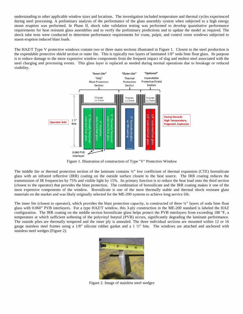
The middle lite or thermal protection section of the laminate contains ¼” low coefficient of thermal expansion (CTE) borosilicate glass with an infrared reflective (IRR) coating on the outside surface closest to the heat source. The IRR coating reduces the transmission of IR frequencies by 75% and visible light by 15%. Its primary function is to reduce the heat load onto the third section (closest to the operator) that provides the blast protection. The combination of borosilicate and the IRR coating makes it one of the most expensive components of the window. Borosilicate is one of the most thermally stable and thermal shock resistant glass materials on the market and was likely originally selected for the ME-200 systems to achieve long service life. The inner lite (closest to operator), which provides the blast protection capacity, is constructed of three ¼” layers of soda lime float glass with 0.060” PVB interlayers. For a type HAZ/T window, this 3-ply construction in the ME-200 standard is labeled the HAZ configuration. The IRR coating on the middle section borosilicate glass helps protect the PVB interlayers from exceeding 180 ºF, a temperature at which sufficient softening of the polyvinyl butyral (PVB) occurs, significantly degrading the laminate performance. The outside plies are thermally tempered and the inner ply is annealed. The three individual sections are mounted within 12 or 16 gauge stainless steel frames using a 1/8” silicone rubber gasket and a 1 ½” bite. The windows are attached and anchored with stainless steel wedges (Figure 2).
Figure 2. Image of stainless steel wedges
The investigation was initiated with the assumption that the current prescribed assemblies, as described in USS Standard Guideline ME-200, “Design Guidelines for Protective Window and Glazing Applications,” [4] provide necessary and adequate protection for normal plant operations. This assumption is based on the fact that the assembly in ME-200 has historically provided protection (and has in fact never been seen to fail) in actual wet charging eruptions in U. S. Steel plants. This HAZ baseline performance was then quantified through testing and analysis such that alternatives, possibly using alternative materials and glazing constructions, could be offered by vendors and procured by U. S. Steel.
As built drawings of various cranes, pulpits and control facilities were provided by USS to PEC for determination of typical sizes and configurations where the HAZ/T configuration is currently being used or will likely be retrofitted. In addition, USS provided input on the line of sight and standoff distance from the crane, pulpit, or control room window to the charging site (ladle). Drawings and information was provided for assemblies at the Edgar Thomson Works in Pennsylvania, the Fairfield Works in Alabama, the Gary Works in Indiana and the Canada Lake Erie Works. Table 1 below presents the data gathered from those drawings and the conclusions drawn regarding typical opening size. The data collected was used to determine “nominal” or typical sizes for use in establishing the performance of crane windows, pulpit windows and control room windows. Generally, sizes selected were biased towards the larger dimensions so as not to overestimate capacities in performance analysis. In general, crane and control room windows do not have a direct line of site to the ladle, thus slag impact is not common. However, it is common for slag and debris to impact pulpit windows (direct line of sight) in a shotgun pattern (multiple hits) with 0.25-in diameter debris.
Table 1. USS HAZ/T (ME-200 Illustration 5.5)) Applications and Typical Sizes for Capacity Calculations
PRELIMINARY ANALYSIS OF RESISTANCE TO BLAST FROM STEAM ERUPTIONS
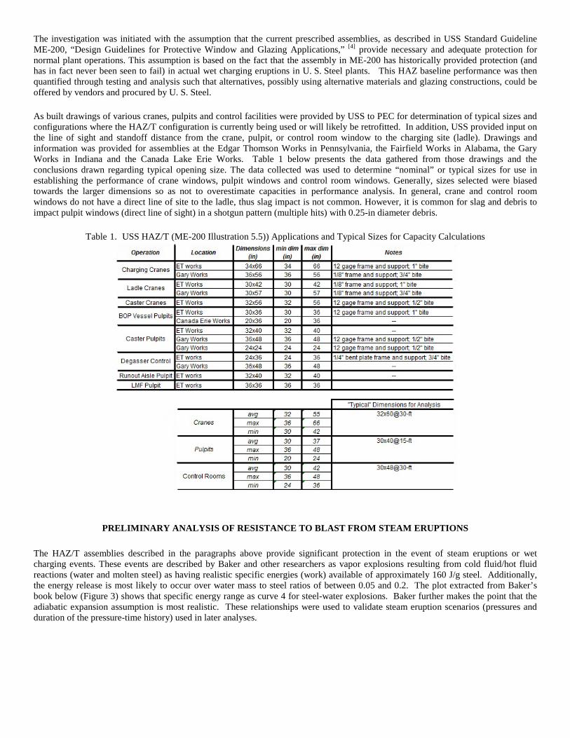
The HAZ/T assemblies described in the paragraphs above provide significant protection in the event of steam eruptions or wet charging events. These events are described by Baker and other researchers as vapor explosions resulting from cold fluid/hot fluid reactions (water and molten steel) as having realistic specific energies (work) available of approximately 160 J/g steel. Additionally, the energy release is most likely to occur over water mass to steel ratios of between 0.05 and 0.2. The plot extracted from Baker’s book below (Figure 3) shows that specific energy range as curve 4 for steel-water explosions. Baker further makes the point that the adiabatic expansion assumption is most realistic. These relationships were used to validate steam eruption scenarios (pressures and duration of the pressure-time history) used in later analyses.
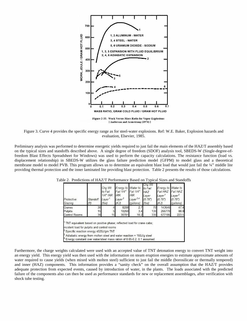
Figure 3. Curve 4 provides the specific energy range as for steel-water explosions. Ref: W.E. Baker, Explosion hazards and evaluation, Elsevier, 1985.
Preliminary analysis was performed to determine energetic yields required to just fail the main elements of the HAZ/T assembly based on the typical sizes and standoffs described above. A single degree of freedom (SDOF) analysis tool, SBEDS-W (Single-degree-of-freedom Blast Effects Spreadsheet for Windows) was used to perform the capacity calculations. The resistance function (load vs. displacement relationship) in SBEDS-W utilizes the glass failure prediction model (GFPM) to model glass and a theoretical membrane model to model PVB. This program allows us to determine an equivalent blast load that would just fail the ¼” middle lite providing thermal protection and the inner laminated lite providing blast protection. Table 2 presents the results of those calculations.
Table 2. Predictions of HAZ/T Performance Based on Typical Sizes and Standoffs
Furthermore, the charge weights calculated were used with an accepted value of TNT detonation energy to convert TNT weight into an energy yield. This energy yield was then used with the information on steam eruption energies to estimate approximate amounts of water required to cause yields (when mixed with molten steel) sufficient to just fail the middle (borosilicate or thermally tempered) and inner (HAZ) components. This information provides a “sanity check” on the overall assumption that the HAZ/T provides adequate protection from expected events, caused by introduction of water, in the plants. The loads associated with the predicted failure of the components also can then be used as performance standards for new or replacement assemblages, after verification with shock tube testing.
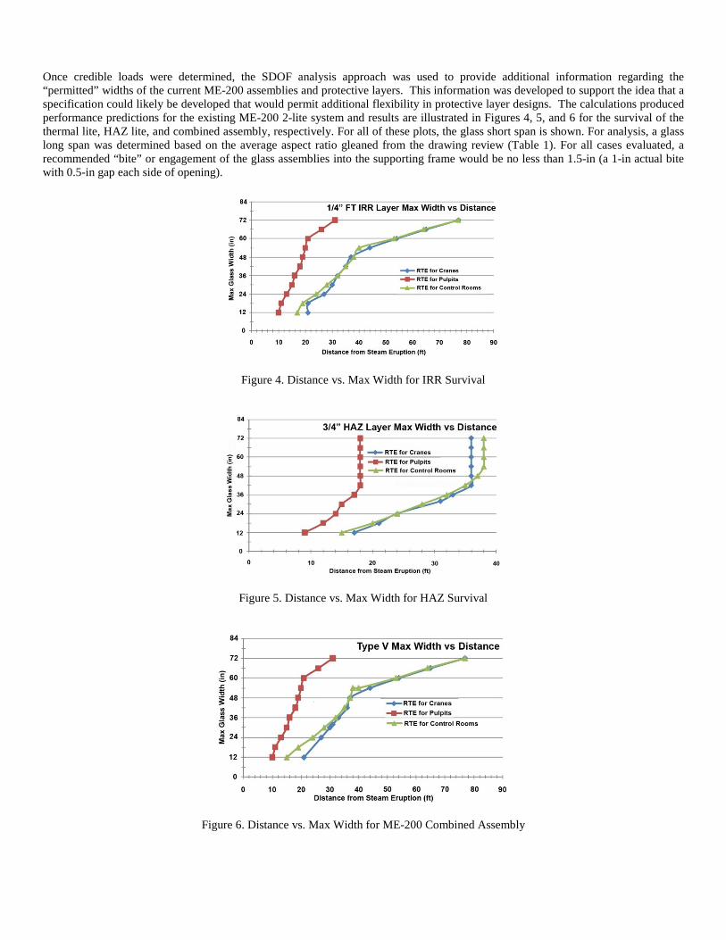
Once credible loads were determined, the SDOF analysis approach was used to provide additional information regarding the “permitted” widths of the current ME-200 assemblies and protective layers. This information was developed to support the idea that a specification could likely be developed that would permit additional flexibility in protective layer designs. The calculations produced performance predictions for the existing ME-200 2-lite system and results are illustrated in Figures 4, 5, and 6 for the survival of the thermal lite, HAZ lite, and combined assembly, respectively. For all of these plots, the glass short span is shown. For analysis, a glass long span was determined based on the average aspect ratio gleaned from the drawing review (Table 1). For all cases evaluated, a recommended “bite” or engagement of the glass assemblies into the supporting frame would be no less than 1.5-in (a 1-in actual bite with 0.5-in gap each side of opening).
Figure 4. Distance vs. Max Width for IRR Survival
Figure 5. Distance vs. Max Width for HAZ Survival
Figure 6. Distance vs. Max Width for ME-200 Combined Assembly
The analysis and investigations in Phase I of the effort demonstrated that protection from steam eruptions can be provided through both prescriptive and performance based approaches. The existing ME-200 specification is such a prescriptive requirement that is effective but limited in terms of size variation and lower cost alternatives. A better approach is derived from the analysis and testing conducted and described here where a performance requirement is established, allowing vendors and designers to offer site and size specific and lower cost alternatives. At the conclusion of Phase I of the subject effort, such a performance requirement, cast in terms of blast load pressure and duration, was envisioned. developed based on the preliminary analysis conducted as supported by historical performance of ME-200 assemblies and the enhanced understand of steam explosions derived from the literature. That preliminary performance based approach is illustrated in Table 3, and was the basis for the testing and additional analysis performed in Phase II of the effort.
THERMAL ANALYSIS
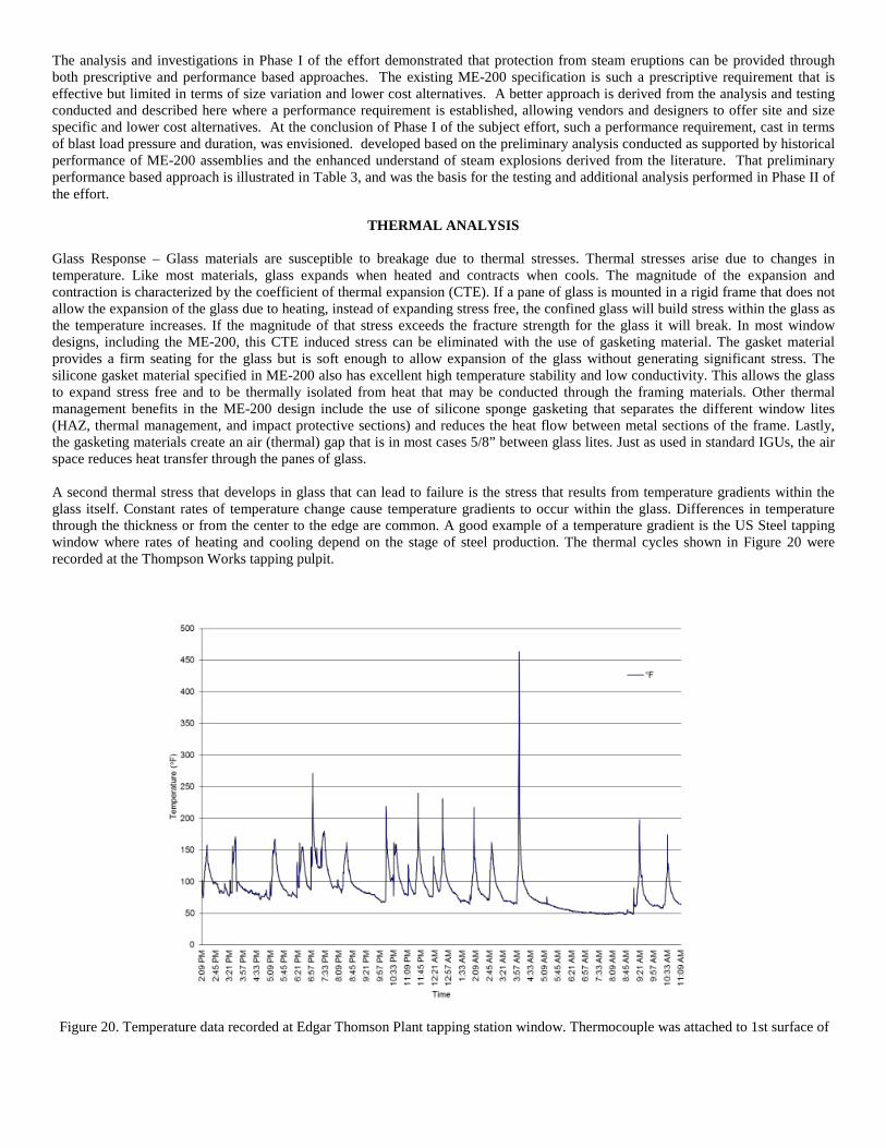
Glass Response – Glass materials are susceptible to breakage due to thermal stresses. Thermal stresses arise due to changes in temperature. Like most materials, glass expands when heated and contracts when cools. The magnitude of the expansion and contraction is characterized by the coefficient of thermal expansion (CTE). If a pane of glass is mounted in a rigid frame that does not allow the expansion of the glass due to heating, instead of expanding stress free, the confined glass will build stress within the glass as the temperature increases. If the magnitude of that stress exceeds the fracture strength for the glass it will break. In most window designs, including the ME-200, this CTE induced stress can be eliminated with the use of gasketing material. The gasket material provides a firm seating for the glass but is soft enough to allow expansion of the glass without generating significant stress. The silicone gasket material specified in ME-200 also has excellent high temperature stability and low conductivity. This allows the glass to expand stress free and to be thermally isolated from heat that may be conducted through the framing materials. Other thermal management benefits in the ME-200 design include the use of silicone sponge gasketing that separates the different window lites (HAZ, thermal management, and impact protective sections) and reduces the heat flow between metal sections of the frame. Lastly, the gasketing materials create an air (thermal) gap that is in most cases 5/8” between glass lites. Just as used in standard IGUs, the air space reduces heat transfer through the panes of glass. A second thermal stress that develops in glass that can lead to failure is the stress that results from temperature gradients within the glass itself. Constant rates of temperature change cause temperature gradients to occur within the glass. Differences in temperature through the thickness or from the center to the edge are common. A good example of a temperature gradient is the US Steel tapping window where rates of heating and cooling depend on the stage of steel production. The thermal cycles shown in Figure 20 were recorded at the Thompson Works tapping pulpit.
Figure 20. Temperature data recorded at Edgar Thomson Plant tapping station window. Thermocouple was attached to 1st surface of
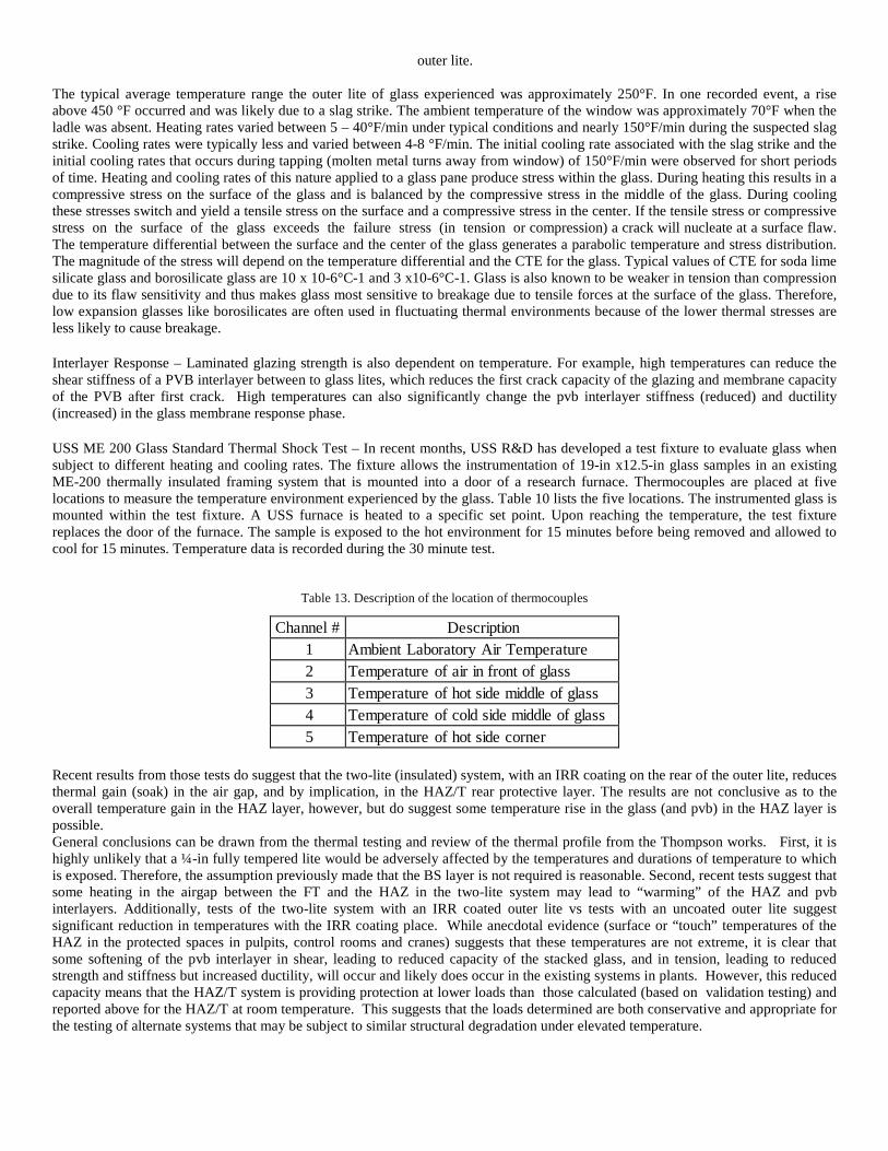
outer lite. The typical average temperature range the outer lite of glass experienced was approximately 250°F. In one recorded event, a rise above 450 °F occurred and was likely due to a slag strike. The ambient temperature of the window was approximately 70°F when the ladle was absent. Heating rates varied between 5 – 40°F/min under typical conditions and nearly 150°F/min during the suspected slag strike. Cooling rates were typically less and varied between 4-8 °F/min. The initial cooling rate associated with the slag strike and the initial cooling rates that occurs during tapping (molten metal turns away from window) of 150°F/min were observed for short periods of time. Heating and cooling rates of this nature applied to a glass pane produce stress within the glass. During heating this results in a compressive stress on the surface of the glass and is balanced by the compressive stress in the middle of the glass. During cooling these stresses switch and yield a tensile stress on the surface and a compressive stress in the center. If the tensile stress or compressive stress on the surface of the glass exceeds the failure stress (in tension or compression) a crack will nucleate at a surface flaw. The temperature differential between the surface and the center of the glass generates a parabolic temperature and stress distribution. The magnitude of the stress will depend on the temperature differential and the CTE for the glass. Typical values of CTE for soda lime silicate glass and borosilicate glass are 10 x 10-6°C-1 and 3 x10⁻⁶°C-1. Glass is also known to be weaker in tension than compression due to its flaw sensitivity and thus makes glass most sensitive to breakage due to tensile forces at the surface of the glass. Therefore, low expansion glasses like borosilicates are often used in fluctuating thermal environments because of the lower thermal stresses are less likely to cause breakage. Interlayer Response – Laminated glazing strength is also dependent on temperature. For example, high temperatures can reduce the shear stiffness of a PVB interlayer between to glass lites, which reduces the first crack capacity of the glazing and membrane capacity of the PVB after first crack. High temperatures can also significantly change the pvb interlayer stiffness (reduced) and ductility (increased) in the glass membrane response phase. USS ME 200 Glass Standard Thermal Shock Test – In recent months, USS R&D has developed a test fixture to evaluate glass when subject to different heating and cooling rates. The fixture allows the instrumentation of 19-in x12.5-in glass samples in an existing ME-200 thermally insulated framing system that is mounted into a door of a research furnace. Thermocouples are placed at five locations to measure the temperature environment experienced by the glass. Table 10 lists the five locations. The instrumented glass is mounted within the test fixture. A USS furnace is heated to a specific set point. Upon reaching the temperature, the test fixture replaces the door of the furnace. The sample is exposed to the hot environment for 15 minutes before being removed and allowed to cool for 15 minutes. Temperature data is recorded during the 30 minute test.
Table 13. Description of the location of thermocouples
Channel # Description 1 Ambient Laboratory Air Temperature 2 Temperature of air in front of glass 3 Temperature of hot side middle of glass 4 Temperature of cold side middle of glass 5 Temperature of hot side corner
Recent results from those tests do suggest that the two-lite (insulated) system, with an IRR coating on the rear of the outer lite, reduces thermal gain (soak) in the air gap, and by implication, in the HAZ/T rear protective layer. The results are not conclusive as to the overall temperature gain in the HAZ layer, however, but do suggest some temperature rise in the glass (and pvb) in the HAZ layer is possible. General conclusions can be drawn from the thermal testing and review of the thermal profile from the Thompson works. First, it is highly unlikely that a ¼-in fully tempered lite would be adversely affected by the temperatures and durations of temperature to which is exposed. Therefore, the assumption previously made that the BS layer is not required is reasonable. Second, recent tests suggest that some heating in the airgap between the FT and the HAZ in the two-lite system may lead to “warming” of the HAZ and pvb interlayers. Additionally, tests of the two-lite system with an IRR coated outer lite vs tests with an uncoated outer lite suggest significant reduction in temperatures with the IRR coating place. While anecdotal evidence (surface or “touch” temperatures of the HAZ in the protected spaces in pulpits, control rooms and cranes) suggests that these temperatures are not extreme, it is clear that some softening of the pvb interlayer in shear, leading to reduced capacity of the stacked glass, and in tension, leading to reduced strength and stiffness but increased ductility, will occur and likely does occur in the existing systems in plants. However, this reduced capacity means that the HAZ/T system is providing protection at lower loads than those calculated (based on validation testing) and reported above for the HAZ/T at room temperature. This suggests that the loads determined are both conservative and appropriate for the testing of alternate systems that may be subject to similar structural degradation under elevated temperature.
Thus, no structural test under elevated temperatures is necessary or recommended for HAZ/T alternates. It is recommended that any alternative systems be subjected to the thermal loads and cycles like those determined from the Thompson Works such that cracking or catastrophic material response (surface melt, delamination or overall material softening), if likely in the alternate, can be observed.
TEST MATRIX FOR SHOCK TUBE TESTING
In Phase II of the effort, shock tube tests were planned and conducted to quantify the performance of the HAZ/T. Since configurations used in plants had historically evolved from the specified two-lite (Borosilicate-air gap-HAZ/T to three-lite (sacrificial annealed/fully tempered/wired glass/etc-air gap-Borosilicate- air gap-HAZ/T) configurations, both three-lite and two-lite systems were evaluated. Additionally, since the cost of the Borosilicate glass is high, and since the efficacy of that glass is questionable, two-lite configurations with fully tempered glass substituted for the Borosilicate were tested.
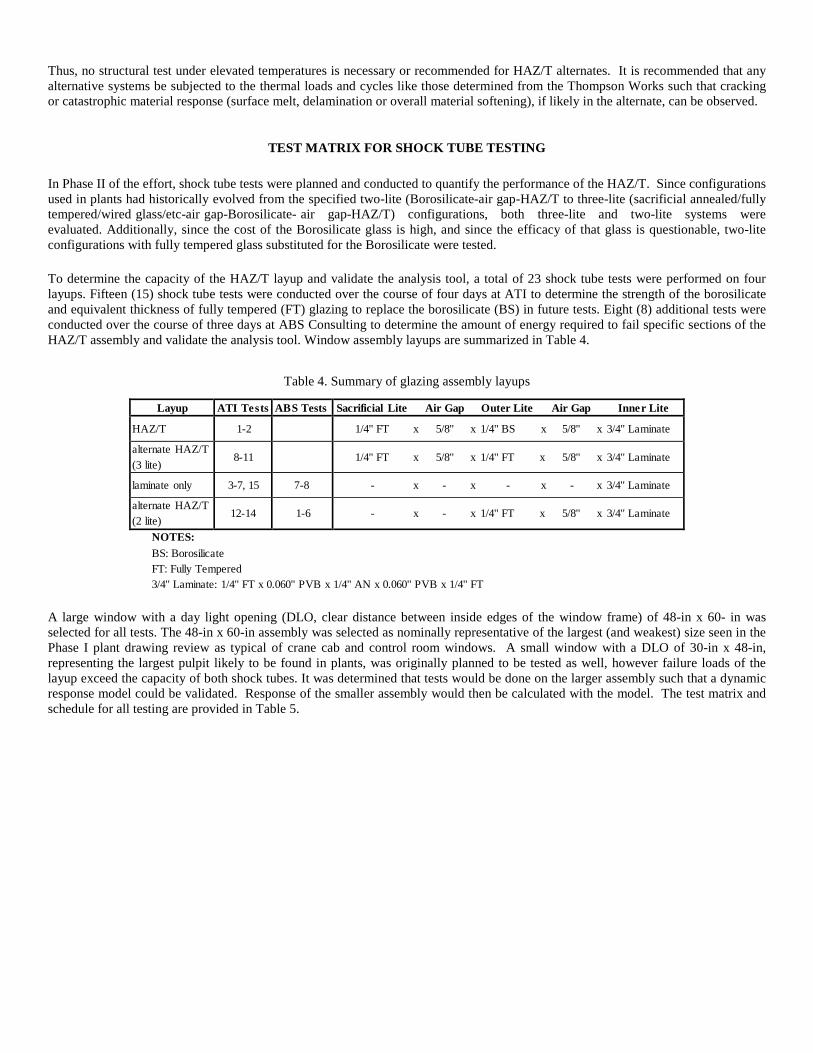
To determine the capacity of the HAZ/T layup and validate the analysis tool, a total of 23 shock tube tests were performed on four layups. Fifteen (15) shock tube tests were conducted over the course of four days at ATI to determine the strength of the borosilicate and equivalent thickness of fully tempered (FT) glazing to replace the borosilicate (BS) in future tests. Eight (8) additional tests were conducted over the course of three days at ABS Consulting to determine the amount of energy required to fail specific sections of the HAZ/T assembly and validate the analysis tool. Window assembly layups are summarized in Table 4.
Table 4. Summary of glazing assembly layups
Layup ATI Te s ts AB S Tests Sacrificial Lite Air Gap Outer Lite Air Gap Inne r Lite
HAZ/T 1-2 1/4" FT x 5/8" x 1/4" BS x 5/8" x 3/4" Laminate alternate HAZ/T (3 lite)
8-11
1/4" FT x 5/8" x 1/4" FT x 5/8" x 3/4" Laminate
laminate only 3-7, 15 7-8 - x - x - x - x 3/4" Laminate alternate HAZ/T (2 lite)
12-14
1-6
- x - x 1/4" FT x 5/8" x 3/4" Laminate
NOTES: BS: Borosilicate FT: Fully Tempered 3/4" Laminate: 1/4" FT x 0.060" PVB x 1/4" AN x 0.060" PVB x 1/4" FT
A large window with a day light opening (DLO, clear distance between inside edges of the window frame) of 48-in x 60- in was selected for all tests. The 48-in x 60-in assembly was selected as nominally representative of the largest (and weakest) size seen in the Phase I plant drawing review as typical of crane cab and control room windows. A small window with a DLO of 30-in x 48-in, representing the largest pulpit likely to be found in plants, was originally planned to be tested as well, however failure loads of the layup exceed the capacity of both shock tubes. It was determined that tests would be done on the larger assembly such that a dynamic response model could be validated. Response of the smaller assembly would then be calculated with the model. The test matrix and schedule for all testing are provided in Table 5.
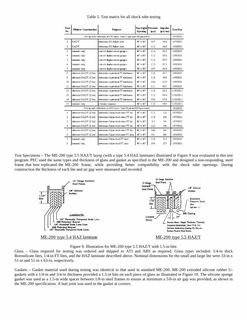
Table 5. Test matrix for all shock tube testing
Test Specimens – The ME-200 type 5.5 HAZ/T layup (with a type 5.4 HAZ laminate) illustrated in Figure 9 was evaluated in this test program. PEC used the same types and thickness of glass and gasket as specified in the ME-200 and designed a non-responding, steel frame that best replicated the ME-200 frame, while providing better compatibility with the shock tube openings. During construction the thickness of each lite and air gap were measured and recorded.
ME-200 type 5.4 HAZ laminate ME-200 type 5.5 HAZ/T
Figure 9. Illustration for ME-200 type 5.5 HAZ/T with 1.5-in bite. Glass – Glass required for testing was ordered and shipped to ATI and ABS as required. Glass types included: 1/4-in thick Borosilicate lites, 1/4-in FT lites, and the HAZ laminate described above. Nominal dimensions for the small and large lite were 33-in x 51-in and 51-in x 63-in, respectively. Gaskets – Gasket material used during testing was identical to that used in standard ME-200. ME-200 extruded silicone rubber U-gaskets with a 1/4-in and 3/4-in thickness provided a 1.5-in bite on each piece of glass as illustrated in Figure 10. The silicone sponge gasket was used as a 1.5-in wide spacer between 1/8-in steel frames to ensure at minimum a 5/8-in air gap was provided, as shown in the ME-200 specification. A butt joint was used in the gasket at corners.
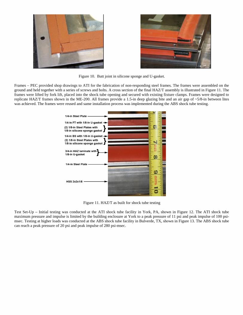
Figure 10. Butt joint in silicone sponge and U-gasket. Frames – PEC provided shop drawings to ATI for the fabrication of non-responding steel frames. The frames were assembled on the ground and held together with a series of screws and bolts. A cross section of the final HAZ/T assembly is illustrated in Figure 11. The frames were lifted by fork lift, placed into the shock tube opening and secured with existing fixture clamps. Frames were designed to replicate HAZ/T frames shown in the ME-200. All frames provide a 1.5-in deep glazing bite and an air gap of ~5/8-in between lites was achieved. The frames were reused and same installation process was implemented during the ABS shock tube testing.
Figure 11. HAZ/T as built for shock tube testing Test Set-Up – Initial testing was conducted at the ATI shock tube facility in York, PA, shown in Figure 12. The ATI shock tube maximum pressure and impulse is limited by the building enclosure at York to a peak pressure of 11 psi and peak impulse of 100 psi-msec. Testing at higher loads was conducted at the ABS shock tube facility in Bulverde, TX, shown in Figure 13. The ABS shock tube can reach a peak pressure of 20 psi and peak impulse of 280 psi-msec.
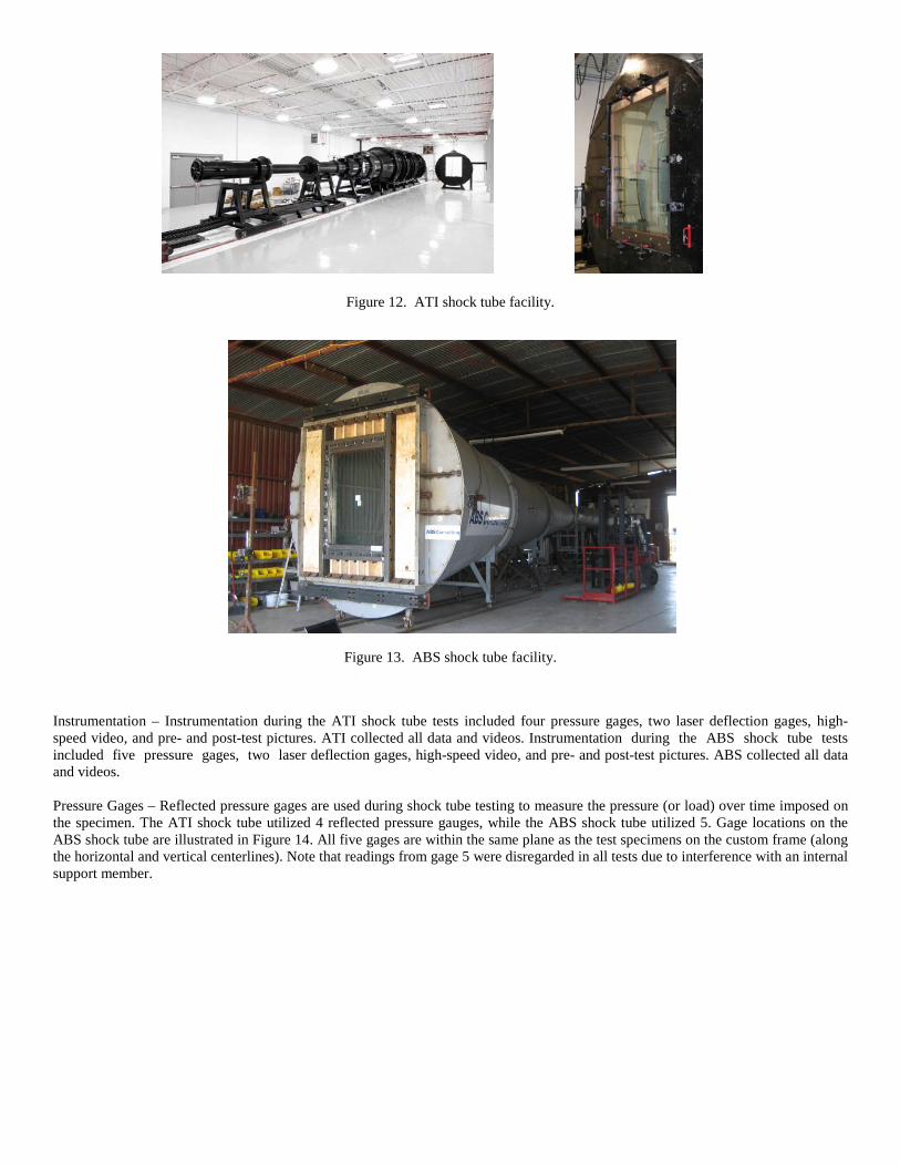
Figure 12. ATI shock tube facility.
Figure 13. ABS shock tube facility. Instrumentation – Instrumentation during the ATI shock tube tests included four pressure gages, two laser deflection gages, high-speed video, and pre- and post-test pictures. ATI collected all data and videos. Instrumentation during the ABS shock tube tests included five pressure gages, two laser deflection gages, high-speed video, and pre- and post-test pictures. ABS collected all data and videos. Pressure Gages – Reflected pressure gages are used during shock tube testing to measure the pressure (or load) over time imposed on the specimen. The ATI shock tube utilized 4 reflected pressure gauges, while the ABS shock tube utilized 5. Gage locations on the ABS shock tube are illustrated in Figure 14. All five gages are within the same plane as the test specimens on the custom frame (along the horizontal and vertical centerlines). Note that readings from gage 5 were disregarded in all tests due to interference with an internal support member.
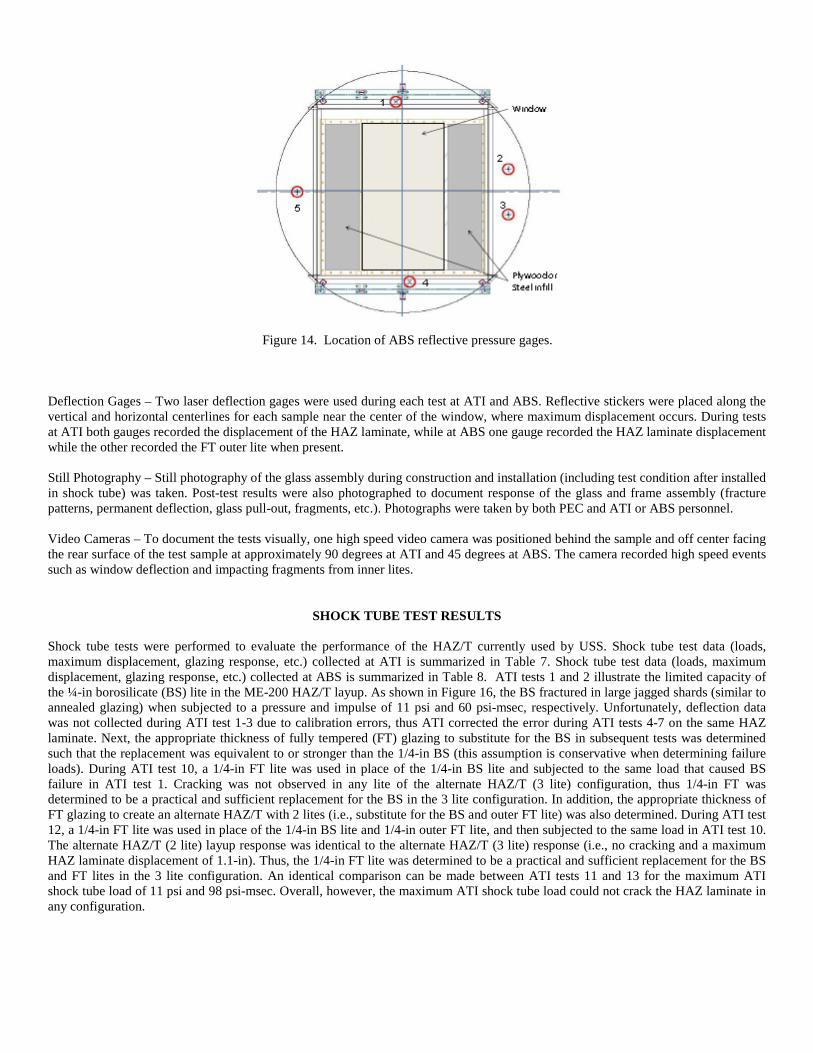
Figure 14. Location of ABS reflective pressure gages.
Deflection Gages – Two laser deflection gages were used during each test at ATI and ABS. Reflective stickers were placed along the vertical and horizontal centerlines for each sample near the center of the window, where maximum displacement occurs. During tests at ATI both gauges recorded the displacement of the HAZ laminate, while at ABS one gauge recorded the HAZ laminate displacement while the other recorded the FT outer lite when present. Still Photography – Still photography of the glass assembly during construction and installation (including test condition after installed in shock tube) was taken. Post-test results were also photographed to document response of the glass and frame assembly (fracture patterns, permanent deflection, glass pull-out, fragments, etc.). Photographs were taken by both PEC and ATI or ABS personnel. Video Cameras – To document the tests visually, one high speed video camera was positioned behind the sample and off center facing the rear surface of the test sample at approximately 90 degrees at ATI and 45 degrees at ABS. The camera recorded high speed events such as window deflection and impacting fragments from inner lites.
SHOCK TUBE TEST RESULTS
Shock tube tests were performed to evaluate the performance of the HAZ/T currently used by USS. Shock tube test data (loads, maximum displacement, glazing response, etc.) collected at ATI is summarized in Table 7. Shock tube test data (loads, maximum displacement, glazing response, etc.) collected at ABS is summarized in Table 8. ATI tests 1 and 2 illustrate the limited capacity of the ¼-in borosilicate (BS) lite in the ME-200 HAZ/T layup. As shown in Figure 16, the BS fractured in large jagged shards (similar to annealed glazing) when subjected to a pressure and impulse of 11 psi and 60 psi-msec, respectively. Unfortunately, deflection data was not collected during ATI test 1-3 due to calibration errors, thus ATI corrected the error during ATI tests 4-7 on the same HAZ laminate. Next, the appropriate thickness of fully tempered (FT) glazing to substitute for the BS in subsequent tests was determined such that the replacement was equivalent to or stronger than the 1/4-in BS (this assumption is conservative when determining failure loads). During ATI test 10, a 1/4-in FT lite was used in place of the 1/4-in BS lite and subjected to the same load that caused BS failure in ATI test 1. Cracking was not observed in any lite of the alternate HAZ/T (3 lite) configuration, thus 1/4-in FT was determined to be a practical and sufficient replacement for the BS in the 3 lite configuration. In addition, the appropriate thickness of FT glazing to create an alternate HAZ/T with 2 lites (i.e., substitute for the BS and outer FT lite) was also determined. During ATI test 12, a 1/4-in FT lite was used in place of the 1/4-in BS lite and 1/4-in outer FT lite, and then subjected to the same load in ATI test 10. The alternate HAZ/T (2 lite) layup response was identical to the alternate HAZ/T (3 lite) response (i.e., no cracking and a maximum HAZ laminate displacement of 1.1-in). Thus, the 1/4-in FT lite was determined to be a practical and sufficient replacement for the BS and FT lites in the 3 lite configuration. An identical comparison can be made between ATI tests 11 and 13 for the maximum ATI shock tube load of 11 psi and 98 psi-msec. Overall, however, the maximum ATI shock tube load could not crack the HAZ laminate in any configuration.
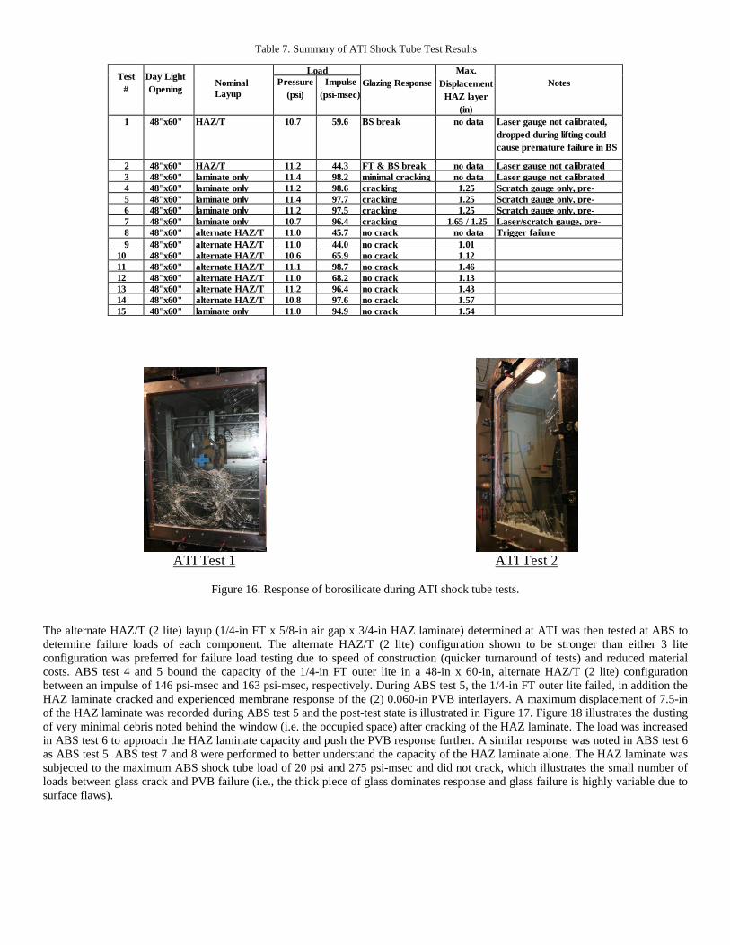
Table 7. Summary of ATI Shock Tube Test Results
Test #
Day Light Opening
Nominal Layup
Load Glazing Response
Max. Displacement
HAZ layer (in)
Notes Pressure
(psi) Impulse
(psi-msec)
1 48"x60" HAZ/T 10.7 59.6 BS break no data Laser gauge not calibrated, dropped during lifting could cause premature failure in BS
2 48"x60" HAZ/T 11.2 44.3 FT & BS break no data Laser gauge not calibrated 3 48"x60" laminate only 11.4 98.2 minimal cracking no data Laser gauge not calibrated 4 48"x60" laminate only 11.2 98.6 cracking 1.25 Scratch gauge only, pre-
5 48"x60" laminate only 11.4 97.7 cracking 1.25 Scratch gauge only, pre- 6 48"x60" laminate only 11.2 97.5 cracking 1.25 Scratch gauge only, pre- 7 48"x60" laminate only 10.7 96.4 cracking 1.65 / 1.25 Laser/scratch gauge, pre- 8 48"x60" alternate HAZ/T
11.0 45.7 no crack no data Trigger failure
9 48"x60" alternate HAZ/T
11.0 44.0 no crack 1.01 10 48"x60" alternate HAZ/T
10.6 65.9 no crack 1.12
11 48"x60" alternate HAZ/T
11.1 98.7 no crack 1.46 12 48"x60" alternate HAZ/T
11.0 68.2 no crack 1.13
13 48"x60" alternate HAZ/T
11.2 96.4 no crack 1.43 14 48"x60" alternate HAZ/T
10.8 97.6 no crack 1.57
15 48"x60" laminate only 11.0 94.9 no crack 1.54
ATI Test 1 ATI Test 2
Figure 16. Response of borosilicate during ATI shock tube tests.
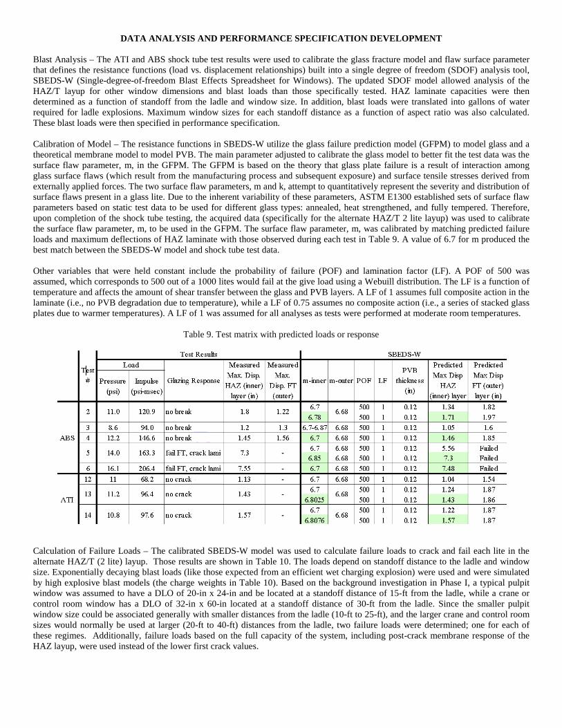
The alternate HAZ/T (2 lite) layup (1/4-in FT x 5/8-in air gap x 3/4-in HAZ laminate) determined at ATI was then tested at ABS to determine failure loads of each component. The alternate HAZ/T (2 lite) configuration shown to be stronger than either 3 lite configuration was preferred for failure load testing due to speed of construction (quicker turnaround of tests) and reduced material costs. ABS test 4 and 5 bound the capacity of the 1/4-in FT outer lite in a 48-in x 60-in, alternate HAZ/T (2 lite) configuration between an impulse of 146 psi-msec and 163 psi-msec, respectively. During ABS test 5, the 1/4-in FT outer lite failed, in addition the HAZ laminate cracked and experienced membrane response of the (2) 0.060-in PVB interlayers. A maximum displacement of 7.5-in of the HAZ laminate was recorded during ABS test 5 and the post-test state is illustrated in Figure 17. Figure 18 illustrates the dusting of very minimal debris noted behind the window (i.e. the occupied space) after cracking of the HAZ laminate. The load was increased in ABS test 6 to approach the HAZ laminate capacity and push the PVB response further. A similar response was noted in ABS test 6 as ABS test 5. ABS test 7 and 8 were performed to better understand the capacity of the HAZ laminate alone. The HAZ laminate was subjected to the maximum ABS shock tube load of 20 psi and 275 psi-msec and did not crack, which illustrates the small number of loads between glass crack and PVB failure (i.e., the thick piece of glass dominates response and glass failure is highly variable due to surface flaws).
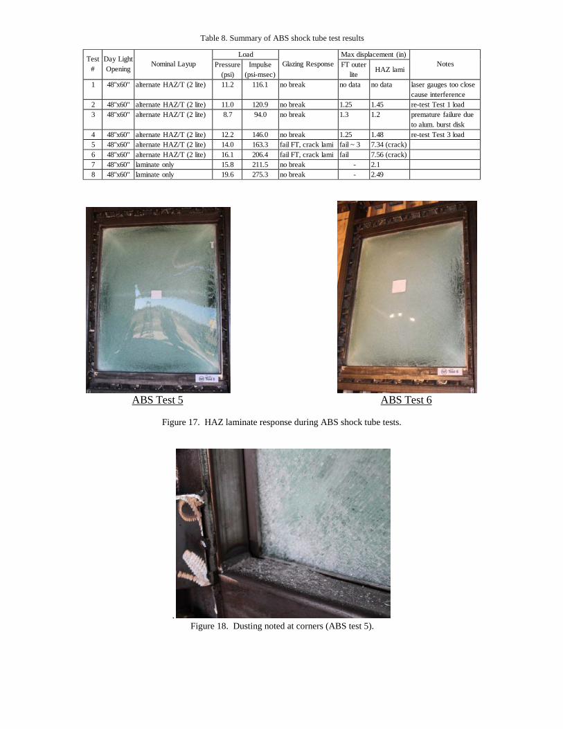
Table 8. Summary of ABS shock tube test results
Test
# Day Light Opening
Nominal Layup
Load Glazing Response
Max displacement (in) Notes Pressure
(psi) Impulse
(psi-msec) FT outer
lite
HAZ lami 1 48"x60" alternate HAZ/T (2 lite) 11.2 116.1 no break no data no data laser gauges too close
cause interference 2 48"x60" alternate HAZ/T (2 lite) 11.0 120.9 no break 1.25 1.45 re-test Test 1 load 3 48"x60" alternate HAZ/T (2 lite) 8.7 94.0 no break 1.3 1.2 premature failure due
to alum. burst disk 4 48"x60" alternate HAZ/T (2 lite) 12.2 146.0 no break 1.25 1.48 re-test Test 3 load 5 48"x60" alternate HAZ/T (2 lite) 14.0 163.3 fail FT, crack lami fail ~ 3 7.34 (crack) 6 48"x60" alternate HAZ/T (2 lite) 16.1 206.4 fail FT, crack lami fail 7.56 (crack) 7 48"x60" laminate only 15.8 211.5 no break - 2.1 8 48"x60" laminate only 19.6 275.3 no break - 2.49
ABS Test 5 ABS Test 6
Figure 17. HAZ laminate response during ABS shock tube tests.
. Figure 18. Dusting noted at corners (ABS test 5).
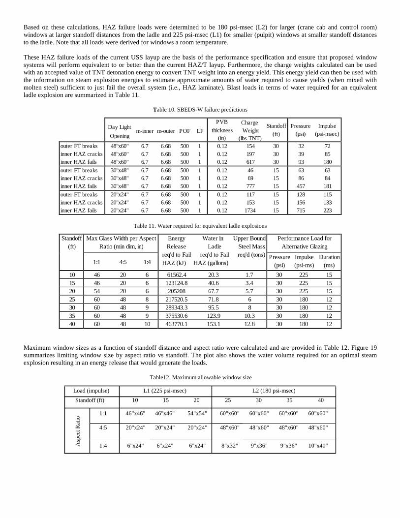
DATA ANALYSIS AND PERFORMANCE SPECIFICATION DEVELOPMENT Blast Analysis – The ATI and ABS shock tube test results were used to calibrate the glass fracture model and flaw surface parameter that defines the resistance functions (load vs. displacement relationships) built into a single degree of freedom (SDOF) analysis tool, SBEDS-W (Single-degree-of-freedom Blast Effects Spreadsheet for Windows). The updated SDOF model allowed analysis of the HAZ/T layup for other window dimensions and blast loads than those specifically tested. HAZ laminate capacities were then determined as a function of standoff from the ladle and window size. In addition, blast loads were translated into gallons of water required for ladle explosions. Maximum window sizes for each standoff distance as a function of aspect ratio was also calculated. These blast loads were then specified in performance specification. Calibration of Model – The resistance functions in SBEDS-W utilize the glass failure prediction model (GFPM) to model glass and a theoretical membrane model to model PVB. The main parameter adjusted to calibrate the glass model to better fit the test data was the surface flaw parameter, m, in the GFPM. The GFPM is based on the theory that glass plate failure is a result of interaction among glass surface flaws (which result from the manufacturing process and subsequent exposure) and surface tensile stresses derived from externally applied forces. The two surface flaw parameters, m and k, attempt to quantitatively represent the severity and distribution of surface flaws present in a glass lite. Due to the inherent variability of these parameters, ASTM E1300 established sets of surface flaw parameters based on static test data to be used for different glass types: annealed, heat strengthened, and fully tempered. Therefore, upon completion of the shock tube testing, the acquired data (specifically for the alternate HAZ/T 2 lite layup) was used to calibrate the surface flaw parameter, m, to be used in the GFPM. The surface flaw parameter, m, was calibrated by matching predicted failure loads and maximum deflections of HAZ laminate with those observed during each test in Table 9. A value of 6.7 for m produced the best match between the SBEDS-W model and shock tube test data. Other variables that were held constant include the probability of failure (POF) and lamination factor (LF). A POF of 500 was assumed, which corresponds to 500 out of a 1000 lites would fail at the give load using a Webuill distribution. The LF is a function of temperature and affects the amount of shear transfer between the glass and PVB layers. A LF of 1 assumes full composite action in the laminate (i.e., no PVB degradation due to temperature), while a LF of 0.75 assumes no composite action (i.e., a series of stacked glass plates due to warmer temperatures). A LF of 1 was assumed for all analyses as tests were performed at moderate room temperatures.
Table 9. Test matrix with predicted loads or response
Calculation of Failure Loads – The calibrated SBEDS-W model was used to calculate failure loads to crack and fail each lite in the alternate HAZ/T (2 lite) layup. Those results are shown in Table 10. The loads depend on standoff distance to the ladle and window size. Exponentially decaying blast loads (like those expected from an efficient wet charging explosion) were used and were simulated by high explosive blast models (the charge weights in Table 10). Based on the background investigation in Phase I, a typical pulpit window was assumed to have a DLO of 20-in x 24-in and be located at a standoff distance of 15-ft from the ladle, while a crane or control room window has a DLO of 32-in x 60-in located at a standoff distance of 30-ft from the ladle. Since the smaller pulpit window size could be associated generally with smaller distances from the ladle (10-ft to 25-ft), and the larger crane and control room sizes would normally be used at larger (20-ft to 40-ft) distances from the ladle, two failure loads were determined; one for each of these regimes. Additionally, failure loads based on the full capacity of the system, including post-crack membrane response of the HAZ layup, were used instead of the lower first crack values.
Asp
ect R
atio
Based on these calculations, HAZ failure loads were determined to be 180 psi-msec (L2) for larger (crane cab and control room) windows at larger standoff distances from the ladle and 225 psi-msec (L1) for smaller (pulpit) windows at smaller standoff distances to the ladle. Note that all loads were derived for windows a room temperature. These HAZ failure loads of the current USS layup are the basis of the performance specification and ensure that proposed window systems will perform equivalent to or better than the current HAZ/T layup. Furthermore, the charge weights calculated can be used with an accepted value of TNT detonation energy to convert TNT weight into an energy yield. This energy yield can then be used with the information on steam explosion energies to estimate approximate amounts of water required to cause yields (when mixed with molten steel) sufficient to just fail the overall system (i.e., HAZ laminate). Blast loads in terms of water required for an equivalent ladle explosion are summarized in Table 11.
Table 10. SBEDS-W failure predictions
Day Light
m-inner m-outer POF LF Opening
PVB Charge thickness Weight
Standoff (in) (lbs TNT)
(ft)
Pressure Impulse
(psi) (psi-msec) outer FT breaks inner HAZ cracks inner HAZ fails
48"x60" 6.7 6.68 500 1 48"x60" 6.7 6.68 500 1 48"x60" 6.7 6.68 500 1
0.12 154 30 0.12 197 30 0.12 617 30
32 72 39 85 93 180
outer FT breaks inner HAZ cracks inner HAZ fails
30"x48" 6.7 6.68 500 1 30"x48" 6.7 6.68 500 1 30"x48" 6.7 6.68 500 1
0.12 46 15 0.12 69 15 0.12 777 15
63 63 86 84
457 181 outer FT breaks inner HAZ cracks inner HAZ fails
20"x24" 6.7 6.68 500 1 20"x24" 6.7 6.68 500 1 20"x24" 6.7 6.68 500 1
0.12 117 15 0.12 153 15 0.12 1734 15
128 115 156 133 715 223
Table 11. Water required for equivalent ladle explosions
Standoff (ft)
Max Glass Width per Aspect Ratio (min dim, in)
Energy Water in Upper Bound Release Ladle Steel Mass
req'd to Fail req'd to Fail req'd (tons) HAZ (kJ) HAZ (gallons)
Performance Load for Alternative Glazing
1:1 4:5 1:4 Pressure Impulse Duration
(psi) (psi-ms) (ms) 10 46 20 6 61562.4 20.3 1.7 30 225 15 15 46 20 6 123124.8 40.6 3.4 30 225 15 20 54 20 6 205208 67.7 5.7 30 225 15 25 60 48 8 217520.5 71.8 6 30 180 12 30 60 48 9 289343.3 95.5 8 30 180 12 35 60 48 9 375530.6 123.9 10.3 30 180 12 40 60 48 10 463770.1 153.1 12.8 30 180 12
Maximum window sizes as a function of standoff distance and aspect ratio were calculated and are provided in Table 12. Figure 19 summarizes limiting window size by aspect ratio vs standoff. The plot also shows the water volume required for an optimal steam explosion resulting in an energy release that would generate the loads.
Table12. Maximum allowable window size Load (impulse) L1 (225 psi-msec) L2 (180 psi-msec)
Standoff (ft) 10 15 20 25 30 35 40 1:1 46"x46" 46"x46" 54"x54" 60"x60" 60"x60" 60"x60" 60"x60" 4:5 20"x24" 20"x24" 20"x24" 48"x60" 48"x60" 48"x60" 48"x60"
1:4 6"x24" 6"x24" 6"x24" 8"x32" 9"x36" 9"x36" 10"x40"
Figure 19. Maximum window width and water required for equivalent ladle explosion.
CONCLUSIONS
United States Steel and Protection Engineering Consultants (PEC) have provided performance requirements for glass assemblies used in crane, control room or pulpit applications at steel plants that protect personnel and equipment from steam eruptions. The HAZ/T assembly in ME-200 was tested and results were analyzed to determine basic structural capacity under blast load. A calibrated window model based on the shock tube test data allowed performance requirements to be extrapolated to different window sizes and loads. Thus, future alternative systems provided by U. S. Steel vendors will be able to validate designs with shock tube testing. Basic thermal observations from temperature data provided by U. S. Steel are also provided. Blast and thermal load requirements based on the test results and subsequent analysis are summarized for use in the updated U. S. Steel window specification.
ACKNOWLEDGMENT
The authors wish to acknowledge the following individuals for their contributions to this paper. First, thanks to Mary Sherwin from United States Steel Procurement Division for initiating the work. Also, thanks to Teresa M. Speiran and James B. Neubauer from United States Steel Research for developing the testing apparatus and lab procedures for thermal testing. Next, thanks to the operating personnel at United States Steel Edgar Thomson BOP Shop, particularly Don Stanich, for supporting the in plant thermal measurements. Finally, thanks to Samuel Smith, Dr. Tom Piccone, Dr. Yun Li and Dr. Robert Hyland from United States Steel Research for their critical review of the paper. Additional thanks goes to Jerry Collinsworth at ABS Consulting for their assistance in performing the shock tube testing in Bulverde, Texas.
REFERENCES
I. V. Babaitsev and N. A. Dzhemilev, "Evaluating the after-effects of explosions occurring in the accidental interaction of molten metals with water;' Bezop. Tr. Promst., No.9, 24 (1994).
I. V. Babaitsev, E. V. Popova, N. A. Dzhemilev, et al., "'Procedural recommendations on evaluating the after-effects of explosions accompanying the accidental release of molten metal;' ibid., No.6, 36 (1995)
I. V. Babaitsev and O. V. Kuznetsov, “Energy of Explosions Ocurring When Water Falls Onto a Layer of Molten Metal,” Moscow State Institute of Steel and Alloys (Technological University). Translated from Metallurg, No.5, pp. 29-30, May, 2001.
USS Standard Guideline ME-200, “Design Guidelines for Protective Window and Glazing Applications,” Internal U. S. Steel Document
ASTM Standard E1300, “Standard Practice for Determining Load Resistance of Glass in Buildings”, ASTM International, West Conshohocken, PA, 2012, DOI: 10.1520/F2248-09, www.astm.org.
Beason, W. Lynn and Morgan, James R., “Glass Failure Prediction Model”, Journal of Structural Engineering, Vol. 110, No. 2, ASCE, February 1984.

US Army Corps of Engineers Protective Design Center (USACE PDC), “HazL v1.2”, July 2004. US Army Corps of Engineers Protective Design Center (USACE PDC), “Single-degree-of-freedom Blast Effects Spreadsheet for
Windows Version 1.0” (SBEDS-W v1.0), 2014.
DISCLAIMER
The material in this paper is intended for general information only. Any use of this material in relation to any specific application should be based on independent examination and verification of its unrestricted availability for such use and a determination of suitability for the application by professionally qualified personnel. No license under any patents or other proprietary interests are implied by the publication of this paper. Those making use of or relying upon the material assume all risks and liability arising from such use or reliance.