Embed Size (px)
Citation preview
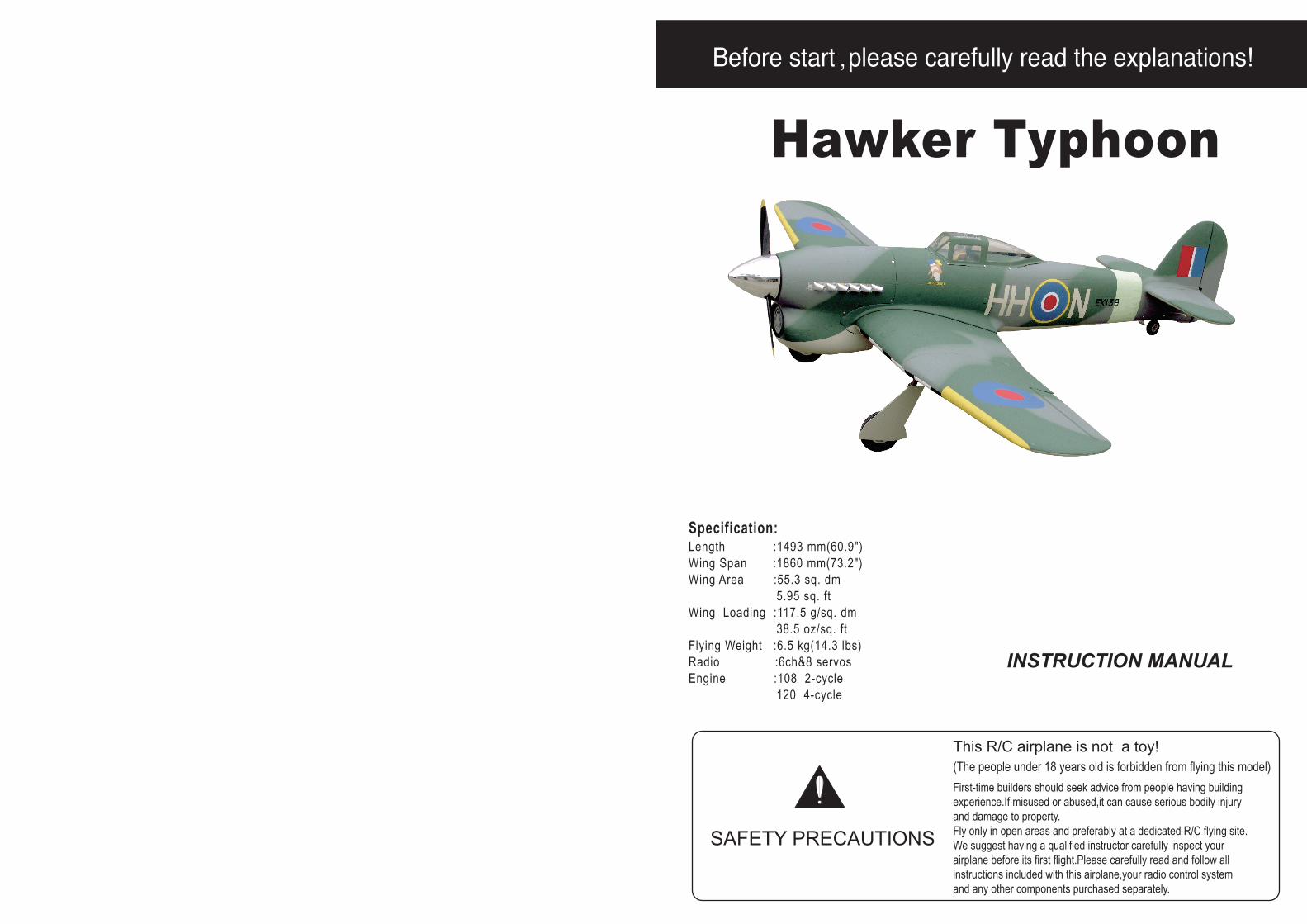
Hawker Typhoon
Specification:Length :1493 mm(60.9")Wing Span :1860 mm(73.2")Wing Area :55.3 sq. dm 5.95 sq. ftWing Loading :117.5 g/sq. dm 38.5 oz/sq. ftFlying Weight :6.5 kg(14.3 lbs)Radio :6ch&8 servosEngine :108 2-cycle 120 4-cycle
SAFETY PRECAUTIONS
INSTRUCTION MANUAL
First-time builders should seek advice from people having building experience.If misused or abused,it can cause serious bodily injury and damage to property.Fly only in open areas and preferably at a dedicated R/C flying site.We suggest having a qualified instructor carefully inspect your airplane before its first flight.Please carefully read and follow all instructions included with this airplane,your radio control system and any other components purchased separately.
(The people under 18 years old is forbidden from flying this model)This R/C airplane is not a toy!
: 4-cycle .120
15"X7
6
(with 9 servos),6
6
6 channel radio for aiplane is highly recommended for this model.
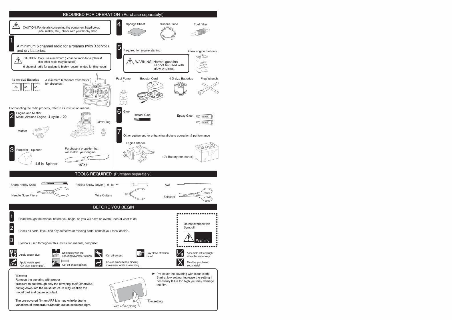
WarningRemove the covering with proper pressure to cut through only the covering itself.Otherwise,cutting down into the balsa structure may weaken the model part and cause accident.
The pre-covered film on ARF kits may wrinkle due to variations of temperature.Smooth out as explained right.
4.5 in Spinner
Apply epoxy glue.
Pre-cover the covering with clean cloth!Start at low setting. Increase the setting ifnecessary.If it is too high,you may damagethe film.
Iow settingwith cover(cloth)
6Pin hinge(24x24mm)
Make sure hinges are mounted in the same line.
Securely glue together. If coming off during flights, you 'lllose control of your airplane which leads to accidents!
8
6
22
2
4
2
4
2
2
Clevis
Rod (2x300mm) Retainer
TP Screw (2.3x12mm)
Wooden Block(20x20x8mm)Servo tray(68.5x56.5x2mm)
Pin hinge(24x24mm)
Screw (3x35mm)
Washer(3x15mm)
2Washer(3x15mm)Lock Nut (3mm )
Clevis
Retainer Rod (2x300mm)
Screw (2x10mm)
4Wood dowel (6x30mm)
1Rib template (2mm ply)
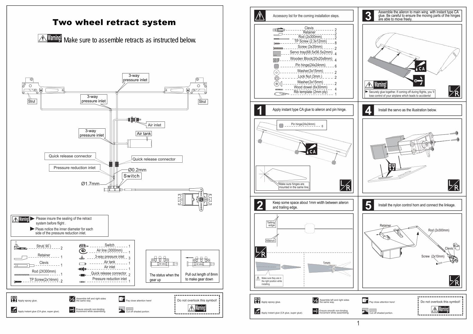
Install the servo as the illustration below.
Install the nylon control horn and connect the linkage.
Apply instant type CA glue to aileron and pin hinge.
1mm
Aileron
Tailing edge
Make sure they are inthe right position whileinstalling.
Keep some space about 1mm width between aileron and trailing edge.
Assemble the aileron to main wing with instant type CA glue. Be careful to ensure the moving parts of the hinges are able to move freely.
1
2
3
4
5
1
Accessory list for the coming installation steps.
Air tank
Switch
Air inlet
3-waypressure inlet
3-waypressure inlet
3-waypressure inlet
The status when thegear up
Pull out length of 8mm to make gear down
Air valve Air valve
Make sure to assemble retracts as instructed below.
Two wheel retract system
Quick release connector Quick release connector
Pressure reduction inlet
Strut Strut
3-way pressure inlet 3
Pressure reduction inlet 1
1Air tank1Air inlet
2 11Air line (3000mm)
2Quick release connector
Strut( 90 ) Switch
Clevis
Rod (2X300mm)
1
1
1
Retainer
TP Screw(2x14mm) 2
Ø1.7mm
Ø0.2mm
Pleas notice the inner diameter for each side of the pressure reduction inlet.
Please insure the sealing of the retract system before flight .
1.5mm
3mm
TP Screw (2.3x12mm)
12Pin hinge(36x20x1mm)
12
Steel wire (1.5x200mm) 2Pin hinge(36x20x1mm)
8
22
2
4
2
4
2
2
Clevis
Rod (2x300mm) Retainer
TP Screw (2.3x12mm)
Wooden Block(20x20x8mm)Servo tray(68.5x56.5x2mm)
Screw (3x35mm)
Washer(3x15mm)
2Washer(3x15mm)Lock Nut (3mm )
Rod (2x300mm)
Clevis
Washer(3x15mm)
Washer
Lock Nut (3mm )
Screw (3x35mm)
Screw (2x10mm)
6mm
Rib template (2mm ply)
Rib template (2mm ply)
4Wood dowel (6x30mm)
1Rib template (2mm ply)
6mm
Securely glue together. If coming off during flights, you 'lllose control of your airplane which leads to accidents!
A A"A = A"
Main wing joiner2
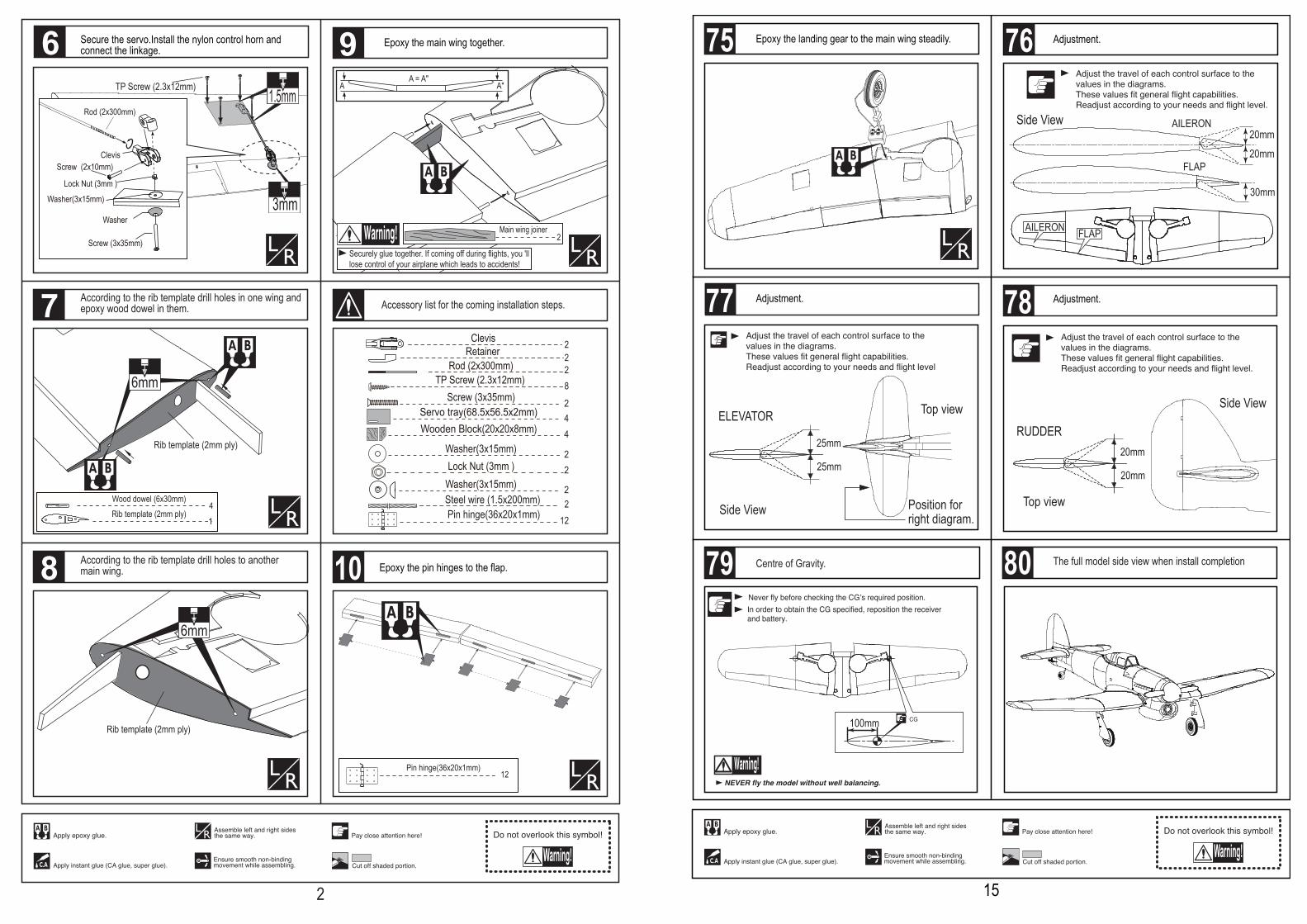
Epoxy the pin hinges to the flap.
Secure the servo.Install the nylon control horn and connect the linkage.
Epoxy the main wing together.
Accessory list for the coming installation steps.According to the rib template drill holes in one wing andepoxy wood dowel in them.
According to the rib template drill holes to another main wing.
7
8
6 9
10
2
Top view
Position forright diagram.
ELEVATOR
Side View
25mm
25mm
100mm
Top view
Side View
20mm
20mm
RUDDER
20mm
20mm
30mm
AILERON
FLAP
FLAPAILERON
Side View
Centre of Gravity. The full model side view when install completion
Adjustment.
Epoxy the landing gear to the main wing steadily. Adjustment.
Adjustment.77
79
76
15
75
78
80
TP Screw (2.3x12mm)
Steel wire
27mm
1.5mm
3mm
2Steel wire (1.5x200mm)
Securely glue together. If coming off during flights, you 'lllose control of your airplane which leads to accidents!
Rod (2x300mm)
Clevis
Washer(3x15mm)
Washer
Lock Nut (3mm )
Screw (3x35mm)
Clevis
Retainer Rod (2x300mm)
Screw (2x10mm)
Screw (2x10mm)
Flap
Trailing edge
Make sure they are inthe right position whileinstalling.
1mm
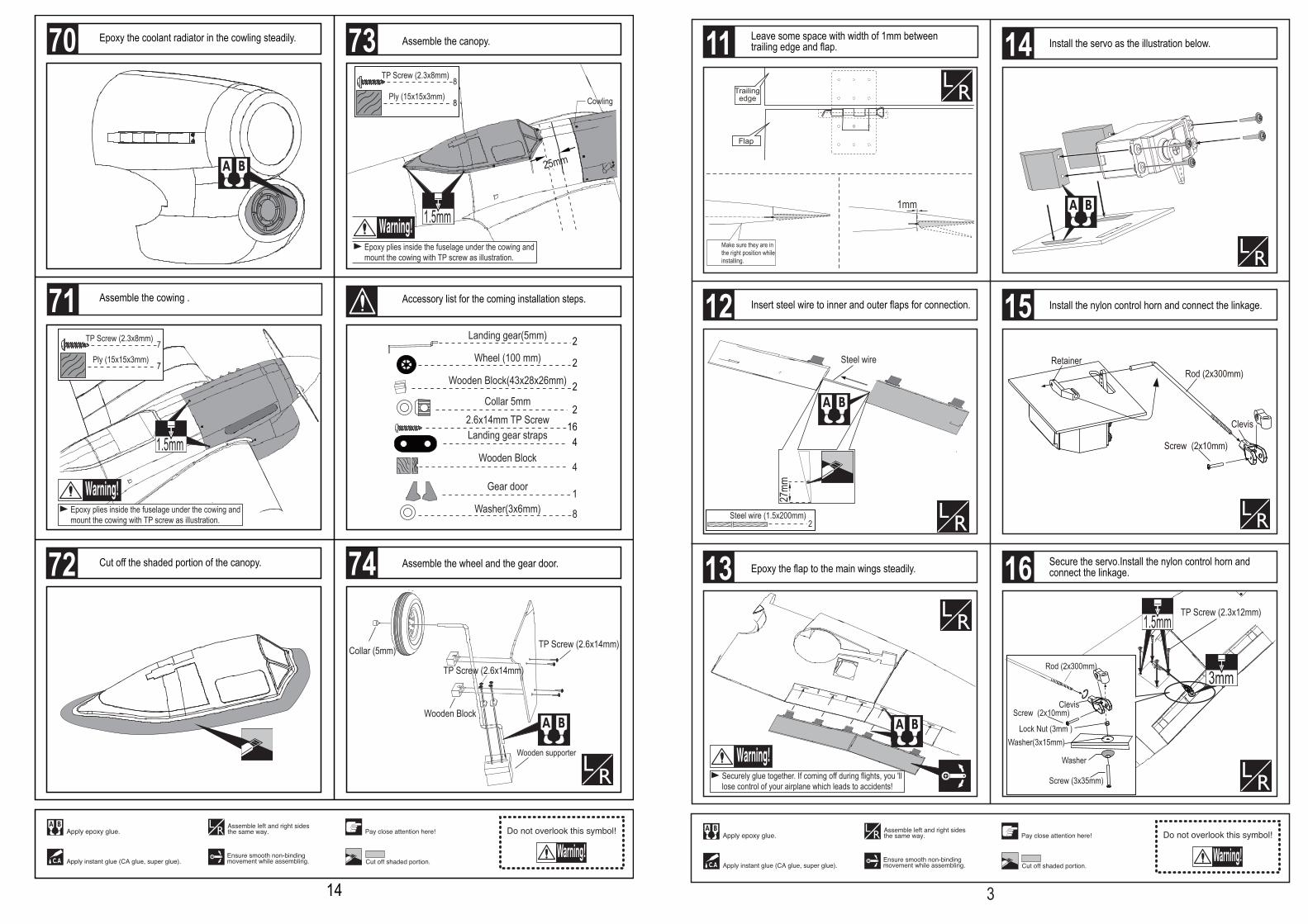
Leave some space with width of 1mm between trailing edge and flap.
Insert steel wire to inner and outer flaps for connection.
Epoxy the flap to the main wings steadily.
Install the servo as the illustration below.
Install the nylon control horn and connect the linkage.
Secure the servo.Install the nylon control horn and connect the linkage.
12
13
14
15
16
3
11
TP Screw (2.6x14mm)
Wooden Block
TP Screw (2.6x14mm)
Collar (5mm)
Wooden supporter
1.5mm
8TP Screw (2.3x8mm)
Ply (15x15x3mm)8
Epoxy plies inside the fuselage under the cowing and mount the cowing with TP screw as illustration.
162.6x14mm TP ScrewLanding gear straps 4
Collar 5mm2
Wooden Block(43x28x26mm) 2
2Wheel (100 mm)
Landing gear(5mm) 2
1Gear door
4Wooden Block
Washer(3x6mm) 8
Cut off the shaded portion of the canopy.
Cowling
25mm
7TP Screw (2.3x8mm)
Ply (15x15x3mm)7
1.5mm
Epoxy plies inside the fuselage under the cowing and mount the cowing with TP screw as illustration.
Assemble the wheel and the gear door.
Epoxy the coolant radiator in the cowling steadily.
Assemble the cowing .
Assemble the canopy.
Accessory list for the coming installation steps.71
73
72 74
14
70

B = B 'A = A '
Drill 6.2mm holes at the placeof main wing.
Install the wing to the fuselagewith 6x50mm screws as shown in the diagrams below.
B`B
A`A
Screw (3x10mm)
Retracts strut
LockNut(4mm)
Wooden Block
2Wood dowel (6x50mm)
22Blind Nut (6mm)
Screw (6x50mm)
1Gear door
2Wheel (100mm)
84
Screw (3x10mm )Landing gear straps
2LockNut (4mm)2PVC
2Bushing (8X4mm)
Bushing (8X4mm)
1Reinforcement plate
4Wooden Block(25x15x13mm)
Note:rubber wheels oleo struts and retracts are optional.
Assembly of the main wings. Cut off the surplus PVC part carefully along the shaded line
Cut away the film on the position for the air retract landing.
Epoxy the wheel house to relevant position.Assemble the gear doors and the wheels to the retracts.
Accessory list for the coming installation steps.
17
18
19
20
21
4
2Pvc part
1Canopy
Coolant radiator1
15TP Screw (2.3x8mm)
Ply (15x15x3mm)15
15mm
Trim the coolant radiator.Trim the cowling for engine muffler.
Be care to notice the distance between the wheel andfuselage.
Accessory list for the coming installation steps. Epoxy the exhaust to the cowling from inner of the cowing.
Cut off the surplus parts carefully along the shaded line.
67
68
69
70
13
66
150mm
50mmCenter line
TP Screw (3x20mm)
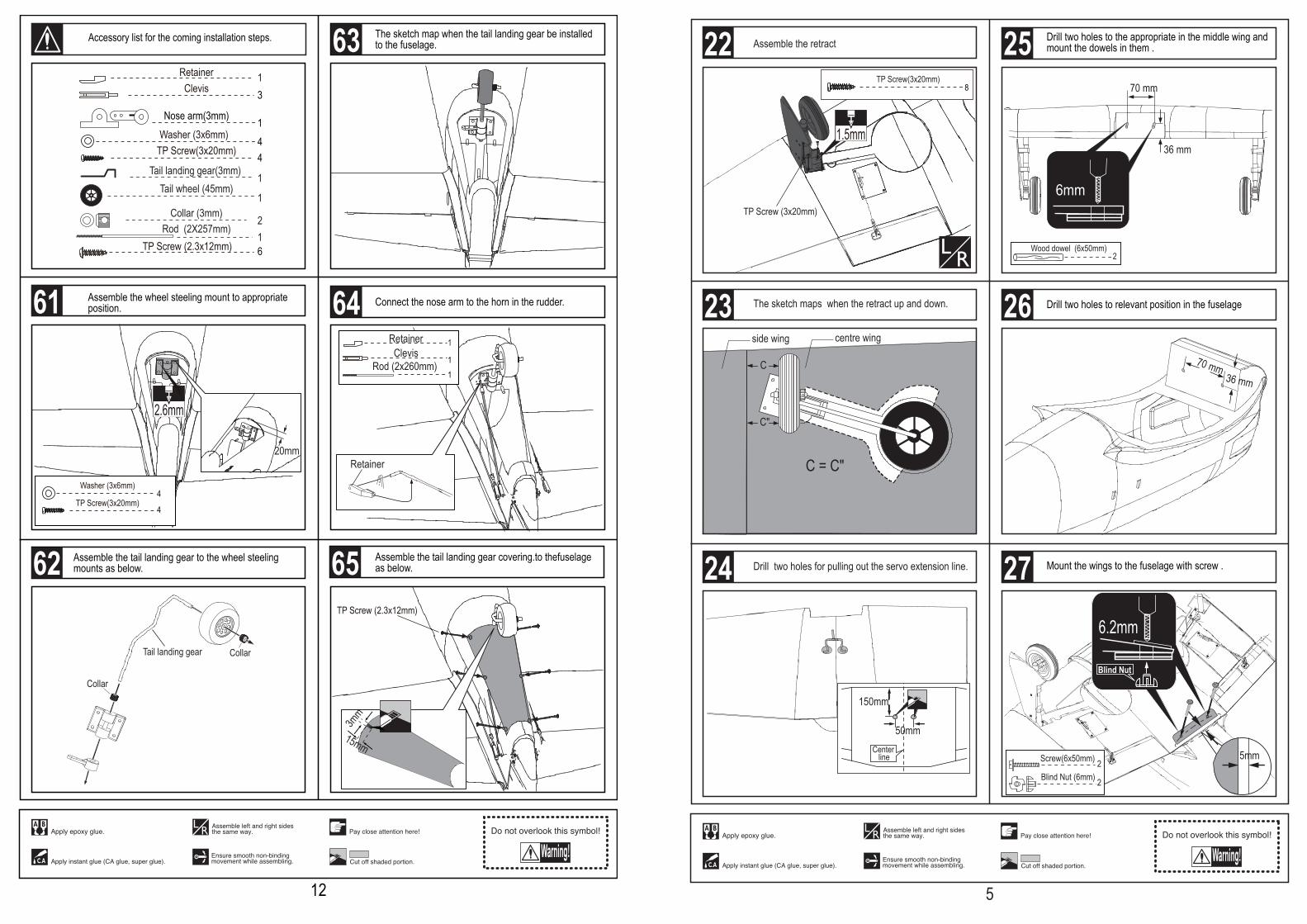
The sketch maps when the retract up and down.
Assemble the retract
Drill two holes for pulling out the servo extension line.
70 mm
36 mm
2Wood dowel (6x50mm)
6.2mm
Blind Nut
2
2Blind Nut (6mm)
Screw(6x50mm)
6mm
70 mm36 mm
5mm
C"
C = C"
C
side wing centre wing
1.5mm
TP Screw(3x20mm)8
Drill two holes to the appropriate in the middle wing and mount the dowels in them .
Drill two holes to relevant position in the fuselage
Mount the wings to the fuselage with screw .
23
24
22
26
25
27
5
Retainer
Clevis1
1Retainer
Rod (2x260mm) 1
Connect the nose arm to the horn in the rudder.
3mm
15mm
Collar Tail landing gear
Collar
Assemble the tail landing gear to the wheel steelingmounts as below.
The sketch map when the tail landing gear be installed to the fuselage.
TP Screw (2.3x12mm)
TP Screw(3x20mm)
Washer (3x6mm)
4
4
1Nose arm(3mm)
Collar (3mm) 2
1
1Tail landing gear(3mm) Tail wheel (45mm)
Clevis 31Retainer
Rod (2X257mm)1
TP Screw(3x20mm)Washer (3x6mm)
44
6TP Screw (2.3x12mm)
20mm
2.6mm
Assemble the tail landing gear covering.to thefuselage as below.
Assemble the wheel steeling mount to appropriateposition.
Accessory list for the coming installation steps.
61
62
63
65
12
64
1Stab joiner (16x280mm)
4
3
2
Pin hinge(24x24mm)
Make sure hinges are mounted in the same line.
4Pin hinge(24x24mm)
Pin hinge(2.5x48mm)
3
Using rubber tubu coverthe middle of the hingesbefore installation in casethe epoxy glue get into.
Pin hinge(2.5x48mm)
Make sure hinges are mounted in the same line.
1mm
Rudder
Tailing edge
Cut away the rubber tube whenthe epoxy glue dried.
Make sure they are inthe right position whileinstalling.
Steel wire (0.5x3000mm)
1U-style wire (3mm)
Drill holes for easy assembly of the belly pants
2.5mm
2.5mm
4Matal douel (4x30mm)
1Rib template (3mm ply)
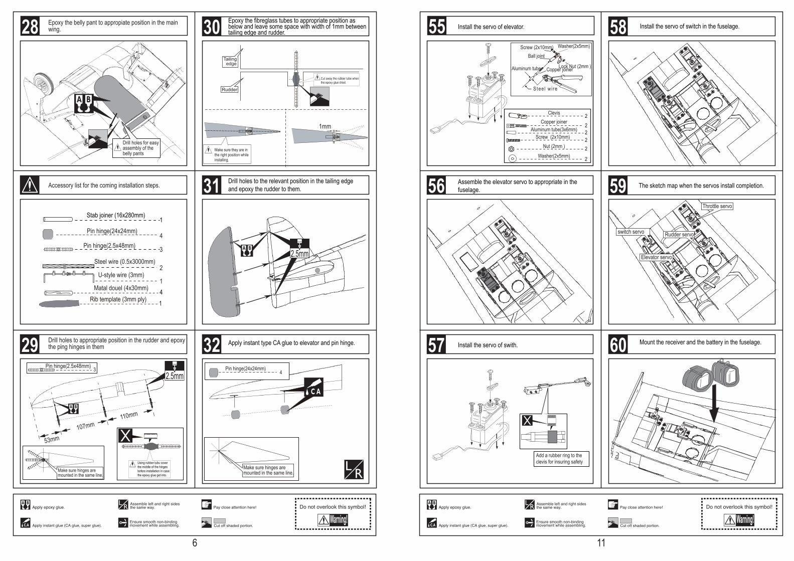
Epoxy the fibreglass tubes to appropriate position as below and leave some space with width of 1mm between tailing edge and rudder.
Accessory list for the coming installation steps.
Drill holes to appropriate position in the rudder and epoxythe ping hinges in them
Epoxy the belly pant to appropiate position in the main wing.
Apply instant type CA glue to elevator and pin hinge.
53mm107mm
110mm
Drill holes to the relevant position in the tailing edge and epoxy the rudder to them.
29
30
31
32
6
28
Add a rubber ring to theclevis for insuring safety
Throttle servo
Elevator servo
switch servo Rudder servo
2
22
ClevisCopper joiner
Aluminum tube(3x6mm)
22
Screw (2x10mm) Nut (2mm )
2Washer(2x5mm)
Stee l w i re
Copper joinerAluminum tube Lock Nut (2mm )
Screw (2x10mm)Ball joint
Washer(2x5mm)
Install the servo of swith.
Install the servo of switch in the fuselage.
The sketch map when the servos install completion.
Mount the receiver and the battery in the fuselage.
Install the servo of elevator.
Assemble the elevator servo to appropriate in the fuselage.
56
57
5855
60
11
59
Elevator
1mm
Tailing edge
Make sure they are inthe right position whileinstalling.
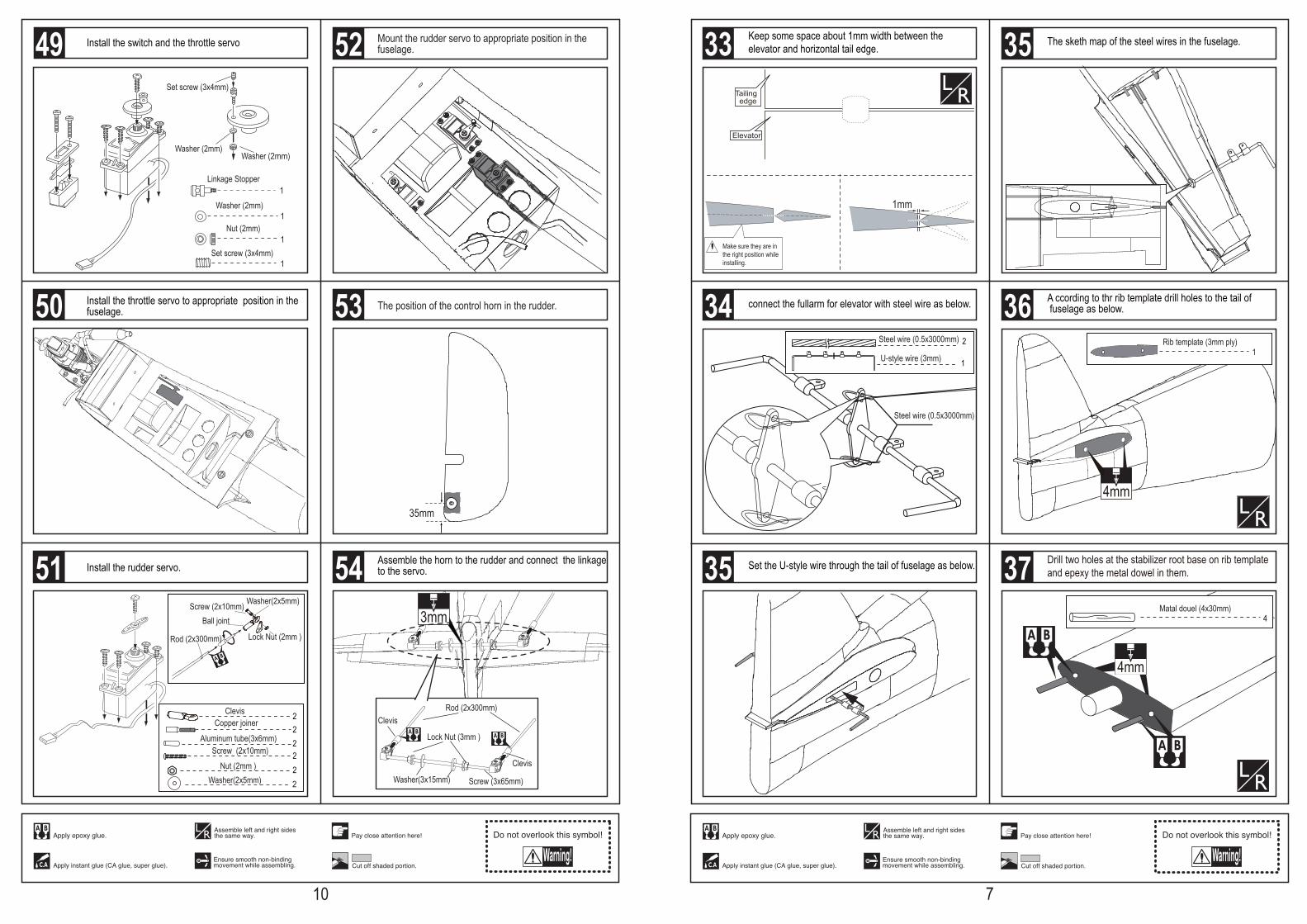
Keep some space about 1mm width between the elevator and horizontal tail edge. The sketh map of the steel wires in the fuselage.
connect the fullarm for elevator with steel wire as below.
2
1
Steel wire (0.5x3000mm)
Steel wire (0.5x3000mm)
U-style wire (3mm)
4mm
4mm
4Matal douel (4x30mm)
1Rib template (3mm ply)
Set the U-style wire through the tail of fuselage as below. Drill two holes at the stabilizer root base on rib templateand epexy the metal dowel in them.
A ccording to thr rib template drill holes to the tail of fuselage as below.34
33
35
35
36
37
7
35mm
3mm
Rod (2x300mm)
Lock Nut (3mm )
Washer(3x15mm)
Clevis
Clevis
Screw (3x65mm)
Linkage Stopper
Washer (2mm)
Washer (2mm)
Nut (2mm)
Set screw (3x4mm)
Washer (2mm)
Set screw (3x4mm)
1
1
1
1
Rod (2x300mm) Lock Nut (2mm )
Screw (2x10mm)Ball joint
Washer(2x5mm)
2
2
Clevis
Aluminum tube(3x6mm)
22
Screw (2x10mm) Nut (2mm )
2Copper joiner
2Washer(2x5mm)
Mount the rudder servo to appropriate position in the fuselage.
The position of the control horn in the rudder.
Assemble the horn to the rudder and connect the linkage to the servo.
Install the switch and the throttle servo
Install the throttle servo to appropriate position in the fuselage.
Install the rudder servo.
50
51
52
53
54
10
49
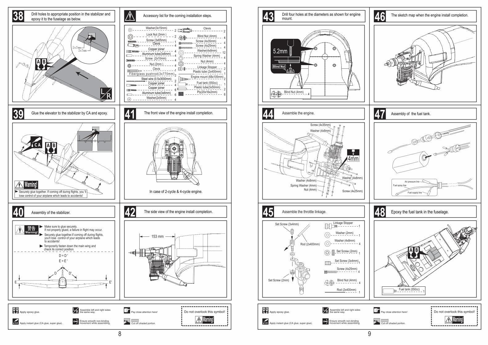
153 mm
In case of 2-cycle & 4-cycle engine.
E'
D D'
E
D = D 'E = E '
Make sure to glue securely.If not properly glued, a failure in flight may occur.
Temporarily fasten down the main wing and check its correct position.
Securely glue together.If coming off during flights,you'll lose control of your airplane which leads to accidents!
4Blind Nut (4mm)
1Engine mount (68x105mm)
Linkage Stopper4
412
4
Washer(4x8mm)
Screw (4x35mm)
Spring Washer (4mm) Nut (4mm)
2
4Screw (4x25mm)
2
Plastic tube (2x400mm)
Fuel tank (550cc) 1
1ClevisF iberg lass pushrod(3x770mm) 2
24
Steel wire (0.5x3000mm)Copper joiner
66
Copper joinerAluminum tube(3x6mm)
2Plastic tube(3x50mm)
6Ply(20x16x2mm)
22
2
ClevisWasher(3x15mm)
Lock Nut (3mm )
1Screw (3x65mm)4
44
ClevisCopper joiner
Aluminum tube(3x6mm)
44
Screw (2x10mm) Nut (2mm )
Securely glue together. If coming off during flights, you 'lllose control of your airplane which leads to accidents!
2x7mm2x7mm
4Washer(2x5mm)
The front view of the engine install completion.
The side view of the engine install completion.
Accessory list for the coming installation steps.
Assembly of the stabilizer.
Drill holes to appropriate position in the stabilizer and epoxy it to the fuselage as below.
Glue the elevator to the stabilizer by CA and epoxy.
38
40
41
42
8
39
Fuel supply line
Fuel spray lineAir pressure line
Fuel tank (550cc) 1
Set Screw (3x4mm)
Set Screw (2mm)
Rod (2x400mm)
Set Screw (2mm)
Washer (2mm)
Linkage Stopper1
1
1
1
1
4
4
Washer (4x8mm)4
Rod (2x400mm)
Blind Nut (4mm)
Screw (4x25mm)
Set Screw (3x4mm)
Washer (4x8mm)
Washer (4x8mm)Washer (4x8mm)
Screw (4x35mm)
Screw (4x25mm)Nut (4mm)Spring Washer (4mm)
4mm
5.2mm
Blind Nut
4Blind Nut (4mm)
The sketch map when the engine install completion.
Assembly of the fuel tank.
Epoxy the fuel tank in the fuselage.
Assemble the engine.
Drill four holes at the diameters as shown for engiine mount.
Assemble the throttle linkage.
44
45
46
47
48
9
43


![Hawker Typhoon - $8 - Daruma Sushi · Hawker Typhoon | Aircraft | 11/04/2012 15:56:06] The turning point in the Typhoon's career came in](https://img.pdfslide.us/doc/110x75/5af2e2727f8b9aa91690f292/hawker-typhoon-8-daruma-typhoon-aircraft-11042012-155606-the-turning.jpg)