Embed Size (px)
Citation preview
Page 1FAA ApprovedRevision A3: Mar 22, 2005
Hawker 800XP Pro Line 21 Airplane Flight Manual
SECTION 2
LIMITATIONS
Table of Contents
Page
KINDS OF OPERATION.................................................................................... 3WEIGHT LIMITATIONS ..................................................................................... 3PERFORMANCE LIMITATIONS ....................................................................... 3
Take-off Weight........................................................................................... 3 Landing Weight .......................................................................................... 3Take-off Field Length .................................................................................. 4
OPERATIONAL LIMITATIONS.......................................................................... 4Altitude ........................................................................................................ 4Maximum Permissible Altitude .................................................................... 4Air Temperature .......................................................................................... 4Wind Component ........................................................................................ 4Runway Slope ............................................................................................. 5Airplane Configurations............................................................................... 5
COMPARTMENT LOADING LIMITATIONS ...................................................... 5LOAD LIMITATIONS.......................................................................................... 5
Center of Gravity Limitations....................................................................... 5Figure 2.1 - LOADING and FLIGHT ENVELOPE - POUNDS/FEET ................................................................................. 6Figure 2.2 - LOADING and FLIGHT ENVELOPE - KILOGRAMS/METERS ..................................................................... 7
ICE PROTECTION LIMITATIONS..................................................................... 9Icing General............................................................................................... 9Airframe Icing .............................................................................................. 9Wing/Tail Antice System ............................................................................. 9Engine Icing ................................................................................................ 9
SEVERE ICING CONDITIONS LIMITATIONS ................................................ 10ENGINE LIMITATIONS.................................................................................... 11
Engine Type .............................................................................................. 11Engine Limitations..................................................................................... 11Approved Engine Oils ............................................................................... 12Engine Oil Consumption ........................................................................... 12Engine Fuel Computer .............................................................................. 12Engine Synchronizer ................................................................................. 12Automatic Performance Reserve (APR) ................................................... 12Engine Instrument Markings ..................................................................... 12Thrust Reversers....................................................................................... 12Engine Ice Protection System................................................................... 13
FUEL LIMITATIONS ........................................................................................ 13Fuel Specifications .................................................................................... 13Fuel Additives............................................................................................ 14Maximum Fuel Temperature ..................................................................... 15
Page 2 Section - 2LIMITATIONS
FAA Approved Revision A3: Mar 22, 2005
Hawker 800XP Pro Line 21 Airplane Flight Manual
PageMinimum Fuel Temperature...................................................................... 15Fuel Quantity............................................................................................. 15Fuel Loading ............................................................................................. 16Pressure Refueling ................................................................................... 16Fuel System Management ........................................................................ 16
ELECTRICAL LIMITATIONS ........................................................................... 16Battery Limitations .................................................................................... 16Generator Limitations................................................................................ 16Main Engine Starter Duty Cycle................................................................ 16Operation of Electrical Circuit Breakers .................................................... 16
AVIONICS LIMITATIONS ................................................................................ 17General ..................................................................................................... 17HF Radio................................................................................................... 17Electronic Standby Instrument System (ESIS) ......................................... 17Flight Management System ...................................................................... 17Autopilot .................................................................................................... 19VNAV ........................................................................................................ 20EGPWS..................................................................................................... 21TCAS II ..................................................................................................... 21
AIRSPEED LIMITATIONS ............................................................................... 22Maximum Operating Speed ...................................................................... 22Maximum Operating Mach Number .......................................................... 22Maneuvering Speed.................................................................................. 22Wing Flaps Extended/Operating Speed.................................................... 22Procedural Use of Flaps 15° for Descent and Holding ............................. 22Air Brakes ................................................................................................. 23Landing Gear Extended/Operating Speed................................................ 23Bird Strike Speed ...................................................................................... 23
MISCELLANEOUS LIMITATIONS................................................................... 25Air Brakes ................................................................................................. 25Cabin Emergency Overwing Exit .............................................................. 25Cabin High Datum..................................................................................... 25Crew Seats ............................................................................................... 25Inter-compartment Door............................................................................ 25Lift Dump................................................................................................... 25Maneuvering Load Factor Limitations....................................................... 25Minimum Flight Crew ................................................................................ 25Nosewheel Tires ....................................................................................... 25Number of Occupants ............................................................................... 25Pressure Cabin ......................................................................................... 25Rudder Bias .............................................................................................. 25Smoking .................................................................................................... 26System Gage Markings............................................................................. 26Weather Radar.......................................................................................... 26Wheel Brakes............................................................................................ 26
Table 1 - Take-off Weights for Wheel Brakes Waiting Periods .................................. 27
Page 3Section - 2LIMITATIONS
FAA Approved Revision A3: Mar 22, 2005
Hawker 800XP Pro Line 21 Airplane Flight Manual
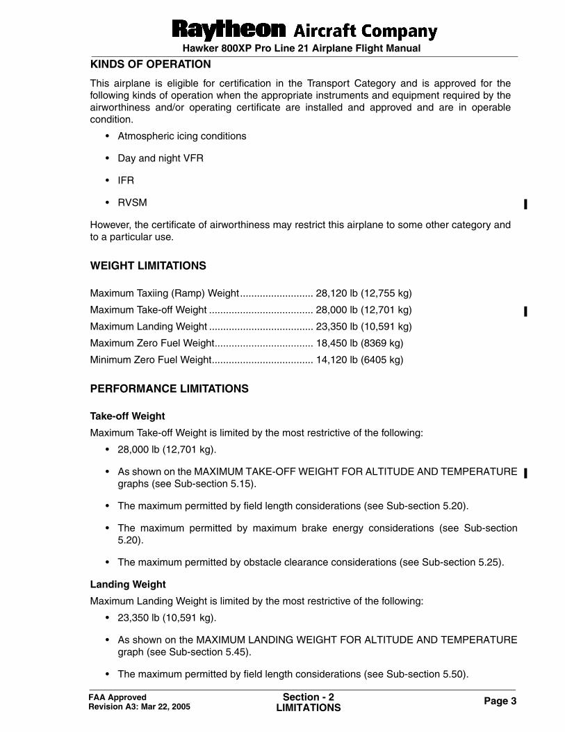
KINDS OF OPERATION
This airplane is eligible for certification in the Transport Category and is approved for thefollowing kinds of operation when the appropriate instruments and equipment required by theairworthiness and/or operating certificate are installed and approved and are in operablecondition.
• Atmospheric icing conditions
• Day and night VFR
• IFR
• RVSM
However, the certificate of airworthiness may restrict this airplane to some other category andto a particular use.
WEIGHT LIMITATIONS
Maximum Taxiing (Ramp) Weight.......................... 28,120 lb (12,755 kg)
Maximum Take-off Weight ..................................... 28,000 lb (12,701 kg)
Maximum Landing Weight ..................................... 23,350 lb (10,591 kg)
Maximum Zero Fuel Weight................................... 18,450 lb (8369 kg)
Minimum Zero Fuel Weight.................................... 14,120 lb (6405 kg)
PERFORMANCE LIMITATIONS
Take-off Weight
Maximum Take-off Weight is limited by the most restrictive of the following:
• 28,000 lb (12,701 kg).
• As shown on the MAXIMUM TAKE-OFF WEIGHT FOR ALTITUDE AND TEMPERATUREgraphs (see Sub-section 5.15).
• The maximum permitted by field length considerations (see Sub-section 5.20).
• The maximum permitted by maximum brake energy considerations (see Sub-section5.20).
• The maximum permitted by obstacle clearance considerations (see Sub-section 5.25).
Landing Weight
Maximum Landing Weight is limited by the most restrictive of the following:
• 23,350 lb (10,591 kg).
• As shown on the MAXIMUM LANDING WEIGHT FOR ALTITUDE AND TEMPERATUREgraph (see Sub-section 5.45).
• The maximum permitted by field length considerations (see Sub-section 5.50).
Page 4 Section - 2LIMITATIONS
FAA Approved Revision A3: Mar 22, 2005
Hawker 800XP Pro Line 21 Airplane Flight Manual
Take-off Field Length
The take-off weight shall not exceed the maximum permitted by field length considerations asdescribed in Sub-section 5.20 for the restricted range of conditions listed.
When complying with the above, the following conditions shall be met:
• The take-off distance used in the graphs shall not be greater than the length of runway plusthe length of clearway if present, except that the length of clearway shall not be greaterthan one-half of the length of the runway.
• The take-off run used in the graphs shall not be greater than the length of the runway.
OPERATIONAL LIMITATIONS
Altitude
Maximum/Minimum field pressure altitudesfor takeoff or landing............................................13,000 ft and -2000 ft
NOTE: Performance appropriate to the lowest published elevation shall be used when thefield pressure altitude is below the lowest published elevation.
Maximum Permissible Altitude
Maximum permissible operating altitude is 41,000 ft.
Maximum permissible altitude with flaps lowered or landing gear extended is 20,000 ft.
Air Temperature
Maximum
All Flight Regimes .............................................. ISA +35° C
Ground (prior to engine start):
Flight compartment exposed to direct sunlight (sky with less than 10% cloud cover)
• With flight compartment sunshields.......... ISA +35° C
• Without flight compartment sunshields..... ISA +31° C
Flight compartment exposed to indirect sunlight (sky with more than 10% cloud cover)
• ISA +35° C
NOTE: If sunshields are utilized, a sufficient quantity shall be installed to protect the entire flight compartment.
Minimum
• Takeoff/Landing........................................ -40° C
• Enroute..................................................... -75° C
NOTE: When the temperature is below the lowest scheduled, performance appropriate tothe lowest scheduled temperature shall be used.
Wind Component
The maximum tailwind component for takeoff and landing appropriate to a height of 33 ft (10.1 m) is 10 knots.
Page 5Section - 2LIMITATIONS
FAA Approved Revision A3: Mar 22, 2005
Hawker 800XP Pro Line 21 Airplane Flight Manual
Runway Slope
The maximum effective runway slopes for takeoff are 2% uphill and 2% downhill.
Airplane Configurations
The airplane configurations as stated in Sub-section 5.05 must be observed.
COMPARTMENT LOADING LIMITATIONS
The airplane must be loaded in accordance with Section 6 - WEIGHT & BALANCE of thisAirplane Flight Manual and as provided on placards in the Baggage/Stowage Compartments.
LOAD LIMITATIONS
Center Of Gravity Limitations
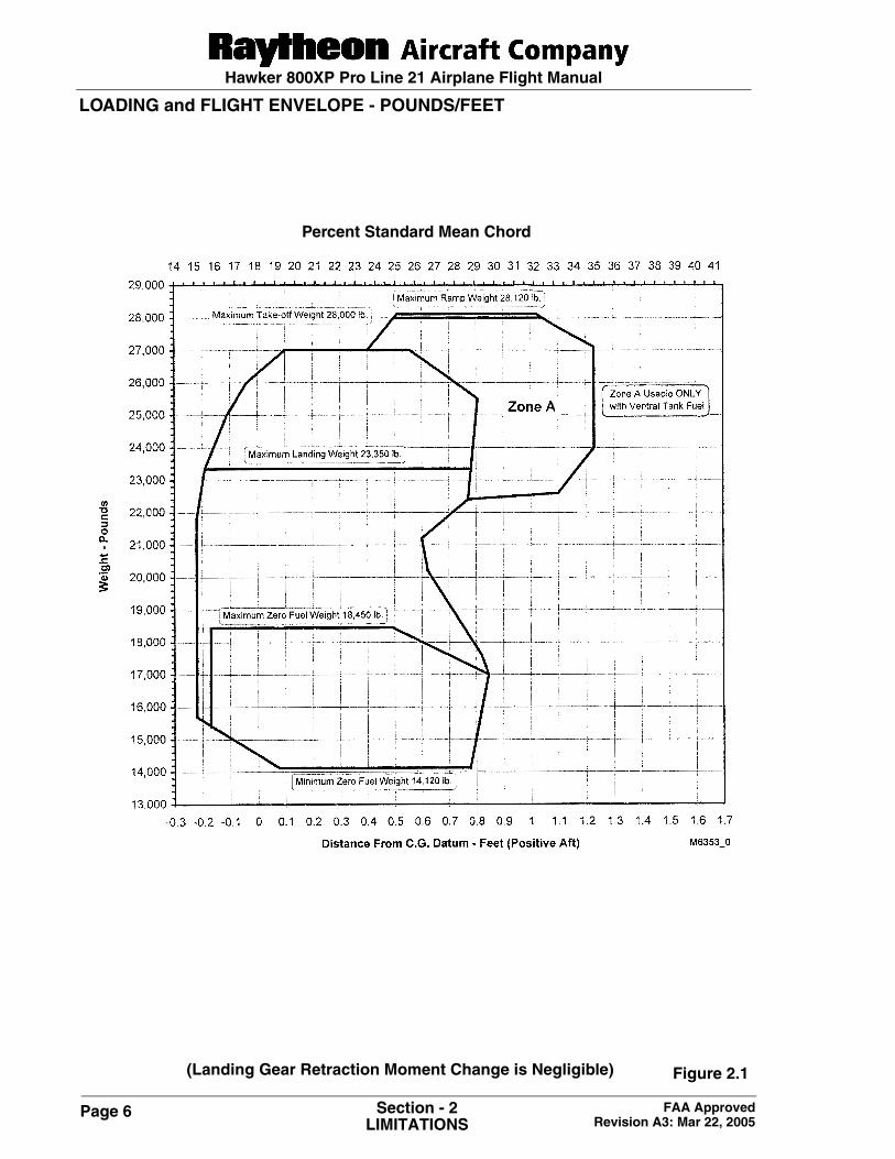
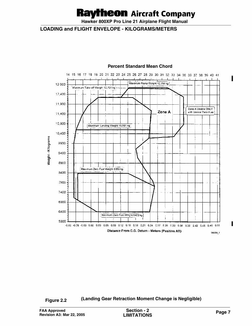
The center of gravity must always lie between the forward and aft limits as defined in theenvelope shown in Figures 2.1 and 2.2.
The limits apply with the landing gear up. The effect of the landing gear in the down position isnegligible.
The center of gravity datum is 11 ft (3.4 m) forward of the reference point on the fuselage. Thereference point is defined by a screw on the fuselage skin located beneath the right enginepod.
Page 6 Section - 2LIMITATIONS
FAA Approved Revision A3: Mar 22, 2005
Hawker 800XP Pro Line 21 Airplane Flight Manual
LOADING and FLIGHT ENVELOPE - POUNDS/FEET
(Landing Gear Retraction Moment Change is Negligible)
Percent Standard Mean Chord
Figure 2.1
Page 7Section - 2LIMITATIONS
FAA Approved Revision A3: Mar 22, 2005
Hawker 800XP Pro Line 21 Airplane Flight Manual
LOADING and FLIGHT ENVELOPE - KILOGRAMS/METERS
Percent Standard Mean Chord
(Landing Gear Retraction Moment Change is Negligible)Figure 2.2
Page 8 Section - 2LIMITATIONS
FAA Approved Revision A3: Mar 22, 2005
Hawker 800XP Pro Line 21 Airplane Flight Manual
Intentionally left blank
Page 2 of 3 P/N 140-590032-0005TC16 (Issue 2)March 2, 2006
SECTION 2 - LIMITATIONS
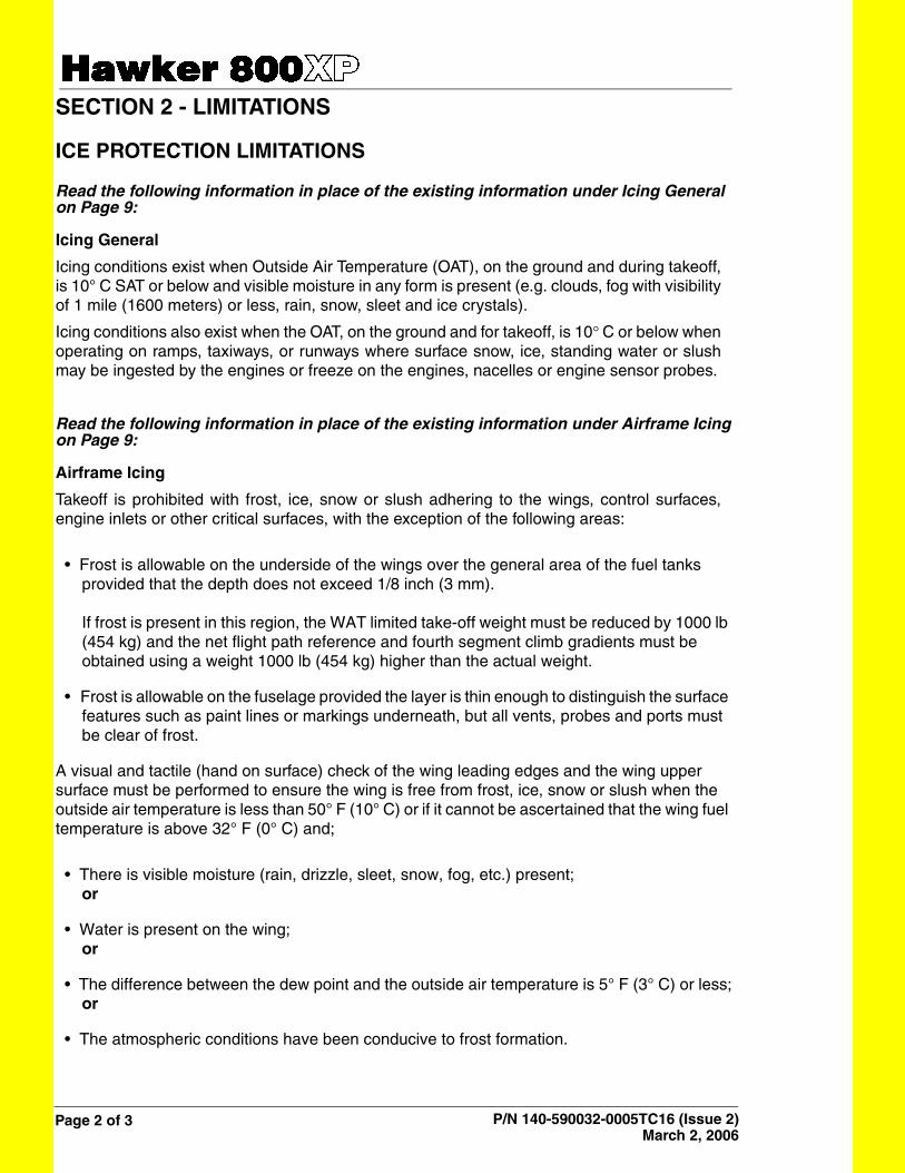
ICE PROTECTION LIMITATIONS
Read the following information in place of the existing information under Icing General on Page 9:
Icing General
Icing conditions exist when Outside Air Temperature (OAT), on the ground and during takeoff,is 10° C SAT or below and visible moisture in any form is present (e.g. clouds, fog with visibilityof 1 mile (1600 meters) or less, rain, snow, sleet and ice crystals).
Icing conditions also exist when the OAT, on the ground and for takeoff, is 10 C or below whenoperating on ramps, taxiways, or runways where surface snow, ice, standing water or slushmay be ingested by the engines or freeze on the engines, nacelles or engine sensor probes.
Read the following information in place of the existing information under Airframe Icingon Page 9:
Airframe Icing
Takeoff is prohibited with frost, ice, snow or slush adhering to the wings, control surfaces,engine inlets or other critical surfaces, with the exception of the following areas:
• Frost is allowable on the underside of the wings over the general area of the fuel tanks provided that the depth does not exceed 1/8 inch (3 mm).
If frost is present in this region, the WAT limited take-off weight must be reduced by 1000 lb (454 kg) and the net flight path reference and fourth segment climb gradients must be obtained using a weight 1000 lb (454 kg) higher than the actual weight.
• Frost is allowable on the fuselage provided the layer is thin enough to distinguish the surface features such as paint lines or markings underneath, but all vents, probes and ports must be clear of frost.
A visual and tactile (hand on surface) check of the wing leading edges and the wing upper surface must be performed to ensure the wing is free from frost, ice, snow or slush when the outside air temperature is less than 50° F (10° C) or if it cannot be ascertained that the wing fuel temperature is above 32° F (0° C) and;
• There is visible moisture (rain, drizzle, sleet, snow, fog, etc.) present;or
• Water is present on the wing;or
• The difference between the dew point and the outside air temperature is 5° F (3° C) or less;or
• The atmospheric conditions have been conducive to frost formation.
Page 9Section - 2LIMITATIONS
FAA Approved Revision A3: Mar 22, 2005
Hawker 800XP Pro Line 21 Airplane Flight Manual
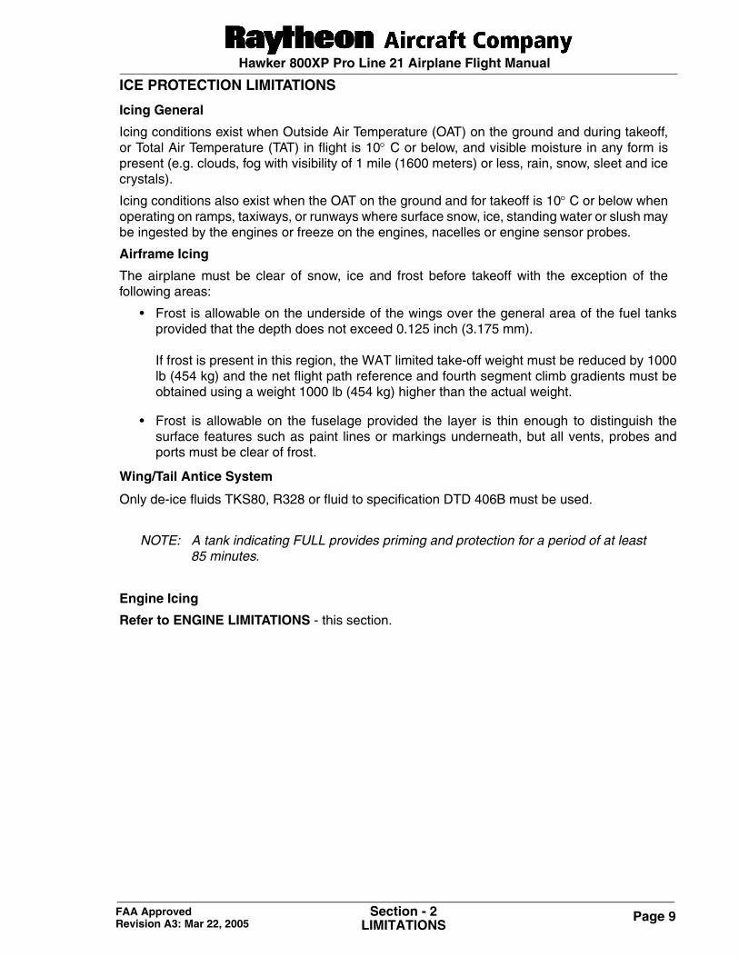
ICE PROTECTION LIMITATIONS
Icing General
Icing conditions exist when Outside Air Temperature (OAT) on the ground and during takeoff,or Total Air Temperature (TAT) in flight is 10° C or below, and visible moisture in any form ispresent (e.g. clouds, fog with visibility of 1 mile (1600 meters) or less, rain, snow, sleet and icecrystals).
Icing conditions also exist when the OAT on the ground and for takeoff is 10° C or below whenoperating on ramps, taxiways, or runways where surface snow, ice, standing water or slush maybe ingested by the engines or freeze on the engines, nacelles or engine sensor probes.
Airframe Icing
The airplane must be clear of snow, ice and frost before takeoff with the exception of thefollowing areas:
• Frost is allowable on the underside of the wings over the general area of the fuel tanksprovided that the depth does not exceed 0.125 inch (3.175 mm).
If frost is present in this region, the WAT limited take-off weight must be reduced by 1000lb (454 kg) and the net flight path reference and fourth segment climb gradients must beobtained using a weight 1000 lb (454 kg) higher than the actual weight.
• Frost is allowable on the fuselage provided the layer is thin enough to distinguish thesurface features such as paint lines or markings underneath, but all vents, probes andports must be clear of frost.
Wing/Tail Antice System
Only de-ice fluids TKS80, R328 or fluid to specification DTD 406B must be used.
NOTE: A tank indicating FULL provides priming and protection for a period of at least85 minutes.
Engine Icing
Refer to ENGINE LIMITATIONS - this section.
Page 10 Section - 2LIMITATIONS
FAA Approved Revision A3: Mar 22, 2005
Hawker 800XP Pro Line 21 Airplane Flight Manual
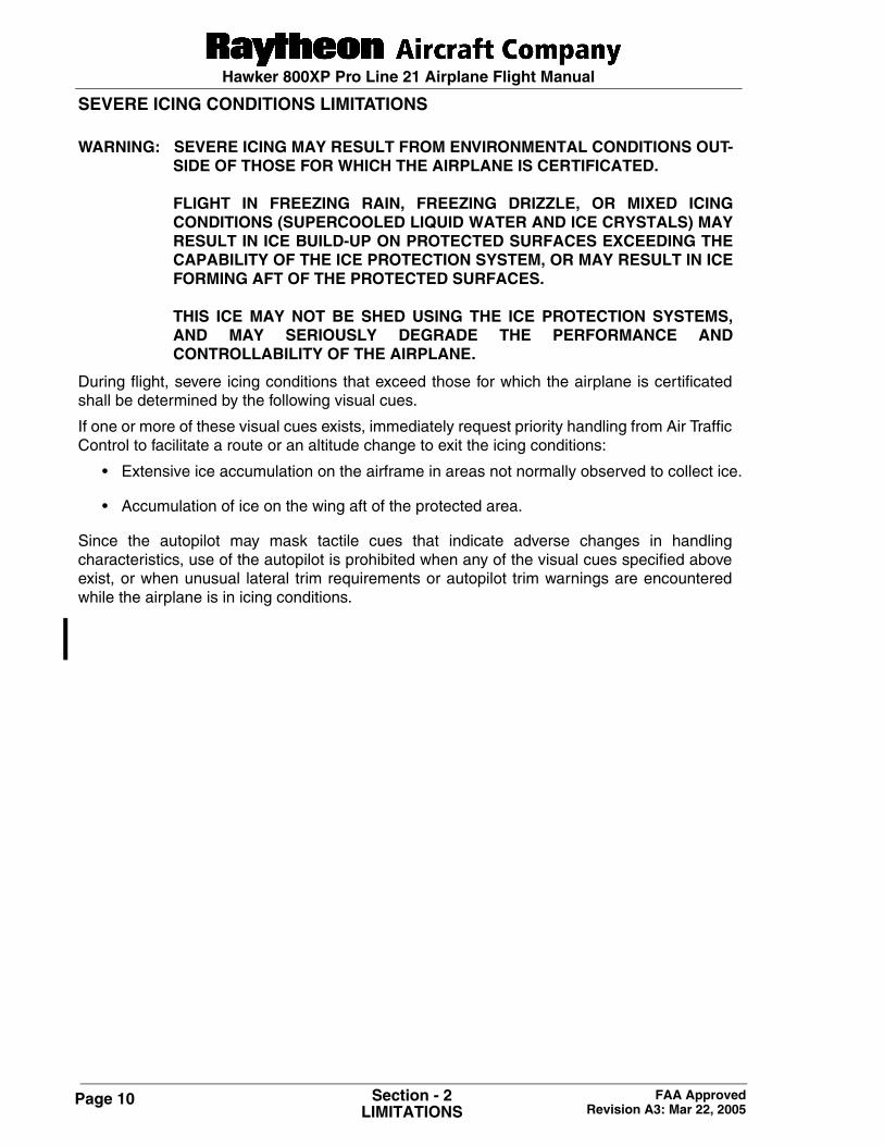
SEVERE ICING CONDITIONS LIMITATIONS
WARNING: SEVERE ICING MAY RESULT FROM ENVIRONMENTAL CONDITIONS OUT-SIDE OF THOSE FOR WHICH THE AIRPLANE IS CERTIFICATED.
FLIGHT IN FREEZING RAIN, FREEZING DRIZZLE, OR MIXED ICINGCONDITIONS (SUPERCOOLED LIQUID WATER AND ICE CRYSTALS) MAYRESULT IN ICE BUILD-UP ON PROTECTED SURFACES EXCEEDING THECAPABILITY OF THE ICE PROTECTION SYSTEM, OR MAY RESULT IN ICEFORMING AFT OF THE PROTECTED SURFACES.
THIS ICE MAY NOT BE SHED USING THE ICE PROTECTION SYSTEMS,AND MAY SERIOUSLY DEGRADE THE PERFORMANCE ANDCONTROLLABILITY OF THE AIRPLANE.
During flight, severe icing conditions that exceed those for which the airplane is certificatedshall be determined by the following visual cues.
If one or more of these visual cues exists, immediately request priority handling from Air TrafficControl to facilitate a route or an altitude change to exit the icing conditions:
• Extensive ice accumulation on the airframe in areas not normally observed to collect ice.
• Accumulation of ice on the wing aft of the protected area.
Since the autopilot may mask tactile cues that indicate adverse changes in handlingcharacteristics, use of the autopilot is prohibited when any of the visual cues specified aboveexist, or when unusual lateral trim requirements or autopilot trim warnings are encounteredwhile the airplane is in icing conditions.
Page 11Section - 2LIMITATIONS
FAA Approved Revision A3: Mar 22, 2005
Hawker 800XP Pro Line 21 Airplane Flight Manual
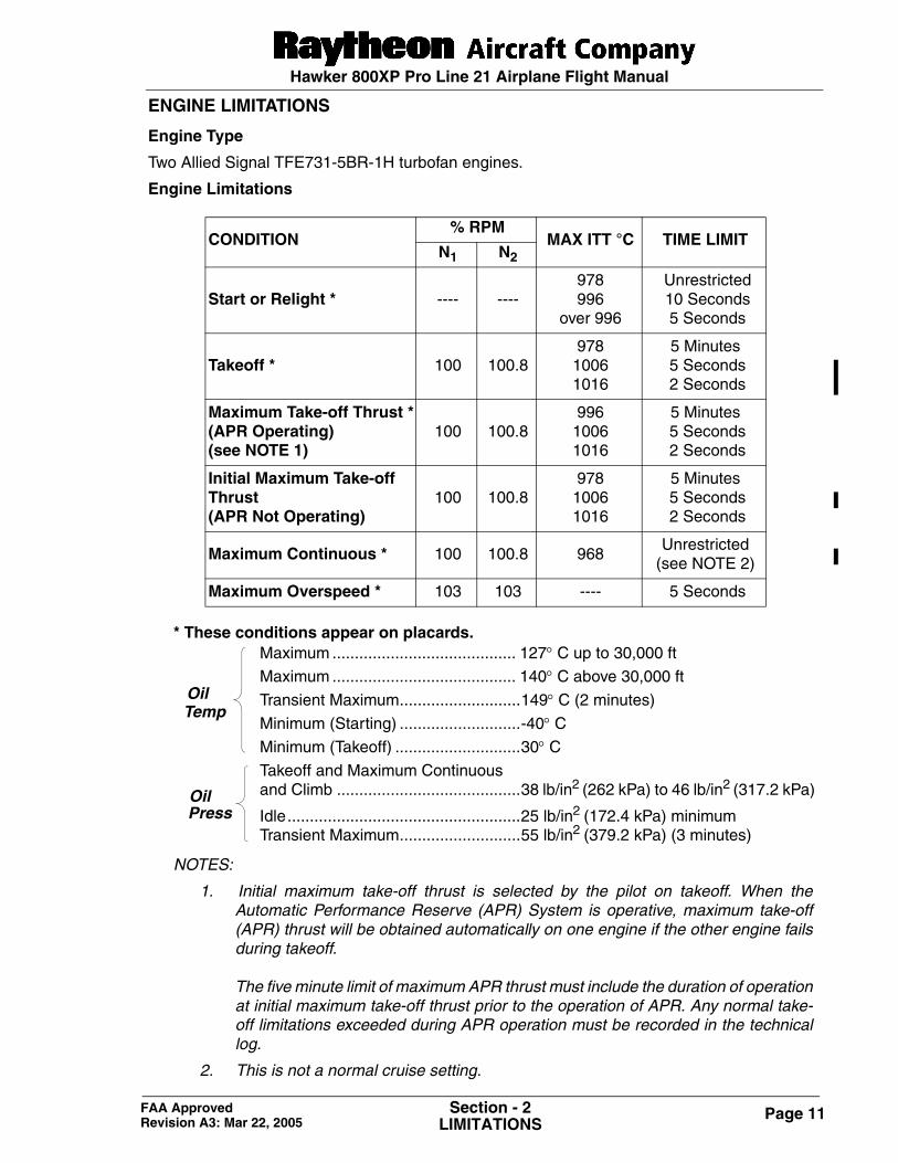
ENGINE LIMITATIONS
Engine Type
Two Allied Signal TFE731-5BR-1H turbofan engines.
Engine Limitations
* These conditions appear on placards.
NOTES:
1. Initial maximum take-off thrust is selected by the pilot on takeoff. When theAutomatic Performance Reserve (APR) System is operative, maximum take-off(APR) thrust will be obtained automatically on one engine if the other engine failsduring takeoff.
The five minute limit of maximum APR thrust must include the duration of operationat initial maximum take-off thrust prior to the operation of APR. Any normal take-off limitations exceeded during APR operation must be recorded in the technicallog.
2. This is not a normal cruise setting.
CONDITION% RPM
MAX ITT °C TIME LIMITN1 N2
Start or Relight * ---- ----978996
over 996
Unrestricted 10 Seconds 5 Seconds
Takeoff * 100 100.8978
10061016
5 Minutes 5 Seconds 2 Seconds
Maximum Take-off Thrust *(APR Operating) (see NOTE 1)
100 100.8996
10061016
5 Minutes 5 Seconds 2 Seconds
Initial Maximum Take-off Thrust(APR Not Operating)
100 100.8978
10061016
5 Minutes 5 Seconds 2 Seconds
Maximum Continuous * 100 100.8 968Unrestricted
(see NOTE 2)
Maximum Overspeed * 103 103 ---- 5 Seconds
Maximum ......................................... 127° C up to 30,000 ft
Maximum ......................................... 140° C above 30,000 ft
Transient Maximum...........................149° C (2 minutes)
Minimum (Starting) ...........................-40° CMinimum (Takeoff) ............................30° CTakeoff and Maximum Continuousand Climb .........................................38 lb/in2 (262 kPa) to 46 lb/in2 (317.2 kPa)
Idle....................................................25 lb/in2 (172.4 kPa) minimumTransient Maximum...........................55 lb/in2 (379.2 kPa) (3 minutes)
TempOil
PressOil
Page 12 Section - 2LIMITATIONS
FAA Approved Revision A3: Mar 22, 2005
Hawker 800XP Pro Line 21 Airplane Flight Manual
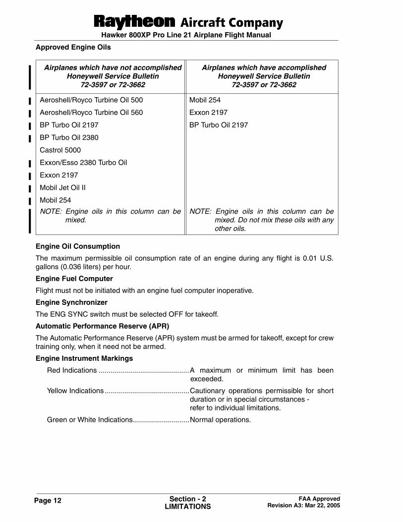
Approved Engine Oils
Engine Oil Consumption
The maximum permissible oil consumption rate of an engine during any flight is 0.01 U.S.gallons (0.036 liters) per hour.
Engine Fuel Computer
Flight must not be initiated with an engine fuel computer inoperative.
Engine Synchronizer
The ENG SYNC switch must be selected OFF for takeoff.
Automatic Performance Reserve (APR)
The Automatic Performance Reserve (APR) system must be armed for takeoff, except for crewtraining only, when it need not be armed.
Engine Instrument Markings
Red Indications .............................................A maximum or minimum limit has beenexceeded.
Yellow Indications ..........................................Cautionary operations permissible for shortduration or in special circumstances - refer to individual limitations.
Green or White Indications............................Normal operations.
Airplanes which have not accomplished Honeywell Service Bulletin
72-3597 or 72-3662
Airplanes which have accomplishedHoneywell Service Bulletin
72-3597 or 72-3662
Aeroshell/Royco Turbine Oil 500 Mobil 254
Aeroshell/Royco Turbine Oil 560 Exxon 2197
BP Turbo Oil 2197 BP Turbo Oil 2197
BP Turbo Oil 2380
Castrol 5000
Exxon/Esso 2380 Turbo Oil
Exxon 2197
Mobil Jet Oil II
Mobil 254
NOTE: Engine oils in this column can bemixed.
NOTE: Engine oils in this column can bemixed. Do not mix these oils with anyother oils.
Page 13Section - 2LIMITATIONS
FAA Approved Revision A3: Mar 22, 2005
Hawker 800XP Pro Line 21 Airplane Flight Manual
Thrust Reversers
• Deployment of either thrust reverser is restricted to ground operations only.
• The thrust reverse levers must not be selected until the airplane is on the ground.
• Engine starts with thrust reversers deployed are prohibited.
• Reverse thrust must not be used to taxi backwards.
• Thrust in excess of reverse idle must not be selected below speeds of 50 KIAS, except inan emergency.
• When operating on unpaved surfaces, reverse idle thrust must not be exceeded except inan emergency.
• If the thrust reverser system is known to be inoperative or unserviceable, it must bedisabled and locked in the forward thrust position.
Engine Ice Protection System
The ENG ANTICE switches may be selected ON at any engine speed. If engine anti-icing isrequired during takeoff, it is recommended that they should be turned ON prior to setting take-off power.
Engine inlet anti-icing should be used in flight continuously during expected icing conditions.
When icing conditions do not exist, the inlet anti-icing should not be used above 50° F (10° C)ambient conditions for more than 10 seconds.
FUEL LIMITATIONS
The following fuels and additives are approved for use with this engine installation.
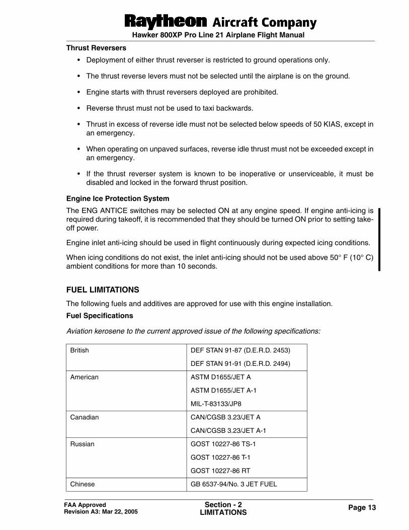
Fuel Specifications
Aviation kerosene to the current approved issue of the following specifications:
British DEF STAN 91-87 (D.E.R.D. 2453)
DEF STAN 91-91 (D.E.R.D. 2494)
American ASTM D1655/JET A
ASTM D1655/JET A-1
MIL-T-83133/JP8
Canadian CAN/CGSB 3.23/JET A
CAN/CGSB 3.23/JET A-1
Russian GOST 10227-86 TS-1
GOST 10227-86 T-1
GOST 10227-86 RT
Chinese GB 6537-94/No. 3 JET FUEL
Page 14 Section - 2LIMITATIONS
FAA Approved Revision A3: Mar 22, 2005
Hawker 800XP Pro Line 21 Airplane Flight Manual
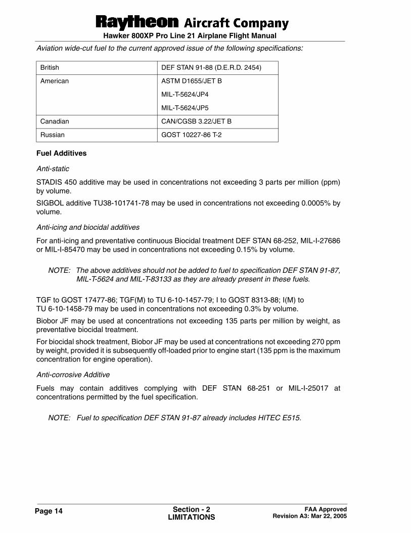
Aviation wide-cut fuel to the current approved issue of the following specifications:
Fuel Additives
Anti-static
STADIS 450 additive may be used in concentrations not exceeding 3 parts per million (ppm)by volume.
SIGBOL additive TU38-101741-78 may be used in concentrations not exceeding 0.0005% byvolume.
Anti-icing and biocidal additives
For anti-icing and preventative continuous Biocidal treatment DEF STAN 68-252, MIL-I-27686or MIL-I-85470 may be used in concentrations not exceeding 0.15% by volume.
NOTE: The above additives should not be added to fuel to specification DEF STAN 91-87,MIL-T-5624 and MIL-T-83133 as they are already present in these fuels.
TGF to GOST 17477-86; TGF(M) to TU 6-10-1457-79; I to GOST 8313-88; I(M) to TU 6-10-1458-79 may be used in concentrations not exceeding 0.3% by volume.
Biobor JF may be used at concentrations not exceeding 135 parts per million by weight, aspreventative biocidal treatment.
For biocidal shock treatment, Biobor JF may be used at concentrations not exceeding 270 ppmby weight, provided it is subsequently off-loaded prior to engine start (135 ppm is the maximumconcentration for engine operation).
Anti-corrosive Additive
Fuels may contain additives complying with DEF STAN 68-251 or MIL-I-25017 atconcentrations permitted by the fuel specification.
NOTE: Fuel to specification DEF STAN 91-87 already includes HITEC E515.
British DEF STAN 91-88 (D.E.R.D. 2454)
American ASTM D1655/JET B
MIL-T-5624/JP4
MIL-T-5624/JP5
Canadian CAN/CGSB 3.22/JET B
Russian GOST 10227-86 T-2
Hawker 800XP Pro Line 21 Airplane Flight Manual
Page 15Section - 2LIMITATIONS
FAA Approved Revision A1: Nov 13, 2002
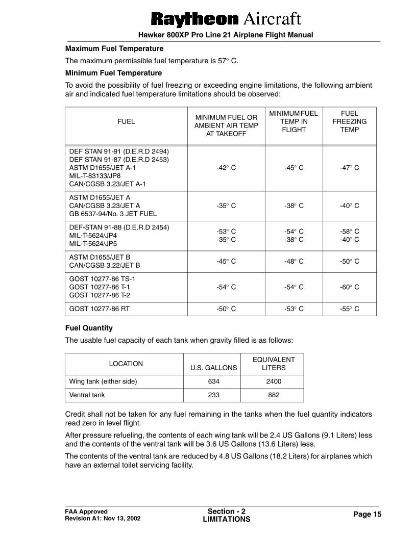
Maximum Fuel Temperature
The maximum permissible fuel temperature is 57° C.
Minimum Fuel Temperature
To avoid the possibility of fuel freezing or exceeding engine limitations, the following ambientair and indicated fuel temperature limitations should be observed:
Fuel Quantity
The usable fuel capacity of each tank when gravity filled is as follows:
Credit shall not be taken for any fuel remaining in the tanks when the fuel quantity indicatorsread zero in level flight.
After pressure refueling, the contents of each wing tank will be 2.4 US Gallons (9.1 Liters) lessand the contents of the ventral tank will be 3.6 US Gallons (13.6 Liters) less.
The contents of the ventral tank are reduced by 4.8 US Gallons (18.2 Liters) for airplanes whichhave an external toilet servicing facility.
FUELMINIMUM FUEL OR AMBIENT AIR TEMP
AT TAKEOFF
MINIMUM FUEL TEMP IN FLIGHT
FUEL FREEZING
TEMP
DEF STAN 91-91 (D.E.R.D 2494)DEF STAN 91-87 (D.E.R.D 2453)ASTM D1655/JET A-1MIL-T-83133/JP8CAN/CGSB 3.23/JET A-1
-42° C -45° C -47° C
ASTM D1655/JET ACAN/CGSB 3.23/JET AGB 6537-94/No. 3 JET FUEL
-35° C -38° C -40° C
DEF-STAN 91-88 (D.E.R.D 2454)MIL-T-5624/JP4MIL-T-5624/JP5
-53° C-35° C
-54° C-38° C
-58° C-40° C
ASTM D1655/JET BCAN/CGSB 3.22/JET B
-45° C -48° C -50° C
GOST 10277-86 TS-1GOST 10277-86 T-1GOST 10277-86 T-2
-54° C -54° C -60° C
GOST 10277-86 RT -50° C -53° C -55° C
LOCATION
U.S. GALLONSEQUIVALENT
LITERS
Wing tank (either side) 634 2400
Ventral tank 233 882
Hawker 800XP Pro Line 21 Airplane Flight Manual
Page 16 Section - 2LIMITATIONS
FAA Approved Revision A1: Nov 13, 2002
Fuel Loading
Fuel tanks may be replenished in any sequence provided that the appropriate refuelinginstructions are observed and that the following preflight fuel loading conditions are achieved:
1. Fuel contained in the wing tanks shall be equally disposed between the two wing tanks.
2. Fuel must not be carried in the ventral tank unless each main wing tank contains at least3450 lb (1565 kg) of fuel.
3. Before flights on which it is to be utilized, the ventral tank must be filled completely. For other flights it must be empty.
Pressure Refueling
Takeoff must not be initiated if the amber FUEL annunciator on the MWS panel and the amberREFUEL ON annunciator on the roof panel are illuminated.
Flight with the Refuel Power Switch ON is prohibited.
Fuel System Management
1. During flight, including takeoff and landing, the difference in fuel quantity between the twowing tanks must not exceed 500 lb (227 kg).
2. Fuel carried in the ventral fuel tank shall be transferred into the wing tanks when the fuel levelin the wing tanks has fallen to 3300 lb (1497 kg) per side.
3. Overweight landing procedure and inspection is required for any landing with fuel in theventral tank.
ELECTRICAL LIMITATIONS
Battery Limitations
Maximum battery charge on the main airplane batteries (B1 and B2) immediately beforetakeoff shall not be greater than 20 AMPS.
Generator Limitations
Maximum continuous engine generator load: 300 AMPS
NOTE: Transient excursions, up to a maximum of 400 AMPS, are permitted for a maximumof 2 minutes.
Main Engine Starter Duty Cycle
On the ground, the maximum permitted starter operating time is 30 seconds. After an abortedstart, a minimum of 1 minute cooling time must be allowed before making another attempt tostart. A further 1 minute is required before making a third attempt. The cycle may be repeatedafter a further period of 30 minutes.
Operation of Electrical Circuit Breakers
If, during flight, a systems failure is accompanied by a circuit breaker operation, no attemptmust be made to reset the circuit breaker unless specified in the appropriate Emergency orAbnormal procedure or, if deemed necessary for the continuation of safe flight, a circuit breakermay be reset once.
Hawker 800XP Pro Line 21 Airplane Flight Manual
Page 17Section - 2LIMITATIONS
FAA Approved Revision A1: Nov 13, 2002
AVIONICS LIMITATIONS
General
1. The following documents must be carried onboard the airplane at all times:
• Collins Pro Line 21 Avionics System for the Hawker 800XP Pilot’s Guide P/N 523-0780409, 1st Edition dated May 31, 2001 or later revision.
• Collins FMS-6000 Flight Management System for the Hawker 800XP Pilot’s Guide, P/N 523-0780705, 1st Edition dated April 17, 2001 or later revision.
• Mk V Enhanced Ground Proximity Warning System Pilot Guide, P/N 060-4241-0000, Rev D, dated March 2000 or later revision.
These publications contain the description and operation of the Collins Pro Line 21 avionics, theFMS-6000, TCAS II and EGPWS installations and must be available for use.
2. The pilot’s and copilot’s Air Data Computers must be operative for takeoff.
3. AHRS 1 and 2 must be operative for takeoff.
HF Radio
1. When the ADF is being used for approaches, the use of the HF radio is prohibited.
2. Fuel quantity indications are not to be used during HF radio transmissions.
Electronic Standby Instrument System (ESIS)
1. The red airspeed warning on the ESIS airspeed tape does not provide an associated auralwarning.
2. During operations solely with references to the ESIS, the standby VMO/MMO indication mustnot be exceeded, as the ESIS altitude and airspeed indications are not corrected for staticerror.
Flight Management System
1. IFR enroute and terminal navigation is prohibited unless the pilot verifies either the currencyof the database or the accuracy of each selected waypoint and navaid by reference to currentapproved data.
2. The FMS position must be checked for accuracy prior to use as a means of navigation andunder the following conditions:
• At or prior to arrival at each enroute waypoint during FMS navigation along approvedRNAV routes.
• Prior to requesting off-airway routing and at hourly intervals thereafter during FMSnavigation off approved RNAV routes.
• Prior to each compulsory reporting point during IFR operation when not under radarsurveillance control.
3. During periods of dead reckoning, the FMS shall not be used for navigation.
Hawker 800XP Pro Line 21 Airplane Flight Manual
Page 18 Section - 2LIMITATIONS
FAA Approved Revision A1: Nov 13, 2002
4. All FMS navigation operations are approved within the U.S. National Airspace System andlatitudes bounded by 60° North latitude and 60° South latitude at any longitude.
• Operation to 70° North latitude is acceptable East of 75° West longitude and West of 120°West longitude.
• Operation to 80° North latitude is acceptable East of 50° West longitude and West of 70°East longitude.
• Operation to 70° South latitude is acceptable except for the 45° between 120° East and165° East longitude.
• The WGS-84 coordinate reference datum in accordance with the criteria of AC 20-130A,AC 91-49, and AC 120-33 must be used. Satellite navigation data is based upon use ofonly the Global Positioning System (GPS) operated by the United States.
5. FMS-based Instrument approaches must be accomplished in accordance with approvedinstrument approach procedures that are retrieved from the FMS-6000 data base.
• Instrument approaches must be conducted in the approach mode and GPS integritymonitoring (RAIM) must be available at the Final Approach Fix.
• Accomplishment of ILS, LOC, LOC-BC, LDA and SDF approaches are not authorizedutilizing the FMS.
• When an alternate airport is required by the applicable operating rules, it must be servedby an approach based on other than GPS navigation, the airplane must have operationalequipment capable of using that navigation aid, and the required navigation aid must beoperational.
• FMS based approaches that are retrieved from the navigation database with an approachname of RNVxxx may be flown provided the VHF navigation receiver is tuned to thereference facility.
6. Provided the FMS is receiving adequate usable sensor inputs, it has been demonstratedcapable of and has been shown to meet the accuracy specifications of:
• VFR/IFR enroute RNAV operation in accordance with the criteria of AC 20-130A.
• GPS primary means of navigation in oceanic and remote airspace in accordance with AC20-130A, when used in conjunction with the Collins Fault Detection and Exclusionsoftware, dual Collins FMS-6000 Flight Management Systems and dual GPS-4000Areceivers or a single FMS-6000 Flight Management System and/or Collins GPS-4000Areceiver when operating on routes approved for single GPS navigation.
This does not constitute an operational approval.
NOTE: With single Flight Management System operation, cross reference must be madeto the Airplane Flight Manual for operating procedures and performance data.
Page 1 of 1 P/N 140-590032-0005TC12 (Issue 2)November 8, 2005
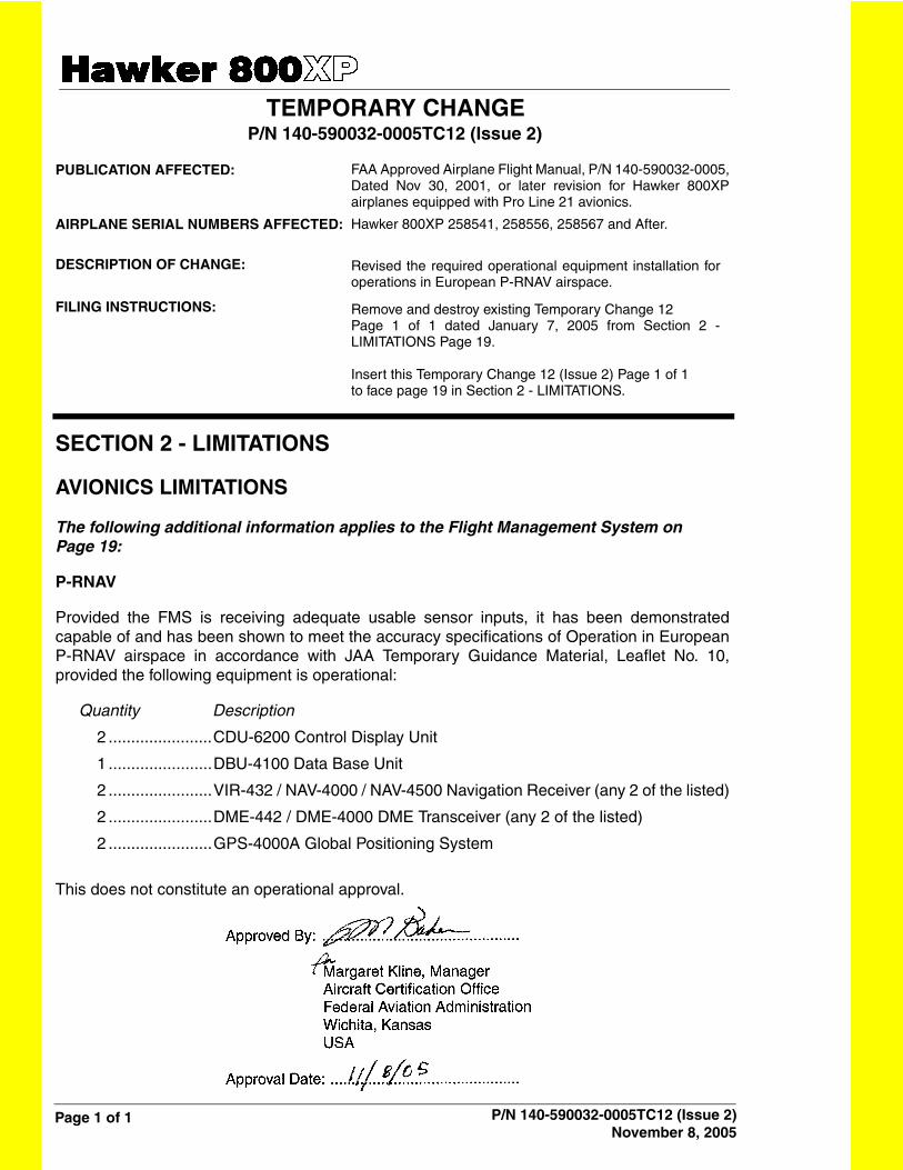
TEMPORARY CHANGE P/N 140-590032-0005TC12 (Issue 2)
PUBLICATION AFFECTED:
AIRPLANE SERIAL NUMBERS AFFECTED:
DESCRIPTION OF CHANGE:
FILING INSTRUCTIONS:
SECTION 2 - LIMITATIONS
AVIONICS LIMITATIONS
The following additional information applies to the Flight Management System on Page 19:
P-RNAV
Provided the FMS is receiving adequate usable sensor inputs, it has been demonstratedcapable of and has been shown to meet the accuracy specifications of Operation in EuropeanP-RNAV airspace in accordance with JAA Temporary Guidance Material, Leaflet No. 10,provided the following equipment is operational:
Quantity Description
2 .......................CDU-6200 Control Display Unit
1 .......................DBU-4100 Data Base Unit
2 .......................VIR-432 / NAV-4000 / NAV-4500 Navigation Receiver (any 2 of the listed)
2 .......................DME-442 / DME-4000 DME Transceiver (any 2 of the listed)
2 .......................GPS-4000A Global Positioning System
This does not constitute an operational approval.
FAA Approved Airplane Flight Manual, P/N 140-590032-0005,Dated Nov 30, 2001, or later revision for Hawker 800XPairplanes equipped with Pro Line 21 avionics.
Hawker 800XP 258541, 258556, 258567 and After.
Revised the required operational equipment installation foroperations in European P-RNAV airspace.
Remove and destroy existing Temporary Change 12 Page 1 of 1 dated January 7, 2005 from Section 2 -LIMITATIONS Page 19.
Insert this Temporary Change 12 (Issue 2) Page 1 of 1to face page 19 in Section 2 - LIMITATIONS.
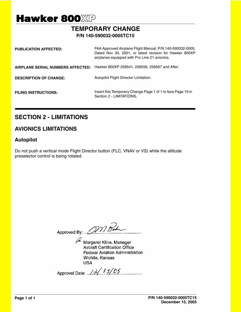
Page 1 of 1 P/N 140-590032-0005TC15December 15, 2005
TEMPORARY CHANGE P/N 140-590032-0005TC15
PUBLICATION AFFECTED:
AIRPLANE SERIAL NUMBERS AFFECTED:
DESCRIPTION OF CHANGE:
FILING INSTRUCTIONS:
SECTION 2 - LIMITATIONS
AVIONICS LIMITATIONS
Autopilot
Do not push a vertical mode Flight Director button (FLC, VNAV or VS) while the altitude preselector control is being rotated.
FAA Approved Airplane Flight Manual, P/N 140-590032-0005,Dated Nov 30, 2001, or latest revision for Hawker 800XPairplanes equipped with Pro Line 21 avionics.
Hawker 800XP 258541, 258556, 258567 and After.
Autopilot Flight Director Limitation.
Insert this Temporary Change Page 1 of 1 to face Page 19 in Section 2 - LIMITATIONS,
Hawker 800XP Pro Line 21 Airplane Flight Manual
Page 19Section - 2LIMITATIONS
FAA Approved Revision A1: Nov 13, 2002
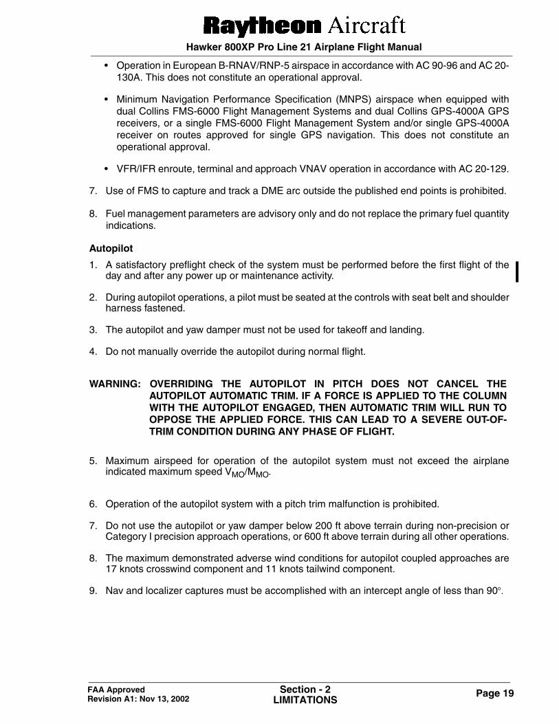
• Operation in European B-RNAV/RNP-5 airspace in accordance with AC 90-96 and AC 20-130A. This does not constitute an operational approval.
• Minimum Navigation Performance Specification (MNPS) airspace when equipped withdual Collins FMS-6000 Flight Management Systems and dual Collins GPS-4000A GPSreceivers, or a single FMS-6000 Flight Management System and/or single GPS-4000Areceiver on routes approved for single GPS navigation. This does not constitute anoperational approval.
• VFR/IFR enroute, terminal and approach VNAV operation in accordance with AC 20-129.
7. Use of FMS to capture and track a DME arc outside the published end points is prohibited.
8. Fuel management parameters are advisory only and do not replace the primary fuel quantityindications.
Autopilot
1. A satisfactory preflight check of the system must be performed before the first flight of theday and after any power up or maintenance activity.
2. During autopilot operations, a pilot must be seated at the controls with seat belt and shoulderharness fastened.
3. The autopilot and yaw damper must not be used for takeoff and landing.
4. Do not manually override the autopilot during normal flight.
WARNING: OVERRIDING THE AUTOPILOT IN PITCH DOES NOT CANCEL THEAUTOPILOT AUTOMATIC TRIM. IF A FORCE IS APPLIED TO THE COLUMNWITH THE AUTOPILOT ENGAGED, THEN AUTOMATIC TRIM WILL RUN TOOPPOSE THE APPLIED FORCE. THIS CAN LEAD TO A SEVERE OUT-OF-TRIM CONDITION DURING ANY PHASE OF FLIGHT.
5. Maximum airspeed for operation of the autopilot system must not exceed the airplaneindicated maximum speed VMO/MMO.
6. Operation of the autopilot system with a pitch trim malfunction is prohibited.
7. Do not use the autopilot or yaw damper below 200 ft above terrain during non-precision orCategory I precision approach operations, or 600 ft above terrain during all other operations.
8. The maximum demonstrated adverse wind conditions for autopilot coupled approaches are17 knots crosswind component and 11 knots tailwind component.
9. Nav and localizer captures must be accomplished with an intercept angle of less than 90°.
Hawker 800XP Pro Line 21 Airplane Flight Manual
Page 20 Section - 2LIMITATIONS
FAA Approved Revision A1: Nov 13, 2002
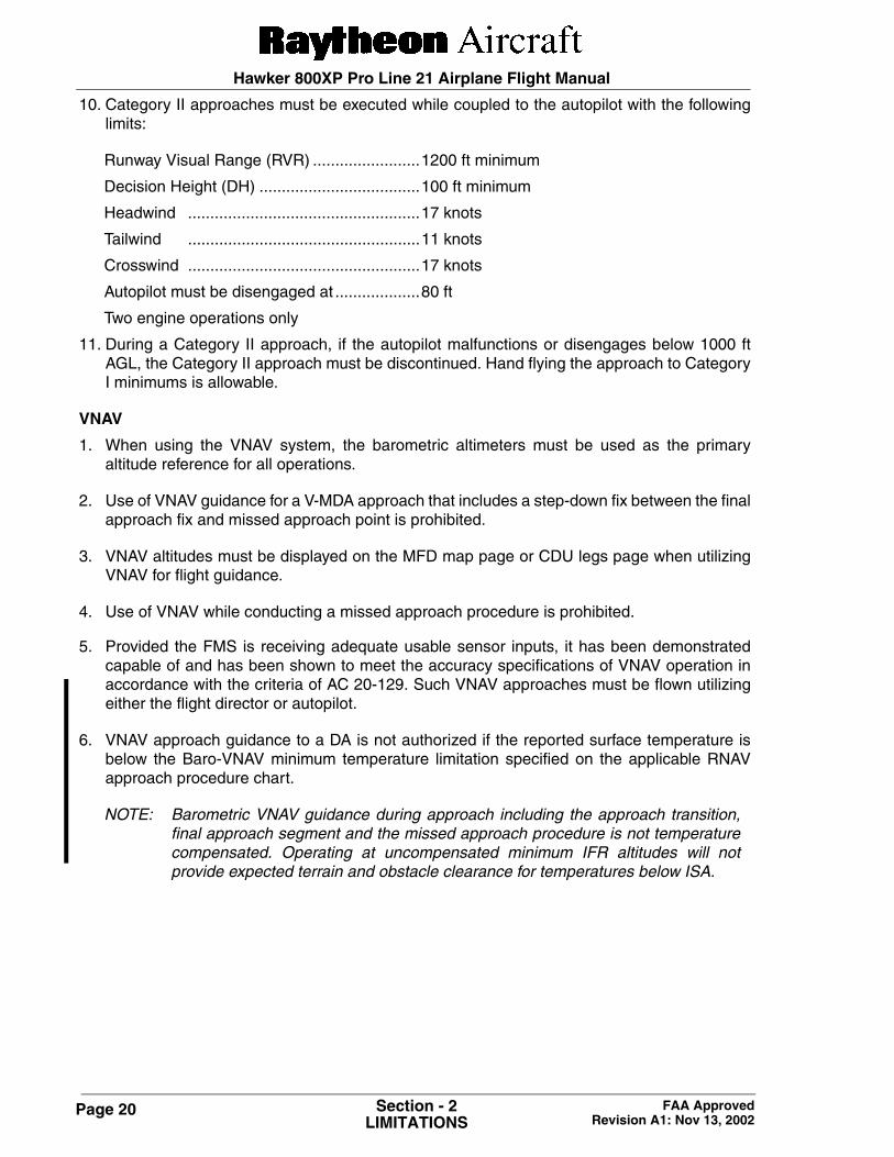
10. Category II approaches must be executed while coupled to the autopilot with the followinglimits:
Runway Visual Range (RVR) ........................1200 ft minimum
Decision Height (DH) ....................................100 ft minimum
Headwind ....................................................17 knots
Tailwind ....................................................11 knots
Crosswind ....................................................17 knots
Autopilot must be disengaged at ...................80 ft
Two engine operations only
11. During a Category II approach, if the autopilot malfunctions or disengages below 1000 ftAGL, the Category II approach must be discontinued. Hand flying the approach to CategoryI minimums is allowable.
VNAV
1. When using the VNAV system, the barometric altimeters must be used as the primaryaltitude reference for all operations.
2. Use of VNAV guidance for a V-MDA approach that includes a step-down fix between the finalapproach fix and missed approach point is prohibited.
3. VNAV altitudes must be displayed on the MFD map page or CDU legs page when utilizingVNAV for flight guidance.
4. Use of VNAV while conducting a missed approach procedure is prohibited.
5. Provided the FMS is receiving adequate usable sensor inputs, it has been demonstratedcapable of and has been shown to meet the accuracy specifications of VNAV operation inaccordance with the criteria of AC 20-129. Such VNAV approaches must be flown utilizingeither the flight director or autopilot.
6. VNAV approach guidance to a DA is not authorized if the reported surface temperature isbelow the Baro-VNAV minimum temperature limitation specified on the applicable RNAVapproach procedure chart.
NOTE: Barometric VNAV guidance during approach including the approach transition,final approach segment and the missed approach procedure is not temperaturecompensated. Operating at uncompensated minimum IFR altitudes will notprovide expected terrain and obstacle clearance for temperatures below ISA.
Page 21Section - 2LIMITATIONS
FAA Approved Revision A3: Mar 22, 2005
Hawker 800XP Pro Line 21 Airplane Flight Manual
EGPWS
1. Navigation must not be predicated upon the use of the TAD. The Terrain Display is intendedto serve as a situational awareness tool only and may not provide the accuracy and/or fidelityon which to solely base terrain avoidance maneuvering.
2. Pilots are authorized to deviate from their current air traffic control (ATC) clearance to theextent necessary to comply with an EGPWS warning.
3. In order to avoid giving unwanted alerts, the Terrain Awareness alerting must be inhibited byselecting the TERR INHIB switchlight when within 15 nautical miles of takeoff, approach orlanding at an airport not contained in the EGPWS Airport Database. Refer to Honeywelldocument 060-4326-000 for airports contained in the installed EGPWS Terrain Database.
4. When the FMS is operating in the DR mode, the Terrain Awareness alerting must be inhibitedby selecting the TERR INHIB switchlight.
NOTE: The terrain database, displays and alerting algorithms currently account for limitedcataloged human-made obstructions in North America and Europe. If obstacledata is not in the database for a particular obstacle, the Obstacle Awarenessalerting is not available for that obstacle.
TCAS II
Pilots are authorized to deviate from their current ATC clearance to the extent necessary tocomply with a TCAS resolution advisory.
If ATC requires the transponder altitude reporting to be disabled, TCAS II must be turned off.
Page 22 Section - 2LIMITATIONS
FAA Approved Revision A3: Mar 22, 2005
Hawker 800XP Pro Line 21 Airplane Flight Manual
AIRSPEED LIMITATIONS
Maximum Operating Speed
VMO ................................................................280 KIAS (Ventral fuel tank not empty, Flaps 0°)
VMO ................................................................335 KIAS (Ventral fuel tank empty, Flaps 0°)Sea Level to 12,000 ft, reducing by 1 kt per680 ft to 310 KIAS at 29,000 ft.
Maximum Operating Mach Number
MMO...............................................................0.80 IMN
MMO...............................................................0.73 IMN with Mach Trim System Fail/Inoperative and Autopilot disengaged.
NOTE: The maximum operating speeds and operating Mach numbers as given aboveshall not be deliberately exceeded in any regime of flight (climb, cruise ordescent) except for the purpose of pilot training or routine test flights inaccordance with Section 5, Sub-section 2 of the Pilot’s Operating Manual (POM).
If the limits are inadvertently exceeded, speed shall be reduced to or below thelimiting values as quickly as possible.
Maneuvering Speed
VA ..................................................................196 KIAS
NOTE: Maneuvering speed is the speed below which full application of aerodynamiccontrols will not result in excessive airplane loads. Maneuvers involving anglesof attack near the stall should be confined to speeds below VA.
Avoid rapid and large alternating control inputs, especially in combination withlarge changes in pitch, roll or yaw (e.g. large slip angles) as they may result instructural failures at any speed, including below VA.
Wing Flaps Extended/Operating Speed
VFE/VFO.........................................................220 KIAS (Flaps 15°)175 KIAS (Flaps 25°)165 KIAS (Flaps 45°)
Procedural Use of Flaps 15° for Descent and Holding
The maximum airspeed for procedural use of flaps 15° for descent and holding is 220 KIAS.
The maximum altitude for use is 15,000 ft. Such use of wing flaps is not permitted in icingconditions.
Hawker 800XP Pro Line 21 Airplane Flight Manual
Page 23Section - 2LIMITATIONS
FAA Approved Revision A1: Nov 13, 2002
Air Brakes
Air Brakes (Flaps 0° Only) .......................... No Limit
Landing Gear Extended/Operating Speed
VLE/VLO ........................................................ 220 KIAS
Bird Strike Speed
Under normal conditions the maximum permissible airspeed to meet bird strike requirementsis 280 KIAS up to 8000 ft.
Following an airplane ground soak at temperatures below -10° C, the windscreen heat shouldbe operative and selected ON for a minimum of 5 minutes prior to takeoff in ambienttemperatures of below -10° C and for a minimum of 15 minutes prior to takeoff when ambienttemperatures are below -20° C.
If the minimum times for windscreen heat operation have not been achieved or in the case of windscreen heat failure followed by flight in ambient temperature below -10° C, the maximum permissible airspeed is 257 KIAS up to 8000 ft.
Hawker 800XP Pro Line 21 Airplane Flight Manual
Page 24 Section - 2LIMITATIONS
FAA Approved Original Issue: Nov 30, 2001
Intentionally left blank
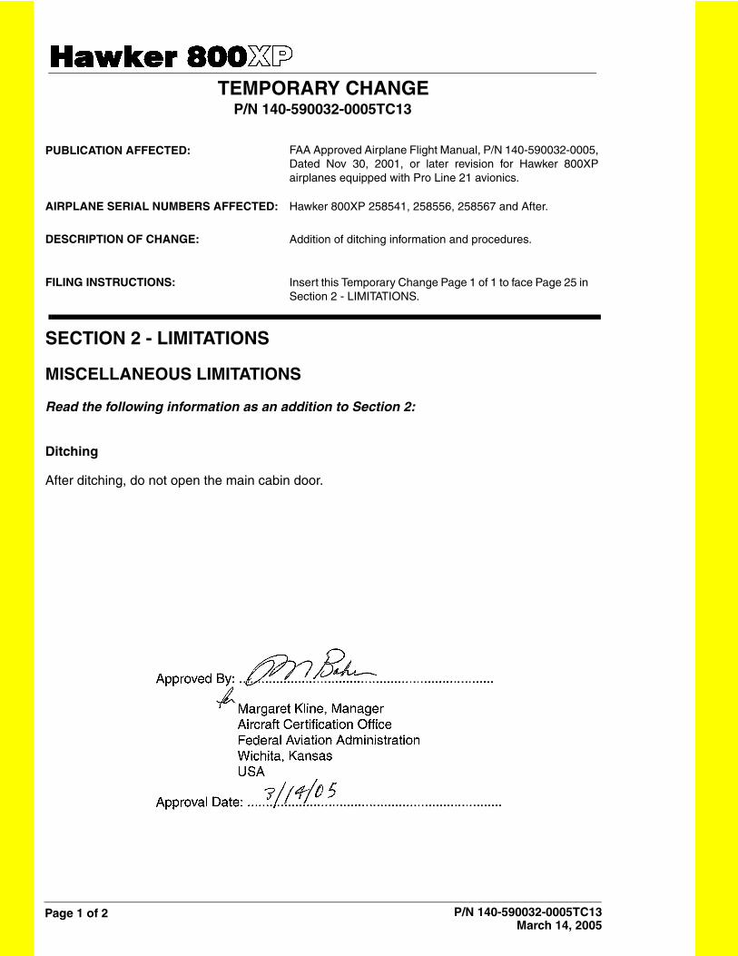
Page 1 of 2 P/N 140-590032-0005TC13March 14, 2005
TEMPORARY CHANGE P/N 140-590032-0005TC13
PUBLICATION AFFECTED:
AIRPLANE SERIAL NUMBERS AFFECTED:
DESCRIPTION OF CHANGE:
FILING INSTRUCTIONS:
SECTION 2 - LIMITATIONS
MISCELLANEOUS LIMITATIONS
Read the following information as an addition to Section 2:
Ditching
After ditching, do not open the main cabin door.
FAA Approved Airplane Flight Manual, P/N 140-590032-0005,Dated Nov 30, 2001, or later revision for Hawker 800XPairplanes equipped with Pro Line 21 avionics.
Hawker 800XP 258541, 258556, 258567 and After.
Addition of ditching information and procedures.
Insert this Temporary Change Page 1 of 1 to face Page 25 in Section 2 - LIMITATIONS.
Hawker 800XP Pro Line 21 Airplane Flight Manual
Page 25Section - 2LIMITATIONS
FAA Approved Revision A1: Nov 13, 2002
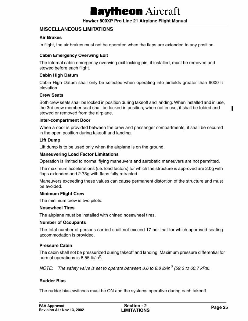
MISCELLANEOUS LIMITATIONS
Air Brakes
In flight, the air brakes must not be operated when the flaps are extended to any position.
Cabin Emergency Overwing Exit
The internal cabin emergency overwing exit locking pin, if installed, must be removed and stowed before each flight.
Cabin High Datum
Cabin High Datum shall only be selected when operating into airfields greater than 9000 ftelevation.
Crew Seats
Both crew seats shall be locked in position during takeoff and landing. When installed and in use, the 3rd crew member seat shall be locked in position; when not in use, it shall be folded and stowed or removed from the airplane.
Inter-compartment Door
When a door is provided between the crew and passenger compartments, it shall be securedin the open position during takeoff and landing.
Lift Dump
Lift dump is to be used only when the airplane is on the ground.
Maneuvering Load Factor Limitations
Operation is limited to normal flying maneuvers and aerobatic maneuvers are not permitted.
The maximum accelerations (i.e. load factors) for which the structure is approved are 2.0g withflaps extended and 2.73g with flaps fully retracted.
Maneuvers exceeding these values can cause permanent distortion of the structure and mustbe avoided.
Minimum Flight Crew
The minimum crew is two pilots.
Nosewheel Tires
The airplane must be installed with chined nosewheel tires.
Number of Occupants
The total number of persons carried shall not exceed 17 nor that for which approved seatingaccommodation is provided.
Pressure Cabin
The cabin shall not be pressurized during takeoff and landing. Maximum pressure differential for normal operations is 8.55 lb/in2.
NOTE: The safety valve is set to operate between 8.6 to 8.8 lb/in2 (59.3 to 60.7 kPa).
Rudder Bias
The rudder bias switches must be ON and the systems operative during each takeoff.
Hawker 800XP Pro Line 21 Airplane Flight Manual
Page 26 Section - 2LIMITATIONS
FAA Approved Revision A1: Nov 13, 2002
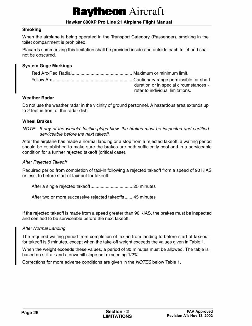
Smoking
When the airplane is being operated in the Transport Category (Passenger), smoking in thetoilet compartment is prohibited.
Placards summarizing this limitation shall be provided inside and outside each toilet and shallnot be obscured.
System Gage Markings
Red Arc/Red Radial................................................ Maximum or minimum limit.
Yellow Arc ............................................................... Cautionary range permissible for shortduration or in special circumstances - refer to individual limitations.
Weather Radar
Do not use the weather radar in the vicinity of ground personnel. A hazardous area extends upto 2 feet in front of the radar dish.
Wheel Brakes
NOTE: If any of the wheels’ fusible plugs blow, the brakes must be inspected and certifiedserviceable before the next takeoff.
After the airplane has made a normal landing or a stop from a rejected takeoff, a waiting periodshould be established to make sure the brakes are both sufficiently cool and in a serviceablecondition for a further rejected takeoff (critical case).
After Rejected Takeoff
Required period from completion of taxi-in following a rejected takeoff from a speed of 90 KIASor less, to before start of taxi-out for takeoff.
After a single rejected takeoff ..................................25 minutes
After two or more successive rejected takeoffs .......45 minutes
If the rejected takeoff is made from a speed greater than 90 KIAS, the brakes must be inspectedand certified to be serviceable before the next takeoff.
After Normal Landing
The required waiting period from completion of taxi-in from landing to before start of taxi-outfor takeoff is 5 minutes, except when the take-off weight exceeds the values given in Table 1.
When the weight exceeds these values, a period of 30 minutes must be allowed. The table isbased on still air and a downhill slope not exceeding 1/2%.
Corrections for more adverse conditions are given in the NOTES below Table 1.
Hawker 800XP Pro Line 21 Airplane Flight Manual
Page 27Section - 2LIMITATIONS
FAA Approved Revision A1: Nov 13, 2002
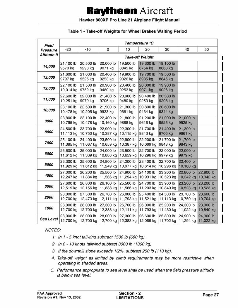
Table 1 - Take-off Weights for Wheel Brakes Waiting Period
NOTES:
1. In 1 - 5 knot tailwind subtract 1500 lb (680 kg).
2. In 6 - 10 knots tailwind subtract 3000 lb (1360 kg).
3. If the downhill slope exceeds 1/2%, subtract 250 lb (113 kg).
4. Take-off weight as limited by climb requirements may be more restrictive whenoperating in shaded areas.
5. Performance appropriate to sea level shall be used when the field pressure altitudeis below sea level.
FieldPressureAltitude ft
Temperature °C
-20 -10 0 10 20 30 40 50
Take-off Weight
14,00021,100 lb9570 kg
20,500 lb9298 kg
20,000 lb9071 kg
19,500 lb8845 kg
19,300 lb8754 kg
19,100 lb8663 kg
13,00021,600 lb9797 kg
21,000 lb9525 kg
20,400 lb9253 kg
19,900 lb9026 kg
19,700 lb8935 kg
19,500 lb8845 kg
12,00022,100 lb10,014 kg
21,500 lb9752 kg
20,900 lb9480 kg
20,400 lb9253 kg
20,000 lb9071 kg
19,900 lb9026 kg
11,00022,600 lb10,251 kg
22,000 lb9979 kg
21,400 lb9706 kg
20,900 lb9480 kg
20,400 lb9253 kg
20,300 lb9208 kg
10,00023,100 lb10,478 kg
22,500 lb10,205 kg
21,900 lb9933 kg
21,300 lb9661 kg
20,800 lb9434 kg
20,600 lb9344 kg
900023,800 lb10,795 kg
23,100 lb10,478 kg
22,400 lb10,160 kg
21,800 lb9888 kg
21,200 lb9616 kg
21,000 lb9525 kg
21,000 lb9525 kg
800024,500 lb11,113 kg
23,700 lb10,750 kg
22,900 lb10,387 kg
22,300 lb10,115 kg
21,700 lb9843 kg
21,400 lb9706 kg
21,300 lb9661 kg
700025,100 lb11,385 kg
24,400 lb11,067 kg
23,500 lb10,659 kg
22,900 lb10,387 kg
22,200 lb10,069 kg
21,700 lb9843 kg
21,700 lb9843 kg
600025,600 lb11,612 kg
25,000 lb11,339 kg
24,000 lb10,886 kg
23,500 lb10,659 kg
22,700 lb10,296 kg
22,000 lb9979 kg
22,000 lb9979 kg
500026,300 lb11,929 kg
25,600 lb11,612 kg
24,800 lb11,249 kg
24,200 lb10,977 kg
23,400 lb10,614 kg
22,700 lb10,296 kg
22,400 lb10,160 kg
400027,000 lb12,247 kg
26,200 lb11,884 kg
25,500 lb11,566 kg
24,900 lb11,294 kg
24,100 lb10,931 kg
23,200 lb10,523 kg
22,800 lb10,342 kg
22,800 lb10,342 kg
300027,600 lb12,519 kg
26,800 lb12,156 kg
26,100 lb11,838 kg
25,500 lb11,566 kg
24,700 lb11,203 kg
23,900 lb10,840 kg
23,200 lb10,523 kg
23,200 lb10,523 kg
200028,000 lb12,700 kg
27,500 lb12,473 kg
26,700 lb12,111 kg
26,000 lb11,793 kg
25,400 lb11,521 kg
24,500 lb11,113 kg
23,700 lb10,750 kg
23,600 lb10,704 kg
100028,000 lb12,700 kg
28,000 lb12,700 kg
27,300 lb12,383 kg
26,700 lb12,111 kg
26,000 lb11,793 kg
25,200 lb11,430 kg
24,300 lb11,022 kg
23,900 lb10,840 kg
Sea Level28,000 lb12,700 kg
28,000 lb12,700 kg
28,000 lb12,700 kg
27,300 lb12,383 kg
26,600 lb12,065 kg
25,800 lb11,702 kg
24,900 lb11,294 kg
24,300 lb11,022 kg