Embed Size (px)
Citation preview
HAULAGE ALTERNATIVES CASE STUDY FOR BOTTOM DUMP TRAILERS
LeRoy G. Hagenbuch, P.E. PHILIPPI‐HAGENBUCH, INC. 7424 WEST PLANK ROAD
PEORIA, ILLINOIS 61604‐5295 +1 (309) 697‐9200
www.philsystems.com
March 16, 1995
TABLE OF CONTENTS I STATEMENT OF PURPOSE II BACKGROUND ON SAND & GRAVEL PLANT III BACKGROUND OF THIS PAPER IV HAULAGE METHOD ANALYSIS V THE IMPORTANCE OF JOB MATCHING IN THE EQUIPMENT SELECTION PROCESS VI GENERAL STATEMENT OF EQUIPMENT REQUIREMENTS VII SPECIFIC BOTTOM DUMP HAULER OPERATING CRITERIA VIII BOTTOM DUMP HAULER SIZING CRITERIA IX TRAILER COMPONENTS AND CONSIDERATIONS THEREOF: A. OVERALL TRAILER STRUCTURE B. TURNSTOP C. HITCH D. TRAILER BODY TO TRAILER HITCH TRANSITION STRUCTURE E. TRAILER BODY F. DOORS G. DOOR ACTUATION
H. TRAILER BODY TO TRAILER REAR AXLE TRANSITION STRUCTURE I. TRAILER AXLE J. TRAILER AXLE SUSPENSION K. TRAILER BRAKES L. STEEL
X ANALYSIS OF NUMBER OF HAULAGE UNITS NEEDED XI BOTTOM DUMP HAULER PRODUCT DESCRIPTION XII SAMPLE BOTTOM DUMP TRAILER SPECIFICATION APPENDIX
www.philsystems.com 2
I. STATEMENT OF PURPOSE
The purpose of this presentation is to analyze Sand & Gravel Plant’s sand and gravel haulage operation by quantifying the needs of their haulage operation and analyzing various ways to meet these needs. The results of this analysis should enable individuals to understand the Sand & Gravel Plant’s haulage operation needs, determine appropriate solutions to these needs, and make recommendations as to the most appropriate equipment purchase necessary for improving the overall efficiency and productivity of the Sand & Gravel Plant haulage operation.
www.philsystems.com 3
II. BACKGROUND ON THE SAND & GRAVEL PLANT
The Sand & Gravel Plant is located on the Winding River just downstream from Bigtown, NJ. The Sand & Gravel Plant mines a sand and gravel deposit with mined material hauled to a processing plant which is permanently located on barges. The mined material is processed through this plant going through a washing and screening process to produce a finished product which is then shipped by barge down the Winding River to the port for trans‐shipment to other Sand & Gravel facilities. The Sand & Gravel Plant is unique in that no truck shipments take place from this plant — all material is shipped via water. Currently, the Sand & Gravel Plant is using four (4) Euclid B‐63 bottom dumps and one (1) Cat 630E bottom dump. The deposit being mined has anywhere from 25‐50 feet of dirt/overburden which is stripped off in 120 foot‐wide cuts. As the overburden is stripped off, the current bottom dump haulers drive over the top of the stripped‐off sand and gravel deposit. These bottom dump haulers are currently loaded with a dragline which loads these trucks in five to six passes. This plant has a Hitachi 7.7 cubic yard backhoe on order and it is planned that this backhoe will, when put into service, be the primary loading tool with the dragline that is currently the primary loading tool becoming a backup piece of loading equipment. The processing wash/screening plant which is a rebuilt plant just being commissioned is designed to produce finished product at the rate of 1000 tons per hour with a requirement to haul 1100 tons per hour to the plant, there being a 10% feed reduction between plant feed material and finished product out of the plant. The current haul length is 3.1 to 3.2 miles one way. The hauls at the Sand & Gravel Plant are currently anticipated not to exceed three (3) miles in length and, in fact, as the deposit that is currently being worked is mined out, the haul will go to about one (1) mile one way, and as this deposit is mined the haul would then go to two (2) miles one‐way haul. The water table is 10‐15 feet below the top of the sand and gravel deposit with these deposits extending down (it would appear 10‐15 feet, 15‐20 feet below the top of the water table) so that the deposits are then dug from below the water table. The ground in the actual working pit, i.e., the top of the sand and gravel deposits, has a fairly good footing though at times the rolling resistance can be fairly high, 5‐6 percent +/‐. However, as soon as a roadway gets packed down over the top of the sand and gravel deposits, rolling resistance in the actual haulage area goes right down to 2‐3 percent. So the periods when rolling resistance could be 5‐6 percent are very, very limited, if at all. The gradient out of the pit is very gradual, probably no more than 2‐3 percent, and the actual haul roads, once one gets out of the pits, are level, hard and smooth (less than a 2 percent rolling resistance).
www.philsystems.com 4
At the processing wash/screening plant a bottom dump hauler hopper is currently under construction. The top of this hopper will be somewhere in the area of 25‐30 feet above grade. However, here again, the ramp up to this hopper is very gradual with the gradient somewhere in the area of 2‐3 percent up to the hopper. The material being mined at the Sand & Gravel Plant weighs somewhere between 2750 pounds per cubic yard and 3300 pounds per cubic yard with the predominant weight being in the 3300 pound per cubic yard area. The angle of repose of the mined material is fairly steep so that the sidewalls of any hauler must also be fairly steep in keeping with the sidewall slope of the current bottom dump haulers.
www.philsystems.com 5
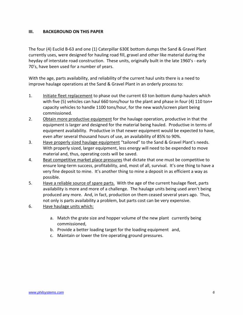
III. BACKGROUND ON THIS PAPER
The four (4) Euclid B‐63 and one (1) Caterpillar 630E bottom dumps the Sand & Gravel Plant currently uses, were designed for hauling road fill, gravel and other like material during the heyday of interstate road construction. These units, originally built in the late 1960’s ‐ early 70’s, have been used for a number of years. With the age, parts availability, and reliability of the current haul units there is a need to improve haulage operations at the Sand & Gravel Plant in an orderly process to: 1. Initiate fleet replacement to phase out the current 63 ton bottom dump haulers which
with five (5) vehicles can haul 660 tons/hour to the plant and phase in four (4) 110 ton+ capacity vehicles to handle 1100 tons/hour, for the new wash/screen plant being commissioned.
2. Obtain more productive equipment for the haulage operation, productive in that the equipment is larger and designed for the material being hauled. Productive in terms of equipment availability. Productive in that newer equipment would be expected to have, even after several thousand hours of use, an availability of 85% to 90%.
3. Have properly sized haulage equipment “tailored” to the Sand & Gravel Plant’s needs. With properly sized, larger equipment, less energy will need to be expended to move material and, thus, operating costs will be saved.
4. Beat competitive market place pressures that dictate that one must be competitive to ensure long‐term success, profitability, and, most of all, survival. It’s one thing to have a very fine deposit to mine. It’s another thing to mine a deposit in as efficient a way as possible.
5. Have a reliable source of spare parts. With the age of the current haulage fleet, parts availability is more and more of a challenge. The haulage units being used aren’t being produced any more. And, in fact, production on them ceased several years ago. Thus, not only is parts availability a problem, but parts cost can be very expensive.
6. Have haulage units which:
a. Match the grate size and hopper volume of the new plant currently being commissioned,
b. Provide a better loading target for the loading equipment and, c. Maintain or lower the tire operating ground pressures.
www.philsystems.com 6
IV. HAULAGE METHOD ANALYSIS
HAULAGE STYLE No study of the Sand & Gravel Plant haulage requirements would be complete without going back to square one and looking at distinct haulage style alternatives available. Currently, the Sand & Gravel Plant uses all bottom dump haulers for hauling sand and gravel. For any haulage equipment recommendation to be valid, it first is incumbent in the analysis to look at whether bottom dump trailers are the best alternative for the Sand & Gravel Plant haulage operation. In a broad sense, haulage such as what the Sand & Gravel Plant is doing is done with either: 1) A rear dump truck or, 2) A tractor‐trailer unit. With a tractor‐trailer unit being either a rear dump trailer or a
bottom dump trailer that dumps in a clam shell mode into a hopper or a trailer that dumps in a full‐trailer width dumping mode for spreading of material being dumped. With full‐width trailer dumping being performed by clam shell doors that operate transverse to the trailer or sliding doors such as what are often found on elevating and self‐loading dirt scrapers.
See flow chart that follows.
www.philsystems.com 7
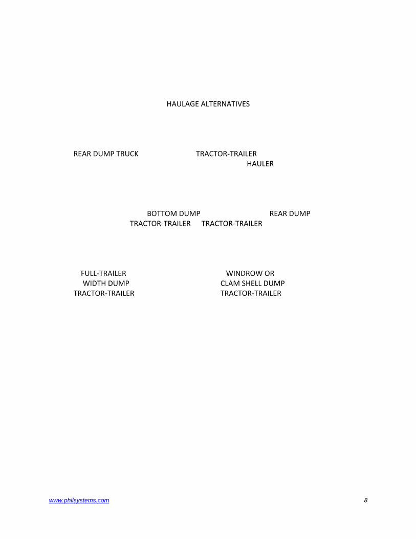
HAULAGE ALTERNATIVES
REAR DUMP TRUCK TRACTOR‐TRAILER HAULER BOTTOM DUMP REAR DUMP TRACTOR‐TRAILER TRACTOR‐TRAILER FULL‐TRAILER WINDROW OR WIDTH DUMP CLAM SHELL DUMP TRACTOR‐TRAILER TRACTOR‐TRAILER
www.philsystems.com 8
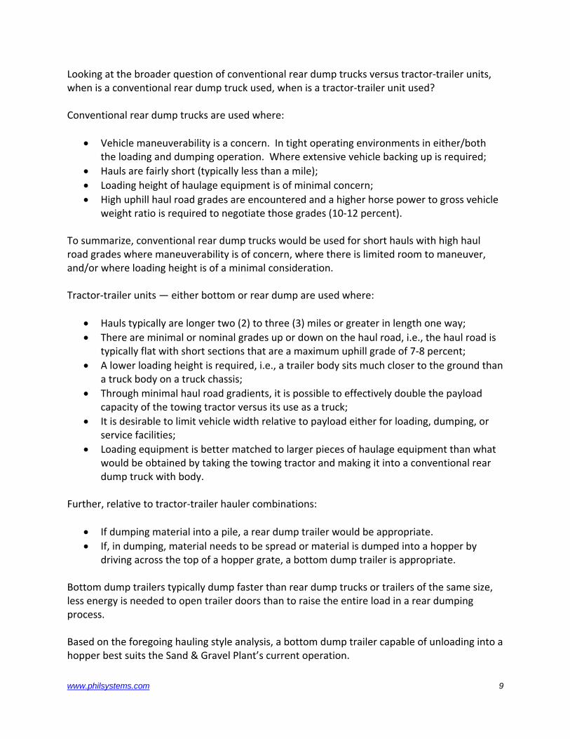
Looking at the broader question of conventional rear dump trucks versus tractor‐trailer units, when is a conventional rear dump truck used, when is a tractor‐trailer unit used? Conventional rear dump trucks are used where:
• Vehicle maneuverability is a concern. In tight operating environments in either/both the loading and dumping operation. Where extensive vehicle backing up is required;
• Hauls are fairly short (typically less than a mile); • Loading height of haulage equipment is of minimal concern; • High uphill haul road grades are encountered and a higher horse power to gross vehicle
weight ratio is required to negotiate those grades (10‐12 percent). To summarize, conventional rear dump trucks would be used for short hauls with high haul road grades where maneuverability is of concern, where there is limited room to maneuver, and/or where loading height is of a minimal consideration. Tractor‐trailer units — either bottom or rear dump are used where:
• Hauls typically are longer two (2) to three (3) miles or greater in length one way; • There are minimal or nominal grades up or down on the haul road, i.e., the haul road is
typically flat with short sections that are a maximum uphill grade of 7‐8 percent; • A lower loading height is required, i.e., a trailer body sits much closer to the ground than
a truck body on a truck chassis; • Through minimal haul road gradients, it is possible to effectively double the payload
capacity of the towing tractor versus its use as a truck; • It is desirable to limit vehicle width relative to payload either for loading, dumping, or
service facilities; • Loading equipment is better matched to larger pieces of haulage equipment than what
would be obtained by taking the towing tractor and making it into a conventional rear dump truck with body.
Further, relative to tractor‐trailer hauler combinations:
• If dumping material into a pile, a rear dump trailer would be appropriate. • If, in dumping, material needs to be spread or material is dumped into a hopper by
driving across the top of a hopper grate, a bottom dump trailer is appropriate. Bottom dump trailers typically dump faster than rear dump trucks or trailers of the same size, less energy is needed to open trailer doors than to raise the entire load in a rear dumping process. Based on the foregoing hauling style analysis, a bottom dump trailer capable of unloading into a hopper best suits the Sand & Gravel Plant’s current operation.
www.philsystems.com 9

www.philsystems.com 10
V. THE IMPORTANCE OF JOB MATCHING IN THE EQUIPMENT SELECTION PROCESS
To yield maximum productivity and profits, a material loading, hauling, and dumping operation needs to work in perfect harmony. Your bottom dump trailer must work with each haulage segment. Adapting your tractor‐trailer unit to your specific haulage application ensures the efficiency of your entire operation. “Job matching” with the correct equipment will maximize your productivity.
JOB MATCHING TO YOUR MATERIAL
The materials you haul are unique (fine, wet, dense) to your operation and present you with some unique challenges. “Job matching” your tractor‐trailer units means full‐rated capacities with each load. You move more material traveling less, so you save on fuel and maintenance costs.
JOB MATCHING TO YOUR LOADING EQUIPMENT
Loading site productivity and speed impact overall truck performance. “Job matching” your tractor‐trailer units to your loading operation maximizes both loading equipment and haulage equipment utilization.
JOB MATCHING TO YOUR HAULING CONDITIONS
Whether you are hauling on smooth, flat roads or on inclines, you want your hauling equipment to work as efficiently as possible. “Job matching” your tractor‐trailer units to your hauls and gradients yields higher production at lower costs.
www.philsystems.com 11
VI. GENERAL STATEMENT OF EQUIPMENT REQUIREMENTS Based on the preceding haulage method analysis, a general equipment specification for the Sand & Gravel Plant is:
The general specification would be for a tractor‐trailer (center) bottom dump haulage unit with a loading height of 12’6” or less, an overall width of 14’ or less, and an overall trailer length of 68’ or less.
A bottom dump tractor‐trailer unit capable of center dumping is the equipment of choice since:
1. The new hopper, grate and unloading conveyors being installed at the new wash/screen
plant have been set up for drive‐over bottom dump trailer unloading using center‐mounted trailer clam shell doors.
2. The haul distances are relatively long , 1 mile to 3 miles, and productivity will be increased using high‐capacity tractor‐trailer units to maximize the productivity of the prime movers and operators.
3. Haul roads are hard, smooth and fairly level allowing tractor‐trailer units to operate efficiently and effectively.
4. Maneuverability at both the loading and unloading sites is suitable for tractor‐trailer units.
5. The width of the trailer can be maximized relative to the hopper to provide a large, wide loading target for use with the dragline or Hitachi backhoe which is being purchased.
6. Clam shell doors sized to the new unloading hopper grate minimize positioning and dumping cycle times.
7. Trailer sidewall slopes can be designed to the material being hauled at the Sand & Gravel Plant.
8. A bottom dump tractor‐trailer can be sized to maximize tractor utilization.
www.philsystems.com 12
VII. SPECIFIC BOTTOM DUMP HAULER OPERATING CRITERIA
The following specific operating criteria have been developed through a visit to and further follow‐up communications with the Sand & Gravel Plant. Another way to consider this section is as a “needs identification.” Proceeding accordingly, the Sand & Gravel Plant’s haulage operation moves one basic type of material — sand and gravel. The following specific haulage operating criteria have been identified: 1. Material density is approximately 3300 pounds. per cubic yard. However, this density is
somewhat open and could vary from as low as 2700 pounds per cubic yard to as high as 3300 pounds per cubic yard, depending on several factors including whether the material being hauled comes from above or below the water table.
2. Material has varying moisture content effecting material density. 3. Material has varying moisture content which effects material bridging in dumping. 4. Loading will be with both the existing dragline as a backup tool and the new Hitachi 7.7
cubic yard backhoe which is on order for the plant. 5. Haulage equipment needs to be able to operate on grades of up to 3 percent +/‐. 6. Haul cycle times need to be considered so as to optimize both loading equipment and
haulage equipment usage. Equipment match should be such that neither haulage nor loading equipment need wait excessive amounts of time (between loads) at the loading point.
7. Dumping needs to take place in such a manner as to minimize material spillage and resultant clean up around the hopper grate.
8. Material needs to be dumped in such a manner as to minimize spillage (as it is dumped) that could cause tire damage if driven over it.
9. Rolling resistance of 5‐6 percent +/‐ on the sand and gravel deposit in the pit may occur prior to compaction with minimal pit area rolling resistance as soon as the sand and gravel deposit is compacted.
10. Rolling resistance will be less than 2 percent on the haul roads which are level, hard and
smooth. 11. Maintain ground pressures which are equal to or less than current pressures of 105 p.s.i.
+/‐ that exist. 12. Maximize the loading target for the dragline by having a trailer opening which is closer
to square than a long narrow opening. 13. Optimize body side wall angles to handle the high angle of repose of the sand and gravel
during dumping while minimizing material bridging. 14. The trailer door opening must allow the trailer to be positioned quickly, and easily over
the 8’ x 31’ unloading grate for fast dump cycles. The following general criteria were also identified in this haulage analysis:
www.philsystems.com 13
1. The need to optimize tractor‐trailer size in terms of load being hauled. Generally, an
optimum number payload is roughly 2 to 2 1/8 times the haulage capacity of the tractor unit as a rear dump truck.
2. Need to minimize vehicle dead weight so that higher, more productive loads can be obtained from a tractor‐trailer unit.
3. Each haulage unit should have the capacity to handle 275 tons/hour minimum. This means that as the current tractor‐trailer fleet is replaced with four (4) new units a total haulage capacity of 1100 tons per hour would match the new plant capacity.
4. Haulage units should have a low center of gravity, good stability and maneuverability, and a solid operator feel.
5. The unit should be very serviceable with ease of component change out. 6. Parts availability should be assured by buying only from recognized truck manufacturers
with the utilization of specially manufactured parts in the tractor/trailer design kept to a bare minimum.
7. Trailers should be constructed of corrosion‐resistant materials. The foregoing summarizes the needs analysis as identified for the Sand & Gravel Plant’s haulage operations.
www.philsystems.com 14
VIII. HAULER SIZING CRITERIA
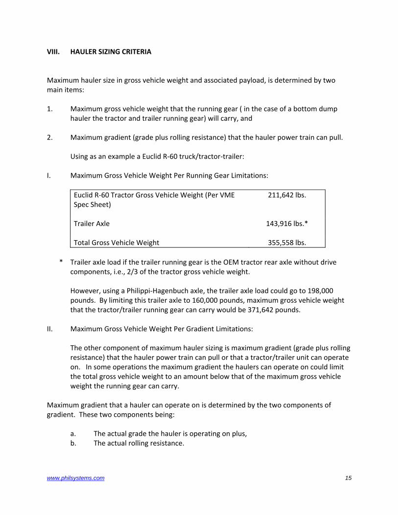
Maximum hauler size in gross vehicle weight and associated payload, is determined by two main items: 1. Maximum gross vehicle weight that the running gear ( in the case of a bottom dump
hauler the tractor and trailer running gear) will carry, and 2. Maximum gradient (grade plus rolling resistance) that the hauler power train can pull. Using as an example a Euclid R‐60 truck/tractor‐trailer: I. Maximum Gross Vehicle Weight Per Running Gear Limitations:
Euclid R‐60 Tractor Gross Vehicle Weight (Per VME Spec Sheet)
211,642 lbs.
Trailer Axle 143,916 lbs.*
Total Gross Vehicle Weight 355,558 lbs. * Trailer axle load if the trailer running gear is the OEM tractor rear axle without drive
components, i.e., 2/3 of the tractor gross vehicle weight. However, using a Philippi‐Hagenbuch axle, the trailer axle load could go to 198,000
pounds. By limiting this trailer axle to 160,000 pounds, maximum gross vehicle weight that the tractor/trailer running gear can carry would be 371,642 pounds.
II. Maximum Gross Vehicle Weight Per Gradient Limitations: The other component of maximum hauler sizing is maximum gradient (grade plus rolling
resistance) that the hauler power train can pull or that a tractor/trailer unit can operate on. In some operations the maximum gradient the haulers can operate on could limit the total gross vehicle weight to an amount below that of the maximum gross vehicle weight the running gear can carry.
Maximum gradient that a hauler can operate on is determined by the two components of gradient. These two components being:
a. The actual grade the hauler is operating on plus, b. The actual rolling resistance.
www.philsystems.com 15
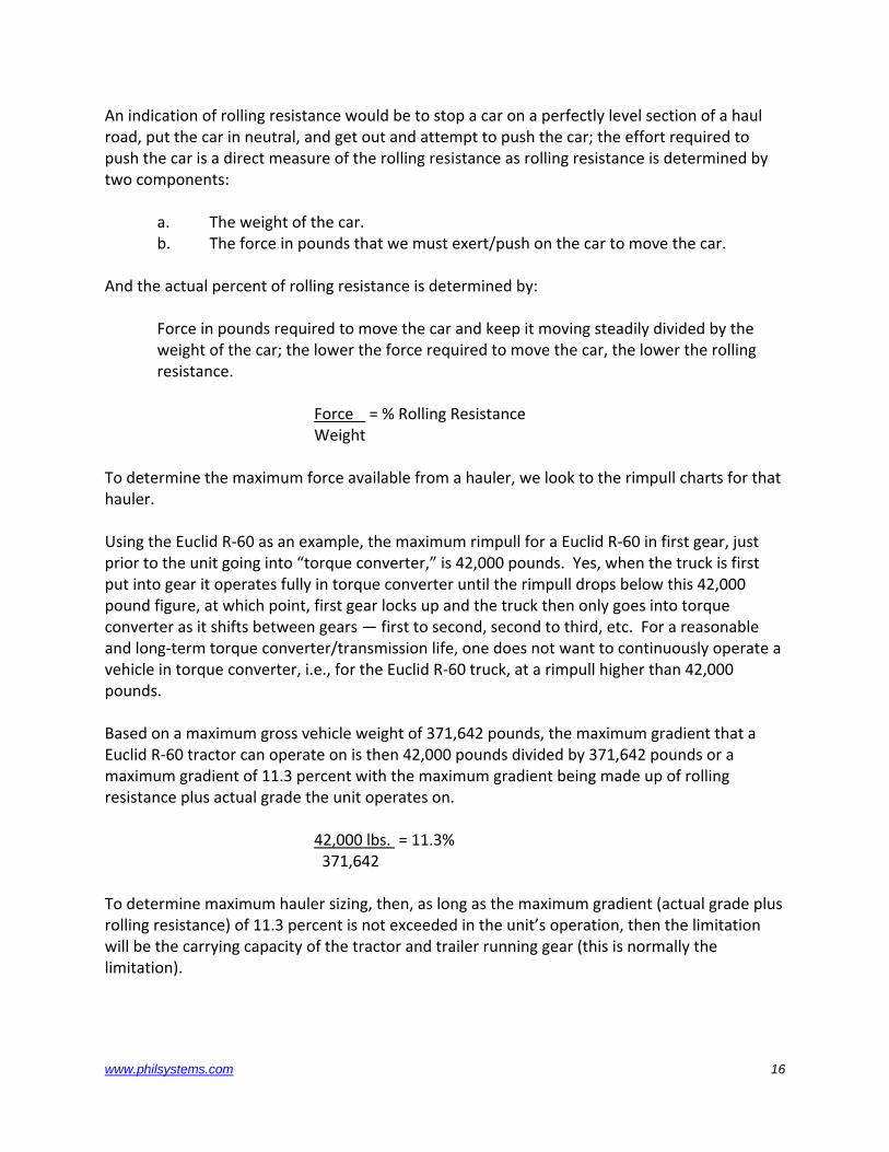
An indication of rolling resistance would be to stop a car on a perfectly level section of a haul road, put the car in neutral, and get out and attempt to push the car; the effort required to push the car is a direct measure of the rolling resistance as rolling resistance is determined by two components:
a. The weight of the car. b. The force in pounds that we must exert/push on the car to move the car.
And the actual percent of rolling resistance is determined by:
Force in pounds required to move the car and keep it moving steadily divided by the weight of the car; the lower the force required to move the car, the lower the rolling resistance.
Force = % Rolling Resistance Weight
To determine the maximum force available from a hauler, we look to the rimpull charts for that hauler. Using the Euclid R‐60 as an example, the maximum rimpull for a Euclid R‐60 in first gear, just prior to the unit going into “torque converter,” is 42,000 pounds. Yes, when the truck is first put into gear it operates fully in torque converter until the rimpull drops below this 42,000 pound figure, at which point, first gear locks up and the truck then only goes into torque converter as it shifts between gears — first to second, second to third, etc. For a reasonable and long‐term torque converter/transmission life, one does not want to continuously operate a vehicle in torque converter, i.e., for the Euclid R‐60 truck, at a rimpull higher than 42,000 pounds. Based on a maximum gross vehicle weight of 371,642 pounds, the maximum gradient that a Euclid R‐60 tractor can operate on is then 42,000 pounds divided by 371,642 pounds or a maximum gradient of 11.3 percent with the maximum gradient being made up of rolling resistance plus actual grade the unit operates on. 42,000 lbs. = 11.3% 371,642 To determine maximum hauler sizing, then, as long as the maximum gradient (actual grade plus rolling resistance) of 11.3 percent is not exceeded in the unit’s operation, then the limitation will be the carrying capacity of the tractor and trailer running gear (this is normally the limitation).
www.philsystems.com 16
IX. TRAILER COMPONENTS AND CONSIDERATIONS THEREOF
A. OVERALL TRAILER STRUCTURE The overall trailer structure can either be of a unitized/unibody design with uniform stress loading throughout the trailer structure with minimal stress concentrations at any point on the trailer or the trailer design can be such that the discrete components of the trailer are separated into integral parts and at each joint where these parts come together (hitch to trailer body, trailer body to rear axle mount, etc.) potential stress concentrations could develop. A unitized‐type of trailer construction is the best approach. Think of stress as water flow in a stream with the fewer obstructions to the flowing water the better. B. TRAILER TURNSTOPS Though the jackknifing of an off‐highway (bottom dump) trailer is very rare, it still can occur. Thus, the integrity of the turnstops which keep the trailer from turning around more than ninety degrees (90°) into the tractor/tractor cab is critical. Often times tractor‐trailer units are produced either with no turnstop of with minimal turnstops located within a few inches of the trailer hitch pin. If you have seen a vehicular accident where a camping trailer has come around on the towed vehicle, the importance of turnstops can readily be appreciated. The best turnstop is a turnstop that is substantially away from the trailer hitch point. A turnstop five to six feet (5‐6’) away from the trailer hitch point has far lower stresses and performs better in a tractor‐trailer jackknife than a turnstop that is only a foot or so away from the trailer hitch point.
www.philsystems.com 17
C. HITCH There are several trailer hitch configurations:
1. Simple ball studs – really only an enlarged version of a simple travel trailer hitch, 2. Fifth wheels – a variation of on‐highway tractor‐trailer hitches which do not
allow for trailer side‐to‐side movement, and 3. True off‐highway hitches that allow trailer oscillation in all directions – around
the tractor‐trailer, side‐to‐side relative to the tractor, and front‐to‐back relative to the tractor.
True, off‐highway hitches are more expensive but with that expense comes the comfort that a heavy‐duty off‐highway hitch is towing the trailer unit. After all, it is not 22 tons of payload that is being pulled. D. TRAILER BODY TO TRAILER HITCH TRANSITION STRUCTURE There are two schools of thought for this transition structure. One approach utilizes a design copied from common dirt scrapers. Scrapers utilize a torque tube to connect the scraper bowl arms to the scraper hitch. Similarly, some trailers utilize a torque tube to collect the load stresses at the front of the trailer body and once collected then transfer those stresses from the trailer body to the trailer hitch transition structure. This is somewhat analogist to rounding up a herd of cattle, reaching a critical point in the fence where all the cattle have to squeeze through, and then letting them go on the other side of the fence. The better approach is to use a trailer body to trailer hitch transition structure that allows for an even collection of the load stresses from the trailer body to the trailer hitch through an even, smooth transition structure. Designs such as this as typified by trailer hitches that connect back several feet along the inside and outside of the trailer body. The smooth transition of stresses from the trailer body to the trailer hitch keeps stress concentrations in this high stress area to a minimum. E. TRAILER BODY Trailer bodies, for the most part, are fairly basic. However, one of the distinguishing characteristics of the best trailer bodies is that the sides of the body are built like bridge trusses with an even flow of stress from one end of the trailer body to the other. Some trailer bodies, unfortunately, are built in such a manner that stress flow has not been accommodated or allowed for!
www.philsystems.com 18
Further, a trailer body that is as wide and as low as possible provides a much more stable bottom dump trailer. F. TRAILER DOORS Trailer doors are the moving parts of a bottom dump trailer. As such, doors produced using deep, high‐strength steel box sections designed to handle the various torsional stresses that occur as load is placed first in one end of the trailer then the other are a must. A door of a honeycomb design (airplane wing‐like) is far superior to a door that consists merely of a steel plate with ribbing/bolsters around the edge of the plate. The door structure can be subjected to considerable torsional stresses as the door operates up and down, as the door is loaded from one end to the other, as material might potentially jam in the door as it closes. G. DOOR ACTUATION Door actuation systems have almost as many approaches as the old saying goes, “Carter has liver pills.” The doors can be actuated with a single cylinder, two cylinders, or four cylinders. The actuation mechanism can be mechanical, it can be cable, it can be direct cylinder operated. There are a number of choices. It is important that opposing bottom dump trailer doors open simultaneously. If only one door opens, load can be left in the other side of the trailer and though this shouldn’t tip the trailer over, it can be a bit hairy as the door is forced open by whatever means so the load can be discharged. From a safety consideration standpoint, a door actuation system that guarantees both doors opening simultaneously is a significant plus. A door actuation mechanism that utilizes a single cylinder hooked to a cable reeving system to simultaneously loosen the cable holding both doors does not guarantee simultaneous door operation as one of the cables may snag in the reeving system, etc. A system where cylinders operating the doors are direct connected to the doors means that the doors have the potential to operate independently. Yes, various hydraulic flow‐control methods can be installed so that the cylinders should operate together. However, simultaneous door opening is by no means assured as a hydraulic line could break and a door come open. A door mechanism operating with a door closed over‐center, dead‐center link means no force whatsoever on the door actuating hydraulic cylinder with the doors closed – rather with a
www.philsystems.com 19
mechanical link in the dead‐center position the door will remain closed. And, by hooking up the dead‐center link for each door to a single hydraulic cylinder when that hydraulic cylinder brings the door links off of dead‐center, it is guaranteed that both doors will open simultaneously. Are the drawbacks to a single hydraulic cylinder operating dead‐center links to actuate the doors? Yes! There is additional linkage to deal with. However, if the linkage is properly designed it is basically trouble‐free. A significant plus of this approach is that the doors have to operate in tandem. This compares with two or more cylinders hooked direct to the door which, though simpler, has the potential of only one door opening or the doors opening erratically‐ left door, right door, right door, left door, etc. The pluses of a cylinder/cable system are one cylinder and the minuses are the doors are fully supported by this cylinder and cable reeving so that if either the cable frays or a hydraulic line bursts, one or both doors may open at the wrong time. H. TRAILER BODY TO TRAILER REAR AXLE TRANSITION STRUCTURE This trailer component parallels that of the trailer body to trailer hitch transition structure. One approach for attaching the trailer rear axle transition structure to the trailer body is to work with structural tubing attached to the trailer body at, typically, four (4) to six (6) points. This structural tubing is generally relatively small – 6” X 8”, 8” X 10” – whatever the size may be. The plus of using this structural tubing is that for the trailer manufacturer, the structural tubing is generally an off‐the‐shelf item. The minuses, are that at each point where this structural tubing is attached to the trailer body, a high point of stress concentration occurs – a stress concentration which can and will lead to the potential of stress cracking. A better approach to attaching the trailer rear axle transition structure to the trailer body is to fabricate a trailer rear axle transition structure made up of high‐strength steel plate designed so the attachment points of the rear axle transition structure to the trailer body tie in to both the trailer sidewalls and the rear trailer bulkhead over approximately 60 percent of the area of the trailer bulkhead/trailer sidewall connection. This type of fabricated rear axle transition structure has four (4) large, rectangular areas of contact with the trailer sidewall/trailer rear bulkhead. These four large, rectangular areas of contact are located on each corner of the trailer body allowing a smooth transition of load stresses from the trailer body to the trailer rear axle transition structure.
www.philsystems.com 20
I. TRAILER AXLE The alternatives for trailer axle are:
• Stub axles welded to the trailer rear axle transition structure, • Stub axles bolted to the trailer rear axle transition structure, • Stub axles bolted to an axle tube mounted to the trailer rear axle transition
structure, and • A solid axle shaft mounted to the trailer rear axle transition structure.
A stub axle welded to the trailer rear axle transition structure/the stub is more economical from a production standpoint. However, if axles ever wear and need replacement, the trailer owner is in for a real challenge. Yes, the stub axle can be cut out and a new stub axle welded in. However, that can only be accomplished with considerable expense. If stub axles are going to be used, it is far better to bolt the stub axle either to the rear axle transition structure or to an axle shaft which is then mounted to the rear axle transition structure. However, if the point at which the stub axles are bolted to the rear axle transition structure ever experiences a failure, then considerable expense can be incurred in repairing, fixing this stub axle mounting. The better approach for axle mounting, whether it be stub axles or a solid axle shaft, is to in the case of stub axles mount them to an axle tube which is mounted to the rear axle transition structure. And, in the case of the solid axle shaft, direct‐mount the axle shaft to u‐type clamps on the rear axle transition structure. Note: Typically, in more sophisticated axle braking arrangements, a stub axles is required while with more straight‐forward braking approaches, dry disc or drum, a solid axle shaft can be used and would be the preferred approach.
www.philsystems.com 21
J. TRAILER AXLE SUSPENSION The choices her are two – suspended or unsuspended. The approach to this question is determined by loaded unit haul speeds and the haul road condition. Basically, a loaded tractor‐trailer unit, unsuspended, can operate at 25, 27 and in some cases, max 30 miles per hour over good, smooth roads. If the roads are badly rutted then an unsuspended tractor‐trailer unit should operate at lesser speeds. All dependent on road condition. A suspended trailer axle allows for higher operating speeds and accommodates rougher haul roads. However, suspended axles add sophistication to a basic, simple tractor‐trailer unit and may perform marginally at best. Types of suspensions are:
• Fixed‐link axle suspension. In a fixed‐link axle suspension, the rear axle is attached to the trailer by two (2) links coming forward from the rear axle, to a pivot on the trailer rear axle transition structure and the axle rotates up and down parallel to and about this pivot. In a fixed‐link suspension approach, both sets of tires or, as the case may be, both sets of dual tires, move in unison about the fixed‐link axle suspension pivot. As the rear axle thus moves, the trailer may “wobble side‐to‐side.”
• Independent axle suspension, an alternative to the fixed‐link axle suspension is an
independent axle suspension movement. This type of suspension has one (1) link coming forward from the trailer axle. This link goes to a single pivot point versus, in the fixed‐link axle suspension, two (2) pivot points. In an independent axle movement suspension, the fixed‐link attaches in the center (side‐to‐side) of the trailer allowing the ends of the trailer axle to move up and down and individually/independently. An independent trailer axle suspension has an additional dog‐bone link holding the axle laterally side‐to‐side relative to the trailer.
An independent axle suspension arrangement, typically, uses two (2) conventional charged suspension cylinders to hold the trailer up and level. If pressure charges are different in the two (2) suspension cylinders or if one suspension cylinder leaks, the trailer will lean to the lower‐charged suspension cylinder. A general recommendation relative to suspended trailer axles is to avoid them where possible. However, if they are required because of haul road conditions or the need to run at higher haul road speeds than 27 to 30 miles an hour, by all means, use a suspended trailer axle.
www.philsystems.com 22
A fixed trailer axle suspension is very simple. The axle is rigidly fixed to the trailer rear axle transition structure. This is definitely a much simpler trailer axle mounting approach. The minus of fixed‐axle mounting is that the tires, in reality, function as the trailer suspension and, in a loaded condition, if the roads are very rough, the trailer tires may have a tendency to flex and heat up as they operate as the trailer rear axle suspension system. If loaded haul road speeds, over smooth haul roads, are kept to 25 to 27 max 30 miles an hour, and the roads are in good condition then a fixed trailer axle suspension mount is more than adequate. K. TRAILER BRAKES Just as item B, turnstops, a safety related matter, so are the trailer brakes. It is one issue to get a haul unit operating and moving, it is an entirely different issue to get it stopped. Basically, three options exist for trailer brakes:
1. Conventional brake shoe/drum braking, 2. Dry disc brakes, 3. Wet disc brakes.
Of the braking options, the conventional drum/brake shoe and the dry disc brake are relatively straight‐forward breaking alternatives, while the wet disc brake alternative does bring with it a fairly high degree of brake complexity. (Just as the name wet implies, wet brakes operate in a wet bath, typically oil, supplied by the tractor with the tractor and trailer plumbed accordingly). When do you use which braking alternative? That question is best answered by the severity of the braking operation expected to be encountered. In terms of braking capability, drum/brake shoes have a moderate braking capability. Dry disc brakes have a moderately high braking capability, while wet disc brakes have a high braking capability though dry disc brakes and wet disc brakes have almost the same braking capability. And that, really, is where the braking option question ends. Yes, there are various arguments for how much brake service may be required and how hard or easy it will be to service the brakes. However, all of these distill down to how much trailer brake use is anticipated and what degree of braking severity is required in a particular haulage operation. From Philippi‐Hagenbuch, Inc.’s review of the Sand & Gravel operation, we would rate the degree of braking severity required as very moderate. Wet disc brakes have been used extensively in off‐highway trucks and they are extremely successful brakes. Wet disc brakes are, however, more complex, more expensive and wet disc brakes contain far more service parts.
www.philsystems.com 23
Philippi‐Hagenbuch, Inc. has built trailers with both drum/brake shoe braking systems and with wet disc braking systems. The advantage of the drum and brake show braking system is the simplicity of the brake system. The advantage of the wet disc brake is a higher degree of braking capability. The choice of braking systems is really one for the purchaser to make based on past experience and maintenance requirements of each braking approach. However, from Philippi‐Hagenbuch, Inc.’s standpoint, the recommendation for the Sand & Gravel Plant, if it were our option, would be dry disc brakes or conventional drum/brake shoes. L. STEEL The question of steel is similar to having the finest diamond cutter in the world trying to cut diamonds from a flawed stone. The importance of the steel used is any product is equally as important as the design of that product. The design of the product can be the best in the world. However, that design will only be as good as the raw materials it is produced from. There are many different schools of thought relative to the steel to use in a product such as a bottom dump trailer. One school of thought is that you do not weld T‐1 to T‐1 steel. Another school of thought is that mild 60,000 – 80,000 p.s.i. yield steel, will give and flex better than a higher strength, potentially harder, steel. However, when it all washes out, the real reason for running haulage equipment at the Curles Neck Sand & Gravel Plant is to haul material, not move steel, and the most efficient material haulage occurs through the use of high‐strength dead weight reducing steel incorporated into a well‐thought‐out haulage unit design/ The recommended steel for use in the construction of a bottom dump trailer for producing the floor, sides, bulkhead plates, trailer body ribs, trailer body bolsters, trailer body to trailer hitch transition structure and trailer body to rear axle transition structure is a steel having a nominal yield of 165,000 p.s.i. with a corresponding minimum Brinell hardness of 400 and a nominal Brinell hardness of 420. And, interestingly enough, one such steel that fits these requirements has better cold weather strengths than a steel that is 40 percent as strong. Thus, one shouldn’t automatically assume that high‐strength steel sacrifices ductility or workability‐ rather, today, the high‐strength quench and tempered steels that are available, are the steels of choice in the production of off‐highway haulage equipment.
www.philsystems.com 24
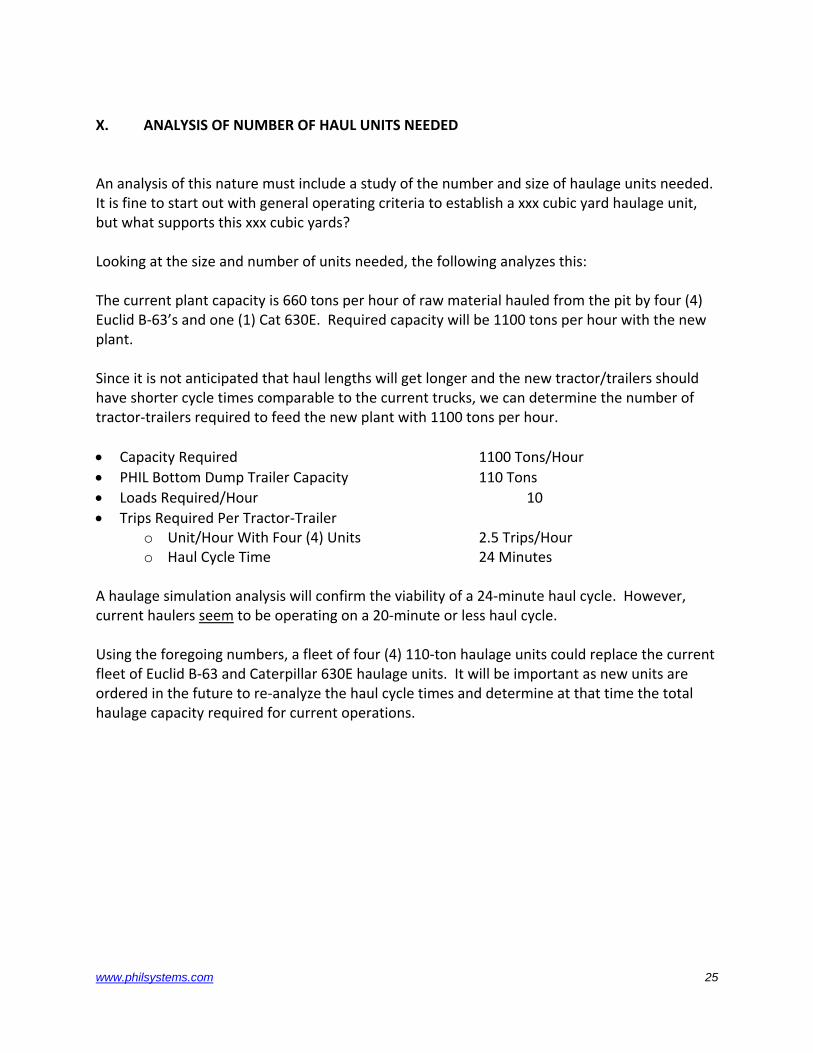
X. ANALYSIS OF NUMBER OF HAUL UNITS NEEDED An analysis of this nature must include a study of the number and size of haulage units needed. It is fine to start out with general operating criteria to establish a xxx cubic yard haulage unit, but what supports this xxx cubic yards? Looking at the size and number of units needed, the following analyzes this: The current plant capacity is 660 tons per hour of raw material hauled from the pit by four (4) Euclid B‐63’s and one (1) Cat 630E. Required capacity will be 1100 tons per hour with the new plant. Since it is not anticipated that haul lengths will get longer and the new tractor/trailers should have shorter cycle times comparable to the current trucks, we can determine the number of tractor‐trailers required to feed the new plant with 1100 tons per hour. • Capacity Required 1100 Tons/Hour • PHIL Bottom Dump Trailer Capacity 110 Tons • Loads Required/Hour 10 • Trips Required Per Tractor‐Trailer
o Unit/Hour With Four (4) Units 2.5 Trips/Hour o Haul Cycle Time 24 Minutes
A haulage simulation analysis will confirm the viability of a 24‐minute haul cycle. However, current haulers seem to be operating on a 20‐minute or less haul cycle. Using the foregoing numbers, a fleet of four (4) 110‐ton haulage units could replace the current fleet of Euclid B‐63 and Caterpillar 630E haulage units. It will be important as new units are ordered in the future to re‐analyze the haul cycle times and determine at that time the total haulage capacity required for current operations.
www.philsystems.com 25
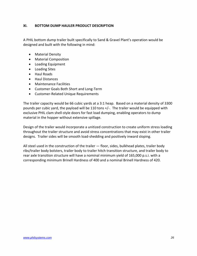
XI. BOTTOM DUMP HAULER PRODUCT DESCRIPTION
A PHIL bottom dump trailer built specifically to Sand & Gravel Plant’s operation would be designed and built with the following in mind:
• Material Density • Material Composition • Loading Equipment • Loading Sites • Haul Roads • Haul Distances • Maintenance Facilities • Customer Goals Both Short and Long‐Term • Customer‐Related Unique Requirements
The trailer capacity would be 66 cubic yards at a 3:1 heap. Based on a material density of 3300 pounds per cubic yard, the payload will be 110 tons +/‐. The trailer would be equipped with exclusive PHIL clam shell‐style doors for fast load dumping, enabling operators to dump material in the hopper without extensive spillage. Design of the trailer would incorporate a unitized construction to create uniform stress loading throughout the trailer structure and avoid stress concentrations that may exist in other trailer designs. Trailer sides will be smooth load‐shedding and positively inward sloping. All steel used in the construction of the trailer — floor, sides, bulkhead plates, trailer body ribs/trailer body bolsters, trailer body to trailer hitch transition structure, and trailer body to rear axle transition structure will have a nominal minimum yield of 165,000 p.s.i. with a corresponding minimum Brinell Hardness of 400 and a nominal Brinell Hardness of 420.
www.philsystems.com 26
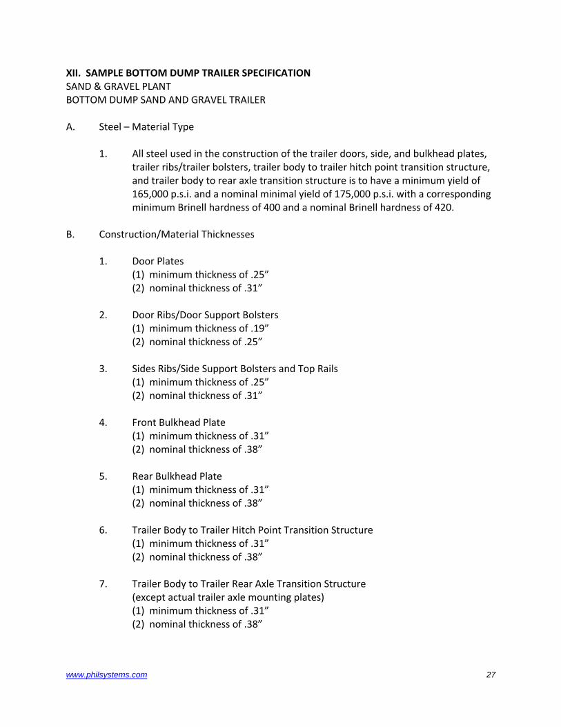
XII. SAMPLE BOTTOM DUMP TRAILER SPECIFICATION SAND & GRAVEL PLANT BOTTOM DUMP SAND AND GRAVEL TRAILER A. Steel – Material Type
1. All steel used in the construction of the trailer doors, side, and bulkhead plates, trailer ribs/trailer bolsters, trailer body to trailer hitch point transition structure, and trailer body to rear axle transition structure is to have a minimum yield of 165,000 p.s.i. and a nominal minimal yield of 175,000 p.s.i. with a corresponding minimum Brinell hardness of 400 and a nominal Brinell hardness of 420.
B. Construction/Material Thicknesses 1. Door Plates (1) minimum thickness of .25” (2) nominal thickness of .31”
2. Door Ribs/Door Support Bolsters (1) minimum thickness of .19” (2) nominal thickness of .25”
3. Sides Ribs/Side Support Bolsters and Top Rails (1) minimum thickness of .25” (2) nominal thickness of .31”
4. Front Bulkhead Plate (1) minimum thickness of .31” (2) nominal thickness of .38”
5. Rear Bulkhead Plate (1) minimum thickness of .31” (2) nominal thickness of .38”
6. Trailer Body to Trailer Hitch Point Transition Structure (1) minimum thickness of .31” (2) nominal thickness of .38”
7. Trailer Body to Trailer Rear Axle Transition Structure (except actual trailer axle mounting plates)
(1) minimum thickness of .31” (2) nominal thickness of .38”
www.philsystems.com 27
C. Capacities/Dimensions/Design Parameters
1. Trailer is to be designed for hauling sand and gravel with a density of 3,300 pounds per cubic yard.
2. Trailer is to be designed to a load heap specification of 3 to 1. 3. The maximum gross vehicle weight rating of the loaded tractor‐trailer
combination shall not exceed 110% of tire ratings. The trailer quoted is to be sized so as to fully utilize the gross vehicle weight rating of the tractor/trailer running gear and tractor rimpull.
4. The loaded tractor‐trailer combination is to have an approximate weight distribution of 20% on the steering axle of the tractor, 40% on the drive axle of the tractor, and 40% on the trailer axle.
5. The trailer axle is to be rigidly attached to the trailer body. 6. Approximate Bottom Dump Trailer operating dimensions are to be +/‐:
• overall width 14’0” +/‐ • overall height 13’9” +/‐ • trailer length 68’1” +/‐ • trailer ground clearance 2’11” +/‐
D. Trailer Construction Features
1. The trailer will be designed in a manner to utilize the maximum Gross Vehicle Weight of the tractor and trailer running gear used. The unloading doors shall operate simultaneously and in a manner to maximize the unloading rate, minimize unloading times and maximize productivity.
2. Trailer sides are to be sloping inward from the top to bottom at an angle that accommodates unloading but minimizes bridging of the load during unloading.
3. The inside of the trailer sides are to be smooth and load shedding with no internal trailer side reinforcement structures/ribs protruding into the inside of the trailer which might impede material unloading.
4. Trailer doors are to be flat, load shedding and of a construction suitable for withstanding loading impact of material loaded by a dragline or backhoe.
5. Trailer is to have a unitized middle divided to strengthen the body sides and provide trailer body integrity.
6. Trailer is to have a push block extending a minimum of five (5) feet behind the rear tires.
7. Trailer is to have trailer axle fenders to keep material from being thrown up on the trailer.
8. The trailer is to have a back up alarm, stop lights and a back‐up light. 9. Trailer construction is to be of a fully unitized design for even (structural) load
stress distribution. 10. The trailer “hitch to body” transition structure should provide a smooth
distribution of load stress from the trailer body to the trailer hitch.
www.philsystems.com 28
11. The trailer axle mounting structure should provide a 4‐point attachment from the rear axle structure to the trailer body to transfer load stresses in a smooth transition from the trailer body to the trailer rear axle mounting structure.
E. Tires
1. The trailer is to be equipped with tires providing a uniform, and even ground pressure (radial) over the entire tire footprint.
2. The trailer will utilize the same tire size as the tractor. 3. The trailer is to have dual tires.
F. Trailer Axle 1. The trailer is to have a solid axle shaft.
2. The trailer axle is to have a minimum load rating of 160,000 pounds 3. The trailer will have drum brakes or dry disc brakes sized to the trailer and
controlled in a manner compatible with the tractor used. 4. The trailer axle assembly is not to be welded to the trailer body and is to be
completely removable in two (2) hours and replaceable with another axle, (with rims and tires pre‐mounted) in three (3) hours.
G. Dumping Features and Characteristics
1. The trailer dumping operation must provide for full, unrestricted material dumping with minimal internal trailer impediments to the flow of material from the trailer.
2. One hydraulic cylinder will be used to control trailer door actuation. 3. Trailer doors are to positively lock (over dead center) in the closed position. 4. Trailer doors are to be sloped in the open position to facilitate load release and
guide material into a hopper. The dimensions of the trailer unloading opening are to be 6’ by 16’10” or greater to allow easy positioning of the trailer over the unloading grate which is 8’4” by 30’ 1 ½”.
5. Trailer doors are to have an “open/closed” position indicator visible within the driver’s normal forward line of sight.
H. Tractor Kingpin Hitch and Hitch Structure
1. Hitch structure is to consist of a single hitch subframe with integral anti‐jackknife turn stops and hitch kingpin mounts.
2. Hitch shall consist of a yoke and separate kingpin for universal 6‐way trailer towing.
www.philsystems.com 29
3. Hitch kingpin is to be mounted to hitch subframe. 4. Tractor kingpin hitch structure is to be pinned to chassis like a dump body and
utilize dump body guides. 5. Tractor kingpin hitch structure is to connect to tractor chassis with adjustable
links between the chassis dump cylinder mounts and the hitch structure. 6. Tie bolts are to be used around the tractor chassis frame members to mount the
hitch structure as appropriate. 7. Tractor kingpin hitch structure is not to be welded to the tractor chassis. 8. Anti‐jackknife turn stops are to be an integral part of the kingpin hitch
substructure and not welded or attached directly to the chassis frame. 9. Anti‐jackknife turn stop contact points with trailer hitch/tongue must be no less
than 60” horizontally from the center of the hitch kingpin. 10. The tractor rear axle fenders and decking are to be mounted and attached to the
hitch subframe. 11. The hitch kingpin is to be set up with a central lube point. 12. Wherever possible all subframe and hitch components shall be standard
tractor/trailer OEM components. I. Option 1. Side marker lights for trailer.
Other Specifications A. Other Conditions
1. The tractor/trailer will be set‐up complete at the Sand and Gravel Plant, with the following:
a. Tires and doors mounted b. The trailer hooked to the tractor
c. Air, hydraulic and electrical lines from the trailer connected to the tractor lines at the hitch
d. The hitch structure with integral turn stops mounted and installed and air lines and hydraulic lines plumbed. Controls for hydraulic and air systems mounted in the tractor cab.
B. Documentation
1. The delivered trailer documentation will include a scaleable 1/16 scale or larger (1/12, 1/10) layout drawing illustrating the tractor with bottom dump trailer and detail drawings of the door actuation and trailer dumping operation.
www.philsystems.com 30
2. Trailer documentation will include a list of all trailer components which are unique or special to the trailer. These are items that would not normally be considered off‐the‐shelf purchased items from an industrial supply house or equipment dealership.
3. Trailer documentation will include a recommended list of spare parts, with prices, that should be carried in inventory by the Sand and Gravel Plant.
C. Bid/Quotation Conditions for Tractor/Trailer Combination
1. All bids to be considered responsive and acceptable must include both a scaleable 1/16 or larger (1/12, 1/10) and a 1/32 layout drawing of the proposed tractor‐trailer combination illustrating tractor with bottom dump trailer, including detail of trailer dumping operation/door(s) and all the above operation.
2. All bids to be considered responsive and acceptable must include complete trailer specifications, confirmation of the bid meeting all the above specifications is required in bid response text.
3. For bid to be considered responsive, bidder must furnish a list of all trailer components which are unique/special to trailer being quoted (i.e. items which would not normally be considered off‐the‐shelf purchased items from mill/industrial supply houses, etc.)
4. For bid to be considered responsive, bidder must furnish a recommended list of space parts, with their respective prices, that should be carried in inventory by purchaser.
5. All tractor‐trailer combination weights and dimensions to be confirmed at time of final design approval by purchaser. Prior to production beginning on any order that may result from this bid request, final design drawings will be forwarded to purchaser for purchaser’s approval. Vendor to begin production only upon receipt of these signed approval drawings.
www.philsystems.com 31
APPENDIX The balance of this presentation is an addendum that covers various relevant material related to Philippi‐Hagenbuch, Inc., and the recommended purchase of Philippi‐Hagenbuch, Inc. bottom dump tractor‐trailer units. 1. Philippi‐Hagenbuch, Inc. Background 2. Philippi‐Hagenbuch, Inc. Special Application Body Design/Produced Listing 3. United States Patents Held By LeRoy G. Hagenbuch, P.E.
www.philsystems.com 32
www.philsystems.com 33
APPENDIX 1 PHILIPPI‐HAGENBUCH, INC.
BACKGROUND
Philippi‐Hagenbuch, Inc. (PHIL) is a sales‐engineering firm formed in 1969 for the express purpose of improving various phases of off‐highway equipment haulage. PHIL is the one company in the world specializing in off‐high truck haulage components, attachments, and products.
Initially, PHIL developed the patented Autogate® Tailgate, an automatic, mechanically‐activated, hydraulic‐free off‐highway truck tailgate.
Working closely with truck manufactures, tailgates are custom designed for all makes and models of off‐highway trucks. The Autogate® Tailgate is working in all types of applications — from ore to soupy material and on trucks from 10 to 340 ton capacity. Autogate® Tailgates have been installed throughout the United States, Canada, South America, Mexico, Puerto Rico, the West Indies, Honduras, England, West Germany, Africa, Cyprus, Indonesia, the Philippines, Japan, China, the Middle East, Australia, and India.
The PHIL HIVOL® truck body was introduced in 1975. Using a high‐strength steel to minimize body weight and maximize body size, the trucks’ chassis can carry more payload and less non‐productive weight. Today, HIVOL® bodies are working on Caterpillar, Euclid‐Hitachi, John Deere, Komatsu, Liebherr, Moxy, Terex and Volvo and Unit Rig trucks ranging from 25 to 340 ton capacity. The HIVOL® body is recommended for lightweight to highly abrasive material applications including coal, flyash, coal/overburden, oil sands, iron ore, etc. The PHIL APPLICATION SPECIFIC BOTTOM DUMP TRAILER was introduced in 1986. Also, using a high‐strength steel to minimize body weight and maximize body size, trailer‐tractor units pull more payload and less dead weight. Looking at payload/weight ratio, a 50‐ton tractor can pull a PHIL trailer hauling 110 tons of payload. PHIL welcomes the opportunity to design other products to accommodate customers’ haulage needs. Our engineering staff is led by company co‐founder and registered professional engineer, LeRoy Hagenbuch. Having over twenty‐five years of experience in the mining haulage industry, LeRoy holds numerous patents covering all aspects of material management and haulage. PHIL’s Standard Product Division has a variety of over twenty (20) different products. Other PHIL off‐highway truck haulage options include the patented OBDAS® Truck Vehicle Management System, coke bodies, patented hot slag bodies, sideboards, patented load ejectors, and patented top covers.