Embed Size (px)
Citation preview
Hastings Operation & Maintenance
Manual
Table of Contents ST. CROIX FEATURES.......................................................................................2 INSTALLATION.................................................................................................. 3 PREVENTING CHIMNEY FIRES .....................................................................3 SATISFACTORY PERFORMANCE................................................................. 3 APPROVED FUELS .............................................................................................3 Pellets, Cherry Pits & Pellet /Corn mix ...................................................3 OPERATING INSTRUCTIONS......................................................................... 4 Control Board Features.............................................................................4 Thermostat Function – How does it work? .............................................5 Pre-Lighting Instructions..........................................................................6 Lighting Your Stove ................................................................................. 6 Shutting the Stove off ............................................................................... 6 Diagnostic Features................................................................................ 6-7 Safety Features ...........................................................................................7 COMBUSTION AIR DAMPER ...................................................................... 7-8 Flame Pattern Characteristics ..................................................................8 MAINTAINING THE STOVE ............................................................................9 Daily Maintenance ........................................................................... 10-11 Periodic Maintenance ...................................................................... 11-12 Yearly Maintenance ......................................................................... 13-14 SAFE OPERATION ........................................................................................... 15 TROUBLESHOOTING AND FAQ ............................................................ 16-20 WARRANTY........................................................................................................21 PARTS LAYOUT ............................................................................................... 22 Cast Iron Parts ........................................................................................ 22 Parts Layout .......................................................................................23-25
208
Hastings Operations Manual Page 1
Dear St. Croix Wood Pellet Stove Owner: Congratulations! Your purchase of a St. Croix wood pellet stove places you among a select group of individuals who have demonstrated their concern about residential heating efficiency and our environment. This owner's manual is designed to help you obtain maximum benefit from your St. Croix wood pellet stove. Please read this manual in its entirety BEFORE operating your pellet stove. During the manufacturing process every effort has been expended to ensure that each St. Croix wood pellet stove meets the highest quality standards of material and workmanship. Here are some important aspects of wood pellet stove installation and operation which you must observe in order to obtain maximum comfort and safety from your new St. Croix wood pellet stove. 1. Have your new St. Croix wood pellet stove installed by trained, qualified personnel. 2. Use only clean, dry quality wood pellets that are known to burn satisfactorily in your
stove. 3. Faithfully adhere to the maintenance program described in this manual. Thank you
for selecting a St. Croix wood pellet stove as the environmentally preferred answer to your residential heating needs.
Hastings Operations Manual Page 2
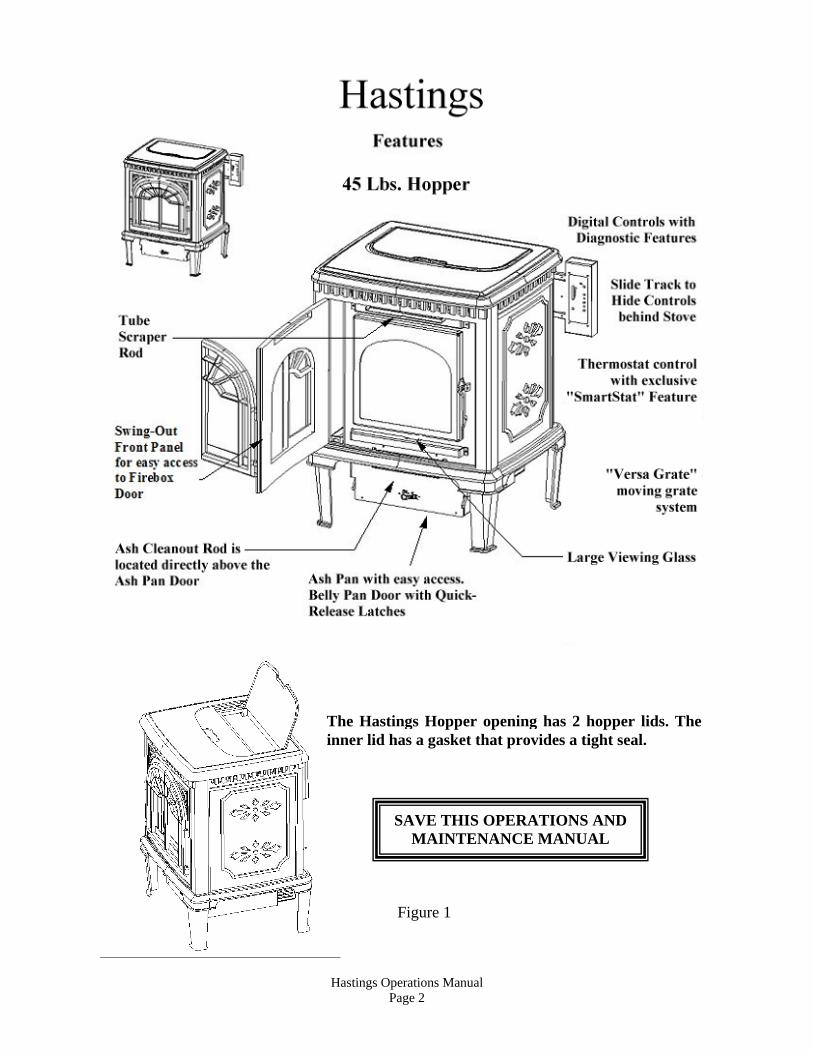
SAVE THIS OPERATIONS AND MAINTENANCE MANUAL
Figure 1
The Hastings Hopper opening has 2 hopper lids. The inner lid has a gasket that provides a tight seal.
Hastings Operations Manual Page 3
Operation and Maintenance Hastings Wood Pellet Stove
CAUTION: Operate this unit only with the fuel hopper lid closed. Failure to do so may result in emission of products of combustion from the hopper under certain conditions. Maintain hopper seal in good condition.
INSTALLATION Proper installation is essential for safety, effective operation, warranty coverage, insurance requirements and to meet local building codes. Installation requirements are described in the Installation Manual included with your new stove. PREVENTING CHIMNEY FIRES Chimney fires can be prevented by properly operating the stove and by periodic inspection and cleaning of the chimney. When wood is burned it produces tar and other organic vapors, which combine with expelled moisture to form creosote. The creosote vapors condense in the relatively cool chimney flue associated with a slow burning fire. As a result, creosote residue accumulates on the flue lining. When ignited this creosote can result in an extremely hot chimney fire. The chimney and chimney connector should be inspected at least once every two months during the heating season to determine if a creosote build-up has occurred. If a significant layer of creosote has accumulated (3 mm or more) it should be removed to reduce the risk of a chimney fire. Use of an appropriately sized chimney brush or the services of a professional chimney sweep are recommended. SATISFACTORY PERFORMANCE The keys to satisfactory performance are: proper operation of the stove, diligent maintenance and burning only dry, clean, quality fuel. Clinkers and ash are a by-product of combustion and are not caused solely by your stove. Stove performance can be quickly and severely reduced if poor quality pellets are used. APPROVED FUELS
PELLETS NOTE: Contact your dealer for more information on APFI approved wood pellet fuels. Pellets with excessive sawdust should be screened by sifting with 1/4" mesh screening. Store Pellets under cover on a wooden pallet or other methods to ensure they do not become rain soaked or absorb moisture from damp or wet floors. Do not store pellets within stove installation clearances or within the space required for ash removal. The stove is not warranted against damage caused by poor pellets, incorrect operation, poor maintenance or incorrect installation. CHERRY PITS Cherry Pits will burn much in the same manner as pellets. They will have higher ash content than Premium Pellets. Adjust your maintenance schedule accordingly. No standards exist for cherry pits as a fuel. Inspect fuel before purchasing. The stove is not warranted against damage caused by poor cherry pits, incorrect operation, poor maintenance or incorrect installation. ADD CORN TO THE MIX The Hastings is approved to burn a mixture of pellets and corn (maximum 50% corn). The Thermostat Switch should be set to the Manual position. (See Fig. 2 on page 5) Operation of the stove doesn’t change when burning a mixture of pellets and corn. The burn pot will need to be cleaned on a daily basis, using the “Pot Scraper Tool” shown in figure 3 on page 8. Use the Pot Scraper Tool to remove any clinkers that build up because of the corn when needed. For more information, read the Daily, Periodic and Yearly Maintenance section towards the back of this manual. OPERATING INSTRUCTIONS
Hastings Operations Manual Page 4
A different type of heater. The pellet stove is neither a cord wood stove nor a furnace. Its operation and maintenance differ from the tra-ditional wood stove. FOLLOW THESE OPERATING INSTRUCTIONS EXACTLY AS STATED TO ENSURE SAFE AND RELIABLE OPERATION. 1. Carefully read this “Operation and Mainte-nance” manual in its entirety BEFORE lighting your stove for the first time. 2. Obtain final inspection and approval of installation from local building officials. 3. Carefully clean all marks off the gold plated parts before the first fire is lighted. Use a soft cloth and a “Windex” type cleaner. Caution: Never use an abrasive cleaner on any plated or painted parts of the stove. 4. Have your dealer demonstrate all the opera-tional and maintenance steps necessary for proper use of the stove. Sign and return the warranty card, to the address listed on the back page. 5. Some odors may be given off during the first few hours of burning during initial break-in. These odors are normal and not harmful. However, ventilating the room until the odors disappear is recommended. 6. The stove will become HOT while in operation. Keep children, clothing and furniture away from all stove surfaces. WARNING: Direct contact with the stove while operating may cause skin burns. 7. To avoid the possibility of smoke and/or sparks entering the room always keep firebox and de-ashing doors closed whenever the stove is operating. 8. A certain amount of carbon monoxide may be produced within the stove as a by-product of combustion. All exhaust vent connections must be sealed with RTV silicone to assure a gas tight seal. Any leaks into a confined area caused by faulty installation or improper operation of the stove could produce dizziness, nausea and in extreme cases, death. 9. An outside source of combustion air is required on all mobile home installations. If room air is used to supply combustion air, room air starvation, operation of exhaust fans and icing of
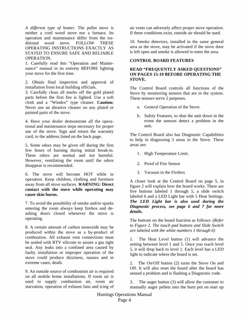
air vents can adversely affect proper stove operation. If these conditions exist, outside air should be used. 10. Smoke detectors, installed in the same general area as the stove, may be activated if the stove door is left open and smoke is allowed to enter the area. CONTROL BOARD FEATURES READ “FREQUENTLY ASKED QUESTIONS” ON PAGES 15-19 BEFORE OPERATING THE STOVE. The Control Board controls all functions of the Stove by monitoring sensors that are in the system. These sensors serve 2 purposes.
a. General Operation of the Stove.
b. Safety Features, to shut the unit down in the event the sensors detect a problem in the unit.
The Control Board also has Diagnostic Capabilities to help in diagnosing 3 areas in the Stove. These areas are:
1. High Temperature Limit. 2. Proof of Fire Sensor
3. Vacuum in the Firebox
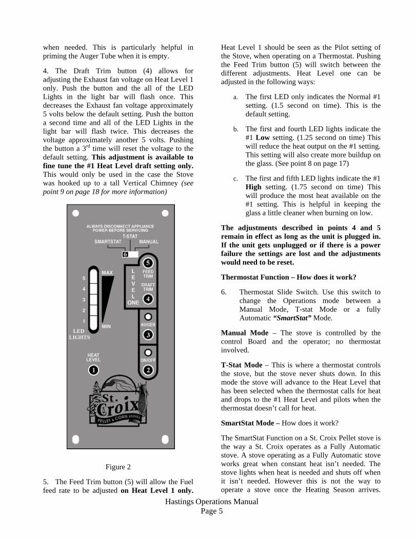
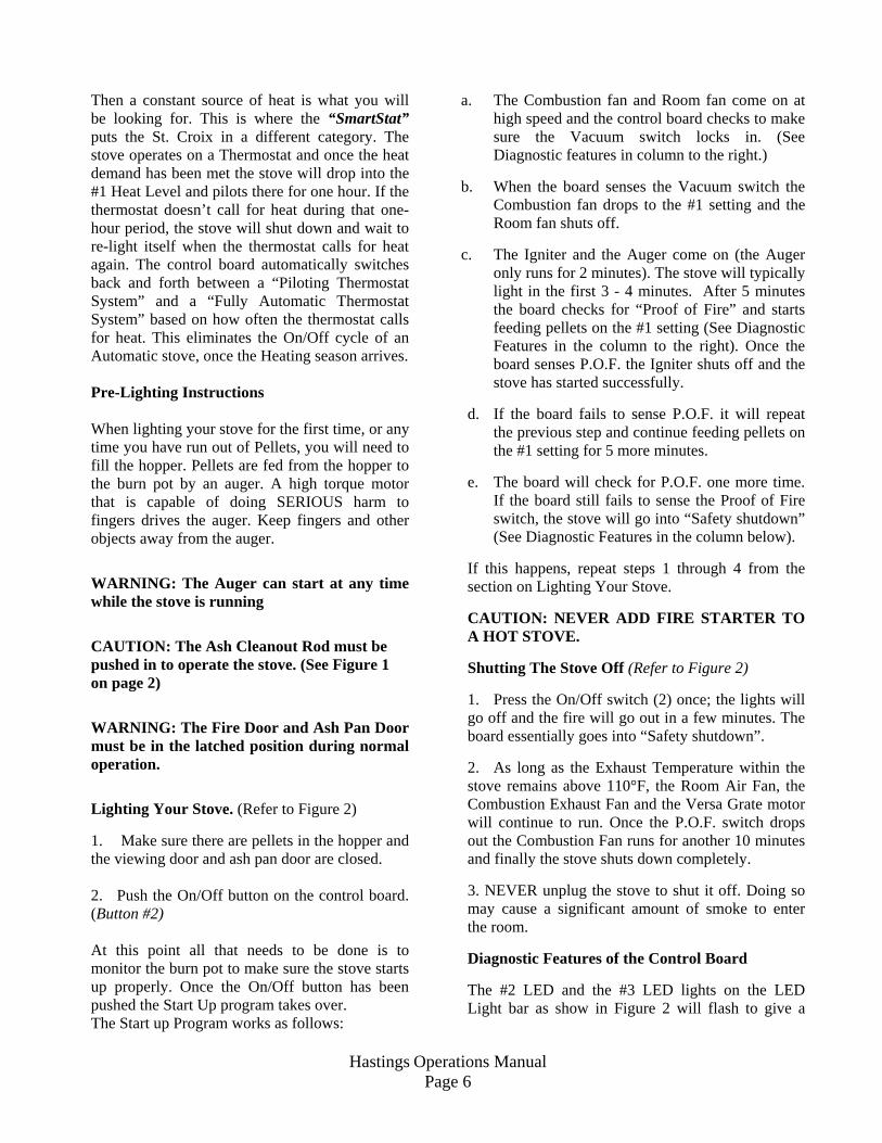
A closer look at the Control Board on page 5, in figure 2 will explain how the board works. There are five buttons labeled 1 through 5, a slide switch labeled 6 and a LED Light bar with 5 Heat Settings. The LED Light bar is also used during the Diagnostic process, see page 6 and 7 for more details. The buttons on the board function as follows: (Refer to Figure 2. The touch pad buttons and Slide Switch are labeled with the white numbers 1 through 6) 1. The Heat Level button (1) will advance the setting between level 1 and 5. Once you reach level 5, it will drop back to level 1. Each level has a LED light to indicate where the board is set. 2. The On/Off button (2) turns the Stove On and Off. It will also reset the board after the board has sensed a problem and is flashing a Diagnostic code.
3. The auger button (3) will allow the customer to manually auger pellets into the burn pot on start up
Hastings Operations Manual Page 5
when needed. This is particularly helpful in priming the Auger Tube when it is empty. 4. The Draft Trim button (4) allows for adjusting the Exhaust fan voltage on Heat Level 1 only. Push the button and the all of the LED Lights in the light bar will flash once. This decreases the Exhaust fan voltage approximately 5 volts below the default setting. Push the button a second time and all of the LED Lights in the light bar will flash twice. This decreases the voltage approximately another 5 volts. Pushing the button a 3rd time will reset the voltage to the default setting. This adjustment is available to fine tune the #1 Heat Level draft setting only. This would only be used in the case the Stove was hooked up to a tall Vertical Chimney (see point 9 on page 18 for more information)
Figure 2
5. The Feed Trim button (5) will allow the Fuel feed rate to be adjusted on Heat Level 1 only.
Heat Level 1 should be seen as the Pilot setting of the Stove, when operating on a Thermostat. Pushing the Feed Trim button (5) will switch between the different adjustments. Heat Level one can be adjusted in the following ways:
a. The first LED only indicates the Normal #1 setting. (1.5 second on time). This is the default setting.
b. The first and fourth LED lights indicate the
#1 Low setting. (1.25 second on time) This will reduce the heat output on the #1 setting. This setting will also create more buildup on the glass. (See point 8 on page 17)
c. The first and fifth LED lights indicate the #1
High setting. (1.75 second on time) This will produce the most heat available on the #1 setting. This is helpful in keeping the glass a little cleaner when burning on low.
The adjustments described in points 4 and 5 remain in effect as long as the unit is plugged in. If the unit gets unplugged or if there is a power failure the settings are lost and the adjustments would need to be reset. Thermostat Function – How does it work? 6. Thermostat Slide Switch. Use this switch to
change the Operations mode between a Manual Mode, T-stat Mode or a fully Automatic “SmartStat” Mode.
Manual Mode – The stove is controlled by the control Board and the operator; no thermostat involved. T-Stat Mode – This is where a thermostat controls the stove, but the stove never shuts down. In this mode the stove will advance to the Heat Level that has been selected when the thermostat calls for heat and drops to the #1 Heat Level and pilots when the thermostat doesn’t call for heat. SmartStat Mode – How does it work? The SmartStat Function on a St. Croix Pellet stove is the way a St. Croix operates as a Fully Automatic stove. A stove operating as a Fully Automatic stove works great when constant heat isn’t needed. The stove lights when heat is needed and shuts off when it isn’t needed. However this is not the way to operate a stove once the Heating Season arrives.
Hastings Operations Manual Page 6
Then a constant source of heat is what you will be looking for. This is where the “SmartStat” puts the St. Croix in a different category. The stove operates on a Thermostat and once the heat demand has been met the stove will drop into the #1 Heat Level and pilots there for one hour. If the thermostat doesn’t call for heat during that one-hour period, the stove will shut down and wait to re-light itself when the thermostat calls for heat again. The control board automatically switches back and forth between a “Piloting Thermostat System” and a “Fully Automatic Thermostat System” based on how often the thermostat calls for heat. This eliminates the On/Off cycle of an Automatic stove, once the Heating season arrives. Pre-Lighting Instructions When lighting your stove for the first time, or any time you have run out of Pellets, you will need to fill the hopper. Pellets are fed from the hopper to the burn pot by an auger. A high torque motor that is capable of doing SERIOUS harm to fingers drives the auger. Keep fingers and other objects away from the auger. WARNING: The Auger can start at any time while the stove is running CAUTION: The Ash Cleanout Rod must be pushed in to operate the stove. (See Figure 1 on page 2) WARNING: The Fire Door and Ash Pan Door must be in the latched position during normal operation. Lighting Your Stove. (Refer to Figure 2) 1. Make sure there are pellets in the hopper and the viewing door and ash pan door are closed. 2. Push the On/Off button on the control board. (Button #2) At this point all that needs to be done is to monitor the burn pot to make sure the stove starts up properly. Once the On/Off button has been pushed the Start Up program takes over. The Start up Program works as follows:
a. The Combustion fan and Room fan come on at high speed and the control board checks to make sure the Vacuum switch locks in. (See Diagnostic features in column to the right.)
b. When the board senses the Vacuum switch the
Combustion fan drops to the #1 setting and the Room fan shuts off.
c. The Igniter and the Auger come on (the Auger
only runs for 2 minutes). The stove will typically light in the first 3 - 4 minutes. After 5 minutes the board checks for “Proof of Fire” and starts feeding pellets on the #1 setting (See Diagnostic Features in the column to the right). Once the board senses P.O.F. the Igniter shuts off and the stove has started successfully.
d. If the board fails to sense P.O.F. it will repeat
the previous step and continue feeding pellets on the #1 setting for 5 more minutes.
e. The board will check for P.O.F. one more time.
If the board still fails to sense the Proof of Fire switch, the stove will go into “Safety shutdown” (See Diagnostic Features in the column below).
If this happens, repeat steps 1 through 4 from the section on Lighting Your Stove. CAUTION: NEVER ADD FIRE STARTER TO A HOT STOVE. Shutting The Stove Off (Refer to Figure 2) 1. Press the On/Off switch (2) once; the lights will go off and the fire will go out in a few minutes. The board essentially goes into “Safety shutdown”. 2. As long as the Exhaust Temperature within the stove remains above 110°F, the Room Air Fan, the Combustion Exhaust Fan and the Versa Grate motor will continue to run. Once the P.O.F. switch drops out the Combustion Fan runs for another 10 minutes and finally the stove shuts down completely. 3. NEVER unplug the stove to shut it off. Doing so may cause a significant amount of smoke to enter the room. Diagnostic Features of the Control Board The #2 LED and the #3 LED lights on the LED Light bar as show in Figure 2 will flash to give a
Hastings Operations Manual Page 7
WARNING: These safety features are designed to protect life and property. Bypassing these features voids all warranties and the safety listing of the stove.
diagnostic code to help in diagnosing problems that may occur. These conditions fall into 2 categories:
a. Heat related issues.
b. Vacuum related issues. The Diagnostic Lights flash as follows: 1. The Proof of Fire switch. This switch will
sense the temperature of the Exhaust rising during start up. If the Exhaust temperature does not reach 110 degrees F, or if during use the temperature drops below 110 degrees F, the Stove will go into “Internal Alarm” and the Auger will quit feeding fuel. Once the stove completes the safety shutdown, the #3 LED will start blinking. (See Figure 2 on Page 5 and point 3 on page 15)
2. The High Limit switch. This sensor will
sense if the unit reaches temperatures that are too high for normal operation. If this happens the Auger will quit feeding and the #2 and #3 LED lights will flash simultaneously. (See Figure 2 on Page 5 and point 4 on page 16)
3. The Vacuum Switch - For the stove to
operate, the Firebox needs to be sealed. During the first 30 seconds after the stove has been turned on the Control Board will check if the switch senses negative pressure (Vacuum) in the Firebox of the stove. If there is no negative pressure, the stove will shut down and the #2 LED will start blinking. (See Figure 2 on Page 5 and point 2 on page 15).
“Power Reset”. If the board becomes unresponsive you must unplug the stove, wait 10 seconds and plug the stove back in to reset the board. “Internal Alarm”. When the control board becomes unresponsive, the control board is in Internal Alarm. The control board has sensed one of the Safety sensors. This may cause the stove to go out. In some cases, after waiting approximately 45 seconds the stove will start responding to the control board again. Many times, the cause of this is a change in the vacuum inside the stove. This may be caused by excessive wind, opening the Firebox door or opening the
Ash Pan door. The control board will monitor the vacuum switch and resume normal operation if the vacuum returns to normal. Safety Features 1. ”High Limit” switch”, an overheat safety
switch will shut off the fuel feed if the Stove reaches temperatures above normal operating temperature. This is a “Normally Closed” switch and is part of the Fan limit control. If the High limit switch trips several times, the problem in the Stove must be diagnosed before the Stove is put back in service, (Defective Room Fan, dirty Room Fan, defective Fan Limit Control or possibly a bad Control Board)
2. Proof of Fire switch also called the P.O.F. This
senses the temperature rise in the exhaust system. The switch is “Normally Open” and closes the circuit at 110 degrees. The Stove will shut down if temperatures above 110 degrees F are not sensed during start up or if the temperature drops below 110 degrees during normal operation.
3. Vacuum switch also called the Negative
pressure switch. When the stove is turned on the Exhaust fan will create a negative pressure in the firebox. The control board continually checks to see if Negative Pressure (vacuum) is present during operation of the Stove. If the exhaust venting system becomes clogged or obstructed, the firebox door or ash pan door are left open or the exhaust fan quits working the control board will go into “Safety shutdown”. There is a 60 second window to allow for cleaning the glass and removing the clinker before then Stove shuts down. This is sufficient for the Daily Maintenance
The St. Croix Pellet Stove has been Safety Tested by an accredited, independent laboratory.
Hastings Operations Manual Page 8
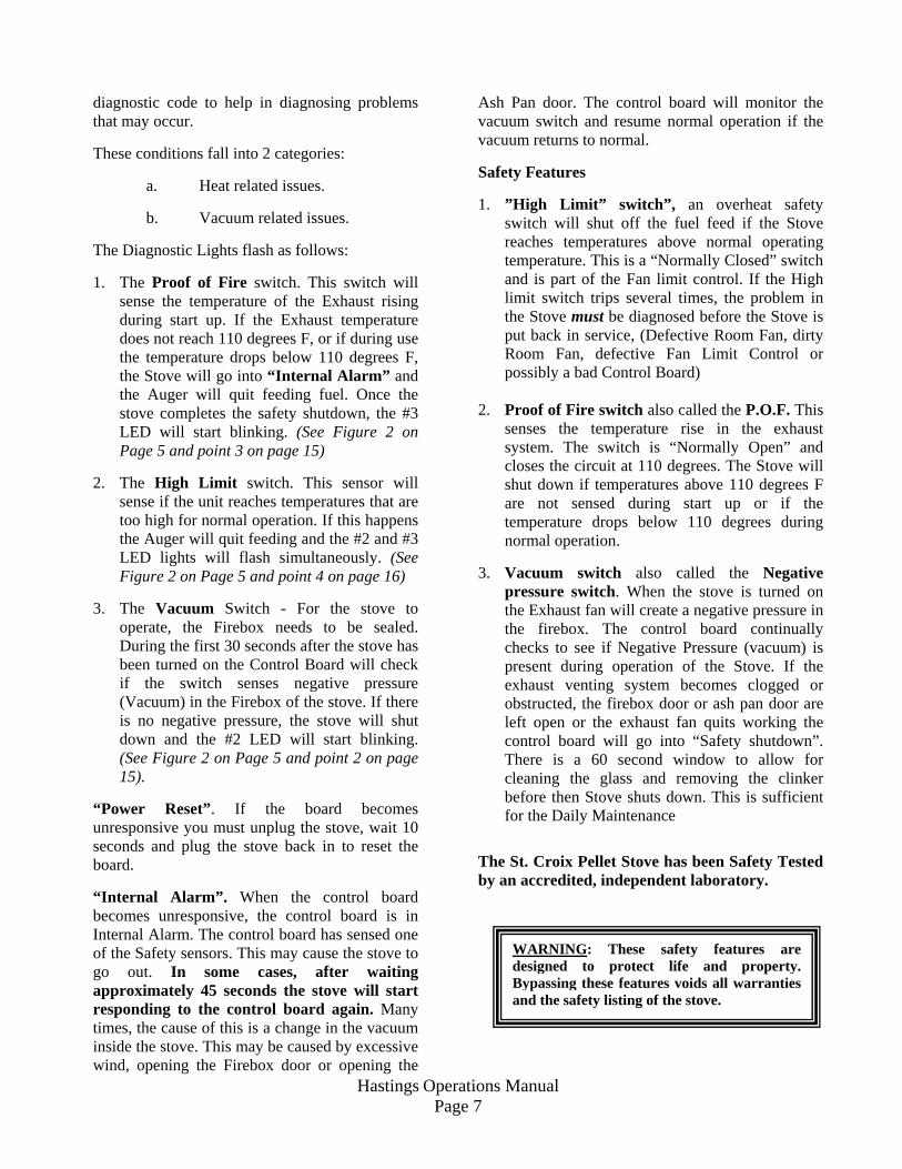
THERMOSTAT WIRE
TERMINAL
DAMPER
Combustion Air Damper
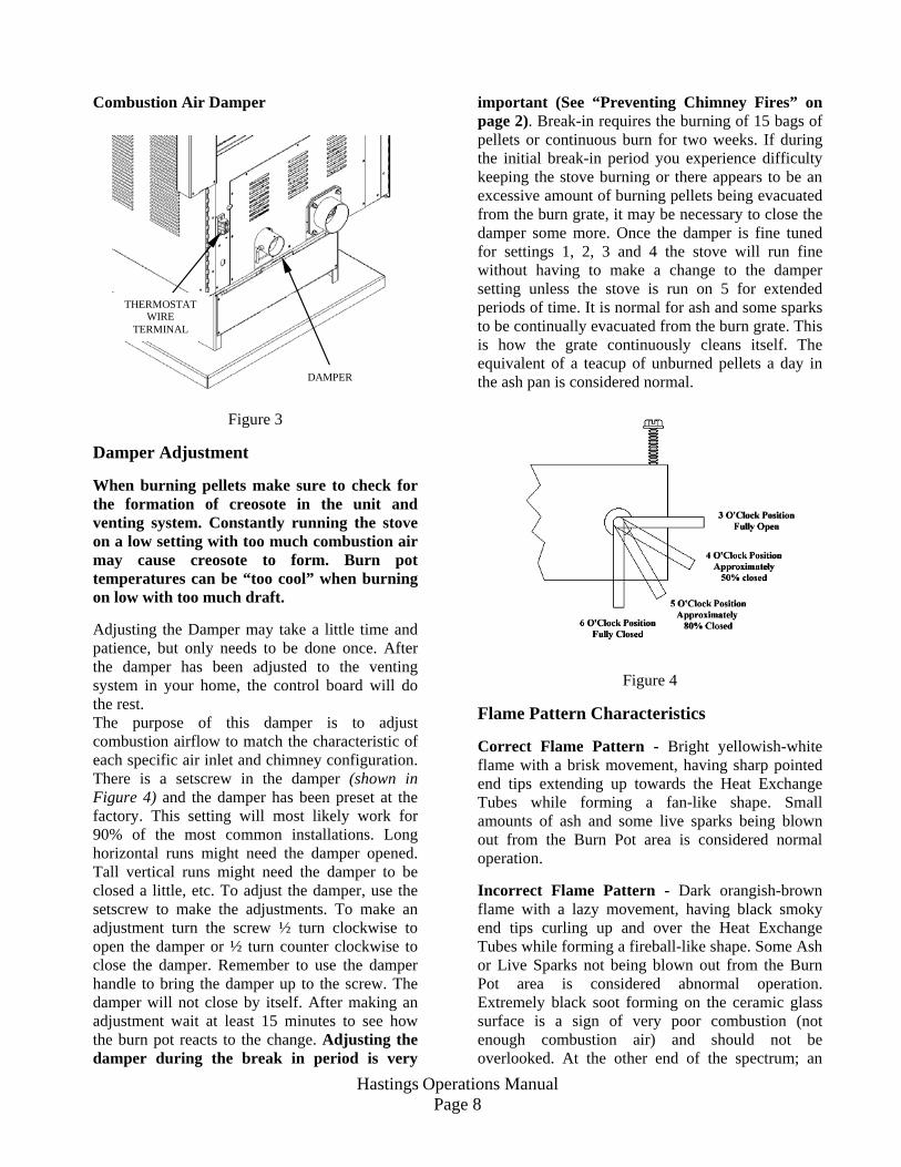
Figure 3 Damper Adjustment When burning pellets make sure to check for the formation of creosote in the unit and venting system. Constantly running the stove on a low setting with too much combustion air may cause creosote to form. Burn pot temperatures can be “too cool” when burning on low with too much draft. Adjusting the Damper may take a little time and patience, but only needs to be done once. After the damper has been adjusted to the venting system in your home, the control board will do the rest. The purpose of this damper is to adjust combustion airflow to match the characteristic of each specific air inlet and chimney configuration. There is a setscrew in the damper (shown in Figure 4) and the damper has been preset at the factory. This setting will most likely work for 90% of the most common installations. Long horizontal runs might need the damper opened. Tall vertical runs might need the damper to be closed a little, etc. To adjust the damper, use the setscrew to make the adjustments. To make an adjustment turn the screw ½ turn clockwise to open the damper or ½ turn counter clockwise to close the damper. Remember to use the damper handle to bring the damper up to the screw. The damper will not close by itself. After making an adjustment wait at least 15 minutes to see how the burn pot reacts to the change. Adjusting the damper during the break in period is very
important (See “Preventing Chimney Fires” on page 2). Break-in requires the burning of 15 bags of pellets or continuous burn for two weeks. If during the initial break-in period you experience difficulty keeping the stove burning or there appears to be an excessive amount of burning pellets being evacuated from the burn grate, it may be necessary to close the damper some more. Once the damper is fine tuned for settings 1, 2, 3 and 4 the stove will run fine without having to make a change to the damper setting unless the stove is run on 5 for extended periods of time. It is normal for ash and some sparks to be continually evacuated from the burn grate. This is how the grate continuously cleans itself. The equivalent of a teacup of unburned pellets a day in the ash pan is considered normal.
Figure 4 Flame Pattern Characteristics Correct Flame Pattern - Bright yellowish-white flame with a brisk movement, having sharp pointed end tips extending up towards the Heat Exchange Tubes while forming a fan-like shape. Small amounts of ash and some live sparks being blown out from the Burn Pot area is considered normal operation. Incorrect Flame Pattern - Dark orangish-brown flame with a lazy movement, having black smoky end tips curling up and over the Heat Exchange Tubes while forming a fireball-like shape. Some Ash or Live Sparks not being blown out from the Burn Pot area is considered abnormal operation. Extremely black soot forming on the ceramic glass surface is a sign of very poor combustion (not enough combustion air) and should not be overlooked. At the other end of the spectrum; an
Hastings Operations Manual Page 9
extremely brisk flame which blows large pieces of live coal out from the Burn Pot area and causes stubborn shiny black build-up on the glass (too much combustion air) is also considered undesirable. If you experience problems adjusting the stove during the Break-In Period, contact your dealer. MAINTAINING THE STOVE - The stove requires a minimum amount of daily maintenance. Required maintenance depends largely upon the quality of pellet fuel burned and the rate of burn. The amount of daily maintenance will increase if fuel quality decreases and/or the burning rate of pellets increases.
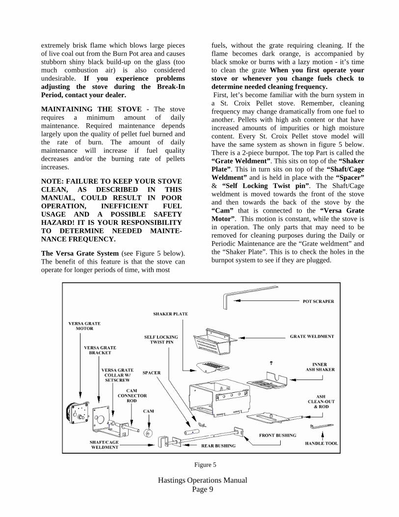
NOTE: FAILURE TO KEEP YOUR STOVE CLEAN, AS DESCRIBED IN THIS MANUAL, COULD RESULT IN POOR OPERATION, INEFFICIENT FUEL USAGE AND A POSSIBLE SAFETY HAZARD! IT IS YOUR RESPONSIBILITY TO DETERMINE NEEDED MAINTE-NANCE FREQUENCY. The Versa Grate System (see Figure 5 below). The benefit of this feature is that the stove can operate for longer periods of time, with most
fuels, without the grate requiring cleaning. If the flame becomes dark orange, is accompanied by black smoke or burns with a lazy motion - it’s time to clean the grate When you first operate your stove or whenever you change fuels check to determine needed cleaning frequency. First, let’s become familiar with the burn system in a St. Croix Pellet stove. Remember, cleaning frequency may change dramatically from one fuel to another. Pellets with high ash content or that have increased amounts of impurities or high moisture content. Every St. Croix Pellet stove model will have the same system as shown in figure 5 below. There is a 2-piece burnpot. The top Part is called the “Grate Weldment”. This sits on top of the “Shaker Plate”. This in turn sits on top of the “Shaft/Cage Weldment” and is held in place with the “Spacer” & “Self Locking Twist pin”. The Shaft/Cage weldment is moved towards the front of the stove and then towards the back of the stove by the “Cam” that is connected to the “Versa Grate Motor”. This motion is constant, while the stove is in operation. The only parts that may need to be removed for cleaning purposes during the Daily or Periodic Maintenance are the “Grate weldment” and the “Shaker Plate”. This is to check the holes in the burnpot system to see if they are plugged.
Figure 5
Hastings Operations Manual Page 10
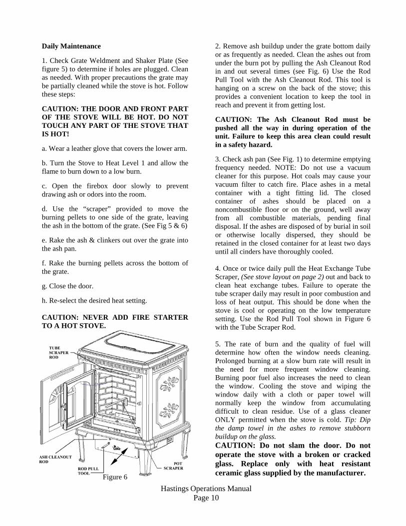
Daily Maintenance 1. Check Grate Weldment and Shaker Plate (See figure 5) to determine if holes are plugged. Clean as needed. With proper precautions the grate may be partially cleaned while the stove is hot. Follow these steps: CAUTION: THE DOOR AND FRONT PART OF THE STOVE WILL BE HOT. DO NOT TOUCH ANY PART OF THE STOVE THAT IS HOT! a. Wear a leather glove that covers the lower arm. b. Turn the Stove to Heat Level 1 and allow the flame to burn down to a low burn. c. Open the firebox door slowly to prevent drawing ash or odors into the room. d. Use the “scraper” provided to move the burning pellets to one side of the grate, leaving the ash in the bottom of the grate. (See Fig 5 & 6) e. Rake the ash & clinkers out over the grate into the ash pan. f. Rake the burning pellets across the bottom of the grate. g. Close the door. h. Re-select the desired heat setting. CAUTION: NEVER ADD FIRE STARTER TO A HOT STOVE.
Figure 6
2. Remove ash buildup under the grate bottom daily or as frequently as needed. Clean the ashes out from under the burn pot by pulling the Ash Cleanout Rod in and out several times (see Fig. 6) Use the Rod Pull Tool with the Ash Cleanout Rod. This tool is hanging on a screw on the back of the stove; this provides a convenient location to keep the tool in reach and prevent it from getting lost. CAUTION: The Ash Cleanout Rod must be pushed all the way in during operation of the unit. Failure to keep this area clean could result in a safety hazard. 3. Check ash pan (See Fig. 1) to determine emptying frequency needed. NOTE: Do not use a vacuum cleaner for this purpose. Hot coals may cause your vacuum filter to catch fire. Place ashes in a metal container with a tight fitting lid. The closed container of ashes should be placed on a noncombustible floor or on the ground, well away from all combustible materials, pending final disposal. If the ashes are disposed of by burial in soil or otherwise locally dispersed, they should be retained in the closed container for at least two days until all cinders have thoroughly cooled. 4. Once or twice daily pull the Heat Exchange Tube Scraper, (See stove layout on page 2) out and back to clean heat exchange tubes. Failure to operate the tube scraper daily may result in poor combustion and loss of heat output. This should be done when the stove is cool or operating on the low temperature setting. Use the Rod Pull Tool shown in Figure 6 with the Tube Scraper Rod. 5. The rate of burn and the quality of fuel will determine how often the window needs cleaning. Prolonged burning at a slow burn rate will result in the need for more frequent window cleaning. Burning poor fuel also increases the need to clean the window. Cooling the stove and wiping the window daily with a cloth or paper towel will normally keep the window from accumulating difficult to clean residue. Use of a glass cleaner ONLY permitted when the stove is cold. Tip: Dip the damp towel in the ashes to remove stubborn buildup on the glass. CAUTION: Do not slam the door. Do not operate the stove with a broken or cracked glass. Replace only with heat resistant ceramic glass supplied by the manufacturer.
Hastings Operations Manual Page 11
6. Burn the stove at the HI fuel setting for at least 20 to 30 minutes each day. This helps keep the window, firebrick and firebox area clean. A daily high burn also aids in maintaining the overall efficiency and performance of the stove. Periodic Maintenance CAUTION: Periodic maintenance should only be done while the stove is shut off and cold. 1. Empty the ash pan when it appears full. This
may range from 1 to 2 times a week in the Hastings. The frequency of cleaning the ash pan will depend on the quality and amount of pellets being used. Carefully check to make sure the ash pan door is tightly closed after each opening.
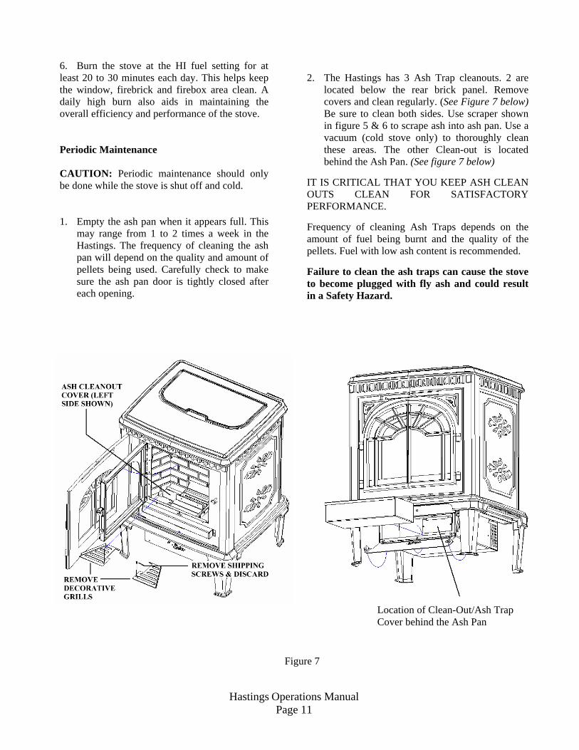
2. The Hastings has 3 Ash Trap cleanouts. 2 are
located below the rear brick panel. Remove covers and clean regularly. (See Figure 7 below) Be sure to clean both sides. Use scraper shown in figure 5 & 6 to scrape ash into ash pan. Use a vacuum (cold stove only) to thoroughly clean these areas. The other Clean-out is located behind the Ash Pan. (See figure 7 below)
IT IS CRITICAL THAT YOU KEEP ASH CLEAN OUTS CLEAN FOR SATISFACTORY PERFORMANCE.
Frequency of cleaning Ash Traps depends on the amount of fuel being burnt and the quality of the pellets. Fuel with low ash content is recommended. Failure to clean the ash traps can cause the stove to become plugged with fly ash and could result in a Safety Hazard.
Figure 7
Location of Clean-Out/Ash Trap Cover behind the Ash Pan
Hastings Operations Manual Page 12
3. Clean burn grate holes at least weekly.
Remove the burn grate and use a small metal object to clean out plugged holes. (See fig. 5 on page 9.)
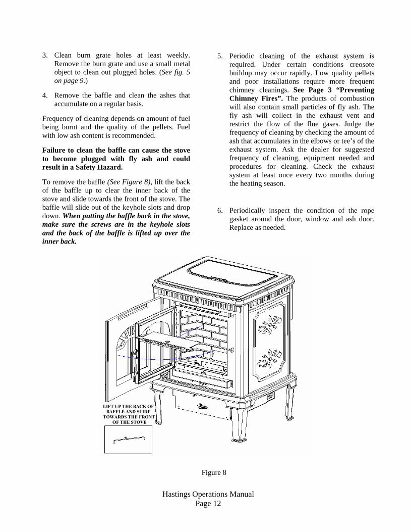
4. Remove the baffle and clean the ashes that
accumulate on a regular basis. Frequency of cleaning depends on amount of fuel being burnt and the quality of the pellets. Fuel with low ash content is recommended. Failure to clean the baffle can cause the stove to become plugged with fly ash and could result in a Safety Hazard. To remove the baffle (See Figure 8), lift the back of the baffle up to clear the inner back of the stove and slide towards the front of the stove. The baffle will slide out of the keyhole slots and drop down. When putting the baffle back in the stove, make sure the screws are in the keyhole slots and the back of the baffle is lifted up over the inner back.
5. Periodic cleaning of the exhaust system is
required. Under certain conditions creosote buildup may occur rapidly. Low quality pellets and poor installations require more frequent chimney cleanings. See Page 3 “Preventing Chimney Fires”. The products of combustion will also contain small particles of fly ash. The fly ash will collect in the exhaust vent and restrict the flow of the flue gases. Judge the frequency of cleaning by checking the amount of ash that accumulates in the elbows or tee’s of the exhaust system. Ask the dealer for suggested frequency of cleaning, equipment needed and procedures for cleaning. Check the exhaust system at least once every two months during the heating season.
6. Periodically inspect the condition of the rope gasket around the door, window and ash door. Replace as needed.
Figure 8
Hastings Operations Manual Page 13
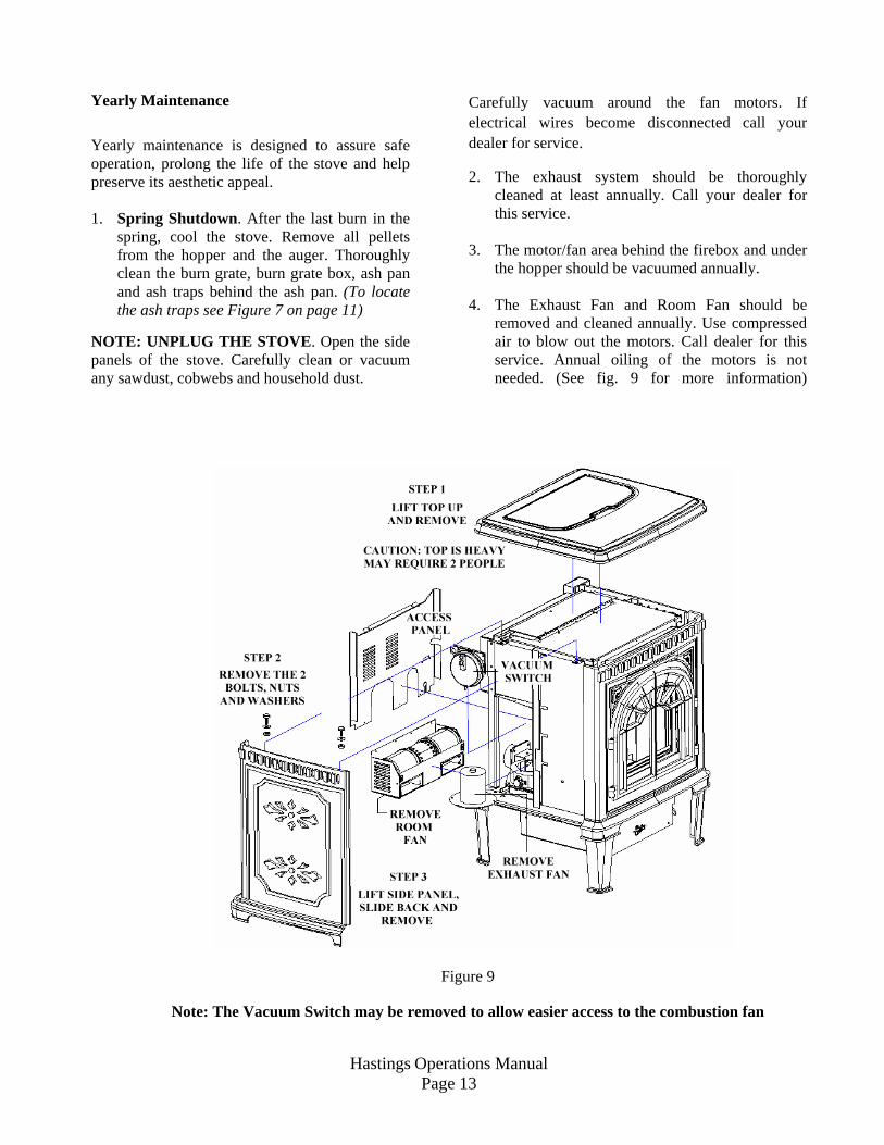
Yearly Maintenance Yearly maintenance is designed to assure safe operation, prolong the life of the stove and help preserve its aesthetic appeal. 1. Spring Shutdown. After the last burn in the
spring, cool the stove. Remove all pellets from the hopper and the auger. Thoroughly clean the burn grate, burn grate box, ash pan and ash traps behind the ash pan. (To locate the ash traps see Figure 7 on page 11)
NOTE: UNPLUG THE STOVE. Open the side panels of the stove. Carefully clean or vacuum any sawdust, cobwebs and household dust.
Carefully vacuum around the fan motors. If electrical wires become disconnected call your dealer for service.
2. The exhaust system should be thoroughly cleaned at least annually. Call your dealer for this service.
3. The motor/fan area behind the firebox and under
the hopper should be vacuumed annually. 4. The Exhaust Fan and Room Fan should be
removed and cleaned annually. Use compressed air to blow out the motors. Call dealer for this service. Annual oiling of the motors is not needed. (See fig. 9 for more information)
Figure 9
Note: The Vacuum Switch may be removed to allow easier access to the combustion fan