Embed Size (px)
Citation preview
Louisiana State UniversityLSU Digital Commons
LSU Agricultural Experiment Station Reports LSU AgCenter
1963
Harvesting sweet potatoes in LouisianaWiley Davis Poole
Follow this and additional works at: http://digitalcommons.lsu.edu/agexp
This Article is brought to you for free and open access by the LSU AgCenter at LSU Digital Commons. It has been accepted for inclusion in LSUAgricultural Experiment Station Reports by an authorized administrator of LSU Digital Commons. For more information, please [email protected].
Recommended CitationPoole, Wiley Davis, "Harvesting sweet potatoes in Louisiana" (1963). LSU Agricultural Experiment Station Reports. 578.http://digitalcommons.lsu.edu/agexp/578
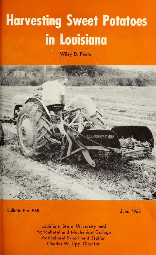
Bulletin No. 568 June 1963
Louisiana State University and
Agricultural and Mechanical College
Agricultural Experinnent Station
Charles W. Upp, Director
Table of Contents
Acknowledgements 2
Introduction 3
Removing the Vines 3
Harvesting 9
Plow Type Diggers 9
Irish Potato Diggers 12
Short-Bed Tractor Mounted Diggers 13
Sweet Potato Harvesters 15
Acknowledgements
Appreciation is expressed to Dr. Julian C. Miller and Dr. Teme P.
Hernandez of the Department of Horticulture and Landscape Archi-
tecture, Louisiana Agricultural Experiment Station, Louisiana State
University, for helping in the planning and providing of sweet potatoes
for testing of much of the equipment, and for reviewing of the manu-
script. Gratitude is also extended to Professor Harold T. Barr of the
Department of Agricultural Engineering, Louisiana Agricultural Experi-
ment Station, Louisiana State University, for providing facilities and
helpful guidance for this work. Appreciation is also expressed to the
many farmers who cooperated by providing sweet potato fields for the
operation and testing of these machines. Gratitude is also extended to
Mr. S. L. Gianfala of Church Point, Louisiana, for building and helping
with the field testing of one type of harvester.
2
Harvesting Sweet Potatoes in Louisiana
Wiley D. Poole
Agricultural Engineering Department
Introduction
Mechanical handling and harvesting of sweet potatoes offer the best
possible solution for reducing the cost of production of this crop, which
is the most important vegetable crop in the South and the second most
important vegetable crop in the United States.
Farmers with small acreages of sweet potatoes have not been able to
mechanize because of the high cost involved. Therefore, the trend has
been to concentrate sweet potato production into larger farm units which
can justify mechanization. The best way to reduce the cost of production
is to use mechanical equipment wherever possible. Larger acreage per
farm unit justifies the use of power equipment such as tractor plows,
transplanters, tractor cultivators and mechanical harvesters.
With the exception of mechanical harvesters, much of the machinery
developed for other crops could be adapted to sweet potato culture
and, since harvesting requires more man-hours of labor than all other
operations combined, development design and research have been di-
rected toward a suitable machine for harvesting sweet potatoes.
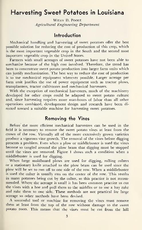
Removing the Vines
Before the more efficient mechanical harvesters can be used in the
field it is necessary to remove the sweet potato vines at least from the
crown of the row. Virtually all of the more extensively grown varieties
produce a vigorous vine growth. The removal of the vines before digging
presents a problem. Even when a plow or middlebuster is used the vines
become so tangled around the plow beam that digging must be stopped
until the vines are removed. Figure 1 shows such a condition when a
middlebuster is used for digging.
When large moldboard plows are used for digging, rolling colters
or a stationary knife attached to the plow beam can be used since the
plow will be set to run off to one side of the row. When a middlebuster
is used the colter is usually run on the center of the row. This results
in many potatoes being cut by the colter, so this practice is not recom-
mended. Where the acreage is small it has been common practice to cut
the vines with a hoe and pull them to the middles or to use a hay rake
and rake them to one side. These methods are not practical for large
acreage so other methods have been devised.
A successful tool or machine for removing the vines must removethem at least from the top of the row without damage to the sweetpotato roots. This means that the vines must be cut from the hill
3
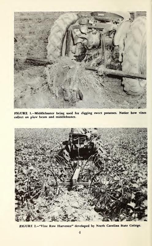
FIGURE 1.—Middlebuster being used for digging sweet potatoes. Notice how vines
collect on plow beam and middlebuster.
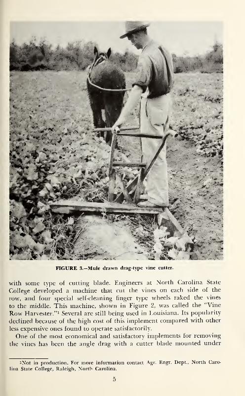
FIGURE 3.—Mule drawn drag-type vine cutter.
with some type of cutting blade. Engineers at North Carolina State
College developed a machine that cut the vines on each side of the
row, and four special self-cleaning finger type wheels raked the vines
to the middle. This machine, shown in Figure 2, was called the "Vine
Row Harvester."! Several are still being used in Louisiana. Its popularity
declined because of the high cost of this implement compared with other
less expensive ones found to operate satisfactorily.
One of the most economical and satisfactory implements for removing
the vines has been the angle drag with a cutter blade mounted under
iNot in production. For more information contact Agr. Engr. Dept., North Caro-
lina State College, Raleigh, North Carolina.
5
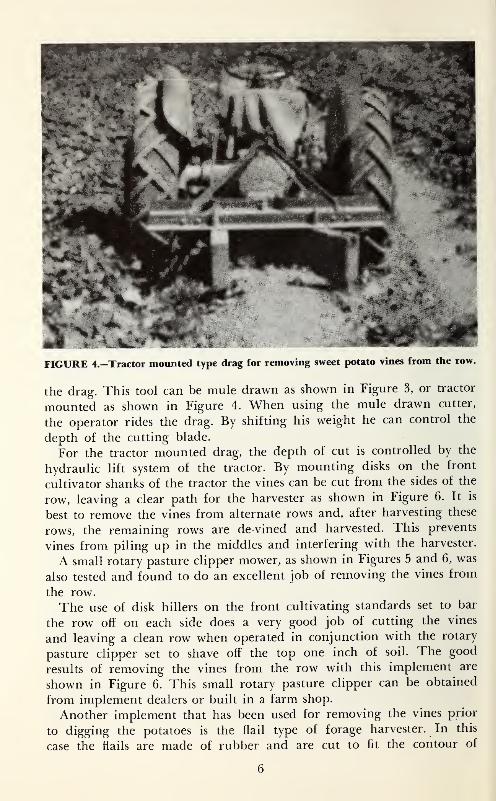
FIGURE 4.—Tractor mounted type drag for removing sweet potato vines from the row.
the drag. This tool can be mule drawn as shown in Figure 3, or tractor
mounted as shown in Figure 4. When using the mule drawn cutter,
the operator rides the drag. By shifting his weight he can control the
depth of the cutting blade.
For the tractor mounted drag, the depth of cut is controlled by the
hydraulic lift system of the tractor. By mounting disks on the front
cultivator shanks of the tractor the vines can be cut from the sides of the
row, leaving a clear path for the harvester as shown in Figure 6. It is
best to remove the vines from alternate rows and, after harvesting these
rows, the remaining rows are de-vined and harvested. This prevents
vines from, piling up in the middles and interfering with the harvester.
A small rotary pasture clipper mower, as shown in Figures 5 and 6, was
also tested and found to do an excellent job of removing the vines from
the row.
The use of disk hillers on the front cultivating standards set to bar
the row off on each side does a very good job of cutting the vines
and leaving a clean row when operated in conjunction with the rotary
pasture clipper set to shave off the top one inch of soil. The good
results of removing the vines from the row with this implement are
shown in Figure 6. This small rotary pasture clipper can be obtained
from implement dealers or built in a farm shop.
Another implement that has been used for removing the vines prior
to digging the potatoes is the flail type of forage harvester. In this
case the flails are made of rubber and are cut to fit the contour of
6
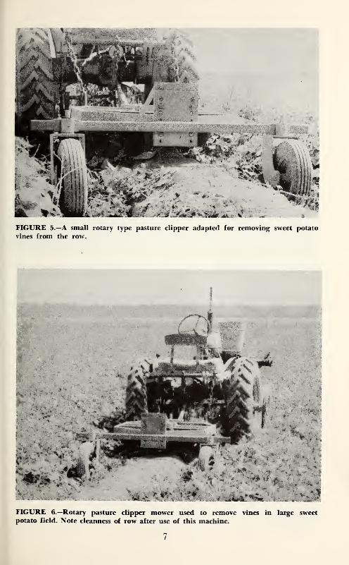
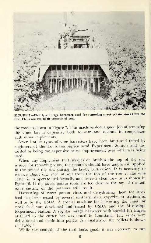
FIGURE 7.—Flail type forage harvester used for removing sweet potato vines from the
row. Flails are cut to fit contour of row.
the rows as shown in Figure 7. This machine does a good job of removing
the vines but is expensive both to own and operate in comparison
with other implements.
Several other types of vine harvesters have been built and tested by
engineers of the Louisiana Agricultural Experiment Station and dis-
carded as being too expensive or no improvement over what was being
used.
When any implement that scrapes or brushes the top of the row
is used for removing vines, the potatoes should have ample soil applied
to the top of the row during the lay-by cultivation. It is necessary to
remove about one inch of soil from the top of the row if the vine
cutter is to operate satisfactorily and leave a clean row as is shown in
Figure 6. If the sweet potato roots are too close to the top of the soil
some cutting of the potatoes will result.
Harvesting of sweet potato vines and dehydrating them for stock
feed has been tested by several southern state experiment stations as
well as by the USDA. A special machine for harvesting the vines for
stock feed was developed and tested by USDA and the Mississippi
Experiment Station. A regular forage harvester with special lift fingers
attached to the cutter bar was tested in Louisiana. The vines were
dehydrated and made into pellets. An analysis of the pellets is shown
in Table I.
While the analysis of the feed looks good, it was necessary to run
8
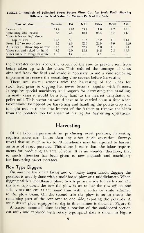
TABLE I.—Analysis of Pelletized Sweet Potato Vines Cut for Stock Feed, Showing
Difference in Feed Value for Various Parts of the Vine
Part of vine Protein Fat NFE Fiber Moist. Ash
14.9 2.93 •JJ.J 11.6 10.8
Vine only (no leaves) 3.8 2.6 48.1 25.5 5.7 14.0
Vines & leaves li/^" above
top of row 12.5 3.1 51.8 15.2 6.1 11.1
From I1/2" to top of row 3.7 2.9 52.0 26.5 5.6 9.25
All vines 1" above top of row 13.3 2.9 52.5 15.8 6.1 9.1
Vines cut and raked by hand 13.3 2.0 33.4 24.5 7.3 19.6
Vines cut with forage harvester 11.0 3.7 17.7
the harvester cutter above the crown of the row to prevent soil frombeing taken up with the vines. This reduced the tonnage of vines
obtained from the field and made it necessary to use a vine removingimplement to remove the remaining vine crowns before harvesting.
There are several reasons why the harvesting of the vines for
stock feed prior to digging has never become popular with farmers.
It requires special machinery and wagons for harvesting and handling.
In many cases it would be a long haul to the nearest dehydrator or
pellet mill. This operation would have to be carried on at a time whenlabor would be needed for harvesting and handling the potato crop andit might not be to the best interest of the farmer to remove the vines
from the potatoes too far ahead of his regular harvesting operations.
Harvesting
Of all labor requirements in producing sweet potatoes, harvesting
requires more man hours than any other single operation. Surveys
reveal that as much as 65 to 70 man-hours may be required to harvest
an acre of sweet potatoes. This alone is more than the labor require-
ments for producing an acre of corn. It is no wonder, therefore, that
so much attention has been given to new methods and machineryfor harvesting sweet potatoes.
Plow Type Diggers
On most of the small farms and on many larger farms, digging the
potatoes is usually done with a moldboard plow or a middlebuster. Whendigging with a moldboard plow, two trips are made for each row. Onthe first trip down the row the plow is set to bar the row off on oneside, vines are cut at the same time with a colter or knife attached
to the plow beam. On the second trip the plow is set to throw the
remaining part of the row over to one side, exposing the potatoes. Amule drawn plow equipped to dig in this manner is shown in Figure 8.
A tractor mounted plow having a portion of the moldboard section
cut away and replaced with rotary type spiral slats is shown in Figure
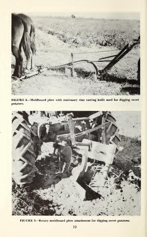
FIGURE 8.—Moldboard plow with stationary vine cutting knife used for digging sweet
potatoes.
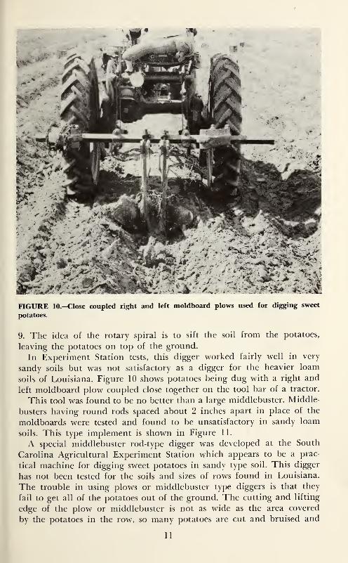
FIGURE 10.—Close coupled right and left moldboard plows used for digging sweet
potatoes.
9. The idea of the rotary spiral is to sift the soil from the potatoes,
leaving the potatoes on top of the ground.
In Experiment Station tests, this digger worked fairly well in very
sandy soils but was not satisfactory as a digger for the heavier loam
soils of Louisiana. Figure 10 shows potatoes being dug with a right and
left moldboard plow coupled close together on the tool bar of a tractor.
This tool was found to be no better than a large middlebuster. Middle-
busters having round rods spaced about 2 inches apart in place of the
moldboards were tested and found to be unsatisfactory in sandy loam
soils. This type implement is shown in Figure 11.
A special middlebuster rod-type digger was developed at the South
Carolina Agricultural Experiment Station which appears to be a prac-
tical machine for digging sweet potatoes in sandy type soil. This digger
has not been tested for the soils and sizes of rows found in Louisiana.
The trouble in using plows or middlebuster type diggers is that they
fail to get all of the potatoes out of the ground. The cutting and lifting
edge of the plow or middlebuster is not as wide as the area covered
by the potatoes in the row, so many potatoes are cut and bruised and
11
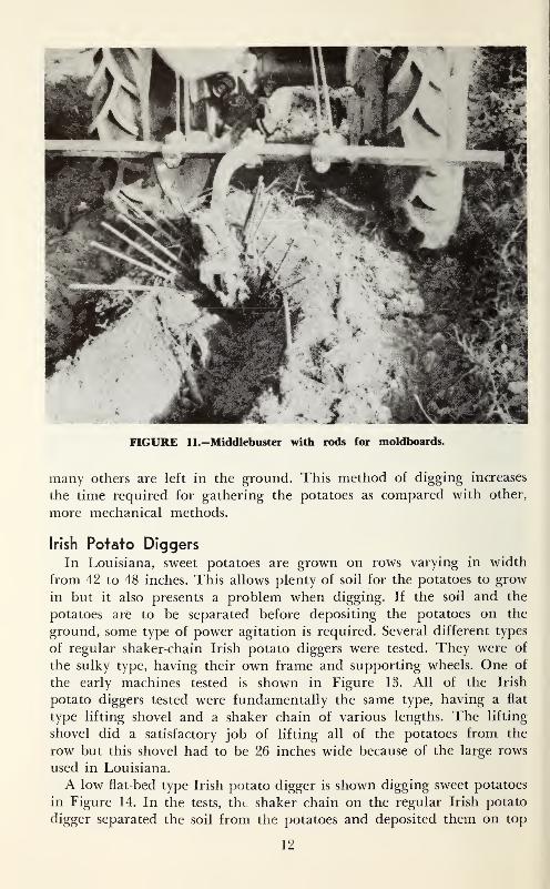
FIGURE 11.—Middlebuster with rods for moldboards.
many others are left in the ground. This method of digging increases
the time required for gathering the potatoes as compared with other,
more mechanical methods.
Irish Potato Diggers
In Louisiana, sweet potatoes are grown on rows varying in width
from 42 to 48 inches. This allows plenty of soil for the potatoes to grow
in but it also presents a problem when digging. If the soil and the
potatoes are to be separated before depositing the potatoes on the
ground, some type of power agitation is required. Several different types
of regular shaker-chain Irish potato diggers were tested. They were of
the sulky type, having their own frame and supporting wheels. One of
the early machines tested is shown in Figure 13. All of the Irish
potato diggers tested were fundamentally the same type, having a flat
type lifting shovel and a shaker chain of various lengths. The lifting
shovel did a satisfactory job of lifting all of the potatoes from the
row but this shovel had to be 26 inches wide because of the large rows
used in Louisiana.
A low flat-bed type Irish potato digger is shown digging sweet potatoes
in Figure 14. In the tests, tht shaker chain on the regular Irish potato
digger separated the soil from the potatoes and deposited them on top
12
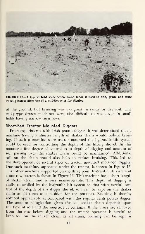
FIGURE 12.—A typical field scene where hand labor is used to find, grade and crate
sweet potatoes after use of a middlebuster for digging.
o£ the ground, but bruising was too great in sandy or dry soil. Thesulky-type drawn machines were also difficult to maneuver in small
fields having narrow turn rows.
Short-Bed Tractor Mounted Diggers
From experiments with Irish potato diggers it was determined that a
machine having a shorter length of shaker chain would reduce bruis-
ing. If such a machine were tractor mounted the hydraulic lift system
could be used for controlling the depth of the lifting shovel. In this
manner a fine degree of control as to depth of digging and amount of
soil passing over the shaker chain could be maintained. Additional
soil on the chain would also help to reduce bruising. This led to
the development of several types of tractor mounted short-bed diggers.
One such machine, supported under the tractor, is shown in Figure 15.
Another machine, supported on the three point hydraulic lift system of
a one-row tractor, is shown in Figure 16. This machine has a short length
of shaker chain and is very maneuverable. The depth of digging is
easily controlled by the hydraulic lift system so that with careful con-
trol of the depth of the digger shovel, soil can be kept on the shaker
chain at all times as a cushion for the potatoes. Bruising is thereby
reduced appreciably as compared with the regular Irish potato digger.
The amount of agitation given the soil shaker chain depends uponthe type of soil and the moisture it contains. If the vines are removedfrom the row before digging and the tractor operator is careful to
keep soil on the shaker chain at all times, bruising can be kept as
13
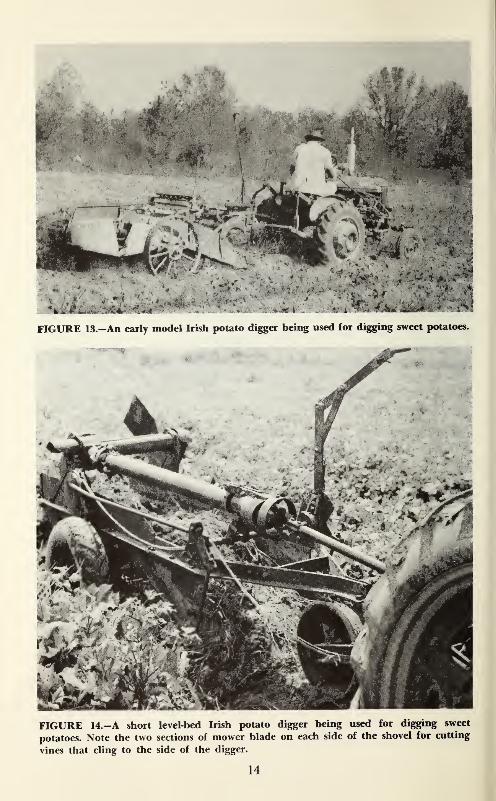
FIGURE 14.-A short level-bed Irish potato digger being used for digging sweet
potatoes. Note the two sections of mower blade on each side of the shovel for cutting
vines that cling to the side of the digger.
14
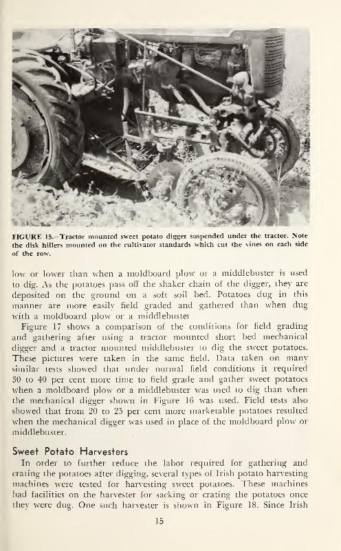
FIGURE 15—Tractor mounted sweet potato digger suspended under the tractor. Note
the disk hillers mounted on the cultivator standards which cut the vines on each side
of the row.
lo^\' or loAver than ^vhen a moldboarcl plo^v or a middlebuster is used
to dig. As the potatoes pass off the shaker chain of the digger, thev are
deposited on the ground on a soft soil bed. Potatoes dug in this
manner are more easih' field graded and gathered than ^vhen dug
with a moldboard plo^v or a middlebustei
Figure 17 shows a comparison of the conditions for field grading
and gathering after using a tractor mounted short bed mechanical
digger and a tractor mounted middlebuster to dig the sweet potatoes.
These pictures were taken in the same field. Data taken on mam-similar tests sho^ved that under normal field conditions it required
30 to 40 per cent more time to field grade and gather sweet potatoes
^\'hen a moldboard plow or a middlebuster was used to dig than whenthe mechanical digger sho^vn in Figin^e 16 -^vas used. Field tests also
showed that from 20 to 25 per cent more marketable potatoes resulted
^vhen the mechanical digger was used in place of the moldboard plo^v or
middlebuster.
Sweet Potato Harvesters
In order to further reduce the labor required for gathering and
crating the potatoes after digging, several tvpes of Irish potato harvesting
machines were tested for harvesting s^veet potatoes. These machines
had facilities on the harvester for sacking or crating the potatoes once
they were dug. One such harvester is shown in Figure 18. Since Irish
15
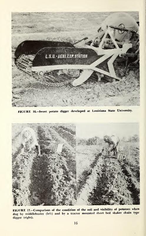
FIGURE 16.—Sweet potato digger developed at Louisiana State University.
FIGURE 17.-Comparison of the condition of the soil and visibility off potatoes when
dug by middlebuster (left) and by a tractor mounted short bed shaker chain type
digger (right).
16
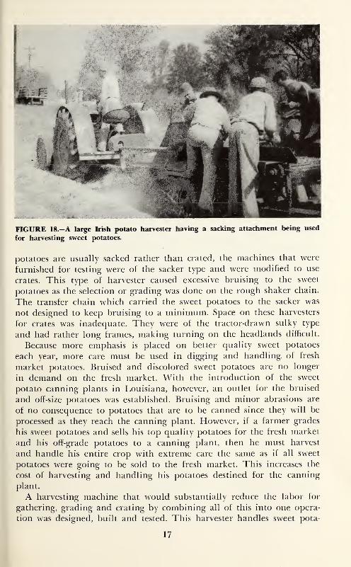
FIGURE 18.—A large Irish potato harvester having a sacking attachment being used
for harvesting sweet potatoes.
potatoes are usually sacked rather than crated, the machines that were
furnished for testing were of the sacker type and were modified to use
crates. This type of harvester caused excessive bruising to the sweet
potatoes as the selection or grading was done on the rough shaker chain.
The transfer chain which carried the sweet potatoes to the sacker was
not designed to keep bruising to a minimum. Space on these harvesters
for crates was inadequate. They were of the tractor-drawn sulky type
and had rather long frames, making turning on the headlands difficult.
Because more emphasis is placed on better quality sweet potatoes
each year, more care must be used in digging and handling of fresh
market potatoes. Bruised and discolored sweet potatoes are no longer
in demand on the fresh market. With the introduction of the sweet
potato canning plants in Louisiana, however, an outlet for the bruised
and off-size potatoes was established. Bruising and minor abrasions are
of no consequence to potatoes that are to be canned since they will be
processed as they reach the canning plant. However, if a farmer grades
his sweet potatoes and sells his top quality potatoes for the fresh market
and his off-grade potatoes to a canning plant, then he must harvest
and handle his entire crop with extreme care the same as if all sweet
potatoes were going to be sold to the fresh market. This increases the
cost of harvesting and handling his potatoes destined for the canning
plant.
A harvesting machine that would substantially reduce the labor for
gathering, grading and crating by combining all of this into one opera-
tion was designed, built and tested. This harvester handles sweet pota-
17
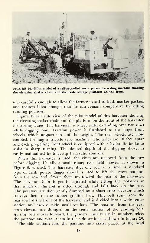
FIGURE 19.—Pilot model of a self-propelled sweet potato harvesting machine showing
the elevating shaker chain and the crate storage platform on the front.
toes carefully enough to allow the farmer to sell to fresh market packers
and reduces labor enough that he can remain competitive by selling
canning potatoes.
Figure 19 is a side view of the pilot model of this harvester showing
the elevating shaker chain and the platform on the front of the harvester
for storing crates. The harvester is 8 feet wide, extending over two rows
while digging one. Traction power is furnished to the large front
wheels, which support most of the weight. The rear wheels are close
coupled, forming a tricycle type machine. The axles are 10 feet apart
and each propelling front wheel is equipped with a hydraulic brake to
assist in sharp turning. The desired depth of the digging shovel is
easily maintained by fingertip hydraulic controls.
When this harvester is used, the vines are removed from the row
before digging. Usually a small rotary type field mower, as shown in
Figure 6, is used. The harvester digs one row at a time. A standard
type of Irish potato digger shovel is used to lift the sweet potatoes
from the row and elevate them up toward the rear of the harvester.
The elevator chain is gently agitated while lifting the potatoes so
that much of the soil is sifted through and falls back on the row.
The potatoes are then gently dumped on a short cross elevator which
conveys them to the rubber grading belt. This belt runs from the
rear toward the front of the harvester and is divided into a wide center
section and two outside small sections. The potatoes from the rear
cross elevator are dumped on the center section of the grading belt.
As this belt moves forward, the graders, usually six in number, select
the potatoes and place them in the side sections as shown in Figure 20.
The side sections feed the potatoes into crates placed at the head
18
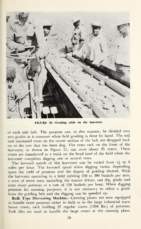
FIGURE 20.-Grading table on the harvester.
ot each side belt. The potatoes can, in this manner, be divided into
two grades as is common when field grading is done by hand. The soil
and unwanted roots on the center section of the belt are dropped back
on to the row that has been dug. The crate rack on the front of the
harvester, as shown in Figure 21, can store about 35 crates. These
crates are transferred to a truck on the head land of the field when the
harvester completes digging one or several rows.
The forward speeds of this harvester can be varied from 1/9 to 9
miles per hour. The forward speed when digging varies, depending
upon the yield of potatoes and the degree of grading desired. With
the harvester operating in a field yielding 250 to 300 bushels per acre,
a crew of seven men, including the tractor driver, can dig, grade and
crate sweet potatoes at a rate of 120 bushels per hour. When digging
potatoes for canning purposes, it is not necessary to select a grade
from the grading belt and the digging can be speeded up.
Bulk Type Harvesting Machine.-Canning plants are now equipped
to handle sweet potatoes either in bulk or in the large industrial ware-
house crates, each holding 27 regular crates (1350 lbs.) of potatoes.
Fork lifts are used to handle the large crates at the canning plant.
19
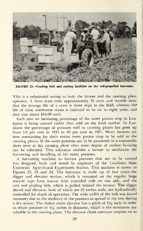
FIGURE 21.—Grading belt and crating facilities on the self-propelled harvester.
This is a substantial saving to both the farmer and the canning plant
operator. A farm crate costs approximately 45 cents and records show
that the average life of a crate is three trips to the field, whereas th^
life of these warehouse crates is estimatd to be six to eight years, and
they cost about $16.00 each.
Each year an increasing percentage of the sweet potato crop in Lou-
isiana is being canned rather than sold on the fresh market. In Lou-
isiana the percentage of potatoes sold to canning plants has gone up
from 7.6 per cent in 1941 to 46 per cent in 1961. Many farmers are
now contracting for their entire sweet potato crop to be sold to the
canning plants. If the sweet potatoes are to be processed in a reasonably
short time at the canning plant then some degree of surface bruising
can be tolerated. This tolerance enables a farmer to mechanize the
harvesting and handling of his sweet potatoes.
A harvesting machine to harvest potatoes that are to be canned
was designed, built and tested by engineers of the Louisiana State
University Agricultural Experiment Station. This machine is shown in
Figures 22, 23 and 24. The harvester is made up of two units—the
digger and elevator section, which is mounted on the regular large
tricycle type farm tractor with extended axle on one side, and the
cart and grading belt, which is pulled behind the tractor. The digger
shovel and elevator, both of which are 26 inches wide, are hydraulically
controlled for depth of operation. The wide width of the belt was found
necessary due to the tendency of the potatoes to spread in the row during
a dry season. The shaker chain elevator has a pitch of li/g inch in order
to retain potatoes of I14 inches in diameter, which is the minimum size
saleable to the canning plant. The elevator chain conveyor empties on to
20
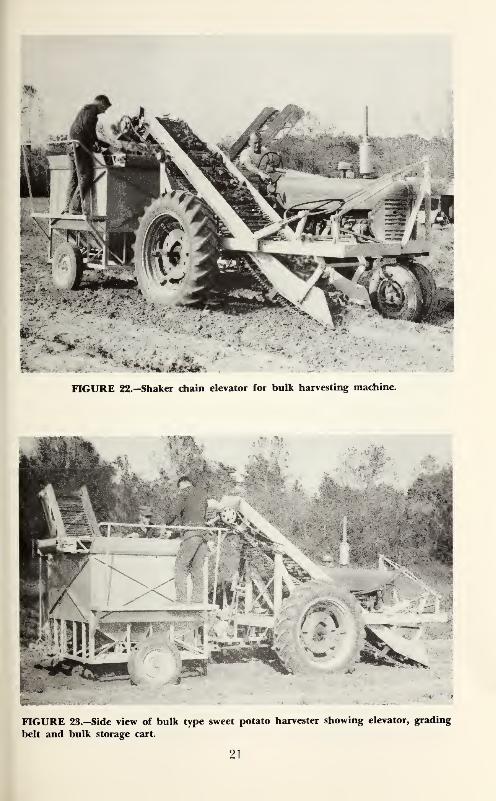
FIGURE 22.—Shaker chain elevator for bulk harvesting machine.
FIGURE 23.—Side view o£ bulk type sweet potato harvester showing elevator, grading
belt and bulk storage cart.
21
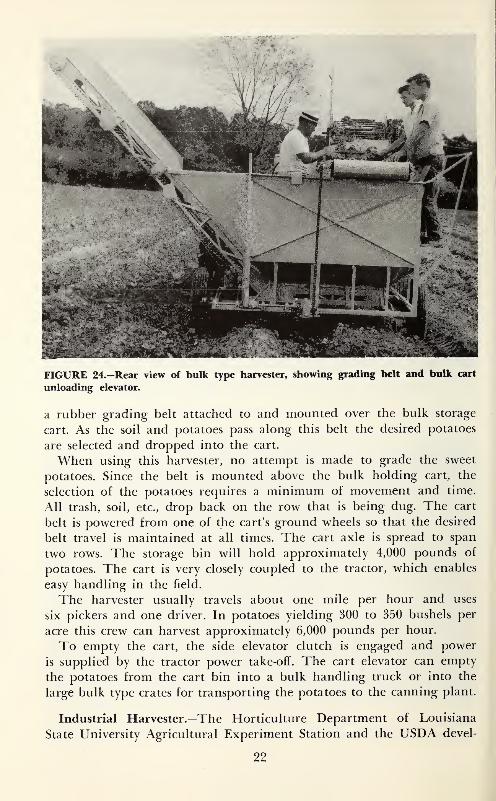
FIGURE 24.—Rear view of bulk type harvester, showing grading belt and bulk cart
unloading elevator.
a rubber grading belt attached to and mounted over the bulk storage
cart. As the soil and potatoes pass along this belt the desired potatoes
are selected and dropped into the cart.
When using this harvester, no attempt is made to grade the sweet
potatoes. Since the belt is mounted above the bulk holding cart, the
selection of the potatoes requires a minimum of movement and time.
All trash, soil, etc., drop back on the row that is being dug. The cart
belt is powered from one of the cart's ground wheels so that the desired
belt travel is maintained at all times. The cart axle is spread to span
two rows. The storage bin will hold approximately 4,000 pounds of
potatoes. The cart is very closely coupled to the tractor, which enables
easy handling in the field.
The harvester usually travels about one mile per hour and uses
six pickers and one driver. In potatoes yielding 300 to 350 bushels per
acre this crew can harvest approximately 6,000 pounds per hour.
To empty the cart, the side elevator clutch is engaged and power
is supplied by the tractor power take-off. The cart elevator can empty
the potatoes from the cart bin into a bulk handling truck or into the
large bulk type crates for transporting the potatoes to the canning plant.
Industrial Harvester.—The Horticulture Department of Louisiana
State University Agricultural Experiment Station and the USDA devel-
22
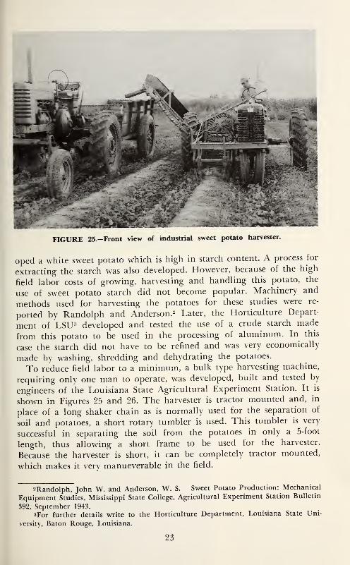
FIGURE 25.—Front view of industrial sweet potato harvester.
oped a white sweet potato which is high in starch content. A process for
extracting the starch was also developed. However, because of the high
field labor costs of growing, harvesting and handling this potato, the
use of sweet potato starch did not become popular. Machinery and
methods used for harvesting the potatoes for these studies were re-
ported by Randolph and Anderson.^ Later, the Horticulture Depart-
ment of LSU-^ developed and tested the use of a crude starch made
from this potato to be used in the processing of aluminum. In this
case the starch did not have to be refined and was very economically
made by washing, shredding and dehydrating the potatoes.
To reduce field labor to a minimum, a bulk type harvesting machine,
requiring only one man to operate, was developed, built and tested by
engineers of the Louisiana State Agricultural Experiment Station. It is
shown in Figures 25 and 26. The harvester is tractor mounted and, in
place of a long shaker chain as is normally used for the separation of
soil and potatoes, a short rotary tumbler is used. This tumbler is very
successful in separating the soil from the potatoes in only a 5-foot
length, thus allowing a short frame to be used for the harvester.
Because the harvester is short, it can be completely tractor mounted,
which makes it very manueverable in the field.
2Randolph, John W. and Anderson, W. S. Sweet Potato Production: Mechanical
Equipment Studies, Mississippi State College, Agricultural Experiment Station Bulletin
392, September 1943.
3For further details write to the Horticulture Department, Louisiana State Uni-
versity, Baton Rouge, Louisiana.
23
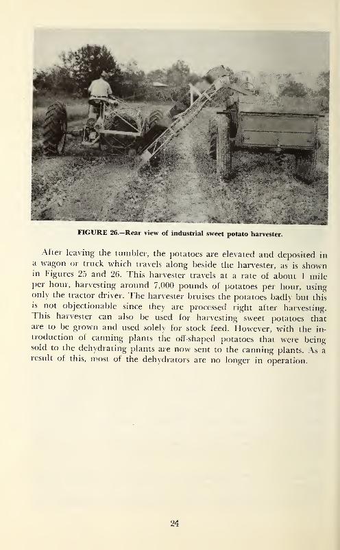
FIGURE 26.—Rear view of industrial sweet potato harvester.
After leaving the tumbler, the potatoes are elevated and deposited ina wagon or truck which travels along beside the harvester, as is shownin Figures 25 and 26. This harvester travels at a rate of about 1 mileper hour, harvesting around 7,000 pounds of potatoes per hour, usingonly the tractor driver. The harvester bruises the potatoes badly but this
is not objectionable since they are processed right after harvesting.This harvester can also be used for harvesting sweet potatoes thatare to be grown and used solely for stock feed. However, with the in-
troduction of canning plants the oft-shaped potatoes that were beingsold to the dehydrating plants are now sent to the canning plants. As aresult of this, most of the dehydrators are no longer in operation.
24
Response of Rice to
Fertilizer Phosphorus & Potassium
as delated to
levels of Available P and KIn Soils of Southwest Louisiana
j: piterson
b. sturgis
R. J, MlgARS
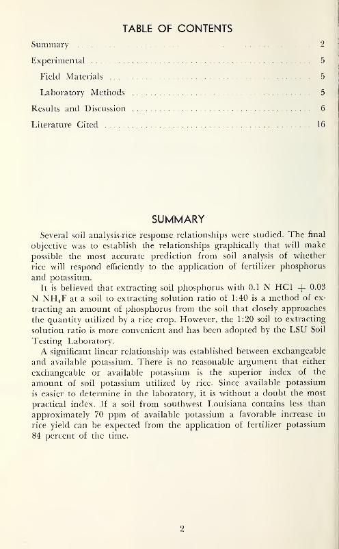
TABLE OF CONTENTS
Summary 2
Experimental 5
Field Materials 5
Laboratory Methods 5
Results and Discussion 6
Literature Cited 16
SUMMARYSeveral soil analysis-rice response relationships were studied. The final
objective was to establish the relationships graphically that will make
possible the most accurate prediction from soil analysis of whether
rice will respond efficiently to the application of fertilizer phosphorus
and potassium.
It is believed that extracting soil phosphorus with 0.1 N HCl 4" 0.03
N NH4F at a soil to extracting solution ratio of 1:40 is a method of ex-
tracting an amount of phosphorus from the soil that closely approaches
the quantity utilized by a rice crop. However, the 1:20 soil to extracting
solution ratio is more convenient and has been adopted by the LSU Soil
Testing Laboratory.
A significant linear relationship was established between exchangeable
and available potassium. There is no reasonable argument that either
exchangeable or available potassium is the superior index of the
amount of soil potassium utilized by rice. Since available potassium
is easier to determine in the laboratory, it is without a doubt the most
practical index. If a soil from southwest Louisiana contains less than
approximately 70 ppm of available potassium a favorable increase in
rice yield can be expected from the application of fertilizer potassium
84 percent of the time.
2
Response of Rice
To Fertilizer Phosphorus and PotassiumAs Related to Levels of Available PhosphorusAnd Potassium in Soils of Southwest Louisiana
F.J. Peterson, M. B. Sturgis, and R.
J.Miears^
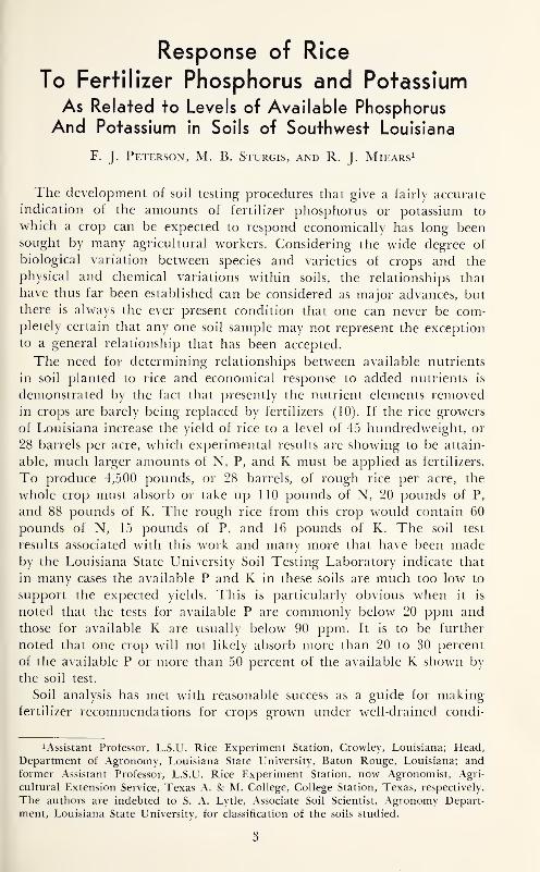
The development of soil testing procedures that give a fairly accurate
indication of the amounts of fertilizer phosphorus or potassium to
which a crop can be expected to respond economically has long beensought by many agricultural workers. Considering the wide degree of
biological variation between species and varieties of crops and the
physical and chemical variations within soils, the relationships that
have thus far been established can be considered as major advances, butthere is always the ever present condition that one can never be com-pletely certain that any one soil sample may not represent the exception
to a general relationship that has been accepted.
The need for determining relationships between available nutrients
in soil planted to rice and economical response to added nutrients is
demonstrated by the fact that presently the nutrient elements removedin crops are barely being replaced by fertilizers (10). If the rice growers
of Louisiana increase the yield of rice to a level of 45 hundredweight, or
28 barrels per acre, which experimental results are showing to be attain-
able, much larger amounts of N, P, and K must be applied as fertilizers.
To produce 4,500 pounds, or 28 barrels, of rough rice per acre, the
whole crop must absorb or take up 110 pounds of N, 20 pounds of P,
and 88 pounds of K. The rough rice from this crop would contain 60
pounds of N, 15 pounds of P, and 16 pounds of K. The soil test
results associated with this work and many more that have been madeby the Louisiana State University Soil Testing Laboratory indicate that
in many cases the available P and K in these soils are much too low to
support the expected yields. This is particularly obvious when it is
noted that the tests for available P are commonly below 20 ppm andthose for available K are usually below 90 ppm. It is to be further
noted that one crop will not likely absorb more than 20 to 30 percent
of the available P or more than 50 percent of the available K shown by
the soil test.
Soil analysis has met with reasonable success as a guide for makingfertilizer recommendations for crops grown under well-drained condi-
lAssistant Professor, L.S.U. Rice Experiment Station, Crowley, Louisiana; Head,
Department of Agionomy, Louisiana State University, Baton Rouge, Louisiana; andformer Assistant Professor, L.S.U. Rice Experiment Station, now Agronomist, Agri-
cultural Extension Service, Texas A. Sc M. College, College Station, Texas, respectively.
The authors are indebted to S. A. Lytle, Associate Soil Scientist, Agronomy Depart-
ment, Louisiana State University, for classification of the soils studied.
3
3g'5
OJo
Xo
1^
,^
»0
>o
>oxo
I--
JO1^
OX
(M
CM
CM
CM
^XI
ou
^S-i
:ch
:ch
rch
rch
Sepi
Mai
Mai
Mai
Mai
^u
S=
--
>>
Cc
OJo
o
au
ogG
CC
ij-^S
^^^S'S
>^''t3i^
<U<W^^^<><W<W>
cg
>>
03
03
cc
oo
C/3
C/3
S-l
(L)
OJ
its
itt
<^
111
uwo
.S
gOJ
!-i
dj
03
J2
owley
nton
owley
elsh
els
els
2^
03
OJ
OJ
03
03
03
W3
rz:
03>
S3
OS
c/5
C/3
«5
^
.[in
W^W
XgH
uc
<J
c
u3^
•S.S
OS
03
wuoU
(U
^_
I—
IOJo
c5
^ i:
o.5
<u
WUOuOuOOpqUU
oo
ss
03
^i-
OJ
9J
UUU
pq
CQ
gqj
<u
^3
1I
---OP
irj
lo
irj
in
lo
lOo
ir-,o
lo
it;
xo
xo
xo
lO
xn
CMeo'^in(Oi>-ooa>0^iMcoTt^mot-c»cn
2<u
03
|>
4
tions. However, according to Reed and Sturgis (9), flooding soils that
are planted to rice causes certain variation in the physical, chemical
and biological characteristics ot the soils which limits the use of results
from presently established soil-analysis techniques for predicting yield
responses of rice to added fertilizer phosphorus and potassium.
A four-year study of the relationships involved between soil phos-
phorus and potassium and responses to fertilizer phosphorus and po-
tassium has been conducted with rice on some of the representative
soils in the rice growing area of southwest Louisiana. The objectives
of this study were (a) to establish the relationship between exchange-
able or available potassium in the soil and the response of rice to added
potash, and (b) to investigate the relationship between available phos-
phorus extracted at four different soil to extracting solution ratios and
the response of rice to fertilizer phosphate.
EXPERIMENTAL
Field Materials
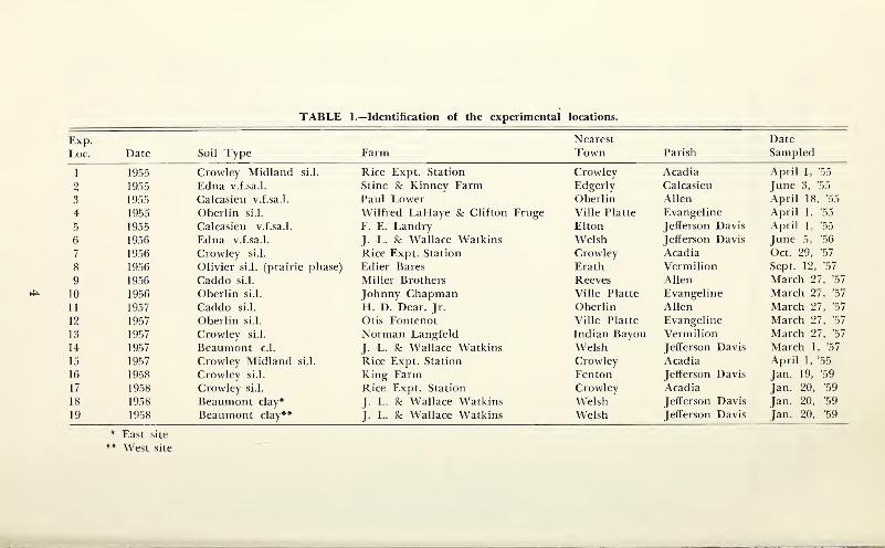
These investigations have been made in cooperation with the rice
fertility experiments conducted in 1955, 1956, 1957, and 1958 at the
Rice Experiment Station and at locations scattered through the rice area
of southwest Louisiana (Table 1). Descriptions of the experimental
designs and rice yields at each location have been reported by Miears
in the Annual Progress Reports of the Rice Experiment Station (4, 5,
6, 7). Selected field data from the experimental locations are presented
in Tables 3 and 4.
A composite sample of soil from the A horizon was taken at each
experimental location. Samples were taken before the treatments were
applied or from the non-treated plots.
Laboratory Methods
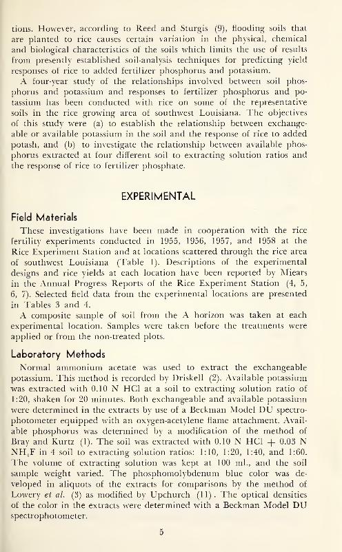
Normal ammonium acetate w^as used to extract the exchangeable
potassium. This method is recorded by Driskell (2). Available potassium
was extracted with 0.10 N HCl at a soil to extracting solution ratio of
1:20, shaken for 20 minutes. Both exchangeable and available potassium
were determined in the extracts by use of a Beckman Model DU spectro-
photometer equipped with an oxygen-acetylene flame attachment. Avail-
able phosphorus was determined by a modification of the method of
Bray and Kurtz (1). The soil was extracted with 0.10 N HCl + 0.08 NNH^F in 4 soil to extracting solution ratios: 1:10, 1:20, 1:40, and 1:60.
The volume of extracting solution w^as kept at 100 ml., and the soil
sample weight varied. The phosphomolybdenum blue color was de-
veloped in aliquots of the extracts for comparisons by the method of
Lowery et al. (3) as modified by Upchurch (11). The optical densities
of the color in the extracts w^ere determined with a Beckman Model DUspectrophotometer.
5
RESULTS AND DISCUSSION
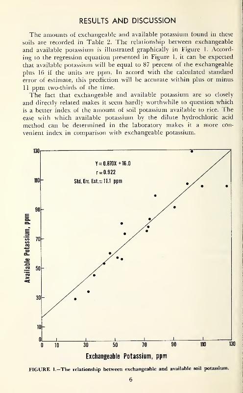
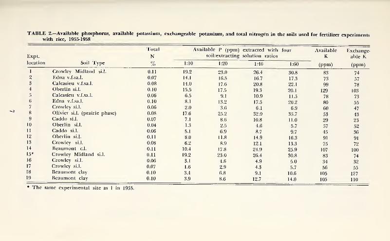
The amounts ot exchangeable and available potassium found in these
soils are recorded in Table 2. The relationship between exchangeable
and available potassium is illustrated graphically in Figure 1. Accord-
ing to the regression equation presented in Figure 1, it can be expected
that available potassium will be equal to 87 percent of the exchangeable
plus 16 if the units are ppm. In accord with the calculated standard
error of estimate, this prediction will be accurate within plus or minus
11 ppm two-thirds of the time.
The fact that exchangeable and available potassium are so closely
and directly related makes it seem hardly worthwhile to question which
is a better index of the amount of soil potassium available to rice. Theease with which available potassium by the dilute hydrochloric acid
method can be determined in the laboratory makes it a more con-
venient index in comparison with exchangeable potassium.
130
110
90
30
•
V _ n Qinv 4- ic nY = U.o/Ua +lb,U
r = 0.922
-Std. Err. Est.rr 11.1 ppm y . •
•
-
•// ••
/ •
-
y •-
)-
) 1 1 11 1 1
10 30 50 70
Exchangeable Potassium, ppm
FIGURE l.-The relationship between exchangeable and available soil potassium.
130
QJ
-S3
tj
.2
is
3X
o
£s
co
a,
c5
CM
ITS
J>.o
OO
lO
(M
J>-CO
CO
irjlo
OCO
0^^
oO
CO
t-^
^csr
Oifjoo
COd
,r;
,^
_:
^•
^
--;pq--Hq-;pqqpq--:q--;—qq-H^
oodddddddddddddddcSd
a,
wuOu
uo
>§
ou
-ac
•s
:H-
«-S-~
g„
OUOUCQUUUWCQ
7
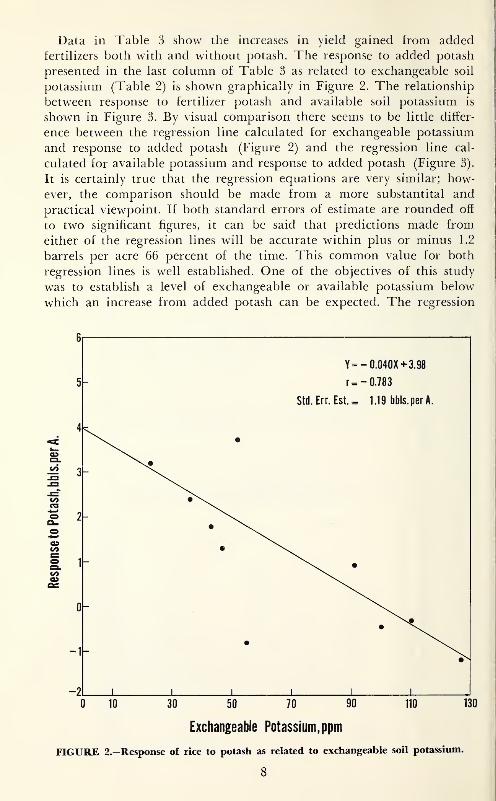
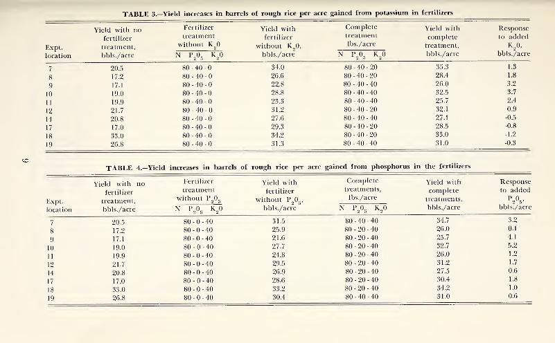
Data in Table 3 show the increases in yield gained from added
fertilizers both with and without potash. The response to added potash
presented in the last column of Table 3 as related to exchangeable soil
potassium (Table 2) is shown graphically in Figure 2. The relationship
between response to fertilizer potash and available soil potassium is
shown in Figure 3. By visual comparison there seems to be little differ-
ence between the regression line calculated for exchangeable potassium
and response to added potash (Figure 2) and the regression line cal-
culated for available potassium and response to added potash (Figure 3).
It is certainly true that the regression equations are very similar; how-
ever, the comparison should be made from a more substantital and
practical viewpoint. If both standard errors of estimate are rounded off
to two significant figures, it can be said that predictions made from
either of the regression lines will be accurate within plus or minus 1.2
barrels per acre 66 percent of the time. This common value for both
regression lines is well established. One of the objectives of this study
was to establish a level of exchangeable or available potassium below
which an increase from added potash can be expected. The regression
^ 3
-1
-2
Y=- 0.040X+3.98
r=- 0.783
Std.Err.Est.= 1.19 bbls.perA.
•
•
•
1i 1 1 1 1
0 10 11030 50 70 90
Exchangeable Potassium, ppm
FIGURE 2.—Response of rice to potash as related to exchangeable soil potassium.
8
130
IsI1iIIt
^^
OJ
ill
illi
^^
inqq
gooooooooo
^ooooooooo
oooooooooo
ooooooooooooocoooooo
11
oqoqoocvfqcoc^co
oooooooooo
oooooooooo
^^qqt^oqqqoq
5:^22
g5^
S
OOOSO-^CsTTf^r-OOCTi
III
ill
ill
III
HI
t^qt^r>;qcNfiOT^;c^{q
Tt^dioc^xo-^t-^OTh^
oooooooooo
OoOOOoOOoO
OOooOOOOOOoOGOOOooOO
00oqq
(>{
crio
00
COo
c\r
cvf5^
oo
it
ii
11
OOoo^o^Ooo
oooooooooo
incsf— ^qqr^oqqqoq
ot^r-^cnc5-^Oj>Icoo
00oo
(>J
Tt<
00
CT5
lines provide a good means oi determining this level but predictionsfrom their use will be accurate only within plus or minus 1.2 barrelsper acre. Therefore, the only safe predictions of yield increases willbe made for values of response that are equal to or greater than 1.2
barrels per acre. For example, by following the 1.2 barrel per acre valuein Figure 2 horizontally across until it intersects with the regression line,
it can be expected that a soil having 69 ppm exchangeable potassiumwill give a yield response to added potash 84 percent of the time. If
this same procedure is used with Figure 3, it can be shown that a soil
having 71 ppm available potassium could be expected to give a yieldresponse to added potash 84 percent of the time. By this method ofinterpretation, a soil having 69 ppm of exchangeable potassium or 71ppm available potassium can be expected to give a yield responseto added potash that may vary between 0 and 2.4 barrels per acre.
Since the values, 69 and 71 ppm, of exchangeable or available potas-sium are so close together as to be within laboratory experimentalerror, either exchangeable or available potassium would serve as a satis-
factory index for estimating the amount of soil potassium available to
6| —
Y=-0.048X+4.61
Available Potassium, ppm
FIGURE 3.—Response of rice to potash as related to available soil potassium.
10
40
Soil to Extracting Solution Ratios Used
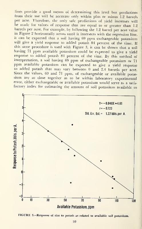
FIGURE 4.—Effect of soil to extracting solution ratios on the amount of phosphorusextracted at each experimental location.
11
rice. It can be concluded that similar soils having less than approximately
70 ppm exchangeable or available potassium will give a favorable yield
response to added potash 84 percent of the time.
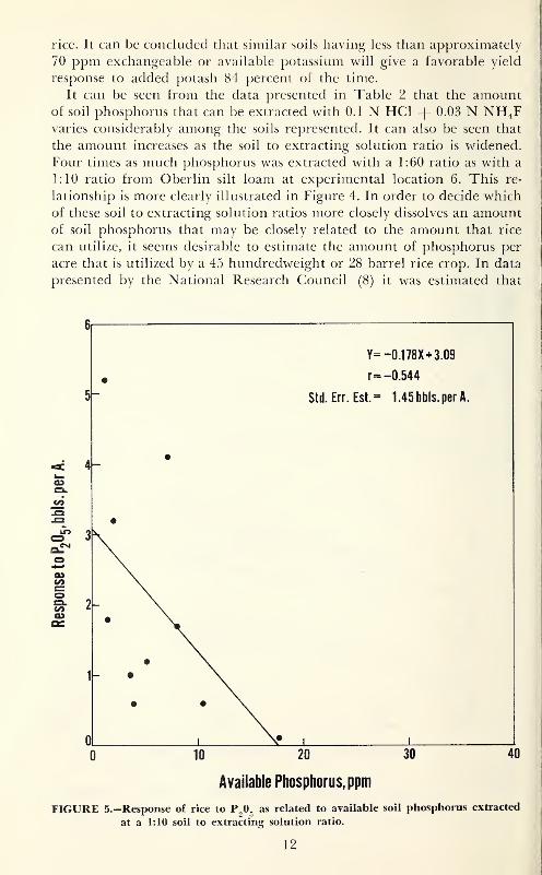
It can be seen from the data presented in Table 2 that the amountof soil phosphorus that can be extracted with 0.1 N HCl + 0.03 N NH4Fvaries considerably among the soils represented. It can also be seen that
the amount increases as the soil to extracting solution ratio is widened.
Four times as much phosphorus was extracted with a 1:60 ratio as with a
1:10 ratio from Oberlin silt loam at experimental location 6. This re-
lationship is more clearly illustrated in Figure 4. In order to decide which
of these soil to extracting solution ratios more closely dissolves an amountof soil phosphorus that may be closely related to the amount that rice
can utilize, it seems desirable to estimate the amount of phosphorus per
acre that is utilized by a 45 hundredweight or 28 barrel rice crop. In data
presented by the National Research Council (8) it was estimated that
6
5-
Y= -0.178X+3.09
r= -0.544
St(l.Err.Est.= 1.45bbls.per A.
OL
0 10 20 30 40
12
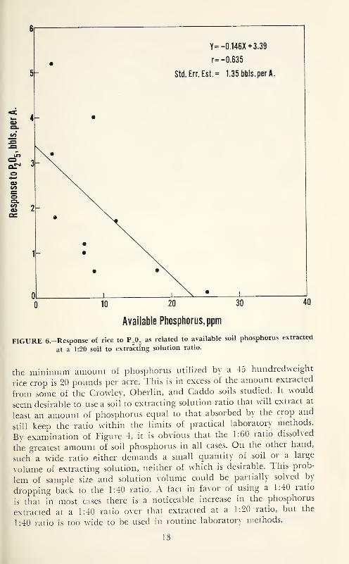
Y=-0.146X + 3.39
r= -0.635
Std.Err.Est.= 1.35 bbls.per A.
Available Phosphorus, ppm
FIGURE 6.-Response of rice to P.O. as related to available soil phosphorus extracted
at a 1:20 soil to extracting solution ratio.
the minimum amount of phosphorus utilized bv a 45 hundredweight
rice crop is 20 pounds per acre. This is in excess of the amount extracted
from some of the Cro^vle\, Oberlin, and Caddo soils studied. It would
seem desirable to use a soil to extracting solution ratio that will extract at
least an amount of phosphorus ec^ual to that absorbed bv the crop and
still keep the ratio ^vithin the limits of practical laboratory methods.
By examination of Figure 4, it is obvious that the 1:60 ratio dissolved
the greatest amount of soil phosphorus in all cases. On the other hand,
such a wide ratio either demands a small quantity of soil or a large
volume of extracting solution, neither of which is desirable. This prob-
lem of sample size and solution volume could be partiallv solved by
dropping back to the 1:40 ratio. A fact in favor of using a 1:40 ratio
IS that in most cases there is a noticeable increase in the phosphorus
extracted at a 1:40 ratio over that extracted at a 1:20 ratio, but the
1:40 ratio is too ^\4de to be used in routine laboratory methods.
5-
13
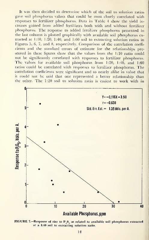
It was then decided to determine whicii ot the soil to solution ratios
gave soil phosphorus values that could be most closely correlated withresponses to fertilizer phosphorus. Data in Table 4 show the yield in-
creases gained from added fertilizers both with and without fertilizer
phosphorus. The response to added fertilizer phosphorus presented in
the last column is plotted graphically with available soil phosphorus ex-
tracted at 1:10, 1:20, 1:40, and 1:60 soil to extracting solution ratios in
Figures 5, 6, 7, and 8, respectively. Comparison of the correlation coeffi-
cients and the standard errors of estimate for the relationships pre-
sented in these figures show that the values from the 1:10 ratio couldnot be significantly correlated with responses to fertilizer phosphorus.
The values for available soil phosphorus from 1:20, 1:40, and 1:60
ratios could be correlated with responses to fertilizer phosphorus. Thecorrelation coefficients were significant and so nearly alike in value that
it could not be said that one represented a better relationship thanthe other. The 1:20 soil to solution ratio is easiest to work with in
Y=-0.116X + 3.50
r= -0.638
Std.Err.Est.= 1.35bbls.perA.
Available Phosphorus, ppm
FIGURE 7.—Response of rice to P^O^ as related to available soil phosphorus extracted
at a 1:40 soil to extracting solution ratio.
14
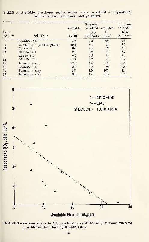
TABLE 5.—Available phosphorus and potassium in soil as related to responses of
rice to fertilizer phosphorus and potassium
Expt.
location Soil Type
Available
P(ppm)
Response
to added
bbls./acre
Available
K(ppm)
Response
to addedK,0,
bbls./acre
7 Crowley si.l. 3.6 3.2 60 1.3
8 Olivier si.l. (prairie phase) 25.2 0.1 53 1.8
9 Caddo si.l. 8.6 4.1 29 3.2
10 Oberlin si.l 2.5 5.2 57 3.7
11 Caddo si.l. 6.9 1.2 45 2.4
12 Oberlin si.l. 11.8 1.7 91 0.9
14 Beaumont c.l. 17.8 0.6 107 -0.5
17 Crowley si.l. 2.9 1.8 56 -0.8
18 Beaumont clay 6.8 1.0 105 -1.2
19 Beaumont clay 8.6 0.6 105 -0.3
Y=-0.111X+3.58
r= -0.649
St{I.Err.Est.= 1.33 bbls.perA.
10 40
Available Phosphorus, ppm
FIGURE 8.—Response of rice to P^O^ as related to available soil phosphorus extracted
at a 1:60 soil to extracting solution ratio.
15
practical routine. II the intersection ol the horizontal response line
eqtial to the standard error of estimate and the regression line (Figure
6) is established in the same manner as was done for potassium, rice
grown on a soil from which 14 ppm or less of available phosphorus are
extracted by the 1:20 ratio can be expected to give a response to added
fertilizer phosphorus of from zero to 2.7 barrels per acre 84
percent of the time. By using this type of interpretation in Figure 7
when the 1:40 ratio is used, response to fertilizer phosphorus occurs at or
below 19 ppm available soil phosphorus. Likewise, in Figure 8, when the
1:60 ratio is employed response begins at or below 21 ppm.
The data in Table 5 show that, in general, available phosphorus in
the soils represented in the experiments was low, particularly in soils of
the Oberlin, Crowley, and Caddo series. At 8 of the 10 experimental
locations, the soil contained less than 14 ppm of available phosphorus.
Among these locations, the response to fertilizer phosphorus varied
from 0.6 to 5.2 barrels of rice per acre.
The data in Table 5 show that the soils were relatively low in avail-
able potassium.. The soil at 6 of the 10 experimental locations contained
less than 70 ppm available potassium. In 5 of the 6 locations, the response
to fertilizer potassium varied from 1.3 to 3.7 barrels of rice per acre.
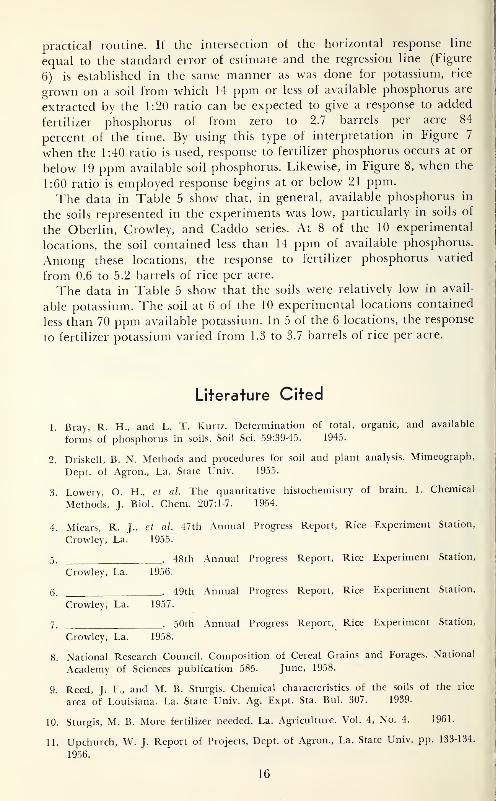
Literature Cited
1. Bray, R. H., and L. T. Kurtz. Determination of total, organic, and available
forms of phosphorus in soils. Soil Sci. 59:39-45. 1945.
2. Driskell, B. N. Methods and procedures for soil and plant analysis. Mimeograph,
Dept. of Agron., La. State Univ. 1955.
3. Lowery, O. H., et al. The quantitative histochemistry of brain. I. Chemical
Methods. J.Biol. Chem. 207:1-7. 1954.
4. Miears, R. J.,et al. 47th Annual Progress Report, Rice Experiment Station,
Crowley, La. 1955.
5. . 48th Annual Progress Report, Rice Experiment Station,
Crowley, La. 1956.
6. . 49th Annual Progress Report, Rice Experiment Station,
Crowley, La. 1957.
7. . 50th Annual Progress Report, Rice Experiment Station,
Crowley, La. 1958.
8. National Research Council. Composition of Cereal Grains and Forages. National
Academy of Sciences publication 585. June, 1958.
9. Reed, J. F., and M. B. Sturgis. Chemical characteristics of the soils of the rice
area of Louisiana. La. State Univ. Ag. Expt. Sta. Bui. 307. 1939.
10. Sturgis, M. B. More fertilizer needed. La. Agriculture. Vol. 4, No. 4. 1961.
11. Upchurch, W. J. Report of Projects, Dept. of Agron., La. State Univ. pp. 133-134.
1956.
16