Embed Size (px)
Citation preview
1
HARVEST TEC, INC
MODEL 493
100 & 110 GALLON AUTOMATIC HAY PRESERVATIVE APPLICATOR
FOR LARGE SQUARE BALERS
HARVEST TEC, INC PO BOX 63
HUDSON, WI 54016 EMAIL: [email protected]
2
Installation Kit Reference Step 1: Mounting the tank on the baler
*New Holland & Case IH LBX series balers 4
*Vermeer SQ2731 & SQ3347 balers 5
*Claas 2200 balers 6
*Hesston 4750,4755, 4760 4790, 4900,4910, and Case IH 8570, 8575,8585, 8580, 8590,and Challenger –LB33, LB34, LB44, and New Idea 7233,7234,7244, and 7333
7
Step 2: Mounting the pump holder on the tank saddle 8
Step 3: Location of the drain and fill line 8
Step 4: Mounting the star wheels on the baler 9
*Case IH 8570,8575,8585, and Challenger LB33,LB34, and Hesston 4750,4755, 4790, -and New Idea 7233, 7234, and 7333
9
*Case IH 8580, 8590, and Hesston 4900, 4910, and Challenger LB44, and New Idea 7244 10
*Claas 2200 10
*New Holland 590, 595, BB940, BB960, and Case IH LBX 331, and LBX431 11
*Vermeer SQ2731 and SQ3347 11
Step 5: Wire the star wheel to the signal conditioner- 12
Step 6: Connecting flow meter to signal conditioner 12
Step 7: Bale rate sensor installation 12
Step 8: Main wiring harness installation 12
Wire installation 13
Step 9: Installation of the spray shield 14
*4438A-Vermeer SQ2731 14
*4439A-Vermeer SQ3347 14
*4490A-Case IH 8570 and 8575, Hesston 4750 and 4755, and New Idea 7233 15
*4491A-Hesston 4900, 4910, Challenger LB44, Case IH 8580,8590,and New Idea 7244 15
*4492A-Hesston 4790, Case IH 8585, Challenger LB34, and New Idea 7234 16
*4494A-Challenger LB33, Hesston 4760, and New Idea 7333 16
*4495A-New Holland 590 and 595, BB940, BB960, and Case IH LBX331 and LBX341 17
*4497A-Case IH LBX 331 and LBX441, and New Holland BB940 and BB960 roto cut 17
*4499A-Claas 18
*4500A- Installation kit 4500A for Hesston 4760 , New Idea 7333, and Challenger LB 33 with Cutter Option 19
Step 10: Plumbing 19
Step 11: Install the mounting bracket inside the tractor cab 19
Step 12: Install controller cable harness 19
Step 13: Install the main power leads 19
Step 14: Operating instructions 21
Step 15: First time and annual start up instructions 22
Priming and checking the pumps 22
Turning the control on/off and the main menu 23
To change application rates 23
To change the moisture set points 23
T change bale rate settings 24
To run in the automatic bale rate mode 24
To run in the manual bale rate mode 24
Automatic mode or manual mode descriptions 24
To run in automatic mode 25
To run the applicator in manual mode 25
To pause the unit 25
To override the system and apply full application 26
To read and reset the amount of preservative used 26
Adjusting the volume of the control box alarm 26
Common questions about the 464 26
Routine maintenance 27
Winter storage 27
Trouble shooting checks on the 464 control system 28
System error code guide 31
Wiring plug diagram 32
Parts breakdown for pump plate 34
Table of Contents 010-0493 REV 11/03
3
Parts breakdown for star wheel and hoses 35
Parts breakdown for control box and wiring harnesses 36
Parts breakdown for parts b ags 37
Installation kit parts breakdowns 38
*4438A and 4439A 38
*4490A and 4491A 39
*4492A and 4494A 40
*4495A and 4497A 41
*4498A and 4499A 42
*4500A 43
Tank, saddle, and legs part #’s 44
Template 45
Warranty statement 46
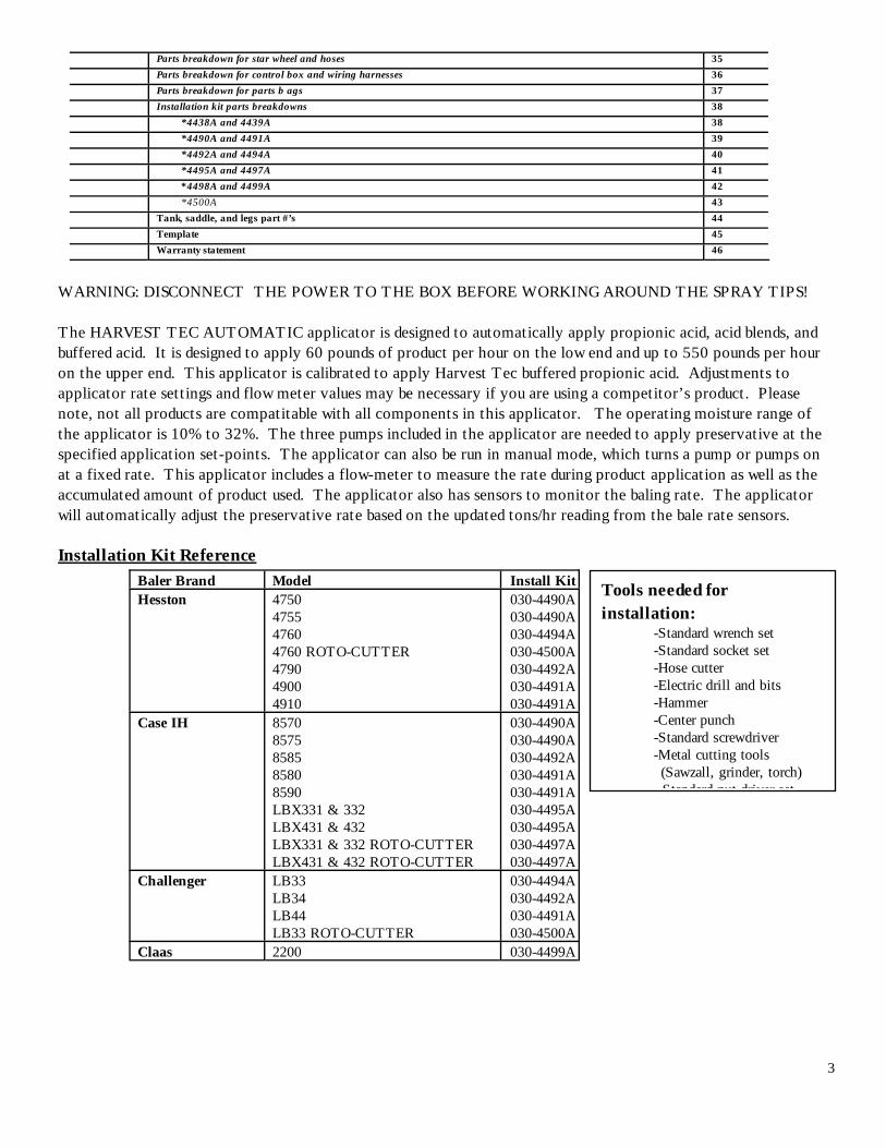
WARNING: DISCONNECT THE POWER TO THE BOX BEFORE WORKING AROUND THE SPRAY TIPS! The HARVEST TEC AUTOMATIC applicator is designed to automatically apply propionic acid, acid blends, and buffered acid. It is designed to apply 60 pounds of product per hour on the low end and up to 550 pounds per hour on the upper end. This applicator is calibrated to apply Harvest Tec buffered propionic acid. Adjustments to applicator rate settings and flow meter values may be necessary if you are using a competitor’s product. Please note, not all products are compatitable with all components in this applicator. The operating moisture range of the applicator is 10% to 32%. The three pumps included in the applicator are needed to apply preservative at the specified application set-points. The applicator can also be run in manual mode, which turns a pump or pumps on at a fixed rate. This applicator includes a flow-meter to measure the rate during product application as well as the accumulated amount of product used. The applicator also has sensors to monitor the baling rate. The applicator will automatically adjust the preservative rate based on the updated tons/hr reading from the bale rate sensors.
Installation Kit Reference Baler Brand Model Install Kit Hesston
4750 4755 4760 4760 ROTO-CUTTER 4790 4900 4910
030-4490A 030-4490A 030-4494A 030-4500A 030-4492A 030-4491A 030-4491A
Case IH 8570 8575 8585 8580 8590 LBX331 & 332 LBX431 & 432 LBX331 & 332 ROTO-CUTTER LBX431 & 432 ROTO-CUTTER
030-4490A 030-4490A 030-4492A 030-4491A 030-4491A 030-4495A 030-4495A 030-4497A 030-4497A
Challenger LB33 LB34 LB44 LB33 ROTO-CUTTER
030-4494A 030-4492A 030-4491A 030-4500A
Claas 2200 030-4499A
Tools needed for installation:
-Standard wrench set -Standard socket set -Hose cutter
-Electric drill and bits -Hammer -Center punch
-Standard screwdriver -Metal cutting tools (Sawzall, grinder, torch) Standard nut driver set
4
New Idea 7233 7234 7244 7333 7333 ROTO-CUTTER
030-4490A 030-4492A 030-4491A
030-4494A030-4500A
New Holland 590 595 BB940 & BB940A BB960 & BB960A BB940 & BB940A ROTO-CUTTER BB960 & BB960A ROTO-CUTTER
030-4495A 030-4495A 030-4495A 030-4495A 030-4497A 030-4497A
Vermeer SQ2731 SQ3347
030-4438A 030-4439A
All others Universal 030-4495A
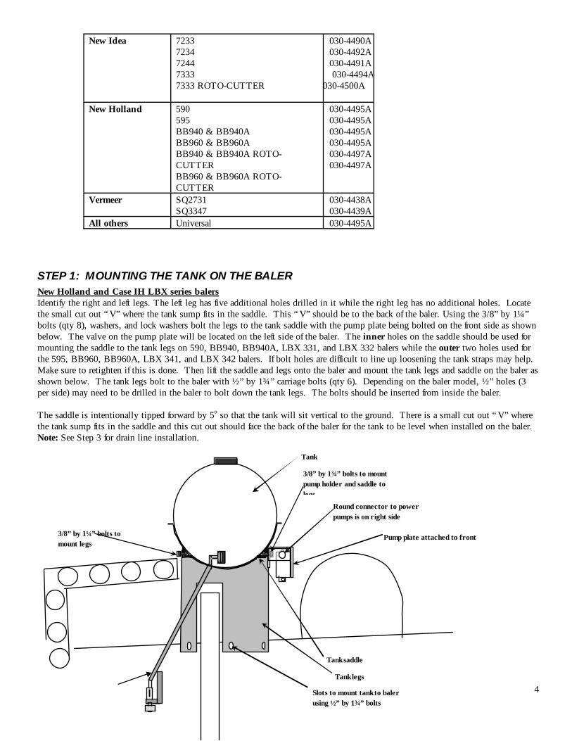
STEP 1: MOUNTING THE TANK ON THE BALER New Holland and Case IH LBX series balers Identify the right and left legs. The left leg has five additional holes drilled in it while the right leg has no additional holes. Locate the small cut out “ V” where the tank sump fits in the saddle. This “ V” should be to the back of the baler. Using the 3/8” by 1¼” bolts (qty 8), washers, and lock washers bolt the legs to the tank saddle with the pump plate being bolted on the front side as shown below. The valve on the pump plate will be located on the left side of the baler. The inner holes on the saddle should be used for mounting the saddle to the tank legs on 590, BB940, BB940A, LBX 331, and LBX 332 balers while the outer two holes used for the 595, BB960, BB960A, LBX 341, and LBX 342 balers. If bolt holes are difficult to line up loosening the tank straps may help. Make sure to retighten if this is done. Then lift the saddle and legs onto the baler and mount the tank legs and saddle on the baler as shown below. The tank legs bolt to the baler with ½” by 1¾” carriage bolts (qty 6). Depending on the baler model, ½” holes (3 per side) may need to be drilled in the baler to bolt down the tank legs. The bolts should be inserted from inside the baler. The saddle is intentionally tipped forward by 5o so that the tank will sit vertical to the ground. There is a small cut out “ V” where the tank sump fits in the saddle and this cut out should face the back of the baler for the tank to be level when installed on the baler. Note: See Step 3 for drain line installation.
Pump plate attached to front
Tank
3/8” by 1¾” bolts to mount pump holder and saddle to legs
Tank legs
Tank saddle
Slots to mount tank to baler using ½” by 1¾” bolts
3/8” by 1¼” bolts to mount legs
Round connector to power pumps is on right side
5
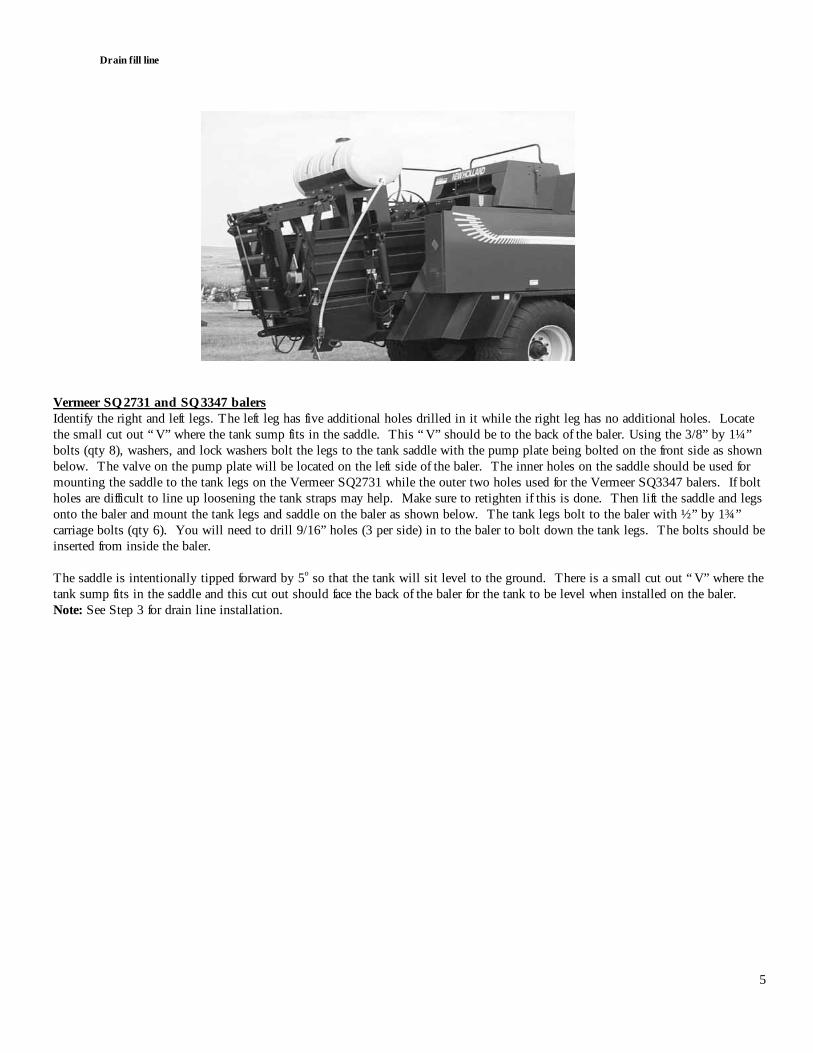
Vermeer SQ2731 and SQ3347 balers Identify the right and left legs. The left leg has five additional holes drilled in it while the right leg has no additional holes. Locate the small cut out “ V” where the tank sump fits in the saddle. This “ V” should be to the back of the baler. Using the 3/8” by 1¼” bolts (qty 8), washers, and lock washers bolt the legs to the tank saddle with the pump plate being bolted on the front side as shown below. The valve on the pump plate will be located on the left side of the baler. The inner holes on the saddle should be used for mounting the saddle to the tank legs on the Vermeer SQ2731 while the outer two holes used for the Vermeer SQ3347 balers. If bolt holes are difficult to line up loosening the tank straps may help. Make sure to retighten if this is done. Then lift the saddle and legs onto the baler and mount the tank legs and saddle on the baler as shown below. The tank legs bolt to the baler with ½” by 1¾” carriage bolts (qty 6). You will need to drill 9/16” holes (3 per side) in to the baler to bolt down the tank legs. The bolts should be inserted from inside the baler. The saddle is intentionally tipped forward by 5o so that the tank will sit level to the ground. There is a small cut out “ V” where the tank sump fits in the saddle and this cut out should face the back of the baler for the tank to be level when installed on the baler. Note: See Step 3 for drain line installation.
Drain fill line
6
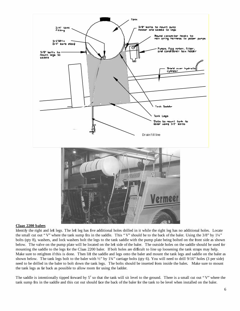
Claas 2200 balers Identify the right and left legs. The left leg has five additional holes drilled in it while the right leg has no additional holes. Locate the small cut out “ V” where the tank sump fits in the saddle. This “ V” should be to the back of the baler. Using the 3/8” by 1¼” bolts (qty 8), washers, and lock washers bolt the legs to the tank saddle with the pump plate being bolted on the front side as shown below. The valve on the pump plate will be located on the left side of the baler. The outside holes on the saddle should be used for mounting the saddle to the legs for the Claas 2200 baler. If bolt holes are difficult to line up loosening the tank straps may help. Make sure to retighten if this is done. Then lift the saddle and legs onto the baler and mount the tank legs and saddle on the baler as shown below. The tank legs bolt to the baler with ½” by 1¾” carriage bolts (qty 6). You will need to drill 9/16” holes (3 per side) need to be drilled in the baler to bolt down the tank legs. The bolts should be inserted from inside the baler. Make sure to mount the tank legs as far back as possible to allow room for using the ladder. The saddle is intentionally tipped forward by 5o so that the tank will sit level to the ground. There is a small cut out “ V” where the tank sump fits in the saddle and this cut out should face the back of the baler for the tank to be level when installed on the baler.
Drain fill line
7
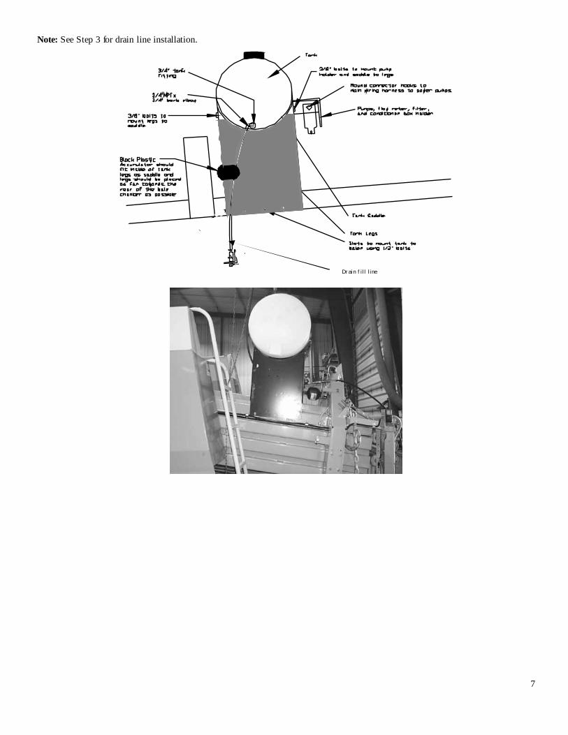
Note: See Step 3 for drain line installation.
Drain fill line
8
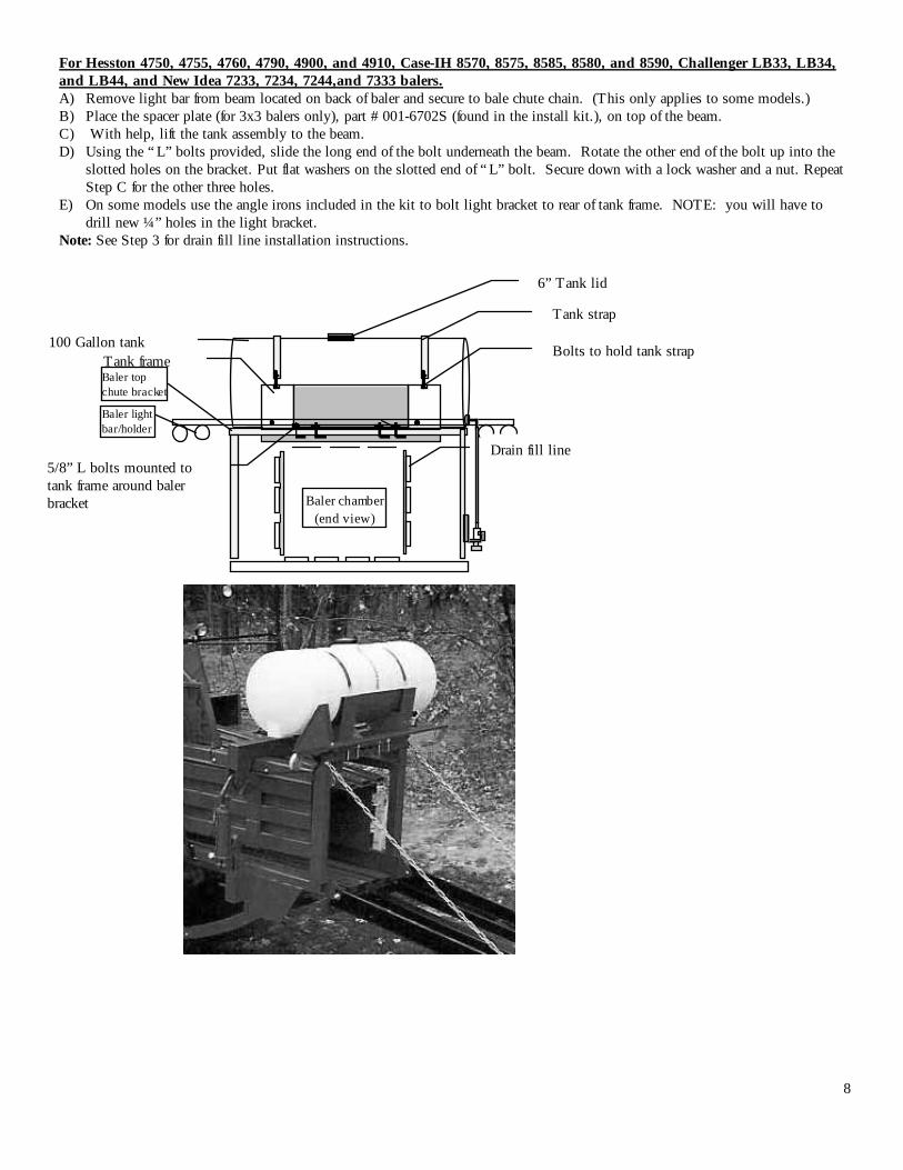
For Hesston 4750, 4755, 4760, 4790, 4900, and 4910, Case-IH 8570, 8575, 8585, 8580, and 8590, Challenger LB33, LB34, and LB44, and New Idea 7233, 7234, 7244,and 7333 balers. A) Remove light bar from beam located on back of baler and secure to bale chute chain. (This only applies to some models.) B) Place the spacer plate (for 3x3 balers only), part # 001-6702S (found in the install kit.), on top of the beam. C) With help, lift the tank assembly to the beam. D) Using the “ L” bolts provided, slide the long end of the bolt underneath the beam. Rotate the other end of the bolt up into the
slotted holes on the bracket. Put flat washers on the slotted end of “ L” bolt. Secure down with a lock washer and a nut. Repeat Step C for the other three holes.
E) On some models use the angle irons included in the kit to bolt light bracket to rear of tank frame. NOTE: you will have to drill new ¼” holes in the light bracket.
Note: See Step 3 for drain fill line installation instructions.
Baler light bar/holder
Baler top chute bracket
Baler chamber (end view)
6” Tank lid
Tank strap
Bolts to hold tank strap
Drain fill line
100 Gallon tank Tank frame
5/8” L bolts mounted to tank frame around baler bracket
9
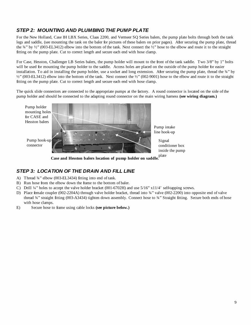
STEP 2: MOUNTING AND PLUMBING THE PUMP PLATE For the New Holland, Case IH LBX Series, Claas 2200, and Vermeer SQ Series balers, the pump plate bolts through both the tank legs and saddle, (see mounting the tank on the baler for pictures of these balers on prior pages). After securing the pump plate, thread the ¾” by ½” (003-EL3412) elbow into the bottom of the tank. Next connect the ½” hose to the elbow and route it to the straight fitting on the pump plate. Cut to correct length and secure each end with hose clamp. For Case, Hesston, Challenger LB Series balers, the pump holder will mount to the front of the tank saddle. Two 3/8” by 1” bolts will be used for mounting the pump holder to the saddle. Access holes are placed on the outside of the pump holder for easier installation. To aid in installing the pump holder, use a socket and long extension. After securing the pump plate, thread the ¾” by ½” (003-EL3412) elbow into the bottom of the tank. Next connect the ½” (002-9001) hose to the elbow and route it to the straight fitting on the pump plate. Cut to correct length and secure each end with hose clamp. The quick slide connectors are connected to the appropriate pumps at the factory. A round connector is located on the side of the pump holder and should be connected to the adapting round connector on the main wiring harness (see wiring diagram.)
Case and Hesston balers location of pump holder on saddle.
STEP 3: LOCATION OF THE DRAIN AND FILL LINE A) Thread ¾” elbow (003-EL3434) fitting into end of tank. B) Run hose from the elbow down the frame to the bottom of baler. C) Drill ¼” holes to accept the valve holder bracket (001-6702H) and use 5/16” x11/4’ self-tapping screws. D) Place female coupler (002-2204A) through valve holder bracket, thread into ¾” valve (002-2200) into opposite end of valve
thread ¾” straight fitting (003-A3434) tighten down assembly. Connect hose to ¾” Straight fitting. Secure both ends of hose with hose clamps.
E) Secure hose to frame using cable locks (see picture below.)
Pump hook-up connector
Pump intake line hook-up
Pump holder mounting holes for CASE and Hesston balers
Signal conditioner box inside the pump plate
10
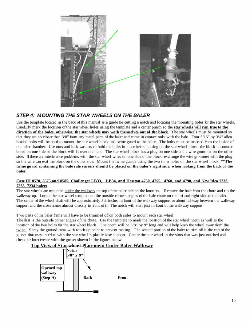
STEP 4: MOUNTING THE STAR WHEELS ON THE BALER Use the template located in the back of this manual as a guide for cutting a notch and locating the mounting holes for the star wheels. Carefully mark the location of the star wheel holes using the template and a center punch so the star wheels will run true to the direction of the bales, otherwise, the star wheels may work themselves out of the block. The star wheels must be mounted so that they are no closer than 3/8” from any metal parts of the baler and come in contact only with the bale. Four 5/16” by 3¼” allen headed bolts will be used to mount the star wheel block and twine guard to the baler. The bolts must be inserted from the inside of the baler chamber. Use nuts and lock washers to hold the bolts in place before putting on the star wheel block, the block is counter-bored on one side so the block will fit over the nuts. The star wheel block has a plug on one side and a wire grommet on the other side. If there are interference problems with the star wheel wires on one side of the block, exchange the wire grommet with the plug so the wire can exit the block on the other side. Mount the twine guards using the two inner holes on the star wheel block. **The twine guard containing the bale rate sensors should be placed on the baler’s right side, when looking from the back of the baler. Case IH 8570, 8575,and 8585, Challenger LB33, LB34, and Hesston 4750, 4755, 4760, and 4790, and New Idea 7233, 7333, 7234 balers The star wheels are mounted under the walkway on top of the baler behind the knotters. Remove the bale from the chute and tip the walkway up. Locate the star wheel template on the outside corners angles of the bale chute on the left and right side of the baler. The center of the wheel shaft will be approximately 5½ inches in front of the walkway support or about halfway between the walkway support and the cross frame almost directly in front of it. The notch will start just in front of the walkway support. Two parts of the baler frame will have to be trimmed off on both sides to mount each star wheel. The first is the outside corner angles of the chute. Use the template to mark the location of the star wheel notch as well as the location of the four holes for the star wheel block. The notch will be 5/8” by 9” long and will help keep the wheel away from the twine. Spray the ground areas with touch up paint to prevent rusting. The second portion of the baler to trim off is the end of the gusset that may interfere with the star wheel’s plastic base support. Center the star wheel in the slots that was just notched and check for interference with the gusset shown in the figures below. Top View of Star wheel Placement Under Baler Walkway
Opened top walkway (Step A)
Notch 5/8” x 9”
Back Front
11
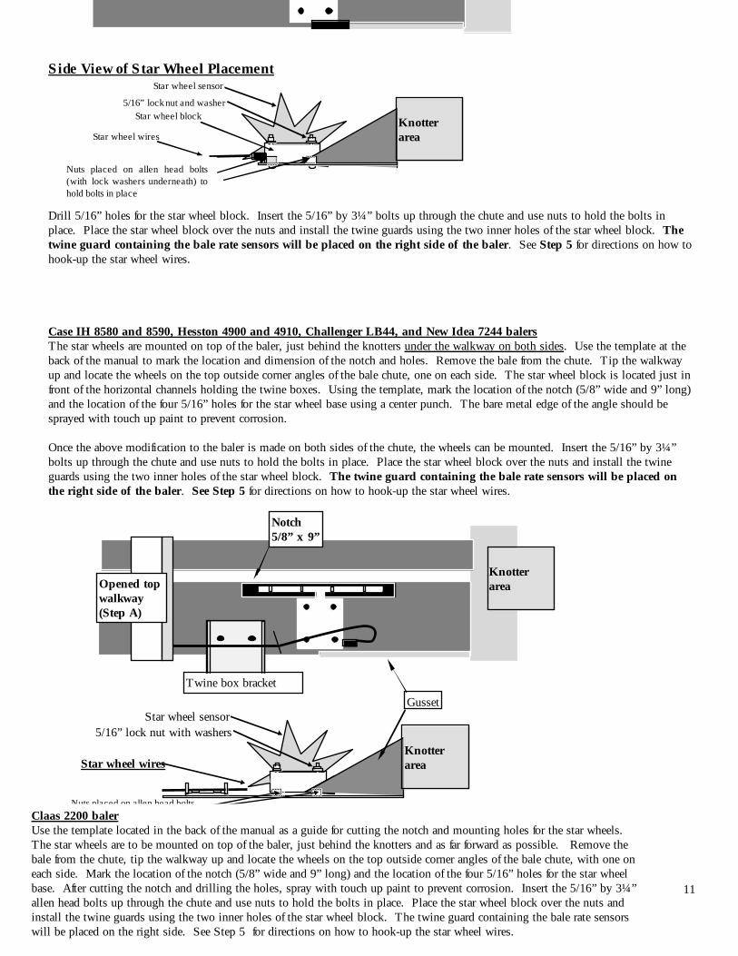
Side View of Star Wheel Placement
Drill 5/16” holes for the star wheel block. Insert the 5/16” by 3¼” bolts up through the chute and use nuts to hold the bolts in place. Place the star wheel block over the nuts and install the twine guards using the two inner holes of the star wheel block. The twine guard containing the bale rate sensors will be placed on the right side of the baler. See Step 5 for directions on how to hook-up the star wheel wires. Case IH 8580 and 8590, Hesston 4900 and 4910, Challenger LB44, and New Idea 7244 balers The star wheels are mounted on top of the baler, just behind the knotters under the walkway on both sides. Use the template at the back of the manual to mark the location and dimension of the notch and holes. Remove the bale from the chute. Tip the walkway up and locate the wheels on the top outside corner angles of the bale chute, one on each side. The star wheel block is located just in front of the horizontal channels holding the twine boxes. Using the template, mark the location of the notch (5/8” wide and 9” long) and the location of the four 5/16” holes for the star wheel base using a center punch. The bare metal edge of the angle should be sprayed with touch up paint to prevent corrosion.
Once the above modification to the baler is made on both sides of the chute, the wheels can be mounted. Insert the 5/16” by 3¼” bolts up through the chute and use nuts to hold the bolts in place. Place the star wheel block over the nuts and install the twine guards using the two inner holes of the star wheel block. The twine guard containing the bale rate sensors will be placed on the right side of the baler. See Step 5 for directions on how to hook-up the star wheel wires.
Notch 5/8” x 9”
Gusset
Opened top walkway (Step A)
Knotter area
Star wheel sensor 5/16” lock nut with washers
Knotter area
Star wheel sensor
5/16” lock nut and washer Star wheel block
Star wheel wires
Knotter area
Twine box bracket
Star wheel wires
Nuts placed on allen head bolts (with lock washers underneath) to hold bolts in place
Nuts placed on allen head bolts (with lock washers underneath) to hold bolts in place
Claas 2200 baler Use the template located in the back of the manual as a guide for cutting the notch and mounting holes for the star wheels. The star wheels are to be mounted on top of the baler, just behind the knotters and as far forward as possible. Remove the bale from the chute, tip the walkway up and locate the wheels on the top outside corner angles of the bale chute, with one on each side. Mark the location of the notch (5/8” wide and 9” long) and the location of the four 5/16” holes for the star wheel base. After cutting the notch and drilling the holes, spray with touch up paint to prevent corrosion. Insert the 5/16” by 3¼” allen head bolts up through the chute and use nuts to hold the bolts in place. Place the star wheel block over the nuts and install the twine guards using the two inner holes of the star wheel block. The twine guard containing the bale rate sensors will be placed on the right side. See Step 5 for directions on how to hook-up the star wheel wires.
12
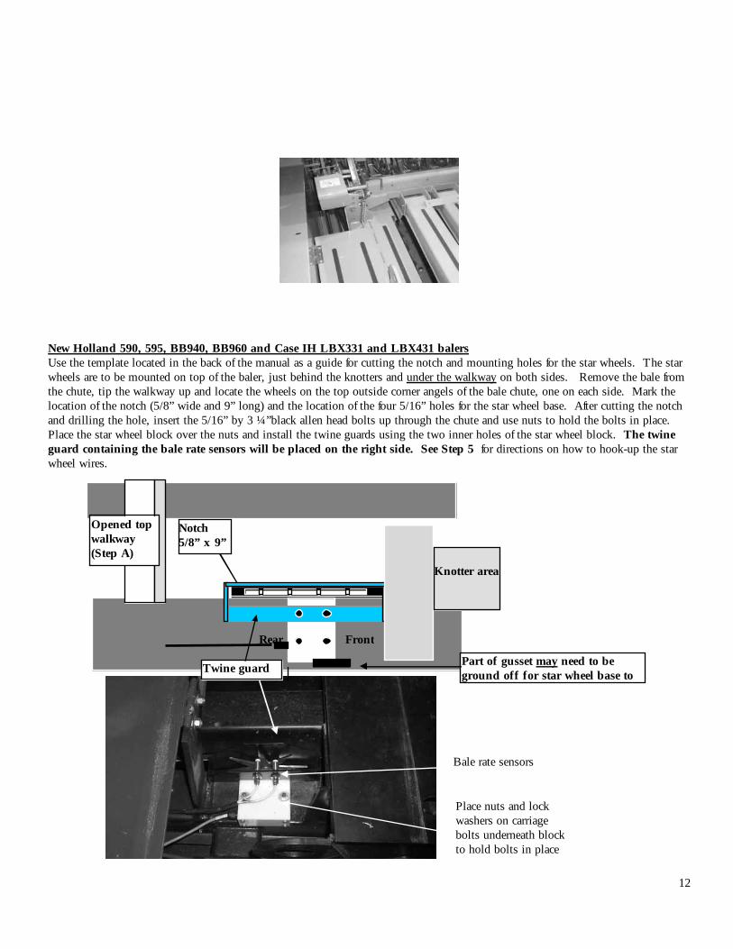
New Holland 590, 595, BB940, BB960 and Case IH LBX331 and LBX431 balers Use the template located in the back of the manual as a guide for cutting the notch and mounting holes for the star wheels. The star wheels are to be mounted on top of the baler, just behind the knotters and under the walkway on both sides. Remove the bale from the chute, tip the walkway up and locate the wheels on the top outside corner angels of the bale chute, one on each side. Mark the location of the notch (5/8” wide and 9” long) and the location of the four 5/16” holes for the star wheel base. After cutting the notch and drilling the hole, insert the 5/16” by 3 ¼”black allen head bolts up through the chute and use nuts to hold the bolts in place. Place the star wheel block over the nuts and install the twine guards using the two inner holes of the star wheel block. The twine guard containing the bale rate sensors will be placed on the right side. See Step 5 for directions on how to hook-up the star wheel wires.
Top View of Star Wheel Placement Under Baler Walkway
Notch 5/8” x 9”
Part of gusset may need to be ground off for star wheel base to
Opened top walkway (Step A)
Knotter area
Twine guard
Bale rate sensors
Place nuts and lock washers on carriage bolts underneath block to hold bolts in place
Rear Front
13
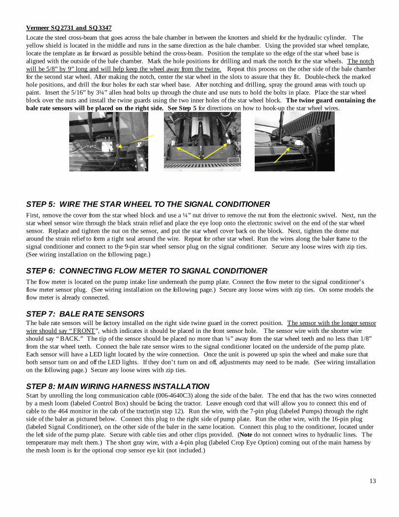
Vermeer SQ2731 and SQ3347 Locate the steel cross-beam that goes across the bale chamber in between the knotters and shield for the hydraulic cylinder. The yellow shield is located in the middle and runs in the same direction as the bale chamber. Using the provided star wheel template, locate the template as far forward as possible behind the cross-beam. Position the template so the edge of the star wheel base is aligned with the outside of the bale chamber. Mark the hole positions for drilling and mark the notch for the star wheels. The notch will be 5/8” by 9” long and will help keep the wheel away from the twine. Repeat this process on the other side of the bale chamber for the second star wheel. After making the notch, center the star wheel in the slots to assure that they fit. Double-check the marked hole positions, and drill the four holes for each star wheel base. After notching and drilling, spray the ground areas with touch up paint. Insert the 5/16” by 3¼” allen head bolts up through the chute and use nuts to hold the bolts in place. Place the star wheel block over the nuts and install the twine guards using the two inner holes of the star wheel block. The twine guard containing the bale rate sensors will be placed on the right side. See Step 5 for directions on how to hook-up the star wheel wires.
STEP 5: WIRE THE STAR WHEEL TO THE SIGNAL CONDITIONER First, remove the cover from the star wheel block and use a ¼” nut driver to remove the nut from the electronic swivel. Next, run the star wheel sensor wire through the black strain relief and place the eye loop onto the electronic swivel on the end of the star wheel sensor. Replace and tighten the nut on the sensor, and put the star wheel cover back on the block. Next, tighten the dome nut around the strain relief to form a tight seal around the wire. Repeat for other star wheel. Run the wires along the baler frame to the signal conditioner and connect to the 9-pin star wheel sensor plug on the signal conditioner. Secure any loose wires with zip ties. (See wiring installation on the following page.)
STEP 6: CONNECTING FLOW METER TO SIGNAL CONDITIONER The flow meter is located on the pump intake line underneath the pump plate. Connect the flow meter to the signal conditioner’s flow meter sensor plug. (See wiring installation on the following page.) Secure any loose wires with zip ties. On some models the flow meter is already connected.
STEP 7: BALE RATE SENSORS The bale rate sensors will be factory installed on the right side twine guard in the correct position. The sensor with the longer sensor wire should say “ FRONT”, which indicates it should be placed in the front sensor hole. The sensor wire with the shorter wire should say “ BACK.” The tip of the sensor should be placed no more than ¼” away from the star wheel teeth and no less than 1/8” from the star wheel teeth. Connect the bale rate sensor wires to the signal conditioner located on the underside of the pump plate. Each sensor will have a LED light located by the wire connection. Once the unit is powered up spin the wheel and make sure that both sensor turn on and off the LED lights. If they don’t turn on and off, adjustments may need to be made. (See wiring installation on the following page.) Secure any loose wires with zip ties.
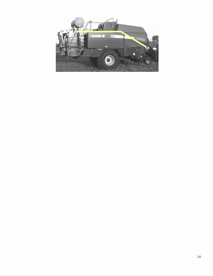
STEP 8: MAIN WIRING HARNESS INSTALLATION Start by unrolling the long communication cable (006-4640C3) along the side of the baler. The end that has the two wires connected by a mesh loom (labeled Control Box) should be facing the tractor. Leave enough cord that will allow you to connect this end of cable to the 464 monitor in the cab of the tractor(in step 12). Run the wire, with the 7-pin plug (labeled Pumps) through the right side of the baler as pictured below. Connect this plug to the right side of pump plate. Run the other wire, with the 16-pin plug (labeled Signal Conditioner), on the other side of the baler in the same location. Connect this plug to the conditioner, located under the left side of the pump plate. Secure with cable ties and other clips provided. (Note do not connect wires to hydraulic lines. The temperature may melt them.) The short gray wire, with a 4-pin plug (labeled Crop Eye Option) coming out of the main harness by the mesh loom is for the optional crop sensor eye kit (not included.)
14
15
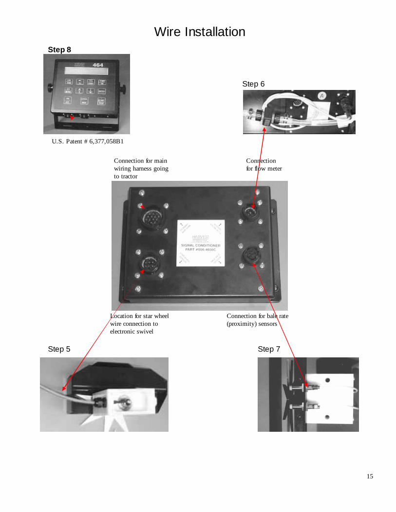
Wire Installation
Connection for bale rate (proximity) sensors
Connection for flow meter
Connection for main wiring harness going to tractor
Location for star wheel wire connection to electronic swivel
Step 8
Step 6
Step 7 Step 5
U.S. Patent # 6,377,058B1
16
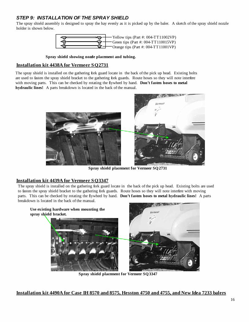
STEP 9: INSTALLATION OF THE SPRAY SHIELD The spray shield assembly is designed to spray the hay evenly as it is picked up by the baler. A sketch of the spray shield nozzle holder is shown below.
Spray shield showing nozzle placement and tubing.
Installation kit 4438A for Vermeer SQ2731
Spray shield placement for Vermeer SQ2731 Installation kit 4439A for Vermeer SQ3347
Spray shield placement for Vermeer SQ3347 Installation kit 4490A for Case IH 8570 and 8575, Hesston 4750 and 4755, and New Idea 7233 balers
Yellow tips (Part #: 004-TT11002VP) Green tips (Part #: 004-TT110015VP) Orange tips (Part #: 004-TT11001VP)
The spray shield is installed on the gathering fork guard locate in the back of the pick up head. Existing bolts are used to fasten the spray shield bracket to the gathering fork guards. Route hoses so they will note interfere with moving parts. This can be checked by rotating the flywheel by hand. Don’t fasten hoses to metal hydraulic lines! A parts breakdown is located in the back of the manual.
The spray shield is installed on the gathering fork guard locate in the back of the pick up head. Existing bolts are used to fasten the spray shield bracket to the gathering fork guards. Route hoses so they will note interfere with moving parts. This can be checked by rotating the flywheel by hand. Don’t fasten hoses to metal hydraulic lines! A parts breakdown is located in the back of the manual.
Use existing hardware when mounting the spray shield bracket.
17
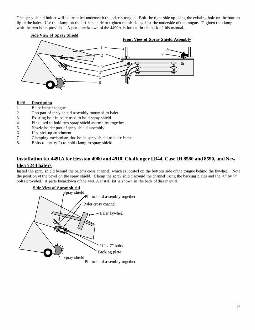
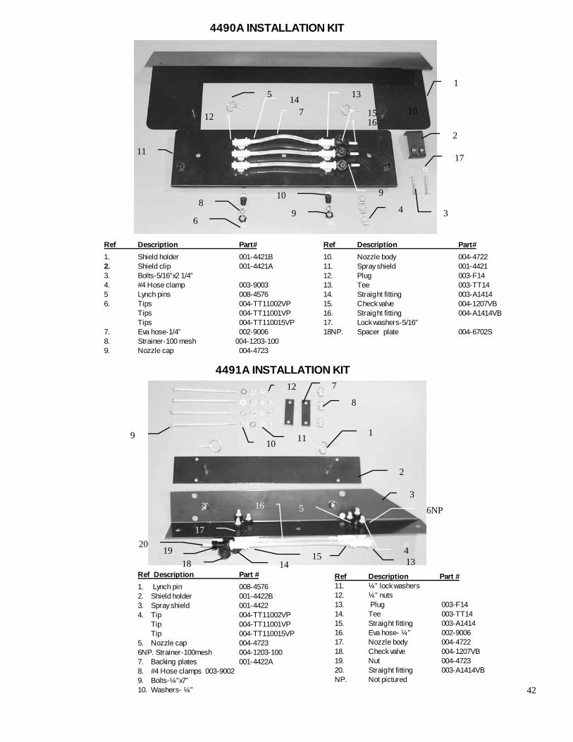
The spray shield holder will be installed underneath the baler’s tongue. Bolt the right side up using the existing hole on the bottom lip of the baler. Use the clamp on the left hand side to tighten the shield against the underside of the tongue. Tighten the clamp with the two bolts provided. A parts breakdown of the 4490A is located in the back of this manual.
Ref# Description 1. Baler frame / tongue 2. Top part of spray shield assembly mounted to baler 3. Existing bolt in baler used to hold spray shield 4. Pins used to hold two spray shield assemblies together 5. Nozzle holder part of spray shield assembly 6. Hay pick-up attachment 7. Clamping mechanism that holds spray shield to baler frame 8. Bolts (quantity 2) to hold clamp to spray shield Installation kit 4491A for Hesston 4900 and 4910, Challenger LB44, Case IH 8580 and 8590, and New Idea 7244 balers Install the spray shield behind the baler’s cross channel, which is located on the bottom side of the tongue behind the flywheel. Note the position of the bevel on the spray shield. Clamp the spray shield around the channel using the backing plates and the ¼” by 7” bolts provided. A parts breakdown of the 4491A install kit is shown in the back of this manual.
Front View of Spray Shield Assembly Side View of Spray Shield
1
2
3 4 5 6
7 8
Side View of Spray shield Spray shield
Baler cross channel
Baler flywheel
¼” x 7” bolts Backing plate
Pin to hold assembly together
Spray shield Pin to hold assembly together
18
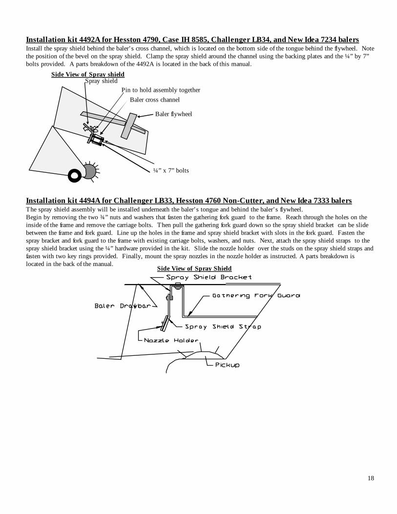
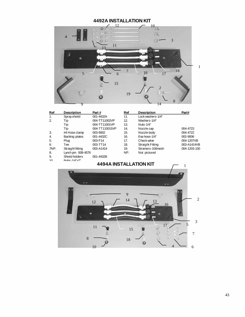
Installation kit 4492A for Hesston 4790, Case IH 8585, Challenger LB34, and New Idea 7234 balers Install the spray shield behind the baler’s cross channel, which is located on the bottom side of the tongue behind the flywheel. Note the position of the bevel on the spray shield. Clamp the spray shield around the channel using the backing plates and the ¼” by 7” bolts provided. A parts breakdown of the 4492A is located in the back of this manual. Installation kit 4494A for Challenger LB33, Hesston 4760 Non-Cutter, and New Idea 7333 balers The spray shield assembly will be installed underneath the baler’s tongue and behind the baler’s flywheel. Begin by removing the two ¾” nuts and washers that fasten the gathering fork guard to the frame. Reach through the holes on the inside of the frame and remove the carriage bolts. Then pull the gathering fork guard down so the spray shield bracket can be slide between the frame and fork guard. Line up the holes in the frame and spray shield bracket with slots in the fork guard. Fasten the spray bracket and fork guard to the frame with existing carriage bolts, washers, and nuts. Next, attach the spray shield straps to the spray shield bracket using the ¼” hardware provided in the kit. Slide the nozzle holder over the studs on the spray shield straps and fasten with two key rings provided. Finally, mount the spray nozzles in the nozzle holder as instructed. A parts breakdown is located in the back of the manual.
Side View of Spray shield Spray shield
Baler cross channel
Baler flywheel
¼” x 7” bolts
Pin to hold assembly together
Side View of Spray Shield
19
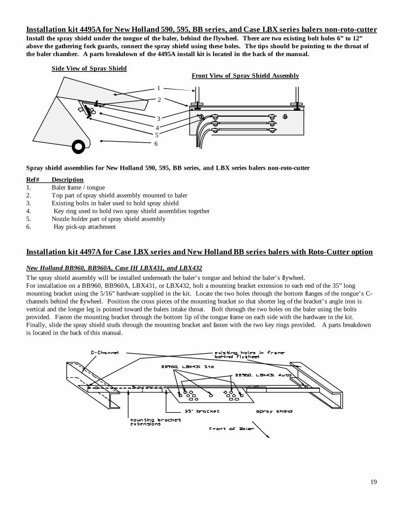
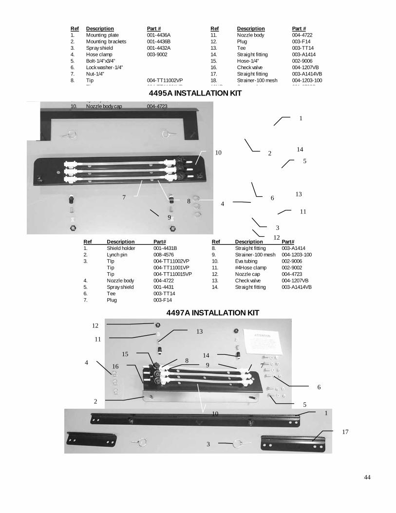
Installation kit 4495A for New Holland 590, 595, BB series, and Case LBX series balers non-roto-cutter Install the spray shield under the tongue of the baler, behind the flywheel. There are two existing bolt holes 6” to 12” above the gathering fork guards, connect the spray shield using these holes. The tips should be pointing to the throat of the baler chamber. A parts breakdown of the 4495A install kit is located in the back of the manual.
Spray shield assemblies for New Holland 590, 595, BB series, and LBX series balers non-roto-cutter
Ref# Description 1. Baler frame / tongue 2. Top part of spray shield assembly mounted to baler 3. Existing bolts in baler used to hold spray shield 4. Key ring used to hold two spray shield assemblies together 5. Nozzle holder part of spray shield assembly 6. Hay pick-up attachment Installation kit 4497A for Case LBX series and New Holland BB series balers with Roto-Cutter option
New Holland BB960, BB960A, Case IH LBX431, and LBX432 The spray shield assembly will be installed underneath the baler’s tongue and behind the baler’s flywheel. For installation on a BB960, BB960A, LBX431, or LBX432, bolt a mounting bracket extension to each end of the 35” long mounting bracket using the 5/16” hardware supplied in the kit. Locate the two holes through the bottom flanges of the tongue’s C-channels behind the flywheel. Position the cross pieces of the mounting bracket so that shorter leg of the bracket’s angle iron is vertical and the longer leg is pointed toward the balers intake throat. Bolt through the two holes on the baler using the bolts provided. Fasten the mounting bracket through the bottom lip of the tongue frame on each side with the hardware in the kit. Finally, slide the spray shield studs through the mounting bracket and fasten with the two key rings provided. A parts breakdown is located in the back of this manual.
Front View of Spray Shield Assembly Side View of Spray Shield
1
2
3 4 5 6
2
20
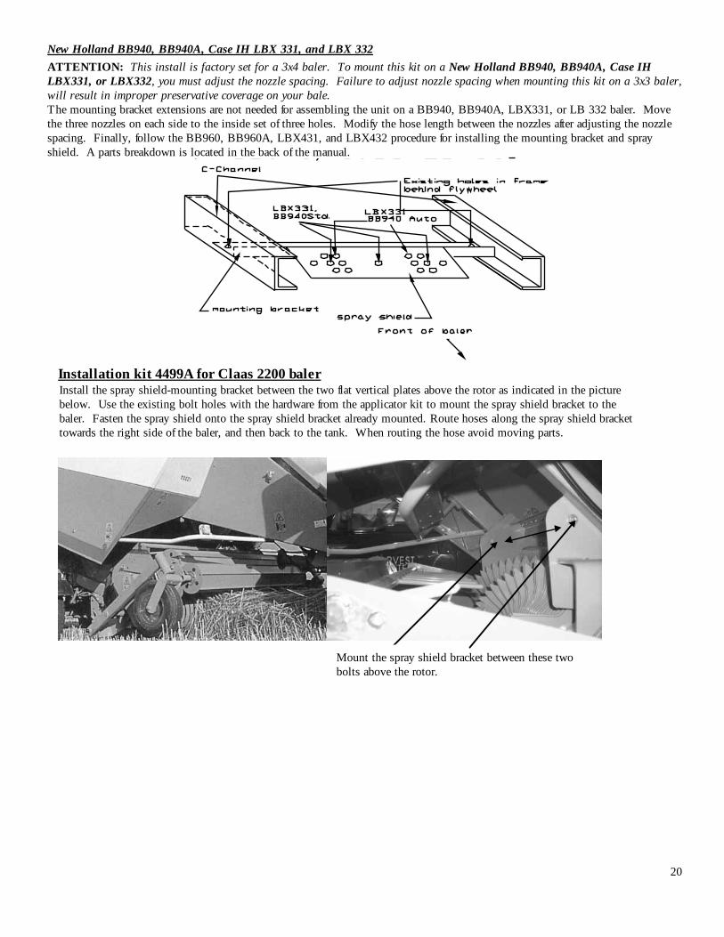
New Holland BB940, BB940A, Case IH LBX 331, and LBX 332 ATTENTION: This install is factory set for a 3x4 baler. To mount this kit on a New Holland BB940, BB940A, Case IH LBX331, or LBX332, you must adjust the nozzle spacing. Failure to adjust nozzle spacing when mounting this kit on a 3x3 baler, will result in improper preservative coverage on your bale. The mounting bracket extensions are not needed for assembling the unit on a BB940, BB940A, LBX331, or LB 332 baler. Move the three nozzles on each side to the inside set of three holes. Modify the hose length between the nozzles after adjusting the nozzle spacing. Finally, follow the BB960, BB960A, LBX431, and LBX432 procedure for installing the mounting bracket and spray shield. A parts breakdown is located in the back of the manual.
Installation kit 4499A for Claas 2200 baler
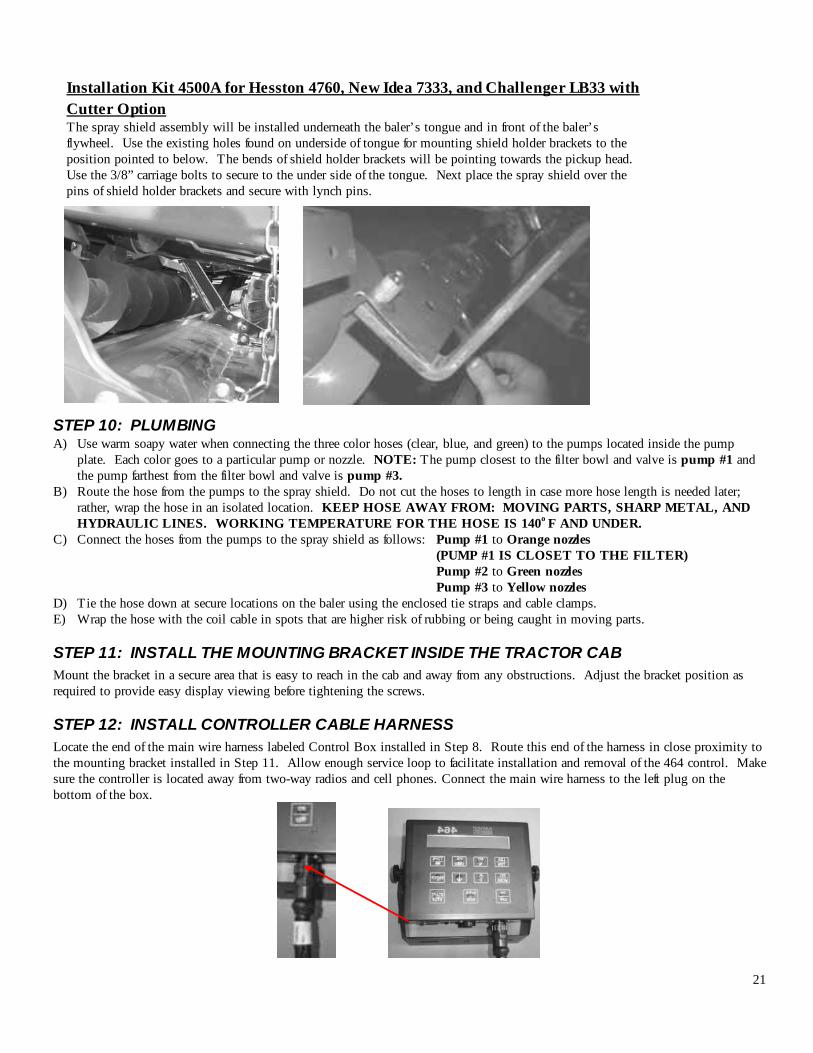
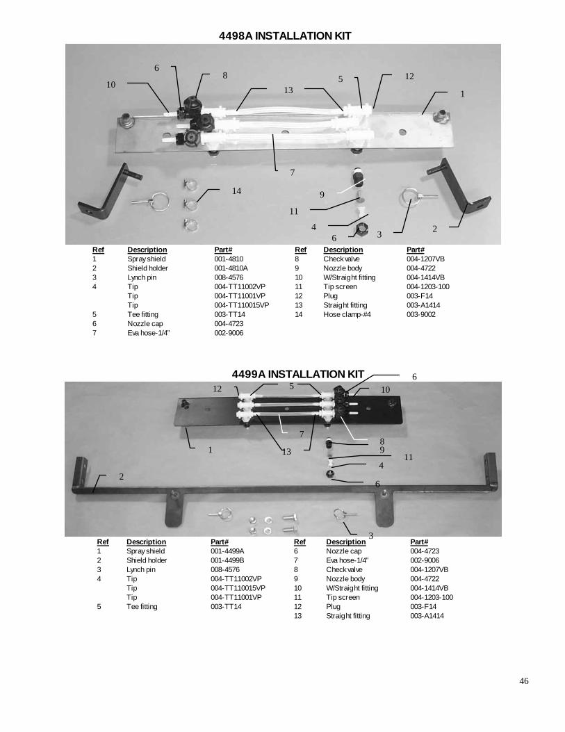
Install the spray shield-mounting bracket between the two flat vertical plates above the rotor as indicated in the picture below. Use the existing bolt holes with the hardware from the applicator kit to mount the spray shield bracket to the baler. Fasten the spray shield onto the spray shield bracket already mounted. Route hoses along the spray shield bracket towards the right side of the baler, and then back to the tank. When routing the hose avoid moving parts.
Mount the spray shield bracket between these two bolts above the rotor.
21
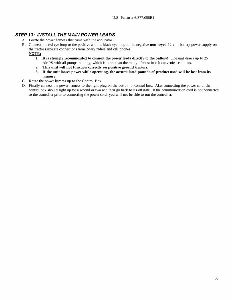
STEP 10: PLUMBING A) Use warm soapy water when connecting the three color hoses (clear, blue, and green) to the pumps located inside the pump
plate. Each color goes to a particular pump or nozzle. NOTE: The pump closest to the filter bowl and valve is pump #1 and the pump farthest from the filter bowl and valve is pump #3.
B) Route the hose from the pumps to the spray shield. Do not cut the hoses to length in case more hose length is needed later; rather, wrap the hose in an isolated location. KEEP HOSE AWAY FROM: MOVING PARTS, SHARP METAL, AND HYDRAULIC LINES. WORKING TEMPERATURE FOR THE HOSE IS 140o F AND UNDER.
C) Connect the hoses from the pumps to the spray shield as follows: Pump #1 to Orange nozzles (PUMP #1 IS CLOSET TO THE FILTER) Pump #2 to Green nozzles Pump #3 to Yellow nozzles D) Tie the hose down at secure locations on the baler using the enclosed tie straps and cable clamps. E) Wrap the hose with the coil cable in spots that are higher risk of rubbing or being caught in moving parts.
STEP 11: INSTALL THE MOUNTING BRACKET INSIDE THE TRACTOR CAB Mount the bracket in a secure area that is easy to reach in the cab and away from any obstructions. Adjust the bracket position as required to provide easy display viewing before tightening the screws.
STEP 12: INSTALL CONTROLLER CABLE HARNESS Locate the end of the main wire harness labeled Control Box installed in Step 8. Route this end of the harness in close proximity to the mounting bracket installed in Step 11. Allow enough service loop to facilitate installation and removal of the 464 control. Make sure the controller is located away from two-way radios and cell phones. Connect the main wire harness to the left plug on the bottom of the box.
Installation Kit 4500A for Hesston 4760, New Idea 7333, and Challenger LB33 with Cutter Option The spray shield assembly will be installed underneath the baler’s tongue and in front of the baler’s flywheel. Use the existing holes found on underside of tongue for mounting shield holder brackets to the position pointed to below. The bends of shield holder brackets will be pointing towards the pickup head. Use the 3/8” carriage bolts to secure to the under side of the tongue. Next place the spray shield over the pins of shield holder brackets and secure with lynch pins.
22
STEP 13: INSTALL THE MAIN POWER LEADS A. Locate the power harness that came with the applicator. B. Connect the red eye loop to the positive and the black eye loop to the negative non-keyed 12-volt battery power supply on
the tractor (separate connections from 2-way radios and cell phones). NOTE:
1. It is strongly recommended to connect the power leads directly to the battery! The unit draws up to 25 AMPS with all pumps running, which is more than the rating of most in-cab convenience outlets.
2. This unit will not function correctly on positive ground tractors. 3. If the unit looses power while operating, the accumulated pounds of product used will be lost from its
memory. C. Route the power harness up to the Control Box. D. Finally connect the power harness to the right plug on the bottom of control box. After connecting the power cord, the
control box should light up for a second or two and then go back to its off state. If the communication cord is not connected to the controller prior to connecting the power cord, you will not be able to run the controller.
U.S. Patent # 6,377,058B1
23
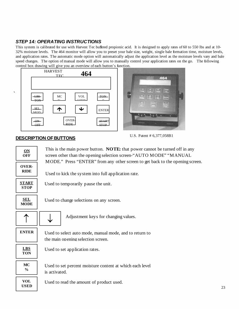
STEP 14: OPERATING INSTRUCTIONS This system is calibrated for use with Harvest Tec buffered propionic acid. It is designed to apply rates of 60 to 550 lbs and at 10-32% moisture levels. The 464 monitor will allow you to preset your bale size, weight, single bale formation time, moisture levels, and application rates. The automatic mode option will automatically adjust the application level as the moisture levels vary and bale speed changes. The option of manual mode will allow you to manually control your application rates on the go. The following control box drawing will give you an overview of each button’s function.
DESCRIPTION OF BUTTONS
OVER-RIDE Used to kick the system into full application rate.
START STOP
Used to temporarily pause the unit.
SEL MODE
Used to change selections on any screen.
↑ ↓ Adjustment keys for changing values.
ENTER
LBS TON
MC %
VOL USED
Used to select auto mode, manual mode, and to return to the main opening selection screen.
Used to set application rates.
Used to set percent moisture content at which each level is activated.
Used to read the amount of product used.
ON OFF
This is the main power button. NOTE: that power cannot be turned off in any screen other than the opening selection screen-“AUTO MODE” “MANUAL MODE.” Press “ENTER” from any other screen to get back to the opening screen.
LBS TON
MC %
VOL USED
TONS
HARVEST TEC 464
SEL MOD
ENTER
ON OFF
OVER- RIDE
START STOP
U.S. Patent # 6,377,058B1
24
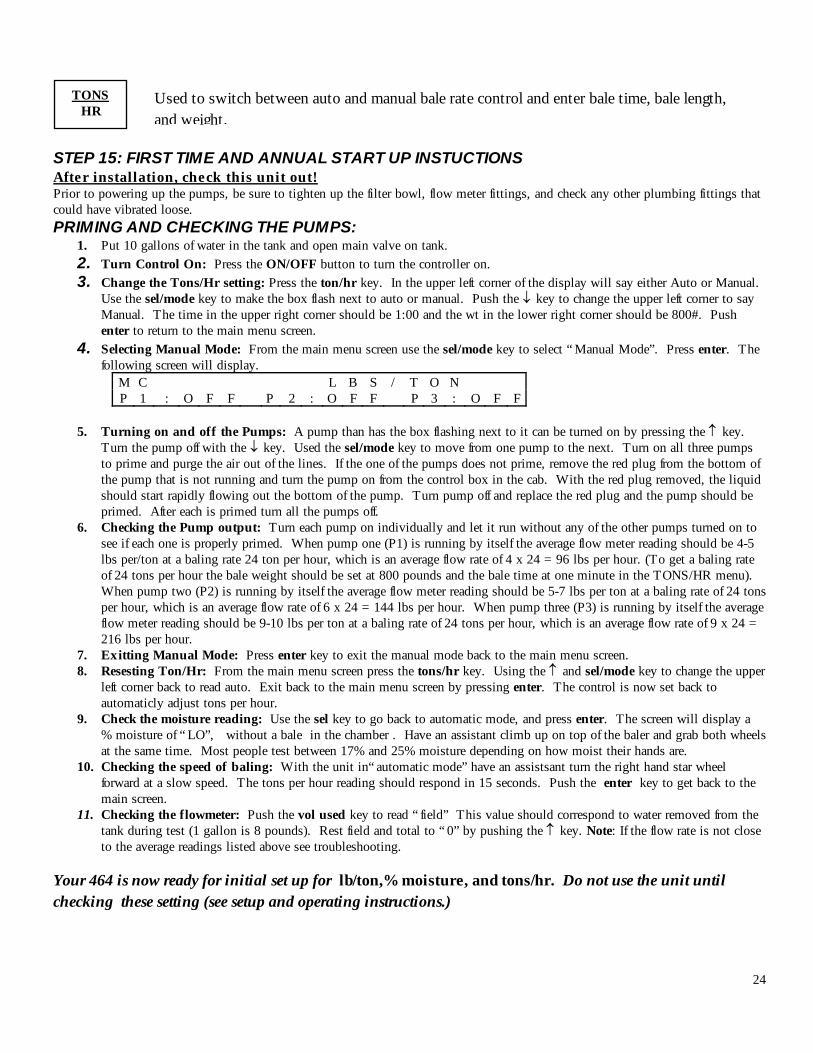
STEP 15: FIRST TIME AND ANNUAL START UP INSTUCTIONS After installation, check this unit out! Prior to powering up the pumps, be sure to tighten up the filter bowl, flow meter fittings, and check any other plumbing fittings that could have vibrated loose. PRIMING AND CHECKING THE PUMPS:
1. Put 10 gallons of water in the tank and open main valve on tank. 2. Turn Control On: Press the ON/OFF button to turn the controller on. 3. Change the Tons/Hr setting: Press the ton/hr key. In the upper left corner of the display will say either Auto or Manual.
Use the sel/mode key to make the box flash next to auto or manual. Push the ↓ key to change the upper left corner to say Manual. The time in the upper right corner should be 1:00 and the wt in the lower right corner should be 800#. Push enter to return to the main menu screen.
4. Selecting Manual Mode: From the main menu screen use the sel/mode key to select “ Manual Mode”. Press enter. The following screen will display.
M C L B S / T O N P 1 : O F F P 2 : O F F P 3 : O F F
5. Turning on and off the Pumps: A pump than has the box flashing next to it can be turned on by pressing the ↑ key.
Turn the pump off with the ↓ key. Used the sel/mode key to move from one pump to the next. Turn on all three pumps to prime and purge the air out of the lines. If the one of the pumps does not prime, remove the red plug from the bottom of the pump that is not running and turn the pump on from the control box in the cab. With the red plug removed, the liquid should start rapidly flowing out the bottom of the pump. Turn pump off and replace the red plug and the pump should be primed. After each is primed turn all the pumps off.
6. Checking the Pump output: Turn each pump on individually and let it run without any of the other pumps turned on to see if each one is properly primed. When pump one (P1) is running by itself the average flow meter reading should be 4-5 lbs per/ton at a baling rate 24 ton per hour, which is an average flow rate of 4 x 24 = 96 lbs per hour. (To get a baling rate of 24 tons per hour the bale weight should be set at 800 pounds and the bale time at one minute in the TONS/HR menu). When pump two (P2) is running by itself the average flow meter reading should be 5-7 lbs per ton at a baling rate of 24 tons per hour, which is an average flow rate of 6 x 24 = 144 lbs per hour. When pump three (P3) is running by itself the average flow meter reading should be 9-10 lbs per ton at a baling rate of 24 tons per hour, which is an average flow rate of 9 x 24 = 216 lbs per hour.
7. Exitting Manual Mode: Press enter key to exit the manual mode back to the main menu screen. 8. Resesting Ton/Hr: From the main menu screen press the tons/hr key. Using the ↑ and sel/mode key to change the upper
left corner back to read auto. Exit back to the main menu screen by pressing enter. The control is now set back to automaticly adjust tons per hour.
9. Check the moisture reading: Use the sel key to go back to automatic mode, and press enter. The screen will display a % moisture of “ LO”, without a bale in the chamber . Have an assistant climb up on top of the baler and grab both wheels at the same time. Most people test between 17% and 25% moisture depending on how moist their hands are.
10. Checking the speed of baling: With the unit in“ automatic mode” have an assistsant turn the right hand star wheel forward at a slow speed. The tons per hour reading should respond in 15 seconds. Push the enter key to get back to the main screen.
11. Checking the flowmeter: Push the vol used key to read “ field” This value should correspond to water removed from the tank during test (1 gallon is 8 pounds). Rest field and total to “ 0” by pushing the ↑ key. Note: If the flow rate is not close to the average readings listed above see troubleshooting.
Your 464 is now ready for initial set up for lb/ton,% moisture, and tons/hr. Do not use the unit until checking these setting (see setup and operating instructions.)
TONS HR
Used to switch between auto and manual bale rate control and enter bale time, bale length, and weight.
25
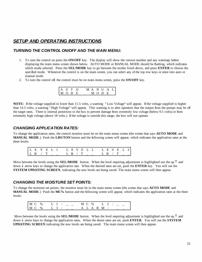
SETUP AND OPERATING INSTRUCTIONS TURNING THE CONTROL ON/OFF AND THE MAIN MENU:
1. To turn the control on press the ON/OFF key. The display will show the version number and any warnings before displaying the main menu screen shown below. AUTO MODE or MANUAL MODE should be flashing, which indicates which mode selected. Press the SEL/MODE key to go between the modes listed above, and press ENTER to choose the specified mode. Whenever the control is on the main screen, you can select any of the top row keys or enter into auto or manual mode.
2. To turn the control off, the control must be on main menu screen, press the ON/OFF key.
NOTE: If the voltage supplied in lower than 11.5 volts, a warning “ Low Voltage” will appear. If the voltage supplied is higher than 14.5 volts, a warning “ High Voltage” will appear. This warning is to alert operators that the output from the pumps may be off the target rates. There is internal protection in the box to prevent damage from extremely low voltage (below 9.5 volts) or from extremely high voltage (above 18 volts.) If the voltage is outside this range, the box will not operate.
CHANGING APPLICATION RATES: To change the application rates, the control monitor must be on the main menu screen (the screen that says AUTO MODE and MANUAL MODE.) Push the LBS/TON button and the following screen will appear, which indicates the application rates at the three levels:
L E V E L 1 L E V E L 2 L E V E L 3 L B / T _ _ L B / T _ _ L B / T _ _
Move between the levels using the SEL/MODE button. When the level requiring adjustment is highlighted use the up ↑ and down ↓ arrow keys to change the application rate. When the desired rates are set, push the ENTER key. You will see the SYSTEM UPDATING SCREEN, indicating the new levels are being saved. The main menu screen will then appear.
CHANGING THE MOISTURE SET POINTS: To change the moisture set points, the monitor must be in the main menu screen (the screen that says AUTO MODE and MANUAL MODE.) Push the MC% button and the following screen will appear, which indicates the application rates at the three levels:
M C % L 1 : _ _ M C % L 2 : _ _ M C % L 3 : _ _ A L A R M : _ _
Move between the levels using the SEL/MODE button. When the level requiring adjustment is highlighted use the up ↑ and down ↓ arrow keys to change the application rates. When the desire rates are set, push ENTER. You will see the SYSTEM UPDATING SCREEN indicating the new levels are being saved. The main menu screen will then appear.
A U T O M A N U A L M O D E M O D E

26
CHANGING BALE RATE SETTINGS: It is important to set the bale rate as close to actual baling conditions as possible. The default tons/hr reading used in the auto mode is the same bale rate used in manual bale rate mode and is based from the time it take to make a bale and bale weight. The default tons/ hr is used for the first 15 seconds of operation in auto mode and after the system is unpaused.
TO RUN IN THE AUTOMATIC BALE RATE MODE: Auto bale rate mode will automatically calculate bale rate from of the preset length, weight, and real time baling speed. Push the TON/HR button and if the bale rate is currently in manual mode, the following screen will appear.
M A N U A L T / H R T I M E _ _ _ _ L E N G T H N A W T : _ _ _ _ #
Use the SELECT/MODE key move the blinking box over to the time. Use the ↑ and ↓ to change the time to the actual time it takes make a bale. Use the SELECT/MODE key to move the blinking box is next to the manual in the upper left corner. Press the up ↑ key to change it to auto in the upper left corner. The following screen will appear:
A U T O T / H R T I M E N A L E N G T H _ _ I N W T : _ _ _ _ #
The length is the bale length measured in inches and the bale weight (WT:) is in pounds. Use the SEL/MODE button to move between BALE LENGTH and BALE WEIGHT. Use the up ↑ and down ↓ arrow keys to change the values. When the desired values are set, push ENTER. You will see the SYSTEM UPDATING SCREEN indicating the new levels are being saved. The main screen will then appear. The displayed baling rate value, while running in automatic mode, will display the baling rate that is updated every 15 seconds.
TO RUN IN THE M ANUAL BALE RATE M ODE: Manual bale rate will manually calculate the bale rate from the preset time of baling and weight. Push the TON/HR button and if the bale rate is currently in auto mode, the following screen will appear.
To change bale rate sensing into manual mode, press the ↓ key, when Auto mode is flashing and the following screen will appear: The time to make a bale and the bale weight need to be inputted on this screen. The bale time is in seconds. Use Sel/Mode key to
move between Time and Weight. Use the ↑ and ↓ keys to change the values. When the desired values are set, push ENTER. You will see the SYSTEM UPDATING SCREEN indicating the new levels are being saved. The main screen will then appear. AUTOMATIC MODE OR MANUAL MODE DESCRIPTIONS AUTO MODE will automatically apply product to the hay based on the moisture content sensed by the star wheels and the operators presets (to adjust see changing application rates, changing moisture set points and changing bale rate settings).
A U T O T / H R T I M E N A L E N G T H _ 9 6 I N W T : _ _ _ _ #
M A N U A L T / H R T I M E _ _ _ _ L E N G T H N A W T : _ _ _ _ #
27
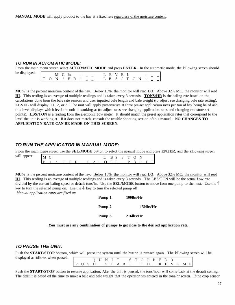
MANUAL MODE will apply product to the hay at a fixed rate regardless of the moisture content. TO RUN IN AUTOM ATIC M ODE: From the main menu screen select AUTOMATIC MODE and press ENTER. In the automatic mode, the following screen should be displayed: MC% is the percent moisture content of the hay. Below 10%, the monitor will read LO. Above 32% MC, the monitor will read HI. This reading is an average of multiple readings and is taken every 3 seconds. TONS/HR is the baling rate based on the calculations done from the bale rate sensors and user inputted bale length and bale weight (to adjust see changing bale rate setting). LEVEL will display 0,1, 2, or 3. The unit will apply preservative at three pre-set application rates per ton of hay being baled and this level displays which level the unit is working at (to adjust rates see changing application rates and changing moisture set points). LBS/TON is a reading from the electronic flow meter. It should match the preset application rates that correspond to the level the unit is working at. If it does not match, consult the trouble shooting section of this manual. NO CHANGES TO APPLICATION RATE CAN BE MADE ON THIS SCREEN.
TO RUN THE APPLICATOR IN MANUAL MODE: From the main menu screen use the SEL/MODE button to select the manual mode and press ENTER, and the following screen will appear. MC% is the percent moisture content of the hay. Below 10%, the monitor will read LO. Above 32% MC, the monitor will read HI. This reading is an average of multiple readings and is taken every 3 seconds. The LBS/TON will be the actual flow rate divided by the current baling speed or default tons/hr. Use the SEL/MODE button to move from one pump to the next. Use the ↑ key to turn the selected pump on. Use the ↓ key to turn the selected pump off. Manual application rates are fixed at:
Pump 1 100lbs/Hr Pump 2 150lbs/Hr Pump 3 216lbs/Hr
You must use any combination of pumps to get close to the desired application rate.
TO PAUSE THE UNIT: Push the START/STOP bottom, which will pause the system until the button is pressed again. The following screen will be displayed as follows when paused: Push the START/STOP button to resume application. After the unit is paused, the tons/hour will come back at the default setting. The default is based off the time to make a bale and bale weight that the operator has entered in the tons/hr screen. If the crop sensor
M C % : _ _ L E V E L : _ _ T O N / H R : _ _ L B S / T O N : _ _
M C L B S / T O N P 1 : O F F P 2 : O F F P 3 O F F
( U N I T S T O P P E D ) P U S H S T A R T T O R E S U M E
28
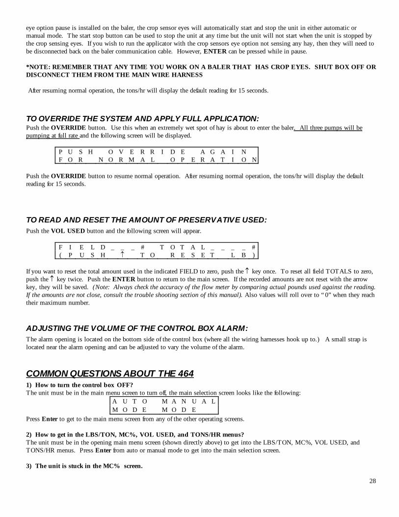
eye option pause is installed on the baler, the crop sensor eyes will automatically start and stop the unit in either automatic or manual mode. The start stop button can be used to stop the unit at any time but the unit will not start when the unit is stopped by the crop sensing eyes. If you wish to run the applicator with the crop sensors eye option not sensing any hay, then they will need to be disconnected back on the baler communication cable. However, ENTER can be pressed while in pause. *NOTE: REMEMBER THAT ANY TIME YOU WORK ON A BALER THAT HAS CROP EYES. SHUT BOX OFF OR DISCONNECT THEM FROM THE MAIN WIRE HARNESS After resuming normal operation, the tons/hr will display the default reading for 15 seconds. TO OVERRIDE THE SYSTEM AND APPLY FULL APPLICATION: Push the OVERRIDE button. Use this when an extremely wet spot of hay is about to enter the baler. All three pumps will be pumping at full rate and the following screen will be displayed.
P U S H O V E R R I D E A G A I N F O R N O R M A L O P E R A T I O N
Push the OVERRIDE button to resume normal operation. After resuming normal operation, the tons/hr will display the default reading for 15 seconds.
TO READ AND RESET THE AMOUNT OF PRESERVATIVE USED: Push the VOL USED button and the following screen will appear.
F I E L D _ _ _ # T O T A L _ _ _ _ # ( P U S H ↑ T O R E S E T L B )
If you want to reset the total amount used in the indicated FIELD to zero, push the ↑ key once. To reset all field TOTALS to zero, push the ↑ key twice. Push the ENTER button to return to the main screen. If the recorded amounts are not reset with the arrow key, they will be saved. (Note: Always check the accuracy of the flow meter by comparing actual pounds used against the reading. If the amounts are not close, consult the trouble shooting section of this manual). Also values will roll over to “ 0” when they reach their maximum number.
ADJUSTING THE VOLUME OF THE CONTROL BOX ALARM: The alarm opening is located on the bottom side of the control box (where all the wiring harnesses hook up to.) A small strap is located near the alarm opening and can be adjusted to vary the volume of the alarm. COMMON QUESTIONS ABOUT THE 464 1) How to turn the control box OFF? The unit must be in the main menu screen to turn off, the main selection screen looks like the following:
A U T O M A N U A L M O D E M O D E
Press Enter to get to the main menu screen from any of the other operating screens. 2) How to get in the LBS/TON, MC%, VOL USED, and TONS/HR menus? The unit must be in the opening main menu screen (shown directly above) to get into the LBS/TON, MC%, VOL USED, and TONS/HR menus. Press Enter from auto or manual mode to get into the main selection screen. 3) The unit is stuck in the MC% screen.
29
In the MC% screen, level 1 must be less than level 2, and level 2 must be less than level 3. For example, if level 1 is set at 16, level 2 must be set at 17 or higher, and level 3 must be set higher than level 2. 4) How does OVERRIDE work? Override turns on all three pumps at full output. 5) The flow meter reading is more or less than the programmed level set in the box. Some variation in flow meter readings compared to the programmed set-point is normal due to factory tolerances on the pump motors as well as varying tractor voltages inputted to the control box. The flow meter reading is an accurate measure of how much is actually being applied so adjust the set-points in the box to try and attain the desired flow meter reading. 6) Why don’t all the pumps turn on even at higher application rates? The selection of what pumps turn on when are automatically controlled by the control box’s flow rate look up chart. Thus, not all the pumps turn on at once and the combination of what pumps turn on when is automatically controlled by the software. If you want to make sure all three pumps are working, run the unit in auto mode and hit override. This will turn all three pumps on at once at their maximum output. 7) The moisture content displays “LO” or “HI” all the time. When the moisture content display does not change frequently while baling, there is likely a faulty star wheel connection. One of the first places to check is inside the white star wheel block. Check to see if the electronic swivel is in the star wheel shaft and check to see that the star wheel shaft is not working out of the block. Also, check all star wheel wires and connectors to see if there is a continuity problem.
ROUTINE MAINTENANCE 1) Clean the tip strainers and main strainer every 10 hours of operation or more frequently if required. 2) Depending on the product being used, the system may need to be flushed with water at a regular interval(consult with
manufacturer of the chemical.) If Harvest Tec product is being used, flushing is not necessary. 3) Although the pump can run dry, extended operation of a dry pump will increase wear. Watch the preservative level in the tank. 4) Cover the electronic cab control box on open station tractors if left outside. 5) Pump performance may start to decline after 400 hours (10,000 bales on large square balers) of use. Rebuilding the pump is a
simple procedure if the motor is not damaged. Order pump rebuilding kit #007-4581 for the automatic unit. 6) Check and clean wire connections at beginning of each cutting.
WINTER STORAGE
1) It is okay to leave Harvest Tec preservative in your system down to 50 below zero. If you are not using Harvest Tec preservative you must thoroughly flush the system with water.
2) Remove the filter bowl and run dry until the water has cleared out of the intake side. 3) Remove the red plug from the bottom of the pump, drain, and run the pump for 30 seconds or until it is dry. 4) Drain all lines. 5) Never use oils or alcohol based anti-freeze in the system. 6) For spring start-up, or anytime the pump is frozen, turn off the power immediately to avoid burning the motor out. The pump
head can be disassembled and freed or rebuilt in most cases. 7) ****When using other products other than Harvest Tec product, make sure to flush the system thoroughly!
30
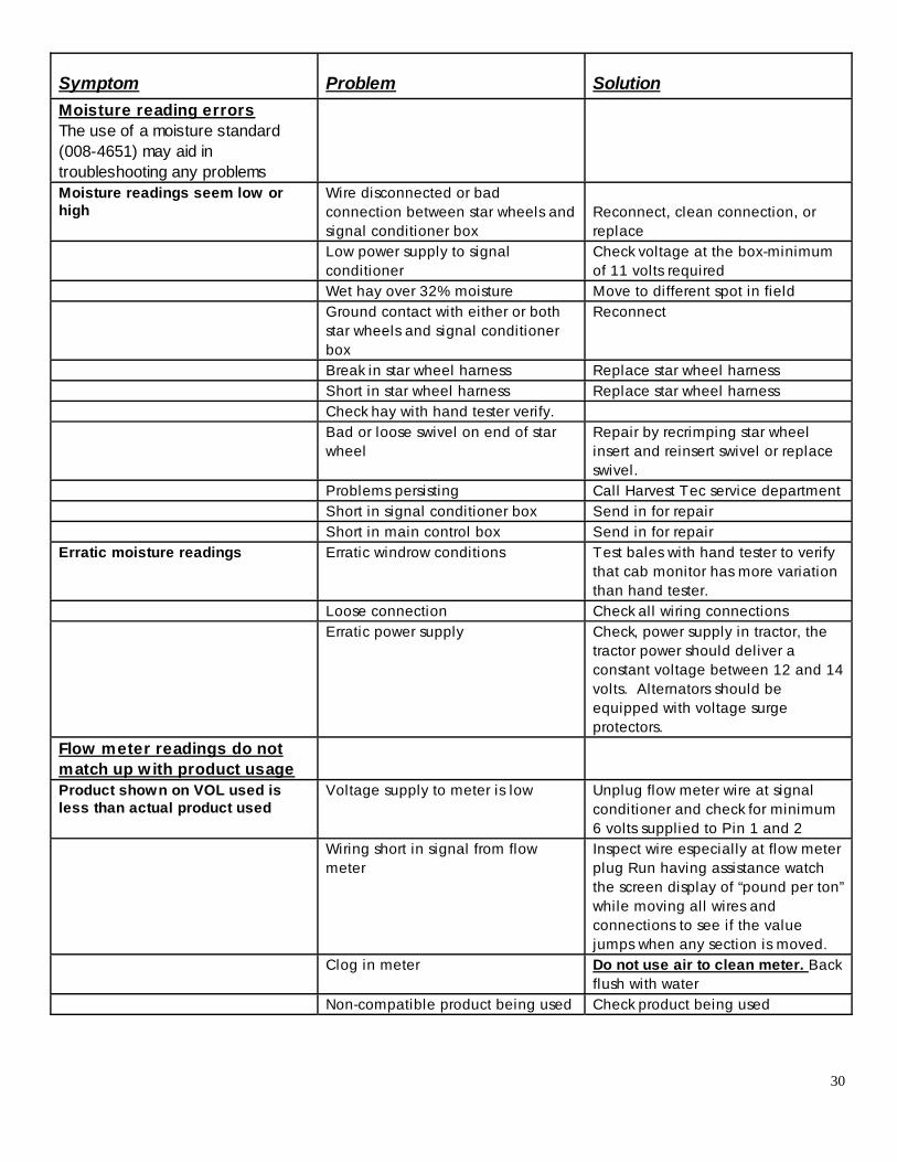
Symptom Problem Solution Moisture reading errors The use of a moisture standard (008-4651) may aid in troubleshooting any problems
Moisture readings seem low or high
Wire disconnected or bad connection between star wheels and signal conditioner box
Reconnect, clean connection, or replace
Low power supply to signal conditioner
Check voltage at the box-minimum of 11 volts required
Wet hay over 32% moisture Move to different spot in field Ground contact with either or both
star wheels and signal conditioner box
Reconnect
Break in star wheel harness Replace star wheel harness Short in star wheel harness Replace star wheel harness Check hay with hand tester verify. Bad or loose swivel on end of star
wheel Repair by recrimping star wheel insert and reinsert swivel or replace swivel.
Problems persisting Call Harvest Tec service department Short in signal conditioner box Send in for repair Short in main control box Send in for repair Erratic moisture readings Erratic windrow conditions Test bales with hand tester to verify
that cab monitor has more variation than hand tester.
Loose connection Check all wiring connections Erratic power supply Check, power supply in tractor, the
tractor power should deliver a constant voltage between 12 and 14 volts. Alternators should be equipped with voltage surge protectors.
Flow meter readings do not match up with product usage
Product shown on VOL used is less than actual product used
Voltage supply to meter is low Unplug flow meter wire at signal conditioner and check for minimum 6 volts supplied to Pin 1 and 2
Wiring short in signal from flow meter
Inspect wire especially at flow meter plug Run having assistance watch the screen display of “pound per ton” while moving all wires and connections to see if the value jumps when any section is moved.
Clog in meter Do not use air to clean meter. Back flush with water
Non-compatible product being used Check product being used
31
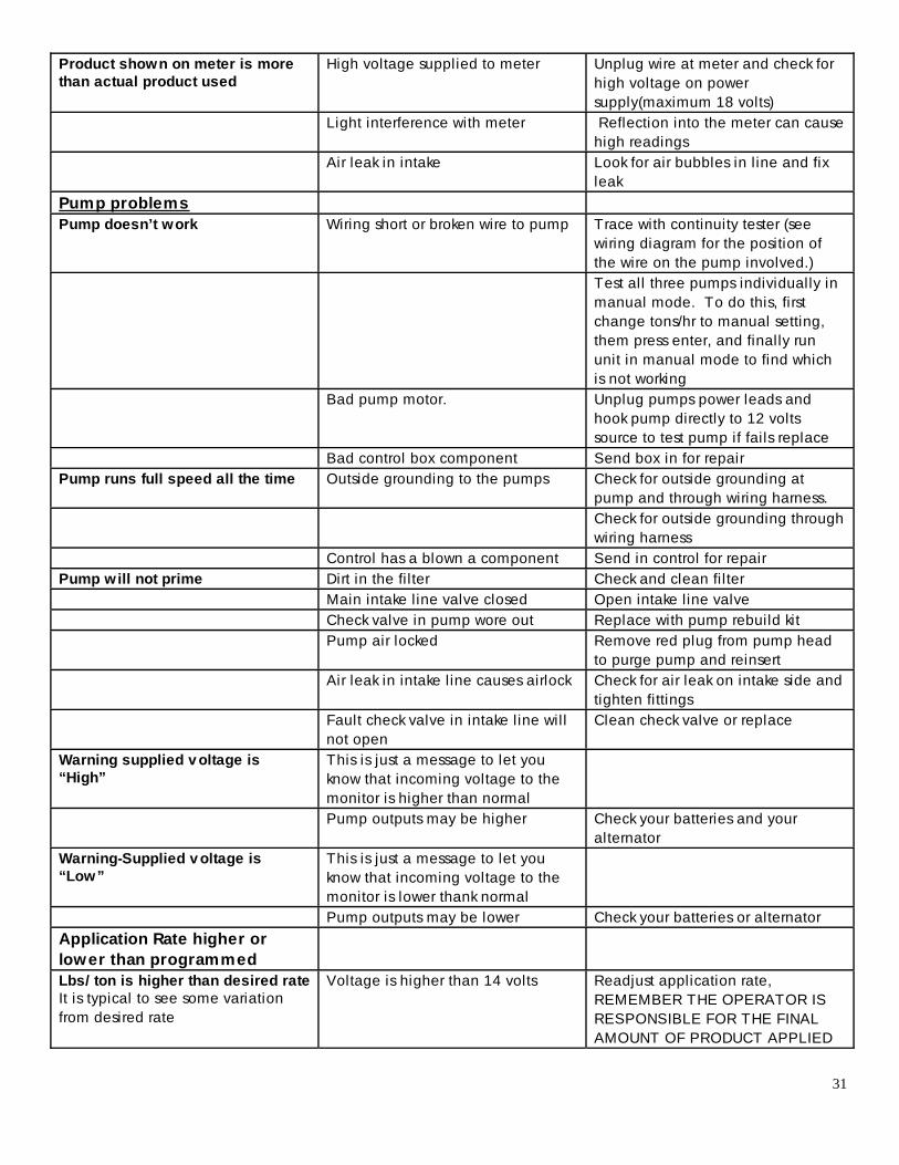
Product shown on meter is more than actual product used
High voltage supplied to meter Unplug wire at meter and check for high voltage on power supply(maximum 18 volts)
Light interference with meter Reflection into the meter can cause high readings
Air leak in intake Look for air bubbles in l ine and fix leak
Pump problems Pump doesn’t work Wiring short or broken wire to pump Trace with continuity tester (see
wiring diagram for the position of the wire on the pump involved.)
Test all three pumps individually in manual mode. To do this, first change tons/hr to manual setting, them press enter, and finally run unit in manual mode to find which is not working
Bad pump motor. Unplug pumps power leads and hook pump directly to 12 volts source to test pump if fails replace
Bad control box component Send box in for repair Pump runs full speed all the time Outside grounding to the pumps Check for outside grounding at
pump and through wiring harness. Check for outside grounding through
wiring harness Control has a blown a component Send in control for repair Pump will not prime Dirt in the fi lter Check and clean fi lter Main intake line valve closed Open intake line valve Check valve in pump wore out Replace with pump rebuild kit Pump air locked Remove red plug from pump head
to purge pump and reinsert Air leak in intake line causes airlock Check for air leak on intake side and
tighten fittings Fault check valve in intake line will
not open Clean check valve or replace
Warning supplied v oltage is “High”
This is just a message to let you know that incoming voltage to the monitor is higher than normal
Pump outputs may be higher Check your batteries and your alternator
Warning-Supplied v oltage is “Low”
This is just a message to let you know that incoming voltage to the monitor is lower thank normal
Pump outputs may be lower Check your batteries or alternator Application Rate higher or lower than programmed
Lbs/ ton is higher than desired rate It is typical to see some variation from desired rate
Voltage is higher than 14 volts Readjust application rate, REMEMBER THE OPERATOR IS RESPONSIBLE FOR THE FINAL AMOUNT OF PRODUCT APPLIED
32
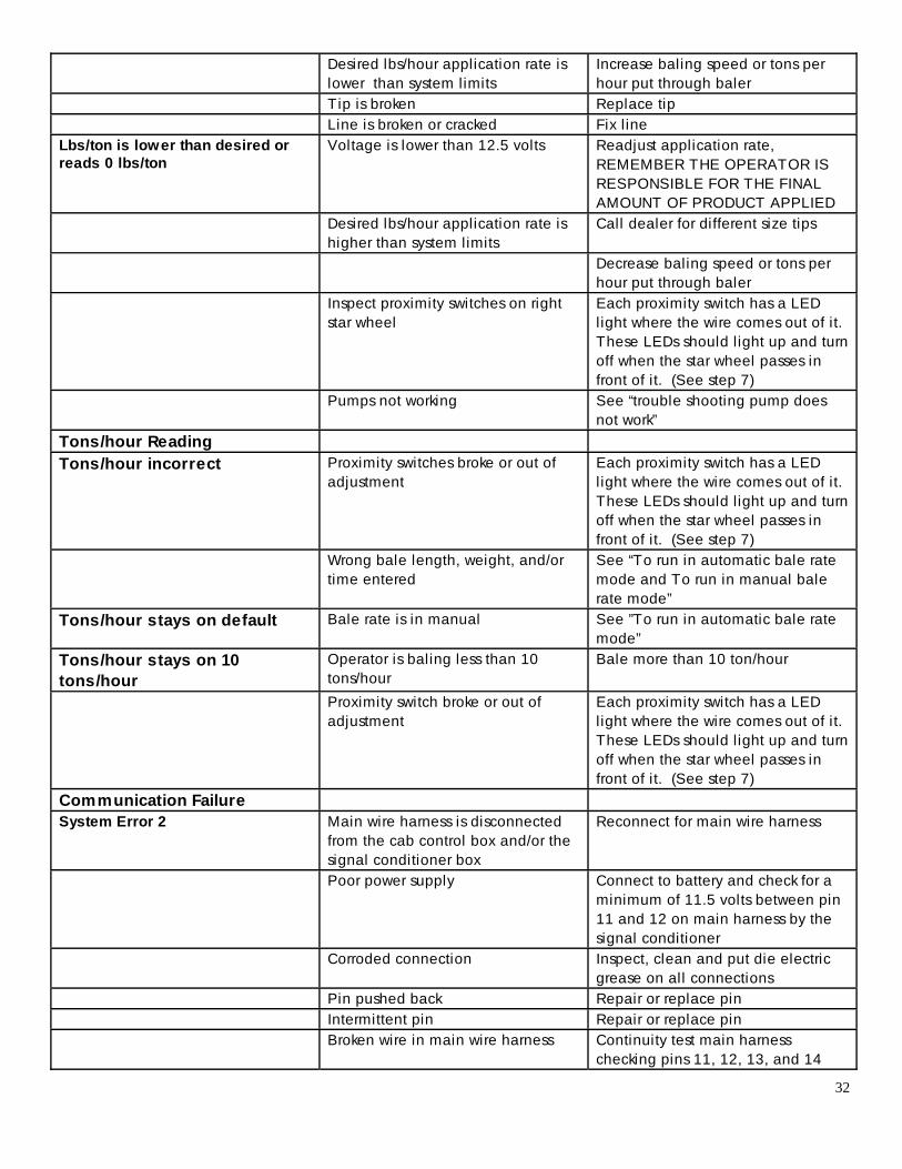
Desired lbs/hour application rate is lower than system limits
Increase baling speed or tons per hour put through baler
Tip is broken Replace tip Line is broken or cracked Fix l ine Lbs/ton is lower than desired or reads 0 lbs/ton
Voltage is lower than 12.5 volts Readjust application rate, REMEMBER THE OPERATOR IS RESPONSIBLE FOR THE FINAL AMOUNT OF PRODUCT APPLIED
Desired lbs/hour application rate is higher than system limits
Call dealer for different size tips
Decrease baling speed or tons per hour put through baler
Inspect proximity switches on right star wheel
Each proximity switch has a LED light where the wire comes out of it. These LEDs should light up and turn off when the star wheel passes in front of it. (See step 7)
Pumps not working See “trouble shooting pump does not work”
Tons/hour Reading Tons/hour incorrect Proximity switches broke or out of
adjustment Each proximity switch has a LED light where the wire comes out of it. These LEDs should light up and turn off when the star wheel passes in front of it. (See step 7)
Wrong bale length, weight, and/or time entered
See “To run in automatic bale rate mode and To run in manual bale rate mode”
Tons/hour stays on default Bale rate is in manual See ”To run in automatic bale rate mode”
Tons/hour stays on 10 tons/hour
Operator is baling less than 10 tons/hour
Bale more than 10 ton/hour
Proximity switch broke or out of adjustment
Each proximity switch has a LED light where the wire comes out of it. These LEDs should light up and turn off when the star wheel passes in front of it. (See step 7)
Communication Failure System Error 2 Main wire harness is disconnected
from the cab control box and/or the signal conditioner box
Reconnect for main wire harness
Poor power supply Connect to battery and check for a minimum of 11.5 volts between pin 11 and 12 on main harness by the signal conditioner
Corroded connection Inspect, clean and put die electric grease on all connections
Pin pushed back Repair or replace pin Intermittent pin Repair or replace pin Broken wire in main wire harness Continuity test main harness
checking pins 11, 12, 13, and 14
33
Wires in main wire harness are shorting between each other
Test and replace
Defective flow meter Unplug all wire harnesses from signal conditioner except main harness and reconnect each one at a time
Faulty control box or signal conditioner box
Send in for repair
Other System leaks product out of tips after shut down
Dirty or defective check valves on spray shield
Clean or replace valves
Part of display is missing Defective display screen Send in for repair Box will not power up No power supplied Check to make sure a least 12 volts
is supplied Blown external fuse Check and replace inline 25 amp
fuse Blown internal fuse Carefully check and replace the
internal 3 and 20 amp fuse Blown fuses Short in main wire harness or crop-
eye harness Inspect wire for pinched, cut, broken, or exposed wire
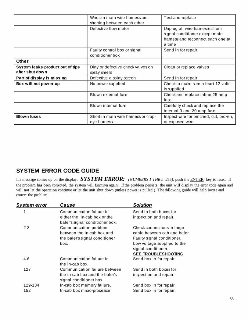
SYSTEM ERROR CODE GUIDE If a message comes up on the display, SYSTEM ERROR: (NUMBERS 1 THRU 255), push the ENTER key to reset. If the problem has been corrected, the system will function again. If the problem persists, the unit will display the error code again and will not let the operation continue or let the unit shut down (unless power is pulled.) The following guide will help locate and correct the problem.
System error Cause Solution 1 Communication failure in Send in both boxes for either the in-cab box or the inspection and repair. baler’s signal conditioner box. 2-3 Communication problem Check connections in large between the in-cab box and cable between cab and baler. the baler’s signal conditioner Faulty signal conditioner. box. Low voltage supplied to the signal conditioner. SEE TROUBLESHOOTING 4-6 Communication failure in Send box in for repair. the in-cab box. 127 Communication failure between Send in both boxes for the in-cab box and the baler’s inspection and repair. signal conditioner box. 129-134 In-cab box memory failure. Send box in for repair. 152 In-cab box micro-processor Send box in for repair.
34
failure. 153 Bale rate calculation came in Run the unit in the manual too high or too low. baling rate mode on the TONS/HR key until baling resumes at a rate between 10 and 100 tons per hour. 154 In-cab box voltage detection Send box in for repair. failure. 255 Internal failure in either the Send in both boxes for the in-cab box or the baler’s inspection and repair. signal conditioner box.
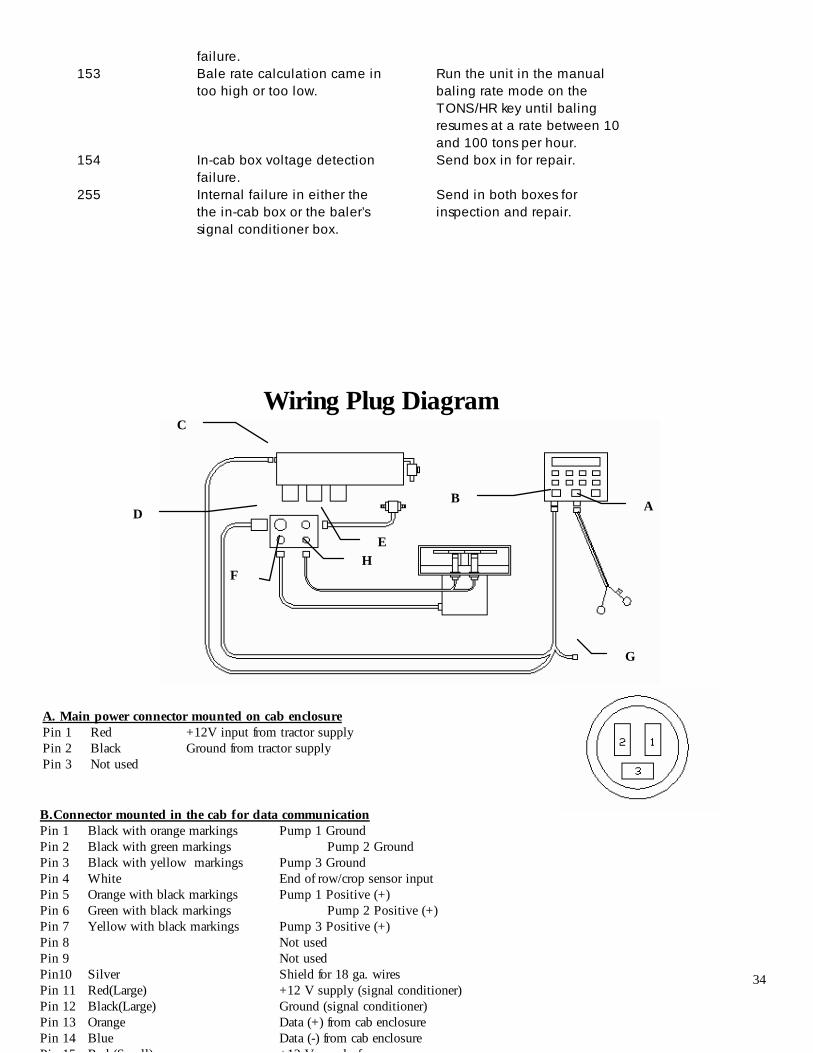
Wiring Plug Diagram
A. Main power connector mounted on cab enclosure Pin 1 Red +12V input from tractor supply Pin 2 Black Ground from tractor supply Pin 3 Not used
B.Connector mounted in the cab for data communication Pin 1 Black with orange markings Pump 1 Ground Pin 2 Black with green markings Pump 2 Ground Pin 3 Black with yellow markings Pump 3 Ground Pin 4 White End of row/crop sensor input Pin 5 Orange with black markings Pump 1 Positive (+) Pin 6 Green with black markings Pump 2 Positive (+) Pin 7 Yellow with black markings Pump 3 Positive (+) Pin 8 Not used Pin 9 Not used Pin10 Silver Shield for 18 ga. wires Pin 11 Red(Large) +12 V supply (signal conditioner) Pin 12 Black(Large) Ground (signal conditioner) Pin 13 Orange Data (+) from cab enclosure Pin 14 Blue Data (-) from cab enclosure Pin 15 Red (Small) +12 V s ppl for crop sensors
C
D
F H
E
B A
G
35
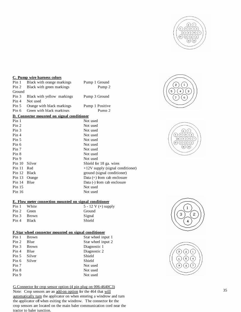
C. Pump wire harness colors Pin 1 Black with orange markings Pump 1 Ground Pin 2 Black with green markings Pump 2 Ground Pin 3 Black with yellow markings Pump 3 Ground Pin 4 Not used Pin 5 Orange with black markings Pump 1 Positive Pin 6 Green with black markings Pump 2 Positive Pin 7 Yellow with black markings Pump 3 Positive D. Connector mounted on signal conditioner Pin 1 Not used Pin 2 Not used Pin 3 Not used Pin 4 Not used Pin 5 Not used Pin 6 Not used Pin 7 Not used Pin 8 Not used Pin 9 Not used Pin 10 Silver Shield for 18 ga. wires Pin 11 Red +12V supply (signal conditioner) Pin 12 Black ground (signal conditioner) Pin 13 Orange Data (+) from cab enclosure Pin 14 Blue Data (-) from cab enclosure Pin 15 Not used Pin 16 Not used
E. Flow meter connection mounted on signal conditioner Pin 1 White 5 - 12 V (+) supply Pin 2 Green Ground Pin 3 Brown Signal Pin 4 Black Shield
F.Star wheel connector mounted on signal conditioner Pin 1 Brown Star wheel input 1 Pin 2 Blue Star wheel input 2 Pin 3 Brown Diagnostic 1 Pin 4 Blue Diagnostic 2 Pin 5 Silver Shield Pin 6 Silver Shield Pin 7 Not used Pin 8 Not used Pin 9 Not used
G.Connector for crop sensor option (4 pin plug on 006-4640C3) Note: Crop sensors are an add-on option for the 464 that will automatically turn the applicator on when entering a windrow and turn the applicator off when exiting the windrow. The connector for the crop sensors are located on the main baler communication cord near the tractor to baler junction.
36
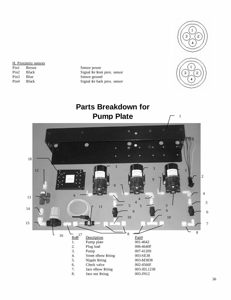
Ref# Description Part# 1. Pump plate 001-4642 2. Plug lead 006-4640F 3. Pump 007-4120S 4. Street elbow fitting 003-SE38 5. Nipple fitting 003-M3838 6. Check valve 002-4566F 7. Jaco elbow fitting 003-JEL1238 8. Jaco nut fitting 003-JN12
B
Parts Breakdown for Pump Plate 1
2
3
4
5
6
7
8
9 9
9 4
4
3 3
5
8
10 10
6 6 11
12
13
14
15
16 17
18
3
5
H. Proximity sensors Pin1 Brown Sensor power Pin2 Black Signal for front prox. sensor Pin3 Blue Sensor ground Pin4 Black Signal for back prox. sensor
37
9. Elbow fitting 003-EL3814 10. Jaco tee fitting 003-JT3838T 11. Flow meter assembly 006-4725A 12. Straight fitting 003-A1212 13. Ball valve 002-2212 14. Nipple fitting 003-M1212 15. Street elbow fitting 003-SE12 16. Filter bowl (100 mesh filter) 002-4315 17. Straight jaco fitting 003-JA1212 18. Signal conditioner 006-4650C
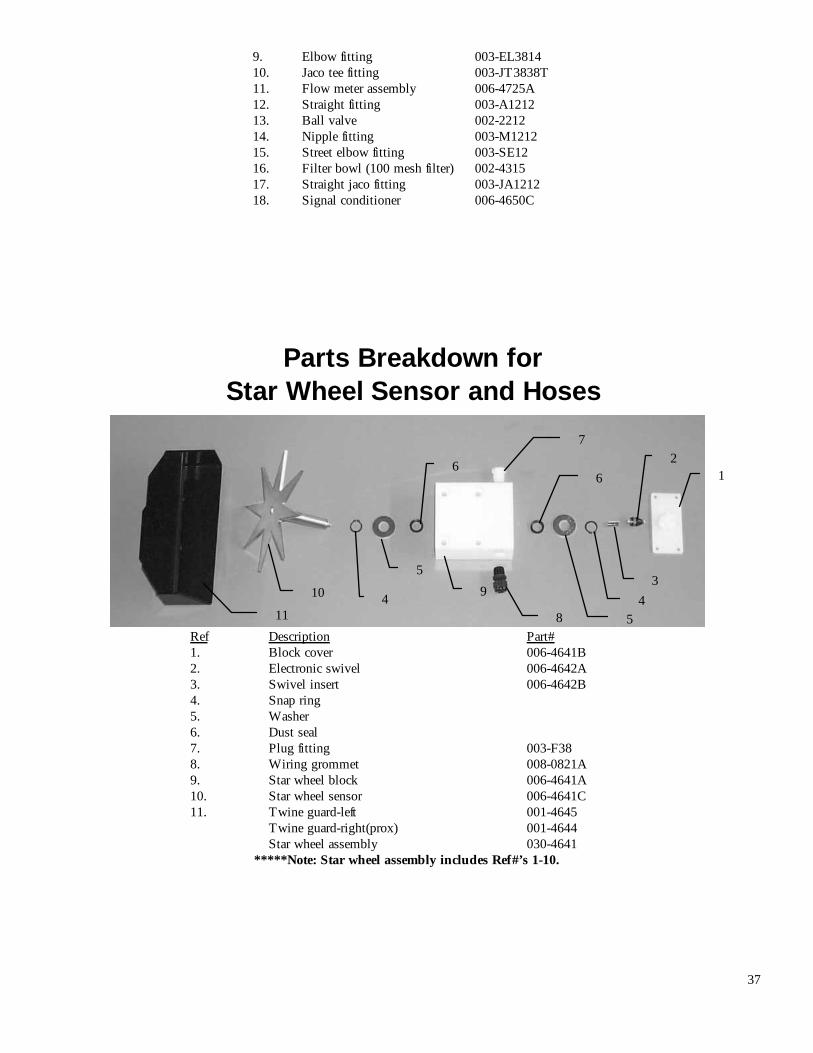
Ref Description Part# 1. Block cover 006-4641B 2. Electronic swivel 006-4642A 3. Swivel insert 006-4642B 4. Snap ring 5. Washer 6. Dust seal 7. Plug fitting 003-F38 8. Wiring grommet 008-0821A 9. Star wheel block 006-4641A 10. Star wheel sensor 006-4641C 11. Twine guard-left 001-4645 Twine guard-right(prox) 001-4644 Star wheel assembly 030-4641
*****Note: Star wheel assembly includes Ref#’s 1-10.
Parts Breakdown for Star Wheel Sensor and Hoses
1 2
3 4
5
6
7
8
9
6
5
4 10
11
38
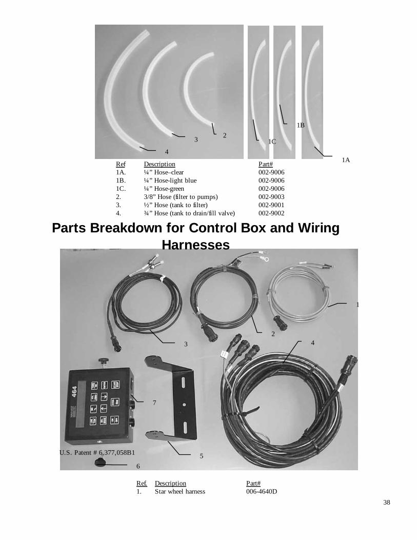
Ref. Description Part# 1. Star wheel harness 006-4640D
Ref Description Part# 1A. ¼” Hose–clear 002-9006 1B. ¼” Hose-light blue 002-9006 1C. ¼” Hose-green 002-9006 2. 3/8” Hose (filter to pumps) 002-9003 3. ½” Hose (tank to filter) 002-9001 4. ¾” Hose (tank to drain/fill valve) 002-9002
Parts Breakdown for Control Box and Wiring Harnesses
1A
2 3
1
2 3 4
5 6
7
U.S. Patent # 6,377,058B1
1B
1C 4

39
2. Power supply harness 006-4640A 3. Proximity sensor and harness 006-7202 4. Main control harness 006-4640C3 5. Control box bracket 001-2012G 6. Control box knobs 008-0923 7. 464 control box 006-4650A
40
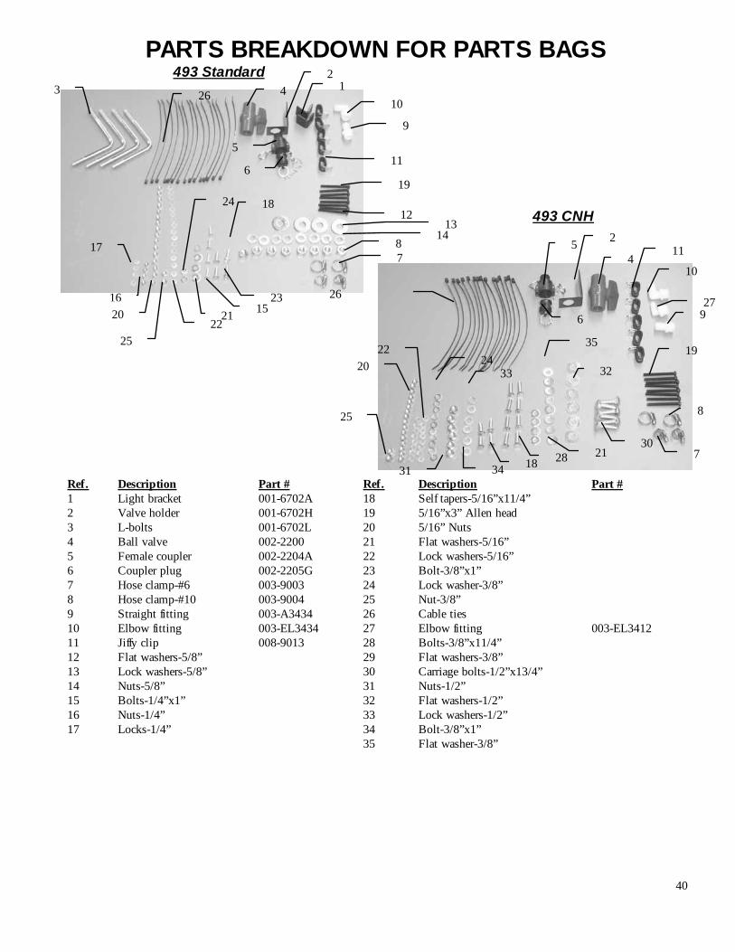
Ref. Description Part # Ref. Description Part # 1 Light bracket 001-6702A 18 Self tapers-5/16”x11/4” 2 Valve holder 001-6702H 19 5/16”x3” Allen head 3 L-bolts 001-6702L 20 5/16” Nuts 4 Ball valve 002-2200 21 Flat washers-5/16” 5 Female coupler 002-2204A 22 Lock washers-5/16” 6 Coupler plug 002-2205G 23 Bolt-3/8”x1” 7 Hose clamp-#6 003-9003 24 Lock washer-3/8” 8 Hose clamp-#10 003-9004 25 Nut-3/8” 9 Straight fitting 003-A3434 26 Cable ties 10 Elbow fitting 003-EL3434 27 Elbow fitting 003-EL3412 11 Jiffy clip 008-9013 28 Bolts-3/8”x11/4” 12 Flat washers-5/8” 29 Flat washers-3/8” 13 Lock washers-5/8” 30 Carriage bolts-1/2”x13/4” 14 Nuts-5/8” 31 Nuts-1/2” 15 Bolts-1/4”x1” 32 Flat washers-1/2” 16 Nuts-1/4” 33 Lock washers-1/2” 17 Locks-1/4” 34 Bolt-3/8”x1” 35 Flat washer-3/8”
PARTS BREAKDOWN FOR PARTS BAGS 1
2
2
3 4
4
5
5
6
6
7
7
8
8
9
9
10
11
12 13
14
15 16
17
18 19
20 22
21 23
24
25
26
493 Standard
493 CNH
27
10
11
28 34
24 35
25
19
31
32 33
18
30
20
21
22
26
41
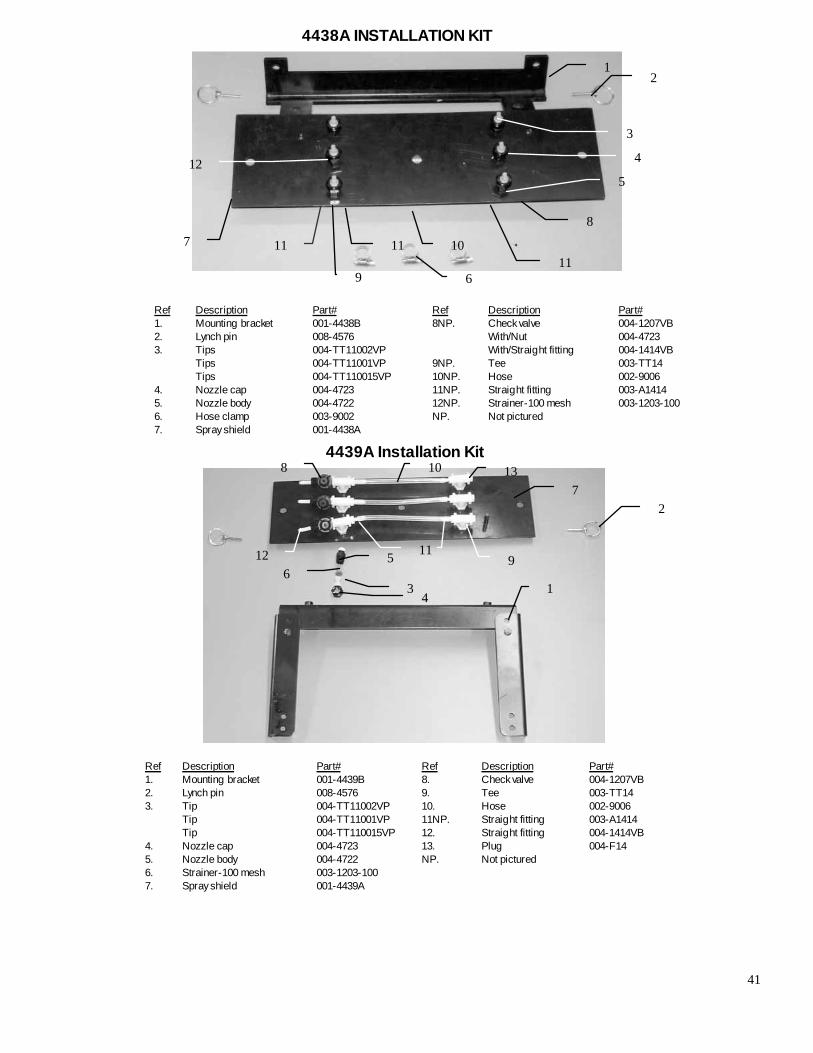
Ref Description Part# Ref Description Part# 1. Mounting bracket 001-4438B 8NP. Check valve 004-1207VB 2. Lynch pin 008-4576 With/Nut 004-4723 3. Tips 004-TT11002VP With/Straight fitting 004-1414VB Tips 004-TT11001VP 9NP. Tee 003-TT14 Tips 004-TT110015VP 10NP. Hose 002-9006 4. Nozzle cap 004-4723 11NP. Straight fitting 003-A1414 5. Nozzle body 004-4722 12NP. Strainer-100 mesh 003-1203-100 6. Hose clamp 003-9002 NP. Not pictured 7. Spray shield 001-4438A
Ref Description Part# Ref Description Part# 1. Mounting bracket 001-4439B 8. Check valve 004-1207VB 2. Lynch pin 008-4576 9. Tee 003-TT14 3. Tip 004-TT11002VP 10. Hose 002-9006 Tip 004-TT11001VP 11NP. Straight fitting 003-A1414 Tip 004-TT110015VP 12. Straight fitting 004-1414VB 4. Nozzle cap 004-4723 13. Plug 004-F14 5. Nozzle body 004-4722 NP. Not pictured 6. Strainer-100 mesh 003-1203-100 7. Spray shield 001-4439A
4438A INSTALLATION KIT
1
2
3
4
5
6
7 11
9 11
11 10
8
12
2
3 4
5 6
7
8
9
10
11 12
13
1
4439A Installation Kit
42
Ref Description Part# 1. Shield holder 001-4421B 2. Shield clip 001-4421A 3. Bolts-5/16”x2 1/4” 4. #4 Hose clamp 003-9003 5 Lynch pins 008-4576 6. Tips 004-TT11002VP Tips 004-TT11001VP Tips 004-TT110015VP 7. Eva hose-1/4” 002-9006 8. Strainer-100 mesh 004-1203-100 9. Nozzle cap 004-4723
Ref Description Part# 10. Nozzle body 004-4722 11. Spray shield 001-4421 12. Plug 003-F14 13. Tee 003-TT14 14. Straight fitting 003-A1414 15. Check valve 004-1207VB 16. Straight fitting 004-A1414VB 17. Lock washers-5/16” 18NP. Spacer plate 004-6702S
10
4490A INSTALLATION KIT
4491A INSTALLATION KIT
Ref Description Part # 11. ¼” lock washers 12. ¼” nuts 13. Plug 003-F14 14. Tee 003-TT14 15. Straight fitting 003-A1414 16. Eva hose- ¼” 002-9006 17. Nozzle body 004-4722 18. Check valve 004-1207VB 19. Nut 004-4723 20. Straight fitting 003-A1414VB NP. Not pictured
Ref Description Part # 1. Lynch pin 008-4576 2. Shield holder 001-4422B 3. Spray shield 001-4422 4. Tip 004-TT11002VP
Tip 004-TT11001VP Tip 004-TT110015VP
5. Nozzle cap 004-4723 6NP. Strainer-100mesh 004-1203-100 7. Backing plates 001-4422A 8. #4 Hose clamps 003-9002 9. Bolts-¼”x7” 10. Washers- ¼”
1
2
3 4
5
6
7
8 9
10
11
13 14
12 16 15
17
1
2
3
4
5
7
8
9 10 11
12
13 14 15
16
17
18 19
6NP
9
20
43
4492A INSTALLATION KIT
Ref Description Part # 1. Spray shield 001-4432A 2. Tip 004-TT11002VP
Tip 004-TT11001VP Tip 004-TT110015VP 3. #4 Hose clamp 003-9002 4. Backing plates 001-4432C 5. Plug 003-F14 6. Tee 003-TT14 7NP. Straight fitting 003-A1414 8. Lynch pin 008-4576 9. Shield holders 001-4432B 10 Bolts-1/4”x7”
Ref Description Part# 11. Lock washers-1/4” 12. Washers-1/4” 13. Nuts-1/4” 14. Nozzle cap 004-4723 15. Nozzle body 004-4722 16. Eva hose-1/4” 002-9006 17. Check valve 004-1207VB 18. Straight Fitting 003-A1414VB 19. Strainers-100mesh 004-1203-100 NP. Not pictured
4494A INSTALLATION KIT
1
2
3 4
5 6 7
8 9
10 12
13 11
14
15
16 17 18
19
1
2
3
4
5
6
7 8
10
11
12 13 14
15
16
17
18
9
44
Ref Description Part # Ref Description Part # 1. Mounting plate 001-4436A 11. Nozzle body 004-4722 2. Mounting brackets 001-4436B 12. Plug 003-F14 3. Spray shield 001-4432A 13. Tee 003-TT14 4. Hose clamp 003-9002 14. Straight fitting 003-A1414 5. Bolt-1/4”x3/4” 15. Hose-1/4” 002-9006 6. Lock washer-1/4” 16. Check valve 004-1207VB 7. Nut-1/4” 17. Straight fitting 003-A1414VB 8. Tip 004-TT11002VP 18. Strainer-100 mesh 004-1203-100 Tip 004-TT11001VP 19NP. Spacer plate 001-6702S Tip 004-TT110015VP NP. Not pictured 9. Lynch pins 008-4576 10. Nozzle body cap 004-4723
Ref Description Part# 1. Shield holder 001-4431B 2. Lynch pin 008-4576 3. TIp 004-TT11002VP Tip 004-TT11001VP Tip 004-TT110015VP 4. Nozzle body 004-4722 5. Spray shield 001-4431 6. Tee 003-TT14 7. Plug 003-F14
Ref Description Part# 8. Straight fitting 003-A1414 9. Strainer-100 mesh 004-1203-100 10. Eva tubing 002-9006 11. #4Hose clamp 002-9002 12. Nozzle cap 004-4723 13. Check valve 004-1207VB 14. Straight fitting 003-A1414VB
4497A INSTALLATION KIT
16
2
3
4
5
6
7 9
15 8
10
11
12
14
13
1
4495A INSTALLATION KIT
1
2
3
4
5
6 7 8
9
10
11
12
13
14
17

45
Ref Description Part# Ref Description Part# 1. Mounting bracket 001-4435A 10. Hose ¼” 003-9006 2. Spray shield 001-4435B 11. Tip 004-TT11002VP 3. Lynch pins 008-4576 Tip 004-TT11001VP 4. Hose clamps #4 003-9003 Tip 004-TT110015VP 5. Bolts-3/8”x 11/4” 12. Nozzle cap 004-4723 6. Lock washer-3/8” 13. Screen checks 004-1203-100 7. Plug 003-F14 14. Nozzle body 004-4722 8. Tee 003-TT14 15. Check valve 004-1207VB 9. Straight fitting 003-A1414 16. Straight fitting 004-A1414VB 17. Extension piece 001-4435C
46
Ref Description Part# Ref Description Part# 1 Spray shield 001-4810 8 Check valve 004-1207VB 2 Shield holder 001-4810A 9 Nozzle body 004-4722 3 Lynch pin 008-4576 10 W/Straight fitting 004-1414VB 4 Tip 004-TT11002VP 11 Tip screen 004-1203-100 Tip 004-TT11001VP 12 Plug 003-F14 Tip 004-TT110015VP 13 Straight fitting 003-A1414 5 Tee fitting 003-TT14 14 Hose clamp-#4 003-9002 6 Nozzle cap 004-4723 7 Eva hose-1/4” 002-9006
Ref Description Part# Ref Description Part# 1 Spray shield 001-4499A 6 Nozzle cap 004-4723 2 Shield holder 001-4499B 7 Eva hose-1/4” 002-9006 3 Lynch pin 008-4576 8 Check valve 004-1207VB 4 Tip 004-TT11002VP 9 Nozzle body 004-4722 Tip 004-TT110015VP 10 W/Straight fitting 004-1414VB Tip 004-TT11001VP 11 Tip screen 004-1203-100 5 Tee fitting 003-TT14 12 Plug 003-F14 13 Straight fitting 003-A1414
1
2 3
13 5
7
8
9
4
10
6
11
4498A INSTALLATION KIT
6 12
14
4499A INSTALLATION KIT
1
2
3
4
6
5
7 8 9
10
11
12
13
6
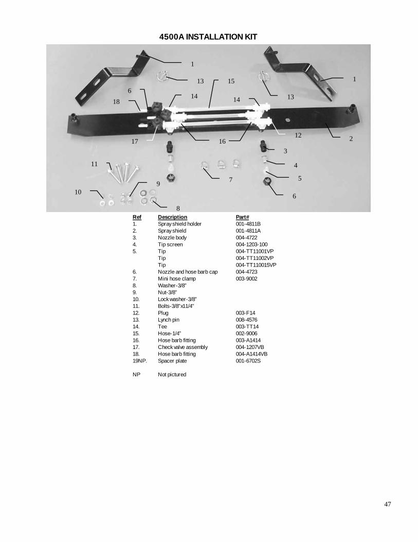
47
Ref Description Part# 1. Spray shield holder 001-4811B 2. Spray shield 001-4811A 3. Nozzle body 004-4722 4. Tip screen 004-1203-100 5. Tip 004-TT11001VP Tip 004-TT11002VP Tip 004-TT110015VP 6. Nozzle and hose barb cap 004-4723 7. Mini hose clamp 003-9002 8. Washer-3/8” 9. Nut-3/8” 10. Lock washer-3/8” 11. Bolts-3/8”x11/4” 12. Plug 003-F14 13. Lynch pin 008-4576 14. Tee 003-TT14 15. Hose-1/4” 002-9006 16. Hose barb fitting 003-A1414 17. Check valve assembly 004-1207VB 18. Hose barb fitting 004-A1414VB 19NP. Spacer plate 001-6702S
NP Not pictured
4500A INSTALLATION KIT
1
2
3
4
5
6
7
8
9 10
11
13
12
14 14
15
16 17
18
1
13 6
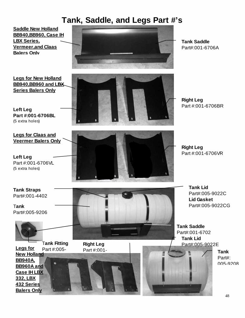
48
Tank, Saddle, and Legs Part #’s
Tank Saddle Part#:001-6706A
Right Leg Part #:001-6706BR
Tank Lid Part#:005-9022C Lid Gasket Part#:005-9022CG
Tank Straps Part#:001-4402
Tank Part#:005-9206
Tank Saddle Part#:001-6702
Saddle New Holland BB940,BB960, Case IH LBX Series, Vermeer,and Claas Balers Only
Right Leg Part #:001-6706VR
Legs for New Holland BB940,BB960 and LBX Series Balers Only
Legs for Claas and Veermer Balers Only
Left Leg Part #:001-6706VL (5 extra holes)
Left Leg Part #:001-6706BL (5 extra holes)
Tank Fitting Part #:005- Tank
Part#: 005-9208
Legs for New Holland BB940A, BB960A and Case IH LBX 332, LBX 432 Series Balers Only
Right Leg Part #:001-
Tank Lid Part#:005-9022E

49
Tank Strap Part#:001-4402B
Tank Saddle Part#:001-607A
Left Leg Part#:001-6707BL
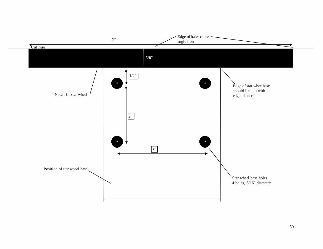
50
9”
5/8”
Star wheel base holes 4 holes, 5/16” diameter
3”
1/2”
2”
Notch for star wheel
Position of star wheel base
Edge of star wheelbase should line up with edge of notch
Edge of baler chute angle iron
Cut here angle iron

51
WARRANTY AND LIABILITY AGREEMENT
Harvest Tec, Inc. will repair or replace components that are found to be defective within 12 months from the date of purchase. Under no circumstances does this warranty cover any components which in the opinion of Harvest Tec, Inc. have been subjected to negligent use, misuse, alteration, accident, or if repairs have been made with parts other than those manufactured and obtainable from Harvest Tec, Inc. Our obligation under this warranty is limited to repairing or replacing free of charge to the original purchase any part that in our judgment shows evidence of defective or improper workmanship, provided the part is returned to Harvest Tec, Inc. within 30 days of the failure. Parts must be returned through the selling dealer and distributor, transportation charges prepaid. It will be the purchaser’s responsibility to provide proof of such purchase. This warranty shall not be interpreted to render Harvest Tec, Inc. liable for injury or damages of any kind, direct, consequential, or contingent, to persons or property. Furthermore, this warranty does not extend to loss of crop, losses caused by delays or any expense prospective profits or for any other reason. Harvest Tec, Inc. shall not be liable for any recovery greater in amount than the cost or repair of defects in workmanship. There are no warranties, either expressed or implied, of merchantability or fitness for particular purpose intended or fitness for any other reason. This warranty cannot guarantee that existing conditions beyond the control of Harvest Tec, Inc. will not affect our ability to obtain materials or manufacture necessary replacement parts. Harvest Tec, Inc. reserves the right to make design changes, improve design, or change specifications, at any time without any contingent obligation to purchasers of machines and parts previously sold.