Embed Size (px)
Citation preview
Hart Transmitter Calibration Fluke Corporation 1
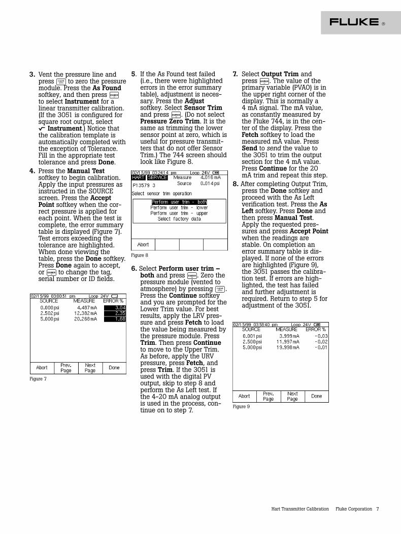
Application Note
HART® TransmitterCalibration
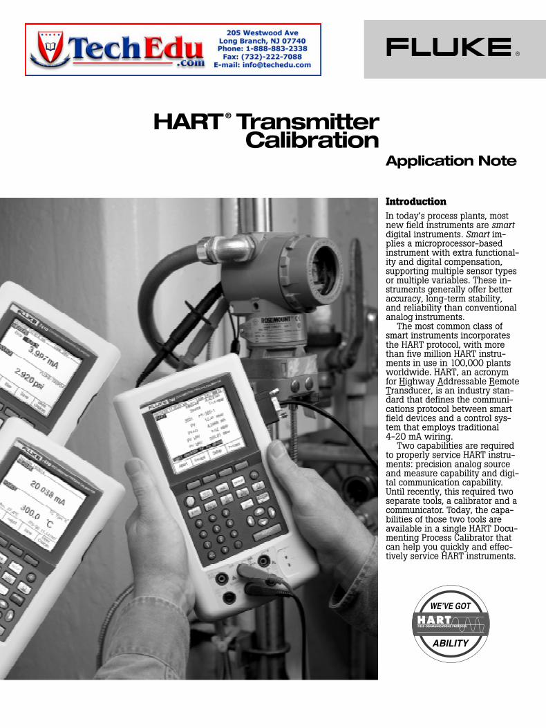
IntroductionIn today’s process plants, mostnew field instruments are smartdigital instruments. Smart im-plies a microprocessor-basedinstrument with extra functional-ity and digital compensation,supporting multiple sensor typesor multiple variables. These in-struments generally offer betteraccuracy, long-term stability,and reliability than conventionalanalog instruments.
The most common class ofsmart instruments incorporatesthe HART protocol, with morethan five million HART instru-ments in use in 100,000 plantsworldwide. HART, an acronymfor Highway Addressable RemoteTransducer, is an industry stan-dard that defines the communi-cations protocol between smartfield devices and a control sys-tem that employs traditional4-20 mA wiring.
Two capabilities are requiredto properly service HART instru-ments: precision analog sourceand measure capability and digi-tal communication capability.Until recently, this required twoseparate tools, a calibrator and acommunicator. Today, the capa-bilities of those two tools areavailable in a single HART Docu-menting Process Calibrator thatcan help you quickly and effec-tively service HART instruments.
2 Fluke Corporation Hart Transmitter Calibration
HART calibrationis required!A common misconception isthat the accuracy and stabilityof HART instruments eliminatethe need for calibration.Another misconception is thatcalibration can be accomplishedby re-ranging field instrumentsusing only a HART communica-tor. Still another misconceptionis that the control system canremotely calibrate smart instru-ments. These are not true. Allinstruments drift. Re-rangingwith just a communicator is notcalibration. A precision calibra-tor or standard is required.Regular performance verifica-tion with a calibrator traceableto national standards is neces-sary due to:1. Shifts in performance of
electronic instruments overtime, due to exposure of theelectronics and the primarysensing element to tempera-ture, humidity, pollutants,vibration, and other fieldenvironmental factors.
2. Regulations governing occu-pational safety, consumersafety, and environmentalprotection.
3. Quality programs such asISO 9000 standards for allinstruments that impactproduct quality.
4. Commercial requirementssuch as weights, measures,and custody transfer.
Regular calibration is also pru-dent since performance checkswill often uncover problems notdirectly caused by the instru-mentation, such as solidified orcongealed pressure lines, in-stallation of an incorrect ther-mocouple type, or other errorsand faults.
A calibration procedure con-sists of a verification (As Found)test, adjustment to within ac-ceptable tolerance if necessary,and a final verification (As Left)test if an adjustment has beenmade. Data from the calibrationare collected and used to com-plete a report of calibration,documenting instrument per-formance over time.
All instruments, even HARTinstruments, must be calibratedon a regular, preventive main-tenance schedule. The calibra-tion interval should be set shortenough to insure that an in-strument never drifts out oftolerance, yet long enough toavoid unnecessary calibrations.Alternatively, the interval maybe determined by critical pro-cess requirements, e.g., calibra-tion before each batch.
How are HARTinstruments properlycalibrated?To calibrate a HART instrumentconsistent with its application, itis very helpful to understand thefunctional structure of a typicalHART transmitter. The article inAppendix A, by Kenneth L.Holladay of Southwest ResearchInstitute, describes a typicalHART instrument and definesboth proper and improper cali-bration practices. Originallypublished in Intech, May 1996, itis reprinted with permission ofthe author.Note: If you are unfamiliar with HARTcalibration or need a review, this is anexcellent point to stop and read the articlein Appendix A. It covers the basics of HARTinstrumentation and addresses issues criticalto instrument maintenance.
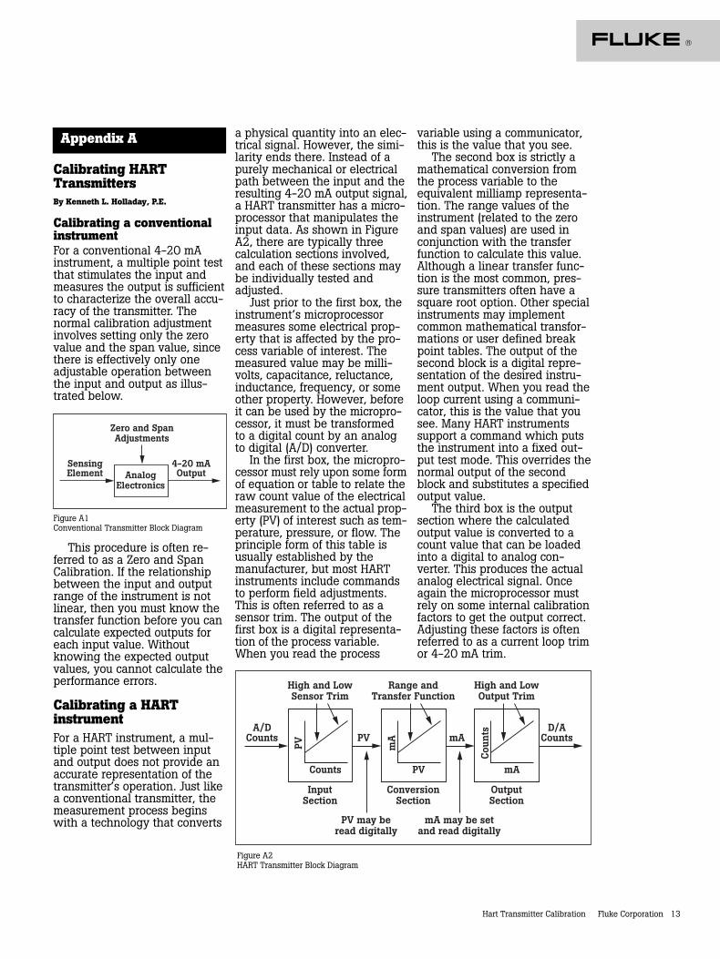
HART instruments consist ofthree distinct sections (seeFigure 1). Proper HART calibra-tion may involve either or bothsensor trim and output trim.Adjusting range values (LRV andURV) without a calibrator is notcalibration. Performing an outputtrim while ignoring the inputsection is not proper calibration.Adjusting range values with acalibrator may be a practicalcalibration alternative for instru-ments operated in 4-20 mAanalog mode, provided that thePV and PVAO are not used forprocess control.
Sensor
Sensor Trim LRV/URV Adjust Output Trim
PV PVAO 4-20 mAInputSection
ConversionSection
OutputSection
AnalogInput (digital
input)(digital
4-20 mA)
Analog mA Output
Figure 1
Hart Transmitter Calibration Fluke Corporation 3
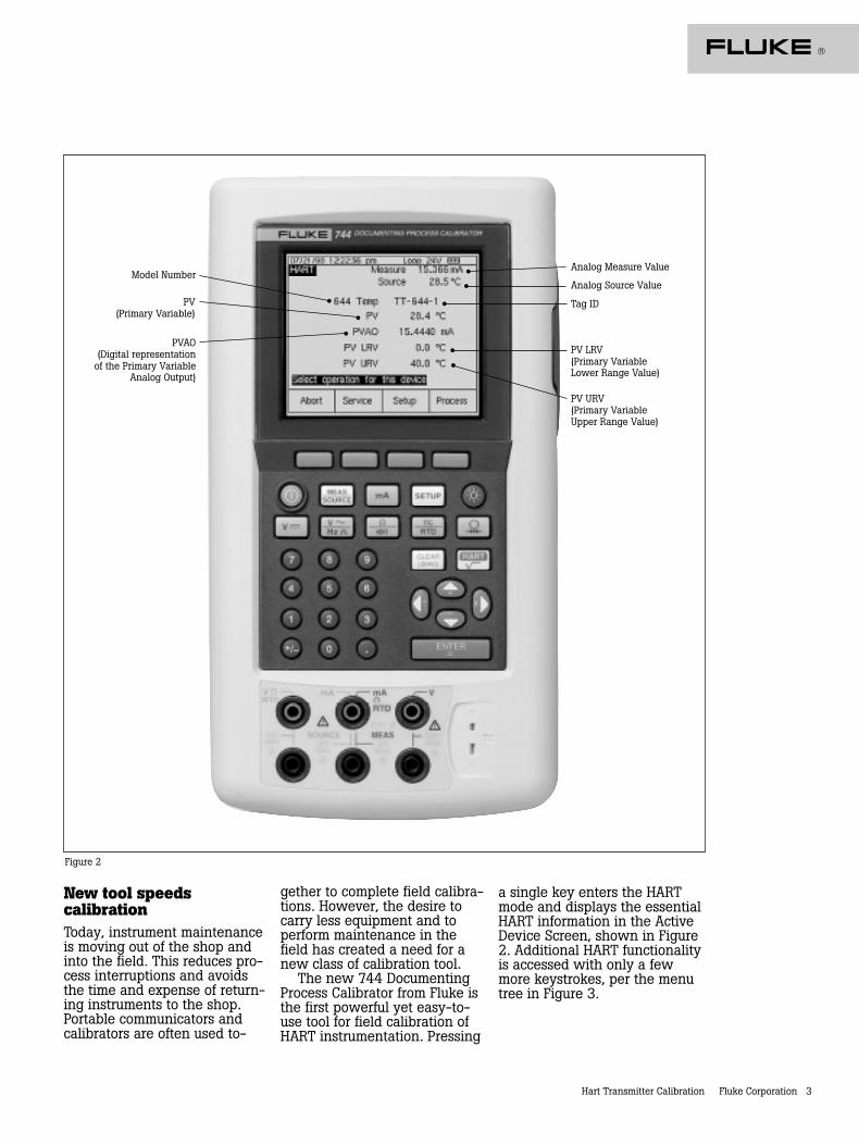
Figure 2
Model Number
PV(Primary Variable)
PVAO(Digital representation
of the Primary VariableAnalog Output)
Analog Measure Value
Analog Source Value
Tag ID
PV LRV(Primary VariableLower Range Value)
PV URV(Primary VariableUpper Range Value)
New tool speedscalibrationToday, instrument maintenanceis moving out of the shop andinto the field. This reduces pro-cess interruptions and avoidsthe time and expense of return-ing instruments to the shop.Portable communicators andcalibrators are often used to-
gether to complete field calibra-tions. However, the desire tocarry less equipment and toperform maintenance in thefield has created a need for anew class of calibration tool.
The new 744 DocumentingProcess Calibrator from Fluke isthe first powerful yet easy-to-use tool for field calibration ofHART instrumentation. Pressing
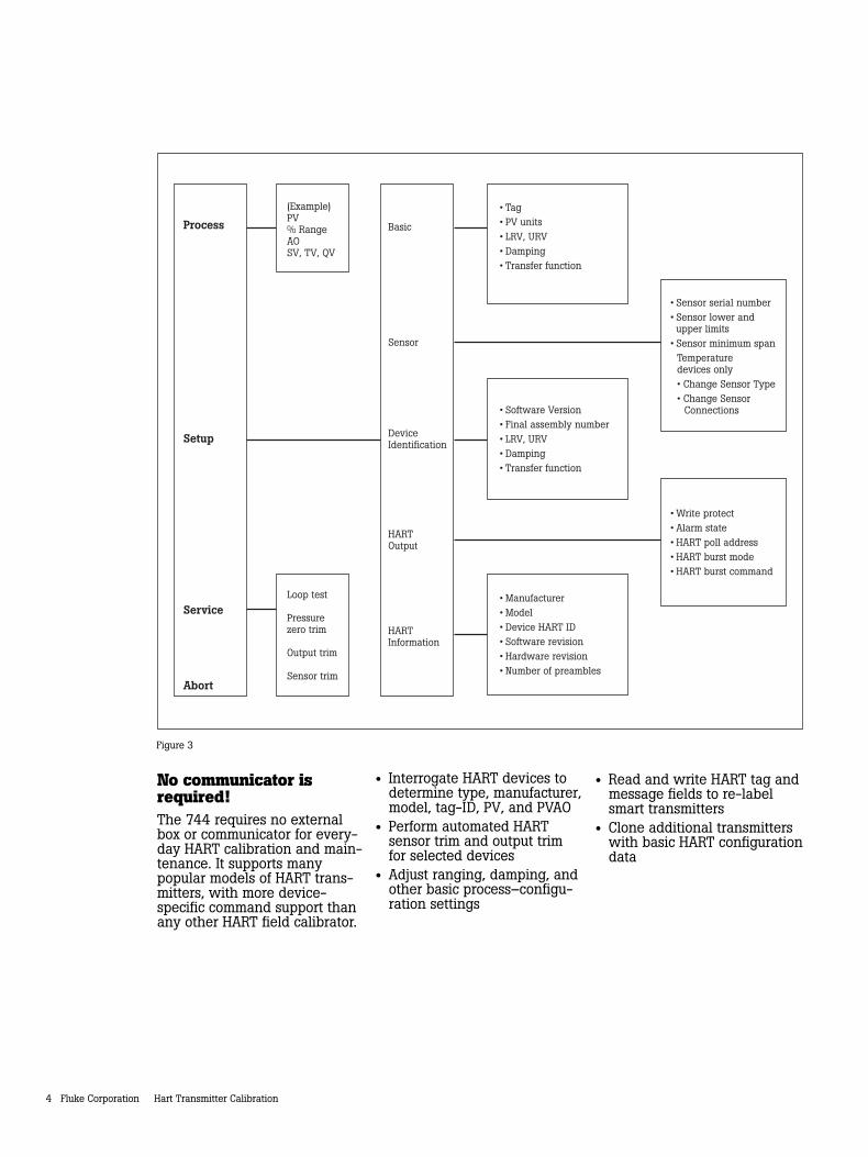
a single key enters the HARTmode and displays the essentialHART information in the ActiveDevice Screen, shown in Figure2. Additional HART functionalityis accessed with only a fewmore keystrokes, per the menutree in Figure 3.
4 Fluke Corporation Hart Transmitter Calibration
No communicator isrequired!The 744 requires no externalbox or communicator for every-day HART calibration and main-tenance. It supports manypopular models of HART trans-mitters, with more device-specific command support thanany other HART field calibrator.
• Interrogate HART devices todetermine type, manufacturer,model, tag-ID, PV, and PVAO
• Perform automated HARTsensor trim and output trimfor selected devices
• Adjust ranging, damping, andother basic process–configu-ration settings
• Read and write HART tag andmessage fields to re-labelsmart transmitters
• Clone additional transmitterswith basic HART configurationdata
Process
Setup
Service
Abort
DeviceIdentification
HARTOutput
HARTInformation
Basic
Sensor
(Example)PV% RangeAOSV, TV, QV
Loop test
Pressurezero trim
Output trim
Sensor trim
• Tag• PV units• LRV, URV• Damping• Transfer function
• Sensor serial number• Sensor lower and upper limits
• Sensor minimum spanTemperature devices only• Change Sensor Type• Change Sensor
Connections
• Write protect• Alarm state• HART poll address• HART burst mode• HART burst command
• Software Version• Final assembly number• LRV, URV• Damping• Transfer function
• Manufacturer• Model• Device HART ID• Software revision• Hardware revision• Number of preambles
Figure 3
Hart Transmitter Calibration Fluke Corporation 5
Is there still a role for thecommunicator?Commissioning a HART instru-ment or modifying HART vari-ables not supported by the 744requires the use of a communi-cator. The 744 is designed toperform the vast majority ofday-to-day operations you nor-mally perform with a separatecommunicator. The HART capa-bility of the 744 is comparableto that of the model 275 HARTcommunicator, with the excep-tion of the DD interpreter. Whilethe DD interpreter enables the275 communicator to read com-mand set libraries from anyHART supplier, it offers capabili-ties far beyond those generallyrequired for daily HART instru-ment maintenance.
HART calibrationapplicationsThe following examples demon-strate how the 744 makes HARTcalibration an efficient opera-tion. The 744 enables easyhookup using its HART cable,fast access to the most impor-tant HART data, automaticbranching to appropriate adjust-ment choices, automaticcompletion of test templates,and automatic fetching andsending of analog readingsduring trim.
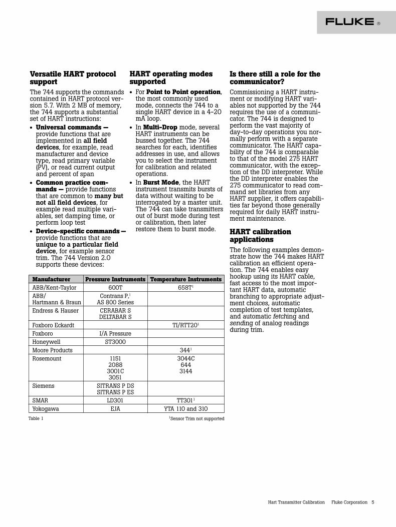
Versatile HART protocolsupportThe 744 supports the commandscontained in HART protocol ver-sion 5.7. With 2 MB of memory,the 744 supports a substantialset of HART instructions:• Universal commands —
provide functions that areimplemented in all fielddevices, for example, readmanufacturer and devicetype, read primary variable(PV), or read current outputand percent of span
• Common practice com-mands — provide functionsthat are common to many butnot all field devices, forexample read multiple vari-ables, set damping time, orperform loop test
• Device-specific commands —provide functions that areunique to a particular fielddevice, for example sensortrim. The 744 Version 2.0supports these devices:
Manufacturer Pressure Instruments Temperature InstrumentsABB/Kent-Taylor 600T 658T1
ABB/ Contrans P,1Hartmann & Braun AS 800 SeriesEndress & Hauser CERABAR S
DELTABAR SFoxboro Eckardt TI/RTT201
Foxboro I/A PressureHoneywell ST3000Moore Products 3441
Rosemount 1151 3044C2088 6443001C 31443051
Siemens SITRANS P DSSITRANS P ES
SMAR LD301 TT3011
Yokogawa EJA YTA 110 and 3101Sensor Trim not supported
HART operating modessupported• For Point to Point operation,
the most commonly usedmode, connects the 744 to asingle HART device in a 4-20mA loop.
• In Multi-Drop mode, severalHART instruments can bebussed together. The 744searches for each, identifiesaddresses in use, and allowsyou to select the instrumentfor calibration and relatedoperations.
• In Burst Mode, the HARTinstrument transmits bursts ofdata without waiting to beinterrogated by a master unit.The 744 can take transmittersout of burst mode during testor calibration, then laterrestore them to burst mode.
Table 1
6 Fluke Corporation Hart Transmitter Calibration
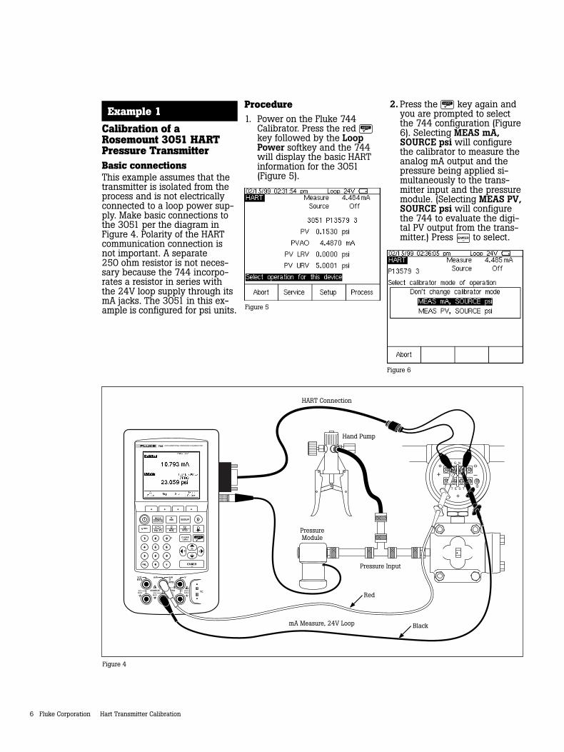
Example 1
Calibration of aRosemount 3051 HARTPressure TransmitterBasic connectionsThis example assumes that thetransmitter is isolated from theprocess and is not electricallyconnected to a loop power sup-ply. Make basic connections tothe 3051 per the diagram inFigure 4. Polarity of the HARTcommunication connection isnot important. A separate250 ohm resistor is not neces-sary because the 744 incorpo-rates a resistor in series withthe 24V loop supply through itsmA jacks. The 3051 in this ex-ample is configured for psi units.
Figure 4
Figure 5
Figure 6
TC
mA mA VVRTD
RTD
SOURCE 300VMAX30V
MAX30VMAX
30VMAX
MEASCAT
MEASSOURCE SETUPmA
V VHz
TCRTD
7 8 9
4 5 6
1 2 3
0 .
Hand Pump
HART Connection
S I G N A L
T E S T
+ –
PressureModule
Pressure Input
mA Measure, 24V Loop
Red
Black
ENTER
CLEAR(ZERO)
DOCUMENTING PROCESS CALIBRATOR744
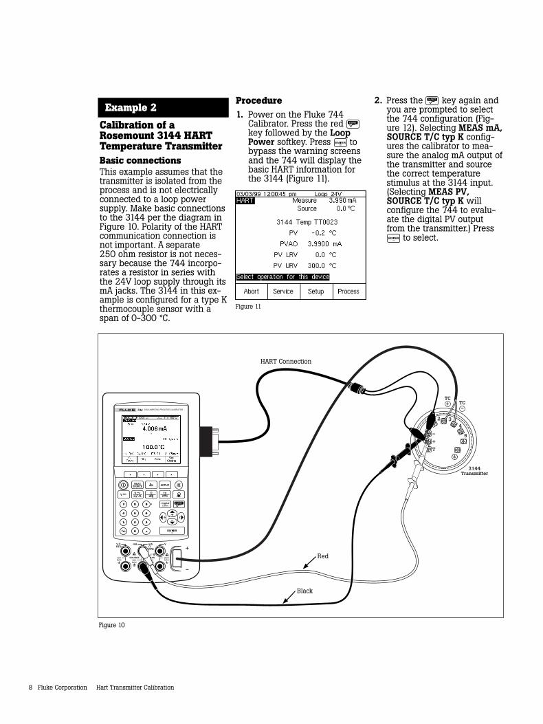
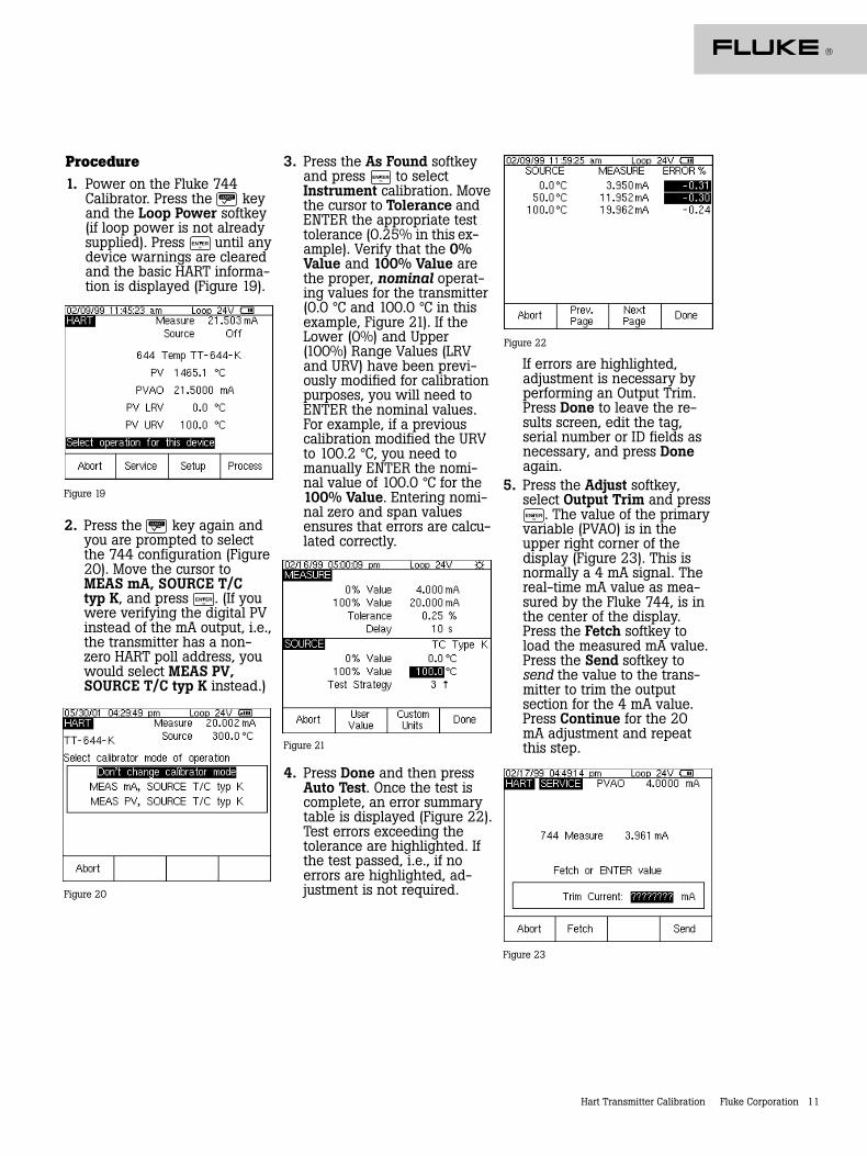
Procedure1. Power on the Fluke 744
Calibrator. Press the red key followed by the LoopPower softkey and the 744will display the basic HARTinformation for the 3051(Figure 5).
2. Press the key again andyou are prompted to selectthe 744 configuration (Figure6). Selecting MEAS mA,SOURCE psi will configurethe calibrator to measure theanalog mA output and thepressure being applied si-multaneously to the trans-mitter input and the pressuremodule. (Selecting MEAS PV,SOURCE psi will configurethe 744 to evaluate the digi-tal PV output from the trans-mitter.) Press ENTER to select.
Hart Transmitter Calibration Fluke Corporation 7
3. Vent the pressure line andpress CLEAR
(ZERO) to zero the pressuremodule. Press the As Foundsoftkey, and then press ENTER
to select Instrument for alinear transmitter calibration.(If the 3051 is configured forsquare root output, select
Instrument.) Notice thatthe calibration template isautomatically completed withthe exception of Tolerance.Fill in the appropriate testtolerance and press Done.
4. Press the Manual Testsoftkey to begin calibration.Apply the input pressures asinstructed in the SOURCEscreen. Press the AcceptPoint softkey when the cor-rect pressure is applied foreach point. When the test iscomplete, the error summarytable is displayed (Figure 7).Test errors exceeding thetolerance are highlighted.When done viewing thetable, press the Done softkey.Press Done again to accept,or ENTER to change the tag,serial number or ID fields.
Figure 7
Figure 8
5. If the As Found test failed(i.e., there were highlightederrors in the error summarytable), adjustment is neces-sary. Press the Adjustsoftkey. Select Sensor Trimand press ENTER . (Do not selectPressure Zero Trim. It is thesame as trimming the lowersensor point at zero, which isuseful for pressure transmit-ters that do not offer SensorTrim.) The 744 screen shouldlook like Figure 8.
Figure 9
7. Select Output Trim andpress ENTER . The value of theprimary variable (PVAO) is inthe upper right corner of thedisplay. This is normally a4 mA signal. The mA value,as constantly measured bythe Fluke 744, is in the cen-ter of the display. Press theFetch softkey to load themeasured mA value. PressSend to send the value tothe 3051 to trim the outputsection for the 4 mA value.Press Continue for the 20mA trim and repeat this step.
8. After completing Output Trim,press the Done softkey andproceed with the As Leftverification test. Press the AsLeft softkey. Press Done andthen press Manual Test.Apply the requested pres-sures and press Accept Pointwhen the readings arestable. On completion anerror summary table is dis-played. If none of the errorsare highlighted (Figure 9),the 3051 passes the calibra-tion test. If errors are high-lighted, the test has failedand further adjustment isrequired. Return to step 5 foradjustment of the 3051.
6. Select Perform user trim –both and press ENTER . Zero thepressure module (vented toatmosphere) by pressing CLEAR
(ZERO) .Press the Continue softkeyand you are prompted for theLower Trim value. For bestresults, apply the LRV pres-sure and press Fetch to loadthe value being measured bythe pressure module. PressTrim. Then press Continueto move to the Upper Trim.As before, apply the URVpressure, press Fetch, andpress Trim. If the 3051 isused with the digital PVoutput, skip to step 8 andperform the As Left test. Ifthe 4-20 mA analog outputis used in the process, con-tinue on to step 7.
8 Fluke Corporation Hart Transmitter Calibration
Example 2
Calibration of aRosemount 3144 HARTTemperature TransmitterBasic connectionsThis example assumes that thetransmitter is isolated from theprocess and is not electricallyconnected to a loop powersupply. Make basic connectionsto the 3144 per the diagram inFigure 10. Polarity of the HARTcommunication connection isnot important. A separate250 ohm resistor is not neces-sary because the 744 incorpo-rates a resistor in series withthe 24V loop supply through itsmA jacks. The 3144 in this ex-ample is configured for a type Kthermocouple sensor with aspan of 0-300 °C.
12 3
4
5
T
+
–
TC
mA mA VVRTD
RTD
SOURCE 300VMAX30V
MAX30VMAX
30VMAX
MEASCAT
MEASSOURCE SETUPmA
V VHz
TCRTD
7 8 9
4 5 6
1 2 3
0 .
HART Connection
Red
Black
ENTER
CLEAR(ZERO)
DOCUMENTING PROCESS CALIBRATOR744
+
–
3144Transmitter
TC+ TC
–
Figure 10
Procedure1. Power on the Fluke 744
Calibrator. Press the red key followed by the LoopPower softkey. Press ENTER tobypass the warning screensand the 744 will display thebasic HART information forthe 3144 (Figure 11).
Figure 11
2. Press the key again andyou are prompted to selectthe 744 configuration (Fig-ure 12). Selecting MEAS mA,SOURCE T/C typ K config-ures the calibrator to mea-sure the analog mA output ofthe transmitter and sourcethe correct temperaturestimulus at the 3144 input.(Selecting MEAS PV,SOURCE T/C typ K willconfigure the 744 to evalu-ate the digital PV outputfrom the transmitter.) PressENTER to select.
Hart Transmitter Calibration Fluke Corporation 9
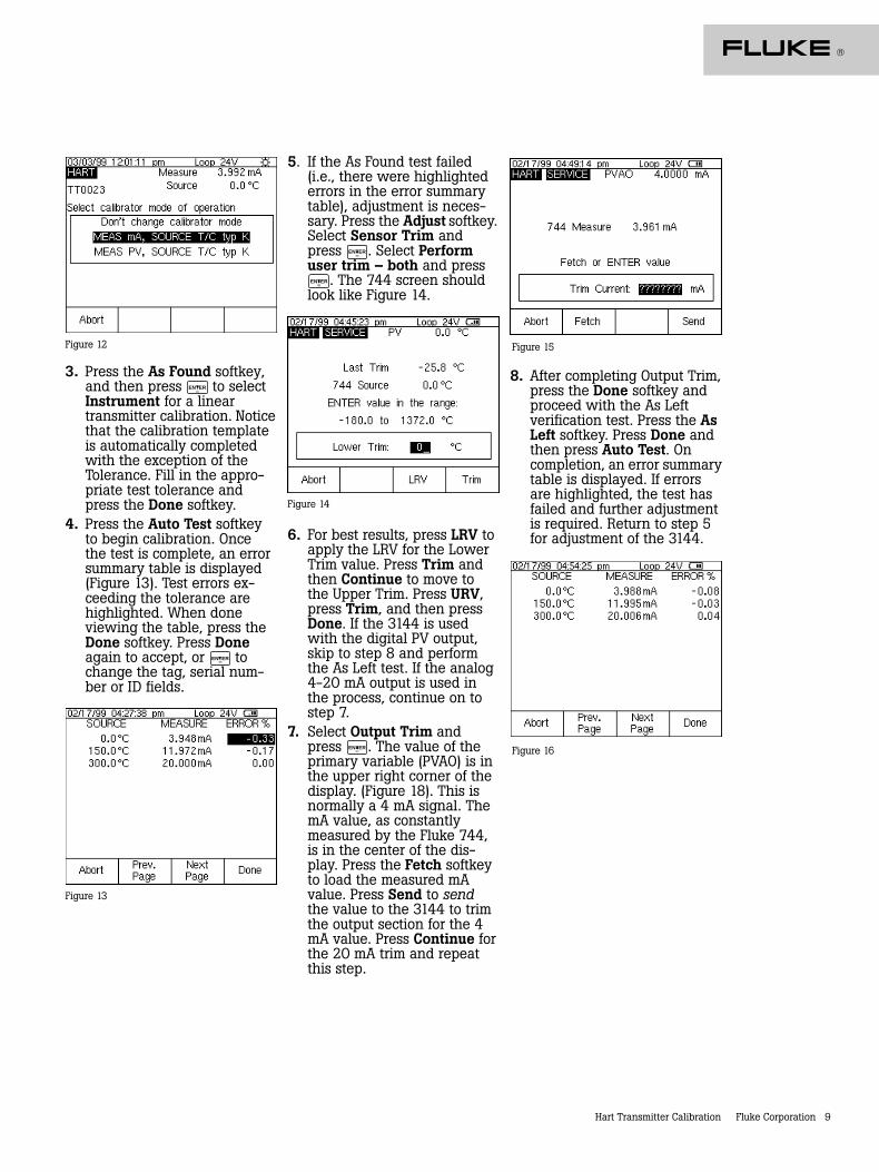
3. Press the As Found softkey,and then press ENTER to selectInstrument for a lineartransmitter calibration. Noticethat the calibration templateis automatically completedwith the exception of theTolerance. Fill in the appro-priate test tolerance andpress the Done softkey.
4. Press the Auto Test softkeyto begin calibration. Oncethe test is complete, an errorsummary table is displayed(Figure 13). Test errors ex-ceeding the tolerance arehighlighted. When doneviewing the table, press theDone softkey. Press Doneagain to accept, or ENTER tochange the tag, serial num-ber or ID fields.
Figure 12
Figure 13
5. If the As Found test failed(i.e., there were highlightederrors in the error summarytable), adjustment is neces-sary. Press the Adjust softkey.Select Sensor Trim andpress ENTER . Select Performuser trim – both and pressENTER . The 744 screen shouldlook like Figure 14.
6. For best results, press LRV toapply the LRV for the LowerTrim value. Press Trim andthen Continue to move tothe Upper Trim. Press URV,press Trim, and then pressDone. If the 3144 is usedwith the digital PV output,skip to step 8 and performthe As Left test. If the analog4-20 mA output is used inthe process, continue on tostep 7.
7. Select Output Trim andpress ENTER . The value of theprimary variable (PVAO) is inthe upper right corner of thedisplay. (Figure 18). This isnormally a 4 mA signal. ThemA value, as constantlymeasured by the Fluke 744,is in the center of the dis-play. Press the Fetch softkeyto load the measured mAvalue. Press Send to sendthe value to the 3144 to trimthe output section for the 4mA value. Press Continue forthe 20 mA trim and repeatthis step.
Figure 14
8. After completing Output Trim,press the Done softkey andproceed with the As Leftverification test. Press the AsLeft softkey. Press Done andthen press Auto Test. Oncompletion, an error summarytable is displayed. If errorsare highlighted, the test hasfailed and further adjustmentis required. Return to step 5for adjustment of the 3144.
Figure 15
Figure 16
10 Fluke Corporation Hart Transmitter Calibration
Example 3
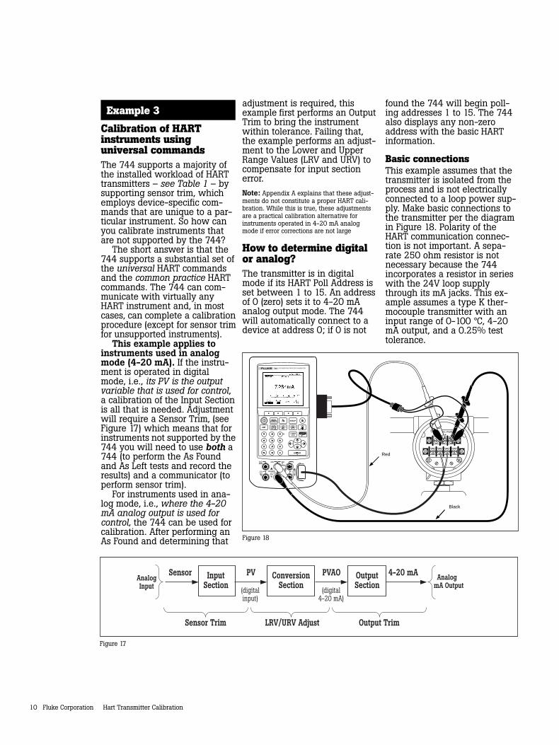
Calibration of HARTinstruments usinguniversal commandsThe 744 supports a majority ofthe installed workload of HARTtransmitters – see Table 1 – bysupporting sensor trim, whichemploys device-specific com-mands that are unique to a par-ticular instrument. So how canyou calibrate instruments thatare not supported by the 744?
The short answer is that the744 supports a substantial set ofthe universal HART commandsand the common practice HARTcommands. The 744 can com-municate with virtually anyHART instrument and, in mostcases, can complete a calibrationprocedure (except for sensor trimfor unsupported instruments).
This example applies toinstruments used in analogmode (4-20 mA). If the instru-ment is operated in digitalmode, i.e., its PV is the outputvariable that is used for control,a calibration of the Input Sectionis all that is needed. Adjustmentwill require a Sensor Trim, (seeFigure 17) which means that forinstruments not supported by the744 you will need to use both a744 (to perform the As Foundand As Left tests and record theresults) and a communicator (toperform sensor trim).
For instruments used in ana-log mode, i.e., where the 4-20mA analog output is used forcontrol, the 744 can be used forcalibration. After performing anAs Found and determining that
Sensor
Sensor Trim LRV/URV Adjust Output Trim
PV PVAO 4-20 mAInputSection
ConversionSection
OutputSection
AnalogInput (digital
input)(digital
4-20 mA)
Analog mA Output
Figure 17
adjustment is required, thisexample first performs an OutputTrim to bring the instrumentwithin tolerance. Failing that,the example performs an adjust-ment to the Lower and UpperRange Values (LRV and URV) tocompensate for input sectionerror.Note: Appendix A explains that these adjust-ments do not constitute a proper HART cali-bration. While this is true, these adjustmentsare a practical calibration alternative forinstruments operated in 4-20 mA analogmode if error corrections are not large
How to determine digitalor analog?The transmitter is in digitalmode if its HART Poll Address isset between 1 to 15. An addressof 0 (zero) sets it to 4-20 mAanalog output mode. The 744will automatically connect to adevice at address 0; if 0 is not
found the 744 will begin poll-ing addresses 1 to 15. The 744also displays any non-zeroaddress with the basic HARTinformation.
Basic connectionsThis example assumes that thetransmitter is isolated from theprocess and is not electricallyconnected to a loop power sup-ply. Make basic connections tothe transmitter per the diagramin Figure 18. Polarity of theHART communication connec-tion is not important. A sepa-rate 250 ohm resistor is notnecessary because the 744incorporates a resistor in serieswith the 24V loop supplythrough its mA jacks. This ex-ample assumes a type K ther-mocouple transmitter with aninput range of 0-100 °C, 4-20mA output, and a 0.25% testtolerance.
TC
mA mA VVRTD
RTD
SOURCE 300VMAX30V
MAX30VMAX
30VMAX
MEASCAT
MEASSOURCE SETUPmA
V VHz
TCRTD
7 8 9
4 5 6
1 2 3
0 . Red
TEST DC PWR+ –+–
Black
ENTER
CLEAR(ZERO)
DOCUMENTING PROCESS CALIBRATOR744
Figure 18
Hart Transmitter Calibration Fluke Corporation 11
Procedure1. Power on the Fluke 744
Calibrator. Press the keyand the Loop Power softkey(if loop power is not alreadysupplied). Press ENTER until anydevice warnings are clearedand the basic HART informa-tion is displayed (Figure 19).
2. Press the key again andyou are prompted to selectthe 744 configuration (Figure20). Move the cursor toMEAS mA, SOURCE T/Ctyp K, and press ENTER . (If youwere verifying the digital PVinstead of the mA output, i.e.,the transmitter has a non-zero HART poll address, youwould select MEAS PV,SOURCE T/C typ K instead.)
Figure 19
Figure 20
3. Press the As Found softkeyand press ENTER to selectInstrument calibration. Movethe cursor to Tolerance andENTER the appropriate testtolerance (0.25% in this ex-ample). Verify that the 0%Value and 100% Value arethe proper, nominal operat-ing values for the transmitter(0.0 °C and 100.0 °C in thisexample, Figure 21). If theLower (0%) and Upper(100%) Range Values (LRVand URV) have been previ-ously modified for calibrationpurposes, you will need toENTER the nominal values.For example, if a previouscalibration modified the URVto 100.2 °C, you need tomanually ENTER the nomi-nal value of 100.0 °C for the100% Value. Entering nomi-nal zero and span valuesensures that errors are calcu-lated correctly.
Figure 21
4. Press Done and then pressAuto Test. Once the test iscomplete, an error summarytable is displayed (Figure 22).Test errors exceeding thetolerance are highlighted. Ifthe test passed, i.e., if noerrors are highlighted, ad-justment is not required.
If errors are highlighted,adjustment is necessary byperforming an Output Trim.Press Done to leave the re-sults screen, edit the tag,serial number or ID fields asnecessary, and press Doneagain.
5. Press the Adjust softkey,select Output Trim and pressENTER . The value of the primaryvariable (PVAO) is in theupper right corner of thedisplay (Figure 23). This isnormally a 4 mA signal. Thereal-time mA value as mea-sured by the Fluke 744, is inthe center of the display.Press the Fetch softkey toload the measured mA value.Press the Send softkey tosend the value to the trans-mitter to trim the outputsection for the 4 mA value.Press Continue for the 20mA adjustment and repeatthis step.
Figure 22
Figure 23
12 Fluke Corporation Hart Transmitter Calibration
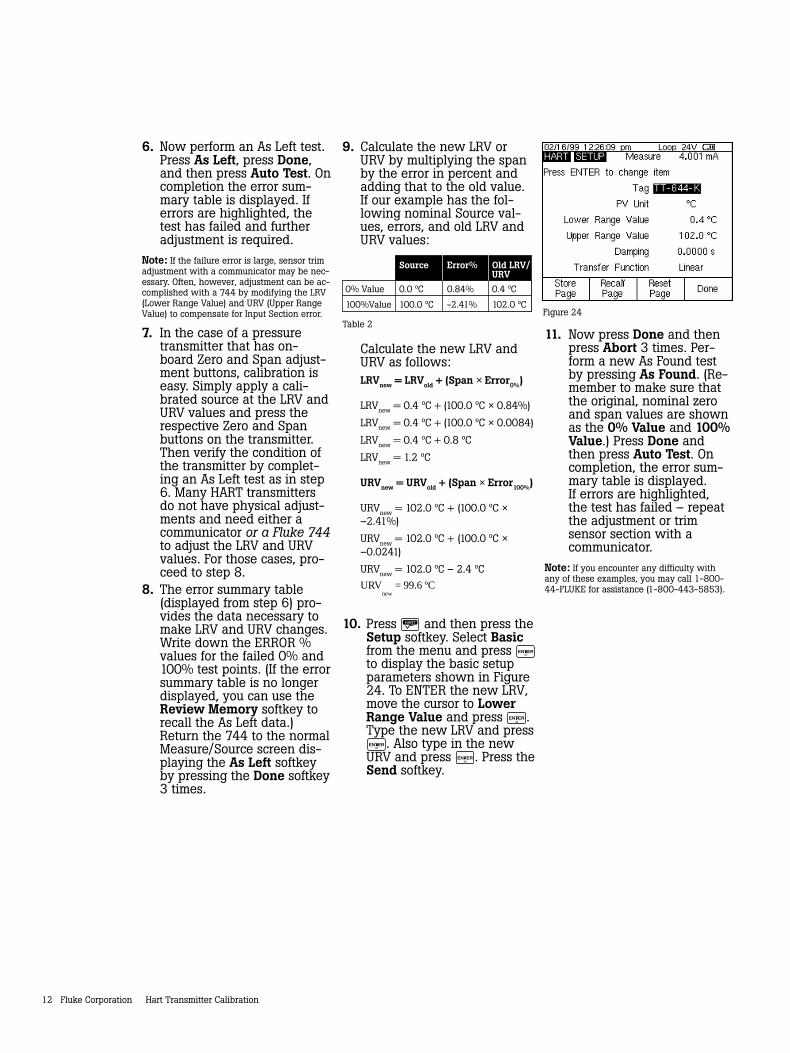
6. Now perform an As Left test.Press As Left, press Done,and then press Auto Test. Oncompletion the error sum-mary table is displayed. Iferrors are highlighted, thetest has failed and furtheradjustment is required.
Note: If the failure error is large, sensor trimadjustment with a communicator may be nec-essary. Often, however, adjustment can be ac-complished with a 744 by modifying the LRV(Lower Range Value) and URV (Upper RangeValue) to compensate for Input Section error.
7. In the case of a pressuretransmitter that has on-board Zero and Span adjust-ment buttons, calibration iseasy. Simply apply a cali-brated source at the LRV andURV values and press therespective Zero and Spanbuttons on the transmitter.Then verify the condition ofthe transmitter by complet-ing an As Left test as in step6. Many HART transmittersdo not have physical adjust-ments and need either acommunicator or a Fluke 744to adjust the LRV and URVvalues. For those cases, pro-ceed to step 8.
8. The error summary table(displayed from step 6) pro-vides the data necessary tomake LRV and URV changes.Write down the ERROR %values for the failed 0% and100% test points. (If the errorsummary table is no longerdisplayed, you can use theReview Memory softkey torecall the As Left data.)Return the 744 to the normalMeasure/Source screen dis-playing the As Left softkeyby pressing the Done softkey3 times.
9. Calculate the new LRV orURV by multiplying the spanby the error in percent andadding that to the old value.If our example has the fol-lowing nominal Source val-ues, errors, and old LRV andURV values:
Source Error% Old LRV/URV
0% Value 0.0 ºC 0.84% 0.4 ºC
100%Value 100.0 ºC -2.41% 102.0 ºC
Calculate the new LRV andURV as follows:LRVnew = LRVold + (Span × Error0%)
LRVnew = 0.4 ºC + (100.0 ºC × 0.84%)
LRVnew = 0.4 ºC + (100.0 ºC × 0.0084)
LRVnew = 0.4 ºC + 0.8 ºC
LRVnew = 1.2 ºC
URVnew = URVold + (Span × Error100%)
URVnew = 102.0 ºC + (100.0 ºC ×–2.41%)
URVnew = 102.0 ºC + (100.0 ºC ×–0.0241)
URVnew = 102.0 ºC – 2.4 ºC
URVnew
= 99.6 ºC
10. Press and then press theSetup softkey. Select Basicfrom the menu and press ENTER
to display the basic setupparameters shown in Figure24. To ENTER the new LRV,move the cursor to LowerRange Value and press ENTER .Type the new LRV and pressENTER . Also type in the newURV and press ENTER . Press theSend softkey.
Table 211. Now press Done and then
press Abort 3 times. Per-form a new As Found testby pressing As Found. (Re-member to make sure thatthe original, nominal zeroand span values are shownas the 0% Value and 100%Value.) Press Done andthen press Auto Test. Oncompletion, the error sum-mary table is displayed.If errors are highlighted,the test has failed – repeatthe adjustment or trimsensor section with acommunicator.
Note: If you encounter any difficulty withany of these examples, you may call 1-800-44-FLUKE for assistance (1-800-443-5853).
Figure 24
Hart Transmitter Calibration Fluke Corporation 13
Appendix A
Calibrating HARTTransmittersBy Kenneth L. Holladay, P.E.
Calibrating a conventionalinstrumentFor a conventional 4-20 mAinstrument, a multiple point testthat stimulates the input andmeasures the output is sufficientto characterize the overall accu-racy of the transmitter. Thenormal calibration adjustmentinvolves setting only the zerovalue and the span value, sincethere is effectively only oneadjustable operation betweenthe input and output as illus-trated below.
SensingElement
4-20 mAOutputAnalog
Electronics
Zero and SpanAdjustments
Figure A1Conventional Transmitter Block Diagram
This procedure is often re-ferred to as a Zero and SpanCalibration. If the relationshipbetween the input and outputrange of the instrument is notlinear, then you must know thetransfer function before you cancalculate expected outputs foreach input value. Withoutknowing the expected outputvalues, you cannot calculate theperformance errors.
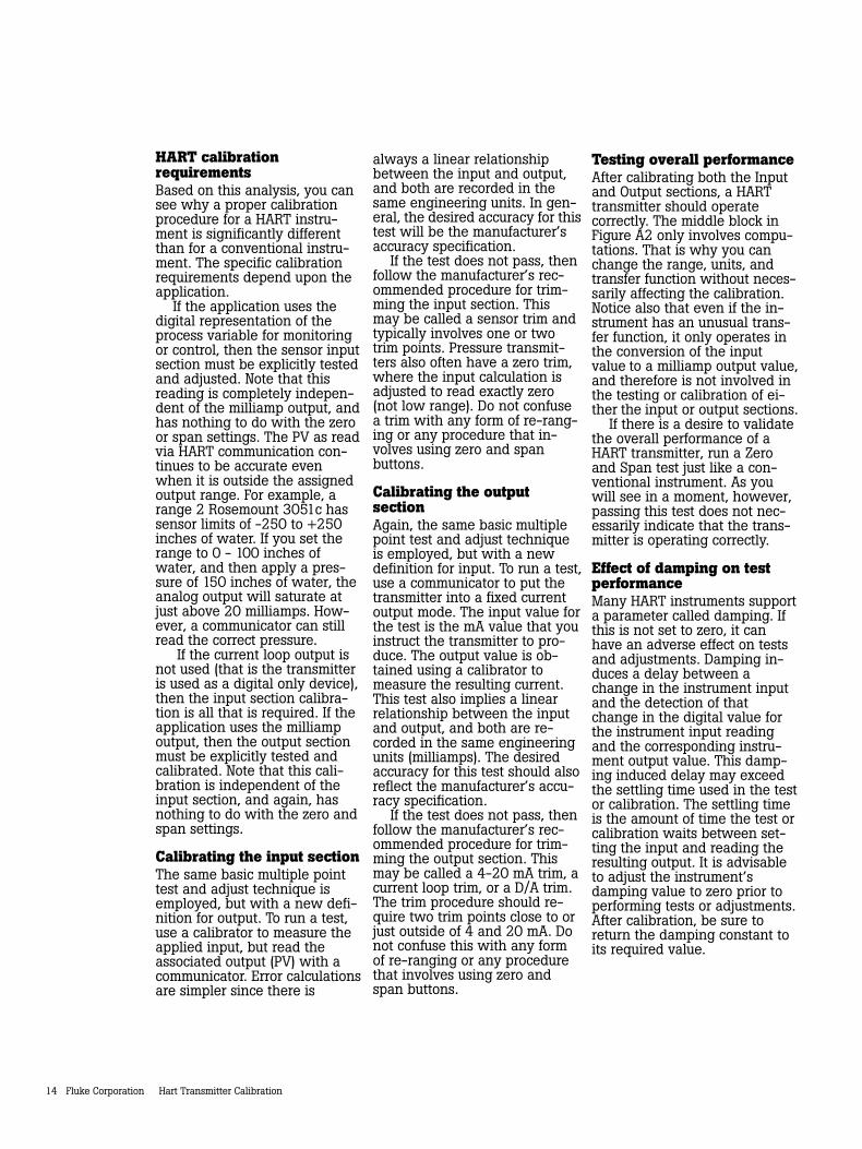
Calibrating a HARTinstrumentFor a HART instrument, a mul-tiple point test between inputand output does not provide anaccurate representation of thetransmitter’s operation. Just likea conventional transmitter, themeasurement process beginswith a technology that converts
a physical quantity into an elec-trical signal. However, the simi-larity ends there. Instead of apurely mechanical or electricalpath between the input and theresulting 4-20 mA output signal,a HART transmitter has a micro-processor that manipulates theinput data. As shown in FigureA2, there are typically threecalculation sections involved,and each of these sections maybe individually tested andadjusted.
Just prior to the first box, theinstrument’s microprocessormeasures some electrical prop-erty that is affected by the pro-cess variable of interest. Themeasured value may be milli-volts, capacitance, reluctance,inductance, frequency, or someother property. However, beforeit can be used by the micropro-cessor, it must be transformedto a digital count by an analogto digital (A/D) converter.
In the first box, the micropro-cessor must rely upon some formof equation or table to relate theraw count value of the electricalmeasurement to the actual prop-erty (PV) of interest such as tem-perature, pressure, or flow. Theprinciple form of this table isusually established by themanufacturer, but most HARTinstruments include commandsto perform field adjustments.This is often referred to as asensor trim. The output of thefirst box is a digital representa-tion of the process variable.When you read the process
A/DCounts
D/ACountsPV
High and LowSensor Trim
Counts
PV
mA
Range andTransfer Function
PV
mA
High and LowOutput Trim
InputSection
PV may beread digitally
ConversionSection
OutputSection
mA
Cou
nts
mA may be setand read digitally
Figure A2HART Transmitter Block Diagram
variable using a communicator,this is the value that you see.
The second box is strictly amathematical conversion fromthe process variable to theequivalent milliamp representa-tion. The range values of theinstrument (related to the zeroand span values) are used inconjunction with the transferfunction to calculate this value.Although a linear transfer func-tion is the most common, pres-sure transmitters often have asquare root option. Other specialinstruments may implementcommon mathematical transfor-mations or user defined breakpoint tables. The output of thesecond block is a digital repre-sentation of the desired instru-ment output. When you read theloop current using a communi-cator, this is the value that yousee. Many HART instrumentssupport a command which putsthe instrument into a fixed out-put test mode. This overrides thenormal output of the secondblock and substitutes a specifiedoutput value.
The third box is the outputsection where the calculatedoutput value is converted to acount value that can be loadedinto a digital to analog con-verter. This produces the actualanalog electrical signal. Onceagain the microprocessor mustrely on some internal calibrationfactors to get the output correct.Adjusting these factors is oftenreferred to as a current loop trimor 4-20 mA trim.
14 Fluke Corporation Hart Transmitter Calibration
HART calibrationrequirementsBased on this analysis, you cansee why a proper calibrationprocedure for a HART instru-ment is significantly differentthan for a conventional instru-ment. The specific calibrationrequirements depend upon theapplication.
If the application uses thedigital representation of theprocess variable for monitoringor control, then the sensor inputsection must be explicitly testedand adjusted. Note that thisreading is completely indepen-dent of the milliamp output, andhas nothing to do with the zeroor span settings. The PV as readvia HART communication con-tinues to be accurate evenwhen it is outside the assignedoutput range. For example, arange 2 Rosemount 3051c hassensor limits of -250 to +250inches of water. If you set therange to 0 - 100 inches ofwater, and then apply a pres-sure of 150 inches of water, theanalog output will saturate atjust above 20 milliamps. How-ever, a communicator can stillread the correct pressure.
If the current loop output isnot used (that is the transmitteris used as a digital only device),then the input section calibra-tion is all that is required. If theapplication uses the milliampoutput, then the output sectionmust be explicitly tested andcalibrated. Note that this cali-bration is independent of theinput section, and again, hasnothing to do with the zero andspan settings.
Calibrating the input sectionThe same basic multiple pointtest and adjust technique isemployed, but with a new defi-nition for output. To run a test,use a calibrator to measure theapplied input, but read theassociated output (PV) with acommunicator. Error calculationsare simpler since there is
always a linear relationshipbetween the input and output,and both are recorded in thesame engineering units. In gen-eral, the desired accuracy for thistest will be the manufacturer’saccuracy specification.
If the test does not pass, thenfollow the manufacturer’s rec-ommended procedure for trim-ming the input section. Thismay be called a sensor trim andtypically involves one or twotrim points. Pressure transmit-ters also often have a zero trim,where the input calculation isadjusted to read exactly zero(not low range). Do not confusea trim with any form of re-rang-ing or any procedure that in-volves using zero and spanbuttons.
Calibrating the outputsectionAgain, the same basic multiplepoint test and adjust techniqueis employed, but with a newdefinition for input. To run a test,use a communicator to put thetransmitter into a fixed currentoutput mode. The input value forthe test is the mA value that youinstruct the transmitter to pro-duce. The output value is ob-tained using a calibrator tomeasure the resulting current.This test also implies a linearrelationship between the inputand output, and both are re-corded in the same engineeringunits (milliamps). The desiredaccuracy for this test should alsoreflect the manufacturer’s accu-racy specification.
If the test does not pass, thenfollow the manufacturer’s rec-ommended procedure for trim-ming the output section. Thismay be called a 4-20 mA trim, acurrent loop trim, or a D/A trim.The trim procedure should re-quire two trim points close to orjust outside of 4 and 20 mA. Donot confuse this with any formof re-ranging or any procedurethat involves using zero andspan buttons.
Testing overall performanceAfter calibrating both the Inputand Output sections, a HARTtransmitter should operatecorrectly. The middle block inFigure A2 only involves compu-tations. That is why you canchange the range, units, andtransfer function without neces-sarily affecting the calibration.Notice also that even if the in-strument has an unusual trans-fer function, it only operates inthe conversion of the inputvalue to a milliamp output value,and therefore is not involved inthe testing or calibration of ei-ther the input or output sections.
If there is a desire to validatethe overall performance of aHART transmitter, run a Zeroand Span test just like a con-ventional instrument. As youwill see in a moment, however,passing this test does not nec-essarily indicate that the trans-mitter is operating correctly.
Effect of damping on testperformanceMany HART instruments supporta parameter called damping. Ifthis is not set to zero, it canhave an adverse effect on testsand adjustments. Damping in-duces a delay between achange in the instrument inputand the detection of thatchange in the digital value forthe instrument input readingand the corresponding instru-ment output value. This damp-ing induced delay may exceedthe settling time used in the testor calibration. The settling timeis the amount of time the test orcalibration waits between set-ting the input and reading theresulting output. It is advisableto adjust the instrument’sdamping value to zero prior toperforming tests or adjustments.After calibration, be sure toreturn the damping constant toits required value.
Hart Transmitter Calibration Fluke Corporation 15
Operations that are NOTproper calibrations
Digital range changeThere is a common misconcep-tion that changing the range ofa HART instrument by using acommunicator somehow cali-brates the instrument. Remem-ber that a true calibrationrequires a reference standard,usually in the form of one ormore pieces of calibrationequipment to provide an inputand measure the resulting out-put. Therefore, since a rangechange does not reference anyexternal calibration standards, itis really a configuration change,not a calibration. Notice that inthe HART transmitter block dia-gram (Figure 2), changing therange only affects the secondblock. It has no effect on thedigital process variable as readby a communicator.
Zero and span adjustmentUsing only the zero and spanadjustments to calibrate a HARTtransmitter (the standard prac-tice associated with conven-tional transmitters) oftencorrupts the internal digitalreadings. You may not havenoticed this if you never use acommunicator to read the rangeor digital process data. Asshown in Figure 2, there ismore than one output to con-sider. The digital PV andmilliamp values read by a com-municator are also outputs, justlike the analog current loop.
Consider what happenswhen using the external zeroand span buttons to adjust aHART instrument. Suppose thatan instrument technician in-stalls and tests a differentialpressure transmitter that wasset at the factory for a range of0 to 100 inches of water. Test-ing the transmitter reveals thatit now has a 1 inch of water
zero shift. Thus with both portsvented (zero), its output is 4.16mA instead of 4.00 mA, andwhen applying 100 inches ofwater, the output is 20.16 mAinstead of 20.00 mA. To fix thishe vents both ports and pressesthe zero button on the trans-mitter. The output goes to 4.00mA, so it appears that the ad-justment was successful.
However, if he now checksthe transmitter with a commu-nicator, he will find that therange is 1 to 101 inches of wa-ter, and the PV is 1 inch ofwater instead of 0. The zeroand span buttons changed therange (the second block). Thisis the only action that the in-strument can take under theseconditions since it does notknow the actual value of thereference input. Only by usinga digital command which con-veys the reference value canthe instrument make the appro-priate internal adjustments.
The proper way to correct azero shift condition is to use azero trim. This adjusts the in-strument input block so that thedigital PV agrees with the cali-bration standard. If you intendto use the digital process valuesfor trending, statistical calcula-tions, or maintenance tracking,then you should disable theexternal zero and span buttonsand avoid using them entirely.
Loop current adjustmentAnother observed practiceamong instrument techniciansis to use a hand-held commu-nicator to adjust the currentloop so that an accurate inputto the instrument agrees withsome display device on theloop. If you are using aRosemount model 268 commu-nicator, this is a “current looptrim using other scale.” Referagain to the zero drift examplejust before pressing the zero
button. Suppose there is also adigital indicator in the loop thatdisplays 0.0 at 4 mA, and 100.0at 20 mA. During testing, it read1.0 with both ports vented, andit read 101.0 with 100 inches ofwater applied. Using the com-municator, the technician per-forms a current loop trim so thatthe display reads correctly at 0and 100, essentially correctingthe output to be 4 and 20 mArespectively.
While this also appears to besuccessful, there is a fundamen-tal problem with this procedure.To begin with, the communica-tor will show that the PV stillreads 1 and 101 inches of waterat the test points, and the digi-tal reading of the mA output stillreads 4.16 and 20.16 mA, eventhough the actual output is 4and 20 mA. The calibrationproblem in the input section hasbeen hidden by introducing acompensating error in the out-put section, so that neither ofthe digital readings agrees withthe calibration standards.
As published in Intech, May 1996 and also inHART Book 8, July 1998. Reprinted with thepermission of the author.
16 Fluke Corporation Hart Transmitter Calibration
Fluke CorporationPO Box 9090, Everett, WA USA 98206
Fluke Europe B.V.PO Box 1186, 5602 BDEindhoven, The Netherlands
For more information call:U.S.A. (800) 443-5853 orFax (425) 356-5116Europe/M-East/Africa (31 40) 2 678 200 orFax (31 40) 2 678 222Canada (800) 36-FLUKE orFax (905) 890-6866Other countries (425) 356-5500 orFax (425) 356-5116Web access: http://www.fluke.com
©1999 Fluke Corporation. All rights reserved.Printed in U.S.A. 7/2000 1262439 A-ENG-N Rev C
Printed on recycled paper.
Fluke. Keeping your worldup and running.
CERT IFIED TO MEET ISO
9001
QUALIT
Y MANAGEMENT SYSTEM
ISO 9001
™
On Time Support
DocuMint
™
™
™ ™
Ordering InformationFLUKE-744 Documenting Process Calibrator-HARTIncludes: TL24 Industrial Test Leads (two sets), AC20Test Clips (2 sets), TP20 Test Probes (1 set), BP7235NiMH Battery Pack, BC7217 Battery Charger, serial portcable, HART communications cable, DPC/TRACKSample with free PC communication utility software,Instruction Manual, HART User’s Manual, NIST-traceable calibration certificate and data, three-yearwarranty.
Optional Accessories
Fluke-700 Pxx Pressure ModulesIncluded with each Fluke PressureModule: BSP-ISO to NPT Adapter(s)(except with P29 - P31), InstructionSheet, NIST traceable calibrationreport and data, one-year warranty.
Fluke-700BCW Bar Code WandFluke-700PTP Pneumatic Test Pump, 360 psi/25 barFluke-700TC1 TC Mini-Plug Kit, 9 typesFluke-700TC2 TC Mini-Plug Kit, JKTERSBE9005 Battery EliminatorBC7217 Battery ChargerBP7217 NiCd Battery PackBP7235 NiMH Battery PackC700 Hard Carrying CaseC781 Soft Carrying CaseC789 Soft Carrying Case
Documentation of resultsThe scheduling of calibrations, creation of proce-dures and documentation of your calibrationresults are facilitated by a number of instrumen-tation management software packages:
Fluke DPC/TRACK ™