Embed Size (px)
Citation preview
(
Final Submittal(Blue Paper)
I!IJ/!-/CI J- £;r/J,K
d ~tJ 9-~tJl
As Given Simulator Scenario Operator Actions ES-D-2
Appendix D
Facility~
Examiners:
SHEARON-HARRIS
Scenario Outline
Scenario No.:
Operators:
Op Test No.:
Form ES-D~1
NRC·
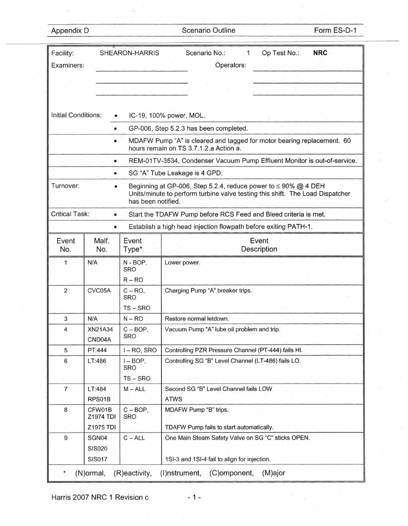
Initial Conditions: • IC-19, 100% power, MOL.
'. GP-006, Step 5.2.3 has been completed.
• MOAFW Pump "A" is cleared and tagged for motor bearing replacement. 60hours remain on TS 3.7.1.2.a Action a.
• REM-01TV-3534, Condenser Vacuum Pump Effluent Monitor is out-of-service.
• SG "A" Tube Leakage is 4 GPO.
Turnover:
Critical Task:
• Beginning at GP-006, Step 5.2.4, reduce power to :::; 90% @ 4 DEHUnits/minute to perform turbine valve testing this shift. The Load Dispatcherhas been notified.
• Start the TOAFW Pump before RCS Feed and Bleed criteria is met.
• Establ.ish a high head injection flowpath before exiting PATH-1.
EventNo.
2
3
4
5
6
7
8
9
Malt.No.
N/A
CVC05A
N/A
XN21A34
CN004A
PT:444
LT:486
LT:484
RPS01B
CFW01BZ1974 TOI
Z1975 TOI'
SGN04
SIS020
SIS017
EventType*
N - BOP,SRO
R-RO
C~RO,
SRO
TS ~SRO
N-RO
C- BOP,SRO
I-RO, SRO
I-BOP,SRO
TS-SRO
M-ALL
C - BOP,SRO
C-ALL
EventDescription
Lower power.
.Charging Pump "A" breaker trips.
Restore normal letdown.
Vacuum Pump-"A" lube oil proble.m and trip.
Controlling PZR Pressure Channel (PT-444) fails HI.
Controlling SG. "B" Level Channel (LT-486) fails LO.
Second SG "B" Level Channel fails LOW
ATWS
.MOAFW Pump "B" trips.
TOAFW Pump fails to start automatically.
One Main Steam Safety Valve on SG "C" sticks OPEN.
1SI-3 and 1SI-4 fail to align for injection.
* (N)ormal, (R)eactivity, (I)nstrument, (C)omponent, (M)ajor
Harris 2007 NRC 1 Revision c - 1 -
Scenario ,Event Description
Shearon-Han is 2007 NRC Scenario 1
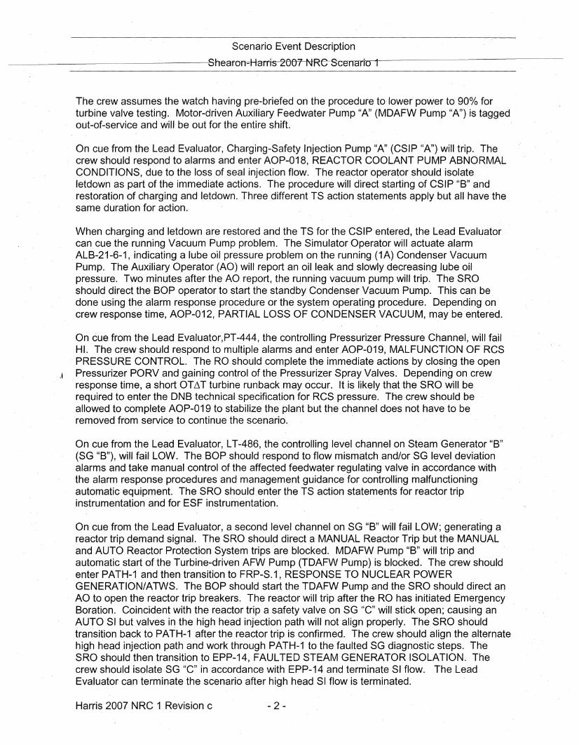
The crew assumes the watch having pre-briefed on the procedure to'iower' power to 900/0 forturbine valve testing. Motor-driven Auxiliary Feedwater Pump "A" (MDAFW Pump "A") is taggedout-of-service and will be out for the entire shift.
On cue from the Le,ad Evaluator, Charging-Safety Injection Pump "A" (CSIP"A") will trip. Thecrew should respond to alarms and enter AOP-0'18, REACTOR COOLANT PUMP ABNORMALCONDITIONS, due to the loss of seal injection flow. ,The reactor operator should isolateletdown as part of the immediate actions. The procedure will direct starting of CSIP "B" andrestoration of charging and letdown. Three different TS action statements apply but all have thesame duration for action.,
When charging and letdown are restored and theTS for the CSIP entered, the Lead Evaluatorcan Gue the running Vacuum Pump problem. The Simulator Operator will actuate alarmALB-21-6-1, indicating a lube oil pressure pro'blem on the running (1A) Condenser VacuumPump. The Auxiliary Operator (AO) will report an oil leak and slowly,decreasing lube oil'pressure. Two minutes after the AO report, the running vacuum pump will trip. TheSROshould direct the BOP operatorto start the standby Condenser Vacuum Pump. This can bedone using the alarm resp,onse procedure or the system operating procedure. Depending oncrew response time, AOP-012, PARTIAL LOSS OF CONDENSER VACUUM, may be entered.
On cue from the Lead Evaluator,PT-444, the controlling Pressurizer Pressure Channel, will failHI. The, crew should respond to multiple alarms and enter AOP-019, MALFUNCTION OF RCS'PRESSURE CONTROL. The ROshould complete the immediate actions by closing the open
" Pressurizer PORV and'gaining control of the Pressurizer Spray Valves. Depending on crewresponse time, a short OT~T turbine runback may occur. It is likely that the SRO will berequired to enter the·DNB technical specification for RCS pressu're. The crew should beallow,ed to complete AOP-019 to stabilize the plant but the channel does not have to be'removed from service to continue the scenario.
On cue from the Lead Evaluator, LT-486, the controlling level channel on Steam Generator "B"(SG "B"), will fail' LOW. The BOP should respond to flow mismatch and/or SG level deviationalarms and take manual control of the affected feedwater regulating valve in accordance withthe alarm response procedures and management guidance' for controlling malfunctioningautom\atic equipment. The SRO should ,enter the TS action statements for reactor tripinstrumentation and for ESF instrumentation.
On cue from the Lead Evaluator, a second level channel on SG "B" will fail LOW; generating areactor trip demand signal. The SRO should direct a MANUAL Reactor Trip but the MANUALand AUTO Reactor Protection System trips'are blocked. MDAFW Pump "B" will trip andautomatic start of the Turbine~driven AFW Pump (TDAFW Pump) is blocked. The crew shouldenter PATH-1 and then transition to FRP-S.1, RESPONSE TO NUCLEAR POWERGENERATION/ATWS. The BOP should start the TDAFW Pump and the SRO'should direct anAO to open the reactor trip breakers. The reactor will trip after the RO has initiated EmergencyBoration. Coincident with the reactor trip a safety valve on SG "c" will stick open,; causing anAUTO SI but valves in the high head injection path will not align properly. The SRO shouldtransition back to PATH-1 'after the reactor trip is confirmed. The crew should align the alternatehigh head injection path and work through PATH-1 to the faulted SG diagnostic steps. TheSRO should then transition to' EPP-14, FAULTED STEAM GENERATOR ISOLATION. Th'ecrew should isolate SG "c" in accordance with EPP-14 and terminateSI flow. The LeadEvaluator can terminate the scenario after high head SI flow is terminated.
Harris 2007 NRC 1 Revision c ,- 2 -
Scenario Event Description
Shearon Harris 2007 NRC Scenario 1
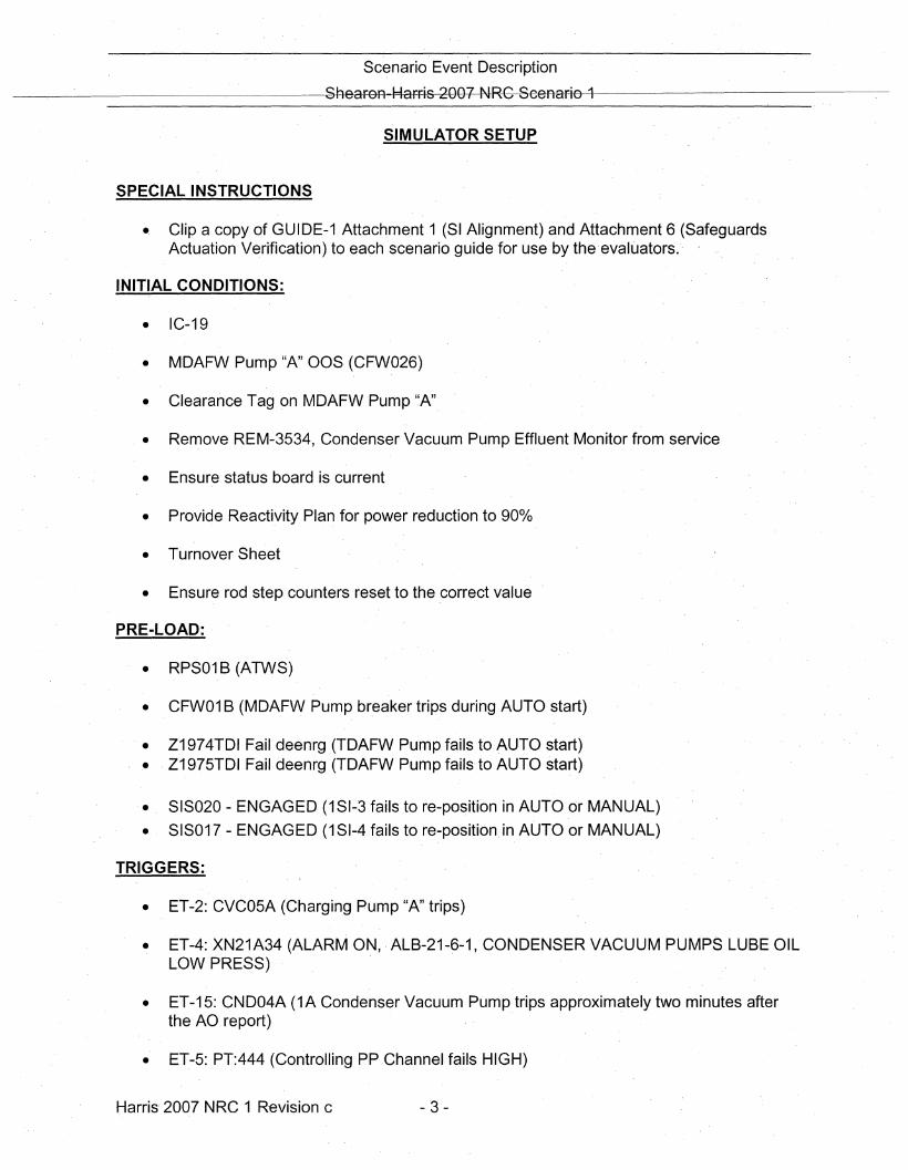
SIMULATOR SETUP
SPECIAL INSTRUCTIONS
., Clip a copy of GUIDE-1 Attachment 1 (SI Alignment) and Attachment 6 (SafeguardsActuation Verification) to each scenario guide for use by the'evaluators.'
INITIAL CONDITIONS:
• IC-19
• MD'AFW Pump "A" OOS (CFW026)
• Clearance Tag on MDAFW Pump "A"
• Remove REM-3534, Condenser Vacuum Pump Effluent Monitor from service
• Ensure status board is current
• Provide Reactivity Plan for power reduction to 900Jb
• Turnover Sheet
• Ensure rod step counters reset to the ,correct value
PRE-LOAD:
• RPS01 B (ATWS)
• CFW01 B (MDAFW Pump breaker trips during AUTO start)
'. Z1974TDI Fail deenrg (TDAFW Pump fails to AUTO start)• Z1975TDI Fail deenrg (TDAFW Pump fails,to AUTO start)
• SIS020 - ENGAGED (1SI-3 fails to re-position in AUTO or MANUAL)
• SIS017 - ENGAGED (1SI-4 fails to re-position,in AUTO or MANUAL)
TRIGGERS:
• ET-2: CVC05A (Charging Pump "A" trips)
• ET-4:XN21A34 (ALARM ON, ALB-21-6-1, CONDENSER VACUUM PUMPS LUBE OILLOW PRESS) ,
• ET-15: CND04A (1A Condenser Vacuum Pump trips approximately two minutes afterthe AOreport)'
• ET-5: PT:444 (Controlling PP Channel fails HIGH)
Harris' 2007 NRC 1 Revisionc - 3 -
Scenario .Event Description
Shearon Harrrs 2007 NRC Scenario 1
• ET-6: .LT:486 (SG "B" Level Channel fails LOW)
• ET-7: LT:484 (SG "B" Level Channel fails LOW)
• ET-16: Clear RPS01B
• ET-9: SGN04C (Main Steam Safety Valve fails OPEN on SG "C")
• ET-18 and ET-19: Guide 1, Attachment 6 field actions
Harris 2007 NRC 1 Revision c .- 4 -
Appendix 0 Operator Action Form ES-D-2
Op-Test No.:
Event Description: Lower Power
_____ Page - 5 of _3_8__11
I- Time Position Applicant's Actions or Behavior
Booth Operator Instructions:
Indications Available:
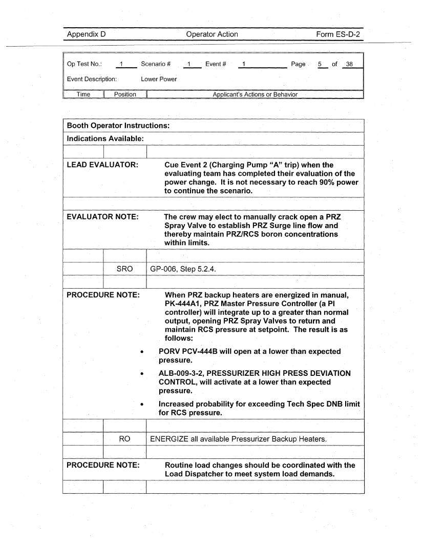
LEAD EVALUATOR: Cue Event 2- (Charging Pump "A" trip) when the_evaluating team has completed their evaluation of thepower change. It is not necessary to reach 900/0 powerto continue the scenario.
EVALUATOR NOTE: The crew may elect to manually crack open a PRZSpray Valve to establish PRZ Surge line flow andthereby maintain PR-Z/RCS boron concentrationswithin limits.
SRO - GP-006, Step 5.2.4.
PROCEDURE NOTE: When PRZbackupheaters are energized in manual,PK-444A1; PRZ Master Pressure Controller (a PIcontroller) will integrate up to a greater than normaloutput, opening PRZ Spray Valves to return andmaintain RCS pressure at setpoint. The result is asfollows:
• PORV PCV-444B will open at a lower than expectedpressure.
• AlB-009-3-2, PRESSURIZER HIGH PRESS DEVIATIONCONTROL, will activate at a lower than expectedpressure.
• Increased probability for exceeding Tech Spec DNB limitfor RCS -pressure~
RO ENERGIZE all available Pressurizer Backup Heaters.
PROCEDURE NOTE: Routine load changes should be coordinated with theLoad Dispatcher to meet system load demands.
Appendix D Operator Action Form ES-D-2
Op'Test No.: __ Scenario # 1 Event # _____ Page 6 .of _3_8~,
Event Description: Lower Power
I' Time Position Applicant's Actions or Behavior
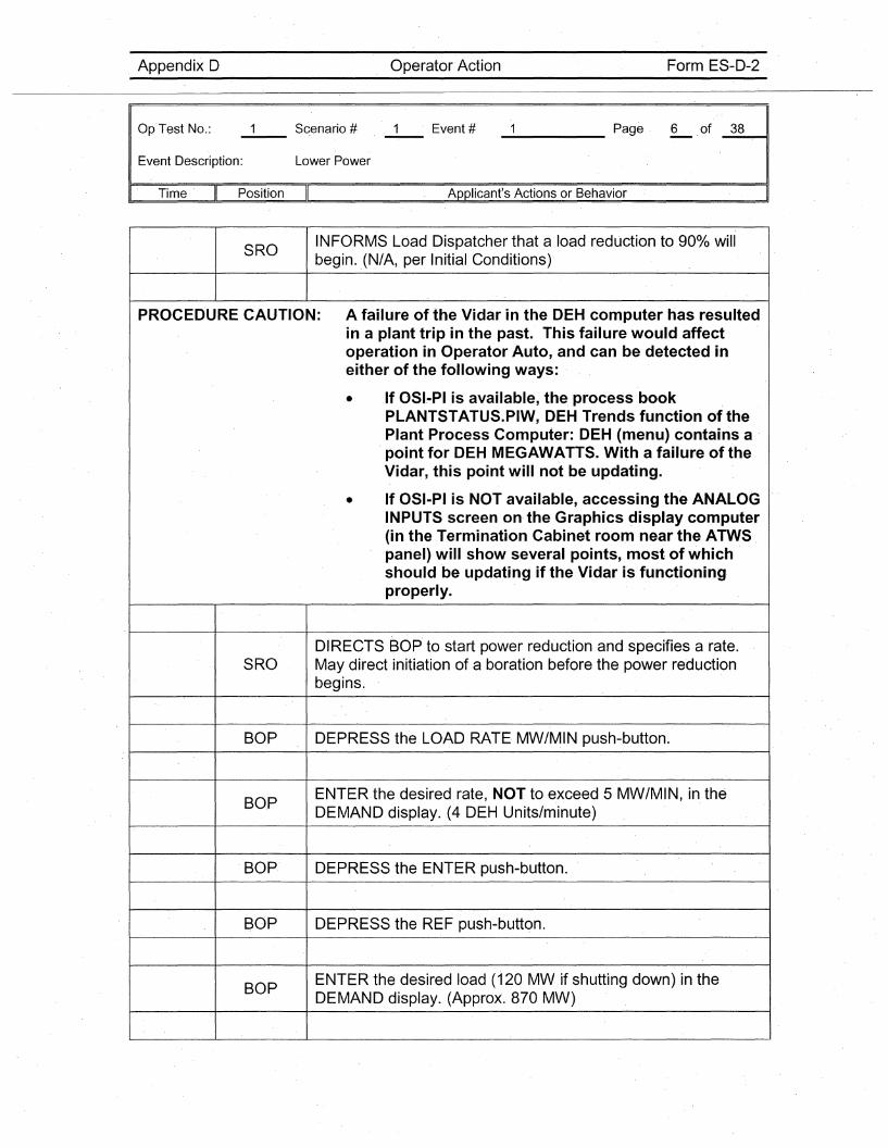
SROINFORMS Load Dispatcher that a load reduction to 900/0 willbegin. ,(N/A, per Initial Conditions)'
PROCEO'URE CAUTION: A failure of the Vidar in the OEH computer has resultedin a plant trip in the past. This failure would affectoperation in Operator Auto, and can be detected ineither of the following ways:
• If OSI-Plis available, the process bookPLANTSTATUS.PIW, OEH Trends function of thePlant Process Computer: OEH (menu) contains a .point for OEH MEGAWATTS. With a failure of theVidar, this point will not be updating.
• If OSI-PI is NOT available, accessing the ANALOGINPUTS screen on· the Graphics display computer(in the Termination Cabinet room near the ATWSpanel) will show several points, most of whichshould be updating if the Vidar is functioning·properly.
DIRECTS BOP' to start power reduction and specifies a rate.SRO May direct initiation of a boration before the power reduction
begins.
BOP DEPRESS the LOAD RATE MW/MIN push-button.
BO.PENTER the desired rate, NOT to exceed 5 MW/MIN, in. theDEMAND display. .(4 DEH Units/minute)
BOP.' DEPRESS the ENTER push-button.
BOP DEPRESS the REF push-button.
BOPENTER the desired load (120 MW if shutting down) in theDEMAND display. (Approx. 870 MW)
Appendix D Operator Action Form ES-D~2
Op Test No.:
Event Description:
Time II- Position
Lower Power
_____ Page 7 of _3_8__11
Applicant's Actions or Behavior
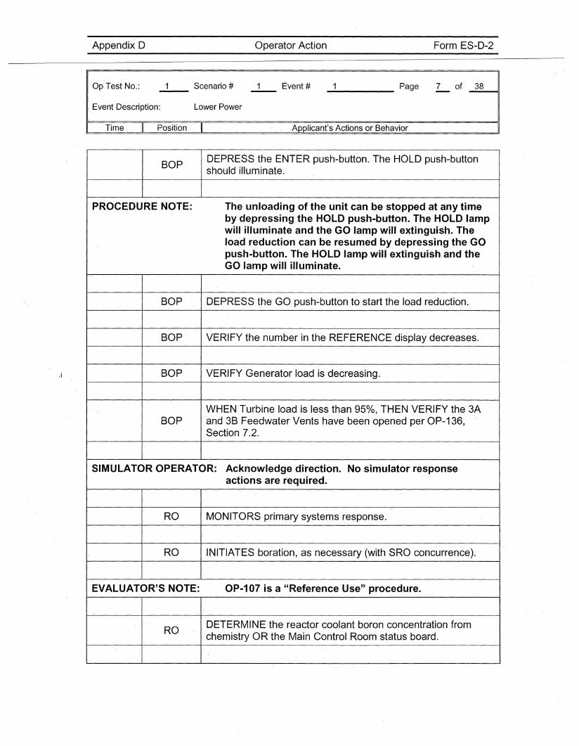
BOP DEPRESS the ENTER push-butto~. The HOLD push-buttonshould illuminate.
PROCEDURE NOTE: The unloading of the unit can be stopped at any timeby depressing the HOLD push-button. The HOLD lampwill illuminate and the GO lamp will extinguish. Theload reduction can be resumed by depressing the GOpush-button. The HOLD lamp will extinguish and theGO lamp will illuminate.
BOP DEPRESS the GO push-button to start the load reduction.
BOP VERIFY the number in the REFERENCE display decreases.
BOP VERIFY Generator load is decreasing.
WHEN Turbine load is less than 950/0, THEN VERIFY the 3ABOP and 3B Feedwater Vents have been opened per OP-136,
Section 7.2.
SIMULATOR OPERATOR: Acknowledge direction. No simulator responseactions are required.
RO MONITORS primary systems response.
RO INITIATES boration, as necessary (with SRO concurrence).
EVALUATOR'S NOTE: OP-107 is a "Reference Use" procedure.
RODETERMINE the reactor coolant boron concentration fromchemistry OR the Main Control Room status board.
Appendix D Operator Action Form ES-D-2
Op'Test No.:
Event Description: Lower Power
_____ Page 8 ,of _3_8---11
" Time Position Applicant's Actions or Behavior
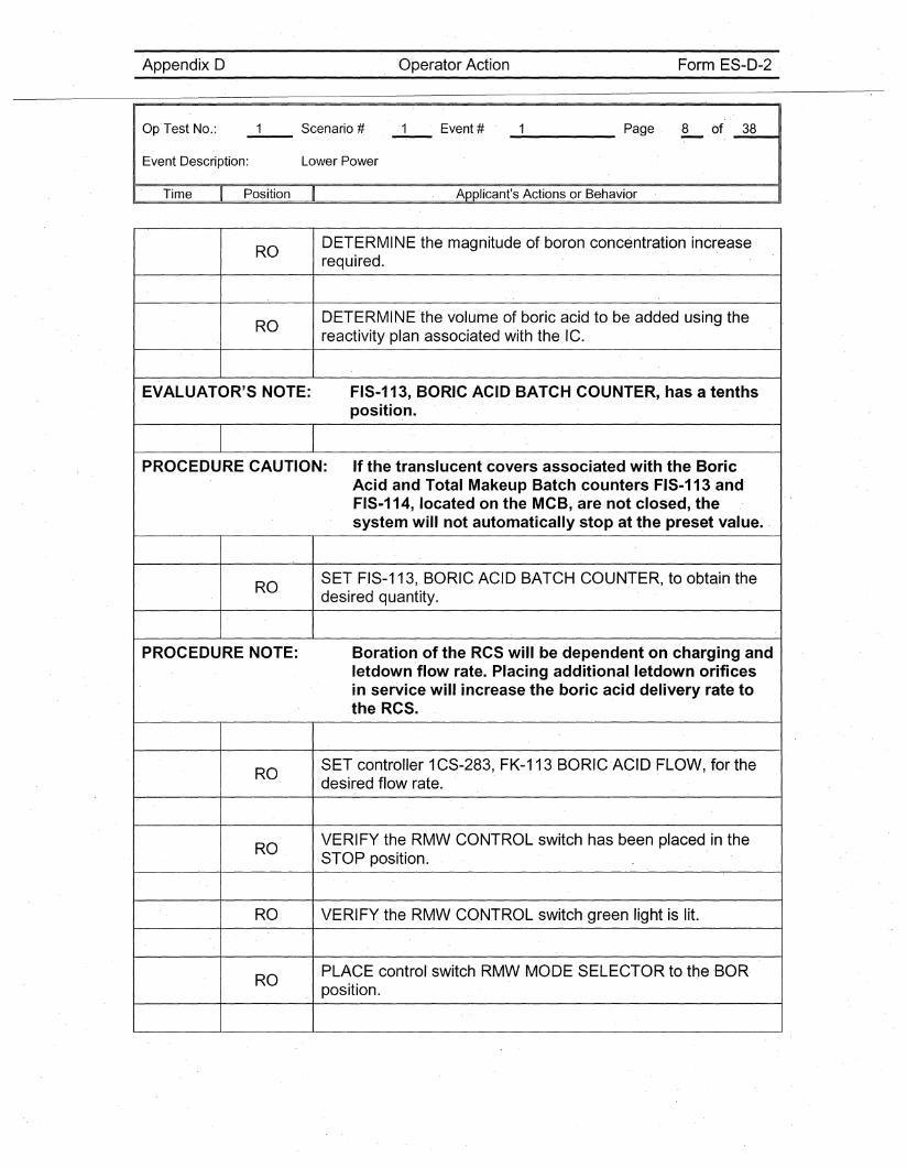
RODETERMINE the magnitude of boron concentration increaserequired.
RODETERMINE the volume of boric acid to be added using thereactivity'plan associated with the IC.
EVALUATOR'S NOTE: FIS-113, ,BORIC ACID BATCH COUNTER, has a tenthsposition.
PROCEDURE CAUTION: If the translucent covers associated with the BoricAcid and Total Makeup Batch counters FIS-113 and'FIS-114, located on the MCB, are not closed, thesystem will not automatically stop at the preset value. '
ROSET FIS-113, BORIC ACID BATCH COUNTER, to obtain thedesired quantity~
PROCEDURE NOTE: Boration of the RCS will be dependent on charging andletdown 'flow rate. Placing additional, letdown orificesin service will increase the boric acid delivery rate tothe RCS.
ROSET controller 1CS-283, FK-113 BORIC'ACID FLOW, for thedesired flow rate.
ROVERIFY the RMW CONTROL switch has been placed in theSTOP position.
RO VERIFY the RMW CONTROL switc'h green light is lit.
ROPLACE control'switch RMW MODE SELECTOR tothe ,BOR,position.
Appendix 0 Operator Action Form ES-O-2
Op Test No.:
Event Description: Lower Power
_____ Page 9 of' _3_8--11
Time Position Applicant's Actions or Behavior , I
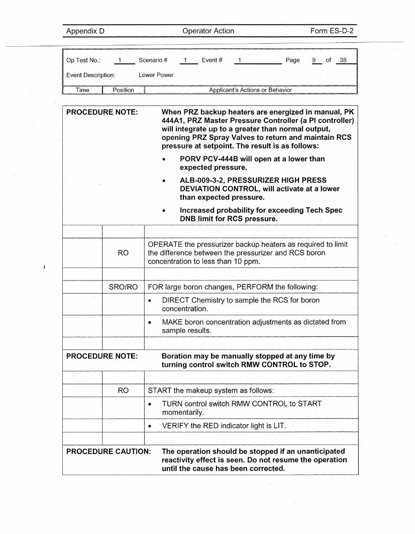
PROCEDURE NOTE: When PRZ backup heaters are, energized in manual, PK444A1, PRZ Master Pressure Controller (a PI controller)will integrate up to a greater than normal output,opening PRZ Spray Valves to return and maintain RCSpressure at setpoint. The result isas follows:
• PORV PCV-444B will open at a lower thanexpected pressure.
• ALB-009-3-2, PRESSURIZER HIGH PRESSDEVIATION CONTROL, will activate at a lowerthan expected pressure.
• Increased probability for exceeding Tech SpecDNB ,limit for RCS pressure.
OPERATE the pressurizer backup heaters as required to limitRO the difference between the pressurizer and RCS boron
concentration to less than 10 ppm.
SRO/RO FOR large boron ,changes, PERFORM the following:
• DIRECT Chemistry to sample the RCS for boronconcentration.
• MAKE boron concentration adjustments as dictated fromsample results.
PROCEDURE NOTE: Boration may be manually stopped at any time byturning control switch RMW CONTROL to STOP.
RO START the makeup system as follows:
• TU'RN control switch RMW CONTROL to START,momentarily.
• VERIFY the RED indicator light is LIT.
PROCEDURE CAUTION: The operation should be stopped if an unanticipatedreactivity effect is seen. Do not resume the operationuntil the cause has been corrected.
OperatorActionAppendix D
Op·Test No.:
Event Description: Lower Power
Form ES-D-2
Page 10 of 38----- ----41
I· Time Position Applicant's Actions or Behavior
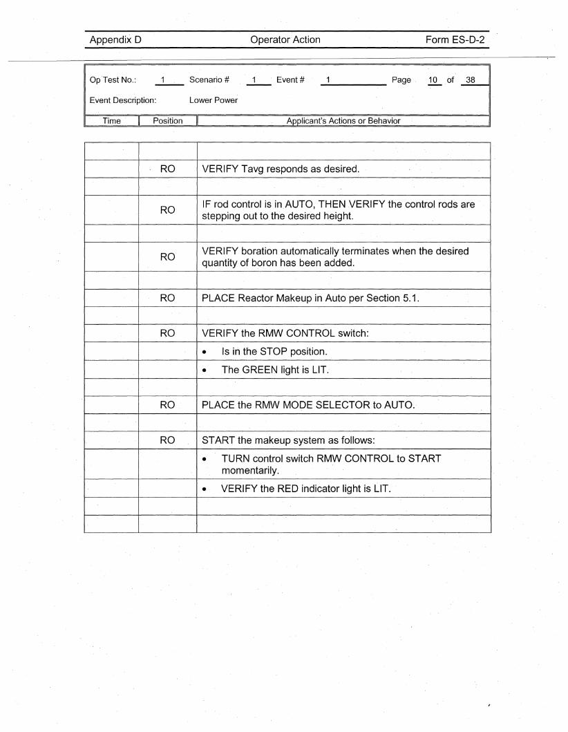
RO VERIFY Tavg responds as desired.
ROIF rod control is in AUTO, THEN VERIFY the control rods arestepping out to the desired height.
ROVERIFY boration automatically terminates when the desiredquantity of boron has been added.
RO PLACE Reactor Makeup in Auto per Section. 5.1.
RO VERIFY the RMW CONTROL switch:
• Is in the STOP position.
• The GREEN light is LIT.
RO PLACE the RMW MODE SELECTOR to AUTO.
RO START the makeup system as follows:
• TURN control switch RMW CONTROL to STARTmomentarily.
• VERIFY the RED indicator light is LIT.
Appendix D Operator Action Form ES-D-2
Op Test No.:
Event Description:
_2_a_n_d_3___ Page 11 of _3_8---11
Charging Pump "A" Breaker Trips; Letdown restoration
Time Position Applicant's Actions or Behavior
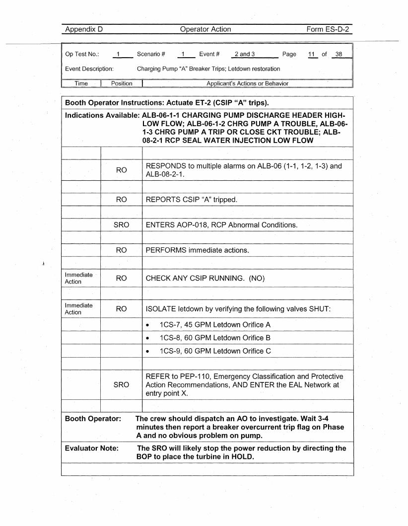
Booth Operator Instructions: Actuate ET-2 (CSIP "A" trips).
Indications Available: ALB-06-1-1 CHARGING PUMP DISCHARGE HEADER HIGH-LOW FLOW; ALB-06-1-2 CHRG PUMP A TROUBLE, ALB-06·1-3 CHRG PUMP A TRIP OR CLOSE CKT TROUBLE; ALB-08-2-1 RCP SEAL WATER INJECTION LOW·FLOW
RORESPONDS to multiple alarms on ALB-06 (1-1, 1~2, 1-3) andALB~08-2-1.
RO REPORTS CSIP "A" tripped.
SRO ENTERS AOP-018, RCP Abnormal Conditions.
RO PERFORMS immediate actions.
Immediate RO CHECK ANY CSIP RUNNING. (NO)Action
Immediate RO ISOLATE letdown by verifying the following valves SHUT:Action
• 1CS-7, 45 GPM Letdown Orifice A
• 1CS-8, 60 GPM Letdown Orifice B
• 1CS-9, 60 GPM Letdown Orifice C
REF~R to PEP-11 0, Emergency Classification and ProtectiveSRO Action Recommendations, AND ENTER the EAL Network at
entry point x.
Booth Operator: The crew should dispatch an.AO to investigate. Wait 3-4minutes then report a breaker overcurrent trip flag on PhaseA and no obvious problem o.n pump.
Evaluator Note: The SROwililikely stop the power reduction by directing theBOP to place the turbine in HOLD.
Appendix D Operator Action Form ES-D-2
Op Test No.:
Event Description:
Time II ,Position'
_2_a_n_d_3 Page 12 of _3_8---11
Charging Pump "A" Breaker Trips; Letdown restoration
Applicant's Actions or Behavior
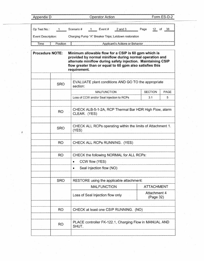
Procedure NOTE: Minimum allowable flow for a CSIP is 60 gpm which isprovided by normal miniflow during normal operation andalternate miniflow during safety injection. Maintaining CSIPflow greater than or equal to 60 gpm also satisfies thisrequirement.
SROEVALUATE plant conditions AND GO TO the appropriate,section:
MALFUNCTION SECTION PAGE
Loss of CCW and/or Seal ,Injection to RCPs 3.1 5
RO,CHECK ALB-5~1-2A, RCP Thermal Bar HDR High Flow, alarmCLEAR. (YES)
SROCHECK ALL RCPs operating within the limits of Attachment 1.(YES)
RO CHECK ALL RCPs RUNNING. (YES)
RO CHECK the following NORMAL for ALL RCPs:
• CCW flow (YES)
• Seal Injection flow (NO)
SRO RESTORE using the applicable attachment:
MALFUNCTION ATTACHMENT
Loss of Seal Injection flow onlyAttachment 4
(Page 32)
RO CHECK at least one CSIP RUNNING. (NO)
ROPLACE controller FK-122.1, Charging Flow in MANUAL ANDSHUT.
Appendix D Operator Action Form ES-D-2
Op Test No.:
Event Description:
_2_a_n_d_3___ Page 13 of. _3_8----11
Charging Pump "A" Breaker Trips; Letdown restoration
Time Position Applicant's Actions or Behavior
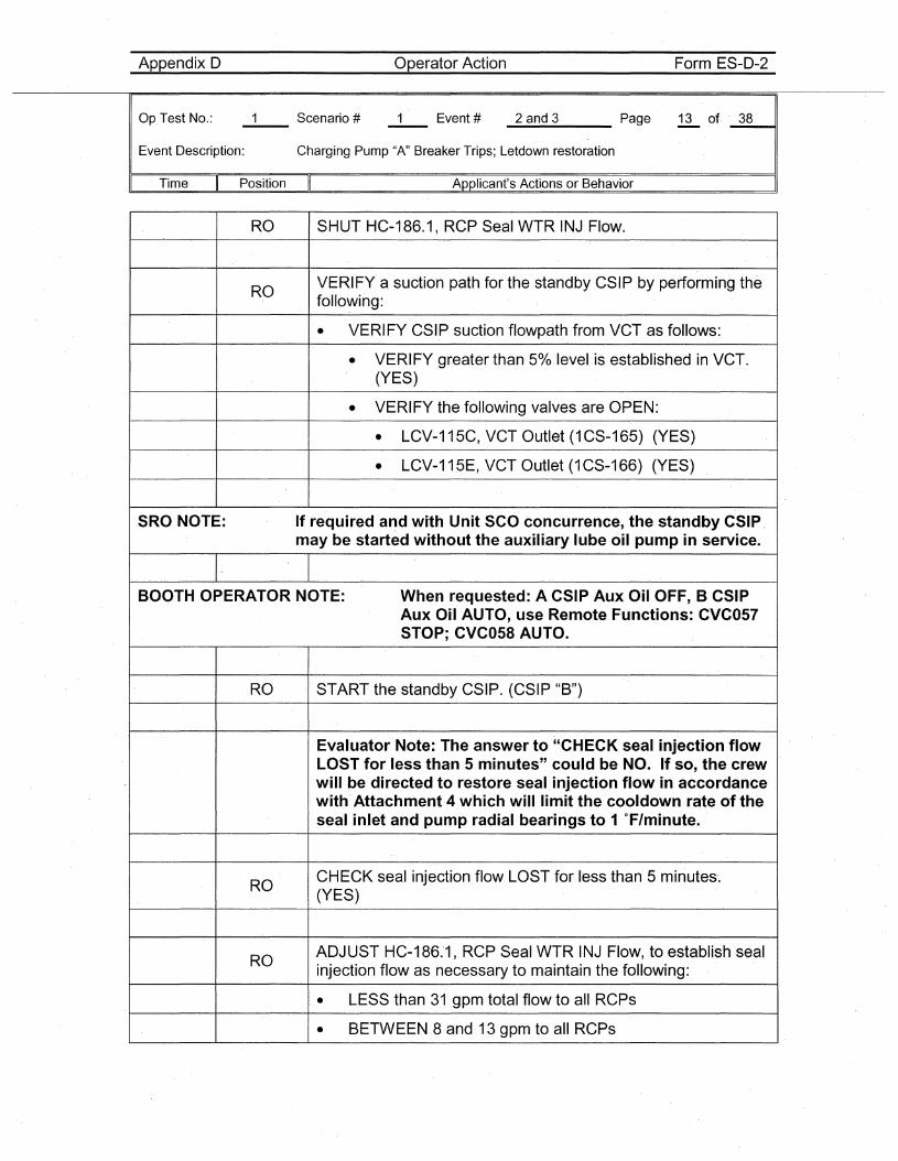
RO SHUT HC-186.1, RCP Seal WTR INJ Flow.
ROVERIFY a suction path for the standby CSIP by performing thefollowing:
• VERIFY CSIP suction flowpath from VCT as follows:
• VERIFY greater than 5% level is established in VCT.(YES)
• VERIFY the following valves are OPEN:
• LCV-115C, VCT Outlet (1CS-165) (YES)
• LCV-115E, VCT Outlet (1 CS-166) (YES)
SRO NOTE: If required and with Unit SCO concurrence, the standby CSIP,may be started without the auxiliary lube oil pump in service.
BOOTH OPERATOR NOTE: When requested: A CSIP Aux Oil OFF, B CSIPAux Oil AUTO, use Remote Functions: CVC057STOP; CVC058 AUTO.
RO START the standby CSIP. (CSIP "B")
Evaluator Note: The answer to "CHECK seal injection flowLOST for less than 5 minutes" could be NO. If so, the crewwill be directed to restore seal injection flow in accordancewith' Attachment 4 which will limit the cooldown rate of theseal inlet and pump radial bearings to 1°F/minute.
ROCHECK seal injection flow LOST for less than 5 minutes~
(YES)
ROADJUST HC-186.'1, RCP Seal WTR INJ Flow, to establish sealinjection flow as necessary to maintain the following:
• LESS than 31 gpm total flow to all RCPs
• BETWEEN 8 and 13 gpm to all RCPs
Appendix 0 Operator Action Form ES-D-2
Op Test No.:
Event Description:
_2_a_n_d_3 Page 14 of _3_8~,
Charging Pump "A" Breaker Trips; Letdown restoration
Time Position
SRO
RO
SRO
Applicant's Actions or Behavior
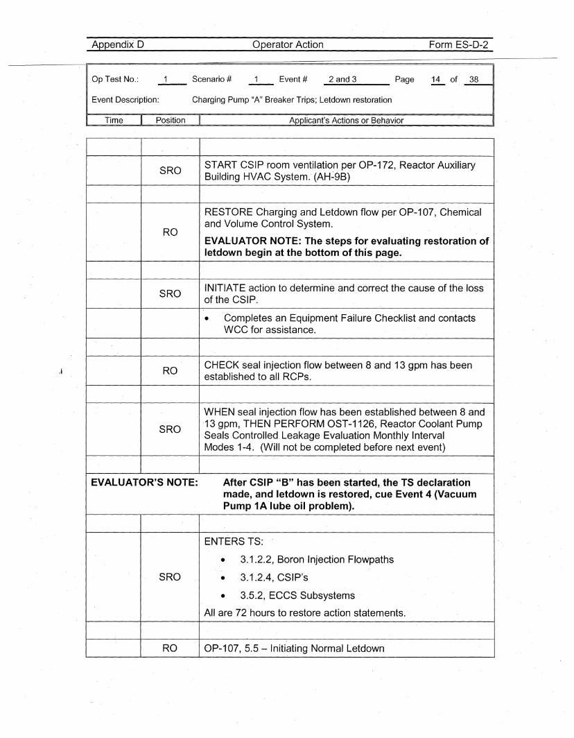
START CSIP room ventilation per OP-172, Reactor AuxiliaryBuilding HVAC System.' (AH~9B)
RESTORE Charging and Letdown flow per OP-107, Chemicaland Volume Control System~
EVALUATOR NOTE: The steps for evaluating restoration ofletdown begin at the bottom of thi's page.
INITIATE action to determine and correct the cause of the lossof the CSIP.
• 'Completes an Equipment Failure Checklist and contactswee for assistance.
CHECK seal injection flow between 8 and 13 gpm has b,eenestablished to all RCPs.
WHEN seal injection flow has been established between 8 and13 gpm, THEN PERFORM OST-1126, Reactor Coolant PumpSealsControlled,Leakage Evaluation Monthly IntervalModes 1-4. (Will not be completed before next event)
EVALUATOR'S NOTE: After CSIP "8" has been started, the TS declarationmade, and letdown is restored, cue Event 4 (VacuumPump 1A'lube oil problem).
ENTERS TS,:
• 3.1.2.2, Boron Injection Flowpaths
SRO • 3.1.2.4, CSIP's
• 3.5.2, ECCS Subsystems
All are 72 hours to restore action statements.
RO OP-107, 5.5 - Initiating Normal Letdown
Appendix D Operator'Action Form ES-D-2
Op.Test No.:
Event Description:
_2_a_n_d_3 Page 15 of· _.3_811
Charging Pump "A" Breaker Trips; Letdown restoration
. Time II Position II Applicant's Actions or Behavior
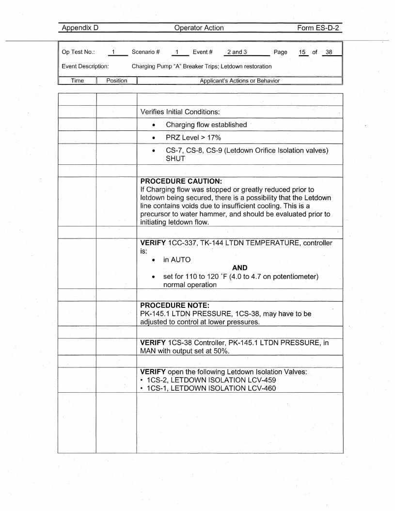
Verifies Initial Conditions:
• Charging flow established
• PRZ Level> 17%
• CS-7, CS-8, CS-9 (Letdown Orifice Isolation valves)SHUT
PROCEDURE CAUTION:If Charging flow was stopped or greatly reduced prior toletdown being secured, there is a possibility that the Letdownline contains voids due to insufficient cooling. This is a .precursor to water hammer, and should be evaluated prior toinitiating letdown flow.
VERIFY 1CC~337, TK-144 LTDN TEMPERATURE, controlleris:
• in AUTOAND
• set for 110 to 120 OF (4.0 to 4.7 on potentiometer)normal operation
PROCEDURE NOTE:PK-145.1 LTDN· PRESSURE, 1CS-38, may havE3 to beadjusted to control at lower pressures.
VERIFY 1CS-38 Controller, PK-145.1 LTDN PRESSURE, inMAN with output set at 50%.
VERIFY open the following Letdown Isolation Valves: .- 1CS-2, LETDOWN ISOLATION LCV-459-1 CS-1, LETDOWN ISOLATION LCV-460
Appendix 0 Operator Action Form ES-O-2
Op Test No.:
Event Description:
_2_a_n_d_3 Page 16 of _3_8~,
Charging Pump "A" Breaker Trips; Letdown restoration
Time Position Applicant's Actions or Behavior
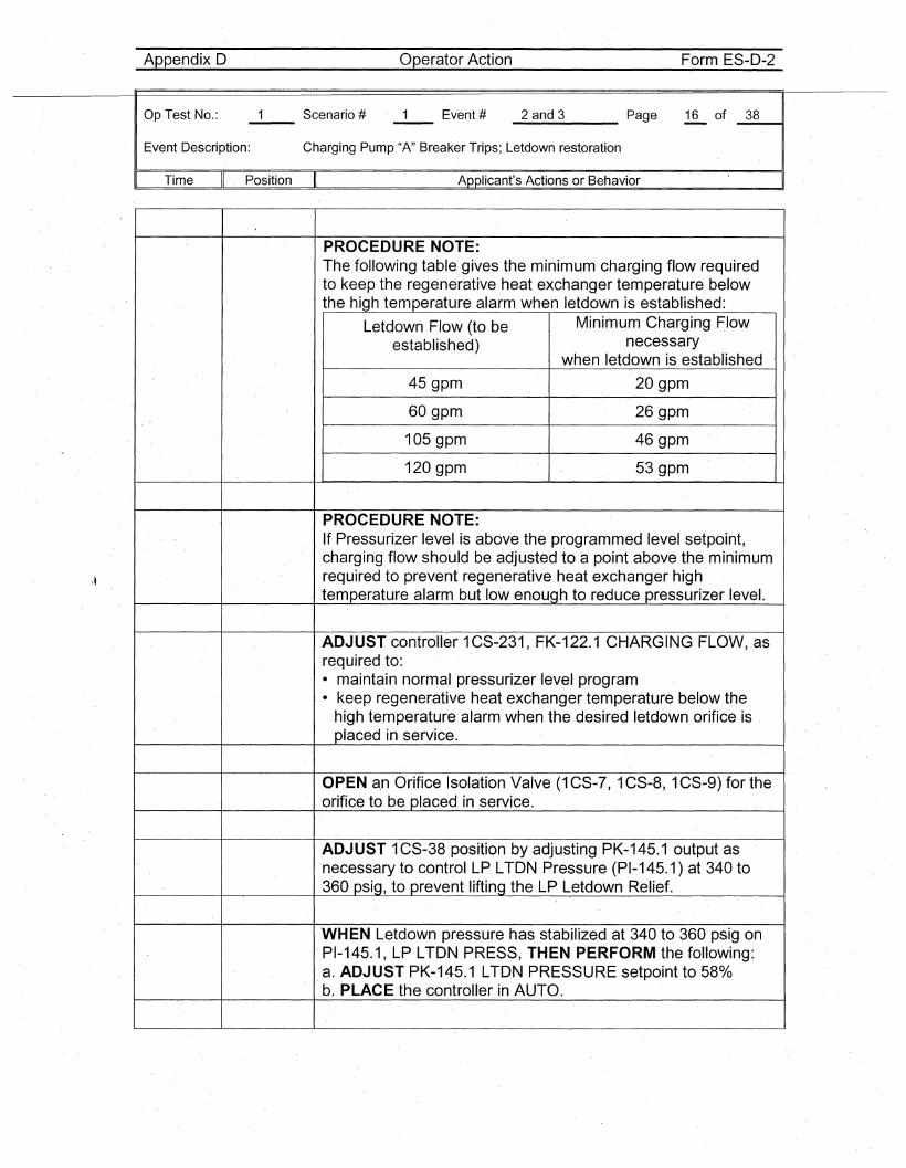
PROCEDURE NOTE:The following table gives the minimum' charging flow requiredto keep the regenerative heat exchanger temperature belowthe high temperature alarm when letdown is established:
Letdown Flow (to be Minimum Charging Flow
established) necessarywhen letdown is 'established
45 gpm 20 gpm
60 gpm 26gpm
105 gpm 46gpm
120,gpm 53 gpm
PROCEDURE NOTE:If Pressurizer level is above the programmed level setpoint,ch'arging flow should be adjusted to a point above the minimumrequired to prevent regenerative heat exchanger hightemperature alarm but "low enough to reduce pressurizer level.
ADJUST controller 1CS-231, FK-122.1 CHARGING FLOW, asrequired to:• maintain normal pressurizer level program• keep regenerative heat exchanger temperature below the
high temperature alarm when the desired letdown orifice isplaced in serVice.
OPEN a,n Orifice Isolation Valve (1 CS-7, 1CS-8, 1CS-9) for theorifice to be placed in'service.
ADJUST 1CS-38 position by adjusting PK-145.1 output asnecessary to control LP LTON Pressure (PI-145.1) at 340 to360 psig, to prevent lifting the LP Letdown Relief.
WHEN Letdown pressure has stabilized at 340 to 360 psig on,PI-145.1, LP LTON PRESS, THEN PERFORM the following:a. ADJUST PK-145.1, LTON PRESSUREsetpoint to 580/0b. PLACE the controller in AUTO.
Appendix 0 Operator Action Form ES-D-2
0p,Test No.:
Event Description:
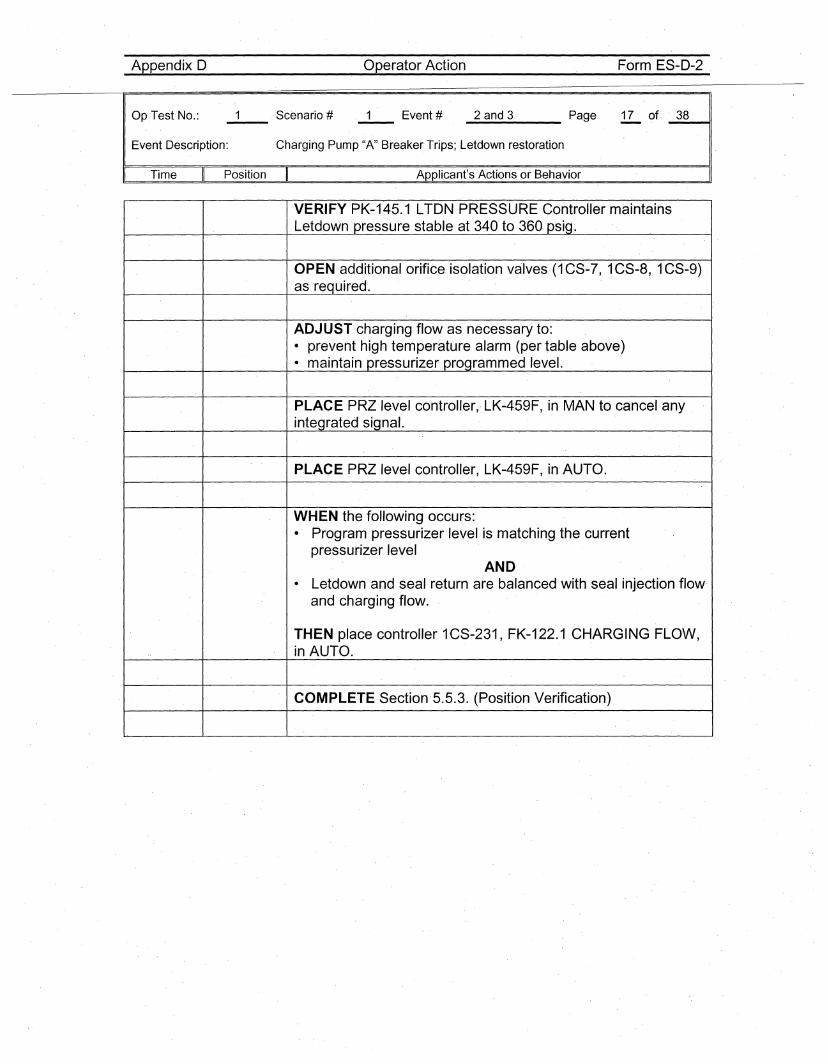
_2_a_n_d_3 Page 17 of, _3_8__11
Charging Pump "A" Breaker Trips; Letdown restoration
, Time Position Applicant's Actions or Behavior
VERIFY PK-145.1 LTON PRESSURE Controller maintainsLetdown pressure stable at 340 to 360, psig~
OPEN additional orifice isolation valves (1 CS-7, 1CS-8, 1CS-9)as required.
ADJUST charging flow as necessary to:• prevent high temperature alarm (per table above)• maintain pressurizer programmed level.
PLACE PRZlevel controller,.LK-459F, in MAN to cancel anyintegrated signal.
PLACE PRZ level controller, LK-459F, in AUTO.
WHEN the following occurs:. Program pressurizer level is matching the currentpressurizer level
AND. Letdown and seal return are balanced with seal inJection flow'and charging flow.
THEN place controller 1CS-231, FK-122.1 CHARGING FLOW,in AUT,O.
COMPLETE Section'5.5.3. (Position Verification)
Appendix D Operator Action Form ES-D-2
0p,Test No.:
Event Description:
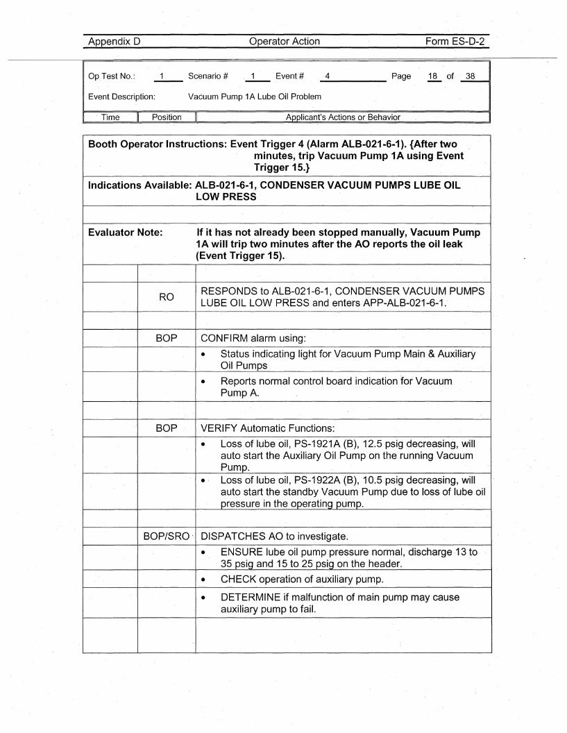
_4 Page 18 of. _3_8---41
Vacuum Pump 1A Lube Oil Problem
, Time Position Applicant's Actions or Behavior
Booth Operator Instructions: Event Trigger 4 (Alarm ALB-021-6-1). {After twominutes, trip Vacuum Pump 1'A using EventTrigger 15.}
Indications Available: ALB-021-6-1, CONDENSER VACUUM PUMPS LUBE OILLOW PRESS
Evaluator Note: If it has not already been stopped manually, Vacuum Pump1A will trip two minutes after the AO reports the oil leak(Event Trigger 1.5).
RORESPON'DS to ALB-021-6-1, CONDENSER VACUUM PUMPSLUBE OIL LOW PR'ESS and enters APP-ALB-021-6-1.
BOP CONFIRM 'alarm using:
• Status indicating light for Vacuum Pump Main &AuxiliaryOil Pumps
• Reports normal control board indication for VacuumPump A.
BOP VERIFY Automatic Functions:
• Loss of lube oil, PS-1921A (B), 12.5psigdecreasing, willauto start the Auxiliary Oil Pump on the running VacuumPump..' Loss of lube oil, PS-1922A (B), 10.5psig decreasing, willauto start the standby Vacuum Pump due to loss of lube oilpressure in th,e operating pump.
BOP/SRO' DISPATCHES AO to investigate.
• ENSURE lube oil pump pressure normal, 'discharge ,13 to35 psig and 15 to 25 psig on the header.
• CHECK operation of auxiliary pump.
• DETERMINE,if malfunction of main pump may causeauxiliary pump to fail.
Appendix 0 Operator Action Form ES-D-2
Op Test No.:
Event Description:
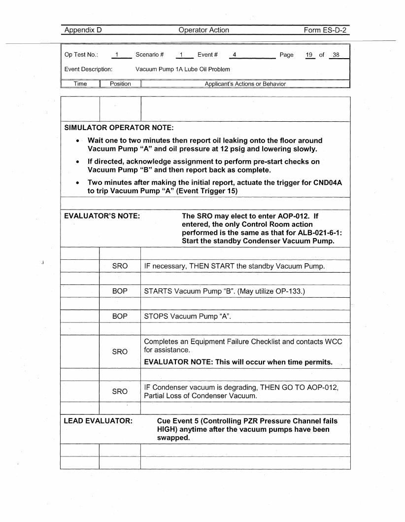
_4 Page 19 of _3_8---ot1
Vacuum Pump 1A Lube Oil Problem
Time Position Applicant's Actions or Behavior
SIMULATOR OPERATOR NOTE:
• Wait one to two minutes then report oil leaking onto the floor aroundVacuum Pump "A" and oil pressure at 12 psig,and lowering slowly.
• If directed, acknowledge assignment to perform pre-start checks onVacuum Pump "B" and then report back as complete.
• Two minutes after making the initial report, actuate the trigger for CND04Ato trip Vacuum Pump "A" (Event Trigger 15)
EVALUATOR'S NOTE: The SRO may elect to enter AOP-012. ,Ifentered, the only Control 'Room actionperformed is the same as that for' ALB-021-6-1 :Start the standby Condenser Vacuum Pump.
SRO IF necessary, THEN START the standby Vacuum Pump.
BOP STARTS Vacuum Pump "B". (May utilize OP-133.)
BOP STOPS Vacuum Pump "A".
Completes an Equipment Failure Checklist and contacts WCC
SRO for assistance.
EVALUATOR NOTE: This will occur when time permits.
SROIF Condenser vacuum is degrading, THEN GO TO AOP-012,Partial Loss of Condenser Vacuum.
LEAD EVALUATOR: Cue Event 5 (Controlling PZR Pressure Channel failsHIGH) anytime after the vacuum pumps have beenswapped.
Appendix D Operator Action Form ES-D-2
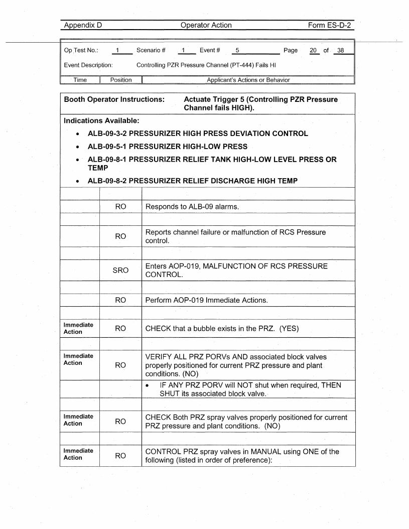
Op .Test No.: 1 Scenario # 1 Event # 5 Page 20 of· 38-Event Description: Controlling PZR Pressure Channel (PT-444) Fails HI
I . Time II Position II Applicant's Actions or Behavior I
Booth Operator Instructions: Actuate Trigger 5 (Controlling PZR PressureChannel fails HIGH).
Indications Available:
• ALB-09-3·2 PRESSURIZER HIGH PRESS DEVI·ATION CONTROL
• ALB-09-5-1 PRESSURIZER HIGH-LOW PRESS
• ALB-09-8-1 PRESSURIZER RELIEF TANK HIGH-LOW LEVE·L PRESS ORTEMP
• ALB-09-8-2 PRESSURIZER RELIEF DISCHARGE HIGH TEMP
RO Responds to ALB-09 alarms.
ROReports channel failure or malfunction of RCS Pressurecontrol.
SROEnters AOP-019., MALFUNCTION OF RCS PRESSURECONTROL.
RO Perform AOP-019 Immediate Actions.
Immediate RO CHECK that a bubble exists in the PRZ. (YES). Action
Immediate VERIFY ALL PRZ PORVs AND associated block valvesAction RO properly positioned for current PRZ pressure and plant.
conditions. (NO)
• IF ANY PRZ PORV will NOT shut when required, THENSHUT its associated block valve.
ImmediateRO
CHECK Both PRZ spray valves properly positioned forcurrentAction PRZ pressure and plant conditions. (NO)
ImmediateRO
CONTROL PRZ spray valves in MANUAL using ONE of theAction following (listed in order of preference):
Appendix D Operator Action Form ES-D-2
Op Test No.:
Event Description:
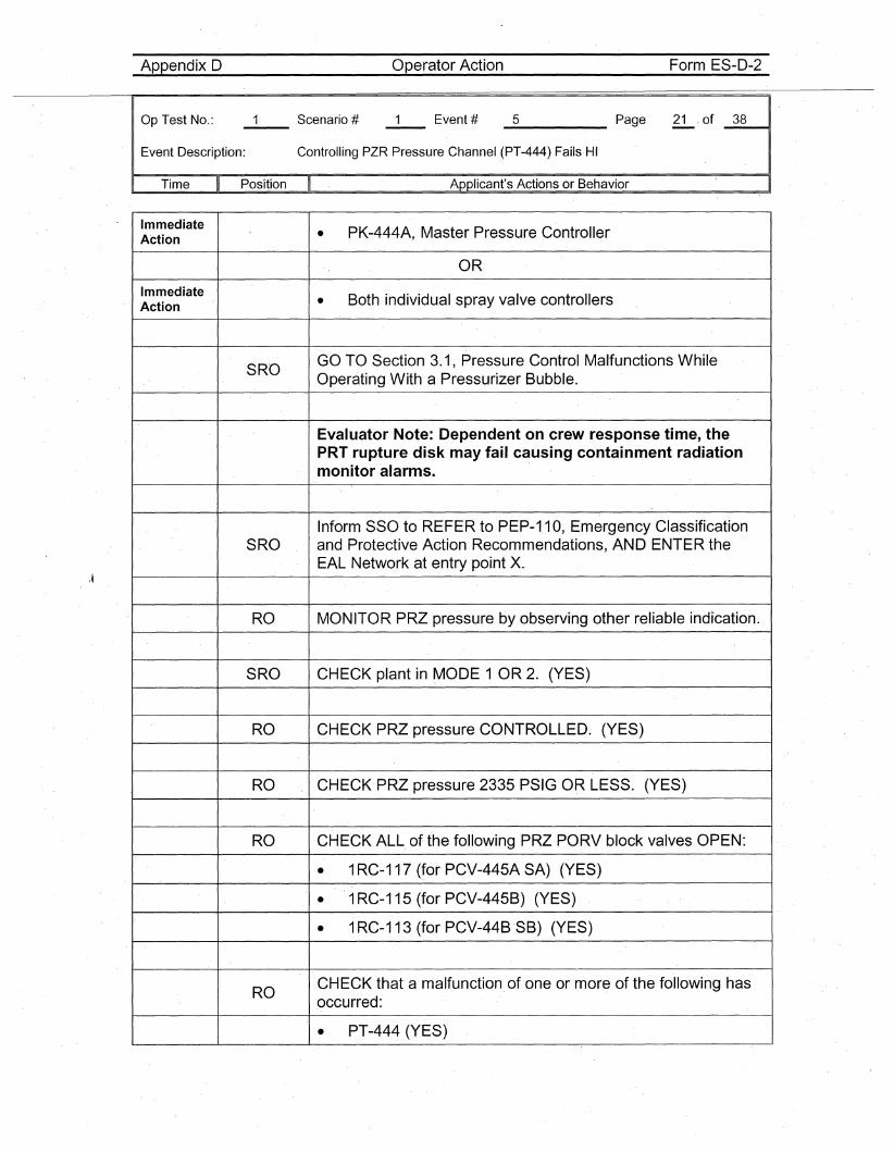
_5 Page 21. of _3_8----11
Controlling PZR Pressure Channel (PT-444) Fails HI
Time Position Applicant's Actions or Behavior
ImmediatePK-444A, Master Pressure ControllerAction •
OR.
Immediate Both individual spray valve controllersAction •
SROGO TO Section 3.1, Pressure Control Malfunctions WhileOperating With a Pressurizer Bubble.
Evaluator Note: Dependent on crew response time, thePRT rupture disk may fail causing containment radiationmonitor alarms.
Inform SSO to REFER to PEP-1.10, Emergency ClassificationSRO and Protective Action Recommendations, AND ENTER the
EAL Network at entry poi.nt x.
RO MONITOR PRZ pressure by observing other reliable indication.
SRO CHECK plant in MODE 1 OR 2. (YES)
RO CHECK PRZ pressure CONTROLLED. (YES)
RO CHECK·PRZ pressure 2335 PSIG OR LESS. (YES)
RO CHECK ALL of the following PRZ PORV block valves OPEN:
• 1R'C-117 (for PCV-445A SA) (YES)
• 1RC-115 (for PCV-445B) (YES)
• 1RC-113 (for PCV-44B 'SB) (YES)
ROCHECK that a malfunction of one or more of the following hasoccurred:
• PT-444 (YES)
Appendix D Operator Action Form ES-D-2
Op.Test No.:
Event Description:
. Time 'II Position
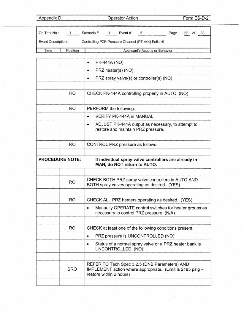
_5 Page 22 of. ·_3_8----11
Controlling PZR Pressure Channel (PT-444) Fails HI
Applicant's Actions or Behavior
• PK-444A (NO)
• PRZ heater(s) (NO)
• PRZ spray valve(s) or controller(s) (NO)
RO CHECK PK-444A controlling properly in AUTO. (NO)
RO PERFORM the following:
• VERIFY PK-444A in MANUAL.
• ADJUST PK-444A output as necessary, to attempt torestore and maintain PRZ pressure.
RO CONTROL PRZ pressure as follows:
PROCEDURE NOTE: If individual spray valve controllers are already in 'MAN, do NOT return to AUTO.
ROCHECK BOTH PRZ spray valve controllers in AUTO .ANDBOTH spray valves operating as desired. (YES)
RO CHECK ALL PRZ heaters operating as desired. (YES)
• Manually OPERATE control switches for heater groups asnecessary to control PRZ pressure. (N/A)
RO CHECK at least one of the following conditions present:
• PRZ pressure is UNCONTROLLED (NO)·
• Status of a normal spray valve' .or a PRZ heater bank isUNCONTROLLED (NO)
REFER TO Tech Spec 3.2.5 (DNBParameters) ANDSRO IMPLEMENT action where appropriate. (Limit is 2185 psig-
restore within 2 hours)
Appendix D Operator Actio-n Form ES-D-2
Op Test No.:
Event Description:
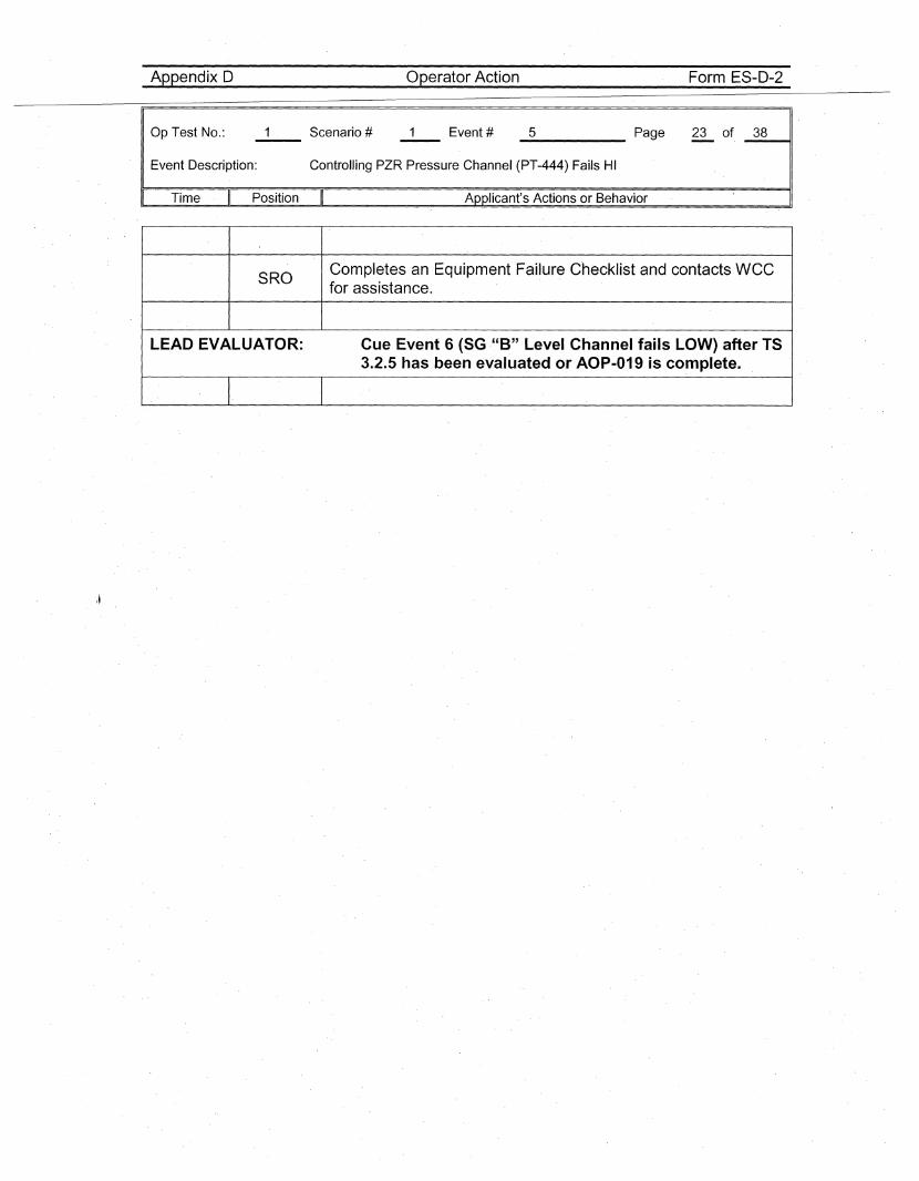
_5 Page 23 of _3_8_-.ol'
Controlling PZR Pressure Channel (PT-444) Fails HI
Time Position Applicant's Actions or Behavior
SROCompletes an Equipment Failure Checklist and contactsWCCfor assistance.
LEAD EVALUATOR: Cue Event 6 (SG -"B" Level Channel fails LOW) after TS3.2.5 has been evaluated or AOP-019 is complete.
Appendix D
Op Test No.:
operator Action
All Event #
Form ES-O-2
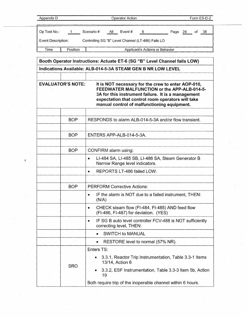
_6 Page 24 of _3_8---11
Event Description: Controlling SG "B" Level Channel (LT-486) Fails LO
Time .Position Applicant's Actions or Behavior
Booth Operator Instructions: Actuate ET"6 (SG "B" Level Channel fails LOW)
Indications Available: ALB-014-5-3A STEAM GEN B NR LOW LEVEL
EVALUATOR'S NOTE: It is NOT necessary for the crew to enter AOp·-01 0,FEEDWATER MALFUNCTION or the APP-ALB-014-5-3A for this instrument failure. It is a managementexpectation that control room operators will takemanual control of malfunctioning equipment.
BOP RESPONDS to alarm ALB-014-5-3A arid/or flow transient.
BOP ENTERS APP-ALB-014-5-3A.
BOP CONFIRM alarm using:
• LI-484 SA, LI-485 SB, LI-486 SA, Steam Generator. BNarrow Range level indicators.
• REPORTS LT-486 failed LOW.
BOP PERFORM Corrective Actions:
• IF the alarm is NOT due to a failed instrument, TH·EN:(N/A)
• CHECK steam flow (FI~484, FI-485) AND feed flow(FI-486, FI-487) for deviation. (YES)
• IF SG B auto level controller FCV-488 is NOT sufficientlycorrecting level, THEN:
• SWITCH to MANUAL
• RESTORE ·Ievel to normal (57°/0 NR).
Enters TS:
• 3.3.1, Reactor Trip Instrumentation, Table 3.3-1 Items
SRO13/14, Action 6
• 3.3.2, ESF Instrumentation, Table 3.3-3 Item 5b, Action19
Both require trip of the inoperable cHannel within 6 hours.
Appendix D
Op Test No.: Scenario #--
operator Action
All Event # _6 Page 25
Form ES-D-2
of 38
Event Description: Controlling SG "B" Level Channel (LT-486) Fails LO
. Time Position Applicant's Actions or Behavior
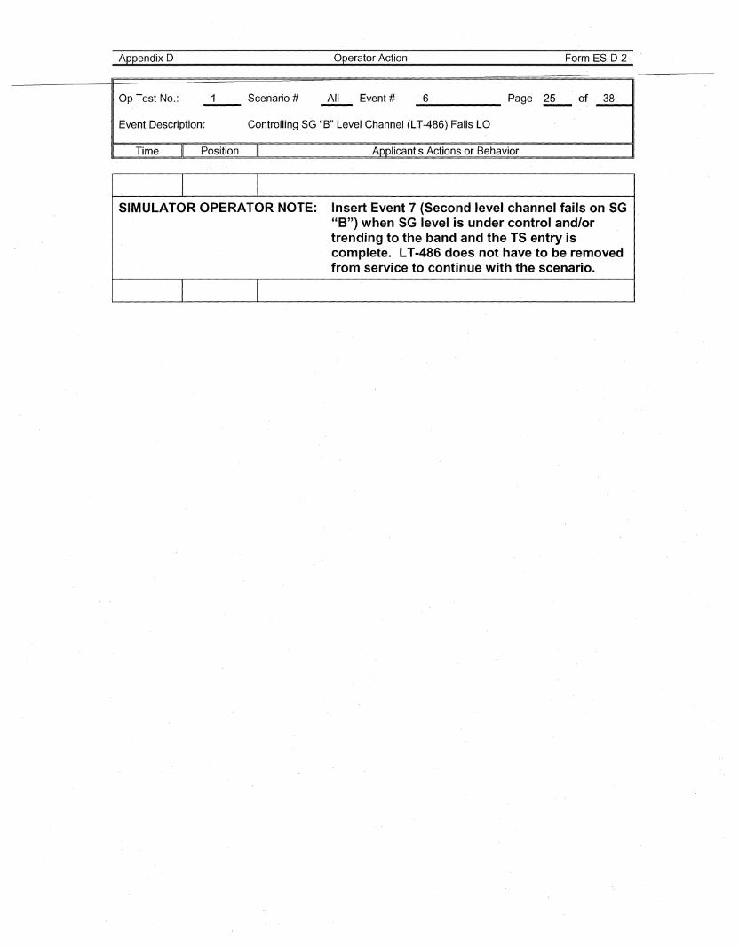
I ISIMULATOR OPERATOR NOTE: Insert Event 7 (Second level channel fails on SG
"8") when SG level is under control and/ortrending to the band and the TS entry iscomplete. LT.;.486 does not have to be removedfrom service to continue with the scenario.
I I
Appendix D operator Action Form ES-D-2
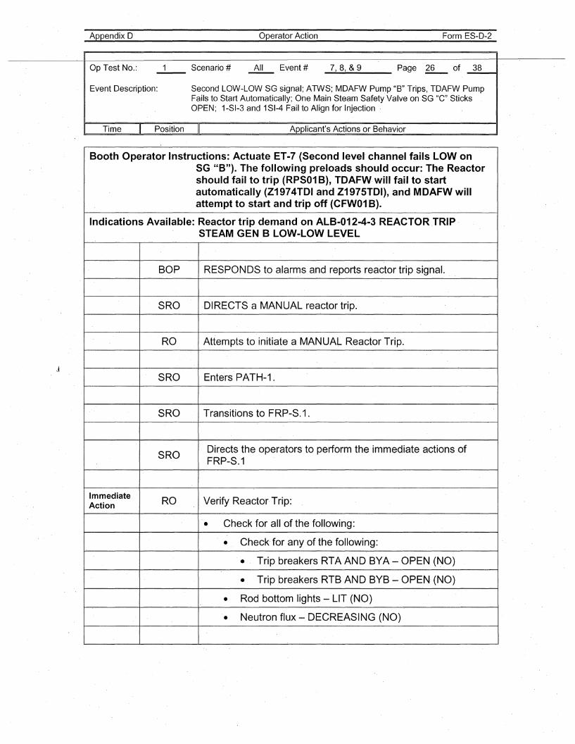
Op Test No.: 1 Scenario # All Event # 7,8, &9 Page 26 of 38--Event Description: Second LOW-LOW SG signal; ATWS; MDAFW Pump "B" Trips, TDAFW Pump
Fails to Start Automatically; One Main Steam Safety Valve on SG "C"SticksOPEN; 1-SI-3 and 1SI-4 Fail to Align for Injection
·1 Time II Position II Applicant's Actions or Behavior I
Booth Operator Instructions: Actuate ET-7 (Second level channel fails LOW onSG "8").. The following preloads should occur: The Reactorshould fail to trip (RPS01 B), TDAFW will fail to startautomatically (Z1974TDI and Z1975TDI), and· MDAFW willattempt to start and trip off (CFyv01 B).
Indications Available: Reactor trip demand on ALB-012-4-3 REACTOR.TRIPSTEAM GEN B LOW-LOW LEVEL
BOP RESPONDS to alarms and reports reactor trip signal.
SRO DIRECTS a MANUAL reactor trip.
RO Attempts to initiate a MANUAL Reactor Trip.
SRO Enters PATH-1.
SRO Transitions to FRP-S.. 1.
SRODirects the operators to perform the immediate actions ofFRP-S.1
ImmediateRO Verify Reactor Trip:Action
• Check for all of the following:
• Check' for any of the following:
• Trip breakers RTA AND BYA - OPEN (NO)
• Trip breakers RTB AND BYB - OPEN· (NO)
• Rod bottom lights - LIT (NO)
• Neutron flux - DECREASING (NO)
Appendix D
Op Test No.:
operator Action
All Event #
Form ES-D-2
_7--.,_8-..,&_9 Page ~ of. _3_811
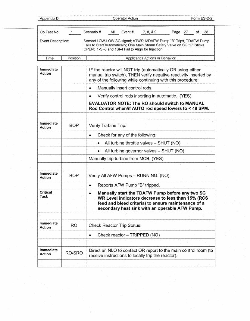
Event Description: Second LOW~LOW SG signal; ATWS; MDAFW Pump "B" Trips, TDAFW PumpFails to Start·Automatically; One Main Steam Safety Valve on SG "C" SticksOPEN; 1-SI-3 and 1SI-4 Fail to Align for Injection
Time Position Applicant's Actions or Behavior
Immediate IF the reactor will NOT trip (automatically OR using eitherAction manual trip switch), THEN verify negative reactivity.inserted by
any of the following while continuing with this procedure:
• Manually insert control rods.
• Verify control rods inserting in automatic. (YES)
EVALUATOR NOTE: The RO should switch to MANUALRod Control.when/if AUTO rod speed lowers to < 48 SPM.
Immediate BOP Verify Turbine Trip:Action
• Check for any of the following:
• All turbine throttle v~lves - SHUT (NO)
• All turbine governor valves - SHUT (NO)
Manually trip turbine from MCB. (YES)
ImmediateBOP Verify All AFW Pumps - RUNNING. (NO)Action
• Reports AFW Pump "B" tripped.
Critical • Manually start the TDAFW Pump before any two SGTask .WR Level ind.icators decrease to less than 150/0 (RCS
feed and bleed criteria). to ensure maintenance of asecondary heat sink with an operable AFW Pump.
Immediate RO Check Reactor Trip Status:Action
• Check react<;>r - TRIPPED (NO)
Immediate Direct an NLO to contact OR report·to the main control room (toAction RO/SRO
receive instructions to locally trip the reactor).
Appendix D
Op Test No.: Scenario #--
Operator Action
All Event #
Form ES-D-2
_7--.,_8...., &_9 Page ~ of _3_H~,
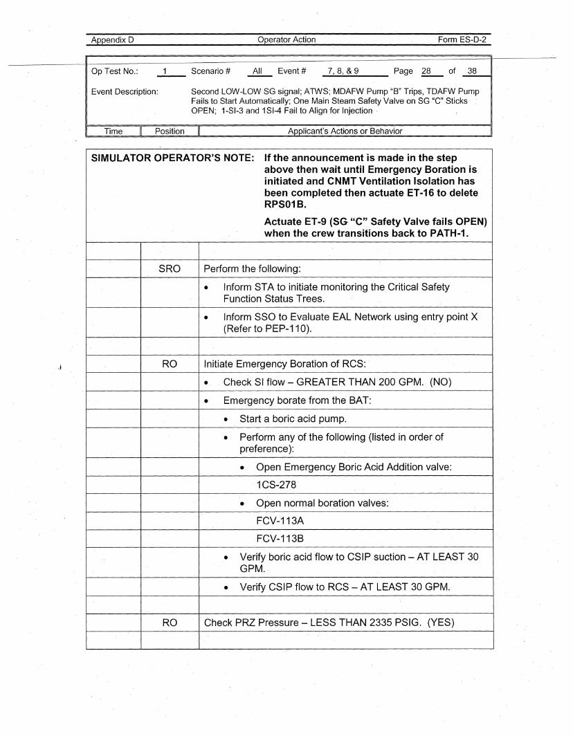
Event Description: Second LOW-LOW SG signal; ATWS; MDAFW Pump "B" Trips, TDAFW PumpFails to Start Automatically; One Main Steam Safety Valve on SG "C"SticksOPEN; 1-SI-3 and 1SI-4 Fail to Align for Injection,
Time Position Applicant's Actions or Behavior
\~
SIMULATOR OPERATOR'S NOTE: If the announcement is made in the stepabove then wait until Emergency Boration isinitiated and CNMT Ventilation Isolation hasbeen completed then actuate ,ET-16 to deleteRPS01B.
Actuate ET-9 (SG· "e" Safety Valve fails, OPEN)when the crew transitions back to PATH-1.
SRO Perform the following,:
• Inform STA to initiate monitoring the Critical SafetyFunction Status Trees.
• Inform SSO to Evaluate EAL Network using entry point X(Refer to PEP-110).
RO Initiate Emergency Boration of RCS:
• Check SI flow - GREATER THAN 200 GPM. (NO)
• Emergency borate from the BAT:
• Start a boric acid pump.
• Perform 'any 'of the following (listed in order ofpreference):
• Open, Emergency Boric Acid Addition valve:
, 1CS-278
• Open normal boration valves:
FCV-113A
FCV-113B
• Verify boric acid flow to CSIP suction - AT LEAST 30GPM.,
• Verify CSIP flow to RCS -AT LEAST30,GPM.'
RO CheckPRZ Pressure'- LESS THAN 2335 PSIG. (YES)
Appendix 0
Op Test No.:
Operator Action
All Event #
Form ES-D-2
_7..-,_8--.,&_9___ Page '~ of _3_8---t1
Event Description: Second LOW~LOW SG signal; ATWS; MDAFW Pump "B" Trips, TDAFW Pump'Fails to Start Automatically; One Main Steam Safety Valve on SG "C" SticksOPEN; 1-SI-3 and 1SI-4 Fail to Align for Injection
Time Position Applicant's Actions or Behavior
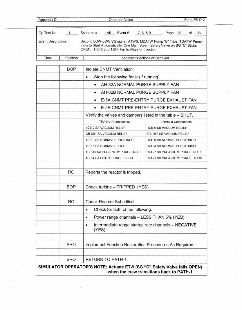
BOP Isolate CNMT Ventilation:
• Stop the following fans: (If running)
• AH-82A NORMAL 'PURGE SUPPLY FAN
• AH-82B NORMAL PURGE SUPPLY FAN
• E-5A CNMT PRE-ENTRY PURGE EXHAUST FAN
• E-5B CNMT PRE-ENTRY PURGE EXHAUST FAN
Verify the valves and dampers listed in the table - SHUT.
TRAIN A Components TRAIN B Components
1CB-2 SA VACUUM RELIEF 1CB-6 SB VACUUM RELIEF
CB-D51 SA VACUUM RELIEF CB-052 SB VACUUM RELIEF
1CP-9 SA NORMAL PURGE INLET 1CP-6 SB NORMAL ·PURGE INLET
1CP-5 SA NORMAL PURGE 1CP-3 SB NORMAL PURGE DISCH
1CP-10 SA PRE-ENTRY PURGE INLET 1CP-7 SB PRE-ENTRY PURGE INLET
1CP-4 SA ENTRY PURGE DISCH 1CP-1 SB PRE-ENTRY PURGE DisCH
RO Reports the reactor is tripped.
BOP Check tu'rbine - TRIPPED (YES)
RO C,heck Reactor Subcritical:
• Check for both of the following:
• Power range channels - LESS THAN 5% (YES)
• Intermediate range startup rate channels- NEGATIVE(YES)
SRO Implement Function Restoration Procedures As Required.
SRO RETURN TO PATH-1.
SIMULATOR OPERATOR'S NOTE: Actuate ET-9(SG "C" Safety Valve fails OPEN)when the crew transitions back to PATH-1.
Appendix 0
Op Test No.:
Operator Action
All Event #
Form ES-D-2
_7--.,_8__, &_9 Page -l2.- of__3_8---41
Event Description: Second LOW~LOW SG signal; ATWS; MDAFW Pump "B" Trips, TDAFW PumpFails to Start Automatically; -One Main Steam Safety Valve onSG "e" SticksOPEN; 1-SI-3 and 1SI-4 Fail to Align for Injection
Time Position Applicant's Actions or Behavior
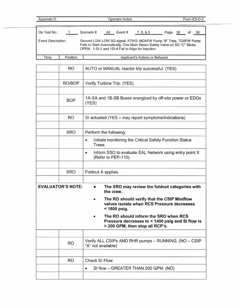
RO AUTO or MANUAL reactor trip successful. (YES)
RO/BOP Verify Turbine Trip. (YES) -
BOP1A-SA and 1B-SB Buses energized by off~site power or EDGs(YES)
RO SI actuated (YES - may report symptoms/indications)
SRO Perform th-e following:
.- Initiate monitoring the Critical Safety Function StatusTrees._
• Inform SSO to evaluate EAL Network using entry point X(Refer to PEP-11 0). '
SRO Foldout A applies.
EVALUATOR'S NOTE: • The SRO may review the foldout categories withthe crew.
• The RO should verify that the CSIP Miniflowvalves isolate when RCS Pressure decreases< 1800 psig.
• The RO should inform-the SRO when RCSPressure decreases to < 1400 psig and 51 flow is> 200 GPM, then stop all RCP's.
ROVerify ALL CSIPs AND RHR pumps - RUNNING. (NO - CSIP"A" not available)
RO Check SI Flow:
• SI flow- GREATER THAN 200 GPM. (NO)
Appendix 0
Op Test No.: Scenario #--
operator Action
All Event #
Form ES-D-2
_7__,_8...., &_9 Page ll- of _3_8__u
Event Description: Second LOW-LOW SG signal; ATWS; MDAFW Pump "B" Trips, TDAFW PumpFails to Start Automatically; One Main Steam Safety Valve on SG "e" SticksOPEN; 1-SI-3 and 1SI-4 Fail to Align for Injection
Time Position Applicant's Actions or Behavior
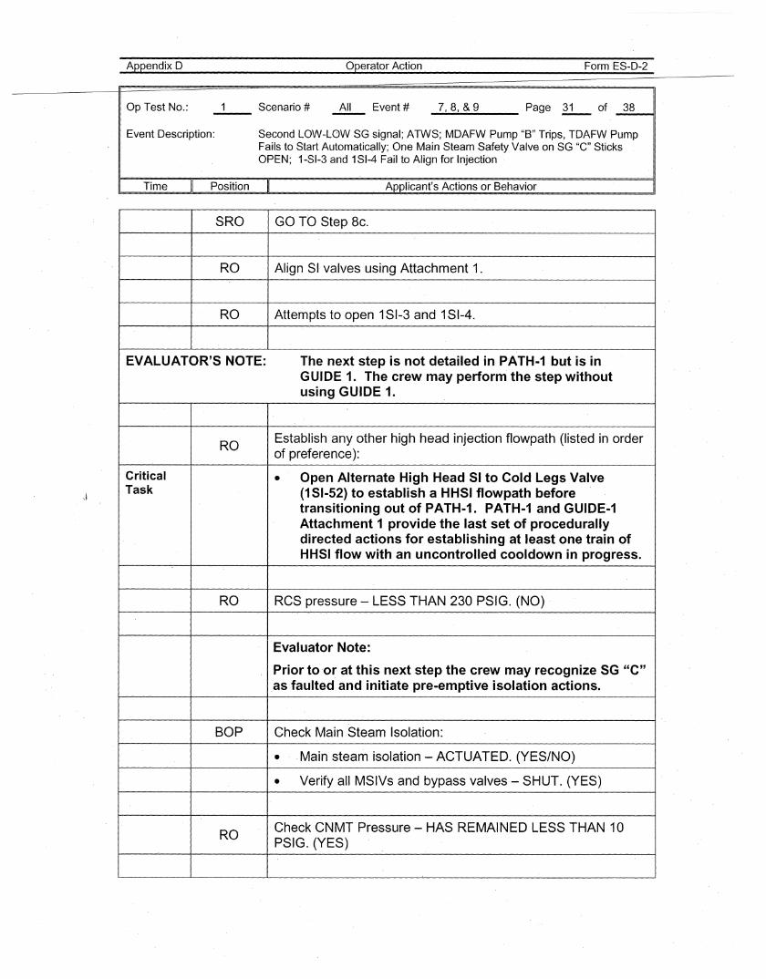
SRO GO TO Step Bc.
RO Align SI valves using Attachment 1.
RO Attempts to open 1SI-3 and 1SI-4.
EVALUATOR'S NOTE: The next step is not detailed in PATH-1 but is inGUIDE 1. The crew may perform the step withoutusing GUIDE 1.
ROEstablish any other high head injection fl.owpath (listed in orderof preference):
Critical • Open Alternate High Head SI to Cold Legs ValveTask (151-52) to establish a HHSI flowpath before
transitioning out of PATH-1. PATH-1 and GUIDE-1Attachment 1 provide the last set of procedurallydirected actions for establishing at least one train ofHHSI flow with an uncontrolled cooldown in progress.
RO RCS pressure - LESS THAN 230 PSIG. (NO)
Evaluator Note:
Prior to 'o~ at this next step the crew may recognize SG "C".as faulted and initiate pre-emptive isolation actions.
BOP Check Main Steam Isolation:
• Main steam isolation - ACTUATED. (YES/NO)
• Verify all MSIVs and bypass valves- SHUT. (YES)
ROCheck CNMT Pressure - HAS REMAINED LESS THAN 10PSIG. (YES)
Appendix 0
Op Test No.:
Operator Action
All Event #
Form ES-D-2
_7-.,_8....., &_9 Page ~ of. _3_841
Event Description: Second LOW~LOW SG signal; ATWS; MDAFW Pump "B" Trips, TDAFW PumpFails to Start'Automatically;One Main Steam Safety Valve on SG "e" SticksOPEN; 1-SI-3 and 1SI-4 Fail to Align for Injection
Time Position Applicant's Actions or Behavior
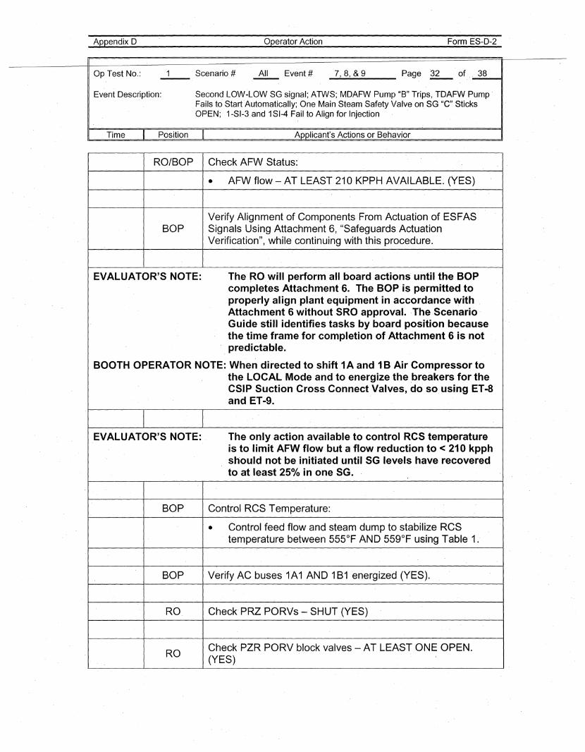
RO/BOP Check AFW Status:
• AFW flow - AT LEAST 210 KP·PH AVAILABLE. (YES)
Verify Alignment of Components From Actuation of ESFASBOP Signals Using Attachment 6, "Safeguards Actuation
Verification", while continuing with this procedure.
EVALUATOR'S NOTE: The RO .will perform all board actions until the BOPcompletes Attachment·6. The BOP is permitted toproperly align .plant equipment in accordance withAttachment 6 without SRO approval. ·The Scenario'Guide still identifies tasks by board position becau.sethe time frame for completion of Attachment 6 is notpredictable.
BOOTH OPERATOR NOTE: When directed to shift1A and 1B Air Compressor tothe LOCAL Mode and to energize the .breakers for theCS.IP Suction Cross Connect Valves, do so using ET-8and ET-9.
EVALUATOR'S NOT·E: The only action available to control RCS temperatureis to' limit AFW flow but a flow reduction to < 210 kpphshould not be initiated until SG levels have recoveredto at least 250/0 in one SG.
BOP Control RCS Temperature:
• Control feed flow and steam dump to stabilize ReStemperature between 555°F AND 559°F using Table 1.
BOP Verify.AC buses1A1 AND 1B1 energized (YES).
RO Check' PRZ PORVs - SHUT (YES)
ROCheck PZR PORV block valves - AT LEAST ONE OPEN.(YES)
Appendix D' operator Action Form ES-D-2
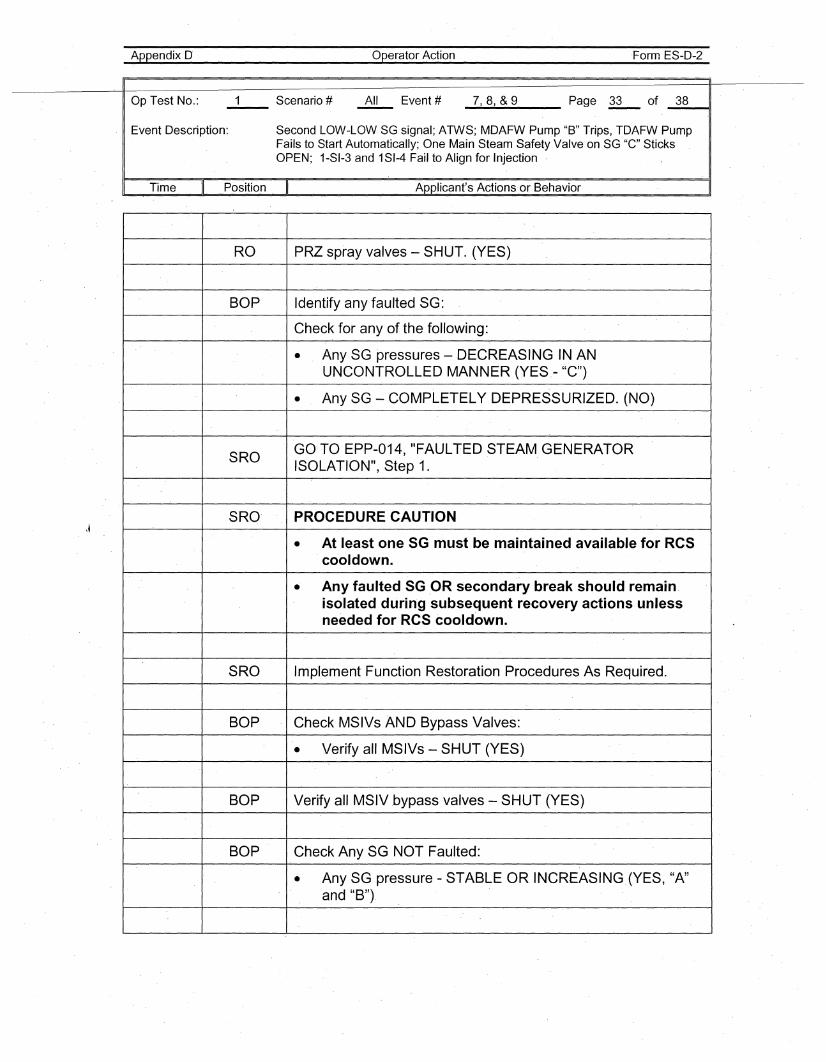
Op Test No.: 1 Scenario # All Event # 7,8, &9 Page 33 of 38--
Event Description: Second LOW-LOW SG signal; ATWS; MDAFW Pump "B" Trips, TDAFW PumpFails to Start Automatically; One Main Steam Safety Valve on SG "e" SticksOPEN; 1-SI-3 and 1SI-4 Fail to Align for Injection
Time II Position II Applicant's Actions·or Behavior I
RO PRZ spray valves -- SHUT. (YES)
BOP Identify any faulted SG:
Check for any of the following:
• Any SG pressures - DECREASING IN ANUNCONTROLLED MANNER (YES.- "C")
• Any SG - COMPLETELY DEPRESSURIZED. (NO)
SROGO·TO EPP-014, "FAULTED STEAM GENERATORISOLATION", Step 1.
SRO' PROCEDURE CAUTION
• At least one SG must be maintained available for RCScooldown.
• Any faulted SG .OR secondary break should remain.isolated during subsequent recovery actions unlessneeded for RCS cooldown.
SRO Implement Function Restoratio'n Procedures As Required.
BOP Check MSIVs AND Bypass Valves:
• Verify all MSIVs - SHUT (YES)
BOP Verify all MSIVbypass valves - SHUT (YES)
BOP Check Any SG NOT Faulted:
• Any SG pressure - STABLE OR INCR·EASING (YES, "A"and "B")
Appendix D operator Action Form ES-D-2
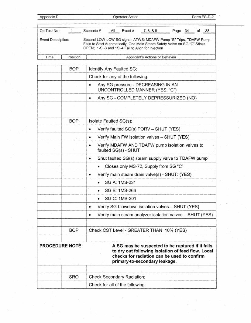
Op Test No.: 1 Scenario # All' Event # 7,8, &9 Page 34 of 38--
Event Description: Second LOW-LOW SG signal; ATWS; MDAFW Pump "B" Trips, TDAFW PumpFails to' Start Automatically; One Main Steam Safety Valve onSG "e" SticksOPEN; 1-SI-3 and 1SI-4 Fail to Align for Injection
I Time
"
Position II Applicant's Actions or Behavior I
BOP Identify Any Faulted SG:
Check for any of the'following:
• Any SG pressure - DEeRE'ASING IN ANUNCONTROLLED MANNER (YES, "C")
• Any SG - COMPLETELY DEPRESSURIZED (NO)
BOP Isolate Faulted SG(s):
• Verify faulted SG(s) PORV - SHUT (YES)
• Verify Main FW isolation valves -- SHUT (YES)
• Verify MDAFW AND TDA'FW pump isolation valves tofaultedSG(s)- SHUT
• Shut faulted SG(s) steam supply valve toTDAFW pum,p
• ,Closes only MS-72, Supply from SG '"C"
• Verify main steam drain valve(s) - SHUT: (YES) ,
• SG A: 1MS-23'1
• SG B: 1MS-266
• SG C: 1MS-301
• Verify SG blowdown' isolation valves - SHUT (YES)
• Verify main steam analyzer isolation valves - SHUT (YES)
BOP Check CST Level - GREATER THAN 10% (YES)
PROCEDURE NOTE: A SG may be suspected to be ruptured if it failsto dry out following isolation of feed flow. Localchecks for radiation can be used to confirmprimary-to-secondary leakage.
SRO Check Secondary Radiation:
Check for all of the following:
Appendix D
Op Test No.:
operator Action
All Event #
Form ES-D-2
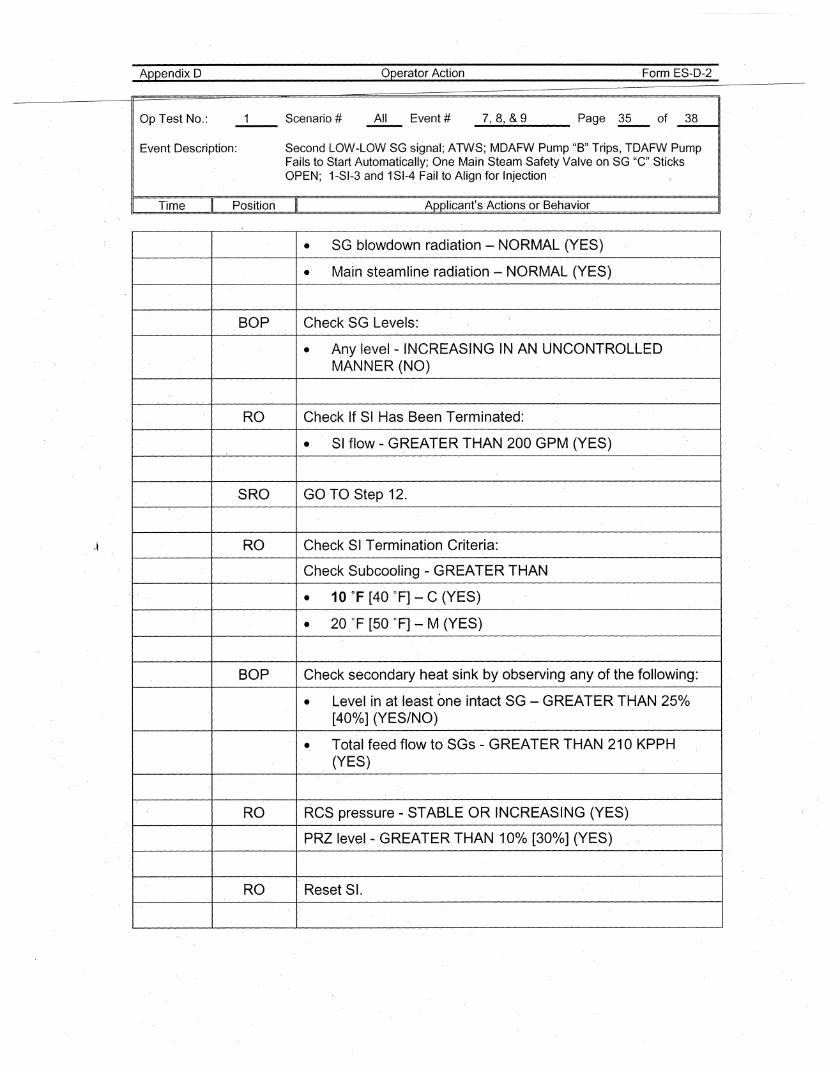
_7__,_8--.,&_9 Page ~ of _3_8u
Event Description: Second LOW-LOW SG signal; ATWS; MDAFW Pump "B" Trips, TDAFW PumpFails to Start Automatically; One Main Steam Safety Valve on SG "C"SticksOPEN; 1-SI-3 and 1SI-4 Fail to Align for Injection
Time Position Applicant's Actions or Behavior
• SG blowdown radiation - NORM·AL (YES)
• Main steamline radiation - NORMAL (YES)
BOP Check SG Levels:
• Any level - INCREASING IN AN UNCONTROLLEDMANNER (NO)
RO Check If SI Has Been Terminated:
• SI flow - GREATER THAN 200 GPM (YES)
SRO GO TO Step 12.
RD' CheckSI Termination Criteria:
Check Subcooling - GREATER THAN
• 10 of [40 OF] ~ C (YES)
• 20 of [50 OF] ~M (YES)
BOP Check secondary heat sink by observing any of the following:'
• Level in at least one intact SG - GREATER THAN 25%[400/0] (YES/NO)
• Total feed flow to SGs - GREATER THAN 210 KPPH(YES)
RO RCS pressure - STABLE OR INCREAS·ING (YES)
PRZ level- GREATER THAN 10% [30%] (YES)
RO Reset SI.
Appendix D
Op Test No.: Scenario #--
operator Action
All Event #
Form ES-D-2
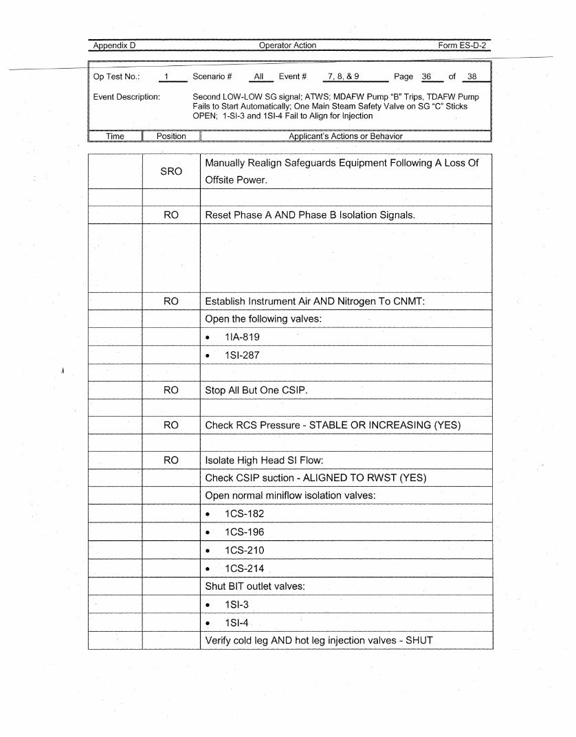
_7__,_8...., &_9___ Page ~ of _3_8~,
Event Description: Second LOW-LOW SG signal; ATWS; MDAFW Pump "B" Trips, TDAFW PumpFails to Start Automatically; One Main Steam Safety Valve on SG "C"'SticksOPEN; 1-SI-3 and 1SI-4 Fail to Align for Injection
Time Position Applicant's Actions or Behavior
\~
SROManually Realign Safeguards Equipment Following A Loss Of
Offsite Power.
RO Reset Phase A AND Phase B Isolation Signals.
RO Establish Instru,ment Air AND Nitrogen To CNMT:
Open the following valves:
• 11A-819
• 1SI-287
RO Stop All But·One CSIP.
RO 'CheckRCS Pressure - STABLE OR INCREASING (YES)
RO Isolate High Head SI Flow:
Check CSIP suction - ALIGNED TO RWST (YES)
Open normal miniflow isolation valves:
• 1CS-182
• 1CS-196
• 1CS-210
• . '1C,S-214
Shut BIT outlet valves:
• 1SI-3
• 1SI-4
.Verify cold leg AND hot leg injection valves - SHUT
Appendix D
Op Test No.: Scenario #--
Operator Action
All Event #
Form ES-D-2
_7..-,_8...., &_9 Page oR- of _3_8__11
Event Description: Second LOW-LOW SG signal; ATWS; MDAFW Pump "B" Trips, TDAFW PumpFails to StarfAutomatically;One Main Steam Safety Valve on SG "C" SticksOPEN; 1-SI-3 and 1SI-4 Fail to Align for Injection
Time Position Applicant's Actions or Behavior
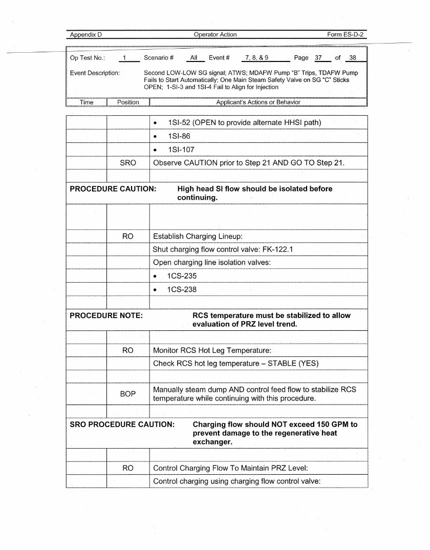
• 1SI-52 (OPEN to provide alternate HHSI path)
• 1SI-86
• 181-107
SRO Observe CAUTION prior to Step 21 AND GO TO Step 21.
PROCEDURE CAUTION: High head 51 flow should be isolated beforecontinuing.
RO Establish Charging Lineup:
Sohut charging flow control valve: FK-122.1
Open charging line isolation valves:
• 1CS-235
• 1CS-238
PROCEDURE NOTE: RCS temperature must be stabilized to allowevaluation of PRZ level trend.
RO Monitor RCSHot Leg Temperature:
Check RCS hot leg temperature -STABLE (YES)
BOPManually steam dump AND control feed flow to stabilize RCStemperature while continuing with this procedure.
SRO PROCEDURE CAUTION: Charging flow should NOT exceed 150 GPM toprevent damage to the-regenerative"heatexchanger.
RO Control Charging Flow To Maintain PRZ Level:
Control charging using charging flow control valve:
Appendix D
Op Test No.: Scenario #--
operator Action
All Event #
Form ES-D-2
----.7,_8....., _&_9 Page ~ of _3_8_-41
Event Description:
Time - II Position
Second LOW-LOW SG signal; ATWS; MDAFW Pump "B" Trips, TDAFW PumpFails to Start Automatically; One Main Steam Safety Valve on SG "C"SticksOPEN; 1-SI-3 and 1SI-4Fail to Align for Injection
Applicant's Actions or Behavior
\~
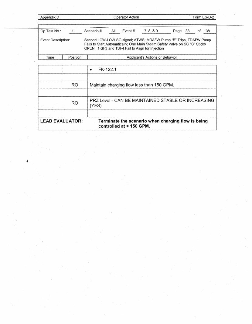
• FK-122.1
RO Maintain charging flow less than 150 GPM.
ROPRZ Level - CAN BE MAINTAINED STABLE· OR rNCREASING(YES)
LEAD EVALUATOR: Terminate the scenario when charging flow is beingcontrolled at < 150 GPM.
Appendix D'
Facility:
Examiners:
SHEARON-HARRIS
Scenario Outline
Scenario No.:
Operators:
2 Op Test N.o.:
Form ES-D-1
2007· NRC
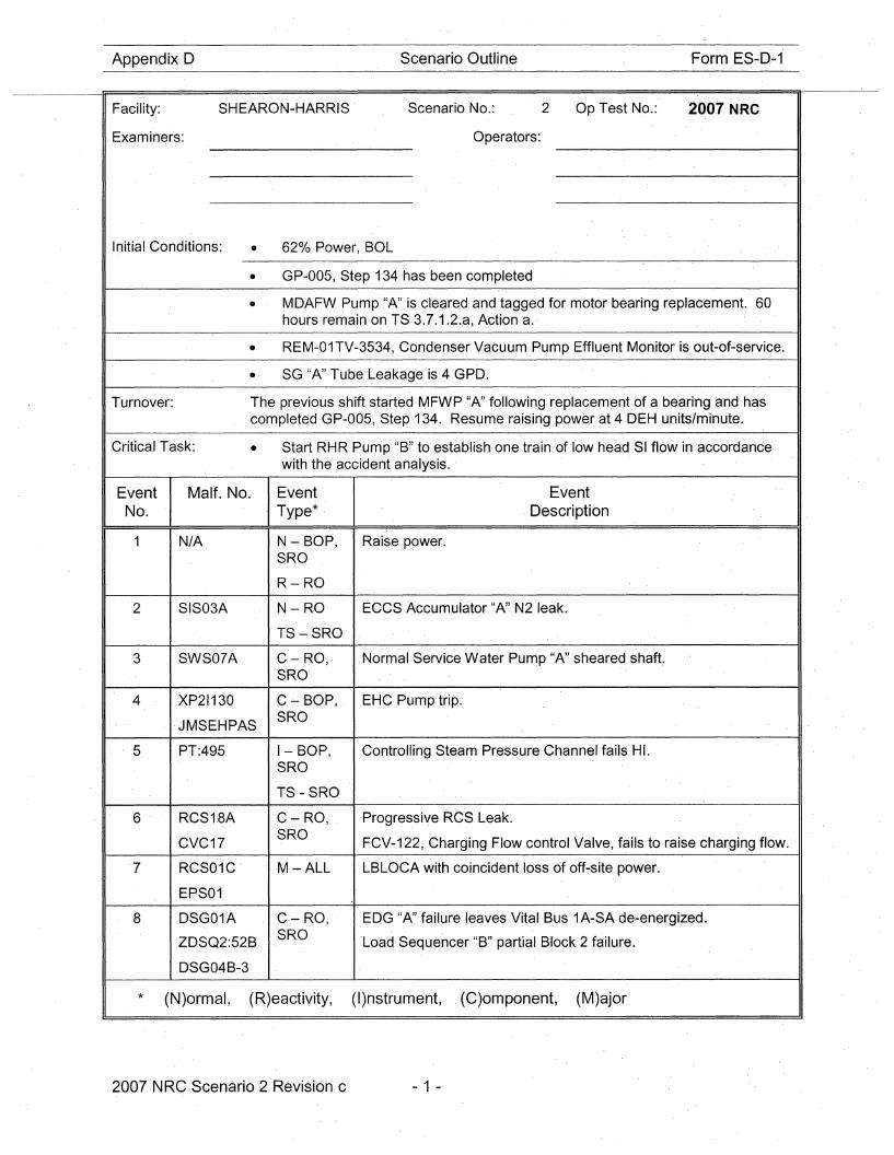
Initial Conditions: • 620/0 Power, BOL
• GP-005, Step 134 has been completed
• MDAFW Pump "A" is cleared and tagged for motor bearing replacement. 60hours remain on TS 3.7.1.2.a, Action a.
• REM-01TV-3534, Condenser Vacuum Pump Effluent Monitor is out-of-service.
• SG "A" Tube Leakage is 4 GPD.
Turnover:
Critical Task:
The previous shift started MFWP "A" following replacement of a bearing and hascompleted GP-005, Step 134. Resume raising .power at 4 DEH units/minute.
• Start RHR Pump "B" to establish one train of low head SI flow in accordancewith the accident analysis..
EventNo.
Malt. No.
N/A
EventType*
N - BOP,SRO
R-·RO
Event.Description
Raise power.
2 SIS03A
3 SWS07A
4 XP21130
·JMSEHPAS
5 PT:495
6 RCS18A
CVC17
7 RCS01C
EPS01
8 DSG01A
ZDSQ2:52B
DSG04B-3
N-RO
TS-SRO
C-RO,SRO
C~ BOP,SRO
I-BOP,SRO
TS - SRO
C-RO,SRO
M-ALL
C~RO,
SRO
ECCS Accumulator "A" N2 leak.
Normal Service Water Pump "A" sheared shaft.
EHC Pump trip.
Controlling Steam Pressure Channel fails HI.
Progressive RCS Leak.
FCV-122, Charging Flow control Valve, fails to raise 'charging flow.
LBLOCA with coincident loss of off-site power.
EDG "A" failure leaves Vital Bus 1A-SA de-energized.
'Load Sequencer "B" partial Block 2 failure.
* (N)ormal, (R)eactivity, (I)nstrument, (C)omponent, (M)ajor.
2007 NRC Scenario 2 Revision c - 1 -
Scenario .Event Description
Shearon-Harris 2007 NRC Scenario 2
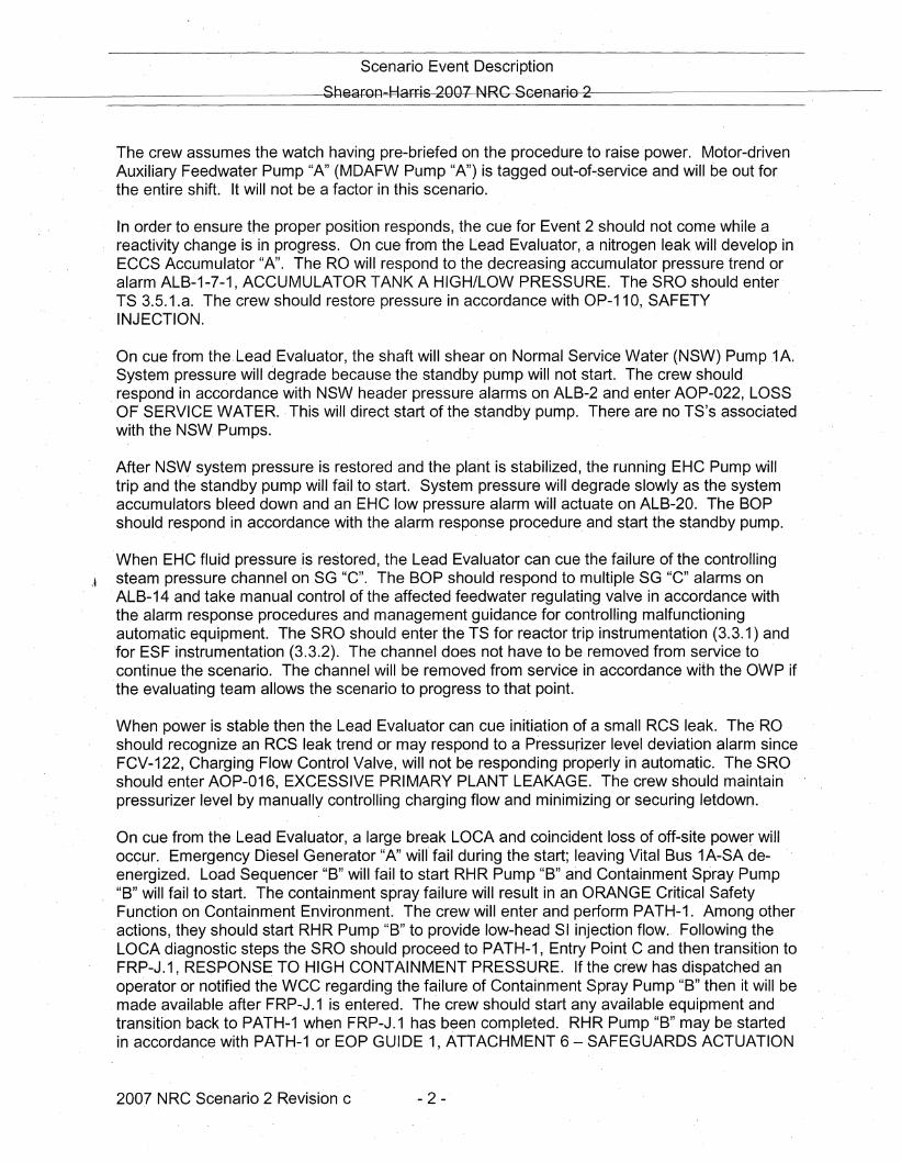
The crew assumes the watch having pre-briefed on the procedure to· raise power. Motor-drivenAuxiliary Feedwater Pump "A" (MDAFW Pump "A") is tagged out-of~service and will b~ out forthe entire shift. It will not be a factor in this scenario.
Ion order to ensure the proper position responds, the cue for Event 2 should not come while areactivity change is in progress. On cue from the Lead Evaluator,.a nitrogen leak will develop inECCS Accumulator "A". The RO will respond to the decreasing accumulator pressure trend oralarm ALB-1-7-1, ACCUMULATOR TANK A HIGH/LOW PRESSURE. The SRO should enterT.S 3.5.1.a. The crew should restore pressure in accordance with OP-11 0,. SAFETYINJECTION.
On cue from the.Lead Evaluator, the shaft will shear on NormalService.Water (NSW) Pump1A.SystE?m pressure will degrade because the standby pump will not start. The crew shouldrespond in accordance with NSW header pressure alarms on ALB-2. and enter AOP-022, LOSSOF SERVICE WATER.. This will direct start of the standby pump. There are no TS's associatedwith the NSW. Pumps.
After NSW system pressure is restored and the plant is stabilized, the running EHC Pump willtrip and the standby pump will fail to start. System pressure will degrade slowly as the systemaccumulators bleed down and an EHC low pressure alarm will actuate on ALB-20. The BOPshould respond in accordance with the alarm response procedure and start the standby pump.
When EH'C fluid pressure is restored, the Lead Evaluator can cue the failure of the controllingJ steam pressure channel on SG "C". The BOP should 'respond to multiple SG "c" alarms on
ALB-14 and take manual control of the affected feedwater regulating valve in accordance withthe alarm response procedures and management guidance for controlling malfunctioningautomatic equipment. The SRO should enter the TS for reactor trip instrumentation (3.3.1) and"for ESF instrumentation (3.3.2). The channel does not have to be removed from service' tocontinue the scenario. The channel.will be removed from service in accordance with the OWP ifthe evaluating team allows the scenario to progress to that point.
When power is stable then the Lead Evaluator can cue initiation of a small RCS leak. The' ROshould recognize an RCS leak trend or may respond to a Pressurizer level deviation alarm sinceFCV-122, Charging Flow Control Valve,.will not be responding properly in automatic. The SRO .should enter AOP-016, EXCESSIVE PRIMARY PLANT LEAKAGE. The crew should maintainpressurizer level by manually controlling charging flow and minimizing or securing letdown.
On cue from the Lead Evaluator, a large break LOCA and coincident loss of off-site power willoccur. Emergency Diesel Generator "A" win fail during the start; leaving Vital Bus 1A-SA deenergized. Load Sequencer "B" will·fail to start RHR Pump "B" arid Containment Spray Pump"B" will fail to start. The containment spray failure will result in an ORANGE Critical SafetyFunction on Containment Environment. The crew will enter and perform PATH-1·. Among otheractions, they should start RHR Pump "B" to provide low-head SI injection flow.. Following theLOCA diagnostic steps the SRO should proceed to PATH-1, Entry Point C and then transition toFRP-J.1, RESPONSE TO HIGH CONTAINMENT PRESSURE. If the crew has dispatched anoperator or notified the wec regarding the failure of Containment Spray Pump "B" then it will bemade available after FRP-J.1 is entered. The crew should start any available equipment andtransition back to PATH-1 when FRP-J.1 has been completed. RHR Pump "B" may be startedin accordance with PATH-10r EOP GUIDE 1, ATTACHMENT 6 - SAFEG'UARDS ACTUATION
2007 NRC Scenario 2 Revision c - 2 -
S·cenario Event Description
Shearon Harris 2007 NRC Scenario 2
VERIFICATION. The crew will continue in PATH-1 to a point where a "loop back" repeats untilthe transition criteria for EPP-10, TRANSFER TO COLD LEG RECIRCULATiON, is met. TheLead Evaluator can terminate the scenario at the first "loop back" or following a crew briefrelative to cold leg recirculation criteria.
2007 NRC Scenario 2 Revision c - 3 -
Scenario .Event Description
Shearon Harris 2007 NRC Scenario 2
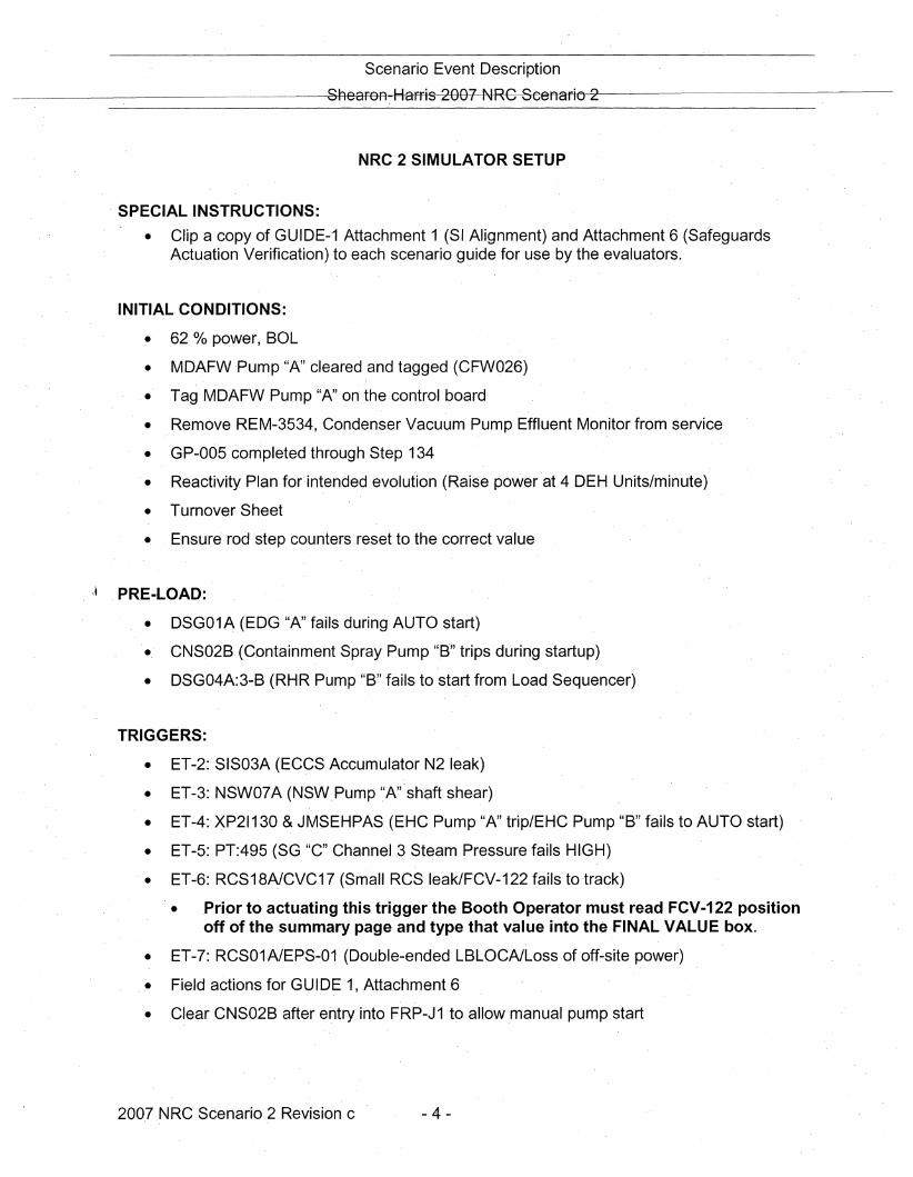
NRC 2 SIMULATOR SETUP
SPECIAL INSTRUCTIONS:
• Clip a copy of GUIDE-1 Attachment 1 (SIAlignment) and Attachment 6 (SafeguardsActuation Verification) to each scenario guide for use by the evaluators.
INITIAL CONDITIONS:
• 62 % power, BOL
• MDAFWPump "A" cleared and tagged (CFW026)
• Tag MDAFW Pump "A" on the control board
• Remove REM-3534,Condenser Vacuum Pump Effluent Monitor from service
• GP-005 completed through Step 134
• Reactivity Plan for intended evolution (Raise power at 4 DEH Units/minute)
• Turnover Sheet
• Ensure rod step counters reset to the correct value
\~ .PRE-LOAD:
• DSG01A (EDG "A" fails during AUTO start)
• CNS02B (C.ontainment Spray Pump "B·" trips during startup)
• DSG04A:3-B (RHR Pump "8" fails to start from Load Sequencer)
TRIG.GERS:
• ET-2: SIS03A (ECCS Accumulator N2leak)
• ET-3: NSW07A (NSW.Pump '.'A"shaft shear)
• ET-4: XP21130 &JMSEHPAS (EHC Pump "A" trip/EHC Pump "B" fails to AUTO start)
• ET-5: PT:495 (SG "C" Cha·nnel 3 Steam Pressure fails HIGH)
.• ET-6: RCS18A1CVC17 (Small RCS leak/FCV-122 fails to·track)
• .Prior to actuating this trigger the Booth Operator must read FCV-122 positionoff of the summary page and type that value into the FINAL VALUE box.
• ET-7: RCS01A1EPS~01 (Double-ended LBLOCAILoss of off-site power)
• Field actions for GUIDE 1, Attachment 6
• C.lear CNS02B after entry into FRP-J 1 to allow manual pump start
200.7 NRC Scenario 2 Revision c .- 4 -
Operator ActionAppendix D
Op'Test No.:
Event Description: Raise Power
Form ES-D-2
Page 5 of 38----- ----II
" Time Position Applicant's Actions or Behavior
Booth Operator Instructions:
Indications Available:
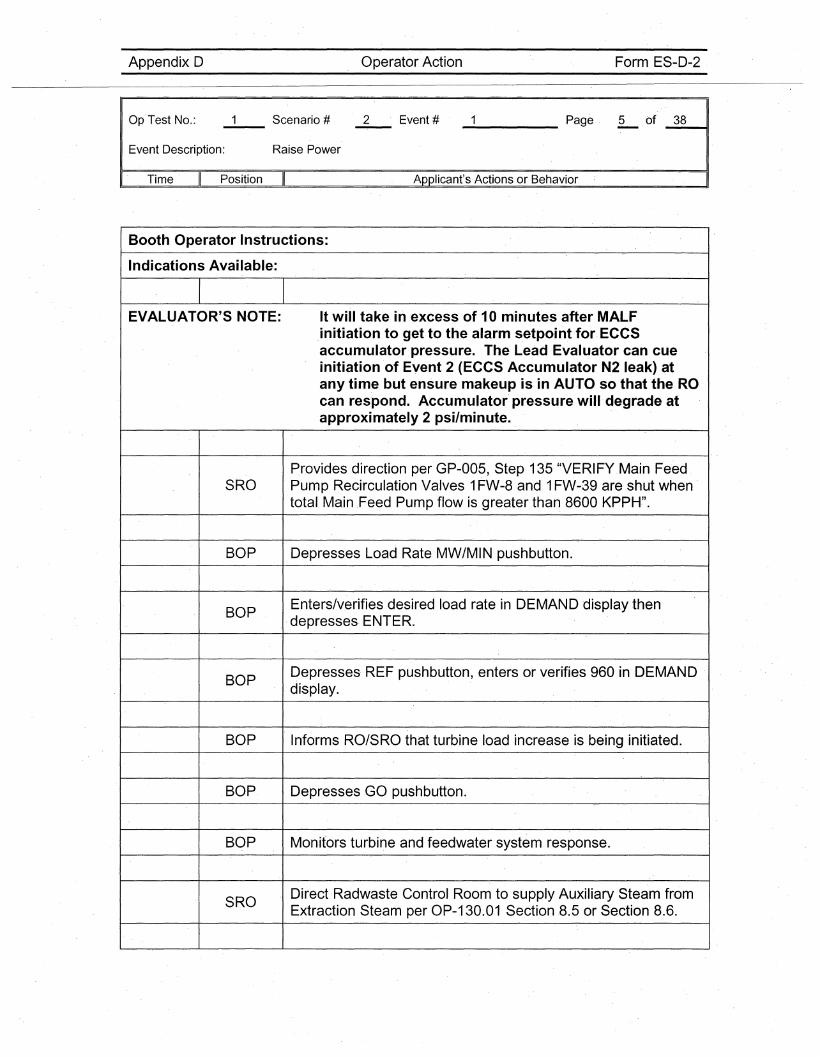
EVALUATOR'S NOTE: It will take in excess of 10 minutes after MALF,initiation to get to the alarm setpoint for ECCSaccumulator pressure. The Lead Evaluator can cueinitiation o,f Event 2 (ECCS Accumulator N2 leak) atany time but ensure makeup is in AUTO so that the ROcan respond. Accumulator' pressure will degrade atapproximately 2 psi/minute.
Provides direction per GP-005, Step 135 "VERIFY Main FeedSRO Pump Recirculation Valves 1FW-8 and 1FW-39 are shut when'
total Main ,Feed Pump flow is greater than 8600 KPPH".
BOP Depresses Load Rate MW/MIN pushbutton.
BOPEnters/verifies desired load rate in DEMAND display then
,depresses, ENTER.
BOPDepresses REF pushbutton, enters or verifies 960 in DEMANDdisplay.
BOP Informs RO/SRO that turbine load increase is being initiated.
BOP Depresses ,GO pushbutton.
BOP Monitors turbine and feedwater system response.
SRODirect'Radwaste Control Room to supply Auxiliary Steam fromExtraction Steam per OP-130.01 Section 8.5 or Section 8.6.

Operator ActionAppendix D
Op'Test No.:
Event Description:
Time II Position
Raise Power
Form ES-D-2
Page 6 of 38----- -~I
Applicant's Actions or Behavior
SIMULATOR OPERATOR: Respond as Radwaste Operator but 'no ·simulatoractions are required.
EVALUATOR'S NOTE: The crew may elect to start a dilution before the pow.erchange is initiated.
EVALUATOR'S NOTE: OP-107 i.s a "Reference Use" procedure.
DETERMINE the volume of makeup water to be added. ThisRO may be done by experience or via the reactivity plan associated
with the Simulator IC.
ROSETS FIS'-114, TOTAL MAKEUP WTR BATCH COUNTER, toobtain the ·des·ired quantity.
RO SET total makeup flow as follows:
• IF performing DIL in Step 8, .THEN SET controller1CS-151, FK-114' RWMU FLOW, for less than or equal to90 gpm.
• IF performing ALT DIL in Step 8, THEN SET controller1CS-151, FK-114 RWMU FLOW, for the. desired flow rate.
ROVERIFY the RMW CONTROL switch has been placed in theSTOP position.
RO' VERIFY the RMW CONTROL switch green light is lit.
ROPLACEthe control switch RMW MODE SELECTOR to the DILOR the ALT .DIL position.
Appendix D Operator Action Form ES-D-2
Op Test No.:
Event Description: Raise Power
_____ Page 7 of _3_8--11
Time Position Applicant's Actions or Behavior
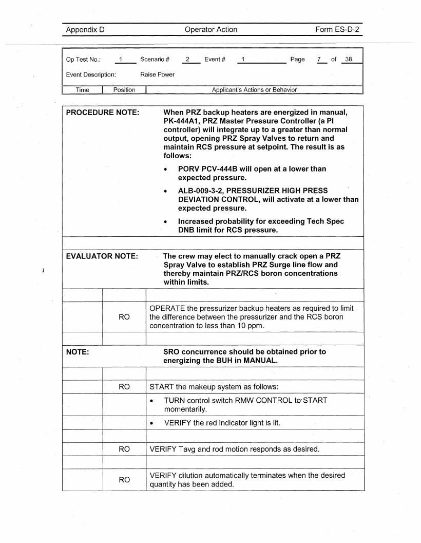
PROCEDURE NOTE: When PRZ backup heaters are. energized in manual,PK-444A1, PRZ Master Pressure Controller (a PIcontroller) will integrate up to a greater than normaloutput, opening PRZ Spray Valves to return andmaintain RCS pressure at setpoint. The result is asfollows:
• PORV PCV-444B will open at a lower thanexpected pressure.
• ALB-009-3-2, PRESSURIZER. HIGH PRESSDEVIATION CONTROL, will activate at a lower thanexpected pressure.
• Increased probability for exceeding Tech.SpecDNB limit for RCS pressure.
EVALUATOR NOTE: The crew may elect to manually crack open a PRZSpray Valve to establish PRZ Surge line flow andthereby maintain PRZ/RCS boron concentrationswithin limits.
OPERATE the pressurizer backup heaters as required to limit·RO the difference between the pressurizer and the RCS boron
concentration to less than 10 ppm.
NOTE: SRO concurrence should be obtained prior toenergizing the BUH in MANUAL.
RO START the makeup system as follows:
-. TURN control switch RMW CONTROL to'STARTmomentarily.
- VERIFY the red indicator light is lit.
RO VERIFY Tavg and rod motion responds as desired~
ROVERIFY dilution automatically terminates when the desiredquantity has b·een added.
Appendix D Operator Action Form ES-D-2
OpTest No.:
Event Description: Raise Power
_____ Page 8 of _3_8----.1
" Time Position Applicant's Actions or Behavior
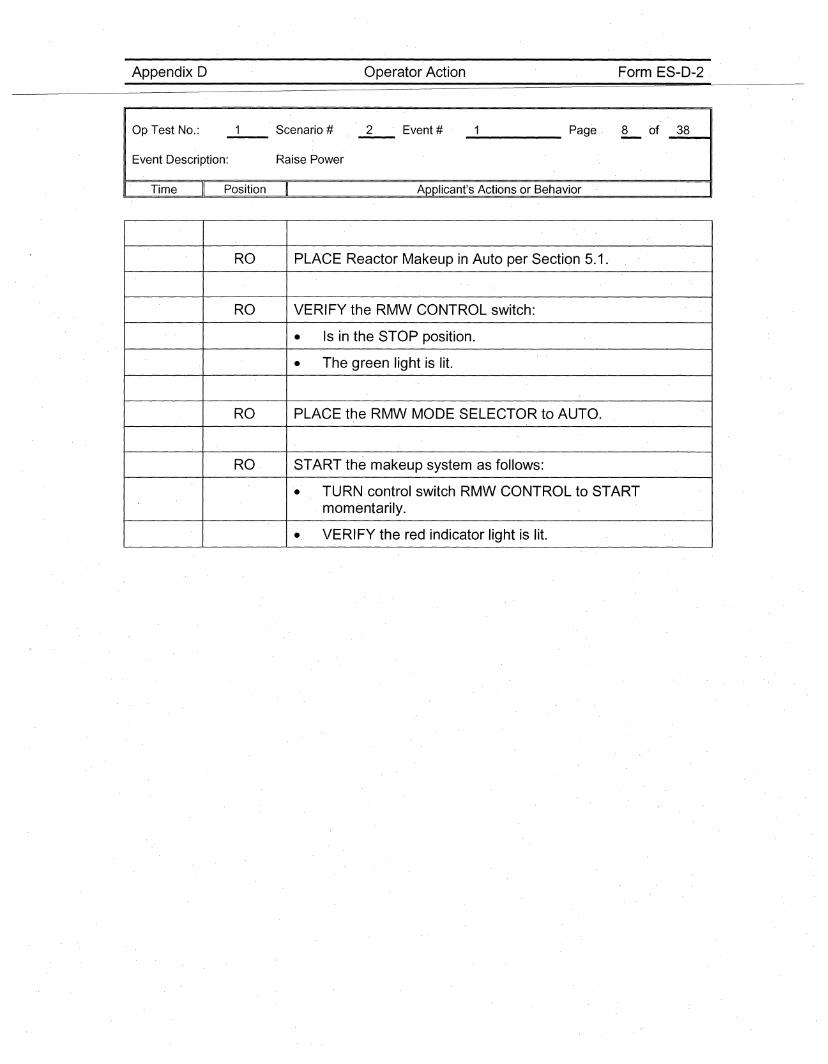
RO PLACE Reactor Makeup in Auto per Section 5.1.
RO VERIFY the RMW CONTROL switch:
• Is in the STOP position.
• The green light is lit.
RO PLACE the RMW MODE SELECTOR to AUTO.
RO START the makeup system as follows:
• TURN control switch RMW CONTROL to STARTmomentarily.
• VERIFY the red indicator light is lit.
Appendix D Operator Action Form ES-0-2
Op Test No.:
Event Description: ECCS Accumulator "A" N2 Leak
_2 Page 9 of _3_8----11
Time Position Applicant's Actions or Behavior
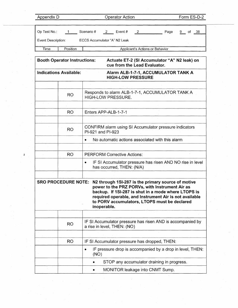
Booth Operator Instructions: Actuate ET-2 (SI Acc·umulator "A" N2 leak) oncue from the Lead Evaluator.
Indications Available: Alarm ALB~1-7-1,ACCUMULATOR TANK AHIGH-LOW PRESSURE
ROResponds to alarm ALB-1-7-1, ACCUMULATOR TANKAHIGH-LOW PRESSURE.
RO Enters APP-ALB-1-7-1
RO.CONFIRM alarm using SI Accumulator pressure indicatorsPI-921 and PI-923
• No automatic actions associated with this alarm
RO· PERFORM Corrective Actions:
• IF SI Accumulator pressure has risen AND NO rise in levelhas occurred, THEN: (N/A)
SRO PROCEDURE NOTE: N2 through.1 SI-287 is the primary source of motivepower to the PRZ PORVs, with Instrument Air asbackup. If 1SI-287 is shut in a mode where LTOPS isrequired operable, and Instrument Air is not availableto PORV accumulators, LTOPS must be declaredinoperable.
ROIF SI .. Accumulator pressure has risen AND is accompanied bya rise in level, ·THEN: (NO)
RO IF SI Accumulator pressure has dropped, THEN:
• IF pressure drop is accompanied by a drop in ·Ievel", THEN:(NO)
• STOP any accumulator draining in progress.
• MONITOR leak·age into CNMT Sump.
Appendix D Operator Action Form ES-D-2
Op, Test No.:
Event Description: ECCS Accumulator "A" N2 Leak
_2 Page 10 of. '_3_8~,
, Time Position Applicant's Actions or Behavior
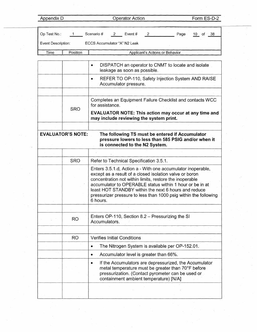
• DISPATC,H an operator to CNMT to locate and isolateleakage as soon as possible.
• REFER TO OP-110, Safety Injection System AND RAISE,Accumulator pressure.,
Completes an Equipment Failure Checklist and contacts WCCfor a'ssistance.
SROEVALUATOR NOTE: This action may occur at anytime andmay include reviewing the system print.
EVALUATOR'S NOTE: The following ,TS must be entered if Accumulatorpressure lowers to less than 585 PSIG and/or when' itis connected to the N2 System.
SRO, Refer to Tech'nical Specification 3.5.1.
Enters 3.5.1.d, Action a - With one accumulator inoperable,except ,as a result of a closed isolation valve or boronconcentration not within limits, restore the inoperableaccumulator to OPERABLE status within 1 hour or be in atleast HOT STANDBY within the next 6 hours and reducepressurizer pressure to less than 1000 psig' within the following6 hours.
ROEnters OP-11 0, Section 8.2 - Pressurizing the SIAccumulators.
RO Verifies Initial, Conditions
• The N'itrogen System is available per OP-152:0,1.
• Accumulator level is greater than 66%.
• If the Accumulators are depressurized, the Accumulatormetal temperature must be greater than 70°F beforepressurization. (Contact pyrometer can be used orcontainment ambient temperature) [NtA]
Appendix D Operator Action Form ES-D-2
Op Test No.:
Event Description: ECCS Accumulator "A" N2 Leak
_2 Page 11 of _3_8----11
Time Position Applicant's Actions or Behavior
\~
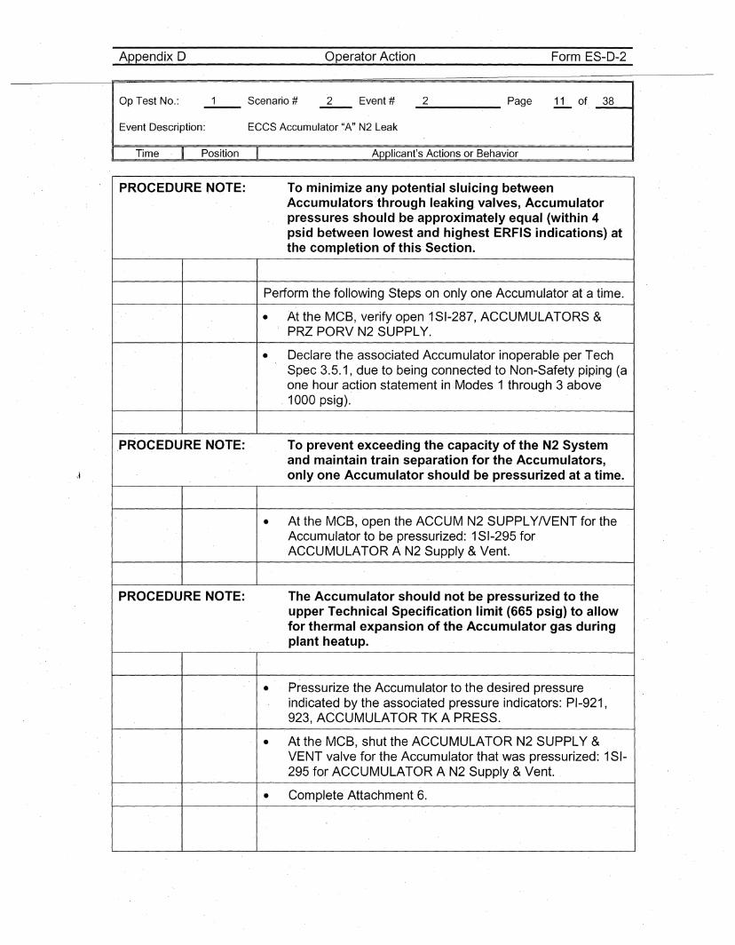
PROCEDURE NOTE: To minimize any potential sluicing betweenAccumulators'through leaking. valves, Accumulatorpressures should be ,approximately equal (within 4psid between 'Iowest and highest ERFIS indications) atthe completion of this Section.
Perform the following Steps on only one Accumulator at' a time.
• At the MCB, verify open .1SI-287, ACCUMULATORS &PRZ PORV N2 SUPPLY.
• Declare the associated Accumulator inoperable per TechSpec 3.5.1, due to being connected to Non-Safety piping (aone hour a~tion statement in .Modes 1 through 3 above
, 1000 psig).
PROCEDURE NOTE: To prevent exceeding the capacity of the N2 Systemand maintain train separation for the Accumulators,only one Accumulator should be pressurized at 'a time.
• At the MCB, open the ACCUM N2 SUPPLY/VENT for theAccumulator to be pressurized: 1SI-295 forACCUMULATOR A N2 Supply &Vent.
P'ROCEDURE NOTE: The Accumulator should not be pressurized to theupper Technical Specification limit (665 psig) to allowfor thermal expansion of the Accumulator gas duringplant heatup.
• Pressurize the Accumulator to the desired pressureindicated by the associated pressure indicators: PI-921,923, ACCUMULATOR TK A PRESS.
• At the MCB, shut the ACCUMULATOR N2 SUPPLY &VENT valve for the Accumulator that was pressurized: 1SI-295 for ACCUMULATOR A N2 Supply &Vent.
'. Complete Attachment 6.
Appendix D Operator Action Form 'ES-D-2
Op Test No.: 2 Event # _2 Page 12 of _3_8_-41
Event Description: ECC'S Accumulator "A" N2 Leak
Time Position Applicant's Actions or Behavior
I IEVAL"UATOR'5 NOTE: The Lead Evaluator can cue Event 3 (N5W Pump shaft
shear) after the T5 entry is complete and 151-295 isclosed.
I I
Appendix D Operator Action Form ES-D-2
OpTest No.:
Event Description: NSW Pump "A" shaft shear
_3 Page 13 of. _3_8---41
Time Position Applicant's Actions or Behavior
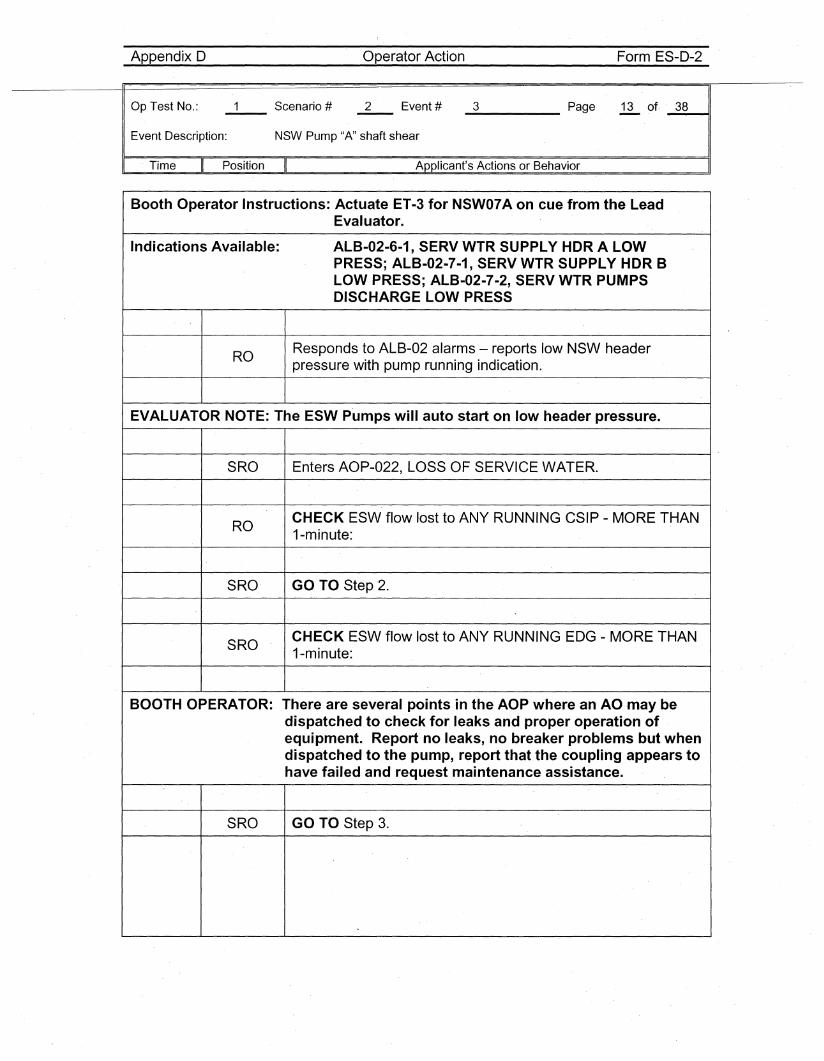
Booth Operator Instructions: Actuate ET-3 for NSW07A on cue from the LeadEvaluator.
Indications Available: ALB-02-6-1, SERV WTR SUPPLY HDR A LOWPRESS; ALB-02-7-1., SERV WTR SUPPLY HDR BLOW PRESS; ALB-02-7-2, SERV WTR PUMPSDISCHARGE LOW PRESS
ROResponds to ALB~02 alarms - reports low NSW headerpressure with pump running indication.
EVALUATOR NOTE: The ESW P·umpswill auto start on low header pressure.
SRO Enters AOP-022, LOSS OF SERVICE WATER.
ROCHECK ESW flow lost to ANY RUNNING CSIP - MORE THAN1-minute:
SRO GO TO Step 2.
SROCHECK ESW flow lost to ANY RUNNING EDG - MORE THAN1-minute:
BOOTH OPERATOR: There are several points in the AOP where an AO ·may bedispatched to check for leaks and proper operation ofequipment. Report no leaks, no breaker problems but whendispatched to the pump, report that the coupling appears tohave failed and request maintenance assistance.
SRO GO TO Step 3.
Appendix D Operator Action Form ES-D-2
Op Test No.:
Event Description: NSW Pump "A" shaft shear
_3 Page 14 of _3_8--11
Time Position Applicant's Actions or Behavior
\~
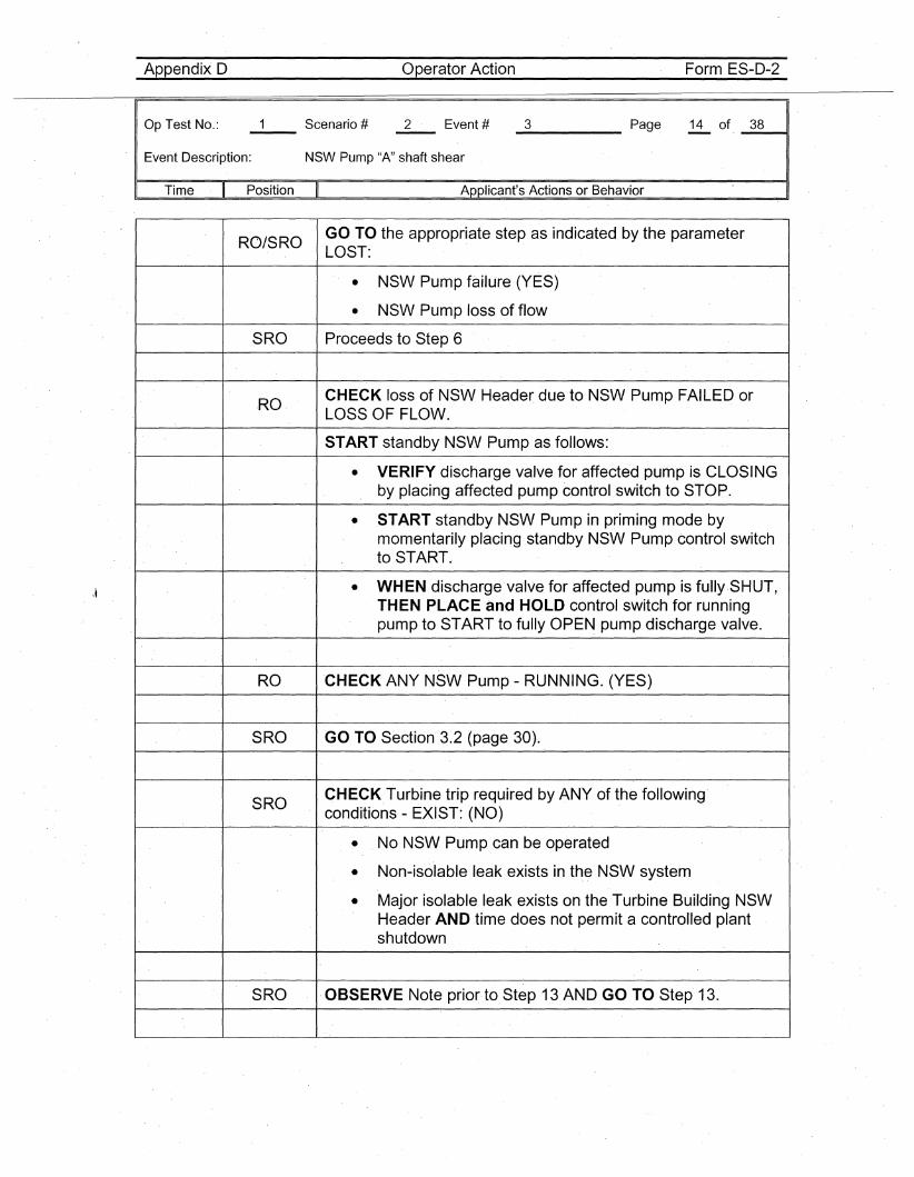
RO/SROGO TO the appropriate step as indicated by the parameterLOST:
• NSW Pump failUre (YES)
• NSW Pump loss of flow
SRO Proceeds to Step 6
.RO. CHECK loss of NSW Header due to NSW Pump FAILED orLOSS OF FLOW.
START standby NSW Pump as follows:
• VERIFY discharge valve for affected pump is CLOSINGby placing affected pump control switch to STOP.
• START standby NSWPump in priming mode bymomentarily placing standby NSWPump control switchto START.
• WHEN discharge valve for affected pump is fu"lly.SHUT,THEN PLACE and HOLD control switch for runningpump to START to fuHy OPEN pump discharge valve.
RO CHECK ANY NSW Pump - RUNNING. (YES)
SRO GO TO Section· 3.2 (page 30).
SROCHECK.Turbine trip required by ANY of the following·conditions - EXIST: (NO)
• No NSW Pump can be operated
• Non-isolable leak exists in theNSW system
• Major isolable leak exists on the Turbine Building NSWHeader AND time does not permit a controlled plantshutdown
SRO OBSERVE Note prior-to Step 13 AND GO TO Step· 13.
Appendix D Operator Action Form ES-D-2
Op.Test No.:
Event Description: NSW Pump "A" shaft shear
_3_____ Page 15 of· _.3_8----41
. Time Position Applicant's Actions or Behavior
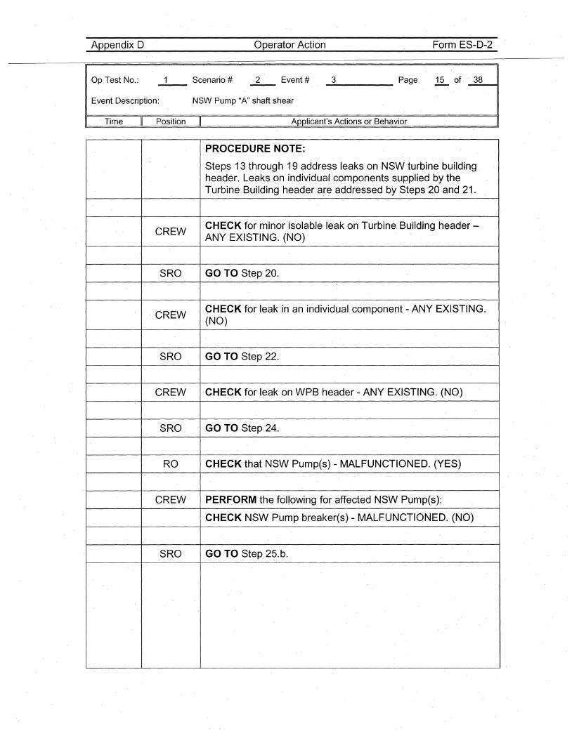
PROCEDURE NOTE:
Steps 13 through 19 address leaks on NSW turbine buildingheader. Leaks on individual components supplied by theTurbine Building header are addressed by Steps 20 and 21.
CREWCHECK for minor isolable leak on Turbine Building header-ANY EXISTING. (NO)
SRO GO TO Step 20.
CREWCHECK for leak in an individual component - ANY EXISTING.(NO)
SRO GOTO Ste'p 22.
CREW CHECK for leak on WPB header - ANY EXISTING. (NO)
SRO GO TO Step 24.
RO CHECK that NSW.Pump(s) - MALFUNCTIONED. (YES)
CREW PERFORM the following for affected NSW Pump(s):
CHECK NSW Pump breaker(s) - MALFUNCTIONED. (NO)
SRO GO TO Step 25.b.
Appendix D Operator Action Form ES-D-2
Op Test No.:
Event Description: NSW Pump "A" shaft shear
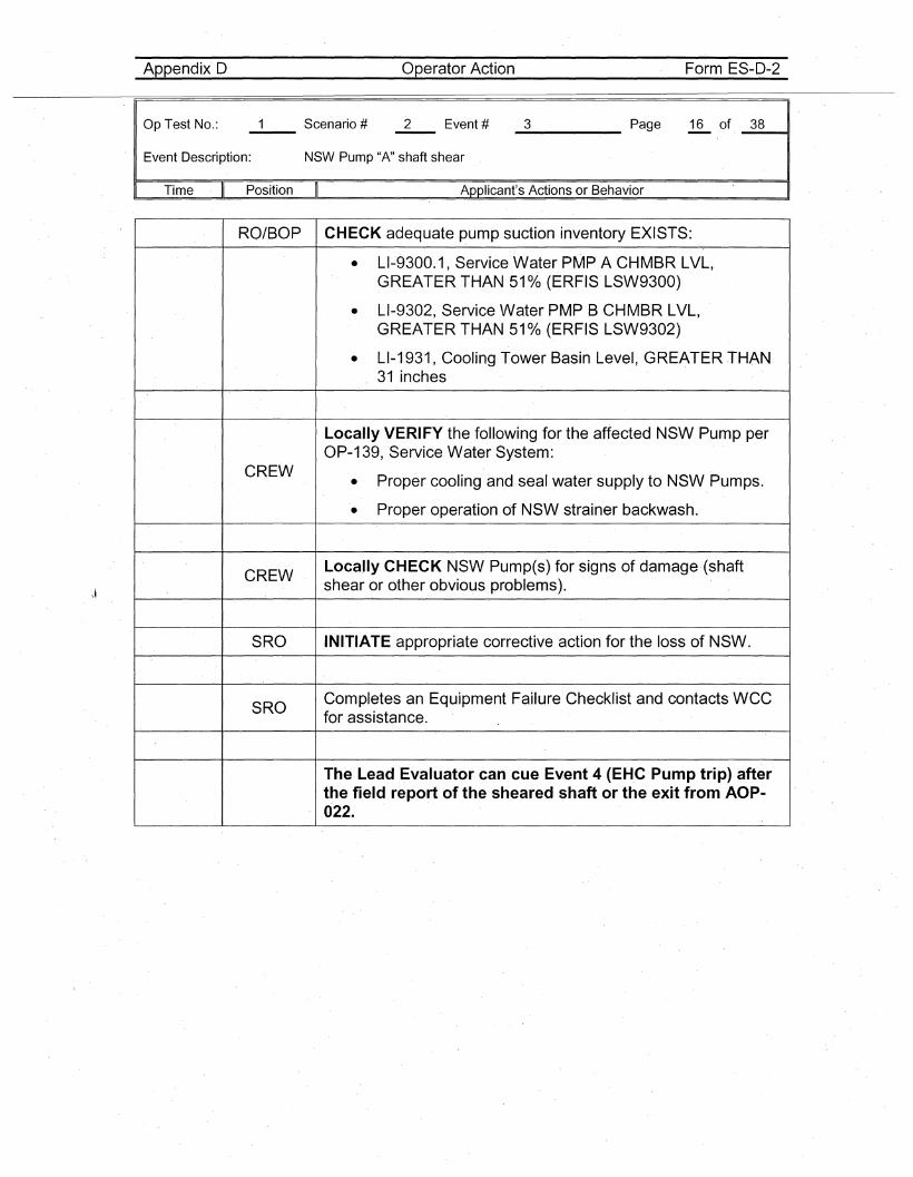
_3 Page 16 of _3_8~,
Time II Position II Applicant's Actions or Behavior
RQ/BOP CHECK adequate pump suction inventory EXISTS:
• LI-9300.1, Service Water PMP A CHMBR LVL,GREATER THAN 510/0 (ERFIS·LSW9300)
• LI-9302, Service Water PMP B CHMBR LVL,GREATER THAN 510/0 (ERFIS LSW9302)
• LI-1931, Cooling Tower Basin Level, GREATER THAN31 inches
Locally VERIFY the following for the affected NSW Pump perOP-139, Service Water System:
CREWProper cooling and seal water supply to NSW Pumps.•
• Proper operation of NSW strainer backwash.
CREWLocally CHECK NSW Pump(s) for signs of damage (shaftshear or other obvious problems).
SRO INITIATE appropriate corrective action for the loss of NSW.
SROCompletes an Equipment Failure Checklist and contacts WCCfor assistance.
The Lead Evaluator can cue Event 4 (EH.C Pump trip) afterthe field report of the sheared shaft or the exit from AOP-022.
Appendix D Operator Action Form ES-D-2
Op Test No.:
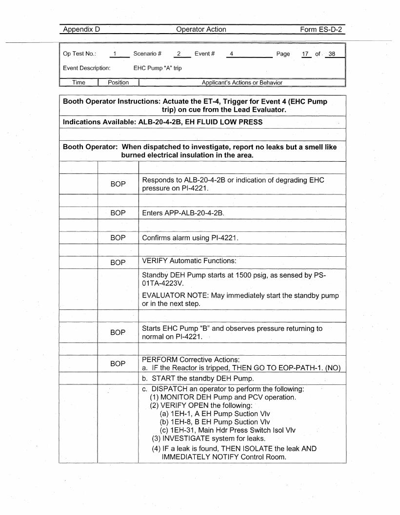
Event Description: EHC Pump "A" trip
_4_. Page 17 of - _3_8---11
Time Position Applicant's Actions or Behavior
Booth Operator Instructions: Actuate the ET-4, Trigger for Event 4 (EHC Pumptrip) on cue from the Lead Evaluator.
Indications Available: ALB-20-4-2B, EH FLUID LOW PRESS
Booth Operator: When dispatched to investigate, report no leaks but a smell likeburned electrical insulation in the area.
BOPResponds to ALB-20-4-2Bor indication of degrading EHC _pressure on PI-4221.
BOP Enters APP-ALB-20~4-2B.
BOP Confirms alarm using PI-4221.
BOP VERIFY Automatic Functions:
Standby DEH Pump starts at 1500 psig, as sensed by PS-01TA-4223V.
EVALUATOR NOTE: May immediately start the standby pumpor in the next step.
BOPStarts EHC Pump "B" and observes pressure returning tonormal on PI-4221.
BOPPERFORM Corrective Actions:a. IF the Reactor is tripped, THEN GO TO EOP-PATH-1. (NO)
b. START the standbyDEH Pump.
c. DISPATCH an operator to perform-the following:(1) MONITOR-DEH Pump and PCVoperation.(2) _VERIFY OPEN the following: -
(a) 1EH-1, A EH Pump Suction Vlv(b) 1EH-8, B- EH Pump Suction Vlv(c) 1EH-31, Main Hdr Press Switch Isol Vlv
(3) INVESTIGATE system for leaks.
(4) IF a leak is found, THEN ISOLATE the leak ANDIMMEDIATELY NOTIFY Control Room.
Appendix D Operator·Actio·n Form ES-D-2
Op.Test No.: Scenario #-- 2 Event # _4 Page 18 of· _3_8----41
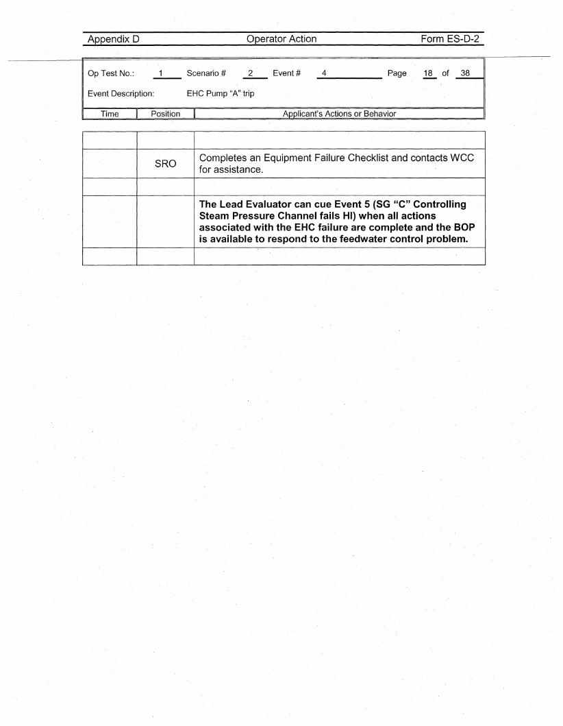
Event Description: EHC Pump "A" trip
Time Position Applicant's Actions or Behavior
SROCompletes an Equipment Failure Checklist and contacts wecfor assistance.
The Lead Evaluator can cue Event 5 (SG "C" ControllingSteam Pressure Channel fails HI) when all actionsassociated with the EHC failure are complete and the BOPis available to respond to the feedwater control problem.
Appendix D Operator Action Form ES-D-2
Op Test No.:
Event Description:
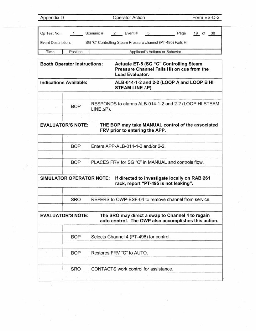
__5 Page 19 of _3_8~,
SG "C" Controlling Steam Pressure channel (PT-495) Fails HI
Time Position Applicant's Actions or Behavior
Booth Operator Instructions: Actuate ET-5 (SG "C" Controlling SteamPressure Channel Fails HI) on cue from theLead Evaluator.'
Indications Available: ALB-014-1-2 and 2-2 (LOOP A and LOOP B HISTEAM LINE ~P)
BOPRESPONDS to alarms ALB-014-1-2 and 2-2 (LOOP HI STEAMLINE ~P).
EVALUATOR'S NOTE: THE BOP may take MANUAL control of the associatedFRV prior to entering the APP.
BOP Enters APP-ALB-014-1-2 and/or 2-2.
BOP PLACES FRV for SG "C" in MANUAL and controls flow.
SIMULATOR OPERATOR NOTE: If directed to investigate locally on RAB 261rack, report "PT-495 is not leaking".
SRO REFERS to OWP-ESF-04 to remove channel from ·service.
EVALUATOR'S NOTE: The SRO may direct a swap to Chann·el 4 to regainauto control. The OWP also accomplishes this action.
BOP Selects Channel 4 (PT-496) for control.
BOP Restores FRV "C" to AUTO.
SRO CONTACTS work control for assistance.
Appendix D Operator Action Form ES-D-2
Op ,Test No.: Scenario #-"""--
2 Event # _5 Page 20 of, _'3_8---t1
Event Description: SG "C", Controlling Steam Pressure channel (PT-49.5) Fails HI
Time Position Applicant's Actions or Behavior
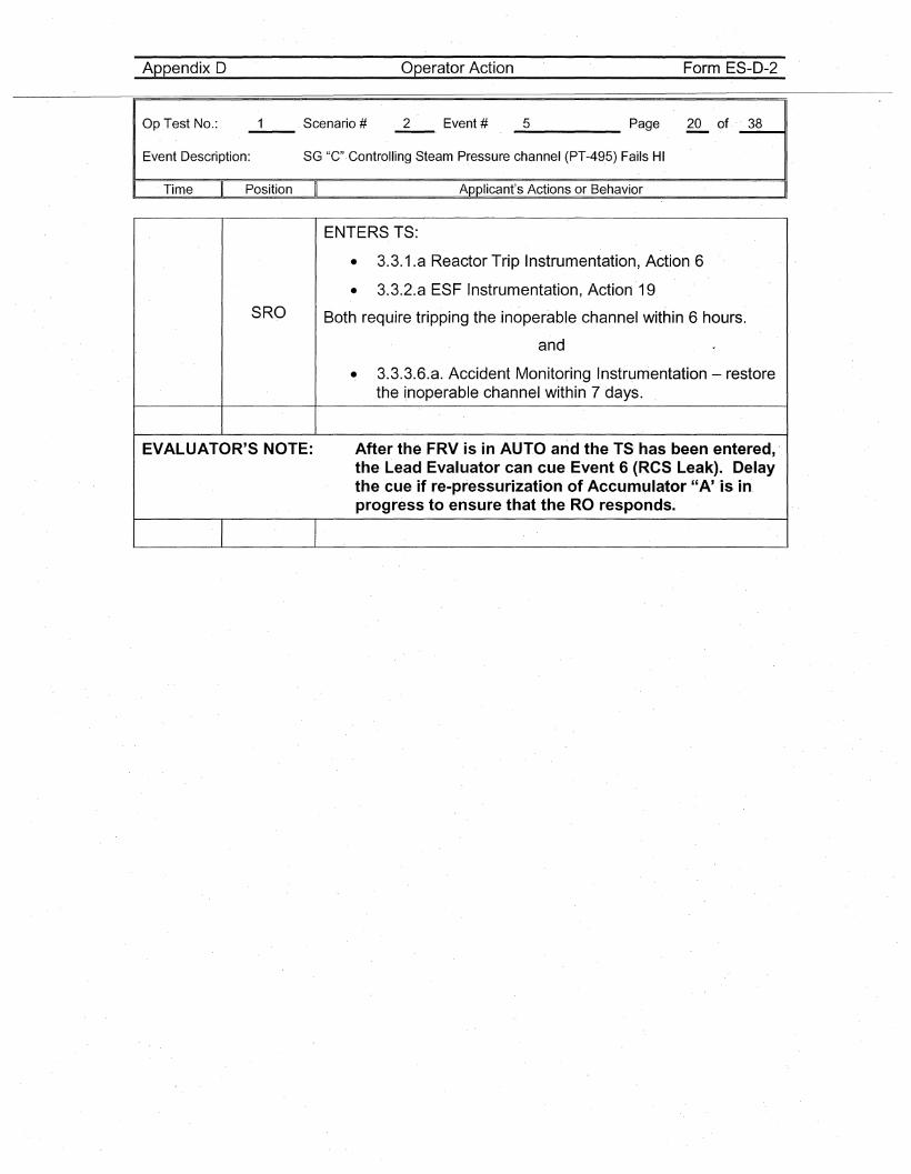
ENTERS TS:
• 3.3.1.a Reactor Trip Instrumentation, Action 6
• 3.3.2.a ESF Instrumentation, Action 19
SRO Both require tripping the inoperable channel within 6 hours.
and
• 3.3.3.6.a. Accident Monitoring Instrumentation - restorethe i,noperable channel within 7 days.
EVALUATOR'S NOTE: After the FRV is in AUTO and the TS has been entered, 'the Lead Evaluator can cue Event 6 (ReS Leak). Delaythe cue if re-pressurization of Accumulator "A' 'is in,progress to ensure that the RO responds.
Appendix 0
Op Test No.: Scenario #--
Operator Action
All Event #
Form ES-D-2
_6 Page ~ of _3_8__••11
Event Description: Progressive RCS Leak, FCV-122, Charging Flow Control Valve, Fails to RaiseCharging Flow
Time Position Applicant's Actions or Behavior . I
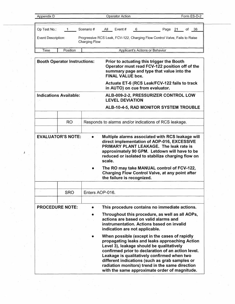
Booth Operator Instructions: Prior to actuating this trigger the BoothOperator must read FCV-122 position off of thesummary page and type that value into theFINAL VALUE box.
ActuateET-6 (RCS Leak/FCV-122 fails to trackin AUTO) on cue from evaluator.
Indications Available: ALB-009-2-2, PRESSURIZER'CONTROL LOWLEVEL DEVIATION
ALB~10-4-5, RAD MONITOR SYSTEM TROUBLE
RO Responds to alarms and/or indications of ReS leakage.
EVALUATOR'S NOTE: • Multiple alarms associated with RCSleakage willdirect implementation of AOP-016, EXCESSIVEPRIMARY PLANT LEAKAGE. The leak rate isapproximately 90 GPM. Letdown will have to bereduced or isolated to stabilize charging flow onscale.
• The RO may take MANUAL control of"FCV-122,Charging Flow Control Valve, at any point afterthe failure is recognized.
SRO Enters AOP-016.
PROCEDURE NOTE: . • This procedure contains no immediate actions.
• Throughout this procedure, as well as all AOPs,actions are based on valid alarms andinstrumentation. Actions based on invalidindication are not applicable.
• When possible (except in the cases of rapidlypropagating leaks and leaks approaching ActionLevel 3), leakage should be qualitativelyconfirmed prior to declaration of an action level.Leakage is. qualitatively confirmed when twodifferent indications (such as grab samples orradiation monitors) trend in the same directionwith the· same approximate order of magnitude.
Appendix D
Op Test No.:
Operator Action
All Event #
Form ES-D-2
_6 Page ~ of. _3_8--41
Event Description: Progressive RCS Leak, FCV-122, Charging Flow Control Valve, Fails to RaiseCharging Flow
I· Time Position Applicant's Actions or Behavior
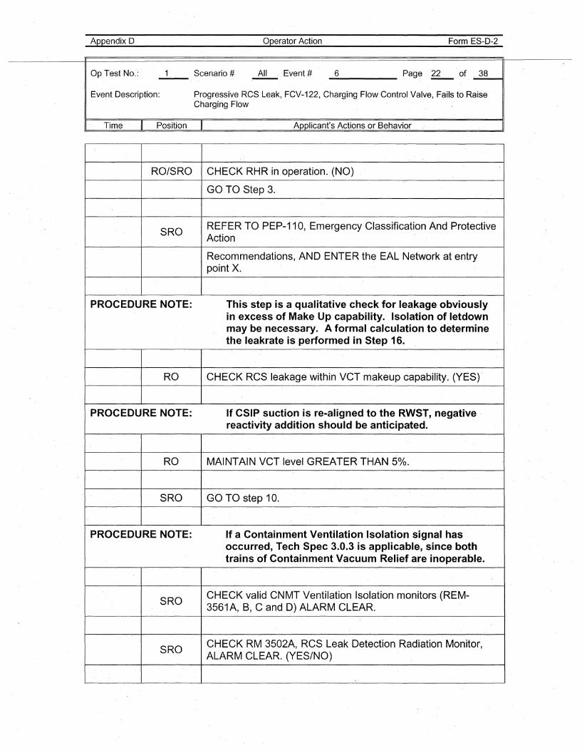
RO/SRO CHECK RHR in operation. (NO)
GO.TO Step 3.
SROREFER TO PEP-11 0, Emergency Classification And ProtectiveAction
Recommendations, AND ENTER the EAL Network at entrypoint X.
PROCEDURE NOTE: This step is a qualitative check for leakage obviouslyin excess of Make Up capability. Isolation of letdownmay be necessary_ A formal calculation to determinethe leakrate is performed in Step 16.
RO CHECK RCS leakage within VCT makeup capability. (YES)'
PROCEDURE NOTE: If CSIP suction is re-aligned to the RWST, negativereactivity addition should be anticipated.
RO MAINTAIN VCTlevel GREATER THAN 50/0.
SRO GO TO step 10.
PROCEDURE NOTE: If a Containment Ventilation Isolation signal hasoccurred, Tech Spec 3.0.3 is applicable, since bothtrains 'of Containment Vacuum Reliefare inoperable.
SROCHECK valid CNMT Ventilation Isolation monitors (REM-3561A, B, CandO) ALARM CLEAR.
SROCHECK RM 3502A, RCS Leak Detection Radiation Monitor,ALARM CLEAR. (YES/NO)
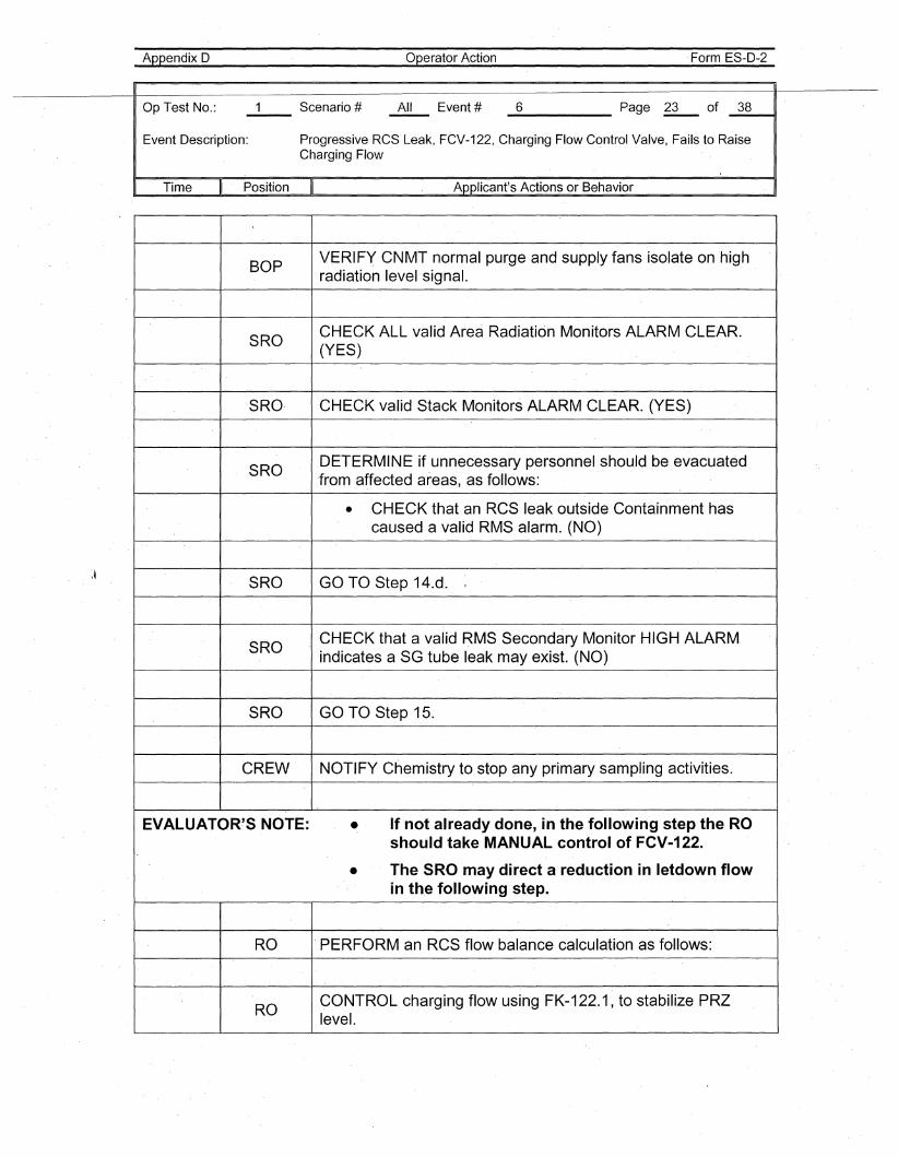
Appendix D Operator Action Form ES-D-2
\~
Op Test No.: 1 Scenario # All Event # 6 Page 23 of 38--Event Description: Progressive RCS Leak, FCV-122, Charging Flow Control Valve, Fails to Raise
Charging Flow
I Time II Position II Applicant's Actions or Behavior I
BOPVERIFY CNMT normal purge and supply fans isolate on highradiation level signal.
SROCHECK ALL valid Area Radiation Monitors ALARM CLEAR.(YES)
SRO· CHECK valid Stack Monitors ALARM CLEAR. (YES)
SRODETERMINE if unnecessary personnel should be evacuated'fromaffected areas, as follows:
• CHECK that an RCS leak outside Containment hascaused a valid RMS alarm. (NO)
SRO GO TO Step 14.d.
SROCHECK that a valid RMS Secondary Monitor HIGH ALARM.indicates a SG tube leak may exist. (NO)
SRO GO TO Step 15.
CREW NOTIFY Chemistry to stop any primary sampling activities.
EVALUATOR'S NOTE: • If not already done, in the following step the ROsh.ould take MANUAL control of FCV-122.
• The SRO may direct a reduction in letdown flowin the following step.
RO .PERFORM an RCS flow balance calculation as follows:
ROCONTROL charging flow using FK-122.1, to stabilize PRZlevel.
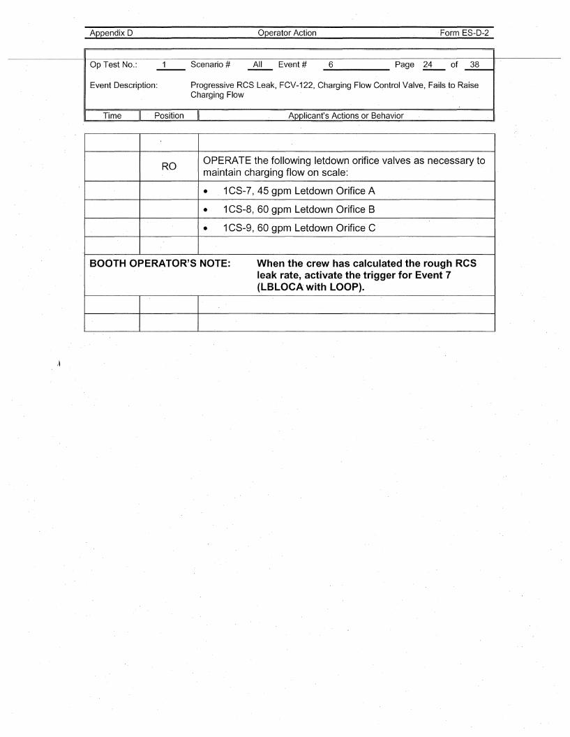
Appendix D Operator Action Form ES-D-2
Op Test No.: 1 Scenario # All Event # 6 Page 24 of 38--Event Description: Progressive RCS Leak, FCV-122, Charging Flow Control Valve, Fails to Raise
Charging Flow
I Time II Position II Applicant's Actions or Behavior . I
ROOPERATE the following letdown orifice valves as necessary tomaintain charging flow on scale:
• . 1CS-7, 45 gpm Letdown Orifice A
• 1CS-8, 60 gpm Letdown Orifice B
• 1CS-9, 60 gpm Letdown Orifice C
·BOOTH OPERATOR'S NOTE: When the crew has calculated the rough RCSleak rate, activate the trigger for Event 7(LBLOCA with LOOP).
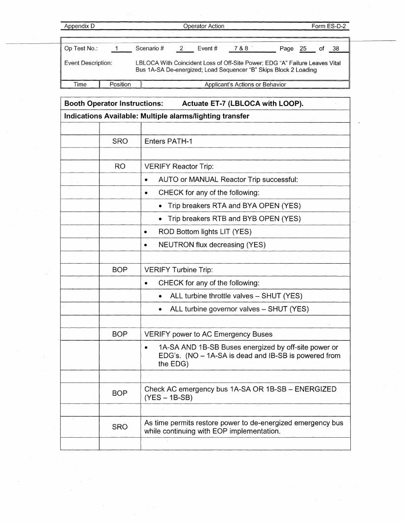
Appendix D Operator Action Form ES-D-2
Op Test No.: 1 Scenario # 2 Event # 7&8' Page 25 of 38
Event Description: LBLOCA With Coincident Loss of Off-Site Power; EDG "A" Failure Leaves VitalBus 1A-SA De-energized; Load Sequencer "B" Skips Block 2 Loading
I Time II Position II Applicant's Actions or Behavior I
Booth Operator Instructions: Actuate ET-7 (LBLOCA with LOOP).
Indications Available: Multiple alarms/lighting transfer
SRO Enters PATH-1
RO VERIFY Reactor Trip:
• AUTO or MANUAL Reactor Trip successful:
• CHECK for any of the following:
• Trip breakers RTA and BYA OPEN (YES)
• Trip breakers RTBand BYB OPEN (YES)
• ROD Bottom lights LIT (YES)
• NEUTRON flux decreasing (YES)
BOP VERIFY Turbine Trip:
• CHECK for any of the following:
• ALL turbine throttle valves - SHUT (YES)
• ALL turbine governor valves - SHUT (YES)
BOP VERIFY power to AC Emergency Buses,
• 1A-SA AND 1B-SB Buses energized by off-site power orEDG's. (NO ~ 1A-SA is dead and IB-SB is powered fromthe EDG)
BOPCheck AC emergency bus tA-SA OR 1B-SB ~ ENERGIZED(YES - 1B-SB)
SROAs time permits restore power to de-energized emergency buswhile continuing with EOP implementation.
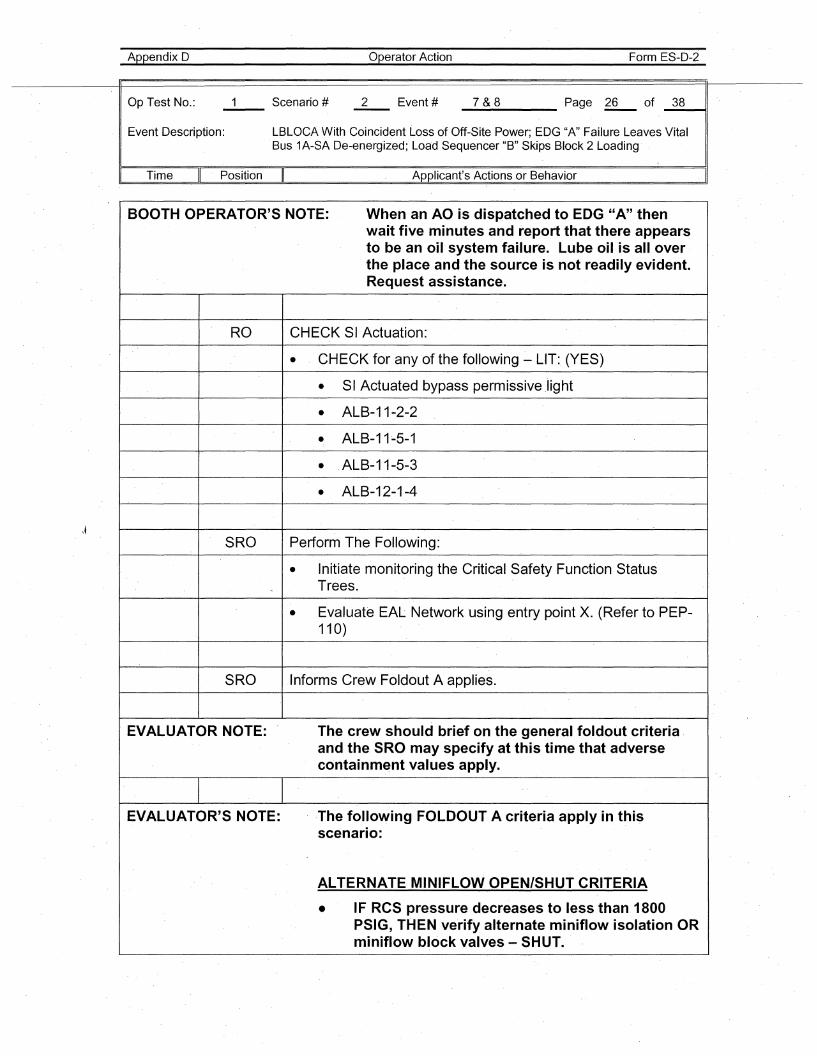
Appendix D
Op Test No.:
Operator Action Form ES-D-2
_7_&_8 Page ~ of _3_8--41
Event Description: LBLOCA With Coincident Loss of Off-Site Power; EDG "A" Failure Leaves VitalBus 1A-SA De-energized; Loa'd Sequencer "B" Skips Block 2 Loading
Time Position Applicant's Actions or Behavior ,I
\~
BOOTH OPERATOR'S NOTE: When an AO is dispatched to EDG "A" thenwait five minutes and report that there appearsto be an oil'system failure. Lube oil is all overthe place and the source is not readily evident.Request assistance.
RO CHECK SI Actuation:
• CHECK for any of the following - LIT:, (YES)
• SI Actuated bypass permissive ,light
• ALB-11-2-2
• ALB-11~5-1
• ALB-11-5-3
• ALB-12-1-4
SRO Perform The Following:
• Initiate monitoring the Critical Safety Function StatusTrees.
• Evaluate EAL Network using entry point X. (Refer to PEP-110)
SRO Informs Crew Foldout A applies.
EVALUATOR NOTE: The crew should brief on the general foldout criteria,and the SRO may specify at this time that adverse'containment values apply.
EVALUATOR'S NOTE: ,The following FOLDOUT A criteria apply in thisscenario:
ALTERNATE MINIFLOW OPEN/SHUT CRITERIA
• IF RCS pressure decreases to less than 1800PSIG, THEN verify alternate miniflow isolation ORminiflow block valves - SHUT.
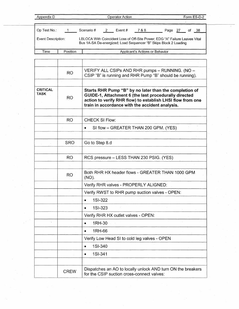
Appendix 0
Op Test No.:
Operator Action Form ES-O-2
_7_&_8 Page ~ of. _3_8---41
Event Oescription: LBLOCA With Coincident Loss of Off-Site Power; EOG "A" Failure' Leaves VitalBus 1A-SA O'e-energized; Load Sequencer "B" Skips Block 2 Loading
I, Time Position II Applicant's Actions or Behavior
ROVERIFY ALL CSIPs AND RHR pumps - RUNNING. (NO -CSIP "B" is running and RHR Pump "B" should be running).
CRITICAL Starts RHR Pump "8" by no later than the completion ofTASK GUIDE·1, Attachment 6 (the last procedurally directed
ROaction to verify RHR flow) to establish LHSI flow from onetrain in accordance with the accident analysis.
RO CHECK SI Flow:
• SI flow - GREATER THAN 200 GPM. (YES)
SRO Go, to Step8.d
RO RCS pressure -,LESS THAN 230 PSIG. (YES)
ROBoth RHR HX header flows - GREATER THAN 1000'GPM(NO).
Verify RHR valves - PROPERLY ALIGNED:
Verify RWST to RHR pump suction valves - OPEN:
• 1SI-322
• 1SI-323
Verify RHR HX outlet valves - OPEN:
• 1RH-30
• 1RH-66
Verify,Low HeadSI to cold leg valves - OPEN
• 1SI-340
• 1SI-341
CREWDispatches an AO to locally unlock AND turn ON the breakersfor the CSIP suction cross-connect valves:
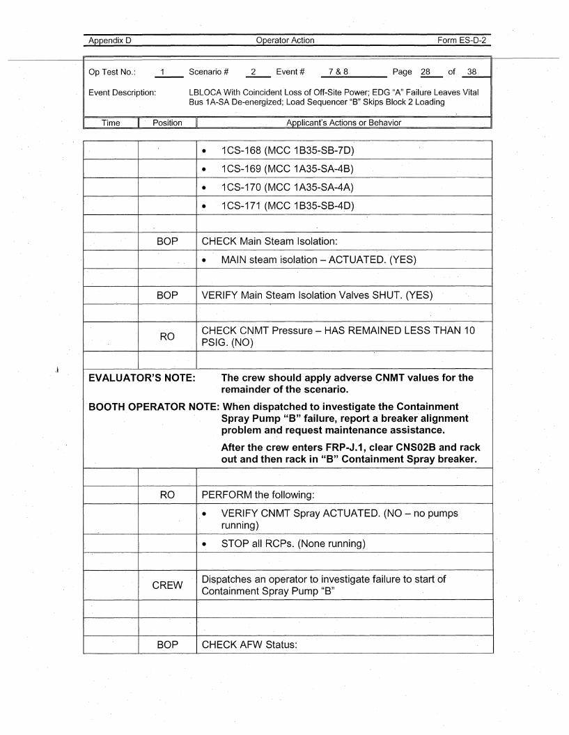
Appendix D
Op Test No.:
Operator Action Form ES-D-2
_7_&_8 Page ~ of _3_8--11
Event Description: LBLOCA With Coincident Loss of Off-Site Power; EDG "A"Failure Leaves VitalBus 1A-SA De-energized; Load Sequencer "B" Skips Block 2 Loading
Time Position Applicant's Actions or Behavior . I
• 1CS-168 (MCC 1B35-SB-7D)
• 1CS-169 (MCC1A35-SA-4B)
• 1CS-170 (MCC 1A35-SA-4A)
• 1CS-171 (MCC1 B35-SB-4.D)
BOP CHECK Main Steam Isolation:
• MAIN steam· isolation -ACTUATED. (YES)
BOP VERIFY Main Steam Isolation Valves SHUT. (YES)
ROCHECK CNMT Pressure - HAS REMAINED LESS THAN 10PSIG. (NO)
EVALUATOR'S NOTE: The crew should ·apply adverse CNMT values for theremainder of the scenario.
.BOOTH.OPERATOR NOTE: When dispatched to investigate the ContainmentSpray Pump "B" failure, report a breaker alignmentproblem and request maintenance assistance.
After the crew enters FRP-J.1, clear CNS02B and rackout and th·en rack in "B" Containment Spray breaker.
RO PERFORM thE? following:
• VERIFY CNMT Spray ACTUATED. (NO - no pumpsrunning)
• STOP aU RCPs. (None running)
CREWDispatches an operator to investigate failure to start ofContainment Spray Pump "B"
BOP CHECK AFW Status:
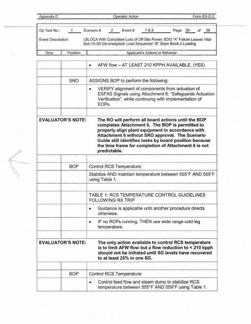
Appendix D Operator Action Form ES-D-2
Op Test No.: 1 Scenario # 2 Event # 7&8 Page 29 of 38
Event Description: LBLOCA With Coincident Loss of Off-Site Power; EDG "A" Failure Leaves VitalBus 1A-SA De-energized; Load Sequencer "B" Skips Block 2 Loading
I· Time II Position II Applicant's Actions or Behavior
• AFW flow - AT LEAST 210 KPPH.AVAILABLE. (YES)
SRO ASSIGNS BOP to perform the following:
• VERIFY alignment of components from actuation ofESFAS Signals using Attachment 6, "Safeguards ActuationVerification", while continuing with implementation ofEOPs.
EVALUATOR'S NOTE: The ROwili perform all board actions until the BOPcompletes Attachment 6. The B·OP is permitted toproperly align ·plant equipment in accordance withAttachment 6 without SRO approval. The ·ScenarioGuide still identifies tasks by board position becausethe time frame for completion of Attachment 6 is notpredictable.
BOP Control RCS Temperature:
Stabilize AND maintain temperature between 555°F AND 559°F.using Table 1.
TABLE 1: RCS TEMPERATURE CONTROL GUIDELINESFOLLOWING RX TRIP
.. Guidance is applicable until another procedure directsotherwise.
• IF no RCPs running, THEN use wide range cold legtemperature.
EVALUATOR'·S NOTE: The only action available to control ReS temperatureis to limit AFW flow but a flow reduction to <210 kpphs·hould not be initiated until SG levels have recoveredto at least 250/0 in one SG.
BOP Control RCS Temperature:
• Control feed flow and steam dump to stabilize RCStemperature between 555°F AND 559°F using Table 1.
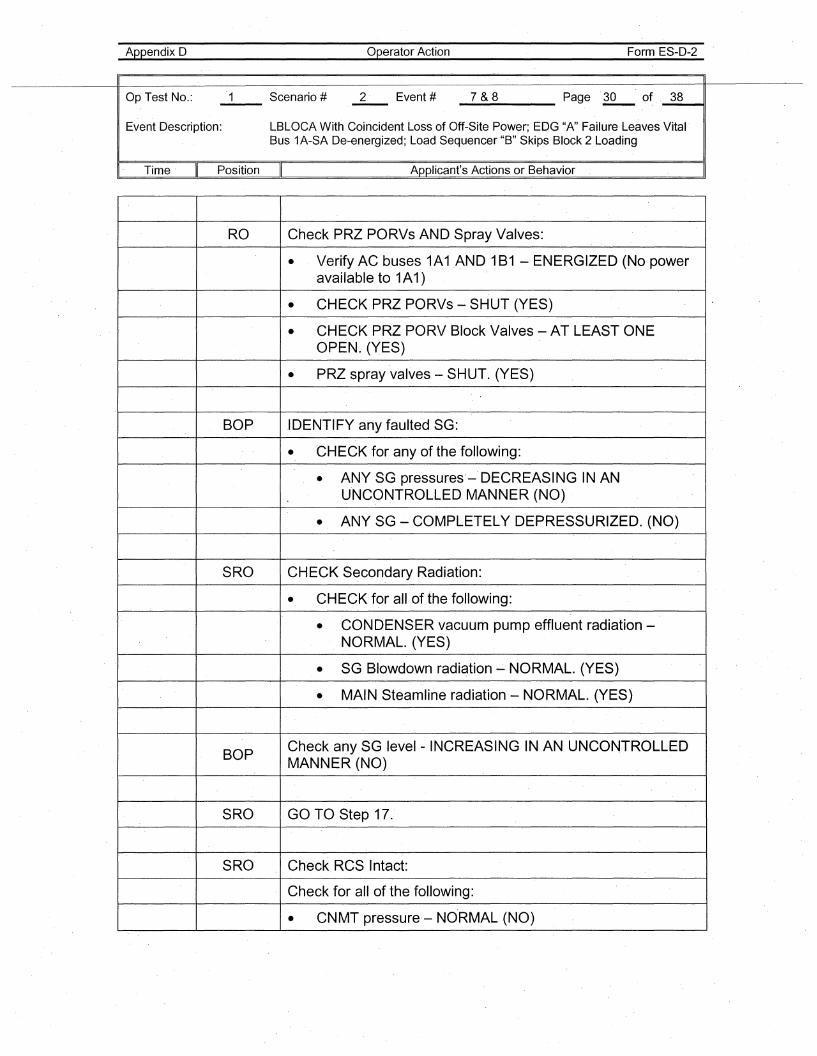
Appendix D Operator Action Form ES-D-2
Op Test No.: 1 Scenario # 2- Event # 7&8 Page 30 of 38
Event Description: LBLOCA With Coincident Loss of Off-Site Power; EDG "A" Failure Leaves VitalBus 1A-SA De-energized; Load Sequencer "B" Skips Block 2 Loading
I- Time II Position II Applicant's Actions or Behavior
RO Check PRZ PORVs AND Spray V-alves:
• Verify AC buses 1A1AND 1B1 - ENERGIZED (No poweravailable to 1A1)
• CHECK PRZPORVs - SHUT (YES)
• CHECK PRZPORV Block Valves - AT LEAST ONEOPEN. (YES)
• PRZ spray valves - SHUT. (YES)
BOP IDENTIFY any faulted SG:
• CHECK for any of the following:
• ANY SG pressures'-- DECREASING-IN ANU-NCONTROLLED MANNER (NO)
• ANY SG - COMPLETELY DEPRESSURIZED. (NO)
SRO CHECK Secondary Radiation:
• CHECK for all of the following:
• CONDENSER vacuum pump effluent radiation -NORMAL. (YES)
• SG Blowdown radiation...:. NORMAL. (YES)
• MAIN Steamline radiation- NORMAL. (YES)
BOPCheck any SG level- INCREASING IN AN UNCONTROLLEDMANNER (NO)
SRO GO TO Step 17.
SRO Check RCS Intact:
Check for all of the following:
• CNMT pressure-- NORMAL (NO)
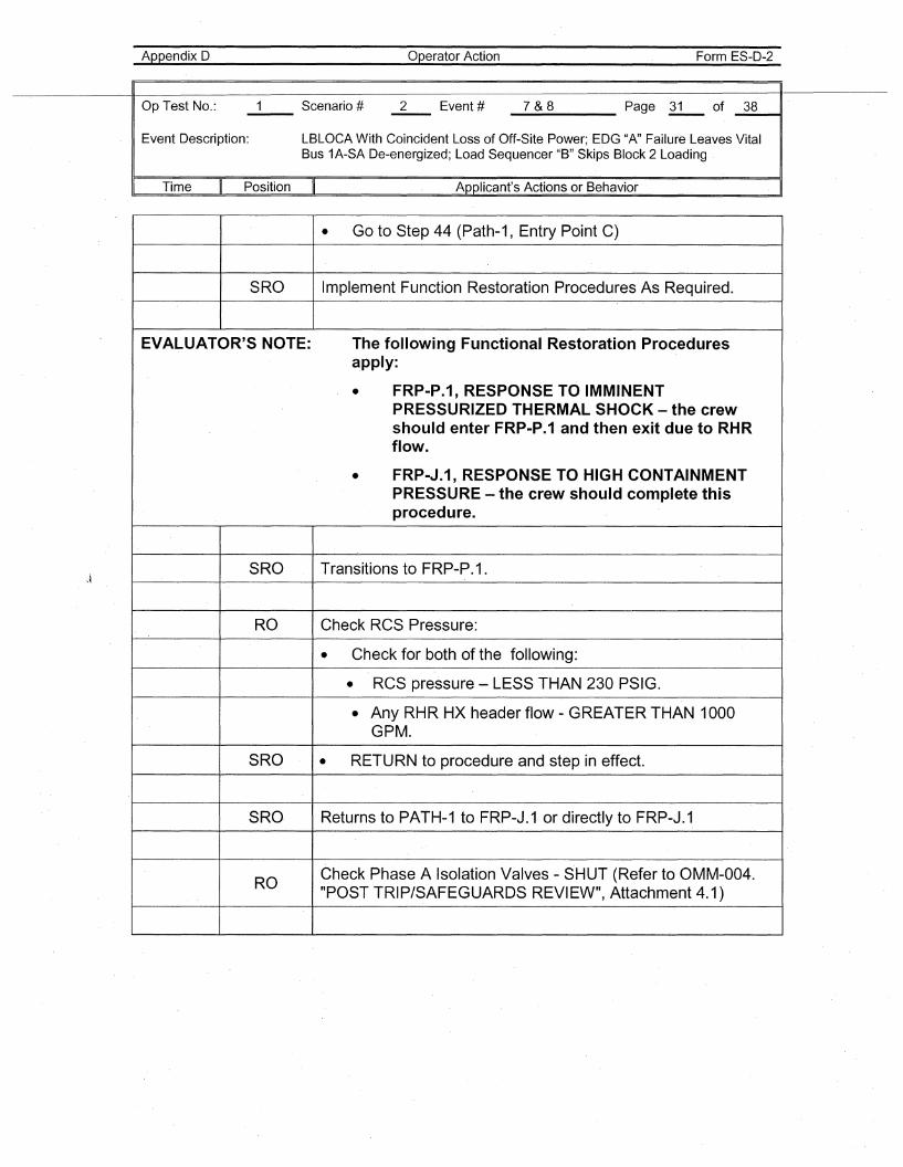
Appendix D Operator Action Form ES-D-2
Op Test No.: 1 Scenario # 2 Event # 7&8 Page 31 of 38
Event Description: LBLOCA With Coincident Loss of Off-Site Power; EDG "A" Failure Leaves VitalBus 1A-SA De-energized; Load Sequencer "B" Skips Block 2 Loading
I Time \I Position II Applicant's Actions or Behavior I
• Go to Step 44 (Path-1, Entry Point C)
SRO Implement Function Restoration Procedures As Required.
EVALUATOR'S NOTE: The following Functional Restoration Proceduresapply:
• FRP-P.1, RESPONSE TO IMMINENTPRESSURIZED THERMAL SHOCK - the crew'should enter FRP-P.1 and then exit due to RHRflow.
• FRP-J.1, RESPONSE TO HIGH CONTAINMENTPRESSURE - the crew should complete thisprocedure.
SRO Transitions to FRP-P.1.
RO Check RCS Pressure:
• Check for both of the following:
• RCS pressure - LESS THAN 230 PSIG.
• Any RHR HX header flow - GREATER THAN 1000GPM.
SRO • RETURN to procedure and step in effect.
SRO Returns to PATH-1 to FRP-J.1 or directly to FRP-J.1
ROCheck Phase A Isolation Valves - SHUT (Refer to OMM-004."POST TRIP/SAFEGUARDS REVIEW", Attachment 4.1)
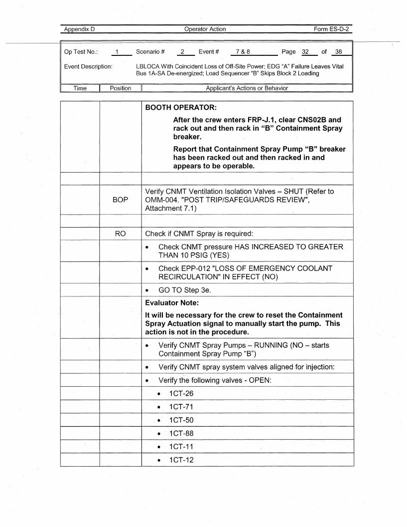
Appendix D
Op Test No.:
Operator Action Form ES-D-2
_7_&_8 Page ~ of _3_8__11
Event Desc~iption: LBLOCA With Coincident Loss of Off-Site Power; EDG "A" Failure Leaves VitalBus 1A-SA De-energized; Load Sequencer "B" Skips Block 2 Loading
" Time Position Applicant's Actions or Behavior
BOOTH OPERATOR:
After the crew enters FRP-J.1, clear CNS02B andrack out and then rack in "B" Containm'ent Spray'breaker.
Report that Containment Spray Pump "8" breakerhas been racked out and then racked in andappears to be operable.
Verify CNMT Ventilation Isolation Valves - SHUT (Refer toBOP OMM-004. "POST TRIP/SAFEGUARDS REVIEW",
Attachment 7.1)
RO Check if CNMT Spray is required:
• CheckCNMT pressure HAS INCREASED TO GREATERTHAN 10 PSIG (YES)
• Check EPP-012 "LOSS OF EMERGENCY COOLANTRECIRCULATION" IN EFFECT (NO)
• GO TO Step 3e.
Evaluator Note:
It will be necessary for the crew to reset the ContainmentSpray Actuation signal to manually start the pump. Thisaction is not in the procedure. ,
• Verify CNMT Spray Pumps - RUNNING (NO - startsContainment Spray Pump "B")
• Verify CNMT spray system valves aligned for injection:
• Verify the following valves - OPEN:
• 1CT-26
• 1CT-71
• 1CT-50
• ' 1CT-88
• 1CT-11
• 1CT-12
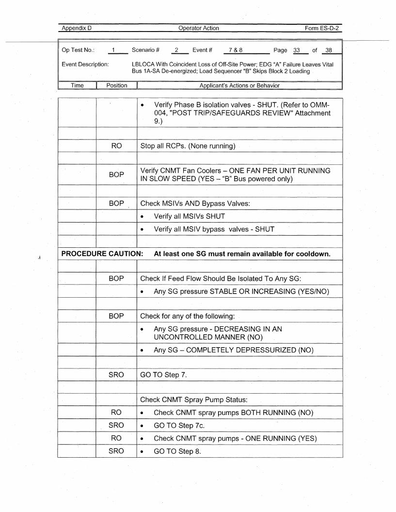
Appendix D
Op Test No.:
Operator Action Form ES-D-2
_7_&_8 Page ~ of _3_8----11
Event Description: LBLOCA With Coincident Loss of Off-Site Power; EDG "A"Failure Leaves VitalBus 1A-SA De-energized; Load Sequencer "B" Skips Block 2 Loading
Time Position Applicant's Actions or Behavior , I
• Verify Phas~ B, isolation valves - SHUT. (Refer to OMM-004, "POST TRIP/SAFEGUARD'S REVIEW" Attachment9.)
RO Stop all RCPs. (None running) ,
BOPVerify CNMT Fan Coolers - ONE FAN PER UNIT RUNNINGIN'SLOW SPEED (YES - "B" Bus powered only)
BOP Check MSIVs AND Bypass Valves:
• , Verify all MSIVs SHUT
• Verify all MSIV bypass valves - SHUT
PROCEDURE CAUTION: At least one SG must remain available for cooldown.
BOP Check If Feed Flow Should Be Isolated To Any SG:
• Any SG pressure STABLE OR INCREASING (YES/NO)
BOP Check for any of the following:
• Any SG pressure - DECREASING IN ANUNCONTROLLED MANNER (NO)
• Any SG -' COMp·LETELY DEPRESSURIZED (NO)
SRO GO TO Step 7.
Check CNMT Spray Pump Status:
RO • Check CNMT spray pumps BOTH RUNNING (NO)
S'RO • GO TO Step 7c.
RO • Check CNMT spray pumps - ONE RUNNING (YES)
SRO • GO TO Step 8.
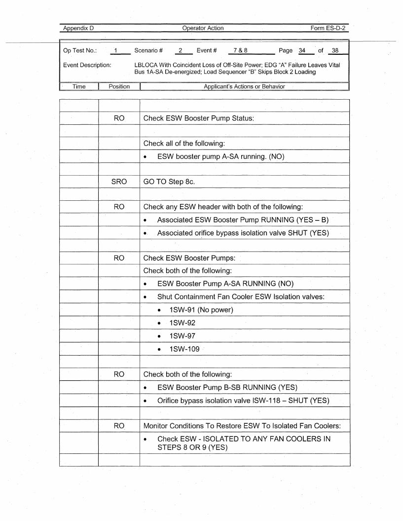
Appendix D
Op Test No.:
Operator Action Form ES-D-2
_7_&_8 Page 'li- of, _3_8__41
Event Description: LBLOCA With Coincident Loss of Off-Site Power; EDG "A" Failure Leaves VitalBus 1A-SA De-energized; Load Sequencer "B" Skips Block 2 Loading
,. Time Position II Applicant's Actions or Behavior
RO Check ESW Booster Pump Status:
Check all of the following:
• ESW booster pump A-SA running. (NO)
SRO GO TO Step '8c.
RO Check any ESW header with both of the following:
• AssoGiated ESW Booster Pump RUNNING (YES - B)., Associated or,ifice bypa,ss isolation valve SHUT (YES)
RO Check ESW Booster Pumps:
Check both of the following:
• ESW Booster Pump A-SA RUNNING (NO)
• Shut Containment Fan Cooler ESW Isolation valves:
• 1SW-91 (No power)
• 1SW-92
• 1SW-97
• 1SW-109
RO Check both of the following:
• ESW Booster Pump B-SB RUNNING (YES)
• Orifice bypass isolation valve I'SW-118 - SHUT (YES)
RO Monitor Con'ditions To Restore ESW To Isolated Fan Coolers:
• Check ESW -ISOLATED TO ANY FAN COOLERS INSTEPS 8 OR 9 (YES)
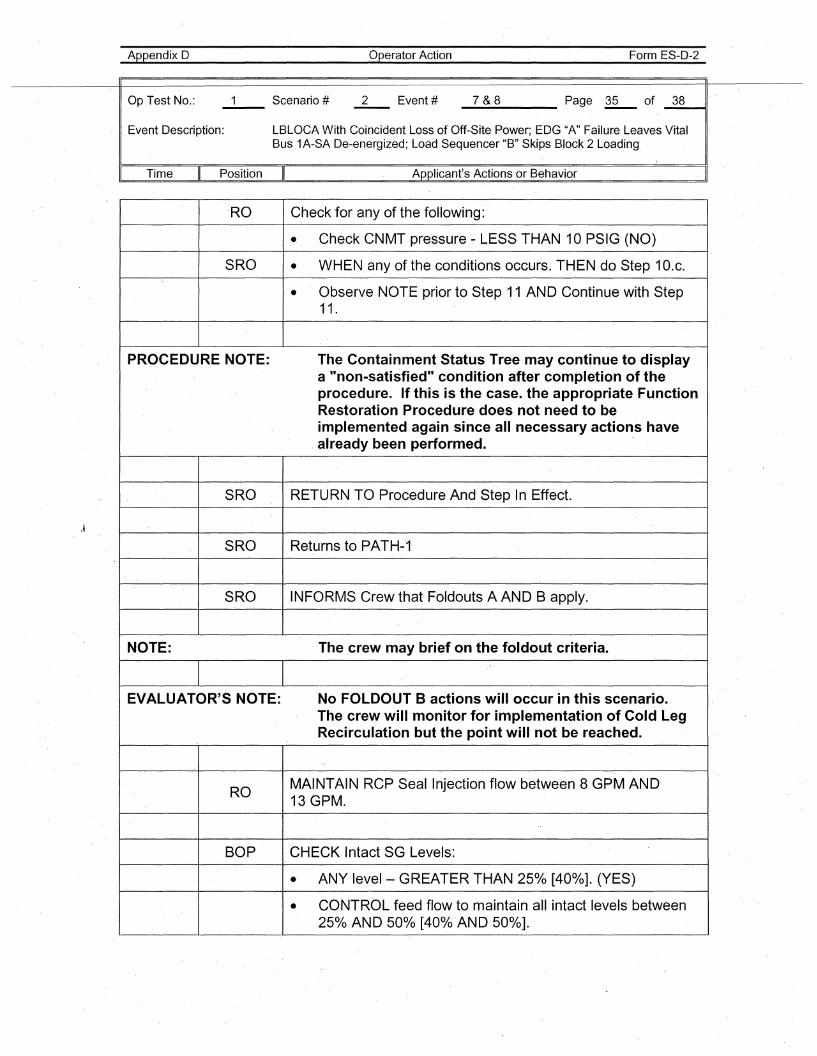
Appendix D Operator Action Form ES-D-2
Op Test No.: 1 Scenario # 2 Event # 7&8 Page '35 of 38
Event Description: LBLOCA With Coincident Loss of Off-Site Power; EDG "A" Failure Leaves VitalBus 1A-SA De-energized; Load Sequencer "B" Skips Block 2 Loading'
I Time II Position II Applicant's Actions or Behavior I
IRO Check for any of the following:
• Check CNMT pressure - LESS THAN 10 PSIG (NO)
SRO • WHEN any of the conditions occurs. THEN do Step 10.c.
• Observe NOTE prior to Step 11 AND Continue with Step11.
PROCEDURE NOTE: The Containment Statu's Tree may continue to displaya "non-satisfied" condition after completion of theprocedure. If this is the case. the appropriate FunctionRestoration Procedure does not need to beimplemen~ed again since all necessary actions have
, already been performed.
SRO RETURN TO Procedure And Step In Effect.
SRO Returns to PATH-1
SRO INFORMS Crew that· Foldouts A AND B apply.
NOTE: The crew may brief on the foldout criteria.
EVALUATOR'S NOTE: No FO·LDOUT B actions will occur in this scenario.The crew·will monitor for implementation of Cold LegRecirculation but the point will not be reached.
ROMAINTAIN RCP Seal Injection flow between 8 GPMAND13 GPM.
BOP CHECK Intact SG Levels:
• ANY level- GREATER THAN 25% [400/0]. (YE,S)
• CONTROL feed flow to maintain all intact levels between250/0 AND 50% [40% 'AND 500/0].
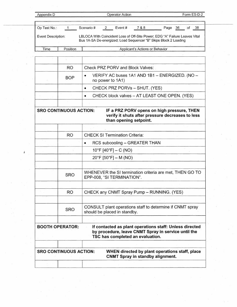
Appendix D Operator Action Form ES-D-2
Op Test No.: 1 Scenario # 2 Event # 7&8 Page 36 of 38
Event Description: LBLOCA With Coincident Loss of Off-Site Power; EDG "A" Failure Leaves VitalBus 1A-SA De-energized; Load Sequencer "B" Skips Block 2 Loading
I. Time II Position II Applicant's Actions or Behavior I
RO Check PRZ PORV and .BlockValves:
BOP • VERIFY AC buses 1A1 AND 1B1 - ENERGIZED. (NO-no power to 1A1)
• CHECK PRZ PORVs - SHUT. (YES)
• CHECK block valves - AT LEAST ONE OPEN. (YES)
SRO CONTINUOUS ACTION: IF a PRZPORV opens on high pressure, THENverify it shuts after pressure decreases to lessthan opening setpoint.
RO CHECK 81 Termination Criteria:
• RCS subcooling - GREATER THAN
10°F [40°F] - C .(NO)
20°F [50°F] - M (NO)
SROWHENEVER the SI termination criteria are met, THEN GO TOEPP-008, "SI TERMINATION".
RO CHECK any CNMT Spray Pump - RUNNING. (YES)
SROCONSU·LT plant operations staff to determine if CNMT spray.should be placed in standby.
. BOOTH OPERATOR: If contacted as plant operations staff: Unless directedby procedure, leave CNMT Spray in service until the·TSC has completed an evaluation.
SRO CONTINUOUS ACTION: WHEN directed by plant operations staff, placeCNMT Spray in standby alignment.
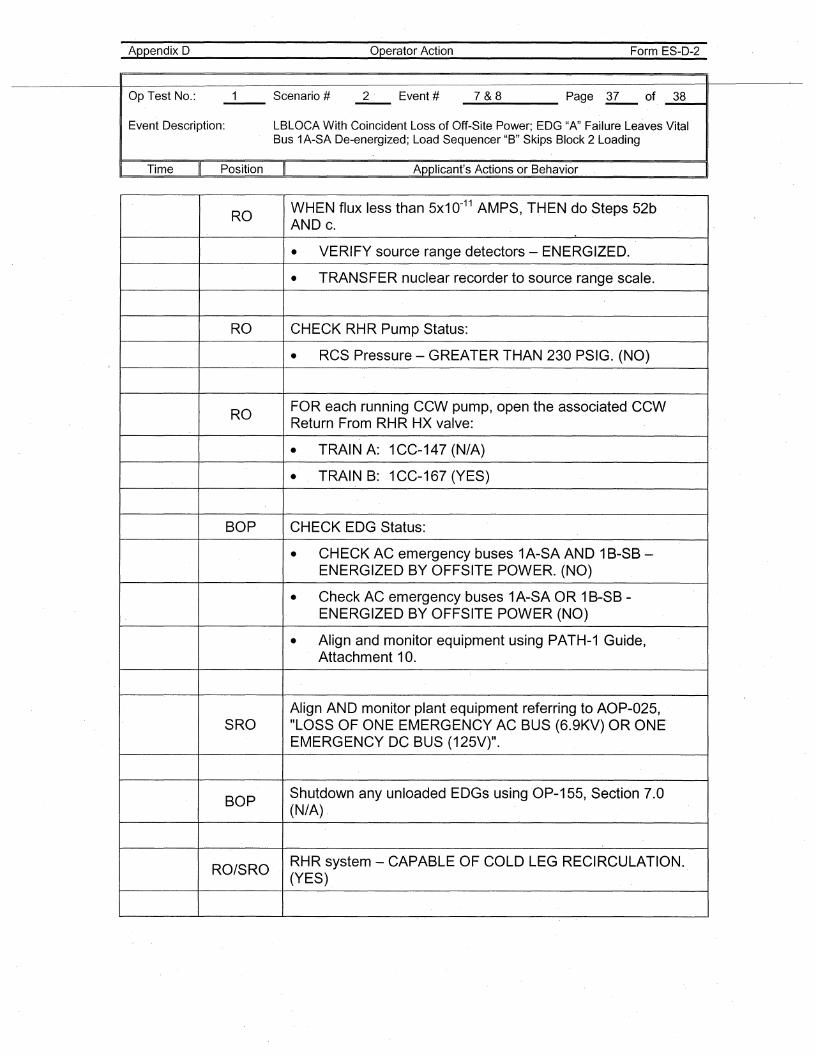
Appendix D Operator Action Form ES-D-2
Op Test No.: 1 Scenario # 2 Event # 7&8 Page 37 of 38
Event Description: LBLOCA With Coincident Loss of Off-Site Power; EDG "A" Failure Leaves VitalBus 1A-SA De-energized; Load Sequencer "B" Skips Block 2 Loading
I Time II Position II Applicant's Actions or Behavior I
ROWHEN flux less than 5x10-11 AMPS, THEN ,do Steps 52bAND c.
• VERIFY source range detectors - ENERGIZED.
• TRANSFER nuclear recorder to source range scale.
RO CHECK RHR Pump Status:
• RCS Pressure - GREATER THAN 230 PSIG. (NO)
ROFOR each running CCW pump, open the associated CCWReturn From RHR HX valve:
• TRAIN A: 1CC-147 (N/A)
• TRAIN B: 1CC-167 (YES)
BOP CHECK EDG Status:
• CHECK AC emergency buses 1A-SA AND 1B-SB-ENERGIZED BY OFFSITE POWER. (NO)
• Check AC emergency buses 1A-SA OR 1B-SB-ENERGIZED BY OFFSITE POWER (NO)
• Align and monitor equipment using PATH-1 Guide,Attachment 10.
Align AND monitor plant equipment referring to AOP-025,SRO "LOSS OF ONE EMERGENCY AC BUS (6.9KV) OR ONE
EMERGENCY DC BUS (125V)".
BOPShutdown any unloaded EDGs usingOP-155, Section 7.'0(N/A) ,
RO/SRORHR system - CAPABLE OF COLD LEG RECIRCULATION.(YES)
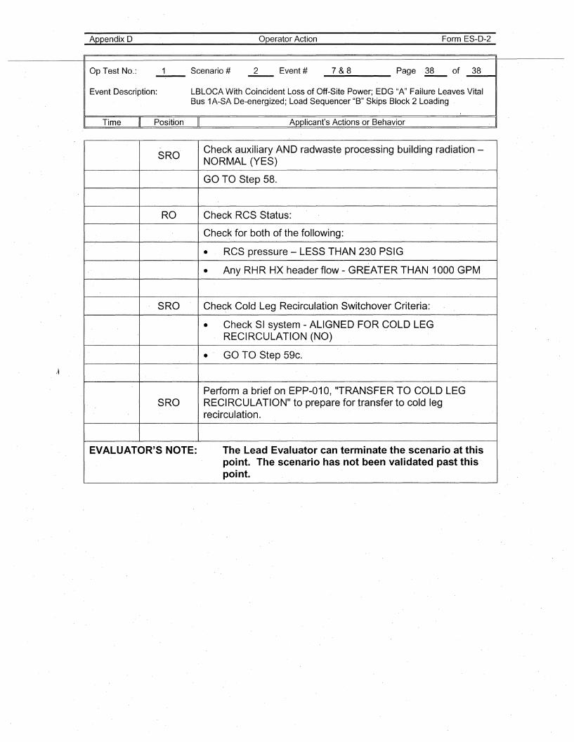
Appendix D Operator Action Form ES-D-2
\~
Op Test No.: 1 Scenario # 2 Event # 7&8 Page 38 of 38
Event Description: LBLOCA With Coincident Loss of Off-Site Power; EDG "A" Failure Leaves VitalBus 1A-SA De-energized; Load Sequencer "B" Skips Block 2 Loading
I Time
"
Position II Applicant's Actions or Behavior . I
SROCheck auxiliary AND radwaste processing building radiation -NORMAL (YES)
GO TO Step 58.
RO Check RCS Status:
Check for both of the following:
• RCS pressure - LESS T·HAN 230 PSIG
• Any RHRHX header flow - GREATER THAN 1000 GPM
SRO Check Cold Leg Recirculation Switchover Criteria:
• Check SI system - ALIGNED FOR COLD LEGRECIRCULATION (NO)
• GO TO Step 59c.
Perform a brief on EPP-010, "TRANSFER TO COLD LEGSRO RECIRCULATION" to prepare for transfer to cold leg
recirculation.
EVALUATOR'S NOTE: The Lead Evaluator can terminate the.scenario at thispoint. The scenario has not been validated past thispoint.
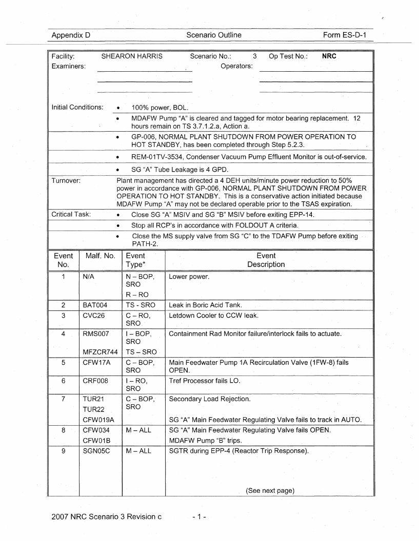
Appendix D Scenario Outline Form ES-D-1
Facility: SHEARON HARRIS Scenario No.: 3 Op Test No.:' NRC.
Examiners: Operators:
Initial Conditions: • 1000/0 power, BOL.
• MDAFW Pum'p "A" is cleared and tagged for motor bearing replacement. 12hours remain on TS 3.7.1.2.a, Action a. .
• GP-006, NORMAL PLANT SHUTDOWN FROM POWER OPERATION TOHOT STANDBY, has been completed through Step 5.2.3~
• REM-01TV-3534, Condenser Vacuum Pump Effluent Monitor is out-of-servic-e.
• SG "A" Tube Leakage is 4 GPD.
Turnover: Plant management has directed a 4 DEH units/minute power reduction to 50%power in accordance with·GP-Q06, NORMAL PLANT SHUTDOWN FROM POWEROPERATION TO HOT STA·NDBY. This is a conservative action initiated becauseMDAFW Pump "A" may not be declared operable prior to the TSAS expiration.
Critical Task: • Close SG "A" MSIV and SG"B" MSIV before exiting EPP-14.
• Stop all RCP's in accordance with FOLDOUT A criteria.
• Close the MS supply valve from SG "C" to the TDAFW Pump before exitingPATH~2.
Event Malf. No. Event EventNo. Type* Description
1 N/A N - BOP, Lower power.SRO
R-RO
2 BAT004 TS - SRO Leak in' .Boric Acid Tank.
3 CVC26 C-RO, Letdown Cooler to CCW leak.SRO
4 RMS007 I-BOP, Containment Rad Monitor failure/interlock fails to actuate.SRO
MFZCR744 TS-SRO
5 .CFW17A C - BOP, Main Feedwater Pump 1A Recirculation Valve (1 FW-8) failsSRO OPEN.
6 CRF008 I-RO, Tref Processor fails LO.SRO
7 TUR21 C. - BOP, Secondary Load Rejection.
TUR22 SRO
CFW019A SG "A" Main Feedwater Regulating Valve fails to track in AUTO.
8 CFW034 M-ALL SG "A" Main Feedwater Regulating Valve fails OPEN.
CFW01B MDAF.W Pump "B" trips.
9 SGN05C M-ALL SGTR during EPP-4 (Reactor Trip Response).
(See next -page)
2007 'NRC Scenario 3 Revision c - 1 -
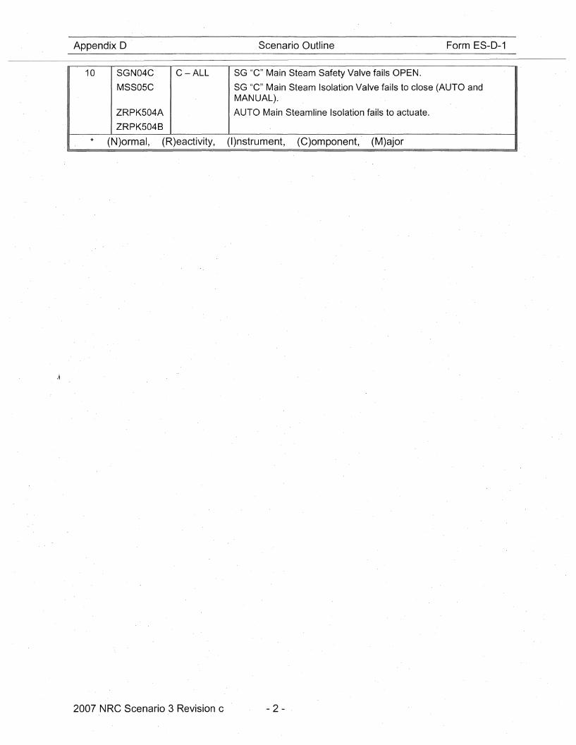
Appendix D Scenario Outline Form ES-D-1
10 SGN04C
MSS05C
ZRPK504A
ZRPK504B
C-ALL SG "C"Main Steam Safety Valve fails O·PEN.
SG "C" Main Steam Isolation Valve fails to close (AUTO andMANUAL).
AUTO Main Steamline Isolation faBs to actuate.
* (N)ormal, (R)eactivity, (I)nstrument, (C)omponent,. (M)ajor
2007 NRC Scenario 3 Revision c .- 2 -
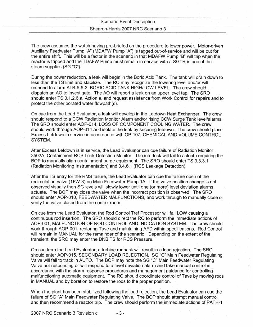
Scenario Event Description
Shearon-Harris 2007 NRC Scenario 3
The crew assumes the watch having, pre-briefed on the procedure to lower power. Motor-drivenAuxiliary Feedwater Pump "A" (MDAFW Pump "A") is tagged out-of-service and will be out forthe ,entire shift. This will be a factor in the scenario in that MDAFW Pump "B" will trip when thereactor is tripped and the TDAFW Pump must remain in service with a SGTR in one of thesteam supplies (SG "C").
During the power reduction, a leak will begin in the Boric Acid Tank. The tank will drain down toless than the TS'limit and stabilize. The RO may recognize the lowering level and/or willrespond to alarm ALB-6-6-3, BORIC ACID TANK HIGH/LOW LEVEL. The crew should'dispatch an AO to investigate. The AO will report a leak on an upper level tap. The SROshould enter TS 3.1.2.6.a, Action a. and request assistance from Work Control for repairs and toprotect the other borated water flowpath(s).
On cue from the Lead Evaluator, a leak wiH develop in the Letdown Heat Exchanger. The crewshould respond to a CCW Radiation Monitor 'Alarm and/or rising CCW Surge Tank level/alarms.The SRO should enter AOP-014, LOSS OF COMPONENT COOLING WATER. The crewshould work through AOP-014 and isolate the leak by securing letdown. The crew should placeExcess Letdown in service in accordance with OP-107, CHEMICAL AND VOLUME CONTROLSYSTEM.
After Excess Letdown' is in service, the Lead Evaluator can cue failure of Radiation Monitor,3502A, Containment RCS Leak Detection Monitor. The interlock will fail to actuate requiring theBOP to manually align containment purge equipment. The SRO should enter TS 3.3.3.1(Radiation Monitoring Instrumentation) and 3.4.6.1 (RCS Leakage Detection).
After the TS entry for the RMS failure, the Lead Evaluator can cue the failure open of therecirculation valve (1 FW-8) on Main Feedwater Pump 1A. If the valve position change is notobserved visually then SG levels will slowly lower until one (or more) level deviation alarms,actuate. The BOP may close the valve when the incorrect position is observed. The SROshould enter AOP-010, FEEDWATER, MALFUNCTIONS, and work through to manually close orverify the valve closed from the control room.
On cue from the Lead Evaluator, the Rod Control Tref Processor will fail LOW causing acontinuous rod insertion. The 'SRO should direct the RO to perform the immediate actions ofAOP-001, MALFUNCTION OF ROD CONTROL AND INDICATION SYSTEM. The crew shouldwork through AOP-001; restoring Tave and maintaining AFD within specifications. Rod' Controlwill remain in MANUAL for the remainder of the ,scenario. Depending on the extent 'of thetransient, the SRO may enter the DNB TS for RCS Pressure.
On cue from the Lead Evaluator, a turbine runback will result in a load rejection. The ,·SROshould enter'AOP-015, SECONDARY LOAD REJECTION. SG,"C" Main Feedwater Regul'atingValve 'will fail to track in AUTO. The BOP may note the SG "c" M,ain Feedwater RegulatingValve not responding, or will respond to a level deviation alarm and take manual control inaccordance with the alarm response procedures and management guidance for controllingmalfunctioning automatic equipment. The RO should coordinate control of Tave by moving rodsin MANUAL and by boration to restore the rods to the proper position. '
When the plant has been stabilized following the load rejection, the Lead 'Evaluator can cue thefailure of SG "A" Main Feedwater Regulating Valve. The BOP should attempt manual controland then recommend a reactor trip. The crew should perform the immediate actions of PATH-1
2007 NRC Scenario 3 Revision c - 3 -
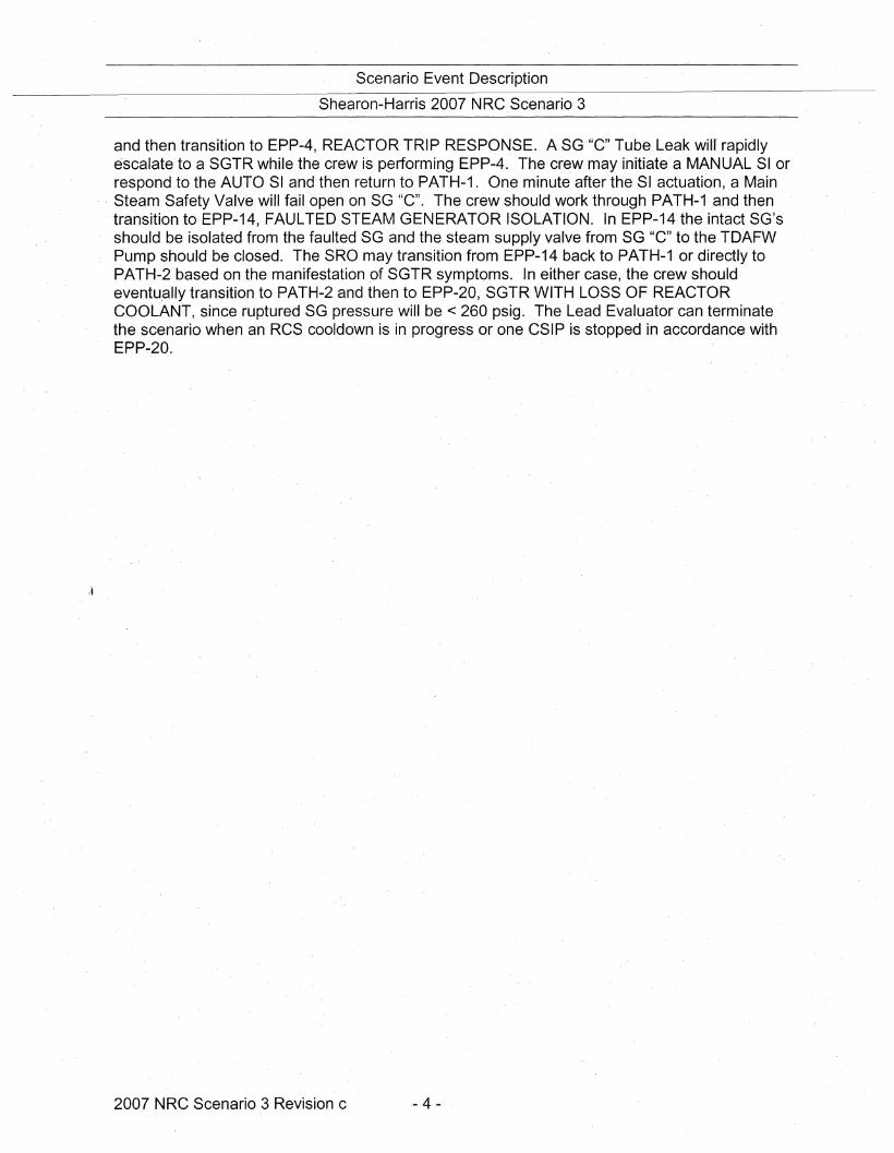
Scenario ,Event Description
Shearon-Harris 2007 NRC Scenario 3
and then transition to EPP-4, REACTOR TRIP RESPONSE. A SG'''C'' Tube Leak will' rapidlyescalate to a SGTR while the crew is performing EPP-4. The crew may initiate a MANUAL SI orrespond to the AUTO SI and then return to PATH-1. One minute after the SI actuation, a Main
, Steam Safety Valve will fail open on SG "e". The crew should work through PATH-1 and thentransition to EPP-14, FAULTED STEAM GENERATOR ISOLATION. In EPP-14 the intact SG'sshould be isolated from the faulted SG and the steam supply valve from SG "C" to the TDAFWPump should be closed. The SRO may transition from EPP-14 back to PATH-1 or directly toPATH-2 based on the manifestation of SGTR symptoms. In either case, the crew shouldeventu.ally transition to PATH-2 and then to EPP-20, SGTR WITH LOSS OF REACTORCOOLANT, since ruptured SG pressure will be < 260 psig. The Lead Evaluator 'can terminatethe scenario when an RCS cooldown is in progress or one CSIP is stopped in accordance withEPP-20.
200,7 NRC Scenario 3 Revision c ,- 4 -
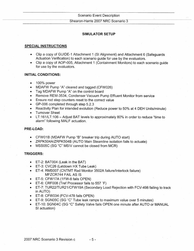
Scenario Event Description
Shearon-Harns 2007 NRC Scenano 3
SIMULATOR SETUP
SPECIAL INSTRUCTIONS
• Clip a copy of GUIDE-1 Attachment 1 (SI Alignment) and Attachment 6 (SafeguardsActuation Verification) to each scenario guide for use by the evaluators.
• Clip a copy of AOP-005, Attachment 1 (Containment Monitors) to each scenario guidefor use by the· evaluators.
INITIAL CONDITIONS:
• 1000/0 power• MDAFW Pump "A" cleared and tagged (CFW026)• Tag MDAFW Pump "A" on the control board• Remove REM-3534, Condenser Vacuum Pump Effluent Monitor from service• Ensure rod step counters reset to the correct value• GP-006 completed through step 5.2.3• Reactivity Plan for intended evolution (Reduce power to 500/0 at 4 DEH Units/minute)• Turnover Sheet• LT:161/LT:106 - Adjust ·BAT levels to approximately 80% in order to reduce "time to'
alarm" following MALF actuation.
PRE-LOAD:
• CFW01 B (MDAFW Pump "B" breaker trip during AUTO start)• ZRPK504A1ZRPK504B (AUTO Main Steam.line isolation fails to actuate)• MSS05C (SG "C" MSIV cannot be closed from MCR)
TRIGGERS:
• ET-2: BAT004 (Leak in the BAT)• ET-3: CVC26 (Letdown HX Tube Leak)• ET-4: RMS007 (CNTMT Rad Monitor 3502A failure/lnterlock failure)
MFZCR744 FAIL AS IS• ET-5: CFW17A (1 FW-8 fails OPEN)• ET-6: CRF008 (Tref Processor fails to 557 OF)• ET-7: TUR22ITUR21/CFW19A (Secondary Load Rejection with FCV-498 failing to track
in AU.TO)• ET-8: CFW034 (FCV-478 fails OPEN)• ET-9: SGN05C (SG "C" Tu·be leak ramps to maximum value over 5 minutes)• ET-10: SGN04C (SG "C" Safety Valve fails OPEN one minute after AUTO or MANUAL
SI actuation)
2007 NRC Scenario 3 Revision c - 5 -
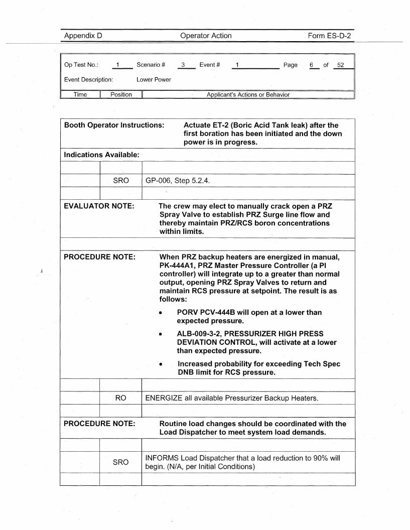
Appendix D Operator Action Form ES-D-2
Op Test No.:
Event Description: Lower Power
_____ Page 6 of' _5_2~,
Time Position Applicant's Actions or Behavior
Booth Operator Instructions:
Indications Available:
Actuate ET-2 (Boric Acid Tank leak) after thefirst boration has been initiated and the downpower is in progress.
SRO . GP-006, Step 5.2.4.
EVALUATOR NOTE: The crew may elect to manually crack open a PRZSpray Valve to establish PRZ Surge line flow andthereby maintain PRZ/RCS boron concentrationswithin limits.
PROCEDURE NOTE:
RO
PROCEDURE NOTE:
SRO
When PRZ backup heaters are energized in manual,PK-444A1, PRZ Master Pressure Controller (a ,PIcontroller) will 'integrate up to a greater than normaloutput, opening PRZ Spray Valves to return andmaintain RCS pressure at setpoint. The result is asfollows:
• PORV PCV-444B will open at a lower thanexpected pressure.
• ALB-009-3-2, PRESSURIZER HIGH PRESSDEVIATION CONTROL, will activate at a lowerthan expected pressure.
• Increased probability for exceeding Tech SpecDNB limit for RCS pressure.
ENERGIZE all available Pressurizer Backup Heaters.
Routine load changes should be coordinated with theLoad Dispatcher to meet system load demands~
I,NFORMS Load, Dispatcher that a load reduction to 90% willbegin. (N/A, per Initial Conditions)
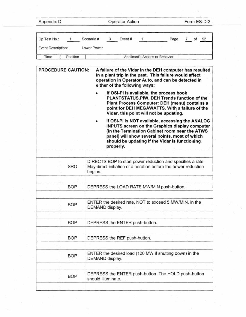
Appendix D Operator Action Form ES-D-2
Op'Test No.: Scenario # 3 Event #-- '-- _____ Page 7 of _5_2--11
Event Description: Lower Power
I' Time Position Applicant's Actions or Behavior
PROCEDURE CAUTION: A failure of the Vidar in the DEH computer has resultedin a plant trip in the past. This failure would affectoperation in Operator Auto, and can be detected ineither of the following ways:
• If OSI-PI is available, the process bookPLANTSTATUS.PIW, DEH Trends function of thePlant Process Computer: DEH (menu) contains apoint for DEH MEGAWATTS. With a failure of theVidar, this point will not ,be updating.
• If OSI-PI is NOT available, accessing the ANALOG,INPUTS screen on the Graphics display computer(in the Termination Cabinet room near the, ATWSpanel) will show several points, most of which'should be updating if the Vidar is functioningproperly.
DIRECTS BOP to start power reduction and specifies a rate.SRO May direct initiation of a boration before the power reduction,
begins.'
BOP DEPRESS the LOAD RATE MW/MIN push-button.
BOPENTER the desired rate, NOT to exceed 5 MW/MIN, in theDEMAND display.
BOP DEPRESS the ENT,ER push-button.
BOP' DEPRESS the REF push-button.
BOPENTER the desired load (120 MW if shutting down) in theDEMAND display.
BOPDEPRESS the ENTER push-button. The H'OLD push-buttonshould illuminate.

Appendix D Operator Action Form ES-D-2
Op Test No.:
Event Description: Lower Power
_____ Page 8 of· _5_2~,
I Time Position Applicant's Actions or Behavior
\~
PROCEDURE NOTE: The unloading of the unit can be stopped at any timeby depressing the. HOLD push-button. The HOLD lampwill illuminate and the GO lamp will extinguish. Theload reduction can be resumed by depressing· the GOp.ush-button. The HOLD lamp will extinguish and theGO lamp will illuminate.
BOP DEPRESS the GO push-button to start.the load reduction.
BOP VERIFY the number in the REFERENCE display decreases.
BOP VERIFY Generator load is decreasing.
WHEN Turbine load is less than 950/0, THEN VERIFY.the 3ABOP and 38 Feedwater Vents have been opened per OP-136,
Section 7.2.
SIMULATOR OPERATOR: Acknowledge direction. No simulator responseactions are required.
RO MONITORS pri·mary systems response.
RO INITIATES boration, as necessary (with SRO concurrence).
NOTE: OP-107 is.a "Reference Use" procedure.
RODETERMINE the reactor coolant boron concentration fromchemistry OR the Main Control Room status board.
RODETERMINE the magnitude of boron concentration increaserequired.
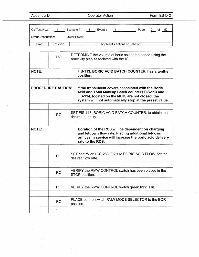
Appendix D Operator Action Form ES-D-2
Op·Test No.: Scenario # 3 Event #-- ._- _____ Page. 9 .of _5_2__"41
Event Description: Lower Power
,. Time Position Applicant's Actions or Behavior
RODETERMINE the volume of boric acid to be added using thereactivity plan associated with the ·IC.
NOTE: FIS-113, BORIC ACID BATCH COUNTER, has a tenthsposition.
PROCEDURE CAUTION: If the translucent covers associated with the BoricAcid and Total Makeup Batch ·counters FIS-113 andFIS-114, located on the MCB, are not closed, thesystem will not automatically .stop at the preset value.
ROS.ET FIS-113, BORIC ACID BATCH COUNTER, to obtain thedesired quantity.
NOTE: Boration of the RCS will be dependent on chargingand letdow·n flow rate. Placing additional letdownorifices in service will increase the boric acid deliveryrate to the RCS.
ROSET controller 1CS-283, FK-113 BORIC ACID FLOW, forthedesired flow rate.
ROVERIFY the RMW CONTROL switch has been placed in theSTOP position.
RO VERIFY the RMW CONTROL switch green light is lit.
ROPLAC.E control switch RMW MODE SELECTOR to the BORposition..
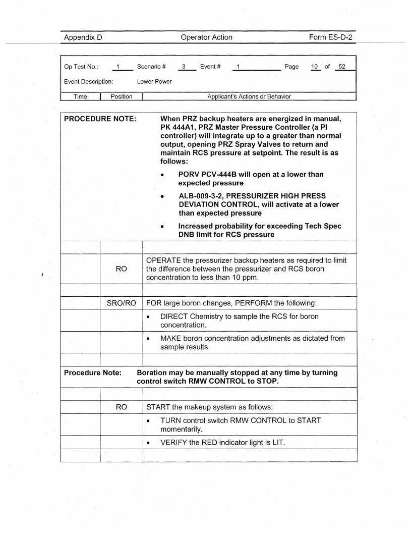
Appendix D Operator Action Form ES-D-2
Op Test No.:
Event Description:
I Time II' Position
Lower Power
_____ Page 10 of _5_2----41
Applicant's Actions or Behavior
PROCEDURE NOTE:
RO
When PRZ backup heaters are. energized in manual,PK 444A1, PRZ Master Pressure Controller (a PIcontroller) will integrate up to a greater than normaloutput, opening PRZ Spray Valves to return andmaintain RCS pressure at setpoint. The result is asfollows:
• PORV PCV-444B will open at a lower thanexpected pressure
• ALB-009-3-2, PRESSURIZER HIGH PRESSDEVIATION CONTROL, will activate at a lowerthan expected pressure
• Increased probability for exceeding Tech SpecONB limit for RCSpressure
OPERATE the pressurizer backup heaters as required to limitthe difference between the pressurizer and RCS boronconcentration to less than 10 ppm.
SRO/RO FOR large boron changes, PERFORM the following:
• DIRECT Chemistry to sample the RCS for boronconcentratio·n.
• MAKE boron concentration' adjustments as dictated from'sample results.
Procedure Note: Borationmay be manually stopped at any time by turningcontrol switch RMW CONTROL to STOP.
RO START. the makeup system as follows:
• TURN control switch RMW CONTROL to STARTmomentarily.
. • VERIFY the RED indicator light is LIT.
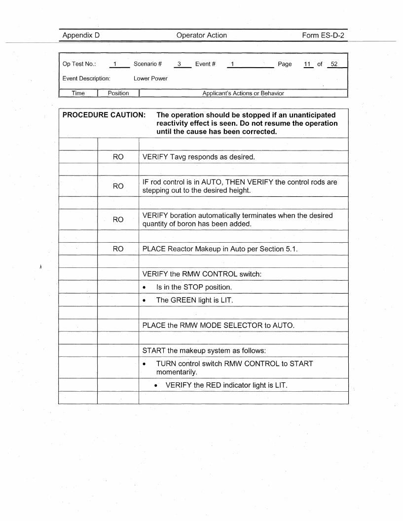
Appendix D Operator Action Form ES-D-2
Op Test No.:
Event Description: Lower Power
_____ Page 11 of _5_2---11
I Time Position Applicant's Actions or Behavior
PROCEDURE CAUTION: The operation'should be stopped if an unanticipatedreactivity effect is. seen. Do not resume the operationuntil the cause has been corrected.
RO VERIFY Tavg responds as desired.
ROIF rod control is in AUTO, THEN VERIFY the control rods arestepping out to the desired height.
ROVERIFY boration automatically terminates when the desired'quantity of boron has been added.
RO PLACE Reactor Makeup in Auto per Section 5.1.
VERIFY the RMW CONTROL switch:
• Is in the STOP position.
• The GREEN light is LIT.
PLACE the RMW MODE SELECTOR to AUTO.
START the makeup system as follows:
• TURN control switch RMW CONTROL to STARTmomentarily.
• VERIFY the RED indicator light is LIT.
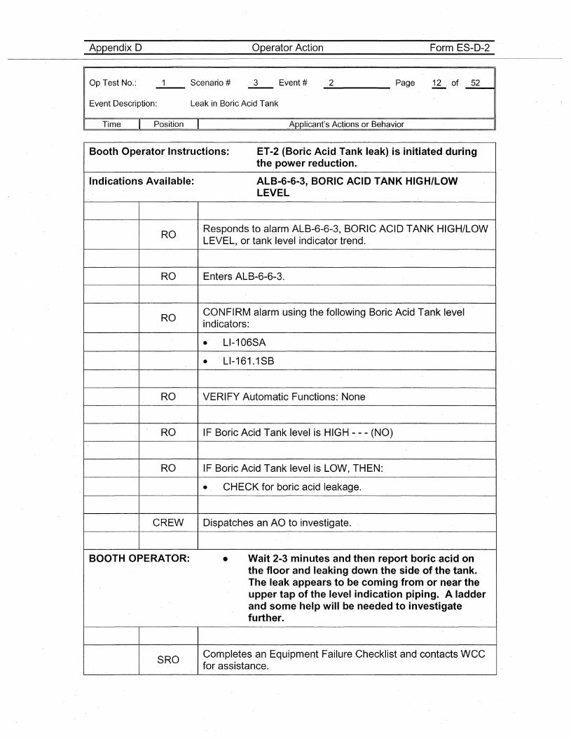
Appendix D Operator Action Form ES-D-2
Op.Test No.:
Event Description: Leak in Boric Acid Tank
_2_____ Page 12 of. _5_2---11
. Time Position Applicant's Actions or Behavior
Booth Operator Instructions: ET-2 (Boric Acid Tank leak) is initiated duringthe power reduction.
Indications Available: ALB-6-6-3, BORIC ACID TANK HIGH/LOWLEVEL
ROResponds to alarm ALB-6-6-3, BORIC. ACID TANK HIGH/LOWLEVEL, or tank level indicator trend.
RO Enters ALB-6-6-3.
ROCONFIRM alarm using the following Boric Acid Tank levelindicators:
• LI-106SA
• LI-161.1SB
RO VERIFY Automatic Functions: None
RO IF Boric Acid Tank level is HIGH - - - (NO)
RO IF Boric Acid Tank level is LOW, THEN:
• CHECK for boric acid leakage.
CREW Dispatches an AO to investigate.
BOOTH OPERATOR: • Wait 2·3 minutes and then report boric acid onthe floor and leaking down the side of the tank.The leak appears to be coming from or near theupper tap of the level indication piping. A ladderand some help will be needed to investigatefurther.
SROCompletes an Equipment Failure Checklist and contacts WCCfor assistance.
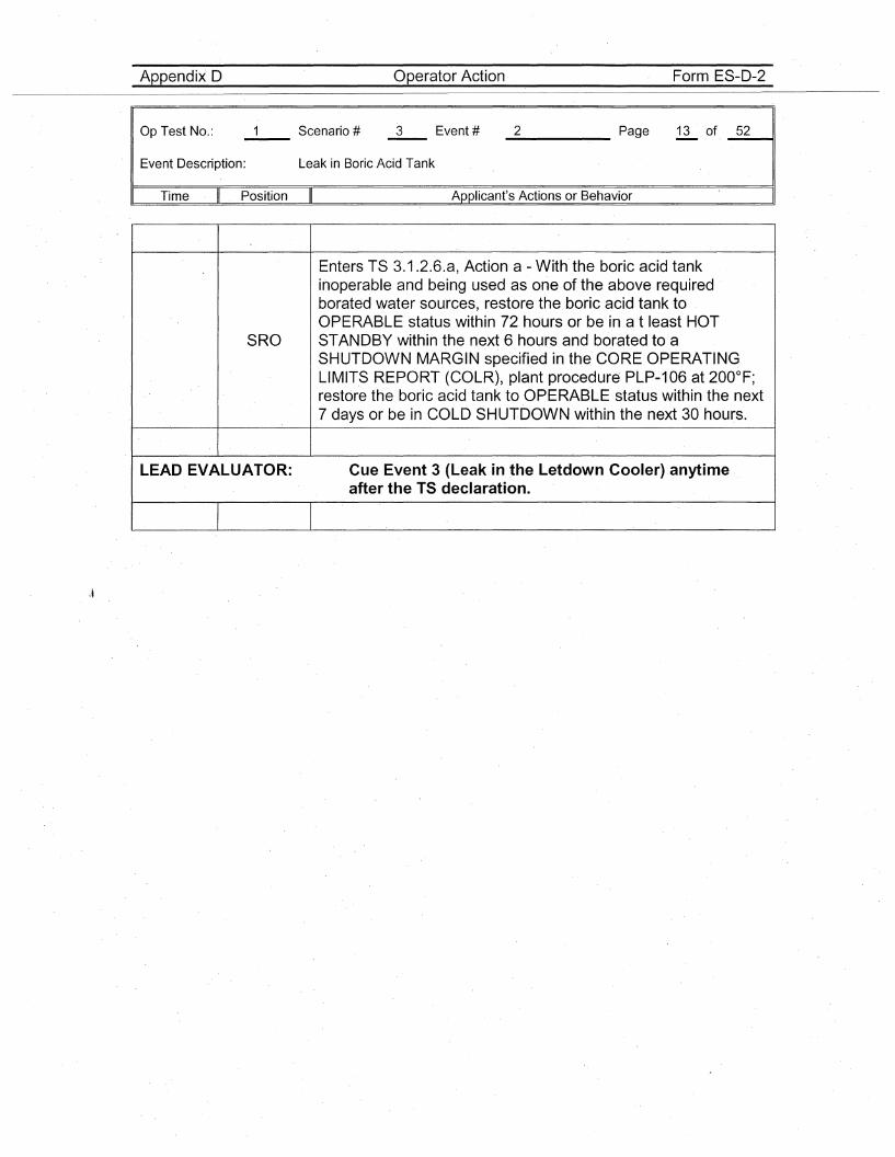
Appendix D Operator Action Form ES-D-2
Op Test No.:
Event Description: Leak in Boric Acid Tank
_2 Page 13 of _5_2---41
Time Position Applicant's Actions or Behavior
\~
Enters TS 3.1.2.6.a, Action a - With the boric acid tankinoperable and being used as one of the above requiredborated water sources, restore the boric acid tank toOPERABLE status within 72 hours or be in a t least HOT
SRO STANDBY within the next 6 hours and borated to aSHUTDOWN MARGIN specified in the CORE OPERATINGLIMITS REPORT (COLR), plant procedure PLP-106 at 200°F;restore the boric acid tank to OPERABLE status within the next7 days or be in COLD SHUTDOWN within the next 30 hours.
LEAD EVALUATOR: Cue Event 3 (Leak in the Letdown Cooler) anytimeafter the TS declaration.
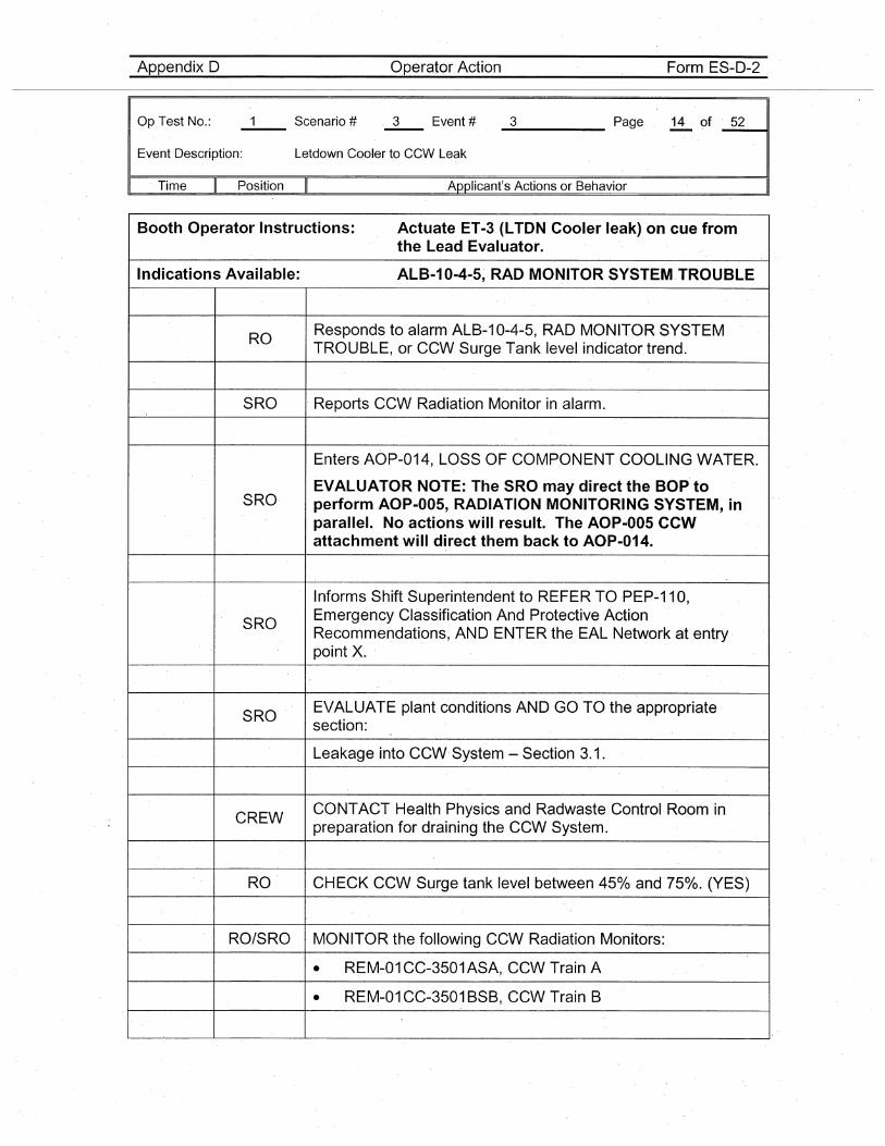
Appendix D Operator Action Form ES-D-2
Op.Test No.:
Event Description: Letdown Cooler to CCW Leak
_3 Page 14 of· _5_2----11
. Time Position Applicant's Actions or Behavior
Booth Operator Instructions: Actuate ET-3 (LTDN Cooler leak) on cue fromthe Lead Evaluator.
Indications Available: ALB-10-4-5, RAD MONITOR SYSTEM.TROUBLE
ROResponds to alarm ALB-10-4-5~ RAD MONITOR SYSTEMTROUBLE, or CCW Surge Tank level indicator trend.
SRO Reports CCW Radiation Monitor in alarm.
Enters AOP-014, LOSS OF COMP.ONENT COOLING WATER.
SRO·EVALUATOR NOTE: The SRO may direct the BOP' toperform AOP-005, RADIATION MONITORING SYSTEM,inparallel. No actions will res·ult. The AOP-005 CCWattachment will direct them back to AOP-014.
Informs Shift Superintendent to REFER TO PEP-11O,
SROEmergency Classification And Protective ActionRecommendations, AND ENTER the EAL Network at entrypoint X.
SROEVALUATE plant conditions AND GO TO the appropriatesection:
Leakage into CCW'System - Section 3.1.
CREWCONTACT Health Physics and Radwaste Control Room inpreparation for draining the CCW System.
RO CHECK CCW Surge tank level between 450/0 and 750/0. (YES)
RO/SRO MONITOR the following CCWRadiation Monitors:
• REM-01CC-3501ASA, CCW Train A
• REM-01 CC-3501 BSB; CCWTrain B
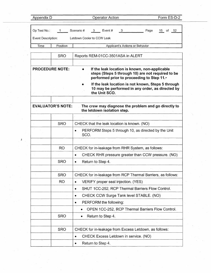
Appendix 0 Operator Action Form ES-D-2
Op Test No.:
Event Description: Letdown Cooler to CCW Leak.
_3 Page 15 of _5_2--11
Time Position Applicant's Actions or Behavior
SRO Reports REM-01CC-3501ASA in ALERT
PROCEDURE NOTE: • If the leak location is known, non-applicablesteps (Steps 5 through 10) are not required to beperformed prior to proceeding to Step 11.-
• If the leak location is not known, Steps 5 through10 may be performed in any order, as' directed bythe Unit SCO.
EVALUATOR'S' NOTE: The crew may diagnose the problem and go directly tothe letdown isolation step.
SRO CHECK that the leak location is known. (NO)
• PERFORM Steps 5 through 10, as directed by the UnitSCO.
RO CHECK for in-leakage from RHR System, as follows:
• CHECK RHR pressure greater than CCW pressure. (NO)
S'RO • Return to Step 4.
SRO CHECK for in-leakage from RCP Thermal Barriers, as follows:
RO • VERIFY proper seal injection. (YES)
• SHUT 1CC-252,RCP Therm'al Barriers Flow Control.
• CHECK CCW Surge Tank level STABLE. (NO) ,
• PERFORM the following:
• 'OPEN 1CC-252, RCP Thermal Barriers Flow Control.
SRO • Return to Step 4.
SRO CHECK for in-leakage from, Excess Letdown, as follows:
• CHECK Excess Letdown in service. (NO)
.. Return to Step 4.
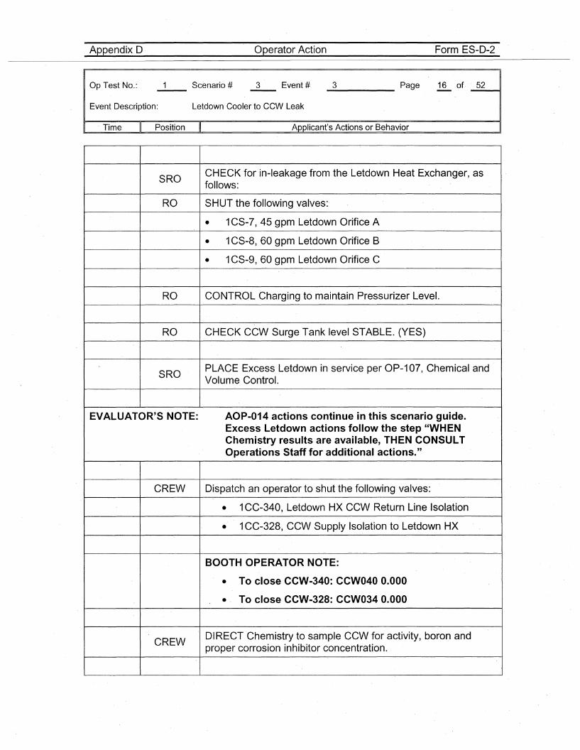
Appendix D Operator-Action Form ES-D-2
Op.Test No.:
Event Description: Letdown Cooler to CCW Leak
_3 Page 16 of· _5_2----11
Time Position Applicant's Actions or Behavior
SROCHECK for in-leakage from the Letdown Heat Exchang·er, asfollows:
RO SHUT the following valves:·
• 1CS-7, 45 gpm Letdown Orifice A
• 1CS-8, 60 gpm Letdown Orifice B
• 1CS-9, 60 gpm Letdown Orifice C
RO CONTROL Charging to maintain Pressurizer Level.
RO CHECK CCW Surge Tank level STABLE. (YES)
SROPLACE Excess Letdown in service per OP-107, Chemical andVolume Control.
EVALUATOR'S NOTE: AOP-014 actions continue in this scenario guide.Excess Letdown. actions follow the step "WHENChemistry results are available, THEN CONSULTOperations Staff for additional actions."
CREW Dispatch an operator to shut the following valves:
• 1CC-340, Letdown HX CCW Return Line Isolation
• 1CC-328, CCW Supply Isolation to Letdown HX
BOOTH OPERATOR NOTE:
• To close CCW-340: CCW040 0.000
• To close CCW-328: CCW034 0.000
CREWDIRECT Chemistry to sample CCW for activity, boron andproper corrosion inhibitor concentration.
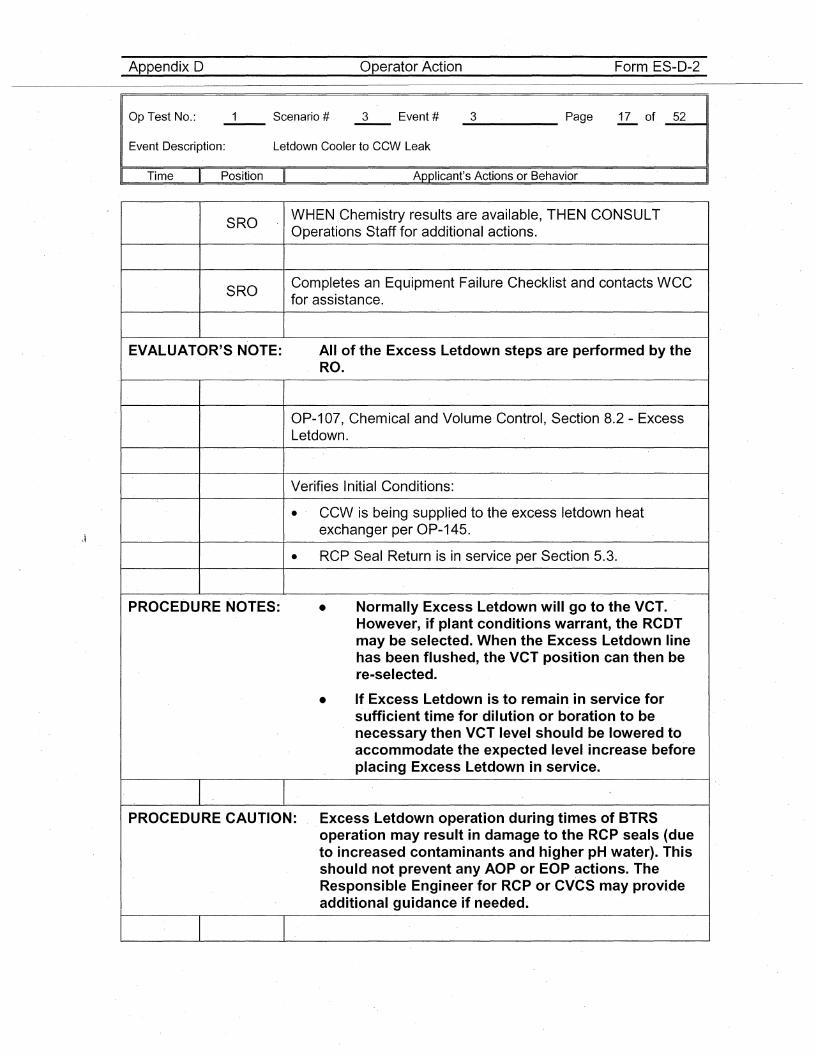
Appendix D Operator Action Form ES-D-2
Op Test No.:
Event Description: Letdown Cooler to CCW Leak
_3 Page 17 of _5_2__11
Time Position
SRO
SRO
Applicant's Actions or Behavior
WHEN Chemistry results are available, THEN CONSULTOperations Staff for additional actions.
Completes an Equipment Failure Checklist and contacts WCCfor assistance.
•
EVALUATOR'S NOTE:
PROCEDURE NOTES:
All of the Excess Letdown steps are performed by theRO.
OP-107, Chemical and Volume Control, Section 8.2 - ExcessLetdown.
Verifies Initial Conditions:
• CCW is being supplied to the excess letdown heatexchanger per OP-145.
• RCP Seal Return is in service per Section 5.3.
Normally Excess Letdown will go to the VCT.However, if plant conditions warrant, the RCDTmay be selected. When the Excess Letdown linehas been flushed, the VCT position can then bere-selected.
• If Excess Letdown is to remain in service forsufficient time for dilution or boration to benecessary then VCT level should be lowered toaccommodate the expected level increase beforeplacing Excess Letdown in service.
PROCEDURE CAUTION: Excess Letdown operation during times of BTRSoperation may result in damage to the RCP seals (dueto increased contaminants and higher pH water). Thisshould not prevent any AOP or EOP actions. TheResponsible Engineer for RCP or CVCS may provideadditional guida-nee if needed.
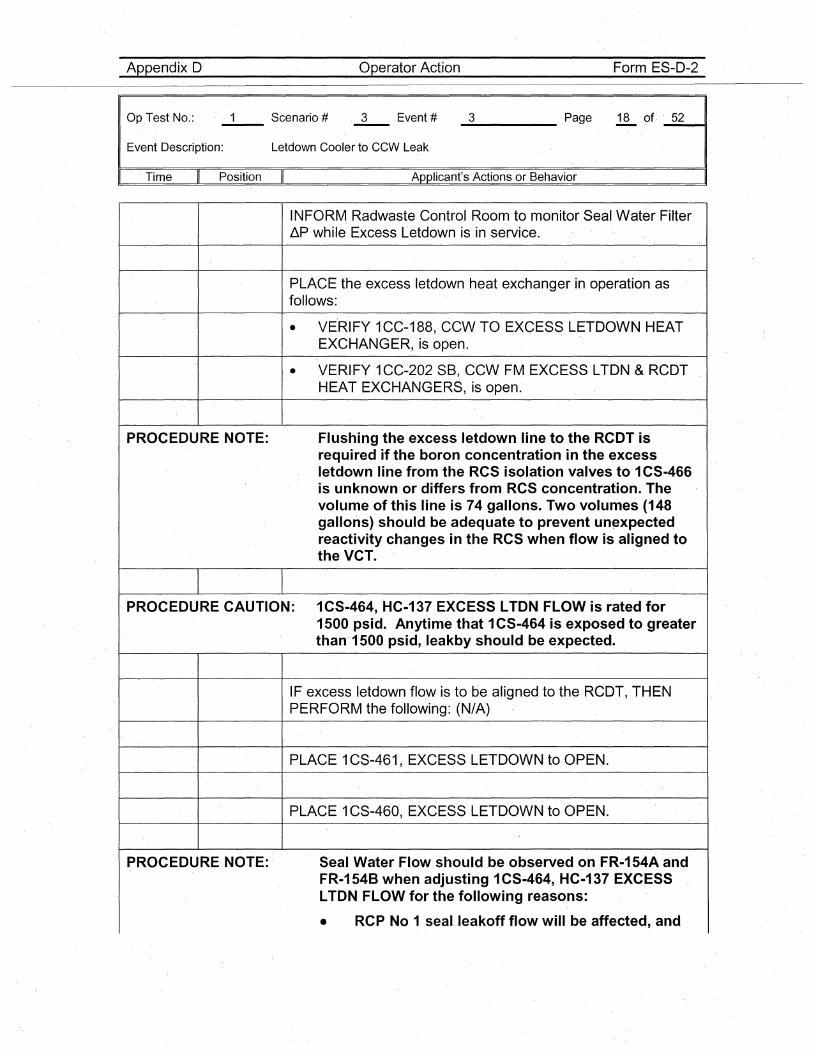
Appendix D Operator Action Form ES-D-2
Op.Test No.:
Event Description: Letdown Cooler to CCW Leak
_3 Page 18 of. _5_2---41
. Time Position Applicant's Actions or Behavior
INFORM Radwaste Control Room to monitor Seal Water FilterliP while Excess Letdown is in service·.
PLACE the excess letdown heat exchanger in operation asfollows:
• VE·RIFY 1CC-188, CCW.TO EXCESS LETDOWN HEAT.EXCHANGER, is open.
• VERI FY .1CC~202 SB, CCW FM EXCESS LTDN & RCDTHEAT EXCHANGERS, is open.
PROCEDURE NOTE: Flushing the excess letdown line to the RCDT isrequired if the boron concentration in the excessletdown line from the RCS isolation valves to 1CS-466is unknown or differs from RCS concentration. Thevolume of this line is 74 gallons. Two volumes (148gallons) should be adequate to prevent un~xpectedreactivity changes in the RCS when flow is align'ed tothe VCT.
PROCEDURE CAUTION: 1CS-464, HC-137·EXCESS LTDN FLOW is rated for1500 psid. Anytime that 1CS-464 is exposed to greaterthan· 1500 psid, leakby should be expected.
IF excess letdown flo.w is to·be aligned to the RCDT, THENPERFORM the following: (N/A)
PLACE 1CS-461, EXCESS LETDOWN to OPEN.
PLACE 1CS-460, EXCESS LETDOWN to OPEN.
PROCEDURE NOTE: Seal Water Flow should be observed on FR-154A andFR-1548 when adjusting 1CS-464, HC-137 EXCESSLTON FLOW for the following reasons:
• RCP No 1 sealleakoffflow will be affected, and
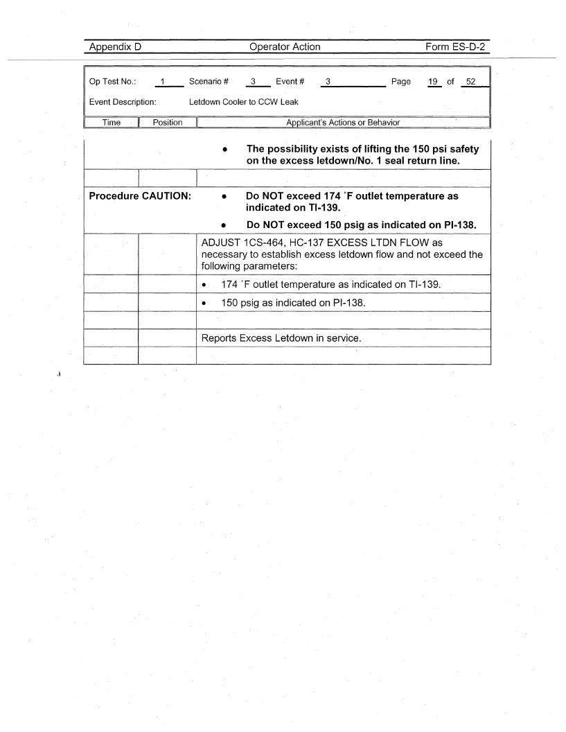
Appendix 0 Operator Action Form ES-D-2
Op Test No.:
Event Description: Letdown Cooler to CCW Leak
_3 Page 19 of _5_2---11
Time Position Applicant's Actions or Behavior
• The possibility exists of lifting the 150 psi safetyon the excess letdown/No.1 seal return line.
Procedure CAUTION: • Do NOT exceed 174 of outlet temperature asindicated on TI-139.
• Do NOT exceed 150 psig as indicated on PI-138.
ADJUST 1CS-464, HC-t37 EXCESS LTON FLOW asnecessary to establish excess letdown flow and not exceed thefollowing parameters:
• 174 of outlet temperature as indicated on TI-139.
• 150 psig as indicated on PI-1.38.
Reports Excess Letdown in service.
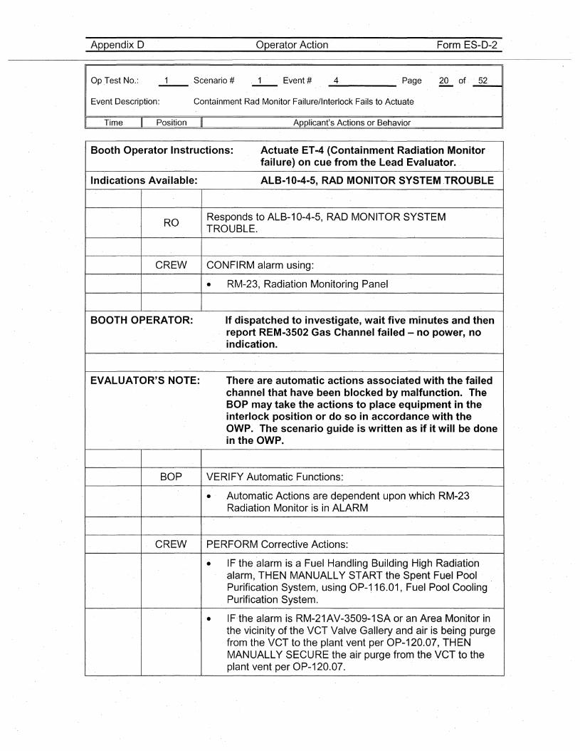
Appendix D Operator Action Form ES-D-2
Op .Test No.:
Event Description:
_4 · Page 20 of· _5_2---11
ContainmentRad Monitor Failure/Interlock Fails to Actuate
. Time Position Applicant's Actions or Behavior
Booth Operator Instructions: Actuate ET-4 (Containment Radiation Monitorfailure) on cue from the Lead Evaluator..
Indications Available: ALB-10-4-5, RAD MONITOR SYSTEM .TROUBLE
ROResponds to ALB-1 0-4-5, RAD MONITOR SYSTEMTROUBLE.
CREW CONFIRM alarm using:
• RM-23, Radiation Monitoring Panel
BOOTH OPERATOR: If dispatched to investigate, wait five minutes and thenreport REM-3502 Gas Channel failed - no power, noindication.
EVALUATOR'S NOTE: There are automatic actions associated with the failedchannel that have been blocked by malfunction. TheBO·P may take the actions to place equipment in theinterlock position or do so in accordance with theOWP. The scenario guide is written as if it will be donein the OWP.
BOP VERIFY Automatic· Functions:
• Automatic Actions are dependent upon which RM-23Radiation Monitor is in ALARM
CREW PERFORM Corrective Actions:
• IF the alarm is a Fuel Handling Building High Radiationalarm~ THEN MANUALLY START the Spent Fuel PoolPurification System, using OP-·116.01, Fuel Pool CoolingPurification System.
• IF·the alarm is RM-21AV-3509-1SA or an Area Monitor inthe vicinity· of the VCT Valve Gallery and air is being pur.gefrom the VCT to the plant vent per OP-120.07,THENMANUALLY SECURE·the air purge from the VCT to theplant vent per OP~120.07.
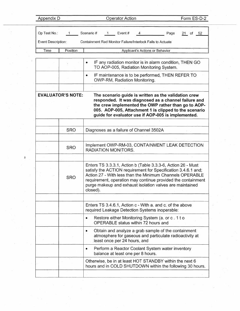
AppendixD Operator Action Form ES-D-2
Op Test No.:
Event Description:
_4 Page 21 of _5_2---11
Containment Rad Monitor Failure/Interlock Fails to Actuate
Time Position Applicant's Actions or Behavior
\~
• IF any radiation monitor is in alarm condition, THEN GOTO AOP-005, Radiation Monitori.ng System.
• IF maintenance is to be performed, THEN REFER TOOWP-RM, Radiation Monitoring.
EVALUATOR'S NOTE: The scenario guide is written as the validation crewresponded. It was diagnosed as a channel failure andthe crew implemented the OWP rather than go to AOP-005. AOP-005, Attachment 1 is clipped to the scenarioguide for evaluator use if AOP-005 is implemented.
SRO Diagnoses as a failure of Channel 3502A
SROImplement OWP-RM-03, CONTAINMENT LEAK DETECTIONRADIATION MONITORS.
Enters TS 3.3.3.1, Action b (Table 3.3.3-6, Action 26 - Mustsatisfy the ACTION requirement for Specification 3.4.6.1 and;
SROAction 27 - With·lessthan the Minimum Channels OPERABLErequirement, operation may continue provided the containmentpurge makeup and exhaust isolation valves are maintainedclosed).
Enters TS 3.4.6.1, Action c - With a. and c~ of the aboverequired Leakage Detection Systems inoperable:
• Restore either Monitoring System (a. or c . 1 t 0
OPERABLE status within 72 hours and
• Obtain and analyze a grab sample of the containmentatmosphere for gaseous and particulate radioactivity atleast once per 24 hours, and
• Perform a Reactor Coolant System water inventorybalance at least one per 8 hours.
Otherwise, be in at least HOT STANDBY within the. next 6.hours and in COLD SHUTDOWN within the following 30 hours.
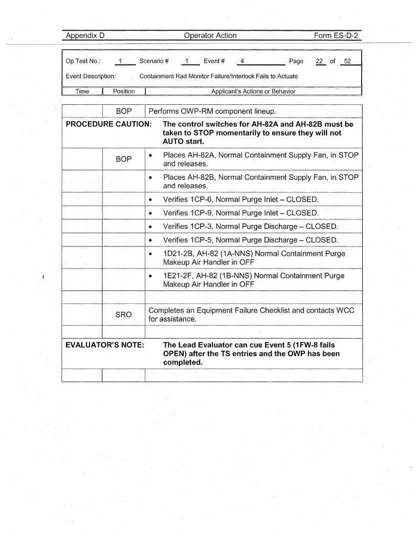
Appendix D Operator Action Form ES-D-2
Op Test No.:
Event Description:
_4 Page 22 of _5_2----11
Containment Rad Monitor Failure/Interlock Fails to Actuate
Time Position Applicant's Actions or Behavior
BOP Performs OWP-RM component lineup.
PROCEDURE CAUTION: The control switches for AH-82A and AH-828 must betaken to STOP momentarily to ensure they will notAUTO start.
BOP • Places AH-82A" Normal Containment Supply Fan, in STOPand releases.
• Places AH-82B, Normal Containment Supply Fan, in STOPand releases.
• Verifies 1CP-6, Normal Purge Inlet '- CLOSED.
• Verifies 1CP-9, Normal Purge Inlet - CLOSED.
• Verifies 1C.P-3, Normal Purge Discharge - CLOSED.
• Verifies 1CP-5, Normal Purge Discharge - CLOSED.
• 1D21-2B, AH-82 (1A-NNS) Normal Containment PurgeMakeup Air Hanqler in OFF
• 1E21-2F, AH-82 (1 B'-NNS) Normal Containment PurgeMakeup Air Handler in OFF
S,RO Completes an Equipment Failure Checklist and contacts WCCfor assistance.
EVALUATOR'S NOTE: The Lead Evaluator can ,cue Event 5 (1 FW-8 failsOPEN) after·the TS entries and the OWP has beencompl.eted.
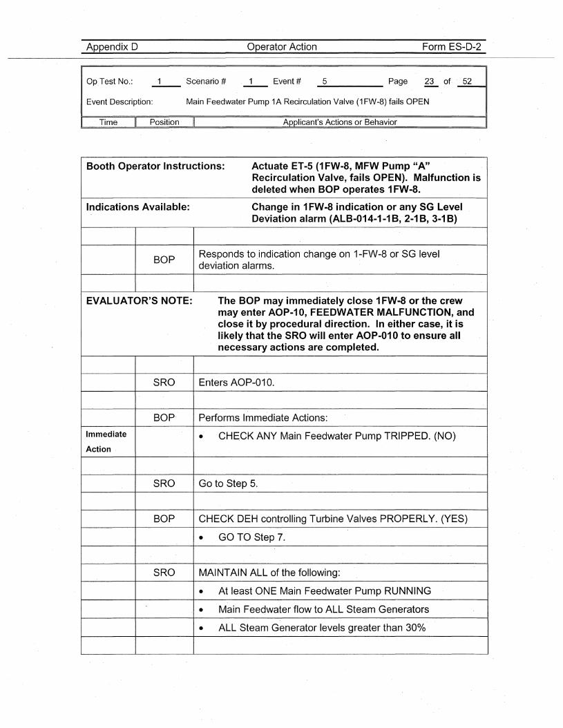
Appendix D Operator Action Form ES-D-2
Op.Test No.:
Event Description:
_5 Page 23 of. _5_2----11
Main Feedwater Pump 1A Recirculation Valve (1 FW-8) fails OPEN
Time II Position II Applicant's Actions or Behavior
Booth Operator Instructions: Actuate ET-5 (1 FW-8, MFW Pump "A"Recirculation Valve, fails OPEN). Malfunction isdeleted when BOP operates 1FW-8.
Indications Available: Change in 1FW-8 indication or any SG LevelDeviation alarm (ALB-014-1-1 B, 2-1 B, 3-1 B)
BOPResponds to .indication change on 1-FW-8 or SG leveldeviation alarms.
EVALUATOR'S NOTE: The BOP may immediately close 1FW-8 or the crewmay e·nter AOP-10, FEEDWATER MALFUNCTION, andclose it by procedural direction. In either case, it islikely that the SRO will enter AOP-01 0 to ensure allnecessary actions are completed.
SRO Enters AOP-01 O.
BOP Performs Immediate Actions:
Immediate • CHECK ANY Main Feedwater Pump TRIPPED. (NO)Action
SRO Go to Step 5.
BOP CHECK DEH controlling Turbine Valves PROPERLY. (YES)
• GO TO Step 7.
SRO MAINTAIN ALL of the following:
• At least ONE Main Feedwater Pump RUNNING
• Main Feedwater flow to ALL Steam Generators
• ALL Steam Generator levels greater than 30%
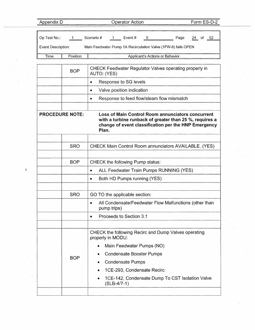
Appendix D Operator Action Form ES-D~2
Op Test No.:
Event Description:
_5 Page 24 of _5_2---11
Main Feedwater Pump 1A Recirculation Valve (1 FW·-8) fails OPEN
Time Position Applicant's Actions or Behavior
BOPCHECK Feedwater Regulator Valves operating properly inAUTO: (YES)
• Response to SG levels
• Valve position indication
• Response to feed flow/steam flow mismatch
P'ROCEDURE NOTE: Loss of Main Control Room annunciators concurrentwith a turbine runback of greater than 25 0/0, requires achange of event classification per the HNP EmergencyPlan.
SRO CHECK Main Control Room annunciators AVAILABLE. (YES)
BOP CHECK the following Pump status:
• ALL Feedwater Train Pumps RUNNING (YES)
• Both HD Pumps running (YES)'
SRO GO TO the applicable section:
• All Condensate/Feedwater Flow Malfunctions (other thanpump trips)
• Proceeds to Section 3.1
CHECK the following Recirc and Dump Valves operating'properly in MODU:
• Main .Feedwater Pumps (NO)
• Condensate Booster PumpsBOP
• Condensate Pumps
• 1CE-293, Condensate Recirc
• 1CE-142, Condensate Dump To CST Isolation Valve(SLB~4/7-1 )
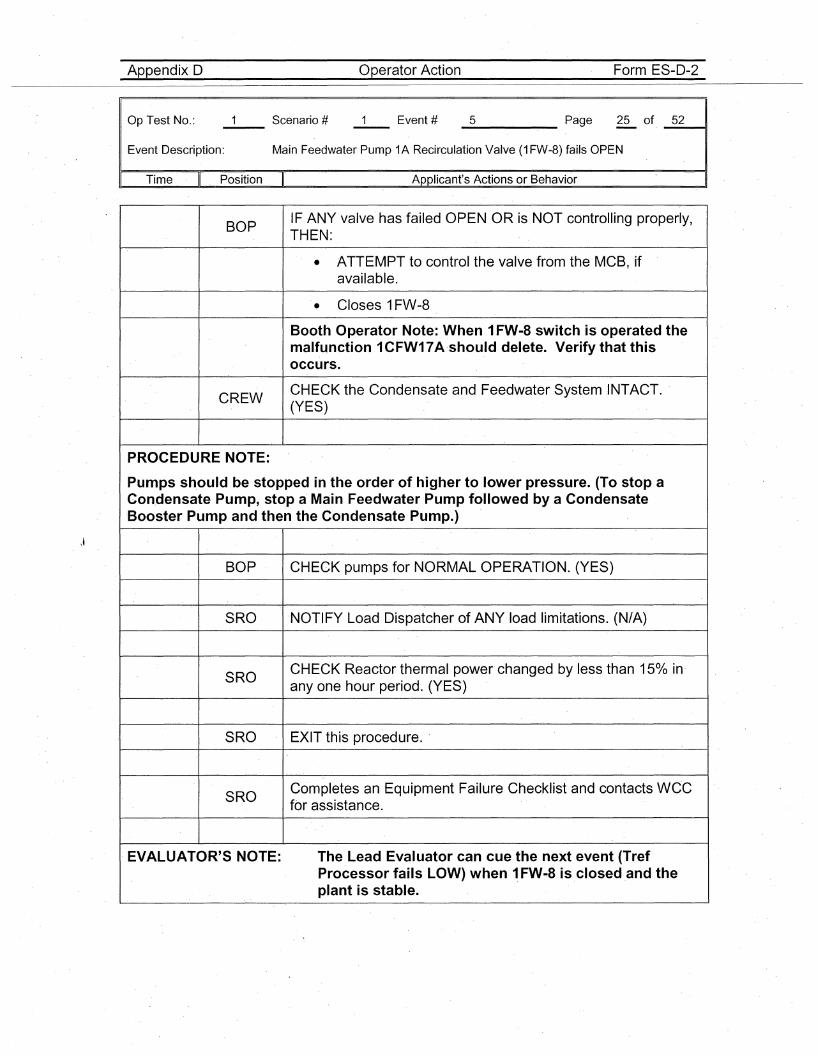
Appendix D Operator Action Form ES-D-2
Op Test No.:
Event Description:
_5 Page 25 of _5_2---11
Main Feedwater Pump 1A Recirculation Valve (1 FW-8) fails OPEN
Time Position Applicant's Actions or Behavior
BOPIF ANY valve hasfailed OPEN OR is NOT controlling properly,THEN:
• ATTEMPT to control the valve from the MCB, ifavailable.
• Closes 1FW-8
Booth Operator Note: When 1FW-8 switch is operated themalfunction 1CFW17A ·should delete. Verify that thisoccurs.
CREWCHECK the Condensate and Feedwater System INTACT.(YES)
PROCEDURE NOTE:
Pumps sh.ould be stopped in the order of higher to lower pressure. (To stop aCon.densate Pump, stop a· Main Feedwater Pump followed by a CondensateBooster Pump and then the Condensate Pump.)
BOP CHECK pumps for NORMAL OPERATION. (YES)
SRO NOTIFY Load Dispatcher of ANY load limitations. (N/A)
SROCHECK Reactor thermal powerchanged by less than 150/0 in·anyone hour period. (YES)
SRO EXIT this procedure..
SROCompletes an Equipment Failure Checklist and contacts WCCfor assistance.
EVALUATOR'S NOTE: The Lead Evaluator can cue the next event (TrefProcessor fails LOW) when ~ FW-8 is closed and theplant is stable.
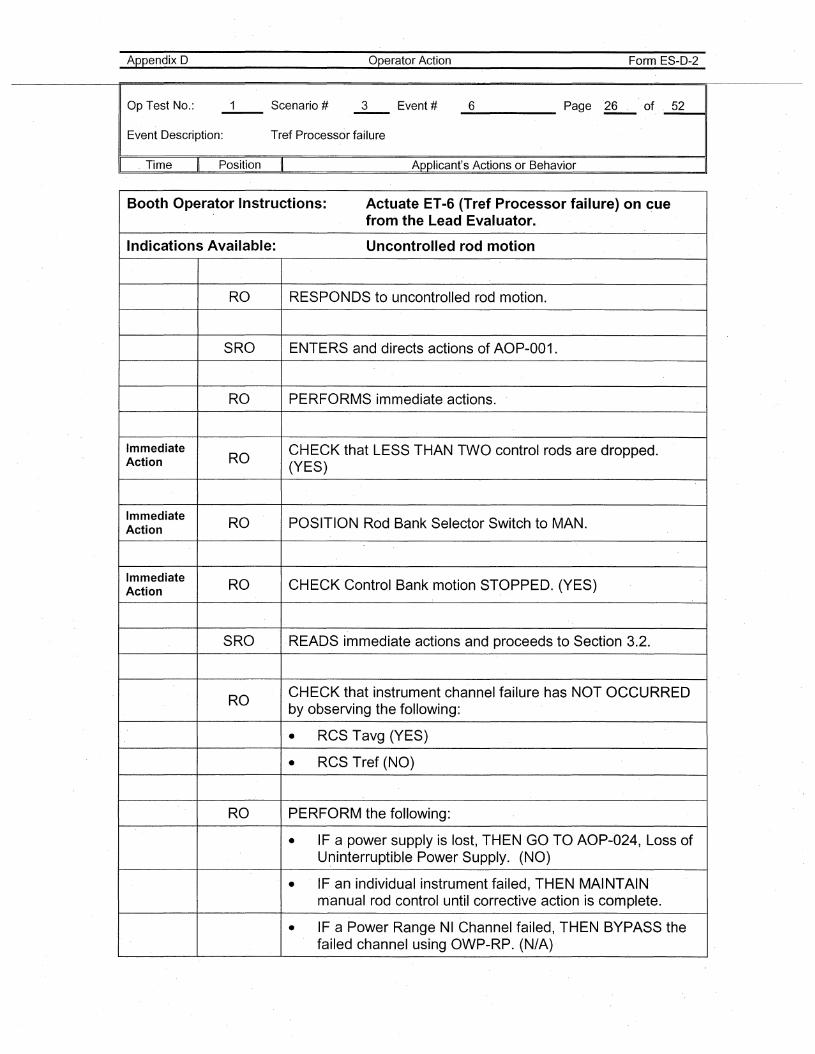
Appendix D
Op Test No.:
Event Description:
Operator Action
Tref Processor failure
Form ES-D-2
_6 Page "26 of _5_211
" Time Position Applicant's Actions or Behavior
Booth Operator Instructions: Actuate ET-6 (Tref Processor failure) on cuefrom the Lead Evaluator.
Indications Available: Uncontrolled rod motion
RO RESPONDS to uncontrolled rod motion.
SRO ENTERS and directs actions of AOP-001.
RO PERFORMS" immediate actions.
Immediate CHECK that LESS THAN TWO control rods are dropped.Action RO
(YES)
ImmediateRO POSITION Rod Bank Selector Switch to MAN.Action
Immediate RO CHECK Control Bank motion STOPPED. (YES)Action
SRO READS immediate actions and proceeds to Section 3.2.
ROCHECK that instrument channel failure has NOT OCCURREDby observing the following:
• RCS Tavg (YES)
• RCS Tref (NO)
RO PERFORM the following:
• IF a power supply is lost, THEN GO TO AOP-024, Loss ofU~interruptibl"ePower Supply. (NO)
• IF an individual instrument failed, THEN MAINTAINm"anual rod control until corrective action is complete.
• IF a Power Range NI Channel failed, THEN BYPASS thefailed channel using OWP-RP. (N/A)
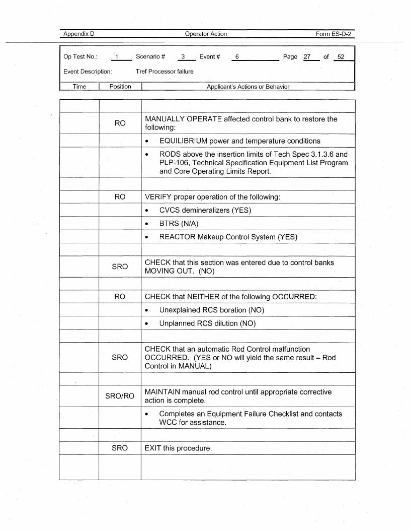
6
Appendix 0
Op Test No.:
Event Desc~iption:
Operator Action
Tref Processor failure
Form ES-D-2
Page .27 of 52----- -----II
. Time II Position II Applicant's Actions or Behavior
ROMANUALLY OPERATE affected control bank to restore thefollowing:
• EQUILIB.RIUM power and temperature conditions
• RODS above the insertion limits of Tech Spec 3.1.3.6 andPLP-106, Te'chnical Specification Equipment List Programand Core Operating Limits Report.
RO VERIFY proper operation of the following:
• CVC.S demineralizers (YES)
• BTRS (N/A)
• REACTOR Makeup Control System (YES)
SROCHECK that this section was entered du,e to control banksMOVING OUT. (NO)
RO CHECK that NEITHER of the following OCCURRED:
• Unexplained RCS boration (NO)
• Unplanned RCS dilution (NO)
CHECK that an automatic Rod Control malfunctionSRO OCCURRED. (YES or NO will yield the same result - Rod
Control in MANUAL)
SRO/ROMAINTAIN manual rod control until appropriate correctiveaction is complete.
• Completes an Equipment Failure Checklist and contacts·WCC for assistance.
SRO EXIT this procedure.
Appendix 0
Op Test No.: Scenario #--- 3
Operator Action
Event # 6 Page 28
Form ES-D-2
of 52
Event Description: Tref Processor failure
Time Position Applicant's Actions or Behavior
EVALUATOR'S NOTE: When Tavg is restored and AOP-001 exited, cueinitiation of Event 7 (Secondary Load Rejection).
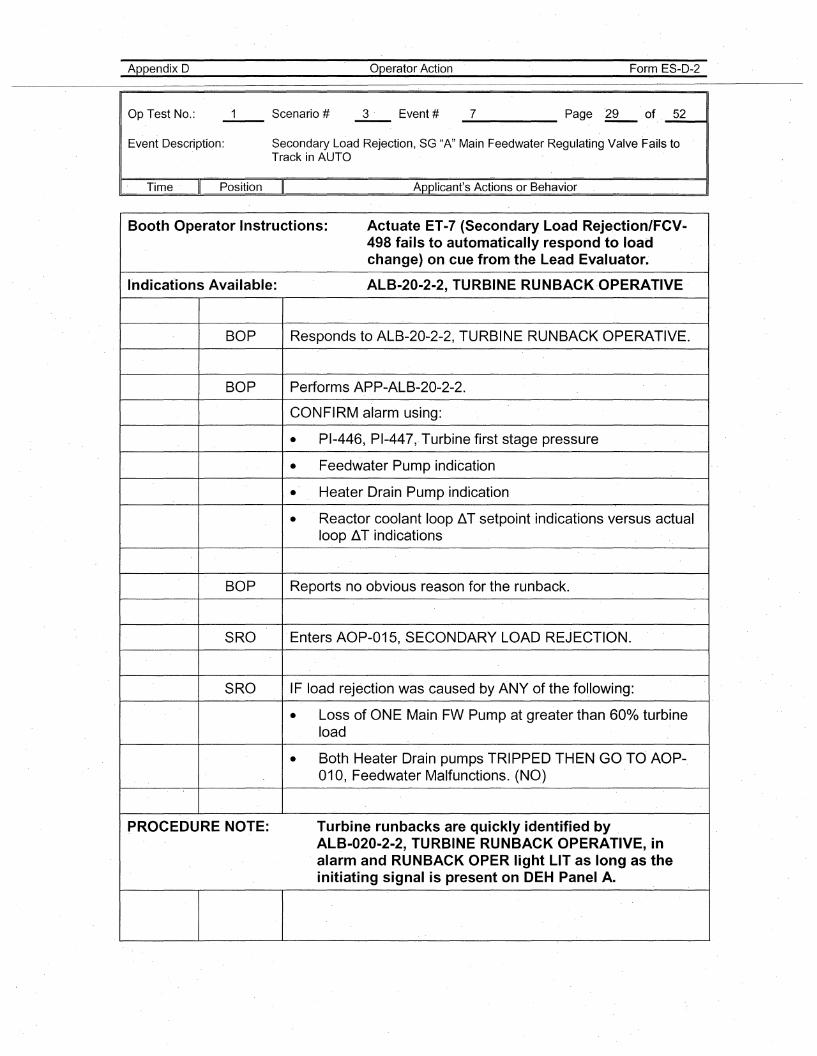
Appendix 0
Op Test No.:
Operator Action Form ES-D-2
_7 Page ~ of. _5_2---41
Event Description: Secondary Load Rejection, SG "A" Main Feedwater Regulating Valve Fails toTrack in AUTO
I· Time Position Applicant's Actions or Behavior
Booth Operator Instructions: Actuate ET-7 (Secondary Load Rejection/FCV-498 fails to automatically respond to.loadchange) on cue from the Lead Evaluator.
Indications Available: ALB-20-2-2, TURBINE RUNBACK·OPERATIVE
BOP Responds to ALB-20-2-2, TURBINE RUNBACK OPERATIVE.
BOP Performs APP-ALB-20-2-2.
CONFIRM alarm using:
• PI-446, PI-447,.Turbine first stage pressure
• Feedwater Pump indication
• Heater Drain Pump indication
• Reactor coolant loop liT setpoint indications versus actualloop liT indications
BOP Reports no obvious reason for the runback.
SRO Enters AOP-015, SECONDARY LOAD REJECTION.
SRO IF load rejection was caused ·by ANY of the foUowing:
• Loss of ONE Main FW Pump at greater than 600/0 turbineload
• Both Heater Drain pumps TRIPPED THEN GO TO AOP-010, Feedwater Malfunctions. (NO)
PROCEDURE NOTE: Turbine runbacks are quickly identified byALB-020-2-2, TURBINE RUNBACK OPERATIVE, inalarm and RUNBACK OPER light LIT as long as theinitiating signal is present on DEH Panel A.
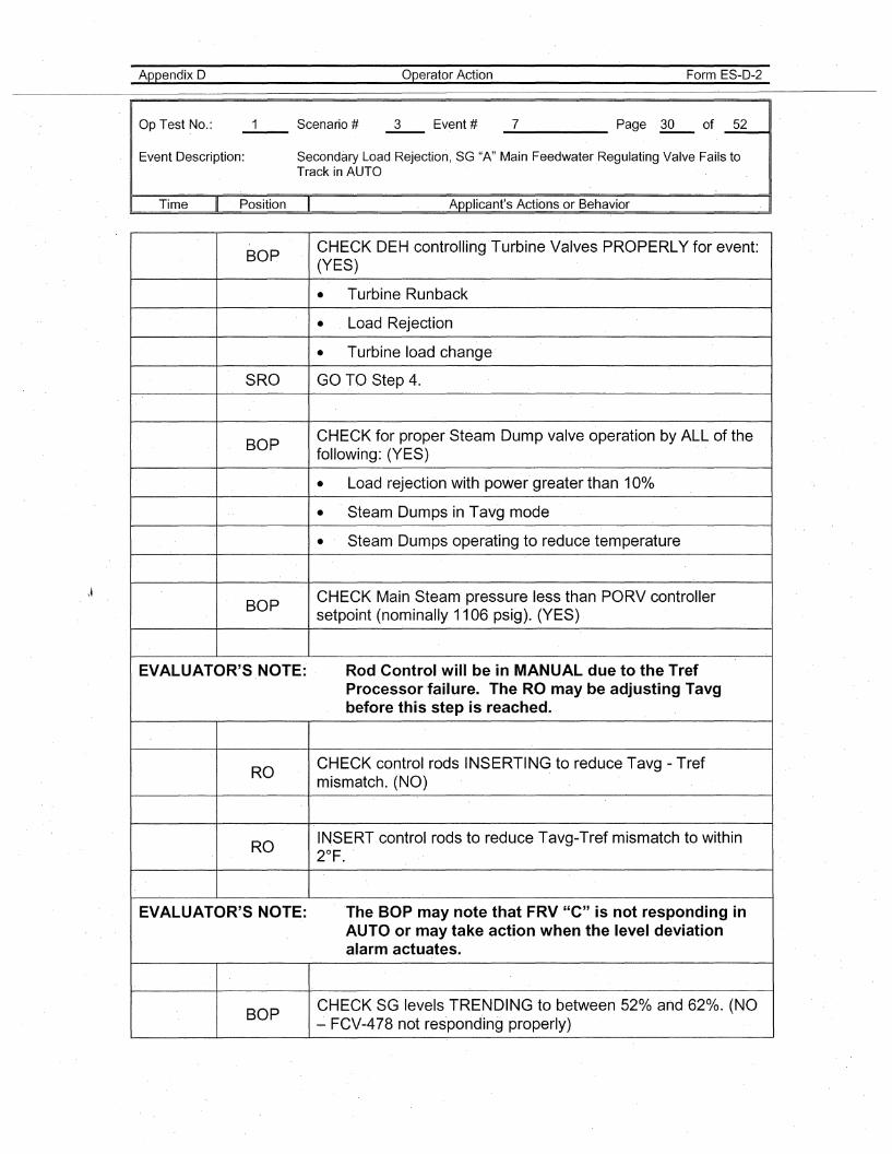
Appendix D
Op Test No.:
Operator Action Form ES-D-2
_7 Page~ of _5_2__11
Event Description: Secondary Load Rejection, SG "A" Main FeedwaterRegulating Valve Fails toTrack in AUTO
Time Position Applicant's Actions or Behavior . I
BOPCHECK DEH controlling Turbine Valves PROPERLY for event:(YES)
• Turbine Runback
• Load Rejection
• Turbine load change
SRO GO TO Step 4.
BOPCHECK for proper Steam Dump valve operation by ALL of thefollowing: (YES)
• Load rejection with power greater than 10%
• Steam Dumps in Tavg mode
• Steam Dumps operating to reduce temperature
BOPCHECK Main Steam' pressure less than PORV controllersetpoint (nominally 1106 psig). (YES)
EVALUATOR'S NOTE: Rod Control wiU be in MANUAL due to the TrefProcessor failure. The RO may be adjusting Tavgbefore this step is reached.
ROCHECK control rods INSERTING to reduce Tavg - Trefmismatch. (NO)
ROIN.SERT control rods to reduce Tavg-Tref mismatch to within2°F.
EVALUATOR'S NOTE: 'The BOP may note that FRV "C" is not responding inAUTO or may take action when the level deviationalarm actuates.
BOPCHECK SG levels TRENDING to between 52% and 62%. (NO~ FCV-478 not responding properly)
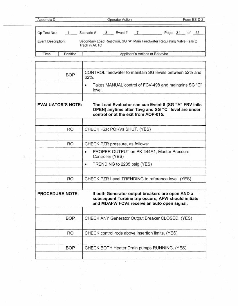
Appendix D
Op Test No.:
Operator Action Form ES-D-2
_7 Page l.:!- of _5_2---11
Event Description: Secondary Load Rejection, SG "A" Main Feedwater .Regulating Valve Fails toTrack in AUTO
Time Position Applicant's Actions or Behavior . I
BOPCONTROL feedwater to maintain SG levels between 520/0 and620/0.
• Takes MANUAL control of FCV-498 and maintains SG "C"level.
EVALUATOR'S NOTE: The Lead Evaluator can cue Event 8 (SG "A" FRV failsOPEN) anytime after Tavg and SG "C" level are undercontrol or at the exit from AOP-O.15.
RO CHECK PZR PORVs SHUT. (YES)
RO CHECK PZR pressure, as follows:
• PROPER OUTPUT on PK-444A1, Master PressureController (YES)
• TRENDING to 2235 psig (YES)
RO CHECK PZR Level TRENDING to reference level. (YES)
PROCEDURE NOTE: If both Generator output breakers are open AND asubsequent .Turbine trip ·occurs, AFW should initiateand MDAFW FCVs receive an auto open signal.
BOP ·CHECK ANY Generator Output Breaker CLOSED. (YES)
RO CHECK control rods above insertion limits. (YES)
BOP CHECK BOTH Heater Drain pumps RUNNING. (YES)
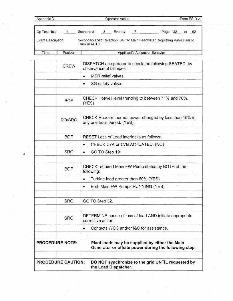
Appendix D
Op Test No.:
Operator Action Form ES-D-2
_7 ·Page -R-. of _5_2----11
Event Description: Secondary Load Rejection, SG "A" Main Feedwater .Regulating Valve Fails toTrack in AUTO
Time Position Applicant's Actions or Behavior . I
CREWDISPATCH an operator to check the following SEATED, byobservance of tailpipes:
• MSR relief valves
• SG safety va.lves
BOPCHECK Hotwell level trending to between 710/0 and 76%.(YES)
RO/SROCHECK Reactor thermal power changed by less than 150/0 inanyone hour period. (YES)
BOP RESET Loss of Load interlocks as follows:
• CHECK C7Aor C7B ACTUATED. (NO)
SRO • GO TO Step 19
BOPCHECK required -MainFW Pump status by BOTH of thefollowing:
• Turbine load, greater than 600/0 (YES)
• Both Main FW Pumps RUNNING (YES)
SRQ GO TO Step 32.
SRO'DETERMINE cause of loss of load AND initiate appropriatecorrective action..' Contacts WCC and/or I&C for assistance.
PROCEDURE NOTE: Plant loads may be supplied by either the MainGenerator or offsite power during the following step.
PROCEDURE CAUTION: DO NOT synchronize to the grid UNTIL requested bythe Load Dispatcher.
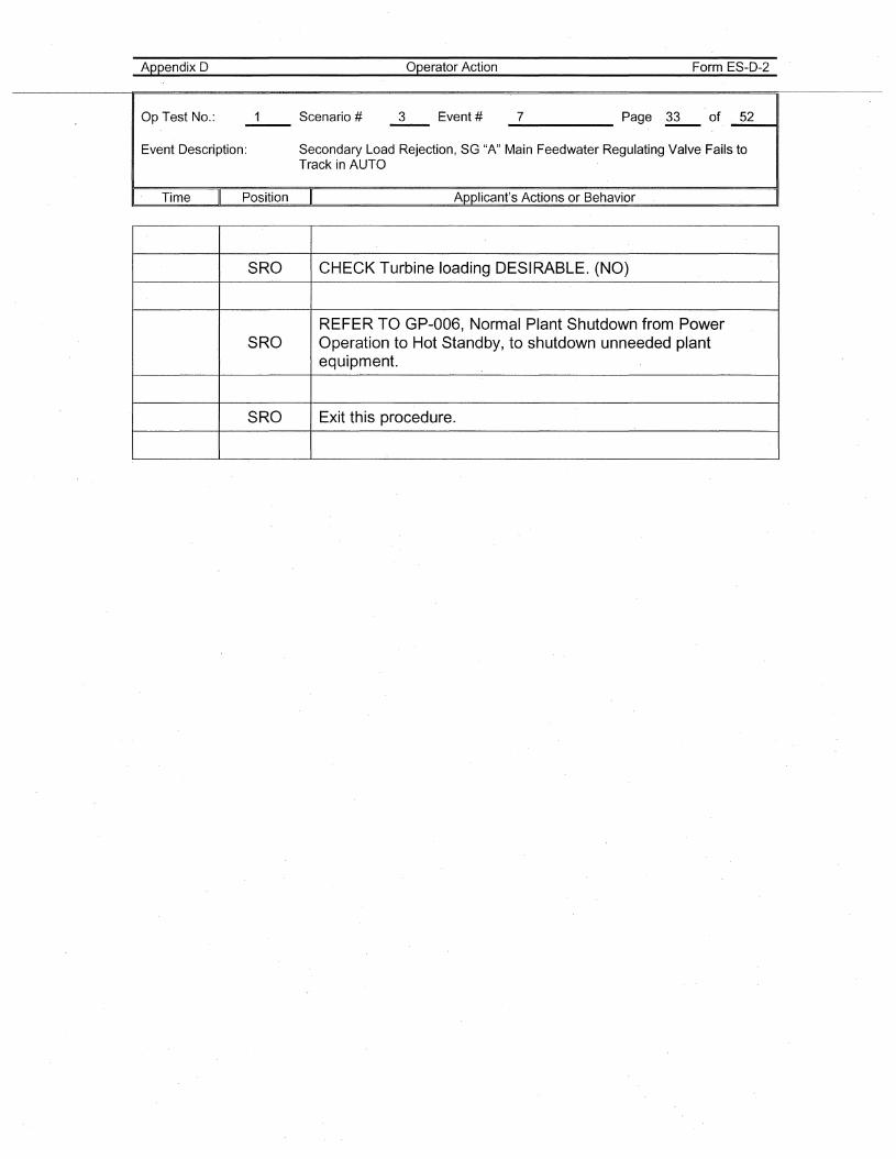
Appendix D
Op Test No.: Scenario #-- 3
Operator Action
Event #
Form ES-D-2
_7 Page ~ of _5_2__11
Event Description: Secondary Load Rejection, SG "A" Main Feedwater Regulating Valve Fails toTrack in AUTO
I· Time Position Applicant's Actions or Behavior
SRO CHECK Turbine loading DESIRABLE. (NO)
REFER TO GP-006, Normal Plant Shutdown from PowerSRO Operation to Hot Standby, to shutdown unneeded plant
equipment.
SRO Exit this procedure.
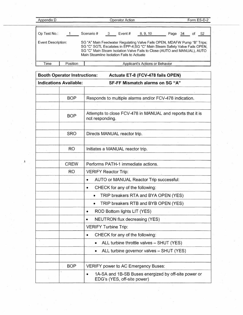
Appendix D
Op Test No.: 3
Operator Action
Event #
Form ES-D-2
_8..-,_9-..,1_0 Page ~ of _5_2----11
Event Description: SG "A" Main Feedwater Regulating Valve Fails OPEN, MDAFW Pump "B" Trips;SG "C" SGTL Escalates in EPP-4;SG "C" Main Steam Safety Valve Fails OPEN,SG "C" Main Steam Isolation Valve Fails to Close (AUTO and MANUAL)" AUTOMain Steamline Isolation Fails to Actuate
. I Time Position Applicant's Actions or Behavior
Booth Operator Instructions: Actuate ET.-8 (FCV-478 fails OPEN)
Indications Available: SF-FF Mismatch alarms on SG "A"
BOP Responds to multiple alarms and/or FCV-478 indication.
BOP· Attempts to close FCV-478 in MANUAL and reports that 'it isnot responding.
SRO Directs MANUAL reactor trip.
RO Initiates a MANUAL reactor trip.
CREW Performs PATH-1 imm'ediate actions.
RO VERIFY Reactor Trip:
• AUTO or MANUAL ReactorTrip successful:
• CHECK for any of the following:
• TRIP breakers RTA and BYA OPEN (YES)'
• TRIP breakers RTB and BYB OPEN (YES)
• ROD Bottom lights LIT (YES)
• NEUTRON flux decreasing (YES)
.VERI FY Turbine Trip:
• CHECK.for any of the following:
• . ALL turbine throttle valves - SHUT (YES)
• ALL turbine governor valves - SHUT (YES)
BOP VERIFY power to AC Emergency Buses:
• 1A-SA and·1 B-SB Buses energized by off-site power orEDG's (YES, off-site power)
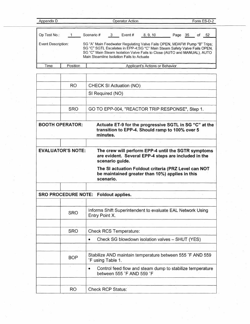
Appendix 0
Op Test No.:
Operator Action Form ES-D-2
_8......,_9-..,1_0 Page .~ of. _5_211
Event Description: SG "A"· Main Feedwater Regulating Valve Fails OPEN, MDAFW Pump "B" Trips;SG "C" SGTL Escalates in EPP-4;SG "C" Main Steam Safety.Valve Fails OPEN,SG "C" Main Steam Isolation Valve Fails to Close (AUTO and MANUAL), AUTOMain Steamline Isolation Fails to Actuate
Time Position Applicant's Actions or Behavior
RO CHECK SI Actuation (NO) .
SI Required (NO)
SRO GO TO EPP-004, "REACTOR TRIP RESPONSE", Step 1.
BOOTH OPERATOR: Actuate .ET-9 for the progressive SGTL in SG "C" at the.transition to EPP-4. Should ramp to 1000/0 over 5minutes.
EVALUATOR'S NOTE: The crew will perform EPP-4 until the SGTR symptoms·are evident. Several EPP-4 steps are included in thescenario· guide.
The SI actuation Foldout criteria (PRZ Level can NOTbe·maintained greater than 10%) applies in·thisscenario.
SRO PROCEDURE NOTE: Fold.out applies.
SROInforms Shift Superintendent to evaluate EAL Network UsingEntry Point X.
SRO Check RCS·Temperature:
• Check SG blowdown isolation valves - SHUT (YES)
BOPSta·bilize AND maintain temperature between 555 of AND 559of using Table 1.
• Control feed flow and steam .dump to stabilize temperaturebetween 555 °F AN D 559 °F
RO Check RCP Status:
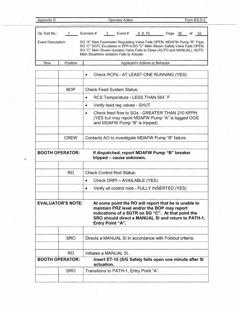
Appendix D
Op Test No.:
Operator Action Form ES-D-2
_8..-,_9,-..1_0___ Page ~ of _5_241
Event Description: SG "A" Main Feedwater Regulating Valve Fails OPE.N, MDAFW Pump "B" Trips;SG "G" SGTL Escalates in EPP-4;SG "G" Main Steam Safety Valve Fails OPEN,SG "G" Main Steam Isolation Valve Fails toGlose (AUTO and MANUAL)"AUTOMain Steamline Isolation Fails to Actuate
. I Time Position Applicant's Actions or Behavior
• Check Reps - AT LEAST ONE RUNNING (YES)
BOP Check Feed System Status:
• RCS Temperature - LESS THAN 564 of
• Verify feed reg valves - SHUT
• Check feed flow to SGs - GREATER THAN 210 KPPH·(YES but may report MDAFW Pump "A" is tagged OOSand MDAFW Pump "B" is tripped)
CREW Contacts AO to investigate MDAFW Pump "B" failure.
BOOTH OPERATOR: If dispatched, report MDAFW Pump "B" breakertripped - cause. unknown.
RO Check Control Rod Status:
• Check DRPI -AVAILABLE (YES)
• Verify all control rods - FULLY INSERTED (YES)
EVALUATOR'S NOTE: At some point the RO will report that he is unable tomaintain PRZ level and/or the BOP may reportindi.cations of a SGTR on SG "C".At that point theSRO should direct a MANUAL SI and return to PATH-1,Entry Point "A".
SRO Directs'a MANUAL SI in accordance with Foldout criteria.
RO Initiates a MANUAL SI.
BOOTH OPERATOR: Insert ET-10 (S/G Safety fails open one minute after SIactuation.
SRO Transitions to PATH-1, Entry Point "A".
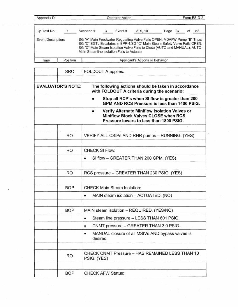
Appendix D
Op Test No.:
operator Action Form ES-D-2
_8..-.,_9....,1_0 Page R- of. _5_2---41
Event Description: SG "A" Main Feedwater Regulating Valve Fails OPEN, MDAFW Pump "B" Trips;SG "C" SGTL Escalates in EPP-4;SG "C" Main Steam Safety Valve Fails OPEN,SG "C" Main Steam Isolation Valve Fails to Close (AUTO and MANUAL), AUTOMain Steamline Isolation Fails to Actuate
'I Time Position Applicant's Actions or Behavior
SRO FOLDOUT A applies.
EVALUATOR'S NOTE: The following actions should be taken in accordancewith FOLDOUT A criteria during the scenario:
• Stop all RCP's when SI flow is greater than 200GPM AND RCS Pressure is less than 1400 PSIG.
• Verify Alternate Miniflow Isolation Valves orMiniflow Block Valves CLOSE when RCS
.Pressure lowers to less than 1800 PSIG.
RO VERIFY ALL CSIPs AND RHR pumps - RUNNING. (YES)
RO CHECK SI Flow:
• SI flow - GREATER THAN 200 GPM. (YES)
RO RCS pressure - GREATER THA·N 230 PSIG. (YES)
BOP CHECK Main Steam Isolation:
• MAIN steam isolation - ACTUATED. (NO)
BOP MAIN steam isolation - REQUIRED. (YES/NO)
• Steam line pressure - LESS THAN 601 PSIG.
• CNMT pressure - GREATER THAN 3.0 PSIG.
• MANUAL closure of all MSIVs AND bypass valves isdesired.
RO' CHECK CNMT Pressure - HAS REMAINED LESS THAN 10PSIG. (YES)
BOP CHECK AFW Status:
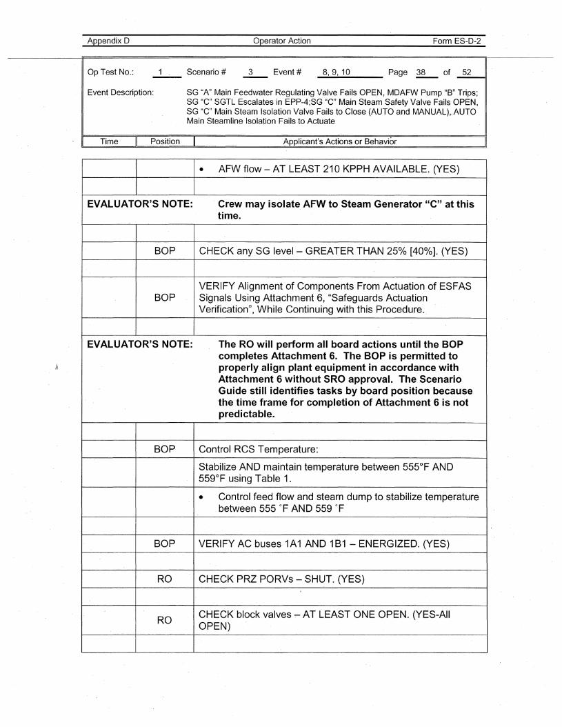
Appendix D
Op Test No.:
Operator Action Form ES-D-2
_8......,_9,-..1_0 Page ~ of _5_2---11
Event Description: SG "A" Main Feedwater Regulating Valve Fails OPEN, MDAFW Pump "B" Trips;SG "G" SGTL Escalates in EPP-4;SG "G" Main Steam Safety Valve Fails OPEN,SG "G" Main Steam Isolation Valve Fails toGlose (AUTO and MANUAL)"AUTOMain Steamline Isolation Fails to Actuate
. I Time Position Applicant's Actions or Behavior
\ ~
• AFW flow - AT LEAST 210 KPPH AVAILABLE. (YES)
EVALUATOR'S NOTE: Crew may isolate AFW to Steam Generator "e" at thistime.
BOP CHECK any SG level- GREATER THAN 250/0 [40%]. (YES)
VERIFY Alignment of Components From Actuation of ESFASBOP Signals Using Attachment 6, "Safeguards Actuation
Verification", While Continuing with this Procedure.
EVALUATOR'S NOTE: The RO will perform all board actions until the BOPcompletes Attachment 6. The BOP is permitted toproperly align plant equipment in accordance withAttachment 6 without SRO approval. The ScenarioGuide still identifies tasks by board position becausethe time frame for completion of Attachment 6 is notpredictable.
BOP Control RCS Temperature:
Stabilize AND maintain temperature between 555°F AND559°F using Table 1.
.. Control feed flow and steam dump to stabilize temperaturebetween 555 of AND 559 of
BOP VERIFY AC buses 1A1 AND 1B1 -ENERGIZED. (YES)
RO CHECK PRZ PORVs - SHUT. (YES)
ROCHECK block valves ~ AT LEAST ONE OPEN. (YES-AllOPEN)
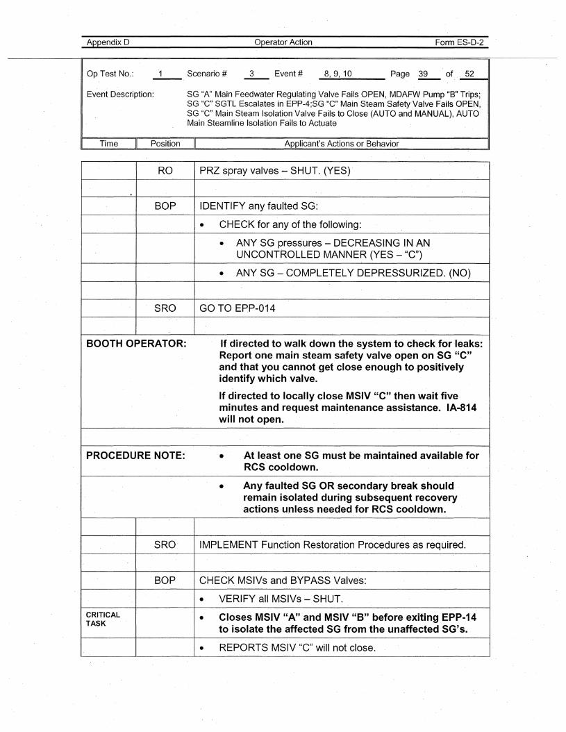
Appendix 0
Op Test No.:
Operator Action Form ES-D-2
_8....,_9..., 1_0___ Page ~ of _5_2~,
Event Description: SG "A" Main Feedwater Regulating Valve Fails OPEN, MDAFW Pump "B" Trips;SG "C" SGTL Escalates in EPP-4;SG "C" Main Steam Safety ,Valve Fails OPEN,SG "C" 'Main Steam Isolation Valve Fails to Close (AUTO and MANUAL), AUTOMain Steamline Isolation Fails to Actuate
Time II Position II Applicant's Actions or Behavior
RO PRZ spray valves - SHUT. (YES)'
'"'
BOP IDENTIFY any faulted SG:
• CHECK for any of the following:
• ANY SG pressures - DECREASING IN ANUNCONTROLLED MANNER (YES - "C")
• ANY SG - COMPLETELY DEPRES'SURIZED. (NO)
SRO GO TO EPP-014
BOOTH OPERATOR: If directed to walk down the system to check for leaks:Report one main steam safety valve open on SG "C"and that you 'cannot get close enough to positivelyidentify wh,ich valve.
If directed to locally close MSIV "C" then wait fiveminutes'and request maintenance assistance. IA-814will not open.
PROCEDURE NOTE:' • At least one SG must be maintained available forRCS cooldown.
• Any faulted SG OR secondary break shouldremain isolated during subsequent recoveryactions'unless needed for RCS cooldown.
SRO' IMPLEMENT Function Restoration Procedures as required.
BOP CHECK MSIVs and BYPASS Valve's:
• VERIFY all MSIVs - SHUT.
CRITICAL • Closes MSIV "A" and MSIV "B" before exiting EPP-14TASK
to isolate the affected SG from the unaffected SG's.
• REPORTS MSIV "C" will not close.
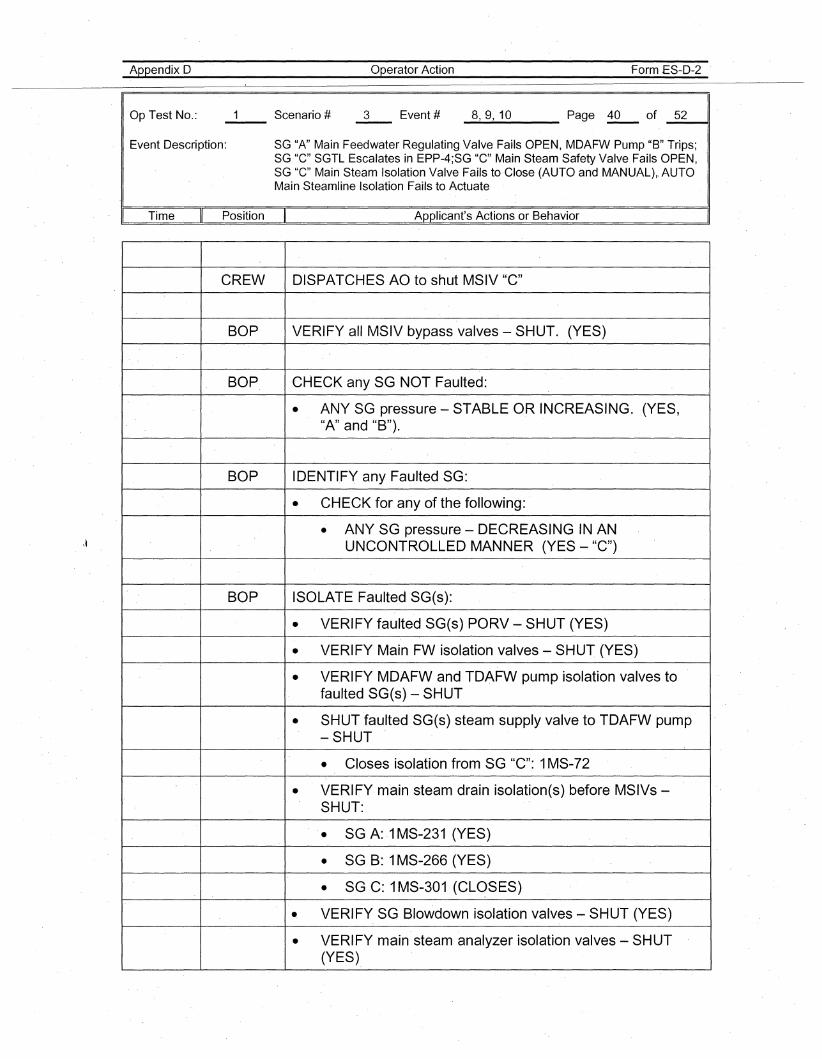
Appendix D
Op Test No.:
Operator Action Form ES-D-2
_8__,_9....,1_0 Page i2-.. of _5_2l1li11
Event Description: SG "A" Main Feedwater Regulating Valve Fails OPEN, MDAFW Pump "B" Trips;SG "C" SGTL Escalates in EPP-4;SG "C" Main Steam Safety Valve Fails OPEN,SG "C" Main Steam Isolation Valve Fails to Close (AUTO and MANUAL),. AUTOMain Steamline Isolation Fails to Actuate
. I Time Position Applicant's Actions or Behavior
CREW DISPATCHES AO to shut MSIV "c"
BOP VERIFY all MSIV bypass valves - SHUT. (YES)
BOP CHECK any SG NOT Faulted:
• ANY SG pressure - STABLE OR INCREASING. (YES,"A" and "B").
BOP IDENTI.FY any Faulted SG:
• CHECK for any of the following:
• ANY SG pressure - DECREASING IN ANUNCONTROLLED MANNER (YES - "C")
BOP ISOLATE Faulted SG(s):
• VERIFY faulted SG(s) PORV - SHUT (YES)
• VERIFY Main FW isolation valves - SHUT (YES)
• VERIFY MDAFW and TDAFW pump isolation valves tofaulted SG(s) - SHUT
• SHUT faulted SG(s) steam supply valve to TDAFW pump-SHUT
• Closes isolation from SG "C": 1MS-72
• VERIFY· main steam drain isolation(s) before MSIVs -SHUT:
• SG A:.1 MS-231 (YES)
• SG B: 1MS-266 (YES)
• SGC: 1MS-301 (CLOSES)
.. VERIFY SG Blowdown isolation valves - SHUT (YES)
• VERIFY main steam analyzer isolation valves - SHUT(YES)
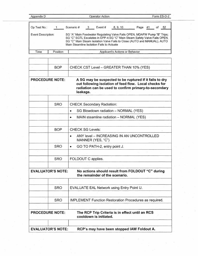
Appendix D
Op Test No.:
operator Action Form ES-D-2
_8....,_9...., 1_0 Page i2.- of _5_2__11
Event Description: SG "A" Main Feedwater Regulating Valve Fails OPEN, MDAFW Pump "B" Trips;SG "c'" SGTL Escalates in EPP-4;SG "C" Main Steam Safety Valve Fails OPEN,SG "C" Main Steam Isolation Valve Fails to Close (AUTO and MANUAL), AUTOMain Steamline Isolation Fails' to Actuate
Time Position Applicant's Actions or Behavior
BOP CHECK CST Level- GREATER THAN 10% (YES)
PROCEDURE NOTE: A SG may be suspected to be ruptured if it fails to dryout following isolation of feed flow. Local checks forradiation can be used to confirm primary-to-secondaryleakage.'
SRO CHECK Secondary Radiation:
• SG Blowdown radiation - NORMAL (YES)
• MAIN steamline radiatiqn.- NORMAL (YES)
BOP CHECK SG Levels:
• ANY level-INCREASING IN AN UNCONTROLLEDMANNER (YES, "C")
SRO • GO TOPATH-2, entry point J.
SRO FOLDOUT C applies.
EVAL.ltATOR'S NOTE: No actions should result from FOLDOUT "C" duringthe remainder of the scenario.
SRO EVALUATE EAL Network using Entry Point U.
SRO IMPLEMENT Function Restoration'Procedures as required.
PROCEDURE NOTE: The RCP Trip Criteria is in effect until an RCScooldown' is initiated.
EVALUATOR'S NOTE: RCP's may have been stopped lAW Foldout A.
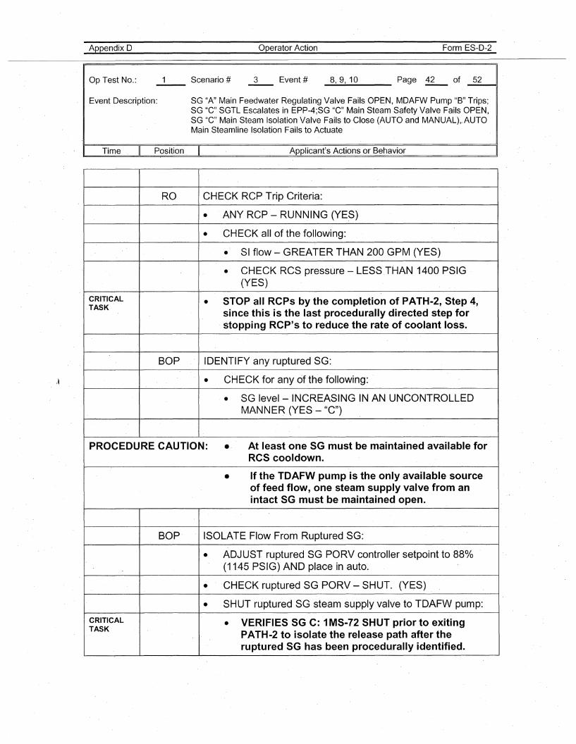
Appendix 0
Op Test No.:
Operator Action Form ES-D-2
_8......,_9__, 1_0 Page ~ of _5_2----11
Event Description:
Time II Position
SG "A" Main Feedwater Regulating Valve Fails OPEN, MDAFW Pump "B" Trips;SG "G" SGTL Escalates in EPP-4;SG "G" Main Steam Safety Valve Fails OPEN,SG "G" Main Steam Isolation Valve Fails toGlose (AUTO and MANUAL)" AUTOMain Steamline Isolation Fails to Actuate
Applicant's Actions or Behavior
RO CHECK RCP Trip Criteria:
• ANY RCP - RUNNING (YES)
• CHECK all of the following:
• SI flow - GREATER THAN 200 GPM (YES)
• CHECK RCS pressure - LESS THAN 1400 PSIG(YES)
CRITICAL • STOP all RCPs by the completion of PATH-2, Step 4,TASK
since this is the last procedurally directed step for, stopping RCP's to reduce the rate of coolant loss.
BOP ID,ENTIFY any ruptured SG:
• CHECK for any of the following:
• SG level - INCREASING IN AN UNCONTROLLEDMANNER (YES - "C")
PROCEDURE CAUTION: .' At least one SG must be maintained available forRCS cooldown.
• If the TDAFW pump is the only available sourceof feed flow, one steam supply valve from anintact SG must be maintained open.
BOP 'ISOLATE Flow From Ruptured SG:
• ADJUST ruptured SG PORV controller setpoint to 880/0(11.45 PSIG) AND place in auto'.
• ' 'CHECK ruptured SG PORV - SHUT. (YES)
• SHUT ruptured SG steam supply valve to TD,AFW pump:
CRITICAL • VERIFIES SG C: 1MS-72 SHUT prior to eXitingTASK
PATH-2 to isolate the release path after theruptured SG has been procedurally identified.
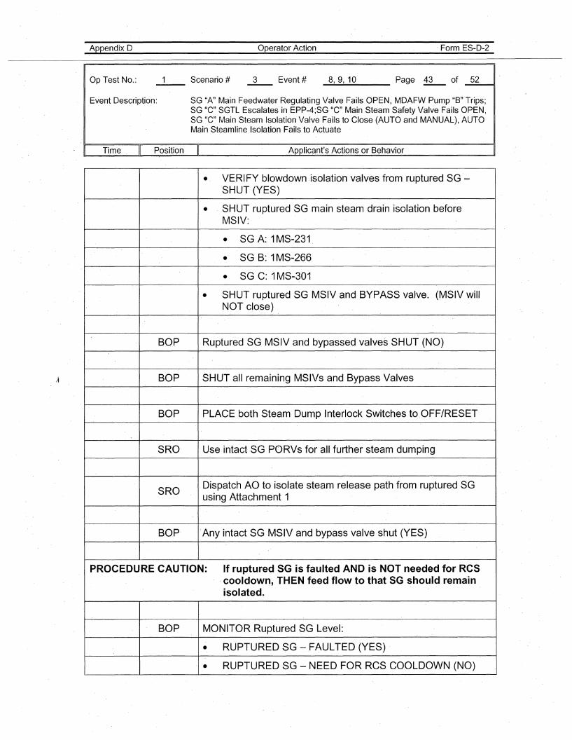
Appendix D
Op Test No.:
operator Action Form ES-D-2
_8.....,_9....,1_0 Page ~ of _5_2----(1
Event Description: SG "A" Main Feedwater Regulating Valve Fails OPEN, MDAFW Pump "B" Trips;SG "C" SGTL Escalates' in EPP-4;SG "C" Main Steam Safety Valve Fails OPEN,SG "C" Main Steam Isolation Valve Fails to Close (AUTO and MANUAL), AUTOMain Steamline Isolation Fails to Actuate
. I Time Position Applicant's Actions or Behavior
\~
• VERIFY blowdown ,isolation'valves from ruptured SG -SHUT (YES)
• . SHUT ruptured SG main steam drain isol'ation beforeMSIV:
• SG A: 1MS-231
• SG B: 1MS-266
• SG C: 1MS-301
• SHUT ruptured SG MSIV and BYPASS valve. (MSIVwiliNOT close)
BOP RupturedSG MSIV and bypassed valves SHUT (NO)
BOP SHUT all remaining MSIVs and Bypass Valves
BOP PLACE both Steam Dump Interlock Switches to.OFF/RESET
SRO Use intact SG PORVs for all further steam dumping
SRODispatch AO to isolate steam release path from ruptured SGusing Attachment 1
BOP 'Any intact SG MSIV and bypass valve shut (YES)
PROCEDURE CAUTION: If ruptured SG is faulted AND is NOT needed for RCS,cooldown, THEN feed flow to that SG should remainisolated.
BOP MONITOR Ruptured SG LeveJ:
• RUPTURED SG -FAULTED (YES)
• RUPTURED SG - NEED FOR RCS COOLDOWN (NO)
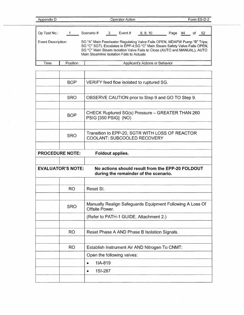
Appendix D
Op Test No.:
operator Action Form ES-D-2
_8..-,_9-..,1_0 Page .~ of _5_2----11
Event Description: SG "A" Main Feedwater Regulating Valve Fails OPEN, MDAFW Pump "B" Trips;SG "C" SGTL Escalates in EPP-4;SG "e" Main Steam Safety Valve Fails OPEN,SG "C" Main Steam Isolation Valve Fails to Close (AUTO and MANUAL), AUTOMain Steamline Isolation Fails to Actuate
Time Position Applicant's Actions or Behavior
BOP VERIFY feed flow isolated to ruptured SG.
SRO OBSERVE CAUTION prior to Step 9 and GO TO Step 9.
BOPCHECK Ruptured SG(s) Pressure - GREATER THAN 260PSIG [350 PSIG] (NO)
SROTransition to EPP-20, SGTR WITH LOSS,OF REACTORCOOLANT: SUBCOOLED RECOVERY
PROCEDURE NOTE: Foldout applies.
EVALUATOR'S NOTE: No actions should result from the EPP-20 FOLDOUTduring the remainder of the scenario.
RO Reset SI.
SROManually Realign Safeguards Equipment Following A Loss OfOffsite Power.
(Refer to PATH-1 GUIDE, Attachment 2.)
RO Reset Phase A AND Phase B Isolation Signals.
RO Establish Instrument Air AND Nitrogen To CNMT:
Open the following valves:
• 11A-819
• 1SI-287
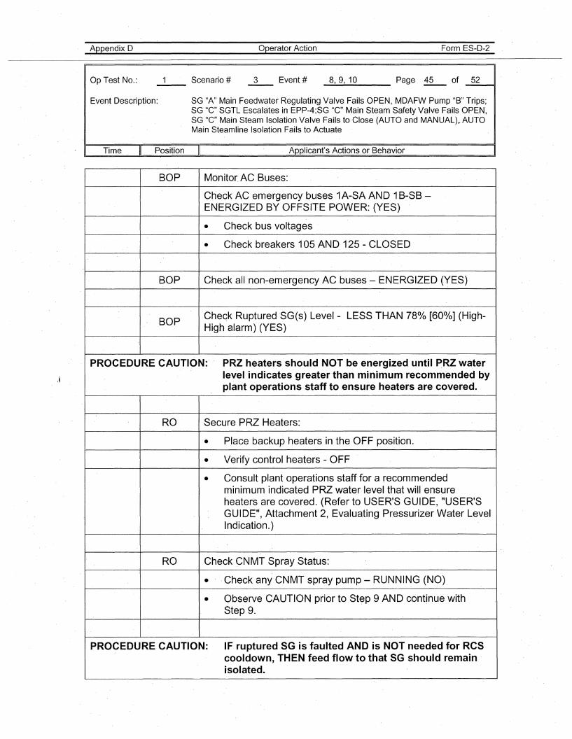
Appendix D
Op Test No.:
operator Action Form ES-D-2
_8..-,_9....,1_0 Page ~ of _5_211
Event Description: SG "A" Main Feedwater Regulating Valve Fails OPEN, MDAFW Pump "B" Trips;SG "C" SGTL Escalates in EPP-4;SG "C" Main Steam Safety Valve Fai.ls OPEN,SG "C" Main Steam Isolation Valve Fails to·Close (AUTO and MANUAL),. AUTOMain Steamline Isolation Fails to Actuate
Time Position Applicant's Actions or Behavior
BOP Monitor. AC Buses:
Check AC emergency buses 1A-SA AND 1B-SB-ENERGIZED BY OFFSITE POWER: (YES)
• Check bus voltages
• Check breakers 105 AND 125 - CLOSED
BOP Check all non-emergency AC buses - ENERGIZED (YES)
BOPCheck RupturedSG(s) Level - LESS THAN 78% [60·%] (High-High alarm) (YES)
·PROCEDURE CAUTION: PRZ heaters should NOT be energized until PRZ waterlevel indicates greater than minimum recommen.ded byplant operations staff to ensure heaters are covered.
RO Secure PRZ Heaters.:
• Place backu.p heaters in the OFF position.
• Verify control heaters - OFF
• Consult plant operations staff fora recommendedminimum indicated PRZ water level that will ensureheaters are covered. (Refer to USER'S GUIDE, "USER'SGUIDE", Attachment 2, Evaluating Pressurizer Water LevelIndication.)
RO Check CNMT Spray Status:
• .Check any CNMT spray pump - RUNNING (NO)
• Observe CAUTION prior to Step 9 AND continue withStep 9.
PROCEDURE CAUTION: IF ruptured SG is faulted AND is NOT needed for RCScooldown, THEN feed flow to that SG should remain·isolated.
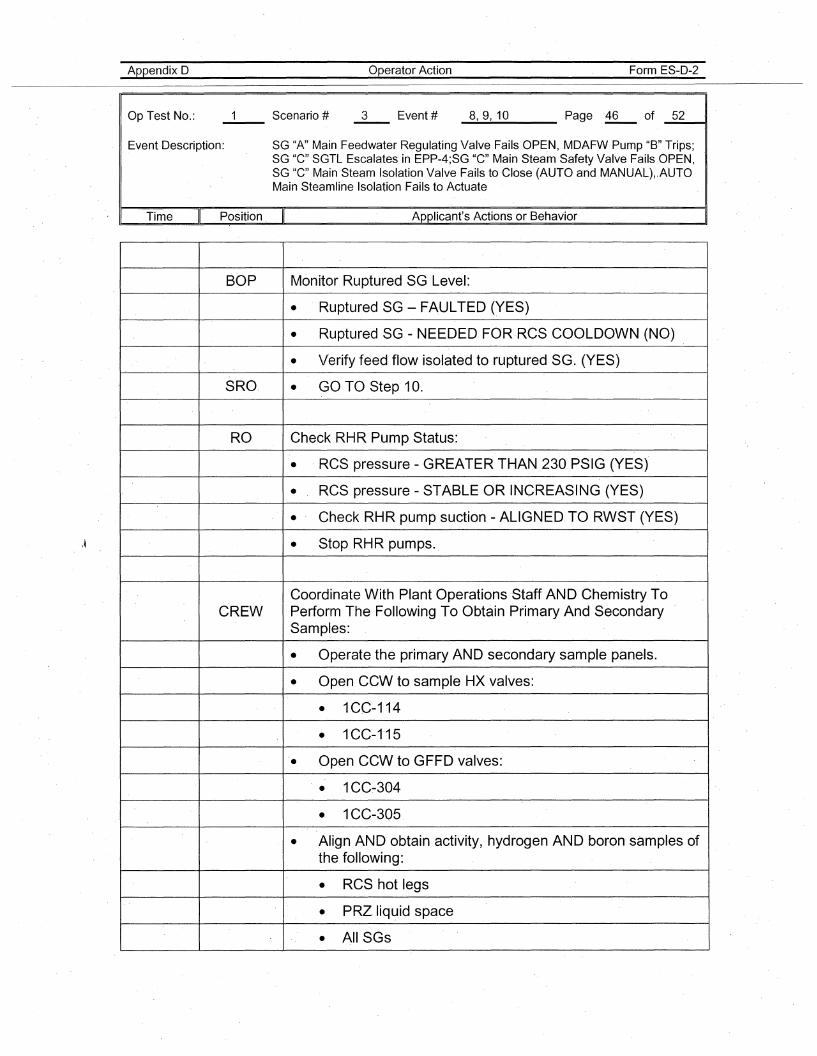
Appendix D
Op Test No.:
Operator Action Form ES-D-2
_8.......,_9-..,1_D Page~ of _5_2--41
Event Description: SG "A" Main Feedwater Regulating Valve Fails OPEN, MDAFW Pump "B" Trips;SG "c" SGTL Escalates in EPP-4;SG "c" Main Steam Safety Valve Fails OPEN,SG "C" Main Steam Isolation Valve Fails to Close (AUTO and MANUAL)"AUTOMain Steamline Isolation Fails to Actuate
. I Time Position Applicant's Actions or Behavior
\~
BOP Monitor Ruptured SG Level:
• Ruptured SG - FAULTED (YES)
• Ruptured SG - NEEDED FORRCS COOLDOWN (NO)
• Verify feed flow isolated to ruptured SG. (YES)
SRO, • GO TO Step' 10.
RO Check RHR Pump Status:
• ' RCS pressure - GREATER THAN 230 PSIG (YES)
• RCS pressure - STABLE OR INCREASING (YES)
• Check RHR pump suction - ALIGNED TO RWST (YES)
• Stop RHR pumps.
Coordinate With Plant Operations 'Staff AND Chemistry ToC'REW Perform The Following To Obtain Primary And Secondary
Samples:
• Operate the primary AND sec'ondary sample panels.
• Open CCW to sample HX ,valves:
• 1CC-114
• 1CC-1'15
• Open CCW to GFFD valves:
• 1CC~304
• 1CC-305
• Align AND' obtain activity, hydrogen AND boron'samplesofthe following:
• RCS hot legs
• PRZ liquid space
• AIISGs
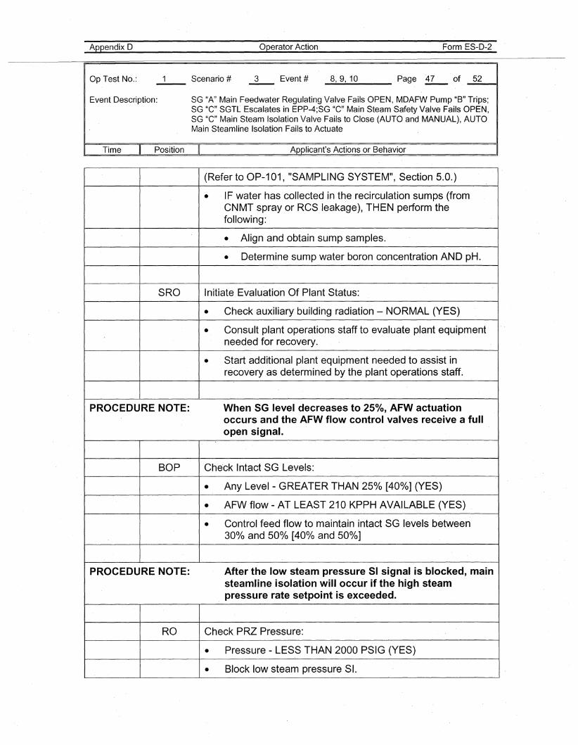
Appendix D
Op Test No.: Scenario #-- 3
operator Action
Event #
Form ES-D-2
_8__,_9__,1_0 Page £- of _5_2--11
Event Description: SG "A" Main Feedwater Regulating Valve Fails OPEN, MDAFW Pump "B" Trips;SG "C" SGTL Escalates in EPP-4;SG "C" Main Steam Safety Valve Fails OPEN,SG "C" Main Steam Isolation Valve Fails to Close (AUTO and MANUAL), AUTOMain Steamline Isolation Fails to Actuate
Time Position Applicant's Actions or Behavior
(Refer to OP-101, "SAMPLING SYSTEM", Section 5.0.)
• IF water has collected in the recirculation sumps (fromCNMT spray or RCS leakage), THEN perform thefollowing:
• Align and obtain sump samples.
• Determine sump water boron concentration AND pH.
SRO Initiate Evaluation Of Plant Status:
• Check auxiliary' building radiation - NORMAL (YES)
• Consult plant operations staff to evaluate plant equipmentneeded for recovery.
• Start additional plant equipment needed to assist inrecovery as determined by the plant operations staff.
PROCEDURE NOTE: When SG level decreases to 250/0, AFW actuationoccurs and the AFW flow control valves receive a fullopen signal.
BOP Che'ck Intact SG Levels:
• Any Level - GREATER THAN 250/0 [400/0] (YES)
• AFW flow - AT LEAST 210 KPPH AVAILABLE (YES)
• Control feed flow to maintain intact SG levels between30% and 50% ,[40% and 50%]
PROCEDURE NOTE: After the low steam pressure SI signal is blocked, mainsteamline isolation will occur if the high steampressure rate setpoint is exceeded.
RO Check, PRZ Pressure:
• Pressure - LESS THAN 2000 PSIG (YES)
• Block low steam pressure SI.
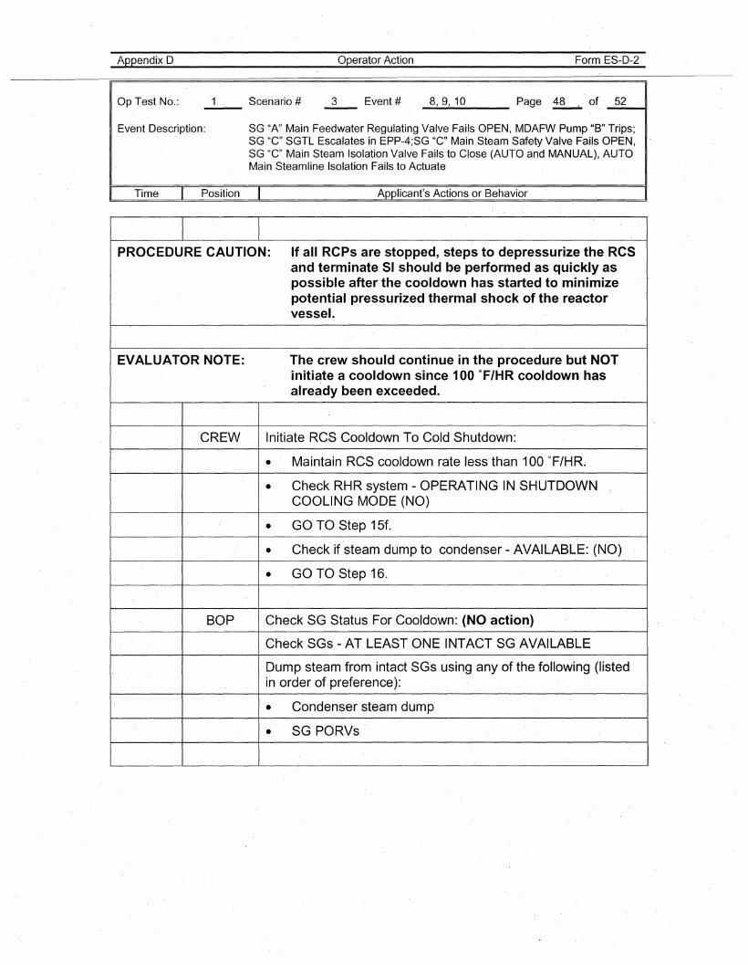
Appendix D
Op Test No.: 3
Operator Action
Event #
Form ES-D-2
_8..-,_9,....1_0 Page .~ of _5_211
Event Description: SG "A" Main Feedwater Regulating Valve Fails OPEN, MDAFW Pump "B" Trips;SG "C" SGTL Escalates in EPP-4;SG "C" Main Steam Safety.Valve Fails OPEN,SG "C" Main Steam Isolation Valve Fails to Close (AUTO and MANUAL), AUTOMain Steamline Isolation Fails to Actuate
Time Position Applicant's Actions or Behavior
PROCEDURE CAUTI·ON: If all RCPs are stopped, steps to depressurize the RCSand terminateSI should be performed as quickly aspossible after the cooldown has started to minimizepotential pressurized thermal shock of the reactor.vessel.
EVALUATOR NOTE: The crew should continue in the procedure but NOTinitiate a cooldown since 100 °F/HR cooldown hasalready been exceeded.
CREW Initiate RCS Cooldown To Co.ld Shutdown:
• Maintain RCS cooldown rate less than 100 of/HR.
• Check RHR system - OPERATING IN SHUTDOWNCOOLING MODE (NO)
• GO TO Step 15f.
• Check' if steam dump to condenser - AVAILABLE: (NO)
• GO TO Step 16.
BOP Check SGStatus For Cooldown: (NO action)
Check SGs - AT LEAST ONE INTACT SG AVAILABLE
Dump steam from intact SGs using any of the following (listedin order of preference):
• Condenser'steam dump
• SG PO·RVs
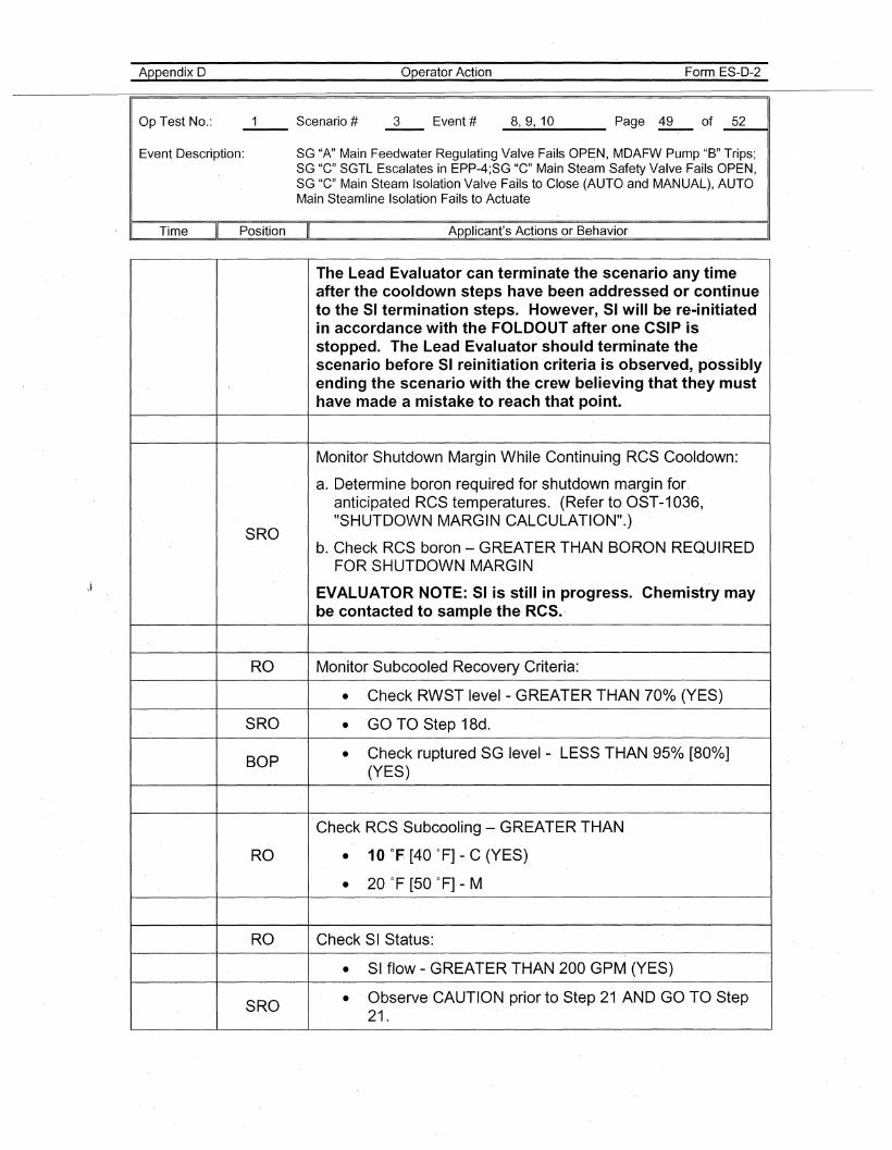
Appendix D
Op Test No.:
operator Action Form ES-D-2
_8......,_9...., 1_0___ Page .12.- of _5_2---41
Event Description: SG "A" Main Feedwater Regulating Valve Fails OPEN, MDAFW Pump "B" Trips;SG "C" SGTL Escalates in EPP-4;SG "C" Main Steam Safety Valve Fails OPEN,SG "C" Main Steam Isolation Valve Fails to Close (AUTO and MANUAL), AUTOMain Steamline Isolation Fails to Actuate
. I Time Position
SRO
RO
SRO
BOP
Applicant's Actions or Behavior
The Lead Evaluator can terminate the scenario any timeafter the cooldown steps have been addressed or continueto the 51 termination steps. However, 51 will be re-initiatedin accordance with the FOLDOUT after one C51P isstopped. The Lead Evaluatorshould terminate thescenario before 51 reinitiation criteria is observed, possiblyending the scenario with the crew believing that they musthave made a mistake to reach that point.
Monitor Shutdown Margin While Continuing RCS Cooldown:
a. Determine boron required for shutdown margin for.anticipated RCS temperatures. (Refer to OST-1036,"SHUTDOWN MARGIN CALCULATION".)
b. Check RCS boron - GREATER THAN BORON REQUIREDFOR SHUTDOWN MARGIN
EVALUATOR NOTE: 51 is still in progress. Chemistry maybe contacted to sample the RC5.
Monitor Subcooled Recovery Criteria:
• Check RWST level - GREATER THAN 700/0 (YES)
• GO TO Step 18d.
• Check ruptured SG level - LESS THAN 950/0 [800/0](YES)
Check RCS Subcooling - GREATER THAN
RO • 10 of [40 OF] - C (YES)
• 20°F [50 OF] - M
RO Check SI Status:
• SI flow - GREATER·THAN 200 GPM (YES).
SRO • Observe CAUTION prior to Step 21 AND GO TO Step21.
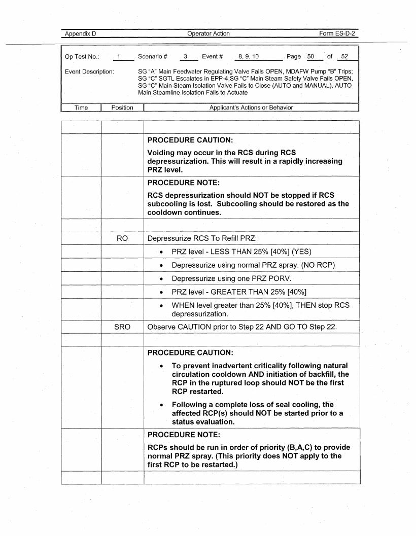
Appendix D
Op Test No.:
Operator Action Form ES-D-2
_8......,_9-..,1_0 , Page .29-- of _5_2----11
Event Description: SG "A" Main Feedwater R~gulating Valve Fails OPEN, MDAFW Pump "B" Trips;SG "c,,· SGTL Escalates in EPP-4;SG "c" Main Steam Safety Valve Fails OPEN,SG "c" Main Steam Isolation Valve Fails to Close (AUTO and MANUAL), AUTOMain Steamline Isolation Fails to Actuate
Time Position Applicant's Actions or Behavior
PROCEDURE CAUTION:
Voiding may occur in the RCS during RCSdepressurization. This will result in a rapidly increasingPRZ level.
PROCEDURE NOTE:
RCS depressurization should NOT be stopped if RCSsubcoolingis lost. Subcooling·should be restored as thecooldown continues.
RO Depressurize RCSTo Refill PRZ:.. PRZ level - LESS THAN 250/0 [400/0] (YES)
• De·pressurize using normal PRZ spray. (NO RCP)
• Depressurize using one PRZ PORV.·
• PRZ level - GREATER THAN 25°A> [400/0]
• WHEN level greater than·25% [40%], THEN stop RCS .depressurization.
SRO Observe ·CAUTION prior to Step 22 AND. GO TO Step 22.
PROCEDURE CAUTION:
• To prevent inadvertent criticality following naturalcirculation cooldown AND initiation of backfill, theRCP in the ruptured loop should NOT be the firstRCP restarted.
• Following a complete loss of seal·cooling, tn~affected RCP(s) should NOT be started prior to astatus evaluation.
PROCEDURE NOTE:
RCPs should be run in order of priority (B,A,C) to providenormal PRZ spray. (This priority does NOT apply -to thefirst RCP to be restarted.)
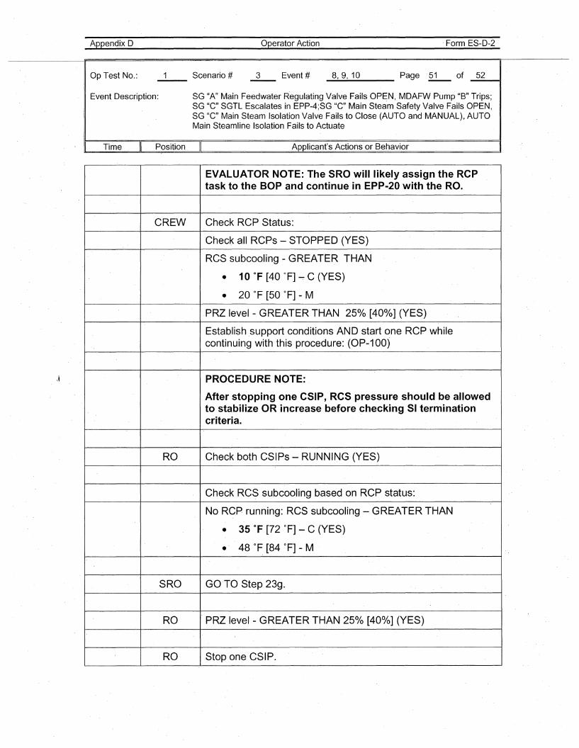
Appendix D
Op Test No.:
Operator Action Form ES-D-2
_8......,_9....,1_0 Page 21....- of _5_2~,
Event Description: SG "A" Main Feedwater Regulating Valve Fails OPEN, MDAFW Pump "B" Trips;SG "C" SGTL Escalates in EPP-4;SG "C" Main Steam Safety Valve Fails OPEN,SG "C" Main Steam Isolation Valve Fails to·Close (AUTO and MANUAL),. AUTOMain Steamline Isolation Fails to Actuate
Time Position Applicant's Actions or Behavior
EVALUATOR NOTE: T.he SROwililikely assign the RCPtask to the BOP and continue in EPP-20 with the RO.
CREW Check RCP Status:
Check all RCPs - STOPPED (YES)
ReS subcooling - GREATER THAN
• 10 of [40 OF] ~ C (YES)
• 20 OF [50 OF] - M
PRZ level - GREATER THAN 250/0 [40%] (YES)
Establish support conditions AND start one RCP whilecontinuing with this procedure: (OP-100)
PROCEDURE NOTE:
After stopping one CSIP, ReS pressure should be allowedto stabilize OR increase before checking 51 terminationcriteria.
RO Check both CSIPs - RUNNING (YES)
Check RCS subcooling based on RCP status:
No RCP running: RCS subcooling - GREATER THAN
• 35 of [72 OF] - C (YES)
• 48 0 F [84 ° F] - M
SRO GO·TO Step 23g.
RO PRZ level - GREATER THAN 25% [40%] (YES)
RO Stop one CSIP.
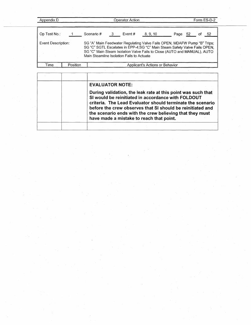
Appendix D
Op Test No.:
Operator Action
3 ' Event #
Form ES-D-2
_8.....,_9...., _10 Page '~of" _ 5_2__11
Event Description: SG "A" Main Feedwater Regulating Valve Fails OPEN, MDAFW Pump "B" Trips;SG "C" SGTL Escalates in EPP-4;SG "C" Main Steam Safety Valve Fails OPEN,SG "C" Main Steam Isolation Valve Fails to Close (AUTO and MANUAL), AUTOMain Steamline Isolation Fails to Actuate
Time Position Applicant's Actions or Behavior
EVALUATOR NOTE:
During validation, the leak rate at this point was such thatSI would be reinitiated 'in accordance with FOLDOUTcriteria. The Lead Evaluator should terminate the scenariobefore the crew observes that SI should be reinitiated andthe scenariQ ends with the crew b,elieving that they musthave made a mistake to reach that point.
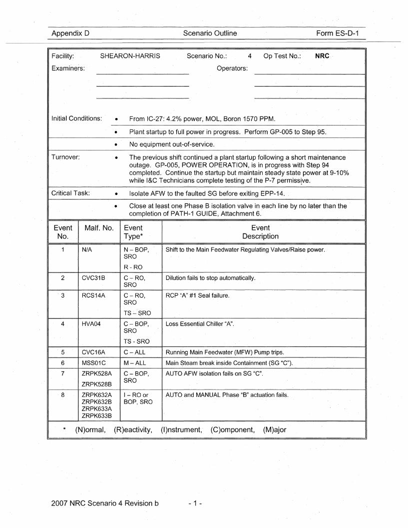
Appendix D
Facility.:
Examiners:
SHEARON-HARRIS
Scenario Outline
Scenario No.:
Operators:
4 Op Test No.:
Form ES-D~1
NRC·
Initial Conditions: • From IC-27: 4.20/0 power, MOL, Boron 1570 PPM.
• Plant startup to full power in progress. Perform GP-005 to Step 95.
• No equipment out-of-service.
Turnover:
Critical Task:
• The previous shift continued a plant startup following a short maintenanceoutage. GP-005, POWER OPERATION, is in progress. with Step 94completed. Continue the startup but maintain steady state power at 9-10%while I&C Technicians complete testing of the P-7 permisstve.
• Isolate AFW to the faulted SG before exiting EPP-14.
• Close at least one Phase B isolation valve in each line by no ·Iater than thecompletion of PATH-1 GUIDE, Attachment 6.
Event Malt. No.No.
1 N/A
2 CVC31B
3 RCS14A
4 HVA04
5 CVC16A
6 MSS01C
7 ZRPK528A
ZRPK528B
8 ZRPK632AZRPK632BZRPK633AZRPK633B
Event.Type*
N - BOP,SRO
R-RO
C-RO,SRO
C,- RO,SRO
TS~SRO
C-BOP,SRO
TS - SRO
C-ALL
M-ALL
.C - BOP,SRO
1- RO orBOP, SRQ
EventDescription
Shift to the Main Feedwater Regulating Valves/Raise power.
pilution fails to stop automatically.
RCP '·'A". #1 Seal failure.
Loss Essential Chiller "A".
Running Main Feedwater (MFW) Pump trips.
Main ~team break inside Containment {SG "C").
AUTO AFW isolation fails on SG "C".
AUTO and MANUAL Phase "B" actuation fails.
* (N)ormal, (R)eactivity, (I)nstrument, (C)omponent, (M)ajor
2007 NRC Scenario 4 Revision b - 1 -
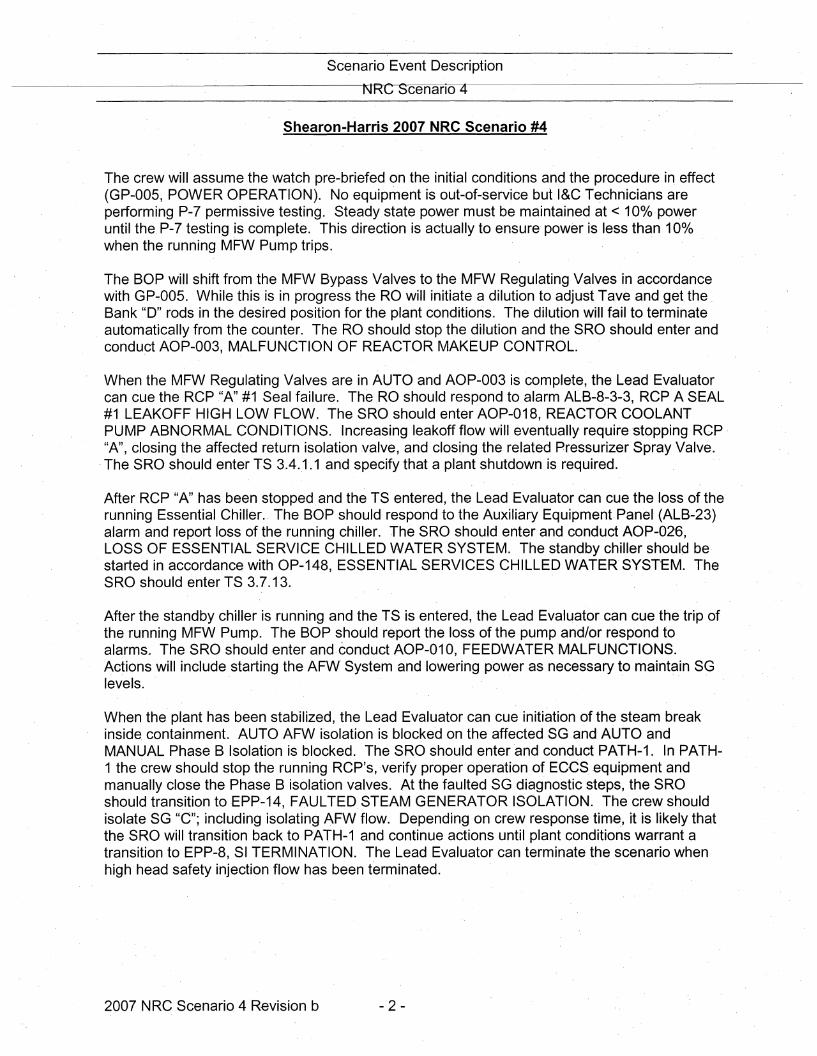
Scenario Event Description
NRC Scenano 4
Shearon-Harris 2007 NRC Scenario #4
The· crew will assume the watch pre-briefed on the initial conditions and the procedure in effect(GP-005, POWER OPERATION). No equipment is out-of-service but I&C T~chnicians areperforming P-7 permissive testing. Steady state power must be maintained at < 10%poweruntil the P-7 testing is complete. This direction is actually to ensure' power is less than 100/0when the running MFW Pump trips.
The BOP will shift from the MFW Bypass Valves to theMFW Regulating Valves in accordancewith GP~005. While this is in progress the RO will initiate a dilution to adjust Tave and get theBank "D" rods in the desired position for the plant conditions. The dilution will fail to terminateautomatically from the counter. The RO should stop the dilution and the S.RO should enter andconduct AOP-003, MALFUNCTION OF REACTOR MAKEUP CONTROL.
When the MFW Regulating Valves are in AUTO and AOP-003 is complete, the Lead Evaluatorcan cue the RCP "A" #1 Seal failure. TheRO should respond to alarm ALB-8-3-3, RCP A SEAL#1 LEAKOFF HIGH LOW FLOW. The· SRO should enter AOP-018, REACTOR COOLANTPUMP ABNORMAL CONDITIONS. Increasing leakoff flow will eventually require stopping Rep"A", closing the affected return isolation valve, and closi.ng the related Pressurizer Spray Valve.
.The SRO should enter TS 3.4 ..1.1 and specify that a plant shutdown is required.
After RCP "A" has been stopped. and the TS entered, the Lead Evaluator can cue the loss of therunning Essential Chiller. The BOP should· respond to the Auxiliary Equipment.Panel (ALB-23)alarm and report loss of the running chiller. The SRO should enter and conduct AOP-026,LOSS OF ESSENTIAL SERVICE C'HILLED WATER SYSTEM. The standby chiller should bestarted in accordance with OP-148, ESSENTIAL SERVICES CHILLED WATER SYSTEM. TheSRO should enter TS 3.7.13.
After the standby chiller is funning and the TS is entered, the Lead Evaluator can cue the trip ofthe funning MFW Pump. The BOP should report the loss of the pump an'd/or respond toalarms. The SRO should ·enter and.conduct AOP-010, FEEDWATERMALFUNCTIONS.Actions will include starting the AFW System and lowering power as necessary to maintain SGlevels.
When the plant has been stabilized, the Lead Evaluator can cue initiation of the steam breakinside containment. AUTO AFW isolation is blocked on the affected SG and AUTO andMANUAL Phase B Isolation is blocked. The SR.O should enter and conduct PATH-1. In PATH1 the crew should stop the running RCP's, :verify proper operation ,of ECCS .equipment andmanually close the Phase B isolation valves. At the faulted SG diagnostic steps, the SROshould transition to EPP-14, FAULTED STEAM GENERATOR ISOLATION'. The crew shouldisolate SG "e"; including isolating AFW flow. Depending on crew response time, it is likely thatthe SRO will transition back to PATH-1 and continue actions until plant conditions warrant atransition to EPP-8, SI TERMINATION. The Lead Evaluator can terminate the scenario whenhigh head safety injection flow has been termin·ated.
2007 NRC Scenario 4 Revision b - 2 -
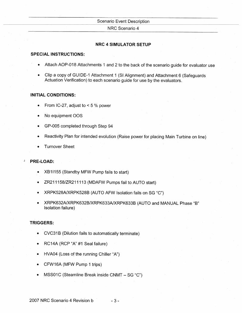
Scenario .Event Description
NRC Scenario 4
NRC 4 SIMULATOR SETUP
SPECIAL INSTRUCTIONS:
• Attach AOP~018 Attachments 1 and 2 to the back of the scenario guide for evaluator use
• Clip a copy of GUIDE-1 Attachment 1 (SI Alignment) and Attachment 6 (SafeguardsActuation Verification) to each scenario guide for use by the evaluators.
INITIAL CONDITIONS:
• From IC-27, adjust to < 5 0/6 power
• No equipment O·OS
• GP-005 completed through Step 94
• Reactivity Plan for intend·ed evolution (Raise power for placing Main Turbine on line)
• Turnover Sheet
It PRE-LOAD:
• XB11155 (Standby MFW Pump fails to start)
• ZR211158/ZR211113 (MDAFW Pumps fail to AUTO start)
• XRPK528A1XRPK528B (AUTO AFW Isolation fails 'on SG "e")
• XRPK632A1XRPK632B/XRPK633A1XRPK633B (AUTO and MANUAL Phase "B"Isolation failure)
TRIGGERS:
• CVC31 B (Dilution fails to automatically terminate)
• RC14A (RCP "A" #1 Seal failure)
• HVA04 (Loss of the running Chiller "A")
• CFW16A (MFW Pump 1 trips)
• MSS01 C (Steamline Break inside CNMT - SG "C")
2007 NRC Scenario 4 Revisionb - 3 -
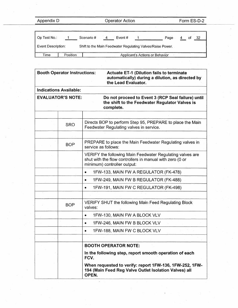
Operator·ActionAppendix D
Op 'Test No.:
Event Description:
Form ES-D-2
Page 4 .of 32----- ---II
Shift to the Main FeedwaterRegulating Valves/Raise·Power.
,. Time Position II Applicant's Actions or Behavior
Booth Operator Instructions: Actuate ET-1 (Dilution fails to terminateautomatically) during ·a dilution, as directed by'the Lead Evaluator.
Indications Available:
EVALUATOR'S NOTE: Do not proceed to Event 3 (RCP Seal failure) untilthe shift to the FeedwaterRegulator Valves iscomplete.
SRODirects BOP to perform Step. 95, PREPARE to place the MainFeedwater Regulating valves in service.
BOPP'REPARE to place the Main Feedwater Regulating valves inservice as' follows:
VERIFY the following Main Feedwater Regulating valves areshut with the flow controllers in manual with zero (0 or .minimum) controller output:
• 1FW-1.33, MAIN FW A REGULATOR (FK-478)
• 1FW-249, MAIN FW B REGULATOR (FK-488)
• 1FW'-191, MAIN FW C REGULATOR (FK-498)
BOPVERIFY SHUT the following Main Feed R.egulating Blockvalves:
• 1FW-130, MAIN FW A BLOCK VLV
• 1FW-246, MAI·N FW B BLOCKVLV
• 1FW-188, MAINFW C BLOCK VLV
BOOTH OPERATOR NOTE:
In the .following step, report smooth operation of eachFCV.
When 'requested to verify: report 1FW-136, 1FW~252, 1FW-194 (Main Feed Reg. Valve Outlet Isolation Valves) allOPEN.
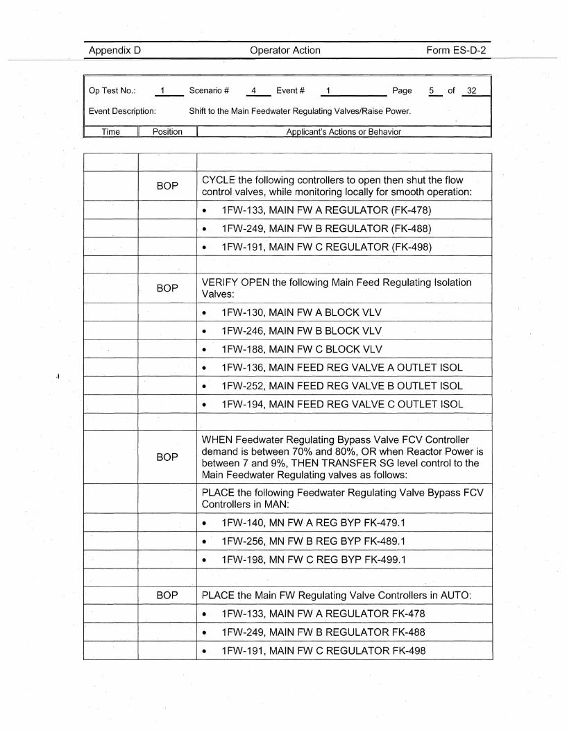
Appendix D Operator Action. Form ES-D-2
Op Test No.:
Event Description:
_____ Page 5 of _3_2--11
Shift to the Main Feedwater Regulating Valves/Raise' Power.
I Time Position Applicant's Actions or Behavior
BOPCYCLE the following cO'ntrollers to open then shut the flowcontrol valves, while monitoring locally for smooth operation:
• 1FW-133, MAIN FW A REGULATOR (FK-478)
• 1FW-249, MAIN FW B REGULATOR (FK-488)
• 1FW-191, MAIN FW C REGULATOR (FK-498)
BOPVERIFY OPEN the following Main Feed Regulating IsolationValves:
• 1FW-130, MAIN FW A BLOCK VLV
• 1FW-246, MAIN FW B BLOCK VLV.
• 1FW-188, MAIN FW C BLOCK VLV
• 1FW-136, MAIN FEED REG VALVE A OUTLET ISOL
• 1FW-252, MAIN FEED REG VALVE B OUTLET ISOL
• 1FW-194, MAIN FEED REG VALVE C OUTLET ISOL
WHEN Feedwater Regulating Bypass Valve FCV Controller
BOPdemand is between 700/0 and 80%, OR when Reactor Power isbetween 7 and '90/0, THEN TRANS'FER SG level control to th.eMain Feedwater Regulating valves as follows:
PLACE the following Feedwater Regulating Valve Bypass FCVControllers in MAN:
• 1FW-140, MN FW A REG BYP FK-479.1
• 1FW-256,.MN FW B REG BYP FK-489.1
• 1FW-198, MN FW C REG BYPFK-499.1
BOP PLACE the Main FW Regulating Valve Controllers in AUTO:
• 1FW-133, MAIN FW A REGULATOR FK-478
• 1FW-249, MAIN FW B REGULATOR FK-488
• 1FW-191, MAINFW C REGULATOR 'FK-498
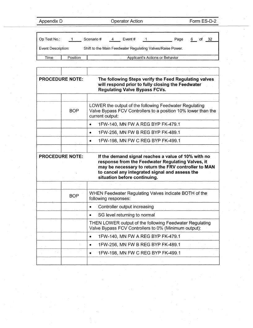
OperatorActionAppendix D
Op'Test No.:
Event Description:
Form ES-D-2
Page 6 of 32----- -----tl
Shift to the Main Feedwater' Regulating Valves/Raise Power.
I' Time Position Applicant's Actions or Behavior
PROCEDURE NOTE: The following Steps verify the Feed Regulating valveswill respond prior to fully closing the FeedwaterRegulating Valve Bypass FCVs. '
LOWER the output of the following FeedwaterRegulatingBOP Valve Bypass FCV Controllers to a position 10% lower than the
current output:
• 1FW-140, MN FW A REG BYP FK-479.1
• 1FW-256, MN FW B REG BYPFK-489.1
• 1FW-198, MN FW C REG BYP FK-499.1
PROCEDURE NOTE: If the' demand signal reaches a value ,of 100/0 with noresponse from the Feedwater Regulating Valves, itmay be necessary to return the FRV controller to MANto cancel any integrated signal and assess thesituation before continuing.
BOPWHEN Feedwater Regulating Valves indicate BOTH of thefollowing 'responses:
• Controller output increasing'
• SG level returning to normal
THEN LOWER output of the following Feedwater RegulatingValve Bypass FCV Controllers to 0%
' (Minimum output):
• 1FW-140, MN FW A REG BYP FK-479.1
• 1FW-256, MN FW B REG BYP FK-489~1
• 1FW-198, MN FW C REG BYP FK-499.1
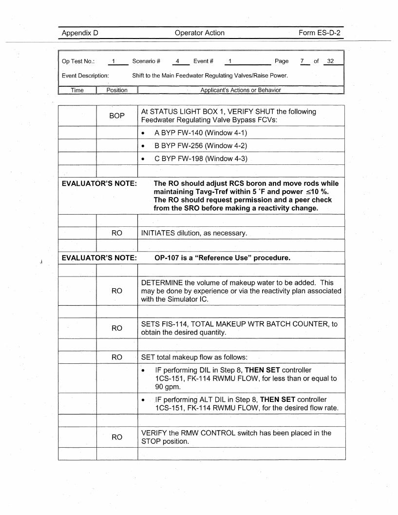
Appendix D Operator Action Form ES-D-2
Op Test No.:
Event Description:
_____ Page 7 of _3_2--11
Shift to the Main Feedwater Regulating Valves/Raise Power.
Time Position Applicant's Actions or Behavior
BOPAt STATUS LIGHT BOX 1, VERIFY SHUT the followingFeedwater Regulating Valve Bypass FCVs:
• A BYPFW-140 (Window 4-1)
• B BYP FW-256 (Window 4-2)
• C BYP FW-198 (Window 4-3)
EVALUATOR'S NOTE: The RO should adjust ReS boron and move rods whilemaintaining Tavg-Tref within 5 OF and power ~10 0/0.The RO should request permission and a peer checkfrom the SRO before making a reactivity change.
RO INITIATES dilution, as necessary.
EVALUATOR'S NOTE: OP-107 is a "Refere'nce Use" procedure.
DETERMINE the volume of makeup water to be added. This,RO may be done by experience or via the reactivity plan associated
with the Simulator IC.
ROSETS FIS-114,TOTAL MAKEUP WTR BATCH COUNTER, toobtain the desired quantity.
"
RO SET total makeup flow as follows:
• IF performing DIL in Step 8, THEN SET controller1CS-151, FK-114 RWMU FLOW, for less than or equal to90 gpm.
• ,IF performi'ng ALT DIL in Step 8, THEN SET controller1CS-151, FK-114 RWMU FLOW, for the desired flow rate.
ROVERIFY the RMW CONTROL switch has been placed in theSTOP position.
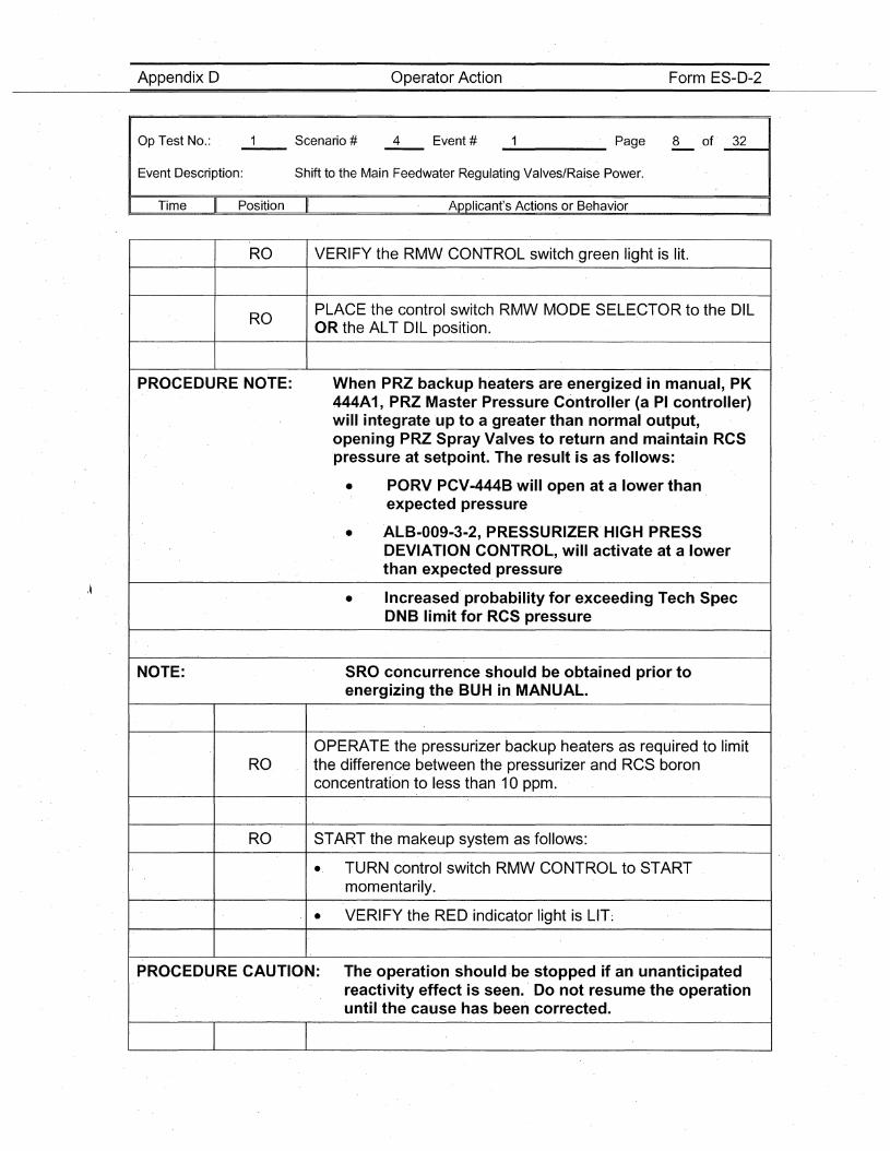
Appendix D Operator Action Form ES-D~2
Op Test No.:
Event Description:
_____ Page 8 of' _3_2----41
Shift to the Main Feedwater Regulating Valves/Raise Power.
Time II Position Applicant's Actions or Behavior . I
RO VERIFY the RMW CONTROL switch.green light is lit.
ROPLACE the control switch RMW MODE SELECTOR to the DILOR·the ALT DIL position.
P,ROCEDURE NOTE: When PRZ backup heaters are energized in manual, PK444A1, PRZ Master Pressure ControUer (a PI controUer)will integrate up to a greater than normal output,opening PRZ Spray Valves to return and maintain RCSpressure at setpoint. The result isas foUows:
• PORV PCV-444B wiU open at a lower thanexpected pressure
• ALB-009-3-2,PRESSURIZER' HIGH PRESSDEVIATION CONTROL, wiU activate at a lowerthan expected pressure
• Increased' probability for exceeding Tech SpecDNB limit for RCS pressure
NOTE: SRO concurrence should be obtained prior toenergizing the· BUH in MANUAL.
OPERATE the pressurizer backup heaters as required to limitRO the difference between the pressurizer and RCS boron
concentration to less than 10 ppm.
RO STA~T the makeup system as follows:
.. TURN control switch RMW CONTROL to STARTmomentarily.
• VERIFY the RED indicator light is LIT:
PROCEDURE CAUTION: The operation should·be stopped if an unanticipatedreactivity effect is seen. Do not resume the operationuntil the cause has been corrected.
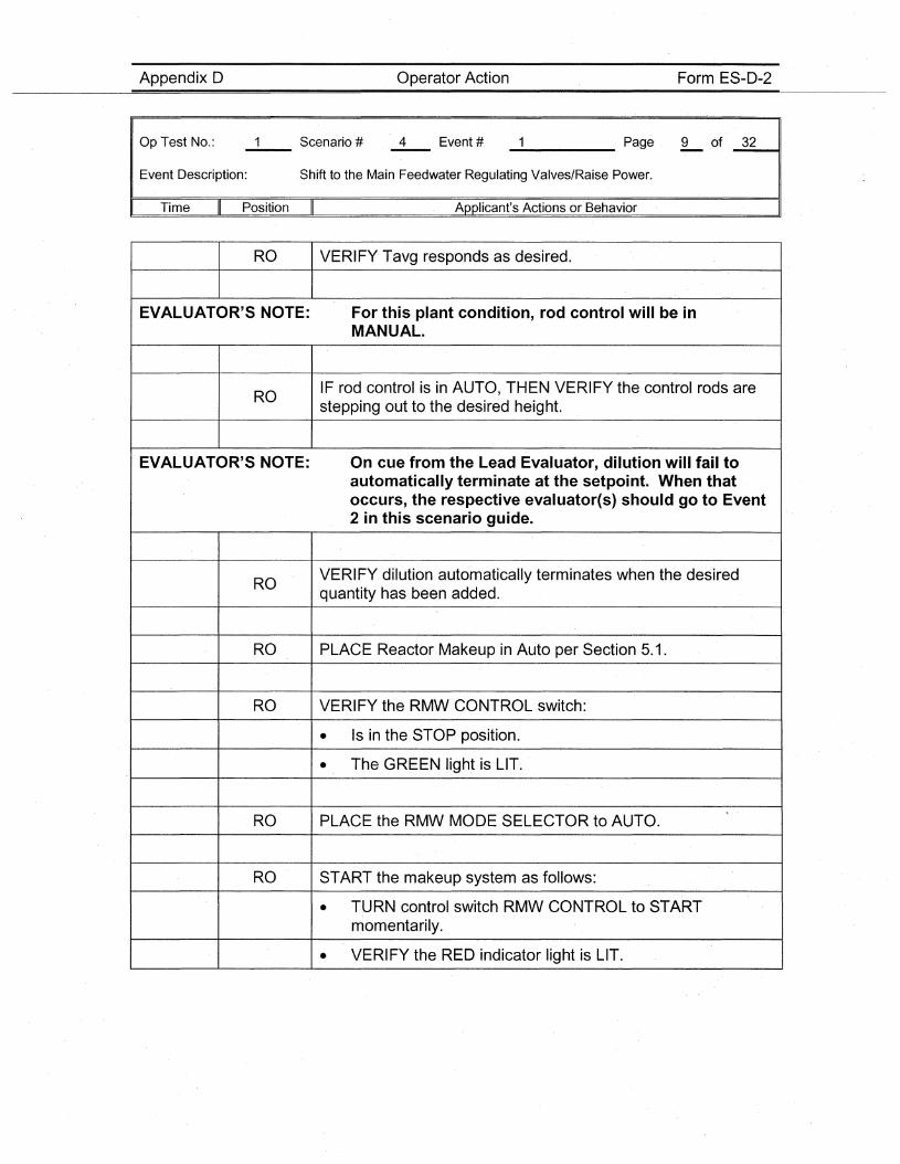
Appendix D Operator Action Form ES-D-2
Op'Test No.:
Event Description:
_____ Page 9 of _3_2---41
Shift to the Main FeedwaterRegulating Valves/Raise Power.
I' Time Position Applicant's Actions or Behavior
RO VERIFY Tavg responds as desired.
EVALUATOR'S NOTE: For this plant condition, rod control will be inMANUAL.
ROIF rod control is in AUTO, THEN VERIFY the control rods arestepping out to the desired height.
EVALUATOR'S NOTE: On cue from the Lead Evaluator, dilution will fail toautomatically terminate at the setpoint. When thatoccurs, the respective evaluator(s) should go to Event2 in this scenario guide.
ROVERIFY dilution automatically terminates when the desiredquantity has been added.
RO PLACE Reactor Makeup in Auto per Section 5.1.
RO VERIFY the RMW CONTROL switch:
• Is in the STOP position.
• The GREEN light is LIT~
RO PLACE the RMW MODE SELECTOR to AUTO.
RO START the makeup system as follows:
• TURN control switch RMW CONTROL to STARTmomentarily.
• VERIFY the RED indicator light is LIT.
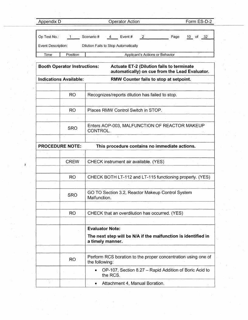
Appendix D Operator Action Form ES-D-2
Op Test No.:
Event Description: Dilution Fails to Stop Automatically
_2 Page 10 of _3_2__11
Time Position II Applicant's Actions or Behavior
Booth Operat<>.r Instructions: Actuate ET-2 (Dilution fails to terminateautomatically) on cue from the Lead Evaluator.
Indications Available: RMW Counter fails to stop at setpoint.
RO Recognizes/reports dilution has ·failed to stop.
RO Places RMW Control Switch in STOP.
SROEnters AOP-003, MALFUNCTION OF REACTOR MAKEUPCONTROL.
PROCEDURE NOTE: This procedure contains no immediate actions.
CREW CHECK instrument air available. (YES)
RO CHECK BOTH LT-112 and LT-115 functioning properly. (YES)
SROGO TO Section 3.2, R'eactor Makeup Control SystemMalfunction.
RO CHECK that an overdilution has occurred. (YES)
·Evaluator Note:
The next step will be N/A if the malfunction is identified i.na timely manner.
ROPerform RCS boration to the proper concentration' using one ofthe following:
• OP-107, Section 8.27 - Rapid Addition of Boric Acid tothe. RCS.
• Attachment 4, Manual Baration.
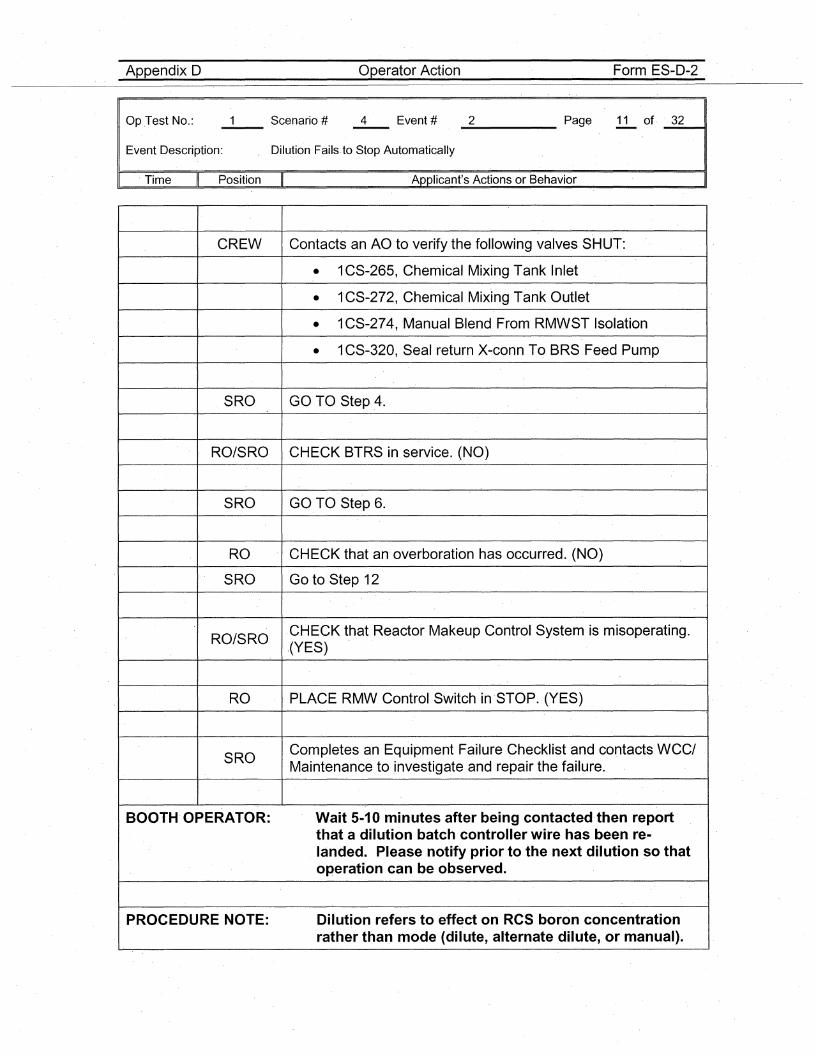
Appendix D Operator Action Form ES-D-2
Op .Test No.:
Event Description: , Dilution Fails.to Stop Automatically
_2 Page 11 of· _.3_2---11
Time II Position Applicant's Actions or Behavior
CREW Contacts an AO to verify the following valves SHUT:
• 1CS-265, Chemical Mixing Tank Inl"et
• tCS-272,Chemical Mixing Tank Outlet
• 1CS-274, ·Manual Blend From RMWST Isolation
• 1CS-320, Seal return X-conn To BRS Feed Pump
SRO GO TO Step 4.
RO/SRO CHECK STRS in service. (NO)
SRO GO TO Step 6.
RO CHECK that an· overboration has occurred. (NO)
SRO Go to Step 12
RO/SROCHECK that Reactor Makeup Control System is misoperating..(YES)
RO PLACE RMW ControJSwitch in STOP. (YES)
SROCompletes an Equipment Failure Checklist and contacts WCC/Maintenance to investigate and repair the failure.
BOOTH OPERATOR: Wait 5-10 minutes after being contacted then reportthat a dilution batch controller wire has been re-landed. Please notify prior to the next dilution so thatoperation can be observed.
PROCEDURE NOTE: Dilution refers to effect on RCS boron concentrationrather than mode (dilute, alternate dilute, or manual).
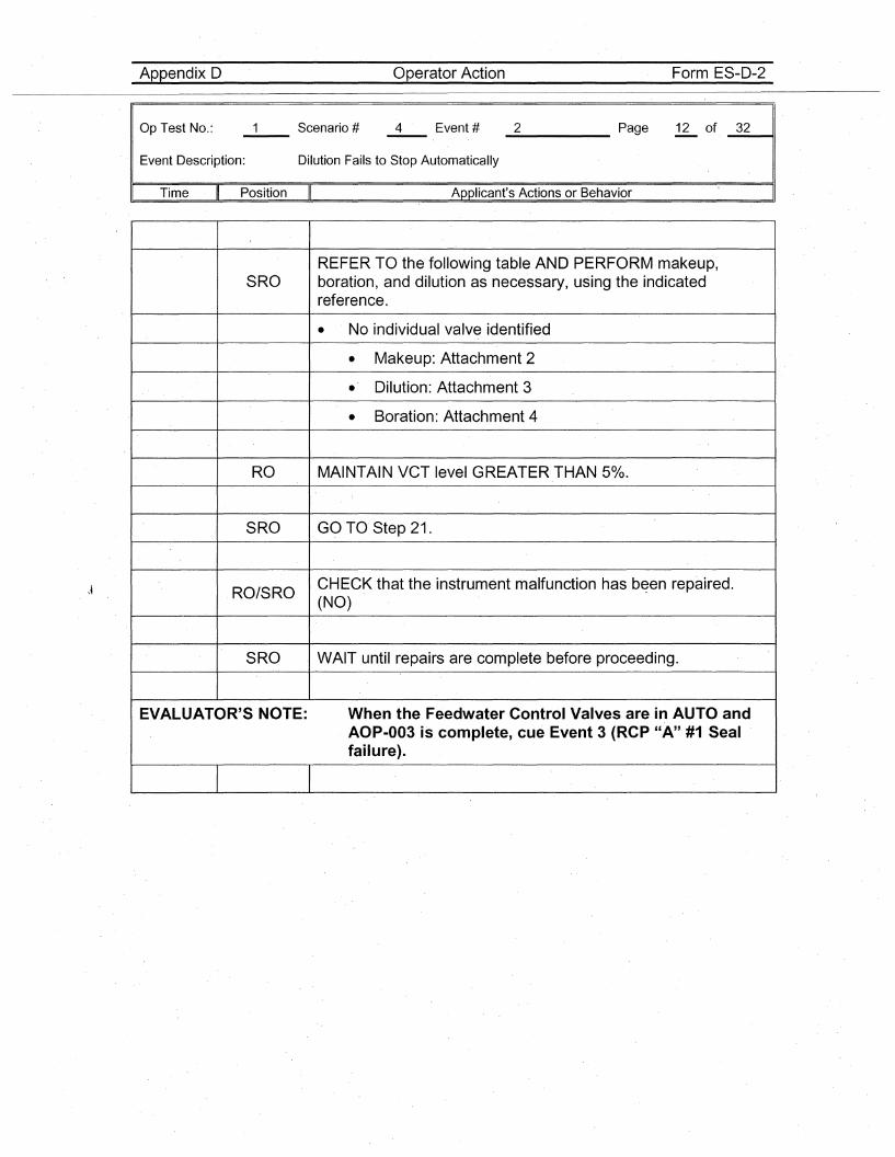
Appendix D Operator Action Form ES-D-2
Op Test No.:
Event Description: Dilution Fails to Stop Automatically
_2_____ Page 12 of _3_2----41
Time Position Applicant's Actions or Behavior
\~
REFER TO the following table AND PERFORM makeup,SRO boration, and dilution as necessary, using the indicated
reference.
• No individual valve identified
• Makeup: Attachment 2
• Dilution: Attachment 3
• Boration: Attachment 4
RO MAINTAIN VCT level GREATER THAN 50/0.
SRO GO TO' Step 21.
RO/SROCHECK that the instrument malfunction has b~en repaired.(NO)
SRO WAIT until repairs are complete before proceeding.
EVALUATOR'S NOTE: When the Feedwater Control Valves are in AUTO andAOP-003 is complete, cue Event 3 (RCP "A" #1 Sealfailure).
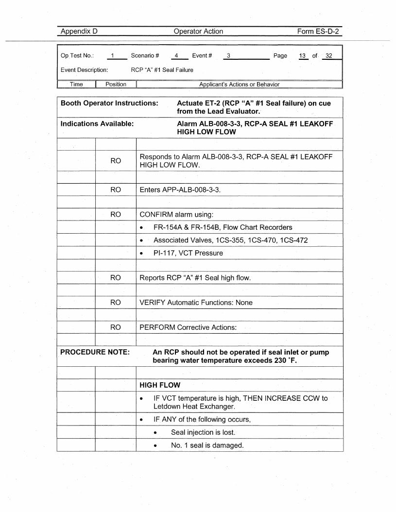
Appendix D Operator Action Form. ES-D-2
Op.Test No.:
Event Description: Rep "A" #1 Seal Failure
_3 Page 13 of· _3_2----11
. Time Position Applicant's Actions or Behavior
Booth Operator Instructions: Actuate ET-2 (RCP "A" #1 Seal failure) on cuefrom the Lead Evaluator.'
Indications Available: Alarm ALB-008-3-3,RCP-A SEAL #1 LEAKOFFHIGH LOW FLOW
ROResponds to Alarm ALB-008-3-3, RCP-A SEAL #1 LEAKOFFHIGH LOW FLOW.
RO Enters APP-ALB-008-3-3.
RO CONFIRM alarm us'ing:
• FR-·154A & FR-154B, Flow Chart Recorders
• Associated Valves, 1CS-355, 1CS-470, 1CS-472
• PI-117, VCT Pressure
RO Reports RCP "A" #1 Seal high flow.
RO VERIFY Automatic Functions: None
RO PERFORM Corrective Actions:
PROCEDURE NOTE: An RCP should not be operated if seal inlet or pumpbearing water temperature exceeds 230 of.
HIGH FLOW
• IF VCT temperature is high, THEN INCREASE CCW toLetdown Heat Exchanger.
• IF. ANY of the. following occurs,
• Seal injection is lost.
• NO.1 seal is damaged.
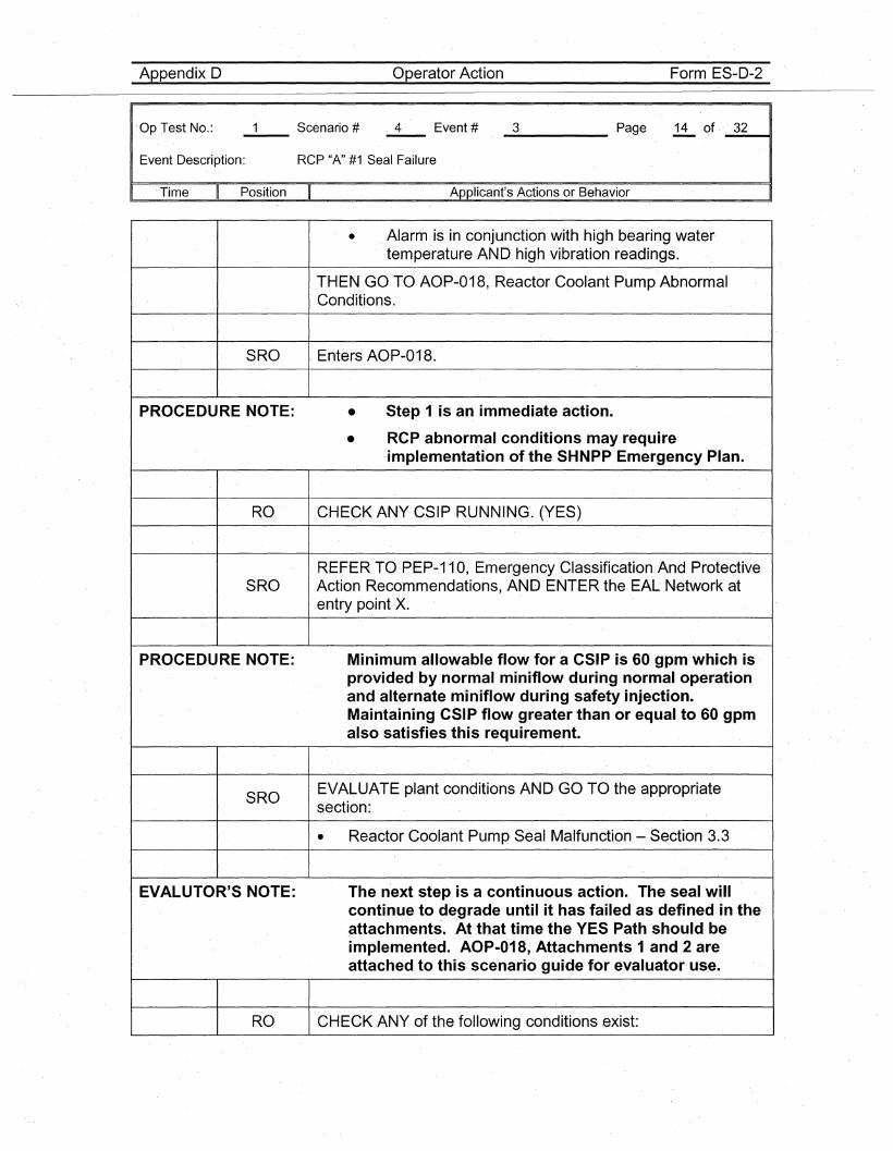
Appendix D Operator Action Form ES-D-2
'Op Test No.:
Event Description: Rep "A" #1 Seal Failure
_3_. Page 14 of . _3_2---11
.Time Position Applicant's Actions or Behavior
• Alarm is in conjunction with high bearing watertemperature AND high vibration readings.
THEN GO TO AOP-018, Reactor Coolant Pump AbnormalConditions.
SRO Enters AOP-018.
PROCEDURE NOTE: • Step 1 is an immediate action.
• RCP abnormal conditions may require·implementation of the SHNPP Emergency Plan.
RO CHECK ANY CSIP RUNNING. (YES)
REFER TO PEP-110, Emergency Classification And ProtectiveSRO Action Recommendations, AND ENT,ER the EAL Network at
entry point X.
PROCEDURE NOTE: Minimum allowable flow for a CSIP is 60 gpm which is .provided by normal miniflow during normal operationand alternate miniflow during safety injection.Maintaining CSIP flow greater than or equal to 60 gpmalso satisfies this requirement.
SROEVALUATE plant conditions AND GO TO the appropriatesection:
• Reactor Coolant Pump Seal Malfunction - Section 3.3
EVALUTOR'S NOTE: The next step is a continuous action. The seal willcontinue to·degrade until it has failed as defined in the.attachments. At that time the YES Path should· beimplemented. AOP-018,Attachments 1 and 2 areattached to this scenario guide for evaluator use.
RO CHECK ANY of the following conditions exist:
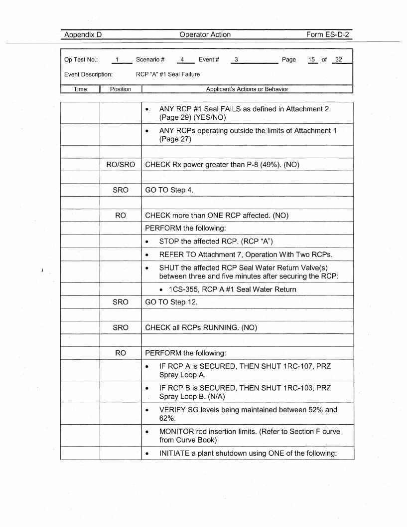
Appendix D Operator Action .Form ES-D-2
Op Test No.:
Event Description: Rep "A" #1 Seal Failure
_3 Page 15 of _3_2~,
Time Position Applicant's Actions or Behavior
./ ANY RCP #1 Seal FAILS as defined in Attachment 2(Page 29) (YES/NO)
• ANY RCPs operating outside the limits of Attachment 1(Page 27)
RO/SRO CHECK Rx power greater than P-8 (49%). (NO)
SRO GO TO Step 4.
RO CHECK more than ONE RCPaffected. (NO)
PERFORM the following:
• STOP the affected RCP. (RCP "A")
• REFER TO Attachment 7, Operation With Two RCPs.
• SHUT the affected RCP Seal Water Return Valve(s)between three and five minutes after securing the RCP:
• 1CS-355, RC'P A #1 Seal Water Return
SRO GO TO Step 12.
SRO CHECK all RCPs RUNNING. (NO)
RO PERFORM the following:
• IF RCP A is SECURED, THEN SHUT 1RC-107, PRZSpray Loop A.
• IF RCP B is SECURED, TH,EN SHUT 1RC-1 03, PRZSpray Loop B. (N/A)
• VERIFY SG levels being maintained between 52% and620/0.
• MONITOR rod insertion limits. (Refer to Section F curvefrom Curve Book)
• INITIATE a plant shutdown using ONE of the following:
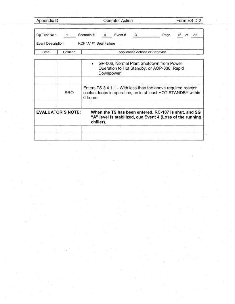
Appendix D Operator·Action Form ES-D-2
Op.Test No.:
Event Description: Rep "A" #1 Seal Failure
_3 Page 16 of· _3_2----11
. Time Position Applicant's Actions or Behavior
• GP-006, Normal Plant Shutdown from PowerOperation to Hot Standby, ·or AOP-038, RapidDownpower.
Enters TS 3.4.1.1 - With ·Iess than the above required reactorSRO coolant loops in operation, be in at least HOT STANDBY within
6 hours.
EVALUATOR'S NOTE: When the TS has been entered, RC-107 is shut, and SG"A" level is stabilized, cue Event 4 (Loss of the running.chiller).
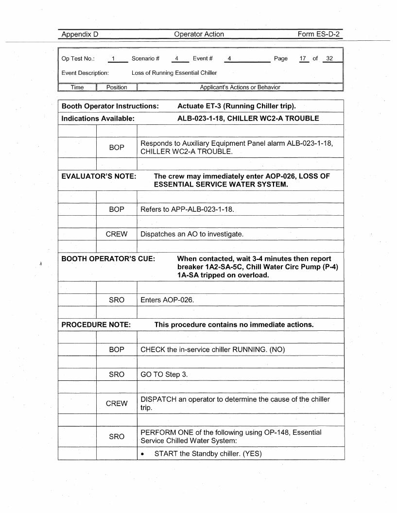
Appendix D Operator Action Form ES-D-2
Op Test No.:
Event Description: Loss of Running Essential Chiller
_4 Page 17 of _3_2---11
Time Position II Applicant's Actions or Behavior
Booth Operator Instructions: Actuate ET-3 (Running Chiller trip).
Indications Available: ALB-023-1-18, CHILLER WC2-A TROUBLE
BOPResponds to Auxiliary Equipment Panel alarm ALB-023-1-18,CHILLER WC2-A TRO,UBLE.
E'VALUATOR'S NOTE: The crew may immediately enter AOP-026, LOSS OFESSENTIAL SERVICE WATER SYSTEM.
BOP Refers to APP-ALB-023-1-18.
CREW Dispatches an AO to investigate.
BOOTH OPERATOR'S CUE: When contacted, wait 3-4 minutes then're,portbreaker 1A2-SA-5C, Chill Water Circ Pump (P-4)1A-SA tripped on overload.
SRO Enters AOP-026.
PROCEDURE NOTE: This procedure contains no immediate actions.
BOP CHECK the in-service chiller RUNNING. (NO)
SRO GO TO Step 3.
CREWDISPATCH an operator to determine the cause of the chillertrip.
SROPERFORM ONE of the following using OP~148, EssentialService Chilled Water System:
• START the Standby chiller. (YES)
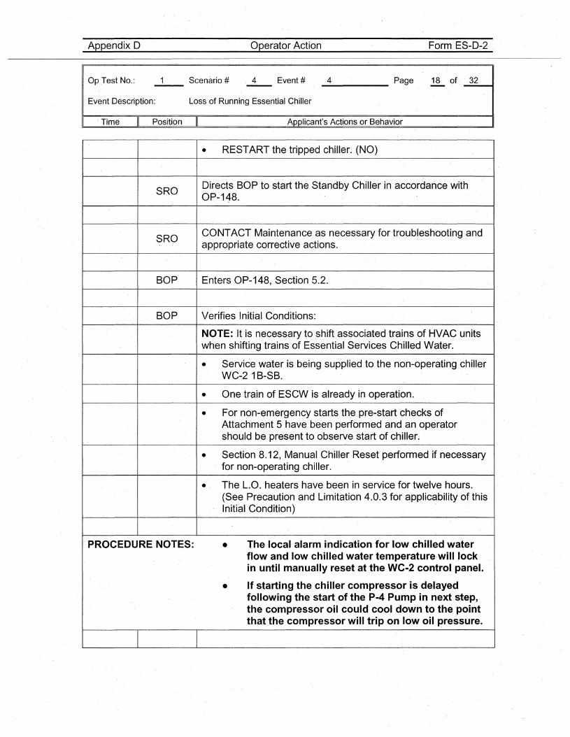
Appendix D Operator Action Form ES-D-2
Op .Test No.:
Event Description: Loss of Running Essential Chiller
_4_. Page 18 of· _3_211
. Time Position Applicant's Actions or Behavior
• RESTART the tripped chiller. (NO)
SRODirects BOP to start the Standby Chiller in accordance withOP-148.
SROCaNTACT Maintenance as necessary for troubleshooting andappropriate corrective actions.
BOP Enters OP-148, Section 5.2.
BOP Verifies Initial Conditions:
NOTE: It is necessary to shiftassociated trains of HVAC unitswhen shifting trains of Essential Services Chilled Water.
• Service water is being supplied to the non-operating chillerW.C-2 1B-SB.
• One train of ESCW is already in operation.
• For non-emergency starts the pre-start checks ofAttachment 5 have been performed and an operatorshould be present to observe start of ch·iller.
• Section 8.12, Manual Chiller Reset p'erformed if necessaryfor non-operating chiller.
• The L.a. heaters have been in service for twelve hours.(See Precaution and Limitation 4.0~3 for applicability of thisInitial Condition)
PROCEDURE NOTES: • The local alarm indication for low chilled waterflow and low chilled water temperature·wililockin until manually reset at the WC-2 control panet
• If starting the chiller compressor is delayedfollowing the start of the P-4 Pump in next step,the compressor oil could cool down to the pointthat the compressor will trip on low oil pressure~
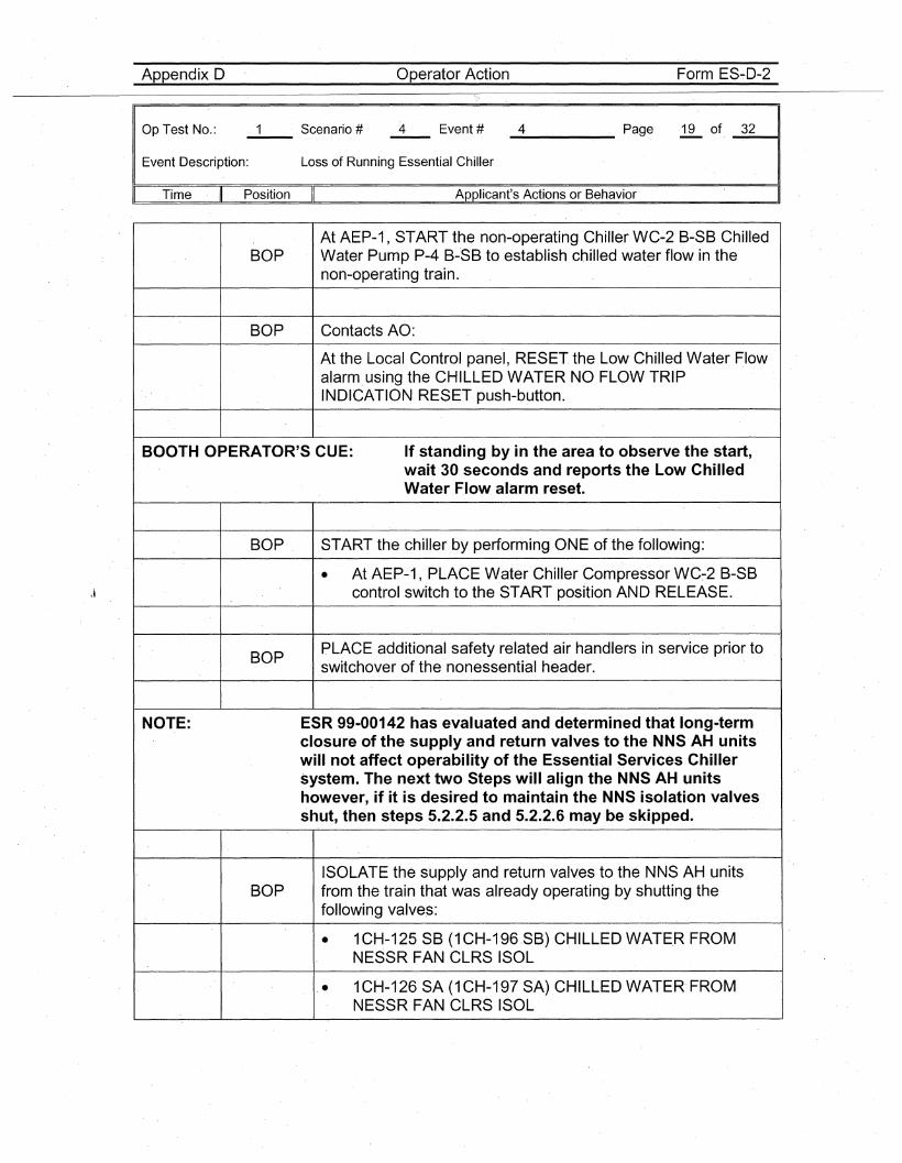
Appendix D Operator Action Form ES-D-2
Op Test No.:
Event Description: Loss of Running Essential Chiller
_4 Page 19 of _3_211
Time Position Applicant's Actions or Behavior
At AEP-1, START the non-operating Chiller WC-2 B-SB ChilledBOP Water Pump P-4 B-SB to establish chilled water flow in the
non-operating train.
BOP Contacts AO:
At the Local Control panel, RESET the Low Chilled Water Flowalarm,using the CHILLED WATER NO FLOW TRIPINDICATION RESET push-button.
BOOTH OPERATOR'S CUE: If standing by in the area to observe the start,wait 30 seconds and reports the Low ChilledWater Flow alarm re·set.
BOP START the chiller by performing ONE of the following:
• At AEP-1, PLACE Water Chiller Compressor WC~2 B-SBcontrol switch to the START position AND RELEASE.
BOPPLACE additional safety related.air handlers in service prior toswitchover of the nonessential header.
NOTE: ESR 99-00142 has evaluated and determined that I'ong-termclosure of the supply and return valves to the NNS AH unitswill not affect operability of the Essential Services Chillersystem. The next two Steps will align the NNS AH unitshowever, if it is desired to maintain theNNS isolation valvesshut, then steps 5.2.2.5 and 5.2.2.6 may be skipped.
ISOLATE the supply and return valves to the NNS AH unitsBOP from the train that was already operating by shutting the
following valves:
• 1CH-125 SB (1CH-196.SB) CHILLED WATER FROMNESSR FAN CLRS ISOL
• 1CH-126 SA (1CH-197 SA) CHILLED WATER' FROMNESSR FAN CLRS ISOL
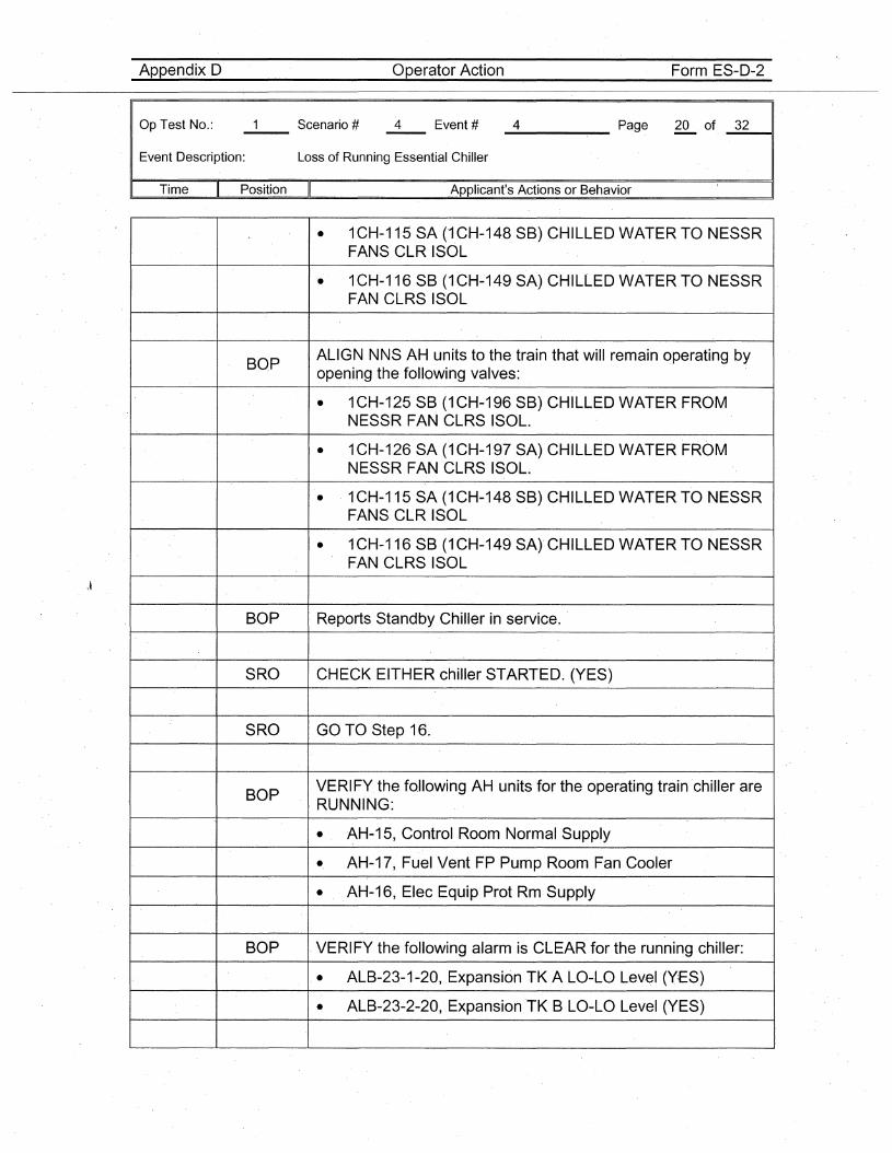
Appendix D Operator Action Form ES-D-2
Op Test No.:
Event Description: Loss of Running Essential Chiller
_4 Page 20 of _3_2----11
Time " Position II Applicant's Actions or Behavior
• 1CH-115 SA (1CH-148 SB) CHILLED WATER TO NESSRFANS CLR I'SOL
• 1CH-116 SB (1CH~149 SA) CHILLED WATER TO NESSRFAN CLRS ISOL
BOPALIGN NNS AH units to the train that will remain operating byopening the following valves:
• 1CH-125 SB (1CH-196 SB) CHI'LLED WATER FROMNESSR FAN CLRS ISOL.
• 1CH-126 SA (1CH-197 SA) CHILLED WATER FROMNESSR FAN CLRS ISOL~
• 1CH-115 SA (1 CH-148 SB) CHILLED WATER TO 'NESSRFANS CLR ISOL
• 1CH-116 SB (1CH-149 SA) CHILLED WATER TO NESSRFAN CLRS ISOL
BOP Reports Standby Chiller in service.
S'RO CHECK EITHER chiller STARTED. (YES)
SRO GO TO Step 16.
BOPVERIFY, the foJlowing AH units for the operating train chiller areRUNNING:
• ~H-15, Control Room Normal Supply
• AH-17, Fuel Vent FP Pump Room Fan Cooler
• , ,AH-16, Elec Equip Prot Rm Supply
BOP ,VERIFY the following alarm is CLEAR for the running chiller:
• ALB-23-1-20, Expansion TK A LO-LO Lev,el (YES)
• ALB-23-2-2'O, ,ExpansionTK B LO-LO Level (YES)
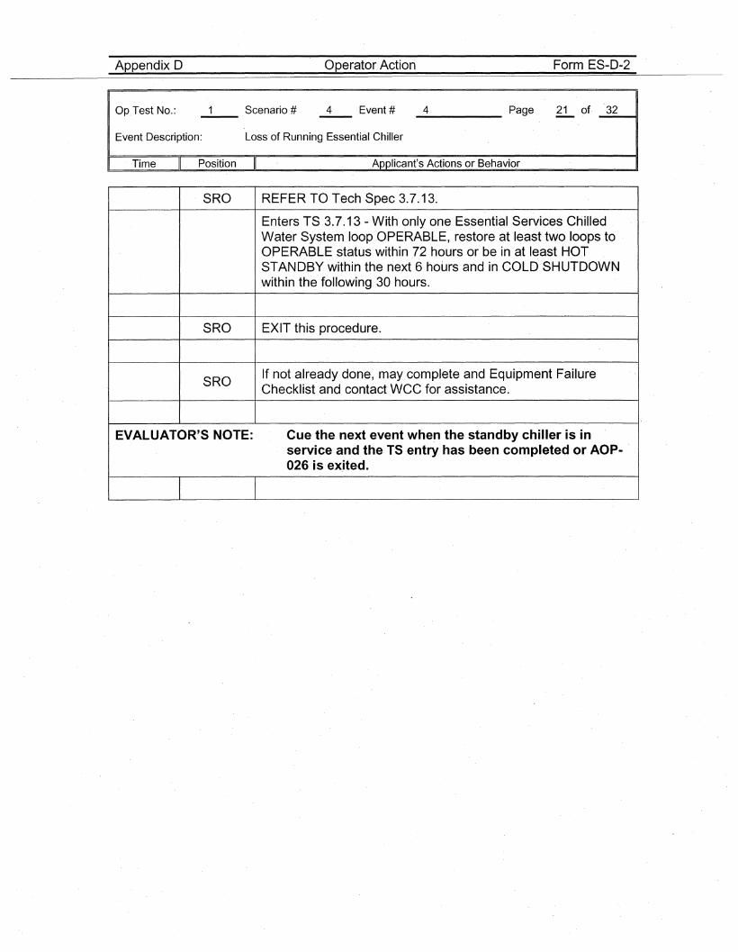
Appendix D Operator Action Form ES-D-2
Op.Test No.:
Event Description: Loss of Running Essential Chiller
_4 Page 21 of. _3_2---11
Time Position II Applicant's Actions or Behavior
SRO REFER TO Tech Spec 3.7.13.
Enters TS 3.7.13 - With only one Essential Services ChilledWater System loop OPERABLE, restore at least two I'oops to .OPERABLE status within 72 hours or be in at least HOTSTANDBY within the next 6 hours and in COLD SHUTDOWNwithin the following 30 hours.
SRO EXIT this procedure.
SROIf not already done, may complete and Equipment FailureChecklist and contact WCC for assistance.
EVALUATOR'S NOTE: Cue the next event when the standby chiller is inservice and the TS entry has been completed or AOP-026 is exited.
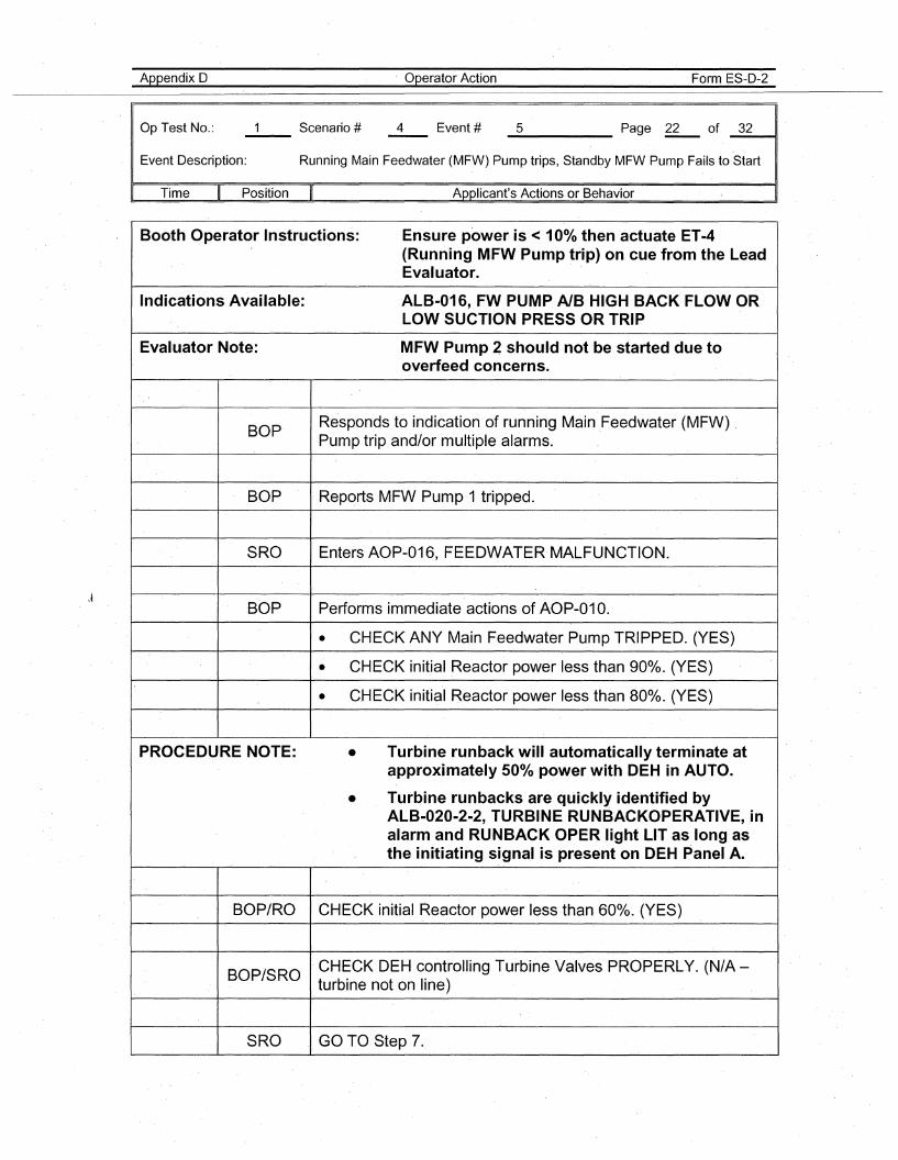
Appendix D
Op Test No.:
. Operator Action Form ES-D-2
_5 Page ~ of _3_2---11
Event Description: Running Main Feedwater (MFW) Pump trips, Standby MFW Pump Fails to Start
Time Position Applicant's Actions or Behavior
Booth Operator Instructions: Ensure power is < 10% then actuate ET-4(Running MFW Pump trip) on cue from the LeadEvaluator.
Indications Available: ALB-016, FW PUMP AlB HIGH BACK FLOW ORLOW SUCTION PRESS OR TRIP
Evaluator Note: MFW Pump 2 should not be started due tooverfeed concerns.
BOP'Responds to indication of running Main Feedwater (MFW)Pump trip and/or multiple alarms.
BOP Reports MFW Pump 1 tripped.
SRO Enters AOP-016, FEEDWATER·MALFUNCTION.
BOP Performs immediate actions of AOP-01 O.
• CHECK' ANY Main Feedwater Pump TRIPPED. (YES)
• CHECK initial Reactor power less than 900/0. (YES)
• CHECK initial Reactor power less than 800/0. (YES)
PROCEDURE NOTE: • Turbine runback will automatically terminate atapproximately 500/0 power with DEH in AUTO.
• Turbine runbacks are quickly identified byALB-020-2~2,TURBINE RUNBACKOPERATIVE, .inalarm and RUNBACK OPER light LIT as long' asthe initiating signal is present on DEH Panel A.
BOP/RO CHECK initial Reactor power less than 600/0. (YES)
BOP/SRO.CHECK DEH controlling Turbine Valves PROPERLY. (N/A-turbine not on line)
SRO GO TO Step 7.
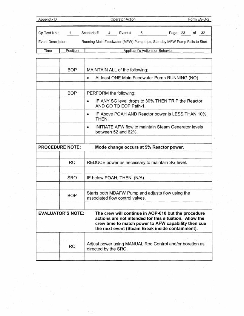
AppendixD
Op Test No.:
Operator Action Form ES-D-2
_5 Page ~ of. _3_211
Event Description: Running Main Feedwater (MFW) Pump trips, Standby MFW Pump Fafls to Start
. Time Position Applicant's Actions or Behavior
BOP MAINTAIN ALL of the following:
• At leastONE Main Feedwater Pump RUNNING (NO)
BOP PERFORM the following:
• IF ANY SG level drops to 300/0 THENTRIPthe ReactorAND GO TO EOP Path-1.
• IF Above POAH AND Reactor power is LESS THAN 100/0,THEN:
• INITIATE AFW flow to·maintainSteam Generator levelsbetween 52 and 62%.
PROCEDURE NOTE: Mode. change occurs at' 5% Reactor power.
RO REDUCE power as necessary to maintain SG level.
SRO IF below POAH, THEN: (N/A)
BOPStarts both MDAFW Pump and adjusts flow using theassociated flow control valves.
EVALUATOR'S NOTE: The crew will continue in AOP-010 but the procedureactions are not intended for this situation. Allow thecrew time to match power to AFW capability then cuethe next event (Steam Break inside containment).
ROAdjust power using MANUAL Rod Control and/or boration asdirected by the SRO.
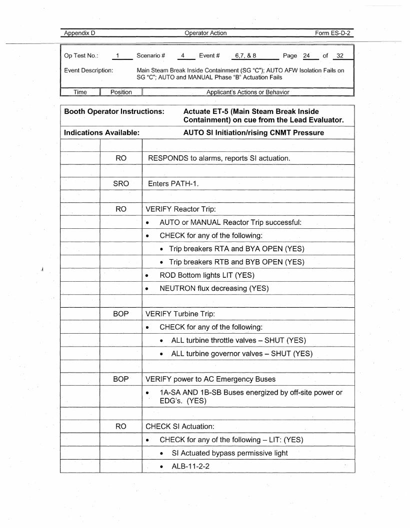
Appendix 0
Op Test No.:
Operator Action Form ES-D-2
_6....,7.-.,_&_8 Page ~ of _3_2---11
Event Description: Main Steam Break Inside Containment (SG "C"); AUTO AFW Isolation Fails onSG "e"; AUTO and MANUAL Phase "B" Actuation Fails
Time Position Applicant's Actions or Behavior
\~
Booth Operator Instructions: Actuate ET-5 (Main Steam Break InsideContainment) on cue from the Lead Evaluator.
Indications Available: AUTO 51 Initiation/rising CNMT Pressure
RO RESPONDS to alarms, reports'SI actuation.
SRO Enters PATH-1.
RO VERIFY Reactor Trip:
• AUTO or MANUAL Reactor Trip successful:
• CHECK for any of the following:
• Trip breakers RTA and BYA OPEN (YES)
• Trip breakers RTB and BYB OPEN (YES)
• ROD Bottom lights LIT (YES)
• NEUTRON flux decreasing (YES)
BOP VERIFY Turbine .Trip:
• CHECK for any of the following:
• ALL turbine throttle valves - SHUT (YES)
• ALL turbine governor valves - SHUT (YES)
BOP VERIFY power to AC Emergency Buses
• 1A-SA AND 1B-SB Buses energized by off-site power orEDG's. (YES)
RO CHECK SI Actuation:
• CHECK for any of the following - LIT: (YES)
• SIActuated bypass permissive light
• ALB-11-2-2
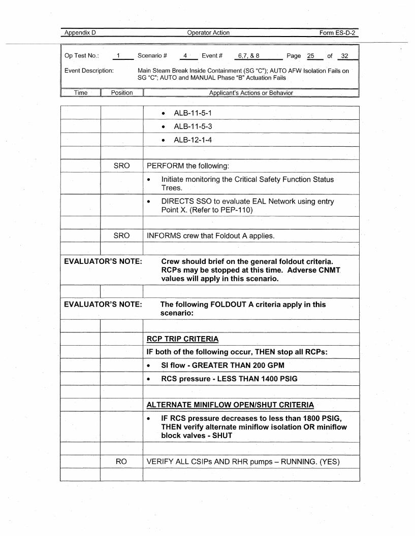
Appendix 0
Op Test No.:
Operator Action Form ES-D-2
_6....:.,,7.....,_&_8 Page ~ of, _3_2__11
Event Description: Main Steam Break In$ide Containment (SG "C"); AUTO AFW Isolation' Fails onSG "C"; AUTO and MANUAL Phase "B" Actuation Fails
I, Time' Position II Applicant's Actions or Behavior
• ALB-11-5-1
• ALB-11-5-3
• ALB-12-1-4
SRO PERFORM the following:
• Initiate monitoring the Critical Safety Function StatusTrees.
• DIRECTS SSG to evaluate EAL Network using entryPoint X. (Refer to PEP-11 0)
SRO INFORMS crew that Foldout A applies.
EVALUATOR'S NOTE: Crew 'should brief on the general fold'out criteria.RCPs may be stopped at this time. Adverse CNMTvalues will apply in this scenario.
EVALUATOR'S NOTE: The following FO,LDOUT A 'criteria apply in thisscenario:
RC,P TRIP CRITERIA
IF, both of the following occur, THEN stop all RCPs:
• SI flow· GREATER THAN 200 GPM
• RCS pressure· LESS THAN-1400 PSIG
ALTERNATE MINIFLOW OPEN/SHUT CRITERIA
• IF RCS pressure decreases to less than 1800 PSIG,THEN verify alternate miniflow isolation OR miniflowblock valves • SHUT
RO VERIF'Y ALL CSIPs AND RHR pumps - RUNNING. (YES)
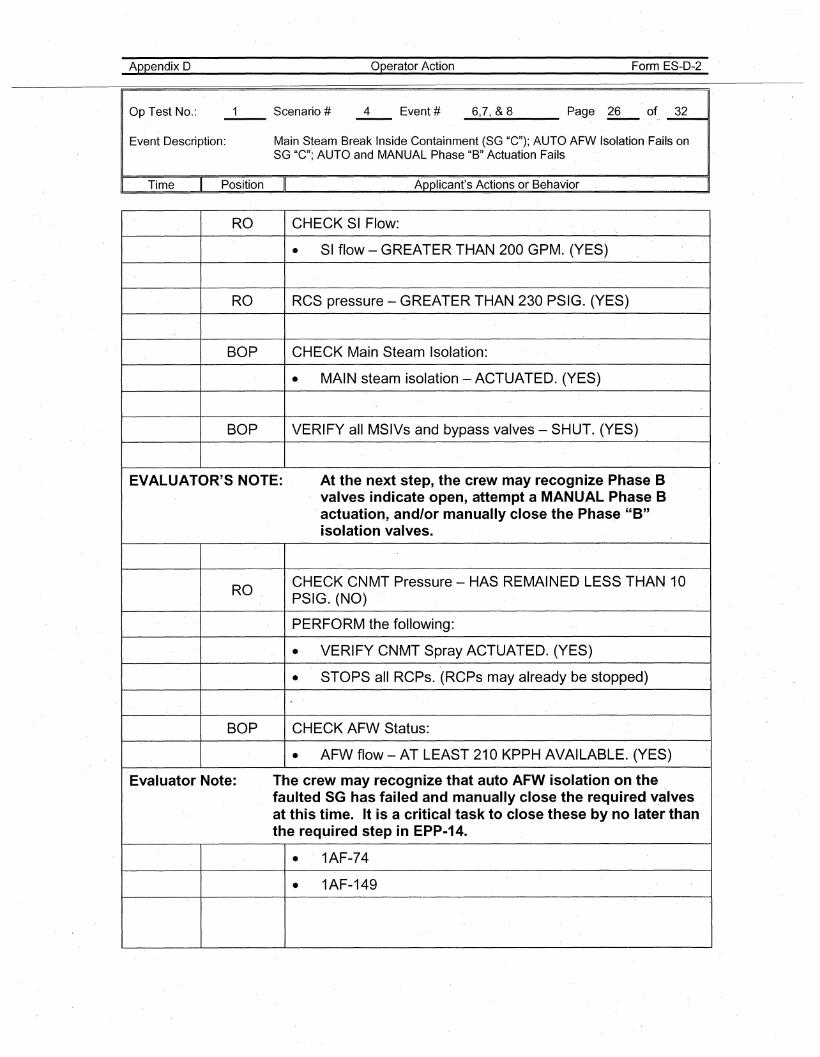
Appendix 0
Op Test No.:
Operator Action Form ES-D-2
_6..-,7..-,_&_8 Page '~o~, _3_2__11
Event Description: Main Steam Break Inside Containment (SG "C"); AUTO AFW Isolation' Fails onSG "C"'; AUTO and MANUAL Phase "B" Actuation Fails
" Time Position II Applicant's Actions or Behavior
RO CHECK SI Flow:
• SI flow - GREATER THAN 200 GPM. (YES)
RO RCS pressure - GREATER THAN 230 PSIG. (YES)
BOP CHECK Main Steam Isolation:
• MAIN steam isolation - ACTUATED. (YES)
BOP VERIFY all MSIVs and bypass valves - SHUT. (YES)
EVALUATOR'S N,OTE: At the next step, the crew may recognize Phase Bvalves indicate open, 'attempt a MANU'AL Phase Bactuation, and/or manually close the Phase "B"isolation valves.
ROCHECK CNMT Pressure - HAS REMAINED LESS THAN 10PSIG. (NO)
PERFORM the following:
• VERIFY CNMT Spray ACTUATED. (YES)
• STOPS all Reps. (RCPs may already be stopped)
BOP CHECK AFW Status:
• AFW flow - AT LEAST 210 KPPH AVAILABLE. (Y'ES)
Evaluator Note: The crew may recognize that auto AFW isolation on the ,faulted SG has failed and manually close the required v,alvesat this time. It is a critical task to cl,ose these by no later thanthe required step i'n EPP-14.
• 1AF-74
• 1AF-149
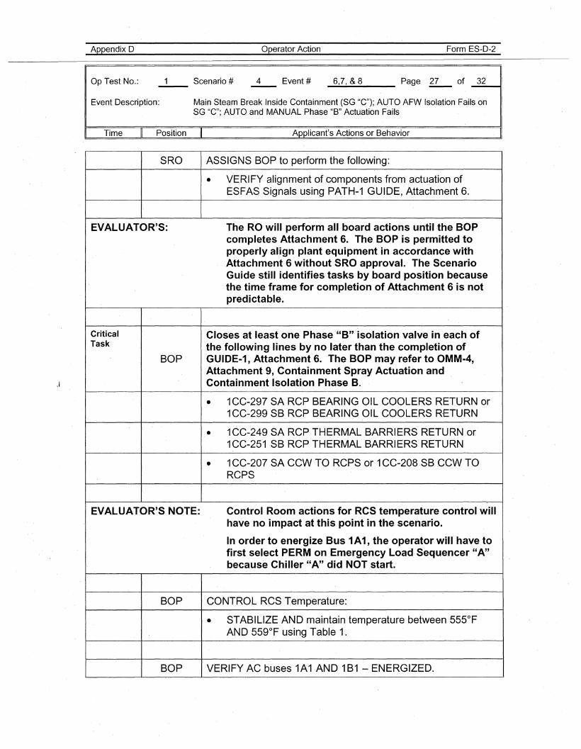
Appendix 0'
Op Test No.:
Operator Action Form ES-D-2
_6.....,7.....,_&_8 Page ,gz....- of _3_2----11
Event Description: Main Steam Break Inside Containment (SG "C"); AUTO AFW Isolation Fails onSG "C"; AUTO and MANUAL Phase "B" Actuation Fails
Time Position Applicant's Actions or Behavior
SRO ASSIGNS BOP to perform the following:
• VERIFY alignment of components from actuation ofESFAS Signals using PATH-1 GUIDE, Attachment 6.
EVALUATOR'S: The RO will perform all board actions until the BOPcompletes Attachment 6. The BOP .is permitted toproperly align plant equipment in accordance withAttachment 6 without SRO approval. The ScenarioGuide still identifies tasks by board position becausethe time frame for completion of Attachment 6 is notpredictable.
Critical Closes at least one Phase "B" isolation valve in each ofTask the following lines by no later than the completion of
BOP GUIDE·1, Attachment 6. The BOP may refer to OMM-4,Attachment 9, Containment Spray Actuation andContainment Isolation Phase B.
• 1CC-297 SA RCP BEARING OIL COOLERS RETURN or1CC-299 SB RCP BEARING OIL COOLERS RETURN
• 1CC-249 SA RCP THERMAL BARRIERS RETURN or1CC-251 SB RCP THERMAL BARRIERS RETURN
• 1CC-207 SA CCW TO RCPS or 1CC-208 ,SB CCW TORCPS
EVALUATOR'S NOTE: Control Room actions for RCS temperature control willhave no impact at this point in the scenario.
In order to energize Bus 1A1, the operator will have tofirst select PERM on Emergency Load Sequencer "A"because Chiller "A" did NOT start.
BOP CONTROL RCS Temperature:
• STABILIZE AND maintain temperature between 555°FAND 559°F using Table 1.
BOP VERIFY AC buses 1A1 AND 1B1 - ENERGIZED.
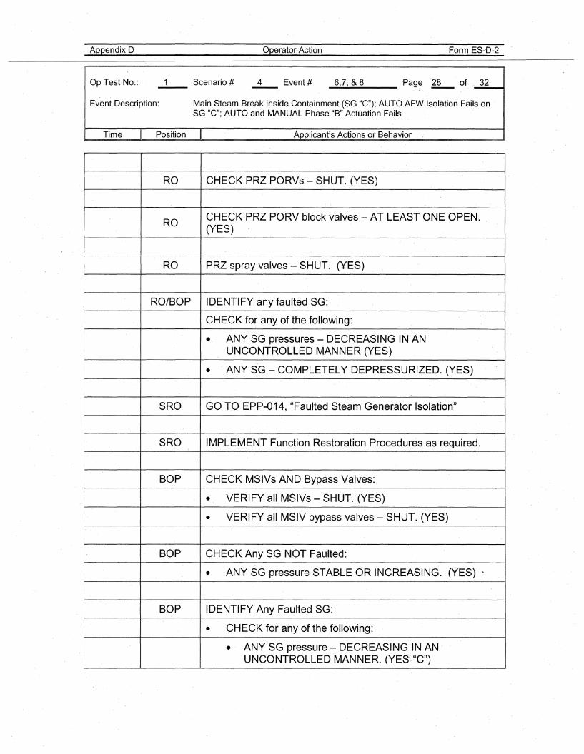
Appendix 0
Op Test No.:
Operator Action Form ES-D-2
_6--.,7.....,_&_8 Page .~ of _3_2----11
Event Description: Main Steam Break Inside Containment (SG "C"); AUTO AFW Isolation Fails onSG "C"; AUTO and MANUAL Phase "B" Actuation Fails
Time II Position II Applicant's Actions or Behavior
RO CHECK PRZ PORVs - SHUT. (YES)
ROCHECK PRZ PORV block valves - AT LEAST ONE OPEN.(YES)
RO PRZ spray valves - SHUT. (YES)
RO/BOP IDENTIFY any faulted SG:
CHECK for any of the following:
• ANY SG pressures - DECREASING IN ANUNCONTROLLED MANNER (YES)
• ANY SG ~ COMPLETELY DEPRESSURIZED. (YES)
SRO GO TO· EPP-014, "Faulted Steam Generator Isolation"
SRO IMPLEMENT Function Restoration Procedures as required.
BOP CHECK MSIVs AND Bypass Valves:
• VERIFY all MSIVs - SHUT·. (YES)
• VERIFY all MSIV bypass valves - SHUT. (YES)
BOP CHECK Any SG NOT Faulted:
• ANY SG pressure STABLE OR INCREASING. (YES) ~
BOP IDENTIFY Any Faulted SG:
• CHECK for any of the following:
• ANY SG pressure- DECR'EASING IN AN .UNCONTROLLED MANNER. (YES'-"C")
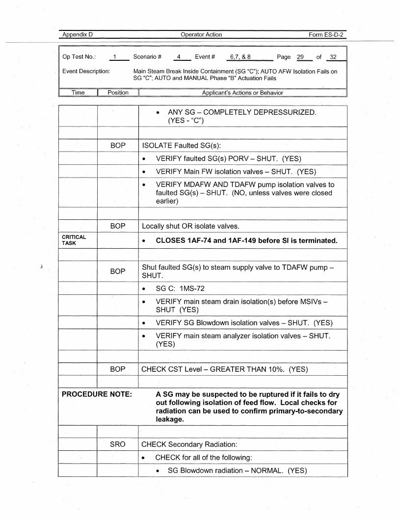
Appendix 0'
Op Test No.:
operator Action Form ES-O-2
_6...,7.....,_&_8 Page ~ of _3_2~,
Event Oescription: Main Steam Break Inside Containment (SG "C"); AUTO AFW Isolation Fails onSG "C"; AUTO and MANUAL Phase "B" Actuation Fails
Time Position Applicant's Actions or Behavior
• ANY SG - COMPLETELY DEPRESSURIZED.(YES - "C")
BOP ISOLATE Faulted SG(s):
• VERIFY faulted SG(s) PORV - SHUT. (YES)
• VERIFY Main FW isolation valves- SHUT. (YES)
• VERIFY MDAFW AND TDAFW pump isolation valves tofaulted SG(s) - SHUT. (NO, unless valves were closedearlier)
BOP Locally shut OR isolate valves.
CRITICAL CLOSES 1AF-74 and 1AF-149 before 51 is terminated.TASK •
BOPShut faulted SG(s) to steam supply valve to TDAFW pump-SHUT.
• SG C: 1MS-72
• VERIFY main steam drain isolation(s) before MSIVs-SHUT (YES)
• VERIFY SG Blowdown isolation valves - SHUT. (YES)
• VERIFY main steam analyzer isolation valves - SHUT.(YES)
BOP ,CHECK CST Level- GREATER THAN 10%. (YES)
PROCEDURE NOTE: A SG may be suspected to be ruptured if it fails to dryout following isolation of feed flow. Local checks forrad.iation can be used to confirm primary-to-secondaryleakage.
SRO ,CHECK Secondary Radiation:
• CHECK for all of the following:
• SG Blowdown radiation - NORMAL. (YES)
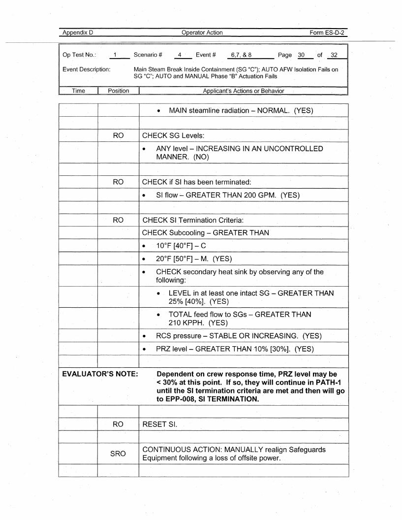
Appendix D
Op Test No.:
Operator Action Form ES-D-2
_6..-,7..-,_&_8 Page ~ of. _3_211
Event Description: Main Steam Break Inside Containment (SG "C"); AUTO AFW Isolation 'Fails onSG "C"; AUTO and MANUAL Phase "B" Actuation Fails
Time Position II Applicant's Actions or Behavior
• MAIN steamline radiation - NORMAL. (YES)
RO CHECK SG Levels:
• ANY level- INCREASING IN AN UNCONTROLLEDMANNER. (NO)
RO CHECK if SI has been terminated:
• SI flow ~ GREATER THAN 200 GPM. (YES)
RO CHECK SI Termination Criteria:
CHECK Subcooling - GREATER THAN
• 10°F [40°F] -C
• 20°F [50°F] - M. (YES)
• CHECK secondary heat sink by observing any of thefollowing:
• LEVEL in at least one intact SG - GREATER THAN250/0 [40%]. (YES)
• TOTAL feed flow to SGs - GREATER THAN210 KPPH. (YES)
• RCS pressure - STABLE. OR·INCREASING. (YES)
• PRZ level- GREATER THAN ·10%.[30%]. (YES)
EVALUATOR'S NOTE: Dependent on crew response time, PRZ level may be< 300/0 at th'is point. If so, they will continue in PATH-1until the 51 termination criteria are met and then will goto EPP~008, 51 TERMINATION..
RO RESET SI.
SROCONTINUOUS ACTION: MANUALLY realign SafeguardsEquipment following. a loss of offsite power.
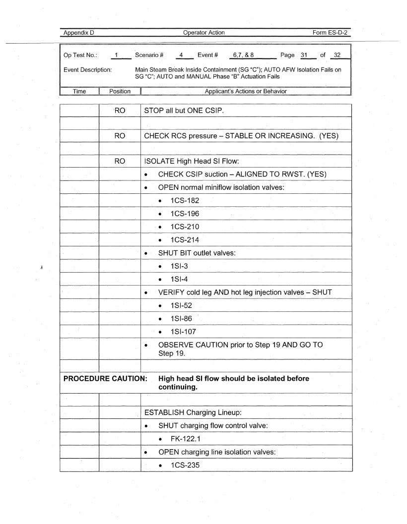
Appendix D
Op Test No.:
Operator Action Form ES-D-2
_6.....,7.....,_&_8 Page l:!...- of _3_2---11
Event Description: Main Steam Break Inside Containment (SG "C"); AUTO AFW Isolation Fails onSG "C"; AUTO and MANUAL Phase "B" Actuation Fails
Time Position Applicant's Actions or Behavior
'RO STOP all but ONE CSIP.
RO CHECK RCS pressure - STABLE OR INCREASING. (YES)
RO ISOLATE High Head SI Flow:
• CHECK CSIP suction - ALIGNED TO RWST. (YES)
• OPEN normal miniflow isolation valves:
• 1CS-182
• 1CS-196
'. 1CS-210
• 1CS-214
·'
SHUT BIT outlet valves:
• 1SI-3
• 1SI-4
• VERIFY cold'ieg AND hot leg 'injection valves- SHUT
• 1SI-52
• 181-86
• 1SI-107
• OBSERVE CAUTION prior to Step 19 AND GO TOStep 1'9.
PROCEDURE CAUTION: High head 51 flow should be isolated beforecontinu,ing.
ESTABLISH C,harging Lineup:
• SHUT charging flow control valve:
• FK-122.1
• OPEN charging line isolation valves:
• 1CS-235
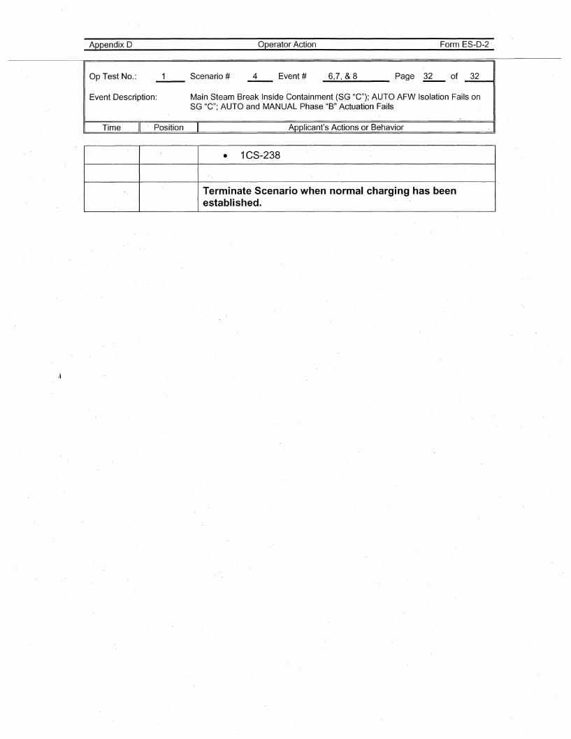
Appendix O·
Op Test No.: 4
Operator Action
Event # 6,7, & 8
Form ES-O-2
Page ~ of _3_2_-41
Event Oescription: Main Steam Break Inside Containment (SG "C"); AUTO AFWlsolation Fails onSG "C"; AUTO and MANUAL Phase "B" Actuation Fails
Time Position Applicant's Actions or Behavior . I
\~
• 1CS-238
Terminate Scenario when normal charging has beenestablished.