Embed Size (px)
Citation preview

HAROKOPIO UNIVERSITY OF ATHENS - HUA
Department of Informatics and Telematics
Coherent Optical Wireless Systems for High
Speed Local Area Networks with Increased Resilience
Katerina Margariti, HUAThomas Kamalakis, HUA

HAROKOPIO UNIVERSITY OF ATHENS - HUA
Department of Informatics and Telematics
Outline• WLANs - Candidate Technologies
• Optical Wireless Technology Basic Features
• System Architecture
• System Setup & Link Types
• System Performance
• Multipath Induced Distortion
• Future Considerations

HAROKOPIO UNIVERSITY OF ATHENS - HUA
Department of Informatics and Telematics
High-Speed WLAN Candidate Technologies
or POF
or POF
OWUWBWi-Fi60GHz
UWB provides data rates that are limited up to few hundred Mbps and suffers from strong interference
802.11n is limited to 600Mb/s, even when a MIMO configuration is used
60GHz systems promise license-free continuous bandwidth with a spectral space of 5-7GHz. High data rates on the order of a few Gbps
HAROKOPIO UNIVERSITY OF ATHENS - HUA
Department of Informatics and Telematics
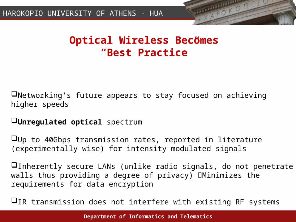
Optical Wireless Becomes “Best Practice”
Networking's future appears to stay focused on achieving higher speeds
Unregulated optical spectrum
Up to 40Gbps transmission rates, reported in literature (experimentally wise) for intensity modulated signals
Inherently secure LANs (unlike radio signals, do not penetrate walls thus providing a degree of privacy) Minimizes the requirements for data encryption
IR transmission does not interfere with existing RF systems

HAROKOPIO UNIVERSITY OF ATHENS - HUA
Department of Informatics and Telematics
System ArchitectureCoherent DetectionAllows a complete representation of the optical field into the electrical domain
It provides intensity, phase, and polarization information from the incoming signal
( ) 2 ( )s LOI t Rreal E E

HAROKOPIO UNIVERSITY OF ATHENS - HUA
Department of Informatics and Telematics
Tx/Rx Placement - Link TypesPosition & Orientation / Configuration A B C D
Transmitterx(m) 10 10 --- 10y(m) 10 10 --- 10z(m) 3 3 0.8 0.8elevation -900 -900 +900 +900
Receiverx(m) --- --- --- ---
y(m) --- --- --- ---
z(m) 0.3 0.3 0.3 0.3elevation +900 +900 +900 +900

HAROKOPIO UNIVERSITY OF ATHENS - HUA
Department of Informatics and Telematics
Channel DC Gain Spatial Distribution
directed LOS m=2 , FOVR =600
non-directed LOS / diffuser, FOVR = 600
directed non-LOSρ=0.8, FOVR=600
diffuse ρ=0.8 FOVR=600
Channel DC gain (×10-6) for different optical link configurations

HAROKOPIO UNIVERSITY OF ATHENS - HUA
Department of Informatics and Telematics
Modeling Laser Phase NoiseLaser phase noise undergoes a Brownian-motion-type process1
1G. Einarsson et. al., “Error Probability Evaluation of Optical Systems Disturbed by Phase Noise and Additive Noise”, IEEE Journal of Lightwave Technology, vol. 13, 1995.
10
( ) 2 ( ) 2t N
ii
t d
2 .2
v
Laser phase noise is modeled by summing up a number of discrete "jumps" determined by the random variables μi.
It has been shown that:

HAROKOPIO UNIVERSITY OF ATHENS - HUA
Department of Informatics and Telematics
Receiver Sensitivity
•Laser phase noise causes the system performance to be degraded
•Evaluating its effect by ignoring all other noise sources
•The phase noise BER floor over a range of laser linewidth to system bit rate values calculated by our numerical model and out of 107 transmitted bits
•The results are in good agreement with those obtained in (Kaiser et al. 1995) for the standard binary DPSK receiver
Kaiser, C. P., Smith, P. J. and Shafi, M.: An Improved Optical Heterodyne DPSK Receiver to Combat Laser Phase Noise. IEEE Journal of Lightwave Technology 13. 525 – 533 (1995)
Acceptable BER performance of 10-3 is obtained for laser linewidths up to 40 MHz, that are certainly within the range of commercially available lasers.
BER floor as a function of the laser linewidth to system bit rate

HAROKOPIO UNIVERSITY OF ATHENS - HUA
Department of Informatics and Telematics
Receiver Sensitivity
Laser linewidths up to 40MHz can be used for a BER value below 10 3 ‑ at -50dBm received power
The same BER performance is obtained at 60dBm and laser ‑linewidth of 20MHz
An increase in the received power at 50dBm will allow ‑almost optimal performance for the same value of laser linewidth
Low receiver sensitivities can be obtained at 1Gbps data rates significantly relaxing link budget limitations…
BER as a function of the received power for different laser linewidth values

HAROKOPIO UNIVERSITY OF ATHENS - HUA
Department of Informatics and Telematics
Transmitted Power Requirements
The results involve 1Gbps data transmission with laser linewidth = 20MHz and FOVR = 600
Horizontal distance between the transmitter (or the reflection point for the hybrid configuration) and the receiver = 1m
As expected, the diffuse topology indicates the worst performance.For BER = 10-3, 5dB power penalty is observed between the hybrid and the diffuse arrangements. At higher levels of emitted power the different arrangements exhibit a quite similar BER performance.
BER as a function of the transmission power

HAROKOPIO UNIVERSITY OF ATHENS - HUA
Department of Informatics and Telematics
Multipath-induced DistortionModeling
The received optical signal envelope may be expressed:
'(t)
2
(0) k i
Njj j
t ii
S H Pe Pe
(t)(0) ,kj jtS H Pe X jY
2
2
1
2
N
ii
P
H(0): channel DC gain , Pt : transmitted optical power, Pi and φi’ : the optical power and the phase of the interfering components, respectively
where: X~N(0,σ2) and Y~N(0,σ2)
According to the CLT:
And variance given by:

HAROKOPIO UNIVERSITY OF ATHENS - HUA
Department of Informatics and Telematics
Calculating σ2
0 0.1 0.2 0.3 0.4 0.5 0.6 0.7 0.8 0.9 1
x 10-7
0
1
2
3
4
5
6
7
8
9
10
Time (sec)
Sum
Impu
lse
Res
pons
e (s
ec-1
)
Simulation Parameters for Investigating Multipath Fading Effect
PARAMETER ValuesRoom: (length, width, height) = (x,y,z) (7.5m, 5.5m, 3.5m)Source: mode 1
(length, width, height) = (x,y,z) (2m, 4m, 3.3m)
(elevation, azimuth) (-900,00)
Receiver: (Adet, FOVR) (1cm2, 700)(length, width, height) = (x,y,z) (6.6m 2.8m 0.8m)
(elevation, azimuth) (900,00)
Channel impulse response for the examined configuration (no LOS signal component)
Barry, J.R., Kahn, J.M., Krause, W.J., Lee, E.A., Messerschmitt, D.G.: Simulation of multipath impulse response for indoor wireless optical channels. IEEE J. Sel. Areas Commun. 11, 367–379 (1993)
2
2
1 1( )
2 2b
N
ii T
P h

HAROKOPIO UNIVERSITY OF ATHENS - HUA
Department of Informatics and Telematics
Performance Degradation due to Fading
-30 -25 -20 -15 -10 -5 0 5 1010
-4
10-3
10-2
10-1
100
Transmitted power (dBm)
Bit
erro
r ra
te
with fadingwithout fading
BER as a function of the transmitted power. The results concern LOS configurations associated or not with multipath fading effects. Laser Linewidth = 20MHz.
Introduces a small power penalty.
In situations where either the diffuse component σ2 is more significant or there is no LOS component measures should be taken in order to mitigate the effect of fading , i.e., OFDM or diversity schemes.

HAROKOPIO UNIVERSITY OF ATHENS - HUA
Department of Informatics and Telematics
Aknowledgement
The research reported is supported by the “ARISTEIA ΙΙ” Action (“COWS” program) of the “Operational programme Education and Life Long Learning” and is co-funded by the European Social Fund (ESF) and the Greek state.

HAROKOPIO UNIVERSITY OF ATHENS - HUA
Department of Informatics and Telematics
The “COWS” Project
S/PSubcarrier
Symbol Mapper
IDFT GI
D/A
D/A
Re
Im
LPF
LPF
MZM
MZM 90o
90o
-
-
A/D LPF
A/D LPF
Re
ImDFT
Data Symbol Decision
P/S
(i) DFT Window Sychronization(ii) Frequency Offset Compensation(iii) Subcarrier recovery
LD
LD
PD
PD
PD
PD
Data in
Data out
Digital OFDM transmitter Analog coherent transmitter
Analog coherent receiverDigital OFDM receiver
(Possibly) D
iffuse Channel
Coherent Optical Frequency Division Multiplexing as a means to mitigate for multipath-induced distortion in diffuse optical wireless links…

HAROKOPIO UNIVERSITY OF ATHENS - HUA
Department of Informatics and Telematics
The “COWS” Project
The project aims:
to provide valuable proof-of-concept on the applicability of coherent optical detection
to investigate the performance of various equalization methods such as OFDM as a means to mitigate multipath dispersion and increase the transmission rate
to undertake a thorough investigation of design parameters at a component and a system level
to investigate MIMO techniques as a means to improve the overall link capacity and coverage
to implement a coherent optical wireless testbed in order to ascertain the applicability of this technology in real world conditions

HAROKOPIO UNIVERSITY OF ATHENS - HUA
Department of Informatics and Telematics
Some Future Considerations…
Modeling the diffuse indoor optical wireless channel
Investigating whether orthogonal frequency modulation (OFDM) will improve the system performance and mitigate ISI, as expected
Investigating the performance of other equalization schemes

HAROKOPIO UNIVERSITY OF ATHENS - HUA
Department of Informatics and Telematics
Thanks for Listening!