Embed Size (px)
Citation preview

The 32nd International Electric Propulsion Conference, Wiesbaden, Germany
September 11 – 15, 2011
1
Harnessing the “Orbital Battery” for Propulsion via Energy-Harvesting Electrodynamic Tethers
IEPC-2011-226
Presented at the 32nd International Electric Propulsion Conference, Wiesbaden • Germany
September 11 – 15, 2011
Sven G. Bilén1 and Jesse K. McTernan2 The Pennsylvania State University, University Park, Pennsylvania 16802, USA
Brian E. Gilchrist3 and Iverson C. Bell4 The University of Michigan, Ann Arbor, Michigan 48109, USA
and
Robert P. Hoyt5 and Nestor R. Voronka6 Tethers Unlimited, Inc., Bothell, Washington 98011, USA
EDTs can be used to generate power on board spacecraft orbiting planetary bodies with a magnetic field and ionosphere, essentially “harvesting” energy from the orbital energy of the spacecraft. Reciprocally, the same system can be used to provide orbit-raising propulsion or to change inclination if current is supplied to the tether. One of the significant promises of EDTs is their ability to generate significant power when other sources are not available, i.e., on the dark side of the Earth, and then thrust when other power is available, essentially recharging an “orbital battery”. In addition, power generation and thrusting consume no expendables, which allows increased mission lifetime. We report on our research effort to develop a better understanding of the power generation capabilities of EDT systems on various scales (small satellites, CubeSats, and femptosats), and to develop system concepts, key elements, and technology roadmaps for their use.
Nomenclature B = Earth’s magnetic field (T) C = capacitance (F) E = electric field (V/m) F = force (N) l = length of tether (m) l = incremental length vector of tether (m) q = charge of an electron (C) R = resistance (Ω) vs = velocity of a spacecraft (m/s) φtether = total tether potential (V)
1 Associate Professor, Engineering Design, Electrical Engineering, and Aerospace Engineering, [email protected]. 2 Graduate Student Research Assistant, Aerospace Engineering, [email protected]. 3 Professor, Electrical Engineering and Space Sciences, [email protected]. 4 Ph.D. Candidate, Electrical Engineering, [email protected]. 5 CEO and Chief Scientist, [email protected]. 6 VP and Chief Technologist, [email protected].
The 32nd International Electric Propulsion Conference, Wiesbaden, Germany
September 11 – 15, 2011
2
I. Introduction ARVESTING of power and energy from the space environment using spacecraft structures offers the promise of reduction in fuel usage as well as extended mission lifetimes and/or enhanced system capability. Apart from
solar cells, limited adoption of other energy harvesting devices on satellites has occurred, such as the conversion and recovery of thermal energy. Other untapped resources available to satellites include gravity, the planetary magnetic field, and the surrounding ionosphere. Electrodynamic tethers (EDTs) represent an innovative scheme to harvest energy in the orbital environment from these resources.
A space tether is a long thin structure that extends from a sub-orbital or orbiting spacecraft such as a rocket, satellite, or space station. Typically, space tethers are many meters in length, but have been as long as ~20 km (19.7 km for the Tethered Satellite System Reflight1) or as short as 1 m. Depending on the application, a tether can be designed to withstand high tensile forces, to be lightweight, of low volume with high surface area, and/or to be highly survivable.
There are three broad categories of space tethers: electrodynamic, momentum exchange, and formation flying.2 The functions of the tether in these configurations are mechanical, electrical, or both. Mechanical tethers (momentum exchange and formation flying) physically connect two masses in orbit but do not necessarily have to be conductive. Electrodynamic tethers are conductive but also generally provide structural support, although strength may come from a material that is not conductive.
EDTs can be composed of any conductive material such as aluminum, which provides suitable conductivity and low density, or copper, which provides higher conductivity per volume but at higher mass. The material can be single stranded, a porous tape, braided similarly to electrical wiring, or braided in an innovated lattice3 to mitigate damage from micrometeoroids and orbital debris (MMOD).
II. Electrodynamic Tether Principles The principles behind the operation of an orbiting EDT system are fairly straightforward. In general, EDTs
possess three key properties:4 1) the wire has an intrinsic electromotive force (emf) generated along it due to the orbital motion of the tether, 2) the wire provides a low-resistance path connecting different regions of the ionosphere, and 3) access to external electron and ion currents is confined to specific locations, such as the endpoint when the conductor is insulated, or collected along a length of bare tether.5
A. Lorentz Force The first principle listed above, emf generation along the tether, results from the Lorentz force on the electrons in
the tether as the system travels through the geomagnetic field. To determine the magnitude of this emf, we start with the Lorentz force equation for charged particles:
BvEF sq , (1)
where q is the charge of an electron, E represents any ambient electric field (small), and vs × B represents the motional electric field as the spacecraft travels at a velocity vs through the Earth’s magnetic field, represented by B. Eq. (1) can be rewritten as
totEF q , (2)
where
BvEE stot , (3)
and represents the total electric field along the tether. In order to get the total emf generated along the tether, we must integrate Etot along the entire length of the tether, l. That is, the total tether potential is
l
s
ldlld
00 tottether )()( lBvlE , (4)
which is negative since electrons in the tether are acted upon by the Lorentz force. Because the ionospheric plasma surrounding the EDT system is generally a good conductor, the ambient electrostatic field E is small and is usually ignored, i.e., E ≈ 0. The tether potential is path independent assuming a conservative resultant electric field and
H

The 32nd International Electric Propulsion Conference, Wiesbaden, Germany
September 11 – 15, 2011
3
steady-state conditions. Thus, φtether can be calculated knowing only the relative locations of the endpoints (separation distance and orientation) and does not depend on the position of the tether between the endpoints.
B. Interactions with the Space Environment The second and third principles are related to
current flow through the tether, which occurs when a connection is made between the tether’s endpoints and the surrounding ionospheric plasma. This can be accomplished via passive or active means. In the passive case, the voltages and currents in the overall system distribute themselves in a self-consistent manner, which can require the endpoints to charge to high levels in order to attract enough current. Active means generally employ an electron generator of some type, such as an electron gun or hollow cathode plasma contactor. With either method, current flows through the tether as shown in Fig. 1 In the passive case, current flows up the tether because the resultant force on the electrons is downwards (towards Earth). After electrons are collected at the subsatellite, they are conducted through the tether to the spacecraft where they are ejected. Current closure occurs in the ionosphere, thus making the overall circuit complete.
If current flows in the tether element, a force is generated as given by
lBIF dlll
)()(0
. (5)
In self-powered mode (energy-harvesting or de-orbit mode), this emf can be used by the tether system to drive the current through the tether and other electrical loads (e.g., resistors, flywheels, batteries), emit electrons at the emitting end, and/or collect electrons at the opposite. In boost mode, on-board power supplies must overcome this motional emf to drive current in the opposite direction, thus creating a force in the opposite direction that boosts the system (see Fig. 1). Thrust levels depend greatly on applied power and typically are less than 1 N.
III. Research Methods Our research team is investigating EDT power harvesting and propulsion on spacecraft sizes from chip-scale
systems (~1 cm2), to the CubeSat platform (10×10×10-cm cubes), to larger spacecraft (>100 kg). For these various spacecraft size ranges, we are evaluating the energy storage capacity of the system using EDTs and the orbital potential as the “power generator”, the feasibility of using an EDT as a propulsion device for the chip-scale spacecraft, suitable material selection for chip-scale spacecraft, and high power generation using long tethers on large spacecraft.
A. Software We employ two software tools, TeMPEST (Tethered Mission Planning and Evaluation Software Tool) and
TetherSim™, to predict the induced tether voltages and collected tether currents of our system of interest. Over the years, TEMPEST has been used to study various tethered systems and support tethered satellite system development and has evolved to include the following features:
• Precision orbital propagator (with perturbations); • Solar and magnetic indices prediction; • Earth magnetic field model; • Neutral atmosphere model (up to 1000-km altitude); • Model of ionospheric densities and temperatures (valid in the altitude range 50 km to 2000 km); • Simple tether libration forced harmonic mode; • Induced electromotive force (emf) tether voltage model; and • Tether current collection model for bare and insulated tethers with various plasma contactors.
Figure 1. EDTs can be used in an “energy harvesting” mode or a “boost” mode.6

The 32nd International Electric Propulsion Conference, Wiesbaden, Germany
September 11 – 15, 2011
4
TeMPEST is being updated to simulate and evaluate the performance of tether systems for power generation with a limited incremental software development effort.
TetherSim is a simulation toolset developed by Tethers Unlimited, Inc. for over a decade to facilitate design and analysis of space and terrestrial systems that involve tethers. TetherSim’s key distinguishing feature when compared to TEMPEST is that it incorporates algorithms for simulating the dynamic behavior of a tether and the bodies connected to it. Consequently, where TEMPEST is more useful for rapid exploration of a wide engineering trade space, TetherSim is more suitable for detailed analysis of system behavior, operations, and effects on the host vehicle. The TetherSim code integrates models for orbital mechanics, tether cable dynamics, and spacecraft attitude dynamics with NASA-standard environment models such as the IRI ionosphere model, MSIS neutral density model, and the IGRF magnetic field model to enable simulation of a wide range of tether systems. TetherSim has been used to simulate electrodynamic drag/power generation tethers for spacecraft deorbit applications, electrodynamic propulsion tethers for orbital maneuvering,7 momentum-exchange tethers for orbit transfer,8 formation-flight using tethers, and towing of tethered sensors from aircraft. It has been validated against flight data from the Plasma Motor Generator (PMG) experiment.
IV. Results
A. Orbital Battery Efficiency Using Long Tethers While analytical models can provide first-order estimates of the power generation or propulsion capabilities of
an EDT system, the system’s performance depends upon a large number of complex, interrelated phenomena, including the dynamic behavior of the tether system and the highly nonlinear characteristics of the electrical connection between the tether and the varying ionospheric plasma. Consequently, in order to study the potential performance of an EDT power generation system and its dependence upon system characteristics and orbital conditions, we utilized the TetherSim code (described above) to simulate an EDT in power generation mode. The simulations were run using a tether with a length of 10 km and a conductor mass of 7.6 kg of aluminum. The system configuration used an insulated tether with hollow cathode plasma contactors (HCPCs) at each end of the system to enable electrical connection to the ionospheric plasma. The tether was set into an initial orbit of 500 km, 28.5° inclination, and the emf induced in the tether was allowed to drive current along the tether and through a load impedance placed in series with the tether. Figure 2 shows plots of the voltage and power dissipated across the load, tether, anode HCPC, and cathode HCPC, as well as the overall efficiency of conversion of orbital energy to electrical power in the load.
The plots show that the tether system can provide conversion efficiencies on the order of 75–80%. The power generated by the tether varies significantly over the course of each orbit. This variation is due primarily to the large variations in ionospheric plasma density around the orbit. On the eclipse side of the orbit, the low plasma densities result in large voltage drops developing between the anodic HCPC and the ambient plasma in order to collect the electron current from the ionosphere. Additionally, the power generated varies over the course of multiple orbits as the Earth’s magnetic field rotates with respect to the orbit plane. However, unlike a solar cell–based power system, the tether is able to provide power throughout the entire orbit. The 10-km-long tether can provide an average of 1 kW (2 kW peak) to the load.
B. Evaluating Plasma–Tether interface models In an EDT system in which HCPCs are used to perform both electron emission and electron collection at the
ends of an insulated tether, the impedance of the electron-collection process tends to be a dominant influence upon the power generation capability and efficiency of the system. The physical processes involved in electron collection by HCPCs in the orbital environment are complex and have not yet been characterized experimentally to a degree sufficient to predict EDT performance with high precision. Two theoretical models have been proposed that may represent upper and lower bounds on electron-collection performance. The first, proposed by Katz et al.,9 assumes the HCPC’s plasma plume expands roughly spherically, with the plume’s radius determined by the ion current emitted by the HCPC, and the collected electron current is essentially limited to the electron thermal current across the spherical surface of the plume (Fig. 3.a). The second, proposed by Gerver et al.,10 models the plasma plume as expanding roughly cylindrically along the geomagnetic field lines, and tends to predict higher collected currents for a given emitted ion current level and bias voltage (Fig. 3.b).

The 32nd International Electric Propulsion Conference, Wiesbaden, Germany
September 11 – 15, 2011
5
Figure 2. Plots of system voltages, power, and conversion efficiency for a 10-km-long EDT system in a 500 km, 28.5° orbit, simulated over a half-day period using the TetherSim code.11 Tether resistance and the impedance of the electron-collecting HCPCs are the largest inefficiencies.
a) Katz et al. Model b) Gerver et al. Model Figure 3. (a) The Katz et al. HCPC model treats electron collection by assuming that its plume expands roughly spherically to a “double layer” at a radius where the scattering frequency equals the ion plasma frequency, and the collected electron current is essentially the electron thermal current crossing this spherical double layer. (b) The Gerver et al. model assumes the HCPC’s plasma plume expands roughly cylindrically along the geomagnetic field lines, and electrons are collected to the HCPC both by collisional transport across the field lines as well as through double layers that form at both ends of the cylindrical plume.

The 32nd International Electric Propulsion Conference, Wiesbaden, Germany
September 11 – 15, 2011
6
Using the TetherSim code, we compared the power generation performance of a 5-km-long EDT system in a 500 km, 28.5° orbit using the Katz et al. and Gerver et al. HCPC models. The variation of orbit-average power delivered to a load and the average efficiency of conversion of orbital power to electrical energy in the load is shown as a function of load impedance and HCPC model in Figure 4. The simulations using the Gerver et al. model predict a roughly eight-fold greater power generation capability than the simulations conducted using the Katz et al. model, and roughly double the conversion efficiency, with conversion efficiencies of approximately 75% at the load impedance that provided maximum power. These comparisons demonstrate that our lack of on-orbit data characterizing the electron-collection performance of HCPC devices results in significant uncertainty in the power-generation performance of EDT systems. Flight data will be required to determine which model most accurately captures the true physics, and it will be desirable to design early flight systems with the capability to vary load impedance to optimize power generation based upon the true on-orbit electron collection performance.
0
10
20
30
40
50
60
70
80
90
100
0
100
200
300
400
500
600
700
800
900
0 200 400 600 800 1000 1200 1400 1600 1800
Average
Conversion Efficiency
(%)
Averae Power D
elivered to
Load
(W)
Load Impedance (Ohms)
Avg Power, Gerver, 15 kg Tether
Avg Power, Katz, 15 kg Tether
Avg Power, Gerver, 5 kg Tether
Avg Power, Katz, 5 kg
Efficiency, Gerver, 15 kg Tether
Efficiency, Katz, 5 kg Tether
Efficiency, Gerver, 5 kg Tether
Efficiency, Katz, 15 kg Tether
Figure 4. Orbit-average power delivered to a load and efficiency of conversion of orbital energy to load power, using a 5-km-long EDT in a 500 km, 28.5° orbit, comparing performance predicted with the Katz et al. HCPC model to that predicted by the Gerver et al. HCPC model.

The 32nd International Electric Propulsion Conference, Wiesbaden, Germany
September 11 – 15, 2011
7
C. Energy Harvesting and Storage for CubeSat-Size Spacecraft Energy harvesting on a CubeSat platform was considered. This platform requires that the spacecraft weigh no
more than 4 kg (for a 3-unit configuration).12 Our design allows 1.33 kg (essentially 1 unit) to be allocated to electrodynamic energy harvesting. This allocation includes the tether, endmass, electron emitter, and other associated hardware.
System designers have a number of options when selecting the EDT itself. For certain applications such as energy harvesting, a bare tether will outperform one that is fully or partially insulated when in a high electron density plasma.6 The opposite is true for lower electron densities where a partially insulated tether is preferred. No insulating materials were considered for this study because of their added mass.
Two conductors have been considered so far: copper and aluminum. A low resistivity tether, such as copper, is preferred for optimum current flow, but is not always the best choice. For a CubeSat to harvest as much energy as high efficiency solar panels mounted on all six faces, a minimum of 1300 m of 25-AWG wire is needed. This amount of aluminum tether has a mass of 0.558 kg, whereas an equally long and thin copper tether would have a mass of 1.848 kg, already exceeding the 1.33 kg mass allocation limit. Therefore, aluminum was selected for this study because of its relatively high conductivity and low mass.
The total energy capable of being harvested depends on the system configuration. Longer tethers yield more power, but weigh more. Fig. 5 shows the relationship between tether mass and the total energy that can be harvested during one day. Data for both 24- and 25-AWG wire are shown to illustrate the benefit of using a thinner tether to harvest more energy for the same amount of mass. There is a crossover point at 0.558 kg, at which point the total energy from the tether is equal to the best-case scenario for solar panels. System designers can look at the mass allocation for the EDT and the power budget to choose a suitable length. This is the mass-to-total-energy trade-off.
If a hybrid system of EDT and solar panels is needed because the available power from solar panels is not sufficient for the application, then the mass (and therefore length) of tether could be chosen based on the energy deficit. For example, a mission that requires 1200 J/day would require either more solar panel surface area or an addition of approximately 0.50 kg of EDT, with supporting system mass.
1. Energy Storage Module
An energy storage module was added to our simulation software that models physical storage devices, such as supercapacitors and lithium–ion batteries, and a generic storage device. It also investigates orbital energy concepts such as in-plane energy changes, energy needed to torque an orbit, and the conservation of energy as orbital energy is transferred into electrical energy.
Figure 5. Trade-off between total energy harvestable and tether mass.11
The 32nd International Electric Propulsion Conference, Wiesbaden, Germany
September 11 – 15, 2011
8
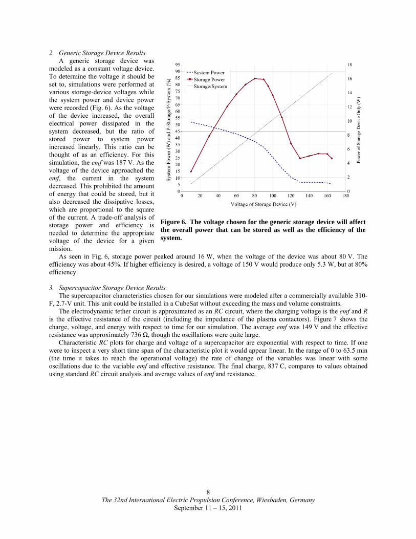
2. Generic Storage Device Results A generic storage device was
modeled as a constant voltage device. To determine the voltage it should be set to, simulations were performed at various storage-device voltages while the system power and device power were recorded (Fig. 6). As the voltage of the device increased, the overall electrical power dissipated in the system decreased, but the ratio of stored power to system power increased linearly. This ratio can be thought of as an efficiency. For this simulation, the emf was 187 V. As the voltage of the device approached the emf, the current in the system decreased. This prohibited the amount of energy that could be stored, but it also decreased the dissipative losses, which are proportional to the square of the current. A trade-off analysis of storage power and efficiency is needed to determine the appropriate voltage of the device for a given mission.
As seen in Fig. 6, storage power peaked around 16 W, when the voltage of the device was about 80 V. The efficiency was about 45%. If higher efficiency is desired, a voltage of 150 V would produce only 5.3 W, but at 80% efficiency. 3. Supercapacitor Storage Device Results
The supercapacitor characteristics chosen for our simulations were modeled after a commercially available 310-F, 2.7-V unit. This unit could be installed in a CubeSat without exceeding the mass and volume constraints.
The electrodynamic tether circuit is approximated as an RC circuit, where the charging voltage is the emf and R is the effective resistance of the circuit (including the impedance of the plasma contactors). Figure 7 shows the charge, voltage, and energy with respect to time for our simulation. The average emf was 149 V and the effective resistance was approximately 736 Ω, though the oscillations were quite large.
Characteristic RC plots for charge and voltage of a supercapacitor are exponential with respect to time. If one were to inspect a very short time span of the characteristic plot it would appear linear. In the range of 0 to 63.5 min (the time it takes to reach the operational voltage) the rate of change of the variables was linear with some oscillations due to the variable emf and effective resistance. The final charge, 837 C, compares to values obtained using standard RC circuit analysis and average values of emf and resistance.
Figure 6. The voltage chosen for the generic storage device will affect the overall power that can be stored as well as the efficiency of the system.

The 32nd International Electric Propulsion Conference, Wiesbaden, Germany
September 11 – 15, 2011
9
D. ChipSats and Nanospacecraft The growing success of nanospacecraft over the past decade has generated interest in exploring the potential for
even smaller spacecraft, both as stand-alone satellites or as a distributed swarm.13 Because of advances in integrated circuit and microelectromechanical systems (MEMS) technology, the feasibility of miniaturized spacecraft at the levels of fully monolithic semiconductor integrated circuits (10–100 mg) or hybrid integrated circuits (10–100 µg) is being seriously investigated.14,15 Effectively, this architecture can be thought of as a small “satellite-on-a-chip,” or “ChipSat”.
Flat ChipSat wafers suffer from an inherently high area-to-mass ratio. Although this feature can be exploited for new behaviors, it can result in an undesirably short orbital lifetime in LEO due to atmospheric drag, ranging from a few days to a few hours. While a satellite using chemical propulsion can overcome the continuous force of atmospheric drag, the volume of propellant required will increase with the satellite’s intended lifetime. Thus, the use of a traditional thruster with propellant and directed flow to compensate for drag and possibly for maneuverability would increase the size, mass, and complexity of ChipSats. To counter the drag force, a short, semi-rigid EDT for propulsion is considered, which keeps the overall ChipSat mass low and provides enough thrust to overcome drag in LEO.
A study was conducted that analyzed the ability to draw current from the ionosphere and thus generate thrust and compared this to the tether mass and material, electron emitter and collector types, and needed power to determine EDT capability of overcoming atmospheric drag forces.* The study led to the development of a system concept and mission scenario using the TeMPEST simulation tool to estimate tether voltages and currents based on tether configuration and ambient models. The results reveal that an insulated tether only a few meters long and tens of microns in diameter can provide milligram to gram-level ChipSats with complete drag cancellation and even the ability to change orbit (Fig. 8).11,16
* For more detail, please refer to “The Potential of Miniature Electrodynamic Tethers to Enhance Capabilities of Femtosatellites” by Bell et al. (IEPC-2011-054).
Figure 7. Supercapacitor-charging simulation using standard TeMPEST execution. The capacitor was modeled after a commercially available 310-F, 2.7-V unit.
Figure 8. TeMPEST simulation results of ChipSat orbit with and without the electrodynamic tether.

The 32nd International Electric Propulsion Conference, Wiesbaden, Germany
September 11 – 15, 2011
10
We expanded the trade study to include a range of ChipSats. The satellites in the trade study roughly span the
mass and ballistic coefficient range represented by actual pico and femtosatellites, as shown in Fig. 9. The mass and size of the largest satellite for the trade study (100 g, 5 cm × 5 cm × 2 cm) was motivated by the DARPA–Aerospace Corporation satellite PicoSat 1 and 2. PicoSat was launched in January 2000 for a 3-day mission and consisted of two 250-g satellites connected by a 30-m-long tether.17
The smallest and lightest satellite considered in the study (10 mg, 1 mm × 1 cm × 1 cm), was motivated by the Sprite ChipSat.18 The Sprite ChipSat is currently undergoing testing on the Materials International Space Station Pallet on the International Space Station. The remaining femtosatellite (1 g, 1 cm × 1 cm × 1 cm) bridges the mass and ballistic coefficient gap between the higher and lower mass satellites.
In the continuation of this trade study, the satellites were oriented so their minimum cross sectional area was perpendicular to velocity. Also, instead of collecting electrons with a biased conducting sphere, the electron collection is done by a second femtosatellite of the same size.
We have analyzed the EDT anode’s ability to draw current from the ionosphere and through the tether, thereby generating thrust, and have traded this performance against the tether mass and material, tether rigidity, and power needed to determine the EDT’s capability of overcoming atmospheric drag forces. The 3 EDT systems outlined in Table 1 are able to overcome the force of atmospheric drag.
V. Conclusion An electrodynamic tether can be used by satellites to harvest energy from the “orbital battery” by using the
Lorentz force interaction with the geomagnetic field. The amount of energy that can be harvested depends on the length of the tether, the type of tether, and the configuration of the plasma contactors. Satellite size sets the bounds for the configuration of the EDT system and, therefore, the magnitude of the energy budget. Large satellites have the potential to harvest as much as kilowatts at the load. Small EDT systems the size of CubeSats have the potential to produce more energy than mounted solar panels alone. EDT systems benefit very small, ChipSat-sized satellites by enabling them to maintain orbit without a significant contribution to the satellites’ size and mass or the need for expendable propellant. We developed system concepts for ChipSat-sized satellites by investigating materials and their characteristics. In addition, our system modeling capabilities were improved by comparing existing plasma contactor models and by adding modules that compare changes in orbital energy to the electrical energy dissipated or stored.
Table 1. System concepts outlined for EDT-systems capable of overcoming atmospheric drag.
Parameter 10-mg Satellite 1-g Satellite 100-g Satellite
Dimensions 1 mm × 1 cm × 1 cm 1 cm ×1 cm × 1 cm 2 cm × 5 cm × 5 cm
Ram cross-sectional area 0.1 cm2 1 cm2 10 cm2
EDT length 1 m 3 m 10 m
Tether diameter 24µm 66 µm 212 µm
Tether mass 3 mg 80 mg 3 g
Available power (estimated) 13 mW 40 mW 600 mW
Current 214 µA 403 µA 1250 µA
Anode Potential 17 V 52 V 430 V
0.01
0.1
1
10
100
1.0E‐03 1.0E‐01 1.0E+01 1.0E+03Maximum Ballistic Coefficient, kg/cm2
Satellite Mass ,g
Satellite concepts‐ for trade study
Surrey PCBSat
DARPA/Aerospace Corp. Picosat 1/2
Surrey SpaceChip
Cornell PCB COTS Sat
Cornell MCM Sat
Cornell Sprite ChipSat
Figure 9. Ballistic coefficient for a range of ultra-small satellites assuming the smallest area cross-section.17-19

The 32nd International Electric Propulsion Conference, Wiesbaden, Germany
September 11 – 15, 2011
11
Acknowledgments We gratefully acknowledge support from AFOSR grant FA9550-09-1-0646.
References 1Gilchrist, B.E., Thompson, D.C., Raitt, W.J., Voronka, N., Agüero, V., Williams, S.D., Bilén, S.G., and Bonifazi, C.,
“Measurements of Current and Voltage in the TSS–1R System Using Passive Current Closure and Electron Beam Emission from the Orbiter Structure,” 1996 Spring AGU Meeting, Baltimore, MD, May 1996.
2“Space Tethers: Technology Status and Technology Maturation Needs,” AIAA Space Tethers Technical Committee, Draft, Spring 2011.
3Forward, R.L., and Hoyt, R.P., “Failsafe Multiline Hoytether Lifetimes,” AIAA-95-2890, 31st AIAA/SAE/ASME/ASEE Joint Propulsion Conference, San Diego, CA, July 1995.
4Banks, P.M., “Review of Electrodynamic Tethers for Space Plasma Science,” J. Spacecraft and Rockets, Vol. 26, No. 4, pp. 234–239, 1989.
5Sanmartín, J.R., Martinez–Sánchez, M., and Ahedo, E., “Bare Wire Anodes for Electrodynamic Tethers,” J. Prop. and Power, Vol. 9, No. 3, pp. 353–360, 1993.
6Fuhrhop, K R., and Gilchrist, B E., “Electrodynamic Tether System Analysis Comparing Various Mission Scenarios,” 41st AIAA/ASME/SAE/ASEE Joint Propulsion Conference & Exhibit, 10–13 July, 2005.
7Hoyt, R.P., Slostad, J.T., and Voronka, N.R., “The Microsatellite Propellantless Electrodynamic Tether (PET) Propulsion System,” 52nd Joint Army Navy NASA Air Force (JANNAF) Propulsion Meeting, Las Vegas, NV, 12–13 May 2004.
8Hoyt, R.P., Slostad, J.T., Frank, S.S., and Voronka, N.R., “Momentum-Exchange/Electrodynamic Reboost (MXER) Tethers for Low-Cost Orbit Transfer,” 52nd Joint Army, Navy, NASA, Air Force (JANNAF) Propulsion Meeting, Las Vegas, NV, 12–13 May 2004.
9I. Katz et al., “Plasma Turbulence Enhanced Current Collection: Results from the Plasma Motor Generator Electrodynamic Tether Flight,” J. Geophys. Res., Vol. 100, No. A2, pp. 1687–1690, Feb. 1995.
10Gerver, M.J., Hastings, D.E., Oberhardt, M.R., “Theory of Plasma Contactors in Ground-Based Experiments and Low Earth Orbit,” J. Spacecraft and Rockets, Vol. 27, No. 4, p. 391, July 1990.
11Bilén, S., McTernan, J., Gilchrist, B., Bell, I., Voronka, N., and Hoyt, R., “Electrodynamic Tethers for Energy Harvesting and Propulsion on Space Platforms,” AIAA Space 2010 Conference & Exposition, 30 August–2 September, 2010.
12CubeSat Design Specification Rev. 12, The CubeSat Program, Cal. Poly, SLO. 13Barnhart, D., Vladimirova, T., and Sweeting, M., “Very-small-satellite Design for Distributed Space Missions,” J. of
Spacecraft and Rockets, Vol. 44, No. 6, pp. 1294–1306, 2007. 14Atchison, J., and Peck, M., “Length Scaling in Spacecraft Dynamics,” Journal of Guidance, Control, and Dynamics, Vol.
34, No. 1, pp. 231–246, 2011. 15Atchison, J.A. and Peck, M., “A Millimeter-Scale Lorentz-Propelled Spacecraft,” AIAA 2007-6847, AIAA Guidance,
Navigation and Control Conference and Exhibit, 20–23 August 2007. 16Bell, I.C., et al., “Electrodynamic Tethers for ChipSat and Nanospacecrafts,” Poster, Spacecraft Charging and Technology
Conference, Albuquerque, NM, 23 Sept. 2010. 17Tang, W.C., “Overview of MEMS Programs at DARPA and Applications in Space,” Presentation, First Canadian
Workshop on MEMS technology for Aerospace Applications, National Research Council, Canada, April 12, 2001. 18Peck, M., “A Vision for Milligram-scale Spacecraft,” Presentation, Brown University ChipSat Workshop. Providence, RI,
Feb 18, 2010. 19Barnhart, D.J., “Very Small Satellite Design for Space Sensor Networks,” Presentation, Brown University ChipSat
Workshop, Feb 18, 2010.